ecom-0049-f c~high energy c avac hors for … · xxc audible momentary breakdown at elevated...
TRANSCRIPT

'.,'Research and Development Technical Report
- ECOM-0049-F
C~HIGH ENERGY C AVAC hORSFOR
=MODERATE REPETITION RATEFIA0RPR
B0
0ICordHlegadHretRc
MA017
DITIBTO STTEEN
Aprvdfr0bi ees;dsrbto ni ie
Doal filsrtosi
FIALREOTIOA TECHICASP AU*LCTI O P N IFR ATIO SERVICE
S,-vf A 25
NORT ADAMS, MASAHSET

logTIS o;/].'I S •,
.......... ...... ... . . ..".. ..
ly.. I. ................N O TIC E SDISTNIRUIJ~ONM AIU¶It, CE3
Disclaimers
The findings in this report are not to be construed as anofficial Department of the Army position, unless so desig-nated by other authorized documents.
The cita+ion of trade names and names of manufacturers inthis report is not to be construed as official Governmentindorsement or approval of commercial products or servicesreferenced herein.
Disposition
Destroy this report when it is no longer needed. Do notreturn it to the originator.
*~II
L .. . .. . . . .. . . . . .. . . . -

UnclassifiedSeurty Classification
DOCUMENT CON4TROL DATA - R &D',(Security defesitelctlon of it*1., body at abetrect and Indeuing ainnotatlion must be fn Ifed Whon the ov"al re tIs classildod)
I. ORIGINATING ACTIVITY (C0#porste author) "c.REPORT SECURITY CLASSIFICATION
Sprague I'lectric Company UnclassifiedNorth Adams, Massachusetts 012472.GOP
3. REPORT TITLE
H-igh Energy Capacitors for Moderate Repetition Rate
4 0G5C`IW-T:',E . OTES (Type of report and Inclusive date*)Final Report (Period: 30 October 1970 to 29 January 1972)
S. UTKCA(SI (First n,.,4e, middle initial, ats name)
Conrad Ha'.berg and Herbert Rice
f AtEPORT DATE 74. TOTAL NO. OF PAGES 17b. NO. OF REFS
;% May ~972 118I$4. CONTRACT OR GRANT NO. Sm. ORIGINATOR'S REPORT NUMBER(S)
TDAABO7-71 -C-0049b. PROJECT NO. A119-51
IS6 62705A 057C. 9b, OTHER REPORT NO(S) (Any other numbers that may be assigned
Task 05 this report)
d. ECOM-0049-Fd.Subtask 36
10. DISTRIBUTION STATEMENT
Approved for public release; distribution unlimited.
11. SUPPLEMENTARY NOTES 1(2. SPONSORING MILITARY ACTIVITY
U. S. Army Electronics CommandIFort Monmouth, New Jersey 07703_______________________ A TTN:_AMSEL-TL-SL
'3. ABSTRACT
'Capacitors of six designs were designed, constructed andmeasured for various electrical characteristics. Two designswere chosen for further work in Phase 11 on the basis of thesemeasurements and 100, 000 charge -discharge life test data.
In Phase II, two designs were constructed in three variationsand further discharge life tested for a total of 10, 000, 000charge -discharge cycles or until failure. The best designwas chosen for work in Phase III.
In Phase III, capacitors were constructed and discharge life testedfor 50, 000, 000 charge -discharge cycles or until failure. Onecapaicitor failed at 10, 000, 000 charge -discharge cycles while theremaining five capacitors completed 50, 000, 000 charge-dischargecycles. All six capacitors met the contract requirements ofdelivering 12 joules of energy at 900 V and weighing less than sixounces.
k.ŽDD 1NOV.51473 UnclassifiedSecurity Classification

Unclassified .1Security Classification
14. LINK A LINK 0 LINK CKIEL WORD$
WoL WT ROLE WT 'OoL. W T
CapacitorsEnergy Dis:harge CapacitorsLaser CapacitorsDielectric
t-
IUnclassifiedsecurity Classiticition
TR ECOM-0049-F Reports Control SymbolMAY 1972 OSD-1366
HIGH ENERGY CAPACITORSFOR
MODERATE REPETITION RATE
Final Report
30 October 1970 to 29 January 1972
CONTRACT NO. DAAB07-71-C-0049DA PROJECT NO. 1S6 62705A 057 05 36
DISTRIBUTION STATEMENTApproved for public release; distribution unlimited.
Prepared by
Conrad Halberg and Herbert Rice
SPRAGUE ELECTRIC COMPANYNorth Adams, Massachusetts 01247
FOR
U. S. ARMY ELECTRONICS COMMAND, FORT MONMOUTH, N. J.
!" ic.
ABSTRACT
Capacitors of six designs were designed, constructed and measuredfor va.rious electrical characteristics. Two designs were chosenfor further work in Phase II on the basis of these measurements and100, 000 charge-discharge life test data.
In Phase II, two designs were constructed in three variations andfurther discharge life tested for a total of 10,000,000 charge-discharge cycles or until failure. The best design was chosen forwork in Phase III.
In Phase III, capacitors were constructed and discharge life testedfor 50, 000, 000 charge-discharge cycles or until failure. Onecapacitor failed at 10, 000, 000 charge-discharge cycles while theremaining five capacitors completed 50, 000, 000 charge-dischargecycles. All six capacitors met the contract requirements of deliver-ing 12 joules of energy at 900V and weighing less than six ounces.
Pid
S~Preceding page blankV iii

',,
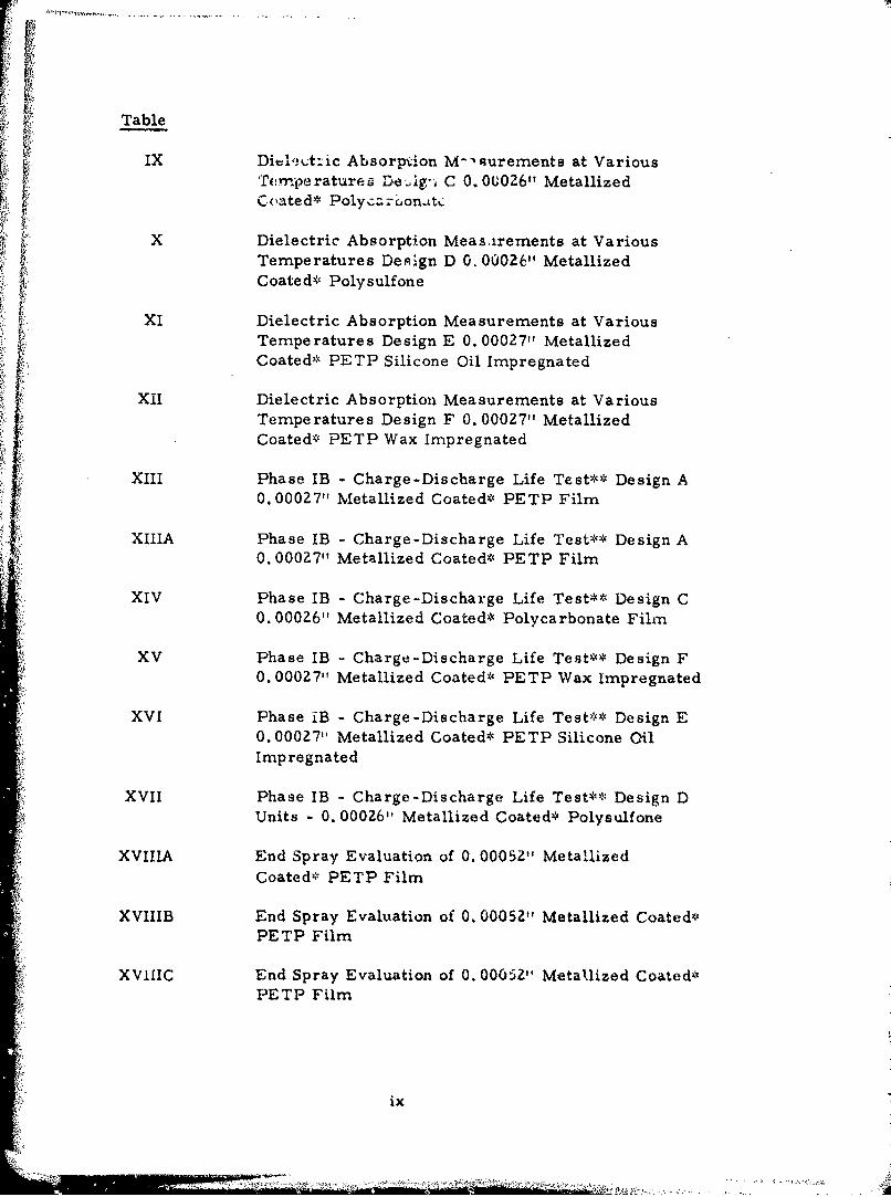
TABLE OF CONTENTS
Page
ABSTRACT iii
LIST OF ILLUSTRATIONS vi
LIST OF TABLES vii
SECTION I - INTRODUCTION
1. General 12. Discussion 1
SECTION II NARRATIVE AND DISCUSSION1. Objective 32. Phase I Designs 43. Capacitance Change 64. Breakdown Test 65. Dielectric Absorption 356. Test Equipment 357. Testing and Evaluation 428. Design Selection 539. End Connection 53
"10. Phase I Extension 5511. Phase II 5512. Testing and Evaluation 6213. Phase III 77
SECTION III - CONCLUSIONS AND RECOMMENDATIONS 91
it
Preceding page blank
V
LIST OF ILLUSTRATIONS
Figure
1 Comparison of Coated vs Uncoated PETP Film
2 Capacitance vs Temperature
3 Capacitance versus Temperature
4 Capacitance vs Temperature for MetallizedCoated* Polysulfone Units
Capacitance vs Temperature for Silicone OilImpregnated Metailized Coated* PETP
6 Capacitance vs Temperature for Bareco WaxImpregnated Metallized Coated* PETP
7 Percentage Capacitance Change vs Temperature
8 CADET III
9 Wiring Diagram for CADET III
10 CADET III with Oven Door Open
11 CADET III Test Equipment 1-30 pps Test Station
12 Typical Wave Shapes of Discharge Current
13 Comparisoo of Film with and without Loss of EndConnection
1,4 (Left to Right) State-of-the-Art, Final Design andInitial Design Capacitors
15 Capacitance Change vs Temperature
vi
. . . . .

LIST OF TABLES
Table
I Polymer Film Dielectric Systems Review
IIA Phase IB - Electrical Evaluation (-40*C) Design AUnits - 0. 00027", Metallized Coated* PETP Film
IIB Phase LB - Electrical Evaluation (+2,50 C) Design AUnits - 0. 00027", Metallized Coated* PE TP Film
HG Phase LB - Elertrical Evaluation (+40OC) Design AUnits - 0. 00027"1 Metallized Coated* PETP Film
LID Phase LB - Electrical Evaluation (+85*C) Design AUnits - 0. 000271, Metallized Coated* PETP Film
IIIA Phase LB - Electrical Evaluation (-40*C) Design CUnits - 0. 00026", Metallized Coated* PolycarbonateFilm
ILIB Phase LB - Electrical Evaluation (+Z5*C) Design CUnits - 0. 00026", Metallized Coated* PolycarbonateFilm
ILIC Phase LB - Electrical Evaluation (±40*C) Design CUnits - 0. 00026', Metallized Coated* PolycarbonateFilm
HID Phase LB - Electrical Evaluation (+85GC) Design CUnits - 0. 00026", Metallized Coated* PolycarbonateFilm
IVA Phase LB - Electrical Evaluation (-40GC) Design DUnits -0. 00026", Metallized Coated* Polysulfone
vii
1'A
Table
IVB Phase IB - Electrical Evaluation (+Z5 0 C) Design DUnits - 0. 00026" Metallized Coated* Polysulfone
IVC Phase IB - Electrical Evaluation (+40*C) Design D• Units - 0. 00026" Metallized Coated* Polysulfone
IVD Phase IB - Electrical Evaluation (+85*C) Design DUnits - 0. 00026" Metallized Coated* Polysulfone
VA Phase 1B - Electrical Evaluation (-40°C) Design E0.000i 71 Metallized Coated* PETP Silicone OilImpregnated
VB Phase IB - Electrical Evaluation (+25C) Design E0. 000Z7" Metallized Coated* PETP Silicone OilImpregnated
VC Phase IB - Electrical Evaluation (+40*C) Design E0. 00027" Metallized Coated* PETP Silicone OilImpregnated
VD Phase IB - Electrical Evaluation (+85°C) Design E0. 00027" Metallized Coated* PETP Silicone OilImpregnated
VIA Phase IB - Electrical Evaluation (-40°C) Design F0. 00027" Metallized Coated* PETP Wax Impregnated
VIB Phase IB - Electrical Evaluation (+25*C) Design F0. 00027" Metallized Coated* PETP Wax Impregnated
VIC Phase IB - Electrical Evaluation (+400C) Design F0. 000Z7" Metallized Coated* PETP Wax Impregnated
VID Phase IB - Electrical Evaluation (+85°C) Design F
0. 000Z7" Metallized Coated* PETP Wax Impregnated
VII Breakdown Voltage (Room Temperature)
VIII Dielectric Absorption Measurements at VariousTemperatures Design A 0. 00027" Metallized Coated*PETP
viii
Table
IX Di%-,,,t;tic Absorption M-surements at VariousTemperatures Dg C 0. 000261, MetallizedCoa~ted* Polyc Z'r~jon-ttc
X Dielectric Absorption Measarements at VariousS. Temperatures Design D 0. 00026"1 Metallized
Coated* Polysulfone
tXI Dielectric Absorption Measurements at Various
Temperatures Design E 0. 00027", Metallized
Coated* PETP Silicone Oil Impregnated
XII Dielectric Absorption Measurements at VariousTemperatures Design F 0. 00027", MetallizedI Coated*- PETP Wax Impregnated
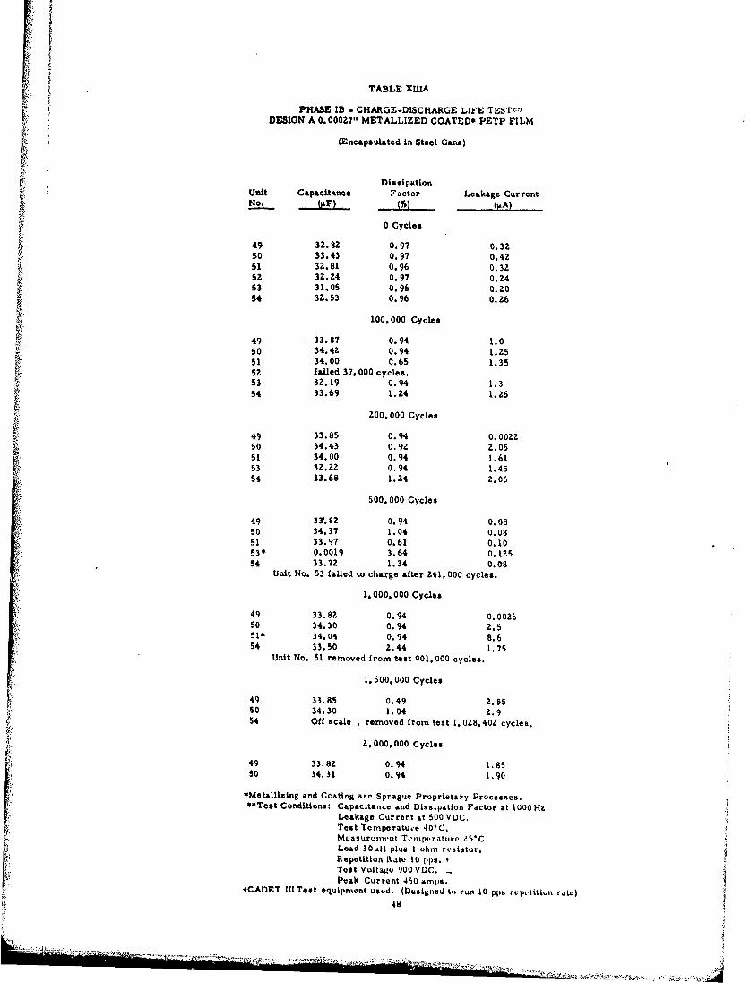
XIII Phase IB - Charge -Discharge Life Test** Design A0. 00027", Metallized Coated* PETP FilmI.XIIIA Phase IB - Charge -Discharge Life Test** Design A0. 0002 7" Metallized Coated* PETP Film
XIV Phase lB - Charge -Discharge Life Test** Design C0. 00026"1 Metallized Coated* Polycarbonate Film
XV Phase IB - Charge -Discharge Life Test** Design F0. 00027", Metallized Coated* PETP Wax Impregnated
XVI Phase iB - Charge -Discharge Life Test** Design E0. 00027", Metallized Coated* PETP Silicone OilImpregnated
XVII Phase IB -Charge -Discharge Life Test** Design DUnits -0. 00026"1 Metallized Coated* Polysulf one
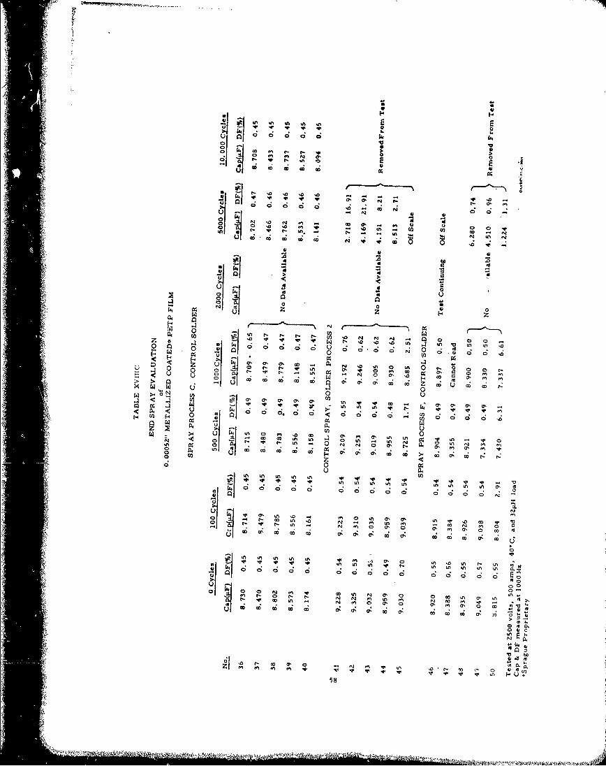
XVIIIA End Spray Evaluation of 0. 00052" MetallizedCoated* PETP Film
XVIIIB End Spray Evaluation of 0. 00052", Metallized Coatedy,PETP Film
XV1IIC End Spray Evaluation of 0. 00052Z" Metallized Coated*PETP Film
ix

Table
t XIX Continuation of Phase 1B Charge-Discharge LifeTesting Design E - 0. 00027" Metallized Coated*PETP Silicnae Oil Impregnated
XXA Audible Momentary Breakdown at Elevated Temperatureat I kV Design A Variation 1 (0. 00027"1 MetallizedCoated* PETP, Different Geometry) Spray Process C,Solder Process I
XXB Audible Momentary Breakdown at Elevated Temperatureat 1 kV Design A Variation 2 (0. 00027' MetallizedCoated* PETP, Standard Design) Spray Process C,Solder Proceis I
XXC Audible Momentary Breakdown at Elevated Temperatureat I kV Design A Variation 3 (0. 00027" MetallizedCoated* PETP, Standard Design) Spray Process A,Solder Process I
XXD Audible Momentary Breakdown at Elevated Temperatureat I kV Design E Variation 1 (0. 00027" MetallizedCoated* PETP, Different Geometry, Silicone OilImpregnated) Spray Process C, Solder Process I
XXE Audible Momentary Breakdown at Elevated Temperatureat I kV Design E Variation 2 (0. 00027" MetallizedCoated* PETP, Standard Design, Silicone OilImpregnated) Spray Process C, Solder Process I
XXF Audible Momentary Breakdown at Elevated Temperatureat I kV Design A Variation 3 (0. 00027" MetallizedCoated* PETP, Standard Design, Silicone OilImpregnated) Spray Process A, Solder Process I
Xxi Effective Series inductance
XXII Charge-Dincharge Life Testing Design A Variation I(0.00027" Metallized Coated,, PETP, DifferentGeometry) Spray Process C, Solder Process I
XXIllI Charge-Discharge Life Testing Design A Variation 20. 00027" Metallized Coated& PETP Standard Design)
Spray Process C, Solder Process i)
x
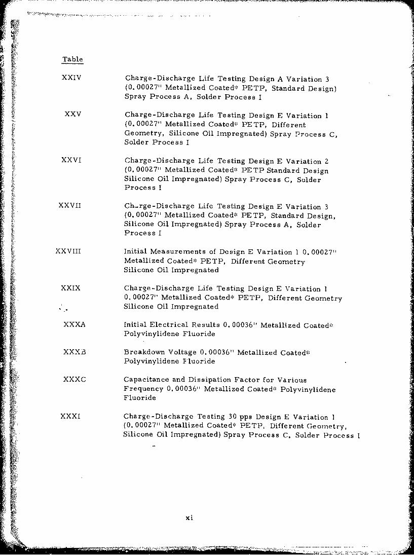
V
Table
XXIV Charge-Discharge Life Testing Design A Variation 3(0. 00027" Metallized Coated-' PETP, Standard Design)Spray Process A, Solder Process I
XXV Charge-Discharge Life Testing Design E Variation 1(0. 00027" Metallized Coated-'." PETP, DifferentGeometry, Silicone Oil Impregnated) Spray Process C,Solder Process I
XXVI Charge-Discharge Life Testing Design E Variation 2(0. 00027" Metallized Coated*c PETP Standard DesignSilicone Oil Impregnated) Spray Process C, SolderProcess I
XXVII Ch..rge-Discharge Life Testing Design E Variation 3(0. 00027" Metallized Coated* PETP, Standard Design,Silicone Oil Impregnated) Spray Process A, SolderProcess I
XXVIII Initial Measurements of Design E Variation 1 0. 00027"Metallized Coated' PETP, Different GeometrySilicone Oil Impregnated
XXiX Charge-Discharge Life Testing Design E Variation 1
0. 00027" Metallized Coated-,` PETP, Different GeometrySilicone Oil Impregnated
XXXA Initial Electrical Results 0. 00036" Metallized Coated,',Polyvinylidene Fluoride
XXXB Breakdown Voltage 0. 00036" Metallized Coated*Polyvinylidene Fluoride
XXXC Capacitance and Dissipation Factor for VariousFrequency 0. 00036" Metallized Coated* PolyvinylideneFluoride
XXXI Charge-Discharge Testing 30 pps Design E Variation I(0. 00027" Metallized Coated", PETP, Different Geometry,Silicone Oil Impregnated) Spray Process C, Solder Process I
xi
Ur AM, A
SECTION I
INTRODUCTION
1. General
The object of this research effort was the development ofhigh-energy capacitors of minimum weight for moderate repetitionrate, non-oscillatory discharge applications, such as target andarea illuminators. Specifically, the capacitors, when charged to900 volts and discharged through a 1 ohm resistor in series witha 30 microhenry inductor, had to deliver not less than 12 joulesfor the entire temperature range of -40*C to +85°C. The corre-sponding capaci:.ance for this requirement was 30 ýiF, minimum.The repetition . .or discharge of the capacitors was to be 10pulses per second (pps), and the minimum life objective was5.0 x 107 discharges at ambient temperature of 40°C. The capacitorweight objective was six (6) ounces maximum. Emphasis in theeffort was placed on the maximizing of the energy-to-weight ratio.
2. Discussion
There are a number of ways in which the energy-to-weightratio of capacitors may be increased. The most obvious methodis to employ a dielectric and/or impregnant system having a highdielectric constant. More efficient is the use of a dielectric systemcapable of withstanding high voltage stresses. The energy densityincreases as the square of the voltage rating, and is also propor-tional to the dielectric constant.
Still another method involves the use cf metallized electrodes.This improves the weight efficiency (energy-to-weight ratio) in twoways. First, metallized electrodes are much thinner than the foilelectrodes commonly used. This means a lighter capacitor than
ýKf obtainable with an energy-comparable foil electrode. Secondly, a[ metallized capacitor is capable of operating at higher voltage
stresses for a given dielectric thickness. This is due to the "self-healing" character of metallized capacitors. In the event of adielectric failure in a foil type capacitor, high currents flow atthe point of rupture, and the adjacent dielectrics and foils aredamaged. Thus, the capacitor shorts, and is rendered inoperable.On the other hand, as the case of a dielectric failure in a metallizedcapacitor, an electric a--c is drawn between the two electrodes,This arc vaporizes the metal film from around the area of thebreakdown. The vaporized metal and gases released from thedielectric increases the pressure in the area of the breakdown.Both the arc length and the pressure increase until the arc canno longer be sustained. The capacitor, thus, remains operablewith little or no change in its electrical properties.
2 ii
- . ~~ - ---..
1',

SECTION II
NARRATIVE AND DISCUSSION
1. Objective
The objective of this development effort was the developmentof a light weight high energy capacitor supplying 1 Z joules of energyat 900 volts. The energy of a capacitor is described by the equation:
E = I/ZCV2
E = EnergyC = Capacity in FaradsV = Voltage in Volts
, 'The capacity is determined by the equation:
S~AKei ~C-
C Capacity
A Ared of the plates in square metersConstant 8.8- :. 10- 1 2 coulombs?
•° Nevtc:cn meterZ
e= Dielectric constantT = Distance between the plates in meters
Since mass is determined by the equation:
M=ATDM = MassA = Area in meters (3)T Thickness in meters
116 D = Density in Kg/mn3
Substituting Equation 3 into Equation Z, the result is
C MK (4)S- ~~D T-(4
3
L.

22Substituting Equation 4 into Equation 1, the re suit is
i/2MKc V 2E TLD (5)
Since in this development effort:
E = 12 joulesV = 900V
the result is:
3. 36x106 T 2 D
An equation which relates mass, thickness of the dielectric, densityof the dielectric and the dielectric constant results.
From this equation it becomes evident that the mass of a cap-acitor section excluding margins, extensions and end spray is abalance between the thickness of available material, the density ofthe material and the dielectric constant. The thickness is thedominant factor. The mass and thickness of the electrodes can beneglected because we are dealing with metallized capacitors. Usingthis equation a review was made of available dielectric films whichwould be capable of operating at 900V. The results of this surveyare shown in Table I. As can be seen, the most promising dielectricswere Polyethylene Terephthalate (PETP), Polycarbonate and Polysulfone.
2. Phase I Designs
The designs chosen for Phase I were:
Design A - 0. 000277" metallized coated* Polyethylene Terephthalate (PETP)Design B - 0. 00022" metallized coated* Polyethylene TerephthalateDesign C - 0. 00026" metallized coated* PolycarbonateDesign D - 0. 00027" metallized coated* PolysulfoneDesign E - 0. 00027" metallized coated* PETP, silicone oil impregnatedDesign F - 0. 00027" metallized coated* PETP, Bareco wax impregnated
All the dielectric films were coated to aid in the clearing (selfhealing) of the capacitors. During the clearing the coating helps form
*Metallizing and Coating are Sprague Proprietary Processes
4 'A

0 -4
94 UU
* * 5IaD
4 u 0LAA I k : co
a 00
144
) 0~ C- a
0~s 0
04
0 >
In2.o co-INI
* : -)I

gases and reduces the chances for formation of low resistance deposits.A comparison of clearing for coated and uncoated PETP is shown inFigure 1. All designs utilized film which was 4", wide with 3/16"margins.
After n'etallizing, coating and slitting, sections were rolled,vacuum dried, end-sprayed and had leads attached in the normalmanner. The sections were then cleared at 1000VDC. Sections ofDesign B failed to withstand the voltage and shorted between 700 o
800V. Further work on this design war discontinued.
The sections were then encapsulatecd in steel cans even thoughthe final units were encapsulated in aluminum cans. There was noadvantage to warrant the additional cost of aluminum cans in Phase I.Designs E and F were impregnated using standard impregnationte chnique s.
3. Capacitance Change
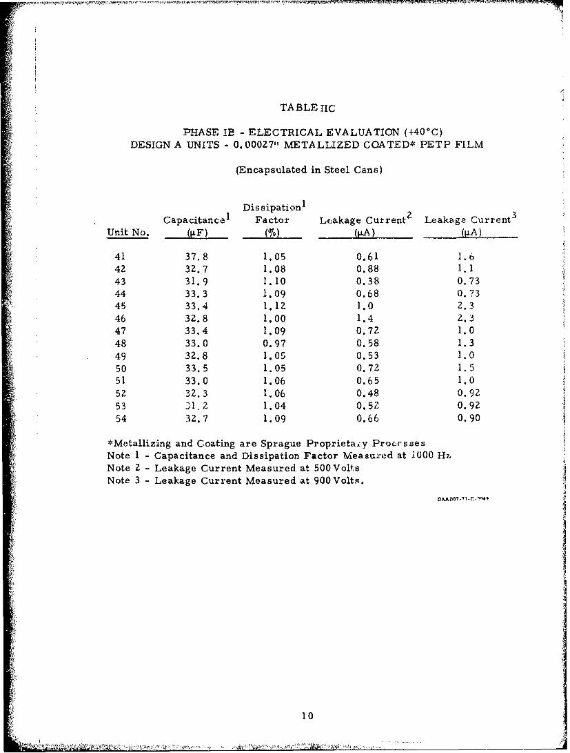
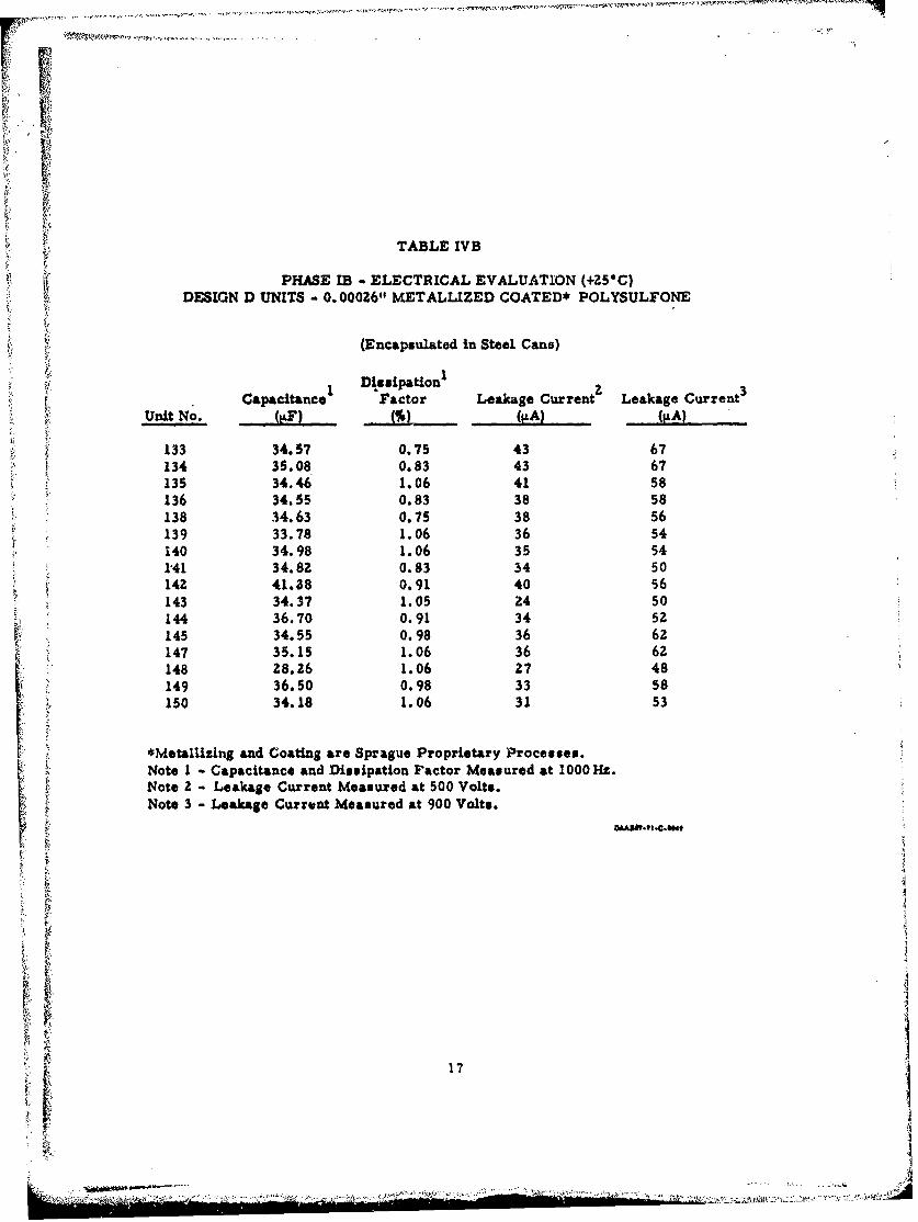
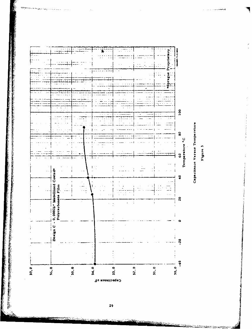
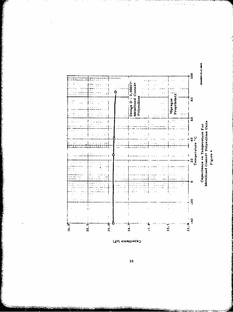
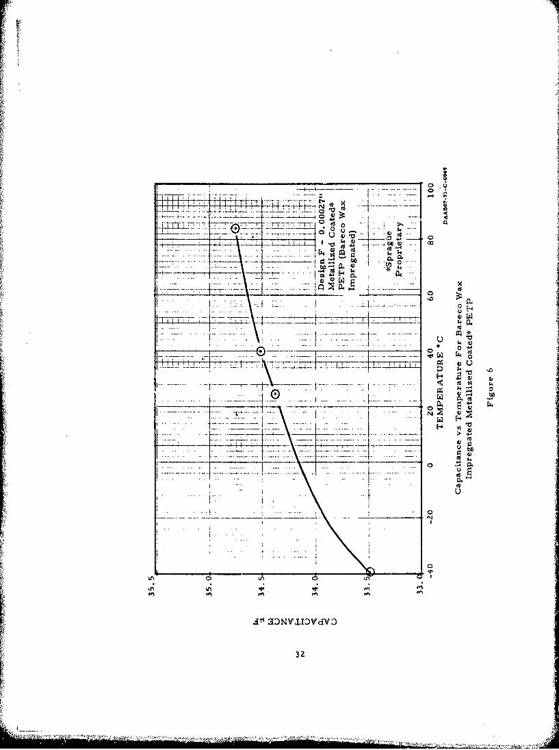
The finished units were read for capacitance, dissipation factorand leakage current at -40°C, +25*C, +40°C and +85°C. The resultsof these measurements are shown in Tables II - VI. The highleakage current of Design D was due to the base polysulfone filmbeing attacked by the solvents during the coating process. The highdissipation factor reading of Design C was due to the long leadsnecessary for measuring inside the temperature cycling chamber.The change in capacitance with temperature for Designs A, C, D,E and F are shown in Figures 2 through 6. As shown in Figure 7,Designs A, E and F exhibit approximately the same shape curve forpercentage capacitance change versus temperature. Design Dexhibits an almost perfectly flat profile from -55°C to +85 0 C,changing only -. 11% over the entire temperature range.
4. Breakdown Test
A sample of each design was tested for breakdown voltage. Theresults of this testing are shown in Table VII. Because breakdownvoltage of Design B was below the contract specified operating voltage,further work on this design was discontinued. The slightly higherbreakdown voltages of Deýsigns E and F compared to Design A in-dicated that little dielectric strength was gained by impregnation ofthis type of unit.
6

CO~~
-y1 44
FAULTS POORLY CLEAPED -METALLI-ZED PETP FILM(NOTE: Carbon deposit in center of clearing)
ýCOM PL ETELY C LEARED FAULTS -METALLIZED CO'ATED-- PET -P FIL M
(No cnrbon deposits)
COMPARISON OF COATED vs UNCOATED PETP FILM
Figure 1

TABLE IIA
PHASE IB - ELECTRICAL EVALUATION (-40°C)DESIGN A UNITS - 0. 000Z7" METALLIZED COATED* PETP FILM
(Encapsulated in Steel Cans)
Dissipation2Capacitancel Factor Leakage Currentz Leakage Current 3
Unit No. L(iF) M (IiA) (IiA)
41 35.7 1.75 0.22 0.3942 31.1 1.56 0.18 0.3243 30.6 1.62 0.20 0.3644 31.6 1.54 0.20 0.3845 31.7 1.46 0.35 0.63
46 31.4 1.72 0.35 0.6747 32.1 1.48 0.27 0.48
48 31.7 1.48 0.29 0.5249 31.5 1.62 0.20 0.54
50 31.8 1.40 0.16 0.4751 31.5 1.46 0.18 0.3552 30.8 1.54 0.14 0.27
53 29.7 1.68 0.20 0.3354 31.2 1.49 0.21 0.44
*Metallizing and Coating are Sprague Proprietary ProcessesNote 1 - Capacitance and Dissipation Factor Measured at 1000 HzNote 2 - Leakage Current Measured at 500 VoltsNote 3 - Leakage Current Measured at 900 Volts.
DAA5O7-. -C-0049
8
'•' ' •a

TABLE IIB
PHASE IB - ELECTRICAL EVALUATION (+25C)DESIGN A UNITS - 0.00027" METALLIZED COATED* PETP FILM
(Encapsulated in Steel Cans)E!
Dissipation1
1 2Capacitance Factor Leakage Current Leakage Current3
Unit No. (jiF) M (p.A) (IiA)
41 37.4 1.05 0.41 0.7542 32.6 1.05 0.22 0.3943 31.8 1.10 0.26 0.4344 33.3 0.95 0.25 0.4545 33.2 0.94 0.40 0.7046 32.9 0.96 0.38 0.7247 33.3 0.97 0.26 0.4748 33.2 0.97 - 0.32 0.5849 32.8 0.96 0.32 0.5b50 33.4 0.97 0.42 0.7251 32.8 0.96 0.32 0.5952 32.2 0.97 0.24 0.4153 31.0 0.96 0.20 0.3454 32.5 0.96 0.26 0.45
*Metallizing and Coating are Sprague Proprietary ProcessesNote 1 - Capacitance and Dissipation Factor Measured at 1000 HzNote 2 - Leakage Current Measured at 500 VoltsNote 3 - Leakage Current Measured at 900Volts.
DAA8#7.71 .C.0040
"9
AT
TABLE TIC
PHASE 1E - ELECTRICAL EVALUATION (+40 0 C)DESIGN A UNITS - 0.00027T, METALLIZED COATED* PETP FILM
(Encapsulated in Steel Cans)
Dis sipationI
Capacitance 1 Factor Le.akage Current 2 Leakage Current 3
Unit No. (MF) (%. (IiA) (1,A)
41 37.8 1.05 0.61 1.642 32.7 1.08 0.88 1.143 31.9 1.10 0.38 0.7344 33.3 1.09 0.68 0.7345 33.4 1.12 1.0 2.346 32.8 1.00 1.4 2.347 33.4 1.09 0.72 1.048 33.0 0.97 0.58 1.349 32.8 1. 05 0.53 1.050 33.5 1.05 0.72 1.551 33.0 1.06 0.65 1.052 32.3 1.06 0.48 0.9253 31.2 1.04 0.52 0.9254 32.7 1.09 0.66 0.90
*Metallizing and Coating are Sprague Proprietaiy Pro~csses
Note 1 - Capacitance and Dissipation Factor Measured at O000 H2,Note 2 - Leakage Current Measured at 500 VoltsNote 3 - Leakage Current Measured at 900 Volts.
10

TABLE IID
PHASE IB - ELECTRICAL EVALUATION (+85-C)DESIGN A UNITS - 0.00027" METALLIZED COATED* PETP FILM
(Encapsulated in Steel Cans)
1Cpctne DissipationC Factor Leakage Current Leakage Current
Unit No. (hF) (%) (IA) (IiA)W.
41 0.34 17 3542 33.2 0.30 13 2743 34.8 0.30 10 2044 34.9 0.26 12 2145 34.3 0.27 20 3546 34.7 0.26 17 3847 34.2 0.25 18 3348 34.0 0.27 21 4049 34.5 0.28 13 2750 34.2 0.29 18 3951 33.2 0.27 12 2552 32.2 0.28 12 2253 33.8 0.29 25 4554 34.5 0.29 23 43
*Metallizing and Coating are Sprague Proprietary ProcessesNote 1 - Capacitance and Dissipation Factor Measured at 1000 HzNote 2 - Leakage Current Measured at 500 Volts
It is noted that the leakage current is higher than anticipatedbut it is considered that the values listed are within acceptabledesign limits.
Note 3 - Leakage Current Measured at 900 Volts.
11

TABLE IIIA
PHASE IB - ELECTRICAL EVALUATION (-40-C)•ik DESIGN C UNITS - 0.00026" METALLIZED COATED* POLYCARBONATE FILM
(Encapsulated in Steel Cans)
1,31 DissipationCapacitancer Factor Leakage Current Leakage Current
Unit No. (4.F) (PA) - (gA)
109 Off Scale 0.19 0.36110 32.95 6.83 0.70 1.40ill 3Z.38 2.8Z 0.20 0.53112 37.78 2.95 0.12 0.30113 33.60 3.77 0.18 0.35114 33.00 12. 88 0. •4 0.40
115 33.68 4.05 0.26 0.50116 32.65 4.78 0.26 0.60117 33.68 3.25 0.76 0.90118 34.45 5.57 0.20 0.36119 33.57 4.12 0.5 0.90120 33.30 3.95 0.18 0.36121 36.74 3.35 0.22 0.40
< 122 32,.82 4.2?4 0.75 1. 0012.3 34.15 3.40 0.20 0.4612 I4 34.78 3.77 0.20 0.36
125 36.70 4.45 0.20 0.34126 34.70 3.40 0.10 0.30
*Metallizing and Coating are Sprague Proprieta;ýy Processes.Note 1 - Capacitance and Dissipation Factor Measured at 1000 Hz.Note 2 - Leakage Current Measured at 500 Volts.Note 3 - High Dissipation Factor due to long leads necessary for
measuring inside the temperature cycling chamber.Note 4 - Leakage Current Measured at 900 Volts.
DAAB0-71 -C 0049

- 7 -
TABLE TiIIB
PHASE IB - ELECTRICAL EVALUATION (+25"C)DESIGN C UNITS - 0. 00026" METALLIZED COATED* POLYCAR BCNATE FILM
(Encapsulated in Steel Caas)
1 Dissipation1 ' 3Capacitance Factor Leakage Curreatl Leakage Current
Unit No. (LF) ([LA) (jA)
109 Off Scale 0.32 0.60110 33.44 6. 3Z 0.36 0,66111 32.92 3.00 0.14 0.30112 28.15 3.Z7 0.18 0.34"113 34.08 4.31 0.28 0.50114 34.50 9.50 0.22 0.36115 34.15 4.27 0.11 0.20116 33.10 5.98 0.30 0.60117 34.38 3.33 0.44 0.80118 34.96 6.45 0.35 0.66119 34.10 4.81 0.48 0.90120 33.68 4.34 0.17 0.35121 37.3Z 3.55 0.20 0.38122 33.30 • 4.28 0.25 0.46123 34.64 3.53 0. 28 0.58IZ4 33.30 3.20 0.16 0.32125 37.25 3. ?0 0.36 0.68126 35.2Z 3.87 0.36 0.76
*Metallizing and Coating are Sprague Propriatary Processes.Note I - Capacitance and Dissipation Factor Measured at 1000 Hz.Note 2 - Leakage Current Measured at 500 Volts.Note 3 - High Dissipation Factor due to Ion leads necessary for
measuring inside the temperature cycling chamber.Note 4 - Leakage Current Measured at 900 Volts.
P.3
Fe -"

TABLE IIIC
PHASE IB - ELECTRICAL EVALUATION (+40*C)DESIGN C UNITS - 0. 00026" METALLIZED COATED* POLYCARBONATE FILM
(Encapsulated in Steel Cans)
1,3
D issipationl 2 4Capacitance Factor Leakage Current Leakage Current
Unit No. (,u.F) (.) (gA) (ILA)
109 Off Scale 0.60 1.20110 33.58 6.87 0.20 0.46111 34.80 2.80 0.92 1.80112 28.24 4.23 0.72 1.50113 34.35 7.30 0.84 1.55114 34.60 9.03 0.72 1.40115 34.28 5.40 0.26 0.60116 33.22 5.97 0.20 0.40117 34.47 5. Z4 0.30 0.60118 35.04 7.64 0.50 0.90119 34.18 5.82 0.90 1.50120 33.78 6.00 0.28 0.60121 37.45 5.55 0.18 0.40122 33.20 . 9.10 0.26 0.60123 34.70 5.10 0.40 0.75124 35.39 5.06 0.50 0.98125 37.34 6.60 0.58 0.90126 35.30 4.77 0.42 0.90
*Metallizing and Coating are Sprague Proprietary Processes.
Note I - Capacitance and Dissipation Factor Measured at 1000 Hz.Note 2 - Leakage Current Measured at 500 Volts.Note 3 - High Dissipation Factor due to long leads necessary for
measuring inside the temperature cycling chamber.Note 4 - Leakage Current Measured at 900 Volts.
•AA01.tt.C.0O4,•
14
I...•

S '1+
TABLE aID
PHASE IB - ELECTRICAL EVALUATION (+85-C)DESIGN C UNITS - 0. 00026" METALLIZED COATED* POLYCARBONATE FILM
tEncapsulated in Steel Cans)
1 Dissipation 1 ' 3
Capacitance -Factor Leakage Current Leakage Current4
Unit No. (FP) J( (g&A)
109 Off Scale 12.0 20.0110 33.77 4.95 8.0 11.6111 33.24 4.60 4.0 6.8112 28.38 2.50 4.0 7.0113 34.35 7.10 17.0 35.0114 34.70 4.06 13.0 27.0115 34.45 5.45 4.8 9.51.6 33.44 5.44 3.6 % 2
117 34.62 5.00 6.2 12.0118 35.15 5.28 6.z 11.5119 34.40 5.72 5.8 11.0120 33.90 6.00 6.4 1Z.3121 37.6Z 5.80 4.2 7.6122 32,25 10.62 4.2 8.2123 34.82 5.20 6.2 10.8IZ4 35.50 3.35 5.6 11.0125 37.45 5.62 17.0 Z8.0126 35.46 5.10 7.2 15.0
*Metallizing and Coating are Sprague Proprietary Processes.Note 1 - Capacitance and Dissipation Factor Measured at 1000 Hz.
iS Note 2 - Leakage Current Measured at 500 Volts.Note 3 - High Dissipation Factor due to long leads necessary for
measuring inside the temperature cycling chamber.Note 4 - Leakage Current Measured at 900 Volts.
ii 151
_______ ______
•+'• ,+ + +:' i +++•+• +, + +: i•+ +' +•+,'+ ++:+ +~ i' + ++i T •++++ + ++*+ ++++++..... -.. .--... js
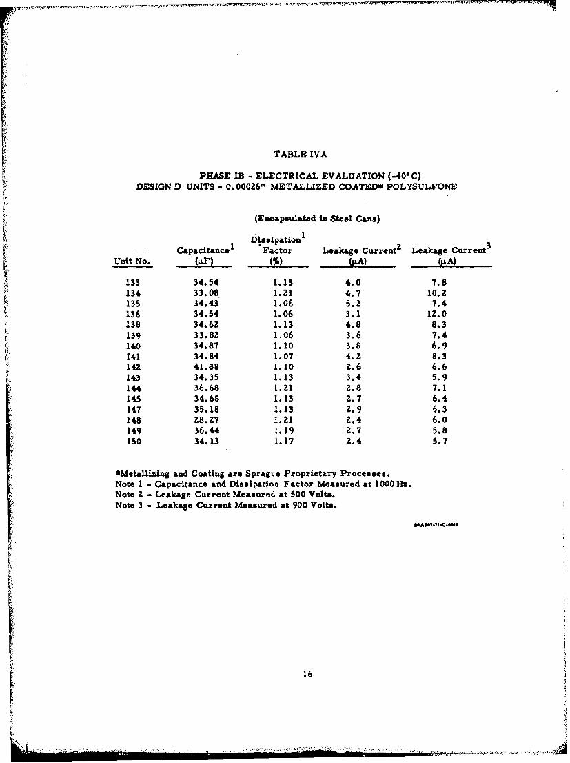
TABLE IVA
PHASE IB - ELECTRICAL EVALUATION (-40-C)DESIGN D UNITS - 0. 00026" METALLIZED COATED* POLYSULFONE
(Encapsulated in Steel Cans)
Iiissipation3CapacitanceI Factor Leakage Current2 Leakage Current
Unit No. 4%fl MJ } ..
133 34.54 1.13 4.0 7.8134 33.08 1.21 4.7 10.2135 34.43 1.06 5.2 7.4136 34.54 1.06 3.1 12.0138 34.62 1.13 4.8 8.3139 33.82 1.06 3.6 7.4140 34.87 1.10 3.8 6.9141 34.84 1.07 4.2 8.3142 41.38 1.10 z. 6 6.6143 34.35 1.13 3.4 5.9144 36.68 1.21 2.8 7.1145 34.68 1.13 2.7 6.4147 35.18 1.13 2.9 6.3148 28.27 1.zi Z.4 6.0149 36.44 1.19 2.7 5.8150 34.13 1.17 Z.4 5.7
*Metallizing and Coating are Spragt e Proprietary Processes.Note I - Capacitance and Dissipation Factor Measured at 1000Ha.Note 2 - Leakage Current Measure, at 500 Volts.Note 3 - Leakage Current Measured at 900 Volts.
16
. . , .• . ...... ,. ...... , - ,. r• •• •\ ,:,* • • • • • •• ' ". . . . '. . .
TABLE IVB
PHASE IB - ELECTRICAL EVALUATION (+ZSC)DESIGN D UNITS - 0.000Z6" MIETALLIZED COATED* POLYSULFONE
(Encapsulated in Steel Cans)
SDissipation3Capacitance Factor Leakage Current Leakage Current5
Unit No. J& A (tA)
133 34.57 0.75 43 67134 35.08 0.83 43 67135 34.46 1.06 41 58136 34.55 0.83 38 58138 34.63 0.75 38 56139 33.78 1.06 36 54140 34.98 1.06 35 541"41 34.82 0.83 34 50142 41.38 0.91 40 56143 34.37 1.05 24 50144 36.70 0.91 34 52145 34.55 0.98 36 62147 35.15 1. 06 36 62148 28.26 1.06 27 48149 36.50 0.98 33 58150 34.18 1.06 31 53
*Metallizing and Coating are Sprague Proprietary Processes.
Note I - Capacitance and Dissipation Factor Measured at 1000 Hz.Note 2 - Leakage Current Measured at 500 Volts.Note 3 - Leakage Current Measured at 900 Volts.
i 17
I6
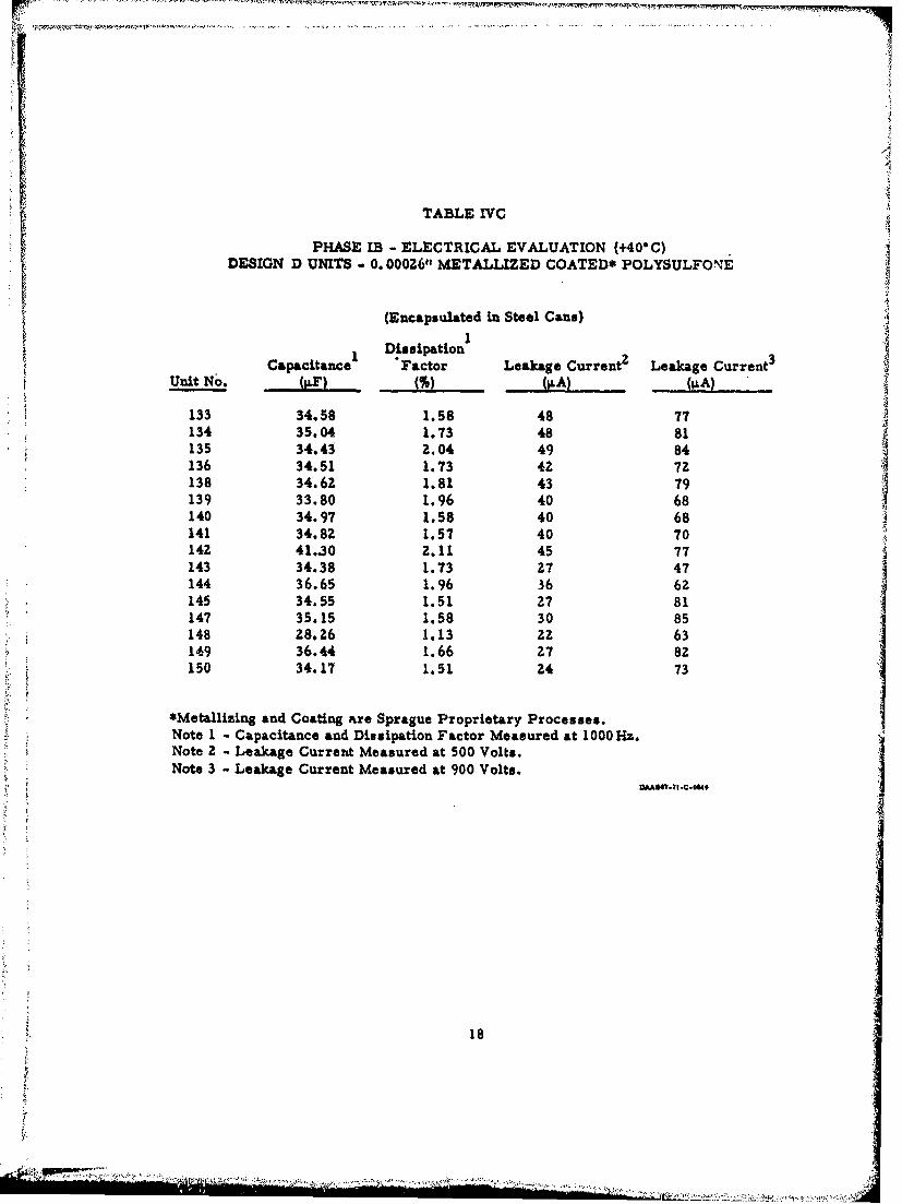
TABLE YVC
PHASE IB - ELECTRICAL EVALUATION (+40- C)DESIGN D UNITS - 0. 00026" METALLIZED COATED* POLYSULFONE
(Encapsulated in Steel Cans)
Dissipation1I
CapacitanceI Factor Leakage Currentz Leakage Current 3
Unit NO. (PS M(IA)([A
133 34.58 1.58 48 77134 35.04 1.73 48 81135 34.43 2.04 49 84136 34.51 1.73 42 7Z138 34.62 1.81 43 79139 33.80 1.96 40 68140 34.97 1.58 40 68141 34.82 1.57 40 70142 41.30 2.11 45 77143 34.38 1.73 27 47144 36.65 1.96 36 62145 34.55 1.51 27 81147 35.15 1.58 30 85148 28.26 1.13 22 63 I149 36.44 1.66 27 82150 34.17 1.51 24 73
*MetaUizing and Coating are Sprague Proprietary Processes.Note 1 - Capacitance and Dissipation Factor Measured at 1000 Hz.Note 2 - Leakage Current Measured at 500 Volts.Note 3 - Leakage Current Measured at 900 Volts.
18
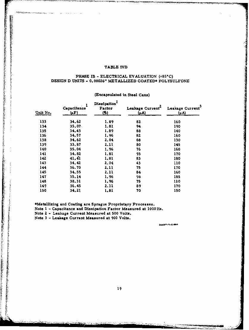
TABLE IVD
PHASE IB - ELECTRICAL EVALUATION (+85-C)DESIGN D UNITS - 0. 00026" METALLIZED COATED* POLYSULFONE
(Encapsulated in Steel Cans)
i ~Dissiparthio
Capacitance1 Factor Leakage Current2 Leakage Current 3
Unit No. (LF) ( LA.) (v.A)
133 34.62 1.89 8Z 160134 35.07 1.81 94 190135 34.43 1.89 88 140136 34.57 1.96 82 160138 34.62 2.04 68 130139 33.87 2.11 80 145140 35.04 1.96 76 160141 34.8Z 1.81 93 170142 41.41 1.81 83 180143 34.42 2.04 43 110144 36.70 2.11 75 170145 34.55 2.11 84 160147 35.14 1.96 98 185148 38.31 1.96 75 110149 36.45 2.11 89 170150 34.21 1.81 70 150
*Metallizing and Coating are Sprague Proprietary Processes.Note I - Capacitance and Dissipation Factor Measured at 1000 Hz.Note Z - Leakage Current Measured at 500 Volts.Note 3 - Leakage Current Measured at 900 Volts.
19
. .+ • , - -, . - +

TABLE VA
PHASE IB - ELECTRICAL EVALUATION (-400C)DESIGN E 0. 00027" METALLIZED COA TED* PETP SILICONE OIL IMPREGNATED
(Encapsulated in Steel Cans)
Dissipationi Leakage Current Leakage Current
-Unit Capacitancel Factor at 500 VDC at 900 VDCNo. (RF) M..Io . . (IxA) ,(IAA)
77 32.30 1.23 0.14 0.3478 32.80 1.25 0.14 0.4379 33.20 1.25 0.13 0.3880 32.40 1.26 0.12 0.3081 33.20 1.28 0.13 0.8082 34.40 1. 29 0.13 0.3583 32.30 1.28 0.11 0.3584 32.20 1.28 0.11 0.3085 33.20 1.28 0.10 0.3286 34.70 1.26 0.12 0.3187 33.80 1.27 0.13 0.3588 32.30 1.26 0.14 0.3589 33.10 1.27 0.14 0.3390 33.20 1.23 0.15 0.3191 32.10 1.25 0.15 0.2892 32.50 1.25 0.14 0.4393 33.20 1.25 0.13 0.2394 33.20 1.25 0.12 0.2995 32.90 1.27 0.13 0.27
*Sprague ProprietaryNote 1 - Capacitance and Dissipation Factor measured at 1000Hs
2C
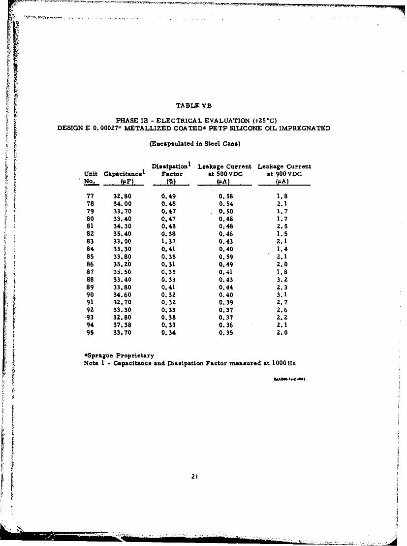
TABLE VB
PHASE I - ELECTRICAL EVALUATION (+25"C)DESIGN E 0. 00027" METALLIZED COATED* PETP SILICONE OIL IMPREGNATED
(Encapsulated in Steel Cans)
Dissipation1 Leakage Current Leakage Current
Unit Capacitancel Factor at 500 VDC at 900 VDCNo. Jftlr Jýt (ILA)
77 32.80 0.49 0.58 1.878 34.00 0.48 0.54 2.179 33.70 0.47 0.50 1.780 33.40 0.47 0.48 1.781 34.30 0.48 0.48 2.582 35.40 0.38 0.46 1.583 33.00 1.37 0.43 2.184 33.30 0.41 0.40 1.485 33.80 0.38 0.59 2.186 35.20 0.31 0.49 2.087 35.50 0.35 0.41 1.888 33.40 0.33 0.43 3.289 33.80 0.41 0.44 2.390 34.60 0.32 0.40 3.191 32.70 0.32 0.39 2.792 33.30 0.33 0.37 2.6•93 32.80 0.38 0.37 2.294 37.38 0.33 0.36 2.195 33.70 0.34 0.35 2.0
*Sprague ProprietaryNote 1 - Capacitance and Dissipation Factor measured at 1000 Hz
21~
.................................................. ,..-

TABLE VC
PHASE IB -ELECTRICAL EVALUATION (+40"C)DESIGN E 0. 00027" METALLIZED COATED* PETP SILICONE OIL IMPREGNATED
(Encapsulated in Steel Cans)
tDissipationI Leakage Current Leakage CurrentUnit Capacitancel Faitor at 500 VDC at 900VDCNo_..=. (,,F) M% (,A . ... 0A)
"77 32.80 0.49 1.3 3.578 34.00 0.48 1.2 3.679 33.70 0.47 1.2 4.880 33.40 0.47 1. 4.081 34.30 0.48 1.2 3.682 35.40 0.38 1.0 2.983 33.00 0.37 1.1 2.784 33.80 0.41 1.0 .2.785 33.80 0.38 1.0 2.486 35.20 0.31 0.9 2.687 35.50 0.35 0.9 2.688 33.40 0.33 1.1 4.189 33.80 0.41 1.0 1.890 34.00 0.32 0.7 2.291 32.70 0.32 0.8 1.692 33.30 0.33 1.0 2.093 32.80 0.28 0.9 2.294 32.80 0.33 0.7 2.695 33.20 0.34 1.2 1.9
*Sprague ProprietaryNote I - Capacitance and Dissipation Factor measured at 1000Hz
22t -I.49
I
'i 22

TABLE VD
PHASE IB - ELECTRICAL EVALUATION (+85'C)DESIGN E 0.00027" METALLIZED COATED* PETP SILICONE OIL IMPREGNATED
(Encapsulated in SteAl Cans)
Dissipation Leakage Current Leakage CurrentUnit Capacitance 1 FaCtor at 500 VDC at 900 VDCNo. (.) (,A) (ILA)
77 33.00 0.60 35.0 43.078 34.41 0.58 35.0 60.0
.79 34.20 0.58 31.0 38.0s0 33.40 0.60 32.0 75.081 34.30 0.58 32.0 57.082 35.70 0.60 28.0 38.083 33.50 0.60 3Z. 0 71.084 34.00 0.59 28.0 48.085 33.90 0.59 29.0 53.0,i 86 35.20 0.60 31.0 20.0• 87 35.90 0.60 32.0 60.0•: 88 34.20 0.62 28.0 62.089 34.10 0.64 34.0 41.090 34.40 0.62 26.0 43.091 33.00 *0.62 31.0 52.092 33.70 0.59 37.0 63.093 32.20 0.59 33.0 59.094 34.30 0.60 40.0 58.095 34.10 0.61 37.0 57.0
*Sprague ProprietaryNote I - Capacitance and Dissipation Factor measured at OOOHu
Z3
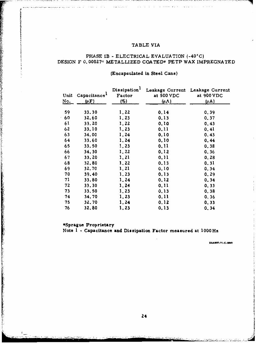
TABLE VIA
PHASE IB - ELECTRICAL EVALUATION (-40@C)DESIGN F 0. 00027'" METALLIZED COATED* PETP WAX IMPREGNATED
(Encapsulated in Steel Cans)
DissipationI Leakage Current Leakage CurrentUnit Capacitance Factor at 500 VDC at 900 VDCNo. 01F) M.. (A)
59 33.30 1.22 0.14 0.39- 60 32.60 1.23 0.13 0.37
61 33.20 1.22 0.10 0.4362 33.10 1.23 0.11 0.4163 34.00 1.24 0.10 0.4364 33.60 1.24 0.10 0.4465 33.50 1.23 0.11 0.38
K 66 34.30 1.22 0.12 0.3667 33.20 1.21 0.11 0.2868 32.80 1.22 0.13 0.3169 32.70 1.21 0.10 0.3470 39.40 1.23 0.13 0.2971 33.80 1.24 0.12 0.3472 33.30 1.24 0.11 0.3373 33.50 1.23 0.13 0.3874 34.70 1.23 0.11 O 3675 32.70 1.24 0.12 0.3376 32.80 1.23 0.13 0.34
*Sprague ProprietaryNote 1 - Capacitance and Dissipation Factor measured at 1000Hz
24
Ji--* .- , , -1'-- ~~

TABLE VIB
PHASE IB - ELECTRICAL EVALUATION (+25C)DESIGN F 0.00027,' METALLIZED COATED* PETP WAX IMPREGNATED
(Encapsulated in Steel Cans)
U Dissipation1 Leakage Current Leakage Current
Unit Capacitance Factor at 500 VDC at 900 VDC"" No. (Pf) 0q) IiA) iA)
59 34.50 0.42 0.63 2.7f 60 33.60 0.50 0.66 2.7
61 34.20 0.50 0.58 2.462 34.20 0.49 0.57 2.463 35.20 0.50 0.57 2.364 34.60 0.48 0.52 2.565 34.70 0.50 0.48 2.266 35.20 0.48 0.46 2.167 34.20 0.49 0.43 2.068 34.00 0.48 0.40 1.769 33.20 0.51 0.38 1.770 35.40 0.50 0.37 1.771 35.20 0.50 0.36 1.672 34.00 0.48 0.81 2.373 34.10 0.47 0.72 2.3
A 74 34.50 0.47 0.68 2.275 33.70 0.47 0.66 2.276 33.70 0.49 0.61 1.9
*Sprague Proprietary
Note 1 - Capacitance and Dissipation Factor measured at 1000Hz
25
- - : : • | i • : .. .- • , : • : • -: , . :- . : . .. .. . •. .. .

TABLE VIC
PHASE IB - ELECTRICAL EVALUATION (+406C)DESIGN F 0. 00027" METALLIZED COATED* PETP WAX IMPREGNATED
(Encapsulated in Steel Car.s)
"Dissipation1 Leakage -L ent Leakage CurrentUnit Capacitance Factor at 500 VDC at 900 VDCNo. (RF) (0/0 (RA) (IiA)
59 34.70 0.43 2.2 3.860 33.40 0.46 2.1 3.561 34.40 0.47 2.1 3.762 34.50 0.47 1.8 3.463 35.30 0.47 1.8 3.364 34.80 0.47 1.8 3.165 34.80 0.49 1.7 3.166 35.40 0.47 1.6 2.867 34.20 0.46 1.5 2.668 34.50 0.48 1.4 2.369 33.60 0.49 1.3 2.370 35.50 0.50 1.3 2.371 35.10 0.48 1.3 2.472 34.00 0.48 1.2 3.073 34.20 0.48 1.9 5.174 34.60 0.49 1.9 4.575 33.80 0.49 1.9 5.176 33.80 0.50 1.6 4.2
*Sprague ProprietaryNote I - Capacitance and Dissipation Factor measured at 1000 Hz
26
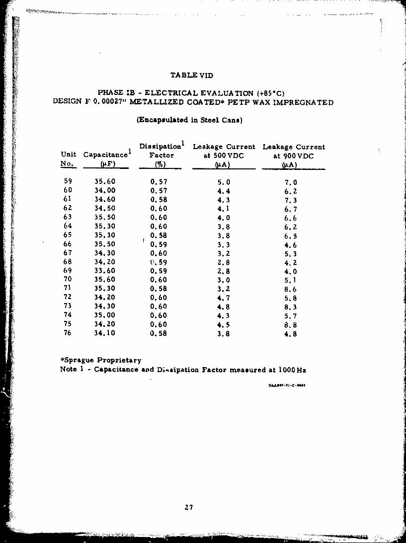
TABLE VID
PHASE IB - ELECTRICAL EVALUATION (+85"C)DESIGN F 0. 000271, METALLIZED COATED* PETP WAX IMPREGNATED
(Encapsulated in Steel Cans)
DissipationI Leakage Current Leakage CurrentL Unit Capacitance Factor at 500 VDC at 900 VDC
No. (1F) o(IA) (IA)
59 35.60 0.57 5.0 7.060 34.00 0.57 4.4 6.261 34.60 0.58 4.3 7.362 34.50 0.60 4.1 6.763 35.50 0.60 4.0 6.664 35.30 0.60 3.8 6.265 35.30 0.58 3.8 6.366 35.50 0.59 3.3 4.667 34.30 0.60 3.2 5.368 34.20 v.59 2.8 4.269 33.60 0.59 2.8 4.070 35.60 0.60 3.0 5.!71 35.30 0.58 3.2 8.672 34.20 0.60 4.7 5.873 34.30 0.60 4.8 8.374 35.00 0.60 4.3 5.775 34.20 0.60 4.5 8.876 34.10 0.58 3.8 4.8
*Sprague ProprietaryNote I - Capacitance avd Diftsipation Factor measured at 1000Hz
Z7

ILIICd/
00
c41
VC,,
F-I I; -F 1 44
Ti)4
28d
lip
~"AKTT:
.~ 1. 10.~ - - .:.
LI
ft .. 7T~~~~~~~~~47~t-T r t . .- * .----..-.--.-j
.ý CtI
UN v
.LCL
v 0
4) 4)
41 _
fW- .1-
LAO
300

00.
4) -
j 3't
LM
ce 0
a 0 -UL.± .* 2+xrjA '1,0 So 0
- - - - 144
- 00
0 41
4- - . . . . .
(a uI
ali a)Nvjjviv0
32

3IZi
Design C - 0.00oz6" I ___
------ Metallized Coated*_ . .- -Polycarbonatee. \
00U ... 1 *. .
Design F -0.00027" 1"MAetallized Coated*' Deeigri D - 0.00027"PETP Wax ... Coaed
-1 rgatd----- Polysulfone
US-DesignE - 0.00027"
,•',/'M Metallized Coated*PETP Silicone Oil
S.2 - ........ Impregnated ..
Design A * 0.00027" -'
Metallized Coated*-3 7/. PETP
-4 ./- ...*Sprague Proprietary
-40 -'0 iO 40 60 80 100TEMPERATURE "C
OAAS@1?I. |-C-@04
Percentage Capacitance Change vs Temperature
Figure 7
333 '

TABLE VII
BREAKDOWN VOLTAGE (ROOM TEMPERATURE)
Design A, 0. 000Z7" Metallized Coated* PETP
Unit No. Breakdown Voltage (VDC)
1 1400
Z 1300
3 15004 14005 1500
6 1300
Design C, 0. 000Z6" Metallized Coated* Polycarbonate
1 1500
Z 1400
3 1300
4 1500
5 1400
6 1400
Design D, 0.00027" Metallized Coated* Polysulfone
1 1300
2 1400
3 1200
4 1300
5 1500
6 1200
Design E, 0. 00027" Metallized Coated* PETP
(Silconc Oil Impregnated)1 15002 14003 1500
4 1500
5 1400
6 1600
Design F, 0. 00027" MetallIzed Coated* PETP
(Barcco Wax Impregnated)
1 1600
Z 1600
3 1500
4 1600
5 1400
6 1600
*Sprague Proprietary
34
..................................... -C,<~- L

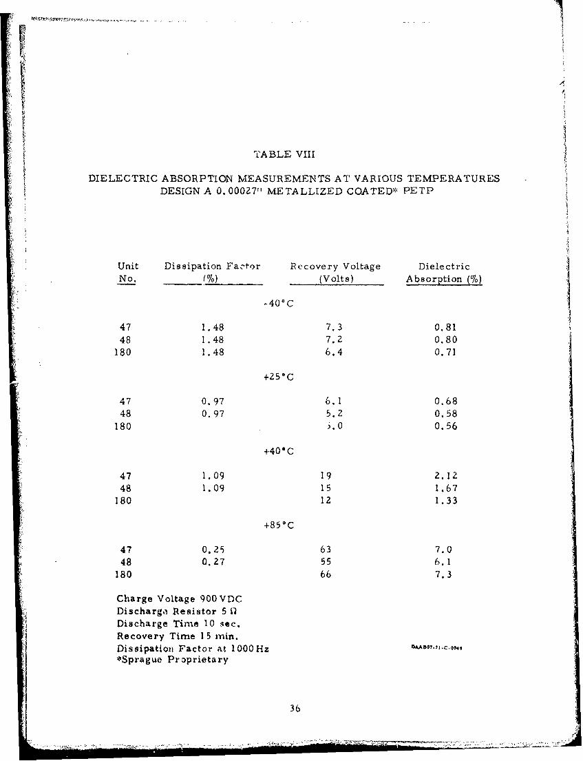
5. Dielectric Absorption
A sample of each design was tested for dielectric absorption.The results of these tests are tabulated in Tables VIII - XII. Thedielectric absorption measurements were made in accordance withMiL-C-19978C paragraph 4.7.15. The data indicate that there isa small decrease in dielectric absorption between -40 0 C and +25OCand a large increase in dielectric absorption between 25°C and 85°C.
Another point is that the dielectric absorption of the impregnatedcoated PETP units is less than that of the dry PETP units. Foruncoated PETP the reverse is true.
6. Test Equipment
It was necessary to design and build special test equipment
capable of charging and discharging 32p.F at 900V ten times persecond because of the high repetition rate required by this contract.It was decided to build six test units utilizing conventional thyratrontube switching and one test unit employing a special SCR solid stateswitch. This test equipment is shown in Figure .3.
Safety features of this test equipment included automatic shut-off in case of test capacitor short; pre-setable counter, time delayrequired for thyratron tubes; and interlock on test chamber door.A three amp fuse was added to the transformer after one of thetransformers failed during use.
Each test set was a self-contained unit. The test voltage wasvariable from zero to 1200 volts peak and the repetition rate wasadjustable from one to over ten pulses per second. Because of the
high power requirements, special care was taken in the design andwinding of the high voltage transformers. The internal dischargecircuitry included a 30 4H coil and a one ohm non-inductive resistor.Charging voltage could be monitored on a peak reading voltmeter.
A pulse voltage divider, and pulse current monitoring jackswere provided on the front panel. Controls also included a five digitpre-setable panel-moutited counter to shut down the test station aftera predetermined number of charge-discharge cycles.
After completion of Phase II testing, it was decided that certain
modifications to the CADET III test equipment were necessary.
35
. . . . . . . . . . . . . . . .. . . . . . . . . . . . . . . . .. ... "..... . . .
i
p4
TABLE VIII
DIELECTRIC ABSORPTION• MEASUREMENTS AT VARIOUS TEMPERATURESDESIGN A 0. 00027"H METALLIZED COATED* PETP
Unit Dissipation Fator Recovery Voltage DielectricNo. (%) (Volts) Absorption (%)
-40°C
47 1.48 7.3 0.8148 1.48 7.2 0.80
180 1.48 6.4 0.71
+250C
47 0.97 6.1 0.6848 0.97 5.2 0.58
180 i. 0 0.56
+40'C
47 1.09 19 2.1248 1.09 15 1.67
180 12 1.33
+850C
47 0.25 63 7.048 0.27 55 6.1
180 66 7.3
Charge Voltage 900VDCDischarg, Resistor 5 QDischarge Time 10 sec.Recovery Time 15 rain.Dissipation Factor at 1000 fHz*Sprague Proprietary
36

TABLE IX
DIELECTRIC ABSORPTION MEASUREMENTS AT VARIOUS TEMPERATURESDESIGN C 0.000261, METALLIZED COATED* POLYCARBONATE
Unit Dissipation Factor Recovery Voltage Diele ctricNo. (%) (Volts) Absorption.)
-400C
121 0.48 5.7 0.63125 0.43 5.5 0.61126 0.48 5.6 0.62
+Z50C
121 0.48 3.4 0.38125 0.45 5.4 0.60126 0.47 5.7 0.63
+40°C
121 0.45 5.5 0.61IZ5 0.42 16 1.78126 0.45 "5 1.67
+850c
121 0.40 38 4.2125 0.41 30. 3.3126 0.42 30 3.3
Charge Voltage 930VDCDischarge Resistor 50Discharge Time 10 sec.Recovery Time 15 min. •,8,.,Dissipation Factor at 1000Hz
*Sprague Proprietary
37
7 7_
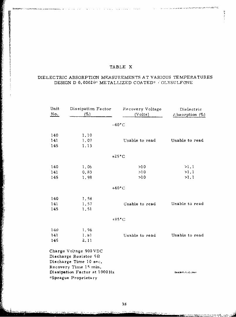
TABLE X
DIELECTRIC ABSORPTION MEASUREMENTS AT VARIOUS TEMPERATURESDESIGN D 0.00026t METALLIZED COATED' OLYSULFONE
Unit Dissipation Factor Recovery Voltage DielectricNo. (%) (Volts) P.bsorption (%)
-400C
140 1.10141 1.07 Unable to read Unable to read145 1.13
+250C
140 1.06 >10 >1. I141 0.83 >10 >1.1145 1.98 >10 >1.1
+400 C
140 1.58141 1. 57 Unable to read Unable to read145 1.51
+850C
140 1.96141 1., hi Unable to read Unable to read145 2.11
Charge Voltage 900VDCDischarge Resistor 50lDischarge Time 10 sec,Recovery Time 15 min.Dissipation Factor at 1000lhz
."Sprague Proprietary
38

TABLE XI
DIELEC LRIC ABSORPTION MEASUREMENTS AT VARIOUS TEMPERATURESDESIGN E 0.00027" METALLIZED COATED* PETP
SILICONE OIL IMPREGNATED
Unit Dissipation Factor Recovery Voltage DielectricNo. (0o) (Volts) Absorption (0)
-40"C
77 1.23 6.6 0.7384 1.28 6.7 0.7585 1.28 6.8 0.75
+Z59C
77 0.49 3.8 0.4284 0.41 4.6 0.5185 0.35 4. Z 0.47
+400C
77 0.49 5.0 0.56
84 0.41 9.3 1.0385 0.38 7.7 0.85
+85*C
77 0.60 54 6.0
84 0.59 64 7.185 0.59 60 6.7
Charge Voltage 900 VDCDischarge Resistor 5(1Discharge Time 10 sec.
"Dissipation Factor at 1000Hz
*Sprague Proprietary
39

TABLE XII
DIELECTRIC ABSORPTION MEASUREMENTS AT VARIOUS TEMPERATURES
DESIGN F 0.00027" METALLIZED COATED* PETPWAX IMPREGNATED
Unit Dissipation Factor Recovery Voltage DielectricNo. (%) (Volts) Absorption (%)
-40°C
66 1.22 6.2 0.6969 1.21 7.1 0.7972 1. Z4 7.0 0.78
+250C
66 0.48 3.4 0.3869 0.51 3.6 0.4072 0.48 3.7 0.41
+40*C
66 0.47 4.8 0.5369 0.49 4. 0.5172 0.48 5.0 0.56
+85*C
66 0.59 63 7.069 0.59 55 6.172 0.60 66 7.3
Charge Voltage 900 VDCDischarge Resistor 5QDischarge Time 10 sec.Recovery Time 13 ra. min..? € •,Dissipation Factor at 1000Hz*Sprague Proprietary
40

Iwki
* t . % ~N
ld me9
FigQ?*
I 441

After approximately 20 million charge-discharge cycles, thethyratron tubes had aged to the extent that replacement was necessary.Since the test station of solid state design had performed flawlesslyfor more than 20 million charge-discharge cycles, and this was thesecond set of thyratron tubes, it was decided to convert the conven-tional test stations to solid state switching. This was accomplishedon a one-at-a-time basis, so that the testing schedule was not dis-rupted. It was also decided at this time to increase the range of thecounters by a factor of ten. Additional circuitry was added to thebasic counter circuit to accomplish this extension.
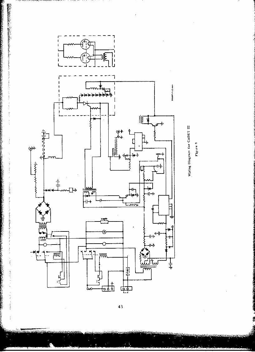
A schematic drawing of one of the test sets is shown in Figure 9.Figure 10 shows the CADET III test equipment and test oven.
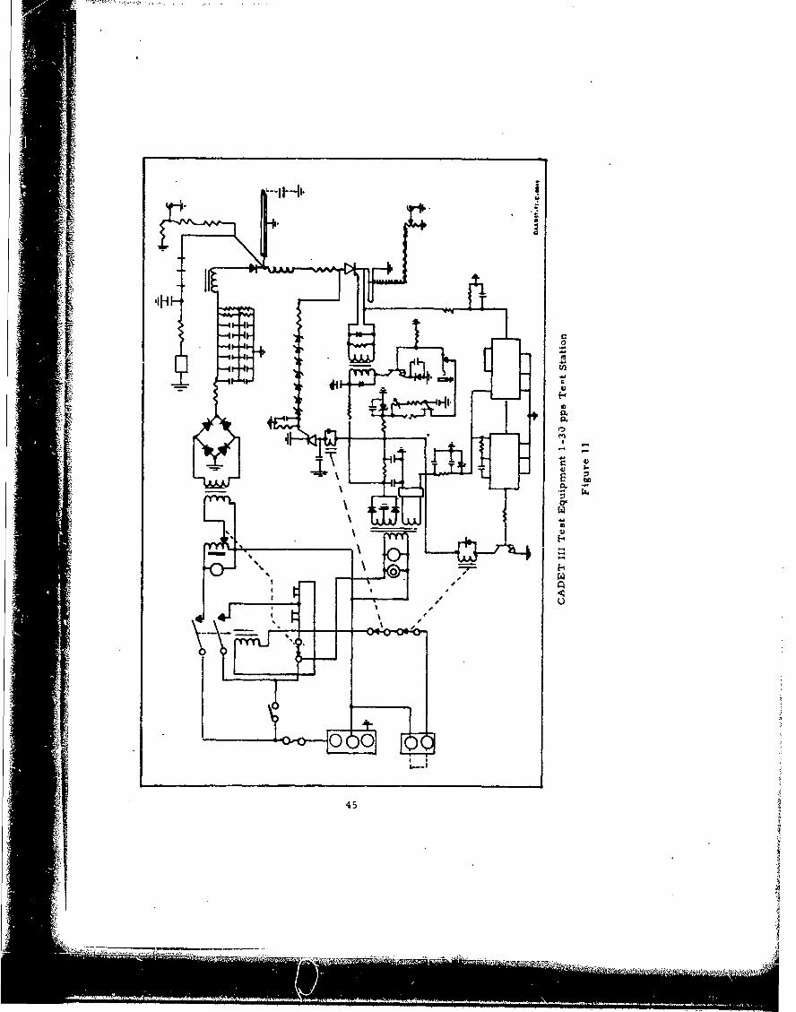
An eighth test station was constructed in an effort to providebackup capabilities in case of equipment failure, and to gain addi-tional information at higher repetition rates. This test station hadcapabilities of from 1 - 30 pps at voltages ranging from 200 - 1200
volts. A much larger transformer was required because of the muchhigher power requirements necessitated by the higher repetition rate.Also, a change in basic design was required by the high repetitionrate and resonant charging utilized. This test station also utilizedsolid state switching and all the safety features included in stationsone through seven as well as extended counter range. A drawingof the circuit is shown in Figure 11.
7. Testing and Evaluation
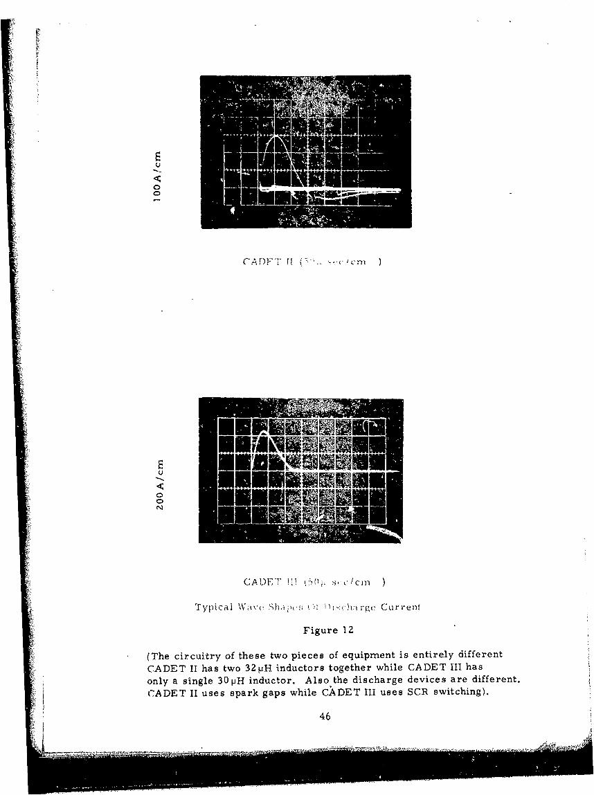
A six-piece sample of Designs A, C, D, E and F were charge-discharge life tested utilizing CADET III test equipment at 10 pps and40°C. Design C was partially tested on CADET II because CADET IIIhad not been completed. Design A was tested on both CADETS II andIII. Photographs showing a typical discharge current wave for both ICADETS II and III are shown in Figure 12. It is interesting to note
that while the duration of the current wave from CADETS II and IIIare about equal, the amplitude is considerably higher for CADET III.Because of differences in the circuitry, there is no undershoot onCADET III. The results of the initial charge-discharge testing aretabulated in Tables XIII - XVII. Tables XIII and XIIIA indicate t0 atthere is little difference in the results between the two pieces oftest equipment. Each group of capacitors had one failure. The unit(#51) which shorted on CADET III was a catastrophic failure causedby a rapid rise in the dissipation factor (DF). This caused the unit
42
... .. ...... .... .. " ".
4F
IHl
43 0

sawA
( .A I)E T III WVith ()\ (t D oorcaa Open
Fiiodr( 10
44
00
45.
0
CADE 1,5,fl1)
Typca -av ')-ýhi-EuCirFiur
0Tecrutyo hs w icso qimn setrl ifrn
(The circitrye ofp thesectwor piecsof tequipmaren isentirelyar different.
CADET II uses spark gaps while CADET III uses SCR switching).
46
VWL-J A-
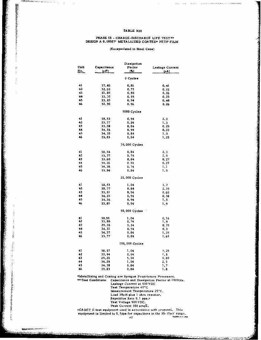
TABLE XiII
"PHASE lB - CHARGE-DISCHARGE LIFE TEST**DESIGN A 0.00027' METALLIZED COATED* PETP FILM
(Encapsulated in Steel Cans)
DissipationUnit Capacitance Factor Leakage Current
0 Cycles
41 37.40 0.86 0.41
42 32.60 0.73 0.2243 31.80 0.80 0.26
44 33.30 0.95 0.2545 33.20 0.94 0.4046 32.90 0.96 0. 26
5000 Cycles
41 38.53 0.94 2.042 33.77 0.84 1.3
43 33.58 0.84 0.2544 34.34 0.94 0.2245 34.38 0.84 1.046 33.83 0.84 1.25
10, 000 Cycles
41 38.54 0.84 2.342 33.77 0.74 2.043 33.60 0.84 0.27
44 34.36 0-94 0.2745 34.38 0.74 1.146 33.84 0.84 1.5
25, 000 Cycles
41 38.53 1.04 3.742 38.77 0.84 2.3543 33.51 0.94 0.60
44 34.35 0.94 0.3845 34.36 0.94 1.546 33.81 0.94 1I9
50, 000 Cycles
41 38.50 1.04 0.1642 33.80 0.74 1.943 29.28 5.34 0.75
v 44 34.31 0.94 0.345 34.37 0.84 1.2546 33.77 0.84 1.65
100, 000 Cycles
41 38.57 1.04 -0.2542 33.94 0.94 1.843 29.28 5.34 0.8044 34.28 1.04 2.545 34.38 0.84 1.746 33.83 0.84 1.8
*Metallizing and Coating are Sprague Proprietary Processes.**Test Conditions- Capacitance and Dissipation Factor at 1000Hz.
Leakage Current at 500 VDCTest Temperature 40"CMeasurement Temperature 25"C.Load 301iH plus I ohm resistor.Repetition Rate 0. I pps.+Test Voltage 900 VDC.
Peak Current 300 ampe.
+CADET It test equipment used in accordance with proposal. Thisequipment is limited to 0. Ipps for capacitors in the 30-.51iF range.
A..7...........,.......
W
TABLE XIIIA
PHASE IB - CHAR~GE -DISCHARGE LIFE TEST"DESIGN A 0.00027" METALLIZED COATED* PETP FILM
(Encapsulated in Steel Cans)
Dissipationunit Capacitance Iractor Leakage CurrentNo. 4I)(y)(j.&A)
0 Cycles
49 32. 82 0.97 0.3250 33.43 0.97 0.4Z51 3Z. 81 0.96 0352 32.2Z4 0.97 0.2Z453 31.05 0.96 0.2054 32. 53 0.96 0.2Z6
100,000 Cycles
49 33.87 0.94 1.0so 34.42 0.94 1.2551 34.00 0.65 1.3552 failed 37, 000 cycles.53 32.19 0.94 1.354 33.69 1.24 1.2Z5
Z00, 000 Cycles
a49 33.85 0.94 0.002250 34.43 0. 9Z Z.0551 34.00 0.94 1.6153 32.22 0.94 1.4554 33.68 1.24 2. 05
500,000 Cycles
49 31. 8Z 0.94 0.0850 34.37 1.04 0.0851 33.97 0.61 0.1053* 0.0019 3.64 0.12Z554 33.72 1.34 0.08
Unit No. 53 failed to charge after 241. 000 cycles.
1.000,000 Cycles
49 33. 8Z 0.94 0.002650 34.30 0.94 2.551* 34.04 0.94 8.654 33.50 2. 44 1.75
Unit No. 51 removed f rom test 901, 000 cycles.
1.500,000 Cycles
49 33.85 0.49 2.55s0 34.30 1.04 2. 954 Off scale ,removed from test 1. 028, 402 cycles.
a. 000, 000 Cycles
49 33.82 0.94 1.85s0 34.31 0.94 1.90
*Metalizizng and Coating are Sprague Proprietary Processes.**Test Conditions: Capacitance and Dissipation Factor at 1000 Hx.
Leakage Current at 500 VDC.

IITABLE XIV
PHASE IB - CHARGE-DISCHARGE LIFE TEST**DESIGN C 0.00026" METALLIZED COATED* POLYCARBONATE FILM
(Encapsulated in Steel Cans)
DissipationUnit Capacitance Factor Leakage CurrentNo. .LF) M.) , (IiA)
0 Cycles
109 34.65 0.70 0.38110 33.45 0.47 0.18111 32.90 0.45 0.16112 28.15 0.45 0.16113 34.45 0.56 0.30114 34.08 0.61 0.20
1000 Cycles
109 33.18 6.94 0.36110 33.39 0.32 0.12111 32.92 0.51 0.105112 28.18 1 04 0,11113 34.43 0.53 0.235114 34.04 0.45 0.22
10. 000 Cycles
109*** Off Scale (High DF)110 33.41 0.62 0.20ill 32.88 0.62 0,17112 28.18 0.62 0.17113 34.04 1.04 0.32
25.000 Cycles****
110 33.40 0.39 0. Z4111 32.*91 0.45 0.22112 28.16 0.32 0.25113 34.05 1.24 0.50114 34.41 0.57 0.38
50, 000 Cyclesa****
110 33.41 0.42 0.24Ill 33.90 0.45 0.23
. 28.11 0.40 0.25113 34.04 1.30 0.60114 34.43 0.6 0.45
100. 000 Cycles****
110 33.40 0.36 0.265Ill 32.97 0.41 0.2Z112 28.14 0.54 0.30113 34.08 1.04 2.0114 34.40 0.62 0. 32
*Metallizing and Coating are Sprague Proprietary Procebses.**Test Conditions: Capacitance and Dissipation Factor at 1000Hz.
Leakage Current at SOOVDC.Test Temperature 40*C.Measurement Temperature 25'C,Load 30iH plus I chin resistor.
+Repetition Rate 0. 1 pps up to and inmluding 10. 000cycles10 pps from 10, 000 cycles upward.
Test Voltage 900 VDIC.Peak Current 450 amps.
sa*st09 Failed 6469 Cycles.*s"*CADET Ill test equipment used from 10,001 to 100.000 'yti*'..
Repetition rate inc reased f romu 0. 1 pps til 0 ppN,eCADFT II test equipment wao himtted to 0. Ippa and CAI)ET It ti tequipmunt designed to run test at 10ppa in .accurdanct, with prop,,al.
49

TABLE XVPHASE IB - CHARGE-DISCHARGE LIFE TEST**
DESIGN F 0.00027- METALLIZED COATED* PETP WAX IMPREGNANT
(Encapsulated in Steel Cans)
DissipationUnit Capacitance Factor Leakage CurrentNo. (RF) M(IiA)
0 Cycles
59 34.50 0.42 0.6362 34.20 0.49 0. 5763 35.20 0.50 0.5767 34.ZO 0.49 0.4368 34.00 0.48 0.4071 35.20 0.50 0.36
5000 Cycles
59*** 25.54 6.14 Short
62 34.00 0.94 0.47563 34.84 1.04 0.2867 34.03 1.04 0.16568 33.68 1.04 0.1571 34.75 1.04 0.35
10,000 Cycles
62 33.99 0.94 0.5063 34.81 1.04 O. 2867 34.01 0.94 0.19568 33.69 0.94 0.004571 34.76 0.94 0.31
20, 000 Cyclesc
62 34.00 0.94 0.285
63 34.82 0.94 0.24567 34.00 0.94 0.1568 33.62 0.94 0.14571 34.73 0.94 0.335
40, 000 Cycles
62 34.01 0.94 0.2663 34.82 0.94 0.23567 33.99 0.94 0.13568 33.69 0.94 0.125-71.*** Cannot Read (Short)
100, 000 Cycles
6Z 34.03 0.94 0.4963 34.87 1.04 0.5067 34.02 0.94 0.2368 33.68 0.94 0.25
*Metallizing and Coating are Sprague Proprietary Processes.**Test Conditions: Capacitance and Dissipation Factor at 1000Hz.
Leakage Current at 500 VDC.Test Temperature 40*C.Measurement Temperature 25*C.Load 30dH plus I ohm resistor.
+Repetition Rate tOpp..Test Voltage 900 VDC.Peak Current 450 amps.
+CADET III test equipment used, (Dosiigind to run I Oppa repetition rate.)5e*59 Failed 3200 Cycles.404071 Failed 33. 800 Cycles.
SO

TABLE XVI
PHASE IB - CHARGE-DISCHARGE LIFE TEST**DESIGN E 0. 0002?" METALLIZED COATED* PETP SILICONE OIL IMPREGNATED
(Encapsulated in Steel Cans)
DissipationUnit Capacitance Factor Leakage Current
0 Cycles
78 34..,u 0.67 0.5480 33.40 0.97 0.4883 33.00 0.67 0.43
90 34.00 0.80 0.409z 33.30 0.77 0.3794 33.38 0.66 0.36
5000 Cycles
78 33.85 1.04 0.2580 34.20 0.32 0.001683 33.11 0.65 5.090 34.19 0.94 0.1492 33.51 0. 54 ".24594 34.15 0. ?4 O.29
I1, 000 Cycles
78 33.87 0.94 0.180 34.18 0.94 0.783 33.11 0.94 0.890 34.18 0.96 0.079z 33.57 0.94 0.1394 34.13 0.94 0.17
25. 000 Cycles
78 33*87 0.94 0.1480 34.23 1.04 0.1083 33.15 0.94 1.3590 34.25 0.94 0.17592 35.61 0.94 0.2594 34.17 0.57 0.315
50, 000 Cycles
78 33.88 0.65 0.2580 34.19 0.94 O.00283 33.15 0.84 0.9090 34.21 0.57 0.1592 33.58 0.84 0.2094 34.14 0.94 0.265
100, 000 Cycles
78 33.88 0.65 0.Z480 34.18 0.94 0.001583 33.15 0.84 0.9590 34.22 0.74 0.1692 33.59 0.84 o.2494 34.14 0.94 0. 25
*Meta~lzing and Coating are Sprague Proprietary Processes.**Test Conditions: Capacitance and Dissipation Factor at 1000Hz.
Leakage Current at 500 VDC.Test Temperature 40"C.Measurement Temperature 25"C.Load 301iH plua I ohm resistor.Repetition Rate 10 pps.Test Voltage 900VDC.Peak Current 450 amps, -
CADET III test equipment used.5I
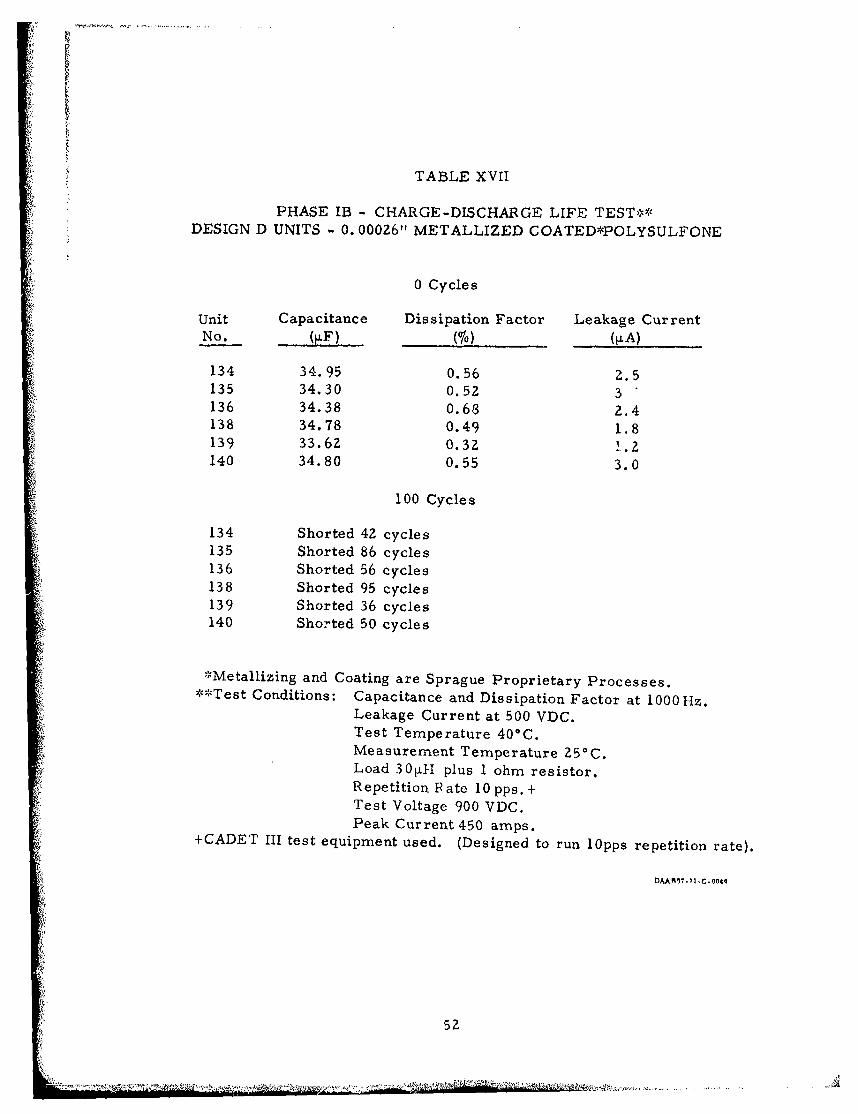
TABLE XVII
PHASE IB - CHARGE-DISCHARGE LIFE TEST**DESIGN D UNITS - 0. 00026" METALLIZED COATED*POLYSULFONE
0 Cycles
Unit Capacitance Dissipation Factor Leakage CurrentNo. (1,°) M....
134 34.95 0.56 2.5135 34.30 0.52 3136 34.38 0.68 2.4138 34.78 0.49 1.8139 33.62 0.32 1.2140 34.80 0.55 3.0
100 Cycles
134 Shorted 42 cycles135 Shorted 86 cycles136 Shorted 56 cycles138 Shorted 95 cycles139 Shorted 36 cycles140 Shorted 50 cycles
'Metallizing and Coating are Sprague Proprietary Processes.*-•Test Conditions: Capacitance and Dissipation Factor at 1000 Hz.
Leakage Current at 500 VDC.Test Temperature 40*C.Measurement Temperature 25C.Load 301±H plus 1 ohm resistor.Repetition Pate 10 pps. +Test Voltage 900 VDC.Peak Current 450 amps.
+CADET III test equipment used. (Designed to run i0pps repetition rate).
5lAAF7.7 I C-044
52

to heat which eventually caused the dielectric to melt. For the typeof units tested, the higher repetition rate of CADET III only seemsto accelerate the rate of failures. The higher repetition rate ofCADET III quickens the loss of connection between the electrode andend spray, thus raising the DF and causing the unit to heat. Thisheat rise can become so high that the dielectric can no longer with-stand the voltage and the unit faile. A photograph- showing loss ofmetal along the end connection edge of the film is shown in Figure 13.
After this limited testing the discharge life test data indicatethat Design E performed the best with no failure after 100, 000charge-discharge cycles. Designs A, C and F exhibited life testresults of approximately the same level of performance. This levelwas only slightly lower than that exhibited by Design E. Units ofDesign D failed before 100 cycles, again indicating dielectric of poorquality.
8. Design Selection
Design A was chosen over Design C for use in Phase II becausethe PETP is much easier to coat and metallize with consistently goodresults than the polycarbonate. The lower DF of the coated polycar-bonate compared to the coated PETP would not be a distinct advantageat a 10 pps repetition rate. At higher repetition rates, the coatedpolycarbonate should perform better than coated PETP. Design Fwas not chosen because the wax impregnation did not improve thebreak-lown voltage significantly and increased the weight. Also waxwould not conduct the heat out of the section as well as the siliconeoil.
Design D was eliminated because of the extremely poor dischargelife test results. Design B had previously been eliminated when unitsof this design would not withstand the necessary voltage.
9. End Connection
Considerable time was spent in an effort to develop bettermechanical and electrical connections between the electrode andthe metal end spray. Sections were rolled using 2" wide 0. 00052'metallized coated* PETP film. The sections were processed inthe normal manner with the exception of the end spray - lead
*'Metallizing and Coating are Sprague Proprietary Processes
53

LOSS OF METAL A.ND END CONNECTION
NO LOSS OF ENCD CONNECTION
COMPARISON OF FILM
WITH AND WITHOUT LOSS OF END CONNECTION
Figure 13
54

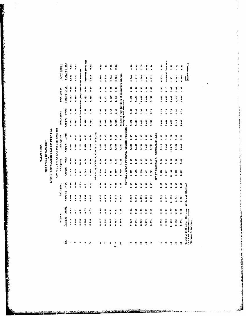
attachment method. All the experimental groups received 10, 000charge-discharge cycles at 2500 volts and 40°C or were removedfrom test due to excessive failures. The result of this testing isshown in Table XVIII. The data indicate that Spray Process C,control solder method gave the best results. Table XVIII alsoindicates a slight advantage using Spray Process A and lead attach-ment using Solder Process I.
10. Phase I Extension
It was decided to extend the testing on Design E units becauseof the extremely good initial results achieved with this design. Thiswas easily done because test equipment would be idle during theinitial stages of Phase II.
The extended life test data on Design E is shown in Table XIX.As the extended data indicate, Design E performed extremely well.
11. Phase II
A decision was made to include three end-connection g," -'tricvariations for both Design A (0. 00027" metallized coated*PL ;ndDesign E (0. 00027" metallized coated.•PETP, silicone oil] irr. ,..4ted)in the Phase II program. The three variations were:
Variation 1 - A different geometry with a longer electrodelength terminated with Spray Process C, Solder Process I.The purpose of these units was that the longer electrodelength would reduce the peak current per linear inch andextend the life of the end connection.
Variation 2 - Standard design with Spray Process C, SolderProcess I. This experimental group used the best sprayprocess from the end spray evaluation.
Variation 3 - Standard design with Spray Process A, SolderProcess I. This was the second best spray process of theend evaluation.
These capacitors were rolled and process.d using the sametechniques as in Phase I. The only deviation from the processes
used in Phase I was the variations in end spray. The 4" long unitswere encapsulated in aluminum cans while shorter units were en-capsulated in steel cans because aluminum cans were not availableat that time and the delay required to secure the cans was unnecessary.
""Metallizing and Coating are Sprague Proprietary Processes
__ -55
m• - .
a- a 4D 0 a n a .
0~0 0 c.ý ; C
46 0 n 9 # .
0 0
IL 0 C; C; a 0 o C
0 0 0 w 0 0 0 0 0 o o4 0
* 0~~~ C C ...... ---- C 0 0 0 - 0

JD v o6 0' 0 t- a'
u cc w o 0 0 0 m
co 4' r- a, 06 t- 0- t a ~ t
In - 0% 07 0 0
.14.
- a' E a
~ oa; 4 0 6 t- t- 0c6a 0 0
t- 0' - 0
0 00zu
0 l
0 co 0 2 0 0o 0 0 10
040'n'
C ' .. ' fn S Sto
In 0 0o 0 0ý 0 0 0 0
- 0 0 0 0o a 0, 0'c 0,
4r 0l 0' 0A 0In' 0 '4
lollo a,0t0.
coa
0' 0N en
10 57
m m cr r- 1aý, a 43a6 a co O co 11
0 0*( 4
'-I 0 A ~ ~ 2
0 00 a, t ~
0' 00 N C.C. 0 ~~ 0 0 o d ~ oco
4 4Z * w
oa 4
0 0t2 U) z .
0 13D0 000 c-. 4. 4 4'A
0 0 00 4 co -6 o ~ ~0 0
00"U) -0 0 en a ,0 ' 0 ' 0 0
a. 0 0
In LAt t- -0
4' ' o0 u) 4' -.oc co c* c z0'
.!~ 00
U>
u) E
06 v - 0
IV 0n
I- u08
UJ!?

LEGEND FOR TABLES XVIIIA - XVIIC
ReportHeading Actual Description
Control Spray Endspray applied in conventional state-of-the-artmanne r.
Spray Process A Endspray was applied at a distance of approxi-mately 8" between the spray nozzle and thetop of the section.
SSpray Process B Capacitor chilled to -55°C temperature beforespraying to prevent shrinkage of the film due to
* end spray heat.
Spray Process C Pure tin metal used as endspray material.
Spray Process D Four coats (approximately 1-3 mils each) ofnormal endspray formulation per end.
Spray Process E State-of-the-art vacuum deposition of aluminum* 'precoat prior to standard endspray.
Spray Process F A 450 angle was used in applying the spray toobtain maximum theoretical contact of sprayand electrode.
Control Solder Leads attached onto endspray using 60/40 tin/leadsolder with electric soldering iron (state-of-the-artI soldering procedure).
Solder Process 1 Pre-tinned leads attached to endspray using carbontip resistance soldering (no added solder).
Solder Process 2 Pre-tinned leads attached to endspray during theendspraying process using the heat of the meltingendspray to solder the lead to the endspray.
i"5
a2

TABLE XIX
CONTINUATION OF PHASE IB r-HARGE-DISCHARGE LIFE TESTINGDESIGN E - 0. 00027" METALLIZED COATEDI. PETPSILICONEOIL IMPREGNATED
DissipationUnit Capacitance Factor Leakage CurrentNo.. ((%) (PA)
0 Cycles
78 34.00 0.67 0.5480 33.40 0. 97 0.4883 33.00-. . 67 0.4390 34.00 0.80 0.409z 33.30 0.77 0.3794 33.38 0.66 0.36
5, 000 Cycles
78 33.85. 1.04 0.2580 34.20 0.32+ 0.0016+83 33.11 0.65 5.090 34.19 0.94 0.1492 33.51 0.94 0.24594 34.15 0.94 0.29
10,000 Cycles
78 33.87 0.94 0.180 34.18 0.94 0.783 33.11 0.94 0.890 34.18 0.96 0.079z 3 .57 0.94 0.1394 34.13 0.94 0.17
25. 0GO Cycles
78 33.87 0. 94 0.1480 34.23 1.04 0.1083 33.15 0.94 1.3590 34.25 0.94 0.17592 35.61 0.94 0.2594 34.17 0.57 0.315
50, 000 Cycles
78 33.88 0.65 0. Z580 34. 19 0.94 0.002+83 33.15 0.84 0,9090 34.21 0.57 0.1592 33.58 0.84 0.2094 34. 14 U. 94 0.265
100, 000 Cycles
78 33.88 0.65 0.2480 34.18 0.94 "0.0015+83 33.15 0.84 0.9590 34.23 0.74 0.1692 33.59 0.84 0.2494 34.14 0.94 0.25
60 Coaffact N*. flAA607i.U.C.OOq

TABLE XIX (CONTINUED)
CONT1INUATION OF PHASE IB CHARGE-DISCHARGE LIFE TESTEDDESIGN E - 0. 000Z7" METALLIZED COATED*PETP SILICONE OIL IMPREGNATED
DissipationUnit Capacitance Factor Leakage C,,r rentNo.
500, 000 Cycles
78 34.05 0.84 0.3280 34.20 0.99 0.7083 33.30 0.94 1.3090 34.55 0.84 0.2292 33. 6b 0.94 0.8094 34.10 0.94 0.55
1, 000, 000 Cycles
78 33.88 0.79 0.3280 34.10 0.70 0.7583 33.10 0.76 1.8090 34.10 0.70 0.2592 33.48 0.72 0.9894 34.04 0.70 0.50
2, 000, 000 Cycles
78 33.80 0.84 0.2880 34.00 0.84 0.6883 33.00 0.75 0.9090 34.00 0.79 0.2292 33.25 0.79 0.80
94 14.20 0.84 0.50
5, 000, 000 Cycles
78 33.75 0.74 0.34
80 34.09 0.74 0.921 83 34.12 0.74 1.40
90 34.06 0.74 1.3092 33.90 0.74 0.2694 36.04 0.74 0.88
10. 000, 000 Cycles
78 33.65 0.94 0.4880 33.84 0.84 0.9883 32.85 0.74 0.2790 33.78 0.65 0.2292 33.27 0.76 0.9494 35.68 0.74 0.68
*Sprague ProprietaryCapacitance and Dissipation Factor at 1000 HzLeakage Current at 500 VTest Temperature 40"C up to 100, 000 cycles 25*C after 100,000 cyclesMeasuring Temperature W5CRepetition Rate 1 OppsLoad 321.&H + 111 resistorCurrent z 450 anup.LReading error C ,,,a N. oaaN,.? .
61
The finished encapsulated units were cleared at 1000 volts at700 C. The number of audible clearing- was recorded. These data arerecorded in Table XX.
A sample of each design was measured for inductance. Thereadings are shown in Table XXI. The inductance measurementswere in the range of values expected for capacitors of this size andconstruction.
12. Testing and Evaluation
A sample of six units of each design variation was dischargelife tested for 10, 000, 000 charge-discharge cycles (at 10 pps and400C) or until failure. The results of this testing are shown in
Tables XXII - XXVII.
Two things are evident from these data:
Silicone oil impregnated units performed better thantheir dry (unimpregnated) counterparts.
Variation 1 units performed better than standarddesign units.
The reason that the silicone oil impregnated units performedbetter than the unimpregnated ones was not due to any appreciableincrease in dielectric strength caused by the impregnant, butrather from th'. silicone oil acting as a heat transfer medium toconduct heat away from the end connections and windings to bedissipated by the can.
The probable reason for the greater success of Variation 1capacitors was that the longer electrode length of these unitslowered the peak discharge current per unit of length to a valueat which a connection between the metallized electrode and endspray metal could be maintained.
On the basis of the discharge life test data, silicone oilimpregnated units of Variation I design were selected for use inPhase III.
62
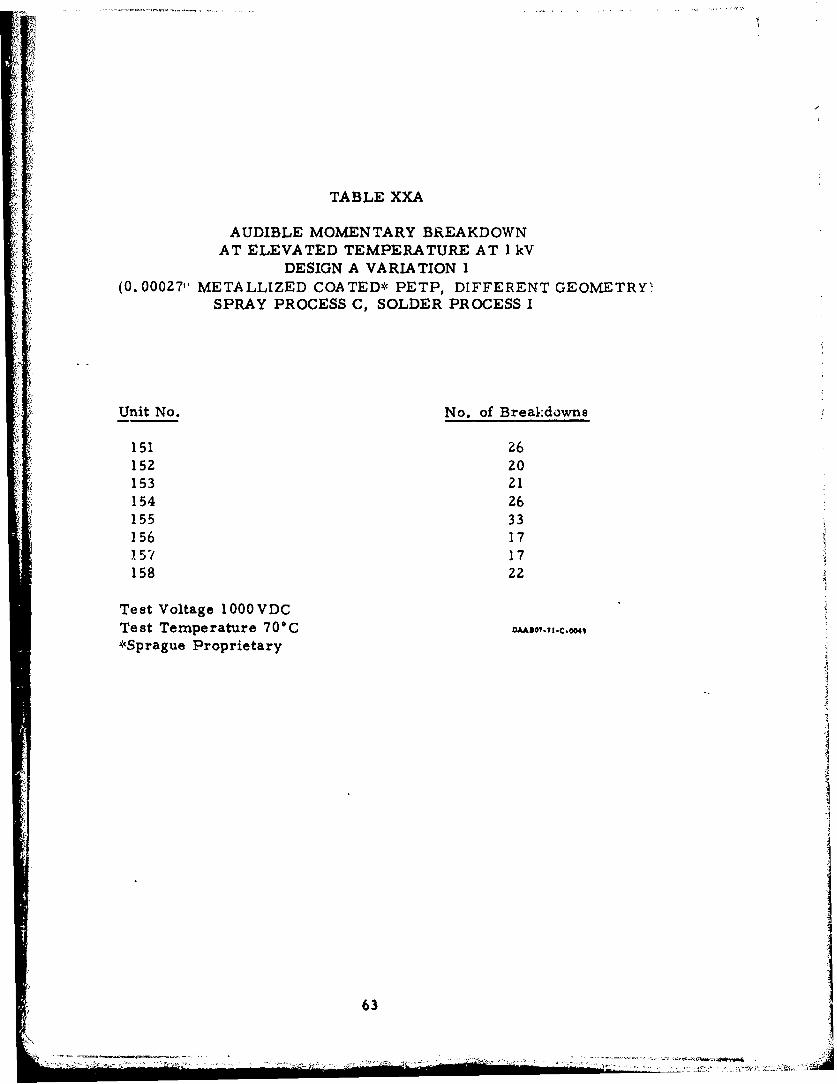
TABLE XXA
AUDIBLE MOMENTARY BREAKDOWNAT ELEVATED TEMPERATURE AT I kV
DESIGN A VARIATION I(0.00027, METALLIZED COATED* PETP, DIFFERENT GEOMETRY'
SPRAY PROCESS C, SOLDER PROCESS I
Unit No. No. of Breakdowns
151 26152 20153 21154 26155 33156 17i57 17158 22
Test Voltage 1000 VDCTest Temperature 70C ,*Sprague Proprietary
63
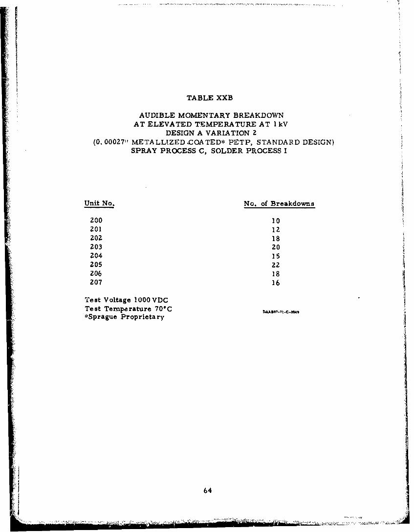
TABLE XXB
AUDIBLE MOMENTARY BREAKDOWNAT ELEVATED TEMPERATURE AT 1 kV
DESIGN A VARIATION 2(0. 00027" METALLIZED ZCOA TED* PETP, STANDARD DESIGN)
SPRAY PROCESS C, SOLDER PROCESS I
Unit No. No. of Breakdowns
-A 200 10201 12202 18203 20204205 22206 18207 16
Test Voltage 1000 VDCTest Tempe rature 701C*Sprague Proprietary
64
S~64
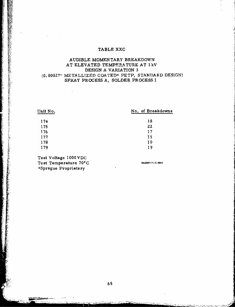
TABLE XXC
AUDIBLE MOMENTARY BREAKDOWNAT ELEVATED TEMPER-ATURE AT I kV
DESIGN A VARIATION 3(0. 000Z7" METALLIZED COATED* PETP, STANDARD DESIGN)
SPRAY PROCESS A, SOLDER PROCESS. I
Unit No. No. of Breakdowns
174 18175 22176 17177 15178 10179 19
Test Voltage 1000 VDCTest Temperature 70GC n"3o,.,,.c.•,,*Sprague Proprietary
I6
i~iII
65

TABLE XXD
AUDIBLE MOMENTARY BREAKDOWNAT ELEVATED TEMPERATURE AT 1 kV
DESIGN E VARIATION I(0.00027"1 METALLIZED COATED* PETP, DIFFERENT GEOMETRY,
SILICONE OIL IMPREGNATED)SPRAY PROCESS C, SOLDER PROCESS I
Unit No. No. of Breakdowns
180 10181 12182 16183 9184 11185 18
Test Voltage 1000 VDCTest Temperature 700C*Sprague Proprietary
66
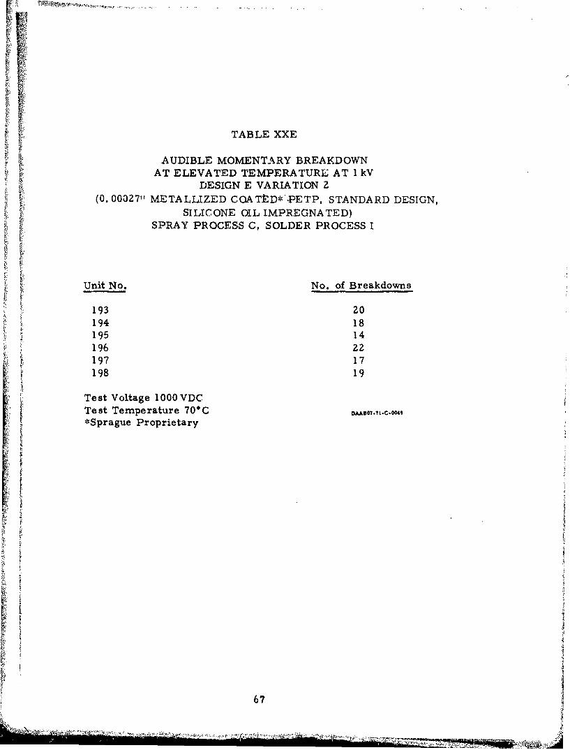
TABLE XXE
AUDIBLE MOMENTARY BREAKDOWNAT ELEVATED TEMPERATURE AT I kV
DESIGN E VARIATION 2(0. 00327" METALLIZED COATtD*'.PETP, STANDARD DESIGN,
SILICONE OIL IMPREGNATED)SPRAY PROCESS C, SOLDER PROCESS I
t Unit No. No. of Breakdowns
193 20194 18195 14196 22197 17198 19
Test Voltage 1000 VDCTest Temperature 700C DAA,0,.,zC.00,
*Sprague Proprietary
67
)A LA-

TABLE XXF
AUDIBLE MOMENTARY BREAKDOWNAT ELEVATED TEMPERATURE AT I kV
DESIGN A VARIATION 3
(0. 00027" METALLIZED COATED* PETP, STANDARD DESIGN,
SILICONE OIL IMPREGNATED)SPRAY PROCESS A, SOLDER PROCESS I
Unit No. No. of Breakdowns
186 10
187 15
188 16
189 19
190 27
191 18
192 Z2
Test Voltage 1000 VDCTest Temperature 70"C VA0,., .c.0,
*Sprague Proprietary
68

0 ý 1ý 6
u 140,
0 000 0 0 * 0000
cu 00000*oo0 000000 0a ;000000
C,
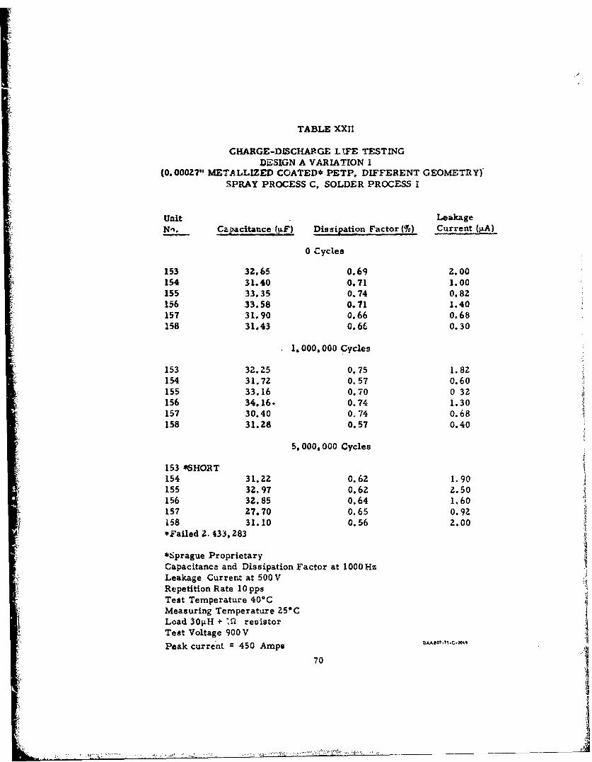
TABLE XXII
CHARGE-DISCHARGE LtFE TESTINGDESIGN A VARIATION I
(0.000Z7" METALLIZED COATED* PETP, DIFFERENT GEOMETRY)SPRAY PROCESS C, SOLDER PROCESS I
unit LeakageNn. Capacitance IF) Dissipation Factor (lo) Current (PA)
0 Cycles
153 32.65 0.69 2.00154 31.40 0.71 1.00155 33.35 0.74 0.82156 33.58 0.71 1.40157 31.90 0.66 0.68158 31.43 0.66 0.30
1.000,000 Cycles
153 32.25 0.75 1. 8z154 31.72 0.57 O.60155 33.16 0.70 0 32156 34.16. 0.74 1.30157 30.40 0.74 0.68158 31.28 0.57 0.40
5. 000, 000 Cycles
153 *SHORT154 31.22 0.62 1.90155 3Z.97 0.62 2.50156 32.85 0.64 1.60157 27.70 0.65 0.92158 31.10 0.56 2.00"FFailed Z. 433,283
*Sprague Proprietary
Capacitance and Dissipation Factor at 1000 HzLeakage Current at 500VRepetition Rate 10 ppsTest Temperature 40*CMeasuring Temperature 25CLoad 30p.H + 'a resistorTest Voltage 900 V
Peak current 450 Amps flo,.,,.C.oO,,
70
• " •; • " " "S -...... • " ', ...;Y •'":•L =° "•' ' " "• -" "'• "• • .--./l'•:,..,•.•'-' .• "- •.,--,• :,. ';•" ._ •' .
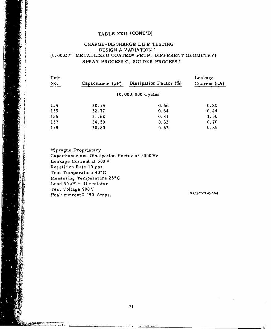
* TABLE XXII (CONT'D)
CHARGE -DISCHARGE LIFE TESTINGDESIGN A VARIATION 1
(0. 0007Z" METALLIZED COATED* PETP, DIFFERENT GEOMETRY)
SPRAY PROCESS C, SOLDER PROCESS I
Unit LeakageNo. Capacitance (RF) Dissipation Factor (16) Current (IiA)
10,000,000 Cycles
154 30. 5 0.66 0.80155 32.77 0.64 0.44156 31.62 0.81 3.50157 24.50 0.62 0.70158 30.80 0.63 0.85
-';Sprague ProprietaryCapacitance and Dissipation Factor at 1000HzLeakage Current at 500 VRepetition Rate 10 ppsTest Temperature 40*CMeasuring Temperature 25*CLoad 30 tH + 1WŽ resistorTest Voltage 900VPeak current - 450 Amps. DAAB•o7.71.c.0049
I71
•I'
•:...

TABLE XXIII
CHARGE-DICHARGE LIFE TESTINGDESIGN A VARIATION 2(0. 00027" METALLIZED COATED* PETP STANDARD DESIGN)3 SPRAY PROCESS CSOLDER PROCESS i
0 CyclesUnit Capacitance Dissipation Factor Leakage CurrentNo_:. , ) , % ... (A).
200 30.40 0.54 0.50201 29.00 0.64 0.80202 28.65 0.64 0.60203 29.98 0.64 0.80204 29.38 0.64 0.78205 30.45 0.66 0.90
1. 000, 000 Cycles
z00 Failed 238,950201 28.65 0.75 0.98202 £8.50 0.85 0.75203 Faild 938, 652204 29. 00 0.82.95"205 Failed 256, 322
5, 000, 000 Cycles
201 Failed 1, 098,506202 Failed 2, 568, 300204 Failed 1,687, 352
Capacitance and Dissipation Factor at 10001jz DAA8,e,.,,C.0 ,Leakage Current at 500 VTest Temperature 406CMeasuring Temperature 25"CRepetition Rate 10 ppsLoad 30tH + M • resistorTes•t Voltage 900 VPeak Current z 450A.*Sprague Proprittary 72

TABLE XXIV
CHARGE-DISCHARGE LIFE TESTINGDESIGN A VARIATION 3
(0.00027" METALLIZED COATED* PLTP. STANDARD DESIGN)SPRAY PROCESS A, SOLDER PROCESS I
Unit LeakageNo. Capacitance (gF) Dissipation Factor (%) Current (j±A)
0 Cycles
200 30.40 0.54 0.50201 29.00 0.64 0.80202 Z8.65 0.64 0.60203 Z9.98 0.64 0.80204 29.38 0.64 0.78205 30.45 0.66 0.90
1,000, 000 Cycles
200* Short301 26.65 0.75 0.98202 28.50 0. 8Z 0.75203+ OpenZ04 09.00 0.82 0.95205# Open*Failed 238,950+Failed 938, 65Z#Failed 256, 322
5,000, 000 Cycles
201** Short202++ Open204## Short**Failed 1,098, 506++Failed 2, 568,300
##Failed 1, 681, 352
Capacitance and Dissipation Factor at 1000 HzLeakage Current at 500 VTest Temperature 40°CMeasuring Temperature 25'CRepetition Rate 10 ppsLoad 30iH + IQ resistorTest Voltage 900 VPeak Current" 450A.*Sprague Proprietary73DAt.tC04
73...............
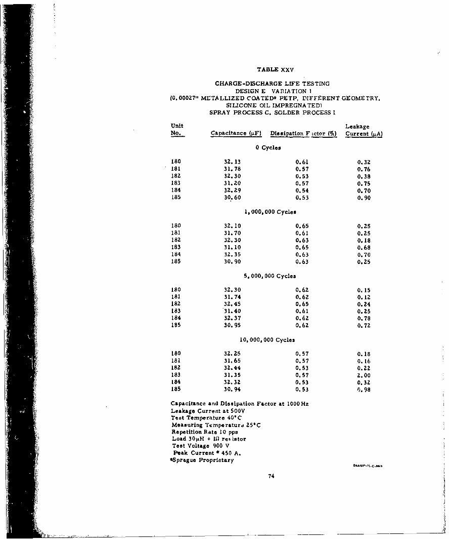
TABLE XXV
CHARGE-DISCHARGE LIFE TESTINGDESIGN E VARIATION I
(0. 00027" METALLIZED COATED* PETP, DIFFERENT GEOMETRY.SILICONE OIL IMPREGNATED)
SPRAY PROCESS C, SOLDER PROCESS I
Unit LeakageNo. Capacitance (iF) Dissipation F ictor (%) Current (gA)
0 Cycles
180 32.13 0.61 0.32181 31.78 0.57 0.76182 32.30 0.53 0.38183 31.20 0.57 0.75184 32.29 0.54 0.70185 30.60 0.53 0.90
1& 000, 000 Cycles
180 32.10 0.65 0.25181 31.70 0.61 0.25
182 32.30 0.63 0.18183 31.10 0.65 0.68184 32.35 0.63 0.70185 30.90 0.63 0.25
5, 000, 000 Cycles
180 32.30 0.62 0.15181 31.74 0.62 0.12182 32.45 O.65 0.24183 31.40 0.61 0.25184 32.37 0.62 0.78185 30.95 0.62 O.72
10, 000, 000 Cycles
L80 32.25 0.57 0.18181 31.65 0.57 0.16182 32.44 0.53 0.22183 31.35 0.57 2.00184 32.32 0.53 0.32185 30.94 0.53 r.98
Capacitance and Dissipation Factor at 1000HzLeakage Current at 500VTeet Temperature 40*CMeasuring Ternperaturd 25CRepetition Rate 10 ppsLoad 30jiH + 1fl resistorTest Voltage 900 VPeak Current * 450 A.
*Sprague Proprietary
74

TABLE XXVI
CHARGE-DISCHARGE LIFE TESTINGDESIGN E VARIATION Z
(0.000Z7" METALLIZED COATED* PETP STANDARD DESIGN
SILICONE OIL IMPREGNATED)SPRAY PROCESS C, SOLDER PROCESS I
0 Cycles
Unit Capacitance Dissipation Factor Leakage Current
No._:, SO V (0A)
193 34.17 0.69 0.40
194 34.09 0.74 0.38
195 35.75 0.74 0.38
196 34..J5 0.74 0.95
197 34.14 0.74 0.95
198 33.74 0.74 0.40
5, 000, 000 Cycles
193 34..10 0.70 0.30
194 Open 2,5 6 7 , 3 2 3
195 35.79 0.70 0.40
196 34.Z9 0.70 1.60
197 34.10 0.70 0.30
198 33.70 0.70 0.34
4. 10, 000, 000 Cyc.co
193 34.08 0.73 0.98
195 35.70 0.73 0.43
196 34.35 0.74 0.38
197 34.06 0.74 0. 52
198 33.67 0.74 0.Z8
Capacitance and Dissipation Factor at OOOHz
Leakage Current at 500 VDCiRepetition Rate 10 ppsTest Temperature 40*CMeasuring Temperature Z5*CLoad 30jiH plus I ohm resistorTest Voltage 900VDCPeak Current Z 450 amps.*Sprague Proprietary DA5o,.,.04o175

TABLE XXVII
CHARGE-DISCHARGE LIFE TESTINUDESIGN E VARIATION 3
(0. 00027? METALLIZED COATED* PETP, STANDARD DESIGN,SILICONE OIL IMPREGNATED)
SPRAY PROCESS A, SOLDER PROCESS I
Unit Leakage40o. CaFtance iFl Dissipation Factor Current (.A
0 Cycles
186 33.56 0.76 0.68187 39.43 0.74 1.50188 34.05 0.71 0.80190 33.71 0.74 0.40191 33.55 0.69 0.98192 35.22 0.74 0.40
1. 000, 000 Cycles
186 33.50 0.70 0.46187 34.40 0.71 0.30188 34.10 0.70 0.40190 33.65 0.73 0.60191 33.50 0.71 0.4019Z 35.20 0.69 0.60
5,000, 000 Cycles
186 33.72 0.70 0.23187 34.42 0.71 0.38188 34.88 0.69 0.35190* Open191 33.62 0.69 0.30192 35.25 0.69 0.45*Failed 3.226, 368
10. 000. 000 Cycles
186 33.56 0.68 0.26187 34.30 0.74 0.20188 33.95 0.74 0.50191 33.70 0.80 0.30192 35.15 0.81 0.24
Capacitance and Dissipation Factor at 1000HzLeakage Current at 500VTest Temperature 40*CRepetition Rate 10 ppsMeasuring Temperature 251"Load 304H + I10 resistorPeak Currents 450APeak Voltage 900V.*Sprague Proprietary 76 •,.c..,,

13. Phase III
Units of Design E Variation 1 were produced in the same manneras in Phase II with the exception that plated aluminum cans and coverswere used. The cans and covers were plated with electroless nickelfollowed by a hot tin dip. With the plating, the units could be hermeti-cally encapsulated using standard tin-lead solder. A comparisonamong the state-of-the-art metallized paper capacitor, the initialcontract design units and the final design is shown in Figure 14.
After initial electrical measurements shown in Table XXVIII,six capacitors were discharge life tested. Twelve additional capacitorswere shipped to the U. S. Army Electronics Command, Fort Monmouth,New Jersey. The results of this testing are shown in Table XXIX. Itcan be seen that only one unit of the six which were tested failed tomeet the 50, 000, 000 charge-discharge cycles objective. This unitwas removed from test after 10, 000, 000 charge-discharge cyclesbecause of loss of capacitance from an initial reading of 31.65 4F to19.Z254F after 10,000,000 charge-discharge cycles. It should bepointed out that this was not a catastrophic failure such as a shortor open but was still operable. The dissipation factor had also risento 3. 30%. It is interesting to note that the large loss of capacitanceand rise in dissipation factor occurred between 5, 000, 000 and10, 000, 000 discharge cycles. It should be noted that the capacitanceon this unit dropped about 6% between 0 and Z. 5 million cycles. Thisis a considerably higher capacitance drop than was exhibited by theother units. Because of this capacitance change, it may be possibleto screen out infant mortalities such as this unit by use of a burn-in.It appears that a burn-in of less than 1016 of the expected life couldeliminate possible early failures.
Apparently, new methods of measurements will have to bedevised to screen out early failures. However, on the basis ofpresent state-of-the-art capacitors, a failure at 10, 000, 000 charge -
discharge cycles could not be considered an early failure, especiallywhen the repetition rate of 10 pps is considered.
Late in Phase III, a new film (Polyvinylidene Fluoride) becameavailable in engineering sample quantities. This is an extrudedbiaxially oriented film with a dielectric constant of 11. 0. A sampleof the film was processed and capacitors were rolled. Because ofthe lirmited amount of film available, it was decided to roll capacitorsof only approximately 5 iF. The initial electrical measurements on
77

Vvs a1va'
(Left to Right) State-of-the-Art, Final Design~and Initial Design Capacitors
Figure 14
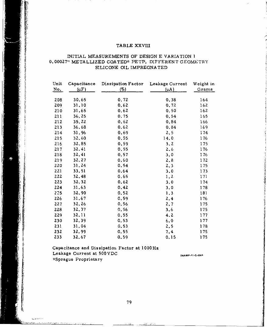
TABLE XXVIII
0. INITIAL MEASUREMENTS OF DESIGN E VARIATION I
S0. 00027" METALLIZED COATED* PETP, DIFFERENT GEOMETRYSILICONE OIL IMPREGNATED
Unit Capacitance Dissipation Factor Leakage Current Weight inNo. (f) (%) (pA) Grams
208 30.65 0.72 0.38 164209 31.10 0.62 0.7Z 162210 31.65 0.62 0.50 162211 36.25 0.75 0.54 165212 35.22 0.62 0.84 166213 36.68 0.62 0.84 169214 31.96 0.69 2.5 174215 32.60 0.55 14.0 176216 32.85 0.59 3.2 175217 32.41 0.55 2.6 176218 3Z.41 0.57 3.0 176219 32.27 0.60 2.8 172220 31.24 0.54 2.3 175221 33.51 0.64 3.0 173
222 32.48 0.65 1.z 171ZZ3 32.32 0.62 3.0 174224 31.63 0.42 3.0 178225 32.90 0.52 1.3 181226 31.67 0.59 2.4 176
27 32.26 0.56 2.7 175ZZ8 32.37 0.56 3.6 175229 32.11 0.55 4.2 177230 32.39 0.53 6.0 177231 31.04 0.53 2.5 178232 32.99 0.55 7.4 175233 32.67 0.59 0.15 175
Capacitance and Dissipation Factor at 1000HzLeakage Current at 500VDC D,•Ro,.,I.-..00*Sprague Proprietary
4 79
i *,*',

TABLE XXIX
CHARGE-DISCHARGE LIFE TESTINGDESIGN E VARIATION 1
0. 00027" 1METALLIZED COATED* PETP. DIFFERENT GEOMETRY,SILICONE OIL IMPREGNATED
0 Cycles
Unit Capacitance Dissipation Factor Leakage CurrentNo. (%) (pA)
208 30.65 0.72 0.38209 31.10 0.62 0.72210 31.65 0.62 0.50211 36.25 0.75 0.54212 35.22 0.62 0.84213 36.58 0.62 0.98
2, 500, 000 Cycles
208 31.75 0.68 0.40209 31.00 0.75 0.68210 30.66 0.68 0.75211 36.00 0.75 0.54212 35.20 0.60 0.80213 36.60 0.61 0.85
"5, 000, 000 Cycles
208 31.50 0.66 0.45209 30.90 0.76 0.75210 30.00 0.75 0.70211 36.50 0.76 0.60212 34.90 0.72 0.76213 36.50 0.69 0.85
10, 000, 000 Cycles
208 31.15 0.61 0.32209 30.62 0.61 0.18210 19.25 3.30 0.54211 36.00 0.75 0.68212 34.75 0.70 0.70213 36.40 0.69 0.80
80
"•.4
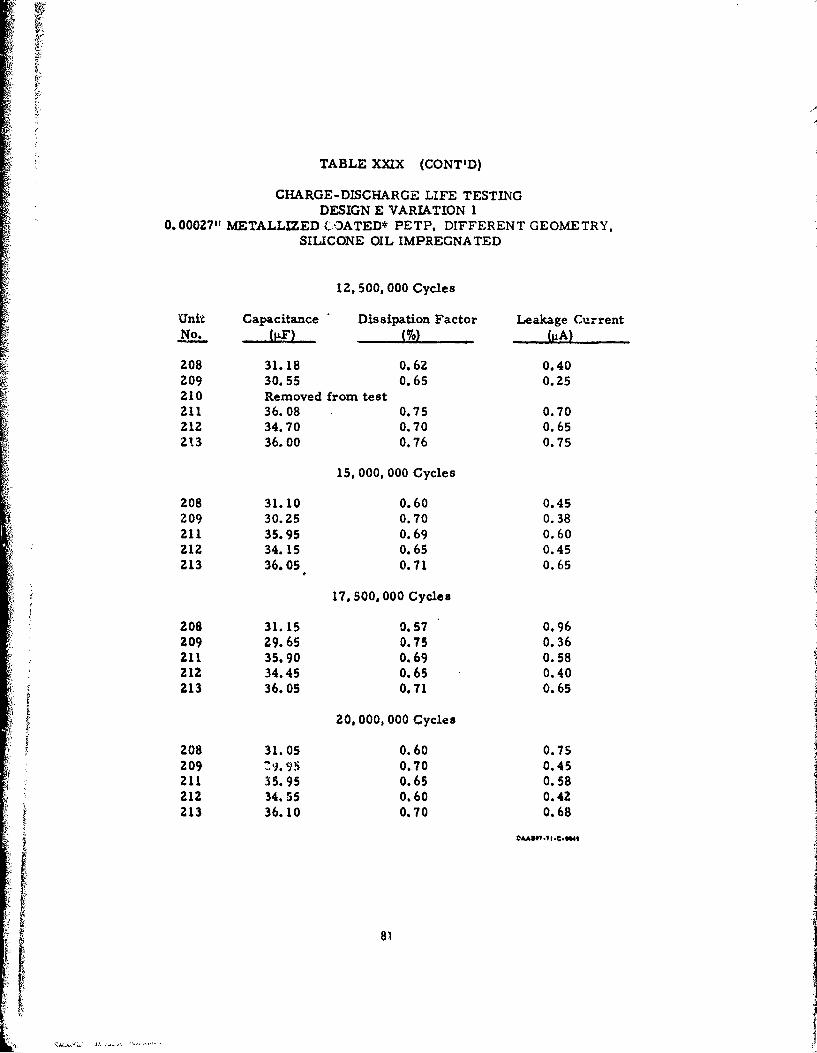
TABLE XXIX (CONT'D)
CHARGE-DISCHARGE LIFE TESTINGDESIGN E VARIATION 1
0. 00027" METALLIZED .OATED* PETP. DIFFERENT GEOMETRY,SILICONE OIL IMPREGNATED
12, 500, 000 Cycles
Unit Capacitance Dissipation Factor Leakage CurrentNo. (gA)
208 31.18 0.62 0.40209 30.55 0.65 0.25210 Removed from test211 36.08 0.75 0.70212 34.70 0.70 0.65213 36.00 0.76 0.75
15, 000, 000 Cycles
208 31.10 0.60 0.45209 30.25 0.70 0.38211 35.95 0.69 0.60212 34.15 0.65 0.45
213 36.05 0.71 0.65
17, 500, 000 Cycles
208 31.15 0.57 0.96209 29.65 0.75 0.36211 35.90 0.69 0.58212 34.45 0.65 0.40213 36.05 0.71 0.65
20, 000, 000 Cycles
208 31.05 0.60 0.75209 Z:.S56 0.70 0.45211 35.95 0.65 0.58212 34.55 0.60 0.42Z13 36.10 0.70 0.68
81

TABLE XXIX (CONT'D)
CHARGE-DISCHARGE LIFE TESTINGDESIGN E VARIATION 1
0.00027" METALLIZED COATED* PETP, DIFFERENT GEOMETRY,SILICONE OIL IMPREGNATED
22, 500, 000 Cycles
Unit Capacitance Dissipation Factor Leakage CurrentNo. ... (pA)
208 31.00 0.70 0.65209 29.75 0.69 0.80211 35.70 0.65 0.60212 35.50 0.70 0.45213 36.08 0.69 0.70
25, 000, 000 Cycles
208 31.05 0.70 0.70Z09 29.65 0.65 0.70211 35.10 0.75 0.6021Z 39.50 0.70 0.68213 35.95 0.75 0.80
27, 500, 000 Cycles
208 31.08 0.70 0.65z09 29.60 0.70 0.80210 35.10 0.70 0.60212 34.48 0.70 0.80213 35.60 0.80 0.65
30, 000, 000 Cycles
208 31.10 0.70 0.80209 29.55 1.70 0.80211 35.06 0.53 0.25212 34.40 0.71 1.00213 35.50 0.90 6.80
82AADe.t.C.004q
u8

TABLE XXIX (CONT°D)
CHARGE-DISCHARGE LIFE TESTINGDESIGN E VARIATION 1
0. 00027" METALLIZED COATED* PETP. DIFFERENT GEOMETRY.SILICONE OIL IMPREGNATED
32, 500, 000 Cycles
Unit Capacitance Dissipation Factor Leakage CurrentNo__. .... NA)}... . ( )(•
208 31.09 0.65 0.75209 29.05 1.60 0.60211 34.68 0.60 0.58212 34.00 0.63 0.60213 35.55 0.65 0.80
35, 000, 000 Cycles
Z08 31.00 0.60 0.80209 29.60 0.60 0.70211 34.75 0.62 0.65212 33.60 0.60 0.70213 35.50 0.60 0.85
37, 500, 000 Cycles
208 31.08 0.56 0.80209 29.50 0.66 0.88
S211 35.08 0.70 0.90212 32.56 0. 66 0.74213 35.60 0.50 0.80
40, 000. 000 Cycles
208 31.07 0.57 0.12209 29.44 1.75 0.82211 35.00 0.57 0.62212 35.25 0.57 0.62
28.86 0.57 0.50
83

TABLE XXIX (CONT'D)
CHARGE-DISCHARGE LIFE TESTINGDESIGN E VARIATION I
0. 00027" METALLIZED COATED* PETP. DIFFERENT GEOMETRY,SILICONE OIL IMPREGNATED
42, 500, 000 Cycles
Unit Capacitance Dissipation Factor Leakage CurrentNo. (%) (IA)
208 31.05 0.52 0.26209 29.35 1.60 0.80210 35.08 0.66 0.70211 35.30 0.60 0.68212 35.30 0.60 0.68213 27.65 0.60 0.58
45, 000, 000 Cycles
208 31.00 0.58. 0.60.209 29.30 1.50 0.85211 35.05 0.60 0.76212 35.50 0.58 0.46213 27.00 0.66 0.44
47, 500, 000 Cycles
208 31.00 0.58 0.25209 29.28 1.60 0.75211 35.30 0.60 0.80212 33.40 0.68 0.40213 26.08 0.58 0.60
50. 000, 000 Cycles
208 31.05 1.56 0.20209 29.25 1.74 0.82211 35.23 0.56 0.84212 33.35 0.66 0.22213 24.82 O.59 0.40
Capacitance and Dissipation Factor at 1000HzLeakage Current at 500 VDCRepetition Rate 10 ppsTest Temperature 40*CMeasuring Temperature 25 CLoad 30 g&H plus I ohm resistorPeak Current : 450 amps.*Sprague Proprietary
84

"] t
these units are shown in Table XXX. The leakage currents anddissipation factors are much higher for these capacitors than forany of the designs used in Phase I. This is due to the basic natureof the film and not because of any degrading of the film's propertiesdue to coating.
The electrical characteristics were measured at varioustemperatures. There was a tremendous capacitance loss at thelower temperatures which would necessitate a much larger sizeunit at room temperature to maintain a constant amount of energyat the lower temperature. Capacitance change vs. temperatureis shown in Figure 15.
These units failed before 500 charge-discharge cycles becauseof the high DF and high A.eakage currents on discharge life testing at10 pps.
Very late in Phase III the eighth test station of CADET III was2 received. Because of the lack of time very little data was gathered
with this unit. The results of the discharge life test at 30 pps areshown in Table XXXI. It iq interesting to note that the Design EVariation 1 type units performed well with only 1 failure in sixunits tested for 10, 000, 000 charge-discharge cycles.
85

TABLE XXXA
INITIAL ELECTRICAL RESULTS0. 00036" METALLIZED COATED'POLYVINYLIDENE FLUORIDE
Unit Capacitance Dissipation Factor Leakage CurrentNo. F (M°) ..
1 4.957 1.20 4.02 4.995 1.20 3.63 4.993 1.20 Short4 5.001 1.20 Short5 4.993 1.2 3.06 4.956 1.2 4.67 5.318 1.2 3.28 4.986 1.2 3.29 5.236 1.2 3.0
10 4.981 1.2 2.811 5.015 1.2 3.012 4.970 1.2 3.213 5.149 1.3 4.214 5.076 1.2 3.015 5.040 1.2 3.2"16 4.980 1.2 3.617 5.047 1.2 3.418 5.106 1.5 4.419 5.082 1.2 4.420 5.164 1.2 3.8
Capacitance and Dissipation Factor at 1000HzLeakage Current at 500VDC*Sprague Proprietary
86MDA O-?.C*0049
i: 86
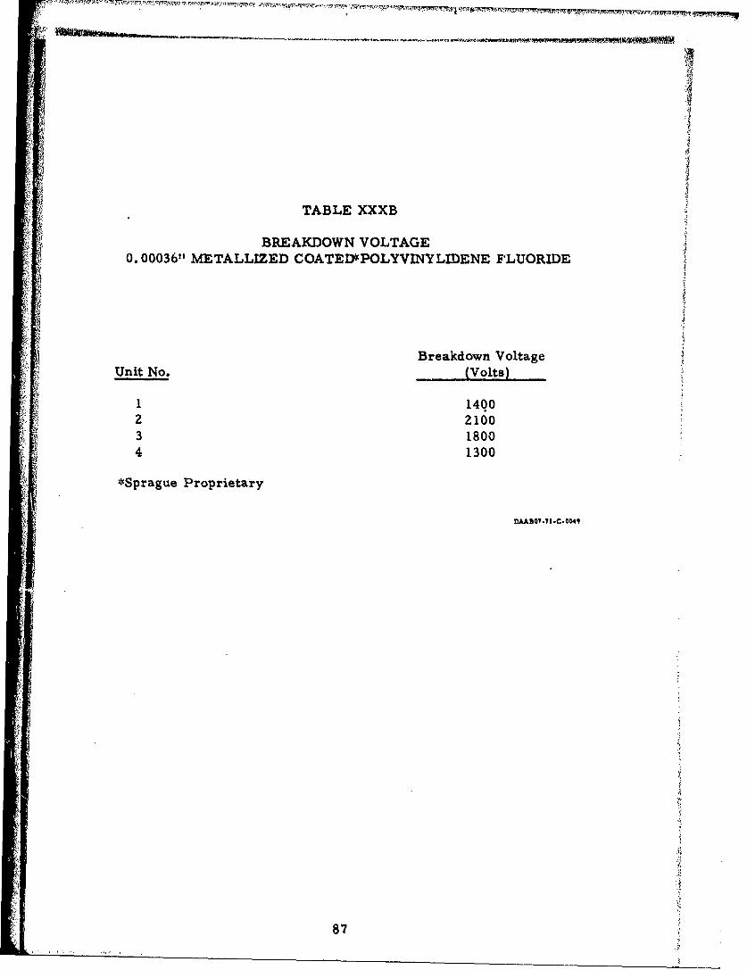
TABLE XXXB
BREAKDOWN VOLTAGE0. 00036" METALLIZED COATED'POLYVINYLIDENE FLUORIDE
i4
Breakdown VoltageUnit No. (Volts)
1 14002 21003 18004 1300
*Sprague Proprietary
DAABO1.1t-C.0041
87

TABLE XXXC
CAPACITANCE AND DISSIPATION FACTOR FOR VARIOUS FREQUENCY0.00036" METALLIZED COATED POLYVINYLMDENE FLUORIDE
Unit Capacitance Dissipation Factor Capacitance Dissipation FlactorNo_..., o
.1Hz 1. kHz
5 5.017 0.95 4.9516 1.169 Cannot Read 5.2040 12.90
16 4.9892 0.93 4.9282 1.1419 5.0920 0.95 5.0316 1.21
2kHz 5kHz
5 4.9373 1.37 4.9214 2.0849 5.1972 16.10 5.2167 29.405
16 4.9260 1.34 4.8980 1.9419 5.0173 1.51 5.0008 2.33
10 kHz
5 4.9362 3.089 5.3001 58.6
16 4.9094 2.9619 5. 0162 2.03
*Sprague Proprietary
DAADO??I .C.0049
88
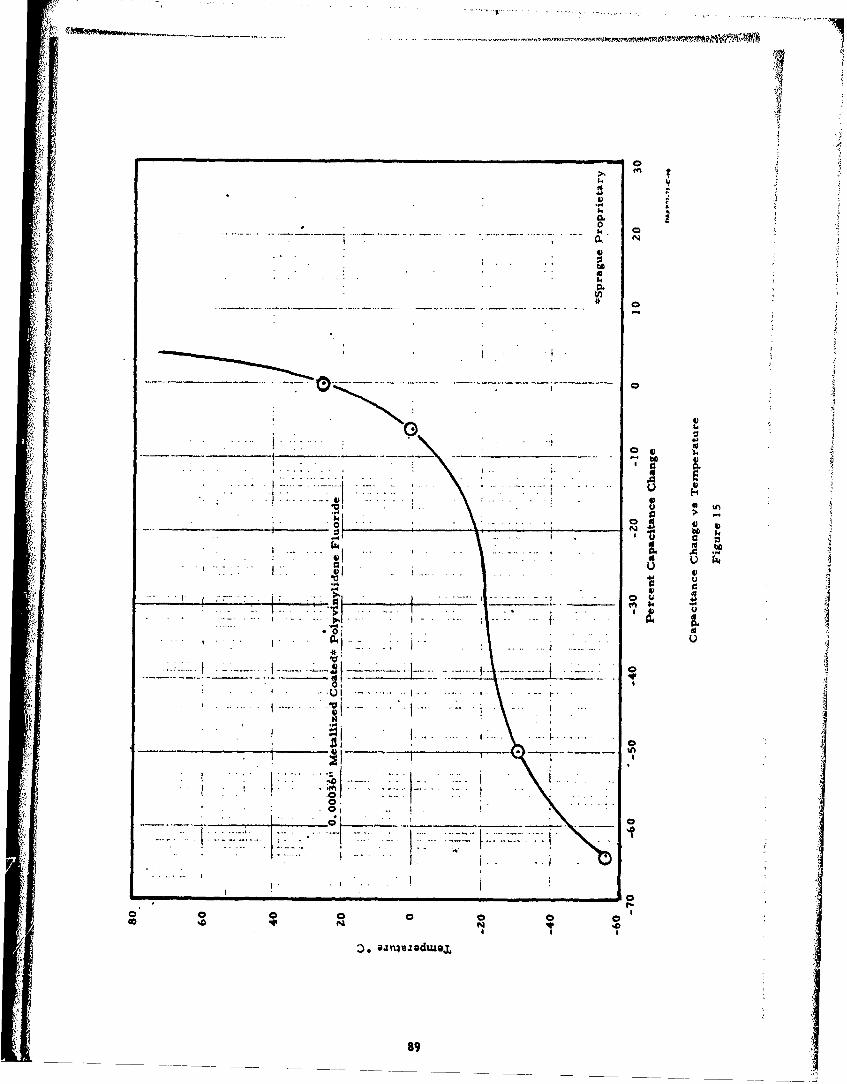
t ..- .. �.-.
2.
Cf� t
I� -
VS..0.0S.. C
� N
S
aS..
.. 0.* C
*1 -
0--" - . I
VS..
..... , M_____ ______ o * a
- .---.- ..---.. _____________ - - S..* ID �- . . .> . .� S1-*j . U
. a--- VI U
S..N 0*- - I -
0.0 ...
- .�-I .... ���1 ___ 0�
". ___ 'f� S.. *-
�t.: II. ,
.1I.----.I---,..-.--
-.-.. C
.�L-..*.I.... --
C
I -.---- U.S
I:: ::�. I I.
I . � .. *i .
f-i-. zzI.-... , .
C
C C C 0 C C C C I0 .0 N N .0a S S
�* �.i�e.zodua.j.
89

TABLE XXXI
CHARGE-DISCHARGE TESTING 30 pps DESIGN E VARIATION 1
(0. 00027' METALLIZED COATED"' PETP, DIFFERENT GEOMETRY,SILICONE OIL IMPREGNATED)
SPRAY PROCESS C, SOLDER PROCESS I
0 Cycles
Unit Capacitance Dissipation Factor Leakage CurrentNo. (•F) M (%)(A)
234 30.94 0.53 0.98235 31.35 0.57 0.20236 32.25 0.87 0.18237 32.36 0.55 0.26238 32.55 0.65 0.53239 31.82 0.77 0.65
10,000, 000 Cycles
234 30.80 0.75 0.88235 31.00 0.64 0.20236 31.32 0.70 0.80237 Shorted 7,860, 553238 31.62 0.85 0.75239 31.60 C.79 0.70
Capacitance and Dissipation Factor at 1000HzLeakage Current at 500VDCTest Voltage 900 VDCTest Temperature 40*CMeasurement Temperature 25*CLoad 32 gH plus I ohm resistorPulse Rate 30 ppsPeak Current z 400 amps. .C.0.41*Sprague Proprietary
90
SEC TION III
CONCLUSIONS AND RECOMMENDATIONS
1. Capacitors weighing approximately six ounces, and capable ofsupplying 12 joules of energy for 50, 000, 000 charge-dischargecycles at 10 pps can be produced using metallized coated,'*,0. 00027" PETP and silicone oil as an impregnant. Thedesign objectives of the contract were accomplished.
2. At a repetition rate of 10 pps, silicone oil impregnated unitsexhibit longer life than do dry unimpregnated units of thesame construction.
3. Silicone oil acts more as a heat transfer medium to conductheat away from the capacitor windings and end connectorsrather than increase the dielectric strength of the unit.
4. By increasing the length of the el',ctrode, the life of a metallizedcoated energy storage capacitor is increased due to the reductionin current per length of electrode.
5. Polysulfone with the present coating system is not a satisfactorydielectric for high repetition rate energy storage capacitors.
6. Coated polycarbonate performed satisfactorily as a dielectricfor energy storage capacitors and it may be superior to coatedPETP at higher repetition rates.
7. Additional work may prove coated Polyvinylidene Fluoride to bea good dielectric at low repetition rates and where loss ofcapacitance at low temperatures is not a critical factor.
8. A coated PETP silicone oil impregnated capacitor will operatesatisfactorily at 30 pps for at least 10, 000, 000 charge-dischargecycle s.
*Metallizing and Coating are Sprague ' Piocesses
91
9. Additional vvrk should be conducted at higher temperatures andrepetitioa rates on metallized coated capacitors.
10. Additional work should be conducted in an effort to measure thedetermining factors of the life of a capacitor.
92