economic and functional feasibility of concrete and steel
TRANSCRIPT

American Journal of Civil Engineering 2021; 9(5): 138-154
http://www.sciencepublishinggroup.com/j/ajce
doi: 10.11648/j.ajce.20210905.11
ISSN: 2330-8729 (Print); ISSN: 2330-8737 (Online)
Economic and Functional Feasibility of Concrete and Steel Composite Column Building Structure
Umair Ahmed1, Assad Rashid
2, *, Zafar Baig
2
1Department of Civil Engineering, Capital University of Science and Technology, Islamabad, Pakistan 2Department of Civil Engineering, University of Management and Technology, Lahore, Pakistan
Email address:
*Corresponding author
To cite this article: Umair Ahmed, Assad Rashid, Zafar Baig. Economic and Functional Feasibility of Concrete and Steel Composite Column Building Structure.
American Journal of Civil Engineering. Vol. 9, No. 5, 2021, pp. 138-154. doi: 10.11648/j.ajce.20210905.11
Received: August 19, 2021; Accepted: September 3, 2021; Published: September 16, 2021
Abstract: Modern day construction is widely influenced using Steel-Concrete composite columns. The rapid growth in
Steel-Concrete composite construction has significantly reduced the use of conventional Reinforced Cement Concrete (R.C.C)
as well as other steel construction practices. Steel-Concrete composite construction gained an extensive receiving around the
globe. Considering the fact that R.C.C construction is most suitable and economic for low-rise construction so it is used in
framing system in most structures. However; increased dead load, span restriction, less stiffness and risky formwork makes
R.C.C construction uneconomical and not suitable when it comes to intermediate to high-rise buildings. One Basement and 11
storeys existing building has been analyzed and comparison has been made between R.CC structure and concrete steel
composite columns. Equivalent Static non -linear analysis was performed in X and Y direction by using Etabs 2017 software
which results that encased composite columns construction cost is more than R.C.C columns but on the other hand encased
composite columns has more floor area, the storey shear is more, story drift is less, storey displacement is less, in conventional
R.C.C structures, storey shear is less in R.C.C conventional structure. Therefore; this research aims to analyze and to learn This
research is an effort to learn cost effectiveness, increased or decreased stiffness and change on functionality of composite
construction for intermediate to high-rise buildings in Pakistan. A Base + Ground +11 storey commercial building was selected
for this study. Comparison is done between conventional R.C.C structure and Encased Composite column structure. Equivalent
Static non-linear analysis was performed using ETABS 2017 software. Although for Base + Ground + 11 storey building the
construction cost is 7.7% more than R.C.C structure but encased composite column building has 13.013% more floor area.
This increased floor area will help to settle the cost difference between two structures.
Keywords: Composite Structures, Concrete Steel Composite Column, Composite Structure Behavior,
Modeling of Composite Columns
1. Introduction
Concrete and Steel Composite Structures are being widely
used around the world. Its use in Pakistan’s construction field
is considerably low, when compared with many developing
countries from around the globe. Concrete and Steel
Composite Structures play a vital role in economic aspects
when constructing high-rise buildings. Reduction in speedy
erection makes steel-concrete composite structures
economically viable. Under seismic conditions, due to
inherent ductility characteristics, steel and concrete
composite frames perform better than conventional
reinforced cement concrete structures. Effect of seismic
forces on composite structures is less due to low dead weight
compared to R.C.C structures.
Lately, with the primer of modern-day composite mount
construction in tall structures, engineers started to develop
strategies to get the stiffening and consolidation effect,
advantages of concrete and steel reinforcement. These factors
directly affect bearing capacity and axial compressibility of
steel and concrete composite column. Using the steel-concrete
composite structural members leads to large openings,
lowering the peak stages and delivers a higher side stiffness.

139 Umair Ahmed et al.: Economic and Functional Feasibility of Concrete and Steel
Composite Column Building Structure
Under earthquake loadings with high magnitudes, concrete
section tends to crack, which results in reduction of the
flexural strength of composite column and beam. The steel
core acts as a back-up system in giving the shear strength and
also the needed plasticity to forestall brittle failure modes.
Campian, Nagy, & Pop, describes experimental
components for steel encased composite steel-concrete
columns. The ultimate flexural stiffness, ductility, and
strength absorption capacity can may be enhanced by
offering the cross ties and reduced spacing of the hoops. This
is attributed often to the expanded confinement furnished
through the way of transverse reinforcement [1]. Chen, Li, &
Weng, have proved by tests that by resisting concrete flexural
and concrete shear cracking that occurs due to increased axial
compression of steel and concrete composite column, joint
behavior improves. Thus, increasing the joint stiffness and
strength. This result is based on the obtained results of many
tests. When load is applied on steel encased concrete
composite column, crushing strength increases by the margin
of 30% as compared to conventional R.C.C column [2].
Nishiyama, Kuramoto & Noguchi, have complemented that
the story number for each building type was chosen different
to find the effect on the cost of these two different types of
construction for medium, high-rise & low buildings [3].
Begum, serajus, Tauhid, & Ahmed, described in their studies
that according to results composite construction is well suited
for high-rise buildings while R.C.C construction works
efficiently in low-rise buildings [4]. Kumawat & Kalurkar
concluded that the price comparison shows that steel-
Concrete composite structure is steeply-priced, direct cost
reduction of the steel concrete composite structure as a result
of rapid construction makes steel-concrete composite
building economically feasible [5].
Construction history plays an important role in the
development of proposed method, as several ideas from other
authors were considered to make it as easy as possible.
Concrete and steel composite structures are widely used
around the world. Its use in construction industry of
Pakistan’s considerably low when compared to many other
developing countries. There is a huge potential for increasing
the volume of composite construction, considering current
development requirements. Three basic types of concrete
composite columns are; sections which are completely
encased, sections which are partially encased and concrete
filled hollow columns. Under seismic conditions, due to
inherent ductility characteristics, steel-concrete composite
structures perform better than conventional reinforced
cement concrete structures. Seismic forces effect it less due
to low dead weight compared to R.C.C structures.
The premature evolution of composite column was due to
its fire-resistant property for structural steel in buildings. By
early 1960, research showed that concrete encasement or
wrapping can increase the load resistance of steel columns.
Economy in construction can be achieved by using better
quality of concrete and introducing the composite section in
design of columns. Both steel section and concrete oppose
the exterior loading by collaborating collectively through
friction and chemical bond. And also, by the use of
mechanical shear connectors in some circumstances.
Although steel concrete composite columns were
infrequently used at the time of World War II till the early
1970s, research had commenced a long time before, at the
start of the 20th
century. To protect the steel columns from
fire they were customarily encased in concrete, while steel
was merged in concrete as reinforcement.
2. Literature Review
Volume of steel in construction can greatly be increased,
especially when we consider current needs of development.
Initially the concept of the composite beam was introduced in a
period 1850-1900 by Emerges. Composite construction includes
a large variety of structural systems, such as; framed structures
using all composite members and mechanisms (composite
beam-columns and joints) and sub-groupings of steel and
reinforced concrete elements. According to Uchida & Tohki, to
increase the resistance and deformation capacity these elements
are used [6]. Steel and concrete composite columns are
comparatively new components which are being used in framed
structures as shown in figure 1. Henceforth, framed systems &
composite columns are discussed from a design, economy,
functionality and technical point of view in detail.
Figure 1. Concrete steel composite columns (encased).
2.1. Design of Composite Structures in Previous Studies
Ellobody & Young, studied the effects of eccentrically
loaded concrete and steel columns (encased). In their study, a
nonlinear 3D finite element model is used to represent these
eccentrically loaded columns. Pin-ended columns were

American Journal of Civil Engineering 2021; 9(5): 138-154 140
subjected to normal load posing along principal trajectory,
with an eccentricity ranging from 0.1250 to 0.3750 of total
depth of sections for understudy columns. considering
model’s limitations, model was responsible for the inelastic
behavior in transverse and longitudinally embedded
reinforcement bars along with concrete confinement of steel
encased concrete composite columns. The functionality
between reinforced concrete sections, transversely and
longitudinally embedded reinforcement bars and concrete
were taken under consideration in order to allow bonding
behavior. Geometrical imperfections had already been
carefully integrated into the model. Nonlinear 3D finite
element model was validated against test results. Variation in
concrete strength was from 30–110 MPa (normal to high).
Stress variation was 275–690 MPa (normal to high). In
addition, a parametric study examined the influencing
variables for composite columns’ strength; column
dimensions, eccentricities, sizes for structural steel, yield
stresses for structural steels and concrete strengths. Because
of the increase in yield stress of structural steel, for oddly
loaded columns with low eccentricity of 0.125D the effect
was significant on composite column’s strength. While, due
to the increment in structural steel’s yield stress with a higher
eccentricity of 0.375D and concrete strength less than 70
MPA the effect on composite column’s strength is
remarkable. The strength which was obtained using finite
element model’s analysis was compared with strengths of
composite columns calculated using Euro-code 4 [7].
Johnson proposed a relative analysis of R.C.C structure and
steel-concrete and composite structure of multistoried building.
Paper explains that reinforced cement concrete structures are
not economically viable due to the increased load and unsafe
framework. Pushover analysis as well as different parameters
like story displacement and story drift were analyzed by using
ETABS 15. It is compiled from different reviews that
composite structure constructions are suitable for high-rise
buildings as compared to R.C.C. structures. Introduction of
concrete composite members in high-rise buildings was our
main objective. Composite columns are compression members,
which are built using different combinations of structural steel
and concrete to use the beneficial properties of each material.
Advantages for concrete composite columns that are explained
in this paper are as follows, for a given cross-sectional
dimension it increases strength, buckling resistance and
stiffness. Resistance to fire and protection against corrosion in
case of an embedded section. Plastic design method is used for
analysis of a thirteen-story reinforced cement concrete and
composite structures. In ETABS 15 non-linear analysis was
adopted for frame analysis. The results and observations show
that overall composite structure is better than R.C.C structures
as composite structures produces less displacement and resist
more structure forces [8].
Wagh & Waghe, did a relative study of steel concrete
composite and R.C.C structures. During this study they did a
comparison of steel concrete composite structures and R.C.C
structures with (G+12, G+16, G+20, G+24) story buildings
situated in zone 2. Dimensions used for plan were 63.20m x
29.50m. Equivalent static method was used for analysis. Both
of these structures were modeled using STAAD pro software
and comparison between results were made. This study
includes; shear force, axial force, deflection produced,
construction cost and bending moment in column. Design
method for this report mainly follows EC4. It can be seen
from results and analysis that reinforced cement concrete
structure is less economical than steel concrete composite
structure when considering high-rise buildings. Cost
difference in this study shows that with increase in number of
stories the cost reduces, when compared to R.C.C buildings.
Also, the construction time consumed by the composite
structure is less. Studies reveal that composite structure
behaves better than R.C.C structure during earthquake.
Results also concluded that smaller size of foundation can be
used in case of composite structures [9].
Panchal & Marathe did a relative study of composite and
R.C.C multistoried buildings. The building considered for
study is a residential structure with G+14 stories situated in
zone 4. The dimensions used for plan of the building are 20m
x 10m, with each story height of 2.3m. The advantages of
composite construction are that; it permits easy structural
repairs, lighter construction, Good fatigue resistance, and
corresponding steel have lower stiffness than the composite
sections. Building is examined using equivalent static method
and response spectrum method. Parameters analyzed for this
building are; deflection, base shear, time period and story
drift. Results show that the composite structure is lighter in
weight than R.C.C structure. Time period of composite is
more than R.C.C. However, displacement for R.C.C is less
than composite structure. Whereas, composite construction is
more economical than the R.C.C structures and consume less
time [10].
Kumawat & Kalurkar, did analysis and design of multi
storied building of composite structures. For this study, a G+9
story building was considered in seismic zone 3. The
provisions used for this is Indian standard: 1893 (Part1)-2002.
Response spectrum analysis and Equivalent Static method
were being used for analysis and modeling of this study, and
software used was SAP2000. From this paper it is settled that
for composite structure the dead weight is 15% to 20% less
than R.C.C building, which results in 15%-20% decrease in
seismic forces. It is also concluded from the results of study
that for composite structures the stiffness rises from almost 6%
to 10% in longitudinal direction and it increases from almost
12% to 15% in transverse direction when compared to R.C.C
structure. In linear static analysis, twisting moment for
composite column is 49% to 65% less in longitudinal direction
and it is 48% to 63% less for transverse direction than R.C.C
columns. In linear static analysis axial force for composite
columns is found to be 20% to 30% less than in case of R.C.C
structures. While, for linear dynamic analysis axial force in
composite columns is found to be 18% to 30% less than R.C.C
structures. So, it can be said that structurally, composite
structure performs better than R.C.C structure [5].
In (Committee & Standardization, 2008) ACI 318-14
(10.3.1.6) it is given that steel thickness encasement is to be

141 Umair Ahmed et al.: Economic and Functional Feasibility of Concrete and Steel
Composite Column Building Structure
taken (a) or (b) for concrete core encased by structural steel
for composite columns [11].
�� ����� for each face of width b ACI318-14 10.3.1.6
ℎ� ���� for circular sections of diameter h
Steel-encased concrete sections should have a steel wall
thickness large enough to attain the longitudinal yield stress
before buckling outward.
However, the literature disagrees with the precise value of
maximum unlimited compressive stress, particularly when
higher-strength concrete is used. Conditions like AISC-
LRFD (AISC 2001) and ACI-318 (Committee, 2002)
recommend 0.85 fc'. [12]
Young & Ellobody, introduced a strength reduction factor
of 0.92 for high strength concrete in a range of [75-90 MPa
(11 - 13 Ksi) [7]. Martinez et al. proved in their research that
a ratio of 0.85 for unconfined column strength to cylindrical
strength for concrete strength ranging from [25–70 MPa
(3.5–10 ksi)]. His given value is irrespective of concrete
strength. Cusson & Paultre, performed many tests on
concrete strength ranging from 59–117 MPa (8.5–17 Ksi) and
found the average value of 0.88 for fc' [13]. While, Collins,
Mitchell, & MacGregor, after extensive research and test
performances gave a value of fc' ranging from 0.77 fc
' to 1.0
fc' for maximum compression stress value. From above given
values of fc' a conclusion can be made that there is an
agreement on lower part of stress strain curve [14].
Ahmad & Shah, concluded in their study that high strength
concrete of 69 MPa (10 Ksi) can be ductile same as low to
intermediate strength concrete. However, these trends cannot
be found for concrete strength ranging from 76-90 MPa (11-
13 Ksi) in tests performed by Young & Ellobody in 2011
[15]. Martinez et al. gives conclusion for concrete strength
from 48-68 MPa (7-10 Ksi) that the stress- strain curve goes
down instantly after it achieves highest value. After this it
goes flat showing high axial compressive stress. Mirza &
Skrabek, in their study showed that from yielding of
transverse reinforcement such as hoops, column flanges and
in case of steel encased columns, steel tube can be used to
find the confined compressive strength. We can take that the
confining pressure that is generated after loading can be
assumed as active pressure and will remain there always as
said by Hajjar & Gourley. The results which are extracted
from the tests performed are quite promising for steel
encased concrete filled columns and for concrete encased
steel section composite columns [16, 17].
El-Tawil & Deierlein, describes the requirements of ACI
318 and concluded that these provisions are same as for
reinforced concrete for calculation of strength interaction
between axial and flexural effects. The whole provisions are
based on a simple assumption of linear strain distribution
over the steel concrete composite column cross section
giving maximum value at outermost point in figure. For
finding the nominal strength of concrete block the tensile
strength is not considered and a stress block with value for
stress ordinate of 0.85 is taken and then it is related to
nominal strength. For calculation of induced stresses in both
reinforcing and structural steel, the values of elastic modulus
and strain is taken to the limiting point of nominal yield
strength [18]. In this case stress hardening is not taken into
consideration. The compressive strength for encased column
is limited to a value of 0.8P0.
Where
P0= (0.85f'Ac+ FyrAr + FysAs)
In the above equation Ac, Ar and As stand for the concrete
area, structural steel area and reinforcing steel area
respectively. Due deflection in columns, the slenderness
effect will take place through moment modification.
The ACI-318 and AISC-LFRD gives conclusions; (1) it
concludes that ACI-318 is better than AISC-LFRD in
modelling the overall behavior of composite structure. The
accuracy of modelling depends upon slenderness ratios along
with steel and concrete strength ratios. (2) When compared
with both short and long column ACI-318 gives some un-
conservative results (As up to 8-10%). (3) The conservative
value for short columns in both codes ACI- 318 and AISC-
LFRD is 40%. The value for long column is with steel ratios
of (L/r = 40 and As/Ag = 16%). The outer fiber strength and
AISC-LFRD does have much of difference. The strength
reduction is very less i.e. 6% resulting from the sequence of
construction for columns having value less than L/r<<40.
Figure 2. Composite section analysis.
The method for analysis and specification is developed
using a limited number of data. But this limited number of
data can produce some feasible results to check for the
differences in existing design. As a result of this research,
amore methods for computer analysis can be used such as
fiber integration technique. Models and computer
programs can be developed using this method to design
the reinforced and composite structures using nonlinear
analysis method. Some of such programs can greatly
improve the practical importance of this method in the

American Journal of Civil Engineering 2021; 9(5): 138-154 142
context of response of structural system.
2.2. Economic Comparison of R.C.C and Steel-Concrete
Composite Column Structures
Boke & Suryawanshi, made a qualified study of composite
structure (G+10) and Reinforced concrete residential
building. Objective of the analysis was to review the
behavior of R.C.C and composite structures underneath the
impact of seismic loading. Response spectrum analysis was
used for G+10 storied structures. Base shear, displacement
and inter-story drift were core considerations for this study.
For composite structure, base shear was determined to be
34% and for steel concrete structure it was determined to be
26% as compared to R.C.C structure. Dislocation of
composite concrete structure was 49% enhanced and 46%
was enhanced for steel concrete structure when compared
with R.C.C structure. Forces in column for steel structure
were reduced 44% and that in composite steel structure, were
reduced 54% when compared with R.C.C building. Due to
the reduction of column forces the footing sizes also decrease
in comparison to the footing size of reinforced concrete
building. This concludes that structure of composite steel
concrete is cheaper than the reinforced concrete structures.
As there is no form work required in composite structures,
this reduces construction time when compared with
Reinforced concrete buildings [19].
Liang, did a comparative study of cost of reinforced
concrete and steel concrete composite structure. They
compared reinforced concrete structure with composite
structure having different stories like G+9, G+12, G+15, and
G+ 18 having a height of 3m of every floor, located at Pune
seismic zone 3. As far as analysis is concerned Equivalent
Static Method was used. STAAD-PRO software was used for
the comparison of results. Stiffness, drift, displacement, axial
and shear forces in column, bending and twisting moments in
column of stories of composite structures will be compared
with R.C.C structures. 15m x 9m is the complete building
dimension. STAAD-PRO 2007 is used for the analysis and
load calculation for study and design. Study of load
combination has been done as per Indian standard code of
practice. Economic results which were found from this
research are shown in Table 1 [20].
Table 1. Economic Comparison.
Story Cost of R.C.C Structure Cost of composite Structure Difference %
G+9 6007325 3418120 43.1%
G+12 7730830 4042635 47.3%
G+15 9695255 4970475 48.7%
G+18 10876325 4591360 57.8%
Cost evaluation reveals that composite structure is
economical, decreases the direct cost of composite structure.
The performance of the composite structure will be better
than the reinforced concrete structure under seismic
conditions due to its inherent ductility characteristics. In
reinforced concrete structure bending moment, deflections
and axial forces remain slightly additional to that in the steel
concrete composite structures. Forces produced due to
earthquake does not cause destruction to the composite steel
concrete structure when compared with reinforced concrete
structures. Due to less dead weight of steel, composite
building weighs less when compared to reinforced concrete
building reliefs in falling the cost of foundation.
Ambe & Maru, did a relative study on the steel concrete
composite structures and reinforced concrete structure. They
compared a G+15 story office building for both steel
concrete composite building and reinforced concrete building
located in earthquake zone 4 with wind speed 39 m/s.
Analysis Method used was equivalent static method.
STAAD-PRO was used for the steel composite structure and
reinforced concrete structure. modeling and their results were
compared. Results show that steel concrete composite
structures are economical than R.C.C. structures. The cost
comparison in this paper showed that composite steel
structures are economical than reinforced concrete structures.
More it concludes that composite construction is fast. A
structure, if constructed using R.C.C construction approach
can take up to 24 months of time to finish. While, if same
structure was constructed using composite construction
approach it can save almost 9 months of time [21].
Shashikala & Itti, did a comparative study of R.C.C and
composite multi-storied buildings. In their study the building
that is chosen is located in earthquake zone, residential
building (B+G+15). earthquake loading, requirements of
Indian standard: 1893 (Part 1 2002) is used. Software used
was STAAD Pro V8i for the modeling of the composite
structure and reinforced concrete building. Composite
structure and R.C.C structure are analyzed by STAAD pro
using equivalent static method. The work determined that the
composite column cost less than R.C.C columns by 20.45%
shown in table 2 and table 3. [22].
Table 2. Cost of R.C.C Columns for Composite Structure.
Material Quantity of R.C.C column for Composite Structure Rate Amount in Rs
Steel 107.87 ton 51500M/T 5606805
Concrete 475.75 m3 6000 2254500
Total Cost of R.C.C Column for Composite Structure 7861305

143 Umair Ahmed et al.: Economic and Functional Feasibility of Concrete and Steel
Composite Column Building Structure
Table 3. Cost of R.C.C Columns for R.C.C Structure.
Material Quantity of R.C.C column for R.C.C Structure Rate Amount in Rs
Steel 145.94 (ton) 51500M/T 7515910
Concrete 394.53 m3 6000 2367180
Total Cost of R.C.C Column for R.C.C Structure 9883090
Tedia & Maru, did a relative study of cost, analysis and
design of composite concrete structures and R.C.C structures.
The building thought-about for the study is G+5 story
building with height of each story is 3.658m and arrange
dimensions of 56.3m x 31.94m. Building is located in zone
three. Modeling of R.C.C and steel concrete composite
structure is finished on STAAD-PRO code and therefore the
technique used is Equivalent static technique. This study
reveals that composite structure for G+5 is costlier than that
of R.C.C structures [23].
2.3. Modeling of Steel-Concrete Column Structure
Bridge, presented the design for steel concrete composite
structures. material design approaches of AS3600, AS4100 and
Euro code 4 (EC4) are compared in this paper. Comparison is
done to discuss the differences and to point out the likenesses.
Simple plastic method or strain compatibility method is used for
the determination of the cross-section. Using moment
magnification of first order or direct analysis, all of this needs to
determine the second order effects. Difference between these
approaches is the method in which geometric and material
imperfections along with stability is considered. In euro code 4,
the approach for composite column is similar to R.C.C columns.
Effects of second order imperfections are to be taken explicitly for
members. By using euro code 4, for the expression of Cm, the
value for a column is 1.1 through identical end moment’s
determination in equal arc. This shows end moments causing 10%
imperfections. In the analysis of second order the effective
stiffness used, is elastic stiffness which is modified by calibration
factor and correction [24].
In Eurocode 4 (CEN, 1994) for the design of column
(composite) with symmetrical cross section a general method
is specified. Plane sections are assumed for the calculation of
the flexural strength. In United States the ACI codes for
building uses the same design philosophy. That’s why for the
prediction of the strengths of the specimens ACI provisions
are used. In ACI and AISC-LRFD the requirements used for
composite-column design is principally based on provisions
to design for structural steel column and reinforced concrete
column respectively. Method adopted by AISC-LRFD is a
bilinear communication curvature among flexural strength
and axial compression through following equation and
modeling steps are shown in figure 3 and figure 4 [25].
For
Pu ��� ≥ 0.2
Pu ��� +
89 (
Mux ���� +
Muy ����) ≤ 1.0
2.4. Beam-Column Joints
Liang described in his studies that the column beam
connection zone is one of the most important areas in earthquake
resistance structure design principles. By increasing the
construction of the high-rise buildings, big span bridges, heavy
load industrial structures, indoor stadiums and deep piers, the
usages of the concrete encased composite and concrete filled
steel tubular columns have been extensive recently. Due to
sufficient structural behaviors such as high strength, good
stiffness, great ductility and large strain energy absorption
capacity concrete encased composite columns are preferred in
modern structures especially in high seismic zone areas. [20]
The failure criteria of any element can be projected
according to the location of the plastic hinge. In this study,
plastic hinge had two expected locations; first one is before
the transfer part in the reinforced concrete beam and second
one is located at the joint where the beam section is a
composite one, see Figure 5.
Figure 3. Modelling Steps-II.
Figure 4. Modelling Steps-I.

American Journal of Civil Engineering 2021; 9(5): 138-154 144
Figure 5. Model Static System.
3. Methodology
3.1. Selection of Building
A R.C.C commercial structure selected for the study, is
located in Islamabad. Islamabad exists in seismic zone 2B
(Building Code of Pakistan 2007). The dimensions of the
commercial building are 160 ft. x 78 ft. Building comprises
of one basement of 10 ft in height which will be used for car
parking. The ground floor, first floor and second floor are
used for commercial purposes such as mall and shops having
height of 14 ft. each. The remaining floors from third to tenth
story have height of 12 ft. The third, fourth and fifth floor
will be used for offices. The stories from sixth to tenth will
be reserved for residential purposes. The total height of
building including basement and mumty is 170 ft.
3.2. Architecture Drawings and Modeling
Drawings for building are produced using AutoCAD 2009
shown in figure 6. Plans are drawn along with side and front
elevations. The building has been modeled in ETABS 2017
in seismic zone 2B using soil profile SD UBC (Code 1997) as
bare frame structure as per design provision of building code
of Pakistan, ACI-318, UBC-97, Euro code 4 and AISC-
LFRD. [26, 27]
Figure 6. Basement Plan of Building.
3.3. Modelling and Analysis Specifications
The parameters used to demonstrate the procedure for
computer-aided seismic analysis and design of basement,
ground and eleven-story building which is a frame structure,
located in seismic zone 2B and soil type SD are given below.
FPS System is used for the project. Modelling and analysis
has been done using ETABS 2017.
3.3.1. Concrete Compressive Strengths
The concrete compressive strength used for design is
R.C.C Columns: 4000 psi
R.C.C Beams: 3000 psi
Slabs: 3000 psi
Lean Concrete 800 psi
3.3.2. Dead Loads
Dead loads of structure are calculated from respective
sizes of structural members and densities of materials used.
Material used in structure and their load per square foot is
given below:
Reinforced Cement Concrete (R.C.C): 150 "�/$%&
Plain Cement Concrete (P.C.C): 144 "�/$%&
Brick Masonry: 120 "�/$%&
Soil: 110 "�/$%&
Structural Steel: 490"�/$%& 3.3.3. Superimposed Dead
Superimposed dead loads of structure are calculated

145 Umair Ahmed et al.: Economic and Functional Feasibility of Concrete and Steel
Composite Column Building Structure
from respective sizes of structural members and densities
of materials used. It includes dead loads from floor
finishes and partition walls, exterior walls of brick
masonry.
Floor Finishes: 35 "�/$%&
Exterior walls: 25 "�/$%&
3.3.4. Live Loads
Live Loads are applied as per Table 4 of Design of
Concrete Structures, (Page # 11, Arthur H. Nilson; 14th
edition).
Roof Live Load: 20 "�/$%&
Assembly Area: 100"�/$%& Table 4. Minimum Uniformly Distributed Loads.
Occupancy or Use Live Load, psfa Occupancy or Use Live Load, psfa
Offices 50 Schools
Corridors above the first floor 80 Classrooms 40
Penal institutions
Corridors above first floor 80
Cell blocks 40 First-floor corridors 100
Corridors 100 Sidewalks, vehicular driveways, and yards subject to
truckinge 250
Residential
Stadiums and arenas
Dwellings (one and two- family)
Bleachersc 100
Uninhabitable attics without storage 10 Fixed seats (fastened to floor)c 60
Uninhabitable attics with storage 20 Stairs and exit ways 100
Habitable attics and sleeping area 30 One and two-family residence only 40
All other areas except stairs and balconies 40 Storage areas above ceilings 20
Hotels and multifamily houses
Storage warehouses (shall be designed for heavier
loads if required for anticipated storage)
Private rooms and corridors serving them 40 Light 125
Public rooms and corridors serving them 100 Heavy 250
Reviewing stands, grand stands, and bleachersc Roofs
Stores
Ordinary flat, pitched, and curved roofs 20 Retails
Roofs used for promenade purposes 60 First floor 100
Roofs used for roof gardens or assembly purpose 100 Upper floors 73
Roofs used for other special purposesf
Wholesale, all floors 125
Awnings and canopies
Walkways and elevated platforms 60
Fabric construction supported by a lightweight rigid
skeleton structureg 5 (other than exitways)
Yards and terraces, pedestrians 100
All other construction 20
3.3.5. Earthquake Loads
Earthquake Loads are applied as Building Code of
Pakistan Seismic Provisions 2007 and UBC-97.
The following parameters are used in design.
Seismic Zone: 2B (Ref. BCOP 2007)
Site Class (Geotechnical): SD (Geotechnical Report)
Response Modification Coefficient (R): 8.5
Importance Factor (I): 1
3.3.6. Load Combinations
Orthogonal effects have been applied in load combinations
by considering 100% EQ in one direction and 30% EQ in
perpendicular direction as per clause of UBC-97. (UBC-97
1633.1 General).
3.4. Equivalent Static Analysis
Design analysis has been performed using ACI 318 and
Eurocode 4 provisions for R.C.C and Composite columns.
Finite element model prepared in ETABS 2017.
Economic comparison will be done by preparing bill of
quantities (BOQ) using present material construction cost.
These will then be presented in the form of table.
The equivalent static method is a simplified lateral force
procedure to inculcate the seismic (dynamic) loading in
design process. It uses static force procedure to distribute the
effect of lateral load V in two main axis i.e. X-axis and Y-
axis direction. It includes following steps:
1) First step is to calculate the lateral force V acting on
structure. The lateral force depends upon the soil type,
importance factor of building, fundamental and
natural time period of building, design ground
acceleration (depends upon seismic zone), system that
is resisting lateral force and the overall weight of
structure including dead some or full live load.
2) The vertical seismic force distribution is determined
along the height of structure. The height and force
magnitude are proportional to each other.
3) Considering that the diaphragm is rigid, the overall
distribution of forces on each level horizontal and
resisting vertical elements.
4) Calculation of the additional forces from the inherent and
accidental torsion to be added to the forces resulting from
the horizontal distribution of the level forces.
5) Determination of the drift, overturning moment, and
P-Delta effect that are the direct results of the action
of the lateral seismic forces.
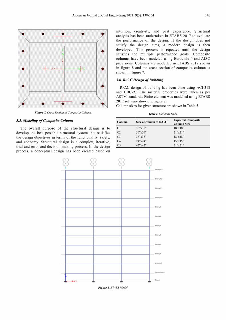
American Journal of Civil Engineering 2021; 9(5): 138-154 146
Figure 7. Cross Section of Composite Column.
3.5. Modeling of Composite Column
The overall purpose of the structural design is to
develop the best possible structural system that satisfies
the design objectives in terms of the functionality, safety,
and economy. Structural design is a complex, iterative,
trial-and-error and decision-making process. In the design
process, a conceptual design has been created based on
intuition, creativity, and past experience. Structural
analysis has been undertaken in ETABS 2017 to evaluate
the performance of the design. If the design does not
satisfy the design aims, a modern design is then
developed. This process is repeated until the design
satisfies the multiple performance goals. Composite
columns have been modeled using Eurocode 4 and AISC
provisions. Columns are modelled in ETABS 2017 shown
in figure 8 and the cross section of composite column is
shown in figure 7.
3.6. R.C.C Design of Building
R.C.C design of building has been done using ACI-318
and UBC-97. The material properties were taken as per
ASTM standards. Finite element was modelled using ETABS
2017 software shown in figure 8.
Column sizes for given structure are shown in Table 5.
Table 5. Columns Sizes.
Column Size of column of R.C.C Expected Composite
Column Size
C1 30”x30” 18”x18”
C2 36”x36” 21”x21”
C3 36”x36” 18”x18”
C4 24”x24” 15”x15”
C5 42”x42” 21”x21”
Figure 8. ETABS Model.

147 Umair Ahmed et al.: Economic and Functional Feasibility of Concrete and Steel
Composite Column Building Structure
3.7. Result Comparison
The behavior of Composite column and R.C.C structure
has been compared. The result comparison has been done for
the following.
3.7.1. Structure Displacement
Structural displacement has been checked by using results
from ETABS model of both R.C.C and steel concrete
composite column.
3.7.2. Story Drift
Change in story drift of a normal R.C.C structure and steel
concrete composite column structure has been compared
from ETABS model:
3.7.3. Base Shear
Base shear has been compared in the form of table for both
R.C.C and composite column structure.
Similarly following has also been compared.
Yield Strength.
Economic Comparison.
Effect on functionality of Building.
3.8. Beam Column Connection
Concret beam and column joints are modelled as shown in
figure 9.
Figure 9. Proposed Connection Technique.
All beams are connected to the column in the same way;
the steel beam is welded to an end plate which is connected
to the column by using bolts. The beam is considered a
transfer part; the remaining part is reinforced concrete one
with top and bottom reinforcement. It is important to state
that the reinforcement covers the whole span of the beam
including the transfer part. All beam and columns have the
same connection details which are shown in figure 10.
Figure 10. Elevation and Cross Section.
Figure 11. Column Cross-section and Foundation Detail.

American Journal of Civil Engineering 2021; 9(5): 138-154 148
3.9. Foundation Connection of Composite Column
The proposed way to connect the column to the foundation
is shown in figure 11(a) and figure 11(b). This method is
used around the world to connect steel column to
foundations. The size of base plate and foundation is
dependent of load acting at foundation.
4. Result and Discussion
Equivalent static analysis was performed on R.C.C and
Composite Column building in ETABS. A R.C.C commercial
structure, selected for the study, is located in Islamabad.
Islamabad exists in seismic zone 2B (Building Code of
Pakistan 2007). The dimensions of the commercial building
are 157.5 ft. x 78 ft. Building comprises of one basement of
12 ft in height which will be used for car parking. The ground
floor, first floor and second floor are used for commercial
purposes such as mall and shops having height of 12 ft. each.
The remaining floors from third to tenth story have height of
12 ft. The third, fourth and fifth floor will be used for offices.
The stories from sixth to tenth has been reserved for
residential purposes. The total height of building including
basement and mumty is 160 ft. The results are of base shear;
displacement, ground over-turning moment, storey drift,
storey shear, ductility, mode shape, model period, quantities
and floor area ratio which are compared between R.C.C
structure and Composite column structure.
4.1. Results for Zone 2B (X & Y Direction)
The results are shown in figure 12 and figure 13.
According to the building code of Pakistan, 2007, the peak
ground acceleration is 0.2g against which the building has
been designed. Results in X and Y-direction between
comparison of R.C.C structure and Concrete Encased
Composite Column structure include; base shear,
displacement, ground over-turning moment; storey drift,
storey shear, ductility, mode shape, model period, quantities,
cost comparison, floor area ratio and column sizes.
Figure 12. Lateral Force Comparison (X-Direction).
Figure 13. Lateral Force Comparison (Y-Direction).

149 Umair Ahmed et al.: Economic and Functional Feasibility of Concrete and Steel
Composite Column Building Structure
4.1.1. Lateral Force Comparison
In Figure 12, lateral force versus storey level is plotted for
both R.C.C and Encased Composite Column for X and Y
direction, the values gradually increase as storey level
increases. The graph shows that lateral force for R.C.C is
greater than as compared to Composite structure. The
difference between frames with encased composite column
and R.C.C is 7.943%. Storey lateral forces decreases in
encased column structure.
4.1.2. Storey Shear Comparison
Figure 14. Storey Shear EY.
Figure 15. Storey Shear EX.
In figure 14 and figure 15, Shear Force and storey level is
plotted for both R.C.C and Encased Composite Column for X
and Y direction, the values gradually decrease as storey level
increases. The graph shows that shear force for R.C.C is
greater than as compared to Composite structure. The
difference between frames with encased composite column
and R.C.C is 5.67%. There is less shear acting on Encased
composite column than R.C.C and the reason is due to
overall less dead weight acting on structure.
Figure 16. Storey Drift Comparison EX.
4.1.3. Storey Drift Comparison
Storey drift gradually increases at first from base to ground
storey. As the no. of storey increases, somewhere around fifth
story the storey drift of both frame reaches their maximum
values with Encased Composite having larger storey drift
value than that RCC structure. Storey drift for both structures
gradually decreases as it moves along the top storey. The
trend of graphs in Figures 16 and 17 respectively shows that
the storey drift for encased composite column structure is
more as compared to R.C.C structure. This is due to small
sizes of columns in Encased Composite column structure
when compared to R.C.C (see Table 6). The storey drift in
EY direction is more as Figure 16 shows, this is because of
building orientation i.e., in EY direction building spans only
78 ft as compared to EX where it spans for 157.5 ft.
Figure 17. Storey Drift Comparison EY.

American Journal of Civil Engineering 2021; 9(5): 138-154 150
Figure 18. Story Displacement (EX-Direction).
Figure 19. Story Displacement (EY-Direction).
4.1.4. Storey Displacement Comparison
Above figures shows the graphs of displacement versus
storey level. The graph in X-direction is discussed first. In
Figure 18, encased composite column shows more
displacement than R.C.C Structure and the difference is
7.73%. Composite column structure displays more
displacement and less base shear.
Now in figure 19, graph shows displacement Y-direction.
In Figure 19, encased composite column shows more
displacement than R.C.C Structure and the difference is
10.17%. Composite column structure displays more
displacement and less base shear in both directions.
More displacement is due to small sizes of columns in
encased composite column structure so this result in less
dead weight of structure which alternately result in less base
shear.

151 Umair Ahmed et al.: Economic and Functional Feasibility of Concrete and Steel
Composite Column Building Structure
4.1.5. Overturning Moment Comparison
In figure 20, the graphs of over-turning moment against
storey level. The trend in graph gradually decreases from
maximum at base as the storey level increases. As figure
illustrate that the encased composite column structure has
less overturning moment as compared to R.C.C structure and
percentage difference is 5.5%.
Figure 20. Overturning Moment.
4.1.6. Mode Period and Frequency Comparison
Figure 21. Time Period Comparison.
Figure 22. Frequency Comparison.
In figure 21, the graph of mode and time period of both
R.C.C and composite column structure. The maximum value
of time period for R.C.C structure is 2.579 sec and for
encased composite column structure it is 2.776 sec. The time
period of R.C.C structure is less as compared to encased
composite column structure which means the time period
R.C.C will be greater than composite column structure. The
percentage difference is 7.096%
In figure 22, the frequency of composite column structure
is less than R.C.C structure and the difference is 20.255%.
4.1.7. Moment Curvature/ Ductility
1) Columns Comparison
Figure 23. Moment Curvature Comparison.
R.C.C and composite columns are compared and the
R.C.C column has a size of 54x54 inches whereas encased
composite column has a size of 42x42 inches. In figure 23
the moment capacity of Encased composite column is 39%
more than R.C.C column of greater cross-section. This shows
that encased composite column can resist more moment than
R.C.C and thus will perform better in case of earthquake.
Similarly figure 24 columns are compared. The size of
composite column is 33x33 inches while the R.C.C column
size is 44x44 inches. The moment capacity of encased
composite column is 20.9% more than R.C.C column.

American Journal of Civil Engineering 2021; 9(5): 138-154 152
Figure 24. Moment Curvature Comparison.
2) Column Sizes Comparison
Table 6. Column Size Comparison.
Column Size of column of R.C.C Composite Column Size
IC 54”x54” 36”x36”
OC 45”x45” 33”x33”
OC 42”x42” 30”x30”
*IC inner column *OC outer column.
It can be seen in table 6, that the column sizes in encased
composite section are reduced by 1.5 ft. This means that the
composite column structure the span beam is increased by 3
ft saving valuable space to be utilized for commercial
purposes.
4.2. Quantities and Cost Comparison
4.2.1. R.C.C Structure
The total steel requires for the construction of super structure
i.e., from base to mumty is 558.979 tons. The total concrete
require for construction of super structure is 209437 cft.
4.2.2. Encased Composite Column Structure
The total steel required for the construction of super structure
i.e., from base to mumty is 747.6616 tons. The total concrete
require for construction of super structure is 198701 cft.
4.2.3. Floor Area Ratios
Floor area for R.C.C structure is 147182.22 ft2 and for
encased composite Column structure it is 159452.5 ft2. The
floor area for composite column structure is 12270.25 ft2
more than R.C.C structure that is 7.7%.
4.2.4. Cost Comparison
Table 7. Cost Comparison.
Structure Steel tons Steel Cost Rs Concrete cft Concrete Cost Rs Total Cost Millions
R.C.C 558.9495 58689695.1 209437.7 41510000 100.20
Composite 748.6616 78609464.2 198701.5 36582000 115.19
5. Conclusion
A B+G+11 storey commercial building was selected for
the study. The comparison is done between conventional
R.C.C structure and Encased Composite column structure.
Equivalent Static non-linear analysis was performed using
ETABS 2017 software. The results were extracted in X and Y
direction. In X-direction and Y-direction, base shear,
displacement, ground over-turning moment, storey drift,
storey shear, lateral forces, floor area, column sizes and cost
is compared between conventional R.C.C structure and
Encased Composite column structure. The important
conclusions of this study are elaborated as under:
i. The storey shear for conventional R.C.C structure is
more than encased composite column structure. This
is due to the more dead weight of R.C.C building.
ii. Storey drift for the R.C.C is less than encased
composite column structure in both X and Y
direction.
iii. Storey displacement for R.C.C structure is less as
compared to encased composite column structure.
This is due to the small sizes of columns in encased
composite column structure.
iv. The overturning moment of R.C.C structure is 5.5%
more than encased composite column structure.
v. The modal time period of Encased composite
column structure is more than R.C.C structure and
this due less stiffness of encased composite column
structure.
vi. Moment capacity of encased composite column of
36x36 inches is 39% more than a 54x54 inches
R.C.C column. This shows that encased composite
column can sustain more load for smaller cross-
sections.
vii. Inner columns are reduced by 18 inches for encased
section. This means that a lot of valuable space can
be saved in structure.
viii. The floor area for encased composite column
structure is increased by 7.7%, i.e. 12170.55 ft2.
ix. The cost of R.C.C structure is less than encased
composite column by 13.01%. This cost can be
overcome by floor area increased in encased
composite column structure.
6. Recommendation
As stated in the above-mentioned results, there are
differences in seismic response of frames for R.C.C and
encased composite column. Building analysis and design
shows that encased composite column structure has less
weight and is less stiff than R.C.C structure thus it has more
modal time period and less frequency. The axial compression
and moment carrying capacity of encased composite
structure is also more than conventional R.C.C structure.
From the results we can easily conclude that in performance

153 Umair Ahmed et al.: Economic and Functional Feasibility of Concrete and Steel
Composite Column Building Structure
encased composite column is superior then a conventional
R.C.C structure. Although for B+G+11 storey building the
construction cost is more than R.C.C structure but encased
composite column building has more floor area. This
increased floor area will help to settle the cost difference
between two structures. For better performance and cost
control it is recommended that encased composite column
should be used in construction of medium to high rise
buildings where cost will be less than R.C.C structure.
List of Abbreviations and Symbols
Ac, Ar: area of concrete and longitudinal reinforcement,
respectively
As, Aw: area of steel shape and web of steel shape,
respectively
B1: moment magnifier suggested in AISC-LRFD
specification
Ec: elastic modulus of concrete
Em:: modified modulus of elasticity
Fcr: critical stress of column
Fmy: modified yield stress
Fy: specified yield strength of steel shape
Fyr: specified yield strength of longitudinal reinforcement
fc':: specified compressive strength of concrete
h1: width of composite cross section perpendicular to the
plane of bending
h2: width of composite cross section parallel to the plane
of bending
Ig: gross section moment of inertia
KL: effective length
Mn: nominal moment capacity without axial load
Mu: factored moment
Mu1, Mu2: the smaller and the larger required moments
applied at both ends of the column, respectively
P0: composite column capacity under uniaxial compression
Pc: critical load of column
Pn: nominal axial compressive capacity
Pu:: factored axial load
r: radius of gyration
rm: modified radius of gyration
Z: plastic section modulus of steel shape
δ:: moment magnifier suggested in ACI-318 code
φb: resistance factor for bending, taken as 0.9
φc: resistance factor for compression, taken as 0.85
λc: slenderness parameter
References
[1] Campian, C., Nagy, Z., & Pop, M. (2015). Behavior of fully encased steel-concrete composite columns subjected to monotonic and cyclic loading. Procedia engineering, 117, 439-451.
[2] Chen, C.-C., Li, J.-M., & Weng, C.-C. (2005). Experimental behaviour and strength of concrete-encased composite beam–columns with T-shaped steel section under cyclic loading. Journal of constructional steel research, 61 (7), 863-881.
[3] Deierlein, G. G., & Noguchi, H. (2004). Overview of US–Japan research on the seismic design of composite reinforced concrete and steel moment frame structures. Journal of Structural engineering, 130 (2), 361-367.
[4] Begum, M., SERAJUS, S. M., TAUHID, B. K. N., & Ahmed, W. (2013). Cost analysis of steel concrete composite structures in Bangladesh.
[5] Kumawat, M. S., & Kalurkar, L. (2014). Cost Analysis of Steel-Concrete Composite Structure. International Journal of structural and Civil Engineering Research) ISSN, 158-167.
[6] Uchida, N., & Tohki, H. (1997). Design of high-rise building using round tubular steel composite columns. Paper presented at the Composite construction-conventional and innovative. International conference.
[7] Ellobody, E., & Young, B. (2011). Numerical simulation of concrete encased steel composite columns. Journal of constructional steel research, 67 (2), 211-222.
[8] Johnson, R. P. (2018). Composite Structures of Steel and Concrete: beams, slabs, columns and frames for buildings: John Wiley & Sons.
[9] Wagh, S. A., & Waghe, U. (2014). Comparative Study of RCC and Steel Concrete Composite Structures. Journal of Engineering Research and Applications, ISSN, 2248-9622.
[10] Panchal, D., & Marathe, P. (2011). Comparative Study of RCC, steel and composite (G+ 30 storey) building. Nirma University, Ahmedabad, India.
[11] Committee, A., & Standardization, I. O. f. (2008). Building code requirements for structural concrete (ACI 318-08) and commentary.
[12] Committee, A. (2002). Building code requirements for structural concrete: (ACI 318-02) and commentary (ACI 318R-02).
[13] Cusson, D., & Paultre, P. (1994). High-strength concrete columns confined by rectangular ties. Journal of Structural engineering, 120 (3), 783-804.
[14] Collins, M. P., Mitchell, D., & MacGregor, J. G. (1993). Structural design considerations for high-strength concrete. Concrete international, 15 (5), 27-34.
[15] Ahmad, S., & Shah, S. P. (1982). Stress-strain curves of concrete confined by spiral reinforcement. Paper presented at the Journal Proceedings.
[16] Mirza, S. A., & Skrabek, B. (1992). Statistical analysis of slender composite beam-column strength. Journal of Structural engineering, 118 (5), 1312-1332.
[17] Hajjar, J. F., & Gourley, B. C. (1996). Representation of concrete-filled steel tube cross-section strength. Journal of Structural engineering, 122 (11), 1327-1336.
[18] El-Tawil, S., & Deierlein, G. G. (1999). Strength and ductility of concrete encased composite columns. Journal of Structural engineering, 125 (9), 1009-1019.
[19] Agrawal, A., Sharma, A., & Pandey, M. Review Paper on Seismic Analysis of RCC and Steel Composite Building.
[20] Liang, Q. Q. (2014). Analysis and design of steel and composite structures: CRC Press.

American Journal of Civil Engineering 2021; 9(5): 138-154 154
[21] Ambe, V., & Maru, S. Life Cycle Cost Assessment of Multistory Steel Concrete Composite Building.
[22] Shashikala, K., & Itti, S. (2013). Comparative Study of RCC and Composite Multi-storeyed Buildings. International Journal of Engineering and Innovative Technology (IJEIT) Vol, 3.
[23] Tedia, A., & Maru, S. (2014). Cost, Analysis and Design of Steel-Concrete Composite Structure RCC Structure. IOSR Journal of Mechanical and Civil Engineering (IOSR-JMCE), 11 (1), 54-59.
[24] Bridge, R. Q. (2011). Design of Composite Columns-Steel,
Concrete, or Composite Approach? Composite Construction in Steel and Concrete VI (pp. 276-290).
[25] CEN, E. (1994). 1-1;“Eurocode 4: Design of composite steel and concrete structures-Part 1-1: General rules and rules for buildings”. European standard.
[26] Code, U. B. (1997). UBC-97. Paper presented at the Structural engineering design provisions. International conference of building officials, Whittier, California.
[27] Code, U. B. (1997). UBC-97. Structural engineering design provisions. International conference of building officials, Whittier, California.