practical feasibility and functional safety of a wheeled
TRANSCRIPT
Practical Feasibility and Functional Safety of a Wheeled
Mobile Driving Simulator
Vom Fachbereich Maschinenbau an der
Technischen Universität Darmstadt
zur Erlangung des Grades eines
Doktor-Ingenieurs (Dr.-Ing.)
genehmigte
Dissertation
vorgelegt von
Paul Wagner, M.Sc.
aus Weimar
Berichterstatter: Prof. Dr. rer. nat. Hermann Winner
Mitberichterstatter: Prof. Dr.-Ing. Günther Prokop
Tag der Einreichung: 05.04.2018
Tag der mündlichen Prüfung: 13.07.2018
Darmstadt 2018
II
Wagner, Paul: Practical Feasibility and Functional Safety of a Wheeled Mobile Driving Simulator
Darmstadt, Technische Universität Darmstadt,
Jahr der Veröffentlichung der Dissertation auf TUprints: 2018
URN: urn:nbn:de:tuda-tuprints-72966
Tag der mündlichen Prüfung: 13.07.2018
Veröffentlicht unter CC BY-SA 4.0 International
https://creativecommons.org/licenses
III
List of Contents
List of Contents ............................................................................................................... III
List of Abbreviations..................................................................................................... VII
List of Symbols and Indices ........................................................................................... IX
Kurzfassung ..................................................................................................................... XI
Short Summary ............................................................................................................. XII
1 Introduction .................................................................................................................. 1
1.1 Motivation .............................................................................................................. 1
1.2 Wheeled Mobile Driving Simulator Research at FZD ........................................... 2
1.2.1 Overall Project Goal ..................................................................................... 2
1.2.2 Initial Situation ............................................................................................. 3
1.2.3 Working Hypotheses .................................................................................... 4
1.3 Overall Methodology and Structure of the Thesis .................................................. 5
1.3.1 Wheeled Motion Base .................................................................................. 6
1.3.2 Safety Architecture ....................................................................................... 6
2 State-of-the-Art and Scientific Research ................................................................... 7
2.1 Definitions .............................................................................................................. 7
2.1.1 Coordinate System (COS) ............................................................................ 7
2.1.2 Simulator Orientation ................................................................................... 8
2.1.3 Motion Cue / Motion Cueing Algorithm (MCA) ......................................... 8
2.1.4 Scaling .......................................................................................................... 8
2.1.5 Tilt Coordination (TC) ................................................................................. 9
2.1.6 Washout ........................................................................................................ 9
2.1.7 Simulator Sickness ..................................................................................... 10
2.2 State-of-the-Art Driving Simulators ..................................................................... 10
2.2.1 Fixed Base DS ............................................................................................ 11
2.2.2 Stewart Motion Base DS ............................................................................ 11
2.2.3 “Robocoaster” Motion Base DS................................................................. 11
2.2.4 Centrifuge Motion Base DS ....................................................................... 12
2.2.5 Cable Robot DS.......................................................................................... 12
2.2.6 Enhanced Stewart Motion Base DS ........................................................... 12
2.2.7 Summary of State-of-the-Art DS ............................................................... 13
2.2.8 State-of-Research: Wheeled Motion Base DS ........................................... 15
2.3 Functional Safety .................................................................................................. 24
IV
2.3.1 Terminology ............................................................................................... 26
2.3.2 IEC 61508 .................................................................................................. 27
2.3.3 ISO 26262 .................................................................................................. 30
2.3.4 EN ISO 13849 ............................................................................................ 30
2.3.5 IEC/EN 62061 ............................................................................................ 31
2.3.6 IEC 61025 .................................................................................................. 31
2.3.7 IEC 60812 .................................................................................................. 32
2.4 Accumulator Technology ..................................................................................... 32
2.5 Latency and Human Motion Perception ............................................................... 34
2.5.1 Vestibular Organ ........................................................................................ 34
2.5.2 Human Motion Perception Thresholds ...................................................... 35
2.5.3 Latency ....................................................................................................... 36
3 Wheeled Mobile Driving Simulator Prototype MORPHEUS ................................ 39
3.1 FZD’s WMDS Concept ........................................................................................ 39
3.2 MORPHEUS’ Design ........................................................................................... 39
3.2.1 Wheel Units ............................................................................................... 40
3.2.2 Individual Components .............................................................................. 40
3.2.3 Hardware System Architecture .................................................................. 42
3.2.4 Summary .................................................................................................... 43
3.3 Motion Cueing Algorithm .................................................................................... 43
3.3.1 Structure ..................................................................................................... 43
3.3.2 Parameterisation ......................................................................................... 44
3.4 Motion Control ..................................................................................................... 45
3.5 Control Architecture ............................................................................................. 46
3.6 Scaling to Full-Size WMDS ................................................................................. 46
4 Methodology ............................................................................................................... 49
4.1 Power Demand ..................................................................................................... 49
4.2 Energy Demand .................................................................................................... 51
4.3 Acceleration Cue Latency .................................................................................... 51
4.3.1 Latency in a WMDS and in a Passenger Car ............................................. 52
4.3.2 Experiment Design ..................................................................................... 54
4.3.3 Experiment Assessment ............................................................................. 55
4.3.4 Summary .................................................................................................... 56
4.4 Risk Assessment ................................................................................................... 56
4.4.1 Determination of the Limits of Machinery ................................................ 57
4.4.2 Hazard Identification ................................................................................. 57
4.4.3 Risk Estimation .......................................................................................... 59
4.4.4 Risk Evaluation .......................................................................................... 59
5 Research Tools ............................................................................................................ 61
5.1 Test Manoeuvres ................................................................................................... 61
V
5.1.1 Synthetic Manoeuvres ................................................................................ 61
5.1.2 Representative Manoeuvres ....................................................................... 62
5.2 Virtual Prototype................................................................................................... 64
5.2.1 Tire Model, ................................................................................................. 64
5.2.2 Body Model ................................................................................................ 64
5.2.3 Chassis Model ............................................................................................ 65
5.2.4 Power/Energy Model.................................................................................. 65
5.3 Measurement Technology ..................................................................................... 68
6 Falsification Experiments for Wheeled Motion Base .............................................. 71
6.1 Power/Energy Model ............................................................................................ 71
6.1.1 Parameter Identification ............................................................................. 71
6.1.2 Verification/Validation ............................................................................... 76
6.1.3 Adaption to Full-Scale WMDS .................................................................. 78
6.2 Power Demand ..................................................................................................... 78
6.3 Energy Demand .................................................................................................... 80
6.3.1 Motion Energy Demand (HV).................................................................... 80
6.3.2 Auxiliary Energy Demand (LV) ................................................................. 80
6.3.3 Discussion .................................................................................................. 81
6.4 Acceleration Cue Latency .................................................................................... 82
6.4.1 Variation of Acceleration Step Input Amplitude ........................................ 82
6.4.2 Variation of Initial Longitudinal Velocity .................................................. 84
6.4.3 Discussion .................................................................................................. 85
7 Safety Architecture ..................................................................................................... 87
7.1 Risk Analysis ........................................................................................................ 88
7.1.1 Determination of the Limits of Machinery ................................................ 88
7.1.2 Hazard Identification .................................................................................. 95
7.1.3 Risk Estimation .......................................................................................... 97
7.2 Risk Evaluation .................................................................................................. 101
7.2.1 SIL 4 Safety Function Requirements ....................................................... 101
7.2.2 SIL 3 Safety Function Requirements ....................................................... 101
7.2.3 SIL 2 Safety Function Requirements ....................................................... 102
7.2.4 SIL 1 Safety Function Requirements ....................................................... 103
7.2.5 SIL a Safety Function Requirements ....................................................... 104
7.2.6 Conclusion................................................................................................ 106
7.3 Proposed Architectural Design ........................................................................... 106
7.3.1 Safety Functions and Proposed Implementation ...................................... 107
7.3.2 Overall Safety Architecture .......................................................................111
7.3.3 Exemplary Application of the Safety Architecture .................................. 113
7.4 Adaption to Full-Scale WMDS .......................................................................... 119
7.5 Discussion ........................................................................................................... 119
VI
8 Conclusion ................................................................................................................ 121
8.1 Wheeled Motion Base ........................................................................................ 121
8.2 Safety Architecture ............................................................................................. 122
8.3 Outlook ............................................................................................................... 123
A Overturning Stability............................................................................................... 125
B Experiment Results .................................................................................................. 127
B.1 EMRAX 228 Electric Motor Efficiency Map According to Enstroj .................. 127
B.2 Variation of Acceleration Amplitude .................................................................. 128
B.3 Variation of Initial Velocity ................................................................................ 128
C Safety Analysis .......................................................................................................... 129
C.1 List of Built-in Components ............................................................................... 129
C.2 Preliminary Hazard List ..................................................................................... 134
C.3 Revised Hazard List ........................................................................................... 188
C.4 Preliminary Hazard List for an Exemplary Application of the Safety Architecture
............................................................................................................................ 233
Bibliography .................................................................................................................. 239
Publications ................................................................................................................... 249
Supervised Students’ Thesis......................................................................................... 251
VII
List of Abbreviations
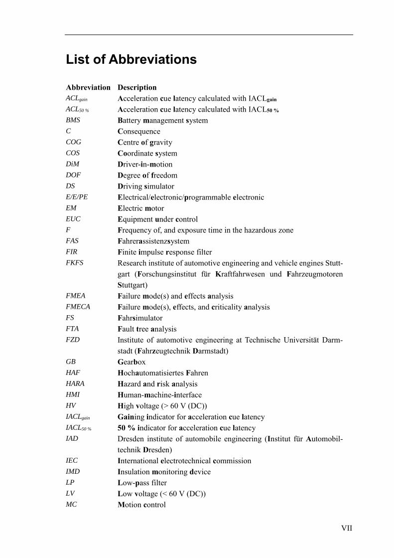
Abbreviation Description
ACLgain Acceleration cue latency calculated with IACLgain
ACL50 % Acceleration cue latency calculated with IACL50 %
BMS Battery management system
C Consequence
COG Centre of gravity
COS Coordinate system
DiM Driver-in-motion
DOF Degree of freedom
DS Driving simulator
E/E/PE Electrical/electronic/programmable electronic
EM Electric motor
EUC Equipment under control
F Frequency of, and exposure time in the hazardous zone
FAS Fahrerassistenzsystem
FIR Finite impulse response filter
FKFS Research institute of automotive engineering and vehicle engines Stutt-
gart (Forschungsinstitut für Kraftfahrwesen und Fahrzeugmotoren
Stuttgart)
FMEA Failure mode(s) and effects analysis
FMECA Failure mode(s), effects, and criticality analysis
FS Fahrsimulator
FTA Fault tree analysis
FZD Institute of automotive engineering at Technische Universität Darm-
stadt (Fahrzeugtechnik Darmstadt)
GB Gearbox
HAF Hochautomatisiertes Fahren
HARA Hazard and risk analysis
HMI Human-machine-interface
HV High voltage (> 60 V (DC))
IACLgain Gaining indicator for acceleration cue latency
IACL50 % 50 % indicator for acceleration cue latency
IAD Dresden institute of automobile engineering (Institut für Automobil-
technik Dresden)
IEC International electrotechnical commission
IMD Insulation monitoring device
LP Low-pass filter
LV Low voltage (< 60 V (DC))
MC Motion control
VIII
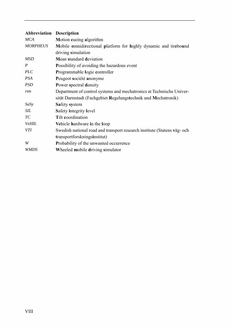
Abbreviation Description
MCA Motion cueing algorithm
MORPHEUS Mobile omnidirectional platform for highly dynamic and tirebound
driving simulation
MSD Mean standard deviation
P Possibility of avoiding the hazardous event
PLC Programmable logic controller
PSA Peugeot société anonyme
PSD Power spectral density
rtm Department of control systems and mechatronics at Technische Univer-
sität Darmstadt (Fachgebiet Regelungstechnik und Mechatronik)
SaSy Safety system
SIL Safety integrity level
TC Tilt coordination
VeHIL Vehicle hardware in the loop
VTI Swedish national road and transport research institute (Statens väg- och
transportforskningsinstitut)
W Probability of the unwanted occurrence
WMDS Wheeled mobile driving simulator

IX
List of Symbols and Indices
Symbol Unit Description
a m/s² Acceleration
b m Workspace
C ./. Dimensionless tuning parameter
d m, ./. Displacement, dimensionless damping constant
e ./. Dimensionless equivalency factor
E J, Wh Energy
f Hz, ./. Frequency, dimensionless coefficient
F N Force
g m/s² Gravitational constant (= 9.81 m/s²)
G 1 Transfer function
h m Height
I A Electric current
l m Length
m kg Mass
n ./. Amount
P W Power
r m Radius
s rad/s Laplace (complex frequency) operator
t s Time
T Nm Torque
U V Electric voltage
v m/s Velocity
𝛼 ° Slip angle
𝛽 ° Tilt angle
𝛿 ° Steering angle
𝜂 ./. Efficiency
𝜃 kgm² Moment of inertia
µ ./. Coefficient of friction
𝜎 ./. Standard deviation
𝜏 s Time constant (e.g. feedback gain)
𝜓 ° Yaw angle
𝜔 rad/s Wheel speed
𝛵 1/s Inverted time constant
X
Index Description
DS Driving simulator(-fixed)
dyn Dynamic
E Earth-fixed
el Electric
em Energy model
hor Horizontal
i Count (from 1 to maximum)
I Inertial
lat Lateral
lim Limitation
long Longitudinal
nom nominal
R Resistance
sim Simulation
t Triangle
trans Translational
V Vehicle(-fixed)
W Wheel(-fixed)
𝑥 Surge DOF
𝑦 Sway DOF
𝑧 Heave DOF
𝜃 Pitch DOF
𝜑 Roll DOF
𝜓 Yaw DOF
XI
Kurzfassung
Der automobile Entwicklungsfokus verschiebt sich von der Entwicklung von Fahreras-
sistenzsystemen (FAS) hin zu (hoch-)automatisiertem Fahren (HAF), wie der Tagespresse
entnommen werden kann. Dabei sind sich Experten einig, dass Fahrsimulatoren (FS) bei
der Absicherung von HAF eine noch wichtigere Rolle zukommen wird, also schon bei
FAS. Der Stand der Technik der FS befindet sich in Bezug auf die Wiedergabequalität
von Beschleunigungen jedoch in einer Sackgasse, da die gestellten Dynamikanforderun-
gen nicht ökonomisch erfüllt werden können, was die Validität der im FS erzielten Ergeb-
nisse beeinträchtigt und somit ein bahnbrechendes, neues Konzept auf den Plan ruft.
Deshalb wird hier das Konzept eines selbstfahrenden Fahrsimulators (WMDS) unter-
sucht, um bei mindestens gleichwertiger Immersion des Probanden und reduzierten Kos-
ten den Stand der Technik zu ersetzen. Diese Arbeit beleuchtet das übergeordnete Pro-
jektziel des Machbarkeitsnachweises von WMDS unter zwei Gesichtspunkten: Ist die
selbstfahrende Plattform praktisch in der Lage die gleiche Horizontaldynamik, wie sie in
einem realen Fahrzeug auftritt, in Bezug auf Leistungsbedarf, Energiebedarf und Bewe-
gungslatenz abzubilden, sowie welche Funktionen und Überwachungsmaßnahmen sind
erforderlich, um das von einem WMDS ausgehende Risiko auf ein akzeptables Niveau
zu reduzieren?
Die erste Forschungsfrage wird mittels Fahrversuchen mit dem skalierten WMDS-
Prototyp MORPHEUS untersucht. Da aufgrund der begrenzten Fahrfläche für
MORPHEUS keine unskalierten Stadtfahrmanöver durchführbar sind, wird ein Leis-
tungs-/Energiemodell entwickelt, parametrisiert und validiert, mit dem ein unskalierter
Energiebedarf sowie der Leistungsbedarf in Abhängigkeit des Skalierungsfaktors simu-
liert werden. Der Leistungs- und Energiebedarf sowie die Anforderungen an die Bewe-
gungslatenz sind nachweislich mit dem Stand der Technik erfüllbar.
Die zweite Forschungsfrage wird untersucht, indem eine Gefahren- und Risikoanalyse
durchgeführt wird und daraus Sicherheitsanforderungen abgeleitet werden. Eine Sicher-
heitsarchitektur wird entworfen, wobei ein autarkes Notbremssystem das Kernelement
darstellt. Eine exemplarische Ausführung der Architektur wird auf die erreichte Risikore-
duktion sowie auf neuerlich generierte Gefahren durch die dem System hinzugefügten
Komponenten und Funktionen untersucht und weist nach, dass keine unakzeptablen Ri-
siken mehr vorhanden sind.
Zusammenfassend liefert die vorliegende Dissertationsschrift den nächsten Baustein zum
Machbarkeitsnachweis von WMDS und damit zur Revolution der FS-Technologie.
XII
Short Summary
The automotive development focus shifts from advanced driver assistance systems to-
wards automated driving, as can easily be concluded from daily news. While the valida-
tion and verification of driver assistance systems is already challenging, the question of
how to validate automated driving is still unanswered. Nevertheless, it is widely agreed
that the importance of Driving Simulators (DS) for the validation of driver assistance
systems will increase even further for the validation of automated driving. Still, state-of-
the-art DS are in a deadlock when it comes to providing the demanded quality in motion
representation because larger workspaces are needed but cannot be provided economi-
cally, thus, impeding validity of DS results and calling for a ground-breaking concept.
A Wheeled Mobile DS (WMDS) is researched at FZD to replace state-of-the-art DS while
providing an at least equal immersion to the test person with reduced costs. Therefore,
this thesis investigates the superordinate project goal of proving feasibility of WMDS
from two viewpoints: Firstly, is the wheeled motion base practically capable of providing
the horizontal dynamics as they would occur in a real car in the aspects power demand,
energy demand, and motion latency. Secondly, what measures are needed to reduce the
risk that arises from the unbound system to an acceptable level and how are these
measures triggered and monitored, ergo: How would a safety architecture need to look
like for a WMDS?
The first research question is addressed by conducting driving manoeuvres with the scaled
WMDS prototype MORPHEUS. As unscaled urban driving manoeuvres cannot be driven
with MORPHEUS, since the available driving areas are not large enough, a power/energy
model is developed, parameterised, and validated, enabling the simulation of the unscaled
energy demand and of the power demand in dependence of the scaling factor. Concluding,
the requirements to power and energy demand as well as motion latency can be fulfilled
by state-of-the-art technology.
To answer the second research question, a state-of-the-art hazard and risk analysis has
been conducted and safety requirements have been derived. An overall safety architecture
is designed for these safety requirements, whereas the core element is an autarchic emer-
gency braking system. An exemplary design of this safety architecture is investigated and
evaluated in terms of risk reduction and additional hazards arising from the newly intro-
duced functions and components, yielding that no unacceptable risk is inherited in the
system.
Concluding, the herein presented work provides the next building block towards proving
general feasibility of WMDS and, thus, towards revolutionising DS technology.
1
1 Introduction
1.1 Motivation
As already mentioned in the summary, the automotive development focus shifts from
advanced driver assistance systems (SAE Level 0-21) towards automated driving (SAE
Level 3-51) and the importance of Driving Simulators (DS) for the validation of advanced
driver assistance systems2,3,4,5,6 as well as of automated driving7,8,9 is undisputed, espe-
cially for urban applications. Not to mention other areas of application that will remain
relevant in near future such as driver behaviour analysis, Human-Machine Interface
(HMI) development and validation, and dimensioning of chassis components3,4,6,10. This
continuing interest in DS is due to its key advantages reproducibility, e.g. in studies in-
volving many test subjects undergoing the same driving scenario, safety for the subject,
e.g. when investigating safety critical driving manoeuvres such as an emergency evasion,
and – of course – cost and time reduction in the development process due to the early
availability of virtual prototypes.
When looking back at the historic development of DS, a trend towards more realistic – in
terms of motion feedback – driving simulation becomes evident: In the late 1950s the first
fixed-base DS were developed, succeeded by dynamic DS with Stewart platforms in the
late 1960s. It was not until the end of the 20th century that highly dynamic DS were de-
veloped, employing xy-rails for a better representation of high frequent and/or sustaining
1 SAE: Terms Related to Automated Driving Systems (2014).
2 Zeeb, E.: Daimler’s New Full-Scale, High-Dynamic DS (2010).
3 Baumann, G. et al.: How to Build Europe’s Largest Eight-Axes DS (2012).
4 Blana, E.: A Survey of DS Around the World (1996). a: pp. 4-7.
5 Chapron, T.; Colinot, J.-P.: The New PSA Advanced DS (2007).
6 Schöner, H.-P.: Erprobung und Absicherung im dynamischen DS (2014).
7 Richter, A.; Scholz, M.: The Surveyor’s Guide to Automotive Simulation (2016).
8 Boer, E. R. et al.: The Role of DS in Developing and Evaluating AD (2015).
9 Maurer, M. et al.: Autonomes Fahren (2015). p. 446.
10 Schöner, H.-P.; Morys, B.: Dynamische DS (2015). p. 140.
1 Introduction
2
translational accelerations11. Many efforts were undertaken after that to increase the qual-
ity of the acceleration representation and therefore the immersion as well. However, large
workspaces are required to provide the equal acceleration sensation as in a real car, with
urban driving – which requires the highest developmental effort for automated driving –
being the worst-case application scenario12. This dilemma was accurately summarised by
Zeeb, former head of Daimler DS, in 2010: “To induce a much better longitudinal motion
sensation with a scaling factor close to 1:1 for all possible acceleration and deceleration sce-
narios even a several ten meter long sledge would not be sufficient, but would increase the
technical and financial effort tremendously, especially when the […] mandatory requirements
for drive dynamic experiments have to be fulfilled”13.
The prescribed controversy – the increasing importance of highly realistic DS for automotive
research and development vs. the dynamic limitations of state-of-the-art highly dynamic DS
– calls for a ground-breaking new concept. Thus, this work focuses on the advancement and
proof of feasibility of the Wheeled Mobile Driving Simulator (WMDS) that is investigated
by the Institute of Automotive Engineering (Fachgebiet Fahrzeugtechnik FZD) at Technische
Universität Darmstadt since 2010.
1.2 Wheeled Mobile Driving Simulator Research
at FZD
This section gives a brief overview of the WMDS research and its methodology at FZD.
The herein described hypotheses are used throughout the entire project and will partially
be investigated in this thesis. Thus, this section will enable the reader to rank the scientific
merit of this thesis among FZD’s overall WMDS research scope.
1.2.1 Overall Project Goal
Because setting up a WMDS is a tremendous effort – in economical and labour terms –
the feasibility of the concept must be proven beforehand. Thus, the overall project goal is
to demonstrate that FZD’s WMDS concept can replace state-of-the-art DS with equal or
higher immersion of the test person while costs are decreased compared to enhanced
Stewart motion base DS (e.g. DS with compound slides). For being able to scientifically
research feasibility, this overall project goal is stipulated as the main hypothesis H1:
11 Blana, E.: A Survey of DS Around the World (1996).
12 Betz, A. et al.: Motion Analysis of a WMDS (2012). pp. 5f.
13 Zeeb, E.: Daimler’s New Full-Scale, High-Dynamic DS (2010). p. 162.
1.2 Wheeled Mobile Driving Simulator Research at FZD
3
H1: FZD’s WMDS concept is able to provide equal or higher immersion to the test
person while acquisition and maintenance costs are decreased compared to state-of-
the-art enhanced Stewart motion base DS.
The hypothesis succeeds if all attempts of falsification fail. The soundest falsification test
is to build a WMDS, evaluate the immersion in a representative study with test persons,
and calculate the costs. Unfortunately, as initially described, the stakes for conducting this
test are high and the outcome is uncertain. Therefore, criteria must be identified that bear
the potential to falsify the main working hypothesis in theory and practical applications.
Thus, the risk of bad investments is reduced. These criteria are referred to as falsification
aspects and must be researched in worst-case scenarios so that no trivial verifications (e.g.
comparing the high-fidelity WMDS concept with a low-fidelity DS) are conducted. If the
aspects’ investigations fail to falsify the hypothesis in theory or practical application, the
concept is considered feasible.
1.2.2 Initial Situation
Previously conducted work at FZD, conducted by Betz14, analysed the following five fal-
sification aspects:
1. Power demand (theoretical)
2. Energy demand (theoretical)
3. Friction coefficient (practical application)
4. Motion control (theoretical)
5. Safety architecture (exemplary practical application of an emergency braking sys-
tem)
Whereas the falsification aspects power and energy demand as well as motion control
have been analysed theoretically in a virtual prototype (cf. section 5.2), the friction coef-
ficient and the safety architecture were investigated with a hardware prototype that was
designed and manufactured in the author’s master’s thesis15 and is described in detail in
chapter 3. While the aspect friction coefficient was not able to falsify the working hy-
pothesis, the safety concept has only been exemplarily demonstrated by an emergency
braking system integrated into the hardware prototype. Neither risk has been assessed,
nor the triggering and fault monitoring mechanism has been set up. Thus, the falsification
aspect of a safety architecture has not been sufficiently investigated, yet.
14 Betz, A.: Diss., Feasibility Analysis and Design of WMDS (2015).
15 Wagner, P.: Master's thesis, Aufbau und Inbetriebnahme eines WMDS (2013).
1 Introduction
4
1.2.3 Working Hypotheses
Besides Betz’ five falsification aspects, two additional falsification aspects are identified,
whereas the aspect of vertical dynamics is analysed by Zöller, who already published
parts of his findings16,17:
6. Latency
7. Vertical dynamics
Concluding, the seven falsification aspects are transferred into working hypotheses that
are derived from the main hypothesis and must be researched within the overall project
scope. Again, this thesis covers neither all hypotheses nor all falsification aspects.
1.2.3.1 Wheeled Motion Base
The working hypothesis H1.1 is adapted from Betz and addresses the five falsification
aspects power demand, energy demand, friction coefficient, motion control, and motion
latency:
H1.1: “The wheeled motion base of [FZD’s] WMDS [concept] with its dynamics lim-
ited by friction forces can simulate the horizontal dynamics of urban traffic for normal
driver behaviour considering common scaling factors”18.
“The two restrictions of the hypothesis concerning normal driver behaviour and common
scaling factors are stipulated because no effort is desired that causes higher requirements
than necessary. First, the driving experience that is intended to be reproduced in the DS
is limited in its dynamics due to the driving behaviour of normal drivers. In other words,
no expert or race car drivers are considered, and the road traffic regulations are obeyed.
Second, advantage is gained from the common scaling factors as they are found in litera-
ture because human perception may be fooled in certain ranges without causing disturbing
losses in the perceived driving experience [(further details can be found in sections 2.1.4
to 2.1.6 and 2.5.2)]”18.
1.2.3.2 Safety Architecture
Hypothesis H1.2 addresses the falsification aspect of a suitable safety architecture:
H1.2: FZD’s WMDS concept does not bear an unacceptable risk to a human under any
environmental conditions and in any use case.
16 Zöller, C. et al.: Tire Concept Investigation for WMDS (2016).
17 Zöller, C. et al.: Tires and Vertical Dynamics of WMDS (2017).
18 Cf. Betz, A.: Diss., Feasibility Analysis and Design of WMDS (2015). p. 4.
1.3 Overall Methodology and Structure of the Thesis
5
FZD’s WMDS concept is characterised by its ability to move freely on a planar surface,
which excludes stop dampers from being used, as it is currently done in highly dynamic
DS. An unacceptable risk is context-dependent and is “judged to be unacceptable [..] ac-
cording to valid societal moral concepts”19. For technical systems, various approaches
exist that evaluate the risk based on risk parameters determined in a thorough analysis
(section 2.3). Thus, the WMDS and its safety architecture must comply with state-of-the-
art norms (e.g. IEC 61508) and guidelines (e.g. VDI 2221). Humans interacting with the
WMDS must be considered in the design of the safety architecture. Hypothesis H1.2 in-
cludes the operation and maintenance of the WMDS and, therefore, subjects such as test
persons, maintenance personnel, and bystanders.
1.2.3.3 Vertical Dynamics
Hypothesis H1.3 addresses the falsification aspect of the vertical dynamics excitation re-
sulting from the tire road contact:
H1.3: FZD’s WMDS concept can simulate urban driving scenarios on any driving sur-
face, which is commonly driven on with WMDS, without impairing the test person’s
immersion.
Common driving surfaces for the application of WMDS must be defined because the con-
cept is unprecedented worldwide. Potential users of WMDS can help by considering on
which surfaces they would use a WMDS. In this hypothesis’ context, the immersion refers
to vertical excitations that do not disturb the overall driving experience of the test person.
Values can be found in literature or in experiments.
1.3 Overall Methodology and Structure of the
Thesis
This thesis researches the falsification aspects of practical power demand, energy de-
mand, and latency of hypothesis H1.1 and the theoretical falsification aspect of a safety
architecture, hypothesis H1.2. The aim is to identify the worst-case for each aspect under
the given constraints (e.g. normal driver behaviour) and with state-of-the-art technology
to conduct a most rigorous falsification.
19 ISO TC 22/SC 32 Electrical and electronic components and general system aspects: ISO 26262 (2011).
p. 18.
1 Introduction
6
1.3.1 Wheeled Motion Base
The research questions that are investigated for the falsification of hypothesis H1.1 are:
1. Power demand: Is FZD’s WMDS concept capable of providing the maximum
power demanded with state-of-the-art components (actuators, on-board power
supply systems, tires, suspension, etc.)?
2. Energy demand: Are state-of-the-art on-board energy storage systems capable of
providing the energy required for driving simulation as described by hypothesis
H1.1?
3. Latency: Which motion latency from the driver’s input to the provided accelera-
tion cue must be undercut and is FZD’s WMDS concept capable of providing cues
within this latency in order to represent the same motion sensation as in standard
passenger cars?
Sections 2.4 to 2.5 describe the state-of-the-art of accumulators and human motion per-
ception. This knowledge allows to extrapolate from the capabilities of the hardware pro-
totype to what can be achieved, defining the worst-case requirements and constraints for
the experiments (sections 4.1 to 4.3, in which the detailed methodology with the experi-
mental setup and evaluation criteria can be found). A bottom-up methodology is applied
for identifying the worst-case power demand, energy demand, and latency of FZD’s
WMDS concept. The investigation is done with real driving of the hardware prototype,
starting from simple manoeuvres evolving into more complex manoeuvres, section 5.1.
Because not all falsification experiments can be conducted on a 1:1 scale, the investiga-
tion is supported by a virtual prototype, section 5.2. If the required outputs of the virtual
prototype are validated with the hardware prototype, the simulation results can be extrap-
olated, section 6. If these aspects cannot be falsified, they are practically feasible.
1.3.2 Safety Architecture
For the falsification of hypothesis H1.2, the worst-case risks any human is exposed to in
all possible use cases, as defined in hypothesis H1.1, must be determined. Then, the re-
search question is if these risks can be reduced to an acceptable level by a safety archi-
tecture. Relevant functional safety standards are described in section 2.3. The safety ar-
chitecture itself is deduced from a top-down methodology. This implies that the safety
architecture development is started by identifying all hazards (section 7.1.2, methodology
section 4.4.2). Based on the identified hazards, risk is assessed (sections 7.1.3 and 7.2,
methodology sections 4.4.3 and 4.4.4). All hazards with significant risk are included in a
safety requirement list and a safety architecture design per state-of-the-art norms and
guidelines (section 2.3) is proposed (section 7.3). The risk reduction as well as new haz-
ards introduced to the system are evaluated for an exemplary application (section 7.3.3).
Finally, an outlook to a safety architecture for full-scale WMDS is given (section 7.4).
7
2 State-of-the-Art and Scientific Research
This chapter starts with clarifying the used DS specific terminology (section 2.1, compat-
ible with Betz’20 definitions), followed by a brief overview of different types of DS with
a detailed description of wheeled mobile DS (section 2.2). Finally, the required basic in-
formation (i.e. requirements) for investigating the falsification aspects safety architecture
(section 2.3), energy demand (section 2.4), and latency (section 2.5) is addressed.
2.1 Definitions
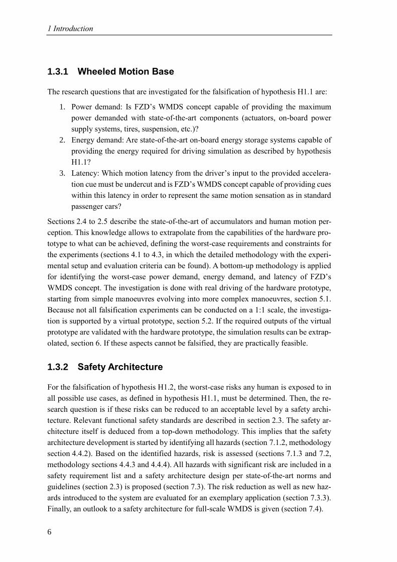
2.1.1 Coordinate System (COS)
The Coordinate System (COS) is chosen per DIN ISO 885521a, where the index E repre-
sents the earth-fixed COS and V represents the vehicle’s (in this context virtual vehicle)
COS. Additionally, in this work the indices DS for the DS’ COS and W for the wheel’s
COS are introduced. The translational Degrees Of Freedom (DOF) are denominated 𝑥 for
surge, 𝑦 for sway, and 𝑧 for heave. The rotational DOF are denominated 𝜃 for pitch, 𝜑
for roll, and 𝜓 for yaw.
Figure 2-1: COS per DIN ISO 885521b
20 Betz, A.: Diss., Feasibility Analysis and Design of WMDS (2015). pp. 9-12.
21 Deutsches Institut für Normung e. V.: ISO 8855 (2013). a: - ; b: p. 11.
2 State-of-the-Art and Scientific Research
8
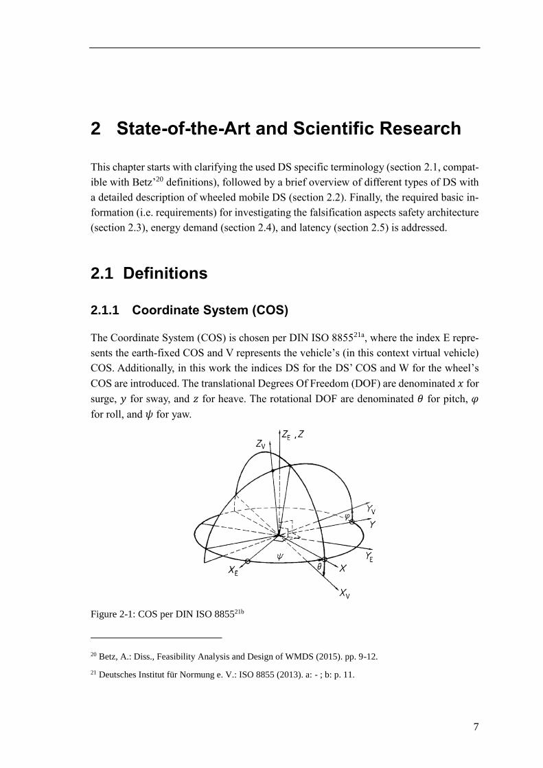
2.1.2 Simulator Orientation
The x-direction of the DS (𝑥DS) is the direction the test person’s seat is facing. According
to DIN ISO 885522, the lateral direction (𝑦DS) is positive to the left and the vertical direc-
tion (𝑧DS) upwards. The steering and drive units are numbered (1 to 3) clockwise, starting
at the unit faced by the test person’s seat, cf. Figure 2-2:
Figure 2-2: DS orientation
2.1.3 Motion Cue / Motion Cueing Algorithm (MCA)
Synonyms for the term cue are reference, indication, or information. When working with
humans, this term is commonly used for describing a sensory information that is pro-
vided23,24. Therefore, the term motion cue describes a sensory information that is per-
ceived and interpreted by the test person as motion. Because motion is primarily per-
ceived through the vestibular sensory organ (cf. section 2.5.1), the term motion cue is
used within this thesis for describing a vestibular stimulus that is presented to the subject.
The algorithm that translates motion cues of a real car into the motion cues of the DS is
referred to as the Motion Cueing Algorithm (MCA).
2.1.4 Scaling
Scaling describes the process of proportionally reducing the acceleration amplitudes
within a DS, e.g. when the acceleration amplitude of 4 m/s² of a real car is to be simulated
22 Deutsches Institut für Normung e. V.: ISO 8855 (2013).
23 Betz, A.: Diss., Feasibility Analysis and Design of WMDS (2015). p. 10.
24 Fischer, M.: Diss., MCA für eine realitätsnahe Bewegungssimulation (2009). p. 5.
𝑥DS
𝑦DS 𝑧DS
1
23
2.1 Definitions
9
in a DS with a scaling factor of 0.5, the simulated DS acceleration would be 2 m/s². Scal-
ing reduces the amplitude uniformly across all frequencies25a and not necessarily impedes
the subject’s immersion26. Commonly used scaling factors are 1, 0.7, and 0.5, depending
on the manoeuvre that is to be simulated and on available workspace limiting the accel-
eration amplitude in dependence on the acceleration frequency26,27a,28. As stated by Betz29,
it is not clear whether the yaw motion should be scaled as well. On the one hand scaling
the yaw motion would match the scaled lateral acceleration, on the other hand the un-
scaled visual cues would contradict the scaled yaw motion. Therefore, an unscaled yaw
motion is used here, resulting in a conservative investigation of WMDS.
2.1.5 Tilt Coordination (TC)
Tilt Coordination (TC) basically describes a measurement error that can occur with hu-
mans and sensors if perception is based on the measurement of inertia forces. If the sensor
(vestibular organ for a human) is tilted relative to the gravitational force vector, the sine
portion of the gravitational force is perceived as horizontal acceleration25b,27b,29. This phe-
nomenon is applicable up to certain ranges of tilt angles, tilt rates, and tilt accelerations,
often described as stationary perception thresholds (section 2.5.2). Nevertheless, this
technique is predestined for application in DS since almost all dynamic DS use motion
systems with six DOF or more that can tilt the subject. Thus, low frequent accelerations
may be well presented through TC. The frequencies are partitioned by the MCA. The
delusion may be perceived by the subject if the vestibular channel does not match the
cues from other sensory channels. Therefore, especially visual cues must adapt to TC.
2.1.6 Washout
The washout aims at minimising the required workspace. This is achieved by moving the
DS back into its initial position below human perception thresholds or by masking the
washout motion with TC27b. Usually this is done filter-based within the MCA, therefore,
the term washout is also often used for referring to the (classical) MCA25c,30.
25 Reid, L. D.; Nahon, M.: Flight Simulation MCA (1985). a: Appendix B.1; b: 1.1; c: - .
26 Greenberg, J. et al.: Lateral Motion Cues During Simulated Driving (2003).
27 Fischer, M.: Diss., MCA für eine realitätsnahe Bewegungssimulation (2009). a: pp. 57f.; b: pp. 6f.
28 Groen, E. et al.: Psychophysical Thresholds of Linear Acceleration (2000).
29 Betz, A.: Diss., Feasibility Analysis and Design of WMDS (2015). p. 11.
30 Nahon, M.; Reid, L. D.: Simulator MCA - A Designer's Perspective (1990).
2 State-of-the-Art and Scientific Research
10
2.1.7 Simulator Sickness
Simulator sickness must be avoided in driving simulation experiments and refers to an
illness-like condition whose symptoms can be nausea, vomiting, cold sweating, and pal-
lor. The most widely accepted theory behind simulator sickness is the sensory conflict
theory31, according to which simulator sickness occurs if the cues perceived by the ves-
tibular receptors, the eyes, or the non-vestibular proprioceptors mismatch. Reason and
Brand31 divide simulator sickness into two classes: The first class is caused by mismatch-
ing cues between the eyes and vestibular receptors, whereas the second class is caused by
mismatching cues between the semi-circular canals and the otoliths within the vestibular
organ (cf. section 2.5.1). While the second class is mainly influenced by a properly tuned
MCA, the first class is influenced by delayed or missing representation of one of the
aforementioned cues32. Whereas completely missing cues can be system inherent if an
insufficient or no motion system at all is used in the DS, simulator sickness induced by
delayed cues is caused by latency in either the visual representation system or the motion
system. These delayed cues are primary responsible for simulator sickness according to
literature33. Latency is dealt with in more detail in section 2.5.3.
2.2 State-of-the-Art Driving Simulators
The motion capabilities of DS have changed dramatically in the latter half of the 20th
century but did not improve much since then. This section gives a brief overview of these
motion capabilities and corresponding areas of application. The DS are ranked in the or-
der of increasing motion capability. The exemplary designs that are chosen represent top
of the class DS in terms of available acceleration amplitude and sustained acceleration. A
more in-depth analysis has been conducted by Schöner and Morys34 or more complete
analyses by Blana35 or Slob36.
31 Reason, J. T.; Brand, J. J.: Motion Sickness (1975).
32 Hettinger, L. J.; Riccio, G. E.: Visually Induced Motion Sickness (1992). p. 306.
33 St. Pierre, M. E.: Diss., The Effects of Latency on Simulator Sickness in a HMD (2012). pp. 16-18.
34 Schöner, H.-P.; Morys, B.: Dynamische DS (2015).
35 Blana, E.: A Survey of DS Around the World (1996).
36 Slob, J. J.: State-of-the-Art DS (2008).
2.2 State-of-the-Art Driving Simulators
11
2.2.1 Fixed Base DS
Fixed base simulators origin back to early flight simulators in the beginning of the 20th
century, inheriting the very basic element of a simulator: The HMI. DS in the 1960s al-
ready showed visual representation, audition was represented by the 1970s37. Therefore,
visual and audible feedback constitute the second and third basic elements of a DS.
2.2.2 Stewart Motion Base DS
A Stewart Platform – based on the universal tyre test machine by Gough38 – consists of
two platforms that are connected by six linear actuators39 and is nowadays usually re-
ferred to as hexapod. The setup allows motion in all six translational and rotational DOF.
Applied to a fixed base DS, the test subject can be moved, which results in an increased
immersion and, therewith, motion cues constitute the fourth basic element of a DS. How-
ever, due to the limited stroke of the actuators and in dependence on the acceleration
amplitude, only short acceleration cues can be represented. More advantageous, the rota-
tional DOF allow to tilt the test subject and, therefore, enable TC with sustaining accel-
eration cues but limited frequency.
2.2.3 “Robocoaster” Motion Base DS
The Robocoaster motion base DS is based on the Robocoaster robot arm for entertainment
purposes that in turn is based on a KUKA robot arm for industrial purposes40. The use of
a robot arm increases the available motion compared to a hexapod and therewith also the
immersion of the test subject. Nevertheless, accelerations still cannot be represented for
all frequencies and amplitudes that occur while driving a car. Advantageous – compared
to Stewart motion bases – is the increased yaw angle. The Max Planck Institute for Bio-
logical Cybernetics extended its Robocoaster by a linear track that adds 9.88 m of motion
envelope41. This adds to the immersion but still limits the DS in its capabilities to repre-
sent sustaining high amplitude accelerations. Further disadvantages of the concept are the
complex control and safety architecture.
37 Blana, E.: A Survey of DS Around the World (1996). pp. 4-7.
38 Gough, V. E.; Whitehall, S. G.: Universal Tyre Test Machine (1962).
39 Stewart, D.: A Platform with Six DOF (1965).
40 Teufel, H. et al.: MPI Motion Simulator (2007).
41 Nieuwenhuizen, F. M.; Bülthoff, H. H.: The MPI CyberMotion Simulator (2013). p. 124.
2 State-of-the-Art and Scientific Research
12
2.2.4 Centrifuge Motion Base DS
Desdemona Ltd. developed the Desdemona simulator based on a centrifuge. The complex
design allows translational motion as a hexapod, whereas rotational motion is possible up
to over 360°42. Combined translational and rotational motion can create sustaining accel-
eration cues with high amplitudes. Nevertheless, also unwanted acceleration cues are gen-
erated, especially when initialising or ending a manoeuvre with sustained acceleration:
The DOF are interdependent, which makes the control – in terms of the MCA – complex.
2.2.5 Cable Robot DS
In 2015, the Max Planck Institute for Biological Cybernetics introduced their cable robot
DS. This DS is suspended by eight cables, each driven by an individual electric motor,
enabling the usage of the entire room (5 x 8 x 5 m³)43. Advantageous are the light concept
and high acceleration amplitudes. Disadvantageous are elasticities of the cables that can
result in vibration or latency in acceleration representation. Furthermore, to represent sus-
tained high amplitude acceleration, the room and with that the length of the cables must
be increased, worsening the elasticity issue. These disadvantages impede the use of cable
robots for (nearly) unscaled high-fidelity driving simulation.
2.2.6 Enhanced Stewart Motion Base DS
Today’s high-fidelity DS still employ a hexapod that is either carried on compound slides
or by air cushions enhanced by further actuators. For the air cushion solution, linear ac-
tuators are used that connect to the hexapod motion base. Compound slide solutions may
also use rotary actuators. Whereas the hexapod is used for TC and rotational movement
of the car, the additional actuators are used to represent high frequency accelerations, i.e.
accelerations that cannot be represented by TC due to the human motion perception
thresholds (see section 2.1.5 and 2.5.2). Of course, adding a slide increases the weight of
the DS significantly and, even worse, adding a crossbeam for the second slide exponen-
tiates this issue since the first slide(s) must be moved together with the hexapod, cabin,
etc. Power and energy demand are affected by the weight increase, too. Therefore, a nat-
ural trade-off between DS fidelity and economy seems to be given, as confirmed by
Zeeb44 (citation section 1.1). For comparatively smaller solutions, the hexapod can be
carried by air cushions instead of slides, which reduces the moving mass. For spanning
42 Wentink, M. et al.: Design and Evaluation of MCA for Desdemona Simulator (2005). p. 2.
43 Max Planck Institute for Biological Cybernetics: CableRobot with Passenger (2015).
44 Zeeb, E.: Daimler’s New Full-Scale, High-Dynamic DS (2010). p. 162.
2.2 State-of-the-Art Driving Simulators
13
large workspaces, the stiffness of the actuators’ pistons becomes critical. Nevertheless,
more and more enhanced Stewart motion base DS are built around the world as can be
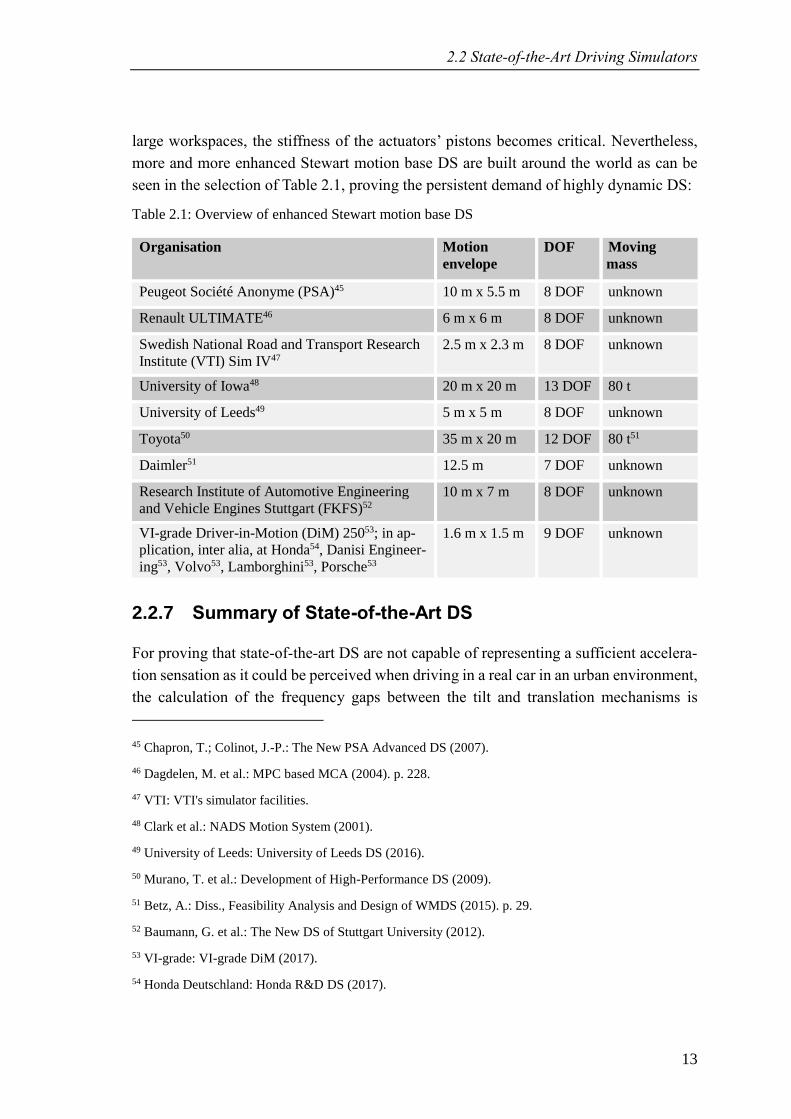
seen in the selection of Table 2.1, proving the persistent demand of highly dynamic DS:
Table 2.1: Overview of enhanced Stewart motion base DS
Organisation Motion
envelope
DOF Moving
mass
Peugeot Société Anonyme (PSA)45 10 m x 5.5 m 8 DOF unknown
Renault ULTIMATE46 6 m x 6 m 8 DOF unknown
Swedish National Road and Transport Research
Institute (VTI) Sim IV47
2.5 m x 2.3 m 8 DOF unknown
University of Iowa48 20 m x 20 m 13 DOF 80 t
University of Leeds49 5 m x 5 m 8 DOF unknown
Toyota50 35 m x 20 m 12 DOF 80 t51
Daimler51 12.5 m 7 DOF unknown
Research Institute of Automotive Engineering
and Vehicle Engines Stuttgart (FKFS)52
10 m x 7 m 8 DOF unknown
VI-grade Driver-in-Motion (DiM) 25053; in ap-
plication, inter alia, at Honda54, Danisi Engineer-
ing53, Volvo53, Lamborghini53, Porsche53
1.6 m x 1.5 m 9 DOF unknown
2.2.7 Summary of State-of-the-Art DS
For proving that state-of-the-art DS are not capable of representing a sufficient accelera-
tion sensation as it could be perceived when driving in a real car in an urban environment,
the calculation of the frequency gaps between the tilt and translation mechanisms is
45 Chapron, T.; Colinot, J.-P.: The New PSA Advanced DS (2007).
46 Dagdelen, M. et al.: MPC based MCA (2004). p. 228.
47 VTI: VTI's simulator facilities.
48 Clark et al.: NADS Motion System (2001).
49 University of Leeds: University of Leeds DS (2016).
50 Murano, T. et al.: Development of High-Performance DS (2009).
51 Betz, A.: Diss., Feasibility Analysis and Design of WMDS (2015). p. 29.
52 Baumann, G. et al.: The New DS of Stuttgart University (2012).
53 VI-grade: VI-grade DiM (2017).
54 Honda Deutschland: Honda R&D DS (2017).
2 State-of-the-Art and Scientific Research
14
stressed55: It is assumed that a longitudinal, harmonic excitation with an amplitude |�̂�| of
5 m/s² is to be presented. The translation system is then limited by the available work-
space, resulting in the lower limit frequency for translation, where 2𝑏 is the available
workspace:
𝑓trans,lim >1
2𝜋√|�̂�|
𝑏 (2-1)
The tilt system (namely the hexapod) is then limited by the tilt rate threshold �̇�threshold,
resulting in the upper limit frequency for tilting:
𝑓tilt,lim ≲1
2𝜋
𝑔
|�̂�|�̇�threshold (2-2)
To be able to represent the acceleration demand, the lower limit frequency for the trans-
lation system must meet the upper limit frequency for the tilt system. Obviously, the hu-
man perception threshold for tilt rate cannot be changed. Therefore, if scaling is left out,
the only available parameter to be changed is the workspace 𝑏, yielding for 𝑓trans,lim =
𝑓tilt,lim
𝑏 =|�̂�|3
𝑔2�̇�threshold2
(2-3)
Applying the tilt rate threshold that is used throughout the project of 6 °/s yields (sec-
tion 2.5.2), whereas the workspace must be provided for acceleration and deceleration as
well, yields:
𝑏(�̇�threshold = 6 °
s, |�̂�| = 5
m
s²) = ±118.4 m (2-4)
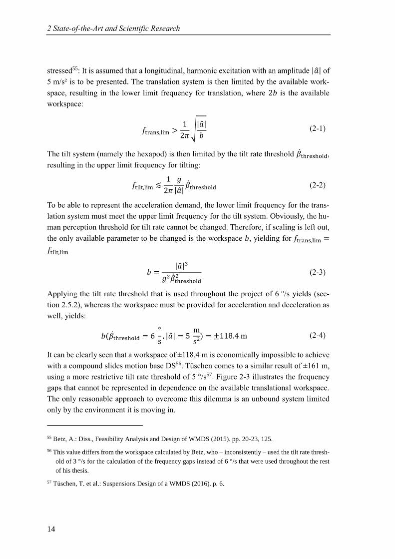
It can be clearly seen that a workspace of ±118.4 m is economically impossible to achieve
with a compound slides motion base DS56. Tüschen comes to a similar result of ±161 m,
using a more restrictive tilt rate threshold of 5 °/s57. Figure 2-3 illustrates the frequency
gaps that cannot be represented in dependence on the available translational workspace.
The only reasonable approach to overcome this dilemma is an unbound system limited
only by the environment it is moving in.
55 Betz, A.: Diss., Feasibility Analysis and Design of WMDS (2015). pp. 20-23, 125.
56 This value differs from the workspace calculated by Betz, who – inconsistently – used the tilt rate thresh-
old of 3 °/s for the calculation of the frequency gaps instead of 6 °/s that were used throughout the rest
of his thesis.
57 Tüschen, T. et al.: Suspensions Design of a WMDS (2016). p. 6.
2.2 State-of-the-Art Driving Simulators
15
Figure 2-3: Frequency gaps of state-of-the-art DS (Hexapod ±1 m, compound slides motion base
DS ±10 m, unrestricted ±118.4 m)58
2.2.8 State-of-Research: Wheeled Motion Base DS
2.2.8.1 BMW Patent
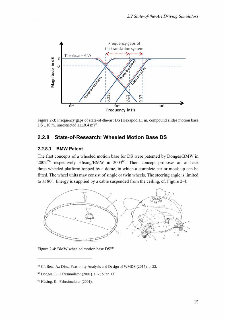
The first concepts of a wheeled motion base for DS were patented by Donges/BMW in
200259a respectively Hüsing/BMW in 200360. Their concept proposes an at least
three-wheeled platform topped by a dome, in which a complete car or mock-up can be
fitted. The wheel units may consist of single or twin wheels. The steering angle is limited
to ±180°. Energy is supplied by a cable suspended from the ceiling, cf. Figure 2-4:
Figure 2-4: BMW wheeled motion base DS59b
58 Cf. Betz, A.: Diss., Feasibility Analysis and Design of WMDS (2015). p. 22.
59 Donges, E.: Fahrsimulator (2001). a: - ; b: pp. 6f.
60 Hüsing, K.: Fahrsimulator (2001).
2 State-of-the-Art and Scientific Research
16
The safety architecture is described as an infrastructural element that obstructs the move-
ment of the DS as soon as the workspace is left. Betz61 described the drawbacks of
BMW’s concept. Firstly, it is unclear why the steering angle is limited to ±180°. Because
the cabin’s yaw angle and the DS’ trajectory are dependent on each other, the limitation
of the steering angle reduces the capabilities of the washout algorithm that drives the DS
back into its initial position. Furthermore, the described safety architecture bears a signif-
icant infrastructural effort, because the whole workspace must be framed, and the safety
infrastructure must cope with any impact speed and angle of the DS. Also, when it comes
to mobile applications, e.g. on outdoor testing grounds, an infrastructural safety architec-
ture is unsuitable.
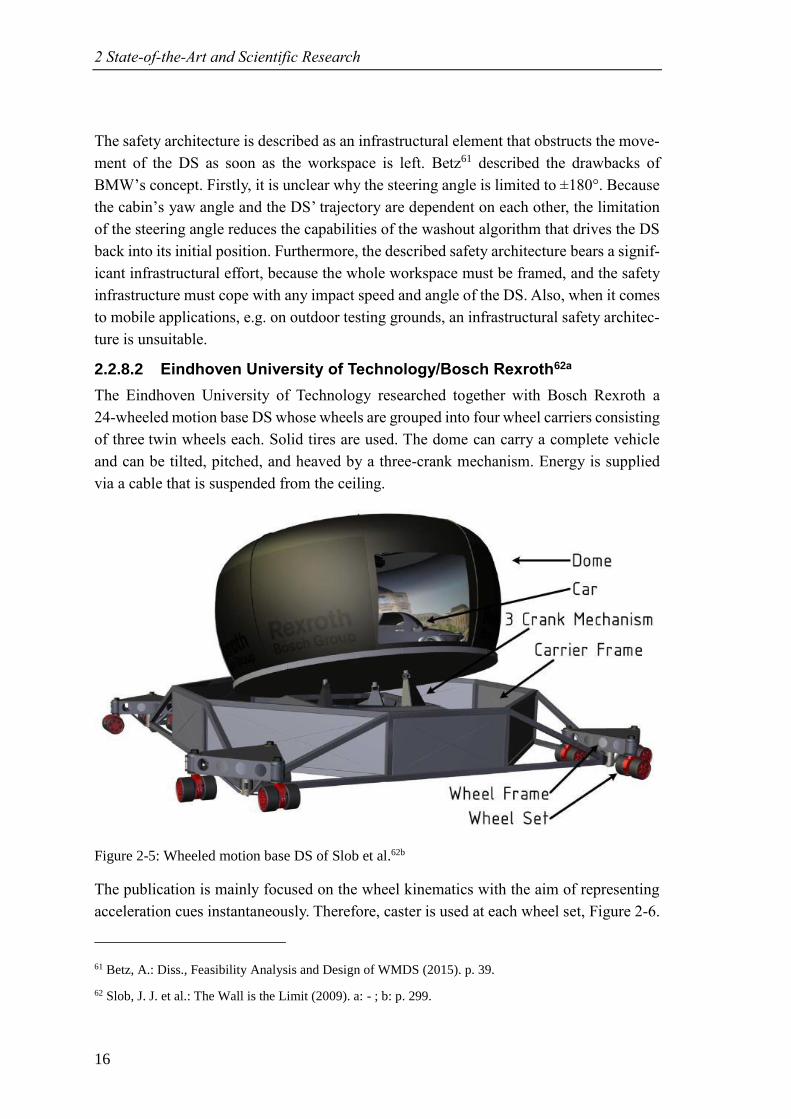
2.2.8.2 Eindhoven University of Technology/Bosch Rexroth62a
The Eindhoven University of Technology researched together with Bosch Rexroth a
24-wheeled motion base DS whose wheels are grouped into four wheel carriers consisting
of three twin wheels each. Solid tires are used. The dome can carry a complete vehicle
and can be tilted, pitched, and heaved by a three-crank mechanism. Energy is supplied
via a cable that is suspended from the ceiling.
Figure 2-5: Wheeled motion base DS of Slob et al.62b
The publication is mainly focused on the wheel kinematics with the aim of representing
acceleration cues instantaneously. Therefore, caster is used at each wheel set, Figure 2-6.
61 Betz, A.: Diss., Feasibility Analysis and Design of WMDS (2015). p. 39.
62 Slob, J. J. et al.: The Wall is the Limit (2009). a: - ; b: p. 299.
2.2 State-of-the-Art Driving Simulators
17
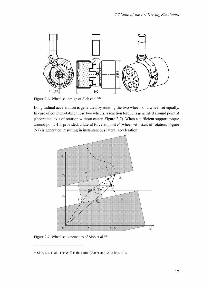
Figure 2-6: Wheel set design of Slob et al.63a
Longitudinal acceleration is generated by rotating the two wheels of a wheel set equally.
In case of counterrotating those two wheels, a reaction torque is generated around point A
(theoretical axis of rotation without caster, Figure 2-7). When a sufficient support torque
around point A is provided, a lateral force at point P (wheel set’s axis of rotation, Figure
2-7) is generated, resulting in instantaneous lateral acceleration.
Figure 2-7: Wheel set kinematics of Slob et al.63b
63 Slob, J. J. et al.: The Wall is the Limit (2009). a: p. 299; b: p. 301.
2 State-of-the-Art and Scientific Research
18
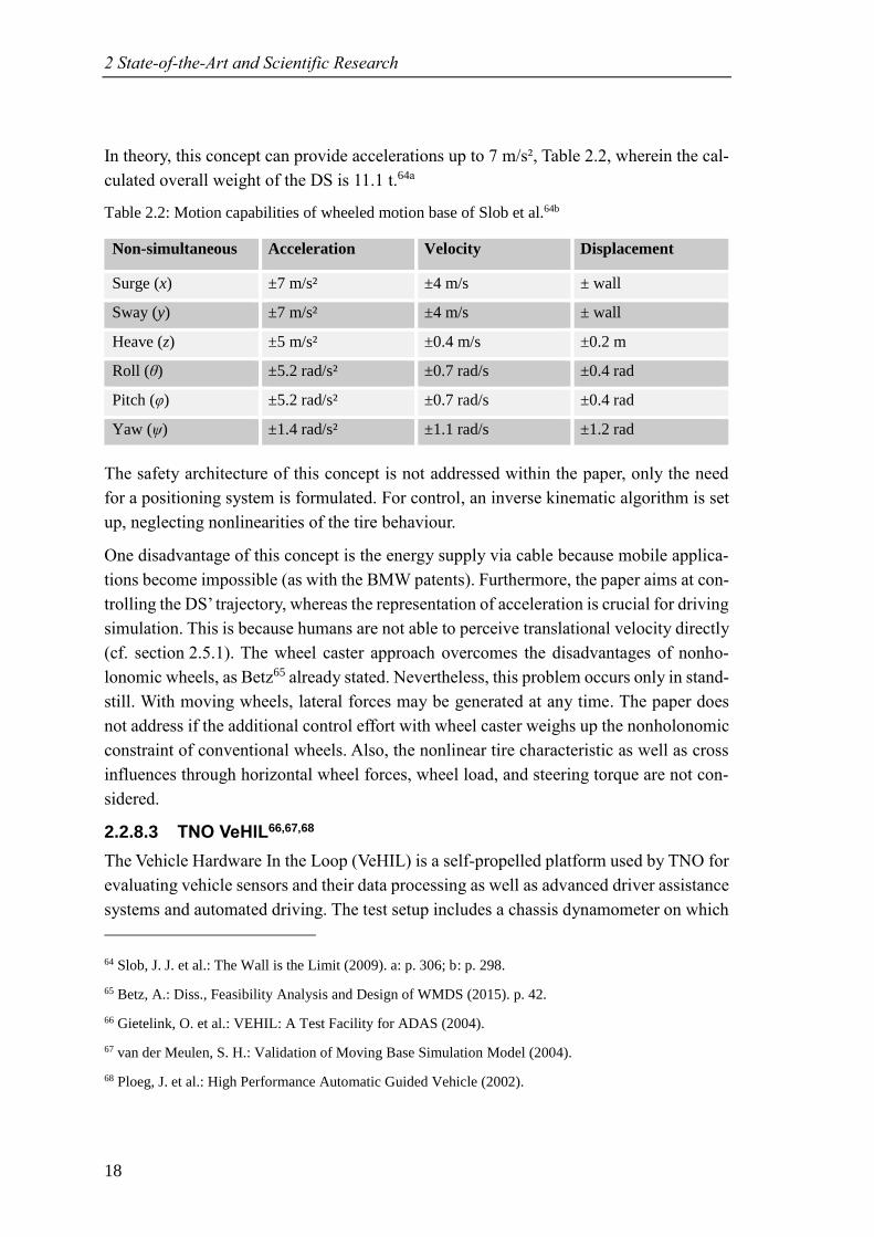
In theory, this concept can provide accelerations up to 7 m/s², Table 2.2, wherein the cal-
culated overall weight of the DS is 11.1 t.64a
Table 2.2: Motion capabilities of wheeled motion base of Slob et al.64b
Non-simultaneous Acceleration Velocity Displacement
Surge (x) ±7 m/s² ±4 m/s ± wall
Sway (y) ±7 m/s² ±4 m/s ± wall
Heave (z) ±5 m/s² ±0.4 m/s ±0.2 m
Roll (θ) ±5.2 rad/s² ±0.7 rad/s ±0.4 rad
Pitch (φ) ±5.2 rad/s² ±0.7 rad/s ±0.4 rad
Yaw (ψ) ±1.4 rad/s² ±1.1 rad/s ±1.2 rad
The safety architecture of this concept is not addressed within the paper, only the need
for a positioning system is formulated. For control, an inverse kinematic algorithm is set
up, neglecting nonlinearities of the tire behaviour.
One disadvantage of this concept is the energy supply via cable because mobile applica-
tions become impossible (as with the BMW patents). Furthermore, the paper aims at con-
trolling the DS’ trajectory, whereas the representation of acceleration is crucial for driving
simulation. This is because humans are not able to perceive translational velocity directly
(cf. section 2.5.1). The wheel caster approach overcomes the disadvantages of nonho-
lonomic wheels, as Betz65 already stated. Nevertheless, this problem occurs only in stand-
still. With moving wheels, lateral forces may be generated at any time. The paper does
not address if the additional control effort with wheel caster weighs up the nonholonomic
constraint of conventional wheels. Also, the nonlinear tire characteristic as well as cross
influences through horizontal wheel forces, wheel load, and steering torque are not con-
sidered.
2.2.8.3 TNO VeHIL66,67,68
The Vehicle Hardware In the Loop (VeHIL) is a self-propelled platform used by TNO for
evaluating vehicle sensors and their data processing as well as advanced driver assistance
systems and automated driving. The test setup includes a chassis dynamometer on which
64 Slob, J. J. et al.: The Wall is the Limit (2009). a: p. 306; b: p. 298.
65 Betz, A.: Diss., Feasibility Analysis and Design of WMDS (2015). p. 42.
66 Gietelink, O. et al.: VEHIL: A Test Facility for ADAS (2004).
67 van der Meulen, S. H.: Validation of Moving Base Simulation Model (2004).
68 Ploeg, J. et al.: High Performance Automatic Guided Vehicle (2002).
2.2 State-of-the-Art Driving Simulators
19
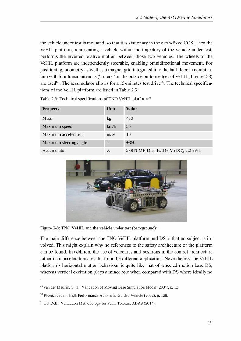
the vehicle under test is mounted, so that it is stationary in the earth-fixed COS. Then the
VeHIL platform, representing a vehicle within the trajectory of the vehicle under test,
performs the inverted relative motion between those two vehicles. The wheels of the
VeHIL platform are independently steerable, enabling omnidirectional movement. For
positioning, odometry as well as a magnet grid integrated into the hall floor in combina-
tion with four linear antennas (“rulers” on the outside bottom edges of VeHIL, Figure 2-8)
are used69. The accumulator allows for a 15-minutes test drive70. The technical specifica-
tions of the VeHIL platform are listed in Table 2.3:
Table 2.3: Technical specifications of TNO VeHIL platform70
Property Unit Value
Mass kg 450
Maximum speed km/h 50
Maximum acceleration m/s² 10
Maximum steering angle ° ±350
Accumulator ./. 288 NiMH D-cells, 346 V (DC), 2.2 kWh
Figure 2-8: TNO VeHIL and the vehicle under test (background)71
The main difference between the TNO VeHIL platform and DS is that no subject is in-
volved. This might explain why no references to the safety architecture of the platform
can be found. In addition, the use of velocities and positions in the control architecture
rather than accelerations results from the different application. Nevertheless, the VeHIL
platform’s horizontal motion behaviour is quite like that of wheeled motion base DS,
whereas vertical excitation plays a minor role when compared with DS where ideally no
69 van der Meulen, S. H.: Validation of Moving Base Simulation Model (2004). p. 13.
70 Ploeg, J. et al.: High Performance Automatic Guided Vehicle (2002). p. 128.
71 TU Delft: Validation Methodology for Fault-Tolerant ADAS (2014).
2 State-of-the-Art and Scientific Research
20
(non-artificial) road excitation must be perceived by the subject. Also, the concept proves
that even accumulator technology from the year 2004 is an adequate energy supply for
wheeled motion platforms.
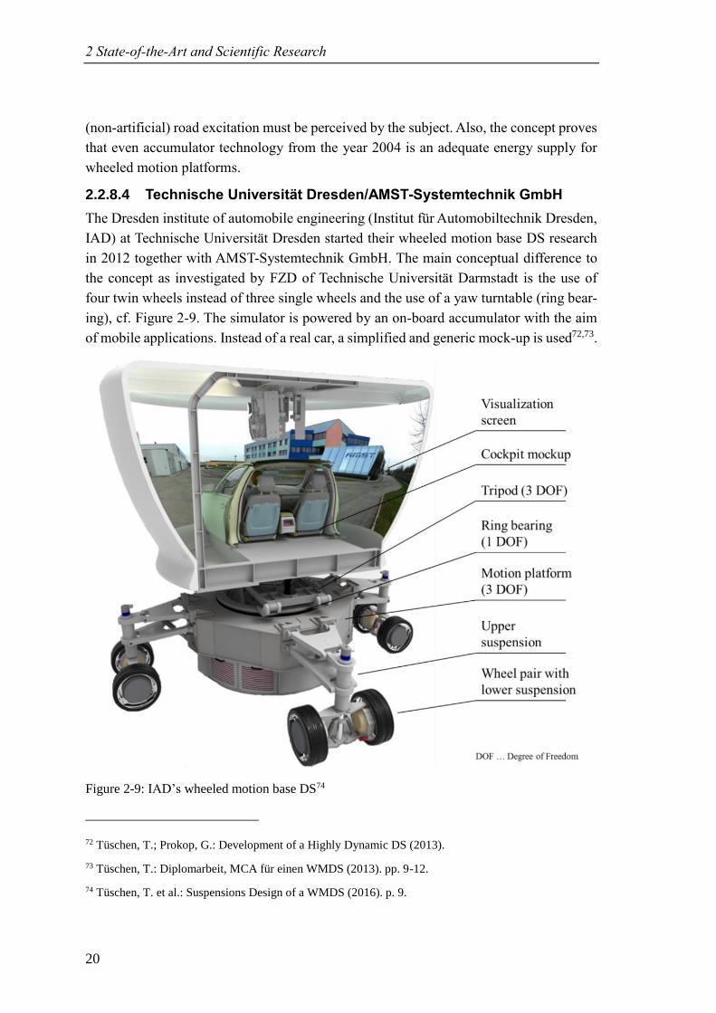
2.2.8.4 Technische Universität Dresden/AMST-Systemtechnik GmbH
The Dresden institute of automobile engineering (Institut für Automobiltechnik Dresden,
IAD) at Technische Universität Dresden started their wheeled motion base DS research
in 2012 together with AMST-Systemtechnik GmbH. The main conceptual difference to
the concept as investigated by FZD of Technische Universität Darmstadt is the use of
four twin wheels instead of three single wheels and the use of a yaw turntable (ring bear-
ing), cf. Figure 2-9. The simulator is powered by an on-board accumulator with the aim
of mobile applications. Instead of a real car, a simplified and generic mock-up is used72,73.
Figure 2-9: IAD’s wheeled motion base DS74
72 Tüschen, T.; Prokop, G.: Development of a Highly Dynamic DS (2013).
73 Tüschen, T.: Diplomarbeit, MCA für einen WMDS (2013). pp. 9-12.
74 Tüschen, T. et al.: Suspensions Design of a WMDS (2016). p. 9.
2.2 State-of-the-Art Driving Simulators
21
The yaw turntable constitutes a redundant DOF because the motion platform itself is also
capable of yawing. To overcome the limitation of the non-holonomic constraint of the
tire, the motion platform is constantly rotating while the dome is counterrotating. Thus,
the subject will not notice the platform’s rotation75a. The idea is that the wheels will never
get into standstill so that lateral forces may be built up anytime. This is important because
– without camber – tires build up lateral forces through generating a slip angle, which on
the other hand means that the wheel needs to have a velocity vector that can be rotated.
Nevertheless, none of Technische Universität Dresden’s publications addresses how to
avoid situations where the superposed rotation of the motion platform is cancelled out by
the primary trajectory of the motion platform that is generated by the MCA. The likeli-
hood of this event happening at one wheel is not negligible but becomes insignificant to
happen for more than one wheel simultaneously76. Still, cancelling out the superposed
rotation can lead to undesired motion cue latency and, therefore, false cues.
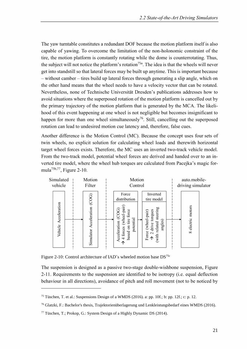
Another difference is the Motion Control (MC). Because the concept uses four sets of
twin wheels, no explicit solution for calculating wheel loads and therewith horizontal
target wheel forces exists. Therefore, the MC uses an inverted two-track vehicle model.
From the two-track model, potential wheel forces are derived and handed over to an in-
verted tire model, where the wheel hub torques are calculated from Pacejka’s magic for-
mula75b,77, Figure 2-10.
Figure 2-10: Control architecture of IAD’s wheeled motion base DS75c
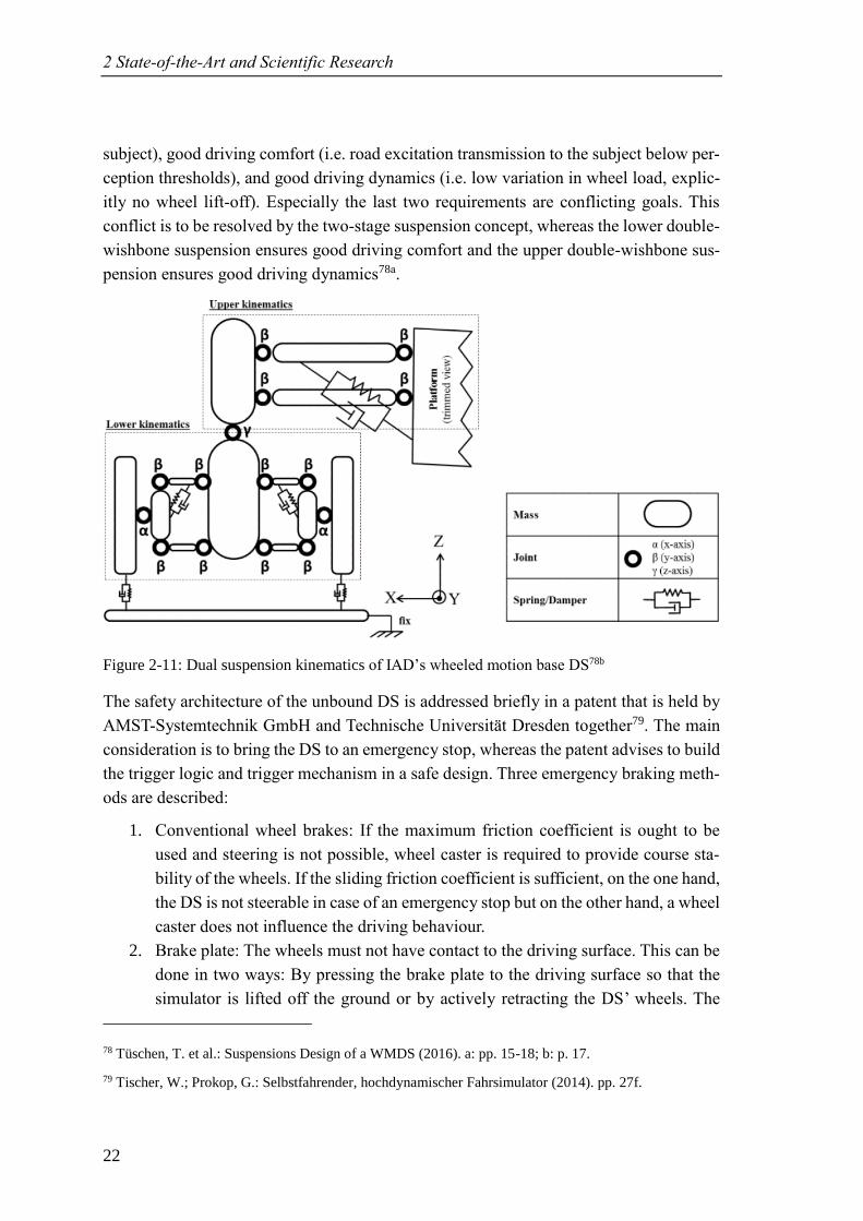
The suspension is designed as a passive two-stage double-wishbone suspension, Figure
2-11. Requirements to the suspension are identified to be isotropy (i.e. equal deflection
behaviour in all directions), avoidance of pitch and roll movement (not to be noticed by
75 Tüschen, T. et al.: Suspensions Design of a WMDS (2016). a: pp. 10f.; b: pp. 12f.; c: p. 12.
76 Glatzki, F.: Bachelor's thesis, Trajektorienüberlagerung und Lenkleistungsbedarf eines WMDS (2016).
77 Tüschen, T.; Prokop, G.: System Design of a Highly Dynamic DS (2014).
2 State-of-the-Art and Scientific Research
22
subject), good driving comfort (i.e. road excitation transmission to the subject below per-
ception thresholds), and good driving dynamics (i.e. low variation in wheel load, explic-
itly no wheel lift-off). Especially the last two requirements are conflicting goals. This
conflict is to be resolved by the two-stage suspension concept, whereas the lower double-
wishbone suspension ensures good driving comfort and the upper double-wishbone sus-
pension ensures good driving dynamics78a.
Figure 2-11: Dual suspension kinematics of IAD’s wheeled motion base DS78b
The safety architecture of the unbound DS is addressed briefly in a patent that is held by
AMST-Systemtechnik GmbH and Technische Universität Dresden together79. The main
consideration is to bring the DS to an emergency stop, whereas the patent advises to build
the trigger logic and trigger mechanism in a safe design. Three emergency braking meth-
ods are described:
1. Conventional wheel brakes: If the maximum friction coefficient is ought to be
used and steering is not possible, wheel caster is required to provide course sta-
bility of the wheels. If the sliding friction coefficient is sufficient, on the one hand,
the DS is not steerable in case of an emergency stop but on the other hand, a wheel
caster does not influence the driving behaviour.
2. Brake plate: The wheels must not have contact to the driving surface. This can be
done in two ways: By pressing the brake plate to the driving surface so that the
simulator is lifted off the ground or by actively retracting the DS’ wheels. The
78 Tüschen, T. et al.: Suspensions Design of a WMDS (2016). a: pp. 15-18; b: p. 17.
79 Tischer, W.; Prokop, G.: Selbstfahrender, hochdynamischer Fahrsimulator (2014). pp. 27f.
2.2 State-of-the-Art Driving Simulators
23
friction coefficient of the brake plate and the driving surface must be designed so
that the DS cannot fall over in an emergency brake situation.
3. Braking bags: One or more inflatable braking bags are inflated in a short time,
making contact to the driving surface and thus generating friction force. This
method may be used alone or in combination with the first and second method.
2.2.8.5 Technische Universität Darmstadt, Department of Control Systems
and Mechatronics
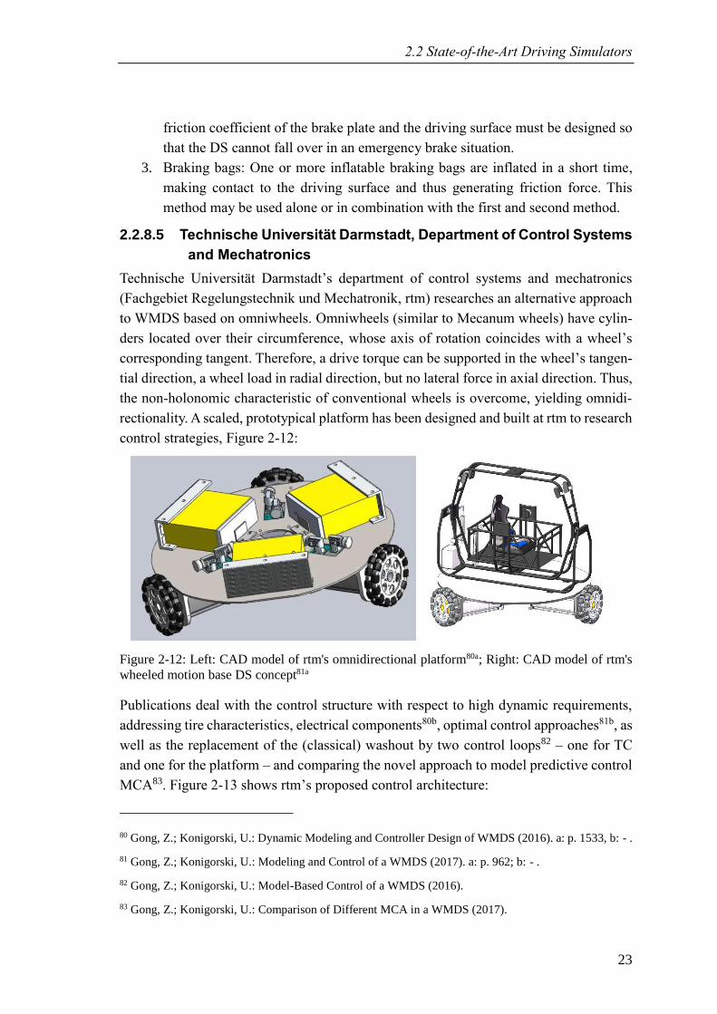
Technische Universität Darmstadt’s department of control systems and mechatronics
(Fachgebiet Regelungstechnik und Mechatronik, rtm) researches an alternative approach
to WMDS based on omniwheels. Omniwheels (similar to Mecanum wheels) have cylin-
ders located over their circumference, whose axis of rotation coincides with a wheel’s
corresponding tangent. Therefore, a drive torque can be supported in the wheel’s tangen-
tial direction, a wheel load in radial direction, but no lateral force in axial direction. Thus,
the non-holonomic characteristic of conventional wheels is overcome, yielding omnidi-
rectionality. A scaled, prototypical platform has been designed and built at rtm to research
control strategies, Figure 2-12:
Figure 2-12: Left: CAD model of rtm's omnidirectional platform80a; Right: CAD model of rtm's
wheeled motion base DS concept81a
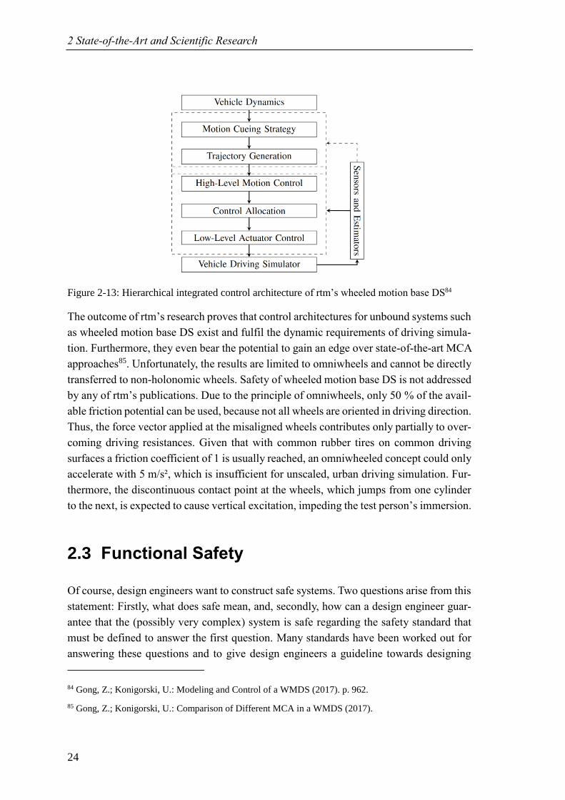
Publications deal with the control structure with respect to high dynamic requirements,
addressing tire characteristics, electrical components80b, optimal control approaches81b, as
well as the replacement of the (classical) washout by two control loops82 – one for TC
and one for the platform – and comparing the novel approach to model predictive control
MCA83. Figure 2-13 shows rtm’s proposed control architecture:
80 Gong, Z.; Konigorski, U.: Dynamic Modeling and Controller Design of WMDS (2016). a: p. 1533, b: - .
81 Gong, Z.; Konigorski, U.: Modeling and Control of a WMDS (2017). a: p. 962; b: - .
82 Gong, Z.; Konigorski, U.: Model-Based Control of a WMDS (2016).
83 Gong, Z.; Konigorski, U.: Comparison of Different MCA in a WMDS (2017).
2 State-of-the-Art and Scientific Research
24
Figure 2-13: Hierarchical integrated control architecture of rtm’s wheeled motion base DS84
The outcome of rtm’s research proves that control architectures for unbound systems such
as wheeled motion base DS exist and fulfil the dynamic requirements of driving simula-
tion. Furthermore, they even bear the potential to gain an edge over state-of-the-art MCA
approaches85. Unfortunately, the results are limited to omniwheels and cannot be directly
transferred to non-holonomic wheels. Safety of wheeled motion base DS is not addressed
by any of rtm’s publications. Due to the principle of omniwheels, only 50 % of the avail-
able friction potential can be used, because not all wheels are oriented in driving direction.
Thus, the force vector applied at the misaligned wheels contributes only partially to over-
coming driving resistances. Given that with common rubber tires on common driving
surfaces a friction coefficient of 1 is usually reached, an omniwheeled concept could only
accelerate with 5 m/s², which is insufficient for unscaled, urban driving simulation. Fur-
thermore, the discontinuous contact point at the wheels, which jumps from one cylinder
to the next, is expected to cause vertical excitation, impeding the test person’s immersion.
2.3 Functional Safety
Of course, design engineers want to construct safe systems. Two questions arise from this
statement: Firstly, what does safe mean, and, secondly, how can a design engineer guar-
antee that the (possibly very complex) system is safe regarding the safety standard that
must be defined to answer the first question. Many standards have been worked out for
answering these questions and to give design engineers a guideline towards designing
84 Gong, Z.; Konigorski, U.: Modeling and Control of a WMDS (2017). p. 962.
85 Gong, Z.; Konigorski, U.: Comparison of Different MCA in a WMDS (2017).
2.3 Functional Safety
25
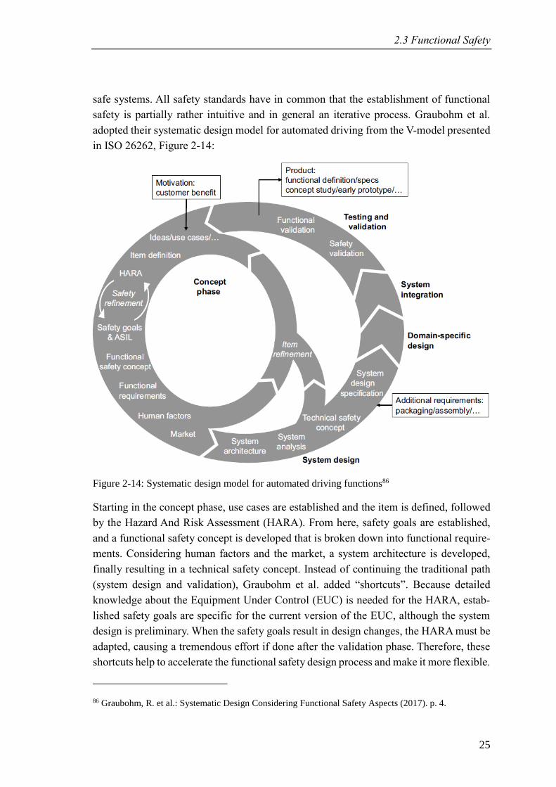
safe systems. All safety standards have in common that the establishment of functional
safety is partially rather intuitive and in general an iterative process. Graubohm et al.
adopted their systematic design model for automated driving from the V-model presented
in ISO 26262, Figure 2-14:
Figure 2-14: Systematic design model for automated driving functions86
Starting in the concept phase, use cases are established and the item is defined, followed
by the Hazard And Risk Assessment (HARA). From here, safety goals are established,
and a functional safety concept is developed that is broken down into functional require-
ments. Considering human factors and the market, a system architecture is developed,
finally resulting in a technical safety concept. Instead of continuing the traditional path
(system design and validation), Graubohm et al. added “shortcuts”. Because detailed
knowledge about the Equipment Under Control (EUC) is needed for the HARA, estab-
lished safety goals are specific for the current version of the EUC, although the system
design is preliminary. When the safety goals result in design changes, the HARA must be
adapted, causing a tremendous effort if done after the validation phase. Therefore, these
shortcuts help to accelerate the functional safety design process and make it more flexible.
86 Graubohm, R. et al.: Systematic Design Considering Functional Safety Aspects (2017). p. 4.
2 State-of-the-Art and Scientific Research
26
Concluding, three axioms can be postulated for the design of functional safety:
1. Hazard identification is rather intuitive.
2. The design of functional safety is iterative.
3. A preliminary system design and understanding is needed for performing the
HARA, although the goal of the process is to design a safe system based on the
safety goals established from the HARA.
In the following, the most important functional safety standards with focus on the
IEC 61508 will be described, preceded by the basic terminology that is needed for under-
standing the risk assessment process.
2.3.1 Terminology87
Consequence The consequences and order of events triggered by an initiating failure
Controllability Ability to avoid a specified harm or damage through the timely reac-
tions of the persons involved, possibly with support from external
measures
Element A system or part of a system including components, hardware, software,
hardware parts, and software units
Exposure State of being in an operational situation that can be hazardous if coin-
cident with the failure mode under analysis
Failure Termination of an element to perform a function as required
Fault Abnormal condition that can cause an element to fail
Functional safety Absence of unreasonable risk due to hazards caused by malfunctioning
behaviour of Electrical/Electronic/Programmable Electronic (E/E/PE)
safety-related systems
Harm Physical injury or damage to the health of persons
Hazard Potential source of harm caused by malfunctioning behaviour of an el-
ement (combination of failure and its consequence)
Hazardous event Combination of a hazard and a critical operational situation
Risk Combination of the probability of a harm’s occurrence and its severity
Safety function A function, which is intended to achieve or maintain a safe state for the
EUC, in respect of a specific hazardous event (cf. safety goal)
87 Cf. ISO TC 22/SC 32 Electrical and electronic components and general system aspects: ISO 26262
(2011).
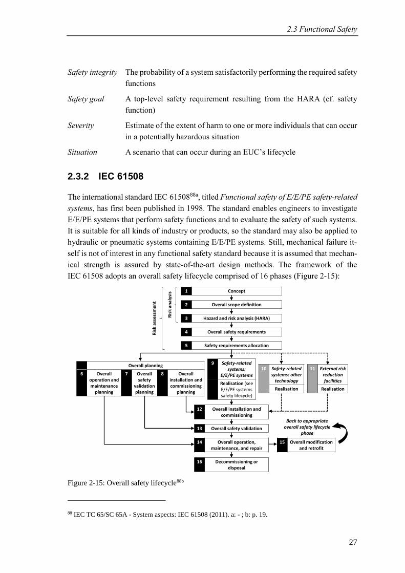
2.3 Functional Safety
27
Safety integrity The probability of a system satisfactorily performing the required safety
functions
Safety goal A top-level safety requirement resulting from the HARA (cf. safety
function)
Severity Estimate of the extent of harm to one or more individuals that can occur
in a potentially hazardous situation
Situation A scenario that can occur during an EUC’s lifecycle
2.3.2 IEC 61508
The international standard IEC 6150888a, titled Functional safety of E/E/PE safety-related
systems, has first been published in 1998. The standard enables engineers to investigate
E/E/PE systems that perform safety functions and to evaluate the safety of such systems.
It is suitable for all kinds of industry or products, so the standard may also be applied to
hydraulic or pneumatic systems containing E/E/PE systems. Still, mechanical failure it-
self is not of interest in any functional safety standard because it is assumed that mechan-
ical strength is assured by state-of-the-art design methods. The framework of the
IEC 61508 adopts an overall safety lifecycle comprised of 16 phases (Figure 2-15):
Figure 2-15: Overall safety lifecycle88b
88 IEC TC 65/SC 65A - System aspects: IEC 61508 (2011). a: - ; b: p. 19.
1 Concept
2 Overall scope definition
3 Hazard and risk analysis (HARA)
4 Overall safety requirements
5 Safety requirements allocation
9 Safety-related systems:
E/E/PE systems
Realisation (see E/E/PE systems safety lifecycle)
10 Safety-related systems: other
technology
Realisation
11 External risk reduction facilities
Realisation
Overall planning
6 Overall operation and maintenance
planning
7 Overall safety
validation planning
8 Overall installation and commissioning
planning
12 Overall installation and commissioning
13 Overall safety validation
14 Overall operation, maintenance, and repair
15 Overall modification and retrofit
16 Decommissioning or disposal
Back to appropriate overall safety lifecycle
phase
Ris
k an
alys
is
Ris
k as
sess
me
nt
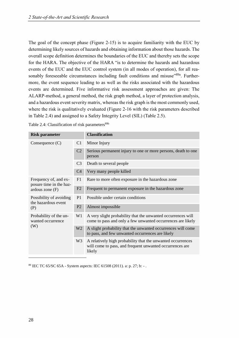
2 State-of-the-Art and Scientific Research
28
The goal of the concept phase (Figure 2-15) is to acquire familiarity with the EUC by
determining likely sources of hazards and obtaining information about those hazards. The
overall scope definition determines the boundaries of the EUC and thereby sets the scope
for the HARA. The objective of the HARA “is to determine the hazards and hazardous
events of the EUC and the EUC control system (in all modes of operation), for all rea-
sonably foreseeable circumstances including fault conditions and misuse”89a. Further-
more, the event sequence leading to as well as the risks associated with the hazardous
events are determined. Five informative risk assessment approaches are given: The
ALARP-method, a general method, the risk graph method, a layer of protection analysis,
and a hazardous event severity matrix, whereas the risk graph is the most commonly used,
where the risk is qualitatively evaluated (Figure 2-16 with the risk parameters described
in Table 2.4) and assigned to a Safety Integrity Level (SIL) (Table 2.5).
Table 2.4: Classification of risk parameters89b
Risk parameter Classification
Consequence (C) C1 Minor Injury
C2 Serious permanent injury to one or more persons, death to one
person
C3 Death to several people
C4 Very many people killed
Frequency of, and ex-
posure time in the haz-
ardous zone (F)
F1 Rare to more often exposure in the hazardous zone
F2 Frequent to permanent exposure in the hazardous zone
Possibility of avoiding
the hazardous event
(P)
P1 Possible under certain conditions
P2 Almost impossible
Probability of the un-
wanted occurrence
(W)
W1 A very slight probability that the unwanted occurrences will
come to pass and only a few unwanted occurrences are likely
W2 A slight probability that the unwanted occurrences will come
to pass, and few unwanted occurrences are likely
W3 A relatively high probability that the unwanted occurrences
will come to pass, and frequent unwanted occurrences are
likely
89 IEC TC 65/SC 65A - System aspects: IEC 61508 (2011). a: p. 27; b: - .
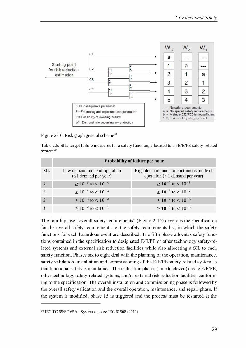
2.3 Functional Safety
29
Figure 2-16: Risk graph general scheme90
Table 2.5: SIL: target failure measures for a safety function, allocated to an E/E/PE safety-related
system90
Probability of failure per hour
SIL Low demand mode of operation
(≤1 demand per year)
High demand mode or continuous mode of
operation (> 1 demand per year)
4 ≥ 10−5 to < 10−4 ≥ 10−9 to < 10−8
3 ≥ 10−4 to < 10−3 ≥ 10−8 to < 10−7
2 ≥ 10−3 to < 10−2 ≥ 10−7 to < 10−6
1 ≥ 10−2 to < 10−1 ≥ 10−6 to < 10−5
The fourth phase “overall safety requirements” (Figure 2-15) develops the specification
for the overall safety requirement, i.e. the safety requirements list, in which the safety
functions for each hazardous event are described. The fifth phase allocates safety func-
tions contained in the specification to designated E/E/PE or other technology safety-re-
lated systems and external risk reduction facilities while also allocating a SIL to each
safety function. Phases six to eight deal with the planning of the operation, maintenance,
safety validation, installation and commissioning of the E/E/PE safety-related system so
that functional safety is maintained. The realisation phases (nine to eleven) create E/E/PE,
other technology safety-related systems, and/or external risk reduction facilities conform-
ing to the specification. The overall installation and commissioning phase is followed by
the overall safety validation and the overall operation, maintenance, and repair phase. If
the system is modified, phase 15 is triggered and the process must be restarted at the
90 IEC TC 65/SC 65A - System aspects: IEC 61508 (2011).
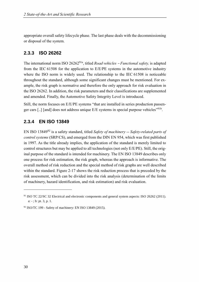
2 State-of-the-Art and Scientific Research
30
appropriate overall safety lifecycle phase. The last phase deals with the decommissioning
or disposal of the system.
2.3.3 ISO 26262
The international norm ISO 2626291a, titled Road vehicles – Functional safety, is adapted
from the IEC 61508 for the application to E/E/PE systems in the automotive industry
where the ISO norm is widely used. The relationship to the IEC 61508 is noticeable
throughout the standard, although some significant changes must be mentioned. For ex-
ample, the risk graph is normative and therefore the only approach for risk evaluation in
the ISO 26262. In addition, the risk parameters and their classifications are supplemented
and amended. Finally, the Automotive Safety Integrity Level is introduced.
Still, the norm focuses on E/E/PE systems “that are installed in series production passen-
ger cars [..] [and] does not address unique E/E systems in special purpose vehicles”91b.
2.3.4 EN ISO 13849
EN ISO 1384992 is a safety standard, titled Safety of machinery -- Safety-related parts of
control systems (SRP/CS), and emerged from the DIN EN 954, which was first published
in 1997. As the title already implies, the application of the standard is merely limited to
control structures but may be applied to all technologies (not only E/E/PE). Still, the orig-
inal purpose of the standard is intended for machinery. The EN ISO 13849 describes only
one process for risk estimation, the risk graph, whereas the approach is informative. The
overall method of risk reduction and the special method of risk graphs are well described
within the standard. Figure 2-17 shows the risk reduction process that is preceded by the
risk assessment, which can be divided into the risk analysis (determination of the limits
of machinery, hazard identification, and risk estimation) and risk evaluation.
91 ISO TC 22/SC 32 Electrical and electronic components and general system aspects: ISO 26262 (2011).
a: - ; b: pt. 3, p. 1.
92 ISO/TC 199 - Safety of machinery: EN ISO 13849 (2015).
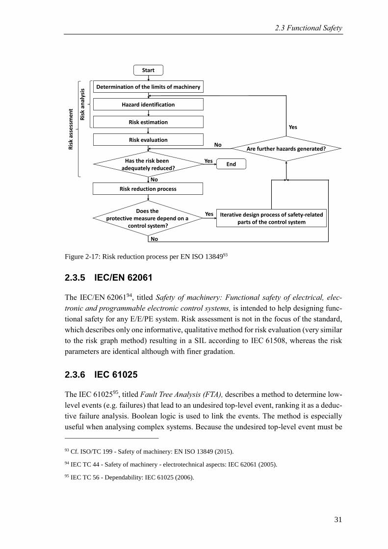
2.3 Functional Safety
31
Figure 2-17: Risk reduction process per EN ISO 1384993
2.3.5 IEC/EN 62061
The IEC/EN 6206194, titled Safety of machinery: Functional safety of electrical, elec-
tronic and programmable electronic control systems, is intended to help designing func-
tional safety for any E/E/PE system. Risk assessment is not in the focus of the standard,
which describes only one informative, qualitative method for risk evaluation (very similar
to the risk graph method) resulting in a SIL according to IEC 61508, whereas the risk
parameters are identical although with finer gradation.
2.3.6 IEC 61025
The IEC 6102595, titled Fault Tree Analysis (FTA), describes a method to determine low-
level events (e.g. failures) that lead to an undesired top-level event, ranking it as a deduc-
tive failure analysis. Boolean logic is used to link the events. The method is especially
useful when analysing complex systems. Because the undesired top-level event must be
93 Cf. ISO/TC 199 - Safety of machinery: EN ISO 13849 (2015).
94 IEC TC 44 - Safety of machinery - electrotechnical aspects: IEC 62061 (2005).
95 IEC TC 56 - Dependability: IEC 61025 (2006).
Start
Determination of the limits of machinery
Risk evaluation
Risk estimation
Risk reduction process
Hazard identification
Has the risk been adequately reduced?
Does the protective measure depend on a
control system?
End
No
Yes
Iterative design process of safety-related parts of the control system
Yes
Are further hazards generated?
Yes
No
No
Ris
k an
alys
is
Ris
k as
sess
me
nt
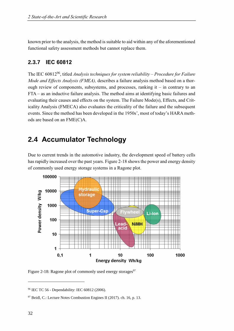
2 State-of-the-Art and Scientific Research
32
known prior to the analysis, the method is suitable to aid within any of the aforementioned
functional safety assessment methods but cannot replace them.
2.3.7 IEC 60812
The IEC 6081296, titled Analysis techniques for system reliability – Procedure for Failure
Mode and Effects Analysis (FMEA), describes a failure analysis method based on a thor-
ough review of components, subsystems, and processes, ranking it – in contrary to an
FTA – as an inductive failure analysis. The method aims at identifying basic failures and
evaluating their causes and effects on the system. The Failure Mode(s), Effects, and Crit-
icality Analysis (FMECA) also evaluates the criticality of the failure and the subsequent
events. Since the method has been developed in the 1950s’, most of today’s HARA meth-
ods are based on an FME(C)A.
2.4 Accumulator Technology
Due to current trends in the automotive industry, the development speed of battery cells
has rapidly increased over the past years. Figure 2-18 shows the power and energy density
of commonly used energy storage systems in a Ragone plot.
Figure 2-18: Ragone plot of commonly used energy storages97
96 IEC TC 56 - Dependability: IEC 60812 (2006).
97 Beidl, C.: Lecture Notes Combustion Engines II (2017). ch. 16, p. 13.
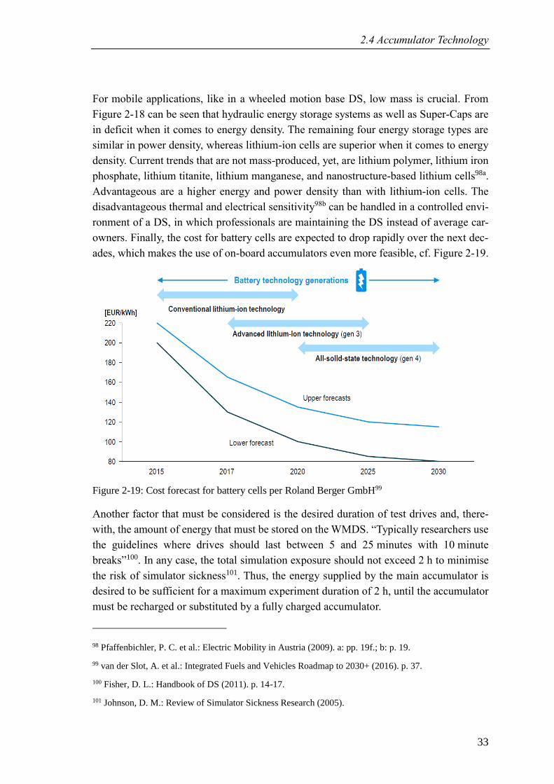
2.4 Accumulator Technology
33
For mobile applications, like in a wheeled motion base DS, low mass is crucial. From
Figure 2-18 can be seen that hydraulic energy storage systems as well as Super-Caps are
in deficit when it comes to energy density. The remaining four energy storage types are
similar in power density, whereas lithium-ion cells are superior when it comes to energy
density. Current trends that are not mass-produced, yet, are lithium polymer, lithium iron
phosphate, lithium titanite, lithium manganese, and nanostructure-based lithium cells98a.
Advantageous are a higher energy and power density than with lithium-ion cells. The
disadvantageous thermal and electrical sensitivity98b can be handled in a controlled envi-
ronment of a DS, in which professionals are maintaining the DS instead of average car-
owners. Finally, the cost for battery cells are expected to drop rapidly over the next dec-
ades, which makes the use of on-board accumulators even more feasible, cf. Figure 2-19.
Figure 2-19: Cost forecast for battery cells per Roland Berger GmbH99
Another factor that must be considered is the desired duration of test drives and, there-
with, the amount of energy that must be stored on the WMDS. “Typically researchers use
the guidelines where drives should last between 5 and 25 minutes with 10 minute
breaks”100. In any case, the total simulation exposure should not exceed 2 h to minimise
the risk of simulator sickness101. Thus, the energy supplied by the main accumulator is
desired to be sufficient for a maximum experiment duration of 2 h, until the accumulator
must be recharged or substituted by a fully charged accumulator.
98 Pfaffenbichler, P. C. et al.: Electric Mobility in Austria (2009). a: pp. 19f.; b: p. 19.
99 van der Slot, A. et al.: Integrated Fuels and Vehicles Roadmap to 2030+ (2016). p. 37.
100 Fisher, D. L.: Handbook of DS (2011). p. 14-17.
101 Johnson, D. M.: Review of Simulator Sickness Research (2005).
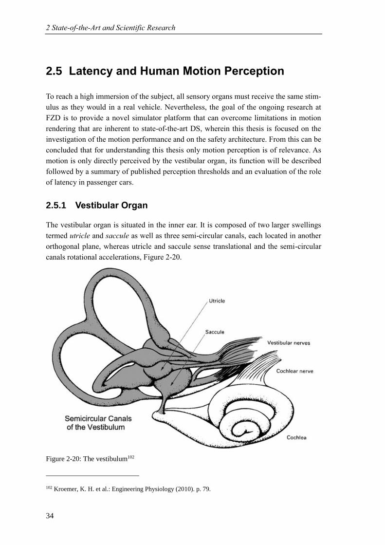
2 State-of-the-Art and Scientific Research
34
2.5 Latency and Human Motion Perception
To reach a high immersion of the subject, all sensory organs must receive the same stim-
ulus as they would in a real vehicle. Nevertheless, the goal of the ongoing research at
FZD is to provide a novel simulator platform that can overcome limitations in motion
rendering that are inherent to state-of-the-art DS, wherein this thesis is focused on the
investigation of the motion performance and on the safety architecture. From this can be
concluded that for understanding this thesis only motion perception is of relevance. As
motion is only directly perceived by the vestibular organ, its function will be described
followed by a summary of published perception thresholds and an evaluation of the role
of latency in passenger cars.
2.5.1 Vestibular Organ
The vestibular organ is situated in the inner ear. It is composed of two larger swellings
termed utricle and saccule as well as three semi-circular canals, each located in another
orthogonal plane, whereas utricle and saccule sense translational and the semi-circular
canals rotational accelerations, Figure 2-20.
Figure 2-20: The vestibulum102
102 Kroemer, K. H. et al.: Engineering Physiology (2010). p. 79.
2.5 Latency and Human Motion Perception
35
Utricle and saccule are perpendicular and contain a region called macula. The macula is
composed of a gelatinous layer, in which sensory hair cells are embedded, topped by a
layer of calcium containing deposits called statoconia or otoliths. The macula of utricle
is oriented horizontally, the macula of saccule vertically. The inertia of the statoconia
causes the sensory hair cells to bend when the head is accelerated, thus sensing accelera-
tion103.
Rotational motion is sensed by the cristae ampullares that are located in each semi-cir-
cular canal, perpendicular to the canals’ walls. The cristae ampullares are composed –
similarly to the maculae – of a gelatinous mass, the cupula, in which sensory hair cells
are embedded. When the head is rotating, the endolymph fluid in the semi-circular canals
is flowing, causing the cristae ampullares and the embedded sensory hair cells to bend,
thus, sensing rotational velocity103.
2.5.2 Human Motion Perception Thresholds
The definition of static perception thresholds is a strenuous task, as already demonstrated
by Fischer104 and Betz105. This is due to manifold influencing factors104, such as:
• Duration of exposure
• Subject’s expectations
• Subject’s physical condition
• Individual sensitivity
• Distraction
• Information from other sensory organs
For the sake of consistency and comparability, the same perception thresholds are used
within this thesis as they were used by Betz105, namely:
• Maximum tilt angle: 24° ≜ 0.4 𝑔
• Rotational velocity threshold: 6 °/s
• Rotational acceleration threshold: 6 °/s2
• Translational acceleration threshold: 0.2 m/s²
103 Csillag, A.: Atlas of the Sensory Organs (2005). pp. 10f.
104 Fischer, M.: Diss., MCA für eine realitätsnahe Bewegungssimulation (2009). p. 14.
105 Betz, A.: Diss., Feasibility Analysis and Design of WMDS (2015). pp. 14ff.
2 State-of-the-Art and Scientific Research
36
2.5.3 Latency
Two thresholds are defined for latency in the motion system: An upper limit and a lower
limit. Obviously, the upper limit is defined by the motion latency that can be felt in a real
car, which is found to be 135 ms for longitudinal and 100 ms for lateral motion; a DS
must stay below those values (section 2.5.3.2). However, there is also a lower limit be-
cause motion cues must not be provided prior to the corresponding visual cue, being
60 ms (section 2.5.3.1). While the upper limit is crucial to fulfil, the lower limit could
also be reached by adding artificial latency in the control structure.
2.5.3.1 Visual Cues
Two types of visual representation systems are considered: Conventional display/video
projector technology and head-mounted displays. For conventional display/video tech-
nology, latency refers to the time span from the user input via HMI to displaying visual
changes resulting from the input. For HMDs, latency also refers to the time span from the
user’s head movement to displaying visual changes resulting from the head movement.
Literature reports that the detection of the driver’s head movement may be reduced to less
than 10 ms if optical sensors are combined with a gyro. Still, the traffic simulation needs
about 50 ms for presenting the head movement in the virtual reality106. Another study
showed that latencies above 267 ms are perceptible to most participants107. Thus, the la-
tency in the motion system is desired to be within the range of 60 ms to 267 ms (lower
motion latency bears no advantage since the calculation of the visual stimulus takes at
least 60 ms and the motion cue must not be represented prior to the visual cue).
2.5.3.2 Acceleration Cues
The control inputs are given by the driver – in the real vehicle as well as in the DS. Thus,
latency in the motion system is defined as the time span from the driver’s acceleration
demand (by brake pedal, acceleration pedal, steering wheel, etc.) to the actual presenta-
tion of the demanded acceleration. A DS’ delay in acceleration representation is regarded
to be sufficiently low if the values are below those of a real car and will be referred to as
Acceleration Cue Latency (ACL). In any case (lateral or longitudinal motion), the time
needed for calculating the control inputs in the MCA and MC must be accounted for.
Also, if a physics-based vehicle model is used, inherent latencies, e.g. when using an
elaborate tire model that takes relaxation lengths etc. into account, must not add to ACL.
Thus, a latency model might be needed in the MC, resembling a feed forward control.
Whereas the latter issue addresses the control and is therefore not dealt with in this thesis,
106 Berg, G.; Färber, B.: Vehicle in the Loop (2015). pp. 160f.
107 Wildzunas, R. M. et al.: Visual Display Delay Effects on Pilot Performance (1996). per St. Pierre, M. E.
et al.: The Effects of Latency on Simulator Sickness in a HMD (2015). p. 1.
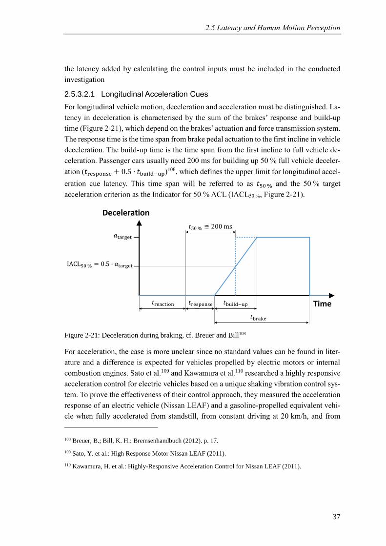
2.5 Latency and Human Motion Perception
37
the latency added by calculating the control inputs must be included in the conducted
investigation
2.5.3.2.1 Longitudinal Acceleration Cues
For longitudinal vehicle motion, deceleration and acceleration must be distinguished. La-
tency in deceleration is characterised by the sum of the brakes’ response and build-up
time (Figure 2-21), which depend on the brakes’ actuation and force transmission system.
The response time is the time span from brake pedal actuation to the first incline in vehicle
deceleration. The build-up time is the time span from the first incline to full vehicle de-
celeration. Passenger cars usually need 200 ms for building up 50 % full vehicle deceler-
ation (𝑡response + 0.5 ∙ 𝑡build−up)108, which defines the upper limit for longitudinal accel-
eration cue latency. This time span will be referred to as 𝑡50 % and the 50 % target
acceleration criterion as the Indicator for 50 % ACL (IACL50 %, Figure 2-21).
Figure 2-21: Deceleration during braking, cf. Breuer and Bill108
For acceleration, the case is more unclear since no standard values can be found in liter-
ature and a difference is expected for vehicles propelled by electric motors or internal
combustion engines. Sato et al.109 and Kawamura et al.110 researched a highly responsive
acceleration control for electric vehicles based on a unique shaking vibration control sys-
tem. To prove the effectiveness of their control approach, they measured the acceleration
response of an electric vehicle (Nissan LEAF) and a gasoline-propelled equivalent vehi-
cle when fully accelerated from standstill, from constant driving at 20 km/h, and from
108 Breuer, B.; Bill, K. H.: Bremsenhandbuch (2012). p. 17.
109 Sato, Y. et al.: High Response Motor Nissan LEAF (2011).
110 Kawamura, H. et al.: Highly-Responsive Acceleration Control for Nissan LEAF (2011).
Time
Deceleration
𝑎tar et
𝑡rea tion 𝑡response 𝑡build−up
𝑡bra e
𝑡50 % 200 ms
50 % = 0.5 𝑎tar et
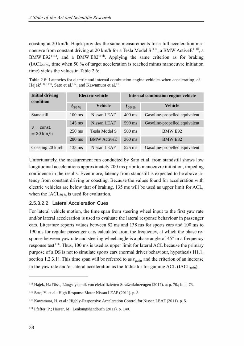
2 State-of-the-Art and Scientific Research
38
coasting at 20 km/h. Hajek provides the same measurements for a full acceleration ma-
noeuvre from constant driving at 20 km/h for a Tesla Model S111a, a BMW ActiveE111b, a
BMW E92111a, and a BMW E82111b. Applying the same criterion as for braking
(IACL50 %, time when 50 % of target acceleration is reached minus manoeuvre initiation
time) yields the values in Table 2.6:
Table 2.6: Latencies for electric and internal combustion engine vehicles when accelerating, cf.
Hajek111a,111b, Sato et al.112, and Kawamura et al.113
Initial driving
condition
Electric vehicle Internal combustion engine vehicle
𝒕𝟓𝟎 % Vehicle 𝒕𝟓𝟎 % Vehicle
Standstill 100 ms Nissan LEAF 400 ms Gasoline-propelled equivalent
𝑣 = const.
= 20 km/h
145 ms Nissan LEAF 590 ms Gasoline-propelled equivalent
250 ms Tesla Model S 500 ms BMW E92
280 ms BMW ActiveE 360 ms BMW E82
Coasting 20 km/h 135 ms Nissan LEAF 525 ms Gasoline-propelled equivalent
Unfortunately, the measurement run conducted by Sato et al. from standstill shows low
longitudinal accelerations approximately 200 ms prior to manoeuvre initiation, impeding
confidence in the results. Even more, latency from standstill is expected to be above la-
tency from constant driving or coasting. Because the values found for acceleration with
electric vehicles are below that of braking, 135 ms will be used as upper limit for ACL,
when the IACL50 % is used for evaluation.
2.5.3.2.2 Lateral Acceleration Cues
For lateral vehicle motion, the time span from steering wheel input to the first yaw rate
and/or lateral acceleration is used to evaluate the lateral response behaviour in passenger
cars. Literature reports values between 82 ms and 138 ms for sports cars and 100 ms to
190 ms for regular passenger cars calculated from the frequency, at which the phase re-
sponse between yaw rate and steering wheel angle is a phase angle of 45° in a frequency
response test114. Thus, 100 ms is used as upper limit for lateral ACL because the primary
purpose of a DS is not to simulate sports cars (normal driver behaviour, hypothesis H1.1,
section 1.2.3.1). This time span will be referred to as 𝑡 ain and the criterion of an increase
in the yaw rate and/or lateral acceleration as the Indicator for gaining ACL (IACLgain).
111 Hajek, H.: Diss., Längsdynamik von elektrifizierten Straßenfahrzeugen (2017). a: p. 70.; b: p. 73.
112 Sato, Y. et al.: High Response Motor Nissan LEAF (2011). p. 8.
113 Kawamura, H. et al.: Highly-Responsive Acceleration Control for Nissan LEAF (2011). p. 5.
114 Pfeffer, P.; Harrer, M.: Lenkungshandbuch (2011). p. 140.
39
3 Wheeled Mobile Driving Simulator Proto-type MORPHEUS
The basic concept behind a wheeled motion base DS has been explained in section 2.2.6.
At FZD, a scaled prototype of a wheeled mobile driving simulator (WMDS) has been
designed and manufactured for investigating the feasibility of the concept. The prototype
is called MORPHEUS, which is the acronym for Mobile OmnidiRectional Platform for
Highly dynamic and tirEboUnd driving Simulation. This chapter describes MORPHEUS
and its architecture so that the reader is enabled to follow the outline of the falsification
experiments for the wheeled motion base and the design of the safety architecture.
3.1 FZD’s WMDS Concept
The concept idea has been developed by Betz et al.115. The core element of FZD’s WMDS
concept is an omnidirectional platform standing on three self-propelled and actively and
infinitely steerable wheel units. Thus, the linkage between motion range and system mass
is dissolved and, additionally, an infinite yaw DOF is created, improving urban driving
simulation capabilities. The tilt system (for TC) in this concept can be reduced to
three DOF, namely pitch, roll, and heave. A tripod is sufficient for providing these DOF.
3.2 MORPHEUS’ Design
However, in the concept design for MORPHEUS decisions were made regarding require-
ments like sufficient system dynamics for urban driving simulation and safety, but also
costs, ease of manufacturing, and/or availability of purchased parts. Thus, a hexapod was
chosen over a tripod, because the range of available hexapods is larger than that of tripods
and the additional DOF can be advantageous. E.g. missing or false cues from vertical
excitation due to uneven road surface or from misaligned wheels can be masked116. A
detailed description of MORPHEUS’ development can be found in Wagner et al.117.
115 Betz, A. et al.: Concept Analysis of a WMDS (2012).
116 Wagner, P. et al.: Potentials and Limitations of Hexapods in WMDS (2015).
117 Wagner, P. et al.: Conception and Design of Mobile Driving Simulators (2014).
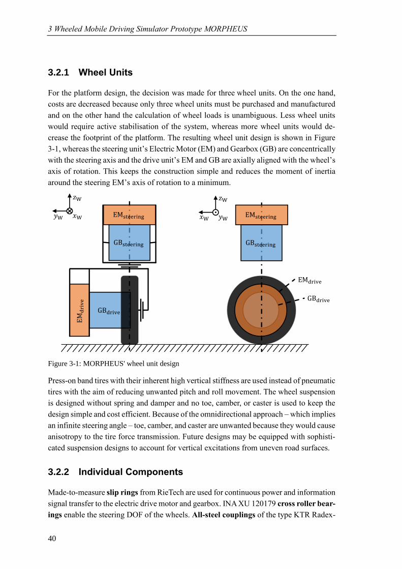
3 Wheeled Mobile Driving Simulator Prototype MORPHEUS
40
3.2.1 Wheel Units
For the platform design, the decision was made for three wheel units. On the one hand,
costs are decreased because only three wheel units must be purchased and manufactured
and on the other hand the calculation of wheel loads is unambiguous. Less wheel units
would require active stabilisation of the system, whereas more wheel units would de-
crease the footprint of the platform. The resulting wheel unit design is shown in Figure
3-1, whereas the steering unit’s Electric Motor (EM) and Gearbox (GB) are concentrically
with the steering axis and the drive unit’s EM and GB are axially aligned with the wheel’s
axis of rotation. This keeps the construction simple and reduces the moment of inertia
around the steering EM’s axis of rotation to a minimum.
Figure 3-1: MORPHEUS' wheel unit design
Press-on band tires with their inherent high vertical stiffness are used instead of pneumatic
tires with the aim of reducing unwanted pitch and roll movement. The wheel suspension
is designed without spring and damper and no toe, camber, or caster is used to keep the
design simple and cost efficient. Because of the omnidirectional approach – which implies
an infinite steering angle – toe, camber, and caster are unwanted because they would cause
anisotropy to the tire force transmission. Future designs may be equipped with sophisti-
cated suspension designs to account for vertical excitations from uneven road surfaces.
3.2.2 Individual Components
Made-to-measure slip rings from RieTech are used for continuous power and information
signal transfer to the electric drive motor and gearbox. INA XU 120179 cross roller bear-
ings enable the steering DOF of the wheels. All-steel couplings of the type KTR Radex-
steerin
dri e
steerin
dri e
𝑥 𝑦
𝑧
steerin
steerin
dri e
dri e
𝑥 𝑦
𝑧
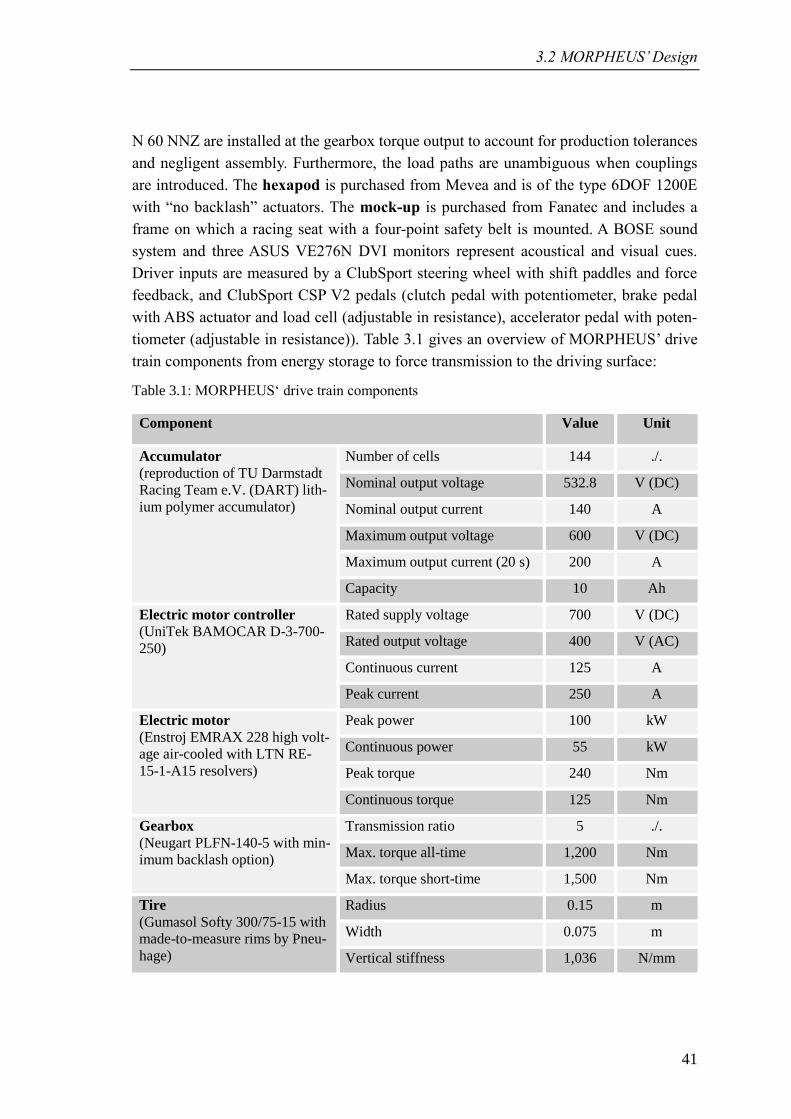
3.2 MORPHEUS’ Design
41
N 60 NNZ are installed at the gearbox torque output to account for production tolerances
and negligent assembly. Furthermore, the load paths are unambiguous when couplings
are introduced. The hexapod is purchased from Mevea and is of the type 6DOF 1200E
with “no backlash” actuators. The mock-up is purchased from Fanatec and includes a
frame on which a racing seat with a four-point safety belt is mounted. A BOSE sound
system and three ASUS VE276N DVI monitors represent acoustical and visual cues.
Driver inputs are measured by a ClubSport steering wheel with shift paddles and force
feedback, and ClubSport CSP V2 pedals (clutch pedal with potentiometer, brake pedal
with ABS actuator and load cell (adjustable in resistance), accelerator pedal with poten-
tiometer (adjustable in resistance)). Table 3.1 gives an overview of MORPHEUS’ drive
train components from energy storage to force transmission to the driving surface:
Table 3.1: MORPHEUS‘ drive train components
Component Value Unit
Accumulator
(reproduction of TU Darmstadt
Racing Team e.V. (DART) lith-
ium polymer accumulator)
Number of cells 144 ./.
Nominal output voltage 532.8 V (DC)
Nominal output current 140 A
Maximum output voltage 600 V (DC)
Maximum output current (20 s) 200 A
Capacity 10 Ah
Electric motor controller
(UniTek BAMOCAR D-3-700-
250)
Rated supply voltage 700 V (DC)
Rated output voltage 400 V (AC)
Continuous current 125 A
Peak current 250 A
Electric motor
(Enstroj EMRAX 228 high volt-
age air-cooled with LTN RE-
15-1-A15 resolvers)
Peak power 100 kW
Continuous power 55 kW
Peak torque 240 Nm
Continuous torque 125 Nm
Gearbox
(Neugart PLFN-140-5 with min-
imum backlash option)
Transmission ratio 5 ./.
Max. torque all-time 1,200 Nm
Max. torque short-time 1,500 Nm
Tire
(Gumasol Softy 300/75-15 with
made-to-measure rims by Pneu-
hage)
Radius 0.15 m
Width 0.075 m
Vertical stiffness 1,036 N/mm
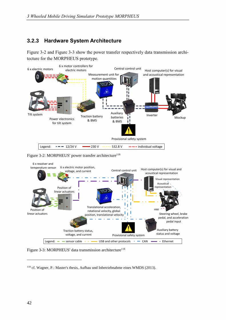
3 Wheeled Mobile Driving Simulator Prototype MORPHEUS
42
3.2.3 Hardware System Architecture
Figure 3-2 and Figure 3-3 show the power transfer respectively data transmission archi-
tecture for the MORPHEUS prototype.
Figure 3-2: MORPHEUS' power transfer architecture118
Figure 3-3: MORPHEUS' data transmission architecture118
118 cf. Wagner, P.: Master's thesis, Aufbau und Inbetriebnahme eines WMDS (2013).
Traction battery & BMS
6 x electric motors6 x motor controllers for
electric motors
Tilt system
Power electronics for tilt system
Auxiliary batteries& BMS
Central control unit
InverterMockup
Legend: 12/24 V 230 V 532.8 V individual voltage
Provisional safety system
Host computer(s) for visualand acoustical representationMeasurement unit for
motion quantities
HMI
Visual representation
Acoustical representation
6 x resolver and temperature sensor 6 x electric motor position,
voltage, and current
Position oflinear actuators
Position oflinear actuators
Traction battery status, voltage, and current
Central control unit Host computer(s) for visual and acoustical representation
Provisional safety system
Auxiliary battery status and voltage
Legend: sensor cable USB and other protocols CAN Ethernet
Translational acceleration,rotational velocity, global
position, translational velocity Steering wheel, brake pedal, and acceleration
pedal input
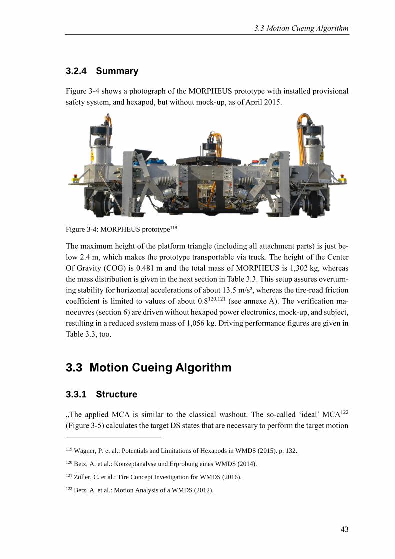
3.3 Motion Cueing Algorithm
43
3.2.4 Summary
Figure 3-4 shows a photograph of the MORPHEUS prototype with installed provisional
safety system, and hexapod, but without mock-up, as of April 2015.
Figure 3-4: MORPHEUS prototype119
The maximum height of the platform triangle (including all attachment parts) is just be-
low 2.4 m, which makes the prototype transportable via truck. The height of the Center
Of Gravity (COG) is 0.481 m and the total mass of MORPHEUS is 1,302 kg, whereas
the mass distribution is given in the next section in Table 3.3. This setup assures overturn-
ing stability for horizontal accelerations of about 13.5 m/s², whereas the tire-road friction
coefficient is limited to values of about 0.8120,121 (see annexe A). The verification ma-
noeuvres (section 6) are driven without hexapod power electronics, mock-up, and subject,
resulting in a reduced system mass of 1,056 kg. Driving performance figures are given in
Table 3.3, too.
3.3 Motion Cueing Algorithm
3.3.1 Structure
„The applied MCA is similar to the classical washout. The so-called ‘ideal’ MCA122
(Figure 3-5) calculates the target DS states that are necessary to perform the target motion
119 Wagner, P. et al.: Potentials and Limitations of Hexapods in WMDS (2015). p. 132.
120 Betz, A. et al.: Konzeptanalyse und Erprobung eines WMDS (2014).
121 Zöller, C. et al.: Tire Concept Investigation for WMDS (2016).
122 Betz, A. et al.: Motion Analysis of a WMDS (2012).
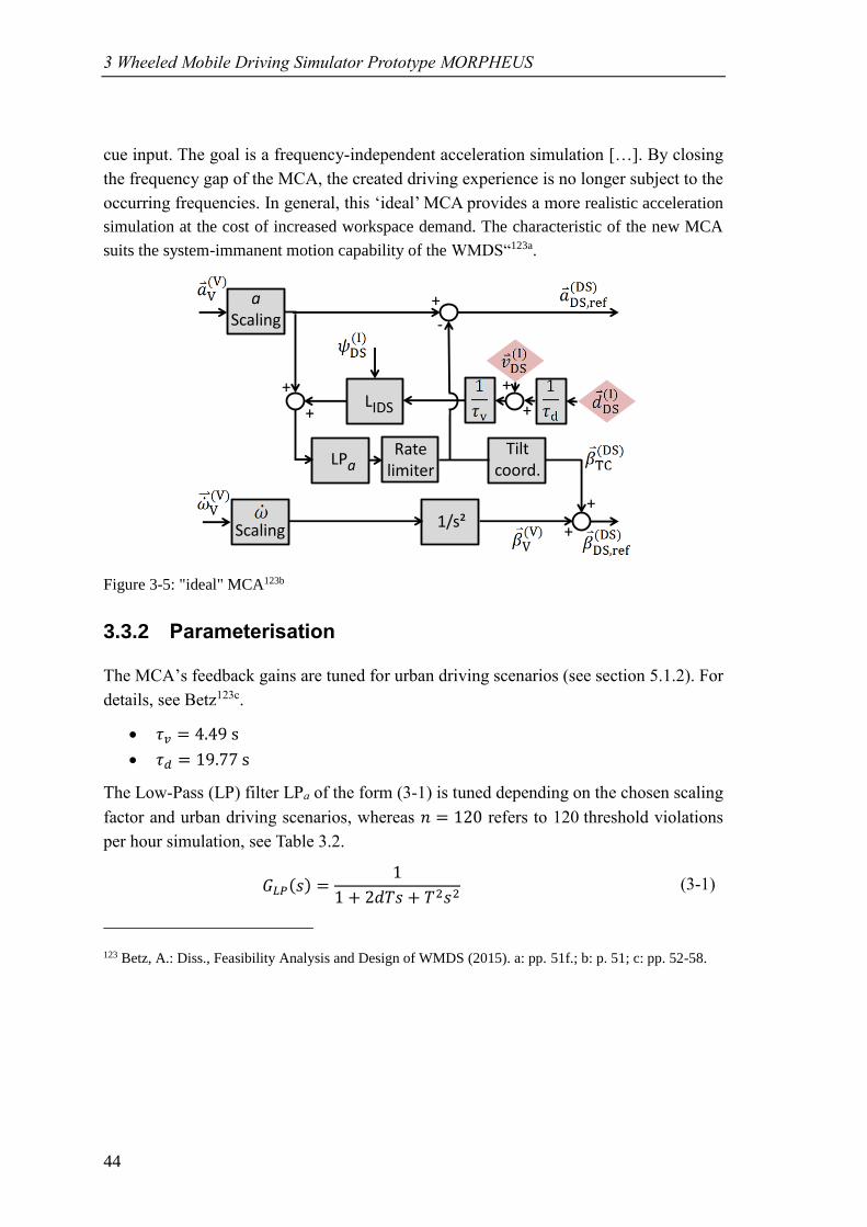
3 Wheeled Mobile Driving Simulator Prototype MORPHEUS
44
cue input. The goal is a frequency-independent acceleration simulation […]. By closing
the frequency gap of the MCA, the created driving experience is no longer subject to the
occurring frequencies. In general, this ‘ideal’ MCA provides a more realistic acceleration
simulation at the cost of increased workspace demand. The characteristic of the new MCA
suits the system-immanent motion capability of the WMDS“123a.
Figure 3-5: "ideal" MCA123b
3.3.2 Parameterisation
The MCA’s feedback gains are tuned for urban driving scenarios (see section 5.1.2). For
details, see Betz123c.
• 𝜏𝑣 = 4.49 s
• 𝜏𝑑 = 19.77 s
The Low-Pass (LP) filter LPa of the form (3-1) is tuned depending on the chosen scaling
factor and urban driving scenarios, whereas 𝑛 = 120 refers to 120 threshold violations
per hour simulation, see Table 3.2.
𝐺𝐿𝑃(𝑠) =1
1 + 2𝑑𝛵𝑠 + 𝛵2𝑠2 (3-1)
123 Betz, A.: Diss., Feasibility Analysis and Design of WMDS (2015). a: pp. 51f.; b: p. 51; c: pp. 52-58.
Scaling
aScaling
LPaTilt
coord.Rate
limiter
1/s²
+
+
+
+LIDS
+
-
+
+
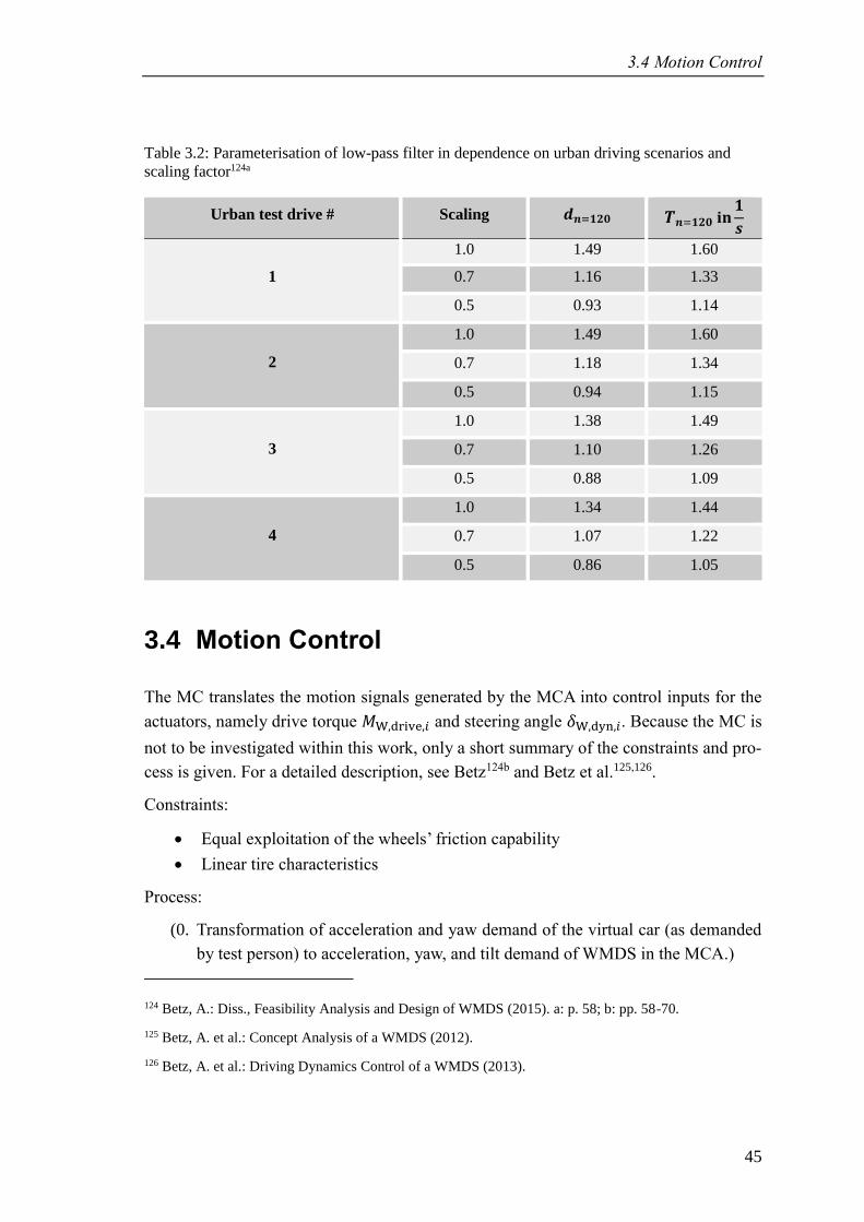
3.4 Motion Control
45
Table 3.2: Parameterisation of low-pass filter in dependence on urban driving scenarios and
scaling factor124a
Urban test drive # Scaling 𝒅𝒏=𝟏𝟐𝟎 𝜯𝒏=𝟏𝟐𝟎 𝐢𝐧𝟏
𝒔
1
1.0 1.49 1.60
0.7 1.16 1.33
0.5 0.93 1.14
2
1.0 1.49 1.60
0.7 1.18 1.34
0.5 0.94 1.15
3
1.0 1.38 1.49
0.7 1.10 1.26
0.5 0.88 1.09
4
1.0 1.34 1.44
0.7 1.07 1.22
0.5 0.86 1.05
3.4 Motion Control
The MC translates the motion signals generated by the MCA into control inputs for the
actuators, namely drive torque 𝑀 ,dri e,𝑖 and steering angle 𝛿 ,dyn,𝑖. Because the MC is
not to be investigated within this work, only a short summary of the constraints and pro-
cess is given. For a detailed description, see Betz124b and Betz et al.125,126.
Constraints:
• Equal exploitation of the wheels’ friction capability
• Linear tire characteristics
Process:
(0. Transformation of acceleration and yaw demand of the virtual car (as demanded
by test person) to acceleration, yaw, and tilt demand of WMDS in the MCA.)
124 Betz, A.: Diss., Feasibility Analysis and Design of WMDS (2015). a: p. 58; b: pp. 58-70.
125 Betz, A. et al.: Concept Analysis of a WMDS (2012).
126 Betz, A. et al.: Driving Dynamics Control of a WMDS (2013).
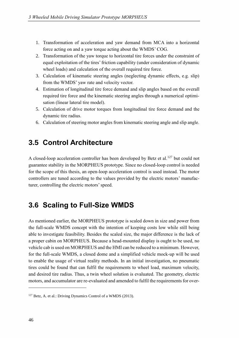
3 Wheeled Mobile Driving Simulator Prototype MORPHEUS
46
1. Transformation of acceleration and yaw demand from MCA into a horizontal
force acting on and a yaw torque acting about the WMDS’ COG.
2. Transformation of the yaw torque to horizontal tire forces under the constraint of
equal exploitation of the tires’ friction capability (under consideration of dynamic
wheel loads) and calculation of the overall required tire force.
3. Calculation of kinematic steering angles (neglecting dynamic effects, e.g. slip)
from the WMDS’ yaw rate and velocity vector.
4. Estimation of longitudinal tire force demand and slip angles based on the overall
required tire force and the kinematic steering angles through a numerical optimi-
sation (linear lateral tire model).
5. Calculation of drive motor torques from longitudinal tire force demand and the
dynamic tire radius.
6. Calculation of steering motor angles from kinematic steering angle and slip angle.
3.5 Control Architecture
A closed-loop acceleration controller has been developed by Betz et al.127 but could not
guarantee stability in the MORPHEUS prototype. Since no closed-loop control is needed
for the scope of this thesis, an open-loop acceleration control is used instead. The motor
controllers are tuned according to the values provided by the electric motors’ manufac-
turer, controlling the electric motors’ speed.
3.6 Scaling to Full-Size WMDS
As mentioned earlier, the MORPHEUS prototype is scaled down in size and power from
the full-scale WMDS concept with the intention of keeping costs low while still being
able to investigate feasibility. Besides the scaled size, the major difference is the lack of
a proper cabin on MORPHEUS. Because a head-mounted display is ought to be used, no
vehicle cab is used on MORPHEUS and the HMI can be reduced to a minimum. However,
for the full-scale WMDS, a closed dome and a simplified vehicle mock-up will be used
to enable the usage of virtual reality methods. In an initial investigation, no pneumatic
tires could be found that can fulfil the requirements to wheel load, maximum velocity,
and desired tire radius. Thus, a twin wheel solution is evaluated. The geometry, electric
motors, and accumulator are re-evaluated and amended to fulfil the requirements for over-
127 Betz, A. et al.: Driving Dynamics Control of a WMDS (2013).
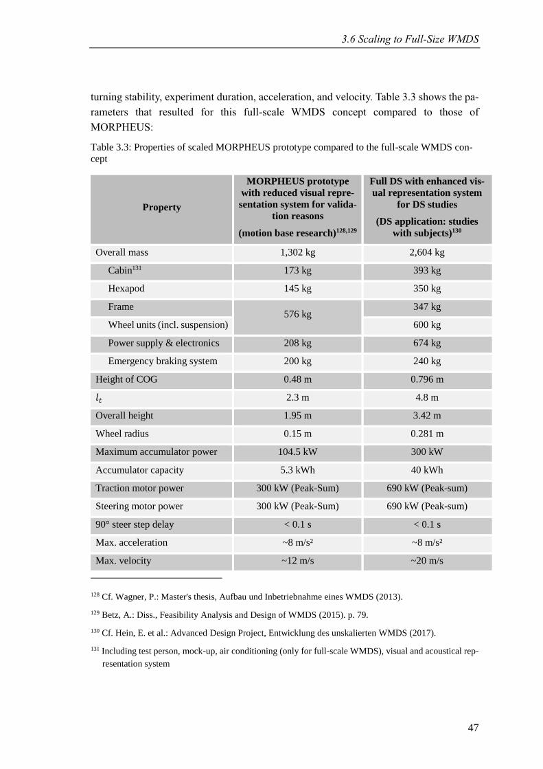
3.6 Scaling to Full-Size WMDS
47
turning stability, experiment duration, acceleration, and velocity. Table 3.3 shows the pa-
rameters that resulted for this full-scale WMDS concept compared to those of
MORPHEUS:
Table 3.3: Properties of scaled MORPHEUS prototype compared to the full-scale WMDS con-
cept
Property
MORPHEUS prototype
with reduced visual repre-
sentation system for valida-
tion reasons
(motion base research)128,129
Full DS with enhanced vis-
ual representation system
for DS studies
(DS application: studies
with subjects)130
Overall mass 1,302 kg 2,604 kg
Cabin131 173 kg 393 kg
Hexapod 145 kg 350 kg
Frame 576 kg
347 kg
Wheel units (incl. suspension) 600 kg
Power supply & electronics 208 kg 674 kg
Emergency braking system 200 kg 240 kg
Height of COG 0.48 m 0.796 m
𝑙𝑡 2.3 m 4.8 m
Overall height 1.95 m 3.42 m
Wheel radius 0.15 m 0.281 m
Maximum accumulator power 104.5 kW 300 kW
Accumulator capacity 5.3 kWh 40 kWh
Traction motor power 300 kW (Peak-Sum) 690 kW (Peak-sum)
Steering motor power 300 kW (Peak-Sum) 690 kW (Peak-sum)
90° steer step delay < 0.1 s < 0.1 s
Max. acceleration ~8 m/s² ~8 m/s²
Max. velocity ~12 m/s ~20 m/s
128 Cf. Wagner, P.: Master's thesis, Aufbau und Inbetriebnahme eines WMDS (2013).
129 Betz, A.: Diss., Feasibility Analysis and Design of WMDS (2015). p. 79.
130 Cf. Hein, E. et al.: Advanced Design Project, Entwicklung des unskalierten WMDS (2017).
131 Including test person, mock-up, air conditioning (only for full-scale WMDS), visual and acoustical rep-
resentation system

3 Wheeled Mobile Driving Simulator Prototype MORPHEUS
48
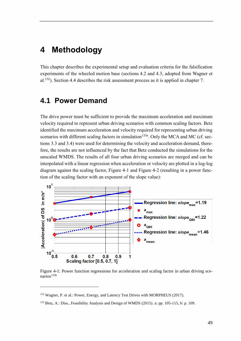
49
4 Methodology
This chapter describes the experimental setup and evaluation criteria for the falsification
experiments of the wheeled motion base (sections 4.2 and 4.3, adopted from Wagner et
al.132). Section 4.4 describes the risk assessment process as it is applied in chapter 7.
4.1 Power Demand
The drive power must be sufficient to provide the maximum acceleration and maximum
velocity required to represent urban driving scenarios with common scaling factors. Betz
identified the maximum acceleration and velocity required for representing urban driving
scenarios with different scaling factors in simulation133a. Only the MCA and MC (cf. sec-
tions 3.3 and 3.4) were used for determining the velocity and acceleration demand, there-
fore, the results are not influenced by the fact that Betz conducted the simulations for the
unscaled WMDS. The results of all four urban driving scenarios are merged and can be
interpolated with a linear regression when acceleration or velocity are plotted in a log-log
diagram against the scaling factor, Figure 4-1 and Figure 4-2 (resulting in a power func-
tion of the scaling factor with an exponent of the slope value):
Figure 4-1: Power function regressions for acceleration and scaling factor in urban driving sce-
narios133b
132 Wagner, P. et al.: Power, Energy, and Latency Test Drives with MORPHEUS (2017).
133 Betz, A.: Diss., Feasibility Analysis and Design of WMDS (2015). a: pp. 105-115, b: p. 109.
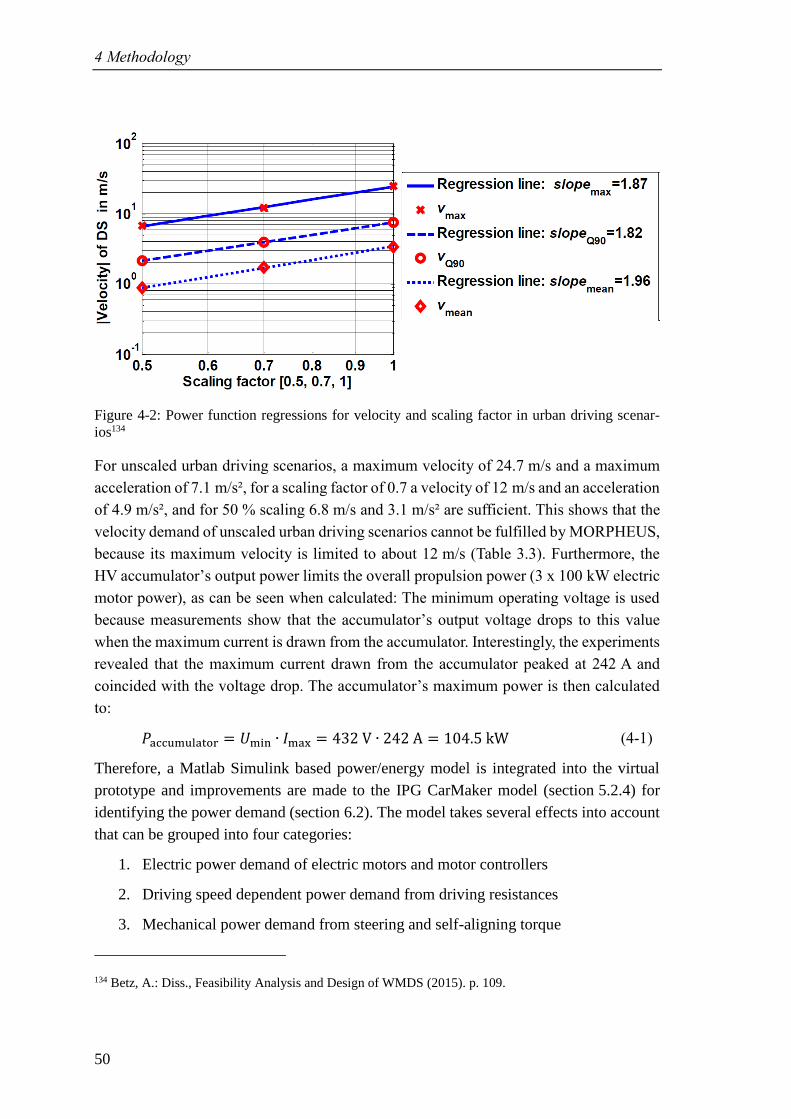
4 Methodology
50
Figure 4-2: Power function regressions for velocity and scaling factor in urban driving scenar-
ios134
For unscaled urban driving scenarios, a maximum velocity of 24.7 m/s and a maximum
acceleration of 7.1 m/s², for a scaling factor of 0.7 a velocity of 12 m/s and an acceleration
of 4.9 m/s², and for 50 % scaling 6.8 m/s and 3.1 m/s² are sufficient. This shows that the
velocity demand of unscaled urban driving scenarios cannot be fulfilled by MORPHEUS,
because its maximum velocity is limited to about 12 m/s (Table 3.3). Furthermore, the
HV accumulator’s output power limits the overall propulsion power (3 x 100 kW electric
motor power), as can be seen when calculated: The minimum operating voltage is used
because measurements show that the accumulator’s output voltage drops to this value
when the maximum current is drawn from the accumulator. Interestingly, the experiments
revealed that the maximum current drawn from the accumulator peaked at 242 A and
coincided with the voltage drop. The accumulator’s maximum power is then calculated
to:
𝑃a umulator = 𝑈min ∙ 𝐼max = 432 V ∙ 242 = 104.5 kW (4-1)
Therefore, a Matlab Simulink based power/energy model is integrated into the virtual
prototype and improvements are made to the IPG CarMaker model (section 5.2.4) for
identifying the power demand (section 6.2). The model takes several effects into account
that can be grouped into four categories:
1. Electric power demand of electric motors and motor controllers
2. Driving speed dependent power demand from driving resistances
3. Mechanical power demand from steering and self-aligning torque
134 Betz, A.: Diss., Feasibility Analysis and Design of WMDS (2015). p. 109.
4.2 Energy Demand
51
4. Mechanical power demand at wheel hubs, accounting for slip losses and transla-
tional as well as rotational acceleration resistance
These effects are parameterised by conducting synthetic manoeuvres (namely coasting
experiments, holding torque experiments, and straight-line acceleration experiments, sec-
tion 6.1.1) with MORPHEUS and measuring the platform’s energy demand. Simple
straight-line driving manoeuvres (section 5.1.1.1) with constant acceleration are con-
ducted to verify the power model (section 6.1.2.1).
The aspect power demand falsifies hypothesis H1.1 if FZD’s WMDS concept cannot rep-
resent the required maximum acceleration and velocity amplitudes with state-of-the-art
technology.
4.2 Energy Demand
Energy is converted by the platform, the hexapod, and auxiliaries. Because the available
driving area is not sufficient to drive unscaled urban driving scenarios (section 5.1.2) with
MORPHEUS – which constitute the most realistic application with maximum energy de-
mand – the virtual prototype is used to determine the platform’s energy demand by inte-
grating the power model over time. The resulting energy model is validated by conducting
scaled synthetic and representative manoeuvres (namely a 90° turn, a figure eight, and an
urban driving scenario, sections 5.1.1.4, 5.1.1.5, and 5.1.2) with MORPHEUS and com-
paring the measured energy demand to the simulated energy demand (section 6.1.2.2).
Finally, the maximum energy demand of MORPHEUS is determined by simulating un-
scaled, representative urban driving scenarios with the validated energy model (sec-
tion 6.3.1). The overall energy demand is then calculated by adding the estimated demand
of the hexapod and the measured energy demand of Low Voltage (LV) auxiliaries (e.g.
safety system, power electronics, measurement technology) (section 6.3.2).
The aspect energy demand falsifies hypothesis H1.1 if the results from the verified energy
model prove that unscaled urban driving simulation cannot be represented with state-of-
the-art accumulator technology for at least 2 h, considering state-of-the-art technology.
4.3 Acceleration Cue Latency
To identify the worst-case latency in the motion system, synthetic manoeuvres are used
with MORPHEUS. Because of the omnidirectionality of WMDS, the latency require-
ments cannot be clearly divided into longitudinal and lateral motion. Even more, latency
is expected to depend on the wheels’ orientation and to behave identical for lateral and
4 Methodology
52
longitudinal motion cues. In contrast, a passenger car has a distinctive orientation, hence
latency is different for lateral and longitudinal motion, and different measurement indi-
cators are used for determining lateral and longitudinal motion latency. Therefore, the
manoeuvre with the worst-case latency must be identified for MORPHEUS, analysed
with the gaining and 50 % criteria for ACL, and evaluated for the minimum acceleration
latency as it can be found in passenger cars (section 2.5.3.2). Section 4.3.1 describes the
difference in latency between WMDS and passenger cars in detail and therewith identifies
the manoeuvre with the worst-case latency for MOPRHEUS. Sections 4.3.2 to 4.3.4 de-
scribe the experimental setup, the evaluation methodology and give a conclusion, respec-
tively.
4.3.1 Latency in a WMDS and in a Passenger Car
Latency in a WMDS’ acceleration representation arises from delayed force transmission
in the desired direction. This delay is influenced by the response behaviour of the electric
motors and by the wheel units’ current state of operation. The response behaviour can be
influenced by the control parameters that are tuned iteratively. The wheel units’ state of
operation is strongly dependent on the current DS state and can be discriminated into
seven cases in dependence on the yaw angle, acceleration demand, and WMDS velocity:
1. Identical yaw angle in DS’ COS as in vehicle’s COS:
1.1. Lateral acceleration demand
1.1.1. WMDS driving velocity well above zero: Like in a real car, slip angle must
be generated at the wheels to build up lateral tire force.
1.1.2. WMDS driving velocity close to zero: Whereas the vehicle’s driving ve-
locity is high enough for building up sufficient lateral tire force through
slip angle, the WMDS’ wheels must re-orientate so that they align with the
desired direction of motion to provide the lateral acceleration using the
drive motor. For re-orientating the wheels, the steering unit’s friction
torque, the tire’s drill torque and the moment of inertia must be overcome.
1.2. Longitudinal acceleration demand: The drive motors must only overcome the
drive unit’s friction torque and moment of inertia. The remaining drive torque
can be used for acceleration. The driving velocity has no influence on latency,
given that the motor power is sufficient for accelerating.
2. Different yaw angle in DS’ COS as in vehicle’s COS (can only occur with a low-
frequent acceleration demand → washout is active):
2.1. Lateral acceleration demand
4.3 Acceleration Cue Latency
53
2.1.1. WMDS driving velocity well above zero: Lateral tire force can be gener-
ated by slip angle, although the wheels must be re-orientated first by less
than 90°. The steering unit’s friction torque, the drill torque, and the mo-
ment of inertia must be overcome.
2.1.2. WMDS driving velocity close to zero: In the worst case, the wheels are
perpendicular to the desired direction of motion and must be re-orientated
first. The steering unit’s friction torque, the drill torque, and the moment
of inertia must be overcome.
2.2. Longitudinal acceleration demand: 2.2.1 and 2.2.2 as with lateral acceleration
demand (case 2.1.1 and 2.1.2).
Clearly, cases 1.1.1 and 1.2 are least critical. For cases 1.1.2 and 2 the latency that is also
caused in case 1.2 (drive unit’s friction torque and moment of inertia) is supplemented by
the latency needed for re-orientating the wheels – in a worst-case by 90° (steering unit’s
friction torque, drill torque, and moment of inertia must be overcome). Figure 4-3 demon-
strates the difference in tire force transmission for a lateral acceleration step input in a
real vehicle (or virtual vehicle, left) and a WMDS (right), which is equivalent to
case 1.1.2. When lateral acceleration is demanded in a moving vehicle, the wheels are
steered into the desired direction, thus generating slip angle leading to the build-up of
lateral tire force and, therewith, lateral acceleration. In the WMDS, however, the local
yaw angle does not necessarily comply with the vehicle’s yaw angle. Still, the overall
vestibular driving impression, in this case especially the horizontal acceleration, must
correlate. Due to the washout, the WMDS’ velocity can be reduced to near zero if the
WMDS’ accelerations match the vehicle’s acceleration (superposed by TC) plus or minus
the human perception threshold for translational acceleration 𝑎threshold.
Concluding, the worst-case latency occurs when the wheels are misaligned by 90° to the
desired direction of acceleration and the driving velocity is near zero. As demonstrated in
Figure 4-3 the side slip angle of WMDS can reach 90°, unlike a regular passenger car.
Therefore, it is sufficient to measure the worst-case latency for either longitudinal or lat-
eral acceleration, which is why only lateral acceleration step inputs are used in the exper-
iments. Nevertheless, different acceptable latency limits apply for lateral and longitudinal
acceleration in a real car. Thus, the lateral acceleration experiments are analysed with the
criteria for gaining (𝑡 ain, IACLgain) and 50 % (𝑡50 %, IACL50 %) acceleration cue latency
and evaluated with the minimum lateral and longitudinal acceleration latency of a real
car.
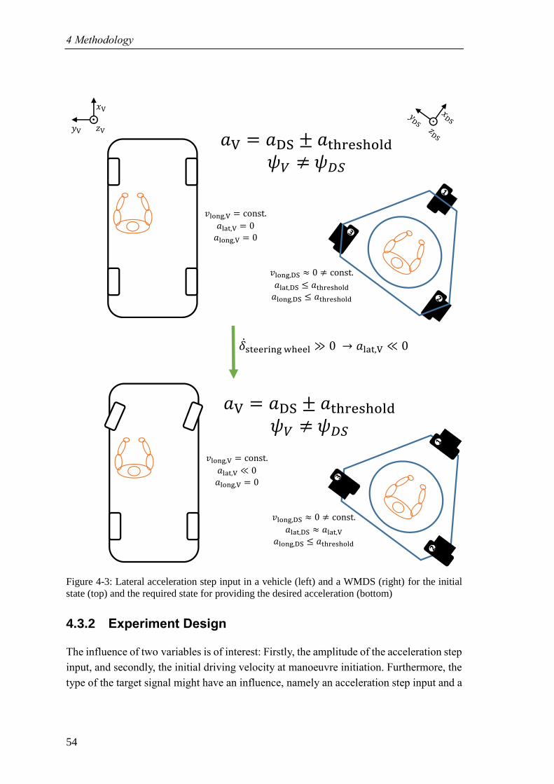
4 Methodology
54
Figure 4-3: Lateral acceleration step input in a vehicle (left) and a WMDS (right) for the initial
state (top) and the required state for providing the desired acceleration (bottom)
4.3.2 Experiment Design
The influence of two variables is of interest: Firstly, the amplitude of the acceleration step
input, and secondly, the initial driving velocity at manoeuvre initiation. Furthermore, the
type of the target signal might have an influence, namely an acceleration step input and a
𝑥
𝑦 𝑧
𝑣lon , = const.
𝑎lat, = 0𝑎lon , = 0
𝑣lon ,DS 0 const.
𝑎lat,DS 𝑎threshold𝑎lon ,DS 𝑎threshold
𝑎 = 𝑎DS ± 𝑎threshold𝜓 𝜓
�̇�steerin heel 0 𝑎lat, 0
𝑣lon , = const.
𝑎lat, 0𝑎lon , = 0
𝑣lon ,DS 0 const.
𝑎lat,DS 𝑎lat, 𝑎lon ,DS 𝑎threshold
𝑎 = 𝑎DS ± 𝑎threshold𝜓 𝜓
4.3 Acceleration Cue Latency
55
steering angle step input. Therefore, an experiments design is chosen so that a minimum
number of experiments clarifies how latency is influenced in a WMDS:
1. Variation of lateral acceleration step input amplitude from 1 m/s² to 8 m/s² in
1 m/s² increments and with an initial longitudinal velocity of 0 and 1 m/s.
2. Variation of initial longitudinal velocity
a. with an acceleration step input amplitude of 5 m/s² and with initial longi-
tudinal velocities of 0 to 6 m/s in 1 m/s increments.
b. With a 90° (i.e. maximum) steering angle step input with initial longitudi-
nal velocities of 1 m/s to 6 m/s in 1 m/s increments.
Thus, the first experiment investigates the influence of the acceleration step input ampli-
tude in detail and the influence of the initial longitudinal velocity at low speeds. Higher
speeds are not driven because the most significant influence of the initial velocity is ex-
pected at low speeds due to the drilling torque. The second experiments investigate the
detailed influence of longitudinal velocity up to medium speeds for one acceleration step
input and steering angle step input and thereby also investigates the influence of the type
of control input. Thus, it can be proven if the assumption of negligible influence of the
initial velocity at speeds above 1 m/s is valid.
4.3.3 Experiment Assessment
ACL50 % is calculated by subtracting the manoeuvre initiation time (e.g. acceleration step
input) from the time when 50 % of the target acceleration is reached (IACL50 %). For cal-
culating ACLgain, an indicator to determine the time when the system is reacting to the
control input is needed, too. Latency is then calculated as the difference between the time
of indication and the time of manoeuvre initiation. In passenger cars, the first increase in
yaw rate or lateral acceleration is used as an indicator for the vehicle’s reaction to the
control input. Because lateral motion in a driving simulator is not necessarily connected
to yaw motion, it is advisable to use lateral acceleration as an indicator instead. This as-
sumption is eligible because in a car yaw motion is induced by lateral acceleration making
the investigation conservative. Since the overall aim is to represent acceleration to a hu-
man test person, it is obvious to use the human perception threshold of 0.2 m/s² (cf. sec-
tion 2.5.2) as an indicator, yielding IACLgain.
All experiments are analysed with the IACL50 % and the IACLgain. For experiment 2a (var-
iation of the initial longitudinal velocity with a steering angle step input), however, a
target steering angle is set instead of a target acceleration. Therefore, IACL50 % is defined
as the time when 50 % of the maximum acceleration resulting from the steering angle
step input is reached, yielding a conservative value.
4 Methodology
56
4.3.4 Summary
Each experiment is carried out six times, yielding 174 data sets for evaluating ACL50 %
and ACLgain.
The aspect motion cue latency falsifies hypothesis H1.1 if the hardware prototype cannot
reach 50 % of any acceleration step input within 135 ms and 0.2 m/s² after any accelera-
tion or steering angle step input within 100 ms at any velocity, considering state-of-the-
art technology.
4.4 Risk Assessment
The most relevant safety standards have been introduced in section 2.3. The ISO 26262
is intended for automotive series production and is therefore not ideal for prototypes. The
EN ISO 13849 and the IEC/EN 62061 are focussed on E/E/PE control systems. Thus, the
IEC 61508, which is often referred to as the “mother standard for E/E/PE system safety”,
is applied.
Risk assessment is dealt with in IEC 60300 “Dependability management”, whereas the
part most important for HARA, the IEC 60300-3-9 “Risk analysis of technological sys-
tems”, has been evolved into the ISO/IEC 31010 “Risk management – Risk assessment
techniques”135. The ISO/IEC 31010 proposes a total of 31 risk assessment techniques that
can also be found in Ericson’s “Hazard analysis techniques for system safety”, which is
more focused on the overarching safety aspects rather than functional safety. Ericson
states “one of the annoying truisms of system safety is that it is usually easier to mitigate
a hazard than it is to recognize or find the hazard in the first place”136. Therefore, the goal
is to identify hazards to the fullest extent possible. Although structured approaches, e.g.
Figure 2-17, exist, 100 % safety cannot be guaranteed. This makes it even more important
to be thorough on elaborating each and every step in the risk assessment process.
The focus of this thesis is on functional safety and, therefore, the chosen methodology is
closer to IEC 61508 than to the elaborate methods as described by Ericson. The risk graph
is the only risk estimation method that is described in all aforementioned standards and
will be used here as well. The structure, as chosen with sections 4.4.1 to 4.4.4, is adapted
from EN ISO 13849 (cf. Figure 2-17). A sufficient mechanical strength of the components
135 ISO/TC 262 - Risk management: IEC 31010 (2009).
136 Ericson, C. A.: Hazard Analysis Techniques for System Safety (2005). p. 24.
4.4 Risk Assessment
57
is assumed. Faults like loose connectors and/or worn through cables are not included di-
rectly. Still, signal dropouts are a matter of functional safety and, therewith, take faulty
cables/connectors indirectly into account.
4.4.1 Determination of the Limits of Machinery
The determination of the limits of machinery can also be found in the overall safety lifecy-
cle in IEC 61508 (Figure 2-15), represented by phases one and two: concept and overall
scope definition.
Ericson describes a hazard triangle137 that is comprised of three elements:
1. Hazardous element: A basic hazardous resource, e.g. energy
2. Initiating mechanism: The trigger or initiator event(s)
3. Target and threat: The person or thing that is vulnerable to injury and/or damage
Only if all three elements are present, a hazard can arise. Knowing about these basic ele-
ments enables the design engineer to search the system for them. Generic checklists can
help because possible hazards that can be caused by single elements are pointed out. This
also underlines the importance of determining the limits of the system under investigation
properly, including:
• System components (structural elements)
• System design (flow of forces, energy, information)
• System functions (what is the system intended/designed to do?)
• Energy sources (electric, hydraulic, pneumatic, chemical, etc.)
• Concepts for operation (who will be using the system with which expertise and in
which mode, e.g. regular operation, maintenance, repair, transport, etc.)
• External conditions (e.g. climate, electromagnetic compatibility, etc.)
The results of this process are a complete description of the EUC, likely sources of haz-
ards (hazardous elements, initiating mechanisms, and targets and threats), and infor-
mation about the current safety regulations.
4.4.2 Hazard Identification
A hazard is defined by a failure (e.g. no power supply) and the consequence of the failure
(in this case no acceleration/deceleration or steering possible). The hazard identification
is included in the third phase, HARA, of the overall safety lifecycle in IEC 61508 (Figure
2-15). Clause 7.4.2.1 of IEC 61508 states if “decisions are taken [...] which may change
137 Ericson, C. A.: Hazard Analysis Techniques for System Safety (2005). p. 17.
4 Methodology
58
the basis on which the earlier decisions were taken, then a further HARA shall be under-
taken”138, underlining that conducting a HARA is an iterative process. Ericson advises to
utilise past knowledge, evaluate top-level mishaps and finally yet importantly use generic
hazard (source) checklists, also provided by Ericson. Still, the process of risk analysis,
especially hazard identification, is rather intuitive; the predominant method for hazard
identification is brainstorming, although supported by structured approaches leading
through the identification process, e.g.:
• Dividing complex systems into subsystems and precisely working out the infor-
mation and power flow between and within the subsystems.
• Splitting components into sensors, actuators, and electronic control units.
• Evaluating possible failures that could arise from the component’s intended func-
tions.
• Conducting FTA or FME(C)A
Conducting the hazard identification in a team of experts increases the probability of
identifying all relevant hazards. The IEC 61822 “Hazard and operability studies (HAZOP
studies) - Application guide”139 gives a guideline towards structured and systematic ex-
amination of hazards. For identifying hazards, twelve guidewords are introduced. If a
guideword is applicable to an intended function of the EUC, the combination of the two
must be reviewed to find out if it constitutes a hazard to the system. The guidewords are:
Table 4.1: Guidewords for hazard identification139
Guideword Meaning
NO OR NOT Complete negation of the design intent
MORE Quantitative increase
LESS Quantitative decrease
AS WELL AS Qualitative modification/increase
PART OF Qualitative modification/decrease
REVERSE Logical opposite of the design intent
OTHER THAN / INSTEAD Complete substitution
EARLY Relative to the clock time
LATE Relative to the clock time
BEFORE Relating to order or sequence
AFTER Relating to order or sequence
138 IEC TC 65/SC 65A - System aspects: IEC 61508 (2011). p. 27.
139 IEC TC 56 - Dependability: IEC 61882 (2016).
4.4 Risk Assessment
59
As an example, the function supply demanded power to drive motor is investigated. For
this function, it must be investigated if it constitutes a hazard in case no/more/less power
is supplied, power as well as or as part of another signal is supplied, power is drawn rather
than supplied, another signal instead of power is supplied, or power is supplied late/early
or before/after a specific event.
The result of the hazard identification is a – to the best of one’s knowledge – complete
list of all hazards, whereas the situation, in which each hazard occurs, is not of interest,
yet.
4.4.3 Risk Estimation
The risk estimation is also included in the third phase, HARA, of the overall safety lifecy-
cle in IEC 61508 (Figure 2-15). The goal of the risk estimation is to assign each hazard
that has been identified in the previous process (section 4.4.2) to a risk level. The combi-
nation of a hazard and a critical operational situation yields a hazardous event, whose risk
can be evaluated. It is not advisable to list each possible situation, because most situations
will be uncritical and are not worth looking at. Therefore, the expert conducting the anal-
ysis may choose the most critical situation. If it is unclear which situation is the most
critical, it is also valid to extend the hazard to a few situations.
The definition of the risk level depends on the standard (performance level in
EN ISO 13849, automotive SIL in ISO 26262, or SIL in IEC 61508), whereas the SIL
will be used in this thesis. In any case, a hazard’s consequences, its probability of occur-
rence (the situation and the mishap), and its controllability must be evaluated. If no valid
data exists for evaluating these hazard parameters (which usually is the case), a qualitative
evaluation is performed by estimating the level of each risk parameter. As with the hazard
identification, this process is rather intuitive and decisions about allocations can be ar-
gued. The most common qualitative method for evaluating the risk level (independent of
the chosen metric) is the risk graph, Figure 2-16. In addition, a solution for mitigating
each risk is formulated.
The result of the risk estimation is a – to the best of one’s knowledge – complete list of
all hazards that includes – for each and every hazard – a description of the situation, an
evaluation of the risk/assignment of a risk level, and a proposal of a risk reduction method.
4.4.4 Risk Evaluation
The risk evaluation includes the fourth and fifth phases, namely overall safety require-
ments and safety requirement allocation, of the overall safety lifecycle in IEC 61508
(Figure 2-15). The goals are to establish the overall safety requirements (or safety goals
according to ISO 26262) and to evaluate if the overall risk that arises from the system has
4 Methodology
60
been adequately reduced. The overall safety requirements are comprised of the safety
functions requirements (i.e. the function that is intended to reduce the risk, derived from
the hazard analysis) and the safety integrity requirements (i.e. the risk reduction required
(SIL in case of IEC 61508), derived from the risk analysis). At this stage, the safety func-
tion must not be specified in technology-specific terms. Also, the definition of the safety
functions must be done regardless of the hazardous event’s situation. Otherwise, the
safety function could reduce the risk of the specific hazardous event, but not the risk of
other hazardous events that are associated with the same failure and consequence but in
different, less critical situations (which possibly result in a lower SIL and are therefore
not listed in the HARA). If the risk has been adequately reduced, no further measures are
needed. If not, a risk reduction process is triggered (Figure 2-17). The architectural or
processual changes that are made within the risk reduction process may require an addi-
tional risk assessment process or a re-assessment of the whole EUC.
The result of the risk evaluation is a – to the best of one’s knowledge – complete overall
safety requirements list that must be met to call the EUC safe. The aspect safety architec-
ture falsifies hypothesis H1.2 if no architecture can be found that reduces the identified
risks to an acceptable level.
61
5 Research Tools
Section 5.1 of this chapter describes the synthetic and representative test manoeuvres that
are used in the falsification experiments of the wheeled mobile platform, followed by a
description of the virtual prototype (section 5.2) that is used for extrapolating the falsifi-
cation experiments. Section 5.3 describes the measurement technology used with
MORPHEUS and how signals are processed and is adopted from Wagner et al.140.
5.1 Test Manoeuvres
Synthetic and representative test manoeuvres are used within this thesis, depending on
the research aim. All experiments are carried out on the August-Euler-Airfield in Darm-
stadt.
5.1.1 Synthetic Manoeuvres
Here, only those synthetic manoeuvres that are required for conducting experiments and
simulation runs are described. The justifications for the choice of these manoeuvres are
given in the sections where they are applied. Synthetic manoeuvres are artificially gener-
ated and, therefore, the input signals are noise-free. All synthetic manoeuvres are driven
without washout and TC. For the 90° turn and the figure eight, scaling is applied in the
MCA when necessary.
5.1.1.1 Straight-Line Acceleration
This manoeuvre is used for the verification of the power demand and the determination
of the electric drive motor’s and its motor controller’s electrical efficiency that is used in
the power/energy model. A longitudinal acceleration step input of constant amplitude is
imposed to the DS at standstill up to its maximum velocity.
5.1.1.2 Steering Angle Step Input
A 90° steering angle step input is imposed to the DS, whereas the driving velocity may
be varied. This manoeuvre is used for the determination of ACL.
140 Wagner, P. et al.: Power, Energy, and Latency Test Drives with MORPHEUS (2017).
5 Research Tools
62
5.1.1.3 Perpendicular Acceleration Step Input
An acceleration step input is imposed to the DS, whereas the initial, perpendicular driving
velocity may be varied. The acceleration step input amplitude may be varied, too. This
manoeuvre is used for the determination of ACL.
5.1.1.4 90° Turn
The 90° turn (a.k.a. T-junction) is approached with 14 m/s. Then the vehicle is decelerated
with 3 m/s² down to 5 m/s. As soon as the target velocity is reached, cornering is initiated
with constant velocity. The cornering radius is 10 m. After a change in orientation of 90°
has been reached, the vehicle accelerates with 3 m/s² to 14 m/s. The resulting accelera-
tion, velocity, and yaw profile is processed in the MC (no washout and TC) and scaled if
necessary141a. This manoeuvre is used to verify the energy model.
5.1.1.5 Figure Eight
The Figure eight manoeuvre is originally intended to evaluate the control and tire behav-
iour. It is driven at a constant longitudinal velocity of 1.5 m/s, whereas the heading of the
WMDS follows the trajectory, i.e. with yaw. The cornering radius is 7.5 m, resulting in a
maximum lateral acceleration of ±0.3 m/s². The resulting acceleration, velocity, and yaw
profile is processed in the MC (no washout and TC) and scaled if necessary141b. This
manoeuvre is used to verify the energy model.
5.1.2 Representative Manoeuvres
Graupner has developed a representative urban driving circuit that is composed of ma-
noeuvres in a probabilistic distribution as they can be found in real urban driving142. Four
different drivers that were familiar with the driving circuit drove the measurement runs
during the day, off-hour, resulting in an above-average performance compared to normal
drivers. The car used was a VW Golf VI R, equipped with a GeneSys ADMA G-3 meas-
urement unit, logging translational accelerations and rotational velocities at a sampling
rate of 100 Hz. The circuit is about 21 km long and takes about one hour to com-
plete141c,143. The urban measurement runs are used for the evaluation of the energy de-
mand, where MORPHEUS must represent the recorded accelerations.
Because the measured acceleration and velocity signals are prone to sensor noise and
vibration induced from the test vehicle, filtering is applied. The reason is that in a real DS
application the control inputs for the MCA are firstly generated by the driver through the
141 Cf. Betz, A.: Diss., Feasibility Analysis and Design of WMDS (2015). a: pp. 90f.; b: pp. 91ff.; c: pp.
93f.
142 Graupner, M.: Bachelor's thesis, Entwicklung eines repräsentativen Stadtparcours (2011).
143 Betz, A. et al.: Motion Analysis of a WMDS (2012).
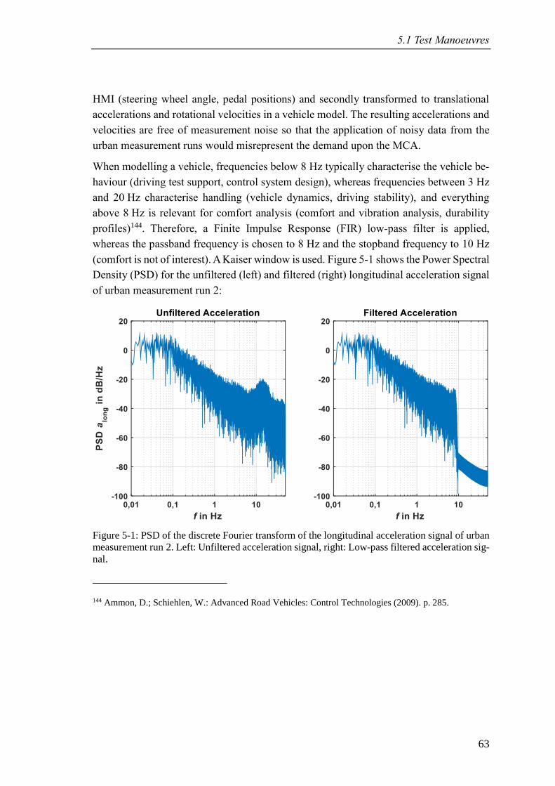
5.1 Test Manoeuvres
63
HMI (steering wheel angle, pedal positions) and secondly transformed to translational
accelerations and rotational velocities in a vehicle model. The resulting accelerations and
velocities are free of measurement noise so that the application of noisy data from the
urban measurement runs would misrepresent the demand upon the MCA.
When modelling a vehicle, frequencies below 8 Hz typically characterise the vehicle be-
haviour (driving test support, control system design), whereas frequencies between 3 Hz
and 20 Hz characterise handling (vehicle dynamics, driving stability), and everything
above 8 Hz is relevant for comfort analysis (comfort and vibration analysis, durability
profiles)144. Therefore, a Finite Impulse Response (FIR) low-pass filter is applied,
whereas the passband frequency is chosen to 8 Hz and the stopband frequency to 10 Hz
(comfort is not of interest). A Kaiser window is used. Figure 5-1 shows the Power Spectral
Density (PSD) for the unfiltered (left) and filtered (right) longitudinal acceleration signal
of urban measurement run 2:
Figure 5-1: PSD of the discrete Fourier transform of the longitudinal acceleration signal of urban
measurement run 2. Left: Unfiltered acceleration signal, right: Low-pass filtered acceleration sig-
nal.
144 Ammon, D.; Schiehlen, W.: Advanced Road Vehicles: Control Technologies (2009). p. 285.
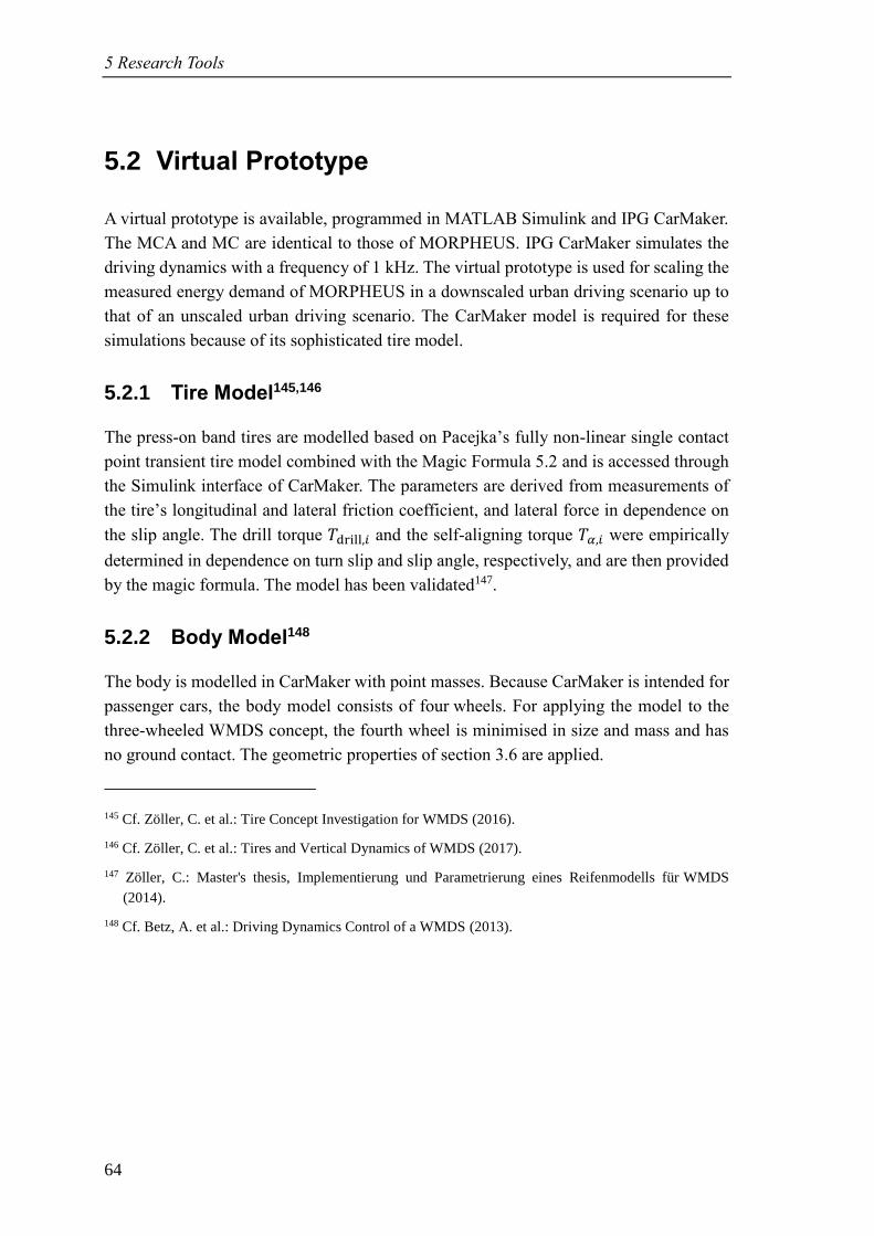
5 Research Tools
64
5.2 Virtual Prototype
A virtual prototype is available, programmed in MATLAB Simulink and IPG CarMaker.
The MCA and MC are identical to those of MORPHEUS. IPG CarMaker simulates the
driving dynamics with a frequency of 1 kHz. The virtual prototype is used for scaling the
measured energy demand of MORPHEUS in a downscaled urban driving scenario up to
that of an unscaled urban driving scenario. The CarMaker model is required for these
simulations because of its sophisticated tire model.
5.2.1 Tire Model145,146
The press-on band tires are modelled based on Pacejka’s fully non-linear single contact
point transient tire model combined with the Magic Formula 5.2 and is accessed through
the Simulink interface of CarMaker. The parameters are derived from measurements of
the tire’s longitudinal and lateral friction coefficient, and lateral force in dependence on
the slip angle. The drill torque 𝑇drill,𝑖 and the self-aligning torque 𝑇𝛼,𝑖 were empirically
determined in dependence on turn slip and slip angle, respectively, and are then provided
by the magic formula. The model has been validated147.
5.2.2 Body Model148
The body is modelled in CarMaker with point masses. Because CarMaker is intended for
passenger cars, the body model consists of four wheels. For applying the model to the
three-wheeled WMDS concept, the fourth wheel is minimised in size and mass and has
no ground contact. The geometric properties of section 3.6 are applied.
145 Cf. Zöller, C. et al.: Tire Concept Investigation for WMDS (2016).
146 Cf. Zöller, C. et al.: Tires and Vertical Dynamics of WMDS (2017).
147 Zöller, C.: Master's thesis, Implementierung und Parametrierung eines Reifenmodells für WMDS
(2014).
148 Cf. Betz, A. et al.: Driving Dynamics Control of a WMDS (2013).
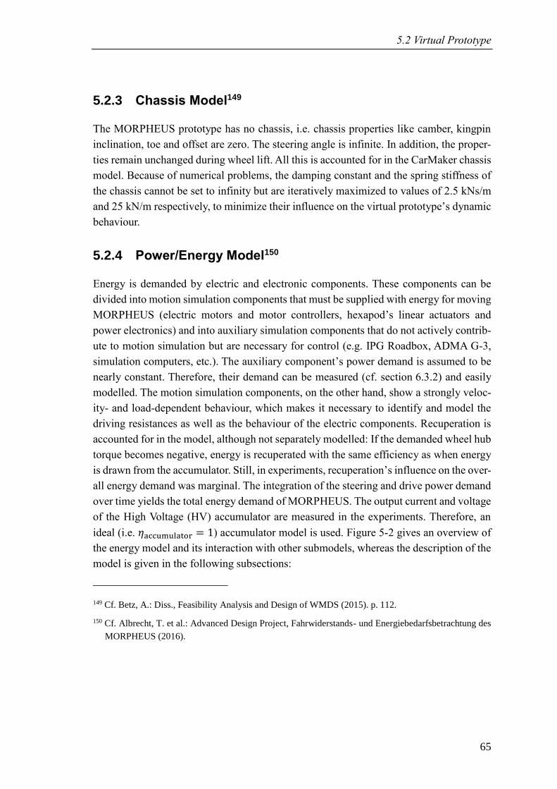
5.2 Virtual Prototype
65
5.2.3 Chassis Model149
The MORPHEUS prototype has no chassis, i.e. chassis properties like camber, kingpin
inclination, toe and offset are zero. The steering angle is infinite. In addition, the proper-
ties remain unchanged during wheel lift. All this is accounted for in the CarMaker chassis
model. Because of numerical problems, the damping constant and the spring stiffness of
the chassis cannot be set to infinity but are iteratively maximized to values of 2.5 kNs/m
and 25 kN/m respectively, to minimize their influence on the virtual prototype’s dynamic
behaviour.
5.2.4 Power/Energy Model150
Energy is demanded by electric and electronic components. These components can be
divided into motion simulation components that must be supplied with energy for moving
MORPHEUS (electric motors and motor controllers, hexapod’s linear actuators and
power electronics) and into auxiliary simulation components that do not actively contrib-
ute to motion simulation but are necessary for control (e.g. IPG Roadbox, ADMA G-3,
simulation computers, etc.). The auxiliary component’s power demand is assumed to be
nearly constant. Therefore, their demand can be measured (cf. section 6.3.2) and easily
modelled. The motion simulation components, on the other hand, show a strongly veloc-
ity- and load-dependent behaviour, which makes it necessary to identify and model the
driving resistances as well as the behaviour of the electric components. Recuperation is
accounted for in the model, although not separately modelled: If the demanded wheel hub
torque becomes negative, energy is recuperated with the same efficiency as when energy
is drawn from the accumulator. Still, in experiments, recuperation’s influence on the over-
all energy demand was marginal. The integration of the steering and drive power demand
over time yields the total energy demand of MORPHEUS. The output current and voltage
of the High Voltage (HV) accumulator are measured in the experiments. Therefore, an
ideal (i.e. 𝜂a umulator = 1) accumulator model is used. Figure 5-2 gives an overview of
the energy model and its interaction with other submodels, whereas the description of the
model is given in the following subsections:
149 Cf. Betz, A.: Diss., Feasibility Analysis and Design of WMDS (2015). p. 112.
150 Cf. Albrecht, T. et al.: Advanced Design Project, Fahrwiderstands- und Energiebedarfsbetrachtung des
MORPHEUS (2016).
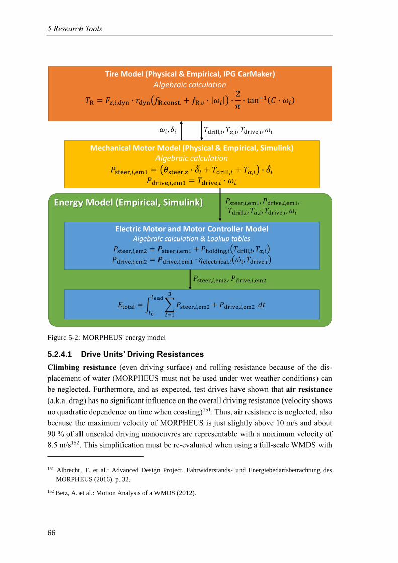
5 Research Tools
66
Figure 5-2: MORPHEUS' energy model
5.2.4.1 Drive Units’ Driving Resistances
Climbing resistance (even driving surface) and rolling resistance because of the dis-
placement of water (MORPHEUS must not be used under wet weather conditions) can
be neglected. Furthermore, and as expected, test drives have shown that air resistance
(a.k.a. drag) has no significant influence on the overall driving resistance (velocity shows
no quadratic dependence on time when coasting)151. Thus, air resistance is neglected, also
because the maximum velocity of MORPHEUS is just slightly above 10 m/s and about
90 % of all unscaled driving manoeuvres are representable with a maximum velocity of
8.5 m/s152. This simplification must be re-evaluated when using a full-scale WMDS with
151 Albrecht, T. et al.: Advanced Design Project, Fahrwiderstands- und Energiebedarfsbetrachtung des
MORPHEUS (2016). p. 32.
152 Betz, A. et al.: Motion Analysis of a WMDS (2012).
Energy Model (Empirical, Simulink)
Tire Model (Physical & Empirical, IPG CarMaker)Algebraic calculation
𝑇 = ,𝑖,dyn dyn 𝑓 , onst. + 𝑓 ,𝑣 𝜔𝑖 2
𝜋 t n−1 𝜔𝑖
𝑇drill,𝑖 , 𝑇𝛼,𝑖 , 𝑇dri e,𝑖 , 𝜔𝑖
Electric Motor and Motor Controller ModelAlgebraic calculation & Lookup tables
𝑃steer,𝑖,em2 = 𝑃steer,𝑖,em1 + 𝑃holdin ,𝑖 𝑇drill,𝑖 , 𝑇𝛼,𝑖𝑃dri e,𝑖,em2 = 𝑃dri e,𝑖,em1 𝜂ele tri al,𝑖 𝜔𝑖̇ , 𝑇dri e,𝑖
𝑃steer,𝑖,em1, 𝑃dri e,𝑖,em1,𝑇drill,𝑖 , 𝑇𝛼,𝑖 , 𝑇dri e,𝑖 , 𝜔𝑖
𝑃steer,𝑖,em2, 𝑃dri e,𝑖,em2
Mechanical Motor Model (Physical & Empirical, Simulink)Algebraic calculation
𝑃steer,𝑖,em1 = 𝜃steer, 𝛿𝑖 + 𝑇drill,𝑖 + 𝑇𝛼,𝑖 𝛿�̇�𝑃dri e,𝑖,em1 = 𝑇dri e,𝑖 𝜔𝑖
total = 𝑃steer,𝑖,em2 + 𝑃dri e,𝑖,em2
3
𝑖=1
𝑑𝑡𝑡
𝑡
𝜔𝑖 , 𝛿𝑖
5.2 Virtual Prototype
67
a dome. In addition, energy dissipation in the suspension is neglected, because no damp-
ers are used in the chassis and the influence of tire damping is not significant. Slip losses
are accounted for in the validated tire model. The acceleration resistance including the
equivalent mass of rotating parts 𝑒𝑚 is included in IPG CarMaker. The CarMaker model
is parameterised with geometric relations, masses, and mass moments of inertia, which
are either determined in experiments or derived from the verified CAD model153. The
rolling resistance coefficients are determined in coasting experiments (cf. sec-
tion 6.1.1.1) and integrated into the tire model in IPG CarMaker. By coasting with
switched-off drive motors, the drive unit’s friction (actually a drivetrain loss) influences
the rolling resistance as well as the air resistance, which is not modelled separately. Thus,
a general driving resistance with linear dependency on velocity is determined and denom-
inated with the index R.
5.2.4.2 Drive and Steering Units’ Mechanical Motor Model
The mechanical motor model is provided with wheel speed as well as demanded wheel
hub and steering torque from the IPG CarMaker model and is not part of the actual energy
model. Nevertheless, it is important to understand how the steering and drive power are
calculated and forwarded to the energy model. The mechanically required steering power
is calculated by multiplying the sum of the torque required to overcome the moment of
inertia, the drilling torque, and the self-aligning torque with the steering angle rate. The
axial mass moment of inertia (including wheel, drive unit, parts of the gearbox and slip
ring, etc.) is determined with a fully parameterised CAD model that has been verified to
be sufficiently accurate153. The drilling and self-aligning torque are provided by the tire
model, which has been validated154. Multiplying the provided wheel speed and demanded
wheel hub torque yields the mechanically required drive power.
5.2.4.3 Steering Units’ Electric Motor and Motor Controller Model
For the steering motors, the holding power is added to the mechanically required steering
power. The holding power results from the control effort of the motor and its controller –
especially when cornering – and is determined in experiments (cf. section 6.1.1.2).
5.2.4.4 Drive Units’ Electric Motor and Motor Controller Model
Initially, the electric drive motor model was based on an efficiency map provided by the
manufacturer, plotting the relative efficiency over motor speed and torque. The motor
controller was modelled, in consultation with the supplier, with a constant efficiency of
95 %. Unfortunately, simulation results showed a large discrepancy to MORPHEUS’
153 Wagner, P.: Master's thesis, Aufbau und Inbetriebnahme eines WMDS (2013).
154 Zöller, C.: Master's thesis, Implementierung und Parametrierung eines Reifenmodells für WMDS
(2014).
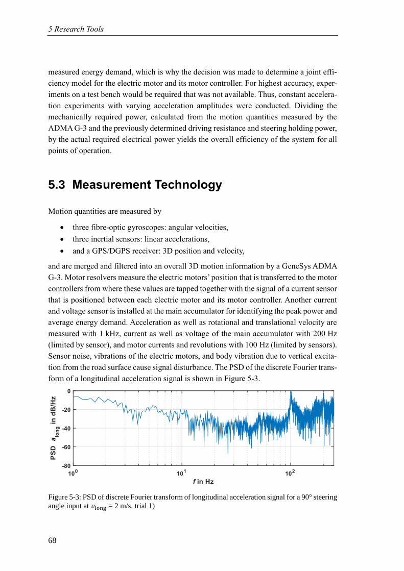
5 Research Tools
68
measured energy demand, which is why the decision was made to determine a joint effi-
ciency model for the electric motor and its motor controller. For highest accuracy, exper-
iments on a test bench would be required that was not available. Thus, constant accelera-
tion experiments with varying acceleration amplitudes were conducted. Dividing the
mechanically required power, calculated from the motion quantities measured by the
ADMA G-3 and the previously determined driving resistance and steering holding power,
by the actual required electrical power yields the overall efficiency of the system for all
points of operation.
5.3 Measurement Technology
Motion quantities are measured by
• three fibre-optic gyroscopes: angular velocities,
• three inertial sensors: linear accelerations,
• and a GPS/DGPS receiver: 3D position and velocity,
and are merged and filtered into an overall 3D motion information by a GeneSys ADMA
G-3. Motor resolvers measure the electric motors’ position that is transferred to the motor
controllers from where these values are tapped together with the signal of a current sensor
that is positioned between each electric motor and its motor controller. Another current
and voltage sensor is installed at the main accumulator for identifying the peak power and
average energy demand. Acceleration as well as rotational and translational velocity are
measured with 1 kHz, current as well as voltage of the main accumulator with 200 Hz
(limited by sensor), and motor currents and revolutions with 100 Hz (limited by sensors).
Sensor noise, vibrations of the electric motors, and body vibration due to vertical excita-
tion from the road surface cause signal disturbance. The PSD of the discrete Fourier trans-
form of a longitudinal acceleration signal is shown in Figure 5-3.
Figure 5-3: PSD of discrete Fourier transform of longitudinal acceleration signal for a 90° steering
angle input at 𝑣lon = 2 m/s, trial 1)
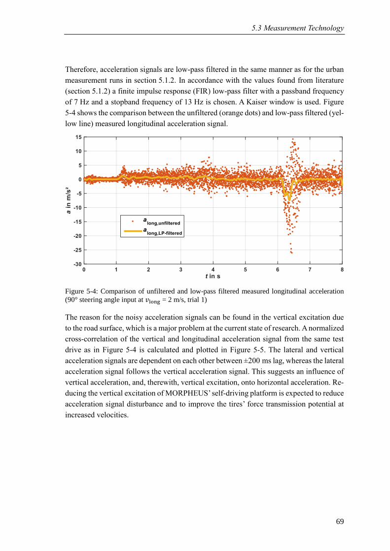
5.3 Measurement Technology
69
Therefore, acceleration signals are low-pass filtered in the same manner as for the urban
measurement runs in section 5.1.2. In accordance with the values found from literature
(section 5.1.2) a finite impulse response (FIR) low-pass filter with a passband frequency
of 7 Hz and a stopband frequency of 13 Hz is chosen. A Kaiser window is used. Figure
5-4 shows the comparison between the unfiltered (orange dots) and low-pass filtered (yel-
low line) measured longitudinal acceleration signal.
Figure 5-4: Comparison of unfiltered and low-pass filtered measured longitudinal acceleration
(90° steering angle input at 𝑣lon = 2 m/s, trial 1)
The reason for the noisy acceleration signals can be found in the vertical excitation due
to the road surface, which is a major problem at the current state of research. A normalized
cross-correlation of the vertical and longitudinal acceleration signal from the same test
drive as in Figure 5-4 is calculated and plotted in Figure 5-5. The lateral and vertical
acceleration signals are dependent on each other between ±200 ms lag, whereas the lateral
acceleration signal follows the vertical acceleration signal. This suggests an influence of
vertical acceleration, and, therewith, vertical excitation, onto horizontal acceleration. Re-
ducing the vertical excitation of MORPHEUS’ self-driving platform is expected to reduce
acceleration signal disturbance and to improve the tires’ force transmission potential at
increased velocities.
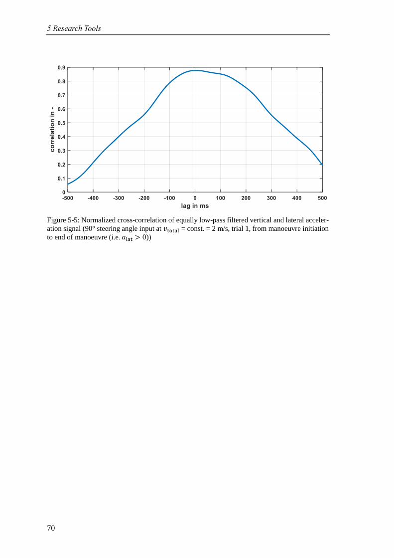
5 Research Tools
70
Figure 5-5: Normalized cross-correlation of equally low-pass filtered vertical and lateral acceler-
ation signal (90° steering angle input at 𝑣total = const. = 2 m/s, trial 1, from manoeuvre initiation
to end of manoeuvre (i.e. 𝑎lat > 0))
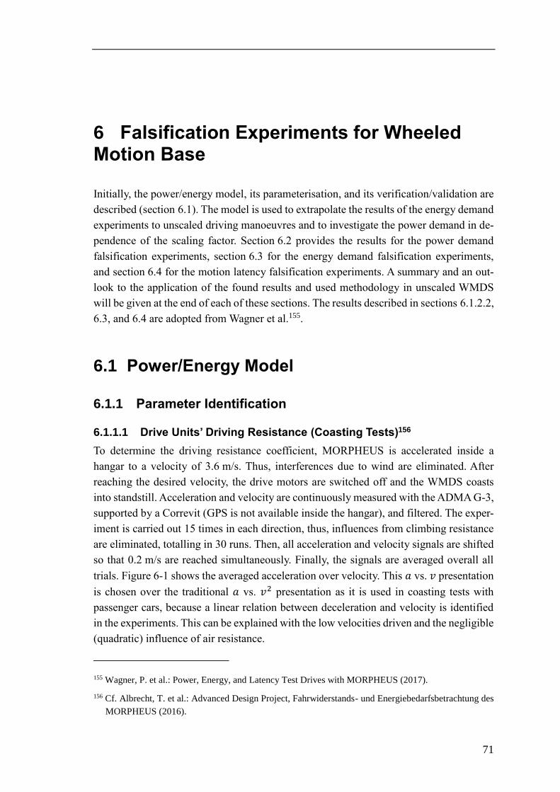
71
6 Falsification Experiments for Wheeled Motion Base
Initially, the power/energy model, its parameterisation, and its verification/validation are
described (section 6.1). The model is used to extrapolate the results of the energy demand
experiments to unscaled driving manoeuvres and to investigate the power demand in de-
pendence of the scaling factor. Section 6.2 provides the results for the power demand
falsification experiments, section 6.3 for the energy demand falsification experiments,
and section 6.4 for the motion latency falsification experiments. A summary and an out-
look to the application of the found results and used methodology in unscaled WMDS
will be given at the end of each of these sections. The results described in sections 6.1.2.2,
6.3, and 6.4 are adopted from Wagner et al.155.
6.1 Power/Energy Model
6.1.1 Parameter Identification
6.1.1.1 Drive Units’ Driving Resistance (Coasting Tests)156
To determine the driving resistance coefficient, MORPHEUS is accelerated inside a
hangar to a velocity of 3.6 m/s. Thus, interferences due to wind are eliminated. After
reaching the desired velocity, the drive motors are switched off and the WMDS coasts
into standstill. Acceleration and velocity are continuously measured with the ADMA G-3,
supported by a Correvit (GPS is not available inside the hangar), and filtered. The exper-
iment is carried out 15 times in each direction, thus, influences from climbing resistance
are eliminated, totalling in 30 runs. Then, all acceleration and velocity signals are shifted
so that 0.2 m/s are reached simultaneously. Finally, the signals are averaged overall all
trials. Figure 6-1 shows the averaged acceleration over velocity. This 𝑎 vs. 𝑣 presentation
is chosen over the traditional 𝑎 vs. 𝑣2 presentation as it is used in coasting tests with
passenger cars, because a linear relation between deceleration and velocity is identified
in the experiments. This can be explained with the low velocities driven and the negligible
(quadratic) influence of air resistance.
155 Wagner, P. et al.: Power, Energy, and Latency Test Drives with MORPHEUS (2017).
156 Cf. Albrecht, T. et al.: Advanced Design Project, Fahrwiderstands- und Energiebedarfsbetrachtung des
MORPHEUS (2016).
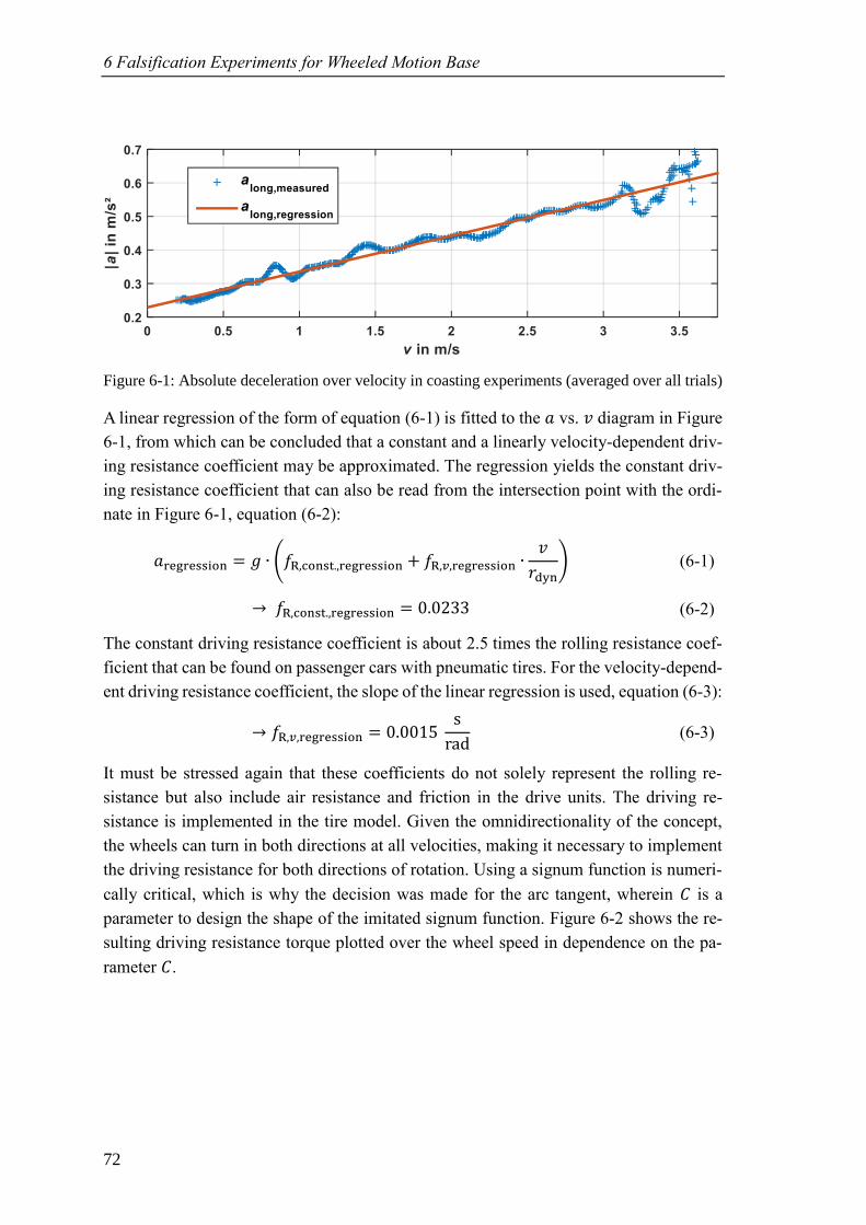
6 Falsification Experiments for Wheeled Motion Base
72
Figure 6-1: Absolute deceleration over velocity in coasting experiments (averaged over all trials)
A linear regression of the form of equation (6-1) is fitted to the 𝑎 vs. 𝑣 diagram in Figure
6-1, from which can be concluded that a constant and a linearly velocity-dependent driv-
ing resistance coefficient may be approximated. The regression yields the constant driv-
ing resistance coefficient that can also be read from the intersection point with the ordi-
nate in Figure 6-1, equation (6-2):
𝑎re ression = 𝑔 ∙ (𝑓 , onst.,re ression + 𝑓 ,𝑣,re ression ∙𝑣
dyn) (6-1)
𝑓 , onst.,re ression = 0.0233 (6-2)
The constant driving resistance coefficient is about 2.5 times the rolling resistance coef-
ficient that can be found on passenger cars with pneumatic tires. For the velocity-depend-
ent driving resistance coefficient, the slope of the linear regression is used, equation (6-3):
𝑓 ,𝑣,re ression = 0.0015 s
r d (6-3)
It must be stressed again that these coefficients do not solely represent the rolling re-
sistance but also include air resistance and friction in the drive units. The driving re-
sistance is implemented in the tire model. Given the omnidirectionality of the concept,
the wheels can turn in both directions at all velocities, making it necessary to implement
the driving resistance for both directions of rotation. Using a signum function is numeri-
cally critical, which is why the decision was made for the arc tangent, wherein is a
parameter to design the shape of the imitated signum function. Figure 6-2 shows the re-
sulting driving resistance torque plotted over the wheel speed in dependence on the pa-
rameter .
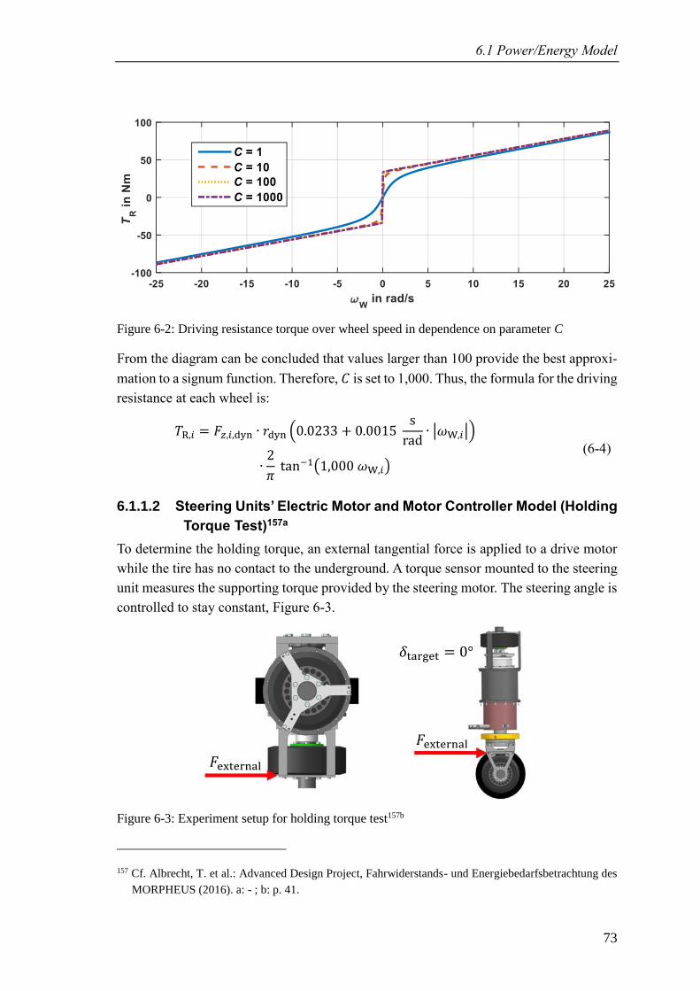
6.1 Power/Energy Model
73
Figure 6-2: Driving resistance torque over wheel speed in dependence on parameter C
From the diagram can be concluded that values larger than 100 provide the best approxi-
mation to a signum function. Therefore, is set to 1,000. Thus, the formula for the driving
resistance at each wheel is:
𝑇 ,𝑖 = ,𝑖,dyn ∙ dyn (0.0233 + 0.0015 s
r d∙ |𝜔 ,𝑖|)
∙2
𝜋 t n−1(1,000 𝜔 ,𝑖)
(6-4)
6.1.1.2 Steering Units’ Electric Motor and Motor Controller Model (Holding
Torque Test)157a
To determine the holding torque, an external tangential force is applied to a drive motor
while the tire has no contact to the underground. A torque sensor mounted to the steering
unit measures the supporting torque provided by the steering motor. The steering angle is
controlled to stay constant, Figure 6-3.
Figure 6-3: Experiment setup for holding torque test157b
157 Cf. Albrecht, T. et al.: Advanced Design Project, Fahrwiderstands- und Energiebedarfsbetrachtung des
MORPHEUS (2016). a: - ; b: p. 41.
𝛿tar et = 0°
external external
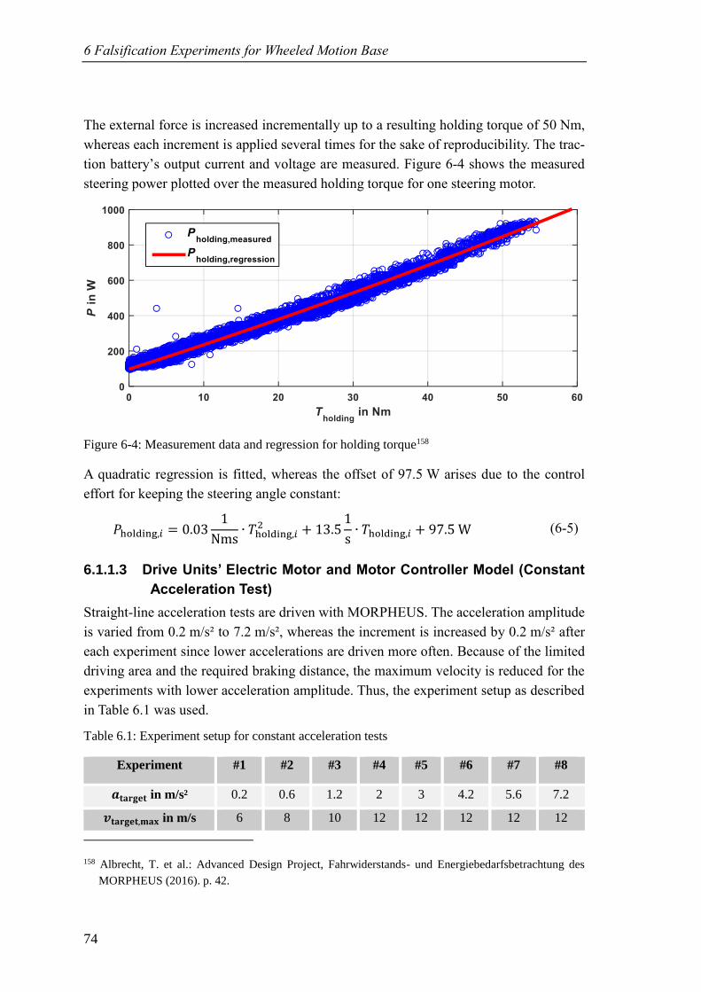
6 Falsification Experiments for Wheeled Motion Base
74
The external force is increased incrementally up to a resulting holding torque of 50 Nm,
whereas each increment is applied several times for the sake of reproducibility. The trac-
tion battery’s output current and voltage are measured. Figure 6-4 shows the measured
steering power plotted over the measured holding torque for one steering motor.
Figure 6-4: Measurement data and regression for holding torque158
A quadratic regression is fitted, whereas the offset of 97.5 W arises due to the control
effort for keeping the steering angle constant:
𝑃holdin ,𝑖 = 0.031
Nms∙ 𝑇holdin ,𝑖
2 + 13.51
s∙ 𝑇holdin ,𝑖 + 97.5 W (6-5)
6.1.1.3 Drive Units’ Electric Motor and Motor Controller Model (Constant
Acceleration Test)
Straight-line acceleration tests are driven with MORPHEUS. The acceleration amplitude
is varied from 0.2 m/s² to 7.2 m/s², whereas the increment is increased by 0.2 m/s² after
each experiment since lower accelerations are driven more often. Because of the limited
driving area and the required braking distance, the maximum velocity is reduced for the
experiments with lower acceleration amplitude. Thus, the experiment setup as described
in Table 6.1 was used.
Table 6.1: Experiment setup for constant acceleration tests
Experiment #1 #2 #3 #4 #5 #6 #7 #8
𝒂𝐭𝐚𝐫𝐠𝐞𝐭 in m/s² 0.2 0.6 1.2 2 3 4.2 5.6 7.2
𝒗𝐭𝐚𝐫𝐠𝐞𝐭,𝐦𝐚𝐱 in m/s 6 8 10 12 12 12 12 12
158 Albrecht, T. et al.: Advanced Design Project, Fahrwiderstands- und Energiebedarfsbetrachtung des
MORPHEUS (2016). p. 42.
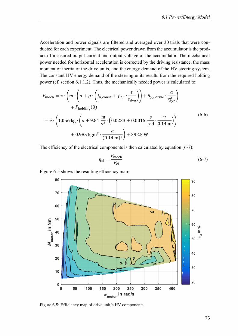
6.1 Power/Energy Model
75
Acceleration and power signals are filtered and averaged over 30 trials that were con-
ducted for each experiment. The electrical power drawn from the accumulator is the prod-
uct of measured output current and output voltage of the accumulator. The mechanical
power needed for horizontal acceleration is corrected by the driving resistance, the mass
moment of inertia of the drive units, and the energy demand of the HV steering system.
The constant HV energy demand of the steering units results from the required holding
power (cf. section 6.1.1.2). Thus, the mechanically needed power is calculated to:
𝑃me h = 𝑣 ∙ (𝑚 ∙ (𝑎 + 𝑔 ∙ (𝑓 , onst. + 𝑓 ,𝑣 ∙𝑣
dyn)) + 𝜃𝑦𝑦,dri e ∙
𝑎
dyn2 )
+ 𝑃holdin (0)
= 𝑣 ∙ (1,056 kg ∙ (𝑎 + 9.81 m
s2∙ (0.0233 + 0.0015
s
r d∙
𝑣
0.14 m))
+ 0.985 kgm2 ∙𝑎
(0.14 m)2) + 292.5 W
(6-6)
The efficiency of the electrical components is then calculated by equation (6-7):
𝜂el =𝑃me h
𝑃el (6-7)
Figure 6-5 shows the resulting efficiency map:
Figure 6-5: Efficiency map of drive unit’s HV components
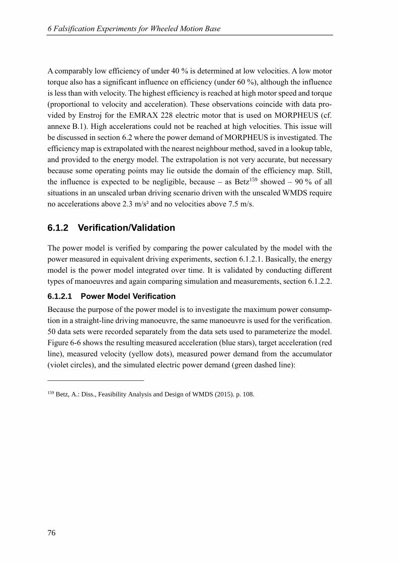
6 Falsification Experiments for Wheeled Motion Base
76
A comparably low efficiency of under 40 % is determined at low velocities. A low motor
torque also has a significant influence on efficiency (under 60 %), although the influence
is less than with velocity. The highest efficiency is reached at high motor speed and torque
(proportional to velocity and acceleration). These observations coincide with data pro-
vided by Enstroj for the EMRAX 228 electric motor that is used on MORPHEUS (cf.
annexe B.1). High accelerations could not be reached at high velocities. This issue will
be discussed in section 6.2 where the power demand of MORPHEUS is investigated. The
efficiency map is extrapolated with the nearest neighbour method, saved in a lookup table,
and provided to the energy model. The extrapolation is not very accurate, but necessary
because some operating points may lie outside the domain of the efficiency map. Still,
the influence is expected to be negligible, because – as Betz159 showed – 90 % of all
situations in an unscaled urban driving scenario driven with the unscaled WMDS require
no accelerations above 2.3 m/s² and no velocities above 7.5 m/s.
6.1.2 Verification/Validation
The power model is verified by comparing the power calculated by the model with the
power measured in equivalent driving experiments, section 6.1.2.1. Basically, the energy
model is the power model integrated over time. It is validated by conducting different
types of manoeuvres and again comparing simulation and measurements, section 6.1.2.2.
6.1.2.1 Power Model Verification
Because the purpose of the power model is to investigate the maximum power consump-
tion in a straight-line driving manoeuvre, the same manoeuvre is used for the verification.
50 data sets were recorded separately from the data sets used to parameterize the model.
Figure 6-6 shows the resulting measured acceleration (blue stars), target acceleration (red
line), measured velocity (yellow dots), measured power demand from the accumulator
(violet circles), and the simulated electric power demand (green dashed line):
159 Betz, A.: Diss., Feasibility Analysis and Design of WMDS (2015). p. 108.
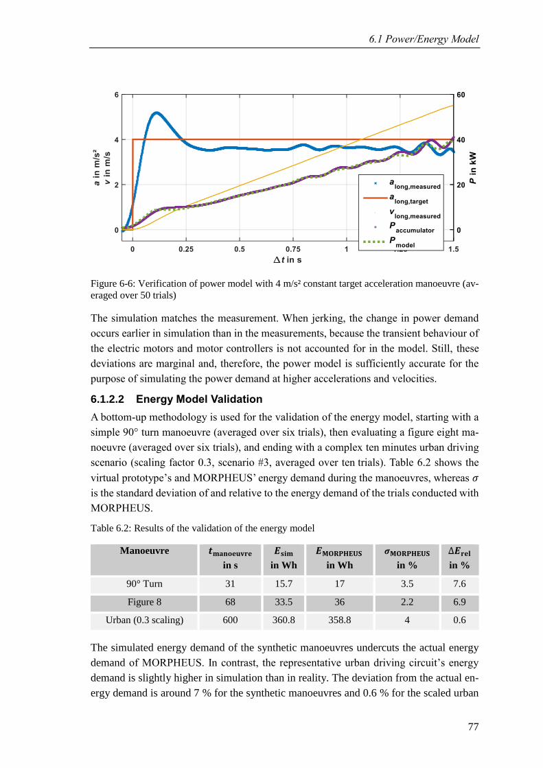
6.1 Power/Energy Model
77
Figure 6-6: Verification of power model with 4 m/s² constant target acceleration manoeuvre (av-
eraged over 50 trials)
The simulation matches the measurement. When jerking, the change in power demand
occurs earlier in simulation than in the measurements, because the transient behaviour of
the electric motors and motor controllers is not accounted for in the model. Still, these
deviations are marginal and, therefore, the power model is sufficiently accurate for the
purpose of simulating the power demand at higher accelerations and velocities.
6.1.2.2 Energy Model Validation
A bottom-up methodology is used for the validation of the energy model, starting with a
simple 90° turn manoeuvre (averaged over six trials), then evaluating a figure eight ma-
noeuvre (averaged over six trials), and ending with a complex ten minutes urban driving
scenario (scaling factor 0.3, scenario #3, averaged over ten trials). Table 6.2 shows the
virtual prototype’s and MORPHEUS’ energy demand during the manoeuvres, whereas 𝜎
is the standard deviation of and relative to the energy demand of the trials conducted with
MORPHEUS.
Table 6.2: Results of the validation of the energy model
Manoeuvre 𝒕𝐦𝐚𝐧𝐨𝐞𝐮𝐯𝐫𝐞
in s
𝑬𝐬𝐢𝐦
in Wh
𝑬𝐌𝐎𝐑𝐏𝐇𝐄𝐔𝐒
in Wh
𝝈𝐌𝐎𝐑𝐏𝐇𝐄𝐔𝐒
in %
∆𝑬𝐫𝐞𝐥
in %
90° Turn 31 15.7 17 3.5 7.6
Figure 8 68 33.5 36 2.2 6.9
Urban (0.3 scaling) 600 360.8 358.8 4 0.6
The simulated energy demand of the synthetic manoeuvres undercuts the actual energy
demand of MORPHEUS. In contrast, the representative urban driving circuit’s energy
demand is slightly higher in simulation than in reality. The deviation from the actual en-
ergy demand is around 7 % for the synthetic manoeuvres and 0.6 % for the scaled urban
6 Falsification Experiments for Wheeled Motion Base
78
driving circuit. Thus, the energy model may be used for estimating the platform’s un-
scaled energy demand.
6.1.3 Adaption to Full-Scale WMDS
The power/energy model can be used for the full-scale WMDS, too, although a re-param-
eterisation will be required, because components like tires, bearings, electric motors, mo-
tor controllers, etc. will be changed. Furthermore, the influence of air resistance will be-
come more significant as the maximum velocity will be increased. Therefore, the driving
resistance should be modelled with a quadratic dependence on wheel speed. Nevertheless,
the model structure as well as the methodology for parameterisation and verification can
be kept. Therefore, an updated power/energy model for a full-scale WMDS can be made
available in two or three working days, as soon as a working prototype is available. Then,
the investigation of the falsification aspects can be conducted in the same manner as de-
scribed within this thesis.
6.2 Power Demand
As previously stressed, the maximum velocity of MORPHEUS and the accumulator’s
output power are insufficient to conduct experiments for all occurring velocity amplitudes
with scaling factors of up to 1. Therefore, the power/energy model is used to calculate the
required mechanical and electrical power for representing the maximum acceleration and
velocity amplitude of the corresponding scaling factor, equation (6-8):
𝑃el = (𝑃 + 𝑃𝜃𝑦𝑦 + 𝑃steerin )⏟ 𝑃m ch
∙ 𝜂el
= (((𝑎 + 9.81 m
s2∙ (0.0233 + 0.0015
s
r d∙ 𝜔 ))
∙ 1,056 kg + 0.985 kgm2 ∙𝑎
(0.14 m)2) ∙ 𝜔 ∙ 0.14 m
+ 292.5 W) ∙ 𝜂el(𝜔 , 𝑇me h)
(6-8)
Figure 6-7 shows the result for this calculation, depicting the maximum output power of
the accumulator (blue line) as well as the mechanically (yellow dotted line, including all
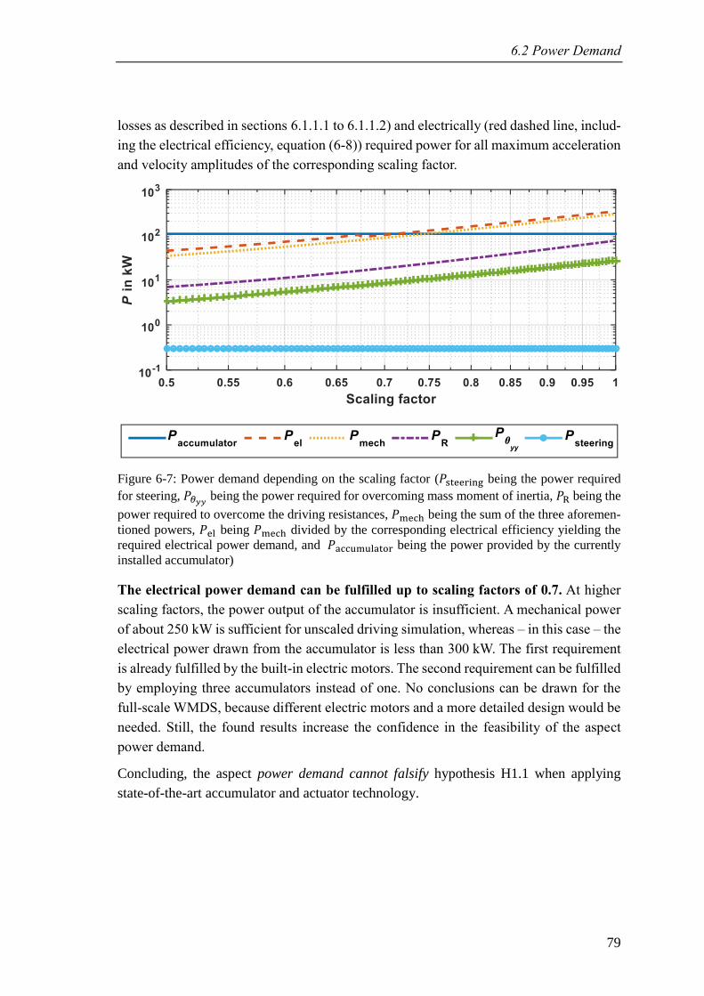
6.2 Power Demand
79
losses as described in sections 6.1.1.1 to 6.1.1.2) and electrically (red dashed line, includ-
ing the electrical efficiency, equation (6-8)) required power for all maximum acceleration
and velocity amplitudes of the corresponding scaling factor.
Figure 6-7: Power demand depending on the scaling factor (𝑃steerin being the power required
for steering, 𝑃𝜃𝑦𝑦 being the power required for overcoming mass moment of inertia, 𝑃 being the
power required to overcome the driving resistances, 𝑃me h being the sum of the three aforemen-
tioned powers, 𝑃el being 𝑃me h divided by the corresponding electrical efficiency yielding the
required electrical power demand, and 𝑃a umulator being the power provided by the currently
installed accumulator)
The electrical power demand can be fulfilled up to scaling factors of 0.7. At higher
scaling factors, the power output of the accumulator is insufficient. A mechanical power
of about 250 kW is sufficient for unscaled driving simulation, whereas – in this case – the
electrical power drawn from the accumulator is less than 300 kW. The first requirement
is already fulfilled by the built-in electric motors. The second requirement can be fulfilled
by employing three accumulators instead of one. No conclusions can be drawn for the
full-scale WMDS, because different electric motors and a more detailed design would be
needed. Still, the found results increase the confidence in the feasibility of the aspect
power demand.
Concluding, the aspect power demand cannot falsify hypothesis H1.1 when applying
state-of-the-art accumulator and actuator technology.
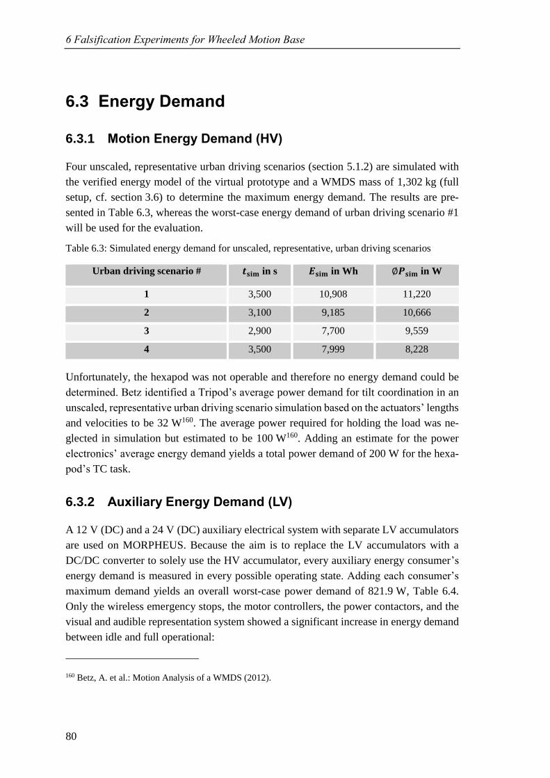
6 Falsification Experiments for Wheeled Motion Base
80
6.3 Energy Demand
6.3.1 Motion Energy Demand (HV)
Four unscaled, representative urban driving scenarios (section 5.1.2) are simulated with
the verified energy model of the virtual prototype and a WMDS mass of 1,302 kg (full
setup, cf. section 3.6) to determine the maximum energy demand. The results are pre-
sented in Table 6.3, whereas the worst-case energy demand of urban driving scenario #1
will be used for the evaluation.
Table 6.3: Simulated energy demand for unscaled, representative, urban driving scenarios
Urban driving scenario # 𝒕𝐬𝐢𝐦 in s 𝑬𝐬𝐢𝐦 in Wh ∅𝑷𝐬𝐢𝐦 in W
1 3,500 10,908 11,220
2 3,100 9,185 10,666
3 2,900 7,700 9,559
4 3,500 7,999 8,228
Unfortunately, the hexapod was not operable and therefore no energy demand could be
determined. Betz identified a Tripod’s average power demand for tilt coordination in an
unscaled, representative urban driving scenario simulation based on the actuators’ lengths
and velocities to be 32 W160. The average power required for holding the load was ne-
glected in simulation but estimated to be 100 W160. Adding an estimate for the power
electronics’ average energy demand yields a total power demand of 200 W for the hexa-
pod’s TC task.
6.3.2 Auxiliary Energy Demand (LV)
A 12 V (DC) and a 24 V (DC) auxiliary electrical system with separate LV accumulators
are used on MORPHEUS. Because the aim is to replace the LV accumulators with a
DC/DC converter to solely use the HV accumulator, every auxiliary energy consumer’s
energy demand is measured in every possible operating state. Adding each consumer’s
maximum demand yields an overall worst-case power demand of 821.9 W, Table 6.4.
Only the wireless emergency stops, the motor controllers, the power contactors, and the
visual and audible representation system showed a significant increase in energy demand
between idle and full operational:
160 Betz, A. et al.: Motion Analysis of a WMDS (2012).
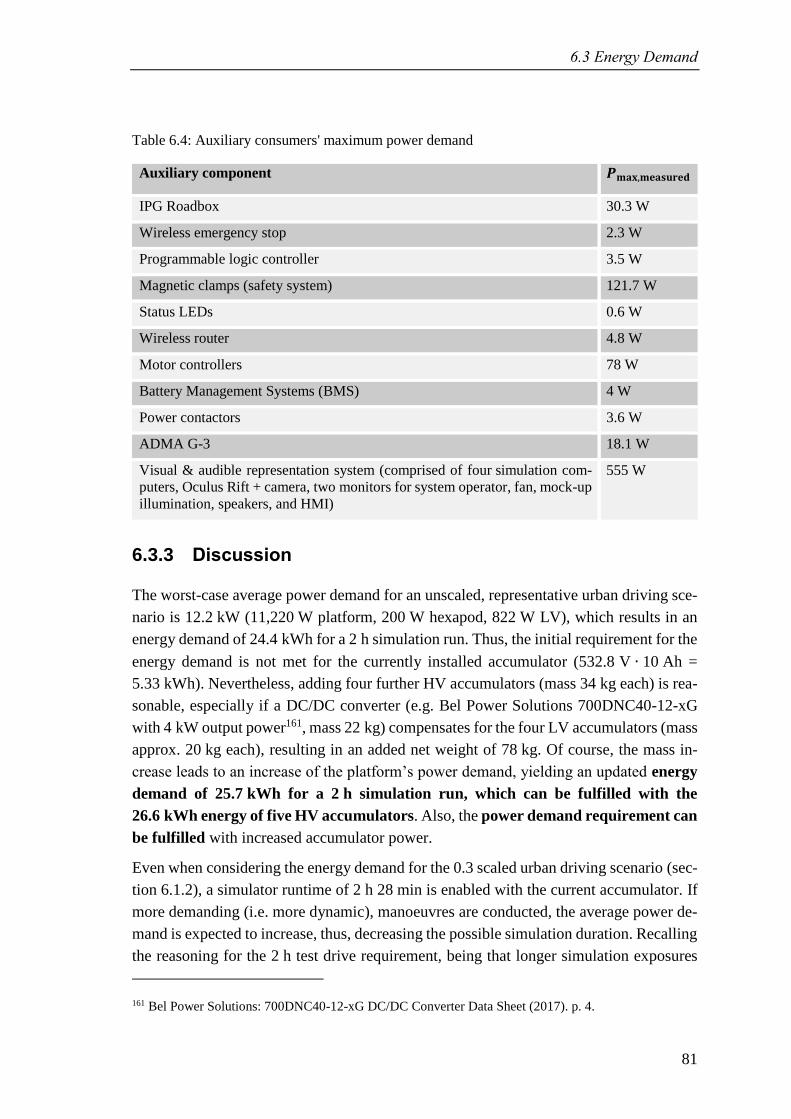
6.3 Energy Demand
81
Table 6.4: Auxiliary consumers' maximum power demand
Auxiliary component 𝑷𝐦𝐚𝐱,𝐦𝐞𝐚𝐬𝐮𝐫𝐞𝐝
IPG Roadbox 30.3 W
Wireless emergency stop 2.3 W
Programmable logic controller 3.5 W
Magnetic clamps (safety system) 121.7 W
Status LEDs 0.6 W
Wireless router 4.8 W
Motor controllers 78 W
Battery Management Systems (BMS) 4 W
Power contactors 3.6 W
ADMA G-3 18.1 W
Visual & audible representation system (comprised of four simulation com-
puters, Oculus Rift + camera, two monitors for system operator, fan, mock-up
illumination, speakers, and HMI)
555 W
6.3.3 Discussion
The worst-case average power demand for an unscaled, representative urban driving sce-
nario is 12.2 kW (11,220 W platform, 200 W hexapod, 822 W LV), which results in an
energy demand of 24.4 kWh for a 2 h simulation run. Thus, the initial requirement for the
energy demand is not met for the currently installed accumulator (532.8 V ∙ 10 Ah =
5.33 kWh). Nevertheless, adding four further HV accumulators (mass 34 kg each) is rea-
sonable, especially if a DC/DC converter (e.g. Bel Power Solutions 700DNC40-12-xG
with 4 kW output power161, mass 22 kg) compensates for the four LV accumulators (mass
approx. 20 kg each), resulting in an added net weight of 78 kg. Of course, the mass in-
crease leads to an increase of the platform’s power demand, yielding an updated energy
demand of 25.7 kWh for a 2 h simulation run, which can be fulfilled with the
26.6 kWh energy of five HV accumulators. Also, the power demand requirement can
be fulfilled with increased accumulator power.
Even when considering the energy demand for the 0.3 scaled urban driving scenario (sec-
tion 6.1.2), a simulator runtime of 2 h 28 min is enabled with the current accumulator. If
more demanding (i.e. more dynamic), manoeuvres are conducted, the average power de-
mand is expected to increase, thus, decreasing the possible simulation duration. Recalling
the reasoning for the 2 h test drive requirement, being that longer simulation exposures
161 Bel Power Solutions: 700DNC40-12-xG DC/DC Converter Data Sheet (2017). p. 4.
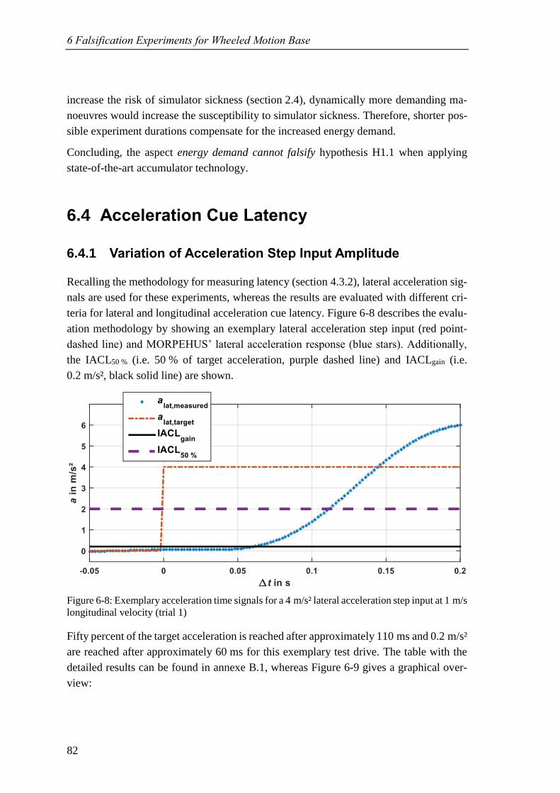
6 Falsification Experiments for Wheeled Motion Base
82
increase the risk of simulator sickness (section 2.4), dynamically more demanding ma-
noeuvres would increase the susceptibility to simulator sickness. Therefore, shorter pos-
sible experiment durations compensate for the increased energy demand.
Concluding, the aspect energy demand cannot falsify hypothesis H1.1 when applying
state-of-the-art accumulator technology.
6.4 Acceleration Cue Latency
6.4.1 Variation of Acceleration Step Input Amplitude
Recalling the methodology for measuring latency (section 4.3.2), lateral acceleration sig-
nals are used for these experiments, whereas the results are evaluated with different cri-
teria for lateral and longitudinal acceleration cue latency. Figure 6-8 describes the evalu-
ation methodology by showing an exemplary lateral acceleration step input (red point-
dashed line) and MORPEHUS’ lateral acceleration response (blue stars). Additionally,
the IACL50 % (i.e. 50 % of target acceleration, purple dashed line) and IACLgain (i.e.
0.2 m/s², black solid line) are shown.
Figure 6-8: Exemplary acceleration time signals for a 4 m/s² lateral acceleration step input at 1 m/s
longitudinal velocity (trial 1)
Fifty percent of the target acceleration is reached after approximately 110 ms and 0.2 m/s²
are reached after approximately 60 ms for this exemplary test drive. The table with the
detailed results can be found in annexe B.1, whereas Figure 6-9 gives a graphical over-
view:
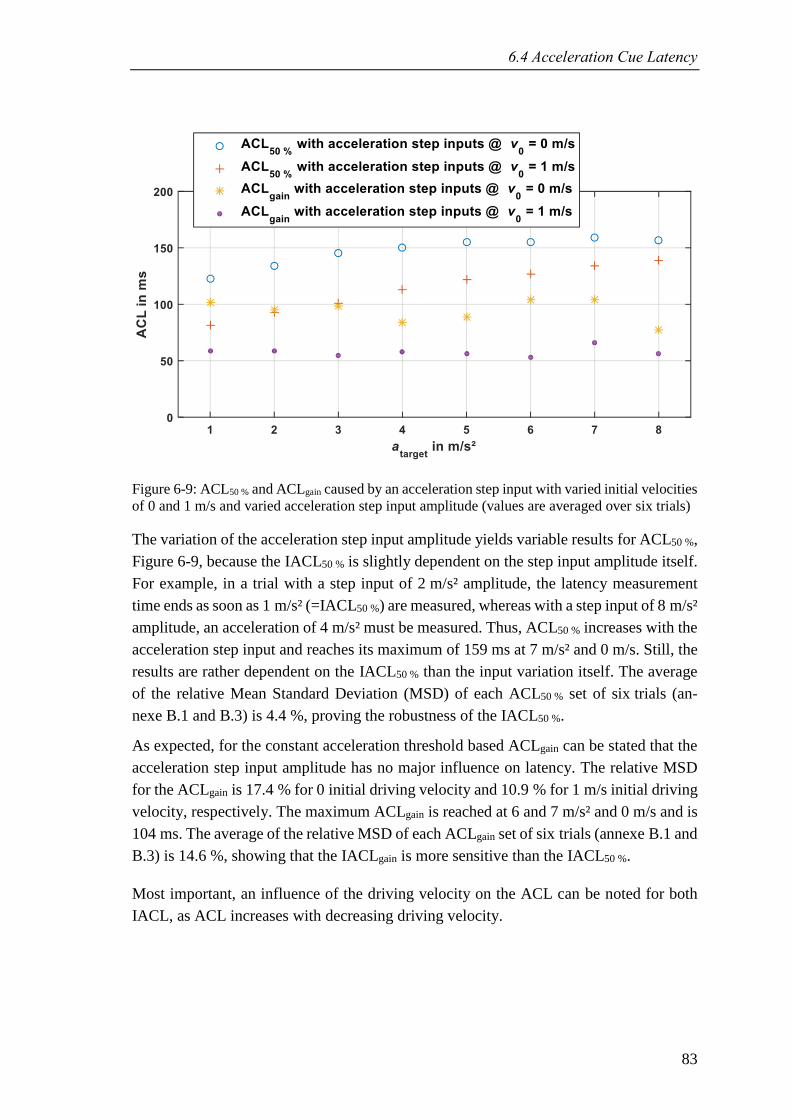
6.4 Acceleration Cue Latency
83
Figure 6-9: ACL50 % and ACLgain caused by an acceleration step input with varied initial velocities
of 0 and 1 m/s and varied acceleration step input amplitude (values are averaged over six trials)
The variation of the acceleration step input amplitude yields variable results for ACL50 %,
Figure 6-9, because the IACL50 % is slightly dependent on the step input amplitude itself.
For example, in a trial with a step input of 2 m/s² amplitude, the latency measurement
time ends as soon as 1 m/s² (=IACL50 %) are measured, whereas with a step input of 8 m/s²
amplitude, an acceleration of 4 m/s² must be measured. Thus, ACL50 % increases with the
acceleration step input and reaches its maximum of 159 ms at 7 m/s² and 0 m/s. Still, the
results are rather dependent on the IACL50 % than the input variation itself. The average
of the relative Mean Standard Deviation (MSD) of each ACL50 % set of six trials (an-
nexe B.1 and B.3) is 4.4 %, proving the robustness of the IACL50 %.
As expected, for the constant acceleration threshold based ACLgain can be stated that the
acceleration step input amplitude has no major influence on latency. The relative MSD
for the ACLgain is 17.4 % for 0 initial driving velocity and 10.9 % for 1 m/s initial driving
velocity, respectively. The maximum ACLgain is reached at 6 and 7 m/s² and 0 m/s and is
104 ms. The average of the relative MSD of each ACLgain set of six trials (annexe B.1 and
B.3) is 14.6 %, showing that the IACLgain is more sensitive than the IACL50 %.
Most important, an influence of the driving velocity on the ACL can be noted for both
IACL, as ACL increases with decreasing driving velocity.
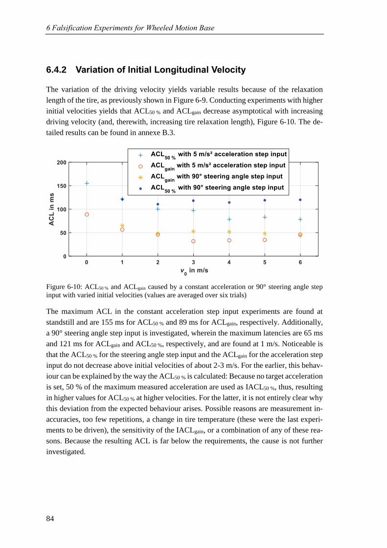
6 Falsification Experiments for Wheeled Motion Base
84
6.4.2 Variation of Initial Longitudinal Velocity
The variation of the driving velocity yields variable results because of the relaxation
length of the tire, as previously shown in Figure 6-9. Conducting experiments with higher
initial velocities yields that ACL50 % and ACLgain decrease asymptotical with increasing
driving velocity (and, therewith, increasing tire relaxation length), Figure 6-10. The de-
tailed results can be found in annexe B.3.
Figure 6-10: ACL50 % and ACLgain caused by a constant acceleration or 90° steering angle step
input with varied initial velocities (values are averaged over six trials)
The maximum ACL in the constant acceleration step input experiments are found at
standstill and are 155 ms for ACL50 % and 89 ms for ACLgain, respectively. Additionally,
a 90° steering angle step input is investigated, wherein the maximum latencies are 65 ms
and 121 ms for ACLgain and ACL50 %, respectively, and are found at 1 m/s. Noticeable is
that the ACL50 % for the steering angle step input and the ACLgain for the acceleration step
input do not decrease above initial velocities of about 2-3 m/s. For the earlier, this behav-
iour can be explained by the way the ACL50 % is calculated: Because no target acceleration
is set, 50 % of the maximum measured acceleration are used as IACL50 %, thus, resulting
in higher values for ACL50 % at higher velocities. For the latter, it is not entirely clear why
this deviation from the expected behaviour arises. Possible reasons are measurement in-
accuracies, too few repetitions, a change in tire temperature (these were the last experi-
ments to be driven), the sensitivity of the IACLgain, or a combination of any of these rea-
sons. Because the resulting ACL is far below the requirements, the cause is not further
investigated.
6.4 Acceleration Cue Latency
85
6.4.3 Discussion
Two influencing factors (initial velocity, acceleration step input amplitude) and two con-
trol input methods (acceleration step input, steering angle step input) were researched. It
was shown that the acceleration step input amplitude only affects ACL50 %, which is be-
cause IACL50 % is proportional to the acceleration step input amplitude. ACLgain showed
no sensitivity on the acceleration step input (Figure 6-9). Therefore, latency itself is not
dependent on the acceleration step input amplitude. The initial velocity, however, does
have a major influence: Increasing the driving velocity decreases ACL because of the
tires’ relaxation length. This effect is very distinctive at low speeds (Figure 6-9 and Figure
6-10). The differences between the acceleration and steering angle step input are marginal
(Figure 6-10), so that the control method seems to have no significant influence on the
acceleration cue latency.
The IACL50 % proved to yield very reproducible values for ACL50 %, whereas the IACLgain
yielded less reproducible results. This is partly caused by the resolution of 2 ms of the
time signal, but also by signal disturbance, whose influence is greater on signals with low
amplitudes (IACLgain < IACL50 % for target amplitudes above 0.4 m/s²). The require-
ments of staying below 135 ms for ACL50 % and 100 ms for ACLgain, respectively, are
not met (ACL50 %,max = 159 ms, ACLgain,max = 104 ms). However, for driving velocities
of 1 m/s and higher, ACL50 %,max is 139 ms and ACLgain,max is 66 ms. Furthermore, the
requirement for ACL50 % is set by an electric car with a controller that is optimized for
instantaneous acceleration. Standard electric cars (e.g. Tesla Model S) need about 250 ms
for providing 50 % of the target acceleration.
No direct assessment can be derived for the full-scale WMDS. However, if the novel
control approach of keeping the WMDS in motion is implemented and if the steering
power is increased appropriately (considering moment of inertia, wheel load, tire width,
and tire-road-friction coefficient), the latency requirements can be fulfilled by state-of-
the-art technology for full-scale WMDS, too.
Concluding, the aspect of motion cue latency cannot falsify hypothesis H1.1, considering
the average relative MSD of 14.6 % for ACLgain measurements, the restrictive require-
ment for ACL50 %, and the control approach to keep the simulator in motion at any time
so that the driving velocity will never become 0.

87
7 Safety Architecture
A safety architecture is defined as a “set of elements and their interaction to fulfil the
safety requirements”162. These safety requirements (also called safety goals) have been
established for the WMDS prototype MORPHEUS and its unique design. The results of
the following risk assessment cannot directly be transferred onto any DS or even the full-
scale WMDS. Nevertheless, the risk is assessed for a specific system topology whereas
the components are generic. Thus, the assessment is independent of specific components
and the established safety requirements are valid for the specified architecture and there-
with all instances derived from this architecture. For architectural design changes, meth-
ods for adapting an existing risk assessment exist. The specific results for MORPHEUS
will be adapted towards a more general application of a full-scale WMDS in section 7.4.
Of course, the quality of the risk analysis and evaluation strongly depends on the expertise
of the engineer conducting the analysis. The herein presented risk assessment (sec-
tions 7.1 and 7.2) has been carried out by the author who designed, built, and conducted
numerous experiments with MORPHEUS and been separately and thoroughly reviewed
by an engineer who is familiar with the system but no expert for WMDS as well as by a
team of two expert engineers who were involved in the development of MORPHEUS and
are also experienced in operating the prototype. Still, this cannot guarantee 100 % safety,
which is why a transparent and exhaustive documentation of the HARA is attached in
annexe B. Thus, false assumptions or missing failures, consequences, or situations can
easily be amended while still being able to keep most of the HARA.
Section 7.1 shows the results of the risk analysis, namely the hazard identification (sec-
tion 7.1.2) and the risk estimation (section 7.1.3). Together with section 7.2, risk evalua-
tion, the risk assessment process according to EN ISO 13849 (Figure 2-17) is completed.
A proposed safety architecture for fulfilling the formulated safety requirements is given
in section 7.3 together with an exemplary application of the architecture and an evaluation
of achieved risk reduction as well as a risk assessment of the newly introduced compo-
nents and functions.
162 ISO TC 22/SC 32 Electrical and electronic components and general system aspects: ISO 26262 (2011).
p. 14.
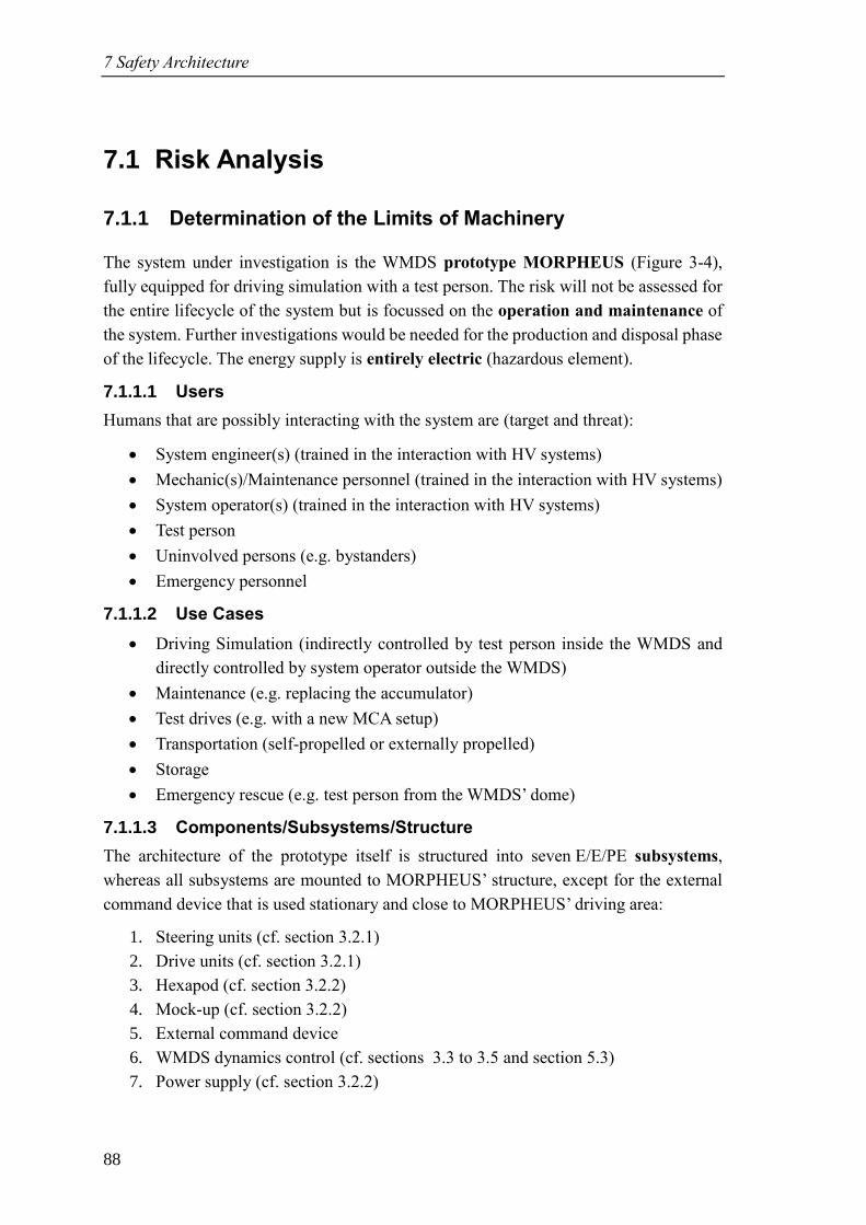
7 Safety Architecture
88
7.1 Risk Analysis
7.1.1 Determination of the Limits of Machinery
The system under investigation is the WMDS prototype MORPHEUS (Figure 3-4),
fully equipped for driving simulation with a test person. The risk will not be assessed for
the entire lifecycle of the system but is focussed on the operation and maintenance of
the system. Further investigations would be needed for the production and disposal phase
of the lifecycle. The energy supply is entirely electric (hazardous element).
7.1.1.1 Users
Humans that are possibly interacting with the system are (target and threat):
• System engineer(s) (trained in the interaction with HV systems)
• Mechanic(s)/Maintenance personnel (trained in the interaction with HV systems)
• System operator(s) (trained in the interaction with HV systems)
• Test person
• Uninvolved persons (e.g. bystanders)
• Emergency personnel
7.1.1.2 Use Cases
• Driving Simulation (indirectly controlled by test person inside the WMDS and
directly controlled by system operator outside the WMDS)
• Maintenance (e.g. replacing the accumulator)
• Test drives (e.g. with a new MCA setup)
• Transportation (self-propelled or externally propelled)
• Storage
• Emergency rescue (e.g. test person from the WMDS’ dome)
7.1.1.3 Components/Subsystems/Structure
The architecture of the prototype itself is structured into seven E/E/PE subsystems,
whereas all subsystems are mounted to MORPHEUS’ structure, except for the external
command device that is used stationary and close to MORPHEUS’ driving area:
1. Steering units (cf. section 3.2.1)
2. Drive units (cf. section 3.2.1)
3. Hexapod (cf. section 3.2.2)
4. Mock-up (cf. section 3.2.2)
5. External command device
6. WMDS dynamics control (cf. sections 3.3 to 3.5 and section 5.3)
7. Power supply (cf. section 3.2.2)
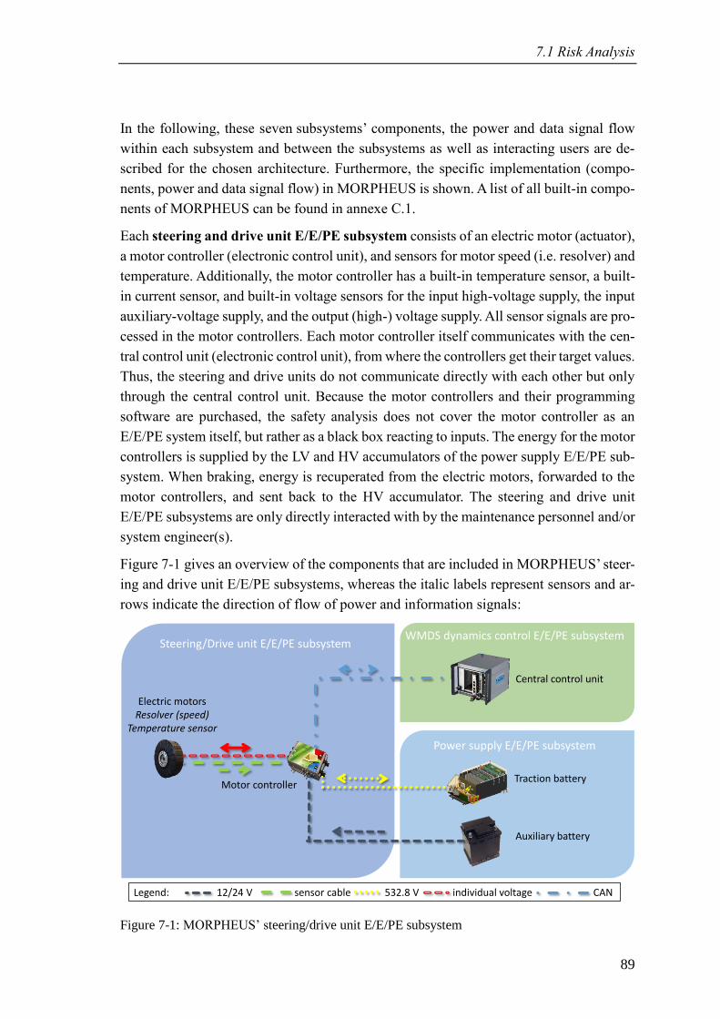
7.1 Risk Analysis
89
In the following, these seven subsystems’ components, the power and data signal flow
within each subsystem and between the subsystems as well as interacting users are de-
scribed for the chosen architecture. Furthermore, the specific implementation (compo-
nents, power and data signal flow) in MORPHEUS is shown. A list of all built-in compo-
nents of MORPHEUS can be found in annexe C.1.
Each steering and drive unit E/E/PE subsystem consists of an electric motor (actuator),
a motor controller (electronic control unit), and sensors for motor speed (i.e. resolver) and
temperature. Additionally, the motor controller has a built-in temperature sensor, a built-
in current sensor, and built-in voltage sensors for the input high-voltage supply, the input
auxiliary-voltage supply, and the output (high-) voltage supply. All sensor signals are pro-
cessed in the motor controllers. Each motor controller itself communicates with the cen-
tral control unit (electronic control unit), from where the controllers get their target values.
Thus, the steering and drive units do not communicate directly with each other but only
through the central control unit. Because the motor controllers and their programming
software are purchased, the safety analysis does not cover the motor controller as an
E/E/PE system itself, but rather as a black box reacting to inputs. The energy for the motor
controllers is supplied by the LV and HV accumulators of the power supply E/E/PE sub-
system. When braking, energy is recuperated from the electric motors, forwarded to the
motor controllers, and sent back to the HV accumulator. The steering and drive unit
E/E/PE subsystems are only directly interacted with by the maintenance personnel and/or
system engineer(s).
Figure 7-1 gives an overview of the components that are included in MORPHEUS’ steer-
ing and drive unit E/E/PE subsystems, whereas the italic labels represent sensors and ar-
rows indicate the direction of flow of power and information signals:
Figure 7-1: MORPHEUS’ steering/drive unit E/E/PE subsystem
Power supply E/E/PE subsystem
WMDS dynamics control E/E/PE subsystemSteering/Drive unit E/E/PE subsystem
Electric motorsResolver (speed)
Temperature sensor
Motor controller
Legend: 12/24 V sensor cable 532.8 V individual voltage CAN
Auxiliary battery
Traction battery
Central control unit
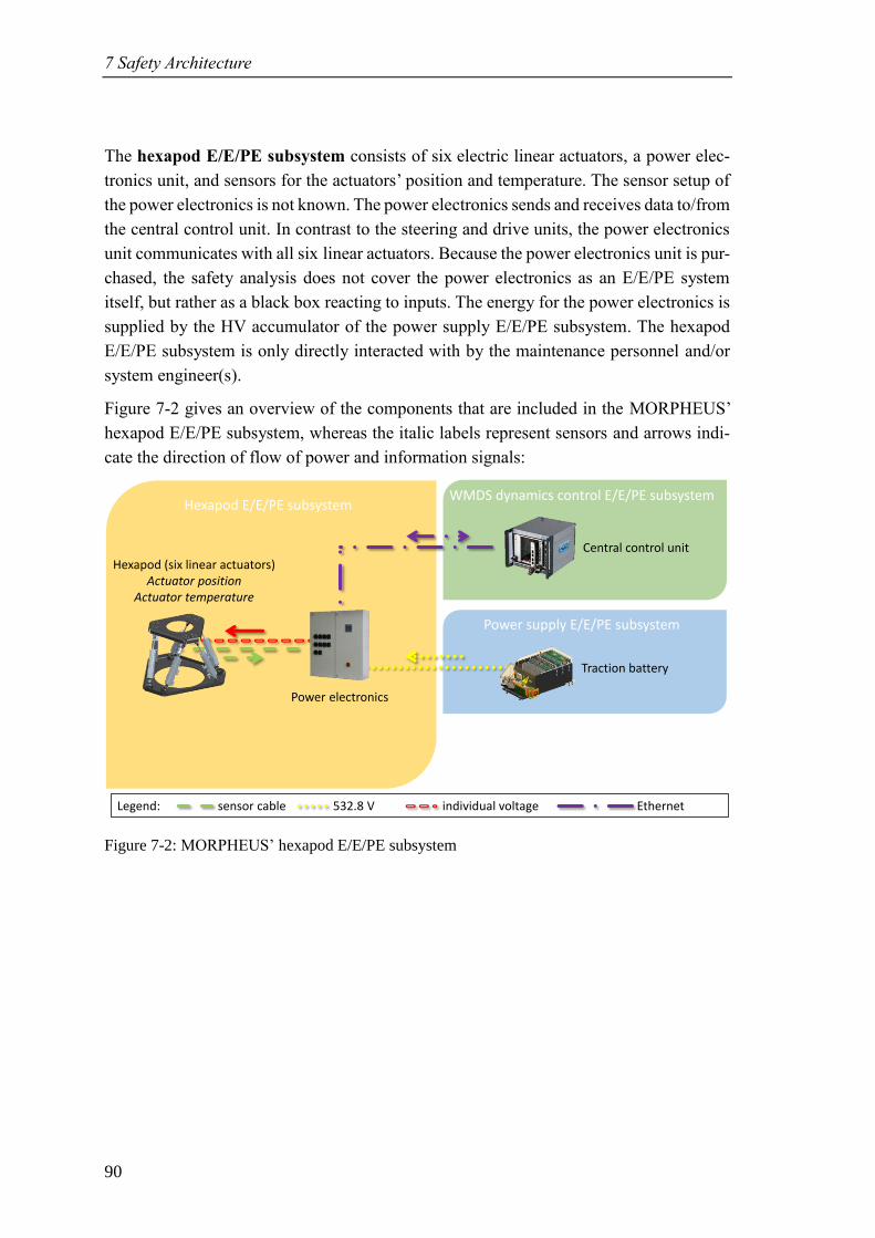
7 Safety Architecture
90
The hexapod E/E/PE subsystem consists of six electric linear actuators, a power elec-
tronics unit, and sensors for the actuators’ position and temperature. The sensor setup of
the power electronics is not known. The power electronics sends and receives data to/from
the central control unit. In contrast to the steering and drive units, the power electronics
unit communicates with all six linear actuators. Because the power electronics unit is pur-
chased, the safety analysis does not cover the power electronics as an E/E/PE system
itself, but rather as a black box reacting to inputs. The energy for the power electronics is
supplied by the HV accumulator of the power supply E/E/PE subsystem. The hexapod
E/E/PE subsystem is only directly interacted with by the maintenance personnel and/or
system engineer(s).
Figure 7-2 gives an overview of the components that are included in the MORPHEUS’
hexapod E/E/PE subsystem, whereas the italic labels represent sensors and arrows indi-
cate the direction of flow of power and information signals:
Figure 7-2: MORPHEUS’ hexapod E/E/PE subsystem
Power supply E/E/PE subsystem
WMDS dynamics control E/E/PE subsystemHexapod E/E/PE subsystem
Hexapod (six linear actuators)Actuator position
Actuator temperature
Power electronics
Traction battery
Legend: sensor cable 532.8 V individual voltage Ethernet
Central control unit
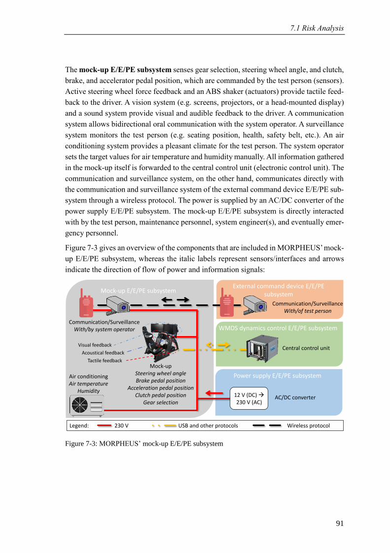
7.1 Risk Analysis
91
The mock-up E/E/PE subsystem senses gear selection, steering wheel angle, and clutch,
brake, and accelerator pedal position, which are commanded by the test person (sensors).
Active steering wheel force feedback and an ABS shaker (actuators) provide tactile feed-
back to the driver. A vision system (e.g. screens, projectors, or a head-mounted display)
and a sound system provide visual and audible feedback to the driver. A communication
system allows bidirectional oral communication with the system operator. A surveillance
system monitors the test person (e.g. seating position, health, safety belt, etc.). An air
conditioning system provides a pleasant climate for the test person. The system operator
sets the target values for air temperature and humidity manually. All information gathered
in the mock-up itself is forwarded to the central control unit (electronic control unit). The
communication and surveillance system, on the other hand, communicates directly with
the communication and surveillance system of the external command device E/E/PE sub-
system through a wireless protocol. The power is supplied by an AC/DC converter of the
power supply E/E/PE subsystem. The mock-up E/E/PE subsystem is directly interacted
with by the test person, maintenance personnel, system engineer(s), and eventually emer-
gency personnel.
Figure 7-3 gives an overview of the components that are included in MORPHEUS’ mock-
up E/E/PE subsystem, whereas the italic labels represent sensors/interfaces and arrows
indicate the direction of flow of power and information signals:
Figure 7-3: MORPHEUS’ mock-up E/E/PE subsystem
WMDS dynamics control E/E/PE subsystem
Mock-up E/E/PE subsystem
Power supply E/E/PE subsystem
Legend: 230 V USB and other protocols Wireless protocol
Tactile feedback
Visual feedback
Acoustical feedback
Communication/SurveillanceWith/by system operator
Air conditioningAir temperature
Humidity
External command device E/E/PE subsystem
AC/DC converter
Communication/SurveillanceWith/of test person
Mock-upSteering wheel angleBrake pedal position
Acceleration pedal positionClutch pedal position
Gear selection
Central control unit
12 V (DC) →230 V (AC)
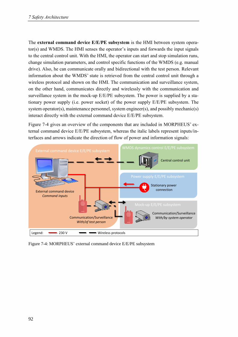
7 Safety Architecture
92
The external command device E/E/PE subsystem is the HMI between system opera-
tor(s) and WMDS. The HMI senses the operator’s inputs and forwards the input signals
to the central control unit. With the HMI, the operator can start and stop simulation runs,
change simulation parameters, and control specific functions of the WMDS (e.g. manual
drive). Also, he can communicate orally and bidirectional with the test person. Relevant
information about the WMDS’ state is retrieved from the central control unit through a
wireless protocol and shown on the HMI. The communication and surveillance system,
on the other hand, communicates directly and wirelessly with the communication and
surveillance system in the mock-up E/E/PE subsystem. The power is supplied by a sta-
tionary power supply (i.e. power socket) of the power supply E/E/PE subsystem. The
system operator(s), maintenance personnel, system engineer(s), and possibly mechanic(s)
interact directly with the external command device E/E/PE subsystem.
Figure 7-4 gives an overview of the components that are included in MORPHEUS’ ex-
ternal command device E/E/PE subsystem, whereas the italic labels represent inputs/in-
terfaces and arrows indicate the direction of flow of power and information signals:
Figure 7-4: MORPHEUS’ external command device E/E/PE subsystem
Mock-up E/E/PE subsystem
Power supply E/E/PE subsystem
External command device E/E/PE subsystemWMDS dynamics control E/E/PE subsystem
Legend: 230 V Wireless protocols
External command deviceCommand inputs
Communication/SurveillanceWith/of test person
Stationary powerconnection
Communication/SurveillanceWith/by system operator
Central control unit
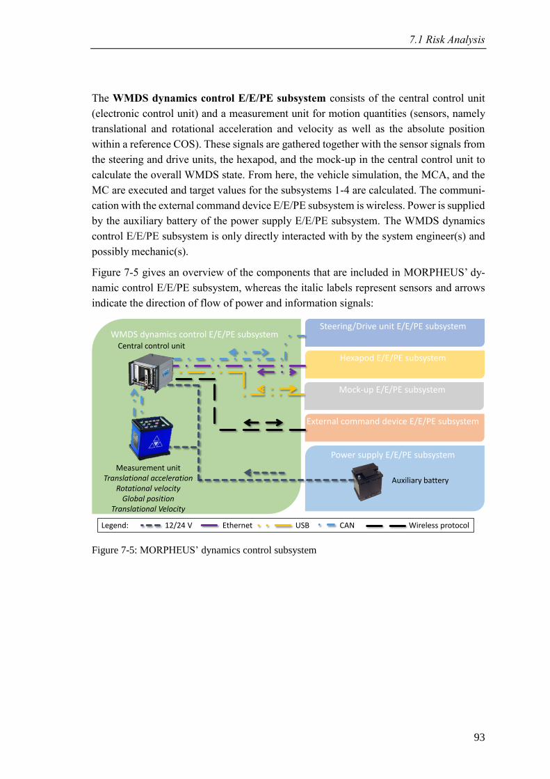
7.1 Risk Analysis
93
The WMDS dynamics control E/E/PE subsystem consists of the central control unit
(electronic control unit) and a measurement unit for motion quantities (sensors, namely
translational and rotational acceleration and velocity as well as the absolute position
within a reference COS). These signals are gathered together with the sensor signals from
the steering and drive units, the hexapod, and the mock-up in the central control unit to
calculate the overall WMDS state. From here, the vehicle simulation, the MCA, and the
MC are executed and target values for the subsystems 1-4 are calculated. The communi-
cation with the external command device E/E/PE subsystem is wireless. Power is supplied
by the auxiliary battery of the power supply E/E/PE subsystem. The WMDS dynamics
control E/E/PE subsystem is only directly interacted with by the system engineer(s) and
possibly mechanic(s).
Figure 7-5 gives an overview of the components that are included in MORPHEUS’ dy-
namic control E/E/PE subsystem, whereas the italic labels represent sensors and arrows
indicate the direction of flow of power and information signals:
Figure 7-5: MORPHEUS’ dynamics control subsystem
Power supply E/E/PE subsystem
Steering/Drive unit E/E/PE subsystemWMDS dynamics control E/E/PE subsystem
Hexapod E/E/PE subsystem
Mock-up E/E/PE subsystem
External command device E/E/PE subsystem
Central control unit
Auxiliary battery
Measurement unitTranslational acceleration
Rotational velocityGlobal position
Translational Velocity
Legend: 12/24 V Ethernet USB CAN Wireless protocol
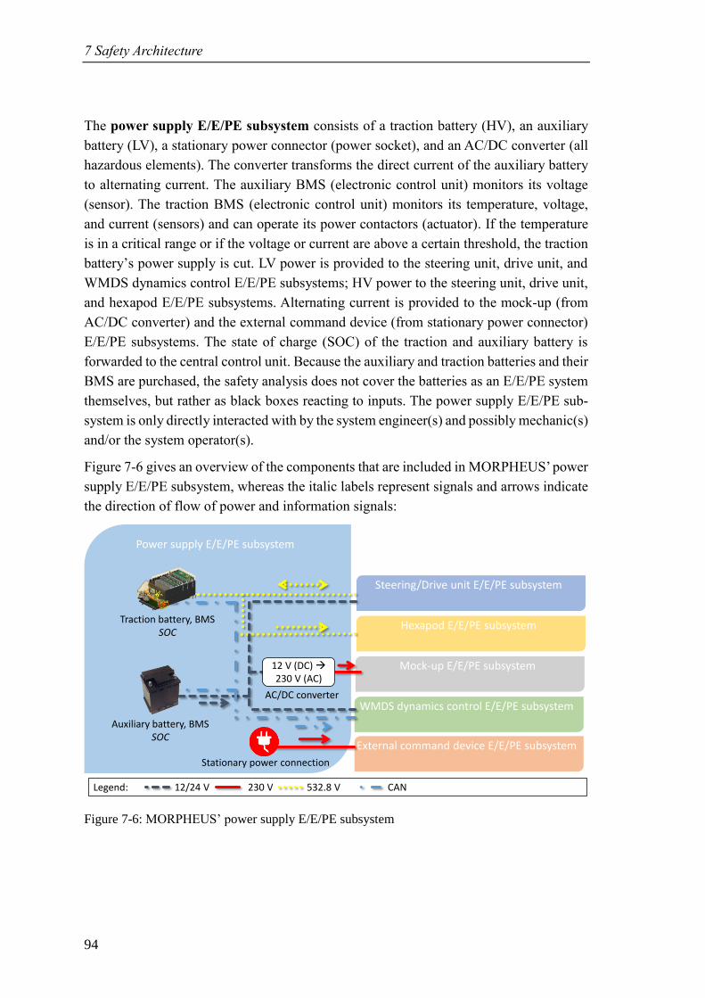
7 Safety Architecture
94
The power supply E/E/PE subsystem consists of a traction battery (HV), an auxiliary
battery (LV), a stationary power connector (power socket), and an AC/DC converter (all
hazardous elements). The converter transforms the direct current of the auxiliary battery
to alternating current. The auxiliary BMS (electronic control unit) monitors its voltage
(sensor). The traction BMS (electronic control unit) monitors its temperature, voltage,
and current (sensors) and can operate its power contactors (actuator). If the temperature
is in a critical range or if the voltage or current are above a certain threshold, the traction
battery’s power supply is cut. LV power is provided to the steering unit, drive unit, and
WMDS dynamics control E/E/PE subsystems; HV power to the steering unit, drive unit,
and hexapod E/E/PE subsystems. Alternating current is provided to the mock-up (from
AC/DC converter) and the external command device (from stationary power connector)
E/E/PE subsystems. The state of charge (SOC) of the traction and auxiliary battery is
forwarded to the central control unit. Because the auxiliary and traction batteries and their
BMS are purchased, the safety analysis does not cover the batteries as an E/E/PE system
themselves, but rather as black boxes reacting to inputs. The power supply E/E/PE sub-
system is only directly interacted with by the system engineer(s) and possibly mechanic(s)
and/or the system operator(s).
Figure 7-6 gives an overview of the components that are included in MORPHEUS’ power
supply E/E/PE subsystem, whereas the italic labels represent signals and arrows indicate
the direction of flow of power and information signals:
Figure 7-6: MORPHEUS’ power supply E/E/PE subsystem
Mock-up E/E/PE subsystem
Power supply E/E/PE subsystem
WMDS dynamics control E/E/PE subsystem
Legend: 12/24 V 230 V 532.8 V CAN
Traction battery, BMSSOC
Auxiliary battery, BMSSOC
Steering/Drive unit E/E/PE subsystem
Hexapod E/E/PE subsystem
External command device E/E/PE subsystem
12 V (DC) →230 V (AC)
Stationary power connection
AC/DC converter
7.1 Risk Analysis
95
7.1.1.4 Environment
The controlled environment, in which the system will be used, can be inside (e.g. a hall)
or outside (e.g. a vehicle dynamics test area) and includes the following conditions:
• Air temperature: -10 °C to +45 °C
• Humidity: 0 % to 85 % (condensation must be avoided)
• Direct solar radiation
• Paved undergrounds with no obstacles (objects and subjects; WMDS workspace
must be inspected before the DS may move; boundaries of the workspace must be
highlighted and monitored or cordoned off so that subjects cannot enter the work-
space) and sufficient tire-underground friction coefficient (i.e. no ice or snow)
• No rain or fog
• Low level of pollution (for E/E/PE components)
• Wind up to level 6 on the Beaufort scale (i.e. strong breeze with wind speeds up
to 49 km/h, description: “Large branches in motion; whistling heard in telegraph
wires; umbrellas used with difficulty”) resulting – at -10 °C air temperature – in a
wind chill temperature163 of -21.7 °C.
7.1.2 Hazard Identification
The methodology for the hazard identification is described in section 4.4.2. Each subsys-
tem’s components and their interconnections are investigated and – in combination with
the guidewords from the HAZOP analysis – evaluated, which failures might occur. Be-
cause the extent of the hazard list is too large to be shown within this thesis, the complete
list is attached in annexe C.2 (columns “failure” and “consequence”). At this point,
three examples are selected to demonstrate the application of the methodology.
7.1.2.1 Hazard 1.2 (Steering Unit E/E/PE Subsystem)
Failure: No or insufficient LV energy supply
Consequence: The motor controller is unable to process its signals → demanded steer-
ing angle cannot be provided → DS trajectory is uncontrollable
The LV energy supply is only connected to the motor controller in a steering unit E/E/PE
subsystem. If the voltage supplied by the LV energy supply is insufficient, the motor con-
troller automatically shuts itself down. Thus, the target values from the WMDS driving
dynamics control subsystem cannot be processed by the motor controller. The electric
steering motor cannot be controlled by the motor controller and the demanded DS trajec-
tory cannot be realized because the required steering angles cannot be adjusted.
163 Osczevski, R.; Bluestein, M.: Wind Chill Equivalent Temperature Chart (2005).
7 Safety Architecture
96
7.1.2.2 Hazard 2.8 (Drive Unit E/E/PE Subsystem)
Failure: Temperature sensor delivers no/too low/high electric motor temperature
signals
Consequence 1: Motor controller reduces maximum electric motor torque or shuts elec-
tric motor down → demanded motor torque cannot be provided → DS
trajectory is not controllable
Consequence 2: Motor controller fails to reduce electric motor torque or to shut electric
motor down → overheating of electric motor → possibly short circuit
and/or fire hazard
Here, two consequences are possible. One consequence is that, although the electric mo-
tor is operated within its specifications, the temperature sensors may send a signal to the
motor controller that the electric motor is too cold, too hot, or sends no signal at all. In all
these cases the motor controller would either reduce the maximum electric motor torque
or shut down the electric motor completely. A possible outcome would be that the de-
manded motor torque cannot be provided due to the derating or shutdown of the drive
motor.
The other possible consequence is that the electric motor is outside its specified temper-
ature range, although the temperature sensor sends an uncritical signal. Then, the motor
controller would not reduce the maximum electric motor torque or shut the motor down.
This could cause the electric motor to overheat, possibly resulting in a short circuit or a
fire hazard.
7.1.2.3 Hazard 4.20 (Mock-up E/E/PE Subsystem)
Failure: Water ingress at steering wheel
Consequence 1: Short circuit and possibly fire hazard
Consequence 2: Steering wheel force feedback actuator is unable to operate → false cues
are generated
Consequence 3: Steering wheel angle sensor is unable to operate → false cues are gen-
erated
The first consequence of water ingress at the steering wheel could be a short circuit and
possibly a fire hazard.
The second consequence is a possible malfunction of the steering wheel force feedback
actuator. Then, the test person would not get tactile feedback about the virtual car’s driv-
ing state, resulting in a degenerated immersion.
The third potential consequence is a malfunction of the steering wheel angle sensor. In
this case, the test person’s steering angle input could not be sensed. The virtual car and,
thus, the DS would not follow the desired trajectory, resulting in false cues. This hazard
7.1 Risk Analysis
97
is not critical in terms of the WMDS’ trajectory, because the trajectory of the virtual car
is not directly linked to the trajectory of the WMDS that is calculated by the WMDS
dynamics control subsystem. Thus, collisions are avoided independently of the test per-
son’s input.
7.1.3 Risk Estimation
The identified hazards are investigated in each use case, with each user and in each envi-
ronmental condition to find the most critical combination. This combination results in a
description of the worst-case situation, in which the hazard occurs. The elements failure,
consequence, and situation describe the full hazardous event, whose risk is now to be
evaluated. Therefore, the risk parameters C, F, P, and W (see Table 2.4, section 2.3.2) are
estimated according to IEC 61508 and the hazardous event’s risk is determined with the
risk graph method (see Figure 2-16, section 2.3.2). The full list of 186 evaluated combi-
nations of failures, consequences, and situations can be found in annexe C.2. For demon-
strating the application of the prescribed methodology, the risk for the same three exam-
ples as described in the previous section is estimated:
7.1.3.1 Hazardous Event 1.2 (Steering Unit E/E/PE Subsystem)
Failure: No or insufficient LV energy supply
Consequence: DS trajectory is uncontrollable
Situation: Driving simulation with test person, high velocity, close to boundary of
DS workspace
The worst situation, in which hazard 1.2 could occur, is the driving simulation use case
with a test person, whereas the WMDS moves with high (close to maximum) velocity and
close to the boundary of the DS workspace. If the hazard occurs and the WMDS’ trajec-
tory is uncontrollable, the WMDS might crash into objects and/or subjects outside its
workspace boundaries. The risk for this hazardous event is estimated as follows:
Consequence: C3 (Death to several people)
The test person and/or bystanders and/or the system operator(s) may be
injured and/or killed.
Frequency: F2 (Frequent to permanent exposure in the hazardous zone)
The driving simulation use case is the standard application for the EUC
and is very frequently used. Also, the boundaries of the workspace are
reached often, and high velocities are driven.
Poss. of avoid.: P2 (Almost impossible)
7 Safety Architecture
98
Although the system operator is skilled, a LV power cut occurs very
suddenly and can hardly be foreseen prior to the hazardous event. Once
the hazard has occurred, the system operator has no possibility of miti-
gating the event, because he cannot steer the WMDS anymore.
Probability: W1 (A very slight probability that the unwanted occurrences will come
to pass, and only a few unwanted occurrences likely)
Standard LV accumulators and a standard BMS are used, which makes
a LV power cut more unlikely than a HV power cut, where a prototype
HV accumulator is used in combination with a safety-orientated BMS.
The combination of the risk parameters results in a SIL of 2 for hazardous event 1.2.
7.1.3.2 Hazardous Event 2.8 (Drive Unit E/E/PE Subsystem)
Failure: Temperature sensor delivers no/too low/high electric motor temperature
signals
Consequence 1: DS trajectory is uncontrollable
Situation 1: Driving simulation with test person, high velocity, close to boundary of
DS workspace
For consequence 1, the same situation is used as in hazardous event 1.2: Driving simula-
tion with a test person, whereas the WMDS moves with high (close to maximum) velocity
and close to the boundary of the DS workspace. The risk for this hazardous event is esti-
mated as follows:
Consequence: C3 (Death to several people)
The test person and/or bystanders and/or the system operator(s) may be
injured and/or killed.
Frequency: F2 (Frequent to permanent exposure in the hazardous zone)
The driving simulation use case is the standard application for the EUC
and is very frequently used. Also, the boundaries of the workspace are
reached often, and high velocities are driven.
Poss. of avoid.: P1 (Possible under certain conditions)
The skilled system operator can observe the temperature and, therefore,
detect a faulty temperature signal. Furthermore, if only one temperature
sensor and, therewith, electric motors fails, acceleration/deceleration is
still possible to some extent with the other two electric motors. Steering
and mitigation are possible as well.
Probability: W1 (A very slight probability that the unwanted occurrences will come
to pass, and only a few unwanted occurrences likely)
7.1 Risk Analysis
99
The supplier developed its electric motor (and temperature sensor) ac-
cording to applicable standards. The motor is also used in light aircrafts.
The combination of the risk parameters results in a SIL of 1 for hazardous event 2.8.1.
Consequence 2: Short circuit and/or fire hazard
Situation 2: Driving simulation with test person, test person must be rescued from
dome
For consequence 2, another situation is identified: A high risk exists with the driving sim-
ulation use case with an unskilled test person in case of short circuit and/or fire. The test
person will get injured and so may be the emergency personnel that is trying to rescue the
test person. The risk for this hazardous event is estimated as follows:
Consequence: C3 (Death to several people)
The test person and/or the emergency personnel may be seriously in-
jured or killed by either short circuit or fire.
Frequency: F2 (Frequent to permanent exposure in the hazardous zone)
The driving simulation use case is the standard application for the EUC
and is very frequently used.
Poss. of avoid.: P1 (Possible under certain conditions)
The skilled system operator can observe the temperature and therefore
detect a faulty temperature signal. Mitigation is possible.
Probability: W1 (A very slight probability that the unwanted occurrences will come
to pass, and only a few unwanted occurrences likely)
The suppliers developed their electric motor (and temperature sensor)
and motor controller according to applicable standards. The motor is
also used in light aircrafts.
The combination of the risk parameters results in a SIL of 1 for hazardous event 2.8.2.
7.1.3.3 Hazardous Event 4.20 (Mock-up E/E/PE Subsystem)
Failure: Water ingress at steering wheel
Consequence 1: Short circuit and possibly fire hazard
Situation 1: Driving simulation with test person, test person must be rescued from
dome
For consequence 1, the worst situation is any driving simulation use case with a test per-
son. The test person will get injured and so may be the emergency personnel that is trying
to rescue the test person. The risk for this hazardous event is estimated as follows:
Consequence: C3 (Death to several people)
7 Safety Architecture
100
The test person and/or the emergency personnel may be seriously in-
jured or killed either by short circuit or fire.
Frequency: F2 (Frequent to permanent exposure in the hazardous zone)
The driving simulation use case is the standard application for the EUC
and is very frequently used.
Poss. of avoid.: P1 (Possible under certain conditions)
The skilled system operator can take countermeasures if rain/snow etc.
arises so that no water ingress can be caused by weather. Mitigation is
possible.
Probability: W2 (A slight probability that the unwanted occurrences will come to
pass, and few unwanted occurrences are likely)
The previously determined limits of the machinery exclude wet and
moist environmental conditions. Still, users interacting with the system
could bring liquid, e.g. for drinking.
The combination of the risk parameters results in a SIL of 2 for hazardous event 4.20.1.
Consequence 2: False cues are generated
Consequence 3: False cues are generated
Situation 2/3: Driving simulation with test person, dynamic driving situation
For consequence 2 and 3, the worst situation is the driving simulation use case with a test
person, whereas the WMDS moves with high amplitude and frequency accelerations. The
risk for this hazardous event is estimated as follows:
Consequence: C1 (Minor injury)
Because of the representation of false cues in a highly dynamic driving
situation, motion sickness may occur.
Frequency: F2 (Frequent to permanent exposure in the hazardous zone)
The driving simulation use case is the standard application for the EUC
and is very frequently used. Also, highly dynamic driving situations are
very frequently simulated.
Poss. of avoid.: P1 (Possible under certain conditions)
The skilled system operator can take countermeasures if rain/snow etc.
arises so that no water ingress can be caused by weather. Mitigation is
possible.
Probability: W2 (A slight probability that the unwanted occurrences will come to
pass, and few unwanted occurrences are likely)
7.2 Risk Evaluation
101
The previously determined limits of the machinery exclude wet and
moist environmental conditions. Still, users interacting with the system
could bring liquid, e.g. for drinking.
The combination of the risk parameters results in a SIL of a for the hazardous
events 4.20.2 and 4.20.3.
7.2 Risk Evaluation
From the hazard list, safety requirements are established, whereas each safety function
requirement is assigned to a safety integrity requirement (i.e. SIL). Safety function re-
quirements with a safety integrity requirement of level a are rather requirements for qual-
ity management than functional safety. It is important to understand that some safety
functions requirements cannot be fulfilled to the full extent in which they are formulated
because there is no 100 % guarantee that a failure will not occur. Here, the safety integrity
requirement defines the likelihood with which a failure is allowed to occur. Sections 7.2.1
to 7.2.5 present the safety function requirements, classified by their highest corresponding
safety integrity requirement. The underlying hazardous event as well as the risk classifi-
cation is pointed out for every safety function requirement, denoted after each require-
ment with the nomenclature (No. of hazardous event; C level, F level, P level, W level).
Concluding, a summary of the required safety functions is given in section 7.2.6.
7.2.1 SIL 4 Safety Function Requirements
• The DS trajectory must remain controllable (so that collisions with objects and
subjects can be avoided) in case of
o a faulty data transmission from the central control unit to the drive unit
subsystem (No. 6.9; C3, F2, P2, W3)
7.2.2 SIL 3 Safety Function Requirements
• The DS trajectory must remain controllable (so that collisions with objects and
subjects can be avoided) in case of
o a faulty data transmission from
▪ the central control unit to the external command device subsystem
(No. 6.12; C3, F1, P2, W3)
▪ the central control unit to the hexapod subsystem (No. 6.10; C3,
F1, P2, W3)
7 Safety Architecture
102
▪ the central control unit to the steering unit subsystem (No. 6.8; C3,
F1, P2, W3)
o an HV power cut (No. 7.1; C3, F2, P2, W2)
o an overvoltage from the steering/drive unit subsystem (during recupera-
tion) (No. 7.6.1; C3, F2, P1, W3)
• Continuous short circuit must be avoided so that during a rescue other subjects
cannot get an electric shock (No. 7.6.2; C3, F2, P1, W3)
• HV overvoltage (because of recuperation) must be avoided (No. 7.6.2; C3, F2,
P1, W3)
7.2.3 SIL 2 Safety Function Requirements
• The DS trajectory must remain controllable (so that collisions with objects and
subjects can be avoided) in case of
o a faulty auxiliary battery's SOC signal to the WMDS dynamics control
system (No. 7.15; C3, F2, P2, W1)
o a faulty traction battery's SOC signal to the WMDS dynamics control sys-
tem (No. 7.14; C3, F2, P2, W1)
o a faulty data transmission from
▪ the external command device to the WMDS dynamics control sub-
system (No. 5.5; C3, F1, P2, W2)
▪ the central control unit to the mock-up subsystem (No. 6.11; C1,
F2, P2, W3)
▪ a motor controller to the central control unit (No. 1.14 & 2.14; C3,
F2, P2, W1)
o an HV overvoltage (No. 1.3.1 & 2.3.1; C3, F2, P1, W2; No. 7.2.1; C3, F2,
P2, W1)
o an LV power cut (No. 6.1; C3, F2, P2, W1)
o an AC/DC converter overvoltage (No. 7.4.1; C3, F2, P2, W1)
o a faulty measurement from the measurement unit for motion quantities
(No. 6.13; C3, F2, P1, W2)
o water ingress at
▪ the measurement unit for motion quantities (No. 6.4.2; C3, F2, P1,
W2)
▪ an electric motor (No. 1.12.3 & 2.12.3; C3, F2, P1, W2)
▪ the central control unit (No. 6.3.2; C3, F2, P1, W2)
▪ a motor controller (No. 1.13.3 & 2.13.3; C3, F2, P1, W2)
▪ the AC/DC converter (No. 7.9.1; C3, F2, P1, W2)
▪ an auxiliary battery (No. 7.8.1; C3, F2, P1, W2)
▪ the traction battery (No. 7.7.1; C3, F2, P1, W2)
7.2 Risk Evaluation
103
• AC/DC converter overvoltage must be avoided (No. 7.4.1 & 7.4.2; C3, F2, P2,
W1)
• Auxiliary battery's temperature must be monitored (No. 7.12; C3, F2, P2, W1)
• Water ingress at the following components must be avoided
o AC/DC converter (No. 7.9.1 & 7.9.2; C3, F2, P1, W2)
o auxiliary battery (No. 7.8.1 & 7.8.2; C3, F2, P1, W2)
o electric motor (No. 1.12.1, 1.12.3, 2.12.1 & 2.12.3; C3, F2, P1, W2)
o motor controller (No. 1.13.1, 1.13.3, 2.13.1 & 2.13.3; C3, F2, P1, W2)
o hexapod actuator (No. 3.11.1; C3, F2, P1, W2)
o hexapod power electronics (No. 3.12.1; C3, F2, P1, W2)
o stationary power connector (No. 7.10.2; C3, F2, P1, W2)
o measurement unit for motion quantities (No. 6.4.1 & 6.4.2; C3, F2, P1,
W2)
o external command device (No. 5.3.1; C3, F2, P1, W2)
o central control unit (No. 6.3.1 & 6.3.2; C3, F2, P1, W2)
o pedals (No. 4.21.1, 4.22.1, 4.23.1 & 4.24.1; C3, F2, P1, W2)
o sound system (No. 4.19.1; C3, F2, P1, W2)
o steering wheel (No. 4.20.1; C3, F2, P1, W2)
o visual representation system (No. 4.18.1; C3, F2, P1, W2)
o traction battery (No. 7.7.1; C3, F2, P1, W2)
• The test person must be able to communicate with the system operator and
vice versa in case of
o a faulty data transmission from the external command device to the
WMDS dynamics control subsystem (No. 5.6; C2, F2, P2, W2)
• The wireless data transmission must not fail (No. 5.6; C2, F2, P2, W2)
7.2.4 SIL 1 Safety Function Requirements
• The DS trajectory must remain controllable (so that collisions with objects and
subjects can be avoided) in case of
o a faulty data transmission from the measurement unit for motion quantities
to the central control unit (No. 6.7; C3, F2, P1, W1)
o an LV overvoltage (No. 1.4.1, 2.4.1, 6.2.1, 6.2.2 & 7.3.1; C3, F2, P1, W1)
o a stationary power cut (No. 5.1.1 & 5.1.2; C3, F1, P2, W1)
o water ingress at the
▪ external command device (No. 5.3.2; C3, F1, P1, W2)
▪ stationary power connector (No. 7.10.1; C3, F2, P1, W1)
o a malfunctioning
▪ measurement unit for motion quantities (No. 6.6.1; C3, F2, P1,
W1)
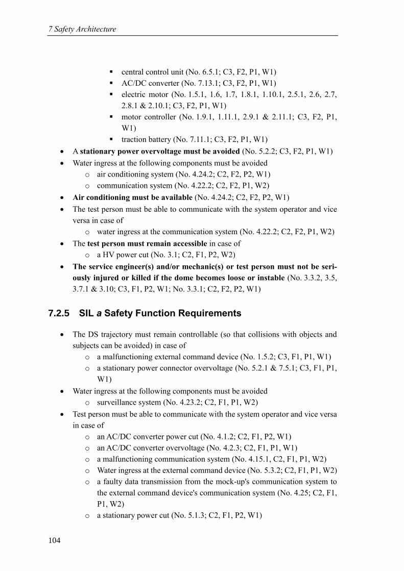
7 Safety Architecture
104
▪ central control unit (No. 6.5.1; C3, F2, P1, W1)
▪ AC/DC converter (No. 7.13.1; C3, F2, P1, W1)
▪ electric motor (No. 1.5.1, 1.6, 1.7, 1.8.1, 1.10.1, 2.5.1, 2.6, 2.7,
2.8.1 & 2.10.1; C3, F2, P1, W1)
▪ motor controller (No. 1.9.1, 1.11.1, 2.9.1 & 2.11.1; C3, F2, P1,
W1)
▪ traction battery (No. 7.11.1; C3, F2, P1, W1)
• A stationary power overvoltage must be avoided (No. 5.2.2; C3, F2, P1, W1)
• Water ingress at the following components must be avoided
o air conditioning system (No. 4.24.2; C2, F2, P2, W1)
o communication system (No. 4.22.2; C2, F2, P1, W2)
• Air conditioning must be available (No. 4.24.2; C2, F2, P2, W1)
• The test person must be able to communicate with the system operator and vice
versa in case of
o water ingress at the communication system (No. 4.22.2; C2, F2, P1, W2)
• The test person must remain accessible in case of
o a HV power cut (No. 3.1; C2, F1, P2, W2)
• The service engineer(s) and/or mechanic(s) or test person must not be seri-
ously injured or killed if the dome becomes loose or instable (No. 3.3.2, 3.5,
3.7.1 & 3.10; C3, F1, P2, W1; No. 3.3.1; C2, F2, P2, W1)
7.2.5 SIL a Safety Function Requirements
• The DS trajectory must remain controllable (so that collisions with objects and
subjects can be avoided) in case of
o a malfunctioning external command device (No. 1.5.2; C3, F1, P1, W1)
o a stationary power connector overvoltage (No. 5.2.1 & 7.5.1; C3, F1, P1,
W1)
• Water ingress at the following components must be avoided
o surveillance system (No. 4.23.2; C2, F1, P1, W2)
• Test person must be able to communicate with the system operator and vice versa
in case of
o an AC/DC converter power cut (No. 4.1.2; C2, F1, P2, W1)
o an AC/DC converter overvoltage (No. 4.2.3; C2, F1, P1, W1)
o a malfunctioning communication system (No. 4.15.1, C2, F1, P1, W2)
o Water ingress at the external command device (No. 5.3.2; C2, F1, P1, W2)
o a faulty data transmission from the mock-up's communication system to
the external command device's communication system (No. 4.25; C2, F1,
P1, W2)
o a stationary power cut (No. 5.1.3; C2, F1, P2, W1)
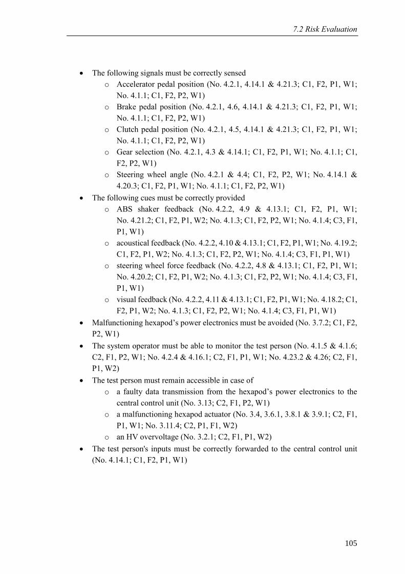
7.2 Risk Evaluation
105
• The following signals must be correctly sensed
o Accelerator pedal position (No. 4.2.1, 4.14.1 & 4.21.3; C1, F2, P1, W1;
No. 4.1.1; C1, F2, P2, W1)
o Brake pedal position (No. 4.2.1, 4.6, 4.14.1 & 4.21.3; C1, F2, P1, W1;
No. 4.1.1; C1, F2, P2, W1)
o Clutch pedal position (No. 4.2.1, 4.5, 4.14.1 & 4.21.3; C1, F2, P1, W1;
No. 4.1.1; C1, F2, P2, W1)
o Gear selection (No. 4.2.1, 4.3 & 4.14.1; C1, F2, P1, W1; No. 4.1.1; C1,
F2, P2, W1)
o Steering wheel angle (No. 4.2.1 & 4.4; C1, F2, P2, W1; No. 4.14.1 &
4.20.3; C1, F2, P1, W1; No. 4.1.1; C1, F2, P2, W1)
• The following cues must be correctly provided
o ABS shaker feedback (No. 4.2.2, 4.9 & 4.13.1; C1, F2, P1, W1;
No. 4.21.2; C1, F2, P1, W2; No. 4.1.3; C1, F2, P2, W1; No. 4.1.4; C3, F1,
P1, W1)
o acoustical feedback (No. 4.2.2, 4.10 & 4.13.1; C1, F2, P1, W1; No. 4.19.2;
C1, F2, P1, W2; No. 4.1.3; C1, F2, P2, W1; No. 4.1.4; C3, F1, P1, W1)
o steering wheel force feedback (No. 4.2.2, 4.8 & 4.13.1; C1, F2, P1, W1;
No. 4.20.2; C1, F2, P1, W2; No. 4.1.3; C1, F2, P2, W1; No. 4.1.4; C3, F1,
P1, W1)
o visual feedback (No. 4.2.2, 4.11 & 4.13.1; C1, F2, P1, W1; No. 4.18.2; C1,
F2, P1, W2; No. 4.1.3; C1, F2, P2, W1; No. 4.1.4; C3, F1, P1, W1)
• Malfunctioning hexapod’s power electronics must be avoided (No. 3.7.2; C1, F2,
P2, W1)
• The system operator must be able to monitor the test person (No. 4.1.5 & 4.1.6;
C2, F1, P2, W1; No. 4.2.4 & 4.16.1; C2, F1, P1, W1; No. 4.23.2 & 4.26; C2, F1,
P1, W2)
• The test person must remain accessible in case of
o a faulty data transmission from the hexapod’s power electronics to the
central control unit (No. 3.13; C2, F1, P2, W1)
o a malfunctioning hexapod actuator (No. 3.4, 3.6.1, 3.8.1 & 3.9.1; C2, F1,
P1, W1; No. 3.11.4; C2, P1, F1, W2)
o an HV overvoltage (No. 3.2.1; C2, F1, P1, W2)
• The test person's inputs must be correctly forwarded to the central control unit
(No. 4.14.1; C1, F2, P1, W1)
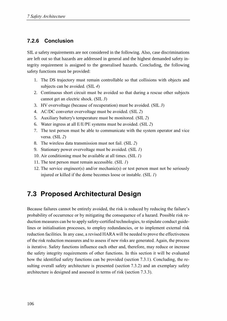
7 Safety Architecture
106
7.2.6 Conclusion
SIL a safety requirements are not considered in the following. Also, case discriminations
are left out so that hazards are addressed in general and the highest demanded safety in-
tegrity requirement is assigned to the generalised hazards. Concluding, the following
safety functions must be provided:
1. The DS trajectory must remain controllable so that collisions with objects and
subjects can be avoided. (SIL 4)
2. Continuous short circuit must be avoided so that during a rescue other subjects
cannot get an electric shock. (SIL 3)
3. HV overvoltage (because of recuperation) must be avoided. (SIL 3)
4. AC/DC converter overvoltage must be avoided. (SIL 2)
5. Auxiliary battery's temperature must be monitored. (SIL 2)
6. Water ingress at all E/E/PE systems must be avoided. (SIL 2)
7. The test person must be able to communicate with the system operator and vice
versa. (SIL 2)
8. The wireless data transmission must not fail. (SIL 2)
9. Stationary power overvoltage must be avoided. (SIL 1)
10. Air conditioning must be available at all times. (SIL 1)
11. The test person must remain accessible. (SIL 1)
12. The service engineer(s) and/or mechanic(s) or test person must not be seriously
injured or killed if the dome becomes loose or instable. (SIL 1)
7.3 Proposed Architectural Design
Because failures cannot be entirely avoided, the risk is reduced by reducing the failure’s
probability of occurrence or by mitigating the consequence of a hazard. Possible risk re-
duction measures can be to apply safety-certified technologies, to stipulate conduct guide-
lines or initialisation processes, to employ redundancies, or to implement external risk
reduction facilities. In any case, a revised HARA will be needed to prove the effectiveness
of the risk reduction measures and to assess if new risks are generated. Again, the process
is iterative. Safety functions influence each other and, therefore, may reduce or increase
the safety integrity requirements of other functions. In this section it will be evaluated
how the identified safety functions can be provided (section 7.3.1). Concluding, the re-
sulting overall safety architecture is presented (section 7.3.2) and an exemplary safety
architecture is designed and assessed in terms of risk (section 7.3.3).
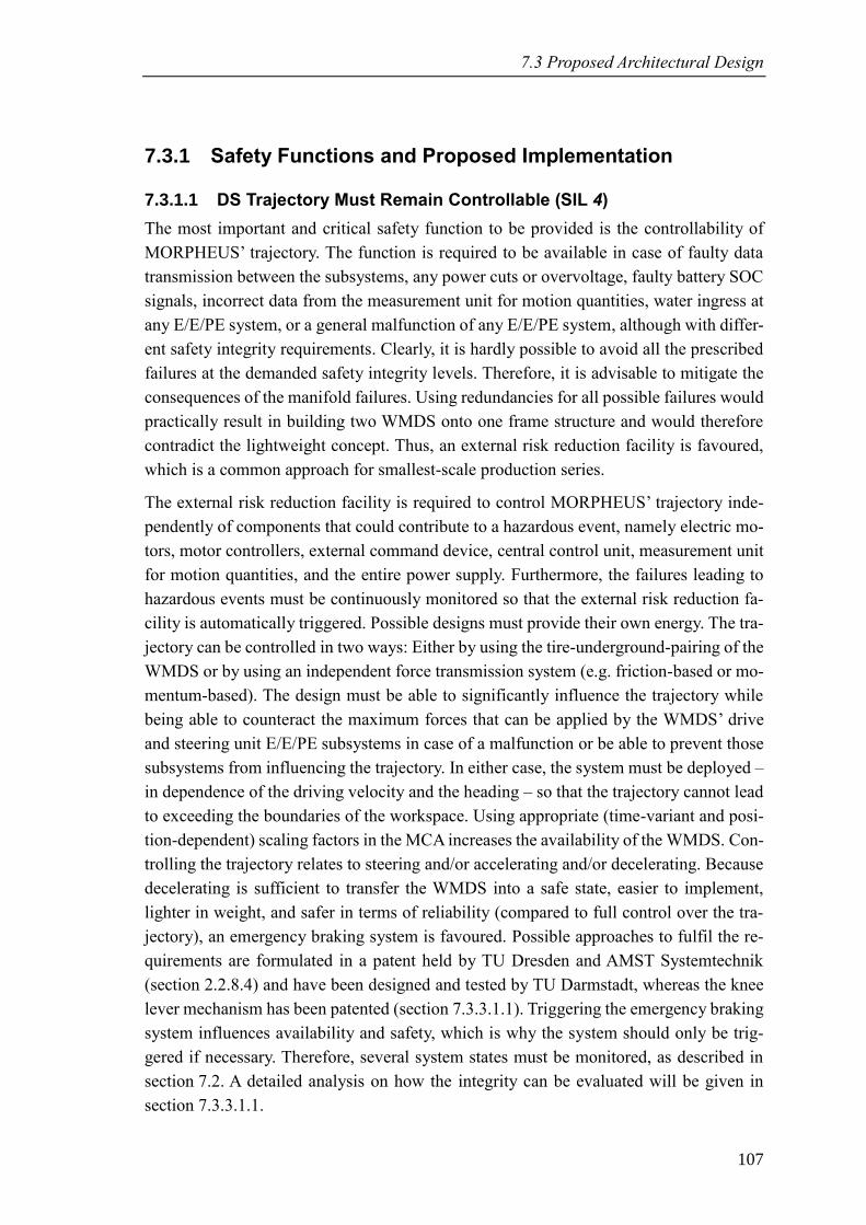
7.3 Proposed Architectural Design
107
7.3.1 Safety Functions and Proposed Implementation
7.3.1.1 DS Trajectory Must Remain Controllable (SIL 4)
The most important and critical safety function to be provided is the controllability of
MORPHEUS’ trajectory. The function is required to be available in case of faulty data
transmission between the subsystems, any power cuts or overvoltage, faulty battery SOC
signals, incorrect data from the measurement unit for motion quantities, water ingress at
any E/E/PE system, or a general malfunction of any E/E/PE system, although with differ-
ent safety integrity requirements. Clearly, it is hardly possible to avoid all the prescribed
failures at the demanded safety integrity levels. Therefore, it is advisable to mitigate the
consequences of the manifold failures. Using redundancies for all possible failures would
practically result in building two WMDS onto one frame structure and would therefore
contradict the lightweight concept. Thus, an external risk reduction facility is favoured,
which is a common approach for smallest-scale production series.
The external risk reduction facility is required to control MORPHEUS’ trajectory inde-
pendently of components that could contribute to a hazardous event, namely electric mo-
tors, motor controllers, external command device, central control unit, measurement unit
for motion quantities, and the entire power supply. Furthermore, the failures leading to
hazardous events must be continuously monitored so that the external risk reduction fa-
cility is automatically triggered. Possible designs must provide their own energy. The tra-
jectory can be controlled in two ways: Either by using the tire-underground-pairing of the
WMDS or by using an independent force transmission system (e.g. friction-based or mo-
mentum-based). The design must be able to significantly influence the trajectory while
being able to counteract the maximum forces that can be applied by the WMDS’ drive
and steering unit E/E/PE subsystems in case of a malfunction or be able to prevent those
subsystems from influencing the trajectory. In either case, the system must be deployed –
in dependence of the driving velocity and the heading – so that the trajectory cannot lead
to exceeding the boundaries of the workspace. Using appropriate (time-variant and posi-
tion-dependent) scaling factors in the MCA increases the availability of the WMDS. Con-
trolling the trajectory relates to steering and/or accelerating and/or decelerating. Because
decelerating is sufficient to transfer the WMDS into a safe state, easier to implement,
lighter in weight, and safer in terms of reliability (compared to full control over the tra-
jectory), an emergency braking system is favoured. Possible approaches to fulfil the re-
quirements are formulated in a patent held by TU Dresden and AMST Systemtechnik
(section 2.2.8.4) and have been designed and tested by TU Darmstadt, whereas the knee
lever mechanism has been patented (section 7.3.3.1.1). Triggering the emergency braking
system influences availability and safety, which is why the system should only be trig-
gered if necessary. Therefore, several system states must be monitored, as described in
section 7.2. A detailed analysis on how the integrity can be evaluated will be given in
section 7.3.3.1.1.
7 Safety Architecture
108
7.3.1.2 Continuous Short Circuit Must be Avoided (SIL 3)
A continuous short circuit can only arise from the power supply E/E/PE subsystem itself
because only here energy is stored. Although energy can be generated by the electric mo-
tors during recuperation, this process is not continuous (limited kinetic energy is con-
verted to electric energy and a rescue will only be initiated when MORPHEUS is in stand-
still) and is separately dealt with in section 7.3.1.3.
The safety function must monitor if there is a short circuit. This can be done by an Insu-
lation Monitoring Device (IMD), e.g. the patented A-Isometer of the company Bender
that measures the current between the reference ground and the insulated as well as active
conductor. If the insulation resistance is below a predefined threshold, a short circuit is
probable, and the power supply must be cut. For cutting the power supply, power contac-
tors are needed.
7.3.1.3 HV Overvoltage Must be Avoided (SIL 3)
HV overvoltage can arise from a malfunction in the power supply E/E/PE subsystem or
from recuperation with the electric motors. Here, the safety function for the latter case is
addressed because the power supply is monitored by its own safety certified BMS. Recu-
peration can be problematic because some types of accumulators can only absorb a frac-
tion of the power that can be drawn from it.
The safety function must continuously monitor the current drawn from the electric motors
during recuperation and limit this current to a value that is absorbable for the accumulator
(20 A (DC) in MORPHEUS’ setup). The safety function can easily be implemented in the
motor controllers since the current to and from the electric motors is continuously meas-
ured and the controllers provide a function to limit the recuperation current164. If this risk
reduction measure does not fulfil the safety integrity requirement sufficiently, a diode
(e.g. surge protector) connected between the motor controllers and the traction battery
can limit the power that must be absorbed by the accumulator.
7.3.1.4 AC/DC Converter Overvoltage Must be Avoided (SIL 2)
In case of a malfunctioning AC/DC converter, an overvoltage at the mock-up E/E/PE
subsystem might endanger the test person’s health and that of subjects trying to rescue
the test person as well if the overvoltage is continuous.
The continuous overvoltage safety function has already been addressed (section 7.3.1.2),
thus, only very short overvoltage is possible until the IMD operates the power contactors.
Then, the test person can be rescued without putting the rescue personnel at unreasonable
164 E.g. UNITEK Industrie Elektronik GmbH: Manual Bamocar-D3 (2017).
7.3 Proposed Architectural Design
109
risk. If this risk reduction measure does not fulfil the safety integrity requirement suffi-
ciently, a fuse may limit the output power of the AC/DC converter to a safe value. Fur-
thermore, a safety-certified AC/DC converter may be used.
7.3.1.5 Auxiliary Battery's Temperature Must be Monitored (SIL 2)
If the temperature of the auxiliary battery is not monitored, overheating may not be de-
tected, leading to short circuit and/or fire hazard.
(Continuous) short circuit has already been addressed (section 7.3.1.2). Auxiliary batter-
ies with integrated temperature sensors are available on the market and must be intro-
duced to the system. Thus, the safety function can be provided either by an automatic
shutdown of the auxiliary battery in case of overheating (in this case power contactors
must be integrated that can be operated by the auxiliary BMS) or manually by the system
operator who would be obliged to monitor the auxiliary battery’s temperature.
7.3.1.6 Water Ingress Must be Avoided (SIL 2)
Water ingress is a safety issue for all components except for the surveillance system (co-
incidence of water ingress at surveillance system and a health issue of test person is very
unlikely).
Instead of using waterproof components, which would contradict the lightweight concept,
the occurrence of water should be avoided. On the one hand, the skilled operator can
monitor the weather (when using MORPHEUS outdoors) and take precautionary coun-
termeasures (e.g. driving MORPHEUS back into its hall). If the countermeasures have
been taken too late, a sufficiently large, waterproof cover must be provided that can with-
stand the allowed wind speeds and can be appropriately secured so that MORPHEUS can
endure wet weather. On the other hand, all subjects interacting with MORPHEUS must
be instructed not to bring any liquids to the system (e.g. for drinking). Condensation, e.g.
from the air conditioning, must be collected.
7.3.1.7 The Test Person Must be Able to Communicate with the System
Operator and Vice Versa (SIL 2)
The bidirectional communication between the test person and the system operator is im-
portant in case of health issues of the test person or if the situation is unclear to the test
person. In the latter case, the test person could unbuckle and move within the dome while
driving simulation is in progress.
The use of a safety-certified communication system could increase the availability. If the
test person has a health issue, the system operator can still monitor the test person through
the surveillance system. The test person must be instructed not to unbuckle under any
circumstances until he or she is told to do so by the system operator. If these safety func-
tions do not fulfil the safety integrity requirement sufficiently, the buckles could be re-
mote controlled by the system operator so that the test person is not able to unbuckle him-
7 Safety Architecture
110
or herself. Of course, in case of a power cut, these automatic buckles would need a me-
chanical emergency release or be directly unlocked.
7.3.1.8 The Wireless Data Transmission Must Not Fail (SIL 2)
Wireless data is transmitted between the external command device E/E/PE subsystem and
the IPG Roadbox as well as the mock-up E/E/PE subsystem’s communication and sur-
veillance system.
If the emergency braking safety function (section 7.3.1.1) is implemented, the safety func-
tion can be reduced to “a wireless data dropout must be diagnosed”. The diagnosis can be
done by using more than one transmission channel and comparing the signals. If the num-
ber of transmission channels is sufficiently large, it is even possible to use the signals, if
one channel fails.
7.3.1.9 Stationary Power Overvoltage Must be Avoided (SIL 1)
In case of a stationary power overvoltage, the health of the system operator(s) might be
endangered as well as that of subjects trying to rescue the system operator(s) if the over-
voltage is continuous.
The continuous overvoltage safety function has already been addressed (section 7.3.1.2),
thus only very short overvoltage is possible until the IMD operates the power contactors.
Then, the system operator can be rescued without putting the rescue personnel at unrea-
sonable risk. If this risk reduction measure does not fulfil the safety integrity requirement
sufficiently, a fuse may limit the output power of the stationary power connector to a safe
value.
7.3.1.10 Air Conditioning Must be Available (SIL 1)
This safety function requirement was formulated in combination with water ingress at the
air conditioning. If water ingress can be avoided, the safety integrity requirement drops
to level a and, therefore, must not be accounted for.
7.3.1.11 The Test Person Must Remain Accessible (SIL 1)
In case the hexapod cannot be operated (e.g. HV power cut, malfunctioning hexapod,
etc.), the test person must remain accessible for rescue in any position of the hexapod.
This safety function can be fulfilled by providing a ladder or some other kind of mobile
entry aid. In MORPHEUS’ current setup, the height of the entrance to the dome is about
1 m above floor level. Even if the dome is fully tilted (18°) and at maximum heave
(75 mm), this would result in an entrance level of about 1.5 m.
7.3.1.12 Nobody Must be Injured or Killed if the Dome Becomes Loose or
Instable (SIL 1)
In case of a malfunction within the hexapod E/E/PE subsystem, it might happen that –
due to mechanical stress because of a violation of the inverse kinematics model’s integrity
7.3 Proposed Architectural Design
111
– one or more actuators fail, and the dome becomes instable so that the position and mo-
tion cannot be controlled. In a worst-case scenario, the remaining actuators cannot bear
the static and dynamic load of the dome so that the dome becomes entirely loose and
might fall off the self-driving platform. These hazards can endanger system engineer(s)
and/or mechanic(s) during maintenance or test drives as well as the test person during
regular driving simulation.
The safety function must be able to prevent the dome from falling off the self-driving
platform in any case. Strengthened actuators and actuator mounts could achieve this. An-
other option is to utilise restraining straps that only come into effect if the maximum
stroke of the actuators is exceeded. Thus, the position can be controlled to some extent
but high accelerations and the risk of crushing (a) system engineer(s) and/or mechanic(s)
are still present. Using actuators with a self-locking effect cannot prevent unwanted mo-
tion because already one malfunctioning actuator makes one DOF uncontrollable. In any
case, the system engineer(s) and mechanic(s) must be instructed to stand back of the hex-
apod and self-driving platform as soon as power is supplied to the hexapod, steering unit,
or drive unit E/E/PE subsystem. In addition, putting a bellows over the hexapod reduces
the risk of being crushed significantly.
7.3.2 Overall Safety Architecture
An external emergency braking system is employed that disconnects the tires from the
underground, supplies its own energy, and is triggered either by a safety logic or manually
by the system operator. The safety logic itself must be programmed in a fail-safe manner,
e.g. in a programmable logic controller, and in such a way that emergency braking is
triggered as soon as the programmable logic controller does not send an “OK”-signal.
Analysing the revised HARA, with all safety functions implemented except the external
emergency braking system, revealed that the following states must be monitored with the
outlined safety integrity requirements:
• Malfunctioning of (SIL 1)
o AC/DC converter
o measurement unit for motion quantities
o auxiliary battery
o electric motor
o external command device
o central control unit
o motor controller
o traction battery
o stationary power connector
7 Safety Architecture
112
• HV overvoltage from the traction battery to steering and/or drive unit E/E/PE sub-
systems’ motor controllers (SIL 2)
• HV overvoltage from the steering or drive unit E/E/PE subsystems’ motor con-
trollers to the traction battery (recuperation) (SIL 1)
• HV power cut between the traction battery and the steering and (SIL 2)/or (SIL 1)
drive unit E/E/PE subsystems’ motor controllers
• LV overvoltage from the auxiliary battery to steering and/or drive unit E/E/PE
subsystems’ motor controllers and/or WMDS dynamics control E/E/PE subsystem
(SIL 1)
• LV power cut between the auxiliary battery and the steering and (SIL 2)/or (SIL 1)
drive unit E/E/PE subsystems’ motor controllers
• LV power cut between the auxiliary battery and the WMDS dynamics control
E/E/PE subsystem (SIL 2)
• AC/DC converter overvoltage (SIL 2)
• Stationary power connector overvoltage (SIL 1)
• Stationary power connector power cut (SIL 2)
• Faulty data transmission between the central control unit and the
o Auxiliary battery (SOC) (SIL 2)
o Traction battery (SOC) (SIL 2)
o External command device (SIL 2)
o Drive unit’s motor controllers (SIL 2)
o Steering unit’s motor controllers (SIL 1)
o measurement unit for motion quantities (SIL 1)
• Incorrect data from the measurement unit for motion quantities (SIL 2)
Especially for wireless data transmission, at least two channels must be employed, mak-
ing a diagnosis possible. The MCA must be adapted so that the driving velocity is suffi-
ciently low that emergency braking is always possible without leaving the workspace.
An IMD monitors the insulation integrity and operates power contactors in the power
supply E/E/PE subsystem if a short circuit is detected. An additional power contactor is
integrated into the auxiliary battery and can be operated by the auxiliary battery’s BMS.
The auxiliary battery itself is replaced by a version with integrated temperature sensors.
Fuses between motor controllers and traction battery, between the AC/DC converter and
the mock-up E/E/PE subsystem, and between the stationary power connector and the ex-
ternal command device prevent overloads. The recuperation current from the electric
motors is limited within the motor controllers to a value that is absorbable for the accu-
mulator.
A sufficiently large, waterproof cover must be provided to the system operator(s) to avoid
water ingress in case of sudden weather changes. In addition, a sufficiently large ladder
7.3 Proposed Architectural Design
113
or other kind of entry aid must be provided to be able to rescue the test person from the
dome if the hexapod is not operable.
The hexapod is put into a bellows to prevent anybody from being crushed. Restraining
straps prevent the dome from falling off the self-driving platform if more than one actu-
ator breaks.
The conduct guidelines prohibit all subjects interacting with MORPHEUS from bringing
liquids into the system. Furthermore, the test person must be instructed not to unbuckle
under any circumstances unless he or she is told to do so by the system operator. System
engineers and mechanics must be instructed to stand back of the system when HV is
switched on unless direct contact with the system is absolutely essential. The system op-
erator(s) is/are required to monitor the weather if MORPHEUS is used outdoors so that
countermeasures can be taken at an early stage if wet weather occurs and to monitor
MORPHEUS’ workspace for unauthorised subjects. He or she is also instructed to drive
with low velocity in manual mode when MORPHEUS is close to its workspace bounda-
ries and to thoroughly check MORPHEUS’ workspace for obstacles prior to the initiali-
sation of a driving simulation.
Revising the HARA revealed that the following safety functions must be implemented,
too, for reducing all hazards to a SIL of a: Self-programmed software, especially for the
MCA and MC, must be externally reviewed and thoroughly tested before putting into
operation. If this measure will not fulfil the safety integrity requirement, an outer software
layer could be implemented that monitors only the very safety-relevant information (e.g.
absolute position in workspace and target vs. actual motion) and can directly activate the
external emergency braking system. The HV accumulator and its BMS – although
safety-oriented – must provide a high availability so that a shutdown of the HV power
supply is unlikely.
The full list of revised hazards can be found in annexe C.3, where all hazardous events
have been evaluated with a SIL of a.
7.3.3 Exemplary Application of the Safety Architecture
In this section, a specific, exemplary application of the safety architecture will be evalu-
ated in regard of its functional safety. The application includes the safety functions exter-
nal emergency braking E/E/PE system and the IMD E/E/PE element.
7.3.3.1 Determination of the Limits of Machinery
The users, uses cases, and environment are identical with those of MORPHEUS (cf. sec-
tions 7.1.1.1, 7.1.1.2, and 7.1.1.4).
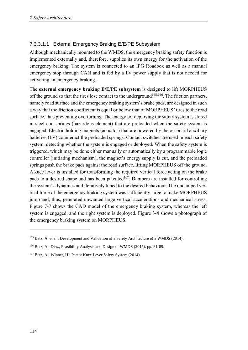
7 Safety Architecture
114
7.3.3.1.1 External Emergency Braking E/E/PE Subsystem
Although mechanically mounted to the WMDS, the emergency braking safety function is
implemented externally and, therefore, supplies its own energy for the activation of the
emergency braking. The system is connected to an IPG Roadbox as well as a manual
emergency stop through CAN and is fed by a LV power supply that is not needed for
activating an emergency braking.
The external emergency braking E/E/PE subsystem is designed to lift MORPHEUS
off the ground so that the tires lose contact to the underground165,166. The friction partners,
namely road surface and the emergency braking system’s brake pads, are designed in such
a way that the friction coefficient is equal or below that of MORPHEUS’ tires to the road
surface, thus preventing overturning. The energy for deploying the safety system is stored
in steel coil springs (hazardous element) that are preloaded when the safety system is
engaged. Electric holding magnets (actuator) that are powered by the on-board auxiliary
batteries (LV) counteract the preloaded springs. Contact switches are used in each safety
system, detecting whether the system is engaged or deployed. When the safety system is
triggered, which may be done either manually or automatically by a programmable logic
controller (initiating mechanism), the magnet’s energy supply is cut, and the preloaded
springs push the brake pads against the road surface, lifting MORPHEUS off the ground.
A knee lever is installed for transforming the required vertical force acting on the brake
pads to a desired shape and has been patented167. Dampers are installed for controlling
the system’s dynamics and iteratively tuned to the desired behaviour. The undamped ver-
tical force of the emergency braking system was sufficiently large to make MORPHEUS
jump and, thus, generated unwanted large vertical accelerations and mechanical stress.
Figure 7-7 shows the CAD model of the emergency braking system, whereas the left
system is engaged, and the right system is deployed. Figure 3-4 shows a photograph of
the emergency braking system on MORPHEUS.
165 Betz, A. et al.: Development and Validation of a Safety Architecture of a WMDS (2014).
166 Betz, A.: Diss., Feasibility Analysis and Design of WMDS (2015). pp. 81-89.
167 Betz, A.; Winner, H.: Patent Knee Lever Safety System (2014).
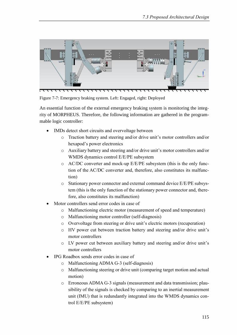
7.3 Proposed Architectural Design
115
Figure 7-7: Emergency braking system. Left: Engaged, right: Deployed
An essential function of the external emergency braking system is monitoring the integ-
rity of MORPHEUS. Therefore, the following information are gathered in the program-
mable logic controller:
• IMDs detect short circuits and overvoltage between
o Traction battery and steering and/or drive unit’s motor controllers and/or
hexapod’s power electronics
o Auxiliary battery and steering and/or drive unit’s motor controllers and/or
WMDS dynamics control E/E/PE subsystem
o AC/DC converter and mock-up E/E/PE subsystem (this is the only func-
tion of the AC/DC converter and, therefore, also constitutes its malfunc-
tion)
o Stationary power connector and external command device E/E/PE subsys-
tem (this is the only function of the stationary power connector and, there-
fore, also constitutes its malfunction)
• Motor controllers send error codes in case of
o Malfunctioning electric motor (measurement of speed and temperature)
o Malfunctioning motor controller (self-diagnosis)
o Overvoltage from steering or drive unit’s electric motors (recuperation)
o HV power cut between traction battery and steering and/or drive unit’s
motor controllers
o LV power cut between auxiliary battery and steering and/or drive unit’s
motor controllers
• IPG Roadbox sends error codes in case of
o Malfunctioning ADMA G-3 (self-diagnosis)
o Malfunctioning steering or drive unit (comparing target motion and actual
motion)
o Erroneous ADMA G-3 signals (measurement and data transmission; plau-
sibility of the signals is checked by comparing to an inertial measurement
unit (IMU) that is redundantly integrated into the WMDS dynamics con-
trol E/E/PE subsystem)
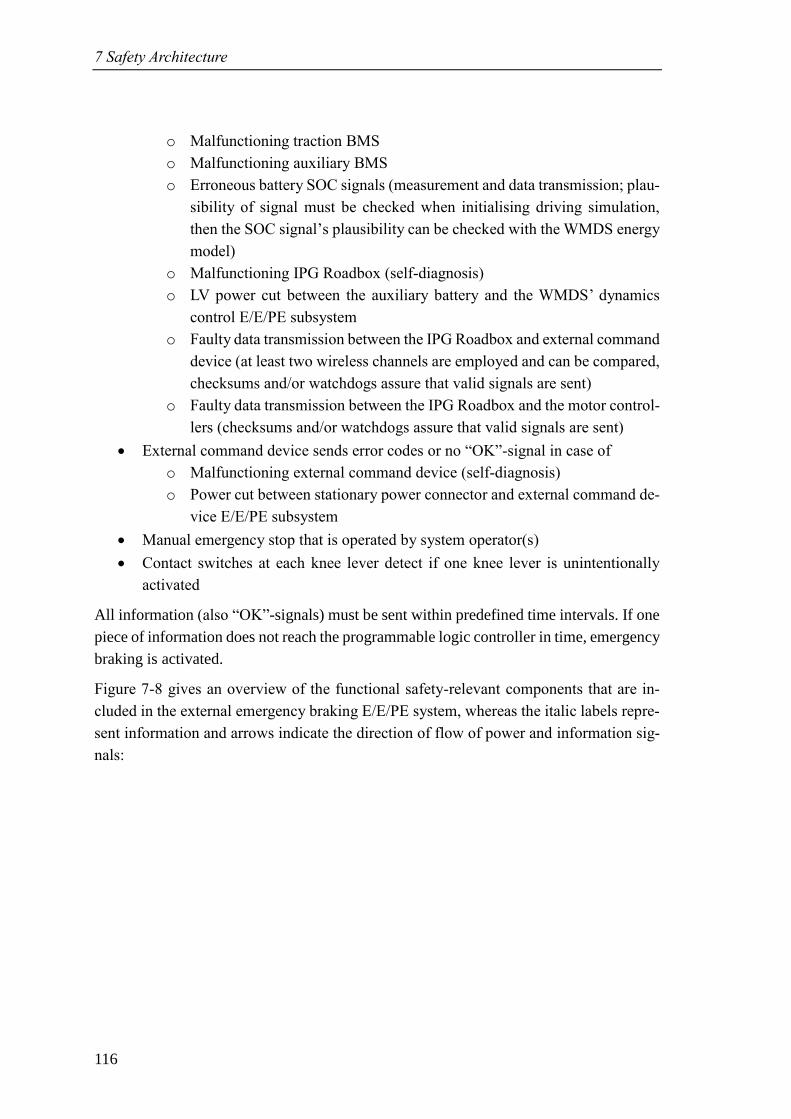
7 Safety Architecture
116
o Malfunctioning traction BMS
o Malfunctioning auxiliary BMS
o Erroneous battery SOC signals (measurement and data transmission; plau-
sibility of signal must be checked when initialising driving simulation,
then the SOC signal’s plausibility can be checked with the WMDS energy
model)
o Malfunctioning IPG Roadbox (self-diagnosis)
o LV power cut between the auxiliary battery and the WMDS’ dynamics
control E/E/PE subsystem
o Faulty data transmission between the IPG Roadbox and external command
device (at least two wireless channels are employed and can be compared,
checksums and/or watchdogs assure that valid signals are sent)
o Faulty data transmission between the IPG Roadbox and the motor control-
lers (checksums and/or watchdogs assure that valid signals are sent)
• External command device sends error codes or no “OK”-signal in case of
o Malfunctioning external command device (self-diagnosis)
o Power cut between stationary power connector and external command de-
vice E/E/PE subsystem
• Manual emergency stop that is operated by system operator(s)
• Contact switches at each knee lever detect if one knee lever is unintentionally
activated
All information (also “OK”-signals) must be sent within predefined time intervals. If one
piece of information does not reach the programmable logic controller in time, emergency
braking is activated.
Figure 7-8 gives an overview of the functional safety-relevant components that are in-
cluded in the external emergency braking E/E/PE system, whereas the italic labels repre-
sent information and arrows indicate the direction of flow of power and information sig-
nals:
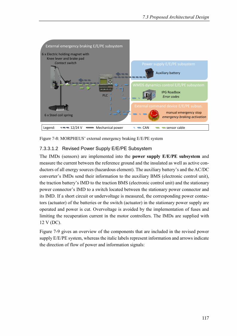
7.3 Proposed Architectural Design
117
Figure 7-8: MORPHEUS’ external emergency braking E/E/PE system
7.3.3.1.2 Revised Power Supply E/E/PE Subsystem
The IMDs (sensors) are implemented into the power supply E/E/PE subsystem and
measure the current between the reference ground and the insulated as well as active con-
ductors of all energy sources (hazardous element). The auxiliary battery’s and the AC/DC
converter’s IMDs send their information to the auxiliary BMS (electronic control unit),
the traction battery’s IMD to the traction BMS (electronic control unit) and the stationary
power connector’s IMD to a switch located between the stationary power connector and
its IMD. If a short circuit or undervoltage is measured, the corresponding power contac-
tors (actuator) of the batteries or the switch (actuator) in the stationary power supply are
operated and power is cut. Overvoltage is avoided by the implementation of fuses and
limiting the recuperation current in the motor controllers. The IMDs are supplied with
12 V (DC).
Figure 7-9 gives an overview of the components that are included in the revised power
supply E/E/PE system, whereas the italic labels represent information and arrows indicate
the direction of flow of power and information signals:
External emergency braking E/E/PE subsystem
WMDS dynamics control E/E/PE subsystem
Legend: 12/24 V Mechanical power CAN sensor cable
External command device E/E/PE subsys.
Power supply E/E/PE subsystem
6 x Steel coil spring
6 x Electric holding magnet withKnee lever and brake pad
Contact switch
PLCIPG RoadboxError codes
manual emergency stop emergency braking activation
Auxiliary battery
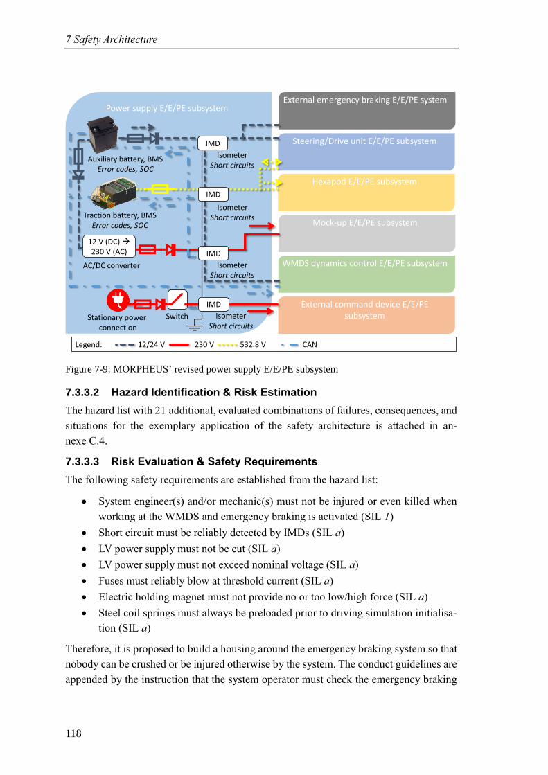
7 Safety Architecture
118
Figure 7-9: MORPHEUS’ revised power supply E/E/PE subsystem
7.3.3.2 Hazard Identification & Risk Estimation
The hazard list with 21 additional, evaluated combinations of failures, consequences, and
situations for the exemplary application of the safety architecture is attached in an-
nexe C.4.
7.3.3.3 Risk Evaluation & Safety Requirements
The following safety requirements are established from the hazard list:
• System engineer(s) and/or mechanic(s) must not be injured or even killed when
working at the WMDS and emergency braking is activated (SIL 1)
• Short circuit must be reliably detected by IMDs (SIL a)
• LV power supply must not be cut (SIL a)
• LV power supply must not exceed nominal voltage (SIL a)
• Fuses must reliably blow at threshold current (SIL a)
• Electric holding magnet must not provide no or too low/high force (SIL a)
• Steel coil springs must always be preloaded prior to driving simulation initialisa-
tion (SIL a)
Therefore, it is proposed to build a housing around the emergency braking system so that
nobody can be crushed or be injured otherwise by the system. The conduct guidelines are
appended by the instruction that the system operator must check the emergency braking
Power supply E/E/PE subsystem
IsometerShort circuits
Mock-up E/E/PE subsystem
WMDS dynamics control E/E/PE subsystem
Legend: 12/24 V 230 V 532.8 V CAN
Traction battery, BMSError codes, SOC
Auxiliary battery, BMSError codes, SOC
Steering/Drive unit E/E/PE subsystem
Hexapod E/E/PE subsystem
External command device E/E/PE subsystemStationary power
connection
AC/DC converter
External emergency braking E/E/PE system
IsometerShort circuits
IsometerShort circuits
12 V (DC) →230 V (AC)
IsometerShort circuits
IMD
IMD
IMD
Switch
IMD
7.4 Adaption to Full-Scale WMDS
119
system visually prior to initialising driving simulation. Especially checking if all steel coil
springs are preloaded is mandatory.
7.4 Adaption to Full-Scale WMDS
Besides the design changes in terms of size, weight, power, and energy supply, as de-
scribed in section 3.6, changes in the safety architecture are necessary as well when build-
ing a full-scale WMDS. The external emergency braking system can be kept, although
adapted in size and power to be able to handle the increased wheel load. The electric
architecture with IMDs and fuses can be kept, too. The increased size makes it difficult
to use a waterproof cover in case of sudden weather changes. Either the full-scale WMDS
is constructed in such a way that the system is at least safe in wet conditions when it is
shut down or some kind of aid must be provided to cover the WMDS in all possible
emergency states and under all environmental conditions. Because of the increased size
and the expectable stroke increase of the hexapod, it will become more difficult to rescue
the test person from the dome in case of emergency and power cut. Also, the WMDS’
workspace will probably increase, making it even more time consuming to reach the test
person on foot. A possible solution could be derived from passenger boarding stairs as
used in aviation (a.k.a. boarding ramps or stair car). This approach could also be used for
regular entrance to the dome, if mobile stairs is equipped with a top platform that is ad-
justable in height. A solution that is easier to implement are inflatable emergency slides
as also used in aviation that come into action in case of emergency. If the full-scale
WMDS is intended to be used with more than one test person simultaneously, a thorough
revision of the HARA must be conducted because many safety integrity requirements
resulted of the assumption that only one person can be injured or killed in the dome.
7.5 Discussion
A suitable safety architecture for WMDS in general has been found and theoretically
demonstrated to reduce risk to an acceptable level. It was surprising to find out that no
environment perception is required when subjects are restrained from entering the
WMDS’ driving area. Although the implementation of an external emergency braking
system comes to mind somewhat intuitively, this safety measure is demanded by a vast
number of safety requirements. Furthermore, the importance or the communication be-
tween test person and system operator could intuitively be underestimated.
Concluding, the hypothesis H1.2 cannot be falsified, considering the determined limits of
the WMDS, international functional safety standards, and state-of-the-art-technology.

121
8 Conclusion
The results presented within this thesis provide the next building block towards proving
general feasibility of WMDS. The falsification aspects power demand, energy demand,
and latency are practically researched in experiments and the falsification aspect safety
architecture in theory, trying to falsify the working hypotheses H1.1 and H1.2 (sec-
tions 1.2.3.1 and 1.2.3.2).
8.1 Wheeled Motion Base
H1.1: “The wheeled motion base of [FZD’s] WMDS [concept] with its dynamics lim-
ited by friction forces can simulate the horizontal dynamics of urban traffic for normal
driver behaviour considering common scaling factors” 168.
The falsification aspect power demand is researched with a verified power model. The
model is designed partially based on physical effects (power demand by mass moment of
inertia, self-alignment torque, and drill torque) and partially based on empirical findings
where the underlying physical effects were so complex that a detailed model would not
justify the effort required for modelling and parameterisation (driving resistance, steering
holding power, and electrical efficiency). The parameterisation is done with coasting ex-
periments (driving resistance model), steering holding torque experiments (steering hold-
ing power), and straight-line acceleration experiments (electrical efficiency). The param-
eterised model is then verified by conducting straight-line driving manoeuvres with
constant acceleration with MOPRHEUS while measuring the current and voltage at the
accumulator and comparing the experimental with the simulative results. The verified
model is then used to determine the power demand for different scaling factors.
MORPHEUS’ current setup can provide driving simulation up to scaling factors of 0.7.
For unscaled driving simulation, the electric motor power is sufficient, but the accumula-
tor’s power must be increased by the factor three. Thus, the aspect power demand is not
able to falsify hypothesis H1.1.
The falsification aspect energy demand is researched with a validated energy model that
is derived from the power model. The parameterised model is validated by driving a
90°-turn, a figure eight, and a scaled representative urban driving circuit with
168 Cf. Betz, A.: Diss., Feasibility Analysis and Design of WMDS (2015). p. 4.
8 Conclusion
122
MORPHEUS. The validated model is then used to simulate the energy demand in un-
scaled urban driving scenarios for the fully set-up MORPHEUS prototype. The highest
resulting average energy demand is extrapolated to the demanded 2 h experiment dura-
tion. Auxiliary energy consumers are measured and added to the energy demand by the
motion system. Although the accumulator used in MORPHEUS is not able to fulfil the
requirement, state-of-the-art accumulators are. Then, the accumulator’s energy must be
increased by the factor five, including the additional energy demand by the mass increase.
Thus, the aspect energy demand is not able to falsify hypothesis H1.1.
The falsification aspect latency is researched by imposing step inputs to MORPHEUS.
The experimental design is chosen so that the influence of the initial driving velocity, the
acceleration step input amplitude, and the type of control (acceleration and steering angle
step input) are considered. Whereas the acceleration step input amplitude showed no in-
fluence on latency if the indicator for latency is independent of the amplitude, the initial
driving velocity has a significant influence. Motion latency shows the highest value at
low driving velocities and asymptotically decreases at higher velocities. The steering an-
gle step input showed marginally higher latency than the acceleration step input. Consid-
ering inaccuracies in the measurement, this influence can be neglected. Concluding, the
highest ACL50 % was found at 7 m/s² acceleration step input amplitude and 0 driving ve-
locity with a value of 159 ms, which is above the requirement of 135 ms. The highest
ACLgain was found at 6 and 7 m/s² acceleration step input and 0 driving velocity with a
value of 104 ms, which is slightly above the requirement of 100 ms. Considering the con-
trol approach of keeping the WMDS in motion, the restrictive requirement for ACL50 %,
and the small deviation from the requirement, the aspect latency is not able to falsify
hypothesis H1.1.
8.2 Safety Architecture
H1.2: FZD’s WMDS concept does not bear an unacceptable risk to a human under any
environmental conditions and in any use case.
The falsification aspect of a safety architecture is investigated by conducting a HARA,
formulating safety requirements, and proposing a safety architecture design that fulfils
these requirements. The HARA yields 186 hazardous events that are addressed by
twelve main safety requirements, whereas the most important requirement is that the DS
trajectory must remain controllable so that collisions with objects and subjects can be
avoided with a SIL of 4. Five safety requirements address electrical safety (continuous
short circuit must be avoided (SIL 3), HV overvoltage because of recuperation must be
avoided (SIL 3), AC/DC converter overvoltage must be avoided (SIL 2), auxiliary bat-
tery's temperature must be monitored (SIL 2), and stationary power overvoltage must be
8.3 Outlook
123
avoided (SIL 1)). Furthermore, water ingress at all E/E/PE systems must be avoided
(SIL 2), the test person must be able to communicate with the system operator and vice
versa (SIL 2), the wireless data transmission must not fail (SIL 2), the test person must
remain accessible (SIL 1), and nobody must be seriously injured or killed if the dome
becomes loose or instable (SIL 1).
Being able to control the WMDS’ trajectory with the on-board power supply and actuators
under any given circumstances requires a tremendous effort in designing functions, signal
transmission, and software to fulfil the safety integrity requirement. Thus, the decision is
made for an external risk reduction facility, namely an emergency braking system, be-
cause this concept represents the easiest and thereby the safest way to control the trajec-
tory (in terms of reliability in comparison to a risk reduction facility intended to keep full
trajectory control over the WMDS). Monitoring all failures that require the emergency
braking system to be triggered is crucial. The electrical safety requirements are addressed
by implementing IMDs that control power contactors, limiting the recuperation current
in the motor controllers, implementing diodes and fuses, and by utilizing an auxiliary
battery with integrated temperature sensors. A multichannel wireless data transmission is
introduced. A weatherproof cover for the WMDS and a ladder for emergency evacuation
from the dome must be provided. The hexapod must be secured by restraining straps and
bellows must be installed. All other safety requirements can be addressed by conduct
guidelines.
The architecture is verified by re-assessing the hazardous events and by assessing the risk
for the newly introduced function and components. No hazardous events are identified
that require a risk reduction, thus, the architecture is able to fulfil the safety requirements
for a WMDS. Concluding, the falsification aspect of a safety architecture for WMDS is
not able to falsify hypothesis H1.2.
8.3 Outlook
Although hypothesis H1.1 and H1.2 were not falsified, it could not be ultimately proven
that they are practically valid. For hypothesis H1.1 this ultimate proof would imply in-
stalling sufficient accumulators for fulfilling the power and energy demand, increasing
the platform’s maximum velocity, and implementing the control approach of keeping the
WMDS in motion. For hypothesis H1.2 this ultimate proof would require implementing
the designed safety architecture into MORPHEUS. Although the emergency braking sys-
tem has already been installed on MORPHEUS and proven reliable, though sensitive, no
statistical evidence is provided. Not to mention the remaining safety functions.
8 Conclusion
124
Measurements revealed that due to vertical excitation from the uneven road surface and,
also, because of the lack of a suspension on MORPHEUS the wheel load fluctuation be-
comes so large at high velocities that the average friction coefficient is impaired. Besides
a solution by a very even pavement for operation, a vertical dynamics control of a WMDS,
as currently researched by Zöller169, is assumed to resolve this problem. Furthermore, the
signal quality in general would profit from reduced vertical excitation, as – most im-
portantly – would the immersion of the test person, too.
Of course, all falsification aspects have been researched with the scaled prototype
MORPHEUS. For the power and energy demand, no direct conclusions can be drawn for
the full-scale WMDS, because design changes would affect the validity of the power/en-
ergy model. Still, the found results increase the confidence in the feasibility of these as-
pects. Latency is not expected to change significantly, especially with the novel control
approach. Also, for a full-scale WMDS the HARA must be revised, and the safety archi-
tecture adapted to the updated safety requirements. Although specific for MORPHEUS,
the extensively conducted HARA provides a basis for assessing the risk of any WMDS.
Although these findings suggest that the falsification aspects will also not be able to fal-
sify the working hypotheses in a full-scale WMDS, the practical evidence is to be pro-
vided. Thus, designing and building a full-scale WMDS with a system to control the ver-
tical excitation induced by uneven driving surfaces and the updated safety architecture
applied to it is the next consequent step in FZD’s WMDS project. This full-scale WMDS
would be able to evaluate the immersion of the test person that can be accomplished with
the concept in comparison to state-of-the-art DS and, therewith, assumingly prove overall
practical feasibility and the claimed advantages of WMDS.
169 Zöller, C. et al.: Tires and Vertical Dynamics of WMDS (2017).
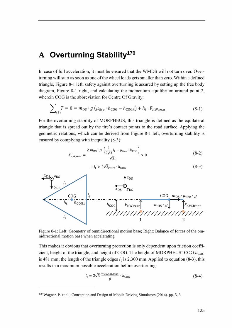
125
A Overturning Stability170
In case of full acceleration, it must be ensured that the WMDS will not turn over. Over-
turning will start as soon as one of the wheel loads gets smaller than zero. Within a defined
triangle, Figure 8-1 left, safety against overturning is assured by setting up the free body
diagram, Figure 8-1 right, and calculating the momentum equilibrium around point 2,
wherein COG is the abbreviation for Centre Of Gravity:
𝑇(2)
= 0 = 𝑚DS ∙ 𝑔 (𝜇tire ∙ ℎCOG − ℎCOG,t) + ℎt ∙ , ,rear (8-1)
For the overturning stability of MORPHEUS, this triangle is defined as the equilateral
triangle that is spread out by the tire’s contact points to the road surface. Applying the
geometric relations, which can be derived from Figure 8-1 left, overturning stability is
ensured by complying with inequality (8-3):
, ,rear =
2 𝑚DS ∙ 𝑔 (1
2√3𝑙t − 𝜇tire ∙ ℎCOG)
√3𝑙t> 0 (8-2)
𝑙t > 2√3𝜇tire ∙ ℎCOG (8-3)
Figure 8-1: Left: Geometry of omnidirectional motion base; Right: Balance of forces of the om-
nidirectional motion base when accelerating
This makes it obvious that overturning protection is only dependent upon friction coeffi-
cient, height of the triangle, and height of COG. The height of MORPHEUS‘ COG ℎCOG
is 481 mm; the length of the triangle edges 𝑙t is 2,300 mm. Applied to equation (8-3), this
results in a maximum possible acceleration before overturning:
𝑙t = 2√3 𝑎DS,hor,max
𝑔 ∙ ℎCOG (8-4)
170 Wagner, P. et al.: Conception and Design of Mobile Driving Simulators (2014). pp. 5, 8.
𝑙t
𝑙t
𝑙t
ℎCOG,tℎt
𝑥DS
𝑦DS
𝑧DS
, ,rear 𝑚DS 𝑔
𝑚DS 𝜇tire 𝑔
, , ront
1 2
ℎCOG
𝑥DS 𝑦DS
𝑧DS
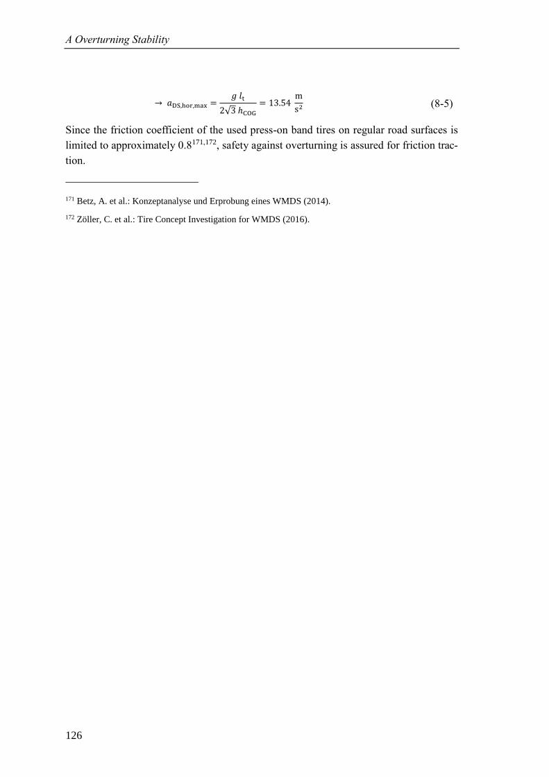
A Overturning Stability
126
𝑎DS,hor,max =𝑔 𝑙t
2√3 ℎCOG= 13.54
m
s2 (8-5)
Since the friction coefficient of the used press-on band tires on regular road surfaces is
limited to approximately 0.8171,172, safety against overturning is assured for friction trac-
tion.
171 Betz, A. et al.: Konzeptanalyse und Erprobung eines WMDS (2014).
172 Zöller, C. et al.: Tire Concept Investigation for WMDS (2016).
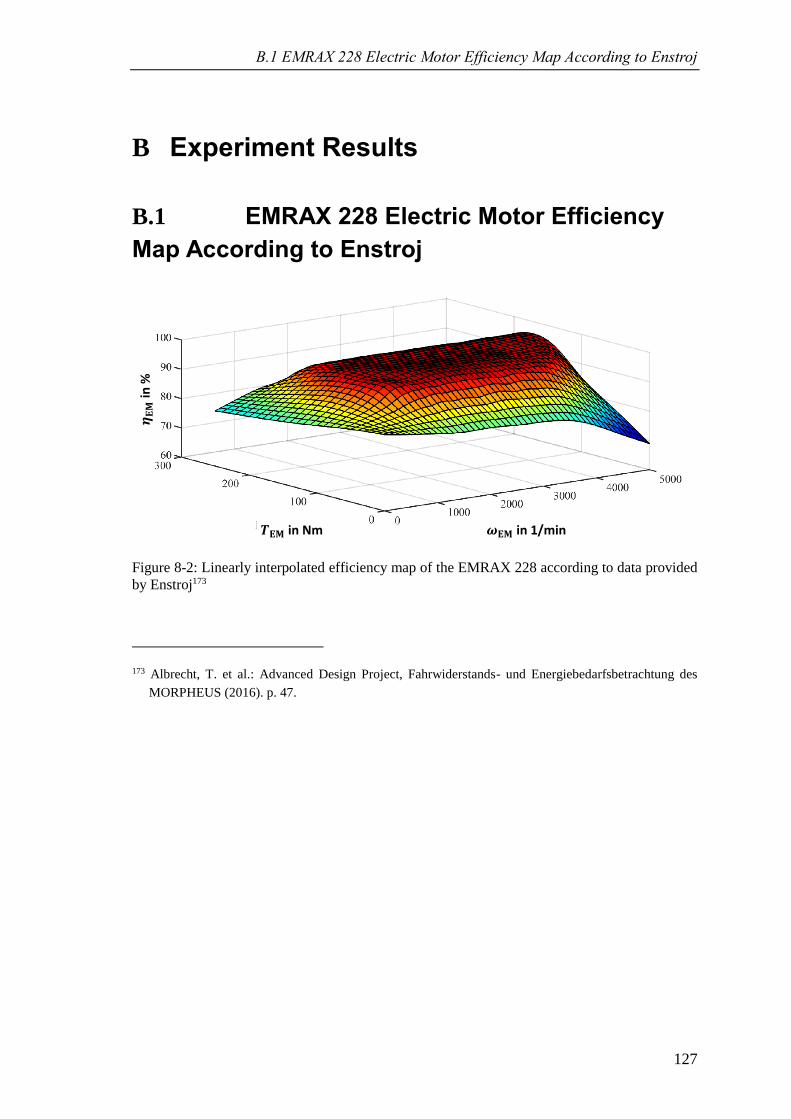
B.1 EMRAX 228 Electric Motor Efficiency Map According to Enstroj
127
B Experiment Results
B.1 EMRAX 228 Electric Motor Efficiency
Map According to Enstroj
Figure 8-2: Linearly interpolated efficiency map of the EMRAX 228 according to data provided
by Enstroj173
173 Albrecht, T. et al.: Advanced Design Project, Fahrwiderstands- und Energiebedarfsbetrachtung des
MORPHEUS (2016). p. 47.
𝐄𝐌 in Nm 𝐄𝐌 in 1/min
𝐄𝐌
in %
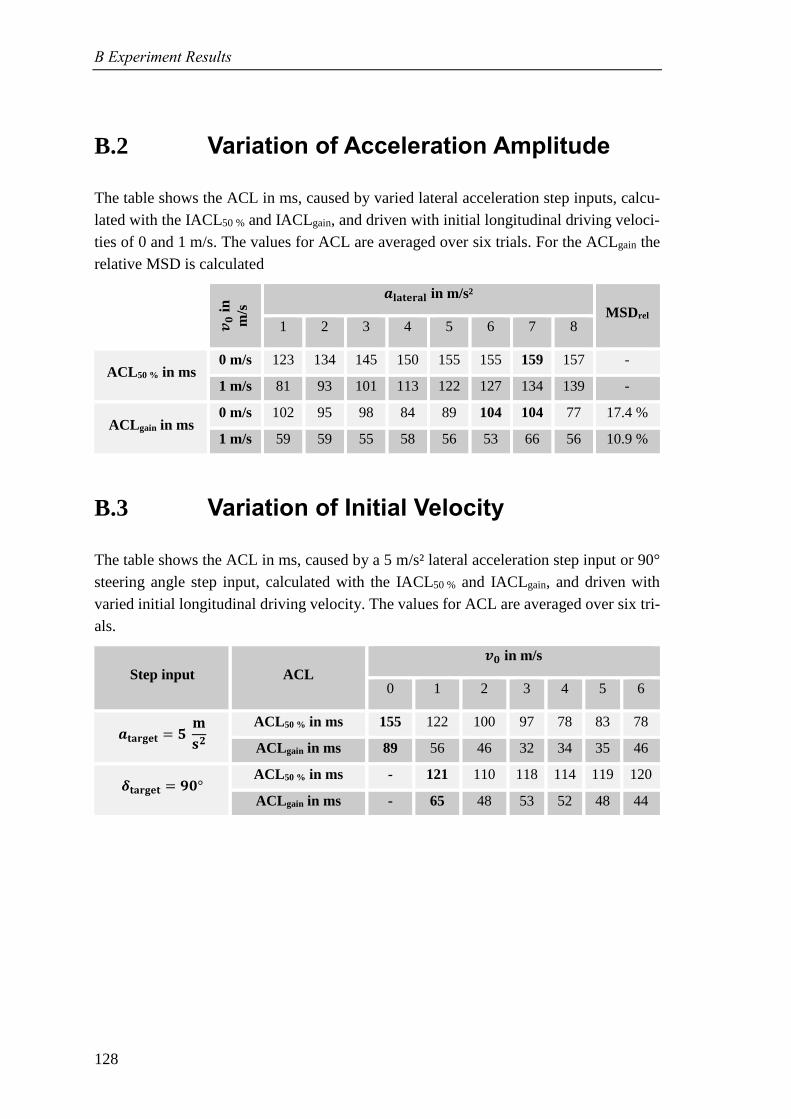
B Experiment Results
128
B.2 Variation of Acceleration Amplitude
The table shows the ACL in ms, caused by varied lateral acceleration step inputs, calcu-
lated with the IACL50 % and IACLgain, and driven with initial longitudinal driving veloci-
ties of 0 and 1 m/s. The values for ACL are averaged over six trials. For the ACLgain the
relative MSD is calculated
𝒗𝟎 i
n
m/s
𝒂𝐥𝐚𝐭𝐞𝐫𝐚𝐥 in m/s²
MSDrel 1 2 3 4 5 6 7 8
ACL50 % in ms 0 m/s 123 134 145 150 155 155 159 157 -
1 m/s 81 93 101 113 122 127 134 139 -
ACLgain in ms 0 m/s 102 95 98 84 89 104 104 77 17.4 %
1 m/s 59 59 55 58 56 53 66 56 10.9 %
B.3 Variation of Initial Velocity
The table shows the ACL in ms, caused by a 5 m/s² lateral acceleration step input or 90°
steering angle step input, calculated with the IACL50 % and IACLgain, and driven with
varied initial longitudinal driving velocity. The values for ACL are averaged over six tri-
als.
Step input ACL
𝒗𝟎 in m/s
0 1 2 3 4 5 6
𝒂𝐭𝐚𝐫𝐠𝐞𝐭 = 𝟓 𝐦
𝐬𝟐
ACL50 % in ms 155 122 100 97 78 83 78
ACLgain in ms 89 56 46 32 34 35 46
𝜹𝐭𝐚𝐫𝐠𝐞𝐭 = 𝟗𝟎° ACL50 % in ms - 121 110 118 114 119 120
ACLgain in ms - 65 48 53 52 48 44
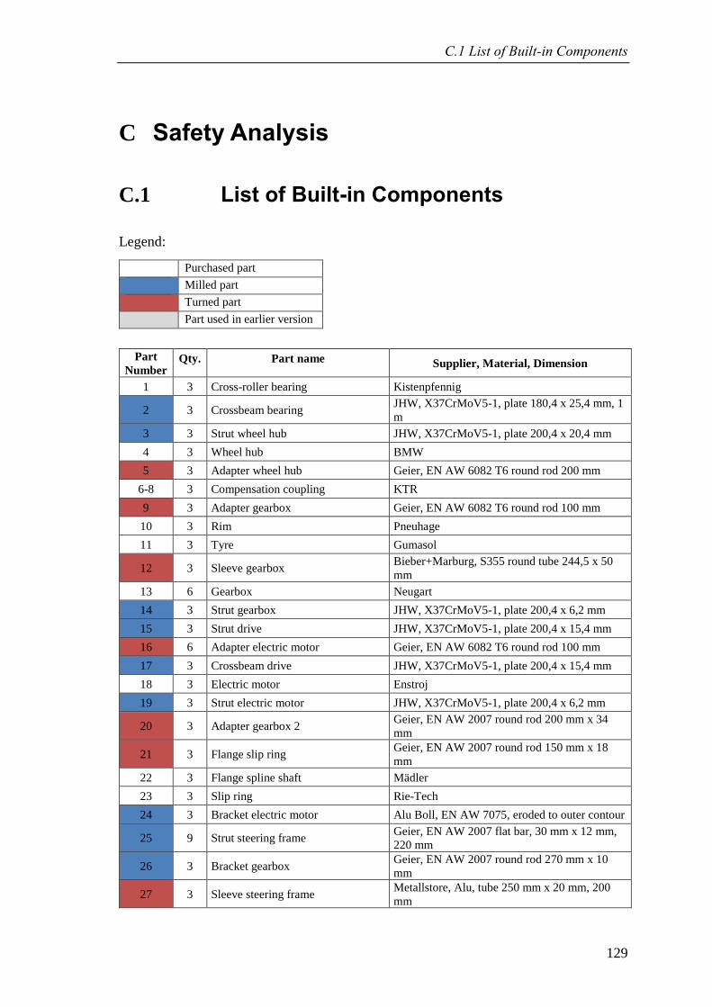
C.1 List of Built-in Components
129
C Safety Analysis
C.1 List of Built-in Components
Legend:
Purchased part
Milled part
Turned part
Part used in earlier version
Part
Number Qty. Part name Supplier, Material, Dimension
1 3 Cross-roller bearing Kistenpfennig
2 3 Crossbeam bearing JHW, X37CrMoV5-1, plate 180,4 x 25,4 mm, 1
m
3 3 Strut wheel hub JHW, X37CrMoV5-1, plate 200,4 x 20,4 mm
4 3 Wheel hub BMW
5 3 Adapter wheel hub Geier, EN AW 6082 T6 round rod 200 mm
6-8 3 Compensation coupling KTR
9 3 Adapter gearbox Geier, EN AW 6082 T6 round rod 100 mm
10 3 Rim Pneuhage
11 3 Tyre Gumasol
12 3 Sleeve gearbox Bieber+Marburg, S355 round tube 244,5 x 50
mm
13 6 Gearbox Neugart
14 3 Strut gearbox JHW, X37CrMoV5-1, plate 200,4 x 6,2 mm
15 3 Strut drive JHW, X37CrMoV5-1, plate 200,4 x 15,4 mm
16 6 Adapter electric motor Geier, EN AW 6082 T6 round rod 100 mm
17 3 Crossbeam drive JHW, X37CrMoV5-1, plate 200,4 x 15,4 mm
18 3 Electric motor Enstroj
19 3 Strut electric motor JHW, X37CrMoV5-1, plate 200,4 x 6,2 mm
20 3 Adapter gearbox 2 Geier, EN AW 2007 round rod 200 mm x 34
mm
21 3 Flange slip ring Geier, EN AW 2007 round rod 150 mm x 18
mm
22 3 Flange spline shaft Mädler
23 3 Slip ring Rie-Tech
24 3 Bracket electric motor Alu Boll, EN AW 7075, eroded to outer contour
25 9 Strut steering frame Geier, EN AW 2007 flat bar, 30 mm x 12 mm,
220 mm
26 3 Bracket gearbox Geier, EN AW 2007 round rod 270 mm x 10
mm
27 3 Sleeve steering frame Metallstore, Alu, tube 250 mm x 20 mm, 200
mm
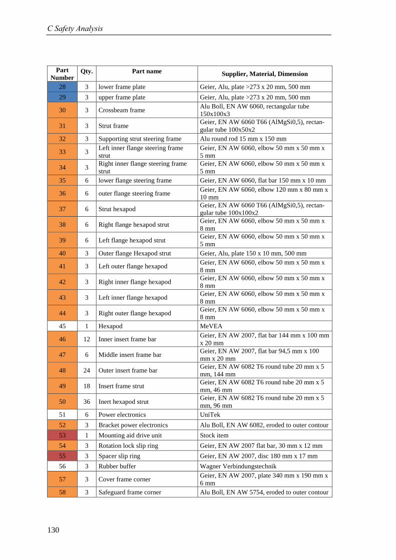
C Safety Analysis
130
Part
Number Qty. Part name Supplier, Material, Dimension
28 3 lower frame plate Geier, Alu, plate >273 x 20 mm, 500 mm
29 3 upper frame plate Geier, Alu, plate >273 x 20 mm, 500 mm
30 3 Crossbeam frame Alu Boll, EN AW 6060, rectangular tube
150x100x3
31 3 Strut frame Geier, EN AW 6060 T66 (AlMgSi0,5), rectan-
gular tube 100x50x2
32 3 Supporting strut steering frame Alu round rod 15 mm x 150 mm
33 3 Left inner flange steering frame
strut
Geier, EN AW 6060, elbow 50 mm x 50 mm x
5 mm
34 3 Right inner flange steering frame
strut
Geier, EN AW 6060, elbow 50 mm x 50 mm x
5 mm
35 6 lower flange steering frame Geier, EN AW 6060, flat bar 150 mm x 10 mm
36 6 outer flange steering frame Geier, EN AW 6060, elbow 120 mm x 80 mm x
10 mm
37 6 Strut hexapod Geier, EN AW 6060 T66 (AlMgSi0,5), rectan-
gular tube 100x100x2
38 6 Right flange hexapod strut Geier, EN AW 6060, elbow 50 mm x 50 mm x
8 mm
39 6 Left flange hexapod strut Geier, EN AW 6060, elbow 50 mm x 50 mm x
5 mm
40 3 Outer flange Hexapod strut Geier, Alu, plate 150 x 10 mm, 500 mm
41 3 Left outer flange hexapod Geier, EN AW 6060, elbow 50 mm x 50 mm x
8 mm
42 3 Right inner flange hexapod Geier, EN AW 6060, elbow 50 mm x 50 mm x
8 mm
43 3 Left inner flange hexapod Geier, EN AW 6060, elbow 50 mm x 50 mm x
8 mm
44 3 Right outer flange hexapod Geier, EN AW 6060, elbow 50 mm x 50 mm x
8 mm
45 1 Hexapod MeVEA
46 12 Inner insert frame bar Geier, EN AW 2007, flat bar 144 mm x 100 mm
x 20 mm
47 6 Middle insert frame bar Geier, EN AW 2007, flat bar 94,5 mm x 100
mm x 20 mm
48 24 Outer insert frame bar Geier, EN AW 6082 T6 round tube 20 mm x 5
mm, 144 mm
49 18 Insert frame strut Geier, EN AW 6082 T6 round tube 20 mm x 5
mm, 46 mm
50 36 Inert hexapod strut Geier, EN AW 6082 T6 round tube 20 mm x 5
mm, 96 mm
51 6 Power electronics UniTek
52 3 Bracket power electronics Alu Boll, EN AW 6082, eroded to outer contour
53 1 Mounting aid drive unit Stock item
54 3 Rotation lock slip ring Geier, EN AW 2007 flat bar, 30 mm x 12 mm
55 3 Spacer slip ring Geier, EN AW 2007, disc 180 mm x 17 mm
56 3 Rubber buffer Wagner Verbindungstechnik
57 3 Cover frame corner Geier, EN AW 2007, plate 340 mm x 190 mm x
6 mm
58 3 Safeguard frame corner Alu Boll, EN AW 5754, eroded to outer contour
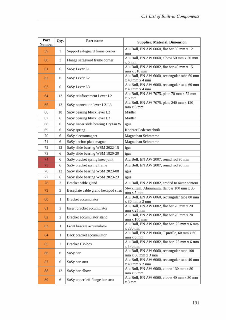
C.1 List of Built-in Components
131
Part
Number Qty. Part name Supplier, Material, Dimension
59 3 Support safeguard frame corner Alu Boll, EN AW 6060, flat bar 30 mm x 12
mm
60 3 Flange safeguard frame corner Alu Boll, EN AW 6060, elbow 50 mm x 50 mm
x 5 mm
61 6 SaSy Lever L1 Alu Boll, EN AW 6082, flat bar 40 mm x 15
mm x 310 mm
62 6 SaSy Lever L2 Alu Boll, EN AW 6060, rectangular tube 60 mm
x 40 mm x 4 mm
63 6 SaSy Lever L3 Alu Boll, EN AW 6060, rectangular tube 60 mm
x 40 mm x 4 mm
64 12 SaSy reinforcement Lever L2 Alu Boll, EN AW 7075, plate 70 mm x 52 mm
x 6 mm
65 12 SaSy connection lever L2-L3 Alu Boll, EN AW 7075, plate 240 mm x 120
mm x 6 mm
66 18 SaSy bearing block lever L2 Mädler
67 6 SaSy bearing block lever L3 Mädler
68 6 SaSy linear slide bearing DryLin W igus
69 6 SaSy spring Knörzer Federntechnik
70 6 SaSy electromagnet Magnetbau Schramme
71 6 SaSy anchor plate magnet Magnetbau Schramme
72 12 SaSy slide bearing WSM 2022-15 igus
73 6 SaSy slide bearing WSM 1820-20 igus
74 6 SaSy bracket spring knee joint Alu Boll, EN AW 2007, round rod 90 mm
75 6 SaSy bracket spring frame Alu Boll, EN AW 2007, round rod 90 mm
76 12 SaSy slide bearing WSM 2023-08 igus
77 6 SaSy slide bearing WSM 2023-23 igus
78 3 Bracket cable gland Alu Boll, EN AW 6082, eroded to outer contour
79 3 Baseplate cable grand hexapod strut Stock item, Aluminium, flat bar 100 mm x 35
mm x 5 mm
80 1 Bracket accumulator Alu Boll, EN AW 6060, rectangular tube 80 mm
x 30 mm x 2 mm
81 2 Insert bracket accumulator Alu Boll, EN AW 6082, flat bar 70 mm x 20
mm x 25 mm
82 2 Bracket accumulator stand Alu Boll, EN AW 6082, flat bar 70 mm x 20
mm x 100 mm
83 1 Front bracket accumulator Alu Boll, EN AW 6082, flat bar, 25 mm x 6 mm
x 280 mm
84 1 Back bracket accumulator Alu Boll, EN AW 6060, T profile, 60 mm x 60
mm x 6 mm
85 2 Bracket HV-box Alu Boll, EN AW 6082, flat bar, 25 mm x 6 mm
x 175 mm
86 6 SaSy bar Alu Boll, EN AW 6060, rectangular tube 100
mm x 60 mm x 3 mm
87 6 SaSy bar strut Alu Boll, EN AW 6060, rectangular tube 40 mm
x 40 mm x 2 mm
88 12 SaSy bar elbow Alu Boll, EN AW 6060, elbow 130 mm x 80
mm x 6 mm
89 6 SaSy upper left flange bar strut Alu Boll, EN AW 6060, elbow 40 mm x 30 mm
x 3 mm
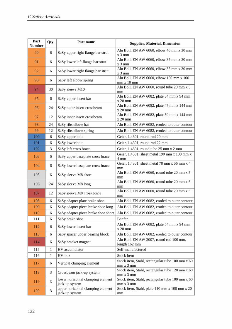
C Safety Analysis
132
Part
Number Qty. Part name Supplier, Material, Dimension
90 6 SaSy upper right flange bar strut Alu Boll, EN AW 6060, elbow 40 mm x 30 mm
x 3 mm
91 6 SaSy lower left flange bar strut Alu Boll, EN AW 6060, elbow 35 mm x 30 mm
x 3 mm
92 6 SaSy lower right flange bar strut Alu Boll, EN AW 6060, elbow 35 mm x 30 mm
x 3 mm
93 6 SaSy left elbow spring Alu Boll, EN AW 6060, elbow 150 mm x 100
mm x 10 mm
94 30 SaSy sleeve M10 Alu Boll, EN AW 6060, round tube 20 mm x 5
mm
95 6 SaSy upper insert bar Alu Boll, EN AW 6082, plate 54 mm x 94 mm
x 20 mm
96 24 SaSy outer insert crossbeam Alu Boll, EN AW 6082, plate 47 mm x 144 mm
x 20 mm
97 12 SaSy inner insert crossbeam Alu Boll, EN AW 6082, plate 50 mm x 144 mm
x 20 mm
98 24 SaSy ribs elbow bar Alu Boll, EN AW 6082, eroded to outer contour
99 12 SaSy ribs elbow spring Alu Boll, EN AW 6082, eroded to outer contour
100 6 SaSy upper bolt Geier, 1.4301, round rod 20 mm
101 6 SaSy lower bolt Geier, 1.4301, round rod 22 mm
102 3 SaSy left cross brace Geier, 1.4301, round tube 25 mm x 2 mm
103 6 SaSy upper baseplate cross brace Geier, 1.4301, sheet metal 190 mm x 100 mm x
4 mm
104 6 SaSy lower baseplate cross brace Geier, 1.4301, sheet metal 78 mm x 56 mm x 4
mm
105 6 SaSy sleeve M8 short Alu Boll, EN AW 6060, round tube 20 mm x 5
mm
106 24 SaSy sleeve M8 long Alu Boll, EN AW 6060, round tube 20 mm x 5
mm
107 12 SaSy sleeve M8 cross brace Alu Boll, EN AW 6060, round tube 20 mm x 5
mm
108 6 SaSy adapter plate brake shoe Alu Boll, EN AW 6082, eroded to outer contour
109 6 SaSy adapter piece brake shoe long Alu Boll, EN AW 6082, eroded to outer contour
110 6 SaSy adapter piece brake shoe short Alu Boll, EN AW 6082, eroded to outer contour
111 6 SaSy brake shoe Bänfer
112 6 SaSy lower insert bar Alu Boll, EN AW 6082, plate 54 mm x 94 mm
x 20 mm
113 6 SaSy spacer upper bearing block Alu Boll, EN AW 6082, eroded to outer contour
114 6 SaSy bracket magnet Alu Boll, EN AW 2007, round rod 100 mm,
length 162 mm
115 1 HV accumulator Self-manufactured
116 1 HV-box Stock item
117 6 Vertical clamping element Stock item, Stahl, rectangular tube 100 mm x 60
mm x 3 mm
118 3 Crossbeam jack-up system Stock item, Stahl, rectangular tube 120 mm x 60
mm x 3 mm
119 3 lower horizontal clamping element
jack-up system
Stock item, Stahl, rectangular tube 100 mm x 60
mm x 3 mm
120 3 upper horizontal clamping element
jack-up system
Stock item, Stahl, plate 110 mm x 100 mm x 20
mm
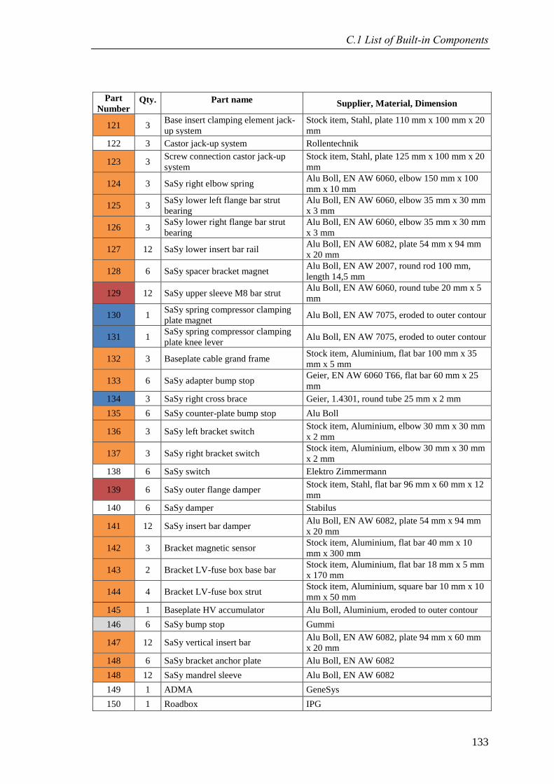
C.1 List of Built-in Components
133
Part
Number Qty. Part name Supplier, Material, Dimension
121 3 Base insert clamping element jack-
up system
Stock item, Stahl, plate 110 mm x 100 mm x 20
mm
122 3 Castor jack-up system Rollentechnik
123 3 Screw connection castor jack-up
system
Stock item, Stahl, plate 125 mm x 100 mm x 20
mm
124 3 SaSy right elbow spring Alu Boll, EN AW 6060, elbow 150 mm x 100
mm x 10 mm
125 3 SaSy lower left flange bar strut
bearing
Alu Boll, EN AW 6060, elbow 35 mm x 30 mm
x 3 mm
126 3 SaSy lower right flange bar strut
bearing
Alu Boll, EN AW 6060, elbow 35 mm x 30 mm
x 3 mm
127 12 SaSy lower insert bar rail Alu Boll, EN AW 6082, plate 54 mm x 94 mm
x 20 mm
128 6 SaSy spacer bracket magnet Alu Boll, EN AW 2007, round rod 100 mm,
length 14,5 mm
129 12 SaSy upper sleeve M8 bar strut Alu Boll, EN AW 6060, round tube 20 mm x 5
mm
130 1 SaSy spring compressor clamping
plate magnet Alu Boll, EN AW 7075, eroded to outer contour
131 1 SaSy spring compressor clamping
plate knee lever Alu Boll, EN AW 7075, eroded to outer contour
132 3 Baseplate cable grand frame Stock item, Aluminium, flat bar 100 mm x 35
mm x 5 mm
133 6 SaSy adapter bump stop Geier, EN AW 6060 T66, flat bar 60 mm x 25
mm
134 3 SaSy right cross brace Geier, 1.4301, round tube 25 mm x 2 mm
135 6 SaSy counter-plate bump stop Alu Boll
136 3 SaSy left bracket switch Stock item, Aluminium, elbow 30 mm x 30 mm
x 2 mm
137 3 SaSy right bracket switch Stock item, Aluminium, elbow 30 mm x 30 mm
x 2 mm
138 6 SaSy switch Elektro Zimmermann
139 6 SaSy outer flange damper Stock item, Stahl, flat bar 96 mm x 60 mm x 12
mm
140 6 SaSy damper Stabilus
141 12 SaSy insert bar damper Alu Boll, EN AW 6082, plate 54 mm x 94 mm
x 20 mm
142 3 Bracket magnetic sensor Stock item, Aluminium, flat bar 40 mm x 10
mm x 300 mm
143 2 Bracket LV-fuse box base bar Stock item, Aluminium, flat bar 18 mm x 5 mm
x 170 mm
144 4 Bracket LV-fuse box strut Stock item, Aluminium, square bar 10 mm x 10
mm x 50 mm
145 1 Baseplate HV accumulator Alu Boll, Aluminium, eroded to outer contour
146 6 SaSy bump stop Gummi
147 12 SaSy vertical insert bar Alu Boll, EN AW 6082, plate 94 mm x 60 mm
x 20 mm
148 6 SaSy bracket anchor plate Alu Boll, EN AW 6082
148 12 SaSy mandrel sleeve Alu Boll, EN AW 6082
149 1 ADMA GeneSys
150 1 Roadbox IPG
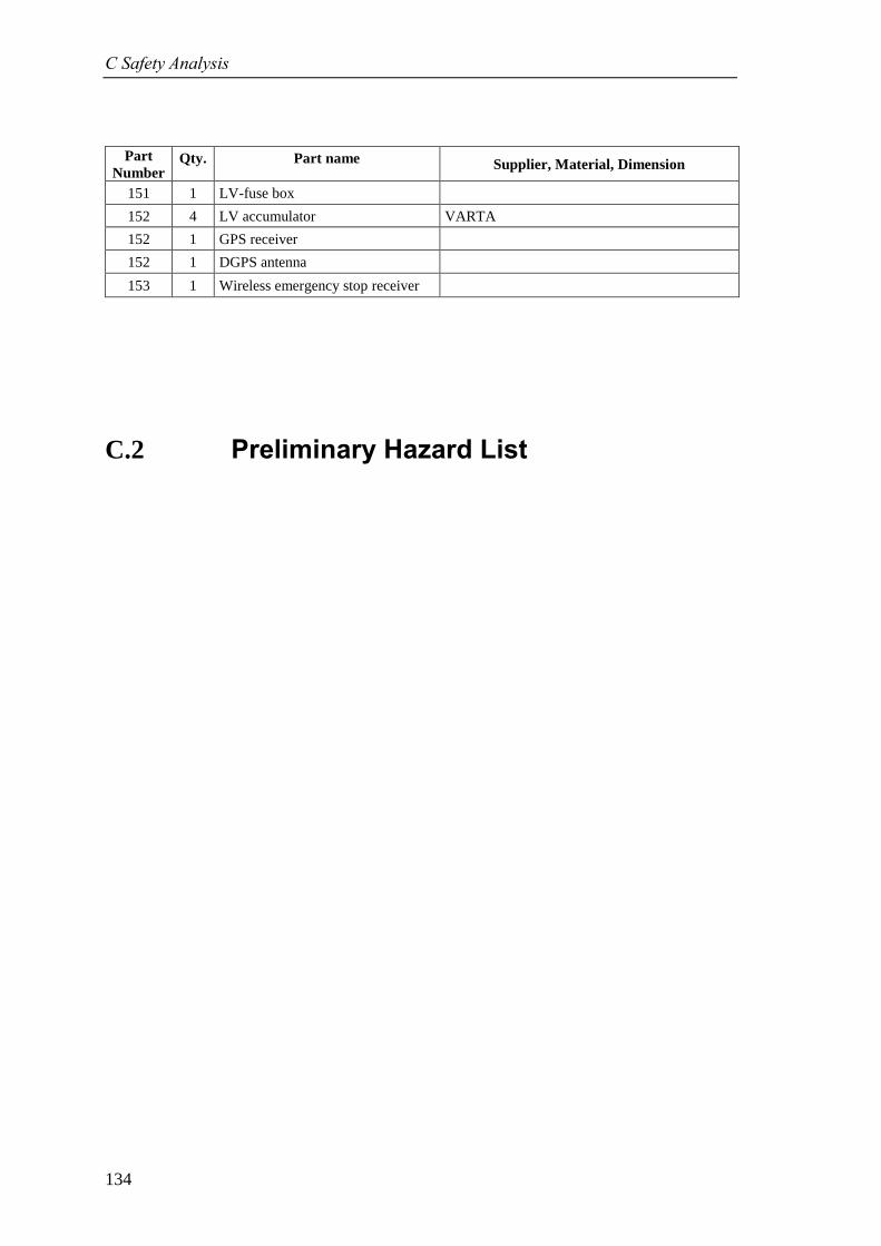
C Safety Analysis
134
Part
Number Qty. Part name Supplier, Material, Dimension
151 1 LV-fuse box
152 4 LV accumulator VARTA
152 1 GPS receiver
152 1 DGPS antenna
153 1 Wireless emergency stop receiver
C.2 Preliminary Hazard List
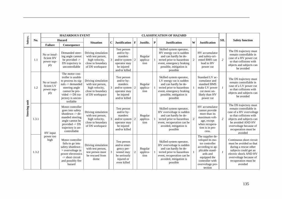
135
Su
bsy
s.
No.
HAZARDOUS EVENT CLASSIFICATION OF HAZARD
SIL Safety function Hazard Situation C Justification F Justific. P Justification W Justification
Failure Consequence
Ste
erin
g u
nit
1.1
No or insuf-
ficient HV
power sup-
ply
Demanded steer-
ing angle cannot
be provided ->
DS trajectory is
uncontrollable
Driving simulation
with test person,
high velocity,
close to boundary
of DS workspace
3
Test person
and/or by-
standers
and/or system
operator may
be injured
and/or killed
2
Regular
applica-
tion
1
Skilled system operator,
HV energy cut is sudden
and can hardly be de-
tected prior to hazardous
event, emergency braking
possible, mitigation is
possible
2
HV accumulator
and safety-ori-
ented BMS can
lead to HV
power cut
2
The DS trajectory must
remain controllable in
case of a HV power cut
so that collisions with
objects and subjects can
be avoided
1.2
No or insuf-
ficient LV
power sup-
ply
The motor con-
troller is unable
to process its sig-
nals -> demanded
steering angle
cannot be pro-
vided -> DS tra-
jectory is uncon-
trollable
Driving simulation
with test person,
high velocity,
close to boundary
of DS workspace
3
Test person
and/or by-
standers
and/or system
operator may
be injured
and/or killed
2
Regular
applica-
tion
1
Skilled system operator,
LV energy cut is sudden
and can hardly be de-
tected prior to hazardous
event, emergency braking
possible, mitigation is
possible
1
Standard LV ac-
cumulator and
standard BMS
make LV power
cut more un-
likely than HV
power cut
1
The DS trajectory must
remain controllable in
case of a LV power cut
so that collisions with
objects and subjects can
be avoided
1.3.1
HV input
power too
high
Motor controller
goes into safety
shutdown -> de-
manded steering
angle cannot be
provided -> DS
trajectory is un-
controllable
Driving simulation
with test person,
high velocity,
close to boundary
of DS workspace
3
Test person
and/or by-
standers
and/or system
operator may
be injured
and/or killed
2
Regular
applica-
tion
1
Skilled system operator,
HV overvoltage is sudden
and can hardly be de-
tected prior to hazardous
event, recuperation can be
avoided, mitigation is
possible
2
HV accumulator
cannot provide
more than its
maximum volt-
age, except
when recupera-
tion is in pro-
cess.
2
The DS trajectory must
remain controllable in
case of a HV overvoltage
so that collisions with
objects and subjects can
be avoided AND HV
overvoltage because of
recuperation must be
avoided
1.3.2
Motor controller
fails to go into
safety shutdown -
> overvoltage in
power electronics
-> short circuit
and possibly fire
hazard
Driving simulation
with test person,
test person must
be rescued from
dome
3
Test person
and/or emer-
gency per-
sonnel may
be seriously
injured or
even killed
2
Regular
applica-
tion
1
Skilled system operator,
HV overvoltage is sudden
and can hardly be de-
tected prior to hazardous
event, recuperation can be
avoided, mitigation is
possible
1
The supplier de-
veloped its mo-
tor controller
according to ap-
plicable stand-
ards and
equipped the
controller with
overvoltage pro-
tection
1
Continuous short circuit
must be avoided so that
during a rescue other
subjects could get an
electric shock AND HV
overvoltage because of
recuperation must be
avoided
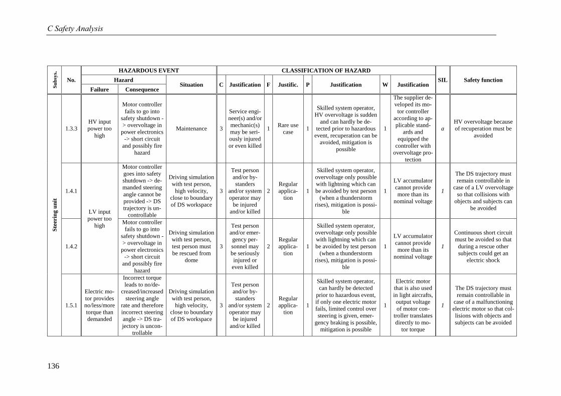
C Safety Analysis
136
Su
bsy
s.
No.
HAZARDOUS EVENT CLASSIFICATION OF HAZARD
SIL Safety function Hazard Situation C Justification F Justific. P Justification W Justification
Failure Consequence
Ste
erin
g u
nit
1.3.3
HV input
power too
high
Motor controller
fails to go into
safety shutdown -
> overvoltage in
power electronics
-> short circuit
and possibly fire
hazard
Maintenance 3
Service engi-
neer(s) and/or
mechanic(s)
may be seri-
ously injured
or even killed
1 Rare use
case 1
Skilled system operator,
HV overvoltage is sudden
and can hardly be de-
tected prior to hazardous
event, recuperation can be
avoided, mitigation is
possible
1
The supplier de-
veloped its mo-
tor controller
according to ap-
plicable stand-
ards and
equipped the
controller with
overvoltage pro-
tection
a
HV overvoltage because
of recuperation must be
avoided
1.4.1
LV input
power too
high
Motor controller
goes into safety
shutdown -> de-
manded steering
angle cannot be
provided -> DS
trajectory is un-
controllable
Driving simulation
with test person,
high velocity,
close to boundary
of DS workspace
3
Test person
and/or by-
standers
and/or system
operator may
be injured
and/or killed
2
Regular
applica-
tion
1
Skilled system operator,
overvoltage only possible
with lightning which can
be avoided by test person
(when a thunderstorm
rises), mitigation is possi-
ble
1
LV accumulator
cannot provide
more than its
nominal voltage
1
The DS trajectory must
remain controllable in
case of a LV overvoltage
so that collisions with
objects and subjects can
be avoided
1.4.2
Motor controller
fails to go into
safety shutdown -
> overvoltage in
power electronics
-> short circuit
and possibly fire
hazard
Driving simulation
with test person,
test person must
be rescued from
dome
3
Test person
and/or emer-
gency per-
sonnel may
be seriously
injured or
even killed
2
Regular
applica-
tion
1
Skilled system operator,
overvoltage only possible
with lightning which can
be avoided by test person
(when a thunderstorm
rises), mitigation is possi-
ble
1
LV accumulator
cannot provide
more than its
nominal voltage
1
Continuous short circuit
must be avoided so that
during a rescue other
subjects could get an
electric shock
1.5.1
Electric mo-
tor provides
no/less/more
torque than
demanded
Incorrect torque
leads to no/de-
creased/increased
steering angle
rate and therefore
incorrect steering
angle -> DS tra-
jectory is uncon-
trollable
Driving simulation
with test person,
high velocity,
close to boundary
of DS workspace
3
Test person
and/or by-
standers
and/or system
operator may
be injured
and/or killed
2
Regular
applica-
tion
1
Skilled system operator,
can hardly be detected
prior to hazardous event,
if only one electric motor
fails, limited control over
steering is given, emer-
gency braking is possible,
mitigation is possible
1
Electric motor
that is also used
in light aircrafts,
output voltage
of motor con-
troller translates
directly to mo-
tor torque
1
The DS trajectory must
remain controllable in
case of a malfunctioning
electric motor so that col-
lisions with objects and
subjects can be avoided
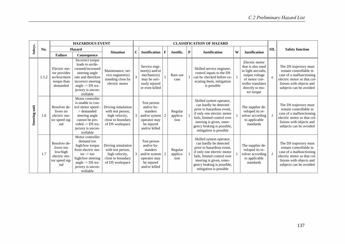
C.2 Preliminary Hazard List
137
Su
bsy
s.
No.
HAZARDOUS EVENT CLASSIFICATION OF HAZARD
SIL Safety function Hazard Situation C Justification F Justific. P Justification W Justification
Failure Consequence
Ste
erin
g u
nit
1.5.2
Electric mo-
tor provides
no/less/more
torque than
demanded
Incorrect torque
leads to no/de-
creased/increased
steering angle
rate and therefore
incorrect steering
angle -> DS tra-
jectory is uncon-
trollable
Maintenance, ser-
vice engineer(s)
standing close by
electric motor
3
Service engi-
neer(s) and/or
mechanic(s)
may be seri-
ously injured
or even killed
1 Rare use
case 1
Skilled service engineer,
control inputs to the DS
can be checked before ex-
ecuting them, mitigation
is possible
1
Electric motor
that is also used
in light aircrafts,
output voltage
of motor con-
troller translates
directly to mo-
tor torque
a
The DS trajectory must
remain controllable in
case of a malfunctioning
electric motor so that col-
lisions with objects and
subjects can be avoided
1.6
Resolver de-
livers no
electric mo-
tor speed sig-
nal
Motor controller
is unable to con-
trol motor speed -
> demanded
steering angle
cannot be pro-
vided -> DS tra-
jectory is uncon-
trollable
Driving simulation
with test person,
high velocity,
close to boundary
of DS workspace
3
Test person
and/or by-
standers
and/or system
operator may
be injured
and/or killed
2
Regular
applica-
tion
1
Skilled system operator,
can hardly be detected
prior to hazardous event,
if only one electric motor
fails, limited control over
steering is given, emer-
gency braking is possible,
mitigation is possible
1
The supplier de-
veloped its re-
solver according
to applicable
standards
1
The DS trajectory must
remain controllable in
case of a malfunctioning
electric motor so that col-
lisions with objects and
subjects can be avoided
1.7
Resolver de-
livers too
low/high
electric mo-
tor speed sig-
nal
Motor controller
demand too
high/low torque
from electric mo-
tor -> too
high/low steering
angle -> DS tra-
jectory is uncon-
trollable
Driving simulation
with test person,
high velocity,
close to boundary
of DS workspace
3
Test person
and/or by-
standers
and/or system
operator may
be injured
and/or killed
2
Regular
applica-
tion
1
Skilled system operator,
can hardly be detected
prior to hazardous event,
if only one electric motor
fails, limited control over
steering is given, emer-
gency braking is possible,
mitigation is possible
1
The supplier de-
veloped its re-
solver according
to applicable
standards
1
The DS trajectory must
remain controllable in
case of a malfunctioning
electric motor so that col-
lisions with objects and
subjects can be avoided
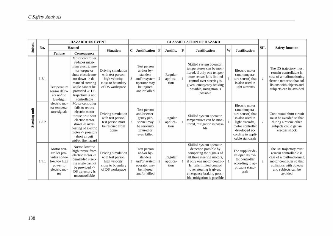
C Safety Analysis
138
Su
bsy
s.
No.
HAZARDOUS EVENT CLASSIFICATION OF HAZARD
SIL Safety function Hazard Situation C Justification F Justific. P Justification W Justification
Failure Consequence
Ste
erin
g u
nit
1.8.1
Temperature
sensor deliv-
ers no/too
low/high
electric mo-
tor tempera-
ture signals
Motor controller
reduces maxi-
mum electric mo-
tor torque or
shuts electric mo-
tor down -> de-
manded steering
angle cannot be
provided -> DS
trajectory is not
controllable
Driving simulation
with test person,
high velocity,
close to boundary
of DS workspace
3
Test person
and/or by-
standers
and/or system
operator may
be injured
and/or killed
2
Regular
applica-
tion
1
Skilled system operator,
temperatures can be mon-
itored, if only one temper-
ature sensor fails limited
control over steering is
given, emergency braking
possible, mitigation is
possible
1
Electric motor
(and tempera-
ture sensor) that
is also used in
light aircrafts
1
The DS trajectory must
remain controllable in
case of a malfunctioning
electric motor so that col-
lisions with objects and
subjects can be avoided
1.8.2
Motor controller
fails to reduce
electric motor
torque or to shut
electric motor
down -> over-
heating of electric
motor -> possibly
short circuit
and/or fire hazard
Driving simulation
with test person,
test person must
be rescued from
dome
3
Test person
and/or emer-
gency per-
sonnel may
be seriously
injured or
even killed
2
Regular
applica-
tion
1
Skilled system operator,
temperatures can be mon-
itored, mitigation is possi-
ble
1
Electric motor
(and tempera-
ture sensor) that
is also used in
light aircrafts,
motor controller
developed ac-
cording to appli-
cable standards
1
Continuous short circuit
must be avoided so that
during a rescue other
subjects could get an
electric shock
1.9.1
Motor con-
troller pro-
vides no/too
low/too high
power to
electric mo-
tor
No/too low/too
high torque from
electric motor ->
demanded steer-
ing angle cannot
be provided ->
DS trajectory is
uncontrollable
Driving simulation
with test person,
high velocity,
close to boundary
of DS workspace
3
Test person
and/or by-
standers
and/or system
operator may
be injured
and/or killed
2
Regular
applica-
tion
1
Skilled system operator,
detection possible by
comparing the signals of
all three steering motors,
if only one motor control-
ler fails limited control
over steering is given,
emergency braking possi-
ble, mitigation is possible
1
The supplier de-
veloped its mo-
tor controller
according to ap-
plicable stand-
ards
1
The DS trajectory must
remain controllable in
case of a malfunctioning
motor controller so that
collisions with objects
and subjects can be
avoided
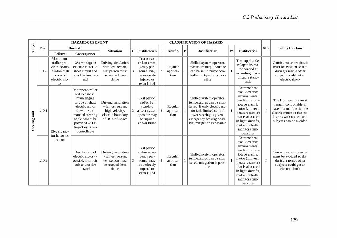
C.2 Preliminary Hazard List
139
Su
bsy
s.
No.
HAZARDOUS EVENT CLASSIFICATION OF HAZARD
SIL Safety function Hazard Situation C Justification F Justific. P Justification W Justification
Failure Consequence
Ste
erin
g u
nit
1.9.2
Motor con-
troller pro-
vides no/too
low/too high
power to
electric mo-
tor
Overvoltage in
electric motor ->
short circuit and
possibly fire haz-
ard
Driving simulation
with test person,
test person must
be rescued from
dome
3
Test person
and/or emer-
gency per-
sonnel may
be seriously
injured or
even killed
2
Regular
applica-
tion
1
Skilled system operator,
maximum output voltage
can be set in motor con-
troller, mitigation is pos-
sible
1
The supplier de-
veloped its mo-
tor controller
according to ap-
plicable stand-
ards
1
Continuous short circuit
must be avoided so that
during a rescue other
subjects could get an
electric shock
1.10.1
Electric mo-
tor becomes
too hot
Motor controller
reduces maxi-
mum engine
torque or shuts
electric motor
down -> de-
manded steering
angle cannot be
provided -> DS
trajectory is un-
controllable
Driving simulation
with test person,
high velocity,
close to boundary
of DS workspace
3
Test person
and/or by-
standers
and/or system
operator may
be injured
and/or killed
2
Regular
applica-
tion
1
Skilled system operator,
temperatures can be mon-
itored, if only electric mo-
tor fails limited control
over steering is given,
emergency braking possi-
ble, mitigation is possible
1
Extreme heat
excluded from
environmental
conditions, pro-
totype electric
motor (and tem-
perature sensor)
that is also used
in light aircrafts,
motor controller
monitors tem-
peratures
1
The DS trajectory must
remain controllable in
case of a malfunctioning
electric motor so that col-
lisions with objects and
subjects can be avoided
1.10.2
Overheating of
electric motor ->
possibly short cir-
cuit and/or fire
hazard
Driving simulation
with test person,
test person must
be rescued from
dome
3
Test person
and/or emer-
gency per-
sonnel may
be seriously
injured or
even killed
2
Regular
applica-
tion
1
Skilled system operator,
temperatures can be mon-
itored, mitigation is possi-
ble
1
Extreme heat
excluded from
environmental
conditions, pro-
totype electric
motor (and tem-
perature sensor)
that is also used
in light aircrafts,
motor controller
monitors tem-
peratures
1
Continuous short circuit
must be avoided so that
during a rescue other
subjects could get an
electric shock
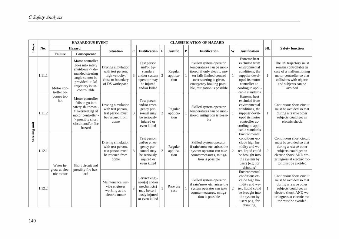
C Safety Analysis
140
Su
bsy
s.
No.
HAZARDOUS EVENT CLASSIFICATION OF HAZARD
SIL Safety function Hazard Situation C Justification F Justific. P Justification W Justification
Failure Consequence
Ste
erin
g u
nit
1.11.1
Motor con-
troller be-
comes too
hot
Motor controller
goes into safety
shutdown -> de-
manded steering
angle cannot be
provided -> DS
trajectory is un-
controllable
Driving simulation
with test person,
high velocity,
close to boundary
of DS workspace
3
Test person
and/or by-
standers
and/or system
operator may
be injured
and/or killed
2
Regular
applica-
tion
1
Skilled system operator,
temperatures can be mon-
itored, if only electric mo-
tor fails limited control
over steering is given,
emergency braking possi-
ble, mitigation is possible
1
Extreme heat
excluded from
environmental
conditions, the
supplier devel-
oped its motor
controller ac-
cording to appli-
cable standards
1
The DS trajectory must
remain controllable in
case of a malfunctioning
motor controller so that
collisions with objects
and subjects can be
avoided
1.11.2
Motor controller
fails to go into
safety shutdown -
> overheating of
motor controller -
> possibly short
circuit and/or fire
hazard
Driving simulation
with test person,
test person must
be rescued from
dome
3
Test person
and/or emer-
gency per-
sonnel may
be seriously
injured or
even killed
2
Regular
applica-
tion
1
Skilled system operator,
temperatures can be mon-
itored, mitigation is possi-
ble
1
Extreme heat
excluded from
environmental
conditions, the
supplier devel-
oped its motor
controller ac-
cording to appli-
cable standards
1
Continuous short circuit
must be avoided so that
during a rescue other
subjects could get an
electric shock
1.12.1
Water in-
gress at elec-
tric motor
Short circuit and
possibly fire haz-
ard
Driving simulation
with test person,
test person must
be rescued from
dome
3
Test person
and/or emer-
gency per-
sonnel may
be seriously
injured or
even killed
2
Regular
applica-
tion
1
Skilled system operator,
if rain/snow etc. arises the
system operator can take
countermeasures, mitiga-
tion is possible
2
Environmental
conditions ex-
clude high hu-
midity and wa-
ter, liquid could
be brought into
the system by
users (e.g. for
drinking)
2
Continuous short circuit
must be avoided so that
during a rescue other
subjects could get an
electric shock AND wa-
ter ingress at electric mo-
tor must be avoided
1.12.2
Maintenance, ser-
vice engineer
working at the
electric motor
3
Service engi-
neer(s) and/or
mechanic(s)
may be seri-
ously injured
or even killed
1 Rare use
case 1
Skilled system operator,
if rain/snow etc. arises the
system operator can take
countermeasures, mitiga-
tion is possible
2
Environmental
conditions ex-
clude high hu-
midity and wa-
ter, liquid could
be brought into
the system by
users (e.g. for
drinking)
1
Continuous short circuit
must be avoided so that
during a rescue other
subjects could get an
electric shock AND wa-
ter ingress at electric mo-
tor must be avoided
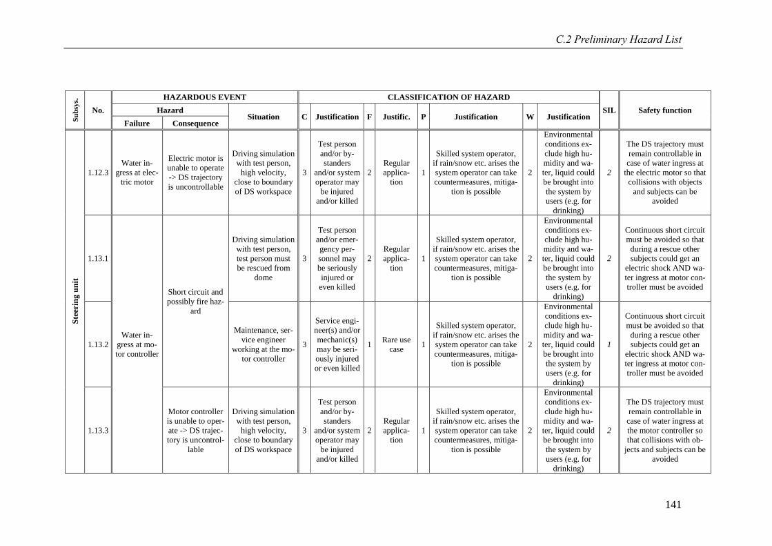
C.2 Preliminary Hazard List
141
Su
bsy
s.
No.
HAZARDOUS EVENT CLASSIFICATION OF HAZARD
SIL Safety function Hazard Situation C Justification F Justific. P Justification W Justification
Failure Consequence
Ste
erin
g u
nit
1.12.3
Water in-
gress at elec-
tric motor
Electric motor is
unable to operate
-> DS trajectory
is uncontrollable
Driving simulation
with test person,
high velocity,
close to boundary
of DS workspace
3
Test person
and/or by-
standers
and/or system
operator may
be injured
and/or killed
2
Regular
applica-
tion
1
Skilled system operator,
if rain/snow etc. arises the
system operator can take
countermeasures, mitiga-
tion is possible
2
Environmental
conditions ex-
clude high hu-
midity and wa-
ter, liquid could
be brought into
the system by
users (e.g. for
drinking)
2
The DS trajectory must
remain controllable in
case of water ingress at
the electric motor so that
collisions with objects
and subjects can be
avoided
1.13.1
Water in-
gress at mo-
tor controller
Short circuit and
possibly fire haz-
ard
Driving simulation
with test person,
test person must
be rescued from
dome
3
Test person
and/or emer-
gency per-
sonnel may
be seriously
injured or
even killed
2
Regular
applica-
tion
1
Skilled system operator,
if rain/snow etc. arises the
system operator can take
countermeasures, mitiga-
tion is possible
2
Environmental
conditions ex-
clude high hu-
midity and wa-
ter, liquid could
be brought into
the system by
users (e.g. for
drinking)
2
Continuous short circuit
must be avoided so that
during a rescue other
subjects could get an
electric shock AND wa-
ter ingress at motor con-
troller must be avoided
1.13.2
Maintenance, ser-
vice engineer
working at the mo-
tor controller
3
Service engi-
neer(s) and/or
mechanic(s)
may be seri-
ously injured
or even killed
1 Rare use
case 1
Skilled system operator,
if rain/snow etc. arises the
system operator can take
countermeasures, mitiga-
tion is possible
2
Environmental
conditions ex-
clude high hu-
midity and wa-
ter, liquid could
be brought into
the system by
users (e.g. for
drinking)
1
Continuous short circuit
must be avoided so that
during a rescue other
subjects could get an
electric shock AND wa-
ter ingress at motor con-
troller must be avoided
1.13.3
Motor controller
is unable to oper-
ate -> DS trajec-
tory is uncontrol-
lable
Driving simulation
with test person,
high velocity,
close to boundary
of DS workspace
3
Test person
and/or by-
standers
and/or system
operator may
be injured
and/or killed
2
Regular
applica-
tion
1
Skilled system operator,
if rain/snow etc. arises the
system operator can take
countermeasures, mitiga-
tion is possible
2
Environmental
conditions ex-
clude high hu-
midity and wa-
ter, liquid could
be brought into
the system by
users (e.g. for
drinking)
2
The DS trajectory must
remain controllable in
case of water ingress at
the motor controller so
that collisions with ob-
jects and subjects can be
avoided
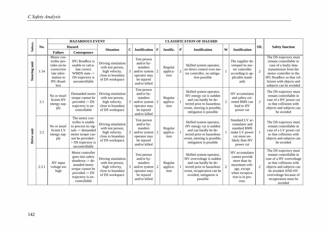
C Safety Analysis
142
Su
bsy
s.
No.
HAZARDOUS EVENT CLASSIFICATION OF HAZARD
SIL Safety function Hazard Situation C Justification F Justific. P Justification W Justification
Failure Consequence
Ste
erin
g u
nit
1.14
Motor con-
troller pro-
vides no/in-
correct/too
late infor-
mation to
IPG Road-
box
IPG Roadbox is
unable to calcu-
late correct
WMDS state ->
DS trajectory is
uncontrollable
Driving simulation
with test person,
high velocity,
close to boundary
of DS workspace
3
Test person
and/or by-
standers
and/or system
operator may
be injured
and/or killed
2
Regular
applica-
tion
2
Skilled system operator,
no direct control over mo-
tor controller, no mitiga-
tion possible
1
The supplier de-
veloped its mo-
tor controller
according to ap-
plicable stand-
ards
2
The DS trajectory must
remain controllable in
case of a faulty data
transmission from the
motor controller to the
IPG Roadbox so that col-
lisions with objects and
subjects can be avoided
Dri
ve
un
it
2.1
No or insuf-
ficient HV
energy sup-
ply
Demanded motor
torque cannot be
provided -> DS
trajectory is un-
controllable
Driving simulation
with test person,
high velocity,
close to boundary
of DS workspace
3
Test person
and/or by-
standers
and/or system
operator may
be injured
and/or killed
2
Regular
applica-
tion
1
Skilled system operator,
HV energy cut is sudden
and can hardly be de-
tected prior to hazardous
event, steering is possible,
mitigation is possible
2
HV accumulator
and safety-ori-
ented BMS can
lead to HV
power cut
2
The DS trajectory must
remain controllable in
case of a HV power cut
so that collisions with
objects and subjects can
be avoided
2.2
No or insuf-
ficient LV
energy sup-
ply
The motor con-
troller is unable
to process its sig-
nals -> demanded
motor torque can-
not be provided -
> DS trajectory is
uncontrollable
Driving simulation
with test person,
high velocity,
close to boundary
of DS workspace
3
Test person
and/or by-
standers
and/or system
operator may
be injured
and/or killed
2
Regular
applica-
tion
1
Skilled system operator,
HV energy cut is sudden
and can hardly be de-
tected prior to hazardous
event, steering is possible,
mitigation is possible
1
Standard LV ac-
cumulator and
standard BMS
make LV power
cut more un-
likely than HV
power cut
1
The DS trajectory must
remain controllable in
case of a LV power cut
so that collisions with
objects and subjects can
be avoided
2.3.1
HV input
voltage too
high
Motor controller
goes into safety
shutdown -> de-
manded motor
torque cannot be
provided -> DS
trajectory is un-
controllable
Driving simulation
with test person,
high velocity,
close to boundary
of DS workspace
3
Test person
and/or by-
standers
and/or system
operator may
be injured
and/or killed
2
Regular
applica-
tion
1
Skilled system operator,
HV overvoltage is sudden
and can hardly be de-
tected prior to hazardous
event, recuperation can be
avoided, mitigation is
possible
2
HV accumulator
cannot provide
more than its
maximum volt-
age, except
when recupera-
tion is in pro-
cess.
2
The DS trajectory must
remain controllable in
case of a HV overvoltage
so that collisions with
objects and subjects can
be avoided AND HV
overvoltage because of
recuperation must be
avoided
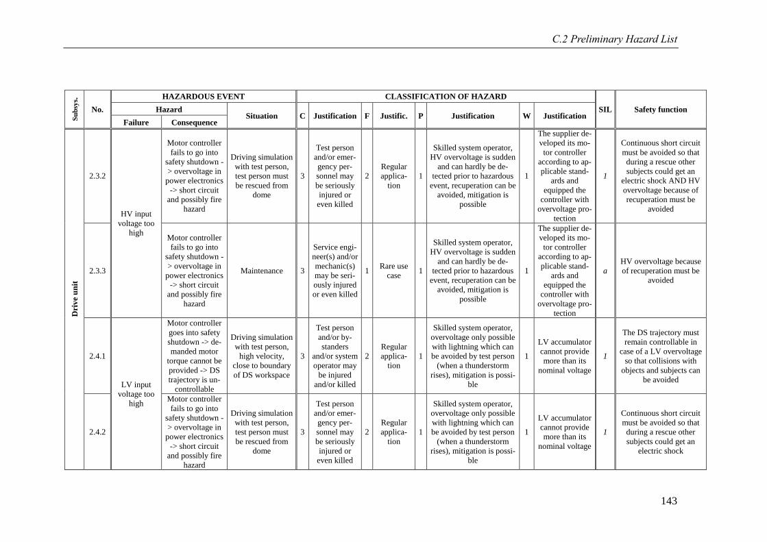
C.2 Preliminary Hazard List
143
Su
bsy
s.
No.
HAZARDOUS EVENT CLASSIFICATION OF HAZARD
SIL Safety function Hazard Situation C Justification F Justific. P Justification W Justification
Failure Consequence
Dri
ve
un
it
2.3.2
HV input
voltage too
high
Motor controller
fails to go into
safety shutdown -
> overvoltage in
power electronics
-> short circuit
and possibly fire
hazard
Driving simulation
with test person,
test person must
be rescued from
dome
3
Test person
and/or emer-
gency per-
sonnel may
be seriously
injured or
even killed
2
Regular
applica-
tion
1
Skilled system operator,
HV overvoltage is sudden
and can hardly be de-
tected prior to hazardous
event, recuperation can be
avoided, mitigation is
possible
1
The supplier de-
veloped its mo-
tor controller
according to ap-
plicable stand-
ards and
equipped the
controller with
overvoltage pro-
tection
1
Continuous short circuit
must be avoided so that
during a rescue other
subjects could get an
electric shock AND HV
overvoltage because of
recuperation must be
avoided
2.3.3
Motor controller
fails to go into
safety shutdown -
> overvoltage in
power electronics
-> short circuit
and possibly fire
hazard
Maintenance 3
Service engi-
neer(s) and/or
mechanic(s)
may be seri-
ously injured
or even killed
1 Rare use
case 1
Skilled system operator,
HV overvoltage is sudden
and can hardly be de-
tected prior to hazardous
event, recuperation can be
avoided, mitigation is
possible
1
The supplier de-
veloped its mo-
tor controller
according to ap-
plicable stand-
ards and
equipped the
controller with
overvoltage pro-
tection
a
HV overvoltage because
of recuperation must be
avoided
2.4.1
LV input
voltage too
high
Motor controller
goes into safety
shutdown -> de-
manded motor
torque cannot be
provided -> DS
trajectory is un-
controllable
Driving simulation
with test person,
high velocity,
close to boundary
of DS workspace
3
Test person
and/or by-
standers
and/or system
operator may
be injured
and/or killed
2
Regular
applica-
tion
1
Skilled system operator,
overvoltage only possible
with lightning which can
be avoided by test person
(when a thunderstorm
rises), mitigation is possi-
ble
1
LV accumulator
cannot provide
more than its
nominal voltage
1
The DS trajectory must
remain controllable in
case of a LV overvoltage
so that collisions with
objects and subjects can
be avoided
2.4.2
Motor controller
fails to go into
safety shutdown -
> overvoltage in
power electronics
-> short circuit
and possibly fire
hazard
Driving simulation
with test person,
test person must
be rescued from
dome
3
Test person
and/or emer-
gency per-
sonnel may
be seriously
injured or
even killed
2
Regular
applica-
tion
1
Skilled system operator,
overvoltage only possible
with lightning which can
be avoided by test person
(when a thunderstorm
rises), mitigation is possi-
ble
1
LV accumulator
cannot provide
more than its
nominal voltage
1
Continuous short circuit
must be avoided so that
during a rescue other
subjects could get an
electric shock
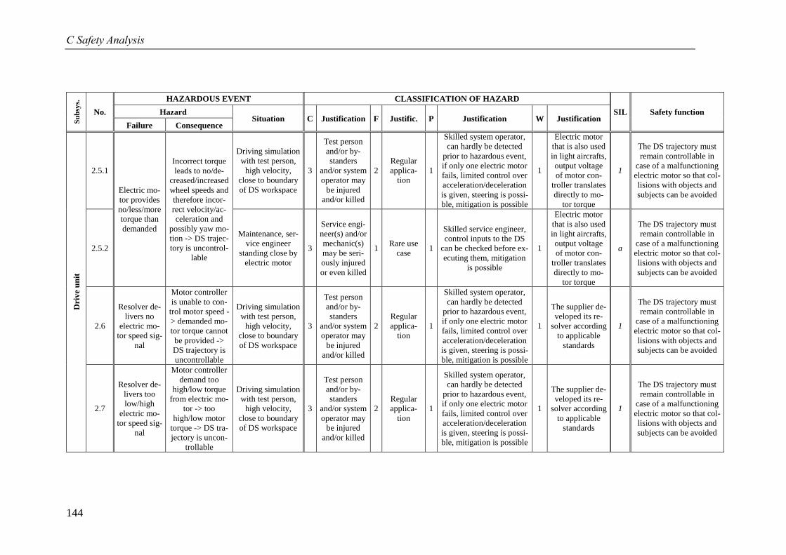
C Safety Analysis
144
Su
bsy
s.
No.
HAZARDOUS EVENT CLASSIFICATION OF HAZARD
SIL Safety function Hazard Situation C Justification F Justific. P Justification W Justification
Failure Consequence
Dri
ve
un
it
2.5.1
Electric mo-
tor provides
no/less/more
torque than
demanded
Incorrect torque
leads to no/de-
creased/increased
wheel speeds and
therefore incor-
rect velocity/ac-
celeration and
possibly yaw mo-
tion -> DS trajec-
tory is uncontrol-
lable
Driving simulation
with test person,
high velocity,
close to boundary
of DS workspace
3
Test person
and/or by-
standers
and/or system
operator may
be injured
and/or killed
2
Regular
applica-
tion
1
Skilled system operator,
can hardly be detected
prior to hazardous event,
if only one electric motor
fails, limited control over
acceleration/deceleration
is given, steering is possi-
ble, mitigation is possible
1
Electric motor
that is also used
in light aircrafts,
output voltage
of motor con-
troller translates
directly to mo-
tor torque
1
The DS trajectory must
remain controllable in
case of a malfunctioning
electric motor so that col-
lisions with objects and
subjects can be avoided
2.5.2
Maintenance, ser-
vice engineer
standing close by
electric motor
3
Service engi-
neer(s) and/or
mechanic(s)
may be seri-
ously injured
or even killed
1 Rare use
case 1
Skilled service engineer,
control inputs to the DS
can be checked before ex-
ecuting them, mitigation
is possible
1
Electric motor
that is also used
in light aircrafts,
output voltage
of motor con-
troller translates
directly to mo-
tor torque
a
The DS trajectory must
remain controllable in
case of a malfunctioning
electric motor so that col-
lisions with objects and
subjects can be avoided
2.6
Resolver de-
livers no
electric mo-
tor speed sig-
nal
Motor controller
is unable to con-
trol motor speed -
> demanded mo-
tor torque cannot
be provided ->
DS trajectory is
uncontrollable
Driving simulation
with test person,
high velocity,
close to boundary
of DS workspace
3
Test person
and/or by-
standers
and/or system
operator may
be injured
and/or killed
2
Regular
applica-
tion
1
Skilled system operator,
can hardly be detected
prior to hazardous event,
if only one electric motor
fails, limited control over
acceleration/deceleration
is given, steering is possi-
ble, mitigation is possible
1
The supplier de-
veloped its re-
solver according
to applicable
standards
1
The DS trajectory must
remain controllable in
case of a malfunctioning
electric motor so that col-
lisions with objects and
subjects can be avoided
2.7
Resolver de-
livers too
low/high
electric mo-
tor speed sig-
nal
Motor controller
demand too
high/low torque
from electric mo-
tor -> too
high/low motor
torque -> DS tra-
jectory is uncon-
trollable
Driving simulation
with test person,
high velocity,
close to boundary
of DS workspace
3
Test person
and/or by-
standers
and/or system
operator may
be injured
and/or killed
2
Regular
applica-
tion
1
Skilled system operator,
can hardly be detected
prior to hazardous event,
if only one electric motor
fails, limited control over
acceleration/deceleration
is given, steering is possi-
ble, mitigation is possible
1
The supplier de-
veloped its re-
solver according
to applicable
standards
1
The DS trajectory must
remain controllable in
case of a malfunctioning
electric motor so that col-
lisions with objects and
subjects can be avoided
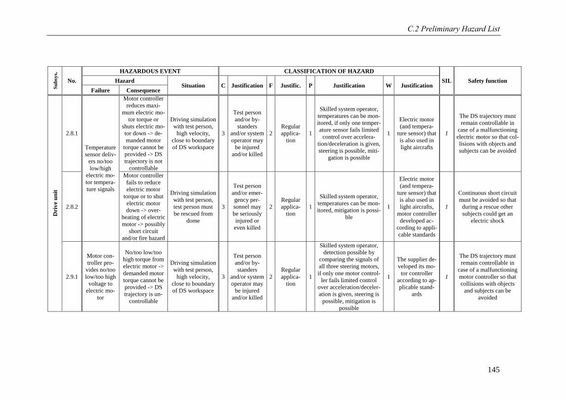
C.2 Preliminary Hazard List
145
Su
bsy
s.
No.
HAZARDOUS EVENT CLASSIFICATION OF HAZARD
SIL Safety function Hazard Situation C Justification F Justific. P Justification W Justification
Failure Consequence
Dri
ve
un
it
2.8.1
Temperature
sensor deliv-
ers no/too
low/high
electric mo-
tor tempera-
ture signals
Motor controller
reduces maxi-
mum electric mo-
tor torque or
shuts electric mo-
tor down -> de-
manded motor
torque cannot be
provided -> DS
trajectory is not
controllable
Driving simulation
with test person,
high velocity,
close to boundary
of DS workspace
3
Test person
and/or by-
standers
and/or system
operator may
be injured
and/or killed
2
Regular
applica-
tion
1
Skilled system operator,
temperatures can be mon-
itored, if only one temper-
ature sensor fails limited
control over accelera-
tion/deceleration is given,
steering is possible, miti-
gation is possible
1
Electric motor
(and tempera-
ture sensor) that
is also used in
light aircrafts
1
The DS trajectory must
remain controllable in
case of a malfunctioning
electric motor so that col-
lisions with objects and
subjects can be avoided
2.8.2
Motor controller
fails to reduce
electric motor
torque or to shut
electric motor
down -> over-
heating of electric
motor -> possibly
short circuit
and/or fire hazard
Driving simulation
with test person,
test person must
be rescued from
dome
3
Test person
and/or emer-
gency per-
sonnel may
be seriously
injured or
even killed
2
Regular
applica-
tion
1
Skilled system operator,
temperatures can be mon-
itored, mitigation is possi-
ble
1
Electric motor
(and tempera-
ture sensor) that
is also used in
light aircrafts,
motor controller
developed ac-
cording to appli-
cable standards
1
Continuous short circuit
must be avoided so that
during a rescue other
subjects could get an
electric shock
2.9.1
Motor con-
troller pro-
vides no/too
low/too high
voltage to
electric mo-
tor
No/too low/too
high torque from
electric motor ->
demanded motor
torque cannot be
provided -> DS
trajectory is un-
controllable
Driving simulation
with test person,
high velocity,
close to boundary
of DS workspace
3
Test person
and/or by-
standers
and/or system
operator may
be injured
and/or killed
2
Regular
applica-
tion
1
Skilled system operator,
detection possible by
comparing the signals of
all three steering motors,
if only one motor control-
ler fails limited control
over acceleration/deceler-
ation is given, steering is
possible, mitigation is
possible
1
The supplier de-
veloped its mo-
tor controller
according to ap-
plicable stand-
ards
1
The DS trajectory must
remain controllable in
case of a malfunctioning
motor controller so that
collisions with objects
and subjects can be
avoided
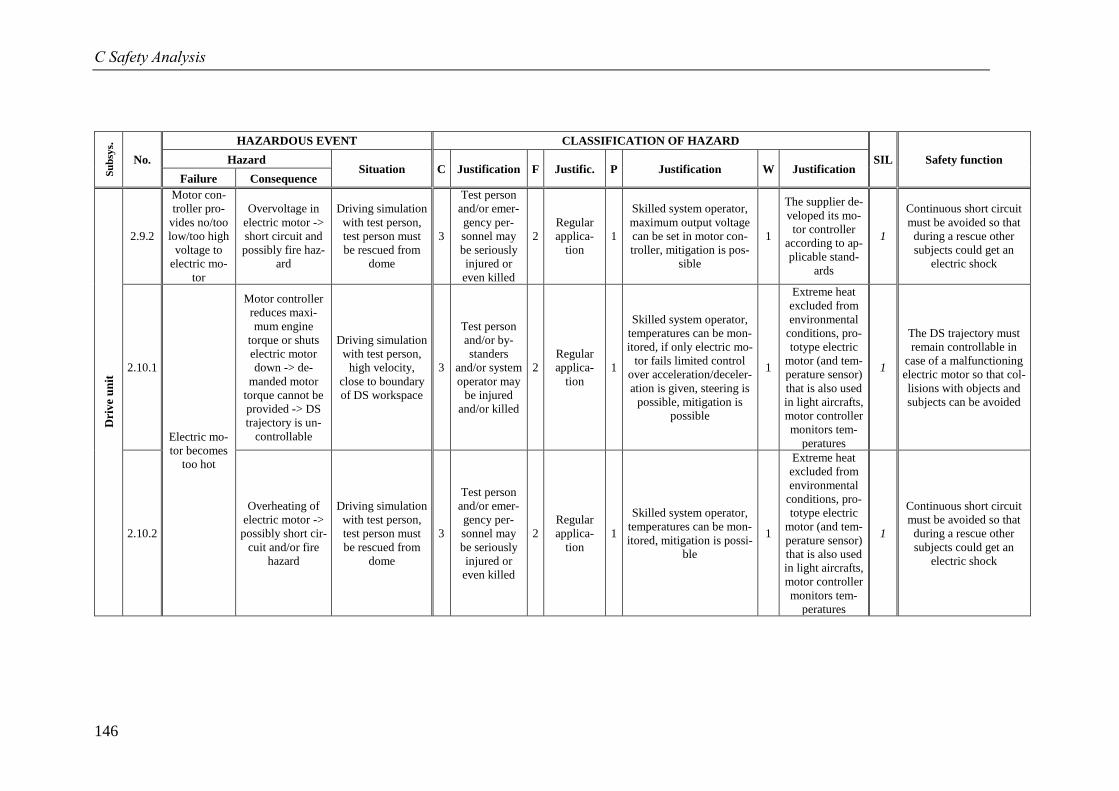
C Safety Analysis
146
Su
bsy
s.
No.
HAZARDOUS EVENT CLASSIFICATION OF HAZARD
SIL Safety function Hazard Situation C Justification F Justific. P Justification W Justification
Failure Consequence
Dri
ve
un
it
2.9.2
Motor con-
troller pro-
vides no/too
low/too high
voltage to
electric mo-
tor
Overvoltage in
electric motor ->
short circuit and
possibly fire haz-
ard
Driving simulation
with test person,
test person must
be rescued from
dome
3
Test person
and/or emer-
gency per-
sonnel may
be seriously
injured or
even killed
2
Regular
applica-
tion
1
Skilled system operator,
maximum output voltage
can be set in motor con-
troller, mitigation is pos-
sible
1
The supplier de-
veloped its mo-
tor controller
according to ap-
plicable stand-
ards
1
Continuous short circuit
must be avoided so that
during a rescue other
subjects could get an
electric shock
2.10.1
Electric mo-
tor becomes
too hot
Motor controller
reduces maxi-
mum engine
torque or shuts
electric motor
down -> de-
manded motor
torque cannot be
provided -> DS
trajectory is un-
controllable
Driving simulation
with test person,
high velocity,
close to boundary
of DS workspace
3
Test person
and/or by-
standers
and/or system
operator may
be injured
and/or killed
2
Regular
applica-
tion
1
Skilled system operator,
temperatures can be mon-
itored, if only electric mo-
tor fails limited control
over acceleration/deceler-
ation is given, steering is
possible, mitigation is
possible
1
Extreme heat
excluded from
environmental
conditions, pro-
totype electric
motor (and tem-
perature sensor)
that is also used
in light aircrafts,
motor controller
monitors tem-
peratures
1
The DS trajectory must
remain controllable in
case of a malfunctioning
electric motor so that col-
lisions with objects and
subjects can be avoided
2.10.2
Overheating of
electric motor ->
possibly short cir-
cuit and/or fire
hazard
Driving simulation
with test person,
test person must
be rescued from
dome
3
Test person
and/or emer-
gency per-
sonnel may
be seriously
injured or
even killed
2
Regular
applica-
tion
1
Skilled system operator,
temperatures can be mon-
itored, mitigation is possi-
ble
1
Extreme heat
excluded from
environmental
conditions, pro-
totype electric
motor (and tem-
perature sensor)
that is also used
in light aircrafts,
motor controller
monitors tem-
peratures
1
Continuous short circuit
must be avoided so that
during a rescue other
subjects could get an
electric shock
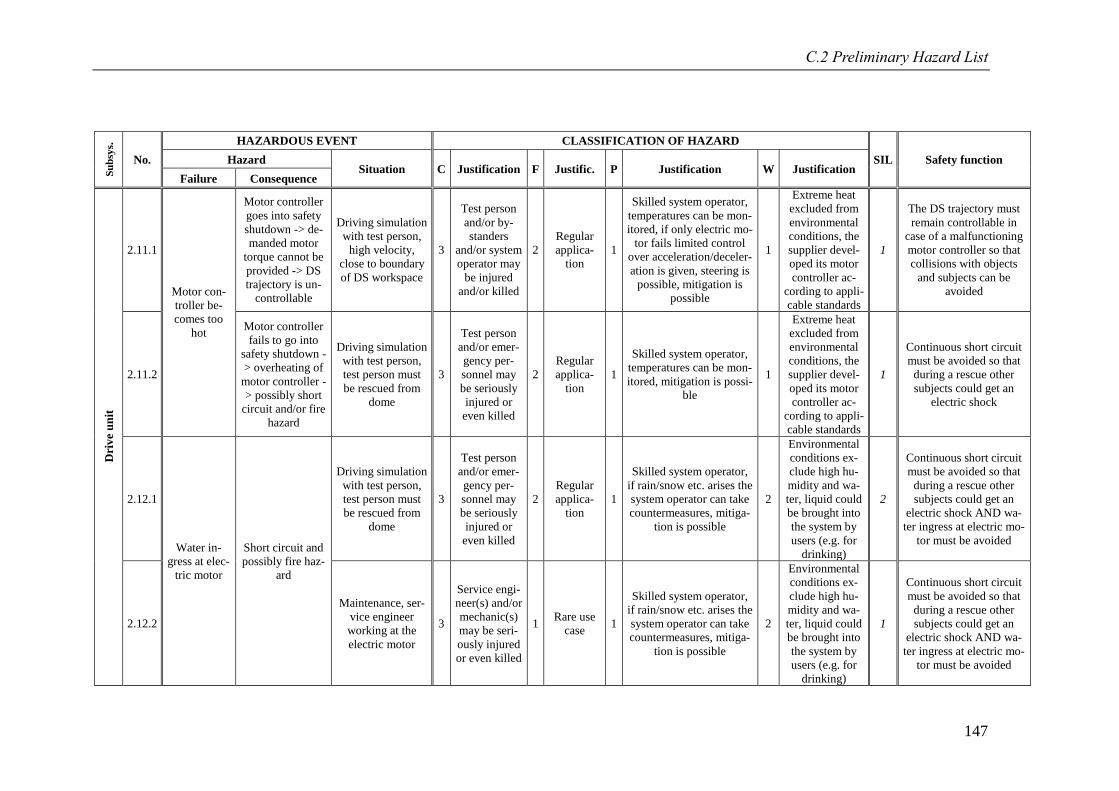
C.2 Preliminary Hazard List
147
Su
bsy
s.
No.
HAZARDOUS EVENT CLASSIFICATION OF HAZARD
SIL Safety function Hazard Situation C Justification F Justific. P Justification W Justification
Failure Consequence
Dri
ve
un
it
2.11.1
Motor con-
troller be-
comes too
hot
Motor controller
goes into safety
shutdown -> de-
manded motor
torque cannot be
provided -> DS
trajectory is un-
controllable
Driving simulation
with test person,
high velocity,
close to boundary
of DS workspace
3
Test person
and/or by-
standers
and/or system
operator may
be injured
and/or killed
2
Regular
applica-
tion
1
Skilled system operator,
temperatures can be mon-
itored, if only electric mo-
tor fails limited control
over acceleration/deceler-
ation is given, steering is
possible, mitigation is
possible
1
Extreme heat
excluded from
environmental
conditions, the
supplier devel-
oped its motor
controller ac-
cording to appli-
cable standards
1
The DS trajectory must
remain controllable in
case of a malfunctioning
motor controller so that
collisions with objects
and subjects can be
avoided
2.11.2
Motor controller
fails to go into
safety shutdown -
> overheating of
motor controller -
> possibly short
circuit and/or fire
hazard
Driving simulation
with test person,
test person must
be rescued from
dome
3
Test person
and/or emer-
gency per-
sonnel may
be seriously
injured or
even killed
2
Regular
applica-
tion
1
Skilled system operator,
temperatures can be mon-
itored, mitigation is possi-
ble
1
Extreme heat
excluded from
environmental
conditions, the
supplier devel-
oped its motor
controller ac-
cording to appli-
cable standards
1
Continuous short circuit
must be avoided so that
during a rescue other
subjects could get an
electric shock
2.12.1
Water in-
gress at elec-
tric motor
Short circuit and
possibly fire haz-
ard
Driving simulation
with test person,
test person must
be rescued from
dome
3
Test person
and/or emer-
gency per-
sonnel may
be seriously
injured or
even killed
2
Regular
applica-
tion
1
Skilled system operator,
if rain/snow etc. arises the
system operator can take
countermeasures, mitiga-
tion is possible
2
Environmental
conditions ex-
clude high hu-
midity and wa-
ter, liquid could
be brought into
the system by
users (e.g. for
drinking)
2
Continuous short circuit
must be avoided so that
during a rescue other
subjects could get an
electric shock AND wa-
ter ingress at electric mo-
tor must be avoided
2.12.2
Maintenance, ser-
vice engineer
working at the
electric motor
3
Service engi-
neer(s) and/or
mechanic(s)
may be seri-
ously injured
or even killed
1 Rare use
case 1
Skilled system operator,
if rain/snow etc. arises the
system operator can take
countermeasures, mitiga-
tion is possible
2
Environmental
conditions ex-
clude high hu-
midity and wa-
ter, liquid could
be brought into
the system by
users (e.g. for
drinking)
1
Continuous short circuit
must be avoided so that
during a rescue other
subjects could get an
electric shock AND wa-
ter ingress at electric mo-
tor must be avoided
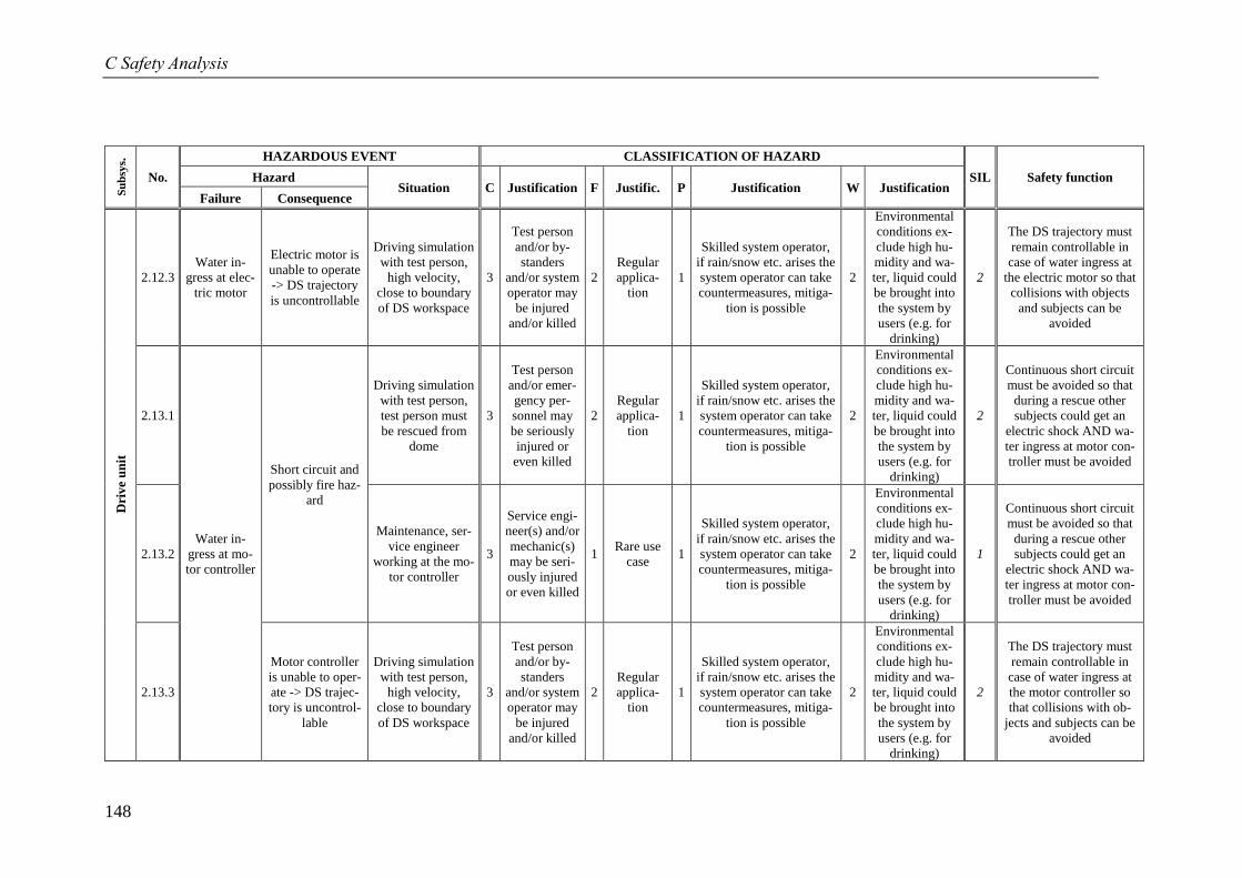
C Safety Analysis
148
Su
bsy
s.
No.
HAZARDOUS EVENT CLASSIFICATION OF HAZARD
SIL Safety function Hazard Situation C Justification F Justific. P Justification W Justification
Failure Consequence
Dri
ve
un
it
2.12.3
Water in-
gress at elec-
tric motor
Electric motor is
unable to operate
-> DS trajectory
is uncontrollable
Driving simulation
with test person,
high velocity,
close to boundary
of DS workspace
3
Test person
and/or by-
standers
and/or system
operator may
be injured
and/or killed
2
Regular
applica-
tion
1
Skilled system operator,
if rain/snow etc. arises the
system operator can take
countermeasures, mitiga-
tion is possible
2
Environmental
conditions ex-
clude high hu-
midity and wa-
ter, liquid could
be brought into
the system by
users (e.g. for
drinking)
2
The DS trajectory must
remain controllable in
case of water ingress at
the electric motor so that
collisions with objects
and subjects can be
avoided
2.13.1
Water in-
gress at mo-
tor controller
Short circuit and
possibly fire haz-
ard
Driving simulation
with test person,
test person must
be rescued from
dome
3
Test person
and/or emer-
gency per-
sonnel may
be seriously
injured or
even killed
2
Regular
applica-
tion
1
Skilled system operator,
if rain/snow etc. arises the
system operator can take
countermeasures, mitiga-
tion is possible
2
Environmental
conditions ex-
clude high hu-
midity and wa-
ter, liquid could
be brought into
the system by
users (e.g. for
drinking)
2
Continuous short circuit
must be avoided so that
during a rescue other
subjects could get an
electric shock AND wa-
ter ingress at motor con-
troller must be avoided
2.13.2
Maintenance, ser-
vice engineer
working at the mo-
tor controller
3
Service engi-
neer(s) and/or
mechanic(s)
may be seri-
ously injured
or even killed
1 Rare use
case 1
Skilled system operator,
if rain/snow etc. arises the
system operator can take
countermeasures, mitiga-
tion is possible
2
Environmental
conditions ex-
clude high hu-
midity and wa-
ter, liquid could
be brought into
the system by
users (e.g. for
drinking)
1
Continuous short circuit
must be avoided so that
during a rescue other
subjects could get an
electric shock AND wa-
ter ingress at motor con-
troller must be avoided
2.13.3
Motor controller
is unable to oper-
ate -> DS trajec-
tory is uncontrol-
lable
Driving simulation
with test person,
high velocity,
close to boundary
of DS workspace
3
Test person
and/or by-
standers
and/or system
operator may
be injured
and/or killed
2
Regular
applica-
tion
1
Skilled system operator,
if rain/snow etc. arises the
system operator can take
countermeasures, mitiga-
tion is possible
2
Environmental
conditions ex-
clude high hu-
midity and wa-
ter, liquid could
be brought into
the system by
users (e.g. for
drinking)
2
The DS trajectory must
remain controllable in
case of water ingress at
the motor controller so
that collisions with ob-
jects and subjects can be
avoided
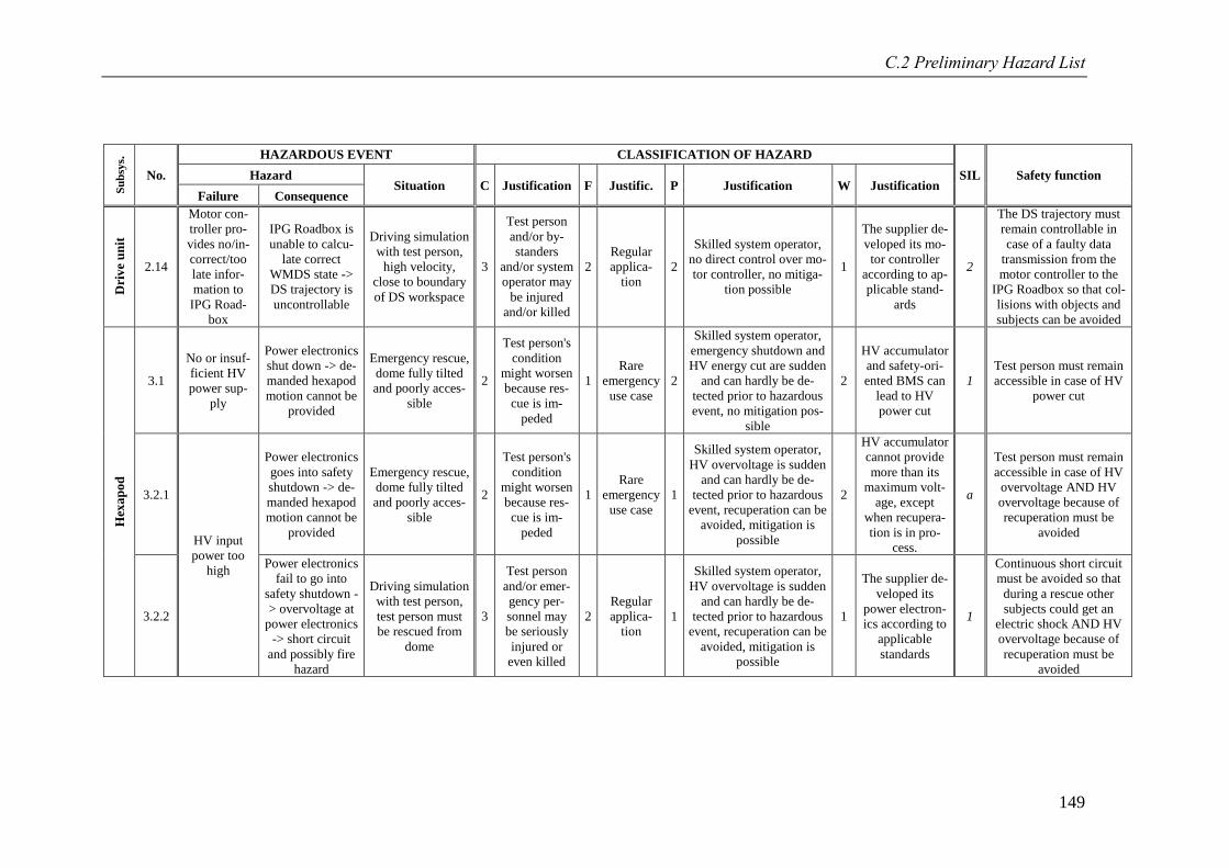
C.2 Preliminary Hazard List
149
Su
bsy
s.
No.
HAZARDOUS EVENT CLASSIFICATION OF HAZARD
SIL Safety function Hazard Situation C Justification F Justific. P Justification W Justification
Failure Consequence
Dri
ve
un
it
2.14
Motor con-
troller pro-
vides no/in-
correct/too
late infor-
mation to
IPG Road-
box
IPG Roadbox is
unable to calcu-
late correct
WMDS state ->
DS trajectory is
uncontrollable
Driving simulation
with test person,
high velocity,
close to boundary
of DS workspace
3
Test person
and/or by-
standers
and/or system
operator may
be injured
and/or killed
2
Regular
applica-
tion
2
Skilled system operator,
no direct control over mo-
tor controller, no mitiga-
tion possible
1
The supplier de-
veloped its mo-
tor controller
according to ap-
plicable stand-
ards
2
The DS trajectory must
remain controllable in
case of a faulty data
transmission from the
motor controller to the
IPG Roadbox so that col-
lisions with objects and
subjects can be avoided
Hex
ap
od
3.1
No or insuf-
ficient HV
power sup-
ply
Power electronics
shut down -> de-
manded hexapod
motion cannot be
provided
Emergency rescue,
dome fully tilted
and poorly acces-
sible
2
Test person's
condition
might worsen
because res-
cue is im-
peded
1
Rare
emergency
use case
2
Skilled system operator,
emergency shutdown and
HV energy cut are sudden
and can hardly be de-
tected prior to hazardous
event, no mitigation pos-
sible
2
HV accumulator
and safety-ori-
ented BMS can
lead to HV
power cut
1
Test person must remain
accessible in case of HV
power cut
3.2.1
HV input
power too
high
Power electronics
goes into safety
shutdown -> de-
manded hexapod
motion cannot be
provided
Emergency rescue,
dome fully tilted
and poorly acces-
sible
2
Test person's
condition
might worsen
because res-
cue is im-
peded
1
Rare
emergency
use case
1
Skilled system operator,
HV overvoltage is sudden
and can hardly be de-
tected prior to hazardous
event, recuperation can be
avoided, mitigation is
possible
2
HV accumulator
cannot provide
more than its
maximum volt-
age, except
when recupera-
tion is in pro-
cess.
a
Test person must remain
accessible in case of HV
overvoltage AND HV
overvoltage because of
recuperation must be
avoided
3.2.2
Power electronics
fail to go into
safety shutdown -
> overvoltage at
power electronics
-> short circuit
and possibly fire
hazard
Driving simulation
with test person,
test person must
be rescued from
dome
3
Test person
and/or emer-
gency per-
sonnel may
be seriously
injured or
even killed
2
Regular
applica-
tion
1
Skilled system operator,
HV overvoltage is sudden
and can hardly be de-
tected prior to hazardous
event, recuperation can be
avoided, mitigation is
possible
1
The supplier de-
veloped its
power electron-
ics according to
applicable
standards
1
Continuous short circuit
must be avoided so that
during a rescue other
subjects could get an
electric shock AND HV
overvoltage because of
recuperation must be
avoided
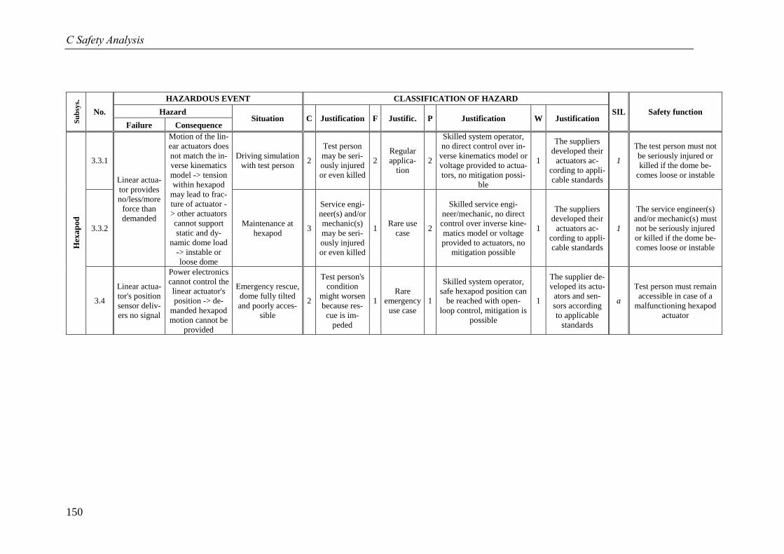
C Safety Analysis
150
Su
bsy
s.
No.
HAZARDOUS EVENT CLASSIFICATION OF HAZARD
SIL Safety function Hazard Situation C Justification F Justific. P Justification W Justification
Failure Consequence
Hex
ap
od
3.3.1
Linear actua-
tor provides
no/less/more
force than
demanded
Motion of the lin-
ear actuators does
not match the in-
verse kinematics
model -> tension
within hexapod
may lead to frac-
ture of actuator -
> other actuators
cannot support
static and dy-
namic dome load
-> instable or
loose dome
Driving simulation
with test person 2
Test person
may be seri-
ously injured
or even killed
2
Regular
applica-
tion
2
Skilled system operator,
no direct control over in-
verse kinematics model or
voltage provided to actua-
tors, no mitigation possi-
ble
1
The suppliers
developed their
actuators ac-
cording to appli-
cable standards
1
The test person must not
be seriously injured or
killed if the dome be-
comes loose or instable
3.3.2 Maintenance at
hexapod 3
Service engi-
neer(s) and/or
mechanic(s)
may be seri-
ously injured
or even killed
1 Rare use
case 2
Skilled service engi-
neer/mechanic, no direct
control over inverse kine-
matics model or voltage
provided to actuators, no
mitigation possible
1
The suppliers
developed their
actuators ac-
cording to appli-
cable standards
1
The service engineer(s)
and/or mechanic(s) must
not be seriously injured
or killed if the dome be-
comes loose or instable
3.4
Linear actua-
tor's position
sensor deliv-
ers no signal
Power electronics
cannot control the
linear actuator's
position -> de-
manded hexapod
motion cannot be
provided
Emergency rescue,
dome fully tilted
and poorly acces-
sible
2
Test person's
condition
might worsen
because res-
cue is im-
peded
1
Rare
emergency
use case
1
Skilled system operator,
safe hexapod position can
be reached with open-
loop control, mitigation is
possible
1
The supplier de-
veloped its actu-
ators and sen-
sors according
to applicable
standards
a
Test person must remain
accessible in case of a
malfunctioning hexapod
actuator
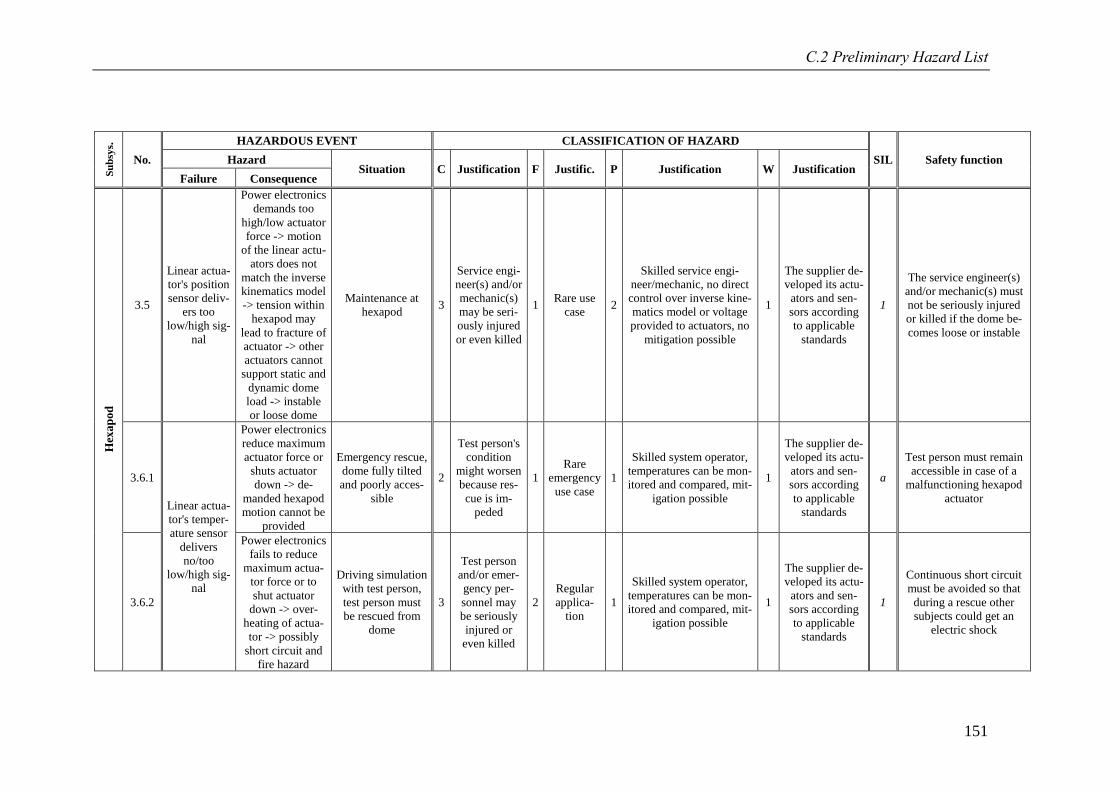
C.2 Preliminary Hazard List
151
Su
bsy
s.
No.
HAZARDOUS EVENT CLASSIFICATION OF HAZARD
SIL Safety function Hazard Situation C Justification F Justific. P Justification W Justification
Failure Consequence
Hex
ap
od
3.5
Linear actua-
tor's position
sensor deliv-
ers too
low/high sig-
nal
Power electronics
demands too
high/low actuator
force -> motion
of the linear actu-
ators does not
match the inverse
kinematics model
-> tension within
hexapod may
lead to fracture of
actuator -> other
actuators cannot
support static and
dynamic dome
load -> instable
or loose dome
Maintenance at
hexapod 3
Service engi-
neer(s) and/or
mechanic(s)
may be seri-
ously injured
or even killed
1 Rare use
case 2
Skilled service engi-
neer/mechanic, no direct
control over inverse kine-
matics model or voltage
provided to actuators, no
mitigation possible
1
The supplier de-
veloped its actu-
ators and sen-
sors according
to applicable
standards
1
The service engineer(s)
and/or mechanic(s) must
not be seriously injured
or killed if the dome be-
comes loose or instable
3.6.1
Linear actua-
tor's temper-
ature sensor
delivers
no/too
low/high sig-
nal
Power electronics
reduce maximum
actuator force or
shuts actuator
down -> de-
manded hexapod
motion cannot be
provided
Emergency rescue,
dome fully tilted
and poorly acces-
sible
2
Test person's
condition
might worsen
because res-
cue is im-
peded
1
Rare
emergency
use case
1
Skilled system operator,
temperatures can be mon-
itored and compared, mit-
igation possible
1
The supplier de-
veloped its actu-
ators and sen-
sors according
to applicable
standards
a
Test person must remain
accessible in case of a
malfunctioning hexapod
actuator
3.6.2
Power electronics
fails to reduce
maximum actua-
tor force or to
shut actuator
down -> over-
heating of actua-
tor -> possibly
short circuit and
fire hazard
Driving simulation
with test person,
test person must
be rescued from
dome
3
Test person
and/or emer-
gency per-
sonnel may
be seriously
injured or
even killed
2
Regular
applica-
tion
1
Skilled system operator,
temperatures can be mon-
itored and compared, mit-
igation possible
1
The supplier de-
veloped its actu-
ators and sen-
sors according
to applicable
standards
1
Continuous short circuit
must be avoided so that
during a rescue other
subjects could get an
electric shock
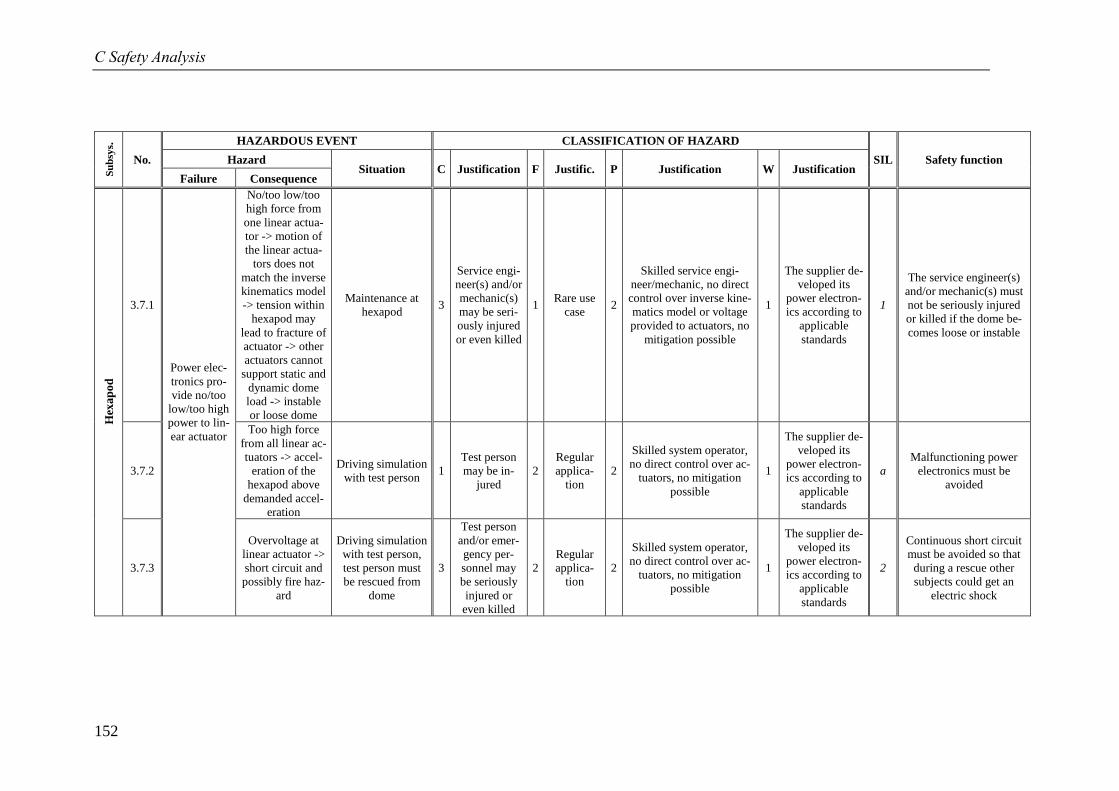
C Safety Analysis
152
Su
bsy
s.
No.
HAZARDOUS EVENT CLASSIFICATION OF HAZARD
SIL Safety function Hazard Situation C Justification F Justific. P Justification W Justification
Failure Consequence
Hex
ap
od
3.7.1
Power elec-
tronics pro-
vide no/too
low/too high
power to lin-
ear actuator
No/too low/too
high force from
one linear actua-
tor -> motion of
the linear actua-
tors does not
match the inverse
kinematics model
-> tension within
hexapod may
lead to fracture of
actuator -> other
actuators cannot
support static and
dynamic dome
load -> instable
or loose dome
Maintenance at
hexapod 3
Service engi-
neer(s) and/or
mechanic(s)
may be seri-
ously injured
or even killed
1 Rare use
case 2
Skilled service engi-
neer/mechanic, no direct
control over inverse kine-
matics model or voltage
provided to actuators, no
mitigation possible
1
The supplier de-
veloped its
power electron-
ics according to
applicable
standards
1
The service engineer(s)
and/or mechanic(s) must
not be seriously injured
or killed if the dome be-
comes loose or instable
3.7.2
Too high force
from all linear ac-
tuators -> accel-
eration of the
hexapod above
demanded accel-
eration
Driving simulation
with test person 1
Test person
may be in-
jured
2
Regular
applica-
tion
2
Skilled system operator,
no direct control over ac-
tuators, no mitigation
possible
1
The supplier de-
veloped its
power electron-
ics according to
applicable
standards
a
Malfunctioning power
electronics must be
avoided
3.7.3
Overvoltage at
linear actuator ->
short circuit and
possibly fire haz-
ard
Driving simulation
with test person,
test person must
be rescued from
dome
3
Test person
and/or emer-
gency per-
sonnel may
be seriously
injured or
even killed
2
Regular
applica-
tion
2
Skilled system operator,
no direct control over ac-
tuators, no mitigation
possible
1
The supplier de-
veloped its
power electron-
ics according to
applicable
standards
2
Continuous short circuit
must be avoided so that
during a rescue other
subjects could get an
electric shock
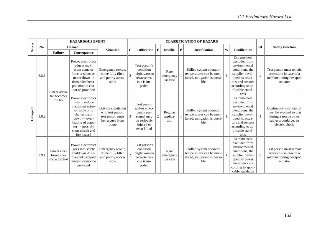
C.2 Preliminary Hazard List
153
Su
bsy
s.
No.
HAZARDOUS EVENT CLASSIFICATION OF HAZARD
SIL Safety function Hazard Situation C Justification F Justific. P Justification W Justification
Failure Consequence
Hex
ap
od
3.8.1
Linear actua-
tor becomes
too hot
Power electronics
reduces maxi-
mum actuator
force or shuts ac-
tuator down ->
demanded hexa-
pod motion can-
not be provided
Emergency rescue,
dome fully tilted
and poorly acces-
sible
2
Test person's
condition
might worsen
because res-
cue is im-
peded
1
Rare
emergency
use case
1
Skilled system operator,
temperatures can be mon-
itored, mitigation is possi-
ble
1
Extreme heat
excluded from
environmental
conditions, the
supplier devel-
oped its actua-
tors and sensors
according to ap-
plicable stand-
ards
a
Test person must remain
accessible in case of a
malfunctioning hexapod
actuator
3.8.2
Power electronics
fails to reduce
maximum actua-
tor force or to
shut actuator
down -> over-
heating of actua-
tor -> possibly
short circuit and
fire hazard
Driving simulation
with test person,
test person must
be rescued from
dome
3
Test person
and/or emer-
gency per-
sonnel may
be seriously
injured or
even killed
2
Regular
applica-
tion
1
Skilled system operator,
temperatures can be mon-
itored, mitigation is possi-
ble
1
Extreme heat
excluded from
environmental
conditions, the
supplier devel-
oped its actua-
tors and sensors
according to ap-
plicable stand-
ards
1
Continuous short circuit
must be avoided so that
during a rescue other
subjects could get an
electric shock
3.9.1
Power elec-
tronics be-
come too hot
Power electronics
goes into safety
shutdown -> de-
manded hexapod
motion cannot be
provided
Emergency rescue,
dome fully tilted
and poorly acces-
sible
2
Test person's
condition
might worsen
because res-
cue is im-
peded
1
Rare
emergency
use case
1
Skilled system operator,
temperatures can be mon-
itored, mitigation is possi-
ble
1
Extreme heat
excluded from
environmental
conditions, the
supplier devel-
oped its power
electronics ac-
cording to appli-
cable standards
a
Test person must remain
accessible in case of a
malfunctioning hexapod
actuator
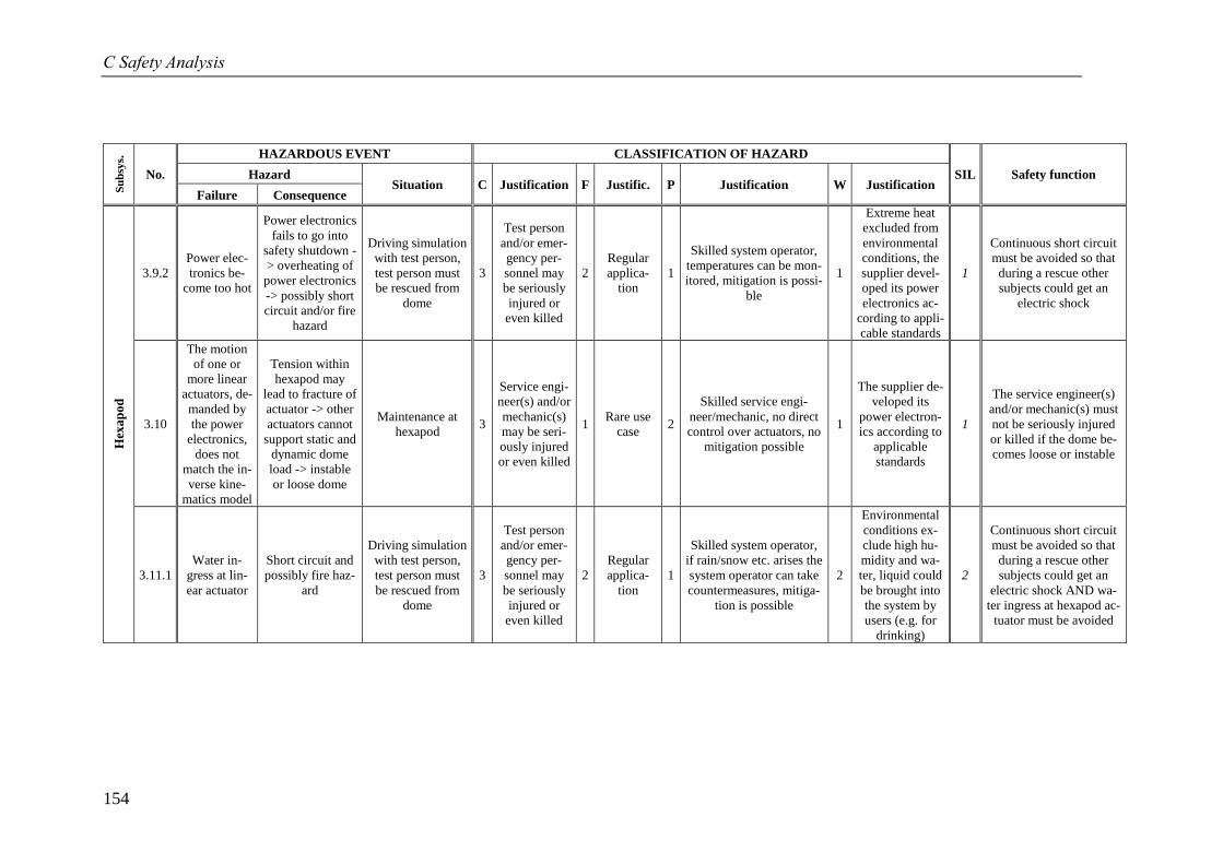
C Safety Analysis
154
Su
bsy
s.
No.
HAZARDOUS EVENT CLASSIFICATION OF HAZARD
SIL Safety function Hazard Situation C Justification F Justific. P Justification W Justification
Failure Consequence
Hex
ap
od
3.9.2
Power elec-
tronics be-
come too hot
Power electronics
fails to go into
safety shutdown -
> overheating of
power electronics
-> possibly short
circuit and/or fire
hazard
Driving simulation
with test person,
test person must
be rescued from
dome
3
Test person
and/or emer-
gency per-
sonnel may
be seriously
injured or
even killed
2
Regular
applica-
tion
1
Skilled system operator,
temperatures can be mon-
itored, mitigation is possi-
ble
1
Extreme heat
excluded from
environmental
conditions, the
supplier devel-
oped its power
electronics ac-
cording to appli-
cable standards
1
Continuous short circuit
must be avoided so that
during a rescue other
subjects could get an
electric shock
3.10
The motion
of one or
more linear
actuators, de-
manded by
the power
electronics,
does not
match the in-
verse kine-
matics model
Tension within
hexapod may
lead to fracture of
actuator -> other
actuators cannot
support static and
dynamic dome
load -> instable
or loose dome
Maintenance at
hexapod 3
Service engi-
neer(s) and/or
mechanic(s)
may be seri-
ously injured
or even killed
1 Rare use
case 2
Skilled service engi-
neer/mechanic, no direct
control over actuators, no
mitigation possible
1
The supplier de-
veloped its
power electron-
ics according to
applicable
standards
1
The service engineer(s)
and/or mechanic(s) must
not be seriously injured
or killed if the dome be-
comes loose or instable
3.11.1
Water in-
gress at lin-
ear actuator
Short circuit and
possibly fire haz-
ard
Driving simulation
with test person,
test person must
be rescued from
dome
3
Test person
and/or emer-
gency per-
sonnel may
be seriously
injured or
even killed
2
Regular
applica-
tion
1
Skilled system operator,
if rain/snow etc. arises the
system operator can take
countermeasures, mitiga-
tion is possible
2
Environmental
conditions ex-
clude high hu-
midity and wa-
ter, liquid could
be brought into
the system by
users (e.g. for
drinking)
2
Continuous short circuit
must be avoided so that
during a rescue other
subjects could get an
electric shock AND wa-
ter ingress at hexapod ac-
tuator must be avoided
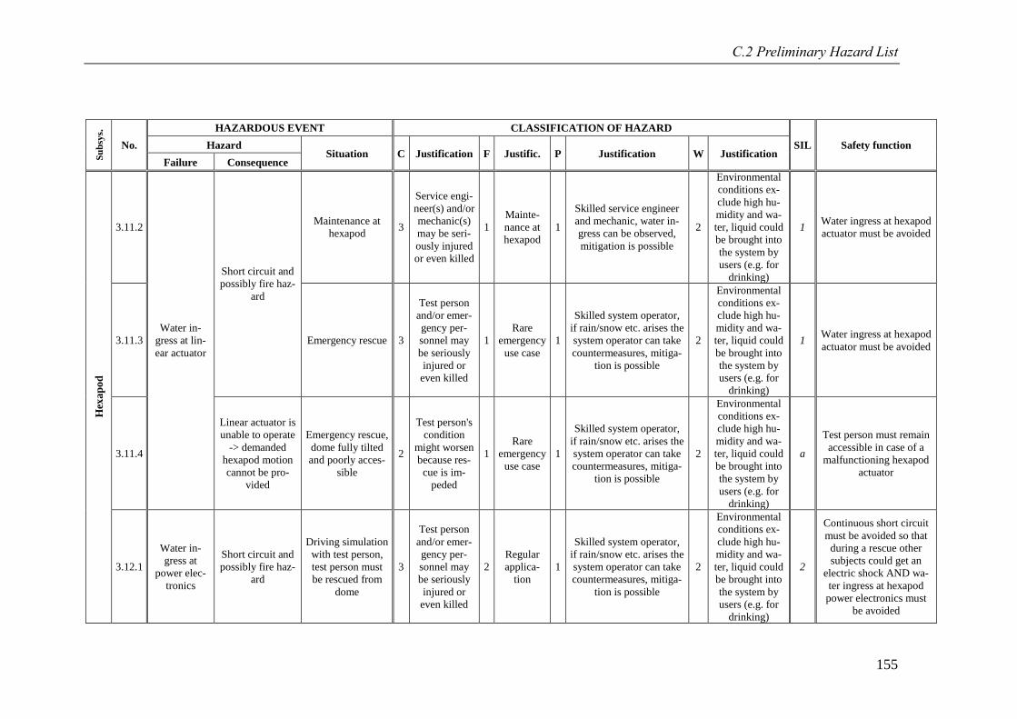
C.2 Preliminary Hazard List
155
Su
bsy
s.
No.
HAZARDOUS EVENT CLASSIFICATION OF HAZARD
SIL Safety function Hazard Situation C Justification F Justific. P Justification W Justification
Failure Consequence
Hex
ap
od
3.11.2
Water in-
gress at lin-
ear actuator
Short circuit and
possibly fire haz-
ard
Maintenance at
hexapod 3
Service engi-
neer(s) and/or
mechanic(s)
may be seri-
ously injured
or even killed
1
Mainte-
nance at
hexapod
1
Skilled service engineer
and mechanic, water in-
gress can be observed,
mitigation is possible
2
Environmental
conditions ex-
clude high hu-
midity and wa-
ter, liquid could
be brought into
the system by
users (e.g. for
drinking)
1 Water ingress at hexapod
actuator must be avoided
3.11.3 Emergency rescue 3
Test person
and/or emer-
gency per-
sonnel may
be seriously
injured or
even killed
1
Rare
emergency
use case
1
Skilled system operator,
if rain/snow etc. arises the
system operator can take
countermeasures, mitiga-
tion is possible
2
Environmental
conditions ex-
clude high hu-
midity and wa-
ter, liquid could
be brought into
the system by
users (e.g. for
drinking)
1 Water ingress at hexapod
actuator must be avoided
3.11.4
Linear actuator is
unable to operate
-> demanded
hexapod motion
cannot be pro-
vided
Emergency rescue,
dome fully tilted
and poorly acces-
sible
2
Test person's
condition
might worsen
because res-
cue is im-
peded
1
Rare
emergency
use case
1
Skilled system operator,
if rain/snow etc. arises the
system operator can take
countermeasures, mitiga-
tion is possible
2
Environmental
conditions ex-
clude high hu-
midity and wa-
ter, liquid could
be brought into
the system by
users (e.g. for
drinking)
a
Test person must remain
accessible in case of a
malfunctioning hexapod
actuator
3.12.1
Water in-
gress at
power elec-
tronics
Short circuit and
possibly fire haz-
ard
Driving simulation
with test person,
test person must
be rescued from
dome
3
Test person
and/or emer-
gency per-
sonnel may
be seriously
injured or
even killed
2
Regular
applica-
tion
1
Skilled system operator,
if rain/snow etc. arises the
system operator can take
countermeasures, mitiga-
tion is possible
2
Environmental
conditions ex-
clude high hu-
midity and wa-
ter, liquid could
be brought into
the system by
users (e.g. for
drinking)
2
Continuous short circuit
must be avoided so that
during a rescue other
subjects could get an
electric shock AND wa-
ter ingress at hexapod
power electronics must
be avoided
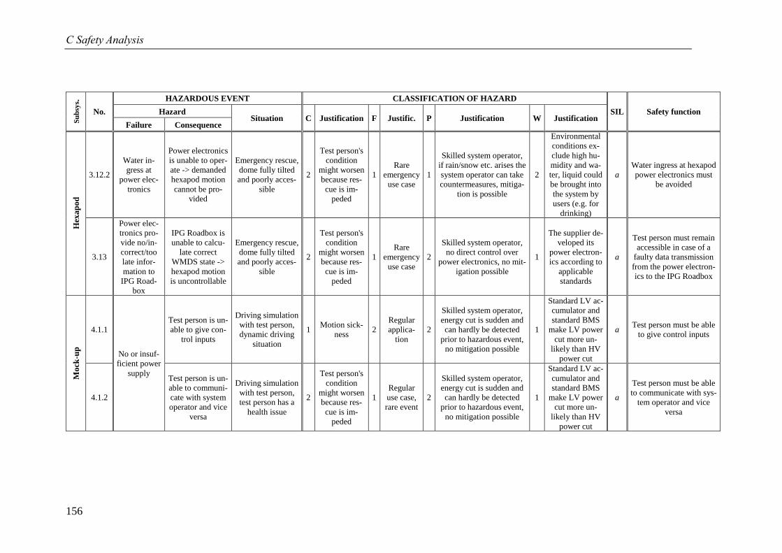
C Safety Analysis
156
Su
bsy
s.
No.
HAZARDOUS EVENT CLASSIFICATION OF HAZARD
SIL Safety function Hazard Situation C Justification F Justific. P Justification W Justification
Failure Consequence
Hex
ap
od
3.12.2
Water in-
gress at
power elec-
tronics
Power electronics
is unable to oper-
ate -> demanded
hexapod motion
cannot be pro-
vided
Emergency rescue,
dome fully tilted
and poorly acces-
sible
2
Test person's
condition
might worsen
because res-
cue is im-
peded
1
Rare
emergency
use case
1
Skilled system operator,
if rain/snow etc. arises the
system operator can take
countermeasures, mitiga-
tion is possible
2
Environmental
conditions ex-
clude high hu-
midity and wa-
ter, liquid could
be brought into
the system by
users (e.g. for
drinking)
a
Water ingress at hexapod
power electronics must
be avoided
3.13
Power elec-
tronics pro-
vide no/in-
correct/too
late infor-
mation to
IPG Road-
box
IPG Roadbox is
unable to calcu-
late correct
WMDS state ->
hexapod motion
is uncontrollable
Emergency rescue,
dome fully tilted
and poorly acces-
sible
2
Test person's
condition
might worsen
because res-
cue is im-
peded
1
Rare
emergency
use case
2
Skilled system operator,
no direct control over
power electronics, no mit-
igation possible
1
The supplier de-
veloped its
power electron-
ics according to
applicable
standards
a
Test person must remain
accessible in case of a
faulty data transmission
from the power electron-
ics to the IPG Roadbox
Mo
ck-u
p
4.1.1
No or insuf-
ficient power
supply
Test person is un-
able to give con-
trol inputs
Driving simulation
with test person,
dynamic driving
situation
1 Motion sick-
ness 2
Regular
applica-
tion
2
Skilled system operator,
energy cut is sudden and
can hardly be detected
prior to hazardous event,
no mitigation possible
1
Standard LV ac-
cumulator and
standard BMS
make LV power
cut more un-
likely than HV
power cut
a Test person must be able
to give control inputs
4.1.2
Test person is un-
able to communi-
cate with system
operator and vice
versa
Driving simulation
with test person,
test person has a
health issue
2
Test person's
condition
might worsen
because res-
cue is im-
peded
1
Regular
use case,
rare event
2
Skilled system operator,
energy cut is sudden and
can hardly be detected
prior to hazardous event,
no mitigation possible
1
Standard LV ac-
cumulator and
standard BMS
make LV power
cut more un-
likely than HV
power cut
a
Test person must be able
to communicate with sys-
tem operator and vice
versa
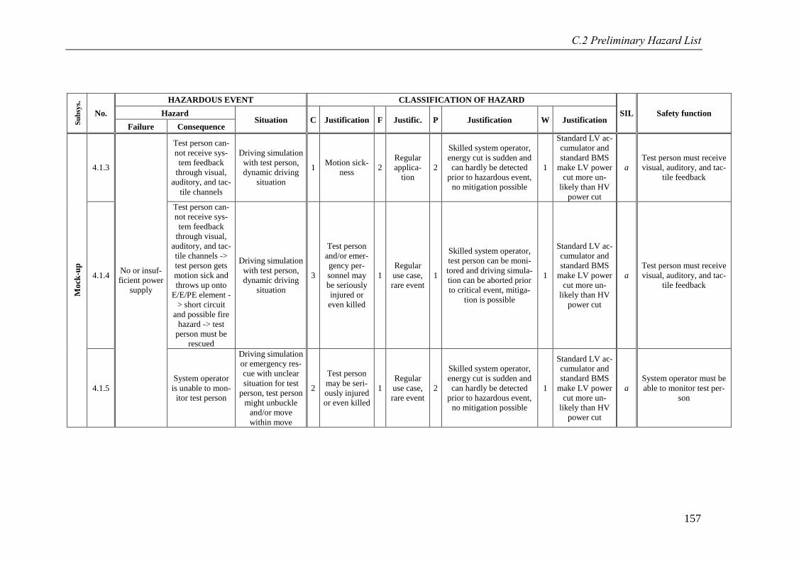
C.2 Preliminary Hazard List
157
Su
bsy
s.
No.
HAZARDOUS EVENT CLASSIFICATION OF HAZARD
SIL Safety function Hazard Situation C Justification F Justific. P Justification W Justification
Failure Consequence
Mo
ck-u
p
4.1.3
No or insuf-
ficient power
supply
Test person can-
not receive sys-
tem feedback
through visual,
auditory, and tac-
tile channels
Driving simulation
with test person,
dynamic driving
situation
1 Motion sick-
ness 2
Regular
applica-
tion
2
Skilled system operator,
energy cut is sudden and
can hardly be detected
prior to hazardous event,
no mitigation possible
1
Standard LV ac-
cumulator and
standard BMS
make LV power
cut more un-
likely than HV
power cut
a
Test person must receive
visual, auditory, and tac-
tile feedback
4.1.4
Test person can-
not receive sys-
tem feedback
through visual,
auditory, and tac-
tile channels ->
test person gets
motion sick and
throws up onto
E/E/PE element -
> short circuit
and possible fire
hazard -> test
person must be
rescued
Driving simulation
with test person,
dynamic driving
situation
3
Test person
and/or emer-
gency per-
sonnel may
be seriously
injured or
even killed
1
Regular
use case,
rare event
1
Skilled system operator,
test person can be moni-
tored and driving simula-
tion can be aborted prior
to critical event, mitiga-
tion is possible
1
Standard LV ac-
cumulator and
standard BMS
make LV power
cut more un-
likely than HV
power cut
a
Test person must receive
visual, auditory, and tac-
tile feedback
4.1.5
System operator
is unable to mon-
itor test person
Driving simulation
or emergency res-
cue with unclear
situation for test
person, test person
might unbuckle
and/or move
within move
2
Test person
may be seri-
ously injured
or even killed
1
Regular
use case,
rare event
2
Skilled system operator,
energy cut is sudden and
can hardly be detected
prior to hazardous event,
no mitigation possible
1
Standard LV ac-
cumulator and
standard BMS
make LV power
cut more un-
likely than HV
power cut
a
System operator must be
able to monitor test per-
son
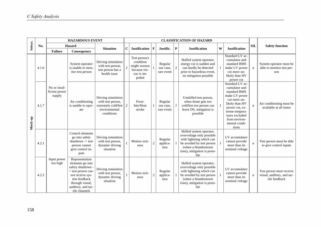
C Safety Analysis
158
Su
bsy
s.
No.
HAZARDOUS EVENT CLASSIFICATION OF HAZARD
SIL Safety function Hazard Situation C Justification F Justific. P Justification W Justification
Failure Consequence
Mo
ck-u
p
4.1.6
No or insuf-
ficient power
supply
System operator
is unable to mon-
itor test person
Driving simulation
with test person,
test person has a
health issue
2
Test person's
condition
might worsen
because res-
cue is im-
peded
1
Regular
use case,
rare event
2
Skilled system operator,
energy cut is sudden and
can hardly be detected
prior to hazardous event,
no mitigation possible
1
Standard LV ac-
cumulator and
standard BMS
make LV power
cut more un-
likely than HV
power cut
a
System operator must be
able to monitor test per-
son
4.1.7
Air conditioning
is unable to oper-
ate
Driving simulation
with test person,
extremely cold/hot
environmental
conditions
2
Frost-
bite/Heat
stroke
1
Regular
use case,
rare event
1
Unskilled test person,
when dome gets too
cold/hot test person can
leave DS, mitigation is
possible
1
Standard LV ac-
cumulator and
standard BMS
make LV power
cut more un-
likely than HV
power cut, ex-
treme tempera-
tures excluded
from environ-
mental condi-
tions
a Air conditioning must be
available at all times
4.2.1
Input power
too high
Control elements
go into safety
shutdown -> test
person cannot
give control in-
puts
Driving simulation
with test person,
dynamic driving
situation
1 Motion sick-
ness 2
Regular
applica-
tion
1
Skilled system operator,
overvoltage only possible
with lightning which can
be avoided by test person
(when a thunderstorm
rises), mitigation is possi-
ble
1
LV accumulator
cannot provide
more than its
nominal voltage
a Test person must be able
to give control inputs
4.2.2
Representation
elements go into
safety shutdown -
> test person can-
not receive sys-
tem feedback
through visual,
auditory, and tac-
tile channels
Driving simulation
with test person,
dynamic driving
situation
1 Motion sick-
ness 2
Regular
applica-
tion
1
Skilled system operator,
overvoltage only possible
with lightning which can
be avoided by test person
(when a thunderstorm
rises), mitigation is possi-
ble
1
LV accumulator
cannot provide
more than its
nominal voltage
a
Test person must receive
visual, auditory, and tac-
tile feedback
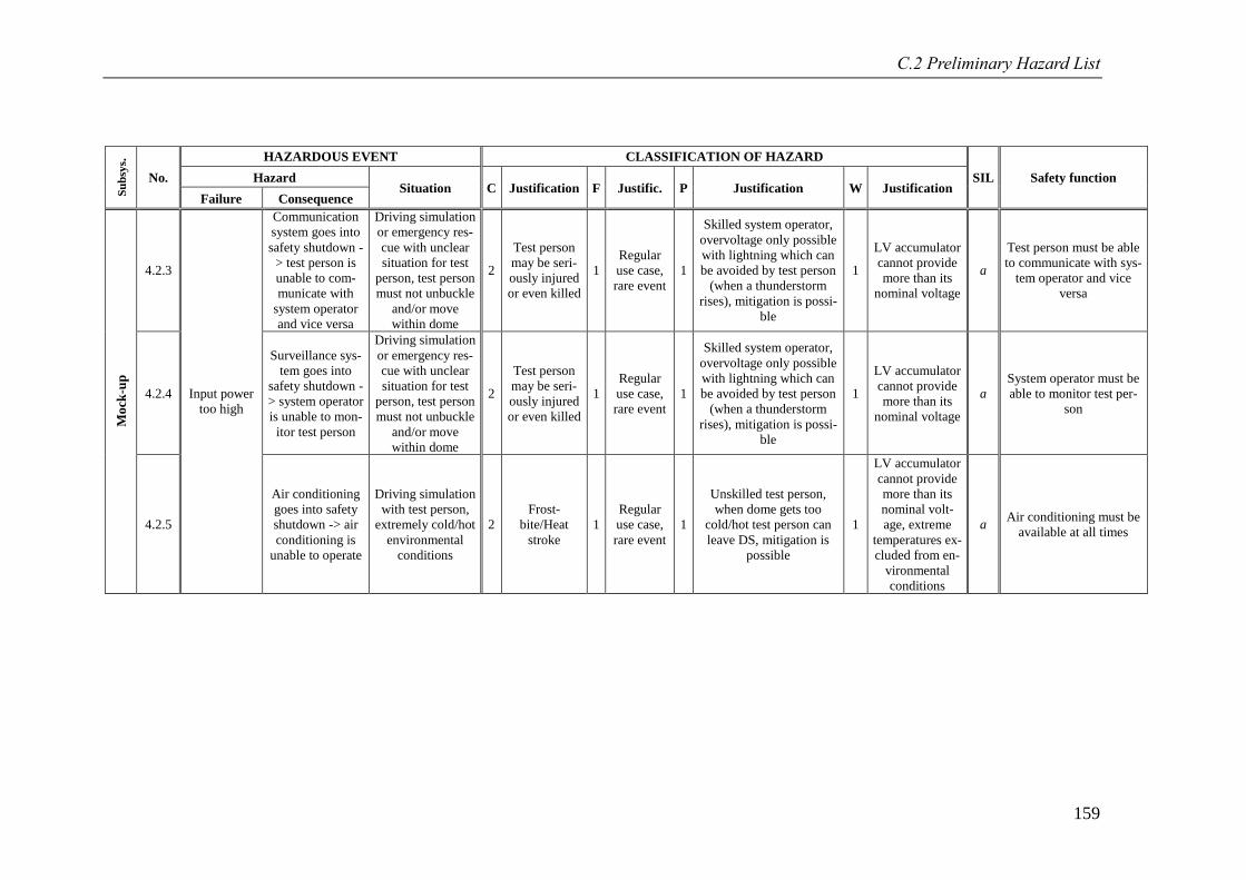
C.2 Preliminary Hazard List
159
Su
bsy
s.
No.
HAZARDOUS EVENT CLASSIFICATION OF HAZARD
SIL Safety function Hazard Situation C Justification F Justific. P Justification W Justification
Failure Consequence
Mo
ck-u
p
4.2.3
Input power
too high
Communication
system goes into
safety shutdown -
> test person is
unable to com-
municate with
system operator
and vice versa
Driving simulation
or emergency res-
cue with unclear
situation for test
person, test person
must not unbuckle
and/or move
within dome
2
Test person
may be seri-
ously injured
or even killed
1
Regular
use case,
rare event
1
Skilled system operator,
overvoltage only possible
with lightning which can
be avoided by test person
(when a thunderstorm
rises), mitigation is possi-
ble
1
LV accumulator
cannot provide
more than its
nominal voltage
a
Test person must be able
to communicate with sys-
tem operator and vice
versa
4.2.4
Surveillance sys-
tem goes into
safety shutdown -
> system operator
is unable to mon-
itor test person
Driving simulation
or emergency res-
cue with unclear
situation for test
person, test person
must not unbuckle
and/or move
within dome
2
Test person
may be seri-
ously injured
or even killed
1
Regular
use case,
rare event
1
Skilled system operator,
overvoltage only possible
with lightning which can
be avoided by test person
(when a thunderstorm
rises), mitigation is possi-
ble
1
LV accumulator
cannot provide
more than its
nominal voltage
a
System operator must be
able to monitor test per-
son
4.2.5
Air conditioning
goes into safety
shutdown -> air
conditioning is
unable to operate
Driving simulation
with test person,
extremely cold/hot
environmental
conditions
2
Frost-
bite/Heat
stroke
1
Regular
use case,
rare event
1
Unskilled test person,
when dome gets too
cold/hot test person can
leave DS, mitigation is
possible
1
LV accumulator
cannot provide
more than its
nominal volt-
age, extreme
temperatures ex-
cluded from en-
vironmental
conditions
a Air conditioning must be
available at all times
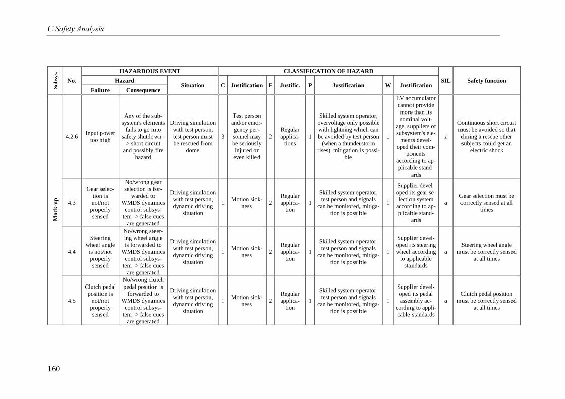
C Safety Analysis
160
Su
bsy
s.
No.
HAZARDOUS EVENT CLASSIFICATION OF HAZARD
SIL Safety function Hazard Situation C Justification F Justific. P Justification W Justification
Failure Consequence
Mo
ck-u
p
4.2.6 Input power
too high
Any of the sub-
system's elements
fails to go into
safety shutdown -
> short circuit
and possibly fire
hazard
Driving simulation
with test person,
test person must
be rescued from
dome
3
Test person
and/or emer-
gency per-
sonnel may
be seriously
injured or
even killed
2
Regular
applica-
tions
1
Skilled system operator,
overvoltage only possible
with lightning which can
be avoided by test person
(when a thunderstorm
rises), mitigation is possi-
ble
1
LV accumulator
cannot provide
more than its
nominal volt-
age, suppliers of
subsystem's ele-
ments devel-
oped their com-
ponents
according to ap-
plicable stand-
ards
1
Continuous short circuit
must be avoided so that
during a rescue other
subjects could get an
electric shock
4.3
Gear selec-
tion is
not/not
properly
sensed
No/wrong gear
selection is for-
warded to
WMDS dynamics
control subsys-
tem -> false cues
are generated
Driving simulation
with test person,
dynamic driving
situation
1 Motion sick-
ness 2
Regular
applica-
tion
1
Skilled system operator,
test person and signals
can be monitored, mitiga-
tion is possible
1
Supplier devel-
oped its gear se-
lection system
according to ap-
plicable stand-
ards
a
Gear selection must be
correctly sensed at all
times
4.4
Steering
wheel angle
is not/not
properly
sensed
No/wrong steer-
ing wheel angle
is forwarded to
WMDS dynamics
control subsys-
tem -> false cues
are generated
Driving simulation
with test person,
dynamic driving
situation
1 Motion sick-
ness 2
Regular
applica-
tion
1
Skilled system operator,
test person and signals
can be monitored, mitiga-
tion is possible
1
Supplier devel-
oped its steering
wheel according
to applicable
standards
a
Steering wheel angle
must be correctly sensed
at all times
4.5
Clutch pedal
position is
not/not
properly
sensed
No/wrong clutch
pedal position is
forwarded to
WMDS dynamics
control subsys-
tem -> false cues
are generated
Driving simulation
with test person,
dynamic driving
situation
1 Motion sick-
ness 2
Regular
applica-
tion
1
Skilled system operator,
test person and signals
can be monitored, mitiga-
tion is possible
1
Supplier devel-
oped its pedal
assembly ac-
cording to appli-
cable standards
a
Clutch pedal position
must be correctly sensed
at all times
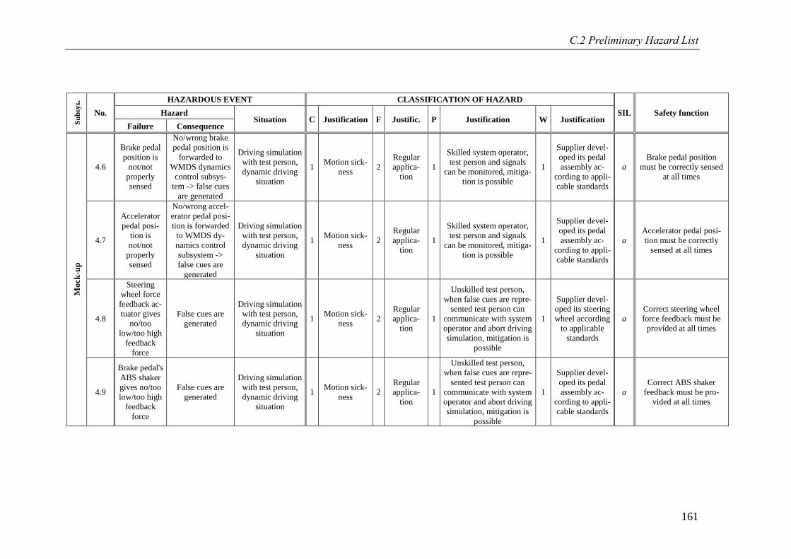
C.2 Preliminary Hazard List
161
Su
bsy
s.
No.
HAZARDOUS EVENT CLASSIFICATION OF HAZARD
SIL Safety function Hazard Situation C Justification F Justific. P Justification W Justification
Failure Consequence
Mo
ck-u
p
4.6
Brake pedal
position is
not/not
properly
sensed
No/wrong brake
pedal position is
forwarded to
WMDS dynamics
control subsys-
tem -> false cues
are generated
Driving simulation
with test person,
dynamic driving
situation
1 Motion sick-
ness 2
Regular
applica-
tion
1
Skilled system operator,
test person and signals
can be monitored, mitiga-
tion is possible
1
Supplier devel-
oped its pedal
assembly ac-
cording to appli-
cable standards
a
Brake pedal position
must be correctly sensed
at all times
4.7
Accelerator
pedal posi-
tion is
not/not
properly
sensed
No/wrong accel-
erator pedal posi-
tion is forwarded
to WMDS dy-
namics control
subsystem ->
false cues are
generated
Driving simulation
with test person,
dynamic driving
situation
1 Motion sick-
ness 2
Regular
applica-
tion
1
Skilled system operator,
test person and signals
can be monitored, mitiga-
tion is possible
1
Supplier devel-
oped its pedal
assembly ac-
cording to appli-
cable standards
a
Accelerator pedal posi-
tion must be correctly
sensed at all times
4.8
Steering
wheel force
feedback ac-
tuator gives
no/too
low/too high
feedback
force
False cues are
generated
Driving simulation
with test person,
dynamic driving
situation
1 Motion sick-
ness 2
Regular
applica-
tion
1
Unskilled test person,
when false cues are repre-
sented test person can
communicate with system
operator and abort driving
simulation, mitigation is
possible
1
Supplier devel-
oped its steering
wheel according
to applicable
standards
a
Correct steering wheel
force feedback must be
provided at all times
4.9
Brake pedal's
ABS shaker
gives no/too
low/too high
feedback
force
False cues are
generated
Driving simulation
with test person,
dynamic driving
situation
1 Motion sick-
ness 2
Regular
applica-
tion
1
Unskilled test person,
when false cues are repre-
sented test person can
communicate with system
operator and abort driving
simulation, mitigation is
possible
1
Supplier devel-
oped its pedal
assembly ac-
cording to appli-
cable standards
a
Correct ABS shaker
feedback must be pro-
vided at all times
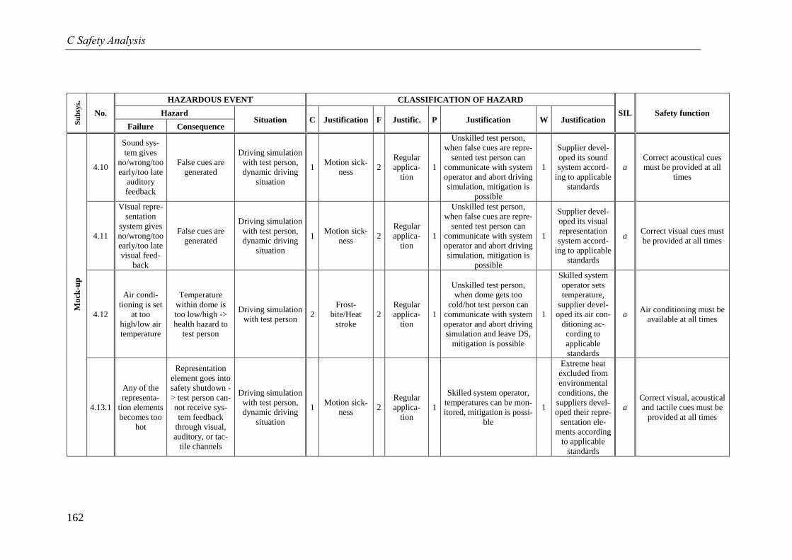
C Safety Analysis
162
Su
bsy
s.
No.
HAZARDOUS EVENT CLASSIFICATION OF HAZARD
SIL Safety function Hazard Situation C Justification F Justific. P Justification W Justification
Failure Consequence
Mo
ck-u
p
4.10
Sound sys-
tem gives
no/wrong/too
early/too late
auditory
feedback
False cues are
generated
Driving simulation
with test person,
dynamic driving
situation
1 Motion sick-
ness 2
Regular
applica-
tion
1
Unskilled test person,
when false cues are repre-
sented test person can
communicate with system
operator and abort driving
simulation, mitigation is
possible
1
Supplier devel-
oped its sound
system accord-
ing to applicable
standards
a
Correct acoustical cues
must be provided at all
times
4.11
Visual repre-
sentation
system gives
no/wrong/too
early/too late
visual feed-
back
False cues are
generated
Driving simulation
with test person,
dynamic driving
situation
1 Motion sick-
ness 2
Regular
applica-
tion
1
Unskilled test person,
when false cues are repre-
sented test person can
communicate with system
operator and abort driving
simulation, mitigation is
possible
1
Supplier devel-
oped its visual
representation
system accord-
ing to applicable
standards
a Correct visual cues must
be provided at all times
4.12
Air condi-
tioning is set
at too
high/low air
temperature
Temperature
within dome is
too low/high ->
health hazard to
test person
Driving simulation
with test person 2
Frost-
bite/Heat
stroke
2
Regular
applica-
tion
1
Unskilled test person,
when dome gets too
cold/hot test person can
communicate with system
operator and abort driving
simulation and leave DS,
mitigation is possible
1
Skilled system
operator sets
temperature,
supplier devel-
oped its air con-
ditioning ac-
cording to
applicable
standards
a Air conditioning must be
available at all times
4.13.1
Any of the
representa-
tion elements
becomes too
hot
Representation
element goes into
safety shutdown -
> test person can-
not receive sys-
tem feedback
through visual,
auditory, or tac-
tile channels
Driving simulation
with test person,
dynamic driving
situation
1 Motion sick-
ness 2
Regular
applica-
tion
1
Skilled system operator,
temperatures can be mon-
itored, mitigation is possi-
ble
1
Extreme heat
excluded from
environmental
conditions, the
suppliers devel-
oped their repre-
sentation ele-
ments according
to applicable
standards
a
Correct visual, acoustical
and tactile cues must be
provided at all times
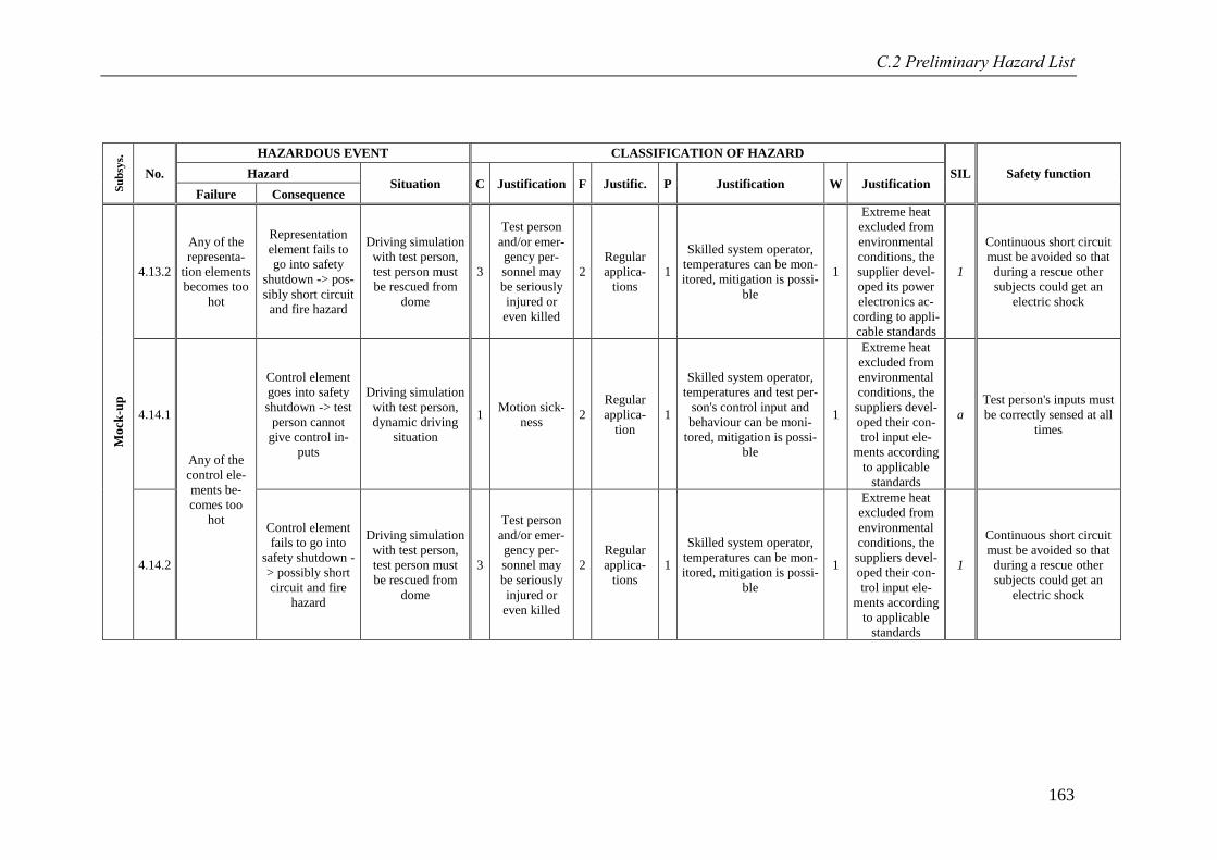
C.2 Preliminary Hazard List
163
Su
bsy
s.
No.
HAZARDOUS EVENT CLASSIFICATION OF HAZARD
SIL Safety function Hazard Situation C Justification F Justific. P Justification W Justification
Failure Consequence
Mo
ck-u
p
4.13.2
Any of the
representa-
tion elements
becomes too
hot
Representation
element fails to
go into safety
shutdown -> pos-
sibly short circuit
and fire hazard
Driving simulation
with test person,
test person must
be rescued from
dome
3
Test person
and/or emer-
gency per-
sonnel may
be seriously
injured or
even killed
2
Regular
applica-
tions
1
Skilled system operator,
temperatures can be mon-
itored, mitigation is possi-
ble
1
Extreme heat
excluded from
environmental
conditions, the
supplier devel-
oped its power
electronics ac-
cording to appli-
cable standards
1
Continuous short circuit
must be avoided so that
during a rescue other
subjects could get an
electric shock
4.14.1
Any of the
control ele-
ments be-
comes too
hot
Control element
goes into safety
shutdown -> test
person cannot
give control in-
puts
Driving simulation
with test person,
dynamic driving
situation
1 Motion sick-
ness 2
Regular
applica-
tion
1
Skilled system operator,
temperatures and test per-
son's control input and
behaviour can be moni-
tored, mitigation is possi-
ble
1
Extreme heat
excluded from
environmental
conditions, the
suppliers devel-
oped their con-
trol input ele-
ments according
to applicable
standards
a
Test person's inputs must
be correctly sensed at all
times
4.14.2
Control element
fails to go into
safety shutdown -
> possibly short
circuit and fire
hazard
Driving simulation
with test person,
test person must
be rescued from
dome
3
Test person
and/or emer-
gency per-
sonnel may
be seriously
injured or
even killed
2
Regular
applica-
tions
1
Skilled system operator,
temperatures can be mon-
itored, mitigation is possi-
ble
1
Extreme heat
excluded from
environmental
conditions, the
suppliers devel-
oped their con-
trol input ele-
ments according
to applicable
standards
1
Continuous short circuit
must be avoided so that
during a rescue other
subjects could get an
electric shock
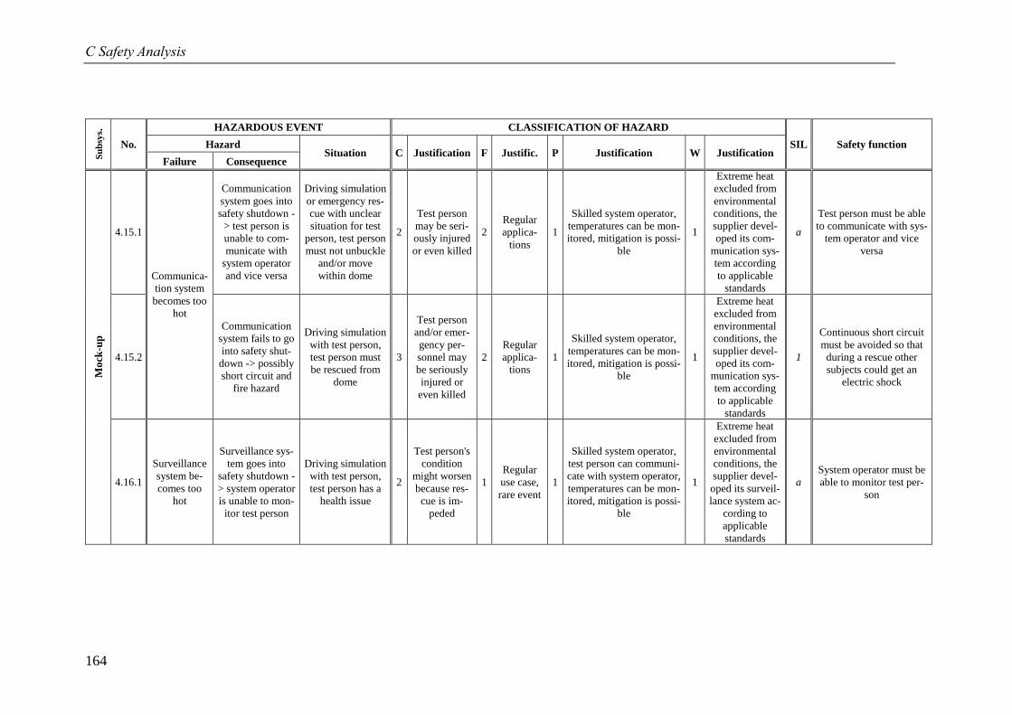
C Safety Analysis
164
Su
bsy
s.
No.
HAZARDOUS EVENT CLASSIFICATION OF HAZARD
SIL Safety function Hazard Situation C Justification F Justific. P Justification W Justification
Failure Consequence
Mo
ck-u
p
4.15.1
Communica-
tion system
becomes too
hot
Communication
system goes into
safety shutdown -
> test person is
unable to com-
municate with
system operator
and vice versa
Driving simulation
or emergency res-
cue with unclear
situation for test
person, test person
must not unbuckle
and/or move
within dome
2
Test person
may be seri-
ously injured
or even killed
2
Regular
applica-
tions
1
Skilled system operator,
temperatures can be mon-
itored, mitigation is possi-
ble
1
Extreme heat
excluded from
environmental
conditions, the
supplier devel-
oped its com-
munication sys-
tem according
to applicable
standards
a
Test person must be able
to communicate with sys-
tem operator and vice
versa
4.15.2
Communication
system fails to go
into safety shut-
down -> possibly
short circuit and
fire hazard
Driving simulation
with test person,
test person must
be rescued from
dome
3
Test person
and/or emer-
gency per-
sonnel may
be seriously
injured or
even killed
2
Regular
applica-
tions
1
Skilled system operator,
temperatures can be mon-
itored, mitigation is possi-
ble
1
Extreme heat
excluded from
environmental
conditions, the
supplier devel-
oped its com-
munication sys-
tem according
to applicable
standards
1
Continuous short circuit
must be avoided so that
during a rescue other
subjects could get an
electric shock
4.16.1
Surveillance
system be-
comes too
hot
Surveillance sys-
tem goes into
safety shutdown -
> system operator
is unable to mon-
itor test person
Driving simulation
with test person,
test person has a
health issue
2
Test person's
condition
might worsen
because res-
cue is im-
peded
1
Regular
use case,
rare event
1
Skilled system operator,
test person can communi-
cate with system operator,
temperatures can be mon-
itored, mitigation is possi-
ble
1
Extreme heat
excluded from
environmental
conditions, the
supplier devel-
oped its surveil-
lance system ac-
cording to
applicable
standards
a
System operator must be
able to monitor test per-
son
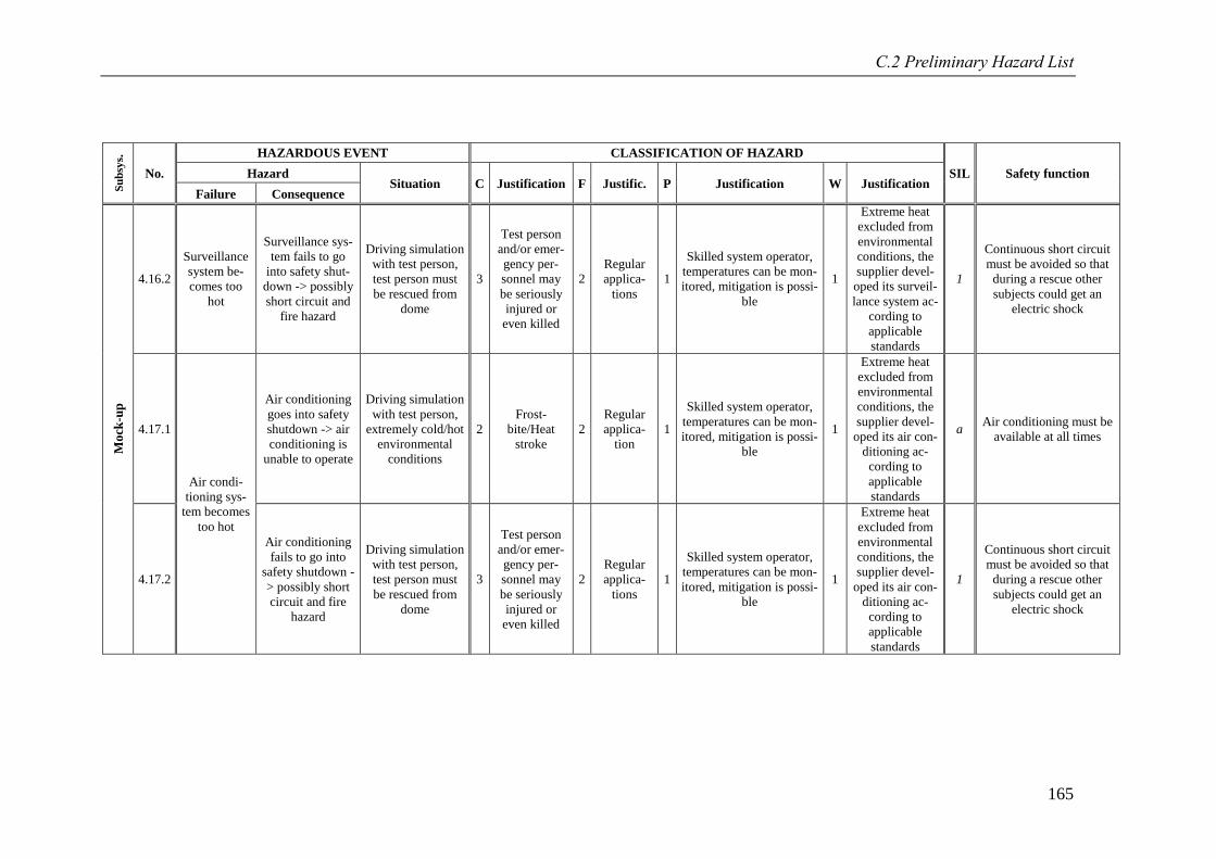
C.2 Preliminary Hazard List
165
Su
bsy
s.
No.
HAZARDOUS EVENT CLASSIFICATION OF HAZARD
SIL Safety function Hazard Situation C Justification F Justific. P Justification W Justification
Failure Consequence
Mo
ck-u
p
4.16.2
Surveillance
system be-
comes too
hot
Surveillance sys-
tem fails to go
into safety shut-
down -> possibly
short circuit and
fire hazard
Driving simulation
with test person,
test person must
be rescued from
dome
3
Test person
and/or emer-
gency per-
sonnel may
be seriously
injured or
even killed
2
Regular
applica-
tions
1
Skilled system operator,
temperatures can be mon-
itored, mitigation is possi-
ble
1
Extreme heat
excluded from
environmental
conditions, the
supplier devel-
oped its surveil-
lance system ac-
cording to
applicable
standards
1
Continuous short circuit
must be avoided so that
during a rescue other
subjects could get an
electric shock
4.17.1
Air condi-
tioning sys-
tem becomes
too hot
Air conditioning
goes into safety
shutdown -> air
conditioning is
unable to operate
Driving simulation
with test person,
extremely cold/hot
environmental
conditions
2
Frost-
bite/Heat
stroke
2
Regular
applica-
tion
1
Skilled system operator,
temperatures can be mon-
itored, mitigation is possi-
ble
1
Extreme heat
excluded from
environmental
conditions, the
supplier devel-
oped its air con-
ditioning ac-
cording to
applicable
standards
a Air conditioning must be
available at all times
4.17.2
Air conditioning
fails to go into
safety shutdown -
> possibly short
circuit and fire
hazard
Driving simulation
with test person,
test person must
be rescued from
dome
3
Test person
and/or emer-
gency per-
sonnel may
be seriously
injured or
even killed
2
Regular
applica-
tions
1
Skilled system operator,
temperatures can be mon-
itored, mitigation is possi-
ble
1
Extreme heat
excluded from
environmental
conditions, the
supplier devel-
oped its air con-
ditioning ac-
cording to
applicable
standards
1
Continuous short circuit
must be avoided so that
during a rescue other
subjects could get an
electric shock
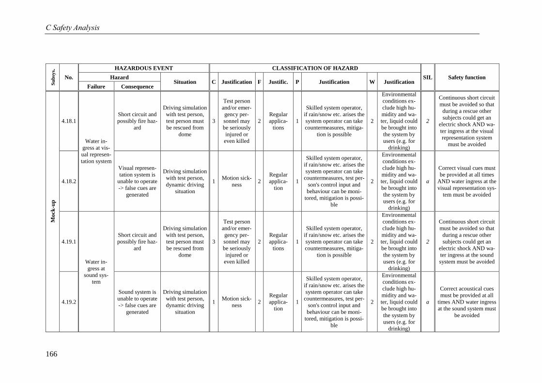
C Safety Analysis
166
Su
bsy
s.
No.
HAZARDOUS EVENT CLASSIFICATION OF HAZARD
SIL Safety function Hazard Situation C Justification F Justific. P Justification W Justification
Failure Consequence
Mo
ck-u
p
4.18.1
Water in-
gress at vis-
ual represen-
tation system
Short circuit and
possibly fire haz-
ard
Driving simulation
with test person,
test person must
be rescued from
dome
3
Test person
and/or emer-
gency per-
sonnel may
be seriously
injured or
even killed
2
Regular
applica-
tions
1
Skilled system operator,
if rain/snow etc. arises the
system operator can take
countermeasures, mitiga-
tion is possible
2
Environmental
conditions ex-
clude high hu-
midity and wa-
ter, liquid could
be brought into
the system by
users (e.g. for
drinking)
2
Continuous short circuit
must be avoided so that
during a rescue other
subjects could get an
electric shock AND wa-
ter ingress at the visual
representation system
must be avoided
4.18.2
Visual represen-
tation system is
unable to operate
-> false cues are
generated
Driving simulation
with test person,
dynamic driving
situation
1 Motion sick-
ness 2
Regular
applica-
tion
1
Skilled system operator,
if rain/snow etc. arises the
system operator can take
countermeasures, test per-
son's control input and
behaviour can be moni-
tored, mitigation is possi-
ble
2
Environmental
conditions ex-
clude high hu-
midity and wa-
ter, liquid could
be brought into
the system by
users (e.g. for
drinking)
a
Correct visual cues must
be provided at all times
AND water ingress at the
visual representation sys-
tem must be avoided
4.19.1
Water in-
gress at
sound sys-
tem
Short circuit and
possibly fire haz-
ard
Driving simulation
with test person,
test person must
be rescued from
dome
3
Test person
and/or emer-
gency per-
sonnel may
be seriously
injured or
even killed
2
Regular
applica-
tions
1
Skilled system operator,
if rain/snow etc. arises the
system operator can take
countermeasures, mitiga-
tion is possible
2
Environmental
conditions ex-
clude high hu-
midity and wa-
ter, liquid could
be brought into
the system by
users (e.g. for
drinking)
2
Continuous short circuit
must be avoided so that
during a rescue other
subjects could get an
electric shock AND wa-
ter ingress at the sound
system must be avoided
4.19.2
Sound system is
unable to operate
-> false cues are
generated
Driving simulation
with test person,
dynamic driving
situation
1 Motion sick-
ness 2
Regular
applica-
tion
1
Skilled system operator,
if rain/snow etc. arises the
system operator can take
countermeasures, test per-
son's control input and
behaviour can be moni-
tored, mitigation is possi-
ble
2
Environmental
conditions ex-
clude high hu-
midity and wa-
ter, liquid could
be brought into
the system by
users (e.g. for
drinking)
a
Correct acoustical cues
must be provided at all
times AND water ingress
at the sound system must
be avoided
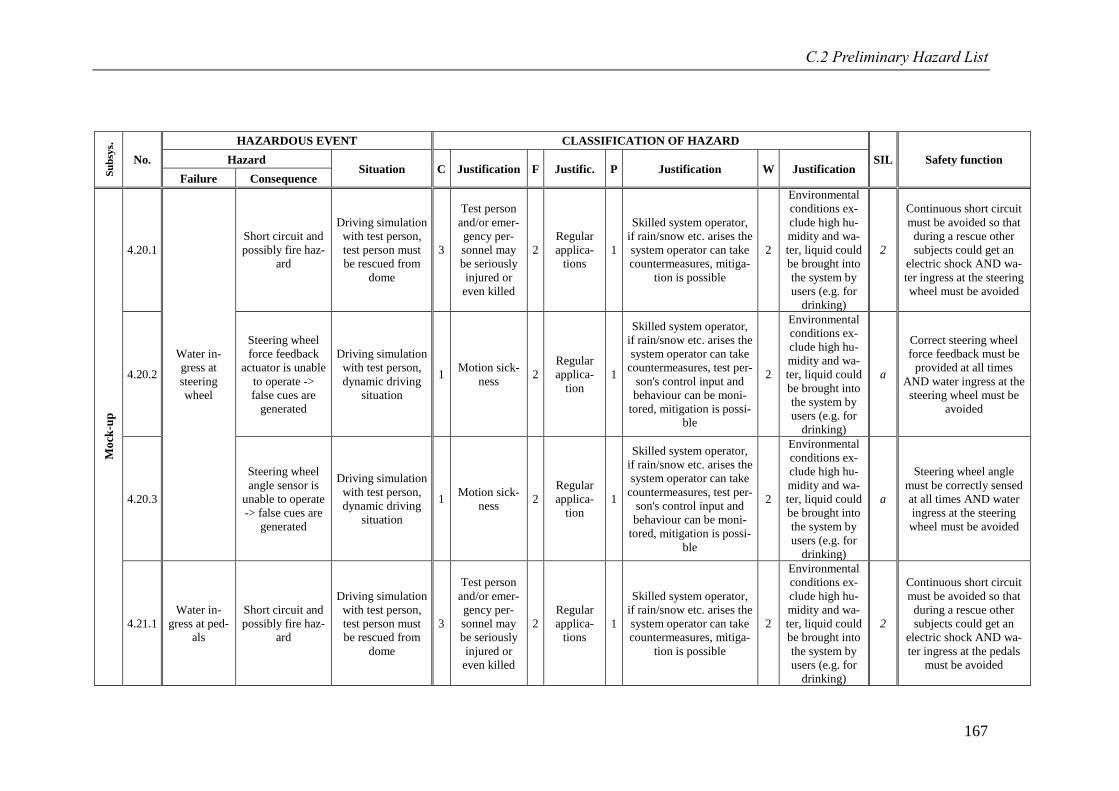
C.2 Preliminary Hazard List
167
Su
bsy
s.
No.
HAZARDOUS EVENT CLASSIFICATION OF HAZARD
SIL Safety function Hazard Situation C Justification F Justific. P Justification W Justification
Failure Consequence
Mo
ck-u
p
4.20.1
Water in-
gress at
steering
wheel
Short circuit and
possibly fire haz-
ard
Driving simulation
with test person,
test person must
be rescued from
dome
3
Test person
and/or emer-
gency per-
sonnel may
be seriously
injured or
even killed
2
Regular
applica-
tions
1
Skilled system operator,
if rain/snow etc. arises the
system operator can take
countermeasures, mitiga-
tion is possible
2
Environmental
conditions ex-
clude high hu-
midity and wa-
ter, liquid could
be brought into
the system by
users (e.g. for
drinking)
2
Continuous short circuit
must be avoided so that
during a rescue other
subjects could get an
electric shock AND wa-
ter ingress at the steering
wheel must be avoided
4.20.2
Steering wheel
force feedback
actuator is unable
to operate ->
false cues are
generated
Driving simulation
with test person,
dynamic driving
situation
1 Motion sick-
ness 2
Regular
applica-
tion
1
Skilled system operator,
if rain/snow etc. arises the
system operator can take
countermeasures, test per-
son's control input and
behaviour can be moni-
tored, mitigation is possi-
ble
2
Environmental
conditions ex-
clude high hu-
midity and wa-
ter, liquid could
be brought into
the system by
users (e.g. for
drinking)
a
Correct steering wheel
force feedback must be
provided at all times
AND water ingress at the
steering wheel must be
avoided
4.20.3
Steering wheel
angle sensor is
unable to operate
-> false cues are
generated
Driving simulation
with test person,
dynamic driving
situation
1 Motion sick-
ness 2
Regular
applica-
tion
1
Skilled system operator,
if rain/snow etc. arises the
system operator can take
countermeasures, test per-
son's control input and
behaviour can be moni-
tored, mitigation is possi-
ble
2
Environmental
conditions ex-
clude high hu-
midity and wa-
ter, liquid could
be brought into
the system by
users (e.g. for
drinking)
a
Steering wheel angle
must be correctly sensed
at all times AND water
ingress at the steering
wheel must be avoided
4.21.1
Water in-
gress at ped-
als
Short circuit and
possibly fire haz-
ard
Driving simulation
with test person,
test person must
be rescued from
dome
3
Test person
and/or emer-
gency per-
sonnel may
be seriously
injured or
even killed
2
Regular
applica-
tions
1
Skilled system operator,
if rain/snow etc. arises the
system operator can take
countermeasures, mitiga-
tion is possible
2
Environmental
conditions ex-
clude high hu-
midity and wa-
ter, liquid could
be brought into
the system by
users (e.g. for
drinking)
2
Continuous short circuit
must be avoided so that
during a rescue other
subjects could get an
electric shock AND wa-
ter ingress at the pedals
must be avoided
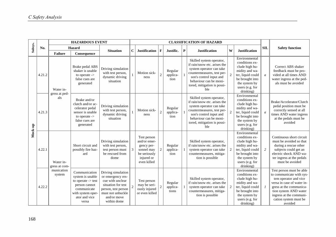
C Safety Analysis
168
Su
bsy
s.
No.
HAZARDOUS EVENT CLASSIFICATION OF HAZARD
SIL Safety function Hazard Situation C Justification F Justific. P Justification W Justification
Failure Consequence
Mo
ck-u
p
4.21.2
Water in-
gress at ped-
als
Brake pedal ABS
shaker is unable
to operate ->
false cues are
generated
Driving simulation
with test person,
dynamic driving
situation
1 Motion sick-
ness 2
Regular
applica-
tion
1
Skilled system operator,
if rain/snow etc. arises the
system operator can take
countermeasures, test per-
son's control input and
behaviour can be moni-
tored, mitigation is possi-
ble
2
Environmental
conditions ex-
clude high hu-
midity and wa-
ter, liquid could
be brought into
the system by
users (e.g. for
drinking)
a
Correct ABS shaker
feedback must be pro-
vided at all times AND
water ingress at the ped-
als must be avoided
4.21.3
Brake and/or
clutch and/or ac-
celerator pedal
sensor is unable
to operate ->
false cues are
generated
Driving simulation
with test person,
dynamic driving
situation
1 Motion sick-
ness 2
Regular
applica-
tion
1
Skilled system operator,
if rain/snow etc. arises the
system operator can take
countermeasures, test per-
son's control input and
behaviour can be moni-
tored, mitigation is possi-
ble
2
Environmental
conditions ex-
clude high hu-
midity and wa-
ter, liquid could
be brought into
the system by
users (e.g. for
drinking)
a
Brake/Accelerator/Clutch
pedal position must be
correctly sensed at all
times AND water ingress
at the pedals must be
avoided
4.22.1
Water in-
gress at com-
munication
system
Short circuit and
possibly fire haz-
ard
Driving simulation
with test person,
test person must
be rescued from
dome
3
Test person
and/or emer-
gency per-
sonnel may
be seriously
injured or
even killed
2
Regular
applica-
tion
1
Skilled system operator,
if rain/snow etc. arises the
system operator can take
countermeasures, mitiga-
tion is possible
2
Environmental
conditions ex-
clude high hu-
midity and wa-
ter, liquid could
be brought into
the system by
users (e.g. for
drinking)
2
Continuous short circuit
must be avoided so that
during a rescue other
subjects could get an
electric shock AND wa-
ter ingress at the pedals
must be avoided
4.22.2
Communication
system is unable
to operate -> test
person cannot
communicate
with system oper-
ator and vice
versa
Driving simulation
or emergency res-
cue with unclear
situation for test
person, test person
must not unbuckle
and/or move
within dome
2
Test person
may be seri-
ously injured
or even killed
2
Regular
applica-
tions
1
Skilled system operator,
if rain/snow etc. arises the
system operator can take
countermeasures, mitiga-
tion is possible
2
Environmental
conditions ex-
clude high hu-
midity and wa-
ter, liquid could
be brought into
the system by
users (e.g. for
drinking)
1
Test person must be able
to communicate with sys-
tem operator and vice
versa in case of water in-
gress at the communica-
tion system AND water
ingress at the communi-
cation system must be
avoided
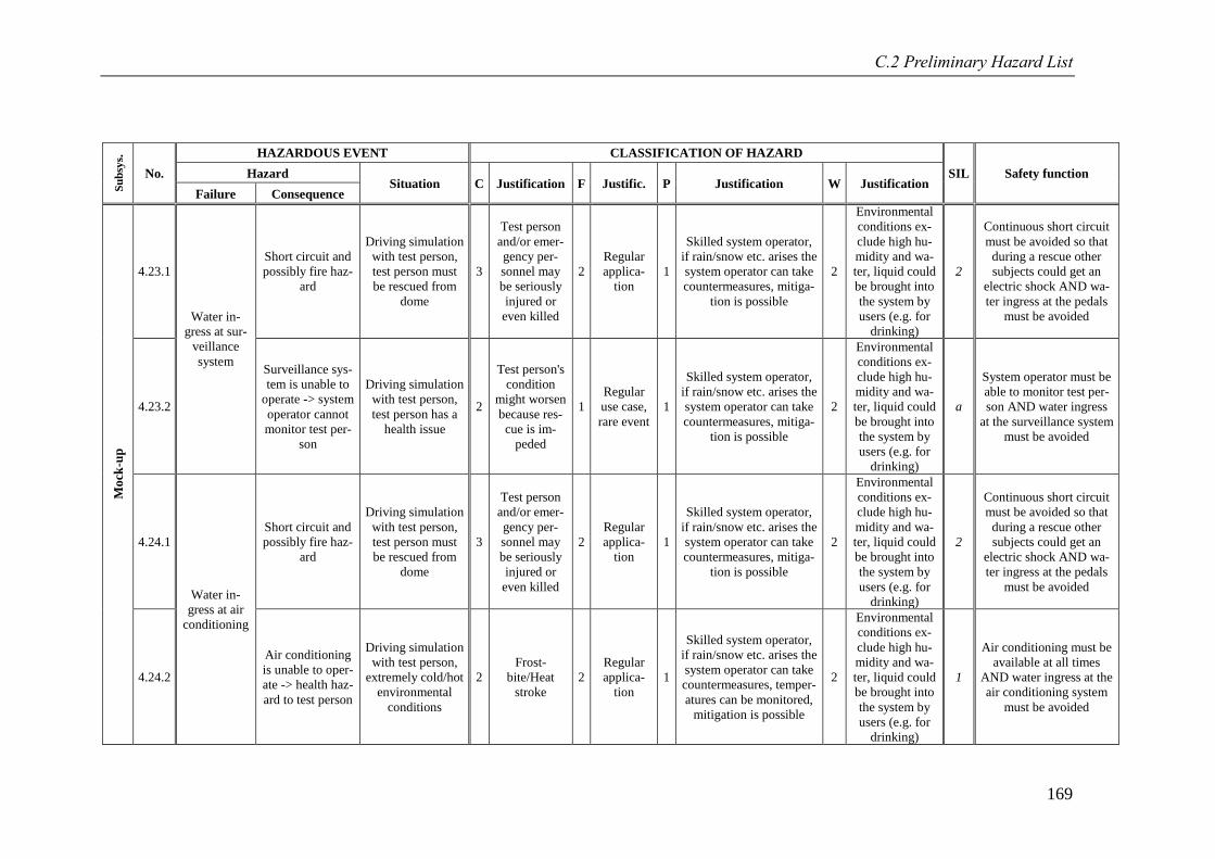
C.2 Preliminary Hazard List
169
Su
bsy
s.
No.
HAZARDOUS EVENT CLASSIFICATION OF HAZARD
SIL Safety function Hazard Situation C Justification F Justific. P Justification W Justification
Failure Consequence
Mo
ck-u
p
4.23.1
Water in-
gress at sur-
veillance
system
Short circuit and
possibly fire haz-
ard
Driving simulation
with test person,
test person must
be rescued from
dome
3
Test person
and/or emer-
gency per-
sonnel may
be seriously
injured or
even killed
2
Regular
applica-
tion
1
Skilled system operator,
if rain/snow etc. arises the
system operator can take
countermeasures, mitiga-
tion is possible
2
Environmental
conditions ex-
clude high hu-
midity and wa-
ter, liquid could
be brought into
the system by
users (e.g. for
drinking)
2
Continuous short circuit
must be avoided so that
during a rescue other
subjects could get an
electric shock AND wa-
ter ingress at the pedals
must be avoided
4.23.2
Surveillance sys-
tem is unable to
operate -> system
operator cannot
monitor test per-
son
Driving simulation
with test person,
test person has a
health issue
2
Test person's
condition
might worsen
because res-
cue is im-
peded
1
Regular
use case,
rare event
1
Skilled system operator,
if rain/snow etc. arises the
system operator can take
countermeasures, mitiga-
tion is possible
2
Environmental
conditions ex-
clude high hu-
midity and wa-
ter, liquid could
be brought into
the system by
users (e.g. for
drinking)
a
System operator must be
able to monitor test per-
son AND water ingress
at the surveillance system
must be avoided
4.24.1
Water in-
gress at air
conditioning
Short circuit and
possibly fire haz-
ard
Driving simulation
with test person,
test person must
be rescued from
dome
3
Test person
and/or emer-
gency per-
sonnel may
be seriously
injured or
even killed
2
Regular
applica-
tion
1
Skilled system operator,
if rain/snow etc. arises the
system operator can take
countermeasures, mitiga-
tion is possible
2
Environmental
conditions ex-
clude high hu-
midity and wa-
ter, liquid could
be brought into
the system by
users (e.g. for
drinking)
2
Continuous short circuit
must be avoided so that
during a rescue other
subjects could get an
electric shock AND wa-
ter ingress at the pedals
must be avoided
4.24.2
Air conditioning
is unable to oper-
ate -> health haz-
ard to test person
Driving simulation
with test person,
extremely cold/hot
environmental
conditions
2
Frost-
bite/Heat
stroke
2
Regular
applica-
tion
1
Skilled system operator,
if rain/snow etc. arises the
system operator can take
countermeasures, temper-
atures can be monitored,
mitigation is possible
2
Environmental
conditions ex-
clude high hu-
midity and wa-
ter, liquid could
be brought into
the system by
users (e.g. for
drinking)
1
Air conditioning must be
available at all times
AND water ingress at the
air conditioning system
must be avoided
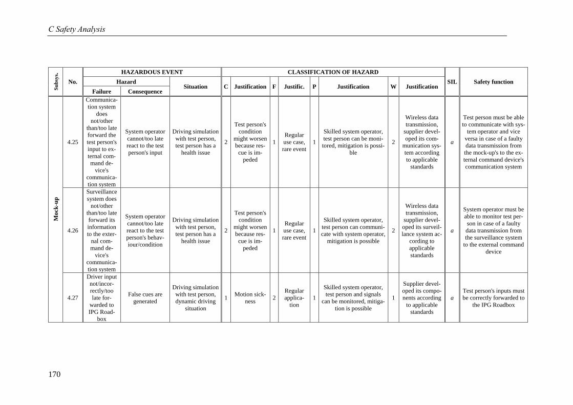
C Safety Analysis
170
Su
bsy
s.
No.
HAZARDOUS EVENT CLASSIFICATION OF HAZARD
SIL Safety function Hazard Situation C Justification F Justific. P Justification W Justification
Failure Consequence
Mo
ck-u
p
4.25
Communica-
tion system
does
not/other
than/too late
forward the
test person's
input to ex-
ternal com-
mand de-
vice's
communica-
tion system
System operator
cannot/too late
react to the test
person's input
Driving simulation
with test person,
test person has a
health issue
2
Test person's
condition
might worsen
because res-
cue is im-
peded
1
Regular
use case,
rare event
1
Skilled system operator,
test person can be moni-
tored, mitigation is possi-
ble
2
Wireless data
transmission,
supplier devel-
oped its com-
munication sys-
tem according
to applicable
standards
a
Test person must be able
to communicate with sys-
tem operator and vice
versa in case of a faulty
data transmission from
the mock-up's to the ex-
ternal command device's
communication system
4.26
Surveillance
system does
not/other
than/too late
forward its
information
to the exter-
nal com-
mand de-
vice's
communica-
tion system
System operator
cannot/too late
react to the test
person's behav-
iour/condition
Driving simulation
with test person,
test person has a
health issue
2
Test person's
condition
might worsen
because res-
cue is im-
peded
1
Regular
use case,
rare event
1
Skilled system operator,
test person can communi-
cate with system operator,
mitigation is possible
2
Wireless data
transmission,
supplier devel-
oped its surveil-
lance system ac-
cording to
applicable
standards
a
System operator must be
able to monitor test per-
son in case of a faulty
data transmission from
the surveillance system
to the external command
device
4.27
Driver input
not/incor-
rectly/too
late for-
warded to
IPG Road-
box
False cues are
generated
Driving simulation
with test person,
dynamic driving
situation
1 Motion sick-
ness 2
Regular
applica-
tion
1
Skilled system operator,
test person and signals
can be monitored, mitiga-
tion is possible
1
Supplier devel-
oped its compo-
nents according
to applicable
standards
a
Test person's inputs must
be correctly forwarded to
the IPG Roadbox
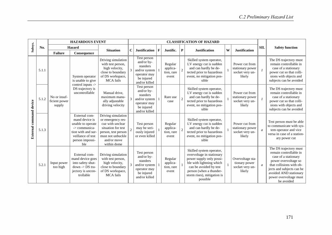
C.2 Preliminary Hazard List
171
Su
bsy
s.
No.
HAZARDOUS EVENT CLASSIFICATION OF HAZARD
SIL Safety function Hazard Situation C Justification F Justific. P Justification W Justification
Failure Consequence
Ex
tern
al
com
ma
nd
dev
ice
5.1.1
No or insuf-
ficient power
supply
System operator
is unable to give
control inputs ->
DS trajectory is
uncontrollable
Driving simulation
with test person,
high velocity,
close to boundary
of DS workspace,
MCA fails
3
Test person
and/or by-
standers
and/or system
operator may
be injured
and/or killed
1
Regular
applica-
tion, rare
event
2
Skilled system operator,
LV energy cut is sudden
and can hardly be de-
tected prior to hazardous
event, no mitigation pos-
sible
1
Power cut from
stationary power
socket very un-
likely
1
The DS trajectory must
remain controllable in
case of a stationary
power cut so that colli-
sions with objects and
subjects can be avoided
5.1.2
Manual drive,
maximum manu-
ally adjustable
driving velocity
3
Test person
and/or by-
standers
and/or system
operator may
be injured
and/or killed
1 Rare use
case 2
Skilled system operator,
LV energy cut is sudden
and can hardly be de-
tected prior to hazardous
event, no mitigation pos-
sible
1
Power cut from
stationary power
socket very un-
likely
1
The DS trajectory must
remain controllable in
case of a stationary
power cut so that colli-
sions with objects and
subjects can be avoided
5.1.3
External com-
mand device is
unable to operate
-> communica-
tion with and sur-
veillance of test
person impossi-
ble
Driving simulation
or emergency res-
cue with unclear
situation for test
person, test person
must not unbuckle
and/or move
within dome
2
Test person
may be seri-
ously injured
or even killed
1
Regular
applica-
tion, rare
event
2
Skilled system operator,
LV energy cut is sudden
and can hardly be de-
tected prior to hazardous
event, no mitigation pos-
sible
1
Power cut from
stationary power
socket very un-
likely
a
Test person must be able
to communicate with sys-
tem operator and vice
versa in case of a station-
ary power cut
5.2.1 Input power
too high
External com-
mand device goes
into safety shut-
down -> DS tra-
jectory is uncon-
trollable
Driving simulation
with test person,
high velocity,
close to boundary
of DS workspace,
MCA fails
3
Test person
and/or by-
standers
and/or system
operator may
be injured
and/or killed
1
Regular
applica-
tion, rare
event
1
Skilled system operator,
overvoltage in stationary
power supply only possi-
ble with lightning which
can be avoided by test
person (when a thunder-
storm rises), mitigation is
possible
1
Overvoltage sta-
tionary power
socket very un-
likely
a
The DS trajectory must
remain controllable in
case of a stationary
power overvoltage so
that collisions with ob-
jects and subjects can be
avoided AND stationary
power overvoltage must
be avoided
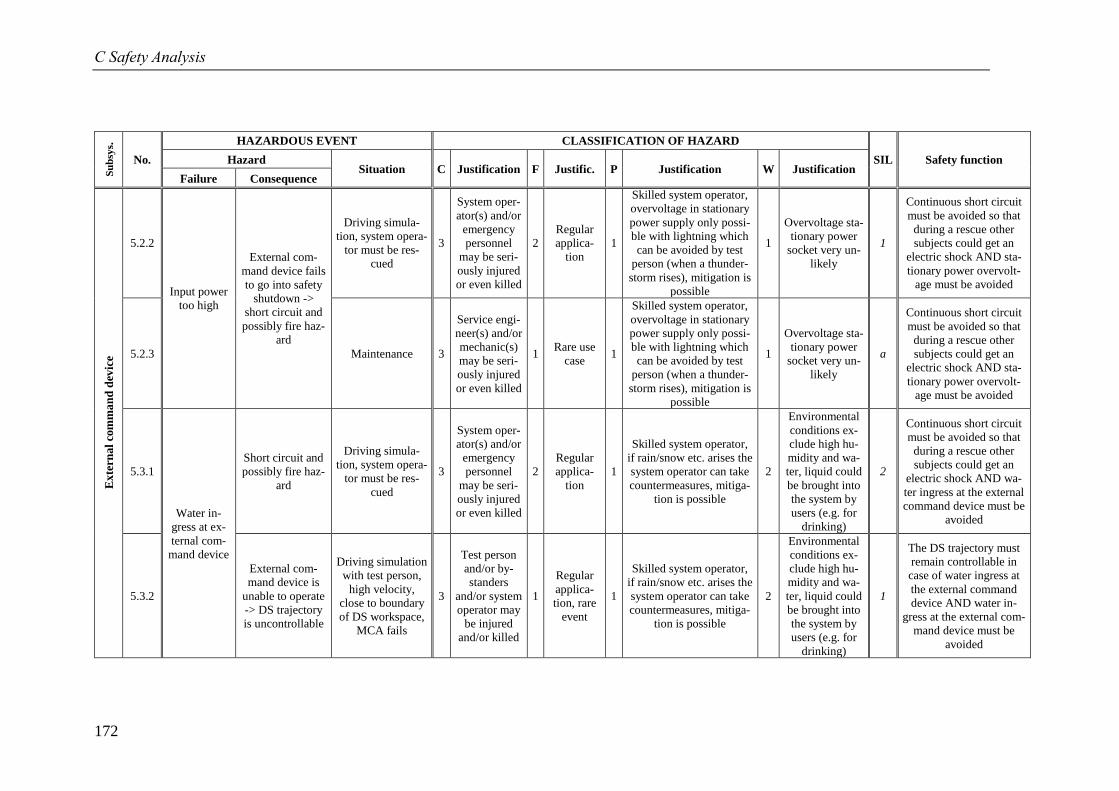
C Safety Analysis
172
Su
bsy
s.
No.
HAZARDOUS EVENT CLASSIFICATION OF HAZARD
SIL Safety function Hazard Situation C Justification F Justific. P Justification W Justification
Failure Consequence
Ex
tern
al
com
ma
nd
dev
ice
5.2.2
Input power
too high
External com-
mand device fails
to go into safety
shutdown ->
short circuit and
possibly fire haz-
ard
Driving simula-
tion, system opera-
tor must be res-
cued
3
System oper-
ator(s) and/or
emergency
personnel
may be seri-
ously injured
or even killed
2
Regular
applica-
tion
1
Skilled system operator,
overvoltage in stationary
power supply only possi-
ble with lightning which
can be avoided by test
person (when a thunder-
storm rises), mitigation is
possible
1
Overvoltage sta-
tionary power
socket very un-
likely
1
Continuous short circuit
must be avoided so that
during a rescue other
subjects could get an
electric shock AND sta-
tionary power overvolt-
age must be avoided
5.2.3 Maintenance 3
Service engi-
neer(s) and/or
mechanic(s)
may be seri-
ously injured
or even killed
1 Rare use
case 1
Skilled system operator,
overvoltage in stationary
power supply only possi-
ble with lightning which
can be avoided by test
person (when a thunder-
storm rises), mitigation is
possible
1
Overvoltage sta-
tionary power
socket very un-
likely
a
Continuous short circuit
must be avoided so that
during a rescue other
subjects could get an
electric shock AND sta-
tionary power overvolt-
age must be avoided
5.3.1
Water in-
gress at ex-
ternal com-
mand device
Short circuit and
possibly fire haz-
ard
Driving simula-
tion, system opera-
tor must be res-
cued
3
System oper-
ator(s) and/or
emergency
personnel
may be seri-
ously injured
or even killed
2
Regular
applica-
tion
1
Skilled system operator,
if rain/snow etc. arises the
system operator can take
countermeasures, mitiga-
tion is possible
2
Environmental
conditions ex-
clude high hu-
midity and wa-
ter, liquid could
be brought into
the system by
users (e.g. for
drinking)
2
Continuous short circuit
must be avoided so that
during a rescue other
subjects could get an
electric shock AND wa-
ter ingress at the external
command device must be
avoided
5.3.2
External com-
mand device is
unable to operate
-> DS trajectory
is uncontrollable
Driving simulation
with test person,
high velocity,
close to boundary
of DS workspace,
MCA fails
3
Test person
and/or by-
standers
and/or system
operator may
be injured
and/or killed
1
Regular
applica-
tion, rare
event
1
Skilled system operator,
if rain/snow etc. arises the
system operator can take
countermeasures, mitiga-
tion is possible
2
Environmental
conditions ex-
clude high hu-
midity and wa-
ter, liquid could
be brought into
the system by
users (e.g. for
drinking)
1
The DS trajectory must
remain controllable in
case of water ingress at
the external command
device AND water in-
gress at the external com-
mand device must be
avoided
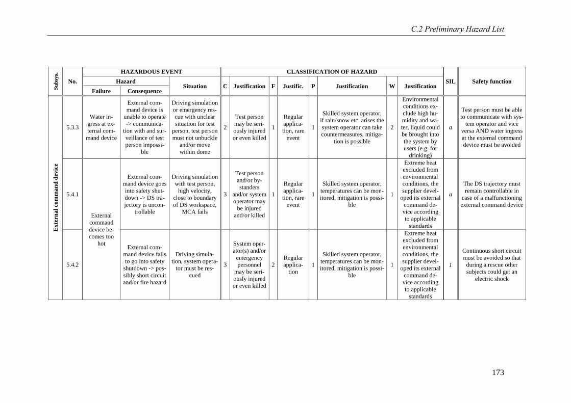
C.2 Preliminary Hazard List
173
Su
bsy
s.
No.
HAZARDOUS EVENT CLASSIFICATION OF HAZARD
SIL Safety function Hazard Situation C Justification F Justific. P Justification W Justification
Failure Consequence
Ex
tern
al
com
ma
nd
dev
ice
5.3.3
Water in-
gress at ex-
ternal com-
mand device
External com-
mand device is
unable to operate
-> communica-
tion with and sur-
veillance of test
person impossi-
ble
Driving simulation
or emergency res-
cue with unclear
situation for test
person, test person
must not unbuckle
and/or move
within dome
2
Test person
may be seri-
ously injured
or even killed
1
Regular
applica-
tion, rare
event
1
Skilled system operator,
if rain/snow etc. arises the
system operator can take
countermeasures, mitiga-
tion is possible
2
Environmental
conditions ex-
clude high hu-
midity and wa-
ter, liquid could
be brought into
the system by
users (e.g. for
drinking)
a
Test person must be able
to communicate with sys-
tem operator and vice
versa AND water ingress
at the external command
device must be avoided
5.4.1
External
command
device be-
comes too
hot
External com-
mand device goes
into safety shut-
down -> DS tra-
jectory is uncon-
trollable
Driving simulation
with test person,
high velocity,
close to boundary
of DS workspace,
MCA fails
3
Test person
and/or by-
standers
and/or system
operator may
be injured
and/or killed
1
Regular
applica-
tion, rare
event
1
Skilled system operator,
temperatures can be mon-
itored, mitigation is possi-
ble
1
Extreme heat
excluded from
environmental
conditions, the
supplier devel-
oped its external
command de-
vice according
to applicable
standards
a
The DS trajectory must
remain controllable in
case of a malfunctioning
external command device
5.4.2
External com-
mand device fails
to go into safety
shutdown -> pos-
sibly short circuit
and/or fire hazard
Driving simula-
tion, system opera-
tor must be res-
cued
3
System oper-
ator(s) and/or
emergency
personnel
may be seri-
ously injured
or even killed
2
Regular
applica-
tion
1
Skilled system operator,
temperatures can be mon-
itored, mitigation is possi-
ble
1
Extreme heat
excluded from
environmental
conditions, the
supplier devel-
oped its external
command de-
vice according
to applicable
standards
1
Continuous short circuit
must be avoided so that
during a rescue other
subjects could get an
electric shock
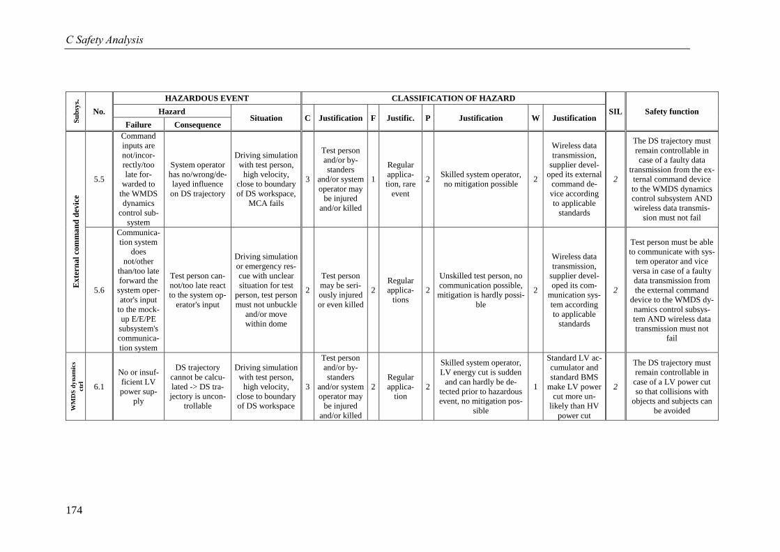
C Safety Analysis
174
Su
bsy
s.
No.
HAZARDOUS EVENT CLASSIFICATION OF HAZARD
SIL Safety function Hazard Situation C Justification F Justific. P Justification W Justification
Failure Consequence
Ex
tern
al
com
ma
nd
dev
ice
5.5
Command
inputs are
not/incor-
rectly/too
late for-
warded to
the WMDS
dynamics
control sub-
system
System operator
has no/wrong/de-
layed influence
on DS trajectory
Driving simulation
with test person,
high velocity,
close to boundary
of DS workspace,
MCA fails
3
Test person
and/or by-
standers
and/or system
operator may
be injured
and/or killed
1
Regular
applica-
tion, rare
event
2 Skilled system operator,
no mitigation possible 2
Wireless data
transmission,
supplier devel-
oped its external
command de-
vice according
to applicable
standards
2
The DS trajectory must
remain controllable in
case of a faulty data
transmission from the ex-
ternal command device
to the WMDS dynamics
control subsystem AND
wireless data transmis-
sion must not fail
5.6
Communica-
tion system
does
not/other
than/too late
forward the
system oper-
ator's input
to the mock-
up E/E/PE
subsystem's
communica-
tion system
Test person can-
not/too late react
to the system op-
erator's input
Driving simulation
or emergency res-
cue with unclear
situation for test
person, test person
must not unbuckle
and/or move
within dome
2
Test person
may be seri-
ously injured
or even killed
2
Regular
applica-
tions
2
Unskilled test person, no
communication possible,
mitigation is hardly possi-
ble
2
Wireless data
transmission,
supplier devel-
oped its com-
munication sys-
tem according
to applicable
standards
2
Test person must be able
to communicate with sys-
tem operator and vice
versa in case of a faulty
data transmission from
the external command
device to the WMDS dy-
namics control subsys-
tem AND wireless data
transmission must not
fail
WM
DS
dy
nam
ics
ctr
l
6.1
No or insuf-
ficient LV
power sup-
ply
DS trajectory
cannot be calcu-
lated -> DS tra-
jectory is uncon-
trollable
Driving simulation
with test person,
high velocity,
close to boundary
of DS workspace
3
Test person
and/or by-
standers
and/or system
operator may
be injured
and/or killed
2
Regular
applica-
tion
2
Skilled system operator,
LV energy cut is sudden
and can hardly be de-
tected prior to hazardous
event, no mitigation pos-
sible
1
Standard LV ac-
cumulator and
standard BMS
make LV power
cut more un-
likely than HV
power cut
2
The DS trajectory must
remain controllable in
case of a LV power cut
so that collisions with
objects and subjects can
be avoided
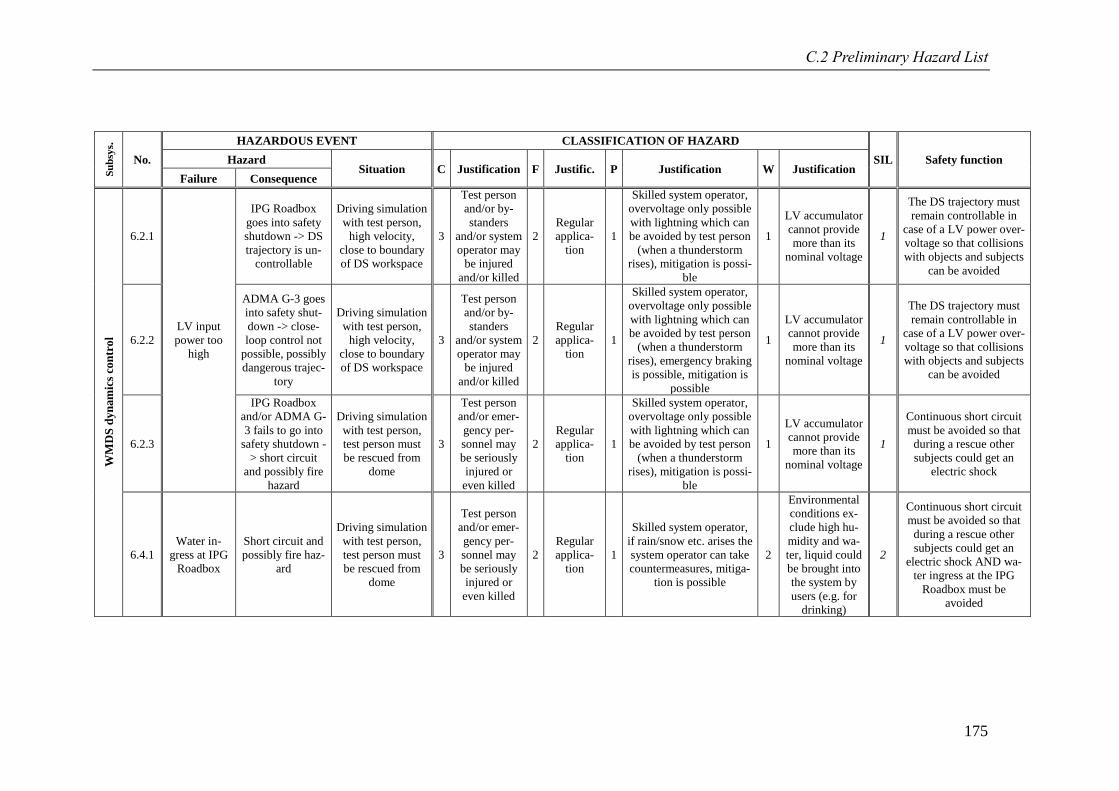
C.2 Preliminary Hazard List
175
Su
bsy
s.
No.
HAZARDOUS EVENT CLASSIFICATION OF HAZARD
SIL Safety function Hazard Situation C Justification F Justific. P Justification W Justification
Failure Consequence
WM
DS
dyn
am
ics
con
tro
l
6.2.1
LV input
power too
high
IPG Roadbox
goes into safety
shutdown -> DS
trajectory is un-
controllable
Driving simulation
with test person,
high velocity,
close to boundary
of DS workspace
3
Test person
and/or by-
standers
and/or system
operator may
be injured
and/or killed
2
Regular
applica-
tion
1
Skilled system operator,
overvoltage only possible
with lightning which can
be avoided by test person
(when a thunderstorm
rises), mitigation is possi-
ble
1
LV accumulator
cannot provide
more than its
nominal voltage
1
The DS trajectory must
remain controllable in
case of a LV power over-
voltage so that collisions
with objects and subjects
can be avoided
6.2.2
ADMA G-3 goes
into safety shut-
down -> close-
loop control not
possible, possibly
dangerous trajec-
tory
Driving simulation
with test person,
high velocity,
close to boundary
of DS workspace
3
Test person
and/or by-
standers
and/or system
operator may
be injured
and/or killed
2
Regular
applica-
tion
1
Skilled system operator,
overvoltage only possible
with lightning which can
be avoided by test person
(when a thunderstorm
rises), emergency braking
is possible, mitigation is
possible
1
LV accumulator
cannot provide
more than its
nominal voltage
1
The DS trajectory must
remain controllable in
case of a LV power over-
voltage so that collisions
with objects and subjects
can be avoided
6.2.3
IPG Roadbox
and/or ADMA G-
3 fails to go into
safety shutdown -
> short circuit
and possibly fire
hazard
Driving simulation
with test person,
test person must
be rescued from
dome
3
Test person
and/or emer-
gency per-
sonnel may
be seriously
injured or
even killed
2
Regular
applica-
tion
1
Skilled system operator,
overvoltage only possible
with lightning which can
be avoided by test person
(when a thunderstorm
rises), mitigation is possi-
ble
1
LV accumulator
cannot provide
more than its
nominal voltage
1
Continuous short circuit
must be avoided so that
during a rescue other
subjects could get an
electric shock
6.4.1
Water in-
gress at IPG
Roadbox
Short circuit and
possibly fire haz-
ard
Driving simulation
with test person,
test person must
be rescued from
dome
3
Test person
and/or emer-
gency per-
sonnel may
be seriously
injured or
even killed
2
Regular
applica-
tion
1
Skilled system operator,
if rain/snow etc. arises the
system operator can take
countermeasures, mitiga-
tion is possible
2
Environmental
conditions ex-
clude high hu-
midity and wa-
ter, liquid could
be brought into
the system by
users (e.g. for
drinking)
2
Continuous short circuit
must be avoided so that
during a rescue other
subjects could get an
electric shock AND wa-
ter ingress at the IPG
Roadbox must be
avoided
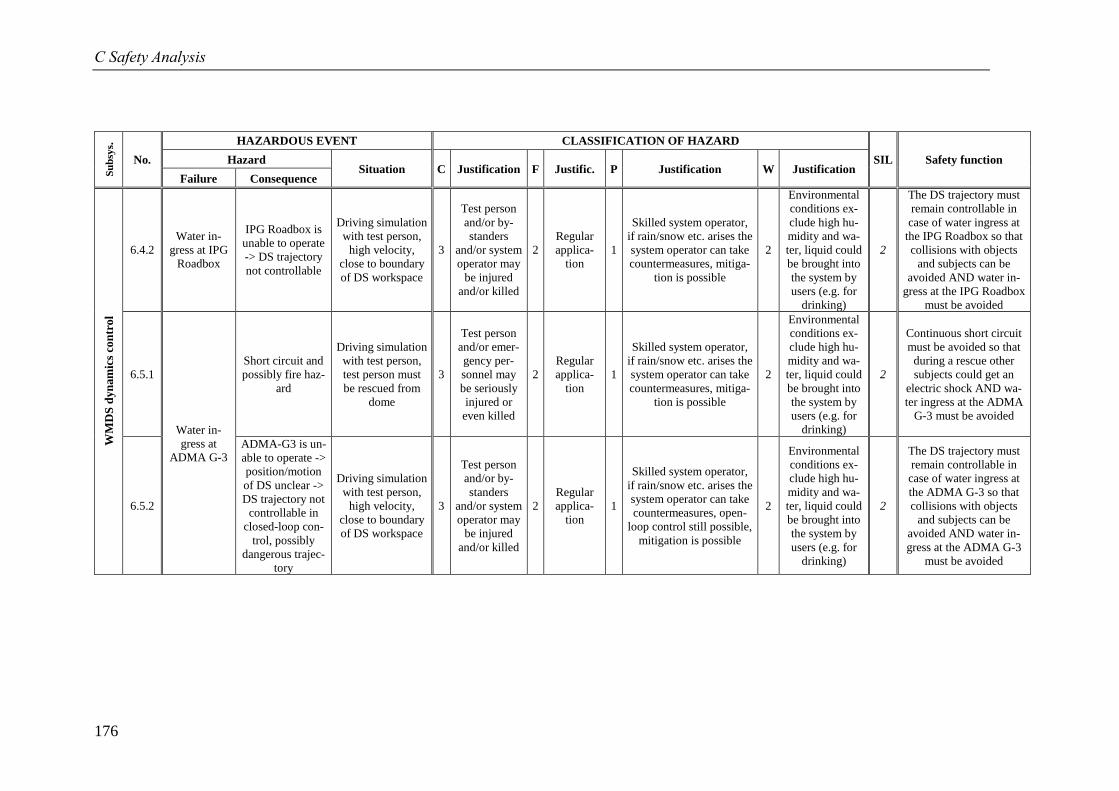
C Safety Analysis
176
Su
bsy
s.
No.
HAZARDOUS EVENT CLASSIFICATION OF HAZARD
SIL Safety function Hazard Situation C Justification F Justific. P Justification W Justification
Failure Consequence
WM
DS
dyn
am
ics
con
tro
l
6.4.2
Water in-
gress at IPG
Roadbox
IPG Roadbox is
unable to operate
-> DS trajectory
not controllable
Driving simulation
with test person,
high velocity,
close to boundary
of DS workspace
3
Test person
and/or by-
standers
and/or system
operator may
be injured
and/or killed
2
Regular
applica-
tion
1
Skilled system operator,
if rain/snow etc. arises the
system operator can take
countermeasures, mitiga-
tion is possible
2
Environmental
conditions ex-
clude high hu-
midity and wa-
ter, liquid could
be brought into
the system by
users (e.g. for
drinking)
2
The DS trajectory must
remain controllable in
case of water ingress at
the IPG Roadbox so that
collisions with objects
and subjects can be
avoided AND water in-
gress at the IPG Roadbox
must be avoided
6.5.1
Water in-
gress at
ADMA G-3
Short circuit and
possibly fire haz-
ard
Driving simulation
with test person,
test person must
be rescued from
dome
3
Test person
and/or emer-
gency per-
sonnel may
be seriously
injured or
even killed
2
Regular
applica-
tion
1
Skilled system operator,
if rain/snow etc. arises the
system operator can take
countermeasures, mitiga-
tion is possible
2
Environmental
conditions ex-
clude high hu-
midity and wa-
ter, liquid could
be brought into
the system by
users (e.g. for
drinking)
2
Continuous short circuit
must be avoided so that
during a rescue other
subjects could get an
electric shock AND wa-
ter ingress at the ADMA
G-3 must be avoided
6.5.2
ADMA-G3 is un-
able to operate ->
position/motion
of DS unclear ->
DS trajectory not
controllable in
closed-loop con-
trol, possibly
dangerous trajec-
tory
Driving simulation
with test person,
high velocity,
close to boundary
of DS workspace
3
Test person
and/or by-
standers
and/or system
operator may
be injured
and/or killed
2
Regular
applica-
tion
1
Skilled system operator,
if rain/snow etc. arises the
system operator can take
countermeasures, open-
loop control still possible,
mitigation is possible
2
Environmental
conditions ex-
clude high hu-
midity and wa-
ter, liquid could
be brought into
the system by
users (e.g. for
drinking)
2
The DS trajectory must
remain controllable in
case of water ingress at
the ADMA G-3 so that
collisions with objects
and subjects can be
avoided AND water in-
gress at the ADMA G-3
must be avoided
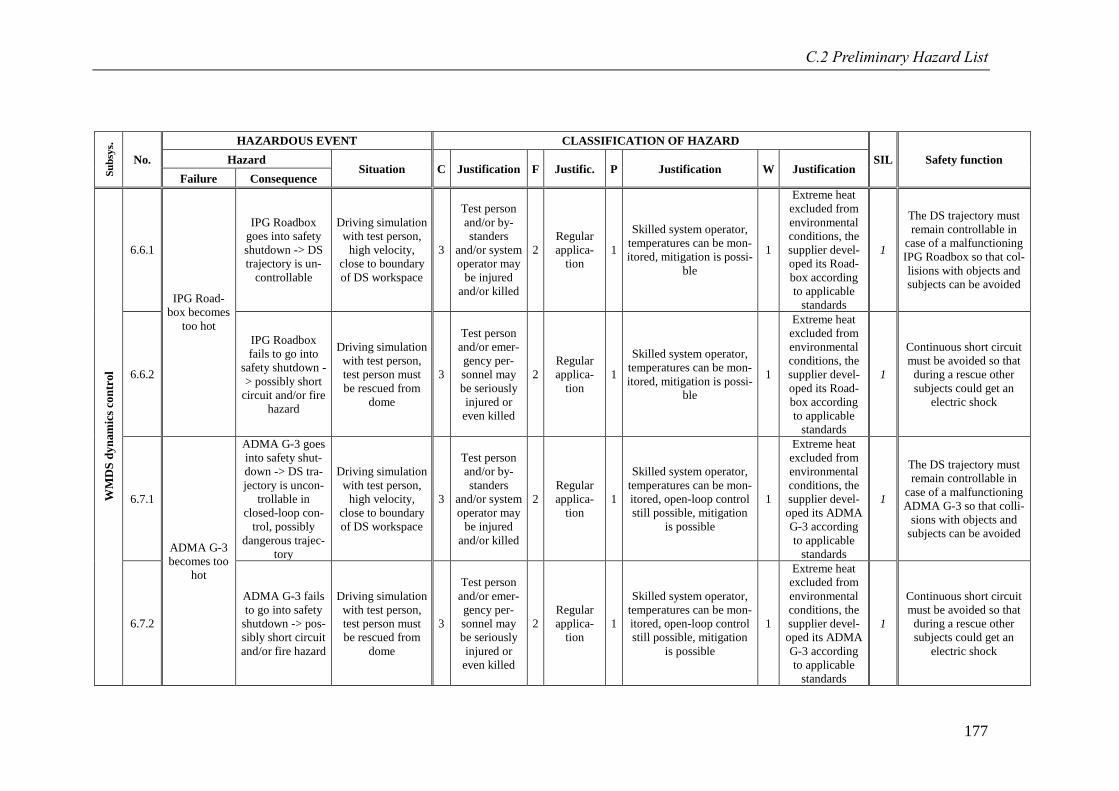
C.2 Preliminary Hazard List
177
Su
bsy
s.
No.
HAZARDOUS EVENT CLASSIFICATION OF HAZARD
SIL Safety function Hazard Situation C Justification F Justific. P Justification W Justification
Failure Consequence
WM
DS
dyn
am
ics
con
tro
l
6.6.1
IPG Road-
box becomes
too hot
IPG Roadbox
goes into safety
shutdown -> DS
trajectory is un-
controllable
Driving simulation
with test person,
high velocity,
close to boundary
of DS workspace
3
Test person
and/or by-
standers
and/or system
operator may
be injured
and/or killed
2
Regular
applica-
tion
1
Skilled system operator,
temperatures can be mon-
itored, mitigation is possi-
ble
1
Extreme heat
excluded from
environmental
conditions, the
supplier devel-
oped its Road-
box according
to applicable
standards
1
The DS trajectory must
remain controllable in
case of a malfunctioning
IPG Roadbox so that col-
lisions with objects and
subjects can be avoided
6.6.2
IPG Roadbox
fails to go into
safety shutdown -
> possibly short
circuit and/or fire
hazard
Driving simulation
with test person,
test person must
be rescued from
dome
3
Test person
and/or emer-
gency per-
sonnel may
be seriously
injured or
even killed
2
Regular
applica-
tion
1
Skilled system operator,
temperatures can be mon-
itored, mitigation is possi-
ble
1
Extreme heat
excluded from
environmental
conditions, the
supplier devel-
oped its Road-
box according
to applicable
standards
1
Continuous short circuit
must be avoided so that
during a rescue other
subjects could get an
electric shock
6.7.1
ADMA G-3
becomes too
hot
ADMA G-3 goes
into safety shut-
down -> DS tra-
jectory is uncon-
trollable in
closed-loop con-
trol, possibly
dangerous trajec-
tory
Driving simulation
with test person,
high velocity,
close to boundary
of DS workspace
3
Test person
and/or by-
standers
and/or system
operator may
be injured
and/or killed
2
Regular
applica-
tion
1
Skilled system operator,
temperatures can be mon-
itored, open-loop control
still possible, mitigation
is possible
1
Extreme heat
excluded from
environmental
conditions, the
supplier devel-
oped its ADMA
G-3 according
to applicable
standards
1
The DS trajectory must
remain controllable in
case of a malfunctioning
ADMA G-3 so that colli-
sions with objects and
subjects can be avoided
6.7.2
ADMA G-3 fails
to go into safety
shutdown -> pos-
sibly short circuit
and/or fire hazard
Driving simulation
with test person,
test person must
be rescued from
dome
3
Test person
and/or emer-
gency per-
sonnel may
be seriously
injured or
even killed
2
Regular
applica-
tion
1
Skilled system operator,
temperatures can be mon-
itored, open-loop control
still possible, mitigation
is possible
1
Extreme heat
excluded from
environmental
conditions, the
supplier devel-
oped its ADMA
G-3 according
to applicable
standards
1
Continuous short circuit
must be avoided so that
during a rescue other
subjects could get an
electric shock
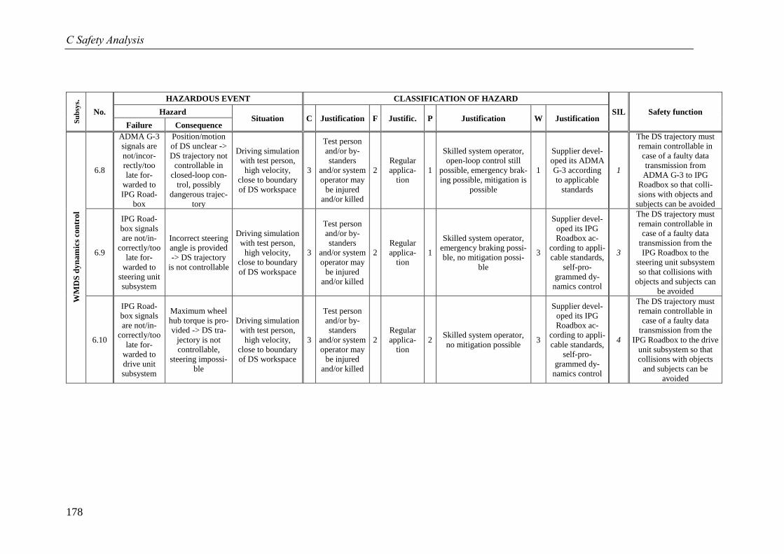
C Safety Analysis
178
Su
bsy
s.
No.
HAZARDOUS EVENT CLASSIFICATION OF HAZARD
SIL Safety function Hazard Situation C Justification F Justific. P Justification W Justification
Failure Consequence
WM
DS
dyn
am
ics
con
tro
l
6.8
ADMA G-3
signals are
not/incor-
rectly/too
late for-
warded to
IPG Road-
box
Position/motion
of DS unclear ->
DS trajectory not
controllable in
closed-loop con-
trol, possibly
dangerous trajec-
tory
Driving simulation
with test person,
high velocity,
close to boundary
of DS workspace
3
Test person
and/or by-
standers
and/or system
operator may
be injured
and/or killed
2
Regular
applica-
tion
1
Skilled system operator,
open-loop control still
possible, emergency brak-
ing possible, mitigation is
possible
1
Supplier devel-
oped its ADMA
G-3 according
to applicable
standards
1
The DS trajectory must
remain controllable in
case of a faulty data
transmission from
ADMA G-3 to IPG
Roadbox so that colli-
sions with objects and
subjects can be avoided
6.9
IPG Road-
box signals
are not/in-
correctly/too
late for-
warded to
steering unit
subsystem
Incorrect steering
angle is provided
-> DS trajectory
is not controllable
Driving simulation
with test person,
high velocity,
close to boundary
of DS workspace
3
Test person
and/or by-
standers
and/or system
operator may
be injured
and/or killed
2
Regular
applica-
tion
1
Skilled system operator,
emergency braking possi-
ble, no mitigation possi-
ble
3
Supplier devel-
oped its IPG
Roadbox ac-
cording to appli-
cable standards,
self-pro-
grammed dy-
namics control
3
The DS trajectory must
remain controllable in
case of a faulty data
transmission from the
IPG Roadbox to the
steering unit subsystem
so that collisions with
objects and subjects can
be avoided
6.10
IPG Road-
box signals
are not/in-
correctly/too
late for-
warded to
drive unit
subsystem
Maximum wheel
hub torque is pro-
vided -> DS tra-
jectory is not
controllable,
steering impossi-
ble
Driving simulation
with test person,
high velocity,
close to boundary
of DS workspace
3
Test person
and/or by-
standers
and/or system
operator may
be injured
and/or killed
2
Regular
applica-
tion
2 Skilled system operator,
no mitigation possible 3
Supplier devel-
oped its IPG
Roadbox ac-
cording to appli-
cable standards,
self-pro-
grammed dy-
namics control
4
The DS trajectory must
remain controllable in
case of a faulty data
transmission from the
IPG Roadbox to the drive
unit subsystem so that
collisions with objects
and subjects can be
avoided
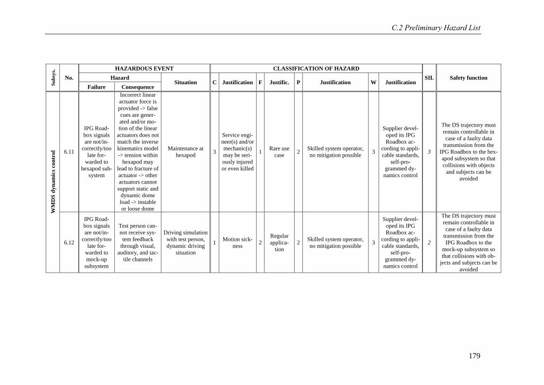
C.2 Preliminary Hazard List
179
Su
bsy
s.
No.
HAZARDOUS EVENT CLASSIFICATION OF HAZARD
SIL Safety function Hazard Situation C Justification F Justific. P Justification W Justification
Failure Consequence
WM
DS
dyn
am
ics
con
tro
l 6.11
IPG Road-
box signals
are not/in-
correctly/too
late for-
warded to
hexapod sub-
system
Incorrect linear
actuator force is
provided -> false
cues are gener-
ated and/or mo-
tion of the linear
actuators does not
match the inverse
kinematics model
-> tension within
hexapod may
lead to fracture of
actuator -> other
actuators cannot
support static and
dynamic dome
load -> instable
or loose dome
Maintenance at
hexapod 3
Service engi-
neer(s) and/or
mechanic(s)
may be seri-
ously injured
or even killed
1 Rare use
case 2
Skilled system operator,
no mitigation possible 3
Supplier devel-
oped its IPG
Roadbox ac-
cording to appli-
cable standards,
self-pro-
grammed dy-
namics control
3
The DS trajectory must
remain controllable in
case of a faulty data
transmission from the
IPG Roadbox to the hex-
apod subsystem so that
collisions with objects
and subjects can be
avoided
6.12
IPG Road-
box signals
are not/in-
correctly/too
late for-
warded to
mock-up
subsystem
Test person can-
not receive sys-
tem feedback
through visual,
auditory, and tac-
tile channels
Driving simulation
with test person,
dynamic driving
situation
1 Motion sick-
ness 2
Regular
applica-
tion
2 Skilled system operator,
no mitigation possible 3
Supplier devel-
oped its IPG
Roadbox ac-
cording to appli-
cable standards,
self-pro-
grammed dy-
namics control
2
The DS trajectory must
remain controllable in
case of a faulty data
transmission from the
IPG Roadbox to the
mock-up subsystem so
that collisions with ob-
jects and subjects can be
avoided
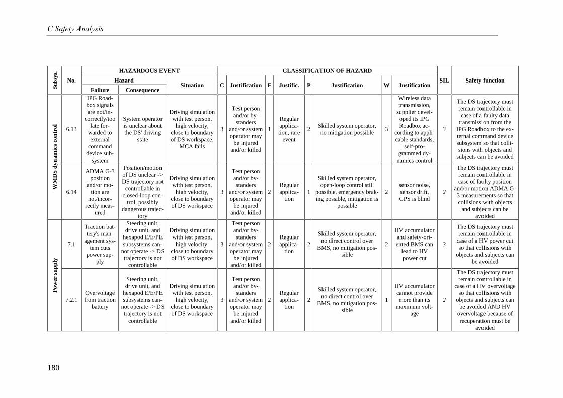
C Safety Analysis
180
Su
bsy
s.
No.
HAZARDOUS EVENT CLASSIFICATION OF HAZARD
SIL Safety function Hazard Situation C Justification F Justific. P Justification W Justification
Failure Consequence
WM
DS
dyn
am
ics
con
tro
l
6.13
IPG Road-
box signals
are not/in-
correctly/too
late for-
warded to
external
command
device sub-
system
System operator
is unclear about
the DS' driving
state
Driving simulation
with test person,
high velocity,
close to boundary
of DS workspace,
MCA fails
3
Test person
and/or by-
standers
and/or system
operator may
be injured
and/or killed
1
Regular
applica-
tion, rare
event
2 Skilled system operator,
no mitigation possible 3
Wireless data
transmission,
supplier devel-
oped its IPG
Roadbox ac-
cording to appli-
cable standards,
self-pro-
grammed dy-
namics control
3
The DS trajectory must
remain controllable in
case of a faulty data
transmission from the
IPG Roadbox to the ex-
ternal command device
subsystem so that colli-
sions with objects and
subjects can be avoided
6.14
ADMA G-3
position
and/or mo-
tion are
not/incor-
rectly meas-
ured
Position/motion
of DS unclear ->
DS trajectory not
controllable in
closed-loop con-
trol, possibly
dangerous trajec-
tory
Driving simulation
with test person,
high velocity,
close to boundary
of DS workspace
3
Test person
and/or by-
standers
and/or system
operator may
be injured
and/or killed
2
Regular
applica-
tion
1
Skilled system operator,
open-loop control still
possible, emergency brak-
ing possible, mitigation is
possible
2
sensor noise,
sensor drift,
GPS is blind
2
The DS trajectory must
remain controllable in
case of faulty position
and/or motion ADMA G-
3 measurements so that
collisions with objects
and subjects can be
avoided
Po
wer
su
pp
ly
7.1
Traction bat-
tery's man-
agement sys-
tem cuts
power sup-
ply
Steering unit,
drive unit, and
hexapod E/E/PE
subsystems can-
not operate -> DS
trajectory is not
controllable
Driving simulation
with test person,
high velocity,
close to boundary
of DS workspace
3
Test person
and/or by-
standers
and/or system
operator may
be injured
and/or killed
2
Regular
applica-
tion
2
Skilled system operator,
no direct control over
BMS, no mitigation pos-
sible
2
HV accumulator
and safety-ori-
ented BMS can
lead to HV
power cut
3
The DS trajectory must
remain controllable in
case of a HV power cut
so that collisions with
objects and subjects can
be avoided
7.2.1
Overvoltage
from traction
battery
Steering unit,
drive unit, and
hexapod E/E/PE
subsystems can-
not operate -> DS
trajectory is not
controllable
Driving simulation
with test person,
high velocity,
close to boundary
of DS workspace
3
Test person
and/or by-
standers
and/or system
operator may
be injured
and/or killed
2
Regular
applica-
tion
2
Skilled system operator,
no direct control over
BMS, no mitigation pos-
sible
1
HV accumulator
cannot provide
more than its
maximum volt-
age
2
The DS trajectory must
remain controllable in
case of a HV overvoltage
so that collisions with
objects and subjects can
be avoided AND HV
overvoltage because of
recuperation must be
avoided
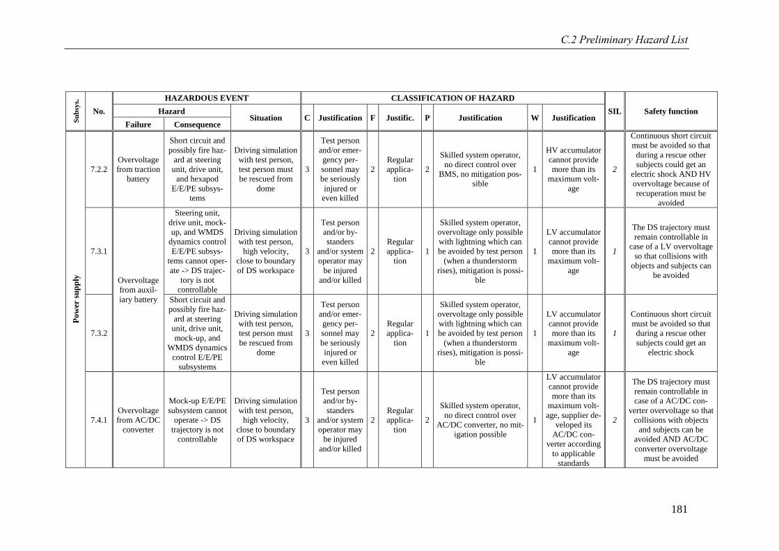
C.2 Preliminary Hazard List
181
Su
bsy
s.
No.
HAZARDOUS EVENT CLASSIFICATION OF HAZARD
SIL Safety function Hazard Situation C Justification F Justific. P Justification W Justification
Failure Consequence
Po
wer
su
pp
ly
7.2.2
Overvoltage
from traction
battery
Short circuit and
possibly fire haz-
ard at steering
unit, drive unit,
and hexapod
E/E/PE subsys-
tems
Driving simulation
with test person,
test person must
be rescued from
dome
3
Test person
and/or emer-
gency per-
sonnel may
be seriously
injured or
even killed
2
Regular
applica-
tion
2
Skilled system operator,
no direct control over
BMS, no mitigation pos-
sible
1
HV accumulator
cannot provide
more than its
maximum volt-
age
2
Continuous short circuit
must be avoided so that
during a rescue other
subjects could get an
electric shock AND HV
overvoltage because of
recuperation must be
avoided
7.3.1
Overvoltage
from auxil-
iary battery
Steering unit,
drive unit, mock-
up, and WMDS
dynamics control
E/E/PE subsys-
tems cannot oper-
ate -> DS trajec-
tory is not
controllable
Driving simulation
with test person,
high velocity,
close to boundary
of DS workspace
3
Test person
and/or by-
standers
and/or system
operator may
be injured
and/or killed
2
Regular
applica-
tion
1
Skilled system operator,
overvoltage only possible
with lightning which can
be avoided by test person
(when a thunderstorm
rises), mitigation is possi-
ble
1
LV accumulator
cannot provide
more than its
maximum volt-
age
1
The DS trajectory must
remain controllable in
case of a LV overvoltage
so that collisions with
objects and subjects can
be avoided
7.3.2
Short circuit and
possibly fire haz-
ard at steering
unit, drive unit,
mock-up, and
WMDS dynamics
control E/E/PE
subsystems
Driving simulation
with test person,
test person must
be rescued from
dome
3
Test person
and/or emer-
gency per-
sonnel may
be seriously
injured or
even killed
2
Regular
applica-
tion
1
Skilled system operator,
overvoltage only possible
with lightning which can
be avoided by test person
(when a thunderstorm
rises), mitigation is possi-
ble
1
LV accumulator
cannot provide
more than its
maximum volt-
age
1
Continuous short circuit
must be avoided so that
during a rescue other
subjects could get an
electric shock
7.4.1
Overvoltage
from AC/DC
converter
Mock-up E/E/PE
subsystem cannot
operate -> DS
trajectory is not
controllable
Driving simulation
with test person,
high velocity,
close to boundary
of DS workspace
3
Test person
and/or by-
standers
and/or system
operator may
be injured
and/or killed
2
Regular
applica-
tion
2
Skilled system operator,
no direct control over
AC/DC converter, no mit-
igation possible
1
LV accumulator
cannot provide
more than its
maximum volt-
age, supplier de-
veloped its
AC/DC con-
verter according
to applicable
standards
2
The DS trajectory must
remain controllable in
case of a AC/DC con-
verter overvoltage so that
collisions with objects
and subjects can be
avoided AND AC/DC
converter overvoltage
must be avoided
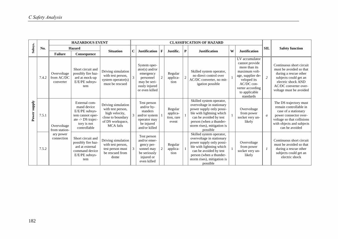
C Safety Analysis
182
Su
bsy
s.
No.
HAZARDOUS EVENT CLASSIFICATION OF HAZARD
SIL Safety function Hazard Situation C Justification F Justific. P Justification W Justification
Failure Consequence
Po
wer
su
pp
ly
7.4.2
Overvoltage
from AC/DC
converter
Short circuit and
possibly fire haz-
ard at mock-up
E/E/PE subsys-
tem
Driving simulation
with test person,
system operator(s)
must be rescued
3
System oper-
ator(s) and/or
emergency
personnel
may be seri-
ously injured
or even killed
2
Regular
applica-
tion
2
Skilled system operator,
no direct control over
AC/DC converter, no mit-
igation possible
1
LV accumulator
cannot provide
more than its
maximum volt-
age, supplier de-
veloped its
AC/DC con-
verter according
to applicable
standards
2
Continuous short circuit
must be avoided so that
during a rescue other
subjects could get an
electric shock AND
AC/DC converter over-
voltage must be avoided
7.5.1
Overvoltage
from station-
ary power
connection
External com-
mand device
E/E/PE subsys-
tem cannot oper-
ate -> DS trajec-
tory is not
controllable
Driving simulation
with test person,
high velocity,
close to boundary
of DS workspace,
MCA fails
3
Test person
and/or by-
standers
and/or system
operator may
be injured
and/or killed
1
Regular
applica-
tion, rare
event
1
Skilled system operator,
overvoltage in stationary
power supply only possi-
ble with lightning which
can be avoided by test
person (when a thunder-
storm rises), mitigation is
possible
1
Overvoltage
from power
socket very un-
likely
a
The DS trajectory must
remain controllable in
case of a stationary
power connector over-
voltage so that collisions
with objects and subjects
can be avoided
7.5.2
Short circuit and
possibly fire haz-
ard at external
command device
E/E/PE subsys-
tem
Driving simulation
with test person,
test person must
be rescued from
dome
3
Test person
and/or emer-
gency per-
sonnel may
be seriously
injured or
even killed
2
Regular
applica-
tion
1
Skilled system operator,
overvoltage in stationary
power supply only possi-
ble with lightning which
can be avoided by test
person (when a thunder-
storm rises), mitigation is
possible
1
Overvoltage
from power
socket very un-
likely
1
Continuous short circuit
must be avoided so that
during a rescue other
subjects could get an
electric shock
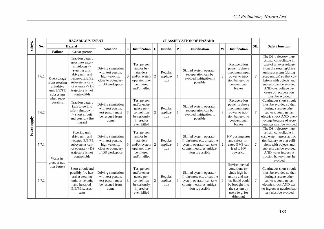
C.2 Preliminary Hazard List
183
Su
bsy
s.
No.
HAZARDOUS EVENT CLASSIFICATION OF HAZARD
SIL Safety function Hazard Situation C Justification F Justific. P Justification W Justification
Failure Consequence
Po
wer
su
pp
ly
7.6.1 Overvoltage
from steering
unit/drive
unit E/E/PE
subsystem
when recu-
perating
Traction battery
goes into safety
shutdown ->
steering unit,
drive unit, and
hexapod E/E/PE
subsystems can-
not operate -> DS
trajectory is not
controllable
Driving simulation
with test person,
high velocity,
close to boundary
of DS workspace
3
Test person
and/or by-
standers
and/or system
operator may
be injured
and/or killed
2
Regular
applica-
tion
1
Skilled system operator,
recuperation can be
avoided, mitigation is
possible
3
Recuperation
power is above
maximum input
power to trac-
tion battery, no
conventional
brakes
3
The DS trajectory must
remain controllable in
case of an overvoltage
from the steering/drive
unit subsystem (during
recuperation) so that col-
lisions with objects and
subjects can be avoided
AND overvoltage be-
cause of recuperation
must be avoided
7.6.2
Traction battery
fails to go into
safety shutdown -
> short circuit
and possibly fire
hazard
Driving simulation
with test person,
test person must
be rescued from
dome
3
Test person
and/or emer-
gency per-
sonnel may
be seriously
injured or
even killed
2
Regular
applica-
tion
1
Skilled system operator,
recuperation can be
avoided, mitigation is
possible
3
Recuperation
power is above
maximum input
power to trac-
tion battery, no
conventional
brakes
3
Continuous short circuit
must be avoided so that
during a rescue other
subjects could get an
electric shock AND over-
voltage because of recu-
peration must be avoided
7.7.1
Water in-
gress at trac-
tion battery
Steering unit,
drive unit, and
hexapod E/E/PE
subsystems can-
not operate -> DS
trajectory is not
controllable
Driving simulation
with test person,
high velocity,
close to boundary
of DS workspace
3
Test person
and/or by-
standers
and/or system
operator may
be injured
and/or killed
2
Regular
applica-
tion
1
Skilled system operator,
if rain/snow etc. arises the
system operator can take
countermeasures, mitiga-
tion is possible
2
HV accumulator
and safety-ori-
ented BMS can
lead to HV
power cut
2
The DS trajectory must
remain controllable in
case water ingress at trac-
tion battery so that colli-
sions with objects and
subjects can be avoided
AND water ingress at
traction battery must be
avoided
7.7.2
Short circuit and
possibly fire haz-
ard at steering
unit, drive unit,
and hexapod
E/E/PE subsys-
tems
Driving simulation
with test person,
test person must
be rescued from
dome
3
Test person
and/or emer-
gency per-
sonnel may
be seriously
injured or
even killed
2
Regular
applica-
tion
1
Skilled system operator,
if rain/snow etc. arises the
system operator can take
countermeasures, mitiga-
tion is possible
2
Environmental
conditions ex-
clude high hu-
midity and wa-
ter, liquid could
be brought into
the system by
users (e.g. for
drinking)
2
Continuous short circuit
must be avoided so that
during a rescue other
subjects could get an
electric shock AND wa-
ter ingress at traction bat-
tery must be avoided
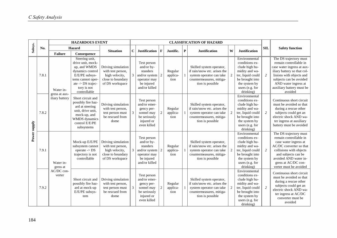
C Safety Analysis
184
Su
bsy
s.
No.
HAZARDOUS EVENT CLASSIFICATION OF HAZARD
SIL Safety function Hazard Situation C Justification F Justific. P Justification W Justification
Failure Consequence
Po
wer
su
pp
ly
7.8.1
Water in-
gress at aux-
iliary battery
Steering unit,
drive unit, mock-
up, and WMDS
dynamics control
E/E/PE subsys-
tems cannot oper-
ate -> DS trajec-
tory is not
controllable
Driving simulation
with test person,
high velocity,
close to boundary
of DS workspace
3
Test person
and/or by-
standers
and/or system
operator may
be injured
and/or killed
2
Regular
applica-
tion
1
Skilled system operator,
if rain/snow etc. arises the
system operator can take
countermeasures, mitiga-
tion is possible
2
Environmental
conditions ex-
clude high hu-
midity and wa-
ter, liquid could
be brought into
the system by
users (e.g. for
drinking)
2
The DS trajectory must
remain controllable in
case water ingress at aux-
iliary battery so that col-
lisions with objects and
subjects can be avoided
AND water ingress at
auxiliary battery must be
avoided
7.8.2
Short circuit and
possibly fire haz-
ard at steering
unit, drive unit,
mock-up, and
WMDS dynamics
control E/E/PE
subsystems
Driving simulation
with test person,
test person must
be rescued from
dome
3
Test person
and/or emer-
gency per-
sonnel may
be seriously
injured or
even killed
2
Regular
applica-
tion
1
Skilled system operator,
if rain/snow etc. arises the
system operator can take
countermeasures, mitiga-
tion is possible
2
Environmental
conditions ex-
clude high hu-
midity and wa-
ter, liquid could
be brought into
the system by
users (e.g. for
drinking)
2
Continuous short circuit
must be avoided so that
during a rescue other
subjects could get an
electric shock AND wa-
ter ingress at auxiliary
battery must be avoided
7.9.1
Water in-
gress at
AC/DC con-
verter
Mock-up E/E/PE
subsystem cannot
operate -> DS
trajectory is not
controllable
Driving simulation
with test person,
high velocity,
close to boundary
of DS workspace
3
Test person
and/or by-
standers
and/or system
operator may
be injured
and/or killed
2
Regular
applica-
tion
1
Skilled system operator,
if rain/snow etc. arises the
system operator can take
countermeasures, mitiga-
tion is possible
2
Environmental
conditions ex-
clude high hu-
midity and wa-
ter, liquid could
be brought into
the system by
users (e.g. for
drinking)
2
The DS trajectory must
remain controllable in
case water ingress at
AC/DC converter so that
collisions with objects
and subjects can be
avoided AND water in-
gress at AC/DC con-
verter must be avoided
7.9.2
Short circuit and
possibly fire haz-
ard at mock-up
E/E/PE subsys-
tem
Driving simulation
with test person,
test person must
be rescued from
dome
3
Test person
and/or emer-
gency per-
sonnel may
be seriously
injured or
even killed
2
Regular
applica-
tion
1
Skilled system operator,
if rain/snow etc. arises the
system operator can take
countermeasures, mitiga-
tion is possible
2
Environmental
conditions ex-
clude high hu-
midity and wa-
ter, liquid could
be brought into
the system by
users (e.g. for
drinking)
2
Continuous short circuit
must be avoided so that
during a rescue other
subjects could get an
electric shock AND wa-
ter ingress at AC/DC
converter must be
avoided
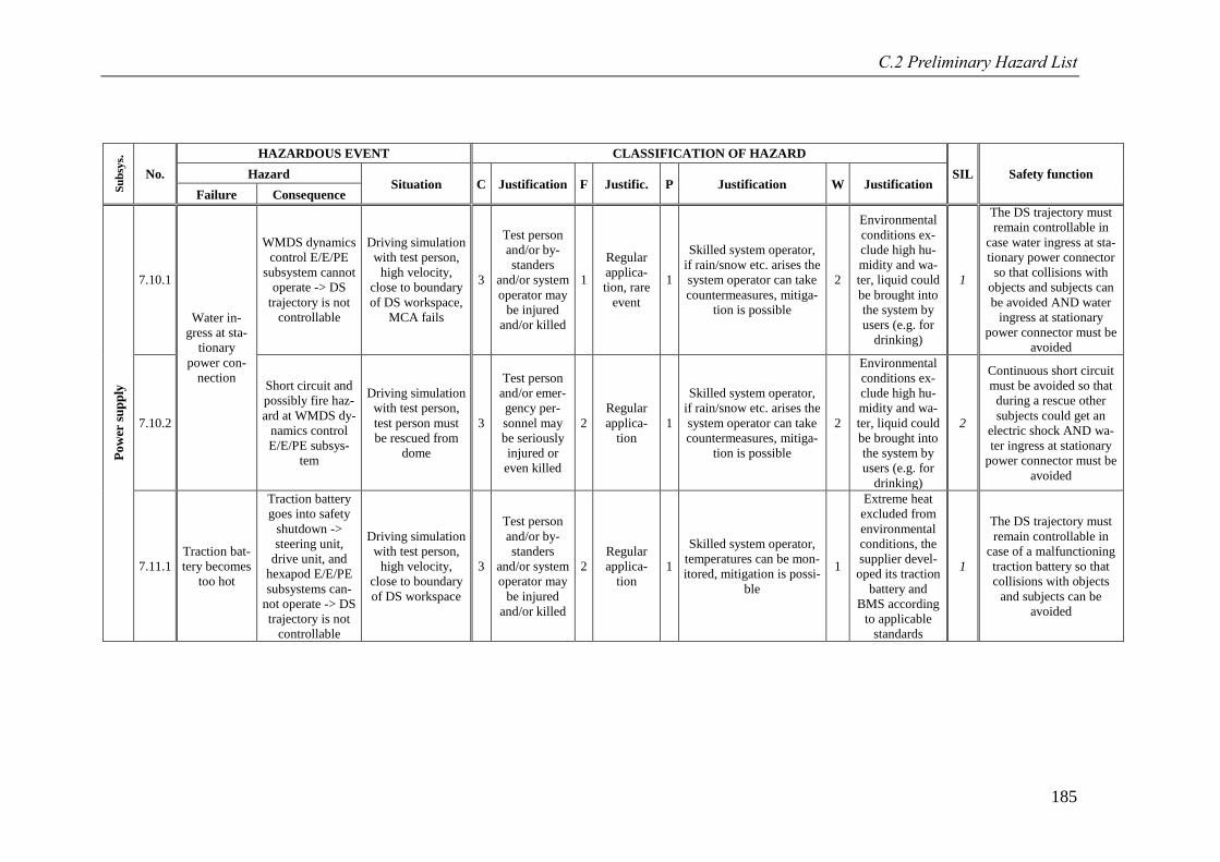
C.2 Preliminary Hazard List
185
Su
bsy
s.
No.
HAZARDOUS EVENT CLASSIFICATION OF HAZARD
SIL Safety function Hazard Situation C Justification F Justific. P Justification W Justification
Failure Consequence
Po
wer
su
pp
ly
7.10.1
Water in-
gress at sta-
tionary
power con-
nection
WMDS dynamics
control E/E/PE
subsystem cannot
operate -> DS
trajectory is not
controllable
Driving simulation
with test person,
high velocity,
close to boundary
of DS workspace,
MCA fails
3
Test person
and/or by-
standers
and/or system
operator may
be injured
and/or killed
1
Regular
applica-
tion, rare
event
1
Skilled system operator,
if rain/snow etc. arises the
system operator can take
countermeasures, mitiga-
tion is possible
2
Environmental
conditions ex-
clude high hu-
midity and wa-
ter, liquid could
be brought into
the system by
users (e.g. for
drinking)
1
The DS trajectory must
remain controllable in
case water ingress at sta-
tionary power connector
so that collisions with
objects and subjects can
be avoided AND water
ingress at stationary
power connector must be
avoided
7.10.2
Short circuit and
possibly fire haz-
ard at WMDS dy-
namics control
E/E/PE subsys-
tem
Driving simulation
with test person,
test person must
be rescued from
dome
3
Test person
and/or emer-
gency per-
sonnel may
be seriously
injured or
even killed
2
Regular
applica-
tion
1
Skilled system operator,
if rain/snow etc. arises the
system operator can take
countermeasures, mitiga-
tion is possible
2
Environmental
conditions ex-
clude high hu-
midity and wa-
ter, liquid could
be brought into
the system by
users (e.g. for
drinking)
2
Continuous short circuit
must be avoided so that
during a rescue other
subjects could get an
electric shock AND wa-
ter ingress at stationary
power connector must be
avoided
7.11.1
Traction bat-
tery becomes
too hot
Traction battery
goes into safety
shutdown ->
steering unit,
drive unit, and
hexapod E/E/PE
subsystems can-
not operate -> DS
trajectory is not
controllable
Driving simulation
with test person,
high velocity,
close to boundary
of DS workspace
3
Test person
and/or by-
standers
and/or system
operator may
be injured
and/or killed
2
Regular
applica-
tion
1
Skilled system operator,
temperatures can be mon-
itored, mitigation is possi-
ble
1
Extreme heat
excluded from
environmental
conditions, the
supplier devel-
oped its traction
battery and
BMS according
to applicable
standards
1
The DS trajectory must
remain controllable in
case of a malfunctioning
traction battery so that
collisions with objects
and subjects can be
avoided
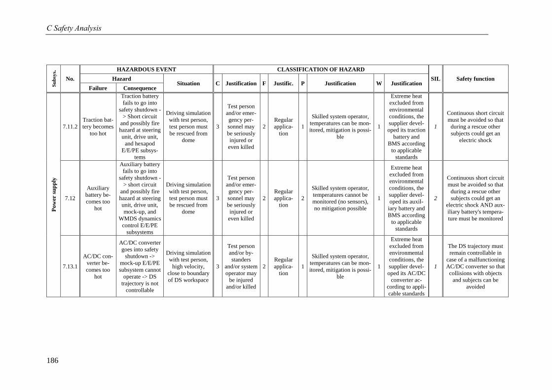
C Safety Analysis
186
Su
bsy
s.
No.
HAZARDOUS EVENT CLASSIFICATION OF HAZARD
SIL Safety function Hazard Situation C Justification F Justific. P Justification W Justification
Failure Consequence
Po
wer
su
pp
ly
7.11.2
Traction bat-
tery becomes
too hot
Traction battery
fails to go into
safety shutdown -
> Short circuit
and possibly fire
hazard at steering
unit, drive unit,
and hexapod
E/E/PE subsys-
tems
Driving simulation
with test person,
test person must
be rescued from
dome
3
Test person
and/or emer-
gency per-
sonnel may
be seriously
injured or
even killed
2
Regular
applica-
tion
1
Skilled system operator,
temperatures can be mon-
itored, mitigation is possi-
ble
1
Extreme heat
excluded from
environmental
conditions, the
supplier devel-
oped its traction
battery and
BMS according
to applicable
standards
1
Continuous short circuit
must be avoided so that
during a rescue other
subjects could get an
electric shock
7.12
Auxiliary
battery be-
comes too
hot
Auxiliary battery
fails to go into
safety shutdown -
> short circuit
and possibly fire
hazard at steering
unit, drive unit,
mock-up, and
WMDS dynamics
control E/E/PE
subsystems
Driving simulation
with test person,
test person must
be rescued from
dome
3
Test person
and/or emer-
gency per-
sonnel may
be seriously
injured or
even killed
2
Regular
applica-
tion
2
Skilled system operator,
temperatures cannot be
monitored (no sensors),
no mitigation possible
1
Extreme heat
excluded from
environmental
conditions, the
supplier devel-
oped its auxil-
iary battery and
BMS according
to applicable
standards
2
Continuous short circuit
must be avoided so that
during a rescue other
subjects could get an
electric shock AND aux-
iliary battery's tempera-
ture must be monitored
7.13.1
AC/DC con-
verter be-
comes too
hot
AC/DC converter
goes into safety
shutdown ->
mock-up E/E/PE
subsystem cannot
operate -> DS
trajectory is not
controllable
Driving simulation
with test person,
high velocity,
close to boundary
of DS workspace
3
Test person
and/or by-
standers
and/or system
operator may
be injured
and/or killed
2
Regular
applica-
tion
1
Skilled system operator,
temperatures can be mon-
itored, mitigation is possi-
ble
1
Extreme heat
excluded from
environmental
conditions, the
supplier devel-
oped its AC/DC
converter ac-
cording to appli-
cable standards
1
The DS trajectory must
remain controllable in
case of a malfunctioning
AC/DC converter so that
collisions with objects
and subjects can be
avoided
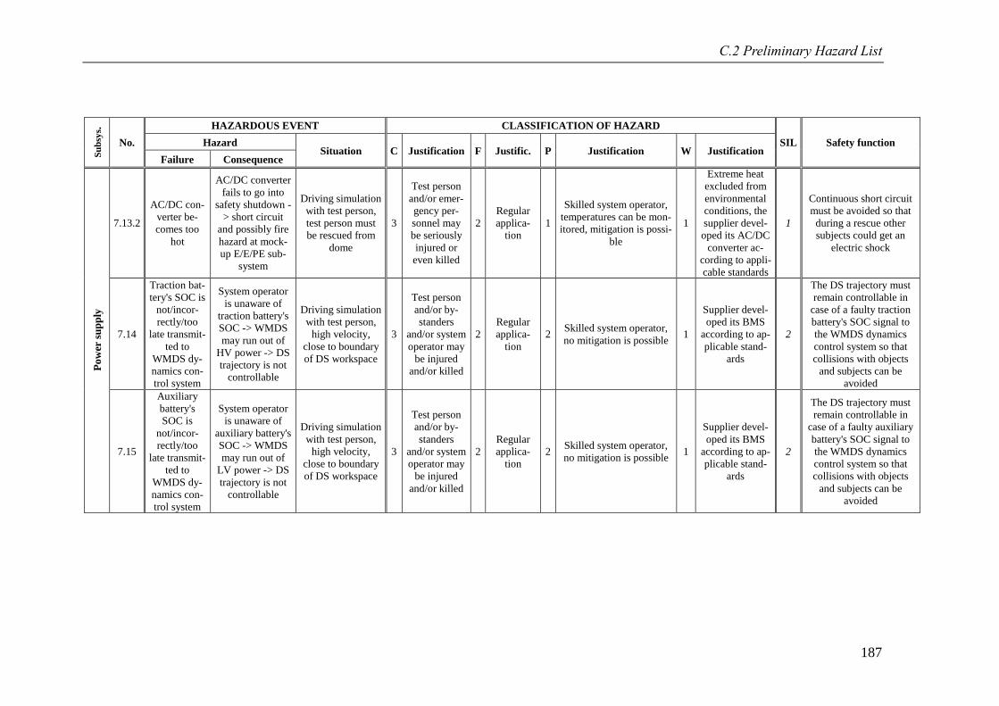
C.2 Preliminary Hazard List
187
Su
bsy
s.
No.
HAZARDOUS EVENT CLASSIFICATION OF HAZARD
SIL Safety function Hazard Situation C Justification F Justific. P Justification W Justification
Failure Consequence
Po
wer
su
pp
ly
7.13.2
AC/DC con-
verter be-
comes too
hot
AC/DC converter
fails to go into
safety shutdown -
> short circuit
and possibly fire
hazard at mock-
up E/E/PE sub-
system
Driving simulation
with test person,
test person must
be rescued from
dome
3
Test person
and/or emer-
gency per-
sonnel may
be seriously
injured or
even killed
2
Regular
applica-
tion
1
Skilled system operator,
temperatures can be mon-
itored, mitigation is possi-
ble
1
Extreme heat
excluded from
environmental
conditions, the
supplier devel-
oped its AC/DC
converter ac-
cording to appli-
cable standards
1
Continuous short circuit
must be avoided so that
during a rescue other
subjects could get an
electric shock
7.14
Traction bat-
tery's SOC is
not/incor-
rectly/too
late transmit-
ted to
WMDS dy-
namics con-
trol system
System operator
is unaware of
traction battery's
SOC -> WMDS
may run out of
HV power -> DS
trajectory is not
controllable
Driving simulation
with test person,
high velocity,
close to boundary
of DS workspace
3
Test person
and/or by-
standers
and/or system
operator may
be injured
and/or killed
2
Regular
applica-
tion
2 Skilled system operator,
no mitigation is possible 1
Supplier devel-
oped its BMS
according to ap-
plicable stand-
ards
2
The DS trajectory must
remain controllable in
case of a faulty traction
battery's SOC signal to
the WMDS dynamics
control system so that
collisions with objects
and subjects can be
avoided
7.15
Auxiliary
battery's
SOC is
not/incor-
rectly/too
late transmit-
ted to
WMDS dy-
namics con-
trol system
System operator
is unaware of
auxiliary battery's
SOC -> WMDS
may run out of
LV power -> DS
trajectory is not
controllable
Driving simulation
with test person,
high velocity,
close to boundary
of DS workspace
3
Test person
and/or by-
standers
and/or system
operator may
be injured
and/or killed
2
Regular
applica-
tion
2 Skilled system operator,
no mitigation is possible 1
Supplier devel-
oped its BMS
according to ap-
plicable stand-
ards
2
The DS trajectory must
remain controllable in
case of a faulty auxiliary
battery's SOC signal to
the WMDS dynamics
control system so that
collisions with objects
and subjects can be
avoided

188
C.3 Revised Hazard List
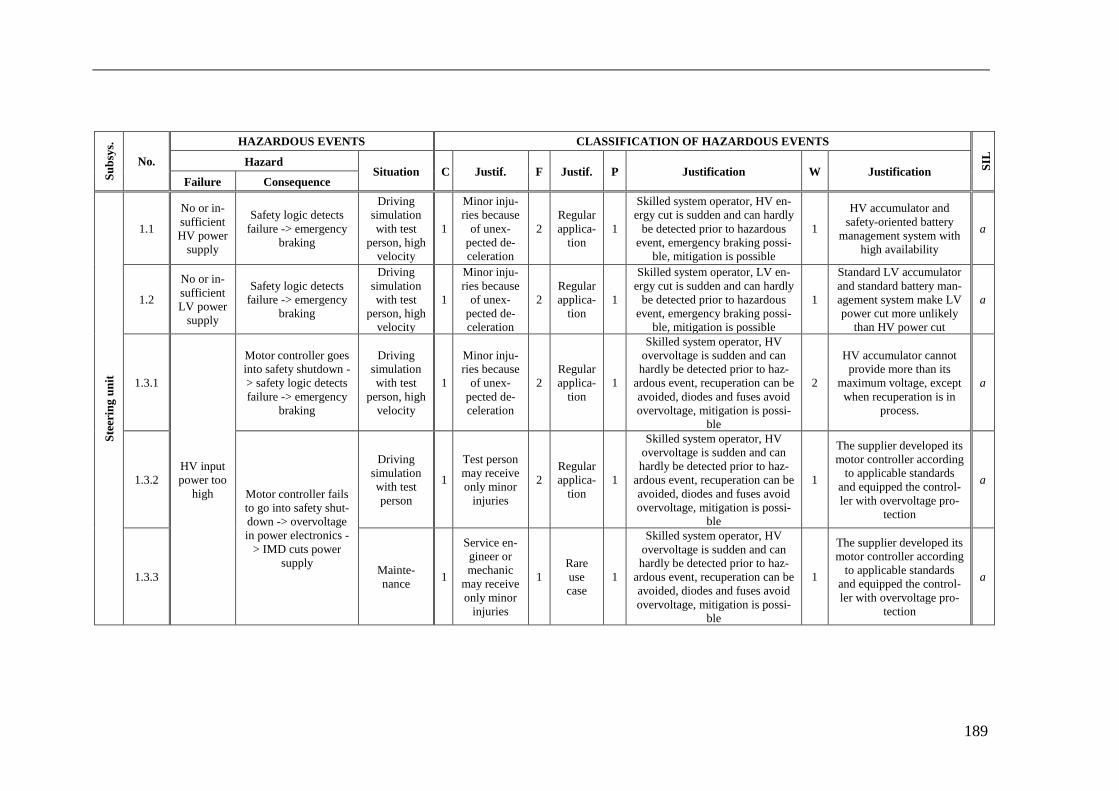
189
Su
bsy
s.
No.
HAZARDOUS EVENTS CLASSIFICATION OF HAZARDOUS EVENTS
SIL
Hazard Situation C Justif. F Justif. P Justification W Justification
Failure Consequence
Ste
erin
g u
nit
1.1
No or in-
sufficient
HV power
supply
Safety logic detects
failure -> emergency
braking
Driving
simulation
with test
person, high
velocity
1
Minor inju-
ries because
of unex-
pected de-
celeration
2
Regular
applica-
tion
1
Skilled system operator, HV en-
ergy cut is sudden and can hardly
be detected prior to hazardous
event, emergency braking possi-
ble, mitigation is possible
1
HV accumulator and
safety-oriented battery
management system with
high availability
a
1.2
No or in-
sufficient
LV power
supply
Safety logic detects
failure -> emergency
braking
Driving
simulation
with test
person, high
velocity
1
Minor inju-
ries because
of unex-
pected de-
celeration
2
Regular
applica-
tion
1
Skilled system operator, LV en-
ergy cut is sudden and can hardly
be detected prior to hazardous
event, emergency braking possi-
ble, mitigation is possible
1
Standard LV accumulator
and standard battery man-
agement system make LV
power cut more unlikely
than HV power cut
a
1.3.1
HV input
power too
high
Motor controller goes
into safety shutdown -
> safety logic detects
failure -> emergency
braking
Driving
simulation
with test
person, high
velocity
1
Minor inju-
ries because
of unex-
pected de-
celeration
2
Regular
applica-
tion
1
Skilled system operator, HV
overvoltage is sudden and can
hardly be detected prior to haz-
ardous event, recuperation can be
avoided, diodes and fuses avoid
overvoltage, mitigation is possi-
ble
2
HV accumulator cannot
provide more than its
maximum voltage, except
when recuperation is in
process.
a
1.3.2
Motor controller fails
to go into safety shut-
down -> overvoltage
in power electronics -
> IMD cuts power
supply
Driving
simulation
with test
person
1
Test person
may receive
only minor
injuries
2
Regular
applica-
tion
1
Skilled system operator, HV
overvoltage is sudden and can
hardly be detected prior to haz-
ardous event, recuperation can be
avoided, diodes and fuses avoid
overvoltage, mitigation is possi-
ble
1
The supplier developed its
motor controller according
to applicable standards
and equipped the control-
ler with overvoltage pro-
tection
a
1.3.3 Mainte-
nance 1
Service en-
gineer or
mechanic
may receive
only minor
injuries
1
Rare
use
case
1
Skilled system operator, HV
overvoltage is sudden and can
hardly be detected prior to haz-
ardous event, recuperation can be
avoided, diodes and fuses avoid
overvoltage, mitigation is possi-
ble
1
The supplier developed its
motor controller according
to applicable standards
and equipped the control-
ler with overvoltage pro-
tection
a
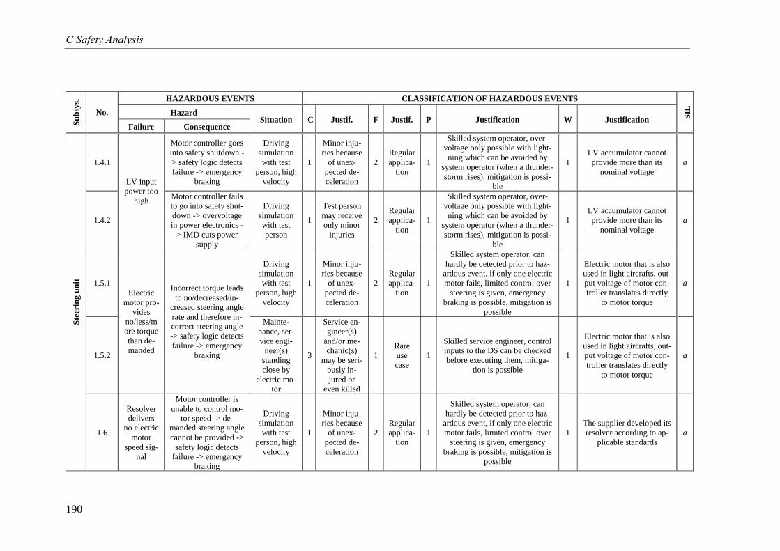
C Safety Analysis
190
Su
bsy
s.
No.
HAZARDOUS EVENTS CLASSIFICATION OF HAZARDOUS EVENTS
SIL
Hazard Situation C Justif. F Justif. P Justification W Justification
Failure Consequence
Ste
erin
g u
nit
1.4.1
LV input
power too
high
Motor controller goes
into safety shutdown -
> safety logic detects
failure -> emergency
braking
Driving
simulation
with test
person, high
velocity
1
Minor inju-
ries because
of unex-
pected de-
celeration
2
Regular
applica-
tion
1
Skilled system operator, over-
voltage only possible with light-
ning which can be avoided by
system operator (when a thunder-
storm rises), mitigation is possi-
ble
1
LV accumulator cannot
provide more than its
nominal voltage
a
1.4.2
Motor controller fails
to go into safety shut-
down -> overvoltage
in power electronics -
> IMD cuts power
supply
Driving
simulation
with test
person
1
Test person
may receive
only minor
injuries
2
Regular
applica-
tion
1
Skilled system operator, over-
voltage only possible with light-
ning which can be avoided by
system operator (when a thunder-
storm rises), mitigation is possi-
ble
1
LV accumulator cannot
provide more than its
nominal voltage
a
1.5.1
Electric
motor pro-
vides
no/less/m
ore torque
than de-
manded
Incorrect torque leads
to no/decreased/in-
creased steering angle
rate and therefore in-
correct steering angle
-> safety logic detects
failure -> emergency
braking
Driving
simulation
with test
person, high
velocity
1
Minor inju-
ries because
of unex-
pected de-
celeration
2
Regular
applica-
tion
1
Skilled system operator, can
hardly be detected prior to haz-
ardous event, if only one electric
motor fails, limited control over
steering is given, emergency
braking is possible, mitigation is
possible
1
Electric motor that is also
used in light aircrafts, out-
put voltage of motor con-
troller translates directly
to motor torque
a
1.5.2
Mainte-
nance, ser-
vice engi-
neer(s)
standing
close by
electric mo-
tor
3
Service en-
gineer(s)
and/or me-
chanic(s)
may be seri-
ously in-
jured or
even killed
1
Rare
use
case
1
Skilled service engineer, control
inputs to the DS can be checked
before executing them, mitiga-
tion is possible
1
Electric motor that is also
used in light aircrafts, out-
put voltage of motor con-
troller translates directly
to motor torque
a
1.6
Resolver
delivers
no electric
motor
speed sig-
nal
Motor controller is
unable to control mo-
tor speed -> de-
manded steering angle
cannot be provided ->
safety logic detects
failure -> emergency
braking
Driving
simulation
with test
person, high
velocity
1
Minor inju-
ries because
of unex-
pected de-
celeration
2
Regular
applica-
tion
1
Skilled system operator, can
hardly be detected prior to haz-
ardous event, if only one electric
motor fails, limited control over
steering is given, emergency
braking is possible, mitigation is
possible
1
The supplier developed its
resolver according to ap-
plicable standards
a
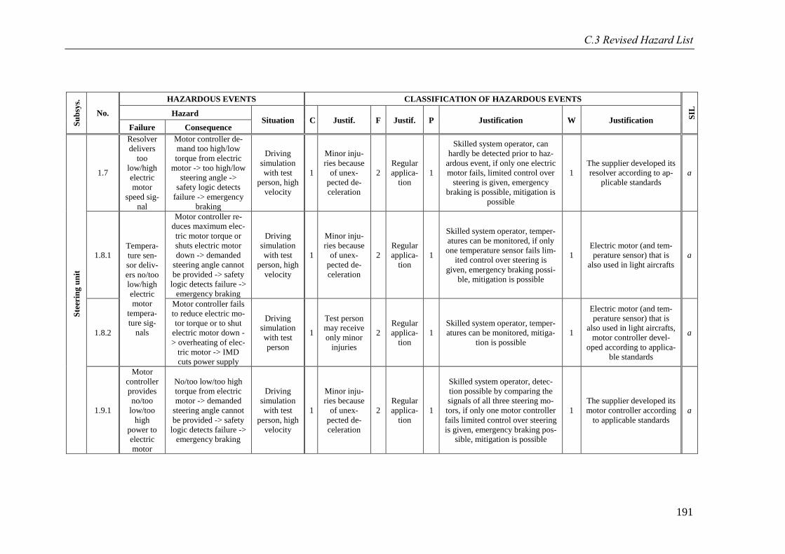
C.3 Revised Hazard List
191
Su
bsy
s.
No.
HAZARDOUS EVENTS CLASSIFICATION OF HAZARDOUS EVENTS
SIL
Hazard Situation C Justif. F Justif. P Justification W Justification
Failure Consequence
Ste
erin
g u
nit
1.7
Resolver
delivers
too
low/high
electric
motor
speed sig-
nal
Motor controller de-
mand too high/low
torque from electric
motor -> too high/low
steering angle ->
safety logic detects
failure -> emergency
braking
Driving
simulation
with test
person, high
velocity
1
Minor inju-
ries because
of unex-
pected de-
celeration
2
Regular
applica-
tion
1
Skilled system operator, can
hardly be detected prior to haz-
ardous event, if only one electric
motor fails, limited control over
steering is given, emergency
braking is possible, mitigation is
possible
1
The supplier developed its
resolver according to ap-
plicable standards
a
1.8.1 Tempera-
ture sen-
sor deliv-
ers no/too
low/high
electric
motor
tempera-
ture sig-
nals
Motor controller re-
duces maximum elec-
tric motor torque or
shuts electric motor
down -> demanded
steering angle cannot
be provided -> safety
logic detects failure ->
emergency braking
Driving
simulation
with test
person, high
velocity
1
Minor inju-
ries because
of unex-
pected de-
celeration
2
Regular
applica-
tion
1
Skilled system operator, temper-
atures can be monitored, if only
one temperature sensor fails lim-
ited control over steering is
given, emergency braking possi-
ble, mitigation is possible
1
Electric motor (and tem-
perature sensor) that is
also used in light aircrafts
a
1.8.2
Motor controller fails
to reduce electric mo-
tor torque or to shut
electric motor down -
> overheating of elec-
tric motor -> IMD
cuts power supply
Driving
simulation
with test
person
1
Test person
may receive
only minor
injuries
2
Regular
applica-
tion
1
Skilled system operator, temper-
atures can be monitored, mitiga-
tion is possible
1
Electric motor (and tem-
perature sensor) that is
also used in light aircrafts,
motor controller devel-
oped according to applica-
ble standards
a
1.9.1
Motor
controller
provides
no/too
low/too
high
power to
electric
motor
No/too low/too high
torque from electric
motor -> demanded
steering angle cannot
be provided -> safety
logic detects failure ->
emergency braking
Driving
simulation
with test
person, high
velocity
1
Minor inju-
ries because
of unex-
pected de-
celeration
2
Regular
applica-
tion
1
Skilled system operator, detec-
tion possible by comparing the
signals of all three steering mo-
tors, if only one motor controller
fails limited control over steering
is given, emergency braking pos-
sible, mitigation is possible
1
The supplier developed its
motor controller according
to applicable standards
a
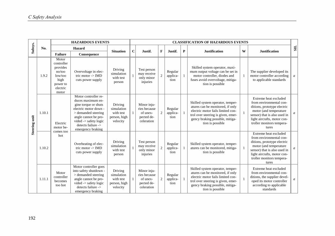
C Safety Analysis
192
Su
bsy
s.
No.
HAZARDOUS EVENTS CLASSIFICATION OF HAZARDOUS EVENTS
SIL
Hazard Situation C Justif. F Justif. P Justification W Justification
Failure Consequence
Ste
erin
g u
nit
1.9.2
Motor
controller
provides
no/too
low/too
high
power to
electric
motor
Overvoltage in elec-
tric motor -> IMD
cuts power supply
Driving
simulation
with test
person
1
Test person
may receive
only minor
injuries
2
Regular
applica-
tion
1
Skilled system operator, maxi-
mum output voltage can be set in
motor controller, diodes and
fuses avoid overvoltage, mitiga-
tion is possible
1
The supplier developed its
motor controller according
to applicable standards
a
1.10.1
Electric
motor be-
comes too
hot
Motor controller re-
duces maximum en-
gine torque or shuts
electric motor down -
> demanded steering
angle cannot be pro-
vided -> safety logic
detects failure ->
emergency braking
Driving
simulation
with test
person, high
velocity
1
Minor inju-
ries because
of unex-
pected de-
celeration
2
Regular
applica-
tion
1
Skilled system operator, temper-
atures can be monitored, if only
electric motor fails limited con-
trol over steering is given, emer-
gency braking possible, mitiga-
tion is possible
1
Extreme heat excluded
from environmental con-
ditions, prototype electric
motor (and temperature
sensor) that is also used in
light aircrafts, motor con-
troller monitors tempera-
tures
a
1.10.2
Overheating of elec-
tric motor -> IMD
cuts power supply
Driving
simulation
with test
person
1
Test person
may receive
only minor
injuries
2
Regular
applica-
tion
1
Skilled system operator, temper-
atures can be monitored, mitiga-
tion is possible
1
Extreme heat excluded
from environmental con-
ditions, prototype electric
motor (and temperature
sensor) that is also used in
light aircrafts, motor con-
troller monitors tempera-
tures
a
1.11.1
Motor
controller
becomes
too hot
Motor controller goes
into safety shutdown -
> demanded steering
angle cannot be pro-
vided -> safety logic
detects failure ->
emergency braking
Driving
simulation
with test
person, high
velocity
1
Minor inju-
ries because
of unex-
pected de-
celeration
2
Regular
applica-
tion
1
Skilled system operator, temper-
atures can be monitored, if only
electric motor fails limited con-
trol over steering is given, emer-
gency braking possible, mitiga-
tion is possible
1
Extreme heat excluded
from environmental con-
ditions, the supplier devel-
oped its motor controller
according to applicable
standards
a
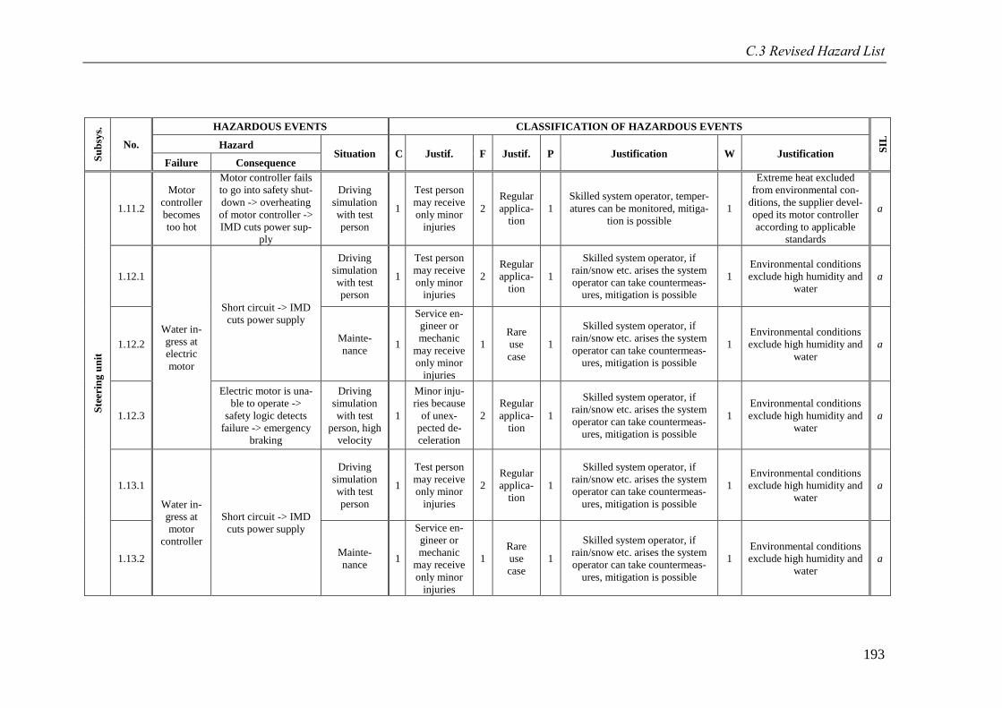
C.3 Revised Hazard List
193
Su
bsy
s.
No.
HAZARDOUS EVENTS CLASSIFICATION OF HAZARDOUS EVENTS
SIL
Hazard Situation C Justif. F Justif. P Justification W Justification
Failure Consequence
Ste
erin
g u
nit
1.11.2
Motor
controller
becomes
too hot
Motor controller fails
to go into safety shut-
down -> overheating
of motor controller ->
IMD cuts power sup-
ply
Driving
simulation
with test
person
1
Test person
may receive
only minor
injuries
2
Regular
applica-
tion
1
Skilled system operator, temper-
atures can be monitored, mitiga-
tion is possible
1
Extreme heat excluded
from environmental con-
ditions, the supplier devel-
oped its motor controller
according to applicable
standards
a
1.12.1
Water in-
gress at
electric
motor
Short circuit -> IMD
cuts power supply
Driving
simulation
with test
person
1
Test person
may receive
only minor
injuries
2
Regular
applica-
tion
1
Skilled system operator, if
rain/snow etc. arises the system
operator can take countermeas-
ures, mitigation is possible
1
Environmental conditions
exclude high humidity and
water
a
1.12.2 Mainte-
nance 1
Service en-
gineer or
mechanic
may receive
only minor
injuries
1
Rare
use
case
1
Skilled system operator, if
rain/snow etc. arises the system
operator can take countermeas-
ures, mitigation is possible
1
Environmental conditions
exclude high humidity and
water
a
1.12.3
Electric motor is una-
ble to operate ->
safety logic detects
failure -> emergency
braking
Driving
simulation
with test
person, high
velocity
1
Minor inju-
ries because
of unex-
pected de-
celeration
2
Regular
applica-
tion
1
Skilled system operator, if
rain/snow etc. arises the system
operator can take countermeas-
ures, mitigation is possible
1
Environmental conditions
exclude high humidity and
water
a
1.13.1
Water in-
gress at
motor
controller
Short circuit -> IMD
cuts power supply
Driving
simulation
with test
person
1
Test person
may receive
only minor
injuries
2
Regular
applica-
tion
1
Skilled system operator, if
rain/snow etc. arises the system
operator can take countermeas-
ures, mitigation is possible
1
Environmental conditions
exclude high humidity and
water
a
1.13.2 Mainte-
nance 1
Service en-
gineer or
mechanic
may receive
only minor
injuries
1
Rare
use
case
1
Skilled system operator, if
rain/snow etc. arises the system
operator can take countermeas-
ures, mitigation is possible
1
Environmental conditions
exclude high humidity and
water
a
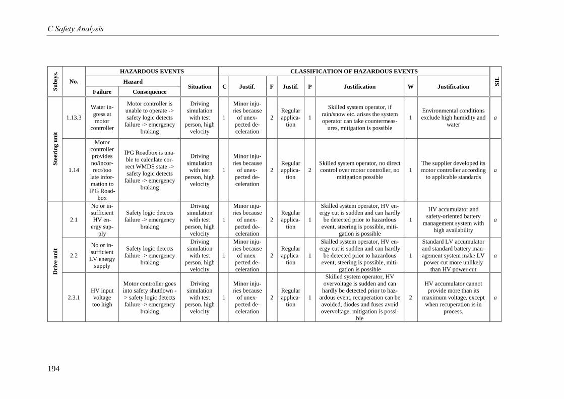
C Safety Analysis
194
Su
bsy
s.
No.
HAZARDOUS EVENTS CLASSIFICATION OF HAZARDOUS EVENTS
SIL
Hazard Situation C Justif. F Justif. P Justification W Justification
Failure Consequence
Ste
erin
g u
nit
1.13.3
Water in-
gress at
motor
controller
Motor controller is
unable to operate ->
safety logic detects
failure -> emergency
braking
Driving
simulation
with test
person, high
velocity
1
Minor inju-
ries because
of unex-
pected de-
celeration
2
Regular
applica-
tion
1
Skilled system operator, if
rain/snow etc. arises the system
operator can take countermeas-
ures, mitigation is possible
1
Environmental conditions
exclude high humidity and
water
a
1.14
Motor
controller
provides
no/incor-
rect/too
late infor-
mation to
IPG Road-
box
IPG Roadbox is una-
ble to calculate cor-
rect WMDS state ->
safety logic detects
failure -> emergency
braking
Driving
simulation
with test
person, high
velocity
1
Minor inju-
ries because
of unex-
pected de-
celeration
2
Regular
applica-
tion
2
Skilled system operator, no direct
control over motor controller, no
mitigation possible
1
The supplier developed its
motor controller according
to applicable standards
a
Dri
ve
un
it
2.1
No or in-
sufficient
HV en-
ergy sup-
ply
Safety logic detects
failure -> emergency
braking
Driving
simulation
with test
person, high
velocity
1
Minor inju-
ries because
of unex-
pected de-
celeration
2
Regular
applica-
tion
1
Skilled system operator, HV en-
ergy cut is sudden and can hardly
be detected prior to hazardous
event, steering is possible, miti-
gation is possible
1
HV accumulator and
safety-oriented battery
management system with
high availability
a
2.2
No or in-
sufficient
LV energy
supply
Safety logic detects
failure -> emergency
braking
Driving
simulation
with test
person, high
velocity
1
Minor inju-
ries because
of unex-
pected de-
celeration
2
Regular
applica-
tion
1
Skilled system operator, HV en-
ergy cut is sudden and can hardly
be detected prior to hazardous
event, steering is possible, miti-
gation is possible
1
Standard LV accumulator
and standard battery man-
agement system make LV
power cut more unlikely
than HV power cut
a
2.3.1
HV input
voltage
too high
Motor controller goes
into safety shutdown -
> safety logic detects
failure -> emergency
braking
Driving
simulation
with test
person, high
velocity
1
Minor inju-
ries because
of unex-
pected de-
celeration
2
Regular
applica-
tion
1
Skilled system operator, HV
overvoltage is sudden and can
hardly be detected prior to haz-
ardous event, recuperation can be
avoided, diodes and fuses avoid
overvoltage, mitigation is possi-
ble
2
HV accumulator cannot
provide more than its
maximum voltage, except
when recuperation is in
process.
a
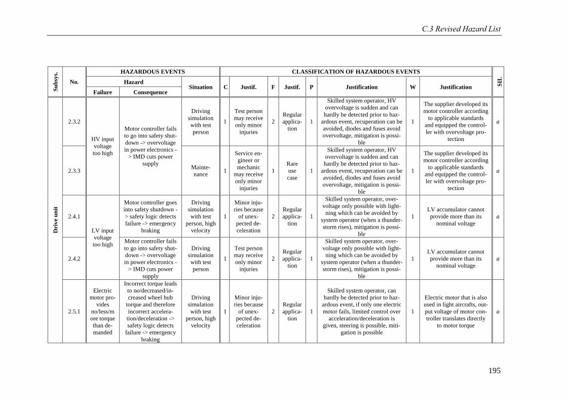
C.3 Revised Hazard List
195
Su
bsy
s.
No.
HAZARDOUS EVENTS CLASSIFICATION OF HAZARDOUS EVENTS
SIL
Hazard Situation C Justif. F Justif. P Justification W Justification
Failure Consequence
Dri
ve
un
it
2.3.2
HV input
voltage
too high
Motor controller fails
to go into safety shut-
down -> overvoltage
in power electronics -
> IMD cuts power
supply
Driving
simulation
with test
person
1
Test person
may receive
only minor
injuries
2
Regular
applica-
tion
1
Skilled system operator, HV
overvoltage is sudden and can
hardly be detected prior to haz-
ardous event, recuperation can be
avoided, diodes and fuses avoid
overvoltage, mitigation is possi-
ble
1
The supplier developed its
motor controller according
to applicable standards
and equipped the control-
ler with overvoltage pro-
tection
a
2.3.3 Mainte-
nance 1
Service en-
gineer or
mechanic
may receive
only minor
injuries
1
Rare
use
case
1
Skilled system operator, HV
overvoltage is sudden and can
hardly be detected prior to haz-
ardous event, recuperation can be
avoided, diodes and fuses avoid
overvoltage, mitigation is possi-
ble
1
The supplier developed its
motor controller according
to applicable standards
and equipped the control-
ler with overvoltage pro-
tection
a
2.4.1
LV input
voltage
too high
Motor controller goes
into safety shutdown -
> safety logic detects
failure -> emergency
braking
Driving
simulation
with test
person, high
velocity
1
Minor inju-
ries because
of unex-
pected de-
celeration
2
Regular
applica-
tion
1
Skilled system operator, over-
voltage only possible with light-
ning which can be avoided by
system operator (when a thunder-
storm rises), mitigation is possi-
ble
1
LV accumulator cannot
provide more than its
nominal voltage
a
2.4.2
Motor controller fails
to go into safety shut-
down -> overvoltage
in power electronics -
> IMD cuts power
supply
Driving
simulation
with test
person
1
Test person
may receive
only minor
injuries
2
Regular
applica-
tion
1
Skilled system operator, over-
voltage only possible with light-
ning which can be avoided by
system operator (when a thunder-
storm rises), mitigation is possi-
ble
1
LV accumulator cannot
provide more than its
nominal voltage
a
2.5.1
Electric
motor pro-
vides
no/less/m
ore torque
than de-
manded
Incorrect torque leads
to no/decreased/in-
creased wheel hub
torque and therefore
incorrect accelera-
tion/deceleration ->
safety logic detects
failure -> emergency
braking
Driving
simulation
with test
person, high
velocity
1
Minor inju-
ries because
of unex-
pected de-
celeration
2
Regular
applica-
tion
1
Skilled system operator, can
hardly be detected prior to haz-
ardous event, if only one electric
motor fails, limited control over
acceleration/deceleration is
given, steering is possible, miti-
gation is possible
1
Electric motor that is also
used in light aircrafts, out-
put voltage of motor con-
troller translates directly
to motor torque
a
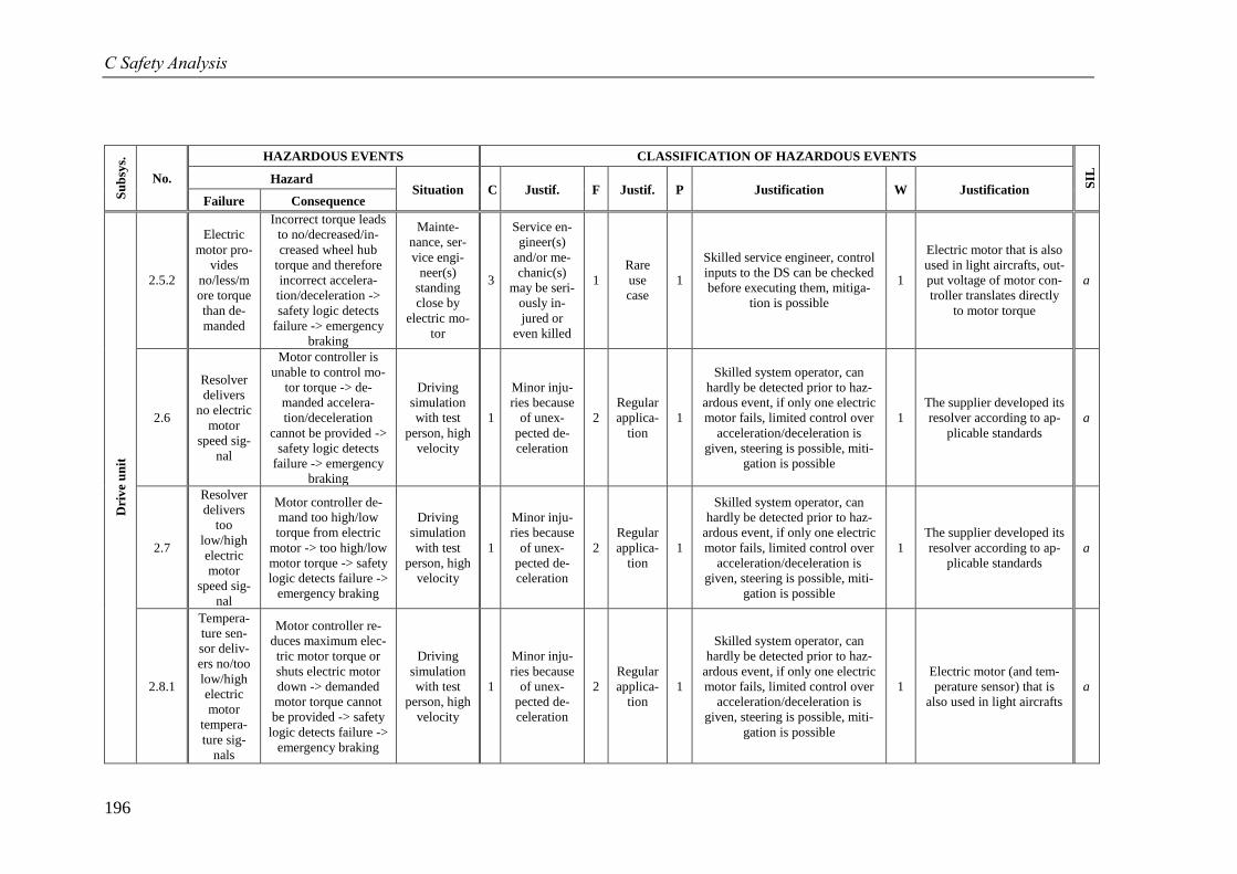
C Safety Analysis
196
Su
bsy
s.
No.
HAZARDOUS EVENTS CLASSIFICATION OF HAZARDOUS EVENTS
SIL
Hazard Situation C Justif. F Justif. P Justification W Justification
Failure Consequence
Dri
ve
un
it
2.5.2
Electric
motor pro-
vides
no/less/m
ore torque
than de-
manded
Incorrect torque leads
to no/decreased/in-
creased wheel hub
torque and therefore
incorrect accelera-
tion/deceleration ->
safety logic detects
failure -> emergency
braking
Mainte-
nance, ser-
vice engi-
neer(s)
standing
close by
electric mo-
tor
3
Service en-
gineer(s)
and/or me-
chanic(s)
may be seri-
ously in-
jured or
even killed
1
Rare
use
case
1
Skilled service engineer, control
inputs to the DS can be checked
before executing them, mitiga-
tion is possible
1
Electric motor that is also
used in light aircrafts, out-
put voltage of motor con-
troller translates directly
to motor torque
a
2.6
Resolver
delivers
no electric
motor
speed sig-
nal
Motor controller is
unable to control mo-
tor torque -> de-
manded accelera-
tion/deceleration
cannot be provided ->
safety logic detects
failure -> emergency
braking
Driving
simulation
with test
person, high
velocity
1
Minor inju-
ries because
of unex-
pected de-
celeration
2
Regular
applica-
tion
1
Skilled system operator, can
hardly be detected prior to haz-
ardous event, if only one electric
motor fails, limited control over
acceleration/deceleration is
given, steering is possible, miti-
gation is possible
1
The supplier developed its
resolver according to ap-
plicable standards
a
2.7
Resolver
delivers
too
low/high
electric
motor
speed sig-
nal
Motor controller de-
mand too high/low
torque from electric
motor -> too high/low
motor torque -> safety
logic detects failure ->
emergency braking
Driving
simulation
with test
person, high
velocity
1
Minor inju-
ries because
of unex-
pected de-
celeration
2
Regular
applica-
tion
1
Skilled system operator, can
hardly be detected prior to haz-
ardous event, if only one electric
motor fails, limited control over
acceleration/deceleration is
given, steering is possible, miti-
gation is possible
1
The supplier developed its
resolver according to ap-
plicable standards
a
2.8.1
Tempera-
ture sen-
sor deliv-
ers no/too
low/high
electric
motor
tempera-
ture sig-
nals
Motor controller re-
duces maximum elec-
tric motor torque or
shuts electric motor
down -> demanded
motor torque cannot
be provided -> safety
logic detects failure ->
emergency braking
Driving
simulation
with test
person, high
velocity
1
Minor inju-
ries because
of unex-
pected de-
celeration
2
Regular
applica-
tion
1
Skilled system operator, can
hardly be detected prior to haz-
ardous event, if only one electric
motor fails, limited control over
acceleration/deceleration is
given, steering is possible, miti-
gation is possible
1
Electric motor (and tem-
perature sensor) that is
also used in light aircrafts
a
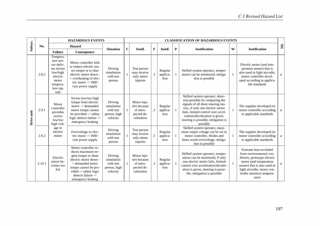
C.3 Revised Hazard List
197
Su
bsy
s.
No.
HAZARDOUS EVENTS CLASSIFICATION OF HAZARDOUS EVENTS
SIL
Hazard Situation C Justif. F Justif. P Justification W Justification
Failure Consequence
Dri
ve
un
it
2.8.2
Tempera-
ture sen-
sor deliv-
ers no/too
low/high
electric
motor
tempera-
ture sig-
nals
Motor controller fails
to reduce electric mo-
tor torque or to shut
electric motor down -
> overheating of elec-
tric motor -> IMD
cuts power supply
Driving
simulation
with test
person
1
Test person
may receive
only minor
injuries
2
Regular
applica-
tion
1
Skilled system operator, temper-
atures can be monitored, mitiga-
tion is possible
1
Electric motor (and tem-
perature sensor) that is
also used in light aircrafts,
motor controller devel-
oped according to applica-
ble standards
a
2.9.1
Motor
controller
provides
no/too
low/too
high volt-
age to
electric
motor
No/too low/too high
torque from electric
motor -> demanded
motor torque cannot
be provided -> safety
logic detects failure ->
emergency braking
Driving
simulation
with test
person, high
velocity
1
Minor inju-
ries because
of unex-
pected de-
celeration
2
Regular
applica-
tion
1
Skilled system operator, detec-
tion possible by comparing the
signals of all three steering mo-
tors, if only one electric motor
fails, limited control over accel-
eration/deceleration is given,
steering is possible, mitigation is
possible
1
The supplier developed its
motor controller according
to applicable standards
a
2.9.2
Overvoltage in elec-
tric motor -> IMD
cuts power supply
Driving
simulation
with test
person
1
Test person
may receive
only minor
injuries
2
Regular
applica-
tion
1
Skilled system operator, maxi-
mum output voltage can be set in
motor controller, diodes and
fuses avoid overvoltage, mitiga-
tion is possible
1
The supplier developed its
motor controller according
to applicable standards
a
2.10.1
Electric
motor be-
comes too
hot
Motor controller re-
duces maximum en-
gine torque or shuts
electric motor down -
> demanded motor
torque cannot be pro-
vided -> safety logic
detects failure ->
emergency braking
Driving
simulation
with test
person, high
velocity
1
Minor inju-
ries because
of unex-
pected de-
celeration
2
Regular
applica-
tion
1
Skilled system operator, temper-
atures can be monitored, if only
one electric motor fails, limited
control over acceleration/deceler-
ation is given, steering is possi-
ble, mitigation is possible
1
Extreme heat excluded
from environmental con-
ditions, prototype electric
motor (and temperature
sensor) that is also used in
light aircrafts, motor con-
troller monitors tempera-
tures
a
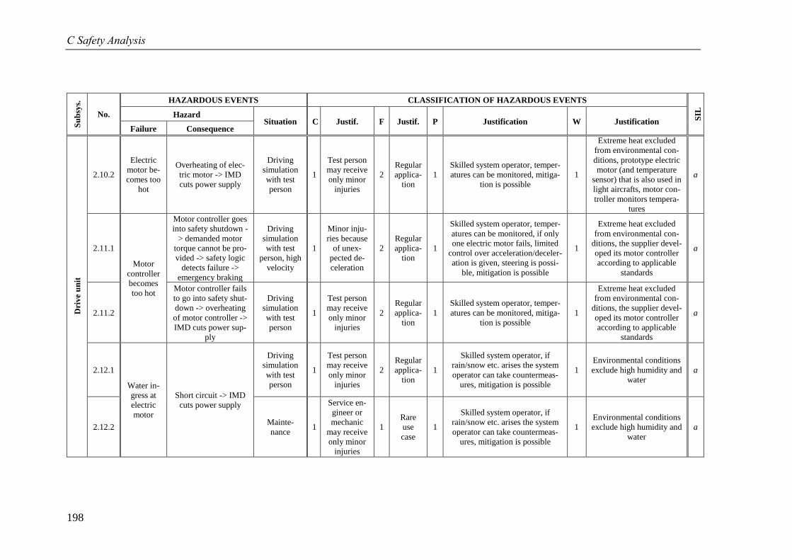
C Safety Analysis
198
Su
bsy
s.
No.
HAZARDOUS EVENTS CLASSIFICATION OF HAZARDOUS EVENTS
SIL
Hazard Situation C Justif. F Justif. P Justification W Justification
Failure Consequence
Dri
ve
un
it
2.10.2
Electric
motor be-
comes too
hot
Overheating of elec-
tric motor -> IMD
cuts power supply
Driving
simulation
with test
person
1
Test person
may receive
only minor
injuries
2
Regular
applica-
tion
1
Skilled system operator, temper-
atures can be monitored, mitiga-
tion is possible
1
Extreme heat excluded
from environmental con-
ditions, prototype electric
motor (and temperature
sensor) that is also used in
light aircrafts, motor con-
troller monitors tempera-
tures
a
2.11.1
Motor
controller
becomes
too hot
Motor controller goes
into safety shutdown -
> demanded motor
torque cannot be pro-
vided -> safety logic
detects failure ->
emergency braking
Driving
simulation
with test
person, high
velocity
1
Minor inju-
ries because
of unex-
pected de-
celeration
2
Regular
applica-
tion
1
Skilled system operator, temper-
atures can be monitored, if only
one electric motor fails, limited
control over acceleration/deceler-
ation is given, steering is possi-
ble, mitigation is possible
1
Extreme heat excluded
from environmental con-
ditions, the supplier devel-
oped its motor controller
according to applicable
standards
a
2.11.2
Motor controller fails
to go into safety shut-
down -> overheating
of motor controller ->
IMD cuts power sup-
ply
Driving
simulation
with test
person
1
Test person
may receive
only minor
injuries
2
Regular
applica-
tion
1
Skilled system operator, temper-
atures can be monitored, mitiga-
tion is possible
1
Extreme heat excluded
from environmental con-
ditions, the supplier devel-
oped its motor controller
according to applicable
standards
a
2.12.1
Water in-
gress at
electric
motor
Short circuit -> IMD
cuts power supply
Driving
simulation
with test
person
1
Test person
may receive
only minor
injuries
2
Regular
applica-
tion
1
Skilled system operator, if
rain/snow etc. arises the system
operator can take countermeas-
ures, mitigation is possible
1
Environmental conditions
exclude high humidity and
water
a
2.12.2 Mainte-
nance 1
Service en-
gineer or
mechanic
may receive
only minor
injuries
1
Rare
use
case
1
Skilled system operator, if
rain/snow etc. arises the system
operator can take countermeas-
ures, mitigation is possible
1
Environmental conditions
exclude high humidity and
water
a
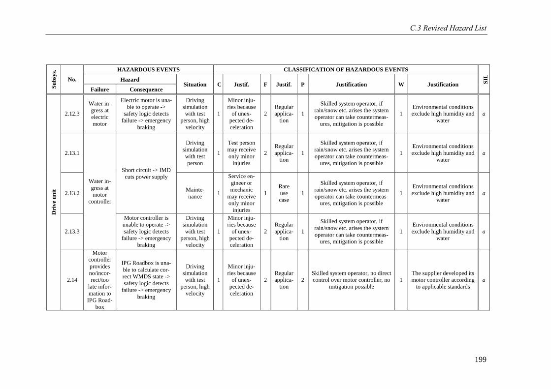
C.3 Revised Hazard List
199
Su
bsy
s.
No.
HAZARDOUS EVENTS CLASSIFICATION OF HAZARDOUS EVENTS
SIL
Hazard Situation C Justif. F Justif. P Justification W Justification
Failure Consequence
Dri
ve
un
it
2.12.3
Water in-
gress at
electric
motor
Electric motor is una-
ble to operate ->
safety logic detects
failure -> emergency
braking
Driving
simulation
with test
person, high
velocity
1
Minor inju-
ries because
of unex-
pected de-
celeration
2
Regular
applica-
tion
1
Skilled system operator, if
rain/snow etc. arises the system
operator can take countermeas-
ures, mitigation is possible
1
Environmental conditions
exclude high humidity and
water
a
2.13.1
Water in-
gress at
motor
controller
Short circuit -> IMD
cuts power supply
Driving
simulation
with test
person
1
Test person
may receive
only minor
injuries
2
Regular
applica-
tion
1
Skilled system operator, if
rain/snow etc. arises the system
operator can take countermeas-
ures, mitigation is possible
1
Environmental conditions
exclude high humidity and
water
a
2.13.2 Mainte-
nance 1
Service en-
gineer or
mechanic
may receive
only minor
injuries
1
Rare
use
case
1
Skilled system operator, if
rain/snow etc. arises the system
operator can take countermeas-
ures, mitigation is possible
1
Environmental conditions
exclude high humidity and
water
a
2.13.3
Motor controller is
unable to operate ->
safety logic detects
failure -> emergency
braking
Driving
simulation
with test
person, high
velocity
1
Minor inju-
ries because
of unex-
pected de-
celeration
2
Regular
applica-
tion
1
Skilled system operator, if
rain/snow etc. arises the system
operator can take countermeas-
ures, mitigation is possible
1
Environmental conditions
exclude high humidity and
water
a
2.14
Motor
controller
provides
no/incor-
rect/too
late infor-
mation to
IPG Road-
box
IPG Roadbox is una-
ble to calculate cor-
rect WMDS state ->
safety logic detects
failure -> emergency
braking
Driving
simulation
with test
person, high
velocity
1
Minor inju-
ries because
of unex-
pected de-
celeration
2
Regular
applica-
tion
2
Skilled system operator, no direct
control over motor controller, no
mitigation possible
1
The supplier developed its
motor controller according
to applicable standards
a
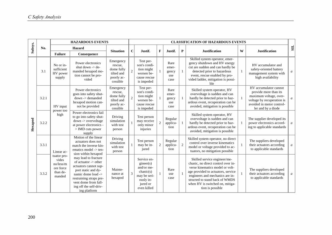
C Safety Analysis
200
Su
bsy
s.
No.
HAZARDOUS EVENTS CLASSIFICATION OF HAZARDOUS EVENTS
SIL
Hazard Situation C Justif. F Justif. P Justification W Justification
Failure Consequence
Hex
ap
od
3.1
No or in-
sufficient
HV power
supply
Power electronics
shut down -> de-
manded hexapod mo-
tion cannot be pro-
vided
Emergency
rescue,
dome fully
tilted and
poorly ac-
cessible
2
Test per-
son's condi-
tion might
worsen be-
cause rescue
is impeded
1
Rare
emer-
gency
use
case
1
Skilled system operator, emer-
gency shutdown and HV energy
cut are sudden and can hardly be
detected prior to hazardous
event, rescue enabled by pro-
vided ladder, mitigation is possi-
ble
1
HV accumulator and
safety-oriented battery
management system with
high availability
a
3.2.1
HV input
power too
high
Power electronics
goes into safety shut-
down -> demanded
hexapod motion can-
not be provided
Emergency
rescue,
dome fully
tilted and
poorly ac-
cessible
2
Test per-
son's condi-
tion might
worsen be-
cause rescue
is impeded
1
Rare
emer-
gency
use
case
1
Skilled system operator, HV
overvoltage is sudden and can
hardly be detected prior to haz-
ardous event, recuperation can be
avoided, mitigation is possible
1
HV accumulator cannot
provide more than its
maximum voltage, over-
voltage by recuperation is
avoided in motor control-
ler and by a diode
a
3.2.2
Power electronics fail
to go into safety shut-
down -> overvoltage
at power electronics -
> IMD cuts power
supply
Driving
simulation
with test
person
1
Test person
may receive
only minor
injuries
2
Regular
applica-
tion
1
Skilled system operator, HV
overvoltage is sudden and can
hardly be detected prior to haz-
ardous event, recuperation can be
avoided, mitigation is possible
1
The supplier developed its
power electronics accord-
ing to applicable standards
a
3.3.1
Linear ac-
tuator pro-
vides
no/less/m
ore force
than de-
manded
Motion of the linear
actuators does not
match the inverse kin-
ematics model -> ten-
sion within hexapod
may lead to fracture
of actuator -> other
actuators cannot sup-
port static and dy-
namic dome load ->
restraining straps pre-
vent dome from fall-
ing off the self-driv-
ing platform
Driving
simulation
with test
person
1
Test person
may be in-
jured
2
Regular
applica-
tion
2
Skilled system operator, no direct
control over inverse kinematics
model or voltage provided to ac-
tuators, no mitigation possible
1
The suppliers developed
their actuators according
to applicable standards
a
3.3.2
Mainte-
nance at
hexapod
3
Service en-
gineer(s)
and/or me-
chanic(s)
may be seri-
ously in-
jured or
even killed
1
Rare
use
case
1
Skilled service engineer/me-
chanic, no direct control over in-
verse kinematics model or volt-
age provided to actuators, service
engineers and mechanics are in-
structed to stand back of WMDS
when HV is switched on, mitiga-
tion is possible
1
The suppliers developed
their actuators according
to applicable standards
a
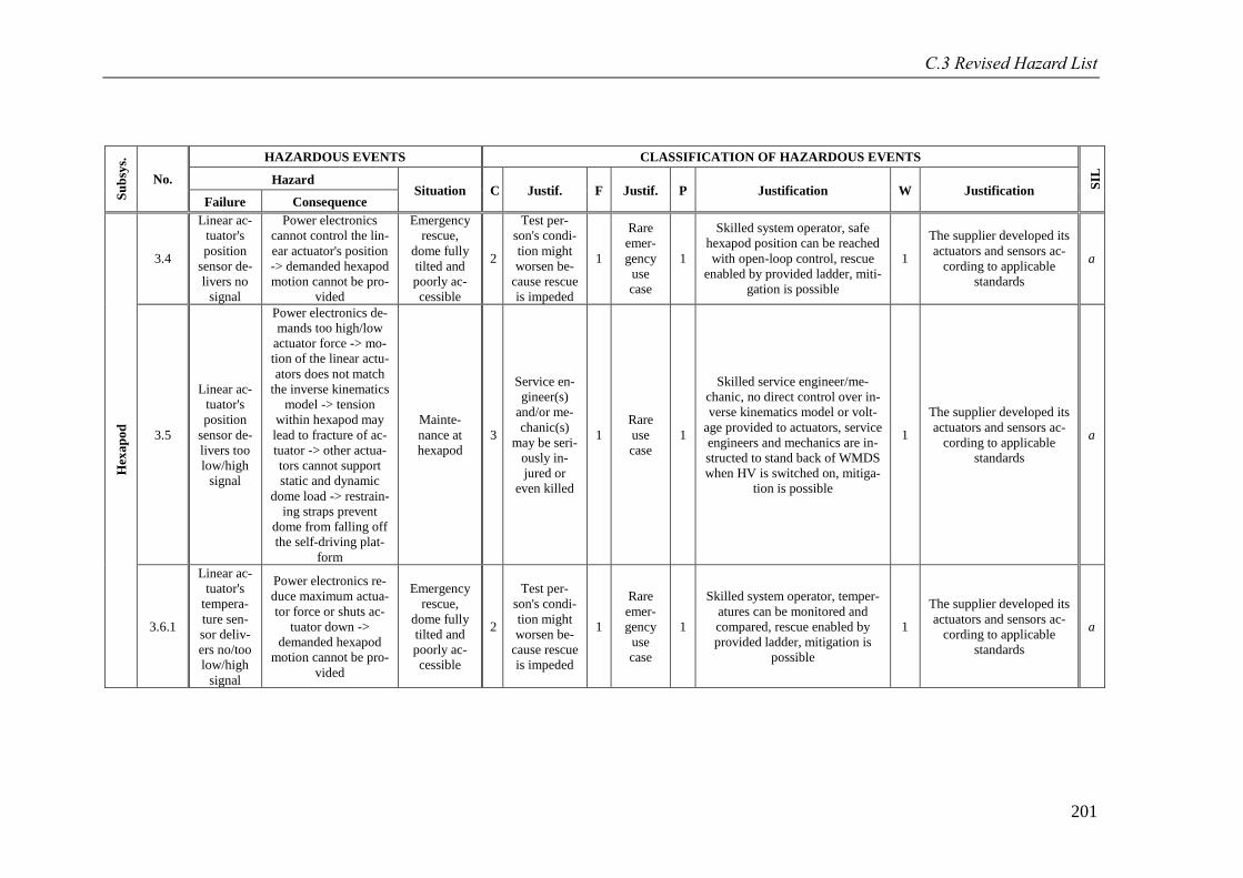
C.3 Revised Hazard List
201
Su
bsy
s.
No.
HAZARDOUS EVENTS CLASSIFICATION OF HAZARDOUS EVENTS
SIL
Hazard Situation C Justif. F Justif. P Justification W Justification
Failure Consequence
Hex
ap
od
3.4
Linear ac-
tuator's
position
sensor de-
livers no
signal
Power electronics
cannot control the lin-
ear actuator's position
-> demanded hexapod
motion cannot be pro-
vided
Emergency
rescue,
dome fully
tilted and
poorly ac-
cessible
2
Test per-
son's condi-
tion might
worsen be-
cause rescue
is impeded
1
Rare
emer-
gency
use
case
1
Skilled system operator, safe
hexapod position can be reached
with open-loop control, rescue
enabled by provided ladder, miti-
gation is possible
1
The supplier developed its
actuators and sensors ac-
cording to applicable
standards
a
3.5
Linear ac-
tuator's
position
sensor de-
livers too
low/high
signal
Power electronics de-
mands too high/low
actuator force -> mo-
tion of the linear actu-
ators does not match
the inverse kinematics
model -> tension
within hexapod may
lead to fracture of ac-
tuator -> other actua-
tors cannot support
static and dynamic
dome load -> restrain-
ing straps prevent
dome from falling off
the self-driving plat-
form
Mainte-
nance at
hexapod
3
Service en-
gineer(s)
and/or me-
chanic(s)
may be seri-
ously in-
jured or
even killed
1
Rare
use
case
1
Skilled service engineer/me-
chanic, no direct control over in-
verse kinematics model or volt-
age provided to actuators, service
engineers and mechanics are in-
structed to stand back of WMDS
when HV is switched on, mitiga-
tion is possible
1
The supplier developed its
actuators and sensors ac-
cording to applicable
standards
a
3.6.1
Linear ac-
tuator's
tempera-
ture sen-
sor deliv-
ers no/too
low/high
signal
Power electronics re-
duce maximum actua-
tor force or shuts ac-
tuator down ->
demanded hexapod
motion cannot be pro-
vided
Emergency
rescue,
dome fully
tilted and
poorly ac-
cessible
2
Test per-
son's condi-
tion might
worsen be-
cause rescue
is impeded
1
Rare
emer-
gency
use
case
1
Skilled system operator, temper-
atures can be monitored and
compared, rescue enabled by
provided ladder, mitigation is
possible
1
The supplier developed its
actuators and sensors ac-
cording to applicable
standards
a
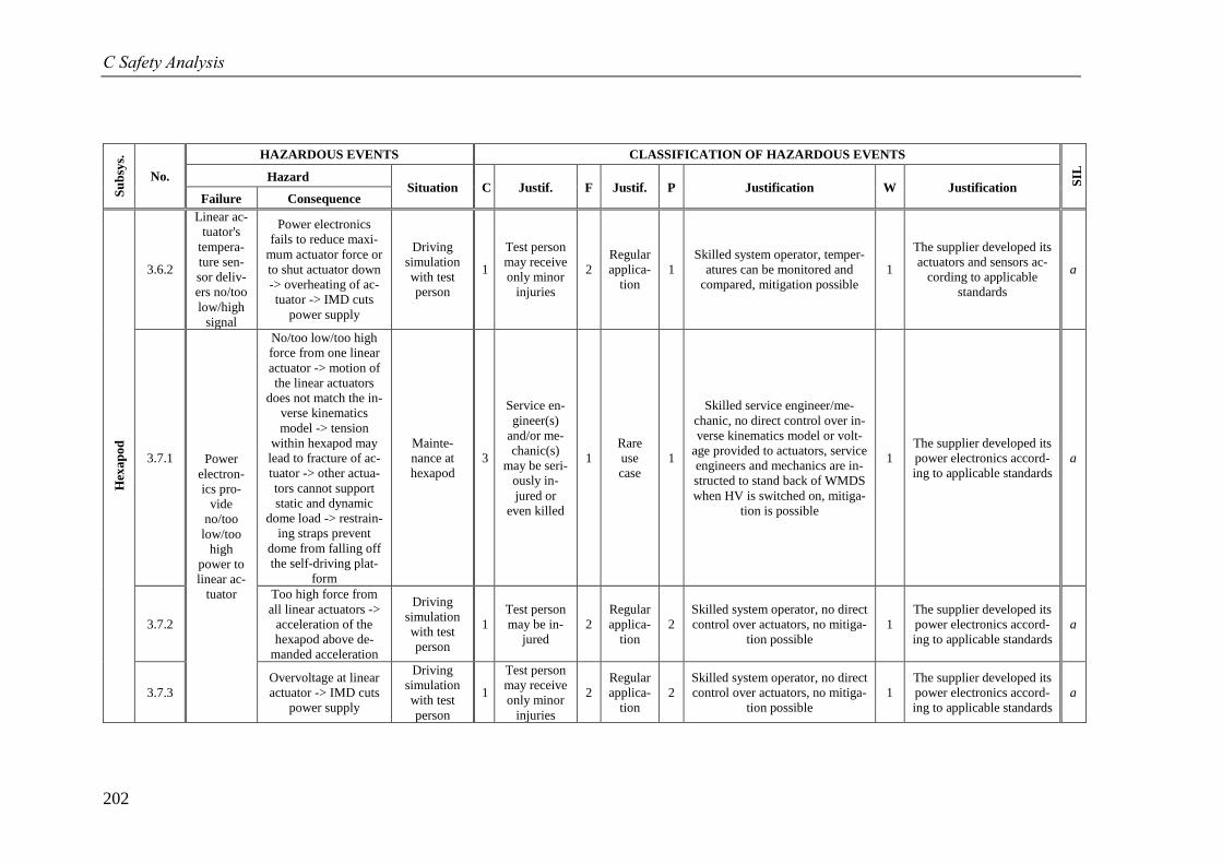
C Safety Analysis
202
Su
bsy
s.
No.
HAZARDOUS EVENTS CLASSIFICATION OF HAZARDOUS EVENTS
SIL
Hazard Situation C Justif. F Justif. P Justification W Justification
Failure Consequence
Hex
ap
od
3.6.2
Linear ac-
tuator's
tempera-
ture sen-
sor deliv-
ers no/too
low/high
signal
Power electronics
fails to reduce maxi-
mum actuator force or
to shut actuator down
-> overheating of ac-
tuator -> IMD cuts
power supply
Driving
simulation
with test
person
1
Test person
may receive
only minor
injuries
2
Regular
applica-
tion
1
Skilled system operator, temper-
atures can be monitored and
compared, mitigation possible
1
The supplier developed its
actuators and sensors ac-
cording to applicable
standards
a
3.7.1 Power
electron-
ics pro-
vide
no/too
low/too
high
power to
linear ac-
tuator
No/too low/too high
force from one linear
actuator -> motion of
the linear actuators
does not match the in-
verse kinematics
model -> tension
within hexapod may
lead to fracture of ac-
tuator -> other actua-
tors cannot support
static and dynamic
dome load -> restrain-
ing straps prevent
dome from falling off
the self-driving plat-
form
Mainte-
nance at
hexapod
3
Service en-
gineer(s)
and/or me-
chanic(s)
may be seri-
ously in-
jured or
even killed
1
Rare
use
case
1
Skilled service engineer/me-
chanic, no direct control over in-
verse kinematics model or volt-
age provided to actuators, service
engineers and mechanics are in-
structed to stand back of WMDS
when HV is switched on, mitiga-
tion is possible
1
The supplier developed its
power electronics accord-
ing to applicable standards
a
3.7.2
Too high force from
all linear actuators ->
acceleration of the
hexapod above de-
manded acceleration
Driving
simulation
with test
person
1
Test person
may be in-
jured
2
Regular
applica-
tion
2
Skilled system operator, no direct
control over actuators, no mitiga-
tion possible
1
The supplier developed its
power electronics accord-
ing to applicable standards
a
3.7.3
Overvoltage at linear
actuator -> IMD cuts
power supply
Driving
simulation
with test
person
1
Test person
may receive
only minor
injuries
2
Regular
applica-
tion
2
Skilled system operator, no direct
control over actuators, no mitiga-
tion possible
1
The supplier developed its
power electronics accord-
ing to applicable standards
a
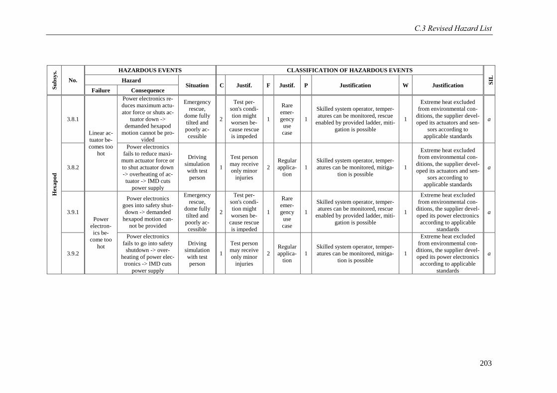
C.3 Revised Hazard List
203
Su
bsy
s.
No.
HAZARDOUS EVENTS CLASSIFICATION OF HAZARDOUS EVENTS
SIL
Hazard Situation C Justif. F Justif. P Justification W Justification
Failure Consequence
Hex
ap
od
3.8.1
Linear ac-
tuator be-
comes too
hot
Power electronics re-
duces maximum actu-
ator force or shuts ac-
tuator down ->
demanded hexapod
motion cannot be pro-
vided
Emergency
rescue,
dome fully
tilted and
poorly ac-
cessible
2
Test per-
son's condi-
tion might
worsen be-
cause rescue
is impeded
1
Rare
emer-
gency
use
case
1
Skilled system operator, temper-
atures can be monitored, rescue
enabled by provided ladder, miti-
gation is possible
1
Extreme heat excluded
from environmental con-
ditions, the supplier devel-
oped its actuators and sen-
sors according to
applicable standards
a
3.8.2
Power electronics
fails to reduce maxi-
mum actuator force or
to shut actuator down
-> overheating of ac-
tuator -> IMD cuts
power supply
Driving
simulation
with test
person
1
Test person
may receive
only minor
injuries
2
Regular
applica-
tion
1
Skilled system operator, temper-
atures can be monitored, mitiga-
tion is possible
1
Extreme heat excluded
from environmental con-
ditions, the supplier devel-
oped its actuators and sen-
sors according to
applicable standards
a
3.9.1
Power
electron-
ics be-
come too
hot
Power electronics
goes into safety shut-
down -> demanded
hexapod motion can-
not be provided
Emergency
rescue,
dome fully
tilted and
poorly ac-
cessible
2
Test per-
son's condi-
tion might
worsen be-
cause rescue
is impeded
1
Rare
emer-
gency
use
case
1
Skilled system operator, temper-
atures can be monitored, rescue
enabled by provided ladder, miti-
gation is possible
1
Extreme heat excluded
from environmental con-
ditions, the supplier devel-
oped its power electronics
according to applicable
standards
a
3.9.2
Power electronics
fails to go into safety
shutdown -> over-
heating of power elec-
tronics -> IMD cuts
power supply
Driving
simulation
with test
person
1
Test person
may receive
only minor
injuries
2
Regular
applica-
tion
1
Skilled system operator, temper-
atures can be monitored, mitiga-
tion is possible
1
Extreme heat excluded
from environmental con-
ditions, the supplier devel-
oped its power electronics
according to applicable
standards
a
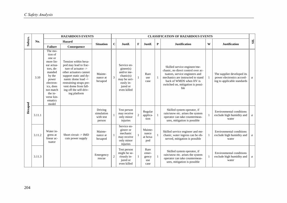
C Safety Analysis
204
Su
bsy
s.
No.
HAZARDOUS EVENTS CLASSIFICATION OF HAZARDOUS EVENTS
SIL
Hazard Situation C Justif. F Justif. P Justification W Justification
Failure Consequence
Hex
ap
od
3.10
The mo-
tion of
one or
more lin-
ear actua-
tors, de-
manded
by the
power
electron-
ics, does
not match
the in-
verse kin-
ematics
model
Tension within hexa-
pod may lead to frac-
ture of actuator ->
other actuators cannot
support static and dy-
namic dome load ->
restraining straps pre-
vent dome from fall-
ing off the self-driv-
ing platform
Mainte-
nance at
hexapod
3
Service en-
gineer(s)
and/or me-
chanic(s)
may be seri-
ously in-
jured or
even killed
1
Rare
use
case
1
Skilled service engineer/me-
chanic, no direct control over ac-
tuators, service engineers and
mechanics are instructed to stand
back of WMDS when HV is
switched on, mitigation is possi-
ble
1
The supplier developed its
power electronics accord-
ing to applicable standards
a
3.11.1
Water in-
gress at
linear ac-
tuator
Short circuit -> IMD
cuts power supply
Driving
simulation
with test
person
1
Test person
may receive
only minor
injuries
2
Regular
applica-
tion
1
Skilled system operator, if
rain/snow etc. arises the system
operator can take countermeas-
ures, mitigation is possible
1
Environmental conditions
exclude high humidity and
water
a
3.11.2
Mainte-
nance at
hexapod
1
Service en-
gineer or
mechanic
may receive
only minor
injuries
1
Mainte-
nance
at hexa-
pod
1
Skilled service engineer and me-
chanic, water ingress can be ob-
served, mitigation is possible
1
Environmental conditions
exclude high humidity and
water
a
3.11.3 Emergency
rescue 2
Test person
might be se-
riously in-
jured or
even killed
1
Rare
emer-
gency
use
case
1
Skilled system operator, if
rain/snow etc. arises the system
operator can take countermeas-
ures, mitigation is possible
1
Environmental conditions
exclude high humidity and
water
a
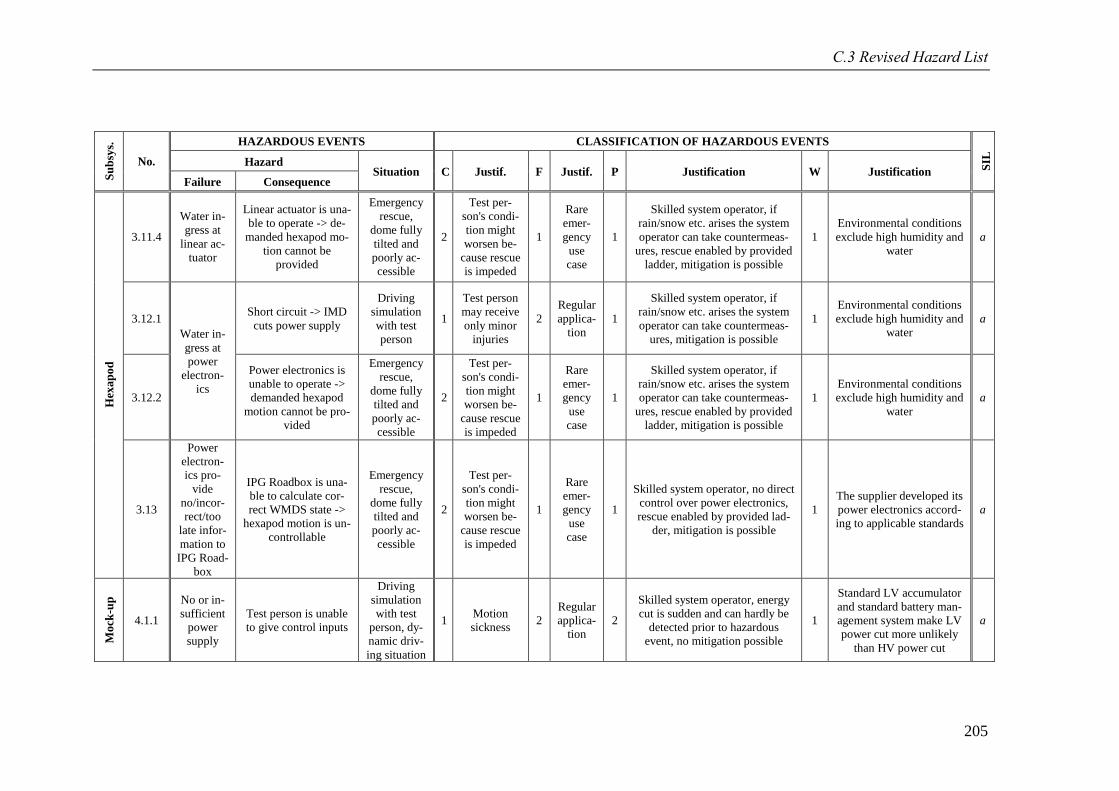
C.3 Revised Hazard List
205
Su
bsy
s.
No.
HAZARDOUS EVENTS CLASSIFICATION OF HAZARDOUS EVENTS
SIL
Hazard Situation C Justif. F Justif. P Justification W Justification
Failure Consequence
Hex
ap
od
3.11.4
Water in-
gress at
linear ac-
tuator
Linear actuator is una-
ble to operate -> de-
manded hexapod mo-
tion cannot be
provided
Emergency
rescue,
dome fully
tilted and
poorly ac-
cessible
2
Test per-
son's condi-
tion might
worsen be-
cause rescue
is impeded
1
Rare
emer-
gency
use
case
1
Skilled system operator, if
rain/snow etc. arises the system
operator can take countermeas-
ures, rescue enabled by provided
ladder, mitigation is possible
1
Environmental conditions
exclude high humidity and
water
a
3.12.1
Water in-
gress at
power
electron-
ics
Short circuit -> IMD
cuts power supply
Driving
simulation
with test
person
1
Test person
may receive
only minor
injuries
2
Regular
applica-
tion
1
Skilled system operator, if
rain/snow etc. arises the system
operator can take countermeas-
ures, mitigation is possible
1
Environmental conditions
exclude high humidity and
water
a
3.12.2
Power electronics is
unable to operate ->
demanded hexapod
motion cannot be pro-
vided
Emergency
rescue,
dome fully
tilted and
poorly ac-
cessible
2
Test per-
son's condi-
tion might
worsen be-
cause rescue
is impeded
1
Rare
emer-
gency
use
case
1
Skilled system operator, if
rain/snow etc. arises the system
operator can take countermeas-
ures, rescue enabled by provided
ladder, mitigation is possible
1
Environmental conditions
exclude high humidity and
water
a
3.13
Power
electron-
ics pro-
vide
no/incor-
rect/too
late infor-
mation to
IPG Road-
box
IPG Roadbox is una-
ble to calculate cor-
rect WMDS state ->
hexapod motion is un-
controllable
Emergency
rescue,
dome fully
tilted and
poorly ac-
cessible
2
Test per-
son's condi-
tion might
worsen be-
cause rescue
is impeded
1
Rare
emer-
gency
use
case
1
Skilled system operator, no direct
control over power electronics,
rescue enabled by provided lad-
der, mitigation is possible
1
The supplier developed its
power electronics accord-
ing to applicable standards
a
Mo
ck-u
p
4.1.1
No or in-
sufficient
power
supply
Test person is unable
to give control inputs
Driving
simulation
with test
person, dy-
namic driv-
ing situation
1 Motion
sickness 2
Regular
applica-
tion
2
Skilled system operator, energy
cut is sudden and can hardly be
detected prior to hazardous
event, no mitigation possible
1
Standard LV accumulator
and standard battery man-
agement system make LV
power cut more unlikely
than HV power cut
a
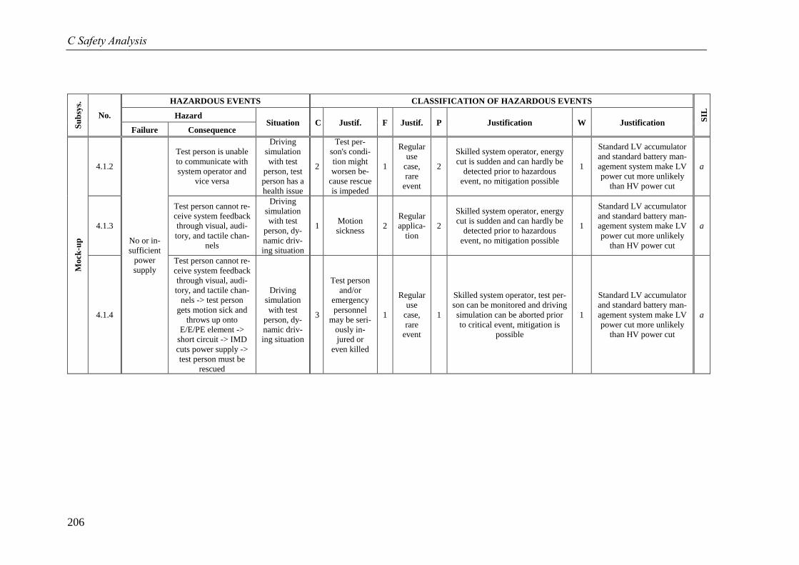
C Safety Analysis
206
Su
bsy
s.
No.
HAZARDOUS EVENTS CLASSIFICATION OF HAZARDOUS EVENTS
SIL
Hazard Situation C Justif. F Justif. P Justification W Justification
Failure Consequence
Mo
ck-u
p
4.1.2
No or in-
sufficient
power
supply
Test person is unable
to communicate with
system operator and
vice versa
Driving
simulation
with test
person, test
person has a
health issue
2
Test per-
son's condi-
tion might
worsen be-
cause rescue
is impeded
1
Regular
use
case,
rare
event
2
Skilled system operator, energy
cut is sudden and can hardly be
detected prior to hazardous
event, no mitigation possible
1
Standard LV accumulator
and standard battery man-
agement system make LV
power cut more unlikely
than HV power cut
a
4.1.3
Test person cannot re-
ceive system feedback
through visual, audi-
tory, and tactile chan-
nels
Driving
simulation
with test
person, dy-
namic driv-
ing situation
1 Motion
sickness 2
Regular
applica-
tion
2
Skilled system operator, energy
cut is sudden and can hardly be
detected prior to hazardous
event, no mitigation possible
1
Standard LV accumulator
and standard battery man-
agement system make LV
power cut more unlikely
than HV power cut
a
4.1.4
Test person cannot re-
ceive system feedback
through visual, audi-
tory, and tactile chan-
nels -> test person
gets motion sick and
throws up onto
E/E/PE element ->
short circuit -> IMD
cuts power supply ->
test person must be
rescued
Driving
simulation
with test
person, dy-
namic driv-
ing situation
3
Test person
and/or
emergency
personnel
may be seri-
ously in-
jured or
even killed
1
Regular
use
case,
rare
event
1
Skilled system operator, test per-
son can be monitored and driving
simulation can be aborted prior
to critical event, mitigation is
possible
1
Standard LV accumulator
and standard battery man-
agement system make LV
power cut more unlikely
than HV power cut
a
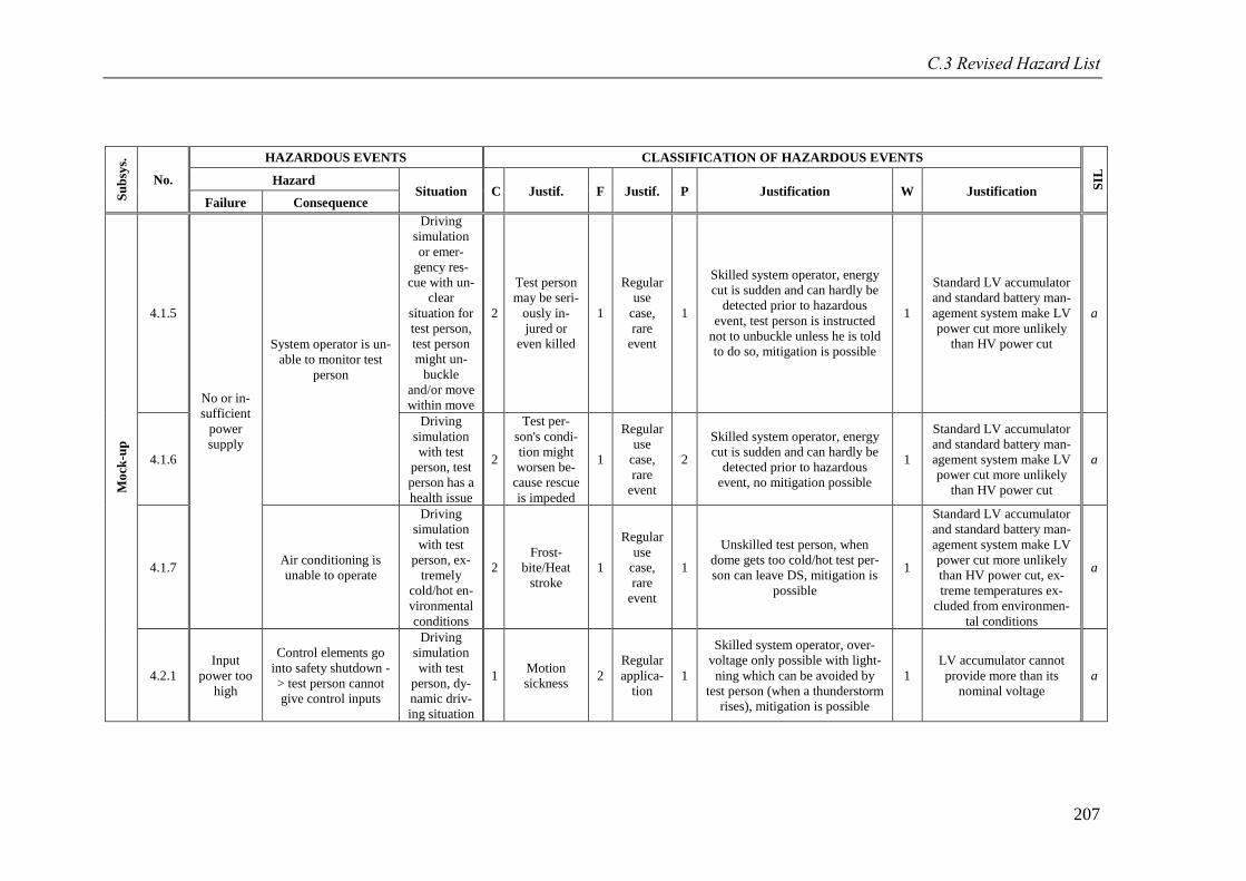
C.3 Revised Hazard List
207
Su
bsy
s.
No.
HAZARDOUS EVENTS CLASSIFICATION OF HAZARDOUS EVENTS
SIL
Hazard Situation C Justif. F Justif. P Justification W Justification
Failure Consequence
Mo
ck-u
p
4.1.5
No or in-
sufficient
power
supply
System operator is un-
able to monitor test
person
Driving
simulation
or emer-
gency res-
cue with un-
clear
situation for
test person,
test person
might un-
buckle
and/or move
within move
2
Test person
may be seri-
ously in-
jured or
even killed
1
Regular
use
case,
rare
event
1
Skilled system operator, energy
cut is sudden and can hardly be
detected prior to hazardous
event, test person is instructed
not to unbuckle unless he is told
to do so, mitigation is possible
1
Standard LV accumulator
and standard battery man-
agement system make LV
power cut more unlikely
than HV power cut
a
4.1.6
Driving
simulation
with test
person, test
person has a
health issue
2
Test per-
son's condi-
tion might
worsen be-
cause rescue
is impeded
1
Regular
use
case,
rare
event
2
Skilled system operator, energy
cut is sudden and can hardly be
detected prior to hazardous
event, no mitigation possible
1
Standard LV accumulator
and standard battery man-
agement system make LV
power cut more unlikely
than HV power cut
a
4.1.7 Air conditioning is
unable to operate
Driving
simulation
with test
person, ex-
tremely
cold/hot en-
vironmental
conditions
2
Frost-
bite/Heat
stroke
1
Regular
use
case,
rare
event
1
Unskilled test person, when
dome gets too cold/hot test per-
son can leave DS, mitigation is
possible
1
Standard LV accumulator
and standard battery man-
agement system make LV
power cut more unlikely
than HV power cut, ex-
treme temperatures ex-
cluded from environmen-
tal conditions
a
4.2.1
Input
power too
high
Control elements go
into safety shutdown -
> test person cannot
give control inputs
Driving
simulation
with test
person, dy-
namic driv-
ing situation
1 Motion
sickness 2
Regular
applica-
tion
1
Skilled system operator, over-
voltage only possible with light-
ning which can be avoided by
test person (when a thunderstorm
rises), mitigation is possible
1
LV accumulator cannot
provide more than its
nominal voltage
a
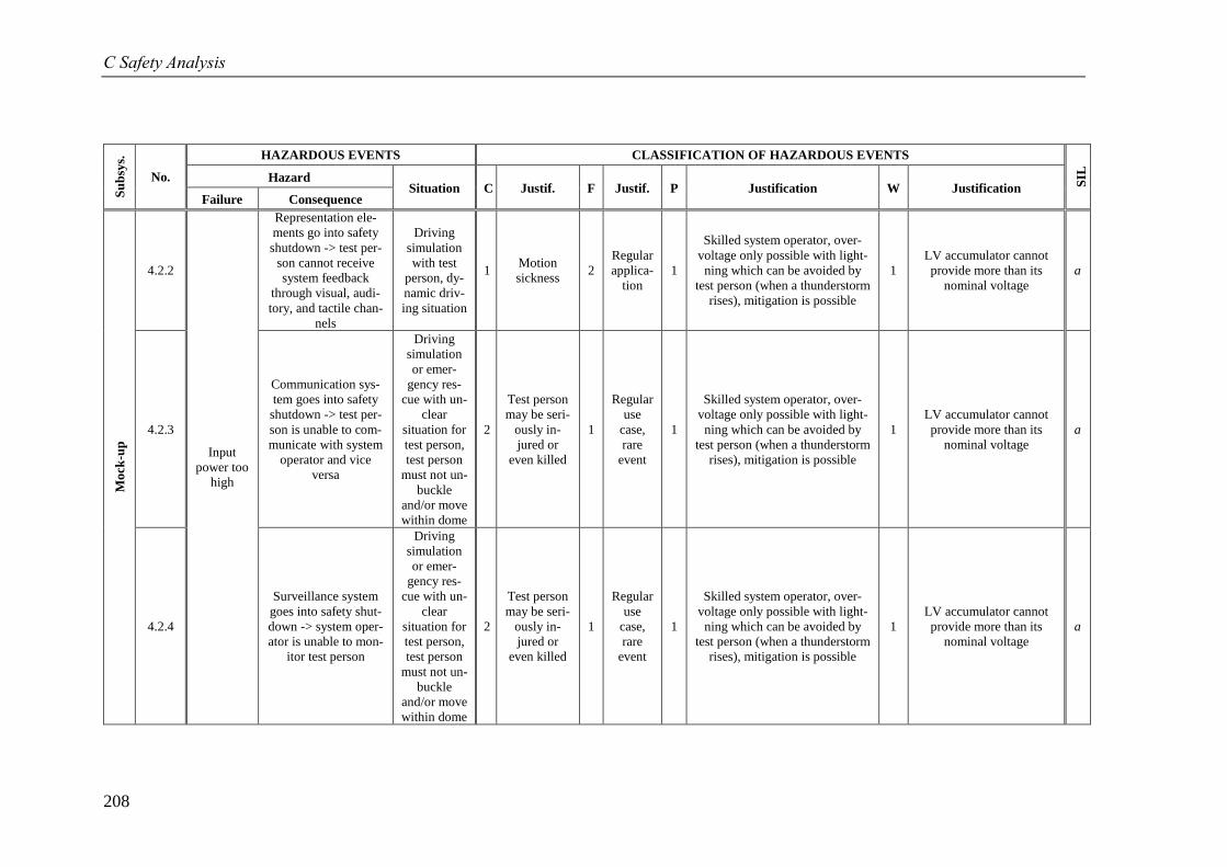
C Safety Analysis
208
Su
bsy
s.
No.
HAZARDOUS EVENTS CLASSIFICATION OF HAZARDOUS EVENTS
SIL
Hazard Situation C Justif. F Justif. P Justification W Justification
Failure Consequence
Mo
ck-u
p
4.2.2
Input
power too
high
Representation ele-
ments go into safety
shutdown -> test per-
son cannot receive
system feedback
through visual, audi-
tory, and tactile chan-
nels
Driving
simulation
with test
person, dy-
namic driv-
ing situation
1 Motion
sickness 2
Regular
applica-
tion
1
Skilled system operator, over-
voltage only possible with light-
ning which can be avoided by
test person (when a thunderstorm
rises), mitigation is possible
1
LV accumulator cannot
provide more than its
nominal voltage
a
4.2.3
Communication sys-
tem goes into safety
shutdown -> test per-
son is unable to com-
municate with system
operator and vice
versa
Driving
simulation
or emer-
gency res-
cue with un-
clear
situation for
test person,
test person
must not un-
buckle
and/or move
within dome
2
Test person
may be seri-
ously in-
jured or
even killed
1
Regular
use
case,
rare
event
1
Skilled system operator, over-
voltage only possible with light-
ning which can be avoided by
test person (when a thunderstorm
rises), mitigation is possible
1
LV accumulator cannot
provide more than its
nominal voltage
a
4.2.4
Surveillance system
goes into safety shut-
down -> system oper-
ator is unable to mon-
itor test person
Driving
simulation
or emer-
gency res-
cue with un-
clear
situation for
test person,
test person
must not un-
buckle
and/or move
within dome
2
Test person
may be seri-
ously in-
jured or
even killed
1
Regular
use
case,
rare
event
1
Skilled system operator, over-
voltage only possible with light-
ning which can be avoided by
test person (when a thunderstorm
rises), mitigation is possible
1
LV accumulator cannot
provide more than its
nominal voltage
a
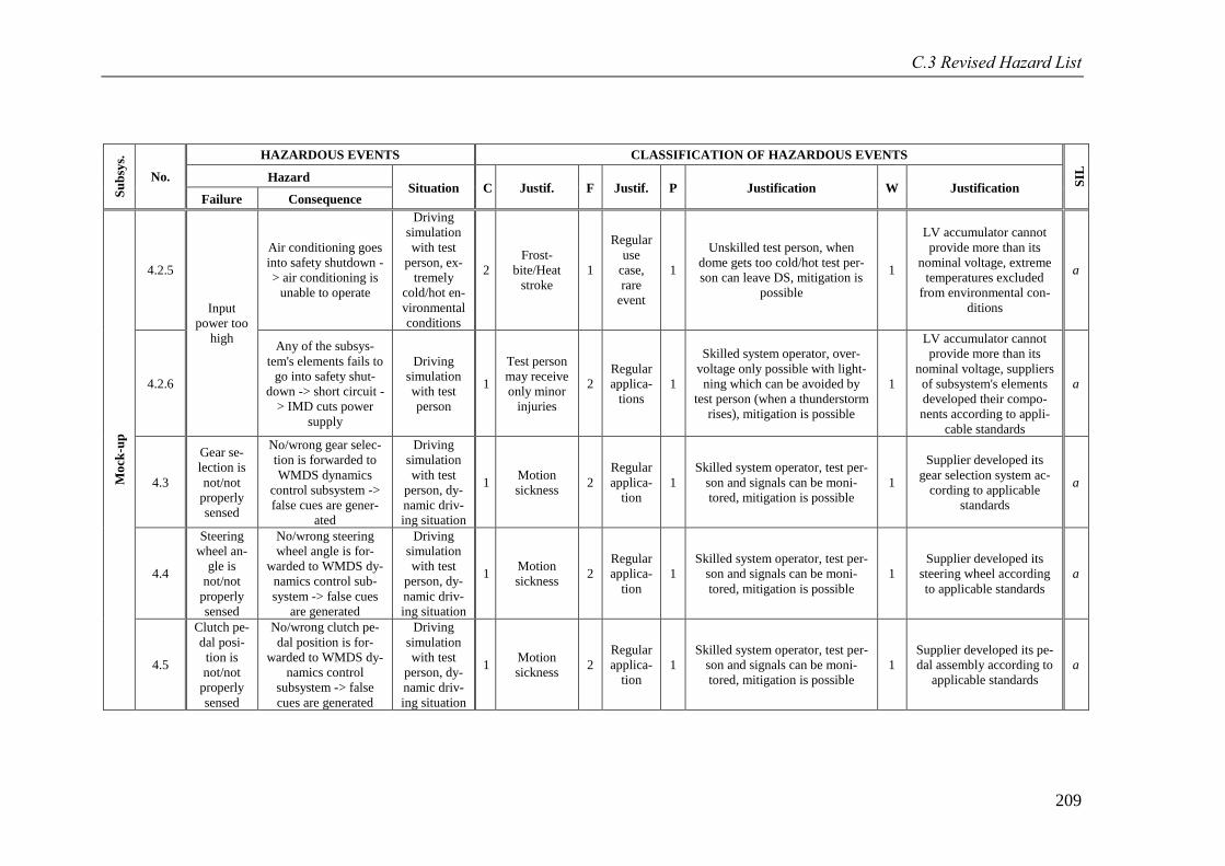
C.3 Revised Hazard List
209
Su
bsy
s.
No.
HAZARDOUS EVENTS CLASSIFICATION OF HAZARDOUS EVENTS
SIL
Hazard Situation C Justif. F Justif. P Justification W Justification
Failure Consequence
Mo
ck-u
p
4.2.5
Input
power too
high
Air conditioning goes
into safety shutdown -
> air conditioning is
unable to operate
Driving
simulation
with test
person, ex-
tremely
cold/hot en-
vironmental
conditions
2
Frost-
bite/Heat
stroke
1
Regular
use
case,
rare
event
1
Unskilled test person, when
dome gets too cold/hot test per-
son can leave DS, mitigation is
possible
1
LV accumulator cannot
provide more than its
nominal voltage, extreme
temperatures excluded
from environmental con-
ditions
a
4.2.6
Any of the subsys-
tem's elements fails to
go into safety shut-
down -> short circuit -
> IMD cuts power
supply
Driving
simulation
with test
person
1
Test person
may receive
only minor
injuries
2
Regular
applica-
tions
1
Skilled system operator, over-
voltage only possible with light-
ning which can be avoided by
test person (when a thunderstorm
rises), mitigation is possible
1
LV accumulator cannot
provide more than its
nominal voltage, suppliers
of subsystem's elements
developed their compo-
nents according to appli-
cable standards
a
4.3
Gear se-
lection is
not/not
properly
sensed
No/wrong gear selec-
tion is forwarded to
WMDS dynamics
control subsystem ->
false cues are gener-
ated
Driving
simulation
with test
person, dy-
namic driv-
ing situation
1 Motion
sickness 2
Regular
applica-
tion
1
Skilled system operator, test per-
son and signals can be moni-
tored, mitigation is possible
1
Supplier developed its
gear selection system ac-
cording to applicable
standards
a
4.4
Steering
wheel an-
gle is
not/not
properly
sensed
No/wrong steering
wheel angle is for-
warded to WMDS dy-
namics control sub-
system -> false cues
are generated
Driving
simulation
with test
person, dy-
namic driv-
ing situation
1 Motion
sickness 2
Regular
applica-
tion
1
Skilled system operator, test per-
son and signals can be moni-
tored, mitigation is possible
1
Supplier developed its
steering wheel according
to applicable standards
a
4.5
Clutch pe-
dal posi-
tion is
not/not
properly
sensed
No/wrong clutch pe-
dal position is for-
warded to WMDS dy-
namics control
subsystem -> false
cues are generated
Driving
simulation
with test
person, dy-
namic driv-
ing situation
1 Motion
sickness 2
Regular
applica-
tion
1
Skilled system operator, test per-
son and signals can be moni-
tored, mitigation is possible
1
Supplier developed its pe-
dal assembly according to
applicable standards
a
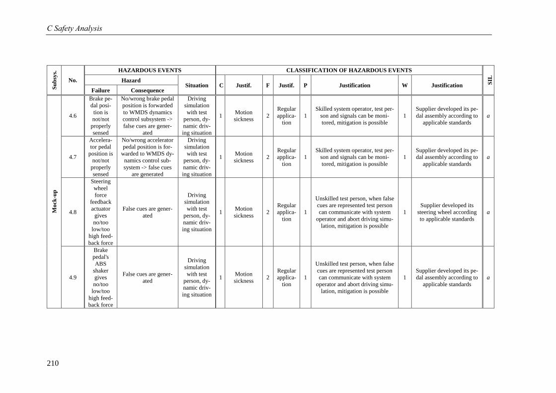
C Safety Analysis
210
Su
bsy
s.
No.
HAZARDOUS EVENTS CLASSIFICATION OF HAZARDOUS EVENTS
SIL
Hazard Situation C Justif. F Justif. P Justification W Justification
Failure Consequence
Mo
ck-u
p
4.6
Brake pe-
dal posi-
tion is
not/not
properly
sensed
No/wrong brake pedal
position is forwarded
to WMDS dynamics
control subsystem ->
false cues are gener-
ated
Driving
simulation
with test
person, dy-
namic driv-
ing situation
1 Motion
sickness 2
Regular
applica-
tion
1
Skilled system operator, test per-
son and signals can be moni-
tored, mitigation is possible
1
Supplier developed its pe-
dal assembly according to
applicable standards
a
4.7
Accelera-
tor pedal
position is
not/not
properly
sensed
No/wrong accelerator
pedal position is for-
warded to WMDS dy-
namics control sub-
system -> false cues
are generated
Driving
simulation
with test
person, dy-
namic driv-
ing situation
1 Motion
sickness 2
Regular
applica-
tion
1
Skilled system operator, test per-
son and signals can be moni-
tored, mitigation is possible
1
Supplier developed its pe-
dal assembly according to
applicable standards
a
4.8
Steering
wheel
force
feedback
actuator
gives
no/too
low/too
high feed-
back force
False cues are gener-
ated
Driving
simulation
with test
person, dy-
namic driv-
ing situation
1 Motion
sickness 2
Regular
applica-
tion
1
Unskilled test person, when false
cues are represented test person
can communicate with system
operator and abort driving simu-
lation, mitigation is possible
1
Supplier developed its
steering wheel according
to applicable standards
a
4.9
Brake
pedal's
ABS
shaker
gives
no/too
low/too
high feed-
back force
False cues are gener-
ated
Driving
simulation
with test
person, dy-
namic driv-
ing situation
1 Motion
sickness 2
Regular
applica-
tion
1
Unskilled test person, when false
cues are represented test person
can communicate with system
operator and abort driving simu-
lation, mitigation is possible
1
Supplier developed its pe-
dal assembly according to
applicable standards
a
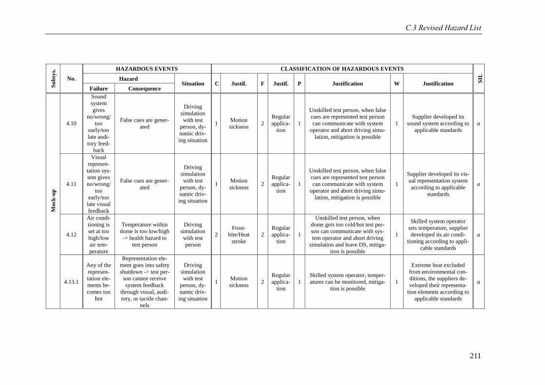
C.3 Revised Hazard List
211
Su
bsy
s.
No.
HAZARDOUS EVENTS CLASSIFICATION OF HAZARDOUS EVENTS
SIL
Hazard Situation C Justif. F Justif. P Justification W Justification
Failure Consequence
Mo
ck-u
p
4.10
Sound
system
gives
no/wrong/
too
early/too
late audi-
tory feed-
back
False cues are gener-
ated
Driving
simulation
with test
person, dy-
namic driv-
ing situation
1 Motion
sickness 2
Regular
applica-
tion
1
Unskilled test person, when false
cues are represented test person
can communicate with system
operator and abort driving simu-
lation, mitigation is possible
1
Supplier developed its
sound system according to
applicable standards
a
4.11
Visual
represen-
tation sys-
tem gives
no/wrong/
too
early/too
late visual
feedback
False cues are gener-
ated
Driving
simulation
with test
person, dy-
namic driv-
ing situation
1 Motion
sickness 2
Regular
applica-
tion
1
Unskilled test person, when false
cues are represented test person
can communicate with system
operator and abort driving simu-
lation, mitigation is possible
1
Supplier developed its vis-
ual representation system
according to applicable
standards
a
4.12
Air condi-
tioning is
set at too
high/low
air tem-
perature
Temperature within
dome is too low/high
-> health hazard to
test person
Driving
simulation
with test
person
2
Frost-
bite/Heat
stroke
2
Regular
applica-
tion
1
Unskilled test person, when
dome gets too cold/hot test per-
son can communicate with sys-
tem operator and abort driving
simulation and leave DS, mitiga-
tion is possible
1
Skilled system operator
sets temperature, supplier
developed its air condi-
tioning according to appli-
cable standards
a
4.13.1
Any of the
represen-
tation ele-
ments be-
comes too
hot
Representation ele-
ment goes into safety
shutdown -> test per-
son cannot receive
system feedback
through visual, audi-
tory, or tactile chan-
nels
Driving
simulation
with test
person, dy-
namic driv-
ing situation
1 Motion
sickness 2
Regular
applica-
tion
1
Skilled system operator, temper-
atures can be monitored, mitiga-
tion is possible
1
Extreme heat excluded
from environmental con-
ditions, the suppliers de-
veloped their representa-
tion elements according to
applicable standards
a
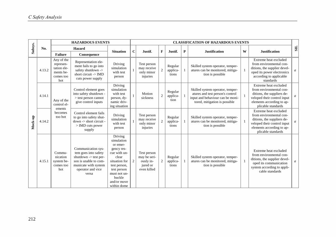
C Safety Analysis
212
Su
bsy
s.
No.
HAZARDOUS EVENTS CLASSIFICATION OF HAZARDOUS EVENTS
SIL
Hazard Situation C Justif. F Justif. P Justification W Justification
Failure Consequence
Mo
ck-u
p
4.13.2
Any of the
represen-
tation ele-
ments be-
comes too
hot
Representation ele-
ment fails to go into
safety shutdown ->
short circuit -> IMD
cuts power supply
Driving
simulation
with test
person
1
Test person
may receive
only minor
injuries
2
Regular
applica-
tions
1
Skilled system operator, temper-
atures can be monitored, mitiga-
tion is possible
1
Extreme heat excluded
from environmental con-
ditions, the supplier devel-
oped its power electronics
according to applicable
standards
a
4.14.1
Any of the
control el-
ements
becomes
too hot
Control element goes
into safety shutdown -
> test person cannot
give control inputs
Driving
simulation
with test
person, dy-
namic driv-
ing situation
1 Motion
sickness 2
Regular
applica-
tion
1
Skilled system operator, temper-
atures and test person's control
input and behaviour can be moni-
tored, mitigation is possible
1
Extreme heat excluded
from environmental con-
ditions, the suppliers de-
veloped their control input
elements according to ap-
plicable standards
a
4.14.2
Control element fails
to go into safety shut-
down -> short circuit -
> IMD cuts power
supply
Driving
simulation
with test
person
1
Test person
may receive
only minor
injuries
2
Regular
applica-
tions
1
Skilled system operator, temper-
atures can be monitored, mitiga-
tion is possible
1
Extreme heat excluded
from environmental con-
ditions, the suppliers de-
veloped their control input
elements according to ap-
plicable standards
a
4.15.1
Commu-
nication
system be-
comes too
hot
Communication sys-
tem goes into safety
shutdown -> test per-
son is unable to com-
municate with system
operator and vice
versa
Driving
simulation
or emer-
gency res-
cue with un-
clear
situation for
test person,
test person
must not un-
buckle
and/or move
within dome
2
Test person
may be seri-
ously in-
jured or
even killed
2
Regular
applica-
tions
1
Skilled system operator, temper-
atures can be monitored, mitiga-
tion is possible
1
Extreme heat excluded
from environmental con-
ditions, the supplier devel-
oped its communication
system according to appli-
cable standards
a
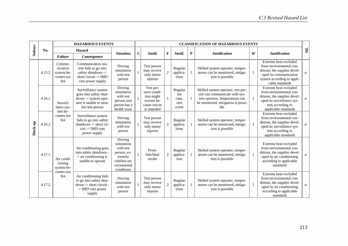
C.3 Revised Hazard List
213
Su
bsy
s.
No.
HAZARDOUS EVENTS CLASSIFICATION OF HAZARDOUS EVENTS
SIL
Hazard Situation C Justif. F Justif. P Justification W Justification
Failure Consequence
Mo
ck-u
p
4.15.2
Commu-
nication
system be-
comes too
hot
Communication sys-
tem fails to go into
safety shutdown ->
short circuit -> IMD
cuts power supply
Driving
simulation
with test
person
1
Test person
may receive
only minor
injuries
2
Regular
applica-
tions
1
Skilled system operator, temper-
atures can be monitored, mitiga-
tion is possible
1
Extreme heat excluded
from environmental con-
ditions, the supplier devel-
oped its communication
system according to appli-
cable standards
a
4.16.1
Surveil-
lance sys-
tem be-
comes too
hot
Surveillance system
goes into safety shut-
down -> system oper-
ator is unable to mon-
itor test person
Driving
simulation
with test
person, test
person has a
health issue
2
Test per-
son's condi-
tion might
worsen be-
cause rescue
is impeded
1
Regular
use
case,
rare
event
1
Skilled system operator, test per-
son can communicate with sys-
tem operator, temperatures can
be monitored, mitigation is possi-
ble
1
Extreme heat excluded
from environmental con-
ditions, the supplier devel-
oped its surveillance sys-
tem according to
applicable standards
a
4.16.2
Surveillance system
fails to go into safety
shutdown -> short cir-
cuit -> IMD cuts
power supply
Driving
simulation
with test
person
1
Test person
may receive
only minor
injuries
2
Regular
applica-
tions
1
Skilled system operator, temper-
atures can be monitored, mitiga-
tion is possible
1
Extreme heat excluded
from environmental con-
ditions, the supplier devel-
oped its surveillance sys-
tem according to
applicable standards
a
4.17.1
Air condi-
tioning
system be-
comes too
hot
Air conditioning goes
into safety shutdown -
> air conditioning is
unable to operate
Driving
simulation
with test
person, ex-
tremely
cold/hot en-
vironmental
conditions
2
Frost-
bite/Heat
stroke
2
Regular
applica-
tion
1
Skilled system operator, temper-
atures can be monitored, mitiga-
tion is possible
1
Extreme heat excluded
from environmental con-
ditions, the supplier devel-
oped its air conditioning
according to applicable
standards
a
4.17.2
Air conditioning fails
to go into safety shut-
down -> short circuit -
> IMD cuts power
supply
Driving
simulation
with test
person
1
Test person
may receive
only minor
injuries
2
Regular
applica-
tions
1
Skilled system operator, temper-
atures can be monitored, mitiga-
tion is possible
1
Extreme heat excluded
from environmental con-
ditions, the supplier devel-
oped its air conditioning
according to applicable
standards
a
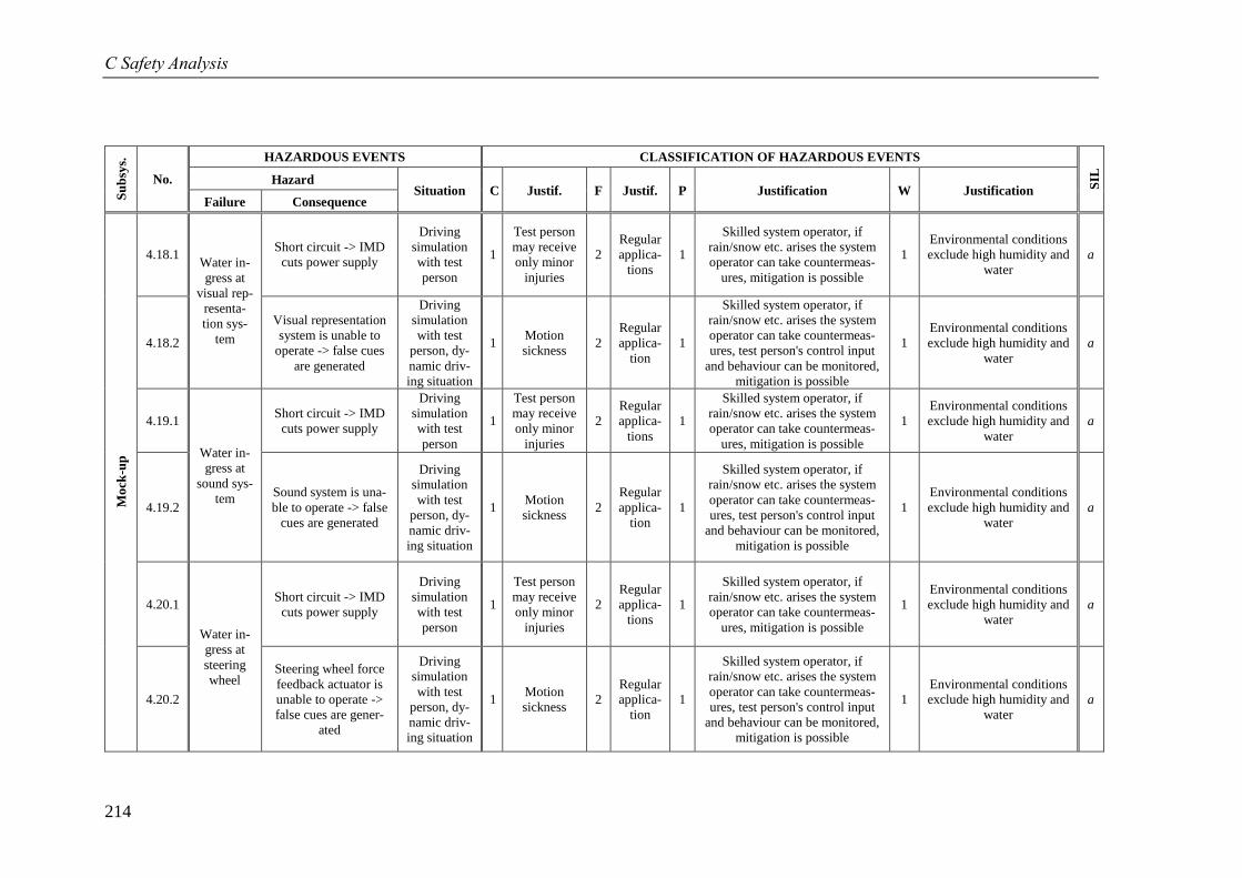
C Safety Analysis
214
Su
bsy
s.
No.
HAZARDOUS EVENTS CLASSIFICATION OF HAZARDOUS EVENTS
SIL
Hazard Situation C Justif. F Justif. P Justification W Justification
Failure Consequence
Mo
ck-u
p
4.18.1 Water in-
gress at
visual rep-
resenta-
tion sys-
tem
Short circuit -> IMD
cuts power supply
Driving
simulation
with test
person
1
Test person
may receive
only minor
injuries
2
Regular
applica-
tions
1
Skilled system operator, if
rain/snow etc. arises the system
operator can take countermeas-
ures, mitigation is possible
1
Environmental conditions
exclude high humidity and
water
a
4.18.2
Visual representation
system is unable to
operate -> false cues
are generated
Driving
simulation
with test
person, dy-
namic driv-
ing situation
1 Motion
sickness 2
Regular
applica-
tion
1
Skilled system operator, if
rain/snow etc. arises the system
operator can take countermeas-
ures, test person's control input
and behaviour can be monitored,
mitigation is possible
1
Environmental conditions
exclude high humidity and
water
a
4.19.1
Water in-
gress at
sound sys-
tem
Short circuit -> IMD
cuts power supply
Driving
simulation
with test
person
1
Test person
may receive
only minor
injuries
2
Regular
applica-
tions
1
Skilled system operator, if
rain/snow etc. arises the system
operator can take countermeas-
ures, mitigation is possible
1
Environmental conditions
exclude high humidity and
water
a
4.19.2
Sound system is una-
ble to operate -> false
cues are generated
Driving
simulation
with test
person, dy-
namic driv-
ing situation
1 Motion
sickness 2
Regular
applica-
tion
1
Skilled system operator, if
rain/snow etc. arises the system
operator can take countermeas-
ures, test person's control input
and behaviour can be monitored,
mitigation is possible
1
Environmental conditions
exclude high humidity and
water
a
4.20.1
Water in-
gress at
steering
wheel
Short circuit -> IMD
cuts power supply
Driving
simulation
with test
person
1
Test person
may receive
only minor
injuries
2
Regular
applica-
tions
1
Skilled system operator, if
rain/snow etc. arises the system
operator can take countermeas-
ures, mitigation is possible
1
Environmental conditions
exclude high humidity and
water
a
4.20.2
Steering wheel force
feedback actuator is
unable to operate ->
false cues are gener-
ated
Driving
simulation
with test
person, dy-
namic driv-
ing situation
1 Motion
sickness 2
Regular
applica-
tion
1
Skilled system operator, if
rain/snow etc. arises the system
operator can take countermeas-
ures, test person's control input
and behaviour can be monitored,
mitigation is possible
1
Environmental conditions
exclude high humidity and
water
a
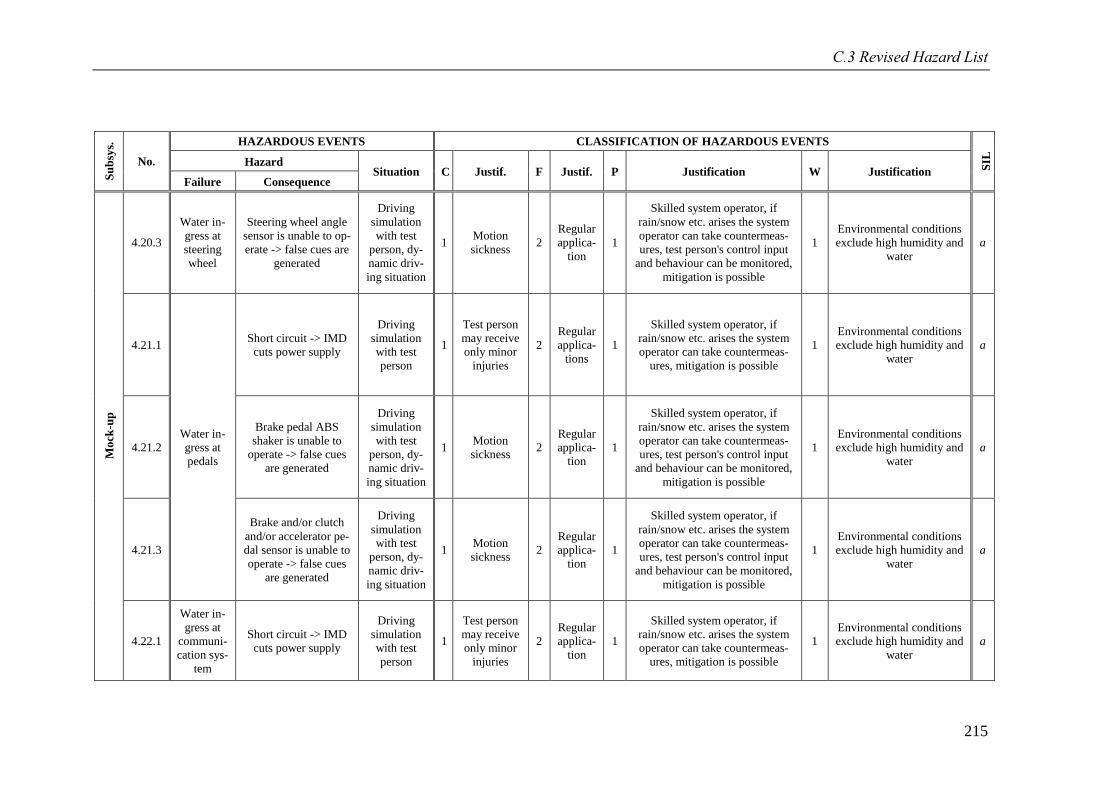
C.3 Revised Hazard List
215
Su
bsy
s.
No.
HAZARDOUS EVENTS CLASSIFICATION OF HAZARDOUS EVENTS
SIL
Hazard Situation C Justif. F Justif. P Justification W Justification
Failure Consequence
Mo
ck-u
p
4.20.3
Water in-
gress at
steering
wheel
Steering wheel angle
sensor is unable to op-
erate -> false cues are
generated
Driving
simulation
with test
person, dy-
namic driv-
ing situation
1 Motion
sickness 2
Regular
applica-
tion
1
Skilled system operator, if
rain/snow etc. arises the system
operator can take countermeas-
ures, test person's control input
and behaviour can be monitored,
mitigation is possible
1
Environmental conditions
exclude high humidity and
water
a
4.21.1
Water in-
gress at
pedals
Short circuit -> IMD
cuts power supply
Driving
simulation
with test
person
1
Test person
may receive
only minor
injuries
2
Regular
applica-
tions
1
Skilled system operator, if
rain/snow etc. arises the system
operator can take countermeas-
ures, mitigation is possible
1
Environmental conditions
exclude high humidity and
water
a
4.21.2
Brake pedal ABS
shaker is unable to
operate -> false cues
are generated
Driving
simulation
with test
person, dy-
namic driv-
ing situation
1 Motion
sickness 2
Regular
applica-
tion
1
Skilled system operator, if
rain/snow etc. arises the system
operator can take countermeas-
ures, test person's control input
and behaviour can be monitored,
mitigation is possible
1
Environmental conditions
exclude high humidity and
water
a
4.21.3
Brake and/or clutch
and/or accelerator pe-
dal sensor is unable to
operate -> false cues
are generated
Driving
simulation
with test
person, dy-
namic driv-
ing situation
1 Motion
sickness 2
Regular
applica-
tion
1
Skilled system operator, if
rain/snow etc. arises the system
operator can take countermeas-
ures, test person's control input
and behaviour can be monitored,
mitigation is possible
1
Environmental conditions
exclude high humidity and
water
a
4.22.1
Water in-
gress at
communi-
cation sys-
tem
Short circuit -> IMD
cuts power supply
Driving
simulation
with test
person
1
Test person
may receive
only minor
injuries
2
Regular
applica-
tion
1
Skilled system operator, if
rain/snow etc. arises the system
operator can take countermeas-
ures, mitigation is possible
1
Environmental conditions
exclude high humidity and
water
a
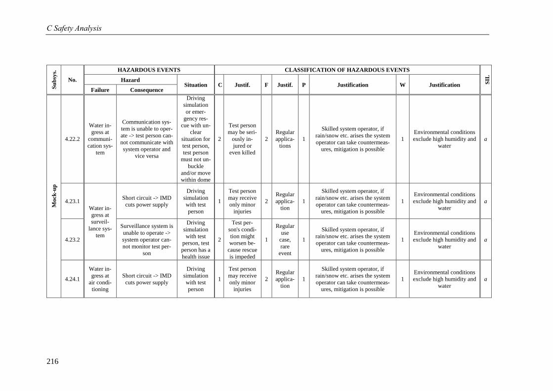
C Safety Analysis
216
Su
bsy
s.
No.
HAZARDOUS EVENTS CLASSIFICATION OF HAZARDOUS EVENTS
SIL
Hazard Situation C Justif. F Justif. P Justification W Justification
Failure Consequence
Mo
ck-u
p
4.22.2
Water in-
gress at
communi-
cation sys-
tem
Communication sys-
tem is unable to oper-
ate -> test person can-
not communicate with
system operator and
vice versa
Driving
simulation
or emer-
gency res-
cue with un-
clear
situation for
test person,
test person
must not un-
buckle
and/or move
within dome
2
Test person
may be seri-
ously in-
jured or
even killed
2
Regular
applica-
tions
1
Skilled system operator, if
rain/snow etc. arises the system
operator can take countermeas-
ures, mitigation is possible
1
Environmental conditions
exclude high humidity and
water
a
4.23.1
Water in-
gress at
surveil-
lance sys-
tem
Short circuit -> IMD
cuts power supply
Driving
simulation
with test
person
1
Test person
may receive
only minor
injuries
2
Regular
applica-
tion
1
Skilled system operator, if
rain/snow etc. arises the system
operator can take countermeas-
ures, mitigation is possible
1
Environmental conditions
exclude high humidity and
water
a
4.23.2
Surveillance system is
unable to operate ->
system operator can-
not monitor test per-
son
Driving
simulation
with test
person, test
person has a
health issue
2
Test per-
son's condi-
tion might
worsen be-
cause rescue
is impeded
1
Regular
use
case,
rare
event
1
Skilled system operator, if
rain/snow etc. arises the system
operator can take countermeas-
ures, mitigation is possible
1
Environmental conditions
exclude high humidity and
water
a
4.24.1
Water in-
gress at
air condi-
tioning
Short circuit -> IMD
cuts power supply
Driving
simulation
with test
person
1
Test person
may receive
only minor
injuries
2
Regular
applica-
tion
1
Skilled system operator, if
rain/snow etc. arises the system
operator can take countermeas-
ures, mitigation is possible
1
Environmental conditions
exclude high humidity and
water
a
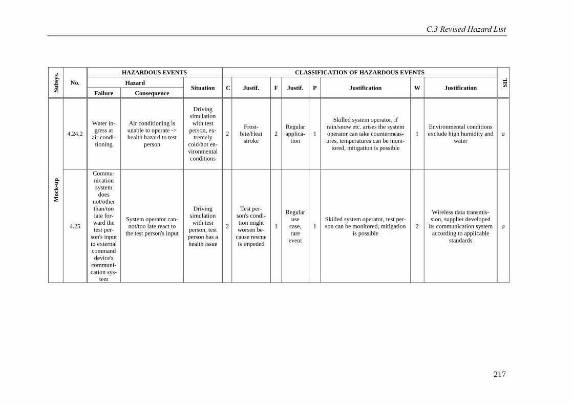
C.3 Revised Hazard List
217
Su
bsy
s.
No.
HAZARDOUS EVENTS CLASSIFICATION OF HAZARDOUS EVENTS
SIL
Hazard Situation C Justif. F Justif. P Justification W Justification
Failure Consequence
Mo
ck-u
p
4.24.2
Water in-
gress at
air condi-
tioning
Air conditioning is
unable to operate ->
health hazard to test
person
Driving
simulation
with test
person, ex-
tremely
cold/hot en-
vironmental
conditions
2
Frost-
bite/Heat
stroke
2
Regular
applica-
tion
1
Skilled system operator, if
rain/snow etc. arises the system
operator can take countermeas-
ures, temperatures can be moni-
tored, mitigation is possible
1
Environmental conditions
exclude high humidity and
water
a
4.25
Commu-
nication
system
does
not/other
than/too
late for-
ward the
test per-
son's input
to external
command
device's
communi-
cation sys-
tem
System operator can-
not/too late react to
the test person's input
Driving
simulation
with test
person, test
person has a
health issue
2
Test per-
son's condi-
tion might
worsen be-
cause rescue
is impeded
1
Regular
use
case,
rare
event
1
Skilled system operator, test per-
son can be monitored, mitigation
is possible
2
Wireless data transmis-
sion, supplier developed
its communication system
according to applicable
standards
a
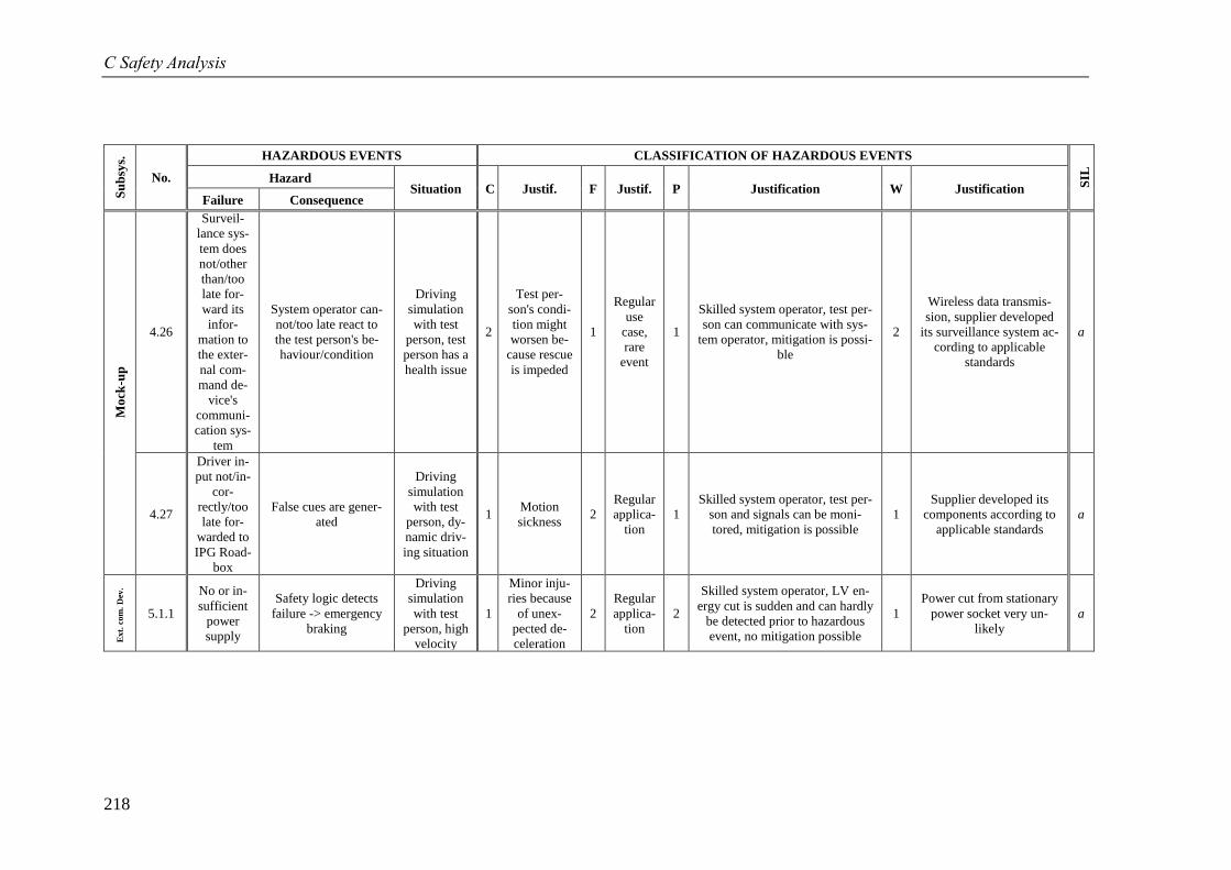
C Safety Analysis
218
Su
bsy
s.
No.
HAZARDOUS EVENTS CLASSIFICATION OF HAZARDOUS EVENTS
SIL
Hazard Situation C Justif. F Justif. P Justification W Justification
Failure Consequence
Mo
ck-u
p
4.26
Surveil-
lance sys-
tem does
not/other
than/too
late for-
ward its
infor-
mation to
the exter-
nal com-
mand de-
vice's
communi-
cation sys-
tem
System operator can-
not/too late react to
the test person's be-
haviour/condition
Driving
simulation
with test
person, test
person has a
health issue
2
Test per-
son's condi-
tion might
worsen be-
cause rescue
is impeded
1
Regular
use
case,
rare
event
1
Skilled system operator, test per-
son can communicate with sys-
tem operator, mitigation is possi-
ble
2
Wireless data transmis-
sion, supplier developed
its surveillance system ac-
cording to applicable
standards
a
4.27
Driver in-
put not/in-
cor-
rectly/too
late for-
warded to
IPG Road-
box
False cues are gener-
ated
Driving
simulation
with test
person, dy-
namic driv-
ing situation
1 Motion
sickness 2
Regular
applica-
tion
1
Skilled system operator, test per-
son and signals can be moni-
tored, mitigation is possible
1
Supplier developed its
components according to
applicable standards
a
Ext.
com
. D
ev.
5.1.1
No or in-
sufficient
power
supply
Safety logic detects
failure -> emergency
braking
Driving
simulation
with test
person, high
velocity
1
Minor inju-
ries because
of unex-
pected de-
celeration
2
Regular
applica-
tion
2
Skilled system operator, LV en-
ergy cut is sudden and can hardly
be detected prior to hazardous
event, no mitigation possible
1
Power cut from stationary
power socket very un-
likely
a
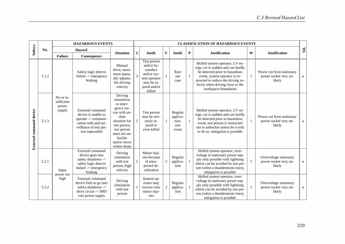
C.3 Revised Hazard List
219
Su
bsy
s.
No.
HAZARDOUS EVENTS CLASSIFICATION OF HAZARDOUS EVENTS
SIL
Hazard Situation C Justif. F Justif. P Justification W Justification
Failure Consequence
Ex
tern
al
com
ma
nd
dev
ice
5.1.2
No or in-
sufficient
power
supply
Safety logic detects
failure -> emergency
braking
Manual
drive, maxi-
mum manu-
ally adjusta-
ble driving
velocity
3
Test person
and/or by-
standers
and/or sys-
tem operator
may be in-
jured and/or
killed
1
Rare
use
case
1
Skilled system operator, LV en-
ergy cut is sudden and can hardly
be detected prior to hazardous
event, system operator is in-
structed to reduce the driving ve-
locity when driving close to the
workspace boundaries
1
Power cut from stationary
power socket very un-
likely
a
5.1.3
External command
device is unable to
operate -> communi-
cation with and sur-
veillance of test per-
son impossible
Driving
simulation
or emer-
gency res-
cue with un-
clear
situation for
test person,
test person
must not un-
buckle
and/or move
within dome
2
Test person
may be seri-
ously in-
jured or
even killed
1
Regular
applica-
tion,
rare
event
1
Skilled system operator, LV en-
ergy cut is sudden and can hardly
be detected prior to hazardous
event, test person is instructed
not to unbuckle unless he is told
to do so, mitigation is possible
1
Power cut from stationary
power socket very un-
likely
a
5.2.1
Input
power too
high
External command
device goes into
safety shutdown ->
safety logic detects
failure -> emergency
braking
Driving
simulation
with test
person, high
velocity
1
Minor inju-
ries because
of unex-
pected de-
celeration
2
Regular
applica-
tion
1
Skilled system operator, over-
voltage in stationary power sup-
ply only possible with lightning
which can be avoided by test per-
son (when a thunderstorm rises),
mitigation is possible
1
Overvoltage stationary
power socket very un-
likely
a
5.2.2
External command
device fails to go into
safety shutdown ->
short circuit -> IMD
cuts power supply
Driving
simulation
with test
person
1
System op-
erator may
receive only
minor inju-
ries
2
Regular
applica-
tion
1
Skilled system operator, over-
voltage in stationary power sup-
ply only possible with lightning
which can be avoided by test per-
son (when a thunderstorm rises),
mitigation is possible
1
Overvoltage stationary
power socket very un-
likely
a
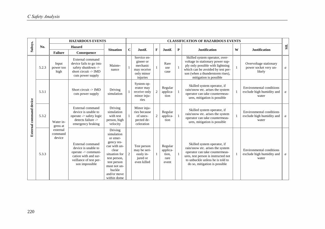
C Safety Analysis
220
Su
bsy
s.
No.
HAZARDOUS EVENTS CLASSIFICATION OF HAZARDOUS EVENTS
SIL
Hazard Situation C Justif. F Justif. P Justification W Justification
Failure Consequence
Ex
tern
al
com
ma
nd
dev
ice
5.2.3
Input
power too
high
External command
device fails to go into
safety shutdown ->
short circuit -> IMD
cuts power supply
Mainte-
nance 1
Service en-
gineer or
mechanic
may receive
only minor
injuries
1
Rare
use
case
1
Skilled system operator, over-
voltage in stationary power sup-
ply only possible with lightning
which can be avoided by test per-
son (when a thunderstorm rises),
mitigation is possible
1
Overvoltage stationary
power socket very un-
likely
a
5.3.1
Water in-
gress at
external
command
device
Short circuit -> IMD
cuts power supply
Driving
simulation 1
System op-
erator may
receive only
minor inju-
ries
2
Regular
applica-
tion
1
Skilled system operator, if
rain/snow etc. arises the system
operator can take countermeas-
ures, mitigation is possible
1
Environmental conditions
exclude high humidity and
water
a
5.3.2
External command
device is unable to
operate -> safety logic
detects failure ->
emergency braking
Driving
simulation
with test
person, high
velocity
1
Minor inju-
ries because
of unex-
pected de-
celeration
2
Regular
applica-
tion
1
Skilled system operator, if
rain/snow etc. arises the system
operator can take countermeas-
ures, mitigation is possible
1
Environmental conditions
exclude high humidity and
water
a
5.3.3
External command
device is unable to
operate -> communi-
cation with and sur-
veillance of test per-
son impossible
Driving
simulation
or emer-
gency res-
cue with un-
clear
situation for
test person,
test person
must not un-
buckle
and/or move
within dome
2
Test person
may be seri-
ously in-
jured or
even killed
1
Regular
applica-
tion,
rare
event
1
Skilled system operator, if
rain/snow etc. arises the system
operator can take countermeas-
ures, test person is instructed not
to unbuckle unless he is told to
do so, mitigation is possible
1
Environmental conditions
exclude high humidity and
water
a
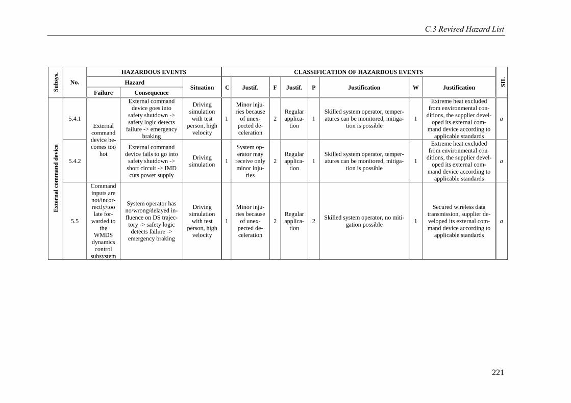
C.3 Revised Hazard List
221
Su
bsy
s.
No.
HAZARDOUS EVENTS CLASSIFICATION OF HAZARDOUS EVENTS
SIL
Hazard Situation C Justif. F Justif. P Justification W Justification
Failure Consequence
Ex
tern
al
com
ma
nd
dev
ice
5.4.1
External
command
device be-
comes too
hot
External command
device goes into
safety shutdown ->
safety logic detects
failure -> emergency
braking
Driving
simulation
with test
person, high
velocity
1
Minor inju-
ries because
of unex-
pected de-
celeration
2
Regular
applica-
tion
1
Skilled system operator, temper-
atures can be monitored, mitiga-
tion is possible
1
Extreme heat excluded
from environmental con-
ditions, the supplier devel-
oped its external com-
mand device according to
applicable standards
a
5.4.2
External command
device fails to go into
safety shutdown ->
short circuit -> IMD
cuts power supply
Driving
simulation 1
System op-
erator may
receive only
minor inju-
ries
2
Regular
applica-
tion
1
Skilled system operator, temper-
atures can be monitored, mitiga-
tion is possible
1
Extreme heat excluded
from environmental con-
ditions, the supplier devel-
oped its external com-
mand device according to
applicable standards
a
5.5
Command
inputs are
not/incor-
rectly/too
late for-
warded to
the
WMDS
dynamics
control
subsystem
System operator has
no/wrong/delayed in-
fluence on DS trajec-
tory -> safety logic
detects failure ->
emergency braking
Driving
simulation
with test
person, high
velocity
1
Minor inju-
ries because
of unex-
pected de-
celeration
2
Regular
applica-
tion
2 Skilled system operator, no miti-
gation possible 1
Secured wireless data
transmission, supplier de-
veloped its external com-
mand device according to
applicable standards
a
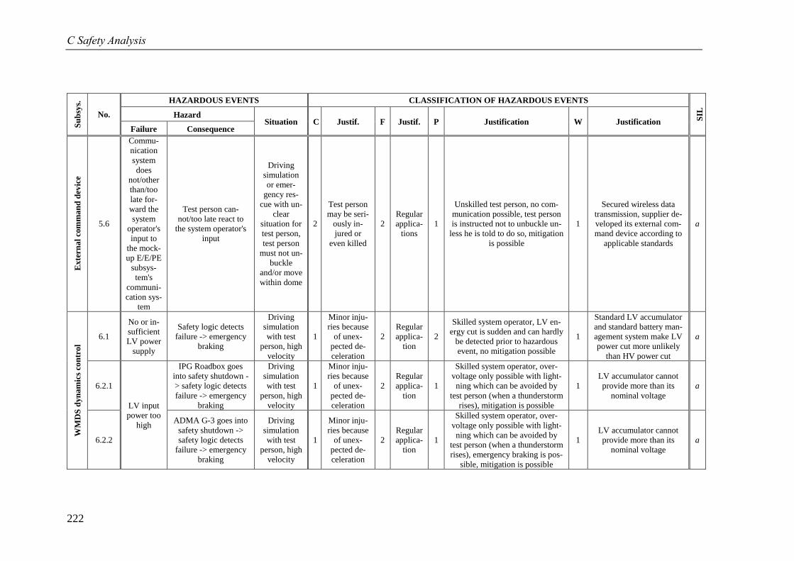
C Safety Analysis
222
Su
bsy
s.
No.
HAZARDOUS EVENTS CLASSIFICATION OF HAZARDOUS EVENTS
SIL
Hazard Situation C Justif. F Justif. P Justification W Justification
Failure Consequence
Ex
tern
al
com
ma
nd
dev
ice
5.6
Commu-
nication
system
does
not/other
than/too
late for-
ward the
system
operator's
input to
the mock-
up E/E/PE
subsys-
tem's
communi-
cation sys-
tem
Test person can-
not/too late react to
the system operator's
input
Driving
simulation
or emer-
gency res-
cue with un-
clear
situation for
test person,
test person
must not un-
buckle
and/or move
within dome
2
Test person
may be seri-
ously in-
jured or
even killed
2
Regular
applica-
tions
1
Unskilled test person, no com-
munication possible, test person
is instructed not to unbuckle un-
less he is told to do so, mitigation
is possible
1
Secured wireless data
transmission, supplier de-
veloped its external com-
mand device according to
applicable standards
a
WM
DS
dyn
am
ics
con
tro
l
6.1
No or in-
sufficient
LV power
supply
Safety logic detects
failure -> emergency
braking
Driving
simulation
with test
person, high
velocity
1
Minor inju-
ries because
of unex-
pected de-
celeration
2
Regular
applica-
tion
2
Skilled system operator, LV en-
ergy cut is sudden and can hardly
be detected prior to hazardous
event, no mitigation possible
1
Standard LV accumulator
and standard battery man-
agement system make LV
power cut more unlikely
than HV power cut
a
6.2.1
LV input
power too
high
IPG Roadbox goes
into safety shutdown -
> safety logic detects
failure -> emergency
braking
Driving
simulation
with test
person, high
velocity
1
Minor inju-
ries because
of unex-
pected de-
celeration
2
Regular
applica-
tion
1
Skilled system operator, over-
voltage only possible with light-
ning which can be avoided by
test person (when a thunderstorm
rises), mitigation is possible
1
LV accumulator cannot
provide more than its
nominal voltage
a
6.2.2
ADMA G-3 goes into
safety shutdown ->
safety logic detects
failure -> emergency
braking
Driving
simulation
with test
person, high
velocity
1
Minor inju-
ries because
of unex-
pected de-
celeration
2
Regular
applica-
tion
1
Skilled system operator, over-
voltage only possible with light-
ning which can be avoided by
test person (when a thunderstorm
rises), emergency braking is pos-
sible, mitigation is possible
1
LV accumulator cannot
provide more than its
nominal voltage
a
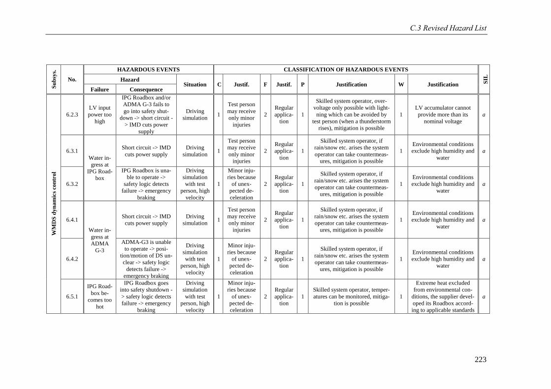
C.3 Revised Hazard List
223
Su
bsy
s.
No.
HAZARDOUS EVENTS CLASSIFICATION OF HAZARDOUS EVENTS
SIL
Hazard Situation C Justif. F Justif. P Justification W Justification
Failure Consequence
WM
DS
dyn
am
ics
con
tro
l
6.2.3
LV input
power too
high
IPG Roadbox and/or
ADMA G-3 fails to
go into safety shut-
down -> short circuit -
> IMD cuts power
supply
Driving
simulation 1
Test person
may receive
only minor
injuries
2
Regular
applica-
tion
1
Skilled system operator, over-
voltage only possible with light-
ning which can be avoided by
test person (when a thunderstorm
rises), mitigation is possible
1
LV accumulator cannot
provide more than its
nominal voltage
a
6.3.1
Water in-
gress at
IPG Road-
box
Short circuit -> IMD
cuts power supply
Driving
simulation 1
Test person
may receive
only minor
injuries
2
Regular
applica-
tion
1
Skilled system operator, if
rain/snow etc. arises the system
operator can take countermeas-
ures, mitigation is possible
1
Environmental conditions
exclude high humidity and
water
a
6.3.2
IPG Roadbox is una-
ble to operate ->
safety logic detects
failure -> emergency
braking
Driving
simulation
with test
person, high
velocity
1
Minor inju-
ries because
of unex-
pected de-
celeration
2
Regular
applica-
tion
1
Skilled system operator, if
rain/snow etc. arises the system
operator can take countermeas-
ures, mitigation is possible
1
Environmental conditions
exclude high humidity and
water
a
6.4.1
Water in-
gress at
ADMA
G-3
Short circuit -> IMD
cuts power supply
Driving
simulation 1
Test person
may receive
only minor
injuries
2
Regular
applica-
tion
1
Skilled system operator, if
rain/snow etc. arises the system
operator can take countermeas-
ures, mitigation is possible
1
Environmental conditions
exclude high humidity and
water
a
6.4.2
ADMA-G3 is unable
to operate -> posi-
tion/motion of DS un-
clear -> safety logic
detects failure ->
emergency braking
Driving
simulation
with test
person, high
velocity
1
Minor inju-
ries because
of unex-
pected de-
celeration
2
Regular
applica-
tion
1
Skilled system operator, if
rain/snow etc. arises the system
operator can take countermeas-
ures, mitigation is possible
1
Environmental conditions
exclude high humidity and
water
a
6.5.1
IPG Road-
box be-
comes too
hot
IPG Roadbox goes
into safety shutdown -
> safety logic detects
failure -> emergency
braking
Driving
simulation
with test
person, high
velocity
1
Minor inju-
ries because
of unex-
pected de-
celeration
2
Regular
applica-
tion
1
Skilled system operator, temper-
atures can be monitored, mitiga-
tion is possible
1
Extreme heat excluded
from environmental con-
ditions, the supplier devel-
oped its Roadbox accord-
ing to applicable standards
a
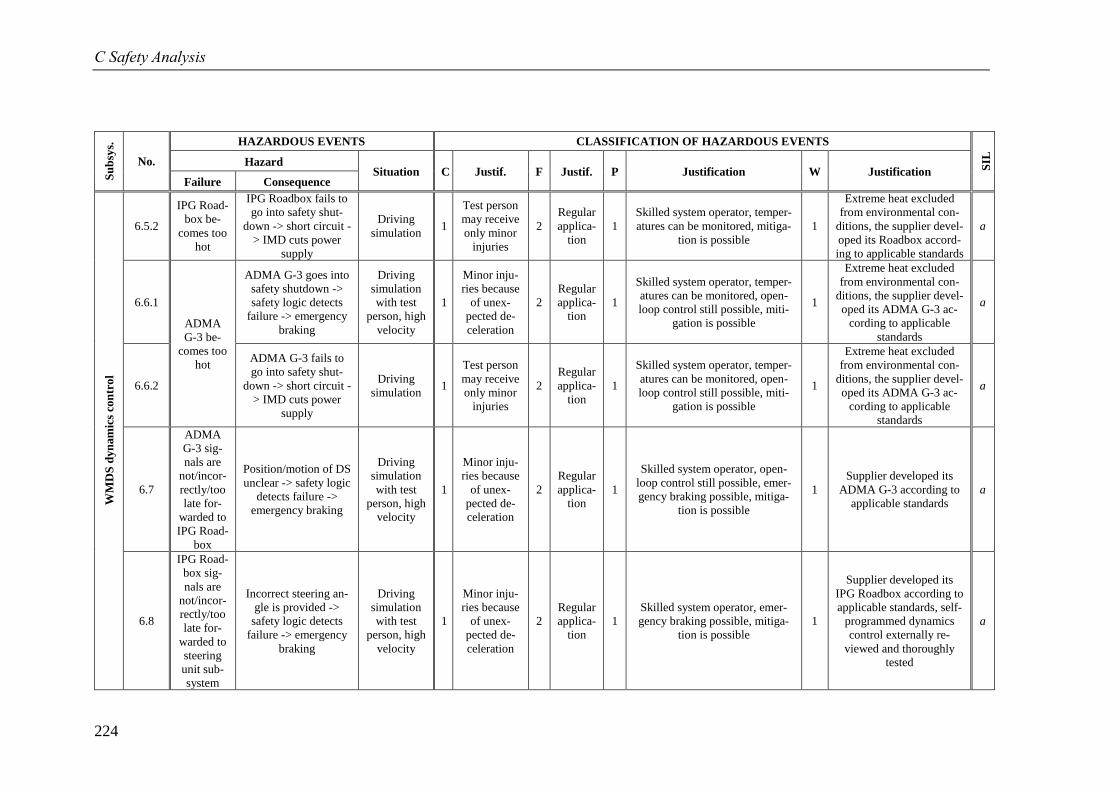
C Safety Analysis
224
Su
bsy
s.
No.
HAZARDOUS EVENTS CLASSIFICATION OF HAZARDOUS EVENTS
SIL
Hazard Situation C Justif. F Justif. P Justification W Justification
Failure Consequence
WM
DS
dyn
am
ics
con
tro
l
6.5.2
IPG Road-
box be-
comes too
hot
IPG Roadbox fails to
go into safety shut-
down -> short circuit -
> IMD cuts power
supply
Driving
simulation 1
Test person
may receive
only minor
injuries
2
Regular
applica-
tion
1
Skilled system operator, temper-
atures can be monitored, mitiga-
tion is possible
1
Extreme heat excluded
from environmental con-
ditions, the supplier devel-
oped its Roadbox accord-
ing to applicable standards
a
6.6.1
ADMA
G-3 be-
comes too
hot
ADMA G-3 goes into
safety shutdown ->
safety logic detects
failure -> emergency
braking
Driving
simulation
with test
person, high
velocity
1
Minor inju-
ries because
of unex-
pected de-
celeration
2
Regular
applica-
tion
1
Skilled system operator, temper-
atures can be monitored, open-
loop control still possible, miti-
gation is possible
1
Extreme heat excluded
from environmental con-
ditions, the supplier devel-
oped its ADMA G-3 ac-
cording to applicable
standards
a
6.6.2
ADMA G-3 fails to
go into safety shut-
down -> short circuit -
> IMD cuts power
supply
Driving
simulation 1
Test person
may receive
only minor
injuries
2
Regular
applica-
tion
1
Skilled system operator, temper-
atures can be monitored, open-
loop control still possible, miti-
gation is possible
1
Extreme heat excluded
from environmental con-
ditions, the supplier devel-
oped its ADMA G-3 ac-
cording to applicable
standards
a
6.7
ADMA
G-3 sig-
nals are
not/incor-
rectly/too
late for-
warded to
IPG Road-
box
Position/motion of DS
unclear -> safety logic
detects failure ->
emergency braking
Driving
simulation
with test
person, high
velocity
1
Minor inju-
ries because
of unex-
pected de-
celeration
2
Regular
applica-
tion
1
Skilled system operator, open-
loop control still possible, emer-
gency braking possible, mitiga-
tion is possible
1
Supplier developed its
ADMA G-3 according to
applicable standards
a
6.8
IPG Road-
box sig-
nals are
not/incor-
rectly/too
late for-
warded to
steering
unit sub-
system
Incorrect steering an-
gle is provided ->
safety logic detects
failure -> emergency
braking
Driving
simulation
with test
person, high
velocity
1
Minor inju-
ries because
of unex-
pected de-
celeration
2
Regular
applica-
tion
1
Skilled system operator, emer-
gency braking possible, mitiga-
tion is possible
1
Supplier developed its
IPG Roadbox according to
applicable standards, self-
programmed dynamics
control externally re-
viewed and thoroughly
tested
a
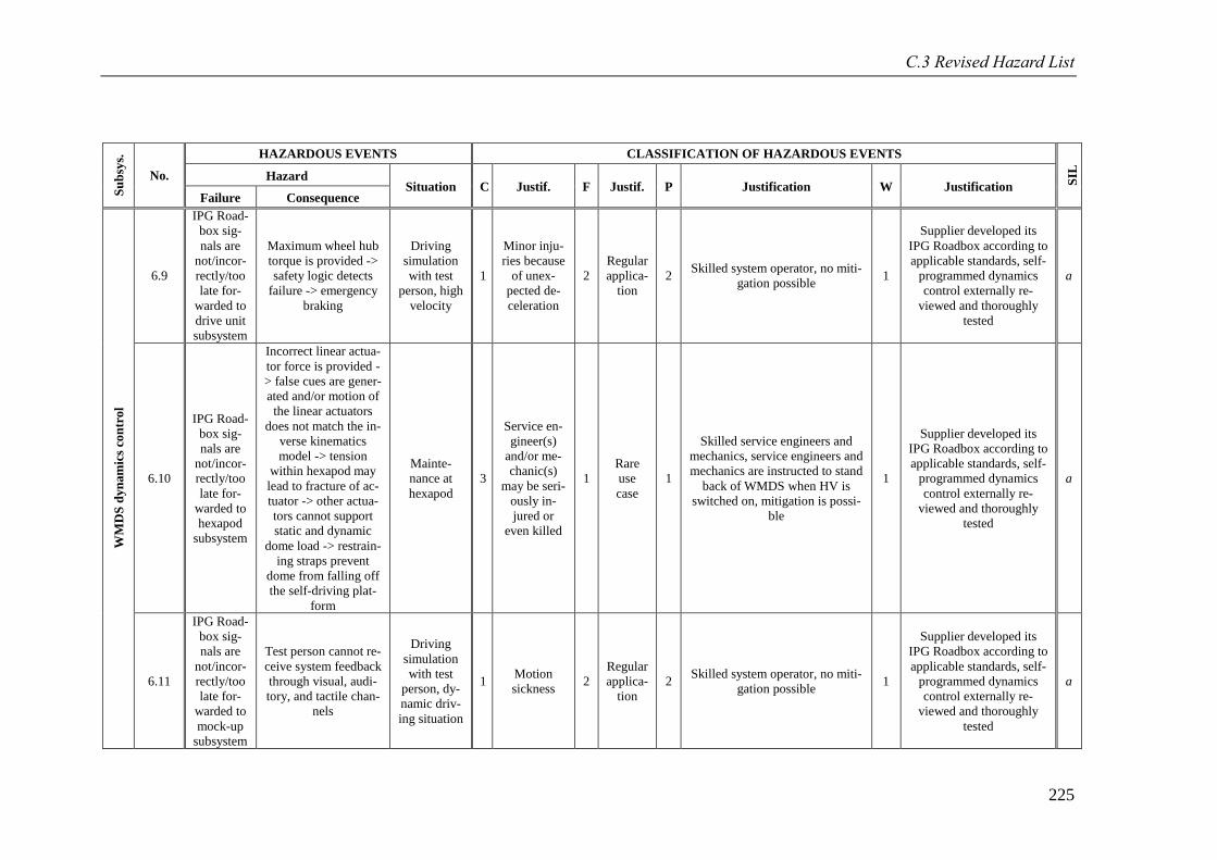
C.3 Revised Hazard List
225
Su
bsy
s.
No.
HAZARDOUS EVENTS CLASSIFICATION OF HAZARDOUS EVENTS
SIL
Hazard Situation C Justif. F Justif. P Justification W Justification
Failure Consequence
WM
DS
dyn
am
ics
con
tro
l
6.9
IPG Road-
box sig-
nals are
not/incor-
rectly/too
late for-
warded to
drive unit
subsystem
Maximum wheel hub
torque is provided ->
safety logic detects
failure -> emergency
braking
Driving
simulation
with test
person, high
velocity
1
Minor inju-
ries because
of unex-
pected de-
celeration
2
Regular
applica-
tion
2 Skilled system operator, no miti-
gation possible 1
Supplier developed its
IPG Roadbox according to
applicable standards, self-
programmed dynamics
control externally re-
viewed and thoroughly
tested
a
6.10
IPG Road-
box sig-
nals are
not/incor-
rectly/too
late for-
warded to
hexapod
subsystem
Incorrect linear actua-
tor force is provided -
> false cues are gener-
ated and/or motion of
the linear actuators
does not match the in-
verse kinematics
model -> tension
within hexapod may
lead to fracture of ac-
tuator -> other actua-
tors cannot support
static and dynamic
dome load -> restrain-
ing straps prevent
dome from falling off
the self-driving plat-
form
Mainte-
nance at
hexapod
3
Service en-
gineer(s)
and/or me-
chanic(s)
may be seri-
ously in-
jured or
even killed
1
Rare
use
case
1
Skilled service engineers and
mechanics, service engineers and
mechanics are instructed to stand
back of WMDS when HV is
switched on, mitigation is possi-
ble
1
Supplier developed its
IPG Roadbox according to
applicable standards, self-
programmed dynamics
control externally re-
viewed and thoroughly
tested
a
6.11
IPG Road-
box sig-
nals are
not/incor-
rectly/too
late for-
warded to
mock-up
subsystem
Test person cannot re-
ceive system feedback
through visual, audi-
tory, and tactile chan-
nels
Driving
simulation
with test
person, dy-
namic driv-
ing situation
1 Motion
sickness 2
Regular
applica-
tion
2 Skilled system operator, no miti-
gation possible 1
Supplier developed its
IPG Roadbox according to
applicable standards, self-
programmed dynamics
control externally re-
viewed and thoroughly
tested
a
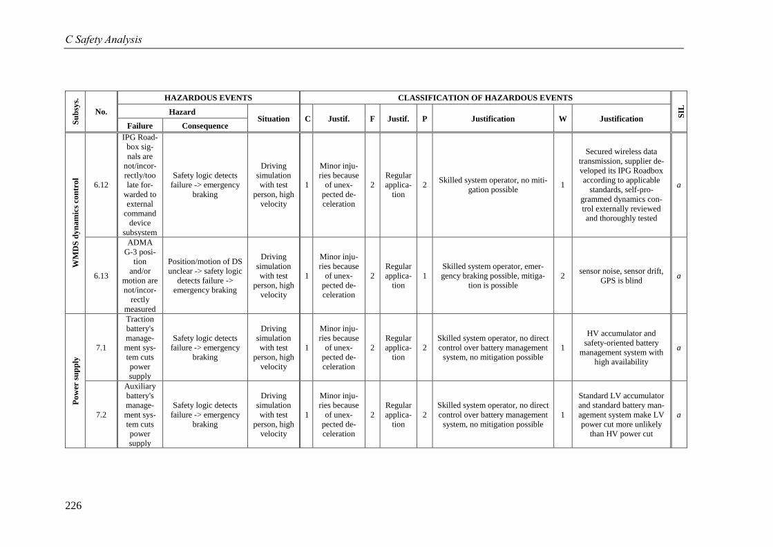
C Safety Analysis
226
Su
bsy
s.
No.
HAZARDOUS EVENTS CLASSIFICATION OF HAZARDOUS EVENTS
SIL
Hazard Situation C Justif. F Justif. P Justification W Justification
Failure Consequence
WM
DS
dyn
am
ics
con
tro
l
6.12
IPG Road-
box sig-
nals are
not/incor-
rectly/too
late for-
warded to
external
command
device
subsystem
Safety logic detects
failure -> emergency
braking
Driving
simulation
with test
person, high
velocity
1
Minor inju-
ries because
of unex-
pected de-
celeration
2
Regular
applica-
tion
2 Skilled system operator, no miti-
gation possible 1
Secured wireless data
transmission, supplier de-
veloped its IPG Roadbox
according to applicable
standards, self-pro-
grammed dynamics con-
trol externally reviewed
and thoroughly tested
a
6.13
ADMA
G-3 posi-
tion
and/or
motion are
not/incor-
rectly
measured
Position/motion of DS
unclear -> safety logic
detects failure ->
emergency braking
Driving
simulation
with test
person, high
velocity
1
Minor inju-
ries because
of unex-
pected de-
celeration
2
Regular
applica-
tion
1
Skilled system operator, emer-
gency braking possible, mitiga-
tion is possible
2 sensor noise, sensor drift,
GPS is blind a
Po
wer
su
pp
ly
7.1
Traction
battery's
manage-
ment sys-
tem cuts
power
supply
Safety logic detects
failure -> emergency
braking
Driving
simulation
with test
person, high
velocity
1
Minor inju-
ries because
of unex-
pected de-
celeration
2
Regular
applica-
tion
2
Skilled system operator, no direct
control over battery management
system, no mitigation possible
1
HV accumulator and
safety-oriented battery
management system with
high availability
a
7.2
Auxiliary
battery's
manage-
ment sys-
tem cuts
power
supply
Safety logic detects
failure -> emergency
braking
Driving
simulation
with test
person, high
velocity
1
Minor inju-
ries because
of unex-
pected de-
celeration
2
Regular
applica-
tion
2
Skilled system operator, no direct
control over battery management
system, no mitigation possible
1
Standard LV accumulator
and standard battery man-
agement system make LV
power cut more unlikely
than HV power cut
a
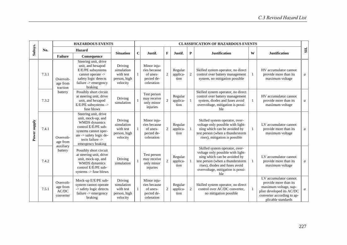
C.3 Revised Hazard List
227
Su
bsy
s.
No.
HAZARDOUS EVENTS CLASSIFICATION OF HAZARDOUS EVENTS
SIL
Hazard Situation C Justif. F Justif. P Justification W Justification
Failure Consequence
Po
wer
su
pp
ly
7.3.1
Overvolt-
age from
traction
battery
Steering unit, drive
unit, and hexapod
E/E/PE subsystems
cannot operate ->
safety logic detects
failure -> emergency
braking
Driving
simulation
with test
person, high
velocity
1
Minor inju-
ries because
of unex-
pected de-
celeration
2
Regular
applica-
tion
2
Skilled system operator, no direct
control over battery management
system, no mitigation possible
1
HV accumulator cannot
provide more than its
maximum voltage
a
7.3.2
Possibly short circuit
at steering unit, drive
unit, and hexapod
E/E/PE subsystems ->
fuse blows
Driving
simulation 1
Test person
may receive
only minor
injuries
2
Regular
applica-
tion
1
Skilled system operator, no direct
control over battery management
system, diodes and fuses avoid
overvoltage, mitigation is possi-
ble
1
HV accumulator cannot
provide more than its
maximum voltage
a
7.4.1
Overvolt-
age from
auxiliary
battery
Steering unit, drive
unit, mock-up, and
WMDS dynamics
control E/E/PE sub-
systems cannot oper-
ate -> safety logic de-
tects failure ->
emergency braking
Driving
simulation
with test
person, high
velocity
1
Minor inju-
ries because
of unex-
pected de-
celeration
2
Regular
applica-
tion
1
Skilled system operator, over-
voltage only possible with light-
ning which can be avoided by
test person (when a thunderstorm
rises), mitigation is possible
1
LV accumulator cannot
provide more than its
maximum voltage
a
7.4.2
Possibly short circuit
at steering unit, drive
unit, mock-up, and
WMDS dynamics
control E/E/PE sub-
systems -> fuse blows
Driving
simulation 1
Test person
may receive
only minor
injuries
2
Regular
applica-
tion
1
Skilled system operator, over-
voltage only possible with light-
ning which can be avoided by
test person (when a thunderstorm
rises), diodes and fuses avoid
overvoltage, mitigation is possi-
ble
1
LV accumulator cannot
provide more than its
maximum voltage
a
7.5.1
Overvolt-
age from
AC/DC
converter
Mock-up E/E/PE sub-
system cannot operate
-> safety logic detects
failure -> emergency
braking
Driving
simulation
with test
person, high
velocity
1
Minor inju-
ries because
of unex-
pected de-
celeration
2
Regular
applica-
tion
2
Skilled system operator, no direct
control over AC/DC converter,
no mitigation possible
1
LV accumulator cannot
provide more than its
maximum voltage, sup-
plier developed its AC/DC
converter according to ap-
plicable standards
a
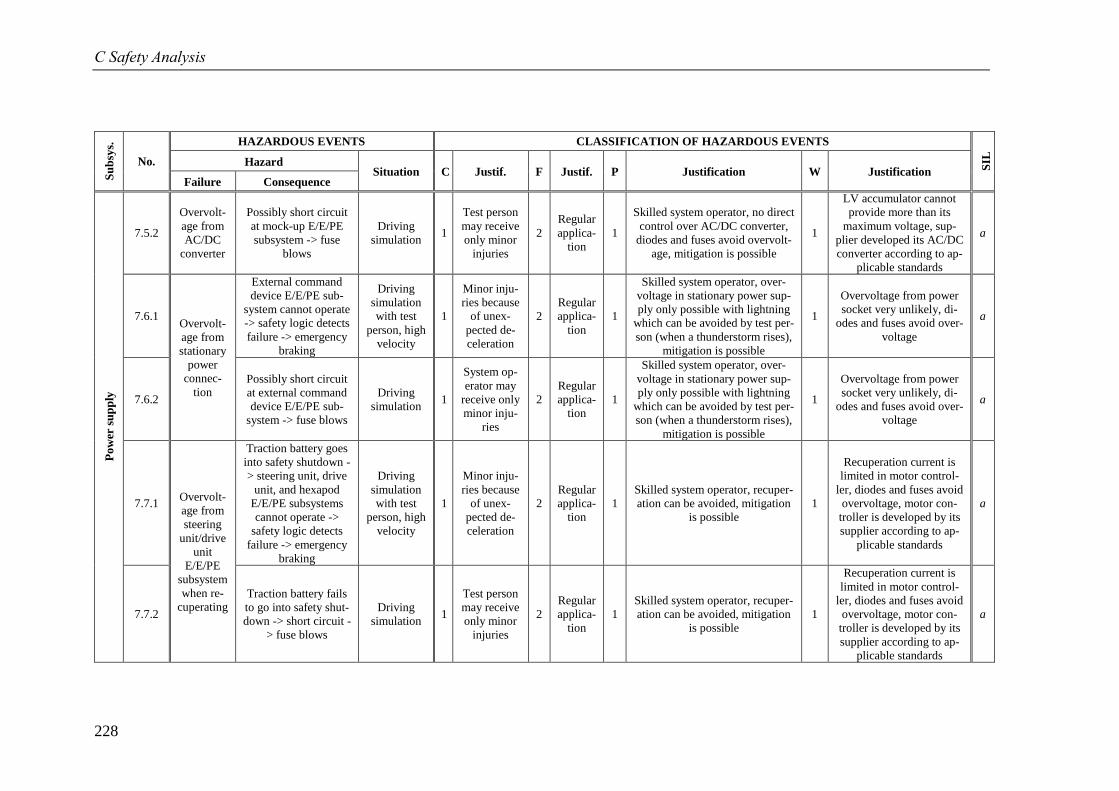
C Safety Analysis
228
Su
bsy
s.
No.
HAZARDOUS EVENTS CLASSIFICATION OF HAZARDOUS EVENTS
SIL
Hazard Situation C Justif. F Justif. P Justification W Justification
Failure Consequence
Po
wer
su
pp
ly
7.5.2
Overvolt-
age from
AC/DC
converter
Possibly short circuit
at mock-up E/E/PE
subsystem -> fuse
blows
Driving
simulation 1
Test person
may receive
only minor
injuries
2
Regular
applica-
tion
1
Skilled system operator, no direct
control over AC/DC converter,
diodes and fuses avoid overvolt-
age, mitigation is possible
1
LV accumulator cannot
provide more than its
maximum voltage, sup-
plier developed its AC/DC
converter according to ap-
plicable standards
a
7.6.1 Overvolt-
age from
stationary
power
connec-
tion
External command
device E/E/PE sub-
system cannot operate
-> safety logic detects
failure -> emergency
braking
Driving
simulation
with test
person, high
velocity
1
Minor inju-
ries because
of unex-
pected de-
celeration
2
Regular
applica-
tion
1
Skilled system operator, over-
voltage in stationary power sup-
ply only possible with lightning
which can be avoided by test per-
son (when a thunderstorm rises),
mitigation is possible
1
Overvoltage from power
socket very unlikely, di-
odes and fuses avoid over-
voltage
a
7.6.2
Possibly short circuit
at external command
device E/E/PE sub-
system -> fuse blows
Driving
simulation 1
System op-
erator may
receive only
minor inju-
ries
2
Regular
applica-
tion
1
Skilled system operator, over-
voltage in stationary power sup-
ply only possible with lightning
which can be avoided by test per-
son (when a thunderstorm rises),
mitigation is possible
1
Overvoltage from power
socket very unlikely, di-
odes and fuses avoid over-
voltage
a
7.7.1 Overvolt-
age from
steering
unit/drive
unit
E/E/PE
subsystem
when re-
cuperating
Traction battery goes
into safety shutdown -
> steering unit, drive
unit, and hexapod
E/E/PE subsystems
cannot operate ->
safety logic detects
failure -> emergency
braking
Driving
simulation
with test
person, high
velocity
1
Minor inju-
ries because
of unex-
pected de-
celeration
2
Regular
applica-
tion
1
Skilled system operator, recuper-
ation can be avoided, mitigation
is possible
1
Recuperation current is
limited in motor control-
ler, diodes and fuses avoid
overvoltage, motor con-
troller is developed by its
supplier according to ap-
plicable standards
a
7.7.2
Traction battery fails
to go into safety shut-
down -> short circuit -
> fuse blows
Driving
simulation 1
Test person
may receive
only minor
injuries
2
Regular
applica-
tion
1
Skilled system operator, recuper-
ation can be avoided, mitigation
is possible
1
Recuperation current is
limited in motor control-
ler, diodes and fuses avoid
overvoltage, motor con-
troller is developed by its
supplier according to ap-
plicable standards
a
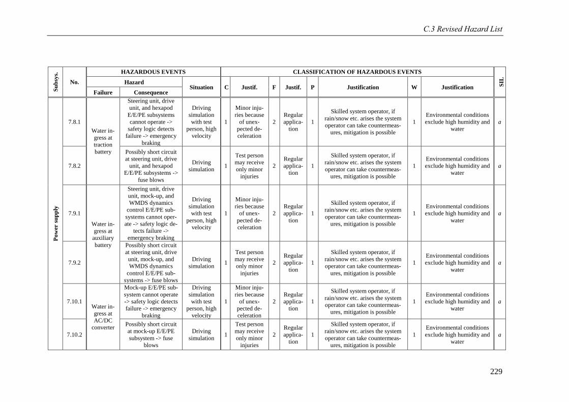
C.3 Revised Hazard List
229
Su
bsy
s.
No.
HAZARDOUS EVENTS CLASSIFICATION OF HAZARDOUS EVENTS
SIL
Hazard Situation C Justif. F Justif. P Justification W Justification
Failure Consequence
Po
wer
su
pp
ly
7.8.1
Water in-
gress at
traction
battery
Steering unit, drive
unit, and hexapod
E/E/PE subsystems
cannot operate ->
safety logic detects
failure -> emergency
braking
Driving
simulation
with test
person, high
velocity
1
Minor inju-
ries because
of unex-
pected de-
celeration
2
Regular
applica-
tion
1
Skilled system operator, if
rain/snow etc. arises the system
operator can take countermeas-
ures, mitigation is possible
1
Environmental conditions
exclude high humidity and
water
a
7.8.2
Possibly short circuit
at steering unit, drive
unit, and hexapod
E/E/PE subsystems ->
fuse blows
Driving
simulation 1
Test person
may receive
only minor
injuries
2
Regular
applica-
tion
1
Skilled system operator, if
rain/snow etc. arises the system
operator can take countermeas-
ures, mitigation is possible
1
Environmental conditions
exclude high humidity and
water
a
7.9.1
Water in-
gress at
auxiliary
battery
Steering unit, drive
unit, mock-up, and
WMDS dynamics
control E/E/PE sub-
systems cannot oper-
ate -> safety logic de-
tects failure ->
emergency braking
Driving
simulation
with test
person, high
velocity
1
Minor inju-
ries because
of unex-
pected de-
celeration
2
Regular
applica-
tion
1
Skilled system operator, if
rain/snow etc. arises the system
operator can take countermeas-
ures, mitigation is possible
1
Environmental conditions
exclude high humidity and
water
a
7.9.2
Possibly short circuit
at steering unit, drive
unit, mock-up, and
WMDS dynamics
control E/E/PE sub-
systems -> fuse blows
Driving
simulation 1
Test person
may receive
only minor
injuries
2
Regular
applica-
tion
1
Skilled system operator, if
rain/snow etc. arises the system
operator can take countermeas-
ures, mitigation is possible
1
Environmental conditions
exclude high humidity and
water
a
7.10.1 Water in-
gress at
AC/DC
converter
Mock-up E/E/PE sub-
system cannot operate
-> safety logic detects
failure -> emergency
braking
Driving
simulation
with test
person, high
velocity
1
Minor inju-
ries because
of unex-
pected de-
celeration
2
Regular
applica-
tion
1
Skilled system operator, if
rain/snow etc. arises the system
operator can take countermeas-
ures, mitigation is possible
1
Environmental conditions
exclude high humidity and
water
a
7.10.2
Possibly short circuit
at mock-up E/E/PE
subsystem -> fuse
blows
Driving
simulation 1
Test person
may receive
only minor
injuries
2
Regular
applica-
tion
1
Skilled system operator, if
rain/snow etc. arises the system
operator can take countermeas-
ures, mitigation is possible
1
Environmental conditions
exclude high humidity and
water
a
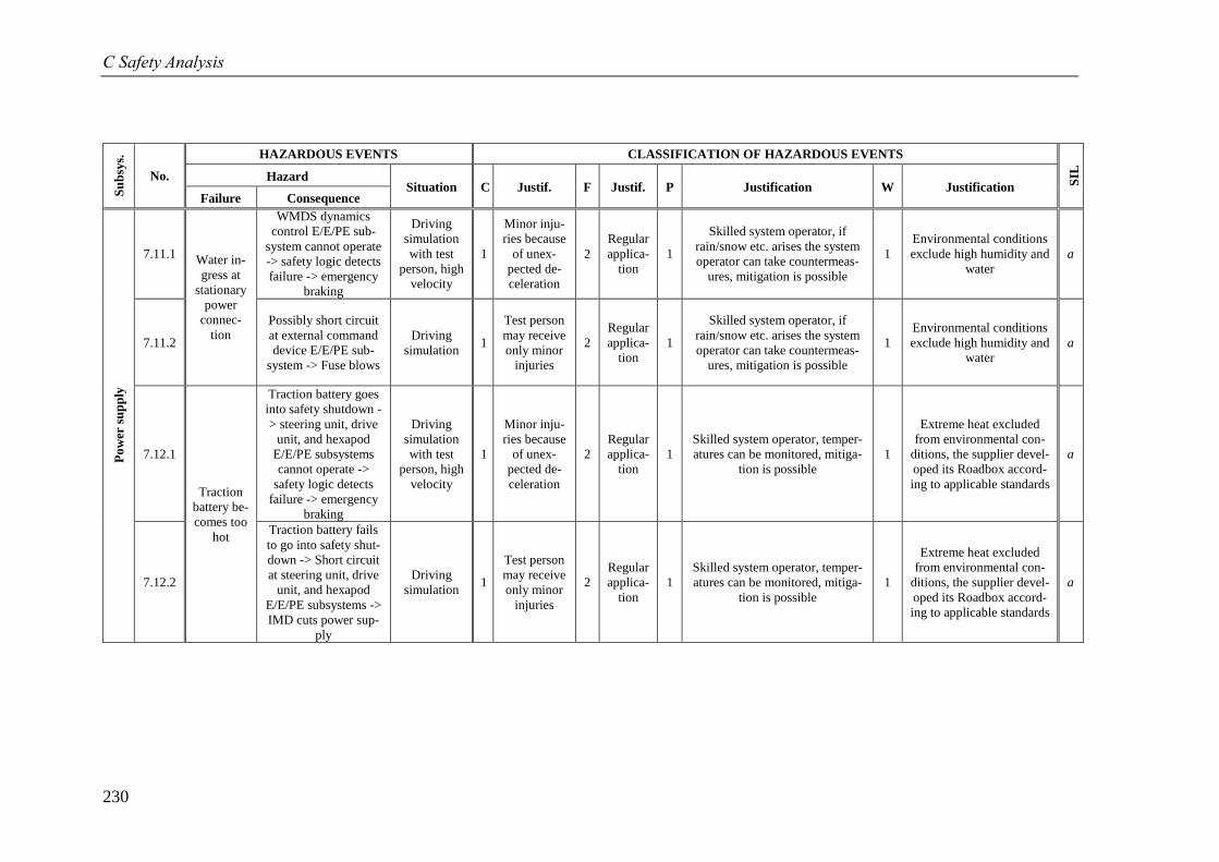
C Safety Analysis
230
Su
bsy
s.
No.
HAZARDOUS EVENTS CLASSIFICATION OF HAZARDOUS EVENTS
SIL
Hazard Situation C Justif. F Justif. P Justification W Justification
Failure Consequence
Po
wer
su
pp
ly
7.11.1 Water in-
gress at
stationary
power
connec-
tion
WMDS dynamics
control E/E/PE sub-
system cannot operate
-> safety logic detects
failure -> emergency
braking
Driving
simulation
with test
person, high
velocity
1
Minor inju-
ries because
of unex-
pected de-
celeration
2
Regular
applica-
tion
1
Skilled system operator, if
rain/snow etc. arises the system
operator can take countermeas-
ures, mitigation is possible
1
Environmental conditions
exclude high humidity and
water
a
7.11.2
Possibly short circuit
at external command
device E/E/PE sub-
system -> Fuse blows
Driving
simulation 1
Test person
may receive
only minor
injuries
2
Regular
applica-
tion
1
Skilled system operator, if
rain/snow etc. arises the system
operator can take countermeas-
ures, mitigation is possible
1
Environmental conditions
exclude high humidity and
water
a
7.12.1
Traction
battery be-
comes too
hot
Traction battery goes
into safety shutdown -
> steering unit, drive
unit, and hexapod
E/E/PE subsystems
cannot operate ->
safety logic detects
failure -> emergency
braking
Driving
simulation
with test
person, high
velocity
1
Minor inju-
ries because
of unex-
pected de-
celeration
2
Regular
applica-
tion
1
Skilled system operator, temper-
atures can be monitored, mitiga-
tion is possible
1
Extreme heat excluded
from environmental con-
ditions, the supplier devel-
oped its Roadbox accord-
ing to applicable standards
a
7.12.2
Traction battery fails
to go into safety shut-
down -> Short circuit
at steering unit, drive
unit, and hexapod
E/E/PE subsystems ->
IMD cuts power sup-
ply
Driving
simulation 1
Test person
may receive
only minor
injuries
2
Regular
applica-
tion
1
Skilled system operator, temper-
atures can be monitored, mitiga-
tion is possible
1
Extreme heat excluded
from environmental con-
ditions, the supplier devel-
oped its Roadbox accord-
ing to applicable standards
a
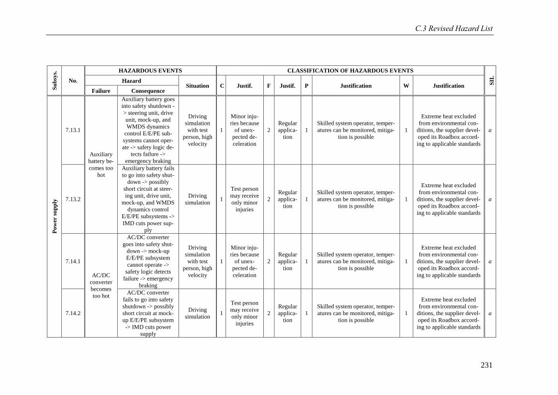
C.3 Revised Hazard List
231
Su
bsy
s.
No.
HAZARDOUS EVENTS CLASSIFICATION OF HAZARDOUS EVENTS
SIL
Hazard Situation C Justif. F Justif. P Justification W Justification
Failure Consequence
Po
wer
su
pp
ly
7.13.1
Auxiliary
battery be-
comes too
hot
Auxiliary battery goes
into safety shutdown -
> steering unit, drive
unit, mock-up, and
WMDS dynamics
control E/E/PE sub-
systems cannot oper-
ate -> safety logic de-
tects failure ->
emergency braking
Driving
simulation
with test
person, high
velocity
1
Minor inju-
ries because
of unex-
pected de-
celeration
2
Regular
applica-
tion
1
Skilled system operator, temper-
atures can be monitored, mitiga-
tion is possible
1
Extreme heat excluded
from environmental con-
ditions, the supplier devel-
oped its Roadbox accord-
ing to applicable standards
a
7.13.2
Auxiliary battery fails
to go into safety shut-
down -> possibly
short circuit at steer-
ing unit, drive unit,
mock-up, and WMDS
dynamics control
E/E/PE subsystems ->
IMD cuts power sup-
ply
Driving
simulation 1
Test person
may receive
only minor
injuries
2
Regular
applica-
tion
1
Skilled system operator, temper-
atures can be monitored, mitiga-
tion is possible
1
Extreme heat excluded
from environmental con-
ditions, the supplier devel-
oped its Roadbox accord-
ing to applicable standards
a
7.14.1
AC/DC
converter
becomes
too hot
AC/DC converter
goes into safety shut-
down -> mock-up
E/E/PE subsystem
cannot operate ->
safety logic detects
failure -> emergency
braking
Driving
simulation
with test
person, high
velocity
1
Minor inju-
ries because
of unex-
pected de-
celeration
2
Regular
applica-
tion
1
Skilled system operator, temper-
atures can be monitored, mitiga-
tion is possible
1
Extreme heat excluded
from environmental con-
ditions, the supplier devel-
oped its Roadbox accord-
ing to applicable standards
a
7.14.2
AC/DC converter
fails to go into safety
shutdown -> possibly
short circuit at mock-
up E/E/PE subsystem
-> IMD cuts power
supply
Driving
simulation 1
Test person
may receive
only minor
injuries
2
Regular
applica-
tion
1
Skilled system operator, temper-
atures can be monitored, mitiga-
tion is possible
1
Extreme heat excluded
from environmental con-
ditions, the supplier devel-
oped its Roadbox accord-
ing to applicable standards
a
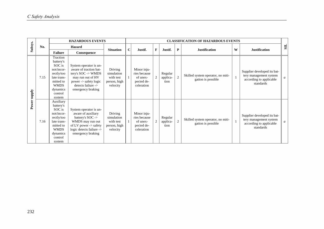
C Safety Analysis
232
Su
bsy
s.
No.
HAZARDOUS EVENTS CLASSIFICATION OF HAZARDOUS EVENTS
SIL
Hazard Situation C Justif. F Justif. P Justification W Justification
Failure Consequence
Po
wer
su
pp
ly
7.15
Traction
battery's
SOC is
not/incor-
rectly/too
late trans-
mitted to
WMDS
dynamics
control
system
System operator is un-
aware of traction bat-
tery's SOC -> WMDS
may run out of HV
power -> safety logic
detects failure ->
emergency braking
Driving
simulation
with test
person, high
velocity
1
Minor inju-
ries because
of unex-
pected de-
celeration
2
Regular
applica-
tion
2 Skilled system operator, no miti-
gation is possible 1
Supplier developed its bat-
tery management system
according to applicable
standards
a
7.16
Auxiliary
battery's
SOC is
not/incor-
rectly/too
late trans-
mitted to
WMDS
dynamics
control
system
System operator is un-
aware of auxiliary
battery's SOC ->
WMDS may run out
of LV power -> safety
logic detects failure ->
emergency braking
Driving
simulation
with test
person, high
velocity
1
Minor inju-
ries because
of unex-
pected de-
celeration
2
Regular
applica-
tion
2 Skilled system operator, no miti-
gation is possible 1
Supplier developed its bat-
tery management system
according to applicable
standards
a

233
C.4 Preliminary Hazard List for an Exem-
plary Application of the Safety Architecture
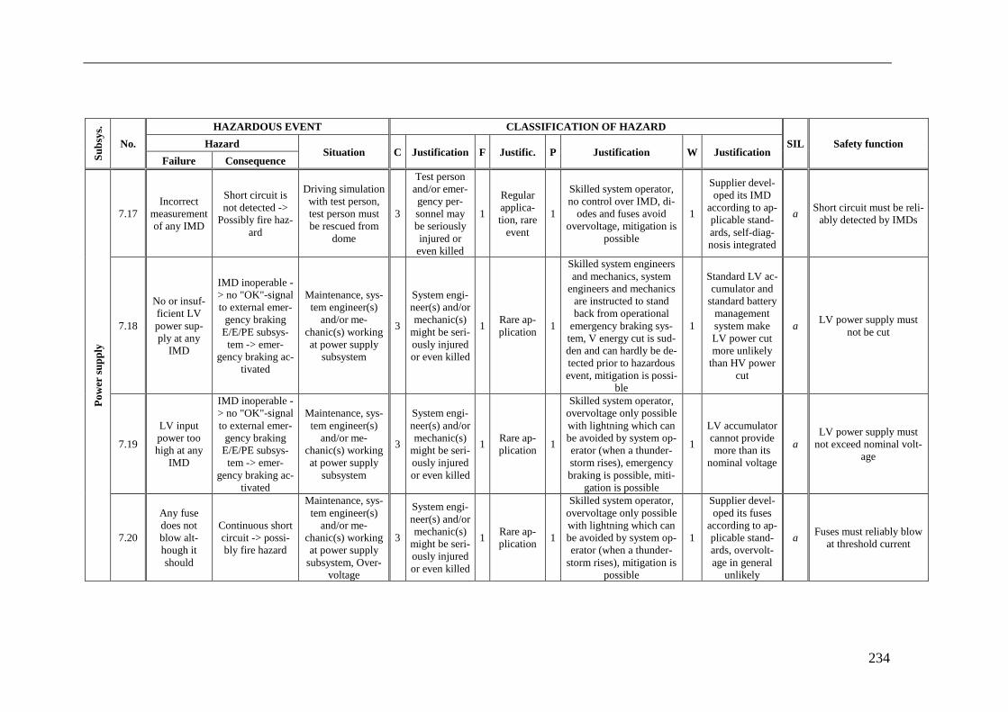
234
Su
bsy
s.
No.
HAZARDOUS EVENT CLASSIFICATION OF HAZARD
SIL Safety function Hazard Situation C Justification F Justific. P Justification W Justification
Failure Consequence
Po
wer
su
pp
ly
7.17
Incorrect
measurement
of any IMD
Short circuit is
not detected ->
Possibly fire haz-
ard
Driving simulation
with test person,
test person must
be rescued from
dome
3
Test person
and/or emer-
gency per-
sonnel may
be seriously
injured or
even killed
1
Regular
applica-
tion, rare
event
1
Skilled system operator,
no control over IMD, di-
odes and fuses avoid
overvoltage, mitigation is
possible
1
Supplier devel-
oped its IMD
according to ap-
plicable stand-
ards, self-diag-
nosis integrated
a Short circuit must be reli-
ably detected by IMDs
7.18
No or insuf-
ficient LV
power sup-
ply at any
IMD
IMD inoperable -
> no "OK"-signal
to external emer-
gency braking
E/E/PE subsys-
tem -> emer-
gency braking ac-
tivated
Maintenance, sys-
tem engineer(s)
and/or me-
chanic(s) working
at power supply
subsystem
3
System engi-
neer(s) and/or
mechanic(s)
might be seri-
ously injured
or even killed
1 Rare ap-
plication 1
Skilled system engineers
and mechanics, system
engineers and mechanics
are instructed to stand
back from operational
emergency braking sys-
tem, V energy cut is sud-
den and can hardly be de-
tected prior to hazardous
event, mitigation is possi-
ble
1
Standard LV ac-
cumulator and
standard battery
management
system make
LV power cut
more unlikely
than HV power
cut
a LV power supply must
not be cut
7.19
LV input
power too
high at any
IMD
IMD inoperable -
> no "OK"-signal
to external emer-
gency braking
E/E/PE subsys-
tem -> emer-
gency braking ac-
tivated
Maintenance, sys-
tem engineer(s)
and/or me-
chanic(s) working
at power supply
subsystem
3
System engi-
neer(s) and/or
mechanic(s)
might be seri-
ously injured
or even killed
1 Rare ap-
plication 1
Skilled system operator,
overvoltage only possible
with lightning which can
be avoided by system op-
erator (when a thunder-
storm rises), emergency
braking is possible, miti-
gation is possible
1
LV accumulator
cannot provide
more than its
nominal voltage
a
LV power supply must
not exceed nominal volt-
age
7.20
Any fuse
does not
blow alt-
hough it
should
Continuous short
circuit -> possi-
bly fire hazard
Maintenance, sys-
tem engineer(s)
and/or me-
chanic(s) working
at power supply
subsystem, Over-
voltage
3
System engi-
neer(s) and/or
mechanic(s)
might be seri-
ously injured
or even killed
1 Rare ap-
plication 1
Skilled system operator,
overvoltage only possible
with lightning which can
be avoided by system op-
erator (when a thunder-
storm rises), mitigation is
possible
1
Supplier devel-
oped its fuses
according to ap-
plicable stand-
ards, overvolt-
age in general
unlikely
a Fuses must reliably blow
at threshold current
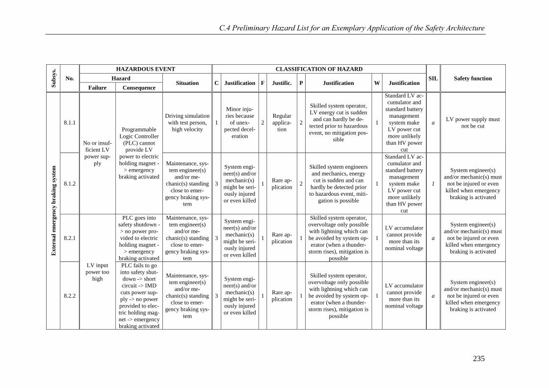
C.4 Preliminary Hazard List for an Exemplary Application of the Safety Architecture
235
Su
bsy
s.
No.
HAZARDOUS EVENT CLASSIFICATION OF HAZARD
SIL Safety function Hazard Situation C Justification F Justific. P Justification W Justification
Failure Consequence
Ex
tern
al
emer
gen
cy b
rak
ing s
yst
em
8.1.1
No or insuf-
ficient LV
power sup-
ply
Programmable
Logic Controller
(PLC) cannot
provide LV
power to electric
holding magnet -
> emergency
braking activated
Driving simulation
with test person,
high velocity
1
Minor inju-
ries because
of unex-
pected decel-
eration
2
Regular
applica-
tion
2
Skilled system operator,
LV energy cut is sudden
and can hardly be de-
tected prior to hazardous
event, no mitigation pos-
sible
1
Standard LV ac-
cumulator and
standard battery
management
system make
LV power cut
more unlikely
than HV power
cut
a LV power supply must
not be cut
8.1.2
Maintenance, sys-
tem engineer(s)
and/or me-
chanic(s) standing
close to emer-
gency braking sys-
tem
3
System engi-
neer(s) and/or
mechanic(s)
might be seri-
ously injured
or even killed
1 Rare ap-
plication 2
Skilled system engineers
and mechanics, energy
cut is sudden and can
hardly be detected prior
to hazardous event, miti-
gation is possible
1
Standard LV ac-
cumulator and
standard battery
management
system make
LV power cut
more unlikely
than HV power
cut
1
System engineer(s)
and/or mechanic(s) must
not be injured or even
killed when emergency
braking is activated
8.2.1
LV input
power too
high
PLC goes into
safety shutdown -
> no power pro-
vided to electric
holding magnet -
> emergency
braking activated
Maintenance, sys-
tem engineer(s)
and/or me-
chanic(s) standing
close to emer-
gency braking sys-
tem
3
System engi-
neer(s) and/or
mechanic(s)
might be seri-
ously injured
or even killed
1 Rare ap-
plication 1
Skilled system operator,
overvoltage only possible
with lightning which can
be avoided by system op-
erator (when a thunder-
storm rises), mitigation is
possible
1
LV accumulator
cannot provide
more than its
nominal voltage
a
System engineer(s)
and/or mechanic(s) must
not be injured or even
killed when emergency
braking is activated
8.2.2
PLC fails to go
into safety shut-
down -> short
circuit -> IMD
cuts power sup-
ply -> no power
provided to elec-
tric holding mag-
net -> emergency
braking activated
Maintenance, sys-
tem engineer(s)
and/or me-
chanic(s) standing
close to emer-
gency braking sys-
tem
3
System engi-
neer(s) and/or
mechanic(s)
might be seri-
ously injured
or even killed
1 Rare ap-
plication 1
Skilled system operator,
overvoltage only possible
with lightning which can
be avoided by system op-
erator (when a thunder-
storm rises), mitigation is
possible
1
LV accumulator
cannot provide
more than its
nominal voltage
a
System engineer(s)
and/or mechanic(s) must
not be injured or even
killed when emergency
braking is activated
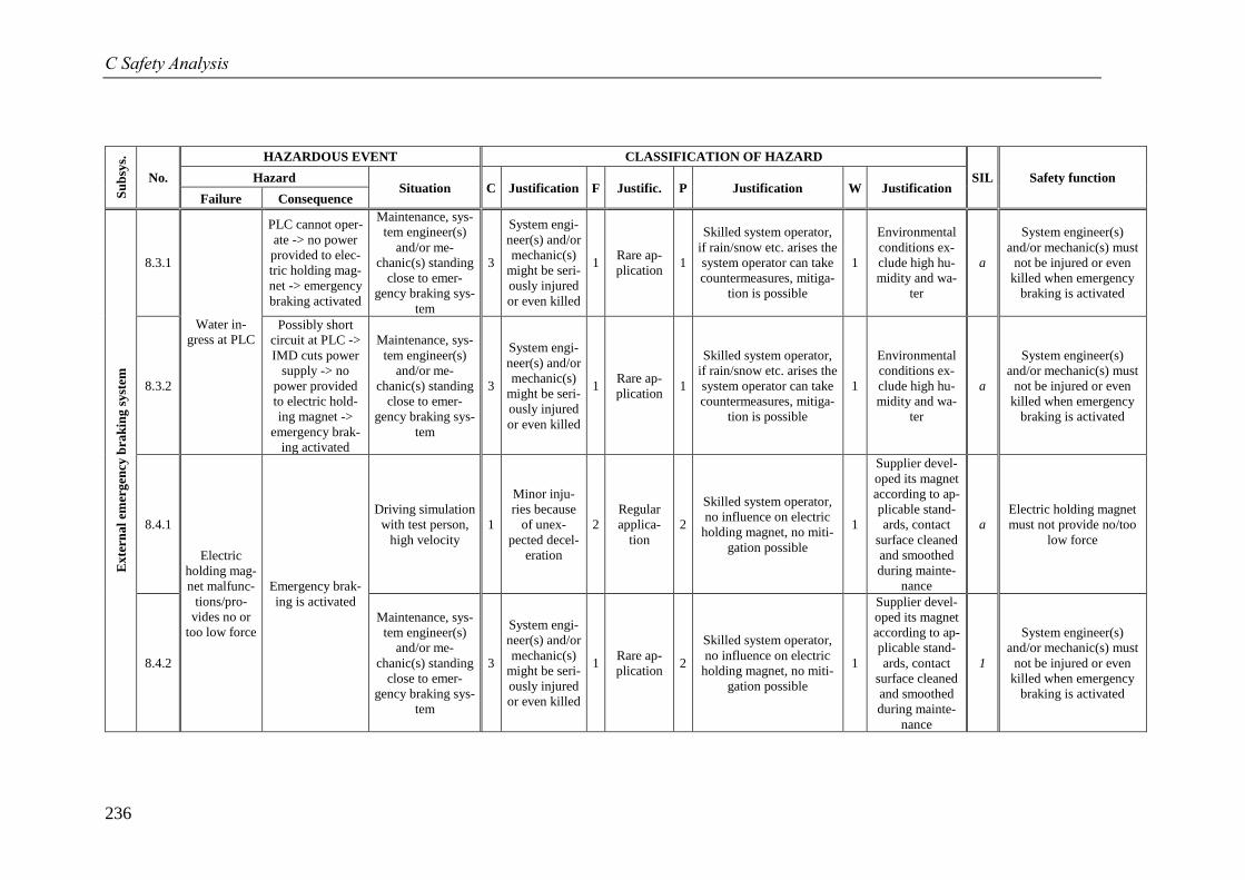
C Safety Analysis
236
Su
bsy
s.
No.
HAZARDOUS EVENT CLASSIFICATION OF HAZARD
SIL Safety function Hazard Situation C Justification F Justific. P Justification W Justification
Failure Consequence
Ex
tern
al
emer
gen
cy b
rak
ing s
yst
em
8.3.1
Water in-
gress at PLC
PLC cannot oper-
ate -> no power
provided to elec-
tric holding mag-
net -> emergency
braking activated
Maintenance, sys-
tem engineer(s)
and/or me-
chanic(s) standing
close to emer-
gency braking sys-
tem
3
System engi-
neer(s) and/or
mechanic(s)
might be seri-
ously injured
or even killed
1 Rare ap-
plication 1
Skilled system operator,
if rain/snow etc. arises the
system operator can take
countermeasures, mitiga-
tion is possible
1
Environmental
conditions ex-
clude high hu-
midity and wa-
ter
a
System engineer(s)
and/or mechanic(s) must
not be injured or even
killed when emergency
braking is activated
8.3.2
Possibly short
circuit at PLC ->
IMD cuts power
supply -> no
power provided
to electric hold-
ing magnet ->
emergency brak-
ing activated
Maintenance, sys-
tem engineer(s)
and/or me-
chanic(s) standing
close to emer-
gency braking sys-
tem
3
System engi-
neer(s) and/or
mechanic(s)
might be seri-
ously injured
or even killed
1 Rare ap-
plication 1
Skilled system operator,
if rain/snow etc. arises the
system operator can take
countermeasures, mitiga-
tion is possible
1
Environmental
conditions ex-
clude high hu-
midity and wa-
ter
a
System engineer(s)
and/or mechanic(s) must
not be injured or even
killed when emergency
braking is activated
8.4.1
Electric
holding mag-
net malfunc-
tions/pro-
vides no or
too low force
Emergency brak-
ing is activated
Driving simulation
with test person,
high velocity
1
Minor inju-
ries because
of unex-
pected decel-
eration
2
Regular
applica-
tion
2
Skilled system operator,
no influence on electric
holding magnet, no miti-
gation possible
1
Supplier devel-
oped its magnet
according to ap-
plicable stand-
ards, contact
surface cleaned
and smoothed
during mainte-
nance
a
Electric holding magnet
must not provide no/too
low force
8.4.2
Maintenance, sys-
tem engineer(s)
and/or me-
chanic(s) standing
close to emer-
gency braking sys-
tem
3
System engi-
neer(s) and/or
mechanic(s)
might be seri-
ously injured
or even killed
1 Rare ap-
plication 2
Skilled system operator,
no influence on electric
holding magnet, no miti-
gation possible
1
Supplier devel-
oped its magnet
according to ap-
plicable stand-
ards, contact
surface cleaned
and smoothed
during mainte-
nance
1
System engineer(s)
and/or mechanic(s) must
not be injured or even
killed when emergency
braking is activated
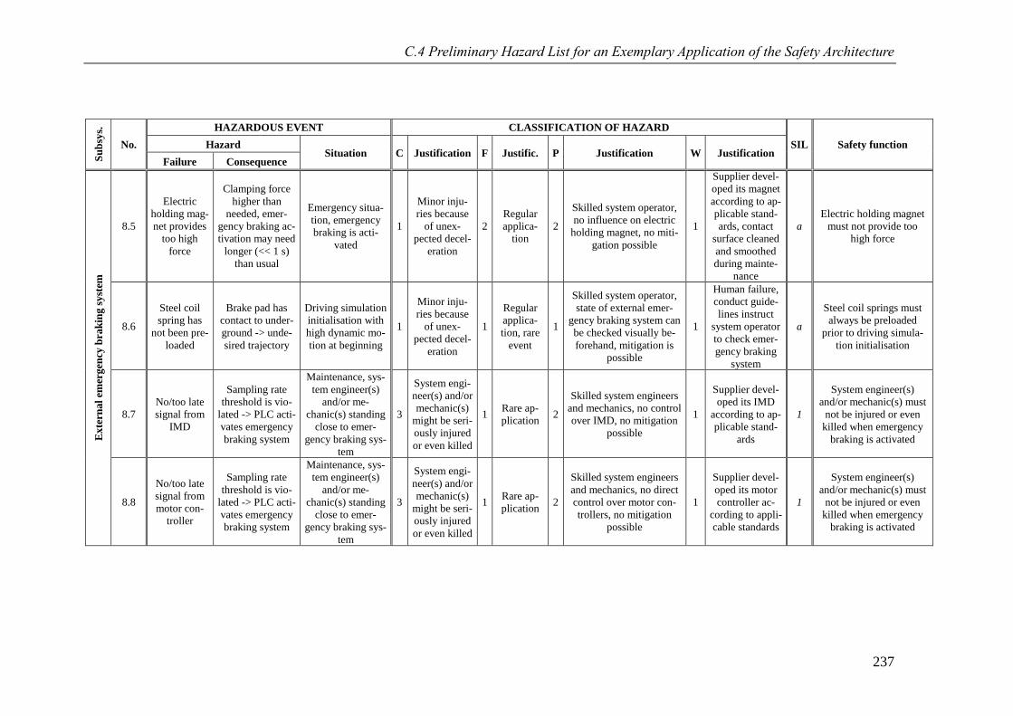
C.4 Preliminary Hazard List for an Exemplary Application of the Safety Architecture
237
Su
bsy
s.
No.
HAZARDOUS EVENT CLASSIFICATION OF HAZARD
SIL Safety function Hazard Situation C Justification F Justific. P Justification W Justification
Failure Consequence
Ex
tern
al
emer
gen
cy b
rak
ing s
yst
em
8.5
Electric
holding mag-
net provides
too high
force
Clamping force
higher than
needed, emer-
gency braking ac-
tivation may need
longer (<< 1 s)
than usual
Emergency situa-
tion, emergency
braking is acti-
vated
1
Minor inju-
ries because
of unex-
pected decel-
eration
2
Regular
applica-
tion
2
Skilled system operator,
no influence on electric
holding magnet, no miti-
gation possible
1
Supplier devel-
oped its magnet
according to ap-
plicable stand-
ards, contact
surface cleaned
and smoothed
during mainte-
nance
a
Electric holding magnet
must not provide too
high force
8.6
Steel coil
spring has
not been pre-
loaded
Brake pad has
contact to under-
ground -> unde-
sired trajectory
Driving simulation
initialisation with
high dynamic mo-
tion at beginning
1
Minor inju-
ries because
of unex-
pected decel-
eration
1
Regular
applica-
tion, rare
event
1
Skilled system operator,
state of external emer-
gency braking system can
be checked visually be-
forehand, mitigation is
possible
1
Human failure,
conduct guide-
lines instruct
system operator
to check emer-
gency braking
system
a
Steel coil springs must
always be preloaded
prior to driving simula-
tion initialisation
8.7
No/too late
signal from
IMD
Sampling rate
threshold is vio-
lated -> PLC acti-
vates emergency
braking system
Maintenance, sys-
tem engineer(s)
and/or me-
chanic(s) standing
close to emer-
gency braking sys-
tem
3
System engi-
neer(s) and/or
mechanic(s)
might be seri-
ously injured
or even killed
1 Rare ap-
plication 2
Skilled system engineers
and mechanics, no control
over IMD, no mitigation
possible
1
Supplier devel-
oped its IMD
according to ap-
plicable stand-
ards
1
System engineer(s)
and/or mechanic(s) must
not be injured or even
killed when emergency
braking is activated
8.8
No/too late
signal from
motor con-
troller
Sampling rate
threshold is vio-
lated -> PLC acti-
vates emergency
braking system
Maintenance, sys-
tem engineer(s)
and/or me-
chanic(s) standing
close to emer-
gency braking sys-
tem
3
System engi-
neer(s) and/or
mechanic(s)
might be seri-
ously injured
or even killed
1 Rare ap-
plication 2
Skilled system engineers
and mechanics, no direct
control over motor con-
trollers, no mitigation
possible
1
Supplier devel-
oped its motor
controller ac-
cording to appli-
cable standards
1
System engineer(s)
and/or mechanic(s) must
not be injured or even
killed when emergency
braking is activated
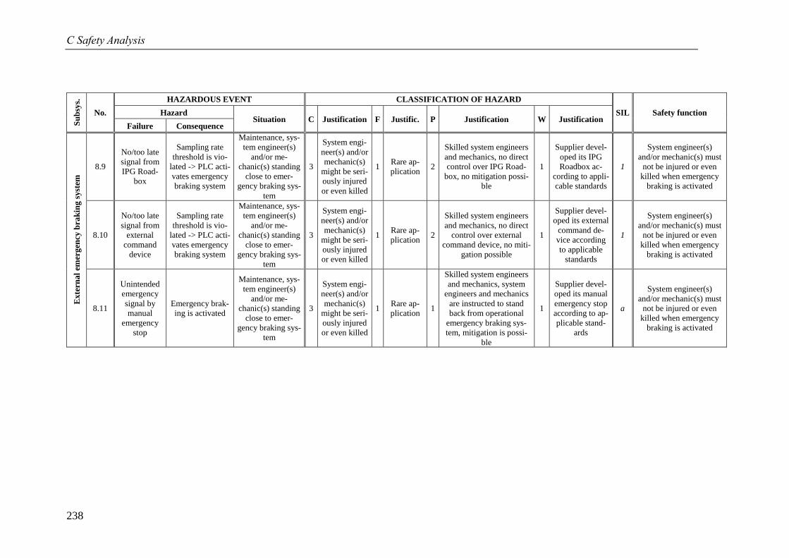
C Safety Analysis
238
Su
bsy
s.
No.
HAZARDOUS EVENT CLASSIFICATION OF HAZARD
SIL Safety function Hazard Situation C Justification F Justific. P Justification W Justification
Failure Consequence
Ex
tern
al
emer
gen
cy b
rak
ing s
yst
em
8.9
No/too late
signal from
IPG Road-
box
Sampling rate
threshold is vio-
lated -> PLC acti-
vates emergency
braking system
Maintenance, sys-
tem engineer(s)
and/or me-
chanic(s) standing
close to emer-
gency braking sys-
tem
3
System engi-
neer(s) and/or
mechanic(s)
might be seri-
ously injured
or even killed
1 Rare ap-
plication 2
Skilled system engineers
and mechanics, no direct
control over IPG Road-
box, no mitigation possi-
ble
1
Supplier devel-
oped its IPG
Roadbox ac-
cording to appli-
cable standards
1
System engineer(s)
and/or mechanic(s) must
not be injured or even
killed when emergency
braking is activated
8.10
No/too late
signal from
external
command
device
Sampling rate
threshold is vio-
lated -> PLC acti-
vates emergency
braking system
Maintenance, sys-
tem engineer(s)
and/or me-
chanic(s) standing
close to emer-
gency braking sys-
tem
3
System engi-
neer(s) and/or
mechanic(s)
might be seri-
ously injured
or even killed
1 Rare ap-
plication 2
Skilled system engineers
and mechanics, no direct
control over external
command device, no miti-
gation possible
1
Supplier devel-
oped its external
command de-
vice according
to applicable
standards
1
System engineer(s)
and/or mechanic(s) must
not be injured or even
killed when emergency
braking is activated
8.11
Unintended
emergency
signal by
manual
emergency
stop
Emergency brak-
ing is activated
Maintenance, sys-
tem engineer(s)
and/or me-
chanic(s) standing
close to emer-
gency braking sys-
tem
3
System engi-
neer(s) and/or
mechanic(s)
might be seri-
ously injured
or even killed
1 Rare ap-
plication 1
Skilled system engineers
and mechanics, system
engineers and mechanics
are instructed to stand
back from operational
emergency braking sys-
tem, mitigation is possi-
ble
1
Supplier devel-
oped its manual
emergency stop
according to ap-
plicable stand-
ards
a
System engineer(s)
and/or mechanic(s) must
not be injured or even
killed when emergency
braking is activated
239
Bibliography
Albrecht, T. et al.: Advanced Design Project, Fahrwiderstands- und Energiebedarfsbetrachtung
des MORPHEUS (2016)
Albrecht, Torben; Davoodi, Aschkan; Wilczynski, David; Betancourt Bautista, Miguel A.; Huber,
Katharina: Fahrwiderstands- und Energiebedarfsbetrachtung des MORPHEUS unter Berücksichtigung
der speziellen Eigenschaften der Bandagenreifen, Advanced Design Project
Technische Universität Darmstadt, Darmstadt, Germany, 2016
Ammon, D.; Schiehlen, W.: Advanced Road Vehicles: Control Technologies (2009)
Ammon, Dieter; Schiehlen, Werner: Advanced Road Vehicles: Control Technologies, Driver Assis-
tance, in: Schiehlen, Werner et al. (Eds.): Dynamical Analysis of Vehicle Systems, CISM International
Centre for Mechanical Sciences Nr. 497, Springer, Vienna, Austria, 2009
Baumann, G. et al.: How to Build Europe’s Largest Eight-Axes DS (2012)
Baumann, Gerd; Riemer, Thomas; Liedecke, Christoph; Rumbolz, Philip; Schmidt, Andreas: How to
Build Europe’s Largest Eight-Axes Motion Simulator, in: Espié, Stéphane; Kemeny, Andras; Mé-
rienne, Frédéric (Eds.): Proceedings of the Driving Simulation Conference Europe 2012 (DSC), Actes
INRETS A 134, INRETS, Bron, France, 2012
Baumann, G. et al.: The New DS of Stuttgart University (2012)
Baumann, Gerd; Riemer, Thomas; Liedecke, Christoph; Rumbolz, Philip; Schmidt, Andreas; Piegsa,
Anne: The New Driving Simulator of Stuttgart University, in: ATZlive (Ed.): Proceedings of the 12th
Stuttgart International Symposium Automotive and Engine Technology, Wiesbaden, Germany, 2012
Beidl, C.: Lecture Notes Combustion Engines II (2017)
Beidl, Christian: Lecture Notes Combustion Engines II, Darmstadt, Germany, 2017
Bel Power Solutions: 700DNC40-12-xG DC/DC Converter Data Sheet (2017)
Bel Power Solutions: 700DNC40-12-xG DC/DC Converter Data Sheet;
https://www.mouser.com/ds/2/643/bcd.00293_ae_700dnc40-12-xg-1116173.pdf, 2017, Access
07.03.2018
Berg, G.; Färber, B.: Vehicle in the Loop (2015)
Berg, Guy; Färber, Berthold: Vehicle in the Loop, in: Winner, Hermann (Ed.): Handbuch Fahrerassist-
enzsysteme, ATZ, Vieweg+Teubner, Wiesbaden, Germany, 2015
Betz, A. et al.: Concept Analysis of a WMDS (2012)
Betz, Alexander; Hämisch, Robert; Müller, Marius; Winner, Hermann: Concept Analysis of a
Wheeled Mobile Driving Simulator Showing an Omnidirectional Motion Base for Urban Traffic Sim-
ulation, in: Proceedings of the 16th Berechnung, Simulation und Erprobung im Fahrzeugbau
(SIMVEC), VDI-Berichte Nr. 2169, VDI, Düsseldorf, Germany, 2012
Betz, A. et al.: Motion Analysis of a WMDS (2012)
Betz, Alexander; Winner, Hermann; Ancochea, Marc; Graupner, Maren: Motion Analysis of a
Wheeled Mobile Driving Simulator for Urban Traffic Situations, in: Espié, Stéphane; Kemeny, An-
dras; Mérienne, Frédéric (Eds.): Proceedings of the Driving Simulation Conference Europe 2012
(DSC), Actes INRETS A 134, INRETS, Bron, France, 2012
Bibliography
240
Betz, A. et al.: Driving Dynamics Control of a WMDS (2013)
Betz, Alexander; Butry, Andreas; Junietz, Philipp; Wagner, Paul; Winner, Hermann: Driving Dynam-
ics Control of a Wheeled Mobile Driving Simulator Utilizing an Omnidirectional Motion Base for Ur-
ban Traffic Simulation, in: Proceedings of the Future Active Safety Technology Toward Zero-Traffic-
Accident (fast-zero) 2013, 2013
Betz, A. et al.: Development and Validation of a Safety Architecture of a WMDS (2014)
Betz, Alexander; Wagner, Paul; Albrecht, Torben; Winner, Hermann: Development and Validation of
a Safety Architecture of a Wheeled Mobile Driving Simulator, in: Kemeny, Andras; Espié, Stéphane;
Mérienne, Frédéric (Eds.): Proceedings of the Driving Simulation Conference Europe 2014 (DSC),
2014
Betz, A. et al.: Konzeptanalyse und Erprobung eines WMDS (2014)
Betz, Alexander; Wagner, Paul; Scheibe, Thomas; Winner, Hermann: Konzeptanalyse und Erprobung
eines selbstfahrenden Fahrsimulators für die Simulation von Stadtverkehr, in: Proceedings of the 17th
Simulation und Erprobung in der Fahrzeugentwicklung (SIMVEC), VDI, Düsseldorf, Germany, 2014
Betz, A.: Diss., Feasibility Analysis and Design of WMDS (2015)
Betz, Alexander: Feasibility Analysis and Design of Wheeled Mobile Driving Simulators for Urban
Traffic Simulation, Dissertation Technische Universität Darmstadt, Fortschrittberichte VDI: Reihe 12,
Issues 786, VDI, Düsseldorf, Germany, 2015
Betz, A.; Winner, H.: Patent Knee Lever Safety System (2014)
Betz, Alexander; Winner, Hermann: Fahrzeug mit einer omnidirektionalen Antriebseinrichtung, Tech-
nische Universität Darmstadt, 64289, Darmstadt, DE, Patent DE102014108387A1, Patent application
number: 102014108387, 2014
Blana, E.: A Survey of DS Around the World (1996)
Blana, Evi: A Survey of Driving Research Simulators Around the World, Leeds, UK, 1996
Boer, E. R. et al.: The Role of DS in Developing and Evaluating AD (2015)
Boer, Erwin R.; Penna, Mauro D.; Utz, Hans; Pedersen, Liam; Siehuis, Maarten: The Role of Driving
Simulators in Developing and Evaluating Autonomous Vehicles, in: Bülthoff, Heinrich; Kemeny, An-
dras; Pretto, Paolo (Eds.): Proceedings of the Driving Simulation Conference & Exhibition Europe
2015 (DSC), Tübingen, Germany, 2015
Breuer, B.; Bill, K. H.: Bremsenhandbuch (2012)
Breuer, Bert; Bill, Karlheinz H.: Bremsenhandbuch, ATZ, Vieweg+Teubner, Wiesbaden, Germany,
2012
Bülthoff, H. et al.: DSC Europe 2015 (2015)
Bülthoff, Heinrich; Kemeny, Andras; Pretto, Paolo (Eds.) Proceedings of the Driving Simulation Con-
ference & Exhibition Europe 2015 (DSC), Tübingen, Germany, 2015
Chapron, T.; Colinot, J.-P.: The New PSA Advanced DS (2007)
Chapron, Thomas; Colinot, Jean-Pierre: The New PSA Peugeot-Citroën Advanced Driving Simulator
Overall Design and Motion Cue Algorithm, in: Proceedings of the Driving Simulator Conference
North America 2007 (DSC), 2007
Clark et al.: NADS Motion System (2001)
Clark; Allen; Sparks; Hugh; Carmein; Judy: Unique Features and Capabilities of the NADS Motion
System, in: Proceedings of the 17th International Technical Conference on the Enhanced Safety of Ve-
hicles (ESV), 2001
Bibliography
241
Csillag, A.: Atlas of the Sensory Organs (2005)
Csillag, András: Atlas of the Sensory Organs, Humana Press, Totowa, NJ, USA, 2005
Dagdelen, M. et al.: MPC based MCA (2004)
Dagdelen, Mehmet; Reymond, Gilles; Kemeny, Andras; Bordier, Marc; Maizi, Nadia: MPC Based
Motion Cueing Algorithm: Development and Application to the ULTIMATE Driving Simulator, in:
Gauriat, Pierre; Kemeny, Andras (Eds.): Proceedings of the Driving Simulation Conference Europe
2004 (DSC), INRETS, Arcueil, France, 2004
Deutsches Institut für Normung e. V.: ISO 8855 (2013)
Deutsches Institut für Normung e. V.: Straßenfahrzeuge - Fahrzeugdynamik und Fahrverhalten - Be-
griffe, Beuth, Berlin, Germany, 2013
Donges, E.: Fahrsimulator (2001)
Donges, Edmund: Fahrsimulator, Bayrische Motoren Werke AG, Patent DE000010106150A1, Patent
application number: 101 06 150.1, 2001
Ericson, C. A.: Hazard Analysis Techniques for System Safety (2005)
Ericson, Clifton A.: Hazard Analysis Techniques for System Safety, Wiley-Interscience, Hoboken, NJ,
USA, 2005
Espié, S. et al.: DSC Europe 2012 (2012)
Espié, Stéphane; Kemeny, Andras; Mérienne, Frédéric (Eds.) Proceedings of the Driving Simulation
Conference Europe 2012 (DSC), Actes INRETSA 134, INRETS, Bron, France, 2012
Fischer, M.: Diss., MCA für eine realitätsnahe Bewegungssimulation (2009)
Fischer, Martin: Motion-Cueing-Algorithmen für eine realitätsnahe Bewegungssimulation, Disserta-
tion Technische Universität Carolo-Wilhelmina zu Braunschweig, Berichte aus dem DLR-Institut für
Verkehrssystemtechnik, Issues 5, Deutsches Zentrum für Luft- und Raumfahrt e.V., Braunschweig,
Germany, 2009
Fisher, D. L.: Handbook of DS (2011)
Fisher, Donald L.: Handbook of Driving Simulation for Engineering, Medicine, and Psychology, CRC
Press, Boca Raton, 2011
Gietelink, O. et al.: VEHIL: A Test Facility for ADAS (2004)
Gietelink, Olaf; Ploeg, Jeroen; Schutter, Bart d.; Verhaegen, Michel: VEHIL: A Test Facility for Vali-
dation of Fault Management Systems for Advanced Driver Assistance Systems, in: Proceedings of the
1st IFAC Symposium on Advances in Automotive Control (AAC), 2004
Glatzki, F.: Bachelor's thesis, Trajektorienüberlagerung und Lenkleistungsbedarf eines WMDS
(2016)
Glatzki, Felix: Untersuchung des Einflusses einer Trajektorienüberlagerung auf den Lenkleistungsbe-
darf eines selbstfahrenden Fahrsimulators, Bachelor's thesis
Technische Universität Darmstadt, Darmstadt, Germany, 2016
Gong, Z.; Konigorski, U.: Dynamic Modeling and Controller Design of WMDS (2016)
Gong, Zhongyi; Konigorski, Ulrich: Dynamic Modeling and Controller Design of an Omniwheel Mo-
bile Platform by Differential Parameterization, in: Proceedings of the 15th European Control Confer-
ence (ECC), IEEE, Piscataway, NJ, USA, 2016
Gong, Z.; Konigorski, U.: Model-Based Control of a WMDS (2016)
Gong, Zhongyi; Konigorski, Ulrich: Model-Based Control of a Wheeled Mobile Driving Simulator, in:
Kemeny, Andras et al. (Eds.): Proceedings of the Driving Simulation & Virtual Reality Conference
& Exhibition Europe 2016 (DSC), 2016
Bibliography
242
Gong, Z.; Konigorski, U.: Comparison of Different MCA in a WMDS (2017)
Gong, Zhongyi; Konigorski, Ulrich: Comparison of Different Motion Cueing Algorithms in a
Wheeled Mobile Driving Simulator, in: Kemeny, Andras et al. (Eds.): Proceedings of the Driving Sim-
ulation & Virtual Reality Conference & Exhibition Europe 2017 (DSC), 2017
Gong, Z.; Konigorski, U.: Modeling and Control of a WMDS (2017)
Gong, Zhongyi; Konigorski, Ulrich: Modeling and Control of a Wheeled Mobile Vehicle Driving Sim-
ulator by Differential Parameterization, in: Proceedings of the American Control Conference 2017
(ACC), IEEE, Piscataway, NJ, USA, 2017
Gough, V. E.; Whitehall, S. G.: Universal Tyre Test Machine (1962)
Gough, Vernon E.; Whitehall, S. G.: Universal Tyre Test Machine, in: Proceedings of 9th FISITA In-
ternational Technical Congress, 1962
Graubohm, R. et al.: Systematic Design Considering Functional Safety Aspects (2017)
Graubohm, Robert; Stolte, Torben; Bagschik, Gerrit; Reschka, Andreas; Maurer, Markus: Systematic
Design of Automated Driving Functions Considering Functional Safety Aspects, in: Proceedings of
the 8th Tagung Fahrerassistenz, 2017
Graupner, M.: Bachelor's thesis, Entwicklung eines repräsentativen Stadtparcours (2011)
Graupner, Maren: Entwicklung eines repräsentativen Stadtparcours mittels makroskopischer Betrach-
tung lokaler Verkehrsbereiche, Bachelor's thesis
Technische Universität Darmstadt, Darmstadt, Germany, 2011
Greenberg, J. et al.: Lateral Motion Cues During Simulated Driving (2003)
Greenberg, Jeff; Artz, Bruce; Cathey, Larry: The Effect of Lateral Motion Cues During Simulated
Driving, in: Proceedings of the Driving Simulator Conference North America 2003 (DSC), 2003
Groen, E. et al.: Psychophysical Thresholds of Linear Acceleration (2000)
Groen, Eric; Clari, Mario; Hosman, Ruud: Psychophysical Thresholds Associated with the Simulation
of Linear Acceleration, in: Proceedings of the AIAA Modeling and Simulation Technologies Confer-
ence 2000, AIAA, Reston, VI, USA, 2000
Hajek, H.: Diss., Längsdynamik von elektrifizierten Straßenfahrzeugen (2017)
Hajek, Hermann: Längsdynamik und Antriebsakustik von elektrifizierten Straßenfahrzeugen – Be-
schreibung und Gestaltung des emotionalen Erlebens, Dissertation Technische Universität München,
2017
Hein, E. et al.: Advanced Design Project, Entwicklung des unskalierten WMDS (2017)
Hein, Eric; Lamrabet, Youssef; Niess, Sammy; Schmeiß, Mirco: Entwicklung des selbstfahrenden
Fahrsimulators MORPHEUS 2.0, Advanced Design Project
Technische Universität Darmstadt, Darmstadt, Germany, 2017
Hettinger, L. J.; Riccio, G. E.: Visually Induced Motion Sickness (1992)
Hettinger, Lawrence J.; Riccio, Gary E.: Visually Induced Motion Sickness in Virtual Environments,
in: Presence: Teleoperators and Virtual Environments (3), Issues1, pp. 306–310, 1992
Honda Deutschland: Honda R&D DS (2017)
Honda Deutschland: Honda R&D führt revolutionären Fahrsimulator ein, 2017
Hüsing, K.: Fahrsimulator (2001)
Hüsing, Kurt: Fahrsimulator, Bayerische Motoren Werke AG, Patent DE000010158101A1, Patent ap-
plication number: 101 58 101.7, 2001
Bibliography
243
IEC TC 44 - Safety of machinery - electrotechnical aspects: IEC 62061 (2005)
IEC TC 44 - Safety of machinery - electrotechnical aspects: , IEC 1: Safety of Machinery - Functional
Safety of Safety-Related Electrical, Electronic and Programmable Electronic Control Systems, IEC,
Geneva, Switzerland, 2005
IEC TC 56 - Dependability: IEC 60812 (2006)
IEC TC 56 - Dependability: , IEC 2: Analysis Techniques for System Reliability - Procedure for Fail-
ure Mode and Effects Analysis (FMEA), IEC, Geneva, Switzerland, 2006
IEC TC 56 - Dependability: IEC 61025 (2006)
IEC TC 56 - Dependability: , IEC 2: Fault Tree Analysis (FTA), IEC, Geneva, Switzerland, 2006
IEC TC 56 - Dependability: IEC 61882 (2016)
IEC TC 56 - Dependability: , IEC 2: Hazard and Operability Studies (HAZOP Studies) - Application
Guide, IEC, Geneva, Switzerland, 2016
IEC TC 65/SC 65A - System aspects: IEC 61508 (2011)
IEC TC 65/SC 65A - System aspects: , IEC 2: Functional Safety of Electrical/Electronic/Programma-
ble Electronic Safety-Related Systems, IEC, Geneva, Switzerland, 2011
ISO TC 22/SC 32 Electrical and electronic components and general system aspects: ISO 26262
(2011)
ISO TC 22/SC 32 Electrical and electronic components and general system aspects: , ISO Road Vehi-
cles ‐ Functional Safety, ISO, Geneva, Switzerland, 2011
ISO/TC 199 - Safety of machinery: EN ISO 13849 (2015)
ISO/TC 199 - Safety of machinery: , ISO 3: Safety of Machinery -- Safety-Related Parts of Control
Systems, ISO, Geneva, Switzerland, 2015
ISO/TC 262 - Risk management: IEC 31010 (2009)
ISO/TC 262 - Risk management: , IEC 1: Risk Management -- Risk Assessment Techniques, ISO, Ge-
neva, Switzerland, 2009
Johnson, D. M.: Review of Simulator Sickness Research (2005)
Johnson, David M.: Introduction to and Review of Simulator Sickness Research, U.S. Army Research
Institute for the Behavioral and Social Sciences Research Report, Arlington, VA, USA, 2005
Kawamura, H. et al.: Highly-Responsive Acceleration Control for Nissan LEAF (2011)
Kawamura, Hiromichi; Ito, Ken; Karikomi, Takaaki; Kume, Tomohiro: Highly-Responsive Accelera-
tion Control for the Nissan LEAF Electric Vehicle, in: Proceedings of the SAE World Congress & Ex-
hibition 2011, SAE Technical Paper Series, SAE, 2011
Kemeny, A. et al.: DSC Europe 2016 (2016)
Kemeny, Andras; Mérienne, Frédéric; Colombet, Florent; Espié, Stéphane (Eds.) Proceedings of the
Driving Simulation & Virtual Reality Conference & Exhibition Europe 2016 (DSC), 2016
Kemeny, A. et al.: DSC Europe 2017 (2017)
Kemeny, Andras; Colombet, Florent; Mérienne, Frédéric; Espié, Stéphane (Eds.) Proceedings of the
Driving Simulation & Virtual Reality Conference & Exhibition Europe 2017 (DSC), 2017
Kroemer, K. H. et al.: Engineering Physiology (2010)
Kroemer, Karl H. E.; Kroemer, Hiltrud J.; Kroemer-Elbert, Katrin E.: Engineering Physiology,
Springer, Berlin, Heidelberg, Germany, 2010
Bibliography
244
Maurer, M. et al.: Autonomes Fahren (2015)
Maurer, Markus; Gerdes, J. C.; Lenz, Barbara; Winner, Hermann: Autonomes Fahren, Springer Vie-
weg, Berlin, Heidelberg, Germany, 2015
Max Planck Institute for Biological Cybernetics: CableRobot with Passenger (2015)
Max Planck Institute for Biological Cybernetics: CableRobot with Passenger;
https://tuebingen.mpg.de/en/homepage/detail/cablerobot-with-passenger-1.html, 2015, Access
11.10.2016
Murano, T. et al.: Development of High-Performance DS (2009)
Murano, Takahiko; Yonekawa, Takashi; Aga, Masami; Nagiri, Sueharu: Development of High-Perfor-
mance Driving Simulator, in: SAE International Journal of Passenger Cars - Mechanical Systems (1),
Issues 2, pp. 661–669, 2009
Nahon, M.; Reid, L. D.: Simulator MCA - A Designer's Perspective (1990)
Nahon, Meyer; Reid, Lloyd D.: Simulator Motion-Drive Algorithms - A Designer's Perspective, in:
Journal of Guidance, Control, and Dynamics (2), Issues 13, pp. 356–362, 1990
Nieuwenhuizen, F. M.; Bülthoff, H. H.: The MPI CyberMotion Simulator (2013)
Nieuwenhuizen, Frank M.; Bülthoff, Heinrich H.: The MPI CyberMotion Simulator, in: Journal of
Computing Science and Engineering (2), Issues 7, pp. 122–131, 2013
Osczevski, R.; Bluestein, M.: Wind Chill Equivalent Temperature Chart (2005)
Osczevski, Randall; Bluestein, Maurice: The New Wind Chill Equivalent Temperature Chart, in: Bul-
letin of the American Meteorological Society (10), Issues 86, pp. 1453–1458, 2005
Pfaffenbichler, P. C. et al.: Electric Mobility in Austria (2009)
Pfaffenbichler, Paul C.; Emmerling, Bettina; Jellinek, Reinhard; Krutak, Robin: Pre-Feasibility-Studie
zu "Markteinführung Elektromobilität in Österreich", Vienna, Austria, 2009
Pfeffer, P.; Harrer, M.: Lenkungshandbuch (2011)
Pfeffer, Peter; Harrer, Manfred: Lenkungshandbuch, Vieweg+Teubner, Wiesbaden, Germany, 2011
Ploeg, J. et al.: High Performance Automatic Guided Vehicle (2002)
Ploeg, Jeroen; van der Knaap, Albert C. M.; Verburg, Dirk J.: ATS/AGV-Design, Implementation and
Evaluation of a High Performance AGV, in: Proceedings of the IEEE Intelligent Vehicle Symposium
2002 (IV), IEEE, Piscataway, NJ, USA, 2002
17th SIMVEC (2014) Proceedings of the 17th Simulation und Erprobung in der Fahrzeugentwicklung
(SIMVEC), VDI, Düsseldorf, Germany, 2014
SAE World Congress 2011 (2011) Proceedings of the SAE World Congress & Exhibition 2011, SAE
Technical Paper Series, SAE, 2011
Reason, J. T.; Brand, J. J.: Motion Sickness (1975)
Reason, James T.; Brand, Joseph J.: Motion Sickness, Acad. Press, London, UK, 1975
Reid, L. D.; Nahon, M.: Flight Simulation MCA (1985)
Reid, Lloyd D.; Nahon, Meyer: Flight Simulation Motion-Base Drive Algorithms, UTIAS Report,
MMMM, 1985
Bibliography
245
Richter, A.; Scholz, M.: The Surveyor’s Guide to Automotive Simulation (2016)
Richter, Andreas; Scholz, Michael: “The Surveyor’s Guide to Automotive Simulation”: Development
and Evaluation of Guidelines for Straight Forward Road Surveying for Driving Simulator Databases
and Test Development of Driver Assistance and Automation Systems, in: Kemeny, Andras et al.
(Eds.): Proceedings of the Driving Simulation & Virtual Reality Conference & Exhibition Europe
2016 (DSC), 2016
SAE: Terms Related to Automated Driving Systems (2014)
SAE: Taxonomy and Definitions for Terms Related to On-Road Motor Vehicle Automated Driving
Systems, SAE; https://doi.org/10.4271/J3016_201401, 2014
Sato, Y. et al.: High Response Motor Nissan LEAF (2011)
Sato, Yoshinori; Ishikawa, Shigeaki; Okubo, Takahito; Abe, Makoto; Tamai, Katsunori: Development
of High Response Motor and Inverter System for the Nissan LEAF Electric Vehicle, in: Proceedings
of the SAE World Congress & Exhibition 2011, SAE Technical Paper Series, SAE, 2011
Schöner, H.-P.: Erprobung und Absicherung im dynamischen DS (2014)
Schöner, Hans-Peter: Erprobung und Absicherung im dynamischen Fahrsimulator, in: Proceedings of
the 17th Simulation und Erprobung in der Fahrzeugentwicklung (SIMVEC), VDI, Düsseldorf, Ger-
many, 2014
Schöner, H.-P.; Morys, B.: Dynamische DS (2015)
Schöner, Hans-Peter; Morys, Bernhard: Dynamische Fahrsimulatoren, in: Winner, Hermann (Ed.):
Handbuch Fahrerassistenzsysteme, ATZ, Vieweg+Teubner, Wiesbaden, Germany, 2015
Slob, J. J.: State-of-the-Art DS (2008)
Slob, J. J.: State-of-the-Art Driving Simulators, a Literature Survey, Eindhoven, Netherlands, 2008
Slob, J. J. et al.: The Wall is the Limit (2009)
Slob, J. J.; Kuijpers, M. R. L.; Rosielle, P. C. J. N.; Steinbuch, M.: A New Approach to Linear Motion
Technology: The Wall is the Limit, in: Kemeny, Andras (Ed.): Proceedings of the Driving Simulation
Conference Europe 2009 (DSC), INRETS, Arcueil, France, 2009
St. Pierre, M. E.: Diss., The Effects of Latency on Simulator Sickness in a HMD (2012)
St. Pierre, Matthew E.: The Effects of 0.2 Hz Varying Latency with 20-100 ms Varying Amplitude on
Simulator Sickness in a Helmet Mounted Display, Dissertation Clemson University, All Disserta-
tionsPaper 1036, TigerPrints, 2012
St. Pierre, M. E. et al.: The Effects of Latency on Simulator Sickness in a HMD (2015)
St. Pierre, Matthew E.; Banerjee, Salil; Hoover, Adam W.; Muth, Eric R.: The Effects of 0.2 Hz Vary-
ing Latency with 20-100 ms Varying Amplitude on Simulator Sickness in a Helmet Mounted Display,
in: Displays, Issues 36, pp. 1–8, 2015
Stewart, D.: A Platform with Six DOF (1965)
Stewart, David: A Platform with Six Degrees of Freedom, in: ARCHIVE: Proceedings of the Institu-
tion of Mechanical Engineers 1847-1982 (vols 1-196) (1965), Issues 180, pp. 371–386, 1965
Teufel, H. et al.: MPI Motion Simulator (2007)
Teufel, Harald; Nusseck, Hans-Günther; Beykirch, Karl; Butler, John; Kerger, Michael; Bülthoff,
Heinrich: MPI Motion Simulator: Development and Analysis of a Novel Motion Simulator, in: Pro-
ceedings of the AIAA Modeling and Simulation Technologies Conference and Exhibit 2007, AIAA,
2007

Bibliography
246
Tischer, W.; Prokop, G.: Selbstfahrender, hochdynamischer Fahrsimulator (2014)
Tischer, Wolfgang; Prokop, Günther: Selbstfahrender, hochdynamischer Fahrsimulator, Amst-System-
technik Gmbh, Technische Universität Dresden, Patent WO2014198861 A1, Patent application num-
ber: PCT/EP2014/062304, 2014
TU Delft: Validation Methodology for Fault-Tolerant ADAS (2014)
TU Delft: Validation Methodology for Fault-Tolerant Advanced Driver Assistance Systems;
http://www.dcsc.tudelft.nl/Research/Old/project_og_bds_mv.html, 2014, Access 21.10.2016
Tüschen, T.: Diplomarbeit, MCA für einen WMDS (2013)
Tüschen, Thomas: Konzeptionierung und Aufbau eines Motion-Cueing Algorithmus für einen selbst-
fahrenden Fahrsimulator, Diplomarbeit
Technische Universität Dresden, Dresden, Germany, 2013
Tüschen, T. et al.: Suspensions Design of a WMDS (2016)
Tüschen, Thomas; Kocksch, Felix; Beitelschmidt, Denise; Prokop, Günther: “auto.mobile-driving sim-
ulator” – Suspensions Design of a Wheel-Based Driving Simulator, in: Pfeffer, Peter (Ed.): Proceed-
ings of the 7th International Munich Chassis Symposium (chassis.tech plus), Springer, Wiesbaden,
Germany, 2016
Tüschen, T.; Prokop, G.: Development of a Highly Dynamic DS (2013)
Tüschen, Thomas; Prokop, Günther: Development of a Highly Dynamic Driving Simulator, in: Pro-
ceedings of the 16th ITI-Symposium, 2013
Tüschen, T.; Prokop, G.: System Design of a Highly Dynamic DS (2014)
Tüschen, Thomas; Prokop, Günther: System Design of a Highly Dynamic Driving Simulator by
Means of a FMU Co-Simulation, in: Proceedings of the 17th ITI-Symposium, 2014
UNITEK Industrie Elektronik GmbH: Manual Bamocar-D3 (2017)
UNITEK Industrie Elektronik GmbH: Manual Bamocar-D3; https://www.unitek-industrie-el-
ektronik.de/menu-bamocar-eng/menu-bamocar-pg-d3-eng, 2017, Access 16.01.2018
University of Leeds: University of Leeds DS (2016)
University of Leeds: UoLDS: Facility; http://www.uolds.leeds.ac.uk/facility/, 2016, Access
11.10.2016
van der Meulen, S. H.: Validation of Moving Base Simulation Model (2004)
van der Meulen, S. H.: Validation, Improvement and Analysis of Moving Base Simulation Model,
DCT rapporten Vol. 2005.056, Eindhoven, Netherlands, 2004
van der Slot, A. et al.: Integrated Fuels and Vehicles Roadmap to 2030+ (2016)
van der Slot, Arnoud; Schlick, Thomas; Pfeiffer, Walter; Baum, Markus: Integrated Fuels and Vehi-
cles Roadmap to 2030+, Munich, Germany, 2016
VI-grade: VI-grade DiM (2017)
VI-grade: DRIVER-IN-MOTION - Driving Simulation Solution | VI-grade; https://www.driverinmo-
tion.com/, 2017, Access 06.12.2017
VTI: VTI's simulator facilities
VTI: VTI's Simulator Facilities; http://www.vti.se/en/research-areas/vehicle-technology/vtis-driving-
simulators/, Access 11.10.2016
Bibliography
247
Wagner, P.: Master's thesis, Aufbau und Inbetriebnahme eines WMDS (2013)
Wagner, Paul: Aufbau und Inbetriebnahme eines selbstfahrenden Fahrsimulatorprüfstands, Master's
thesis
Technische Universität Darmstadt, Darmstadt, Germany, 2013
Wagner, P. et al.: Conception and Design of Mobile Driving Simulators (2014)
Wagner, Paul; Betz, Alexander; Winner, Hermann: Conception and Design of Mobile Driving Simula-
tors, in: Proceedings of the ASME International Design Engineering Technical Conferences and Com-
puters and Information in Engineering Conference 2014 (IDETC/CIE), ASME, New York, NY, USA,
2014
Wagner, P. et al.: Potentials and Limitations of Hexapods in WMDS (2015)
Wagner, Paul; Davoodi, Aschkan; Scheibe, Thomas; Albrecht, Torben; Winner, Hermann: Potentials
and Limitations of Hexapods in Wheeled Mobile Driving Simulators, in: Bülthoff, Heinrich; Kemeny,
Andras; Pretto, Paolo (Eds.): Proceedings of the Driving Simulation Conference & Exhibition Europe
2015 (DSC), Tübingen, Germany, 2015
Wagner, P. et al.: Power, Energy, and Latency Test Drives with MORPHEUS (2017)
Wagner, Paul; Zöller, Chris; Albrecht, Torben; Winner, Hermann: Power, Energy, and Latency Test
Drives with the Wheeled Mobile Driving Simulator Prototype MORPHEUS, in: Kemeny, Andras et
al. (Eds.): Proceedings of the Driving Simulation & Virtual Reality Conference & Exhibition Europe
2017 (DSC), 2017
Wentink, M. et al.: Design and Evaluation of MCA for Desdemona Simulator (2005)
Wentink, Mark; Bles, Wim; Hosman, Ruud; Mayrhofer, Michael: Design and Evaluation of Spherical
Washout Algorithm for Desdemona Simulator, in: Proceedings of the AIAA Modeling and Simulation
Technologies Conference and Exhibit 2005, AIAA, 2005
Wildzunas, R. M. et al.: Visual Display Delay Effects on Pilot Performance (1996)
Wildzunas, Robert M.; Barron, Terry L.; Wiley, Roger W.: Visual Display Delay Effects on Pilot Per-
formance, in: Aviation, Space, and Environmental Medicine (3), Issues 67, pp. 214–221, 1996
Winner, H.: Handbuch Fahrerassistenzsysteme (2015)
Winner, Hermann (Ed.) Handbuch Fahrerassistenzsysteme, ATZ, Vieweg+Teubner, Wiesbaden, Ger-
many, 2015
Zeeb, E.: Daimler’s New Full-Scale, High-Dynamic DS (2010)
Zeeb, Eberhard: Daimler’s New Full-Scale, High-Dynamic Driving Simulator – A Technical Over-
view, in: Kemeny, Andras; Mérienne, Frédéric; Espié, Stéphane (Eds.): Proceedings of the Driving
Simulation Conference Europe 2010 (DSC), 2010
Zöller, C.: Master's thesis, Implementierung und Parametrierung eines Reifenmodells für WMDS
(2014)
Zöller, Chris: Implementierung eines Fahrdynamiksimulationstauglichen Modells des Bandagenrei-
fens des WMDS sowie Identifikation der relevanten Parameter, Master's thesis
Technische Universität Darmstadt, Darmstadt, Germany, 2014
Zöller, C. et al.: Tire Concept Investigation for WMDS (2016)
Zöller, Chris; Wagner, Paul; Winner, Hermann: Tire Concept Investigation for Wheeled Mobile Driv-
ing Simulators, in: Kemeny, Andras et al. (Eds.): Proceedings of the Driving Simulation & Virtual Re-
ality Conference & Exhibition Europe 2016 (DSC), 2016

Bibliography
248
Zöller, C. et al.: Tires and Vertical Dynamics of WMDS (2017)
Zöller, Chris; Wagner, Paul; Winner, Hermann: Tires and Vertical Dynamics of Wheeled Mobile
Driving Simulators, in: Transportation Research Part F: Traffic Psychology and Behaviour, 2017
249
Publications
Betz, A.; Butry, A.; Junietz, P.; Wagner, P.; Winner, H.: Driving Dynamics Control
of a Wheeled Mobile Driving Simulator Utilizing an Omnidirectional Motion Base for
Urban Traffic Simulation. In Proceedings of the Future Active Safety Technology toward
zero-traffic-accident – FAST-zero, September 22-26, Nagoya, Japan, 2013
Wagner, P.; Betz, A.; Winner, H.: Conception and Design of Mobile Driving Simula-
tors. In Proceedings of the ASME 2014 International Design Engineering Technical Con-
ferences & Computers and Information in Engineering Conference – IDETC/CIE, August
17-20, Buffalo, NY, USA, 2014.
Betz, A.; Wagner, P.; Albrecht, T.; Winner, H.: Development and Validation of a
Safety Architecture of a Wheeled Mobile Driving Simulator. In Proceedings of the Driv-
ing Simulation Conference Europe – DSC, September 4-5, Paris, France, 2014.
Betz, A.; Wagner, P.; Scheibe, T.; Winner, H.: Konzeptanalyse und Erprobung eines
selbstfahrenden Fahrsimulators für die Simulation von Stadtverkehr, In Proceedings of
the 16th Simulation und Erprobung in der Fahrzeugentwicklung – SIMVEC, November
18-19, Baden-Baden, Germany, 2014.
Wagner, P.; Davoodi, A.; Scheibe, T.; Albrecht, T.; Betz, A.; Winner, H.: Potentials
and Limitations of Hexapods in Wheeled Mobile Driving Simulators. In Proceedings of
the Driving Simulation Conference & Exhibition Europe -– DSC, September 16-18, Tü-
bingen, Germany, 2015.
Schneider, J.; Wagner, P.; Winner, H.: Situational Adaptive Chassis: Where are the
Limits?. In Proceedings of the 24th Aachener Kolloquium –- AC, October 5-7, Aachen,
Germany, 2015.
Wagner, P.; Winner, H.: MiniMax-Projekt – Fahrwerkskonzept für urbanen Straßen-
verkehr. Automobiltechnische Zeitschrift -– ATZ 118(6): 26–33, 2016.
Wagner, P.; Zöller, C..; Winner, H.: Safety Analysis for Wheeled Mobile Driving Sim-
ulators. In Proceedings of the Driving Simulation Conference & Virtual Reality Confer-
ence & Exhibition Europe -– DSC, September 7-9, Paris, France, 2016.
Zöller, C.; Wagner, P.; Winner, H.: Tire Concept Investigation for Wheeled Mobile
Driving Simulators. In Proceedings of the Driving Simulation Conference & Virtual Re-
ality Conference & Exhibition Europe -– DSC, September 7-9, Paris, France, 2016.
Publications
250
Kalbfleisch, J.; Wagner, P.; Winner, H.: MiniMax – a Situational and Geometrical
Adaptive Chassis: Driving Safety AND Space Efficiency. In Proceedings of the 13th In-
ternational Symposium on Advanced Vehicle Control -– AVEC, September 13-16, Mu-
nich, Germany, 2016.
Wagner, P.; Zöller, C.; Albrecht, T.; Winner, H.: Power, Energy, and Latency Test
Drives with the Wheeled Mobile Driving Simulator Prototype MORPHEUS. In Proceed-
ings of the Driving Simulation Conference & Virtual Reality Conference & Exhibition
Europe -– DSC, September 6-8, Stuttgart, Germany, 2017.
Zöller, C.; Wagner, P.; Winner, H.: Tire Concept Investigation for Wheeled Mobile
Driving Simulators. Transportation Research Part F: Traffic Psychology and Behaviour,
Special Issue Driving Simulation, 2017.
251
Supervised Students’ Thesis
Li, X., Wang, C., Lu, F., Yu, L., Li, Z.: Konzeption eines Prüfstands zur Bestimmung
der Abhängigkeit von Reifenschräglauf und Seitenkraft bei Bandagereifen, Advanced De-
sign Project Nr. 50/14, 2014.
Kettmann, N.: Menschliche Wahrnehmungsschwellen für Bewegung in der Fahrsimula-
tion, Forschungsseminar Nr. 105/14, 2014.
Drachenberg, A.: Implementierung eines Bandagereifenmodells des selbstfahrenden
Fahrsimulators in IPG CarMaker, Bachelorthesis Nr. 1178/14, 2014.
Prinz, J.: Putting into Operation of Wheeled Mobile Driving Simulator Including its
Safety System, International Research Experience, 2014.
Scheibe, T.: Untersuchung der mechanischen Kopplung im selbstfahrenden Fahrsimula-
tor sowie Identifikation von Reifenparametern, Masterthesis Nr. 546/14, 2014.
Albrecht, T.: Implementierung und Parametrisierung eines Hexapod in den Motion Cu-
eing Algorithmus eines selbstfahrenden Fahrsimulators, Bachelorthesis Nr. 1200/14,
2014.
Davoodi, A.: Stillstandsvermeidung der Räder im selbstfahrenden Fahrsimulator, Bache-
lorthesis Nr. 1204/14, 2014.
Schneider, J.: Untersuchung der fahrdynamischen Auswirkungen eines situativ anpass-
baren Fahrwerks auf die Fahrstabilität, Masterthesis Nr. 548/14, 2014.
Zöller, C.: Implementierung eines Fahrdynamiksimulationstauglichen Modells des Ban-
dagenreifens des WMDS sowie Identifikation der relevanten Parameter, Masterthesis Nr.
557/14, 2014.
Zhang, Z.: Modelling and Design of a Safety System for a Wheeled Mobile Driving
Simulator, International Research Experience, 2015.
Bilgic Istoc, S.: Einbindung und Validierung von Testmanövern in den selbstfahrenden
Fahrsimulator, Masterthesis Nr. 578/15, 2015.
Kalbfleisch, J.: Konzeptauswahl für ein situativ anpassbares Fahrwerk, Masterthesis Nr.
580/15, 2015.
Yang, J.: Überarbeitung und Optimierung des Motion Cueing Algorithmus eines selbst-
fahrenden Fahrsimulators, Masterthesis Nr. 581/15, 2015.
Butry, A.: Analyse und Weiterentwicklung der Ansteueralgorithmen eines Fahrsimula-
tors, Masterthesis Nr. 582/15, 2015.
Supervised Students’ Thesis
252
Schneider, J.; Seyfried, S.; Brötz, N.; Alles, J.; Mrosek, M.; Rösner, A.: Weiterent-
wicklung eines automatisierten und Smartphone-basierten Aufzeichnungssystem von
Fahrdaten, Advanced Design Project Nr. 66/15, 2015.
Forster, P.: Entwurf eines hochdynamischen und überaktuierten Fahrzeugs zum präzisen
Handling von Objekten, Diplomarbeit Nr. 595/15, 2015.
Xu, C.: Analyse von Umfeldsensorik für selbstfahrende Roboter, Forschungsseminar Nr.
146/15, 2015.
Senol, S.: Analyse von Sicherheitsmechanismen für selbstfahrende Roboter, Forschungs-
seminar Nr. 147/15, 2015.
Steier. J.: Erweiterung der Bewegungsregelung eines selbstfahrenden Fahrsimulators,
Masterthesis Nr. 598/15, 2015.
Lutwitzi, M.: Entwurf eines Konzepts für eine Umfelderkennung für selbstfahrende
Fahrsimulatoren, Bachelorthesis Nr. 1272/16, 2016.
Glatzki, F.: Untersuchung des Einflusses einer Trajektorienüberlagerung auf den
Lenkleistungsbedarf eines selbstfahrenden Fahrsimulators, Bachelorthesis Nr. 1273/16,
2016.
Bonakdar, F.: Verbesserung der Bewegungsregelung eines selbstfahrenden Fahrsimula-
tors, Bachelorthesis Nr. 1275/16, 2016.
Titze, J.: Recherche und Vergleich von Personal Electric Vehicles und geometrisch ver-
stellbaren Fahrwerken, Studienarbeit Nr. 1276/16, 2016.
Luft, A.: Konzeption eines skalierten Personal Electric Vehicle mit aktiver Spurweite-
und Schwerpunktverstellung, Masterthesis Nr. 618/16, 2016.
Betschinske, D.: Untersuchung von Methoden zur Verringerung des Lenkleistungsbe-
darfs des selbstfahrenden Fahrsimulators, Bachelorthesis Nr. 1287/16, 2016.
Perschbacher, R.: Untersuchung der Eignung eines Hexapods zur Maskierung von Stö-
reinflüssen aus der Lenkung an einem selbstfahrenden Fahrsimulator, Bachelorthesis Nr.
1288/17, 2017.
Hein, E.; Lamrabet, Y.; Niess, S.; Weiher, M.: Entwicklung des selbstfahrenden Fahr-
simulators MORPHEUS 2.0, Advanced Design Project Nr. 100/17, 2017.