ecse 6770- software engineering - 1 - ho 8 © hy 2012 lecture 8 system design architectural topology...
TRANSCRIPT

ECSE 6770- Software Engineering
- 1 -HO 8
© HY 2012
Lecture 8
System DesignArchitectural topology
A system can be laid-out in a particular configuration. If the designers of the system have utilized good design principles, such configuration would be appropriate not only to the problem environment but also to the design decisions made to deliver a solution to the problem. Therefore architectural topology (how a design is laid-out) is important.
In computerized system solutions, two categories of topology become important. These are:
Physical topology
Logical topology
ECSE 6770- Software Engineering
- 2 -HO 8
© HY 2012
Lecture 8
System DesignPhysical topology
Physical topology deals with how the physical elements of a system have been laid-out. This can often impact issues such as performance, reliability or even functionality. Software design decisions have to be made in such a way that is harmonious with the type of physical topology adopted and vice-versa.
ECSE 6770- Software Engineering
- 3 -HO 8
© HY 2012
Lecture 8
System DesignLogical topology
Logical topology deals with the logical inter-relationship of design elements as opposed to physical equipment layout. Logically a topology can be:
Centralized or Distributed
When distributed, it can be distributed based on
Data or Process or both
Communication and flow of information can be on a
Peer to peer or Client – server
basis.
ECSE 6770- Software Engineering
- 4 -HO 8
© HY 2012
Lecture 8
System DesignLogically, the structure of all software systems may be described in terms of three concepts or elements. These are:
The facility, module, or object that performs the required service,
The facility, module or object that requests a service to be performed,
An effective means for communication of the two above elements.
Centralized topology
Simply put, in a centralized topology these three elements are co-located or more accurately, are not explicitly separated logically or physically.
ECSE 6770- Software Engineering
- 5 -HO 8
© HY 2012
Lecture 8
System DesignDistribution:
Principles of good design such as modularity and abstraction often lead to, or suggest, a logical topology other than centralization. We can logically abstract into modules, specific services that can be supplied, and into other modules those that might request these. These collaborating modules would then communicate via an appropriate mechanism of communication usually (but not necessarily) based on a multi-node physical topology such as a bus, ring or internetwork. Such multi-node physical topology is colloquially called a network. When these communicating modules are placed non-centrally (usually on more than one physical node), we have distribution. Such a system is called a distributed system.

ECSE 6770- Software Engineering
- 6 -HO 8
© HY 2012
Lecture 8
System DesignData DistributionIt is possible to distribute a system based on location of the data elements. For example a detective might use a desk-top machine to check the criminal records of a person. If the databases containing these records are however not on that desk-top machine, and the system has to communicate over a network with other computers that hosts these types of databases (say at FBI, INTERPOL, Scotland yard, etc.), then we have a data-distributed system.
Another example might be a remote banking system in which the Automated Teller Machine (ATM) might have to consult several databases at various banks (physically and logically elsewhere) in order to check the cardholder’s account details, depending on where the account is held.
ECSE 6770- Software Engineering
- 7 -HO 8
© HY 2012
Lecture 8
System Design
Data distribution may go beyond this multiple database configuration and we may have a distributed database situation.
In a distributed database situation, a single logically coherent database may be physically placed on several machines in several distributed locations. Distributed databases are gaining in popularity and they might become the dominant data storage strategy in the future.

ECSE 6770- Software Engineering
- 8 -HO 8
© HY 2012
Lecture 8
System DesignProcess DistributionIt is also possible to distribute the processing performed in a system. For example in an on-line stockbrokerage system the share trading operations might be on one node (the customers’), whilst the system administration processes might be available only on a specific node and location at the HQ and not accessible to the clients.
Process distribution can also go beyond this level so that for example there would be process distribution even within a single unit of work. For example share trading can be deemed as a single activity or unit of work. However, for the on-line stockbrokerage system it is possible to have the presentation processes (GUI etc.) on one category of machine, and the share transacting processes on another.
ECSE 6770- Software Engineering
- 9 -HO 8
© HY 2012
Lecture 8
System DesignData and Process Distribution:
As the astute reader might have already surmised, pure data or pure process distribution is limiting and logically difficult to achieve. Distributed system usually are distributed based on both data and process. A popular form of such distribution is object distribution where individual objects or small collections might be on any machine yet provide the required functionality as if present locally.
Irrespectively of type of distribution, the inter-action between modules might take two distinct forms: Client-server and Peer-to-peer. We shall discuss these shortly.
ECSE 6770- Software Engineering
- 10 -HO 8
© HY 2012
Lecture 8
System DesignClient-server
The arrangement or protocol where the module requesting a service from another module does this via sending it a message is called the client-server arrangement (sometimes unofficially called an architecture). In such an arrangement the module sending the request is called the client and the module serving the request is called the server.
Client-server arrangements can be made at various levels of abstraction, for example one can conceive of an entire system that is a client to another system, a sub-system might be a client to another sub-system, a module might act as a client to another module.

ECSE 6770- Software Engineering
- 11 -HO 8
© HY 2012
Lecture 8
System DesignIn fact the object oriented paradigm can be viewed as the implementation of the client-server arrangement at the class (actually object) level.
In most client-server arrangements, the request message sent to the server is usually transported via a network. It is however possible to conceive of a client-server arrangement where all the modules are on the same node or machine. For example a centrally located object-oriented system is centralized yet it has a client-server arrangement.
Client Servermessage
ECSE 6770- Software Engineering
- 12 -HO 8
© HY 2012
Lecture 8
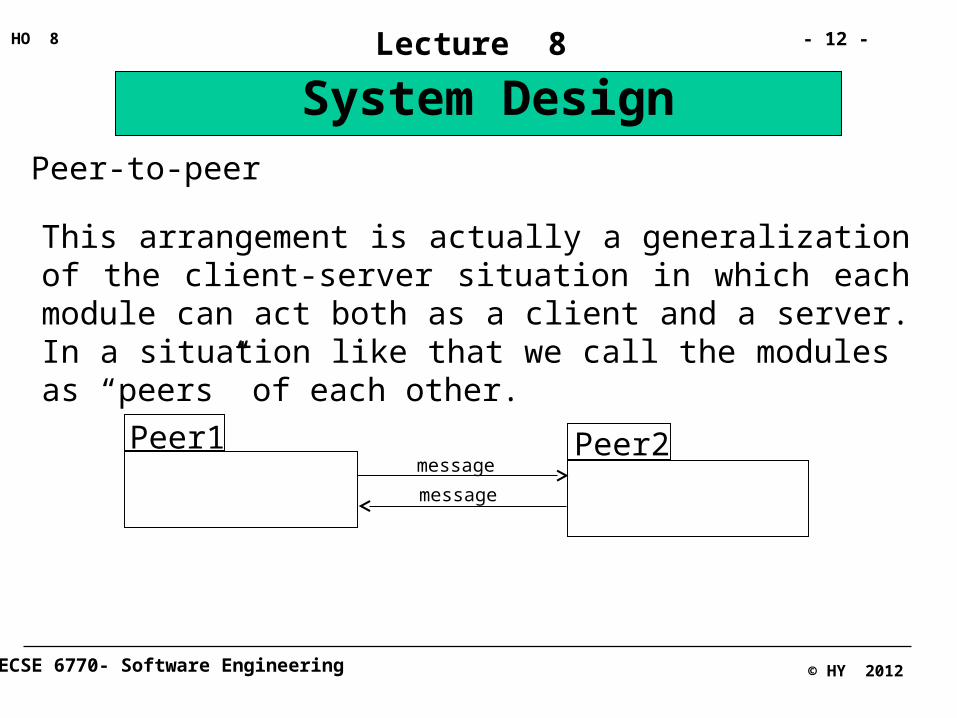
System DesignPeer-to-peer
This arrangement is actually a generalization of the client-server situation in which each module can act both as a client and a server. In a situation like that we call the modules as “peers” of each other.
Peer1 Peer2message
message

ECSE 6770- Software Engineering
- 13 -HO 8
© HY 2012
Lecture 8
System DesignBridge designers or architects do not design their bridges or buildings from scratch every time. There are a number of inter-related design concepts and ideas that work well under certain conditions or are appropriate in solving a particular type of problem. For example a particular arrangement of pylons and spans leads to a particular bridge design called “cantilever”. There are many cantilever bridges world-wide, all are different but they all have the same basic design style in terms of the arrangements of their basic design elements.
Similarly in software design, a particular scheme of relating sub-systems or modules with each other in order to deliver a solution is called an architectural style. We shall discuss some of the most important of these styles.

ECSE 6770- Software Engineering
- 14 -HO 8
© HY 2012
Lecture 8
System Design
Architectural design styles:
There are many styles of architectural design available. Some are specific to a particular application area or a particular type of design problem. Although usually called design styles, these are best referred to as a particular solution pattern or a framework, depending on the level abstraction, extent and detail provided. Some, however, are more general and can be truly called design styles. Of these we shall cover the following, postponing the discussion of the former category to later.
Layered Partitioned Encapsulated
Repository Pipes and Filters

ECSE 6770- Software Engineering
- 15 -HO 8
© HY 2012
Lecture 8
System Design
Layered Style:
Applying the design principles of modularity, abstraction and provision of multiple levels of granularity can lead to a particular arrangement called a layered style. In a purely layered style, the system is decomposed into several hierarchical modules, each called a layer. These layers are then arranged in such a way that each layer is only a server for the layer or layers above it and a client to the level or levels below it. As such a layer can request services from the layer or layers below and utilize these to provide more complex, higher level services in turn for a higher level client layer to it.

ECSE 6770- Software Engineering
- 16 -HO 8
© HY 2012
Lecture 8
System Design
A layered system may be of a “stack” style where each layer constitutes only one module or more generally of a “tree” style where a layer may have more than one sub-ordinate layer.
Layer 1
Layer 2
Layer 3
Layer 4

ECSE 6770- Software Engineering
- 17 -HO 8
© HY 2012
Lecture 8
System Design
Open layered architecture vs. Closed layered architecture
Layered style can be Open or Closed.
An Open layered style is the one in which each layer can depend on more than only the immediate layer below it.
A Closed layered style is the one in which each layer can only access the level immediately below it and no further.
Both styles are frequently used but the closed style is winning preference as it displays a greater number of good design principles.

ECSE 6770- Software Engineering
- 18 -HO 8
© HY 2012
Lecture 8
System Design
Application
CORBA
TCP/IP
Application Layer
Middleware
Socket Layer

ECSE 6770- Software Engineering
- 19 -HO 8
© HY 2012
Lecture 8
System DesignPartitioned Style:
We saw that the layered style utilized the client-server arrangement. Using a peer-to-peer arrangement instead can lead to another style called a partitioned style.
In a partition style the system is decomposed into a set of sub-systems. These sub-systems that are at peer level with one another, each become responsible for a different category or class of service. Operating System
File Management
Process Management
I/O

ECSE 6770- Software Engineering
- 20 -HO 8
© HY 2012
Lecture 8
System DesignEncapsulated Style:
The encapsulated style is in fact the implementation of the object-oriented paradigm as a design style. In an encapsulated style abstracted modules communicate via messages in a client-server arrangement. Modules can contain many classes and the organization of classes within these modules or indeed the organization of modules within sub-systems may in fact be based on a layered or partition style, but is usually a mix of both. This style lends itself well to distribution.

ECSE 6770- Software Engineering
- 21 -HO 8
© HY 2012
Lecture 8
System DesignRepository Style:
The repository style is one in which otherwise relatively independent modules or sub-systems communicate by accessing and modifying a central back-bone (usually a database or database system) called a repository. The repository style architecture is widely used for MIS systems or other similar systems that heavily rely on databases. It is an appropriate architecture for situations where largely independent sub-systems rely on a complex and large data structure. One advantage of the repository system is that control flow and particularly concurrent data access can be controlled relatively easily through the existence of the central repository. Control flow may be central or distributed.

ECSE 6770- Software Engineering
- 22 -HO 8
© HY 2012
Lecture 8
System Design
Central control flow:
This is when the repository is in control for example as in many database systems when a trigger on the data is received by the client module. When the state of a repository is used to trigger the peripheral sub-systems or modules, the style is called a blackboard system.
Distributed control flow:
This is when the peripheral modules control the flow by acquiring and relinquishing locks on the repository.

ECSE 6770- Software Engineering
- 23 -HO 8
© HY 2012
Lecture 8
System DesignThe architecture of a modern compiler is a good example of a repository system.
Repository
Analyzer
Code Manager
GeneratorOptimizer
Lexical analyzer
Syntactic analyzer
Semantic analyzer
Syntax tree Grammar table
Symbol table
Editor
Debugger
ECSE 6770- Software Engineering
- 24 -HO 8
© HY 2012
Lecture 8
System DesignPipes and Filters Style:
An established and interesting style, uses the metaphor of pipes and filters. In this style, processing units are called filters through which data is piped. The output or outputs of one filter become(s) the input of another. A well designed filter should be designed to perform one very specific service and only knows the format and content of its input data but nothing of the construct of any other filter.
This style should be distinguished from a layered style. In this style the filters are often at the same level of abstraction whereas in a layered style each layer is at a different level.
The Unix shell is an example of this style.
ECSE 6770- Software Engineering
- 25 -HO 8
© HY 2012
Lecture 8
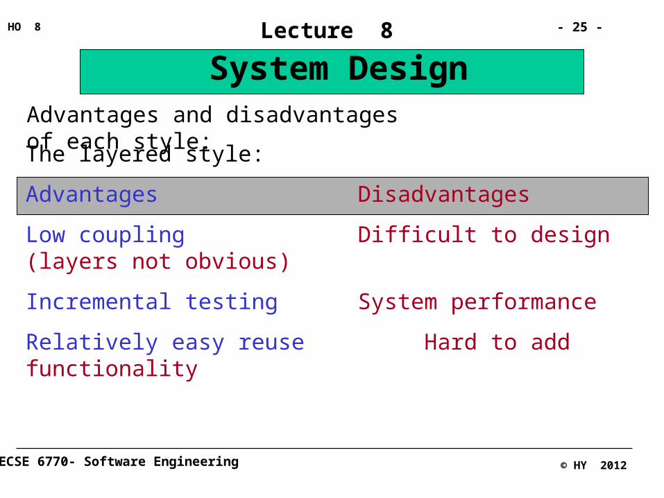
System DesignAdvantages and disadvantages of each style:
The layered style:
Advantages Disadvantages
Low coupling Difficult to design (layers not obvious)
Incremental testing System performance
Relatively easy reuse Hard to add functionality
ECSE 6770- Software Engineering
- 26 -HO 8
© HY 2012
Lecture 8
System Design
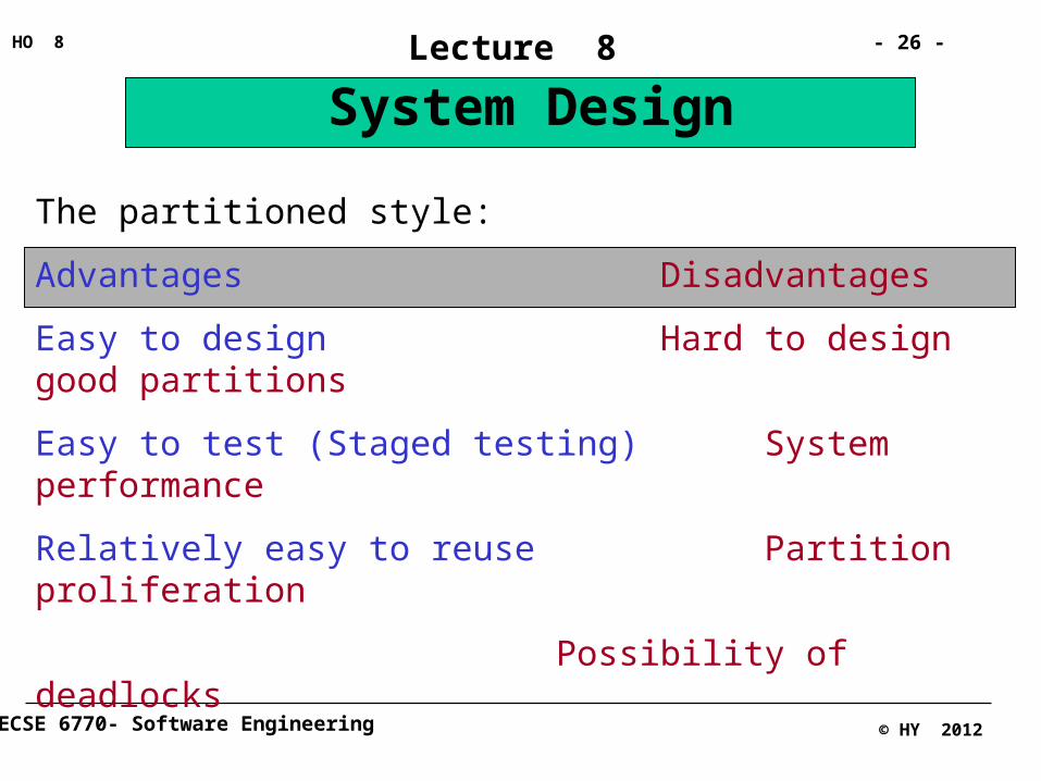
The partitioned style:
Advantages Disadvantages
Easy to design Hard to design good partitions
Easy to test (Staged testing) System performance
Relatively easy to reuse Partition proliferation
Possibility of deadlocks
ECSE 6770- Software Engineering
- 27 -HO 8
© HY 2012
Lecture 8
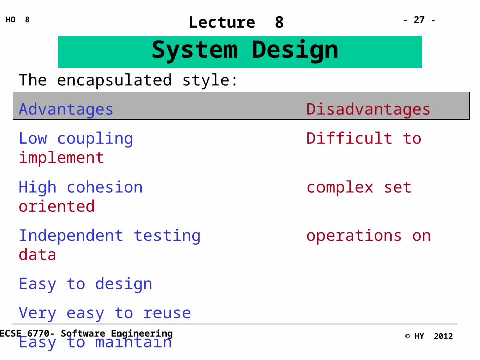
System DesignThe encapsulated style:
Advantages Disadvantages
Low coupling Difficult to implement
High cohesion complex set oriented
Independent testing operations on data
Easy to design
Very easy to reuse
Easy to maintain
System performance

ECSE 6770- Software Engineering
- 28 -HO 8
© HY 2012
Lecture 8
System DesignThe repository style:
Advantages Disadvantages
Set level data manipulation Relatively high coupling
Easy to design Difficult to test
Easy to add functionality Difficult to reuse
Easy to test Performance bottlenecks
Relatively easy to maintain
ECSE 6770- Software Engineering
- 29 -HO 8
© HY 2012
Lecture 8
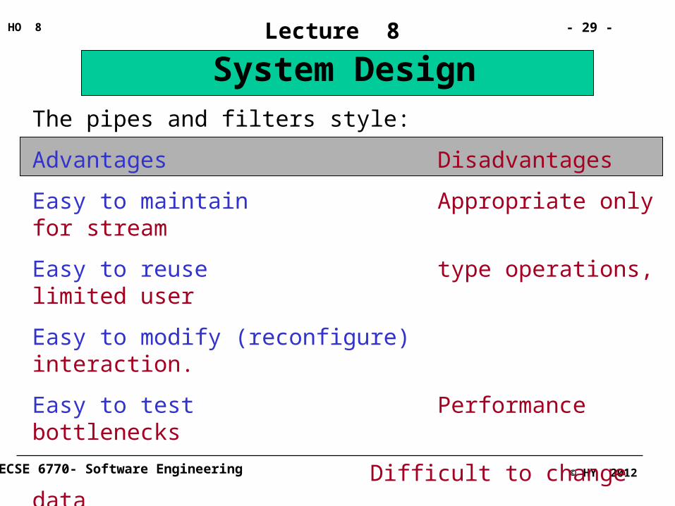
System DesignThe pipes and filters style:
Advantages Disadvantages
Easy to maintain Appropriate only for stream
Easy to reuse type operations, limited user
Easy to modify (reconfigure) interaction.
Easy to test Performance bottlenecks
Difficult to change data representation
ECSE 6770- Software Engineering
- 30 -HO 8
© HY 2012
Lecture 8
System DesignSolving specific architectural problems:
What went before was a treatment of some general architectural styles for software design. They can be used exclusively or in combination to arrive at a particular solution. In most cases a combination must be used as each segment of the problem lends itself to a particular architectural style. For example we might have a system that is composed of three partitions. The first partition might have been designed as three closed layers. Each layer might have a different architecture. The second partition might be a system of pipes and filters and the third a repository style architecture with encapsulated, event-driven clients around it.
However, there arise in software design specific , recurring problems
ECSE 6770- Software Engineering
- 31 -HO 8
© HY 2012
Lecture 8
System Design
that have recognized elegant solutions. Solutions that have worked extremely well in almost all situations before and therefore are likely to work well for your project, if you have the same problem to solve. Whilst it is impossible to present all possible specific design architecture patterns, we shall introduce a number of more general of these. For more, the reader is referred to the design architecture and patterns literature.
ECSE 6770- Software Engineering
- 32 -HO 8
© HY 2012
Lecture 8
System DesignParallelism for fault-tolerance
The basic idea behind this architecture is that system failure is a consequence of component failure. Thus by identifying the critical components of a system and taking steps to reduce the likelihood of failure in performing the task assigned to that component, we can reduce the chance of system failure. The traditional solution to this problem is to employ redundant components. For example a second latch on a trap door, in case the first would fail, or a reserve parachute. The same approach is taken in many fields of engineering. Many life or mission critical equipment such as satellites have a “hot stand-by” control mechanism to the primary control.
ECSE 6770- Software Engineering
- 33 -HO 8
© HY 2012
Lecture 8
System DesignEmployment of an identical multiple redundant system; that is exactly duplicating or multiplicating the same design component might be the answer to many problems of this nature. This might work with installing a duplicate metal shaft, an extra cable or plastic latch or even sometimes a second identical electronic circuit, but it unfortunately rarely works effectively in the case of software.
The reason is that physical components usually fail for different reasons, at different times at different places and sometimes with different consequences. For example if a metal shaft of a turbine breaks as a result of metal fatigue, it is unlikely that the back up shaft would also break at the same time, in the same location and as a consequence of metal fatigue. This is because most physical systems fail as a result of wear or load.
ECSE 6770- Software Engineering
- 34 -HO 8
© HY 2012
Lecture 8
System DesignWith logical systems this is rarely if ever the case. Software does not wear in the traditional sense, it sometimes behaves similarly to excess load as with physical systems but the main cause of failure in software is logical not physical. This means that if two components are identical, they will have the same logical defect in them. If a set of circumstances would cause the first to fail, it would most probably cause the second to fail in exactly the same way.
Therefore parallelism using identical components is of limited use with software.
Even in many physical systems the back-up redundant system is not of identical design to the primary. The “manual over-ride” on many electronics systems is a good example. These are two systems with
ECSE 6770- Software Engineering
- 35 -HO 8
© HY 2012
Lecture 8
System Designthe same functionality but vastly different designs. The likelihood of identical failure is reduced.
This is the approach usually taken with parallelism in software and is at the core of what is called the N-version architecture.
In this approach N different design versions are built - often by different design teams - based on the same specification. The assertion is that given the different design structure and implementation, it is unlikely that the different versions would contain the same defects leading to the same failures. Given this arrangement, usually all N versions operate in parallel and the output is sent to an output comparator which employs a comparison algorithm to reject the inconsistent output from the “failed” version.

ECSE 6770- Software Engineering
- 36 -HO 8
© HY 2012
Lecture 8
System DesignVersion 1
Version 2
Version 3Upstream Module
Output Comparator
The N-Version architectural styleUnfortunately however, the assertion that different design teams producing different designs are unlikely to end up with products containing similar logical faults has been vigorously challenged (Knight and Leveson, 1986; Brilliant et al, 1990). Despite this, N-version style remains the most favorite solution to the requirement for fault tolerance.
ECSE 6770- Software Engineering
- 37 -HO 8
© HY 2012
Lecture 8
System DesignFeedback/feedforward for process control
Process control is a very important and frequently occurring design problem for which computing is utilized. Process control is when a system is used to monitor the variables influencing a situation so that some output is kept at a specific point or within a specified range. The thermostat on air conditioning systems is a simple example of such a process control mechanism. Other examples are furnace control mechanisms for refineries or smelters, auto-pilot systems on aircraft, or cruise control on automobiles.
It turns out that in order to control the output of the process, one can take two alternate approaches these are reactionary or anticipatory.
ECSE 6770- Software Engineering
- 38 -HO 8
© HY 2012
Lecture 8
System Design
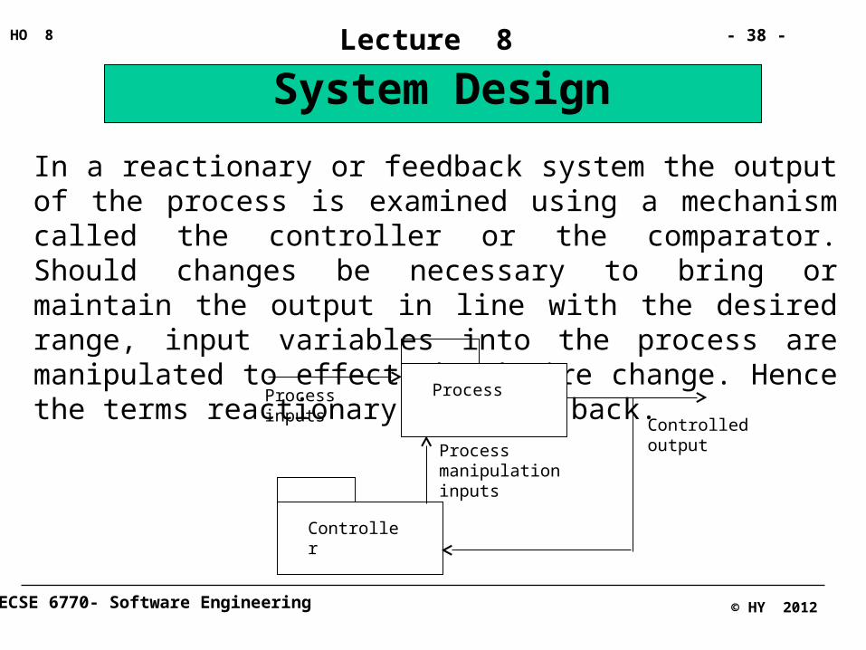
In a reactionary or feedback system the output of the process is examined using a mechanism called the controller or the comparator. Should changes be necessary to bring or maintain the output in line with the desired range, input variables into the process are manipulated to effect the desire change. Hence the terms reactionary and feed-back.
Process
Controller
Controlled output
Process manipulation inputs
Process inputs

ECSE 6770- Software Engineering
- 39 -HO 8
© HY 2012
Lecture 8
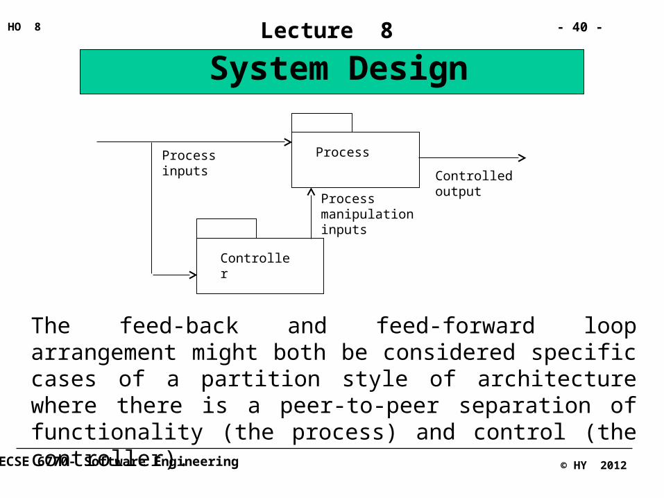
System DesignThe problem with a reactionary or feed-back system is that it takes time to react. There are situations in which by the time the output has been fed-back and measures have been taken to manipulate the system to bring it back into control, the damage is already done. In cases like that, we attempt to control the process by anticipating what change might be needed and make it in time for it to be effective. This is achieved through the feed-forward style. In a feed-forward loop, the input variables are fed through the controller. The controller rather than wait for the output, would examine historical data and inputs that are good indicators of what the output behavior might be and anticipate and effect the required manipulation. For example the current rate of flow of gas or the air/fuel mix ratio might be a good indicator of what the furnace temperature might be in one minute.
ECSE 6770- Software Engineering
- 40 -HO 8
© HY 2012
Lecture 8
System Design
Process
Controller
Process manipulation inputs
Process inputs
Controlled output
The feed-back and feed-forward loop arrangement might both be considered specific cases of a partition style of architecture where there is a peer-to-peer separation of functionality (the process) and control (the controller).

ECSE 6770- Software Engineering
- 41 -HO 8
© HY 2012
Lecture 8
System DesignBlackboards for pollingA blackboard is referred to a repository with central control flow. As we said before, in a blackboard, the state of a repository is used to trigger the peripheral sub-systems or modules. This makes blackboards an appropriate structures where there are alternatives in the peripheral modules to be activated based on the state of the repository (the blackboard). As the state of the blackboard changes, the appropriate peripheral modules respond, at times updating the repository and hence potentially changing its state. This change may then trigger another peripheral module and cause it to respond, and so on. An example might be an AI game playing system in which the decision as to what move algorithm to invoke is made based on the state of the game board (stored as the blackboard).

ECSE 6770- Software Engineering
- 42 -HO 8
© HY 2012
Lecture 8
System DesignMVC partitioning for user-interface independence
MVC stands for Model/View/Controller. The MVC architecture is a specific utilization of the partitioned style employed to separate the various components of a system. The three partitions are the:
Model: which maintains domain knowledge
View: which handles the interface of the system to the outside world
Controller: which handles the sequence interaction between the system and the user.
Alternatively, one might consider the model as a repository with the view and controller sub-systems as peripheral modules.
ECSE 6770- Software Engineering
- 43 -HO 8
© HY 2012
Lecture 8
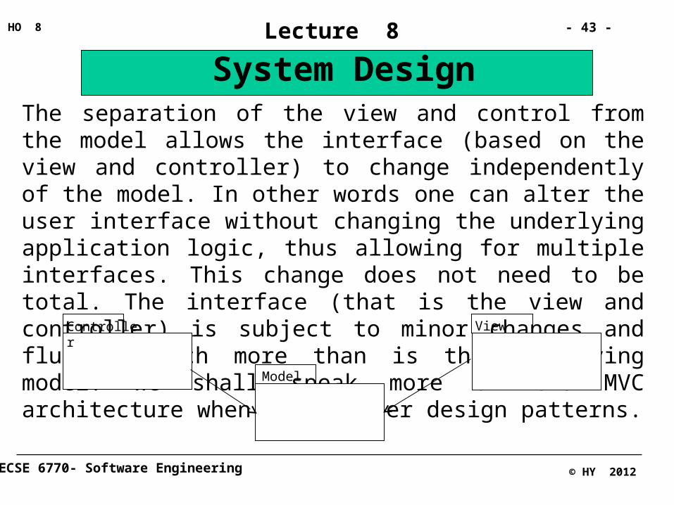
System DesignThe separation of the view and control from the model allows the interface (based on the view and controller) to change independently of the model. In other words one can alter the user interface without changing the underlying application logic, thus allowing for multiple interfaces. This change does not need to be total. The interface (that is the view and controller) is subject to minor changes and fluidity much more than is the underlying model. We shall speak more of the MVC architecture when we consider design patterns.
Controller
Model
View
ECSE 6770- Software Engineering
- 44 -HO 8
© HY 2012
Lecture 8
System DesignBasic steps for architectural design
There is no prescribed process for software system architecture design. In fact design (of anything) is a process that is very difficult to understand and model as it involves both procedural application of known facts and human ingenuity. Neither is design an isolated stage of the software process. It seems that the process of software construction involves tiny cycles of, “investigate a bit, analyze a bit, design a bit, code a bit, test a bit” with wild, opportunistically motivated jumps all over the place. However, there are a number of activities that have to be completed before the design is complete. Yet, most authors, taking an operational approach that takes into account a variety of system quality objectives, have provided heuristics and process prescriptions for the software design “Stage”.
ECSE 6770- Software Engineering
- 45 -HO 8
© HY 2012
Lecture 8
System DesignLooking at system quality requirements for a software product, it seems logical that:
In order to achieve a high level of functionality, we need to focus on the functional requirements
In order to achieve high levels of reliability, usability, maintainability, etc., we need to focus on the non-functional requirements
In order to implement concepts of good design such as modularity, etc., as discussed in the previous lecture, we need to decide on an initial overall topology (physical and logical) and architecture
Based on the overall architectural choices, we decide on sub-system organization, software/hardware mix and data transport mechanism.
ECSE 6770- Software Engineering
- 46 -HO 8
© HY 2012
Lecture 8
System DesignFor each major sub-system, we need to evaluate and select appropriate architectural styles.
In harmony with the architectural styles selected, we need to decide on strategies for persistent data storage and any and all middleware
Similarly, access and flow control policies must be selected
Availability of reusable software libraries that might assist with the economical implementation of the system must be considered and appropriate to-be-reused software “ear-marked”.
We need then to evaluate the design against all design criteria, stated or implied, particularly for overall feasibility, usability, reliability and economy and make any changes necessary.

ECSE 6770- Software Engineering
- 47 -HO 8
© HY 2012
Lecture 8
System DesignThus our list might read as something like:
1. Identify functional design goals from functional requirements
2. Identify other design goals from non-functional requirements
3. Decide on an overall coarse grain design topology
4. Identify sub-systems, also those available already as reusable components or legacy systems, and decide on a decomposition
5. Decide on Hardware/Software mix
6. Decide on inter-sub-system data transport mechanism
7. Based on 4,5, and 6, refine the overall design topology arrived at in 3 above and assign sub-systems to hardware platforms

ECSE 6770- Software Engineering
- 48 -HO 8
© HY 2012
Lecture 8
System Design8. For each sub-system evaluate and decide on an architectural style
9. Based on the above, decide on a strategy for persistent data storage and management
10. Decide on choice and use of middleware and distribution software
11. Decide on access control mechanisms and policies
12. Decide on an appropriate control flow mechanism
13. In view of all the above, and particularly item 4, identify and “earmark” reuse libraries.
14. Evaluate and revise the design based on quality criteria and design goals
ECSE 6770- Software Engineering
- 49 -HO 8
© HY 2012
Lecture 8
System Design
1
2 3
45
6
789
10111213 14
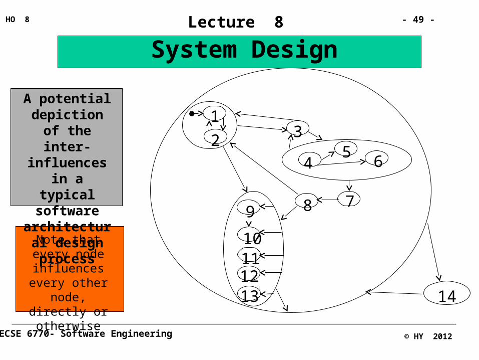
A potential depiction of the inter-influences
in a typical software
architectural design process
Note that every node influences
every other node, directly or otherwise
ECSE 6770- Software Engineering
- 50 -HO 8
© HY 2012
Lecture 8
System DesignActivities 1 and 2: Identifying functional and non-functional design goals:
We must clearly define design goals in terms of the specific project at hand. One major difficulty often encountered is that design goals are stated too generally and without clear definition and success criteria. Therefore:
For each quality factor important as a design goal (e.g. reliability) identify specific requirements as stated in the requirements document. Relate each to a design decision and define this relationship clearly. Include a measure or set of criteria for success.
ECSE 6770- Software Engineering
- 51 -HO 8
© HY 2012
Lecture 8
System DesignFor example:
In a missile system it is possible to:
a. Place the trajectory calculation software on board the missile, or
b. At the control base
Taking the approach suggested in (a) has the advantage of making the missile relatively independent of the launch base. All we need to do is to transmit to the missile the coordinates of the target and the trajectory will be calculated and adjusted by the missile itself. The disadvantage is that we need to place a sophisticated computer with lots of processing power and memory on-board.

ECSE 6770- Software Engineering
- 52 -HO 8
© HY 2012
Lecture 8
System DesignTaking the approach suggested in (b) requires a lot of communication with the launch base but will then allow the on-board system to be relatively simple by placing the trajectory calculation sub-system on the ground.
Now, the system requirements document says that the missile is to work in an environment where electromagnetic interference or interception might be a major issue. A generalization of requirement R-32-1 says that: “the missile shall calculate and retain a correct trajectory despite electromagnetic interference typical of combat situations”.
Requirement C-1-1 says that; “The overall cost of the system must be minimized”.

ECSE 6770- Software Engineering
- 53 -HO 8
© HY 2012
Lecture 8
System DesignThis creates a design challenge.
Leaving the trajectory sub-system on-board will satisfy requirement R-32-1 but will violate requirement C-1-1. The reason being that the cost of specialized on-board hardware to accommodate the trajectory calculation sub-system is very high whereas there is spare capacity at no cost at the launch base computer. What do we do?
Further study and referring the matter to the client ultimately results in a decision in favor of R-32-1.
An architectural design decision, one of logical and physical topology, is made. We opt for a client-server arrangement with a point-to-point physical topology with the server hardware on-board.

ECSE 6770- Software Engineering
- 54 -HO 8
© HY 2012
Lecture 8
System DesignWe are not finished yet.
We now need to ascertain – if not done before as we should have during the requirement phase – what constitutes “correct” calculation and retention of trajectory and what constitutes a “typical combat situation”. Only if our design decision can support the system under these conditions, is it a correct one to take. To do so we need to have knowledge of error margins allowed in the calculations to determine what is correct and what is not. We also need to assess the exact extent of electromagnetic stress or interception technology the client perceives to be at play and its impact on our systems. These considerations, in turn, have further hardware and software design (e.g. exception handling) ramifications.
ECSE 6770- Software Engineering
- 55 -HO 8
© HY 2012
Lecture 8
System DesignActivity 3; Decide on an overall coarse grain design topology
A first pass through all important design goals, (as per the previous two activities) should give us a basic idea of the physical topology of the system and the technologies and major software and hardware sub-systems involved. We need to depict this but be prepared to modify it based on further visibility.
For example we now know that we have a ground station computer, a transmitter/receiver system and an on-board computer. The on-board system is responsible for trajectory and attitude control. We need a sub-system to verify the correctness of communication between the two computers. The ground computer hosts the sub-systems to handle abort or re-assignment functionality etc.
ECSE 6770- Software Engineering
- 56 -HO 8
© HY 2012
Lecture 8
System DesignActivity 4: Identify sub-systems, identify those possibly available already as reusable components, or legacy systems and decide on a design decomposition.
Going down at least one level of granularity, we now need to identify the individual software sub-systems. We can do so through the employment of good design principles as discussed in the previous lecture.
For example
Maximize Cohesion:
Strive to have all components in the same sub-system be functionally related (functional or object cohesion).
ECSE 6770- Software Engineering
- 57 -HO 8
© HY 2012
Lecture 8
System Design
Usually classes extracted from the same use-case or closely related set of use-cases yield cohesive sub-systems.
Minimize Coupling:
Strive to have only a very small number of lines of communication or association cross between sub-systems.
You can play CRC (at multiple tables). In this variation, each person represents an object and each table represents a sub-system. Strive to keep the interaction on the same table and communication between the tables at a minimum. Modify the overall design topology if need be.
ECSE 6770- Software Engineering
- 58 -HO 8
© HY 2012
Lecture 8
System DesignWhy re-invent the wheel?
One major influencing factor on process efficiency is reuse. At this stage, it is possible to take into account the possibility of employing reusable components or legacy sub-systems. Depending on the balance of requirements, it may be prudent to allow the availability of sufficiently high quality reusable components to influence the design.
For example you might decide that you will use a particular already available and certified communication sub-system or object library to take care of the receive/transmit verification; one that has been successfully used in a similar system. Also a command legacy system is available that might be used.

ECSE 6770- Software Engineering
- 59 -HO 8
© HY 2012
Lecture 8
System DesignHaving arrived at a coarse level topology and the principal sub-systems of that topology, it is prudent to present each sub-system as an abstraction at THIS level of granularity. Amongst other benefits, this will much increase the understandability of the design. We can do so by abstracting each sub-system (including the legacy systems that might not be particularly modular. We shall see how this is done through the use of the façade or the adaptor design patterns) as if it were a single class with a given set of responsibilities (attributes and operations).
For example the communication verification sub-system might be presented as a class with the following operations only:
receive_communication (a_source) transmit_verified (a_destination)
ECSE 6770- Software Engineering
- 60 -HO 8
© HY 2012
Lecture 8
System DesignActivity 5: Decide on Hardware/Software mix
An old Japanese proverb says: “A person with only a hammer sees the entire world as nails”. Similarly not all design flexibility that can be implemented in software should be thus implemented. Often there is a decision to be made whether to solve a particular problem in hardware or in software. We must decide on this at some stage.
For example:
Error checking may be done via a software program or through the use of error checking hardware circuits. We need to decide what is appropriate for our particular situation.
ECSE 6770- Software Engineering
- 61 -HO 8
© HY 2012
Lecture 8
System DesignActivity 6: Decide on inter-sub-system data transport mechanism
It is best to isolate data transport or transport control mechanisms into separate sub-systems. This allows for flexibility when for example it is identified that one particular mechanism is not appropriate. This is particularly crucial when the system is highly distributed.
For example the communication verification and data transport facility of the missile system is best modeled as a separate sub-system.
Such separation in turn creates a design issue that is solved through the use of the proxy design pattern.
ECSE 6770- Software Engineering
- 62 -HO 8
© HY 2012
Lecture 8
System Design
Activity 7: Based on 4,5, and 6, refine the overall design topology arrived at in 3 above and assign sub-systems to hardware platforms
Before we have made any binding decisions regarding hardware platforms, we must review and refine the overall topology and ensure whether the topological organization as presented meets our requirements, particularly that it is workable, efficient and cost effective. This may result in a number of alterations in our design.
Playing CRC, client presentation and simulation are amongst the techniques that might assist at this stage.
ECSE 6770- Software Engineering
- 63 -HO 8
© HY 2012
Lecture 8
System DesignSelecting a hardware platform
Selecting a hardware platform is not merely deciding on the make and model of a particular piece of electronics. It entails considerations such as: Hardware certification and robustness, for example: is it tempested, can it operate at 5 degrees Kelvin, etc. Architecture: Is it vectorized, is it fault-tolerant at hardware level (redundant), is it a multi-processor, etc. Throughput and transaction processing capability, Operating capability, for example does it have multi-tasking and multi-processing ability, what is the size in bits of the machine word, Availability of specific software on that platform, particularly of operating systems, database management systems, compilers and middleware. Cost; Build or buy.
ECSE 6770- Software Engineering
- 64 -HO 8
© HY 2012
Lecture 8
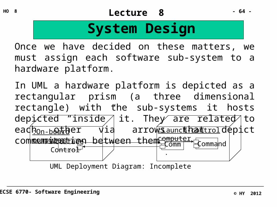
System DesignOnce we have decided on these matters, we must assign each software sub-system to a hardware platform.
In UML a hardware platform is depicted as a rectangular prism (a three dimensional rectangle) with the sub-systems it hosts depicted “inside” it. They are related to each other via arrows that depict communication between them.
:On-board computer :Launch-control computer
Attitude Control
Comm.
Command
UML Deployment Diagram: Incomplete
ECSE 6770- Software Engineering
- 65 -HO 8
© HY 2012
Lecture 8
System Design
Activity 8: For each sub-system evaluate and decide on an architectural style
It is now possible to consider an internal structure (an internal architecture) for each of our sub-systems. If need be we might continue the architectural decomposition one or two or more levels further before we are able to decide on what architectural style each module might have. As mentioned previously, certain design problems such as need for redundant operation or process control have established solutions, for the rest we would consider the best style or combination of styles that would fit.