edition 2002 catalog 2402 e - pawo- · pdf filedimensiones de las ranuras para chavetas uni...
TRANSCRIPT

CATALOG 2402 EEDITION 2002
Crowned and barrelled teeth gear couplingsZahnkupplungen mit balliger Verzahnung
Accouplements à denture bombéeAcoplamientos con engranajes de perfil y sección abombada

DISTRIBUTED BY - VERTEILT VON - DISTRIBUE PAR - DISTRIBUIDO POR
© Copyright - Poggi - 2002 - Italyall rights reserved
For the availability of products included in this catalogue, please consult us.This catalogue updates and replaces all previous editions. All specifications shown in this catalogue are representative only, and the right to makemodifications, without prior notice, is reserved. All specifications, photographs and drawings shall not be reproduced, in whole or in part, without ourprior written consent.
Für die Verfügbarkeit der in diesem Katalog angegeben Produkten, beraten Sie uns.Mit Erscheinen dieses Katalogs verlieren alle früheren ihre Gültigkeit. Alle Angaben in diesem Katalog sind freibleibend. Technische Änderungenbei Weiterentwicklung vorbehalten. Nachdruck (auch nur auszugsweise) nur mit unserer schriftlichen Genehmigung.
Pour la disponibilité des produits indiqués dans ce catalogue, merci de nous consulter.Ce catalogue met à jour et remplace toute édition précédente. Toutes les spécifications sont données à titre indicatif seulement, et sans aucunengagement de notre part.Nous nous réservons le droit de modifier ce catalogue sans aucun préavis, suivant l’évolution technologique. La reproduction, même partielle, desspécifications, des photos et des dessins ne peut pas être effectuée sans notre accord préalable, à donner par écrit.
Para la disponibilidad de los productos indicados en este catálogo, les rogamos nos consulten.Este catálogo pone al día y reemplaza todas las edicciones precedentes. Todas las informaciones sólo son indicativas y no implican ningún empeñopara nosotros.Nos reservamos el derecho de modificar este catálogo sin preaviso alguno, según la evolución tecnológica. La reproducción, aunque parcial, de lasinformaciones, fotografías y dibujos no puede hacerse sin nuestra autorización por escrito.
CATALOG 2402E - EDITION 2002 - PUBLISHED BY THE TECHNICAL DEPARTMENT OF POGGI® trasmissioni meccaniche s.p.a.

2
GDR gear couplings with nylon outer sleeveZahnkupplungen GDR mit Aussenteil aus NylonAccouplements type GDR à couronne en nylonAcoplamientos GDR con corona exterior de resinaDesign features:GDR couplings comprise of two externally toothed solid steel hubs coupled by means of a 6,6 polyamide nylon outer sleeve having internally mouldedteeth. The hub teeth are both crowned and barelled, to eliminate tooth edge pressures, to minimize tooth reactive forces and to provide for radial,angular and axial misalignment. The combination of steel and nylon tooth engagement provides a low friction characteristic resulting in freedom fromwear, lubrification, and maintenance. Continuous operating temperatures from -25C to +90C, with short peaks up to +125C, are permissable.
Produktbeschreibung:Die Kupplungen GDR bestehen aus zwei Naben aus Stahl. Sie sind an einem Ende verzahnt und durch einen innerverzahnten Kranz aus Polyamid6,6 verbunden. Die Kupplungen POGGI mit balliger Verzahnung finden vielfältige Anwendungen, besonders wenn Kupplungen gewünscht werden,die in alle Richtungen frei sind und keine Wartung erfordern. Mit diesen Kupplungen kann man problemlos radiale, winklige und axiale Versetzungender zu kuppelnden Wellen kompensieren, die auf Montagefehler oder Setzungen der Fundamente zuruckzuführen sind. Arbeitstemperatur von -25Cbis +90C, Spitzentemperatur von +125C.
Description:Les accouplements GDR sont costitués de 2 moyeux en acier, dentés aux extrémités, accéuplés par une couronne dentée en nylon polyamide 6,6denture interne. Les accouplements POGGI trouvent beaucoup d'applications chaque fois que l'on veut avoir de couplages libres en toute directionet qui ne demandent pas l'entretien. En effet, ces accouplements peuvent compenser aisement les désalignements radiaux, angulaires et axiaux desarbres à accoupler, causés par des fautes de montage ou des tassements de fondations. Temperatures continuelles de fonctionnement de -25C à+90C, avec un maximum de +125C.
Características constructivas :Los acoplamientos GDR están constituidos por dos cubos de acero dentados en la extremidad y conectados entre ellos por una corona de resinapoliamidica 6,6 dentada internamente. Los acoplamientos POGGI con engranajes de perfil y sección abombada encuentran aplicaciones múltiplescada vez que se quiera obtener acoplamientos libres en todas las direcciones y que no requieran mantenimento. Estos acoplamientos, en efecto,pueden compensar fácilmente desviaciones radiales, angulares y axiales de los ejes que deben acoplarse debidos a errores de montaje o a ajustesde las estructuras sobre la cuales están montados los órganos que deben conectarse. Temperatura de ejercicio continua desde -25C hasta +90C,con puntas max de +125C.
Explanation of the code for GDR couplings / Codierungserklärung der GDR KupplungenDéfinition du code pour les accouplements GDR / Definición del código para los acoplamientos GDR
Type Item nr. nylon sleeve Item nr. normal hub Item nr. extended hub Item nr. hub with bore (unbored) (unbored) and keyway
Typ Codierung Aussenteil aus Nylon Normal Nabe Verlängerten Nabe Normal Nabe Codierung(ungebort) (ungebort) mit Bohrungen Nut
Type Code couronne en nylon Code moyeu normal Code moyeu prolongé Code moyeu avec alésage(sans alésage) (sans alésage) et rainure
Tipo Código corona de resina Código cubo normal Código cubo prolongado Código cubo con taladro(sin taladro) (sin taladro) y ranura
GDR 0,6/14 24C14 24MN14 24MP14 24MN14..GDR 1,2/19 24C19 24MN19 24MP19 24MN19..GDR 2/24 24C24 24MN24 24MP24 24MN24..GDR 3,6/28 24C28 24MN28 24MP28 24MN28..GDR 6,5/38 24C38 24MN38 24MP38 24MN38..GDR 10/48 24C48 24MN48 24MP48 24MN48..GDR 19/55 24C55 24MN55 24MP55 24MN55..GDR 35/65 24C65 24MN65 24MP65 24MN65..
D b t
10 >>>>> D ≥≥≥≥≥ 12 4 D+1,812 » » » 17 5 D+2,317 » » » 22 6 D+2,822 » » » 30 8 D+3,330 » » » 38 10 D+3,338 » » » 44 12 D+3,344 » » » 50 14 D+3,850 » » » 58 16 D+4,358 » » » 65 18 D+4,465 » » » 75 20 D+4,975 » » » 85 22 D+5,485 » » » 95 25 D+5,495 » » » 110 28 D+6,4
Dimensions of keyways to UNI 6604-69 DIN 6885 / Abmessung der Keilnuten nach UNI 6604-69 DIN 6885Dimensions des rainurespour clavettes aux normes UNI 6604-69 DIN 6885Dimensiones de las ranuras para chavetas UNI 6604-69 DIN 6885
Note:We deliver our GDR couplings as separatecomponents. When ordering a coupling,please mention the codes of each part:For example:one GDR coupling type 3,6/28 with a normalhub + an extended hub:1) Nylon sleeve code 24C282) Normal hub code 24MN283) Extended hub code 24MP28
Note:Nous livrons nos accouplements GDR encomposants séparés.Pour commander un accouplement, veuillezindiquer les codes de chaque partie.Par exemple:un accouplement GDR type 3,6/28 avec unmoyeu normal + un moyeu prolongé:1) Couronne en nylon 24C282) Moyeu normal 24MN283) Moyeu prolongé 24MP28
Bemerkung:GDR Kupplungen sind als getrennte Teilegeliefert. Bei Bestellung bitte nennen Sie dieCodierung für jede Teile:Beispiel:1) Aussenteil aus Nylon 24C282) Normal Nabe 24MN283) Verlangte Nabe 24MP28
Nota:Se entregan los acoplamientos GDR encomponentes separados.Para pedir un acoplamiento, les rogamosindiquen los códigos de cada pieza.Por ejemplo:un acoplamianto GDR tipo 3,6/28 con un cubonormal y un cubo prolongado:1) Corona de resina2) Cubo normal 24MN283) Cubo prolongado 24MP28

3
GDR 0,6/14 50 57 64 25 12,5 25 23 41 2 4 30 11-14 0,200
GDR 1,2/19 54 69 84 28 13,0 32 25 50 2 4 40 11-14-19 0,380
GDR 2/24 65 85 105 30 17,5 38 30 60 3 5 50 14-19-24 0,580
GDR 3,6/28 85 105 125 35 25,0 43 40 70 3 5 60 19-22-24-28 1,030
GDR 6,5/38 105 135 165 40 32,5 56 50 82 3 5 80 24-28-32-38 2,090
GDR 10/48 106 166 226 45 30,5 64 50 92 4 6 110 32-38-42-48 2,650
GDR 19/55 138 183 228 55 41,5 80 65 112 5 8 110 38-42-48-55 5,600
GDR 35/65 169 229 289 60 54,5 95 80 134 6 9 140 48-55-60-65 9,700
GDR gear couplings with nylon outer sleeveZahnkupplungen GDR mit Aussenteil aus NylonAccouplements type GDR à couronne en nylonAcoplamientos GDR con corona exterior de resina
Type
Typ
Type
Tipo
A1 A2 A3 B C D E F G G1 M**
Standard coupling stock bores,bored to H7 and keywayed
Bohrungen H7 mit Nutab Lager lieferbar
Alésages H7 et rainure declavette de stock
Taladros H7 y chaveteroen stock
Weight
Gewicht
Poids
Peso
kg*
Dimensions table / Masstabelle / Dimensions / Dimensiones (mm)
Performance table / Leistungsdaten / Table technique / Table técnica
Type
Typ
Type
Tipo
TorqueDrehmoment
CouplePar
N/m
Pn
P=kW
}rpmUpmtpmrpm
n
Permissible kW power rating (rpm)
Leistung in kW bei Upm
Puissance en kW par tpm
Potencia transmisible en kW rpm
rpm
Upm
tpm
rpm
max
*Max misalingnment
Max Abweichung
Désalignementmaxi
Desviación max
Axialmisalignment
Axial-verschiebung
Déplacementaxial
Desplaza-mientoaxialnorm. max norm. max
norm. max norm. max norm. max norm. max norm. max500 750 1000 1500 3000
* The moment of inertia figures refer to standard couplings, bored to the maximum value shown on the dimensions table below.* Das Trägheitsmoment ist auf Kupplungen bezogen, die mit den maximal möglichen Bohrungen versehen sind.* Le moment d'inertie est calculé avec l'alésage maxi indiqué sur le tableau.* El momento de inercia se calcula con el agujero max indicado en la tabla.
* The weight refers to standard * Das Gewicht bezieht sich auf die * Les poids indiqués sont ceux des * El peso se aplica a loscouplings unbored. normale Kupplungen ohne Bohrung. accouplements non alésés. acoplamientos nonmales sin agujero.
**The extended hubs are available **Die verlangerten Naben sind ab **Les moyeux prolongés ne sont **Los cubos prolongados sonfrom stock, only unbored. Lager nur ohne Bohrung vorrätig. disponibles en stock que sans alésage. disponibles en stock solo sin agujero.
PD2
kg cm2
GDR 0,6/14 10 20 0,0010 0,0021 0,50 0,62 0,75 1,57 1,00 1,24 1,50 3,15 3,00 6,30 7000 0,28 ±2° ±0,4 ±1
GDR 1,2/19 16 32 0,0017 0,0033 0,85 1,65 1,27 2,47 1,70 3,30 2,55 4,95 5,10 9,90 7000 0,86 ±2° ±0,4 ±1
GDR 2/24 20 40 0,0020 0,0041 1,00 2,05 1,50 3,08 2,00 4,10 3,00 6,15 6,00 12,3 6000 1,43 ±2° ±0,5 ±1
GDR 3,6/28 45 90 0,0047 0,0094 2,35 4,70 3,52 7,05 4,70 9,40 7,05 14,1 14,1 28,2 6000 5,52 ±2° ±0,5 ±1
GDR 6,5/38 80 160 0,0083 0,0167 4,15 8,35 6,22 12,5 8,30 16,7 12,4 24,0 24,9 50,8 5500 21,38 ±2° ±0,5 ±1
GDR 10/48 138 276 0,0144 0,0289 7,20 14,4 10,8 21,6 14,4 28,9 21,6 43,3 43,2 86,7 5000 63,99 ±2° ±0,5 ±1
GDR 19/55 280 560 0,0290 0,0586 14,4 29,3 21,7 43,9 29,0 58,6 43,5 87,9 87,0 176 4000 117,00 ±2° ±0,6 ±1
GDR 35/65 385 770 0,0403 0,0806 20,1 40,3 30,2 60,4 40,3 80,6 60,4 121 121 242 3500 305,00 ±2° ±0,6 ±1

4
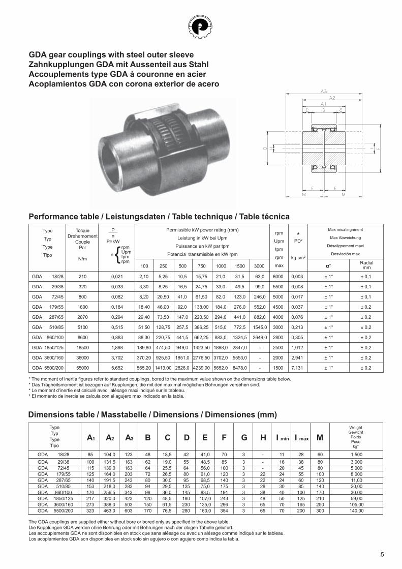
GDA gear couplings with steel outer sleeveZahnkupplungen GDA mit Aussenteil aus StahlAccouplements type GDA à couronne en acierAcoplamientos GDA con corona exterior de acero
Design features:GDA couplings comprise two externally toothed solid steel hubs coupled by means of a solid steel, internally toothed sleeve, sealed at each end bya single lip seal, retained by a circlip.The sleeve is machined from R 80-90 kg/mm2 grade steel, whereas the hubs are machined from carbon steel with high frequency hardened teeth.Both sleeve hubs are machined all over and can therefore be used for high speed applications, as the parts are in perfect dynamic balance.The hub teeth are both crowned and barelled and accurately machined to ensure that clearances between the meshing teeth are kept to a minimum,without limiting the flexibility requiered to accomodate radial, angular and axial shaft misalignment.GDA couplings require continuous lubrification by grease, which can be applied through the special grease plugs housed in the sleeve.The rubber lip seals, retained by circlips, ensure a positive seal to the sleeve chamber. Recommended alternative greases are shown on page 6.
Produktbeschreibung:Die Kupplungen GDA bestehen aus zwei an den Enden verzahnten Naben aus Stahl, verbunden durch einen innenverzahnten Kranz, auf dem dieDichtringe und Sicherungsringe angebracht sind.Der Kranz ist aus Stahl R 80-90 kg/mm2 hergestellt, die Verzahnung der Naben ist induktionsgehärtet.Die sehr präzise mechanische Fertigung und die laufenden Kontrollen, denen die Einzelteile unserer Kupplungen unterworfen werden, gewährleisteneine einwandfreie Funktion auch bei hohen Drehzahlen, so dass die typische Flexibilität beim Ausgleich von Radial -, Axial - und Winkelversetzungenvoll ausgenutzt werden kann.Die Kupplungen GDA müssen dauerhaft geschmiert werden.Dies geschieht mit Fett, das durch die dafür bestimmten Einfüllstopfen an dem Kranz eingefüllt wird.Als Dichtungen sind Ringe aus syntetischen Kautschuk eingesetzt, die durch Sicherungsringe axial gehalten sind. Die empfohlenen Fette, die allegleichwertig sind, sind aus der Tabelle auf Seite 6 ersichtlich.
Description:Les accouplements GDA sont costitués par 2 moyeux dentés aux extrémités, accouplés par une couronne dentée intérieurement sur laquelle on aassemblé les bagues d'étancheité et les bagues d'arret. La couronne est fabriquée en acier R 80-90 kg/mm2 et les moyeux en acier au carbonetrempés par induction.L'extreme précision d'usinage de leurs pièces constitutives ainsi que les fréquents contrôles auxquels elles sont soumises, garantissent à nosaccouplements un fonctionnement parfait, même à des vitesses de rotation élevées.Ceci permet de tirer entièrement profit de leur remarcable flexibilité lors de compensation de désalignements radiaux, axiaux ou angulaires. Lesbagues d'étanchéite utilisés sont du type radial, en caoutchouc synthétique, avec circlips pour leur fixation axiale.Les accouplements GDA doivent être lubrifiés en permanence.A cet effet, des graisseurs sont disposés sur la couronne.Les types de graisse recommandées, tous étant d'égale valeur, sont indiqués dans le tableau page 6.
Características constructivas:Los acoplamientos GDA se componen de dos cubos dentados en un extremo y unidos entre sí por una dolla dentada interiormente y con alojamientosprevistos para su fijación y montaje de retenes. La dolla está construida en acero R 80-90 kg/mm2 y los cubos son de acero al carbono y templadospor inducción en su parte dentada.La cuidadosa elaboración mecánica y los controles de calidad a los que están sometidos los componentes del acoplamiento GDA, permiten trabajara régimen elevado de giro así como la gran transmisión de par absorviendo las desalineaciones radiales y axiales que puedan existir.Los acoplamientos GDA deben ser lubricados periódicamente con grasa a través de los tapones que incorpora.Tabia de las grasas recomendadas a la pág. 6.
GDA 18/28 29C028 29MN028 29MP028GDA 29/38 29C038 29MN038 29MP038GDA 72/45 29C045 29MN045 29MP045GDA 179/55 29C055 29MN055 29MP055GDA 287/65 29C065 29MN065 29MP065GDA 510/85 29C085 29MN085 29MP085GDA 860/100 29C100 29MN100 29MP100GDA 1850/125 29C125 29MN125 29MP125GDA 3600/160 29C160 29MN160 29MP160GDA 5000/200 29C200 29MN200 29MP200
Type Item nr. steel sleeve Item nr. normal hub Item nr. extended hub
Typ Codierung Aussenteil aus Stahl Normal Nabe Codierung Verlängerten Nabe Codierung
Type Code couronne en acier Code moyeu normal Code moyeu prolongé
Tipo Código corona de acero Código cubo normal Código cubo prolongado
5
GDA 18/28 210 0,021 2,10 5,25 10,5 15,75 21,0 31,5 63,0 6000 0,003 ± 1° ± 0,1
GDA 29/38 320 0,033 3,30 8,25 16,5 24,75 33,0 49,5 99,0 5500 0,008 ± 1° ± 0,1
GDA 72/45 800 0,082 8,20 20,50 41,0 61,50 82,0 123,0 246,0 5000 0,017 ± 1° ± 0,1
GDA 179/55 1800 0,184 18,40 46,00 92,0 138,00 184,0 276,0 552,0 4500 0,037 ± 1° ± 0,2
GDA 287/65 2870 0,294 29,40 73,50 147,0 220,50 294,0 441,0 882,0 4000 0,076 ± 1° ± 0,2
GDA 510/85 5100 0,515 51,50 128,75 257,5 386,25 515,0 772,5 1545,0 3000 0,213 ± 1° ± 0,2
GDA 860/100 8600 0,883 88,30 220,75 441,5 662,25 883,0 1324,5 2649,0 2800 0,305 ± 1° ± 0,2
GDA 1850/125 18500 1,898 189,80 474,50 949,0 1423,50 1898,0 2847,0 - 2500 1,012 ± 1° ± 0,2
GDA 3600/160 36000 3,702 370,20 925,50 1851,0 2776,50 3702,0 5553,0 - 2000 2,941 ± 1° ± 0,2
GDA 5500/200 55000 5,652 565,20 1413,00 2826,0 4239,00 5652,0 8478,0 - 1500 7,131 ± 1° ± 0,2
GDA gear couplings with steel outer sleeveZahnkupplungen GDA mit Aussenteil aus StahlAccouplements type GDA à couronne en acierAcoplamientos GDA con corona exterior de acero
Dimensions table / Masstabelle / Dimensions / Dimensiones (mm)
Performance table / Leistungsdaten / Table technique / Table técnica
Type
Typ
Type
Tipo
TorqueDrehemoment
CouplePar
N/m
Permissible kW power rating (rpm)
Leistung in kW bei Upm
Puissance en kW par tpm
Potencia transmisible en kW rpm
rpm
Upm
tpm
rpm
max
PD2
kg cm2
*Max misalingnment
Max Abweichung
Désalignement maxi
Desviación max
100 250 500 750 1000 1500 3000
* The moment of inertia figures refer to standard couplings, bored to the maximum value shown on the dimensions table below.* Das Trägheitsmoment ist bezogen auf Kupplungen, die mit den maximal möglichen Bohrungen versehen sind.* Le moment d'inertie est calculé avec l'alésage maxi indiqué sur le tableau.* El momento de inercia se calcula con el agujero max indicado en la tabla.
ααααα° Radialmm
Pn
P=kW
}rpmUpmtpmrpm
n
The GDA couplings are supplied either without bore or bored only as specified in the above table.Die Kupplungen GDA werden ohne Bohrung oder mit Bohrungen nach der obigen Tabelle geliefert.Les accouplements GDA ne sont disponibles en stock que sans alésage ou avec un alésage comme indiqué sur le tableau.Los acoplamientos GDA son disponibles en stock solo sin agujero o con agujero como indica la tabla.
GDA 18/28 85 104,0 123 48 18,5 42 41,0 70 3 - 11 28 60 1,500GDA 29/38 100 131,5 163 62 19,0 55 48,5 85 3 - 16 38 80 3,000GDA 72/45 115 139,0 163 64 25,5 64 56,0 100 3 - 20 45 80 5,000GDA 179/55 125 164,0 203 72 26,5 80 61,0 120 3 22 24 55 100 8,000GDA 287/65 140 191,5 243 80 30,0 95 68,5 140 3 22 24 60 120 11,00GDA 510/85 153 218,0 283 94 29,5 125 75,0 175 3 28 30 85 140 20,00GDA 860/100 170 256,5 343 98 36,0 145 83,5 191 3 38 40 100 170 30,00GDA 1850/125 217 320,0 423 120 48,5 180 107,0 243 3 48 50 125 210 59,00GDA 3600/160 273 388,0 503 150 61,5 230 135,0 296 3 65 70 165 250 105,00GDA 5500/200 323 463,0 603 170 76,5 280 160,0 354 3 65 70 200 300 140,00
TypeTypTypeTipo
A1 A2 A3 B C D E F G H I min I max M
WeightGewicht
PoidsPesokg*

6
MOBIL GULF SHELL AGIP IP BP TOTAL ESSO
Mobilplex Gulfcrown EPO Simnia grease O GRMU EPO Atina grease O Grease LTX-EPO Multis EP 01 Beacon EPO
ASSEMBLY OF GDA COUPLINGS1) Place circlip (item 1) and lip seal (item 2) carefully over each shaft,
taking care not to damage the seal lip.2) Mount the hubs (item 3) onto their relative shafts until the inner face
of the hub is flush with the end of the shaft.3) Determine the longest shaft and slide the sleeve (item 4) right
through the hub teeth until the end of the sleeve is beyond the shaftend.
4) Bring the two shafts together until gap G equals the value specifiedin the dimensions table.
5) Line up the two shafts and check that the parallel and angularalignment figures are within the values specified.
6) Coat the hub teeth and hil the hub gap with the recommended typeof grease as shown in the table. Lightly coat hub diameters withgrease to ensure lip seal slides smoothly over hub diameter.
7) Slide the sleeve (item 4) back into position over both sets of hubteeth. Locate the lip seals (item 2) into each end of the sleeve.Ensure the lip seals are fully seated and snap the circlip (item 1)into sleeve grooves.
8) To dismantle coupling, remove the circlips (item l) using suitablecirclip pliers and slide the sleeve off the hubs (itern 3) the sametime ejecting the lip seal (item 2) via the ends of the hub teeth.
MONTAGE DER KUPPLUNGEN GDA1) Den Sicherungsring (l) und den Dichtring (2) auf jede der
beiden zu kuppelnden Wellen auflegen.2) Die Naben (3) auf die entsprechenden Wellen montieren.3) Der Kranz (4) kommt auf die längere Welle.4) Die Wellen zusammenbringen und kontrollieren, ob der
Zwinschenraum G dem in der Tabelle angegebenen Wertentspricht.
5) Die Flucht und die Parallelität der Welle kontrollieren.Anschliessend die Naben auf der Welle befestigen.
6) Die Verzahnung und den Raum zwischen den Naben mit Fettfüllen (siehe Tabelle der empfohlenen gleichwertigen Fette).
7) An dieser Stelle der Montage den Kranz (4) an seinen Platzverschieben, die Dichtringe (2) anbringen und dieSicherungsringe in ihre Nuten montieren.
8) Zum Abmontieren: die Sicherungsringe (1) mit Zangeabnehmen, den Kranz (4) von den Naben (3) enffernen unddie Kupplung GDA ist vollständig demontiert.
ASSEMBLAGE DESACCOUPLEMENTS GDA1) Mettre les bagues d'arrêt (l) et les bagues d'étancheité sur
chaque arbre à accoupler.2) Glisser les moyeux (3) sur leurs arbres respectifs.3) Pousser le manchon (4) sur l'arbre le plus long.4) Approcher les moyeux en contrâlant que l'espace G corréspond
à la valeur donnée sur le tableau des dimensions.5) Aligner les arbres en contrâlant le parallèlisme, fixer le moyeux.6) Mettre de la graisse (voir tableau) sur la denture et dans
l'espace entre les moyeux.7) Glisser la manchon (4) jusqu'à son emplacement, introduire les
bagues d'étancheité (2) dans leurs logements et mettre enplace les bagues d'arret (1).
8) Pour démonter l'accouplement, enlever les bagues d'arrêt (l) àl'aide d'une pince, séparer le manchon (4) des moyeux (3), etvotre accouplement est demonté.
INSTALACIÓN DE LOSACOPLAMIENTOS GDA1) Meter el anillo de parada (1) y el anillo de hermetcidad (2)
sobrelos dos ejes que deben ser acoplados.
2) Montar los cubos (3) sobre los respectivos ejes.3) La corona (4) va colocada sobre el eje más largo.4) Acercar los ejes y controlar que el espacio G sea el de la tabia.5) Alinear los ejes y controlar el paralelismo, después fijar los
cubos al eje.ó) Llenar de grasa (ver tabla de las grasas aconsejadas) el
engranaje y la cámera entre los cubos.7) A este punto para montar hacer deslizar la corona (4) a su sitio
introducir los anillos de hermeticidad (2) y fijar los anillos deparada (l) en su sede.
8) Para desmontar quitar con la pinza los anillos de parada (l)separar la corona (4) de los cubos (3) y el acopliamentoGDA está completamente desmontado.
Maintenance:
Unscrew both plugs (5). Keeping thegrease holes in a horizontal planeinject grease with a grease gun, intoone of the holes until some greasecomes out of the hole on the otherside.Then screw back the plugs. Thisoperation has to be repeated every1000 working hours.
Wartung:
Beide Einfüllstopfen (5) abschrauben,dann mit Fettpresse Fett einfüllen, bises aus dem anderen um 180°versetzen Loch wieder austritt, wobeidie Schmierbohnungen aufhorizontaler Ebene liegen müssen.Beide Einfüllstopfen wieder ein-schrauben. Nach 1000Betriebsstunden die Schmierungwiederholen.
Recommended grease types / Fettsortetabelle / Graisses conseillées / Grasas recomendadas
Entretien:
Dévisser les 2 vis bouchons (5),positionner les 2 trous de graissage surun plan horizontal, injecter la graisse àl'aide d'une pompe jusqu’au momentoù elle débordera dans le trou opposé.Cette opération est à renouveler toutesles 1000 heures de fonctionnement.
Mantenimiento:
Desatomillar ambos tapones (5)después con los orificios deengrasado sobre un plano horizontalintroducir grasa con el engrasadorhasta que no sobresalga por el otroorificio a 180°. Montar los tapones.La operación debe ser repetida cada1000 horas de trabajo.

7
COUPLING SELECTION
For quick selection (simple drive applications)
A) Divide the transmitted kW by the minimum rpm appllied tothe coupling and choose a coupling size from the performan-ce table which give a P/n ratio just larger than the kW/rpmcalculated.
B) Make sure that the shaft diameters of both machines arewithin the maximum and minimum permissable bores shownin the dimensions table for the selected coupling. If one orother of the shaft is larger, then select an appropriate largercoupling.
For more accurate selection (high shock and irregulardrive applications)
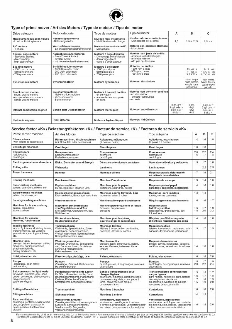
1) Determine whether the type of prime mover falls intocategory A, B, or C in the table in the next page.
2) Select the type of driven machine and align with the drivecategory column to determine the service factor K from thetable below.
3) Calculate the maximum torque to be transmitted Mt byapplying the following formula:
4) Check that the shaft diameters of both machines are withinthe maximum and minimum coupling bores shown in thedimensions table. If one or other of the shaft is larger, thenselect an appropriate larger coupling.
Mt = 9550 • P • Kn
AUSWAHL DER KUPPLUNG
A) Für die Vorauswahl, welche Kupplung gebraucht wird, istdarauf zu achten, dass das Verhältnis P/n oder die Leistungbei der gewünschten Drehzahl kleiner ist, als die in derTabelle angegebenen Werte für die gewählte Kupplung.
B) Nachprüfen, ob die Maximalbohrungen der gewähltenKupplung für die vorhandenen Wellen ausreichen.
1) Für eine genaue Berechnung müssen die zu übertragendeLeistung Motorart und Betriebsbedingungen bekannt sein.
2) Je nach Art der Maschine, der Motorklasse und denBetriebsbedingungen wird der Belastungsfaktor K nach denTabellen bestimmt.
3) Das von der Kupplung zu obertragende Drehmoment Mt wirdnach der folgenden Formel berechnet:
4) Die Kupplung wählen, bei der das maximale übertragbareDrehmoment grösser als der ermittelte Wert ist.
5) Nachprüfen, ob die Maximalbohrung der gewahlten Kupplungausreichend ist.
Mt = 9550 • P • Kn
CHOIX DE L'ACCOUPLEMENT
A) Pour un calcul rapide du choix de l'accouplement, on doitvérifier que le rapport P/n ou la puissance aux tours quiintéressent soit inférieur aux données normales du tableau etchoisir l'accouplement correspondant.
B) Contrôler que les moyeux de l'accouplement choisipermettent l'alésage demandé, autrement passer àl'accouplement supérieur.
1) Pour un calcul plus exact, il faut connaître la puissancetranmise, le type et la catégorie du moteur.
2) Suivant le type de la machine sur laquelle est montél'accouplement, la condition de travail et la classe du moteur,définir le facteur de service.
3) Calculer le couple à transmettre Mt avec la formule:
4) Choisir l'accouplement qui a un couple maxi transmissiblesupérieur à celui ainsi défini.
5) Côntroler que les moyeux de l'accouplement choisipermettront l'alésage demandé, autrement passer àl'accouplement supérieur.
Mt = 9550 • P • Kn
SELECCIÓN DEL ACOPLAMIENTO
A) Para un cálculo rápido de la selección del acoplamiento,verificar que la relación P/n, o la potencia a los giros queinteresan sea inferior a los datos normales de la tabla yseleccionar el acoplamiento correspondiente.
B) Averiguar que los cubos del acoplamiento seleccionadopermitan el agujero solicitado, si no, pasar al acoplamientomayor.
1) Para un cálculo más exacto es necesario conocer la potenciatransmitida, el tipo y la categoría del motor.
2) Basándose en la maquina sobre la que se instalará elacoplamiento, en las condiciones de trabajo y en la clase delmotor, definir el factor de servicio.
3) Calcular el momento de torsión Mt que tiene que sertransmitido, con la formula:
4) Seleccionar el acoplamiento que tiene un momento detorsión max transmisible superior a lo que se definido.
5) Controlar que los cubos del acoplamiento seleccionandopermitan el agujero solicitado, si no, pasar al acoplamientomayor.
Mt = 9550 • P • Kn
Mt = couple en NmP = puissance installée en kWn = tpm de l'accouplementK = facteur de service
Mt = momento de torsión en NmP = potencia instalada en kWn = rpm del acoplamientoK = factor de servicio
Mt = Drehmoment in NmP = installierte Leistung in kWn = Upm der KupplungK = Belastungsfaktor
Mt = torque in NmP = power installed in kWn = rpm of couplingK = service factor
8
Type de machineAgitateurs, mélangeurs(à pale ou hélice)
Centrifugeurs
Compresseursalternatifscentrifuges
Générateurs électriques et excitateurs
Laminoirs
Marteaux-pillons
Machine d’imprimerie
Machines pour le papieragitateurs, calandres, mixers
Machines pour le travail du boistournante, scies, à ruban
Machines à laver pour blanchisserie
Machines pour briquetterie et l’argileforeuses, broyeurs etc.pressoirs
Machines pour les pâtes,pour mélanger le caoutchouc
Machines textilesMétiers à tisser, à filer, ourdissoirs,bobinoirs, dévidoirs, cardes
Machines-outilspresses, tours, brocheuses, perceu-ses, rectifieuses, fraiseuse, étauxlimeurs
Palans, élévateurs
Pompescentrifugeuses, à engrenages, rotativesalternatives
Bandes transporteuses pourcharges légèrespour fours, minéraux, charbons-sableconvoyeurs à godets, convoyeurs àlame, convoyeurs de dragueconvoyeurs à vis
Machines à trancher
Machines à cribler
Ventilateurs, aspirateursaspirateurs, centrifugeurs à courantd’air forcé, propulseurs, ventilateurs pourles mines, compresseurs volumétriques
C1,8
2,41,8
1,8
2,5
2,1
1,6
1,8
1,7
1,92,2
1,8
1,9
1,8
2,0
1,92,4
1,71,81,92,0
2,0
2,0
C
2,5 ÷ 4
15÷11 kW1,5÷7,5 kW0,7÷3,6 kW
high torquehohes Drehm.couple elevé
par alto
5 cyl. or <5 zyl. oder >
5cyl. ou >5 cil.o >
Type of prime mover / Art des Motors / Type de moteur / Tipo del motor
Drive categoryMax istantaneous peak values- Load multiuivinq factors
A.C. motors- 1-phase
Squirrel cage motors- Star/delta starling- direct starting- high static torque
Slip ring motors- 1500 rpm or more- 950 rpm or more- 750 rpm or more
Synchronous motors
Direct current motors- shunt -wound motors- compound-wound motors- series-wound motors
Internal combustion engines
Hydraulic engines
MotorkategorieHöchste Spitzenwerte- Belastungsfaktor
Wechselstrommotoren- Einphasenwechselstrommotoren
Kurzschlussläufermotoren- Stern/Dreieck Anlauf- direkter Anlauf- mit hohem Anlaufdrehmoment
Schleifringläufermotoren- 1500 Upm oder mehr- 950 Upm oder mehr- 750 Upm oder mehr
Synchronmotoren
Gleichstrommotoren- Nebenschlussmotoren- Verbundmotoren- Serienmotoren
Benzin oder Dieselmotoren
Hydr. Motoren
Type de moteurNiveaux maxi instantanés- Multiplicateurs de charge
Moteurs à courant alternatif- Monophasé
Moteurs à cage d'écureuil- Démarrage étoile/triangle- démarrage direct- couple à arrêt statique
Moteurs à collecteur- 1500 tpm et plus- 950 tpm et plus- 750 tpm et plus
Moteurs synchrones
Moteurs à courant continu- en derivation- à enroulement composé- en série
Moteurs thérmiques
Moteurs hydrauliques
A
1,5
8 cyl. or >8 zyl. oder >8 cyl. ou >8 cil.o >
B
1,5 ÷ 2,.5
15 kW ≤11 kW ≤5,5 kW ≤
stand torquenorm. Drehm.couple norm.par normal
6 cyl.6zyl.6cyl.6 cil.
Service factor «K» / Belastungsfaktoren «K» / Facteur de service «K» / Factores de servicio «K»Prime mover machineStirres, mixers(with blades or screws) etc.
Centrifugal machines
Compressorsreciprocatingcentrifugal
Electric generators and exciters
Rolling mills
Power hammers
Printing machines
Paper-making machinesstirrers, calenders, mixers, etc.
Wood working machineslathes, band-saws, etc.
Laundry washing machines
Machines for bricks and clayaugers, granulatorsstone crushers
Machines for «pasta»factories, rubber mixer
Textiles machineslooms, fly frames, doubling frames,warping frames, coil winders,yam winders, carding machines,etc.
Machine toolspresses, lathes, broaches, drillingmachines, rinding machines,shaping machines,milling machines, etc.
Hoist, elevators, etc.
Pumps-centrifugal, gear, rotaryreciprocating
Belt conveyors for light loadsfor ovens, minerals, coal, sandbucket conveyors, slat conveyorsdrag conveyorsscrew conveyors
Cutting-off machines
Sifting machines
Fans, ventilatorscentrifugal ventilators with forceddrat, propellers, extractor formines,positive displacementblowers
Art des MotorsRührmaschinen, Mischmaschinen(mit Schaufeln oder Schrauben)
Zentrifugen
KompressorenKolbenkompressorenKreiselkompressoren
Elektr. Generatoren und Erregen
Walzwerke
Hämmer
Druckmaschinen
PapiermaschinenRüher, Kalander, Mischer, usw.
HolzbearbeitungsmaschinenDrechselbänke, Bandsägemaschinen
Waschmaschinen
Maschinen zur Bearbeitungvon Ziegelsteinen und TonMeisselbohrer, Granulatoren, usw.Steinbrecher
Bäckereimaschinen,Kautschukmischer
TextilmaschinenWebstühle, Spindelbänke, Zwim-maschinen, Kettenmaschinen,Wickel-maschinen, SpülmaschinenKrempelmaschinen, usw.
WerkzeugmaschinenPressen, Drehbänke, Spindelpres-sen, Bohrmaschinen, Schleifma-schinen, Fräsmaschinen,Feilmaschinen, usw.
Flaschenzüge, Aufzüge, usw.
PumpenZentrifugal, Zahnrad, DrehpumpenHubkolbenpumpen
Förderbänder für leichte Lastenfür Öfen, Mineralien, Kohle, SandBecherkettenförderer, Plattenband-förderer, PlattenbandördererKratzförderer, Schneckenförderer
Trennmaschinen
Sichtmaschinen
Ventilatoren, EntlüfterZentrifugalentlüfter mit erzwungenemLuftstrom, Schraubenentlüfter,Ventilatoren für Bergwerke,Verdrängerkompressoren
A1,4
1,6
2,01,6
1,5
1,7
1,3
1,4
1,3
1,6
1,51,8
1,4
1,5
1,4
1,6
1,52,0
1,31,61,71,5
1,6
1,4
1,6
B1,6
1,8
2,21,7
1,7
2,2
1,9
1,4
1,6
1,4
1,6
1,72,0
1,6
1,7
1,6
1,8
1,72,2
1,51,71,81,9
1,8
1,5
1,8
For continuous running of 16 to 24 hours a day, add 0,1 to the service factor / Pour un nombre d’heures d’utilisation par jour de 16 jusqu’à 24 veulillez appliquer un facteur de corréction de 0,1 Für tägliche Betriebsdauer über 16 bis 24 Stunden: zusätzlicher Faktor + 0,1 / Para ún numero de horas de trabajo al día desde 16 hasta 24, considerar un factor de corrección de 0,1
Tipo máquinaAgitadores, mezcladores(a palas o a hélice)
Centrífugas
Compresoresalternativoscentrifugos
Generadores eléctricos y excitadores
Laminadores
Máquinas para la deformaciónen caliente de materiales
Máquinas de estampa
Máquinas para el papelagitadores, calendrias, mezcladores
Máquinas para maderatornos, sierras continuas
Máquinas generales para lavandería
Máquinas paraladrillos y arcillastaladradores, granuladores, ecc.trituradores
Máquinas para fábricas de pastasalimenticias, mezcladores para goma
Máquinas textilestelares torcederos, urdideras, bobi-nadoras, devanadoras, cardadoras
Máquinas herramientaspresas, tornos, balancines, taladros,rectificadoras, fresadoras, limadoras
Poleas, elevadores
Bombascentrífugas, de engranajes, rotativasalternativas
Transportadores continuos concargas ligeraspara homos, minerales, carb. harenade cangilones, de placasen cadena elevadores de paletasrascantes de roscas sin fin
Contadoras
Cernadoras
Ventiladores, aspiradoresaspiradores centrifugas con corrientede aire inducida, hélices, ventiladoresmina, compresores volumétricos
Tipo del motorNiveles máximos instántaneos- Multiplicador de la carga
Motores con corriente alternada- Monofase
Motores con jaula de ardilla- arranque estrella/triángulo- arranque directo- alto par de despunte
Motores de anillon- 1500 rpm o más- 950 rpm o más- 750 rpm o más
Motores sincrónicos
Motores con corriente continua- en derivación- execpto compuesta- en serie
Motores endotérmicos
Motores hidráulicos