edm 700/800 pilots guide - j.p. instruments s guide engine data management edm-700 edm-800 edm-711...
TRANSCRIPT

Pilot’s GuideEngine Data Management
EDM-700
EDM-800
EDM-711 Primary
Copyright 2000-2007 J.P. Instruments, Inc.
All Rights Reserved
J.P. INSTRUMENTS INC.
Information: P. O. Box 7033Huntington Beach, CA 92646
Factory: 3185 B AirwayCosta Mesa, CA 92626
(714) 557-5434 (800) 345 4574
Fax (714) 557-9840
www.jpinstruments.com
www.jpitech.com
www.BuyJPI.com
Printed in the United States of America Rev W 3/2009
Last printed 10/17/2012 9:05:00 PM

Table of Contents
Section 1 - Introduction 1Product Features 1Engine Data Management 2Benefits of Proper Mixture Control 2JPI Probes 2Temperature and Mixture 2
Section 2 - Displays and Controls 4Displays 4Modes 7Buttons 8Parameter Scan— EDM-700 without Fuel Flow Options 9Automatic Parameter Scan—EDM-711 10
Section 3 - Operating Procedures 11Diagnostic Testing on Startup and During Flight 11Modes 11Automatic Mode 11Manual Mode 12LeanFind Mode—Leaning Rich of Peak 12LeanFind Procedure—General Explanation 13Operation for each Phase of Flight 18Shock Cooling 19Common Misapplications 20
Section 4 - Diagnosing Engine Problems 21Alarms 24Pre-Ignition and Detonation 25
Section 5 - Fuel Flow Option Operation 26Fuel Flow Display Select Switch 26Fuel Management 28Parameter Scan—Systems with Fuel Flow Option 28
Section 6 - Long Term Data Memory 30Downloading from Long Term Memory 31Downloading Data from the EDM to a Flash Drive 31Downloading from USB Flash Drive to a PC 33
Section 7 - Personalizing 33Pilot Programming 33
Section 8 - Programming the EDM-800 Horsepower Constant 35Section 9 - Programming Manifold Pressure (MAP) 35Section 10 - Programming use of Factory Original TIT Probe 36Section 11 - Programming the Fuel Flow Option 38
Fuel Flow Option Programming Procedure 40Section 12 - Programming Long Term Data Memory 40Section 13 - EDM-711 Primary Alarm Display 41Section 14 - Alarm Limits 42
MAP, Fuel Flow Alarm Limits, Units, Fuel Capacity 44

Navigation Data Formats 46GPS-C Fuel Flow Format for GPS Bi-directional Comm 46Diagnostic Messages, Fuel Flow 47Navigation Data Ports for GPS Comm 47
Section 15 - Option Connector Pin Assignments 48Section 16 - Reference Reading 49Section 17 - Technical Support 49Limited Warranty 50Index 51
How to Change Modes (page 7)
EDM-700 enters Automatic mode two minutes after power up
AUTO INDEXparameters
automaticallyindexed
MANUAL INDEXparameters
indexed whenstep in tapped
Toggle to include/exclude
parameter inindexing
LEAN FINDstarts LeanFind
procedure
Toggle betweenLEAN R and
LEAN L of peak
dot flashessee
LEANEST
Displayspeak EGT
value
tap STEP button
tap LF, then tap STEP
tap STEP andLFsimultaneously
release buttons
LFLF
STEP
holdboth
STEP
andLF
simulta
neouslybeginleaning continue
leaninghold LF
releaseLF
In Lean of peak, after firstLeanFind, LF will return to theinverted bar graph. Tap LF again tostart LeanFind procedure


For Your Safe Flight Page 1
Section 1 - Introduction
Product Features
indicates standard feature 700 711 800Hands-free, automatic scanning (711: primary only)
All programming done from the Front Panel
LeanFind finds the first and last cylinder to peakwith true peak detect—eliminates a false peaks
Displays both leaned temperature below peak and peak
Battery voltage with alarm
24 Programmable alarm limits
Normalize view
DIF low to high EGT with alarm
EGTs to stable 1°F resolution
Shock cooling monitored on every cylinder
User selectable index rate
Fast response probes
Non-volatile long term memory
Records and stores data up to 30 hours
Post-flight data retrieval
Data retrieval software
FAA Approved as primary temperature instruments forCHT, OIL, TIT
Alarm and warning light panel
Oil temperature opt optTurbine inlet temperature opt opt optOutside air temperature opt opt
Compressor discharge temperature opt opt optCarburetor temperature opt opt optFuel Flow FF opt FF opt
Solid-state rotor fuel flow transducer FF opt FF opt
Fuel quantity in gallons, kilograms, liters, or pounds FF opt FF opt
Low fuel quantity alarm FF opt FF opt
Low fuel time alarm FF opt FF opt
GPS interface FF opt FF opt
Instantaneous fuel flow rate FF opt FF opt
Total amount of fuel consumed FF opt FF opt
Total fuel remaining FF opt FF opt
Time to empty at the current fuel flow rate FF opt FF opt
Displays % horsepower and RPM RPM opt RPM opt
Automatically calculates percent horsepower
Page 2 Engine Data Management
Engine Data Management
The EDM Engine Data Management system is the most advanced andaccurate piston engine-monitoring instrument on the market. Using thelatest microprocessor technology, the EDM will monitor up to twenty-four critical parameters in your engine, four times a second, with alinearized thermocouple accuracy of better than 0.1 percent or 2 F°.
As your built-in flight engineer, the EDM is constantly “red line”checking: all critical parameters are automatically checked four times asecond, regardless of the current display status. Leaning is accomplishedquickly and automatically using the LeanFind procedure. With theEDM it is now possible to have substantially more diagnosticinformation available to you in a timely and usable manner.
The real-time serial data port—a standard feature—permits you torecord scanned parameters in real-time using a user-supplied laptop PC.
Benefits of Proper Mixture Control
Improved engine efficiency Reduced maintenance costs Greater fuel economy Reduced operating costs Smoother engine operation Proper engine temperatures Longer spark plug life Reduced engine vibration
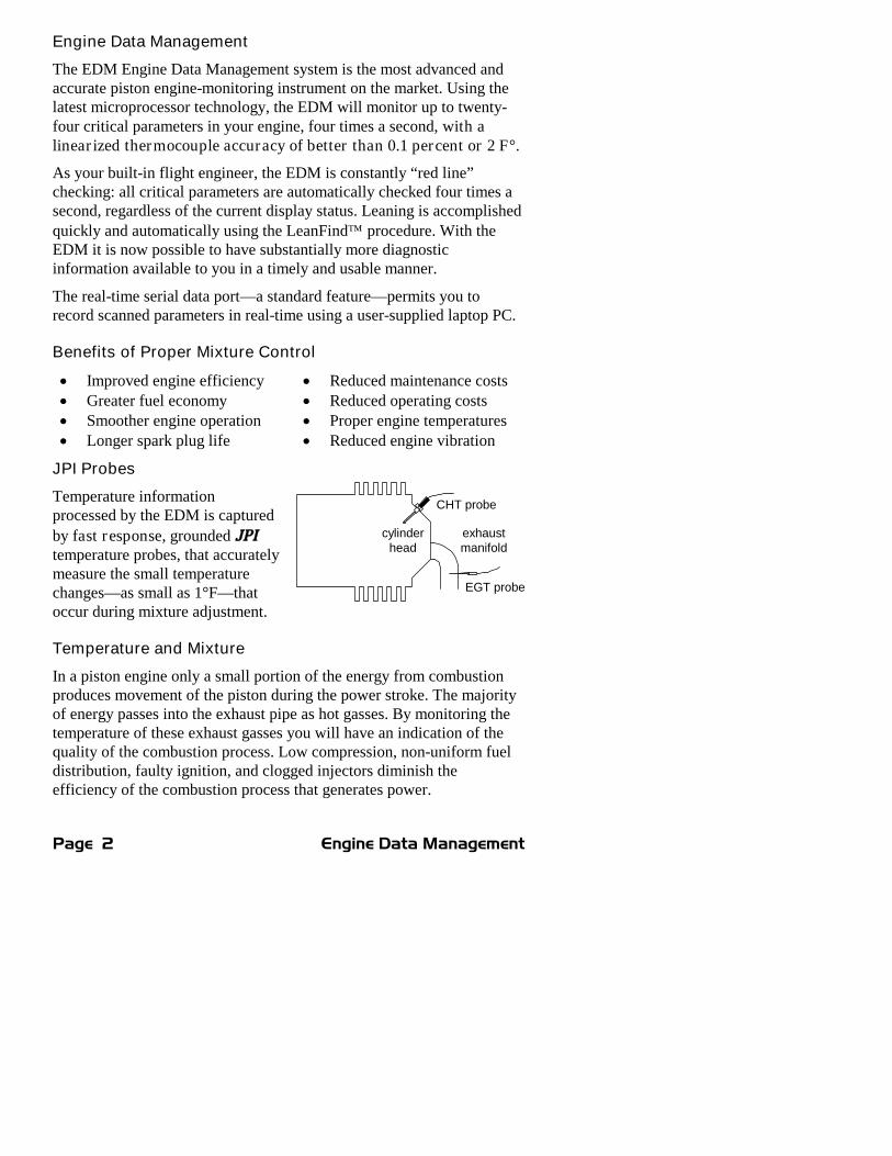
JPI Probes
Temperature informationprocessed by the EDM is captured
by fast response, grounded JPItemperature probes, that accuratelymeasure the small temperaturechanges—as small as 1°F—thatoccur during mixture adjustment.
Temperature and Mixture
In a piston engine only a small portion of the energy from combustionproduces movement of the piston during the power stroke. The majorityof energy passes into the exhaust pipe as hot gasses. By monitoring thetemperature of these exhaust gasses you will have an indication of thequality of the combustion process. Low compression, non-uniform fueldistribution, faulty ignition, and clogged injectors diminish theefficiency of the combustion process that generates power.
CHT probe
EGT probe
cylinderhead
exhaustmanifold

For Your Safe Flight Page 3
From the cockpit you can adjust the fuel/air ratio by a process calledleaning. Retarding the mixture control changes the fuel/air ratio andhence the resulting Exhaust Gas Temperature (EGT).
The following figure depicts the mixture and temperature relationship.
EG
T°F
be
low
pe
ak
Pe
rce
nto
fb
estp
ow
er
CH
T°F
ch
an
ge
fro
mb
estp
ow
er
Bestpowerrange
0
-100
-50
-20
20
-60
-40
0
-80
100
85
90
95
80
Percent power
Specific fuel consumption
Toolean
LeanRichFull Rich(Take-off)
EGT
CHT
First cylinder topeak. Use forRich of Peak
leaning
Last cylinder topeak. Use forLean of Peakleaning with GAMIinjectors
Peak Power
Besteconomy
range
GAMIspread
As the mixture is leaned, EGT rises to a peak temperature, and thendrops as the mixture is further leaned. Peak power occurs at a mixtureusing more fuel than at peak EGT. Best economy occurs at peak EGT.Accurate leaning yields optimal engine temperatures. By being able toprecisely adjust the mixture, your engine can produce either the best fueleconomy or maximum power, whichever you choose.

Page 4 Engine Data Management
A single EGT gauge merely gives you an average of each cylinder’stemperature: some cylinders can be too rich, while others too lean.Variations produced by differences in fuel distribution, ignition, andcompression will cause each cylinder to follow its own mixture andtemperature relationship such that one cylinder will reach peak beforeanother.
Section 2 - Displays and Controls
The EDM monitors engine temperatures and voltages, assists inadjusting the fuel/air mixture, and helps diagnose engine malfunctions.There are three components of the user interface:
Analog display including cylinder number and index dot Digital display for numeric readouts and messages Two front panel operating buttons.
Displays
I340 376STEP LF
1 2 3 4 5 6 T
7 3 HPNRM F
EDM 800JPI
_EGT
%Limit
_250
350
450
CHT
TSO
°F or °C
Dash line orNRM indicatesNormalize orPercent view
Cylindernumbers 1
through 6. T isTIT otherwise
oil temp
Exhaust GasTemperature(EGT) is the top ofthe column
PercentHP
or RPM(EDM-
800 only)
Dot indicates whichcylinder temperatures
are shown in thedigital display
Cylinder HeadTemperature
(CHT) is shownas a missing
segment
Maximumline is theEGT, TIT
and OILredline
CHTabsolute
scale
Systems withboth TIT andOIL, OIL isshown asmissing segment
Analog Display
The upper half of the face of the EDM is the analog display with %HP.
The following is a description of the analog display, from top to bottom.Numbers in circles refer to features in the above diagram.

For Your Safe Flight Page 5
Normalize and Percentage View Indicators
Percentage view: when there is a dash — near the P at the top ofthe display (EDM-700) or NRM is not lighted (EDM-800), thecolumns indicate percent of EGT red line. Each column iscomposed of a stack of segments. A maximum height columndepicts 100 % of red line and a one segment-high columndepicts 50 % of red line. For example, if the red line is 1650°F, amaximum height column represents 1650°F and a one segment-high column represents half that value, or 825°F. ThePercentage view permits comparison of EGTs across allcylinders. Hotter cylinders display higher columns than coolercylinders.
Normalize view: when there is a dash _ near the N at the top ofthe display (EDM-700) or the letters NRM are lighted on the leftside (EDM-800), the EGT columns are displayed normalized.When you change to the Normalize view, all column peaks areset to the same half-height level for trend analysis. Any changesare shown as an increase or decrease in column height. A one-segment change in column height represents a 10°F change.The Normalize view permits rapid visualization of EGT trends,rather than a percentage of red line. You should use normalize inlevel cruise and run-up.
To toggle between Percentage and the Normalize views, hold the LFbutton for five seconds until the display changes. The analog displaybecomes half height and the display changes to the Normalize view.Selecting the Normalize view does not affect the digital display nor alterthe parameter sequence. The CHT display—described later—is notaffected by the Normalize or Percentage view.
You may select the Normalize view in either the Manual or Automaticmode. Normalize view is most helpful for engine trend monitoring ofeach cylinder’s operation. For example using the Normalize view duringengine run-up, a fouled spark plug will appear as a higher column.
A common misapplication is to be in the Normalize view and thenchange your power setting, causing all columns to go off scale, high orlow. Set to the Percentage view before adding or reducing power.Always set Percentage View when beginning your descent.
Temperature Units (°F or °C)
°F temperatures in the digital display are in Fahrenheit degrees. °C temperatures in the digital display are in Celsius degrees.

Page 6 Engine Data Management
To change the display of engine temperatures see “Changing theAlarm Limits” on page 42.
Cylinder Numbers and Dot Index
A row of numbers 1 through 6 and the letter T are the column labels forthe analog display. The 1 through 6 are the cylinder numbers. If the TIToption is installed, the T denotes the last column is displaying TurbineInput Temperature (TIT) as a column. If the T is absent and the Oiltemperature option is installed, the last column displays Oil temperature.If both TIT and Oil temperature options are installed, the last columndisplays TIT and the missing segment displays Oil temperature. Thehighest Oil temperature segment will flash only when the digital displayshows OIL. The highest TIT segment will flash on when the digitaldisplay shows TIT. A round dot under the numbers 1 through 6 indicatesthat particular column is shown numerically in the EGT and CHT digitaldisplay.
Bar Graph EGT and CHT
Each column in the bar graph is composed of a stack of segments. Thetotal height of each column represents the EGT and the missing segmentin the column represents the CHT.
In the Percentage view, the EGT, TIT, and Oil temperatureresolutions depend on the programmed red line limits.
CHT is displayed by a missing segment andshould be interpreted as follows: a missingsegment corresponds to the CHT in 25 F°increments, starting at 250°F at the bottom. Inthe example shown here, the CHT is 300°F. If the EGT baris lower than the missing CHT segment, then the CHT willbe indicated by a single isolated lighted segment.
The CHT display is the not affected by mode or view.
Percent HP (EDM-800 only)
Displays percent of rated HP or RPM depending on pilot programming.
Digital Display
Beneath the bar graph is the 9-segment alphanumeric display.
EGT and CHT
When the dot index is beneath a cylinder number, 1 through 6, the digitaldisplay shows the EGT on the left (four digits) and the CHT on the right
250
350
450
CHT

For Your Safe Flight Page 7
(three digits). Other parameters are displayed in the digital display asdescribed in the subsection “Parameter Scan— EDM-700 without Fuel
Flow Option” on page 9. The EDM-711 will briefly display EGT – CHTbefore displaying the numerical values.
I340 376STEP LF
1 2 3 4 5 6 T
73 HPNRM F
EDM 800JPI
_EGT
%Limit
_250
350
450
CHT
TSO
4 digitdisplay of
EGT
3 digitdisplay ofCHT
Display Dimming
The entire display panel features automatic dimming. Allow ten secondsfor the display to adjust to ambient lighting conditions.
Modes
There are three standard operating modes of the EDM: Automatic,Manual, and two LeanFind submodes. These modes will be described inmore detail beginning on page 11. Most of the time you will operate theEDM in the Automatic mode. When you first turn on the power theEDM starts in the Manual mode, but will enter the Automatic mode aftertwo minutes. The three modes affect primarily the digital display.
Automatic Mode
Just tap the LF button, then tap the STEP button. No userintervention is required to use this mode. Each cylinder and eachparameter value is automatically sequenced and shown in the digitaldisplay for a few seconds. The EDM-711 will automatically scan onlythe primary temperatures: highest CHT, TIT, OIL.
Manual Mode
Just tap the STEP button. Automatic stops. Each indexed parameter isfrozen in the digital display until you manually index to the nextparameter by tapping the STEP button. The EDM-711 will manuallyscan all parameters.

Page 8 Engine Data Management
LeanFind Mode
Simply pre-lean, tap the LF button and begin leaning. The EDM willassist you in finding the first cylinder to peak.
Buttons
I340 376STEP EDM-700 LF
JPISTEP button LF button
Buttons, Front Panel
Two operating buttons control all functions of the EDM.
The term tap will be used to denote pressing a button momentarily. Theterm hold will be used to denote pressing and holding a button for fiveseconds or longer.
STEP Button
Located on the lower left side near the instrument face.
In the Automatic mode, tapping the STEP button will stopand change to the Manual mode. Then each tap of the STEPbutton will display the next parameter in the sequence.
In the LeanFind mode tapping the STEP button willterminate the LeanFind mode and change to the Automaticmode.
Secondary functions of the STEP button include:
In the Manual mode holding the STEP button will display the previousparameters in the sequence (rapidly backwards).
In the programming procedures, tapping the STEP button will advance tothe next item in the list.
When an alarm is displayed, tapping the STEP button will temporarilydelete that alarm from appearing for the next ten minutes.
When an alarm is displayed, holding the STEP button until the word OFFappears will delete that alarm from appearing for the remainder of theflight.
LF Button
Located on the lower right side near the instrument face.

For Your Safe Flight Page 9
In Automatic or Manual modes, tapping the LF button willchange to the LeanFind mode.
In Automatic or Manual modes holding the LF button forthree seconds will toggle between Percentage and Normalizeviews.
N: Normalize viewP: Percentage view hold LF buttonfor 3 seconds
In the LF mode holding the LF button after peak EGT isfound will display peak EGT.
Secondary functions of the LF button include:
In the pilot programming procedure, holding or tapping the LF button isused to increment or decrement parameter values and toggle between Yesand No answers to questions.
STEP and LF Buttons
Holding both the STEP and LF buttons simultaneously forfive seconds changes to the pilot programming procedure.
Holding both the STEP and LF buttons simultaneously forfive seconds after entering LeanFind mode but beforebeginning to lean will toggle between leaning “rich of peak”and “lean of peak.”
Tapping both the STEP and LF buttons simultaneously inManual mode toggles to include or exclude the displayedparameter from the Automatic mode. It has no affect on thedisplayed parameters in the Manual mode.
In the LF mode tapping both the STEP and LF buttonssimultaneously will mark a data record in long term
memory and display will flash SNAP.
Parameter Scan— EDM-700 without Fuel Flow Options
The EDM steps through the engine parameters in a specific sequence.Listed below is the sequence, parameter description and example of thedigital display.

Page 10 Engine Data Management
Parameter Example CommentsVoltage, System Bus I4.2 BAT Battery voltage
Outside Air Temperature 8I OAT °F or °C
Induction AirTemperature
I25 IAT Out of the intercooler
Compressor DischargeTemperature
300 CDT Into the intercooler
Carburetor Temperature -22 CRB Not available when CDT isinstalled
Difference betweenhottest and coolest EGT
80 DIF Dot indicates most widelydeviating cylinder
EGT, CHT I340 376 EGT, left, CHT, right. Dotindicates cylinder
TIT, Turbine InletTemperature
TIT
TI2
Turbine #1, left shows ascolumn.Turbine #2, right
Oil Temperature I78 OIL Missing bar in TIT column or iscolumn
Shock Cooling -30 CLD Dot indicates fastest coolingcylinder
The display will pause at each parameter for four seconds in theAutomatic mode. (The four second pause time can be changed.) In theManual mode, tap the STEP button to advance to next parameter. Onlythe parameters for the options that are installed will be displayed;uninstalled parameters will not appear.
Automatic Parameter Scan—EDM-711
The EDM-711 in automatic scan mode will display only the followingthree primary temperatures: highest CHT, OIL and if the option isinstalled, TIT.
For Your Safe Flight Page 11
Section 3 - Operating Procedures
Diagnostic Testing on Startup and During Flight
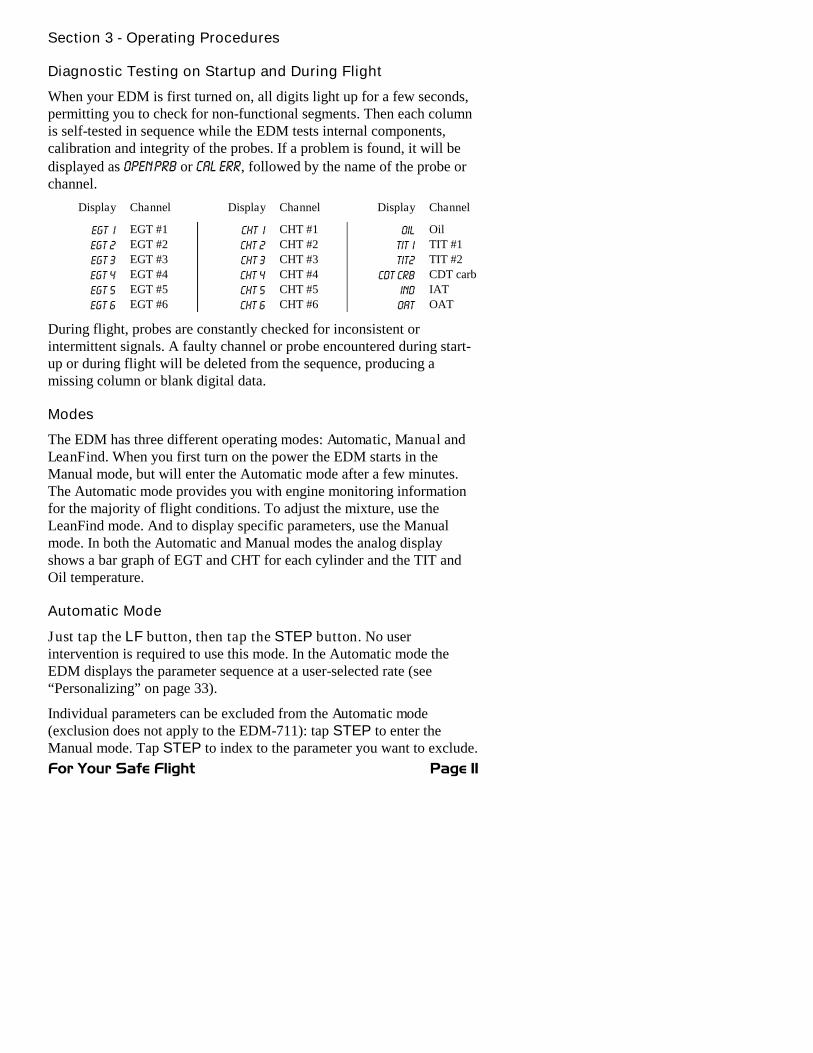
When your EDM is first turned on, all digits light up for a few seconds,permitting you to check for non-functional segments. Then each columnis self-tested in sequence while the EDM tests internal components,calibration and integrity of the probes. If a problem is found, it will be
displayed as OPEN PRB or CAL ERR, followed by the name of the probe orchannel.
Display Channel Display Channel Display Channel
EGT I EGT #1 CHT I CHT #1 OIL Oil
EGT 2 EGT #2 CHT 2 CHT #2 TIT I TIT #1
EGT 3 EGT #3 CHT 3 CHT #3 TIT2 TIT #2
EGT 4 EGT #4 CHT 4 CHT #4 CDT CRB CDT carb
EGT 5 EGT #5 CHT 5 CHT #5 IND IAT
EGT 6 EGT #6 CHT 6 CHT #6 OAT OAT
During flight, probes are constantly checked for inconsistent orintermittent signals. A faulty channel or probe encountered during start-up or during flight will be deleted from the sequence, producing amissing column or blank digital data.
Modes
The EDM has three different operating modes: Automatic, Manual andLeanFind. When you first turn on the power the EDM starts in theManual mode, but will enter the Automatic mode after a few minutes.The Automatic mode provides you with engine monitoring informationfor the majority of flight conditions. To adjust the mixture, use theLeanFind mode. And to display specific parameters, use the Manualmode. In both the Automatic and Manual modes the analog displayshows a bar graph of EGT and CHT for each cylinder and the TIT andOil temperature.
Automatic Mode
Just tap the LF button, then tap the STEP button. No userintervention is required to use this mode. In the Automatic mode theEDM displays the parameter sequence at a user-selected rate (see“Personalizing” on page 33).
Individual parameters can be excluded from the Automatic mode(exclusion does not apply to the EDM-711): tap STEP to enter theManual mode. Tap STEP to index to the parameter you want to exclude.

Page 12 Engine Data Management
Then tap both the STEP and LF buttons simultaneously. Excludedparameters display a decimal point before the parameter name. Forexample:
Included: I84 OIL Excluded: I84 .OIL
Tapping the STEP and LF buttons simultaneously will toggle back andforth between include and exclude.
Every time you turn on the EDM, all parameters are reset to beincluded.
All installed parameters are always displayed in the Manual mode.Exclusion only applies to the Automatic mode.
All parameters are checked for alarm conditions every secondregardless of their included or excluded status.
Manual Mode
Just tap the STEP button. Use the Manual mode when you want tomonitor one specific parameter such as shock cooling during descent, ora particular cylinder temperature during climbs. To change to theManual mode, tap the STEP button once. Subsequent taps will index thedigital display through the parameter sequence (see “Parameter Scan—EDM-700 without Fuel Flow Option” on page 9). To exit the Manualmode and return to the Automatic mode, either tap the LF button andthen tap the STEP button—see “How to Change Modes” in the front ofthis manual. You may disable the Automatic mode by setting “0” forscan rate (disabling Automatic mode does not apply to EDM-711).
LeanFind Mode—Leaning Rich of Peak
JPI’s EDM-700 and EDM-800 provide two methods of leaning: lean
rich of peak (LEAN R) or lean of peak (LEAN L). The standard method isto lean about 20° rich of peak. With the advent of GAMI injectors it isnow possible to set the mixture lean of peak—saving fuel and runningthe engine cooler. Teledyne Continental recommends lean of peak forthe Malibu. This manual primarily describes the rich of peak method,and provides the procedure for the lean of peak method. The defaultmethod is set to rich of peak.
Simply pre-lean, tap the LF button and begin leaning. Upon reachingcruise configuration, you will use the LeanFind mode to identify the firstcylinder to reach peak EGT.

For Your Safe Flight Page 13
LeanFind Procedure—Step-by-Step
Procedure Example Comments1 Establish cruise at approx.
65 to 75% power.
2 Pre-lean the mixture to 50°Festimated rich of peak EGTon any cylinder: _____°
I490 370 *For your first flight with theEDM, use the method shownbelow.
3 Wait one minute Let engine stabilize.
4 Tap the LF button LEAN R Start LeanFind. (Optionally tochange to “lean of peak”method, hold both STEP andLF simultaneously.)
5 Lean the mixture—approx.10°/second withoutpausing—while observing thedisplay. When there is a 15°Frise in EGT, LeanFind modebecomes active.
I520 LFWithout FF
I520 I3.8With FF
Flashing cylinder DOTindicates hottest cylinder andthat LeanFind mode is active.
6 Stop leaning whena column begins flashing.You will see LEANEST for twoseconds, followed by:
I545 SETor withFuel Flow
I545 I 2.4
Flashing cylinder dot &column indicates leanestcylinder. (SET means Set themixture.) Due to thermalinertia this will usually beabout -15°F lean of peak.
7 If you hold LF, peak EGT willbe displayed while the LFbutton is held down.
I560 PK Captured peak EGT value isdisplayed.
8 Slowly enrich the mixture. thetemperature will increase,returning to peak.Stop enriching at the desiredEGT.
Best economy
Best power
I560 SET
I560 SETI460 SET
Peak EGT for besteconomy
100° rich of peak for bestpower
Bestpower
Temperature whencolumn flashes
best economy
leanerricher
9 If you have chosen the Leanof Peak method, at step 5continue leaning until the lastcylinder has peaked.
-I5 SETOR-I5 I2.3
Only for GAMI injectedengines. When each cylinderreaches peak, the cylindernumber will begin flashing.
*Determining the pre-lean value: while in cruise at under 65 percentpower, choose any cylinder and lean that cylinder to peak EGT in theManual mode or to engine roughness, whichever occurs first. Note thepeak, subtract 50° and write the resulting number in the space providedin step 2.
LeanFind Procedure—General Explanation

Page 14 Engine Data Management
Lycoming and Continental engines have established specificrestrictions on leaning that must be followed, such aspercentage of power, climb leaning, and TIT limits. Lycomingrecommends operation at peak EGT for power settings of75% or lower, while Continental recommends operation atpeak EGT for power settings of 65% or lower. This guide isnot meant to supersede any specific recommendations of theengine manufacturer or airframe manufacturer.
It is your responsibility to know your aircraft’s limitations.
Pre-lean the mixture to about 50° below peak. After pre-leaning, wait forone minute for the temperatures to stabilize. Next, begin the leaningprocess by tapping the LF button. This tells the EDM to begin lookingfor a 15° rise in EGT for any cylinder. Begin leaning the mixture withoutpausing. When a 15° rise occurs, eliminating false peaks, the LeanFindmode becomes activated shown when the cylinder dot above the columnof the hottest cylinder begins flashing. The LeanFind mode is notactive until a cylinder dot is blinking.
With the Fuel Flow Option, instead of seeing the word LF in thedisplay, you will see numerical fuel flow rate during the leaning
process on the right side of the digital display, for example I2.4.This allows you to observe the EGT rise and at the same timewatch the fuel flow rate decrease.
To show the progress of the leaning process, the EDM selects the hottestcylinder for reference in the digital display. In the example below, the
I360 is the current temperature of the hottest cylinder.
I360 LFSTEP EDM-700 LF
° F1 2 3 4 5 6 T
N P
JPI
_
_EGT
%Limit
_300
400
500
CHT
TSO
number ofhottest cylinderflashes whenEGT rises 15°
dotindicateshottestcylinder
temperatureand "LF"displayed
When LF is activated:

For Your Safe Flight Page 15
Continue leaning slowly without pausing. With a vernier mixturecontrol, turn the knob about a quarter turn every second. With a non-vernier or quadrant mixture control, lean slowly and smoothly about1/16 inch every five seconds. Eventually, one cylinder will reach peakbefore any of the other cylinders. The EDM will determine thisautomatically. Notice that this cylinder does not necessarily have thehottest EGT.
The EDM will indicate success in finding a peak by displaying the
words LEANEST for two seconds, followed by flashing the column anddisplaying the value of the EGT of the cylinder that peaked first. The
word SET will also be displayed. (With the Fuel Flow Option the currentfuel flow rate will be displayed on the right side of the digital display
instead of the word SET.) The flashing cylinder will be locked—or set—into the digital display during the remainder of the LeanFind procedureto allow you to set the final mixture. The peak EGT value is rememberedby the EDM and will be displayed as long as you hold the LF button.
You may now enrichen the mixture to operate at peak or continueenriching to 100° rich of peak, or a value of your choice, consistent withthe procedures defined in your aircraft engine manual.
If you lean too much, the EGT will drop and the engine will be operatinglean of peak.
I340 SETSTEP EDM-700 LF
° F1 2 3 4 5 6 T
N P
_
JPI
_
LEANESTLEANESTdisplayed fortwo secondswhen peak isfound
Leaning Rich of Peak
_EGT
%Limit
_250
350
450
CHT
TSO
Cylindernumber of theLEANESTcylinder flashes
Dot indicatesLEANESTcylinder
Column of theLEANESTcylinder flashes
EGT of theLEANEST cylinderdisplayed with thethe word SET
Lean of Peak Leaning with GAMI injectors

Page 16 Engine Data Management
To use the “lean of peak” method, tap LF and then immediately hold
both STEP and LF until you see LEAN L. Once you begin leaning(flashing dot) you cannot change leaning methods. You may toggle back
to LEAN R by holding both buttons again.
Leaning Lean of Peak
-5 7.3
73 HP
1 2 3 4 5 6 T
_
STEP LFEDM 800JPI
_EGT
%Limit
_300
400
500
CHT
TSO
Cylinder numberflashes when thecylinder peaks
Temperaturebelow peak oflast cylinder topeak
Shortestcolumn isthe lastcylinder topeak
Current fuelflow rate
First cylinder topeak haslargest column
Hold LF to seepeaktemperature oflast cylinder topeak (e.g. I340)
Hold LF to seeGAMI spread(delta fuel flow)
In the “lean of peak” method the columns will invert with the first topeak progressing down from the top of the display. The inverted columnscale is 5° per segment below peak. As you continue to lean past peakthe dot of the each successive cylinder will flash as it peaks. The peakswill be shown as an inverted bar graph; when the last cylinder peaksits column will flash. The analog display is an inverted bar graphshowing where each cylinder peaked. When the LF button is held thedisplay will show the delta fuel flow between the first and last to peak(GAMI Spread), as well as the richest peak EGT.
If you tap STEP, scanning will resume. Or instead, if you Tap LF youwill return to the inverted bar graph, which can be used for fine tuning.To begin the LeanFind procedure anew, tap LF a second time.
Turbocharged Engines
The leaning process for turbocharged engines is by reference to the firstcylinder or TIT to reach peak. However, the TIT factory red line maylimit the leaning process. TIT red line is generally 1650°F, and up to1750°F in some installations. In the LeanFind mode the T column—TIT—is included in the procedure. If during leaning the TIT exceeds redline by less than 100° for less than one minute, the LeanFind procedurewill continue to operate, allowing you to complete the leaning process.
Otherwise the digital display will show, for example, I650 TIT and TIT will

For Your Safe Flight Page 17
flash. You will notice that in some cases the TIT reads 100°F hotterthan the hottest EGT. This is caused by unburned fuel in the exhaustand igniting.
The reduced size of the JPI Hastaloy-X-tip probes produces fasterresponse and more accurate than the massive factory installed probe.
Therefore JPI probes may read as much as 100°F higher than thefactory installed probe. However, note that the engine was certified withthe factory-installed probe and gauge, and this gauge reading is thelimiting factor when adjusting your engine.

Page 18 Engine Data Management
Operation for each Phase of Flight
Engine Run-Up
Suggested setup:
Runup RPM
Normalize view
Manual mode
Verify: uniform rise of about 50°F in all EGTs in single
magneto operation uniform rise of EGTs with application of the
mixture control.Be alert for: unusually low voltage (less than nominal battery
voltage) cold OIL abnormally high CHT a higher EGT on one cylinder in dual magneto
operation—indicates fouled spark plug.Include your EDM on your run-up checklist.
Take-Off, Climb, and Full Throttle Operations
Suggested setup:
Percentage view
Automatic mode
Verify: EGTs and CHTs consistent with past climbs.
EGTs should be the 1100 to 1250°F range (100°to 300°F cooler than cruise) due to fuel cooling.
Be alert for: high EGT in one cylinder, 300°F above the
others may indicate plugged injector or leakingmanifold gasket.
If all EGT bars go off scale to the top of thecolumn, be sure you are not in Normalize view.
At high density altitude an overly rich mixture can significantly reduceengine power.

For Your Safe Flight Page 19
Cruise
After the engine is warmed up, use LeanFind to lean the mixture.
Suggested setup:
Percentage view
Automatic mode
Be alert for: uneven EGTs or CHTs (carbureted engines).
Make fine adjustments to throttle, then RPM,then mixture to level the display columns.
abnormal patterns of EGTs and CHT. (see“Diagnosing Engine Problems” on page 21).
Descent
Suggested setup:
Percentage view
Manual mode
Be alert for: CLD: shock cooling alarm is set to –60°F.
Average cool rates of –40°F/minute to–60°F/minute are normal, depending on theengine size.
Shock Cooling
Cooling the cylinders too fast can result in cracking and eventual failure.Lycoming Service Instruction 1094D (March 25, 1994) on Fuel MixtureLeaning Procedures states:
“At all times, caution must be taken not to shock cool thecylinders. The maximum recommended temperature changeshould not exceed 50°F per minute.”
JPI checks shock cooling on all cylinders displaying the highestreading cylinder.

Page 20 Engine Data Management
Common Misapplications
Some of the more common misapplications made by first-time EDMusers are presented here in an attempt to help you avoid similarproblems.
Problem Situation Correction
LeanFind finds a“peak” too soon.
Failure to pre-leanbefore performingLeanFind or stoppingwhile leaning.
Follow the pre-leanprocedure in thesection “LeanFindMode” on page 12.
Leaning too slowly. Lean more quickly.
Peak not found Lean Find not activatedor stopping whileleaning
Lean at the speed ofapproximately 10°Fper second.
Off-scale EGTbars, too high orlow
You forgot that you setthe EDM in theNormalize view andlater observe off-scaleEGT bar readings.
The higher sensitivity(10° per segment) ofthe Normalize viewcan quickly go too highor low off-scale withonly small changes inEGT.
First cylinder topeak is not thehottest
This is normal. Thefirst to cylinder peak isnot necessarily thehottest.
EGTs rise duringsingle magnetocheck
This is normal, due toincomplete combustionpersisting longer.
EGTs not uniformduring low poweroperation
This is normal. Fueland air distribution isnot optimal at lowpower settings.
No display of%HP
Fuel flow not reading Fuel Flow option isrequired for HP

For Your Safe Flight Page 21
Section 4 - Diagnosing Engine Problems
Typical Normal Parameters
The follow chart lists typical normal parameter values that you willobserve for most general aircraft engines.
Parameter Normal range Comments
EGTs in Cruise 1350°F1550°F
under 200 HP high performance EGT should drop 200°F
when full throttle isapplied
EGT span (DIF) 70 to 90°F120 to 150°F
fuel injected carbureted
TIT 1600°F average 100° higher than EGT
CHTs 350°F (OAT 60°F)410°F
normally aspirated Turbocharged
CHT span 50 to 70°F 100° with gasket probes
OIL 200°F oil cooler thermostatopens at 180°F
Shock cooling* -40°/minute-55°/minute
-200°/minute
tightly cowled Bonanza helicopter
* Maintain a cooling rate of less than -60°/minute. You will find that thecylinder with the greatest shock cooling will shift from front cylinders(during climb out) to the rear cylinders (during descent ).
If one CHT is reading 20° to 50° above or below the others, this may bedue to that cylinder having a spark plug gasket probe instead of abayonet probe. This is necessary because the aircraft’s factory originalCHT probe is occupying the socket in the cylinder head rather than theEDM. This is normal. If the discrepancy is greater, be sure the sparkplug gasket probe is mounted on the top spark plug. An adapter probe isavailable to occupy the same socket as the factory original probe.Contact your dealer.
Page 22 Engine Data Management
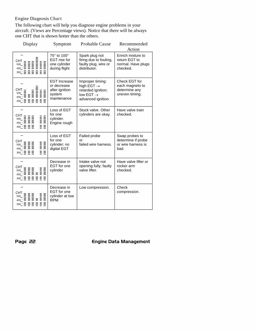
Engine Diagnosis Chart
The following chart will help you diagnose engine problems in youraircraft. (Views are Percentage views). Notice that there will be alwaysone CHT that is shown hotter than the others.
Display Symptom Probable Cause RecommendedAction
CHT
300
400
500
75° to 100°EGT rise forone cylinderduring flight
Spark plug notfiring due to fouling,faulty plug, wire ordistributor.
Enrich mixture toreturn EGT tonormal. Have plugschecked.
CHT
300
400
500
EGT Increaseor decreaseafter ignitionsystemmaintenance
Improper timing:high EGT retarded ignition;low EGT advanced ignition.
Check EGT foreach magneto todetermine anyuneven timing.
CHT
300
400
500
Loss of EGTfor onecylinder.Engine rough
Stuck valve. Othercylinders are okay.
Have valve trainchecked.
CHT
300
400
500
Loss of EGTfor onecylinder; nodigital EGT
Failed probeorfailed wire harness.
Swap probes todetermine if probeor wire harness isbad.
CHT
300
400
500
Decrease inEGT for onecylinder
Intake valve notopening fully; faultyvalve lifter.
Have valve lifter orrocker armchecked.
CHT
300
400
500
Decrease inEGT for onecylinder at lowRPM
Low compression. Checkcompression.

For Your Safe Flight Page 23
Display Symptom Probable Cause RecommendedAction
CHT
300
400
500
EGT and CHTnot uniform
Dirty fuel injectorsor fouled plugs.
Check injectors andplugs. Non-uniformity is normalfor carburetedengines
CHT
300
400
500
Decrease inEGT for allcylinders
Decrease in airflowinto the inductionsystem. Carb orinduction ice.
Engine units set toCelsius
Check for changein manifoldpressure.
Check that thealarm limits are setto Celsius degrees
CHT
300
400
500
Slow rise inEGT. LowCHT
Burned exhaustvalve. CHT is lowdue to low poweroutput.
Have compressionchecked.
CHT
300
400
500
High CHT oncylinders onone side ofengine
Obstruction undercowling.
Check for improperinstalled baffling,cowl flapmisalignment orbird nests.
CHT
300
400
500
Rapid rise inCHT of onecylinder
Detonation. Reduce power.
CHT
300
400
500
Sudden offscale rise forany or allcylinders
Pre-ignition
or Normalize view.
or failed probe
Full rich and reducepower.
Change toPercentage view.
Check probe

Page 24 Engine Data Management
Display Symptom Probable Cause RecommendedAction
(no picture) Loss of peakEGT
Poor ignition orvapor in fuelinjection system.
Have magnetotested.
(no picture) Decrease inpeak or flatEGT responseto leaningprocess
Detonation. Usuallythe result of 80Octane fuel in 100Octane engine.
Enrich mixture,reduce power andrelean mixture.Repeat to findpower settingwhere normal peakis obtained or runrich.
CHT
300
400
500
Below 10,000ft. full throttlecauses EGTsto rise
Weak or defectivemechanical fuelpump.
Apply boosterpump. If EGTsdrop, replace fuelpump.
CHT
300
400
500
CHT morethan 500°,EGT normal.Adjacent EGTmay be low
Leaking exhaustgasket blowing onCHT probe.
Look for whitepowder aroundcylinder todetermine leakarea.
Large DIF atlow RPM
Blow by in cylinderrings
Check compression
Alarms
The EDM has programmable alarms. When a parameter falls outside ofits normal limits, the digital display will flash with the value andabbreviation of the alarming item. If the condition triggering the alarmreturns to within normal limits, the display will stop flashing the alarm.If your installation includes a separate panel mounted alarm warningenunciator light or audible warning, it too will be activated.
There are no alarms for the individual EGTs because the temperaturevalues can assume different ranges depending on the flightconfiguration—run up, climb, cruise. However there is an alarm on theDIF parameter, the difference between the hottest and coolest EGTs.DIF—or span—is the important parameter for monitoring the EGTs. See“Factory Set Default Limits” on page 42 for a list of the alarms and theirfactory default settings.

For Your Safe Flight Page 25
When an alarm is displayed, tapping the STEP button will temporarilydisable the alarm digital indication for the next ten minutes.
When an alarm is displayed, holding the STEP button until the word OFFappears will disable that alarm digital indication for the remainder of theflight. See “Alarm Limits” on page 41.
EDM-711 primary alarm display lamps cannot be disabled.
Alarm Priority
If multiple alarms occur simultaneously, the higher priority alarm willtemporarily “mask” the lower priority alarm(s). When an alarm occurs,note the cause of the alarm and tap the STEP button to clear the alarmindication so that you will be notified of any other alarm that might haveoccurred. The alarm priorities are as follows:
Highest priority CHT High CHT
OIL High OIL temperature
TIT High TIT
OIL Low OIL temperature
CLD Excessive CHT cooling rate
DIF Excessive EGT span
BAT High battery voltage
BAT Low battery voltage
MAP Overboost Manifold pressure
LO FUEL Low fuel quantity remainingLowest priority LO TIME Low fuel endurance remaining
Pre-Ignition and Detonation
Combustion that is too rapid leads to detonation and possibly pre-ignition. Detonation is abnormally rapid combustion where the fuel-airmixture explodes instead of burning uniformly. It causes the EGT todecrease and the CHT to increase, and can appear during the leaningprocess. It occurs under high compression from fuel with too low anoctane rating, or from avgas contaminated by jet fuel. Fuel additives,such as lead, boost the octane rating and slow down the combustionprocess, producing an even pressure to the piston.
Pre-ignition is caused by hot spots in the cylinder. Ignition occurs priorto the spark plug firing. The EDM depicts pre-ignition as a sudden redline of the EGT on the analog display. This may occur in one or morecylinders. The affected cylinder column(s) will flash while the digitaldisplay will show an EGT higher than 2000°F. At this temperature

Page 26 Engine Data Management
pre-ignition will destroy your engine in less than a minute unless youtake immediate corrective action.
Section 5 - Fuel Flow Option Operation
Fuel Flow Display Select Switch
The select switch is a three-position toggle switch mounted on yourinstrument panel near the display of the EDM. It affects only the displayscan.
In the EGT (Temperature) position only the installedtemperature (and battery voltage) parameters are displayed.
In the ALL (All) position, the EDM both installedtemperature and fuel flow parameters are displayed.
In the FF (Fuel Flow) position only fuel flow parameters aredisplayed.
Any alarm warning will appear regardless of the select switch setting.These parameters are displayed in the digital display in either theAutomatic or Manual modes or during the pilot programming procedure.The select switch does not effect the analog display. EDM-711: thetoggle switch is disabled during Automatic scan mode.
Start Up Fuel
After initial self-test, you will be asked to inform the EDM of start up
fuel. The EDM will display FUEL for one second, and then flash FILL? Nuntil any button is pressed. If your aircraft has tank fill tabs and noauxiliary tanks, you can use the auxiliary tank feature to select eitherfilling to the tank tabs or topping the tank. See “Main Tank Capacity”beginning on page 44 to program the EDM for this feature. The EDMdoes not differentiate fuel flow between the main and auxiliary tanks; itconsiders only total fuel in the aircraft. During flight you may alsoinform the EDM of startup fuel using the pilot program modedisplay if you forgot to do so at start up.
main tank
auxiliary tank
main tank with tab
tabAuxiliary capacity
Main capacity

For Your Safe Flight Page 27
Refer to the flow chart. Then tap the STEP button to complete the entryand advance to the Manual mode.
Adding Fuel and Auxiliary Tanks
If you eithera) added less than full fuel to only
the main tanks, orb) topped the main tanks but have
some fuel remaining in theauxiliary tanks,
then select FILL + and the next display
will ask you how much you added: .0 GAL(or selected units). Hold the LF button tocount up, tap the LF button to countdown. The count up will stop at fulltanks, since you cannot add more fuelthan would top the tanks.
If you added fuel to only the main tanks,then input how much you added.
If you topped the main tanks, but havesome fuel remaining in the auxiliarytanks, input how much is now in theauxiliary tanks.
You can “add” a negative amount of fuelif you remove fuel from the aircraft or
wish to correct the total quantity of fuel on board.
Accumulate Total—Trip Total
You may either display total fuel used since the last time you informedthe EDM that the aircraft was refueled, or for an extended trip with
multiple fuel stops. This selection affects only the USD parameter. Howto select whether to accumulate or reset is described in “PilotProgramming” beginning on page 33.
Resetting “USED”
Every time you inform the EDM that the aircraft is refueled, the amountof fuel used is set to zero, unless the instrument is programmed toaccumulate. The display of fuel used pertains only to the fuel used sincethe last time you informed the EDM that the aircraft was refueled.
Power up
FUEL ?N
Pgm Refuel
Program
FILL ?N
FILL ?75 *
Yes Change
Fill ?+
OK Start
Exit Fill
.0 GAL
Done +/-
FILL ?120 *
Yes Add
STEP LF
STEP LF
STEP LF
STEP LF
STEP LF
STEP LF

Page 28 Engine Data Management
To reset to zero the amount of fuel used at any point in time, manually
step to display USD and hold both buttons for five seconds until the
display shows .0 USD.
Fuel Management
Without a means of measuring fuel flow, you must rely on the aircraftfuel gauges or total time of flight. Aircraft fuel gauges are notoriouslyinaccurate (they are only required by the FAA to read accurately whendisplaying empty). And measuring time of flight is only anapproximation, and assumes a constant fuel flow rate for each phase offlight.
The EDM Fuel Flow Option uses a small, turbine transducer thatmeasures the fuel flowing into the engine. Higher fuel flow causes thetransducer turbine to rotate faster which generates a faster pulse rate.Because the transducer turbine generates thousands of pulses per gallonof fuel, it can measure with high resolution the amount of fuel that flowsinto the engine. Prior to engine start you inform the EDM Fuel FlowOption of the known quantity of fuel aboard, and it will keep track of allfuel delivered to the engine.
Parameter Scan—Systems with Fuel Flow Option
Listed below is the sequence, parameter description and example of thedigital display. The first column indicates what position the select switchmust be in to display that particular parameter. T is EGT, F is FF and Ais ALL.

For Your Safe Flight Page 29
SelectSwitch
ParameterDescription Example Comments
T, A Voltage, System Bus I4.2 BAT Battery voltage
T, A Outside AirTemperature
8I OAT °F or °C
T, A Induction AirTemperature
I25 IAT Out of intercooler
T, A CompressorDischargeTemperature
300 CDT Into intercooler
T, A CarburetorTemperature
-22 CRB Not available when CDT isinstalled
T, A Difference betweenhottest and coldestEGT
80 DIF Dot indicates most widelydeviating cylinder
T,A,F RPM MAP for 1 sec 2450 23. I RPM and Manifold pressure
F, A Fuel Remaining 37.2 REM In gallons, liters or pounds orkilograms
F, A Fuel required tonext GPS WPT orDestination
25.9 REQ Present with GPS interfaceValid signal and way point
F, A Fuel Reserve at nextGPS WPT orDestination
I I.3 RES Present with GPS interfaceValid signal and way point
F, A Nautical Miles perGal
I3.0 MPG Present with GPS interface andvalid signal or MPK, MPL, MPP
F, A Time to Empty 02.45 H.M. Hours. Minutes Remaining atcurrent fuel burn
F, A Fuel Flow Rate I3.5 GPH Or KPH, LPH , PPH
F, A Total Fuel Used 38 USD Since last refueling or trip total.
T, A EGT, CHT I340 376 EGT, left, CHT, right. Dotindicates cylinder
T, A TIT, Turbine InletTemperature
I370 I3.5 Turbine #1, left and fuel flowright
T, A Oil Temperature I 7 8 OILT, A Shock Cooling -30 CLD Dot indicates fastest cooling
cylinder
Page 30 Engine Data Management
For fuel calculations to be accurate, it is imperative that you informthe EDM of the correct amount of fuel aboard the aircraft. Do notrely on fuel flow instruments to determine fuel levels in tanks. Referto original fuel flow instrumentation for primary information
Section 6 - Long Term Data Memory
The EDM Long Term Data Memory will record and store all displayedparameters once every six seconds (or at the programmed interval ofbetween 2 to 500 seconds). At a later time it will transfer them directlyto a laptop PC.
When you retrieve recorded data to your laptop PC you can choose toretrieve all the data in stored in the EDM, or only the new data recordedsince your last retrieval. In either case, no data in the EDM is erased.The data will be saved in the PC in a file in a compressed format. ThePC program supplied with the Long Term Data Memory willdecompress the data for display.
The amount of total data that the EDM can store will vary depending onhow rapidly the measured temperatures change. The typical storage is upto 20 hours at a 6 second interval (1600 hours at 8 minute interval), butmay vary depending on which options are installed. When the memorybecomes full, the oldest data will be discarded to make room for thenewest. In the LeanFind mode you may place a mark at the next datarecord by tapping both the STEP and LF buttons simultaneously. You
will see the word SNAP within the next six seconds, indicating a datarecord has been marked. Tap the STEP button to return to theAutomatic mode. Recording begins when EGTs are greater than 500°For “snap” is requested.
All data are time-stamped. The EDM Long Term Data Memory containsa real-time clock that may be reset to local time when you initiallyprogram your instrument. You may also program an aircraft id that willappear in the output data file. The aircraft id can be your aircraftregistration number or your name. Initially the aircraft ID is set to theEDM's serial number.
You may change the record interval from 2 to 500 seconds, even inflight. When you change the interval in flight, the current flight file isclosed, and a new flight file is created with the new record interval.

For Your Safe Flight Page 31
At power on, the EDM will execute its self test and then display the date
(e.g., I I. I2.0 I), the time (I3.26), the percentage of memory filled since the
last save (FULL 24), and the Aircraft ID.
Downloading from Long Term Memory
To download data from the long term memory to your laptop PC, do thefollowing steps.
1. Connect the data cable between the PC serial port and the EDMdata port connector mounted on your instrument panel.
2. Run the EzPlot program on the PC.
3. On the EDM hold both STEP and LF for five seconds.
4. Tap STEP a number of times until you see DUMP? N.
5. Tap LF to select NEW data or ALL data.
6. Click on the Start button on the PC.
7. Wait 2 seconds and tap STEP on the EDM.
At the completion of the download, you can plot the data. Refer to theEzPlot program and documentation.
Downloading Data from the EDM to a Flash Drive
Using the Accessory USB Memory Box

Page 32 Engine Data Management
To download EDM data into a USB flash drive using the accessory USBmemory box, follow these instructions.
1. Insert the serial cable plug into the front panel of the EDM. Insertthe other end of the serial data cable into the 9-pin jack on thememory box. (The serial cable is supplied with the EDM, not thememory box.)
2. Turn on the power switch on the memory box; the red light on thememory box will light up.
3. Insert the USB flash drive into the USB port on the memory box.The green light on the memory box will light up. If so equipped, theactive light on the USB flash drive will light up.
4. You should see DUMPNEW on the EDM display. If you want todump only new data since the last download, tap the STEP button.If you want all the data in the EDM, first tap the LF button and seeDUMPALL. Then tap STEP.
5. During the download, the EDM will display DATA DOWNLOAD
MODE and the percent complete indicator will progress from 0% to100%. The green light on the memory box should blink and theactive light on the USB flash drive will blink.
6. When the download is complete the EDM display will show DONE.Wait 10 seconds.
7. Remove the USB flash drive from the memory box, turn off thememory box, and disconnect the cable from the EDM.
This completes the download. See “Downloading from USB Flash Driveto a PC,” below.
Using the Optional USB Port
To download EDM data into a USB flash drive using the optional USBport, follow these instructions.
1. With the EDM powered up, plug the USB flash drive into the USBconnector on the aircraft instrument panel. The EDM display willshow NEW.
2. If you want to dump only new data since the last download, tap theSTEP button. If you want all the data in the EDM, first tap the LFbutton and see ALL. Then tap STEP.
3. You will see a count down as the data is copied to the USB flashdrive. When the download is complete the display on the EDM willshow DONE.
For Your Safe Flight Page 33
4. Remove the USB flash drive from the USB connector.
This completes the download. Continue to the next step.
Downloading from USB Flash Drive to a PC
To download your data from the USB flash drive to your PC,follow these easy steps.
1. On your PC, start the EzTrends program.
2. Plug in the USB flash drive into an available USB port.
3. In EzTrends, select the Move and Plot Data from Memory Stickoption.
4. In the displayed list, find the USB flash drive and double click it.
5. Select the file you wish to plot and then select the flight in that file.
Refer to the EzTrends manual for details on how to use EzTrends.
Section 7 - Personalizing
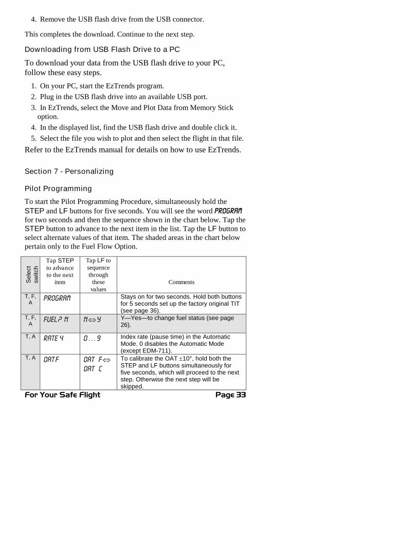
Pilot Programming
To start the Pilot Programming Procedure, simultaneously hold the
STEP and LF buttons for five seconds. You will see the word PROGRAMfor two seconds and then the sequence shown in the chart below. Tap theSTEP button to advance to the next item in the list. Tap the LF button toselect alternate values of that item. The shaded areas in the chart belowpertain only to the Fuel Flow Option.
Se
lect
sw
itch
Tap STEPto advanceto the next
item
Tap LF tosequencethrough
thesevalues
Comments
T, F,A
PROGRAM Stays on for two seconds. Hold both buttonsfor 5 seconds set up the factory original TIT(see page 36).
T, F,A
FUEL ? N NY Y—Yes—to change fuel status (see page26).
T, A RATE 4 0 … 9 Index rate (pause time) in the AutomaticMode. 0 disables the Automatic Mode(except EDM-711).
T, A OAT F OAT FOAT C
To calibrate the OAT 10°, hold both theSTEP and LF buttons simultaneously forfive seconds, which will proceed to the nextstep. Otherwise the next step will beskipped.

Page 34 Engine Data Management
T, A OAT0 OAT-I0 …OATI0
This step will be normally be skipped.
Adjust the indicated temperature up or downby up to 10°. For example, OAT3 adjust theOAT 3° higher.
T, A EGT I?N EGT I?NEGTI?Y
Y—Yes—sets the digital display to one-degree resolution; N—No—sets 10°. (10°resolution is easier to interpret the EGTs.)
HP - ? Y NY Y—Yes—displays %HP in the upper digitalwindow. N—No—displays RPM in the upperdigital window. Hold STEP and LF for 5seconds to adjust the horsepower constant.
T, A 70 HP
HPC= I25
%HP display will change when HP constantis adjusted. See Programming the EDM-800Horsepower Constant beginning page 35.Hold STEP and LF for 5 seconds to set theMAP calibration. Tap STEP to exit.
T, A MAP +0 Correct the MAP to the altimeter setting at a sealevel airport ±3.0 in Hg. Hold Step/OK andChange for 5 seconds until you see ADJUST toset the MAP calibration. Tap Step/OK tocontinue to the next step.
F, A KF-SET 29.00=KF KF-set, hold both STEP and LF buttonssimultaneously for five seconds to begin thenext sequence.
29.00=KF 29.00 One digit will be flash and the LFbutton will adjust up or down. STEP to nextdigit.
Hold both buttons to exit set mode.
F, A ACCUM?N ACCUM?NACCUM?Y
N—No—Upon informing the EDM that yourefueled the aircraft, reset total fuel used to0.Y—Yes—accumulate total fuel used ratherthan reset to 0 at each refueling.
F, A GPS - C = 2 0 … 6 GPS Com Format.
T, F,A
DUMP? N NNEWALL
Memory dump. Select to transfer ALL or
only NEW data. The END Y step is skippedafter a successful a Long Term MemoryDUMP.
T, F,A
END Y END Y END N
Y—Yes to exit; N—No to review list again.

For Your Safe Flight Page 35
Section 8 - Programming the EDM-800 Horsepower Constant
You must adjust the HP Constant once for your aircraft. The defaultdisplay will be RPM if Fuel Flow is not operational or you can adjust thedisplay to show RPM instead of HP. Before takeoff, put the EDM in theHP Constant mode. Enter the pilot program mode by simultaneouslyholding the STEP and LF buttons until the display changes, about 5seconds.
1. Tap STEP about 4 times until you see HP-? Y. If you see HP-? N,change the N to a Y by tapping the LF button, then hold both the
STEP and LF buttons display until you see HPC= I20. Change thenumber 120 by tapping or holding the LF button. Note that the %HPnumber in the display will change as you change the constant.
2. Referring to the Aircraft Flight Manual (AFM) set the engine to aconstant power setting of 70% , Rich of peak and maintain straightand level flight at any altitude below 10,000 feet. View the readingin the %HP display and see how close it is to your current enginepercent HP. If the value in the display not at your current enginepercent HP setting, then change the HP reading by adjusting the HPconstant in the lower display by holding or tapping the LF button.Note: the reading is the percent of maximum HP, not total HP.
3. Keep adjusting the HP constant until the upper window displays thesame power level as the current engine percent HP.
4. Tap the STEP button to exit.
Section 9 - Programming Manifold Pressure (MAP)
Do this one time and only if the MAP on your manifold pressuregauge doesn't match the MAP shown on the EDM-800.
1. Do this on the ground with the engine turned off.
2. Enter the pilot program mode by simultaneously holding the STEPand LF buttons for five seconds.
3. Tap STEP to index to HP-? Y.
4. Hold both the STEP and LF buttons and you will see HPC= I25.
5. Hold both the STEP and LF buttons and you will see MAP= 0
6. Use one of the following two methods to calibrate the MAP.

Page 36 Engine Data Management
You may need to correct the MAP based on the altimeter setting at asea level airport.
A. Enter the pilot program mode by simultaneously holding the Step
and LF buttons for five seconds.
B. Tap Step/OK repeatedly until you see—for example—HPConstant=125. Then hold both the Step/OK and Change buttonsdisplay until you see Adjust, followed by HP Constant=125.
C. Again, Hold both the Step/OK and Change buttons display until
you see ADJUST, followed by MAP=0. The adjustment range forthe MAP is ±3.0 in Hg.
D. Adjust the MAP based on the altimeter setting at a sea levelairport using the Change button.
E. Tap the Step/OK button to proceed to the next step.
OR
F. Absolute calibration: the table below shows the MAP for a givenfield elevation (down the left side of the table) and altimetersetting (along top row of the table). Find the entry in the tablemost closely matching your field elevation and current altimetersetting. Interpolate if necessary. Use the LF button to index upor down when adjusting the MAP
Alt setting->field elev.
29.0 29.2 29.4 29.6 29.8 29.9 30.0 30.2 30.4 30.6 30.8 31.0
0 29.0 29.2 29.4 29.6 29.8 29.9 30.0 30.2 30.4 30.6 30.8 31.01000 28.0 28.2 28.4 28.5 28.7 28.8 28.9 29.1 29.3 29.5 29.7 29.92000 27.0 27.1 27.3 27.5 27.7 27.8 27.9 28.1 28.3 28.5 28.6 28.83000 26.0 26.2 26.3 26.5 26.7 26.8 26.9 27.1 27.2 27.4 27.6 27.84000 25.0 25.2 25.4 25.6 25.7 25.8 25.9 26.1 26.3 26.4 26.6 26.85000 24.1 24.3 24.5 24.6 24.8 24.9 25.0 25.1 25.3 25.5 25.6 25.86000 23.2 23.4 23.6 23.7 23.9 24.0 24.0 24.2 24.4 24.5 24.7 24.87000 22.4 22.5 22.7 22.8 23.0 23.1 23.1 23.3 23.5 23.6 23.8 23.9
Do not set MAP to the local altimeter (Kollsman window)setting since that setting is the pressure at sea level, and isnot the same as your field elevation pressure.
Tap or hold the LF button to change the MAP value.
7. Tap the STEP button to exit.
Section 10 - Programming use of Factory Original TIT Probe
If your aircraft is using the factory original TIT probe and gauge, youshould calibrate the EDM for that probe. The factory original TIT probemust be a type K and the leads must be wired red-to-red and yellow-to-

For Your Safe Flight Page 37
yellow. Both the EDM and factory original gauge may be usedconcurrently. Due to the high input impedance of the EDM instrument, itwill not affect the accuracy of the factory installed probe or gauge.
In normal cruise flight, record the difference between the factoryinstalled TIT gauge and the EDM TIT reading.
TIT gauge ________ EDM ________.
If you haven’t already done so, start the pilot programming procedure,by simultaneously holding the STEP and LF buttons for five seconds.
You will see the word PROGRAM for two seconds.
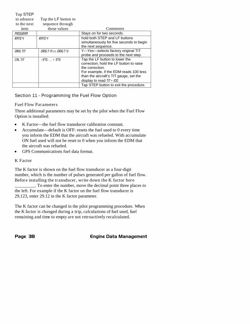
Page 38 Engine Data Management
Tap STEPto advanceto the next
item
Tap the LF button tosequence through
these values CommentsPROGRAM Stays on for two seconds.
RATE 4 RATE 4 hold both STEP and LF buttonssimultaneously for five seconds to beginthe next sequence.
ORIG TIT ORIG T-N ORIG T-Y Y—Yes—selects factory original TITprobe and proceeds to the next step.
CAL TIT - 975 … + 975 Tap the LF button to lower thecorrection; hold the LF button to raisethe correction.For example, if the EDM reads 100 lessthan the aircraft’s TIT gauge, set thedisplay to read TIT + I00.Tap STEP button to exit the procedure.
Section 11 - Programming the Fuel Flow Option
Fuel Flow Parameters
Three additional parameters may be set by the pilot when the Fuel FlowOption is installed:
K Factor—the fuel flow transducer calibration constant. Accumulate—default is OFF: resets the fuel used to 0 every time
you inform the EDM that the aircraft was refueled. With accumulateON fuel used will not be reset to 0 when you inform the EDM thatthe aircraft was refueled.
GPS Communications fuel data format.
K Factor
The K factor is shown on the fuel flow transducer as a four-digitnumber, which is the number of pulses generated per gallon of fuel flow.Before installing the transducer, write down the K factor here_________. To enter the number, move the decimal point three places tothe left. For example if the K factor on the fuel flow transducer is29,123, enter 29.12 in the K factor parameter.
The K factor can be changed in the pilot programming procedure. Whenthe K factor is changed during a trip, calculations of fuel used, fuelremaining and time to empty are not retroactively recalculated.

For Your Safe Flight Page 39
Fine Tuning the K Factor
The K factor shown on the fuel flow transducer does not take intoaccount your aircraft’s particular installation. Fuel hose diameters andlengths, elbows, fittings and routing can cause the true K factor to bedifferent from that shown on the fuel flow transducer.
You must use the following procedure to fine tune the K factor.
1. Make at least three flights of about two to three hours each. Note theactual fuel used (as determined by topping the tanks) and the EDMcalculation of the fuel consumed for each flight = USD.
FlightFuel USED shown by EDM
(total tank - REM) Actual fuel used by topping tanks
123
Total
2. Total the EDM fuel used and the actual fuel used.
3. Record the current K factor here____________________ and inthe table below.
4. Calculate the New K Factor as follows:
New K Factor = (EDM fuel used) x (Current K factor)(actual fuel used)
New K Factor = ( ) x ( )( )
Every time you fine tune the K factor, record the measurements here:
DateEDM
fuel usedactualfuel used
Current Kfactor
New K factor=x/
Pilot’sinitials

Page 40 Engine Data Management
Fuel Flow Option Programming Procedure
Setting the K factor
This procedure is different than for setting other parameters. Place theselect switch in the FF position. If you haven’t already done so, start thepilot programming procedure, simultaneously hold the STEP and LFbuttons for five seconds. You will see the word PROGRAM for two seconds.
1. Tap STEP button to advance to the KF-SET screen 29.00=KF2. Hold both the STEP and LF buttons simultaneously for five seconds.
First digit flashes (shown here as a larger digit only for illustration
purposes): 29.00
3. Tap or hold the LF button to change flashing digit: I 9.00
4. Tap STEP button for next digit: I 9.00
5. Tap or hold the LF button to change flashing digit: I 8.00
6. Tap STEP button for next digit: I8.007. Repeat items 5 and 6 for the remaining two digits.8. Hold STEP and LF buttons simultaneously for five seconds to exit.
Accumulate Total—Trip Total
Select “No” if you wish to display total fuel used since the last time youinformed the EDM that the aircraft was refueled. Select “Yes” to displaytotal fuel used for an extended trip with multiple fuel stops. Thisselection affects only the USD parameter.
GPS-C Comm settings
The GPS-C setting selects the format of the fuel data output of the EDM.See “
GPS-C Fuel Flow Format” on page 46.
Section 12 - Programming Long Term Data Memory
If you haven’t already done so, start the pilot programming procedure,simultaneously hold the STEP and LF buttons for five seconds. Youwill see the word PROGRAM for two seconds. To change the date, time anduser id for the Long Term Data Memory, tap the STEP button until thedisplay shows DUMP? N. Next, simultaneously hold the STEP and LFbuttons for five seconds. Then set the date and time as show below:

For Your Safe Flight Page 41
STEP LF Comments
TIME 2500 Record time interval, in seconds
MNTH I I2 Month
DAY I 3I Day
YEAR 8079 Year (note: represents 1980 through 2079)
HOUR OO 23 24 hour time. We suggest you set Zulu time
MIN OO 59 This also zeros the seconds
N----- N I23456Current Aircraft ID. To change Aircraft ID, hold bothSTEP and LF buttons until the first character flashes.LF selects the first character. STEP moves to the nextcharacter. To Save, hold both STEP and LF for 5 sec.
END Y Tap STEP button to exit the procedure.
Section 13 - EDM-711 Primary Alarm Display
The EDM-711—There are 3 primaryfunctions available to your EDM-700/800 CHT, OIL and TIT. When anEDM-700-800 has primary functions it iscalled an EDM-711. A Remote alarmlamp is supplied that will function evenwhen the primary display fails. Each lamp is a dual lamp Red/Yellow.The lamp will light when the indicated temperature exceeds alarm limit.The limits for these alarms and warnings are preset by the factory foryour type of aircraft and can only be changed at the factory. The yellowwarnings are set as follows: CHT 45°F below redline, OIL 25°F belowredline, and TIT 100°F below redline.
Tapping STEP will extinguish the flashing digital display but theremote yellow/red warning indication cannot be extinguished.
In the procedure in the next section to change the alarm limits, you willnot be able to change the limits for CHT, OIL or TIT.
R/Y
460F 230F 1650F
Engine Temperature Limit
CHT OIL TIT
R/Y R/Y R/Y

Page 42 Engine Data Management
Section 14 - Alarm Limits
Factory Set Default Limits—Non-Primary
JPI conservatively sets the default alarm limits below Lycoming andContinental recommendations.
Parameter Default Low Limit Default High Limit Alarm ExampleCHT 450°F* 230°C 465 CHTOIL 90°F 32°C 230°F* 110°C 280 OILTIT 1650°F* 900°C I 720 TITCLD -60°F/min. -33°C/min. -65 CLDDIF 500°F 280°C 525 DIFBAT, 24 V 24V 32V 22 .4 BATBAT, 12 V 12V 16V I7.6 BATMAP 32 inches 46.3 MAPLO FUEL 45 min 00.20 H.MLO TIME 10 gal, kg, ltr, lbs 7.2 REM
The alarm limits may differ from those shown here, depending on your type of aircraft.
If you change the display between Fahrenheit and Celsius, newerinstruments will automatically change the alarms to the factory limits.
When an alarm is displayed, tapping the STEP button will temporarilydelete that parameter from the sequence for the next ten minutes. Whenan alarm is displayed, holding the STEP button until the word OFFappears will delete that parameter from the sequence for the remainderof the flight. On EDM-711 primary instruments the red alarm lightcannot be extinguished as long as the alarm condition is present.
Changing the Alarm Limits/Tank Capacity
You may prefer to set your own alarm limits or change your usable fuelin the main tanks. Follow the procedure outlined below to change any ofthe factory default settings.
To start the alarm limit procedure, after power up, wait until the EDMcompletes its self test and is in the Automatic or Manual mode. If indoubt, tap the STEP button a few times. Then follow the steps depictedhere:

For Your Safe Flight Page 43
Hold bothbuttons for 5seconds until
the words
FAC LIM
Tap STEPbutton untilthe words
END Y
Hold bothbuttons for 5seconds until
the word
PROGRAM
The display will then sequence as shown in the chart below. Tap theSTEP button to advance to the next item in the list. Tap the LF button toselect alternate values of that item. Hold the LF button to increase anumerical value; tap the LF button to decrease a numerical value. Theshaded areas in the chart below pertain only to the Fuel Flow Option.
Procedure for changing the larm limits or main tank capacity:
Tap STEPto next item
LF sequences throughthese value ranges Description
FAC? N FAC? NFAC? Y Restore factory defaults?
ENG F ENG FENG C Select F or C degrees forall engine temps. Youmust also change thealarm limits to °F or °C.
I6.0 H BAT I0.0 H BAT … 35.0 H BAT Battery high voltage limit,set in 0.5 volt increments.
I2.0 L BAT 8.5 L BAT … 30.0 L BAT Battery low voltage limit.
500 DIF 30 DIF … 990 DIF EGT difference limit, set in10° increments.
450 H CHT 90 H CHT … 500 H CHT CHT high limit, set in 5°increments.*
-60 CLD -5 CLD … -200 CLD Cooling limit, set in5°/min. increments.
I650 TIT 650 TIT … 2000 TIT Also sets the maximumscale of the EGT and TITbar graph.*
230 H OIL 40 H OIL … 500 H OIL Oil temperature high limit,set in 5° increments.*
90 L OIL I0 L OIL … 250 L OIL Oil temperature low limitset in 5° increments
42.0 MAP 25MAP … 90 MAP MAP overboost alarm(EDM-800 only)

Page 44 Engine Data Management
FUEL GAL FUEL GALFUEL KGSFUEL LTRFUEL LBS
Selects the units in allparameters where fuelquantity or fuel rate isdisplayed
MAIN=50 MAIN=0 … MAIN=999 Main tank capacity, inunits selected
AUX? N AUX? NAUX? Y Y—Yes—aircraft hasauxiliary tanks
AUX=0 AUX=0 … AUX=250 Auxiliary tank capacity
MIN =45 MIN =0 … MIN =60 Alarm limit in minutes forlow time in tanks
REM =I0 REM =0 … REM =200 Alarm limit for low fuelquantity in tanks, in unitsselected
CARB? CARB? NCARB? Y
Y—Yes—carburetedengine. Setting 1-3, 3being high filter
RECRD? RECRD? Y RECRD? N Long Term Memory.Y—only data recording.N—only real-time dataoutput.
CYL=6 CYL=4 … CYL=I 2 (EDM-800 only) Set thenumber of cylinders. Seepage 45 for exceptions.
HP = I 80 HP=60 … HP=500 (EDM-800 only) Set theHP constant
I 4.90 = EC I 2.00= EC… I6.00= EC (EDM-800 only) Set theEngine Constant
END YEND N Y—Yes to exit; N—No toreview list again
MAP, Fuel Flow Alarm Limits, Units, Fuel Capacity
MAP Overboost Alarm
Enter the redline for overboost on turbocharged engines.
Fuel Flow Units (shaded area above)
Selects the units in all measurements where fuel quantity or fuel rate isdisplayed. If you change this parameter, it does not change the numericalvalue of the fuel tank capacity. You must do this manually. For exampleif you change from Gal. to Lbs., the tank capacity will be interpreted as50 Lbs. rather than 50 gallons; the EDM will not convert 50 Gal toequivalent pounds.
Main Tank Capacity
Enter the total usable fuel capacity of the main tanks in the fuel flowunits selected.

For Your Safe Flight Page 45
If you do not have auxiliary tanks or tank tabs, answer “No.” If youanswer “Yes,” you will be asked to input the capacity of the auxiliarytanks in the fuel flow units selected. If you have tank tabs and sometimesfill only to the tabs, set the auxiliary tank capacity to the differencebetween full tank capacity and tab capacity. The EDM does notdifferentiate fuel flow between the main and auxiliary tanks; it tracksonly total fuel in the aircraft.
Low Time Alarm Limit
Select the value of the time remaining, in minutes, that triggers thealarm. Time remaining is calculated at the current fuel flow rate.
Low Fuel Alarm Limit
Select the value of the fuel remaining, in the selected fuel flow units,that triggers the alarm. Fuel remaining is calculated at the current fuelflow rate.
Carburetor?
Different response filters are used depending on whether your engine iscarbureted or fuel injected. The filter for a carbureted engine has aslower response time to reduce sudden fluctuations in readings. Thehigher the number the more filtering or less jumping around.
Number of Cylinders
This applies only to EDM-800. Set CYL = 4 or 6 depending on yourengine. Exceptions:
4 cylinder engine with dual (all-in-one) magnetos set to CYL= 8.
4 cylinder Lasar® ignition set to CYL=8.
6 cylinder Lasar® ignition set to CYL=I2.
HP and EC (EDM-800 only)
These adjustments set the parameters for the HP calculations in theEDM. Set the Rated HP for your particular aircraft. Set the HPConstant to 14.9 for normally aspirated or turbo normalized engines; setit to 13.75 for turbo boost engines. To set the EC, hold STEP and LF forfive seconds. The first digit will flash. Use LF to change the digit, useSTEP to advance to the next digit. Hold STEP and LF for five secondsto exit.

Page 46 Engine Data Management
Initially Entering the Tank Capacity
To initialize or change the tank capacities, hold the STEP button whileturning on the power to the EDM. The following program steps will bedisplayed:
Tap STEPto advance
Tap the LF button to sequencethrough these values Comments
MAIN=50 MAIN=0 … MAIN=999 Main tank capacity, inunits selected
AUX? N AUX? NAUX? Y Y—Yes—aircraft hasauxiliary tanks
AUX=0 AUX=0 … AUX=250 Auxiliary tank capacity
Navigation Data Formats
Output of any GPS; input to EDM. The EDM automatically configuresitself for one of three industry standard data formats: Set handheldGPS to output MEA-183.
Format Baud rate
NMEA-183(Marine NavData Format)
4,800 This is the format for most handheld GPS receivers.Loran must have sentences RMA & RMB. GPS musthave sentences RMB & RMC.
Aviation DataFormat
9,600 “Output sentence type 1” Required sentences are: A, B,C, D, E, I and L first character identifier byte. Sentenceterminator may be either <CR><LF> or <CR> alone.
Northstarbinary
1,200 M1 setup select “NO EXTENDED”, “NAV ONLY”
GPS-C Fuel Flow Format for GPS Bi-directional Comm
GPS-C Input to GPS; output of EDM0 No fuel data output1 Garmin (Shadin Miniflow format)2 Allied Signal (format B) “To waypoint only”3 Arnav/EI fuel data4 Allied Signal (format C) *5 (Not used)6 Garmin 430/530 GNX-80/GX-60 “To waypoint only”
7 Garmin 430/530 GNX-80/GX-60 “To Destination only”8 Allied Signal (format B) “To Destination only”

For Your Safe Flight Page 47
Diagnostic Messages, Fuel Flow
The following displays indicate a malfunction in the Fuel Flow Optiontransducer or associated electrical connections:
0.0 GPH Zero’s indicate Fuel flow is too low to register
--- GPH Dashes indicate No fuel flow transducer signals
--- H.M Dashes indicate No fuel flow transducer signals
GPS Interface Diagnostics
Parameters REQ, RES, & MPG are allmissing from the scan.
No communications from GPS receiverto EDM. Possibly no connection oraircraft GPS is off.
NO - COM message and parameters
REQ, RES, & MPG are missing.
Communications are received by EDMand the Auto-Protocol setup is inprocess. Verify correct output formatsetup in GPS receiver; check GPSconnections.
NO - SIG message and parameters
REQ, RES, & MPG are missing.
GPS receiver has insufficient signal forvalid data.
NO - WPT message and parameters
REQ & RES, are missing.
No waypoints are programmed into theaircraft GPS receiver.
- - - REQ or - - - RES message Your ground track is more than 70°from your course to the next GPSwaypoint.
Navigation Data Ports for GPS Comm
(These ports are completely independent of the EDM serial data outputport.)
Navigation Data (output of GPS; input to EDM)
Compatible with RS-232, TTL, RS-423, RS-422 SDA.
Serial data format: 8 data, 1 start, no parity. Baud rates: 1,200,4,800, or 9,600 depending on the GPS data output format. The EDMautomatically detects the GPS data output format and is independentof the GPS-C setting.

Page 48 Engine Data Management
Fuel Data (input to GPS; output of EDM)
RS-232. Serial data format: 8 data, 1 start, no parity. Baud rate:9,600.
Output format is determined by the GPS-C setting, but may be over-ridden by the GPS navigation format: If the EDM senses Northstaror NMEA-183 navigation data input, there will be no fuel dataoutput.
Section 15 - Option Connector Pin Assignments
P1 (upper) 25-pin connectorfor 4 or 6 cylinder engines.See installation manual for7, 8, 9 cylinder instruments
MAP-RPM 9-pinconnector (EDM-800)
Fuel Flow Option15-pin connector
Pinno.
Pinno.
Probe orfunction
Pinno.
Function/sensor pin
Pinno.
Function
yel 1 red 2 OIL grn 1 RPM sig /1 1 RS-232out
yel 3 red 4 IAT blk 2 RPM grd /2 2 RS-232in
yel 5 red 6 CARB(or CDT)
red 3 RPM pwr /3 wht 4 FF signal
yel 14 red 15 OAT red 4 MAP pwr /3 red 5 FF power
yel 16 red 17 TIT blk 5 MAP grd /1 blk 6 FF return
yel 18 red 19 TIT-2(2
ndTIT)
6 (not used) 7 Switchcom
gry 12 Remotealarm
7 (not used) 8 SwitchEGT
red 13 + Power14/28 vdc
wht 8 MAP sig+ /2 9 SwitchFF
wht 24 RS-232data port
grn 9 MAP sig- /4 11 RemoteFF alarm
blk 25 Groundat Engine
Interface connections to selected GPS modelsEDM Fuel flow conn Pin 1 Fuel flow conn Pin 2Arnav 5000 Pin 4 Pin 5Garmin 195 (nc) Pin 4Garmin 430 / 530 Pin 57 Pin 56Northstar M3P (nc) Pin 6 (leave pin 11 open)UPS GX50 / 60 Pin 4 Pin 5

For Your Safe Flight Page 49
Section 16 - Reference Reading
You may wish to know more about the effect of engine operations onEGT and CHT. The reading list below provides general overviews aswell as original references on topics that may be of interest.
General Overview
These references are readily available to pilots and provide a readablesource of general technical information.
Teledyne Continental Motors, Engine Operation for Pilots, from theFAA Accident Prevention Program, FAA-P-8740-13.
Editors of Light Plane Maintenance Magazine, EGT Systems,Belvoir Publications Inc., Greenwich, CT 06836. 1989.
Lycoming Flyer Issue 53 dated January 93.
Technical Reviews and Original References
For those pilots who have engineering backgrounds, the references listedbelow present the original research on the combustion process andrepresent the source documents for those with technical interests.
A. Hundere, “Autogas for Avgas,” AOPA Pilot, October, 1969.
A. Hundere and J. Bert, “Pre-ignition and Its Deleterious Effects inAircraft Engines,” SAE Quarterly Transactions, Vol. 2, No. 4, pages547-562, October 1948.
Section 17 - Technical Support
JPI offers both e-mail ([email protected]) and telephone technicalsupport. Have your model and serial number ready when you call. Call
JPI for a return authorization number RMA before returning anyequipment.
J.P. INSTRUMENTS Inc.
3185 B AirwayCosta Mesa, CA 92626
800 345-4574
714 557 3805
Fax 714-557-9840
www.jpinstruments.com and www.jpitech.com

Page 50 Engine Data Management
Limited Warranty
J.P. Instruments Inc. (JPI) warrants all parts in your new EDM to be freefrom defects in material and workmanship under normal use. Ourobligation under this warranty is limited to repair or exchange of anydefective part of this unit if the part is returned, shipping prepaid, withinthree years for electronics and one year for probes from the date oforiginal purchase. Installation labor is the responsibility of the aircraftowner. Homebuilt aircraft warranty starts when the aircraft is certifiedfor flight. Replacement parts carry a warranty for the balance of thewarranty period.
Under this warranty, JPI is not responsible for any service charges,including removal, installation, nor any other consequential damages.JPI incurs no obligation under this warranty unless a WarrantyRegistration Certificate describing the warranted product has beencompleted and mailed to JPI with all information requested.
This warranty is void on any product which has been subject to misuse,accident, damage caused by negligence, damage in transit, handling ormodification which, in the opinion of JPI, has altered or repaired theproduct in any way that effects the reliability or detracts from theperformance of the product, or any product whereon the serial numberhas been altered, defaced, effaced or destroyed.
This warranty is in lieu of all other warranties expressed or implied andother obligations of liability on JPI’s part, and it neither assumes norauthorizes any other person to assume for JPI any other liability inconnection with the sale of JPI products.
To initiate this warranty, the aircraft owner must submit a completedData Logging Worksheet to JPI. Upon receiving a completed worksheet,JPI will initiate the warranty from the date of original purchase. Anyreplacement parts carry a warranty that extends for the balance of theperiod of the original warranty. For homebuilt aircraft the warranty startswhen the aircraft is certificated for flight and noted on the warranty card.

For Your Safe Flight Page 51
Index
A
Accumulate, 34, 39total, 27
Adapter probe, CHT, 21Adding fuel, 27Adjusting
K-factor, 37OAT, 34TIT, factory original, 36
Alarm Display Lights, 40Alarm limits
changing, 41factory defaults, 41fuel flow, 43
Alarms, 24low fuel, 44priority, 25resetting, 25
ALL, 34select switch, 26
Allied Signal, 45Arnav, 45Automatic indexing mode, 7Automatic mode, 11AUX, 43, 45Auxiliary tanks, 43Avgas, 25Aviation data format, 45
B
Bar graph, 4column resolution, 6EGT, 6
Baud rate, 46Blinking display, 13, 17, 24, 25Brightness, display, 7Buttons
front panel, 8
C
CAL ERR, 11Calibration
horsepower, 35internal self test, 11K-factor, 37
manifold pressure (MAP), 35OAT, 34TIT, factory original, 36
Capacity, fuel tank, 26CARB?, 43Carburetor, 44
ice, 23temperature, 10, 29
Celsiusdisplay indicator, 5engine temperatures, 42OAT, 33
Changing alarm limits, 41CHT
missing segment, 6probe, 2, 21too high or too low, 21, 24
CLD. See Shock coolingClimb, 18Combustion, 2, 25, 48Compression, 2, 23
high, 25low, 22
Compressor discharge temperature,CDT, 10, 29
Connectoroption pins, 47
Cooling. See Shock coolingCowling, obstruction, 23Cruise, 19Custom programming, 33
alarm limits, 41fuel flow option, 37Long Term Memory Option, 39
Cylinder numbers, 6
D
DataGPS formats, 45ports, GPS, 46
Default alarm limits, 41Defueling, 27Descent, 19Detonation, 24, 25Diagnosing engine problems, 21, 36,
37, 41Diagnostic
fuel flow messages, 46GPS interface messages, 46

Page 52 Engine Data Management
self test, 11DIF, 10, 24, 29, 42Dimming, display, 7Display, 4
analog, 4digital, 6flashing, 13, 17, 24, 25
Dot index, 6Download, 31
E
Economy, best, 3EDM-711, 40EGT
alarms, 24loss, 22probe, 2resolution, display, 34select switch, 26too high, 20, 22too low, 20, 23
Electronics International, 45Engine
diagnosis chart, 22limits, normal, 21run-up, 18
Enunciator, alarm, 24Exclude parameters, 11Exhaust leak, 18, 24EzPlot, 31
F
Factory default alarm limits, 41Factory original TIT probe, 36Fahrenheit
display indicator, 5engine temperatures, 42OAT, 33
Failure to pre-lean, 20FF, select switch, 26Fill options, 27FILL? N, 26FILL+, 27First cylinder to peak, 13Flash drive, 31Flashing
segment, 6Flashing display, 13, 17, 24, 25Flat EGT response, 24
Fouled spark plugs, 5Fuel
accumulate, 27adding or filling, 27auxiliary tank capacity, 43capacity, 26, 43injectors, 24injectors, clogged, 2, 18, 23Octane, 24pump, 24remaining, 29required, 29reserve, 29resetting fuel used, 28start up, 26tabs, tank, 43tank capacity, 26, 43used, 29
Fuel flowalarm limits, 43connector, 47diagnostics messages, 46units, 43
Full throttle, 18
G
Gallons per hour, 29GAMI, 12, 13, 15, 16Gasket probe, 21Gasket, manifold, 18, 24GPH, 29GPS
comm settings, 39constant, 34data formats, 45data ports, 46GPS-C, 34interface diagnostics, 46
H
H.S, 29Hastaloy, 17HBAT, 42HCHT, 42HOIL, 42Holding a button, 8Horsepower
constant setting, 34, 35

For Your Safe Flight Page 53
I
Ice, carburetor or induction, 23Ignition, 24
timing, 22Include parameters, 11Index dot, 6Indexing
rate, 37sequence, 29
Induction, 23air temperature, IAT, 10, 29
Informing the EDM-700startup fuel, 26
Initial tank capacity, 45Injectors. See Fuel, injectorsIntake valve, 22
K
K-factorchanging, 34, 39determing, 38
KPH, 29
L
LBAT, 42Leak
manifold, 24Leak, manifold, 18Lean of Peak, 15Lean of Peak Leaning, 15Leanest cylinder, 13LeanFind
button, 8description, 8mode, 12procedure, 13
Leaning, 3, See also, LeanFindby TIT, 16pre-leaning, 14too quickly, 20
LF. See LeanFindLights
Alarm Display, 40LOIL, 42Long Term Memory Option
mark, 30operation, 30
Lotus 123, 30
Low fuel alarm, 44LPH, 29
M
Magneto check, 18MAIN, 43, 45Manifold Air Pressure (MAP)
calibration, 35Manual indexing mode, 7Manual mode, 12Mark, 30Memory box, 31Methods
leaning, 12Miles per gallon, 29Misapplications, 20Missing
column, 22segment, 6
Mixture, 3, 13best economy, 3best power, 3
Modes, 7, 11MPG, MPK, MPL, MPP, 29MS Excel, 30
N
Nautical miles per gallon, 29Navigation data formats, 45NEW, 34NMEA-183, 45NO COM, 46NO SIG, 46NO WPT, 46Normal engine limits, 21Normalize view, 5Northstar binary format, 45NRM, 5
O
OATcalibration, 34F or C, 33
Octane, 24OFF, 8, 25, 41Off-scale EGT bars, 20Oil
flashing segment, 6

Page 54 Engine Data Management
missing segment, 6OIL, 10, 29Oil temperature, 10, 29OPEN PRB, 11Operation
fuel flow option, 26temperature scanner, 4
Option connector, 47Outside air temperature. See OAT
P
PanelAlarm Display, 40
Parameter indexing, 9, 28Peak EGT, 13PEAK EGT, 13, 15Percentage view, 5Pilot programming, 33
alarm limits, 41data recording, 39fuel flow option, 37
Pin assignments, option connector, 47Power, best, 3PPH, 29Pre-ignition, 23, 25Pre-leaning. See Leaning, pre-leaningPrimary
Alarm Display, 40Priority, alarm, 25Product support, 48Programming, 33
alarm limits, 41data recording, 39fuel flow option, 37
R
Range, normal temperature, 21Rate
baud, 46fuel flow, 28, 29indexing, 37shock cooling, 19
Real-time, 43Record, on, off, 43Recording. See Long Term Memory
OptionRECRD?, 43Red line, 21Reference reading, 48
REM, 29Removing fuel, 27REQ, 29RES, 29Reset
alarm limits, 41alarms, 25fuel used, 28
Resolution, EGT display, 34Rich of Peak, 12Rough engine, 22RS-232, 46Run-up, 18
S
Scanning. See IndexingSegment
flashing, 6Select switch, 26Self-test, 11, See also DiagnosticSetting the K factor. See Fuel FlowSetup, 33
alarm limits, 41fuel flow option, 37Long Term Memory Option, 39
Shadin Miniflow, 45Shock cooling, 10, 12, 19, 21SNAP, 30Spark plug
fouling, 5, 18, 22Startup
diagnostics, 11fuel, 26
STEP button, 8Stuck valve, 22Switch, select, 26
T
Tabs, tank, 43Take-off, 18Tank capacity
entering at power up, 45Tanks, fuel
capacity, 26, 43tabs, 26, 43
Tapping a button, 8Technical support, 48Test, self, 11Time to empty, 29

For Your Safe Flight Page 55
Timing, ignition, 22TIT, 10, 16
factory original probe, 36missing segment, 6
Toggle, N, P, 5Top fuel tanks. See FillTotal fuel, 27
used, 29Transducer, fuel flow, 28Turbocharged Engines, 16
U
Uniform, CHT, EGT not, 23Units, fuel flow, 43USB
port, 32USD, 29
V
Valvelifter, 22stuck, 22
Vapor, 24View
change diagram, 9normalize, percentage, 5
Voltage, 10, 29
W
Warranty, 49
Z
Zeroing fuel used, 28

Page 56 Engine Data Management
Quick Reference Guide
Normalize View Hold LF for three seconds.
Percentage View Hold LF for three seconds.
Automatic Scan1. Tap LF.2. Tap STEP.
Exclude Parameter in AutomaticScan (except EDM-711)1. Tap STEP to index to the
parameter to exclude.2. Tap both STEP and LF.3. See decimal point before
parameter name to exclude.
Change Indexing Rate1. Hold both STEP and LF until
the display shows PROGRAM,
followed by FUEL? N.
2. Tap STEP and see RATE 4.3. Tap LF to change the number:
1 through 9 is the pause timeduring automatic indexing.0 sets to never index (exceptEDM-711).
4. Tap STEP until you see END Y,then tap STEP to exit
Mark Data in Memory Tap LF twice.
Reset Fuel Used to zero in flight1. Tap STEP and see USD.2. Hold both STEP and LF until
the display shows .0 USD
Transfer Data in Memory1. Connect PC Computer to the
EDM serial port.2. Hold both STEP and LF until
the display shows PROGRAM,
followed by FUEL? N.3. Tap STEP a few times until
you see DUMP? N.
4. Tap LF until you see DUMP NEW
or DUMP ALL.5. On the PC Computer click on
the Start button6. On the EDM tap STEP to
transfer. (to abort hold STEPand LF for 5 seconds).
7. On the EDM see SAVE D?N.8. If save was successful, tap LF
to see SAVE D?Y.
9. Tap STEP to exit.
Initially Entering TankCapacity
To initialize or change the tankcapacities, hold the STEPbutton while turning on thepower to the EDM. Thefollowing program steps will bedisplayed:
MAIN=50 Main tank capacity,in units selected
AUX? N Y—Yes—aircrafthas auxiliary tanks
AUX=0 Auxiliary tankcapacity
Tap STEP to advance to thenext item. Hold LF to increase ortap LF to change the amount.

For Your Safe Flight Page 57
Filled TanksIn flight, do this first (on power up,skip to step 4):1. Hold both STEP and LF until
the display shows PROGRAM,
followed by FUEL? N.
2. Tap LF to see FUEL? Y.3. Tap STEP
4. See FILL? N. Tap LF to see
FILL 75*5. With aux tanks or tabs, tap LF
again to see FILL I20*6. Tap STEP to exit.
Added or Removed FuelIn flight, do this first (on power up,skip to step 4):1. Hold both STEP and LF until
the display shows PROGRAM,
followed by FUEL? N.
2. Tap LF to see FUEL? Y.3. Tap STEP.
4. See FILL? N. Tap LF 2 or 3 times
to see FILL+.
5. Tap STEP and see .0 GAL.6. Hold LF to increase or tap LF
to decrease the amount of fueldisplayed.
7. Tap STEP to exit.
Reset Alarm (except EDM-711) Temporary reset (next 10
minutes): tap STEP. Reset for remainder of flight:
hold STEP until the word OFFappears.
Leaning Rich of Peak1. Pre-lean mixture and wait 1
minute.
2. Tap LF and see LEAN R.3. Lean mixture until you see a
column flash and the words
LEANEST followed by
I545 SET*
4. Hold LF and see I560 PK*or
I560 I3.5*, the peak EGT of thefirst cylinder to peak and fuelflow.
5. Enrich mixture to set desiredtemperature.
Leaning Lean of Peak1. Pre-lean mixture and wait 1
minute.
2. Tap LF and see LEAN R.3. Hold both STEP and LF until
you see LEAN L4. Lean mixture until inverted
columns.5. Continue leaning until you see
a column flash. You will seethe temperature below peak ofthe last cylinder to peak andthe fuel flow.
6. Hold LF to see I560 I.0* to seepeak EGT of the first cylinderto peak and the delta fuel flow(GAMI spread).
7. Lean mixture to set desiredtemperature.
* Values will vary depending on yourindividual installation.