ee 742 – chap 4 electromagnetic phenomenoneebag/chap 4.pdf · · 2011-09-20simple r‐l circuit...
TRANSCRIPT

EE 742 – Chap 4Electromagnetic Phenomenon
Y. Baghzouz
Fall 2011
Introduction
• This chapter addresses the electromagnetic interactions that occur within a generator immediately following a disturbance.
• These dynamics have a time scale of several milliseconds – a time period where the inertia of the turbine and generator is sufficient to prevent any change in rotor speed.
• Will consider various types of faults, round and salient pole generators, and when a generator is synchronized with the grid.

Fundamentals• Law of constant flux linkage: The magnetic flux linking in a closed
winding cannot change instantly, → the current through an inductor and the energy stored in it cannot change instantly.
• In the simple DC circuit below: – The circuit was at steady‐state, when the switch (make‐before‐
break) is activated.
– The current through the inductor starts from i0 then decays exponentially.
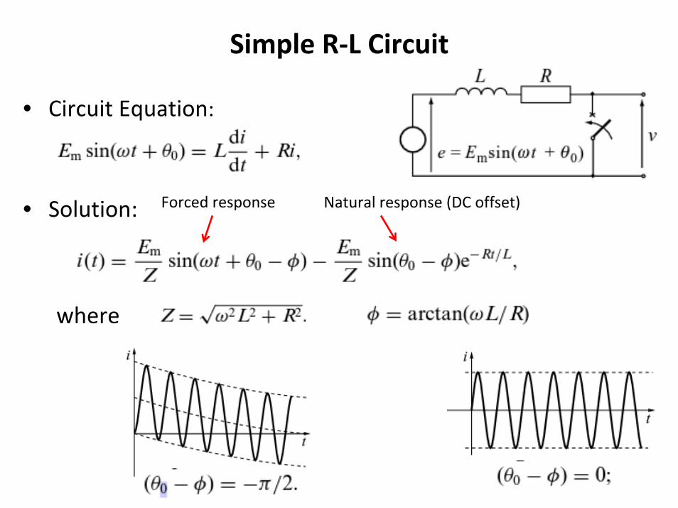
Simple R‐L Circuit
• Circuit Equation:
• Solution:
where
Natural response (DC offset)Forced response
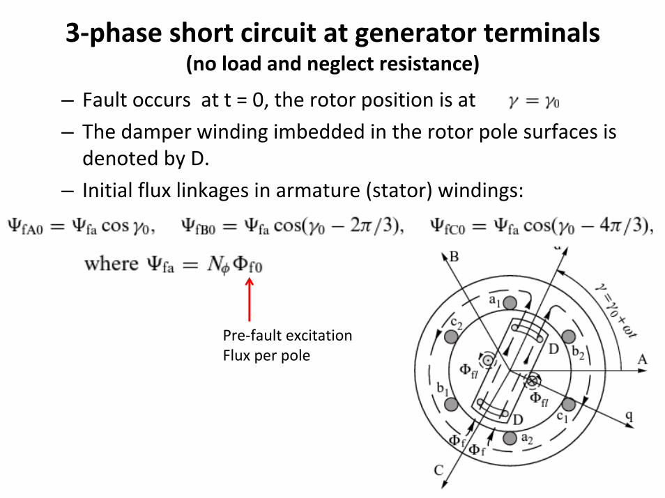
3‐phase short circuit at generator terminals(no load and neglect resistance)
– Fault occurs at t = 0, the rotor position is at
– The damper winding imbedded in the rotor pole surfaces is denoted by D.
– Initial flux linkages in armature (stator) windings:
Pre‐fault excitation Flux per pole

3‐phase short circuit at generator terminals(no load and neglect resistance)
• After the fault, the rotor continues to rotate and flux linkagescontinue to change in a sinusoidal fashion:
• In order to keep the total flux linkage in each phase constant, additional currents must be induced in the stator windings to generate the difference between the initial flux linkage and change above

Cont.• Stator currents (contain both AC and DC components):
• When the winding resistance is neglected, im(t) = im(0) = constant• These currents produce an armature reaction mmf, hence armature
reaction flux across the air gap.

Cont.
• As the field and damper windings are closed, the total flux linkage must remain unchanged immediately after the fault.
• Therefore, additional current must flow in these windings to compensate for the armature reaction fluxes that link with the rotor.
• The figure below shows the necessary rotor flux linkage for thisand the field and damper winding currents to set up such linkages.
• Both currents contain AC and DC components.

Cont.• Under the present of winding resistance, the DC component of
stator windings will decay exponentially to zero with a time constant Ta = L/R.
• Why the peak value of the AC component varies? – The induced DC currents in the rotor windings by the AC component of
the stator currents will decay with time constants Ta” (for damper winding) and Ta’ (for field winding).
– As the DC rotor currents induce AC stator currents, im(t) will decay to its steady‐state value with the two time constants.
• the damper winding resistance is much larger than that of the field winding → Ta” << Ta’.

Short Circuit Currents in Generator Windings

Armature flux paths (Quest for quantifying im(t))
• The value of the armature reactance will be different as the induced rotor currents force the armature flux to take a different path.– Sub‐transient state (a): induced rotor currents keep armature reaction flux
out of rotor core – to maintain rotor flux linkages constant.– Transient state (b): Once energy is dissipated in damper winding resistance,
the armature flux enters the damper winding, but not the field winding.– Steady state (c): Once energy is dissipated in the field winding resistance,
the armature flux enters the field winding and crosses the rotor core.

Equivalent reactances at different states
• It is convenient to a analyze the generator dynamics at different states separately → Assign different reactances for each state.
• Inductance: ratio of flux linkages to the current producing the flux → Low reluctance path results in large flux and large inductance or reactance and vice versa.
• Reminder: Parallel (series) flux paths correspond to series (parallel) connection of reactances – see illustration below. This principal is applied to the synchronous machine at different states.

Generator reactance at different states
Xd’’< Xd’< Xd

3‐Step approximation of generator model
• Following a fault, the generator becomes a dynamic source with time‐varying reactance X(t) and internal voltage E(t).
• It is convenient to consider the three states separately using conventional AC circuit analysis.
• In each state, the generator is represent by a constant emfbehind a constant reactance.

q‐axis reactances• When the generator is operating under load, or for other types of
disturbances, the armature mmf is no‐longer directed on the d‐axis, and will have both d‐ and q‐ components → Analyze the two components separately using the two reaction method presented in Chap. 3.
• Subtransient State: for the armature mmf component directed on the q‐axis, the currents forcing the armature reaction flux out of the rotor are the rotor eddy‐currents and q‐axis damper winding (if any). – In generators with q‐axis damper windings, Xq”≈ Xd”
– In generators with no q‐axis damper windings, Xq” > Xd”. The difference between these reactances is called subtransient saliency.
• Transient State: the currents forcing the armature reaction flux out of the rotor are the rotor eddy‐currents, hence Xq’ > Xd’.

Saliency in different states

Typical generator parameter values

Relation between open‐ and short‐circuit time constants
• First approximation ‐ neglect Xl:
• Insert damper winding resistance is series with XD, then compute the time constant of each circuit.
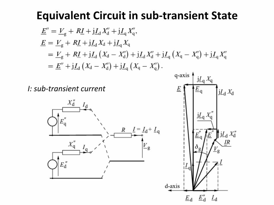
Equivalent Circuit in sub‐transient State
I: sub‐transient current

Equivalent circuit in transient state
I: transient current

Equivalent circuit in steady state
Ed = 0Eq = EfFor round rotor machine, Xd = Xq
I: steady‐state current

Determining the initial Values of the emfs.
Generator withround rotor
Generator with Salient‐pole rotor
I0: initial current

Examples
• Refer to pp. 140

Formula of Short‐circuit current under no load• Under no load, the armature current is zero. Hence,
• Since the d‐axis components are zero, the generator equivalent circuit can be simplified as shown below.
• The amplitude of the AC fault current components are given by
‘’

Formula of Short‐circuit current under no load

Formula of Short‐circuit current under no load
With subtransient saliency (i.e., Xd” ≠ Xq”), the current expression becomes
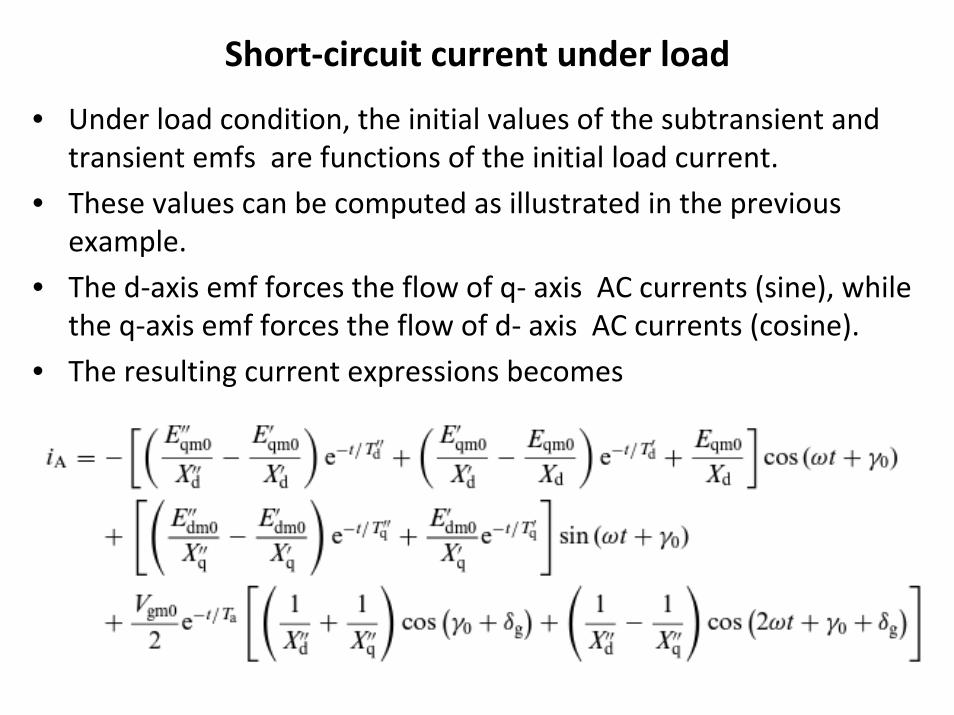
Short‐circuit current under load
• Under load condition, the initial values of the subtransient and transient emfs are functions of the initial load current.
• These values can be computed as illustrated in the previous example.
• The d‐axis emf forces the flow of q‐ axis AC currents (sine), while the q‐axis emf forces the flow of d‐ axis AC currents (cosine).
• The resulting current expressions becomes

Influence of the AVR on fault current
• Rotating exciter or static exciter fed by auxiliary source: current increases
• Static exciter fed solely from generator terminal voltage: current decays to zero.
• Compound static exciter: current settle to non‐zero value.
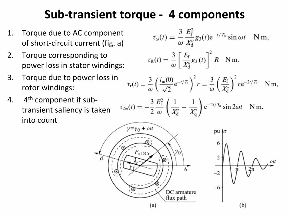
Sub‐transient torque ‐ 4 components1. Torque due to AC component
of short‐circuit current (fig. a)
2. Torque corresponding to power loss in stator windings:
3. Torque due to power loss in rotor windings:
4. 4th component if sub‐transient saliency is taken into count

Phase‐to‐phase fault (Current and flux with winding resistance neglected)

Armature mmf and impact on rotor currents (pp. 155)

Impact on sub‐transient saliency: severe distortion (pp. 157)

Impact of winding resistance (pp. 161)
where

Sub‐transient torque (pp. 162)
• Without sub‐transient saliency,
• With sub‐transient saliency,
• Unlike the case of a three‐phase fault, the torque produced during a phase‐to‐phase fault depends on the fault instant.
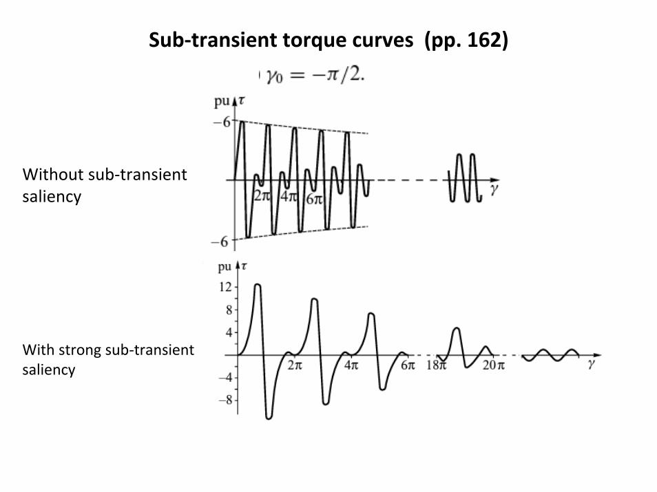
Sub‐transient torque curves (pp. 162)
Without sub‐transient saliency
With strong sub‐transient saliency

Synchronization • Ideal synchronization occurs when
• In practice, these conditions and not exactly satisfied. Hence, there will be a circulating current that contains both AC and DC components.
• For simplicity, assume a difference in voltage ΔV and ignore stator winding resistance and rotor subtransient saliency.

Torque during synchronization• Maximum values of b‐axis current component and resulting torque
(due to its DC component – not torque from AC component) :
• Maximum values of a‐axis current component and resulting torque (due to its AC and DC components) :

Torque during synchronization• Resultant torque:
• When Ef ≈ Vs, then the above expression simplifies to
• Fig (a): torque variation and Fig (b): maximum torque for different values of δ.

Short circuit in a network• Most faults occur at some distance away from the generator
terminals. When a fault occurs at F2, the transformer reactance must be added to the generator reactances:
• Secondly, the transformer resistance must be taken into account (i.e., the DC component will decay more rapidly – affects the value of Ta.). In addition,
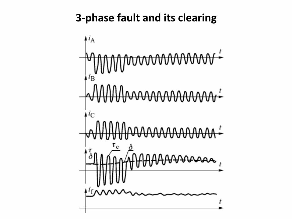
3‐phase fault and its clearing
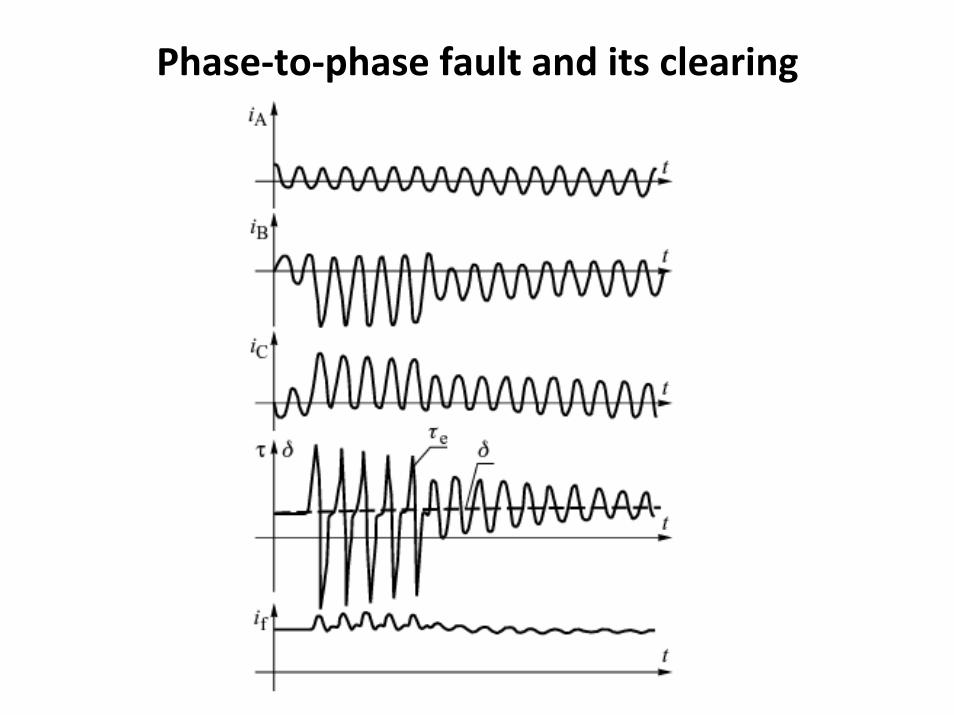
Phase‐to‐phase fault and its clearing