ee3414 multimedia communication systems – part i spring 2003
TRANSCRIPT

EE3414Multimedia Communication Systems –
Part ISpring 2003
Internet Technology
Shivendra PanwarElectrical and Computer Engineering
Polytechnic UniversityBased on the lecture note prepared by Jorg Liebeherr

Outline
The Internet– Internet protocol (IP) overview
- Addressing- IP Datagram format- Fragmentation
– ICMP (Internet Control Message Protocol)Transport layer– Overview– Flow control– Connection management
UDP vs TCPDNS

Polytechnic University
EL 536: Introduction to Com
munications N
etworks
© Jorg Liebeherr, 1998 3
History of the InternetMid 1960: Papers on “Packet Switching” emergeEnd 1969s: ARPA sponsors the development of a packet-
switching network, called the ARPANET. First four nodes are UCLA, SRI, U. Utah, UCSB
1974: The TCP/IP protocols and model are being proposed by Cerf/Kahn
1983: ARPANET adopts TCP/IP. At this time, the ARPANET has 200 routers.
1984: NSF funds a TCP/IP based backbone network. This backbone grows into the NSFNET, which becomes the successor of the ARPANET.
1995: NSF stops funding of NSFNET. The Internet is completely commercial.

Polytechnic University
EL 536: Introduction to Com
munications N
etworks
© Jorg Liebeherr, 1998 4
Main Applications of the Internet
Traditional core applications:EmailNewsRemote Login (Telnet to super computers)File Transfer
The killer application:World-Wide Web (WWW)
Future applications:Videoconferencing and TelephonyMultimedia ServicesInternet BroadcastAddressed by IPv6 and ISA in IPv4

Polytechnic University
EL 536: Introduction to Com
munications N
etworks
© Jorg Liebeherr, 1998 5
Growth of the Internet
• Latest data:Jul 98 : 36,739,000 Hosts Jan 98: 29,670,000 Hosts
Source: Network Wizards, http://www.nw.com/
Doubling every 12 month

Polytechnic University
EL 536: Introduction to Com
munications N
etworks
© Jorg Liebeherr, 1998 6
IP (Internet Protocol) is a Network Layer Protocol
IP’s current version is Version 4 (IPv4)
NetworkLayer
Link Layer
IP
ARP NetworkAccess RARP
Media
ICMP IGMP
TransportLayer
TCP UDP
NetworkLayer
Link Layer
IP
ARP NetworkAccess RARP
Media
ICMP IGMP
TransportLayer
TCP UDP
IP Protocol Stack

Polytechnic University
EL 536: Introduction to Com
munications N
etworks
© Jorg Liebeherr, 1998 7
Application
TCP
IP
NetworkAccess
Application
TCP
IP
NetworkAccess
Application protocol
TCP protocol
IP protocol IP protocol
DataLink
NetworkAccess
IP
NetworkAccess
NetworkAccess
IP
NetworkAccess
DataLink
DataLink
IP protocol
RouterRouter HostHost
Application
TCP
IP
NetworkAccess
Application
TCP
IP
NetworkAccess
Application protocol
TCP protocol
IP protocol IP protocol
DataLink
NetworkAccess
IP
NetworkAccess
NetworkAccess
IP
NetworkAccess
DataLink
DataLink
IP protocol
RouterRouter HostHost
IP Overview
IP is the highest layer protocol that is implemented at both routers and hosts:
Analogy between the transport of a datagram with the delivery of a letter: each datagram has a source and destination address, and each intermediate router forwards an entering datagram to the next intermediate router or the final host based on the destination address.

Polytechnic University
EL 536: Introduction to Com
munications N
etworks
© Jorg Liebeherr, 1998 8
IP Service
IP provides an unreliable and connectionless service (“datagram service”).– Unreliable: IP does not guarantee that a
transmitted packet will be delivered– Connectionless: Each packet (“datagram”) is
handled independently. IP is not aware that packets between hosts may be sent in a logical sequence
Consequences of an unreliable, connectionless service
– Lost Packets– Packets are delivered out-of-sequence– Duplicated Packets

Polytechnic University
EL 536: Introduction to Com
munications N
etworks
© Jorg Liebeherr, 1998 9
Internet Addresses
Each network interface on the Internet has a unique global address, called the IP addressAn IP address:
- is 32 bits long.- encodes a network number and a host number
IP addresses are written in a dotted decimal notation:128.238.42.112 means
10000000 in 1st Byte11101110 in 2nd Byte00101010 in 3rd Byte 01110000 in 4th Byte

Polytechnic University
EL 536: Introduction to Com
munications N
etworks
© Jorg Liebeherr, 1998 10
Internet Address Classes
IP distinguishes 5 classes of addresses.
1
Class A
1 1 1 0
0 network id7 bits
host24 bits
Class B 1 network id14 bits
host16 bits
0
Class C 1 network id21 bits
01 host8 bits
Class D 1 multicast group id28 bits
01 1
Class E (reserved for future use)27 bits

Polytechnic University
EL 536: Introduction to Com
munications N
etworks
© Jorg Liebeherr, 1998 11
Trade-off of Address Classes
There are a total of 232 = 4,294,967,296 IP addresses.The network numbers are assigned by InterNIC(Network Information Center).
Class A: 7 bits for netid (only 128 Class A networks)each net can have 16 million (224) hosts.
Class B:14 bits for netid (about 16,000 Class B networks)About 65,000 (216) hosts per network
Class C:21 bits for netid (about 2 million Class C networks)Only 255 hosts per network

Polytechnic University
EL 536: Introduction to Com
munications N
etworks
© Jorg Liebeherr, 1998 12
20 bytes ≤ Header Size ≤ 24 * 32 bit-words = 60 bytes20 bytes ≤ Total Length ≤ 216 bytes = 65536 bytes
IP Datagram Format
version(4 bits)
headerlength
Type of Service/TOS(8 bits)
Total Length (in bytes)(16 bits)
Identification (16 bits) flags(3 bits) Fragment Offset (13 bits)
Source IP address (32 bits)
Destination IP address (32 bits)
Options (if any, <40 bytes)
DATA
>= five 32-bit words
32-bit word0 31
TTL Time-to-Live(8 bits)
Protocol(8 bits) Header Checksum (16 bits)

Polytechnic University
EL 536: Introduction to Com
munications N
etworks
© Jorg Liebeherr, 1998 13
Fields of the IP Header
Protocol: Specifies the higher-layer protocol.Used for demultiplexing to higher layers.
Header checksum: verifies correctness of header.– 16 bit ones complement addition of all 16-bit words in the header,
verified and recomputed at each router
IP
ICMP IGMP
TCP UDP
Application

Polytechnic University
EL 536: Introduction to Com
munications N
etworks
© Jorg Liebeherr, 1998 14
IP Fragmentation
FDDIRing
RouterHost A Host B
Ethernet
• Host A sends a large IP datagram to Host B.
• Any Problem with that?
MTUs: FDDI: 4352 Ethernet: 1500
• IP router splits the datagram into several datagrams (=Fragmentation)

Polytechnic University
EL 536: Introduction to Com
munications N
etworks
© Jorg Liebeherr, 1998 15
What’s involved in Fragmentation?
The following fields in the IP header are involved:version(4 bits)
headerlength
Type of Service/TOS Total Length (in bytes)
Identification flags Fragment Offset
......
TTL Time-to-Live(8 bits)
Protocol(8 bits) Header Checksum (16 bits)
Identification is the same in all fragments.Flags contains a “more fragments” bit
(There is also a “don’t fragment bit” that can be set)Fragment offset contains the offset of current fragment
in the original datagramTotal length is changed by fragmentation

Polytechnic University
EL 536: Introduction to Com
munications N
etworks
© Jorg Liebeherr, 1998 16
Type(8 bits)
Code(8 bits)
Checksum(16 bits)
(additional information dependent on Type and Code)
32-bit word0 31
ICMP
The Internet Control Message Protocol (ICMP) is the protocol used for error and control messages in the Internet ICMP provides an error reporting mechanism of routers to the sourcesAll ICMP packets are encapsulated as IP datagramsThe packet format is simple:

Polytechnic University
EL 536: Introduction to Com
munications N
etworks
© Jorg Liebeherr, 1998 17
Types of ICMP Packets
Many ICMP packet types exist, each with its own format.A Selection:
Type Field: Message Type:0 Echo Reply3 Destination Unreachable4 Source Quench5 Redirect (Change Route)8 Echo Request11 Time Exceeded12 Parameter Problem in Datagram14 Timestamp Request

Polytechnic University
EL 536: Introduction to Com
munications N
etworks
© Jorg Liebeherr, 1998 18
ICMP Message Types
ICMP messages are either query messages or errormessages. ICMP query messages:
- Echo request / Echo reply- Router advertisement / Router solicitation- Timestamp request / Timestamp reply- Address mask request / Address mask reply
ICMP error messages:- Host unreachable- Source quench- Time Exceeded - Parameter Problem

Polytechnic University
EL 536: Introduction to Com
munications N
etworks
© Jorg Liebeherr, 1998 19
The PING program
PING (=Packet IntetNet Groper) is a program that utilizes the ICMP echo request and echo reply messages
PING is used to verify if a certain host is up and running. It is used extensively for fault isolation in IP networks

Polytechnic University
EL 536: Introduction to Com
munications N
etworks
© Jorg Liebeherr, 1998 20
PING’s are handled directly by the kernel.Each Ping is translated into an ICMP Echo RequestThe Ping’ed host responds with an ICMP Echo Reply
Echo Request and Reply
AIDAAIDA
ICMP ECHO REQUEST
MNG MNG
ICMP ECH
O REPLY

Transport Layer Outline
Transport layer functionality overviewAddressingFlow control
– Credit allocationError controlConnection management
– Initiating and terminating connectionsExamples: TCP, UDP
– Overview of TCP vs. UDP– TCP flow control and error control
Yao Wang EL536 --- Data and Computer Communications

Polytechnic University
EL 536: Introduction to Com
munications N
etworks
© Jorg Liebeherr, 1998 22
Overview of Transport Layer• Transport layer protocols are end-to-end protocols • Transport layer is only implemented at the hosts• Session and presentation layer may not be implemented, most application layer protocols simply open a TCP/UDP connection
Application
Transport
Network
HOST
Data Link Data Link Data Link
Network
Application
Transport
Network
HOST
Data Link

Polytechnic University
EL 536: Introduction to Com
munications N
etworks
© Jorg Liebeherr, 1998 23
Protocol Mechanisms
AddressingMultiplexing Flow ControlError ControlConnection Management
Note: The mechanisms needed to implement a transport service are largely dependent on the existing network layer service

Polytechnic University
EL 536: Introduction to Com
munications N
etworks
© Jorg Liebeherr, 1998 24
Addressing
An address at the transport layer is typically a tuple (Station, Port) where – Station is the network address of the host, and– Port identifies the application
Recall: The <IP address, port number> tuples used in the Unix assignments are in fact transport layer addresses
Problem with Addressing: How to find the address of a service?

Polytechnic University
EL 536: Introduction to Com
munications N
etworks
© Jorg Liebeherr, 1998 25
Flow Control
Why do we need flow control at the transport layer? 1. User of receiving transport entity cannot keep up
with the data flow.2. Receiving transport entity itself cannot keep up
with flow of incoming packet.
Result: Buffer overflows in the receiving transport entity.

Polytechnic University
EL 536: Introduction to Com
munications N
etworks
© Jorg Liebeherr, 1998 26
Need for Flow Control
transportentitity
transportentitity
Site A Site B
networklayer
transportuser
transportlayer

Polytechnic University
EL 536: Introduction to Com
munications N
etworks
© Jorg Liebeherr, 1998 27
Flow Control at the Transport Layer
Flow Control at the transport layer is more complex than flow control at the data link layer:– Delays are variable and are longer– Flow control involves the transport users, the
transport entities, and the network service

Approaches to Flow Control
Do Nothing– TPDUs that overflow the buffer are discarded– May be appropriate for delay sensitive but loss insensitive
services (e.g. audio-visual conferences)Refuse to accept TPDUs from the network layer
– Requires a backpressure mechanism that pushes flow control to the network layer
(Fixed) Sliding-window Protocol– Problems of fixed:
- Withholding acknowledgments in an unreliable network results inretransmission
- Sliding window flow control not effective– Solution:
- separate acknowledgement from flow control – credit allocation- Adapt window size
Yao Wang EL536 --- Data and Computer Communications

Polytechnic University
EL 536: Introduction to Com
munications N
etworks
© Jorg Liebeherr, 1998 29
Credit Allocation Flow Control
Credit Allocation Flow Control is an extension of the sliding window flow control.Main Idea:– Enhance the sliding window protocol by a
mechanism that decouples acknowledgments from flow control.
Then:– Packets can be acknowledged without granting
permission for new transmissions– Used in many existing transport protocols,
including TCP

Polytechnic University
EL 536: Introduction to Com
munications N
etworks
© Jorg Liebeherr, 1998 30
Credit Allocation Flow Control
Initialization during connection setup: – Set initial window size of receiver– Receiver both acknowledges TPDUs and grants
credit by sending a message:(ACK N, CREDIT M)
– ACK N: Acknowledges all sequence numbers through N-1
– CREDIT M: Sets the number of credits to MCredit is the maximum window size (=window size that can be allocated at
the sender for this connection)

Polytechnic University
EL 536: Introduction to Com
munications N
etworks
© Jorg Liebeherr, 1998 31
Example
ReceiverTransmitter
0 1 2 3 4 5 6 7 0 1 2 3 0 1 2 3 4 5 6 7 0 1 2 3
0 1 2 3 4 5 6 7 0 1 2 3 0 1 2 3 4 5 6 7 0 1 2 3
0 1 2 3 4 5 6 7 0 1 2 3
0 1 2 3 4 5 6 7 0 1 2 3
T0T1T2
ACK2, Credit 6
0 1 2 3 4 5 6 7 0 1 2 3
T4T5
0 1 2 3 4 5 6 7 0 1 2 3
Initial Setting: Credit = 7
Fig. 17.5 in text
T3 T4
ACK3, Credit 5

Polytechnic University
EL 536: Introduction to Com
munications N
etworks
© Jorg Liebeherr, 1998 32
Example (cnt’d)
ReceiverTransmitter
0 1 2 3 4 5 6 7 0 1 2 3 0 1 2 3 4 5 6 7 0 1 2 3
0 1 2 3 4 5 6 7 0 1 2 3 0 1 2 3 4 5 6 7 0 1 2 3
0 1 2 3 4 5 6 7 0 1 2 3
D5D6D7
ACK0, Credit 4
0 1 2 3 4 5 6 7 0 1 2 3

Polytechnic University
EL 536: Introduction to Com
munications N
etworks
© Jorg Liebeherr, 1998 33
Connection Management
Connection establishment and connection termination are essential for a connection-oriented service
Connection establishment is asymmetric:– one side puts itself in a LISTEN state (server)– one side issues a request for connection or RFC
(client)– One connection is established, data flow is full
duplex in both directions

Polytechnic University
EL 536: Introduction to Com
munications N
etworks
© Jorg Liebeherr, 1998 34
Simple Solution (which has problems)
CR (SeqNo = x) Connection Request, A wants to start with SeqNo = xACK (SeqNo = y) Acknowledge request, B will wants to start with SeqNo = yDATA (SeqNo = x)Data transmission with SeqNo x
Host A Host B
CR (SeqNo = x)
ACK (SeqNo = y)
DATA(SeqNo = x)
Two Way Handshake

Polytechnic University
EL 536: Introduction to Com
munications N
etworks
© Jorg Liebeherr, 1998 35
Problems with Two-Way Handshake
B responds toCR(SeqNo = z),an old duplicate connection requests from A In the shown sce-nario, A believes that the ACK is for the connection request CR(SeqNo = y)
Host A Host B
CR (SeqNo = x)
ACK (SeqNo = y)
DATA(SeqNo = x)
CR (SeqNo = z)
Result: A starts to send data with Sequence x. B will throw the data away since it expects SeqNo = z

Polytechnic University
EL 536: Introduction to Com
munications N
etworks
© Jorg Liebeherr, 1998 36
Three-Way Handshake
Note: A and B acknowledge the sequence number from the other side
This solution provides protection from old duplicate connection requests
Host A Host B
CR (SeqNo = x)
ACK (SeqNo = y, ACK = x)
DATA(SeqNo = x, ACK = y)

Polytechnic University
EL 536: Introduction to Com
munications N
etworks
© Jorg Liebeherr, 1998 37
Connection Termination
A connection release should involve both sides of the connection (otherwise data is lost)
CR ()
ACK ()
DATA()DATA()DATA()DATA()
DR ()
Host A Host B
Here: B should wait after Disconnection Request (DR) is sent until all data has arrived

Polytechnic University
EL 536: Introduction to Com
munications N
etworks
© Jorg Liebeherr, 1998 38
Connection Termination in 4 steps (TCP)
An elegant way to terminate connections is to have each end shut down independently (“half-close”)If one end wants to shut down, it sends a DR messageFour steps involved:
(1) A sends a DR to B (active close)(2) B ACKs the DR, (completing half-close)(at this time: B can still send data to A)
(3) After certain time, B sends a DR to A (passive close)(4) A ACKs the DR (completing full-close)

Polytechnic University
EL 536: Introduction to Com
munications N
etworks
© Jorg Liebeherr, 1998 39
Transport Protocols in the Internet
The Internet uses two transport protocols
– Transmission Control Protocol (TCP)
– User Datagram protocol (UDP)

Polytechnic University
EL 536: Introduction to Com
munications N
etworks
© Jorg Liebeherr, 1998 40
Transport Protocols in the Internet
ApplicationLayer
NetworkLayer
Link Layer
IP
ARP HardwareInterface RARP
Media
ICMP IGMP
TransportLayer
TCP UDP
UserProcess
UserProcess
UserProcess
UserProcess

Polytechnic University
EL 536: Introduction to Com
munications N
etworks
© Jorg Liebeherr, 1998 41
Transport Protocols in the Internet
UDP UDP -- User Datagram User Datagram ProtocolProtocol
datagram orientedUnreliable (best-effort), connectionlesssimpleunicast and multicastLow-delay, hence good for multimedia applicationsused a lot for services
– network management (SNMP), routing (RIP), naming (DNS), etc.
TCP - Transmission Control Protocol
stream oriented, in sequencereliable, connection-orientedcomplexonly unicastused for most Internet applications:
– web (http), email (smtp), file transfer (ftp), terminal (telnet), etc.

Polytechnic University
EL 536: Introduction to Com
munications N
etworks
© Jorg Liebeherr, 1998 42
UDP - User Datagram Protocol
UDP is supports unreliable transmissions of datagramsUDP merely extends the host-to-to-host delivery service of IP datagram to an application-to-application serviceThe only thing that UDP adds is multiplexing and demultiplexing (encaptulation)
UDP
IP IPIP IP IP
UDP
Applications Applications

Polytechnic University
EL 536: Introduction to Com
munications N
etworks
© Jorg Liebeherr, 1998 43
UDP Format
IP header UDP header UDP data
UDP message length Checksum
DATA
20 bytes 8 bytes
0 15 16 31
Source Port Number Destination Port Number
•Port numbers identify sending and receiving applications (processes). Maximum port number is 216-1= 65,535• Message Length is at least 8 bytes (I.e., Data field can be empty) and at most 65,535• Checksum is for header (of UDP and some of the IP header fields)

Polytechnic University
EL 536: Introduction to Com
munications N
etworks
© Jorg Liebeherr, 1998 44
Port Numbers
UDP (and TCP) use port numbers to identify applicationsA globally unique address at the transport layer (for both UDP and TCP) is a tuple <IP address, port number>There are 65,535 UDP ports per host
IP
TCP UDP
UserProcess
Demultiplexbased on
Protocol field in IPheader
UserProcess
UserProcess
UserProcess
UserProcess
UserProcess
Demultiplexbased on
port number

Polytechnic University
EL 536: Introduction to Com
munications N
etworks
© Jorg Liebeherr, 1998 45
TCP
TCP = Transmission Control ProtocolConnection-oriented protocolProvides a reliable unicast end-to-end byte stream over an unreliable internetwork.
TCP
IP Internetwork
Byte
Stre
am
Byte
Stre
am
TCP
Polytechnic University
EL 536: Introduction to Com
munications N
etworks
© Jorg Liebeherr, 1998 46
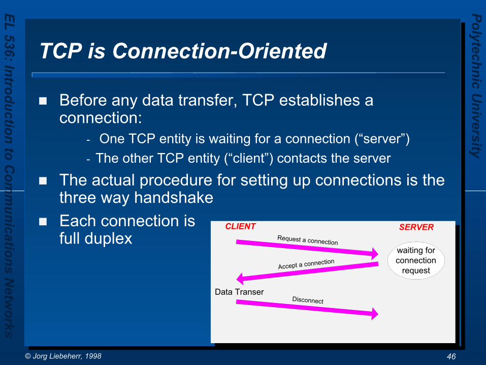
TCP is Connection-Oriented
Before any data transfer, TCP establishes a connection:
- One TCP entity is waiting for a connection (“server”)- The other TCP entity (“client”) contacts the server
The actual procedure for setting up connections is the three way handshakeEach connection is full duplex
CLIENT SERVER
waiting forconnection
request
Request a connection
Accept a connection
DisconnectData Transer

Polytechnic University
EL 536: Introduction to Com
munications N
etworks
© Jorg Liebeherr, 1998 47
Reliable Data Transfer
Byte stream is broken up into chunks which are called segments– Receiver sends acknowledgements (ACKs) for
segments– TCP maintains a timer. If an ACK is not received
in time, the segment is retransmitted
Detecting errors:– TCP has checksums for header and data.
Segments with invalid checksums are discarded– Each byte that is transmitted has a sequence
number

Polytechnic University
EL 536: Introduction to Com
munications N
etworks
© Jorg Liebeherr, 1998 48
TCP Segment Format
IP header TCP header TCP data
Sequence number (32 bits)
DATA
20 bytes 20 bytes
0 15 16 31
Source Port Number Destination Port Number
Acknowledgement number (32 bits)
window sizeheaderlength 0 Flags
Options (if any)
TCP checksum urgent pointer
20 bytes
• TCP segments have a 20 byte header with >= 0 bytes of data.

Polytechnic University
EL 536: Introduction to Com
munications N
etworks
© Jorg Liebeherr, 1998 49
Flow Control in TCP
Flow Control: – How to prevent that the sender overruns the
receiver with information?Flow Control in TCP– TCP implements sliding window flow control– Sending acknowledgements is separated from
setting the window size at sender. Acknowledgements do not automatically increase the window size (credit allocation flow control)
– Acknowledgements are cumulativeHow to determine window size adaptively?

Polytechnic University
EL 536: Introduction to Com
munications N
etworks
© Jorg Liebeherr, 1998 50
Slow Start/Congestion Avoidance
TCP has a mechanism for congestion control. The mechanism is implemented at the sender
The sender has two additional parameters:– Congestion Window (cwnd; Initial value is 1 MSS counted
as bytes) (For flow control)– SlowStartThreshhold (ssthresh; Initial value is 65536
bytes) (For congestion avoidance)The receiver tells the sender the flow control window (=credit in the ACK) sizeThe window size at the sender is set as follows:Allowed Window =
MIN (flow control window, congestion window)congestion window: flow control by the senderflow-control window (credit): flow control by the receiver

PC (web client)
DNS Server
eeweb server
128.238.37
.15
.3
.40a:11:23:45:0c:de
1b:3d:23:75:9c:a7
12:23:34:6f:1a:30
• PC web client, DNS server and eeweb server are all on the same ethernet LAN and same IP subnet.
• PC client has the IP address of the DNS server ethernet card, but it does not have the MAC address
ARP (128.238.37.3)
DNS query/UDP/IP(eeweb.poly.edu)
ARP reply (12:23:34:6f:1a:30)
DNS reply(128.238.37.4)
ARP(128.238.37.4)
ARP reply(1b:3d:23:75:9c:a7)
Http/tcp/ip/ethernet(src. IP address: 128.238.37.15dst. IP address: 128.238.37.4src. MAC address: 0a:11:23:45:0c:dedst. MAC address: 1b:3d:23:75:9c:a7)
Domain Name Server Illustration

Summary
Transport layer functions– Addressing: host address + port (process)– Connection management: establishment and termination– Flow control: sliding window with credit allocation – Error control: retransmission with adaptive timeout
Necessary transport layer protocols depend on the underlying network layer
– If the network layer provides connection-oriented, reliable service, then transport control is easy
- Ex. X.25, ATM, Ethernet– Otherwise, providing reliable transport is more complicated
- Ex. Internet

Summary (Cnt’d)
Transport protocols in IP networks – IP is a connectionless, unreliable network– UDP provides connectionless, unreliable service, merely adds the
port number and checksum header to the IP layer– TCP provides connection-oriented, reliable service
- Connection management: – 3 way handshake for open, – 4 step for close.
- Congestion control: sender window adapts to congestion status (slow start with congestion avoidance)
- Error control using retransmission: – Retransmission time out (RTO) based on smoothed RTT
measurements– Exponential backoff (doubling RTO) after timeout