effect of fiber flocculation and filling design on … · peer-reviewed article...
TRANSCRIPT

PEER-REVIEWED ARTICLE ncsu.edu/bioresources
El-Sharkawy et al. (2008). “Refiner loadability and filling,” BioResources 3(2), 403-424 403
EFFECT OF FIBER FLOCCULATION AND FILLING DESIGN ON REFINER LOADABILITY AND REFINING CHARACTERISTICS
Khalil El-Sharkawya*, Sanna Haavistob, Kari Koskenhelya and Hannu Paulapuroa
The loadability of a pulp refiner was studied using refiner data such as gap movement, total power, no-load power, and net refining power. Two different types of pulp and three different types of refiner filling were used in the study. The floc formation and floc size of each pulp was studied in a flow channel simulating filling grooves. The loadability of the pulp refiner was linked to refining effects such as fiber shortening, and internal and external fibrillation. The trapping point of the refiner, and therefore refiner loadability, was found to be more related to fiber characteristics such as fiber length and coarseness, while being less dependent on refining consistency in the range of 2.0-5.5%. The data on the formation of flocs and floc size was used to explain the trapping of fibers between refiner bars and the refiner gap width. Filling design characteristics such as groove width and cutting speed affect the gap width and trapping of flocs inside the refiner. Fillings with high cutting speed tend to break flocs composed of long and short fibers at the same rate and therefore both types of floc maintain the same gap width. On the other hand, wide-groove fillings with lower cutting speed have a gentler effect and the differences in fiber characteristics are easily reflected in the gap width and trapping point. Fillings with low cutting speed have a greater straightening effect than fiber cutting, whereas narrow-bar fillings have a more noticeable effect on fiber cutting, external fibrillation, and fiber swelling.
Keywords: Refiner; Flocculation; Filling design; Swelling; External fibrillation Contact information: a: Helsinki University of Technology, Department of Forest Products Technology, Paper and Printing Technology Research and Education group, P.O. Box 3320, FIN -02015 HUT - Finland; b: VTT Technical Research Center of Finland, P.O. Box 1603, 40101 Jyväskylä -Finland; *Corresponding author: [email protected] INTRODUCTION Pulp refining is an important step in developing papermaking fibers to their final quality level. Despite the complexity of the pulp refining process, a number of refining effects have been identified and characterized by many authors, including Higgins and de Yong (1961), Giertz (1980), Ebeling (1980), and Page (1989). Primary refining effects consist of the structural changes associated with refining, distinguishing beaten fibers from unbeaten fibers, i.e., internal fibrillation (swelling), external fibrillation, fines formation, fiber cutting or shortening, and fiber curling or straightening. Internal fibrillation or swelling is related to the breakage of internal bonds between microfibrils due to mechanical action, causing the pore structure inside the cell wall to expand and to hold more water (Stone et al. 1968, Maloney and Paulapuro 1999). This effect is reflected as an increase in the fiber’s specific volume, specific surface, and

PEER-REVIEWED ARTICLE ncsu.edu/bioresources
El-Sharkawy et al. (2008). “Refiner loadability and filling,” BioResources 3(2), 403-424 404
flexibility. Recently, Kerekes and Senger (2006) considered three effective types of strains in refining: compression, tension, and shear. Compression and bending strains create tensile, axial compressive, and shear stresses in fibers, which break bonds between microfibrils and likely cause internal fibrillation. External fibrillation is defined as the peeling off of fibrils from the fiber surface, while fibrils are still attached to the main body of fibers (Page 1989). External fibrillation is reflected as an increase in the fiber’s surface area and swollen specific volume, and in the fiber flow and drainage resistance. The surface shear strain inside the refiner is likely to be the main cause of external fibrillation. Formation of fines is similar to external fibrillation, which is created by the surface shear strains inside the refiner, but the fibrils created are completely detached from the body of fibers. Fines have a decisive effect on the specific fiber surface area and the increase in drainage resistance. Fiber straightening is likely to originate from the tension strain inside the refiner, which mainly tends to straighten fibers and reduce fiber curl. The behavior of the refiner gap during refining has been a subject of interest for many researchers (Range 1951; Steenberg 1951; Page et al. 1962; Fox et al. 1979), concluding that the refiner gap is related to fiber characteristics and pulp flows as floc inside the refiner grooves. In 1990, Hietanen and Ebeling proposed a floc refining hypothesis, which entails an increase in the refiner gap as flocculation increases. Lately, using single bar refiner, the forces and force distribution among fibers were used to characterize the refining action (Martinez and Kerekes 1994; Martinez et al. 1997; Batchelor et al. 2001).
Papermaking fibers tend to agglomerate and form flocs by mechanical or chemical mechanisms. At low shear or decaying turbulence the fibers tend to build up and form flocs, and at high turbulence and high shear, the fiber flocs are dispersed and broken up. Floc formation, floc dispersion, and floc size measurements has been studied by several researchers (Steen 1989; Stoere et al. 2001; Switzer et al. 2003; Salmela et al. 2005). Accordingly, there are still open questions, such as the floc scale, the fiber scale, and how these scales are linked to the uniformity of the force distribution inside the refiner, and the effect of filling dimensions (bar width, groove width and edge form) on fiber pad picking and the capture of fibers between rotor and stator. The present study was conducted to find the link between refiner loadability and floc size for different filling designs and to determine how this is reflected in different refining effects, such as internal fibrillation, external fibrillation, and fiber shortening. EXPERIMENTAL Materials Two different pulps were used in the study. Their fiber characteristics are shown in Table 1. Pulp 1 was a mixture of hardwood and softwood (50:50) by weight, and pulp 2 was a 100% softwood pulp. The softwood pulp used was a once-dried softwood kraft pulp obtained from a Finnish pulp mill producing ECF-bleached pulp. The pulp had a length-weighted average fibre length of 2.50 mm and a freeness level of 720 mL. The pulp contained 61% pine and 39% spruce. The hardwood pulp used was a once-dried

PEER-REVIEWED ARTICLE ncsu.edu/bioresources
El-Sharkawy et al. (2008). “Refiner loadability and filling,” BioResources 3(2), 403-424 405
market birch pulp obtained from a Finnish pulp mill. The pulp was produced by ECF bleaching and had a length-weighted average fiber length of 0.830 mm, a freeness level of 580 mL, and a brightness of 90% ISO. The crowding number was calculated according to formula 1 proposed by Kerekes et al. (1985),
w
LCN m
25= (1)
where Cm is the mass consistency, L is the average fiber length, and w is the fiber coarseness. Table 1. Pulp Types Used
Sample
Lav (mm)
Width (μm)
Coarseness
(mg/m)
*Crowding
number
Pulp 1
1.75
20.30
0.127
240
Pulp 2
2.50
25.35
0.189
330 * Crowding number was calculated using equation number 1 and the pulp consistency of 2%.
Refining The refining trials were conducted with a Voith LR 40 laboratory refiner at the Department of Forest Products Technology of the Helsinki University of Technology. The specific edge load theory (Brecht and Siewert 1966) was applied to control the refining trials. Three different refiner fillings were used in refining. The first is a typical conical filling commonly used for softwood refining, the second a wide-bar disc filling and the third a narrow-bar disc filling commonly used for hardwood refining. The specifications of the fillings used are shown in Table 2. The refining was carried out at the same conditions of 2000 rpm, a refining energy input of 50 kWh/t, and a specific edge load of 2.0 J/m. The data collected from the refiner included the no-load power, total power, and the stator movement as an indication of refiner gap movement. The no-load power was measured before actual refining using water. The total power was recorded and monitored during refining. The gap movement recorded from the movement of the stator was used to describe the stator movement and the change in the gap between the rotor and stator during refining. As the stator moves towards the rotor, the gap closes, and the bigger the movement of the stator, the smaller the gap. Net power was calculated from the total power and no-load power. To estimate refiner loadability and the trapping point at which the fibers start to be picked up by the rotor and stator bars, and, accordingly, the power consumed in actual refining, a technique similar to the one proposed by Batchelor et al. (2006) was used.
At each refining point, fiber length, fiber width, fiber coarseness, fines content, and fibrillation percentage were measured using the Kajaani FibreLab analyzer (Richardson et al. 2003; Turunen et al. 2005). Pulp freeness (mL) was measured with a CSF tester. The fiber saturation point (FSP) was measured using the solute exclusion

PEER-REVIEWED ARTICLE ncsu.edu/bioresources
El-Sharkawy et al. (2008). “Refiner loadability and filling,” BioResources 3(2), 403-424 406
technique (Stone and Scallan 1968) and used as a measure of internal fibrillation or swelling. Table 2. Fillings Used in Refining Filling CEL (km/s) Bar height
(mm) Bar width
(mm) Groove
width (mm) Bar angle (o)
Conical filling 0.67 3.0 3.6 8-12 30
Wide-bar disc filling
1.067 3.0 3.6 4.4 30
Narrow-bar disc filling
2.84 2.0 2.0 3.0 30
Floc Size Measurements
The flocculation of the pulps was studied in a flow loop system simulating the flow through refiner grooves and the flow velocity in normal refining. The loop consisted of a 0.2m3 tank, a centrifugal pump, and a plastic flow loop with an inner diameter of 40mm and slit height of 5 mm (refiner groove width). The flow geometry and measure-ment set-up are presented in Fig. 1. The flow conditions used in the measurements are shown in Table 3. The flocculation of pulps was studied using an image analysis technique. The average size of flocs was evaluated downstream after the abrupt contraction from 40 mm through the slit of 5 mm using a fast CCD camera mounted above the tube. A computer program was used to adjust the flow speed, light source, and position of the camera. A total of 200 images per position along the slit were taken. After correcting the images for uneven illumination, the floc size was determined in the flow direction (FD) and the transverse flow direction (TD) as a run-length average of the median thresholded image. The analysis method is described in detail by Kellomäki and Karema (1999), Karema and Salmela (2001), and Salmela and Kataja (2005). The method enables fast and accurate measurement of floc size through the slit, under conditions resembling the flow inside the filling grooves. The experiments were done for both pulps 1 and 2 at a consistency of 2%, using three different flow rates. Before the measurements, the flow loop was kept circulating for at least 30 minutes to ensure good homogenizing of the pulp. As the flow rate was increased from 1.5 to 2.5 l/s, the average flow speed in the slit was changed from 7.5 to 12.5 m/s. In addition to determining average floc size in flow direction and cross-direction, the aspect ratio and mean floc area reduction were calculated. The aspect ratio is defined as the average floc size in the FD direction divided by the floc size in TD direction. The mean floc area reduction is defined as the percentage cross-section area reduction for elliptically shaped fiber flocs,
⎟⎟⎟
⎠
⎞
⎜⎜⎜
⎝
⎛
⋅⋅
⋅⋅−=
004
41TDFD
TDFDA
π
π (2)

PEER-REVIEWED ARTICLE ncsu.edu/bioresources
El-Sharkawy et al. (2008). “Refiner loadability and filling,” BioResources 3(2), 403-424 407
where, FD0 and TD0 are the average floc sizes at the beginning of the slit, and FD and TD are the average floc sizes at the end of the slit.
Fig. 1. Flow geometry used in measurements. The tube section and slit dimensions (height and length) were used to simulate refiner grooves.
Table 3. Flow Conditions Used in Floc Size Measurements
Average flow rate
Average flow velocity
Reynolds number
1.5 l/s 7.5 m/s 37500
2.0 l/s 10 m/s 50000
2.5 l/s 12.5 m/s 62500
RESULTS Analysis of Refining Data Using the data collected from the refiner, a total power-gap movement curve was designed for the analysis, as shown in Fig. 2. Total power is the total power consumed during the whole refining, from the point when the stator moves towards the rotor and the gap starts to close. The total power includes both the refining power actually consumed in refining and hydrodynamic power consumed in circulating the pulp through the refiner. Therefore, the total power seen in Fig. 2 could be divided into two parts: no-load power and net power. The no-load power is the power consumed during the closing of the gap (stator moves towards rotor) without any significant increase in the total power consumption.

PEER-REVIEWED ARTICLE ncsu.edu/bioresources
El-Sharkawy et al. (2008). “Refiner loadability and filling,” BioResources 3(2), 403-424 408
This power covers most of the mechanical losses, hydraulic losses due to friction and pumping losses. Therefore, the no-load power is represented by the linear part of the curve. Figure 3 shows the linear fit for the linear part of the curve, making it possible to estimate correctly the no-load power based on stock rather than water. Previous studies (Arjas 1970; Rihas 1995; Westman 1985) have linked the no-load power to mechanical defects of the refiner, such as wear problems, mechanical losses, and electrical losses in the refiner motor. As the trials were done in similar refining conditions and with the same sequences, differences in no-load power were not expected between different pulp refining trials. The point at which the refiner starts to consume power due to refining action is the point where the curves in Fig. 2 start to move from a linear into an exponential function. The end of the linear part of the curve is defined as the point at which the total power is 1% higher than the no-load power shown in Fig. 3. Accordingly, the net power was obtained by subtracting the fitted no-load power shown in Fig. 3 from the total power in Fig. 2. This calculation makes it possible to express the net power as a function of the gap closure, as seen in Fig. 4. The trapping point (net power starts to be consumed) or the loadability of the refiner is a filling-characteristic value, which is also dependent on the type of fiber used in refining as well as the refining conditions. As shown in Fig. 4, when pulp 2 was refined with conical fillings at a refining energy level of 50 kWh/t and a SEL of 2 J/m, the fibers started to be trapped at a stator movement (gap position) of 19,000 μm, with the final gap position at full energy input being about 21,500 μm.
0
0.5
1
1.5
2
2.5
3
0 4000 8000 12000 16000 20000
Stator movement (Gap position),μm
Total P
ower
Pulp 2 ‐SEL 2.0, SRE 50kWh/t
Fig. 2. Refiner total power as a function of stator movement (gap closure) for pulp 2 refined with conical fillings at SEL 2.0 J/m and SRE 50 kWh/t.

PEER-REVIEWED ARTICLE ncsu.edu/bioresources
El-Sharkawy et al. (2008). “Refiner loadability and filling,” BioResources 3(2), 403-424 409
y = 2E‐05x + 1,5137
R2 = 0,9183
0
0.5
1
1.5
2
2.5
3
8000 10000 12000 14000 16000 18000 20000
Stator movement (Gap Posistion),μm
Total P
ower
Pulp 2 ‐ SEL 2.0, SRE 50kWh/t
No‐Load Power
Fig. 3. Refiner no-load power as a function the stator movement (gap closure). The solid line indicates the linear part of the power curve.
y = 9E‐18e0,0018x
R2 = 0,9763
0
0.2
0.4
0.6
0.8
1
1.2
18000 18500 19000 19500 20000 20500 21000 21500
Stator movement (Gap position) , μm
Net
Pow
er (T
otalPo
wer
‐ No load
Pow
er)
Pulp 2, SEL 2.0, SRE 50kWh/t
Fig. 4. Net power as a function of stator movement (gap closure) in refining with conical fillings.

PEER-REVIEWED ARTICLE ncsu.edu/bioresources
El-Sharkawy et al. (2008). “Refiner loadability and filling,” BioResources 3(2), 403-424 410
Role of filling design In this study, three different fillings were used, as shown in Table 2. The main differences between the fillings were in groove width, bar width, and bar height. The fillings dimensions were reflected as differences in cutting speed, with narrow-bar fillings having the highest cutting speed of 2.84 km/s and conical fillings the lowest of 0.67 km/s. Figure 5 shows the net power in refining pulps 1 and 2 under the same refining conditions using conical fillings. Pulp 2, having long and coarse fibers, was trapped early in gap closure. This is attributed to the big and strong flocs formed by these fibers, which maintain a wide gap and are trapped early between rotor and stator bars. On the other hand, pulp 1, having slightly shorter and thinner fibers, was trapped later, maintaining a smaller gap width compared to pulp 2. Similar differences have been noticed when using wide-bar disc fillings, as shown in Fig. 6. This confirms that a pulp that forms bigger and stronger flocs is trapped earlier and maintains a wider gap than a pulp that forms small and weak flocs. Both conical and wide-bar disc fillings have a relatively low cutting speed, and the shear needed to disperse and break flocs is probably relatively low. The behavior was totally different when refining the pulps with narrow-bar disc fillings and high cutting edge speed (more than 4 times the cutting speed of conical fillings), as shown in Fig. 7. In this case, both pulps tended to collapse to almost the same curve, with the same trapping point and gap width (stator movement). It seems that the narrow-bar disc fillings with narrow groves and high cutting edge speed create a high shear field inside the refiner which disperses and breaks fibers flocs in the refining zone. Therefore, the big floc size formed with long and coarse fibers does not cause big differences in the gap width, trapping point or loadability of the refiner, and both pulps behave in a similar way because of the special characteristics and design of narrow-bar disc fillings.
y = 9E‐18e0,0018x
R2 = 0,9763
y = 2E‐33e0,0035x
R2 = 0,9775
0
0.2
0.4
0.6
0.8
1
1.2
18000 18500 19000 19500 20000 20500 21000 21500
Stator movement (Gap position) , μm
Net
Pow
er (T
otalPo
wer
‐ No load
Pow
er)
Pulp 2, SEL 2.0, SRE 50kWh/t
Pulp 1, SEL2.0, SRE 50 kWh/t
Fig. 5. Net power as a function of stator movement (gap closure) in refining with conical fillings.

PEER-REVIEWED ARTICLE ncsu.edu/bioresources
El-Sharkawy et al. (2008). “Refiner loadability and filling,” BioResources 3(2), 403-424 411
Using the same pulp it was possible to compare two different fillings, for example wide-bar disc fillings and narrow-bar disc fillings, as shown in Fig. 8. For a certain pulp, both fillings had the same trapping point, as the trapping point is more related to pulp characteristics. In reaching the same level of net refining energy of 50kWh/t, the wide-bar disc fillings maintained a wider gap than the narrow-bar disc fillings, and the net power for narrow-bar disc fillings was almost three times the net power for wide-bar disc fillings. This could be explained by the high cutting speed of the narrow-bar disc fillings, which tend to break more flocs and cut more fibers than wide-bar disc fillings, which have a much lower cutting edge speed. Therefore, for the same pulp, filling dimensions (bar width, groove width, and cutting speed) have a strong effect on the gap size and the total net power consumed in refining.
0.0000
0.2000
0.4000
0.6000
0.8000
1.0000
1.2000
1.4000
1.6000
1.8000
2.0000
16500 16700 16900 17100 17300 17500 17700
Stator movement (Gap position) , μm
Net
Pow
er
Pulp 1 ‐ SEL 2.0, SRE 50kW, wide di s c fi l l i ng
Pulp 2 ‐ SEL 2.0, SRE 50kW, wide di s c fi l l i ng
Fig. 6. Net power as a function of stator movement (gap closure) in refining with wide-bar disc fillings. Role of pulp characteristics The main pulp characteristics that affect pulp refining are pulp consistency and pulp fiber properties (length, width, coarseness). Those parameters and their effects on refiner loadability (trapping point) and gap width were studied. Figure 9 shows the relationship between net power and stator movement (gap width) for pulp 1 at a constant consistency of 4% when the fiber characteristics were changed by adding 30% and 60% by weight of pulp 2. Increased addition of pulp 2 caused an increase in the average fiber length and in the percentage of long and coarse fibers, which is reflected as an earlier trapping point and an increase in gap width. Addition of long fibers increased the floc size and speeded up the trapping of fibers between rotor and stator and resulted in a wider gap during refining.

PEER-REVIEWED ARTICLE ncsu.edu/bioresources
El-Sharkawy et al. (2008). “Refiner loadability and filling,” BioResources 3(2), 403-424 412
0.0000
1.0000
2.0000
3.0000
4.0000
5.0000
6.0000
16500 16700 16900 17100 17300 17500 17700 17900
Stator movemnt (Gap position) , μm
Net
Pow
er
Pulp 1 ‐ SEL 2.0, SRE 50 kWh/t, na rrow ba r di s c fi l l i ng
Pulp 2 ‐ SEL 2.0, SRE 50kWh/t, na rrow ba r di s c fi l l i ng
Fig. 7. Net power as a function of stator movement (gap closure) in refining with narrow-bar disc fillings.
0.0000
1.0000
2.0000
3.0000
4.0000
5.0000
6.0000
17000 17100 17200 17300 17400 17500 17600 17700 17800 17900 18000
Stator movement (Gap position) , μm
Net
Pow
er
Pulp1 ‐ SEL 2.0, SRE 50kWh/t,na rrow ba r di s c fi l l i ng
Pulp 1 ‐ SEL 2.0, SRE 50kWh/t, wide ba r di s c fi l l i ng
Fig. 8. Net power as a function of stator movement (gap closure) in refining pulp 1 with wide-bar disc and narrow-bar disc fillings.

PEER-REVIEWED ARTICLE ncsu.edu/bioresources
El-Sharkawy et al. (2008). “Refiner loadability and filling,” BioResources 3(2), 403-424 413
y = 2E-26e0,0034x
R2 = 0,9843
y = 2E-129e0,0167x
R2 = 0,9444
y = 4E-59e0,0076x
R2 = 0,945
0
0.2
0.4
0.6
0.8
1
1.2
1.4
1.6
16000 16200 16400 16600 16800 17000 17200 17400 17600 17800
Stator movement (Gap Posistion),μm
Net
Pow
er
Pulp 1 + 60% Pulp 2, cons. 4%
Pulp1, cons. 4%
Pulp 1 + 30% Pulp 2, cons. 4%
Fig. 9. Net power as a function of stator movement (gap closure) in refining pulp 1 with 30 and 60% addition of pulp 2. Figure 10 shows the net power versus the stator movement for pulp 1 mixed with 30% of pulp 2 in trials done at consistencies 2.0, 4.0, and 5.5%. The increase in pulp consistency hardly changed the trapping point and caused a minimal change in gap width. The effect of increased pulp consistency was definitely very small compared to the change in fiber characteristics caused by addition of long fibers, as was illustrated in Fig. 9 above. This is in line with the finding that the gap size and gap movement under certain refining conditions are related to the fiber flocculation in the refining zone. The crowding number N proposed by Kerekes et al. (1981) was found to be highly dependent on fiber length to the second order and to the first order of consistency. This result confirms that a change in fiber characteristics such as fiber length and coarseness is the most decisive factor in determining the gap movement and refiner laodability (trapping point), and that changes in pulp consistency have a very small effect in the tested range (2.0 – 5.5%). Flocculation data
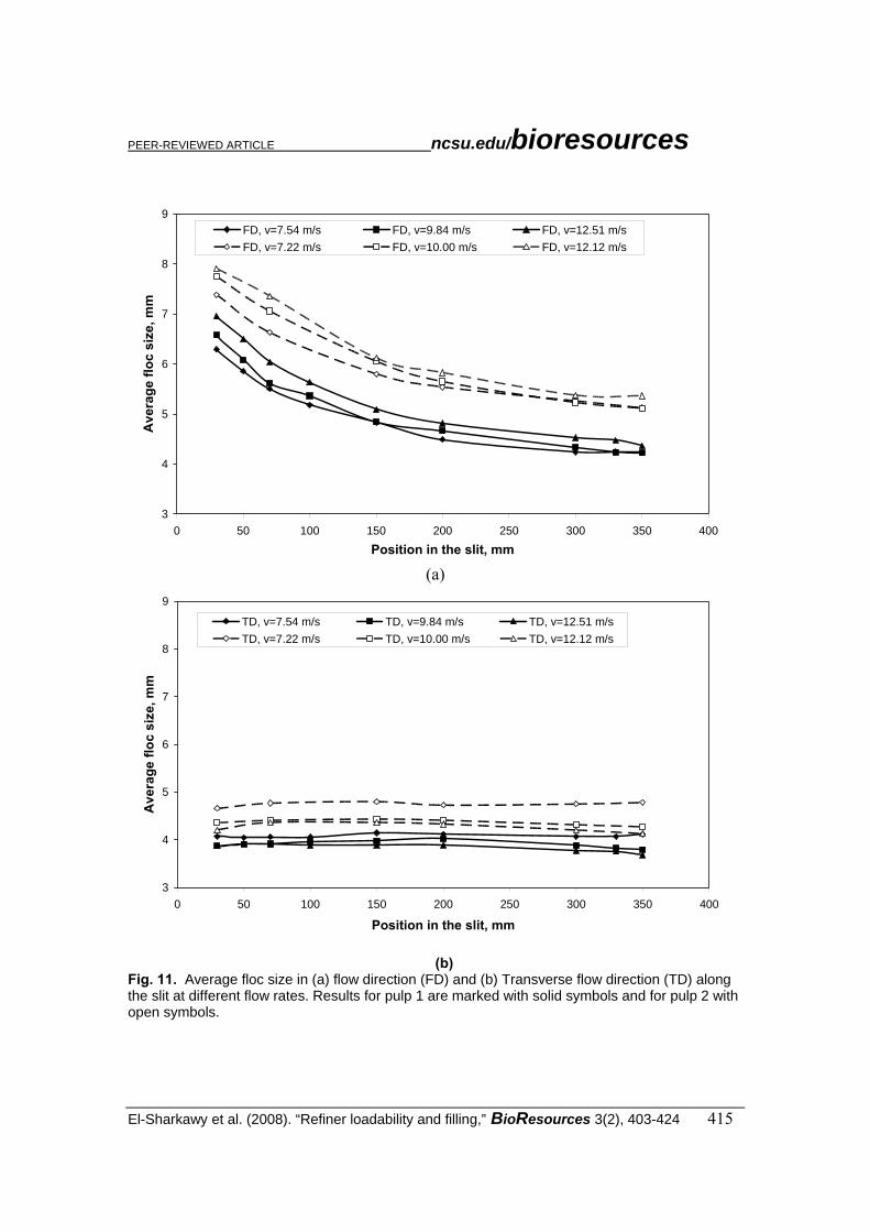
A pulp flow loop with a thin slit was designed to measure the development and breaking up of flocs under conditions similar to those in the filling grooves at typical refiner flow speeds. As pulps flow through the slit (5mm) and after the contraction from 40 mm size tube, the flocs are subjected to both deformation and stretching. The deformation seen as the flocs size has decreased at the end of the slit by 30% from its original size at the slit inlet. The floc deformation is due to turbulence and wall shear forces, which deform the flocs and reduce floc size along the slit, as shown in Figure 11.

PEER-REVIEWED ARTICLE ncsu.edu/bioresources
El-Sharkawy et al. (2008). “Refiner loadability and filling,” BioResources 3(2), 403-424 414
0.000
0.200
0.400
0.600
0.800
1.000
1.200
1.400
1.600
16600 16800 17000 17200 17400 17600 17800
Stator movement (Gap Posistion), μm
Net P
ower
Pulp 1 + 30% Pulp 2,cons. 2%
Pulp 1+ 30% Pulp 2, cons. 4%
Pulp 1+30% Pulp 2, cons. 5.5%
Fig. 10. Net power as a function of stator movement (gap closure) in refining pulp 1 with 30% addition of pulp 2 using a consistency of 2, 4 and 5.5%.
The stretching seen as the flocs aspect ratio (FD/TD) were 1.5-1.9 times larger in the FD than in the TD at the slit inlet. By the end of the slit the flocs retain its spherical shape and the floc aspect ratio reaches the level of 1.0, as shown in Fig. 12. The stretching strain is due to the abrupt contraction at the slit inlet. Pulp with long and coarse fibers form large and strong flocs that are able to resist floc size reduction along the slit compared to pulp of shorter and thinner fibers. The changes in floc sizes are also related to floc residence time inside the slit, and the longer the residence time, the greater the deformation and the more floc size changes due floc deformation. According to equation 2, the mean floc area reduction along the slit channel for pulp 1 was 32-40 % and for pulp 2 29-34 %. However, as seen in Fig. 13, the rate of change in the floc aspect ratio was very similar for both pulps. This behavior indicates that floc size depends on the residence time of flocs inside the slit or refiner grooves. The longer the residence the time, the greater the deformation and the more the floc size changes (e.g. through breaking of flocs) inside the refining area. Fiber Properties The fiber straightening or fiber curl occurring in pulp refining has recently attracted a lot of attention, as un-curled fibers have been found to improve tensile strength and load-transferring efficiency (Seth 2006; Page 1985; Mohlin 1996). Figure 14 shows the changes in average fiber length for pulps 1 and 2 refined under the same refining conditions with the three different fillings. Both conical and wide-bar disc fillings showed a straightening effect in refining, as the measured average fiber length tended to increase due to refining.
PEER-REVIEWED ARTICLE ncsu.edu/bioresources
El-Sharkawy et al. (2008). “Refiner loadability and filling,” BioResources 3(2), 403-424 415
3
4
5
6
7
8
9
0 50 100 150 200 250 300 350 400
Position in the slit, mm
Ave
rage
floc
siz
e, m
m
FD, v=7.54 m/s FD, v=9.84 m/s FD, v=12.51 m/sFD, v=7.22 m/s FD, v=10.00 m/s FD, v=12.12 m/s
(a)
3
4
5
6
7
8
9
0 50 100 150 200 250 300 350 400
Position in the slit, mm
Ave
rage
floc
siz
e, m
m
TD, v=7.54 m/s TD, v=9.84 m/s TD, v=12.51 m/sTD, v=7.22 m/s TD, v=10.00 m/s TD, v=12.12 m/s
(b) Fig. 11. Average floc size in (a) flow direction (FD) and (b) Transverse flow direction (TD) along the slit at different flow rates. Results for pulp 1 are marked with solid symbols and for pulp 2 with open symbols.

PEER-REVIEWED ARTICLE ncsu.edu/bioresources
El-Sharkawy et al. (2008). “Refiner loadability and filling,” BioResources 3(2), 403-424 416
1.00
1.20
1.40
1.60
1.80
2.00
0 10 20 30 40 50 60 70 80
Dimenionless position in the slit (x/d)
Asp
ect r
atio
(FD
/TD
)
P1,v=7.54 m/s P1,v=9.84 m/s P1,v=12.51 m/sP2,v=7.22 m/s P2,v=10.00 m/s P2,v=12.12 m/s
Fig. 12. Floc aspect ratio along the slit at different flow rates. Position is scaled with height of the slit. Results for pulp 1 are marked with solid symbols and for pulp 2 with open symbols.
1.00
1.20
1.40
1.60
1.80
2.00
0.001 0.01 0.1 1Time, s
Asp
ect r
atio
(FD
/TD
)
P1,v=7.54 m/s P1,v=9.84 m/s P1,v=12.51 m/sP2,v=7.22 m/s P2,v=10.00 m/s P2,v=12.12 m/s
Fig. 13. Floc aspect ratio as a function of time at different flow rates. Results for pulp 1 are marked with solid symbols and for pulp 2 with open symbols.

PEER-REVIEWED ARTICLE ncsu.edu/bioresources
El-Sharkawy et al. (2008). “Refiner loadability and filling,” BioResources 3(2), 403-424 417
Both fillings had a wide groove, which is assumed to be beneficial in reforming and relaxing the fibers after they have been subjected to impacts between the rotor and stator bars. The situation was different when using narrow-bar disc fillings, as the only noticeable effect was fiber cutting, with the cutting effect being greater in pulp 2 than in pulp 1. The big flocs of pulp 2 were easily trapped between bars and were therefore subject to more intensive cutting action than the short fibers and short flocs formed by pulp 1, which tended to break easily and pass through the refining zone. External fibrillation is another indispensable refining effect. A few studies have examined the importance of external fibrillation and its importance for strength properties (Casey 1960; Nanko 2003; Kang 2007). External fibrillation is also closely related to the formation of fines in refining. In the present study external fibrillation was observed by light microscope and image analysis, making it possible to calculate the pixel area of the fibril area divided by the total area of fibers (Ishisaki 1996; Kurhila 2005). Figure 15 shows the changes in external fibrillation against filling design. With all fillings, pulp 2 showed more external fibrillation than pulp 1, which can be explained, as the flocs formed by pulp 2 were able to resist high shear forces between fibers, resulting in friction that led to higher external fibrillation. The small flocs formed by pulp 1 were not so easily trapped between bars but passed through the filling grooves, especially in the wide grooves of conical fillings, which showed the smallest increase in external fibrillation. Narrow-bar disc fillings produced the highest external fibrillation due to the high shear forces of the filling. In lower cutting speed and greater groove width fillings, the fibers had more opportunities to flow through filling grooves rather than being trapped by the bars. Internal fibrillation is a major refining effect normally produced by the cyclic compression action of forces inside the refiner. The fiber saturation point, FSP, was measured with the solute exclusion technique and used as an indication of fiber swelling or internal fibrillation, as shown in Fig. 16. For all fillings, pulp 2 showed a smaller increase in fiber swelling (FSP) than pulp 1. The big flocs formed by pulp 2 fibers maintained a wide gap between rotor and stator, and the bigger the flocs, the less the fibers were subjected to forces, and the less they swelled. An increase in the cutting speed of fillings tends to increase the effect or the intensity of forces acting on fibers, causing more fiber strain and more cell wall breaking and accordingly greater fiber swelling. Therefore, conical fillings with the lowest cutting speed showed the smallest increase in swelling, whereas the narrow-bar fillings with the highest cutting speed showed the greatest increase in fiber swelling.
Pulp freeness is closely related to several phenomena in refining, such as external fibrillation, fibre shortening, and fines generation. Nevertheless, pulp freeness is still widely used as an indication of pulp quality after refining. Figure 17 shows the drop in pulp freeness due to refining for all fillings used. The drop in freeness was much smaller for pulp 2 than for pulp 1, irrespective of the type of filling used. For a certain type of pulp, refining with fillings with a higher cutting edge speed, such as narrow-bar fillings, showed the greatest drop in pulp freeness for both pulps. The higher the cutting speed, the more the fibers were cut, broken, and fibrillated, resulting in a high pulp surface area after refining and therefore a lower freeness level.

PEER-REVIEWED ARTICLE ncsu.edu/bioresources
El-Sharkawy et al. (2008). “Refiner loadability and filling,” BioResources 3(2), 403-424 418
‐8
‐6
‐4
‐2
0
2
4
6
Pulp 1 Pulp 2
Chan
es in
ave
age fib
er le
ngth
due
to refin
ing (%
)
Conical fi l l ing‐ CEL 0.67 km/s
Wide bar disk fi l l ing‐ CEL 1.068 km/s
Narrow bar disk fi l l ing‐ CEL 2.84 km/s
Fiber straightening
Fiber cutting
Fig. 14 Change in average fiber length in refining of pulp 1 and pulp 2 with different fillings.
0
10
20
30
40
50
60
70
80
90
Pulp 1 Pulp 2
Chan
es in
externa
l fibrillation
due
to refin
ing
Conical fi l l ing‐CEL 0.67km/s
Wide bar disk fi l l ing‐CEL 1.08 km/s
narrow bar disk fi l l ing‐CEL 2.84 km/s
Fig. 15. Change in average external fibrillation in refining of pulp 1 and pulp 2 with different fillings.

PEER-REVIEWED ARTICLE ncsu.edu/bioresources
El-Sharkawy et al. (2008). “Refiner loadability and filling,” BioResources 3(2), 403-424 419
0
5
10
15
20
25
30
35
40
Pulp 1 Pulp 2
Increa
se in
Fiber
Saturation Po
int (%
)
Coni ca l fi l l i ng Wide ba r di s k fi l l i ng Na rrow ba r di s k fi l l i ng
Fig. 16. Change in fiber saturation point (FSP) for pulp 1 and pulp 2 in refining with different fillings.
0
2
4
6
8
10
12
14
16
Pulp 1 Pulp 2
Drop in pulp free
ness due
to refin
ing
Coni ca l fi l l i ng‐CEL 0.67 km/s
Wide ba r di s c fi l l i ng‐CEL 1.068km/s )
Na rrow ba r di s c fi l l i ng‐CEL 2.84 km/s )
Fig. 17. Change in pulp freeness in refining of pulp 1 and pulp 2 with different fillings.

PEER-REVIEWED ARTICLE ncsu.edu/bioresources
El-Sharkawy et al. (2008). “Refiner loadability and filling,” BioResources 3(2), 403-424 420
DISCUSSION The loadability of a pulp refiner was examined in this study by assessing refining data such as total power, no-load power, and net power as a function of the refiner gap. The trapping point at which the fiber flocs are picked up between the rotor and stator was then linked to the filling design, fiber characteristics, and refining consistency. For certain fillings, long and coarse fibers were trapped and loaded early in the refiner compared to shorter and thinner fibers. At the same time, long and coarse fibers maintained a wider gap than short fibers. Flocculation experiments showed that long and coarse fibers formed bigger flocs than short and thin fibers. Although the flocs might stretch as they flow through the refiner grooves in the flow direction, they were able to regain their circular shape after a certain distance when the shear is decaying. The reduction in size was greater for flocs formed by thin and short fibers, while flocs formed by long and coarse fibers were able to maintain their shape without any major size reduction. Therefore, the flocs formed by long and coarse fibers were more stable and partially resist the reduction in size, which explains why flocs of this type maintain a wider refiner gap. The trapping point and gap size were strongly affected by the filling design, such as the groove width and the edge cutting speed. Under the same refining conditions, fillings with high cutting speed showed a smaller gap width than fillings with a lower cutting speed. When using fillings with a high cutting speed, there were hardly any differences in trapping point and gap width. Increasing the average fiber length and coarseness of the pulp by adding long fibers tended to increase the refiner gap and bring forward the trapping point, as fibers were trapped earlier in the closing gap. An increase in pulp consistency (in the range 2.0-5.5%) did not have the same effect as an increase in fiber length and coarseness, and differences in pulp consistency within that range hardly changed the gap width, trapping point, or refiner loadability. With all refiner fillings the fibers forming big flocs, because of their greater length and coarseness, showed less swelling due to less compression and bending in the refining zone. Fillings with a smaller groove width and high cutting speed showed a greater increase in swelling for both pulps compared to fillings with lower cutting speed. Wide groove fillings with lower cutting speed showed a straightening effect for both pulp types, but the straightening effect was less for pulp with long and coarse fibers. The refining effect was more a cutting effect without any straightening when fillings with high cutting speed were used, and long and coarse fibers were cut and shortened more intensively than fibers forming small flocs. When using fillings with high cutting speed, external fibrillation was greater than with fillings with lower cutting speed, and pulp forming bigger flocs was more sheared in the refining zone and therefore more fibrillated externally. Different refining effects are reflected as changes in pulp freeness, so the greatest drop in pulp freeness due to refining is obtained with high cutting speed fillings, and the changes in pulp freeness decrease as the filling cutting speed is decreased. The factors affecting the gap width and the loadability of the refiner, and how this is reflected in measured fiber properties and their relationships, are presented in Fig. 18.

PEER-REVIEWED ARTICLE ncsu.edu/bioresources
El-Sharkawy et al. (2008). “Refiner loadability and filling,” BioResources 3(2), 403-424 421
Fig. 18. Interrelations between filling design and pulp characteristics with reference to loadability and refining effects. CONCLUSIONS
1. The trapping point at which the pulp refiner starts to consume refining power is closely related to the fiber characteristics, where the effects of fiber length and coarseness are the dominant factors determining the gap width and trapping point. Other parameters such as refining consistency in the range of 2.0 – 5.5% have a smaller effect compared to the effect of increasing fiber length and coarseness.
2. The trapping point is also related to filling design, with fillings having wide grooves and low cutting edge speed imparting a mild effect on fiber flocs. Therefore, flocs of different size have clearly different effects on gap width and fiber trapping under the same refining conditions. On the other hand, narrow-bar fillings with high cutting speed tend to break flocs of different fibers at the same rate, and differences in floc sizes do not have any effect on gap width and trapping point.
3. Under deformation, pulp flocs tend to stretch in the flow direction, and when the stress is reduced the flocs regain their original spherical shape. The pulps containing long and coarse fibers tend to have bigger and stronger flocs in both flow and cross flow direction. The floc reduction due to shear stress and deformation is less for flocs of long and coarse fibers compared to fibers of short

PEER-REVIEWED ARTICLE ncsu.edu/bioresources
El-Sharkawy et al. (2008). “Refiner loadability and filling,” BioResources 3(2), 403-424 422
and thin fibers, so they maintain a wider gap and are trapped earlier as the gap closes.
4. Refining effects such as swelling, external fibrillation, fiber cutting, or
straightening are highly dependent on the filling characteristics, such as groove width and the cutting speed of the filling. Fillings with a high cutting edge speed produce a greater cutting effect, more swelling, and more external fibrillation, which is reflected as a bigger drop in pulp freeness due to refining. Wide-bar fillings with low cutting speed produce a greater straightening effect, less swelling, and less external fibrillation and therefore a smaller change in pulp freeness.
REFERENCES CITED Arjas, A., Ario, M., and Ryti, N. (1970) “The influence of residence time distribution on
the besting results of a mill-scale conical refiner,” Paperi Puu 10, 639-649. Batchelor, W., Lundin, T., and Fardim, P. (2006) “A method to estimate fiber trapping in
low-consistency refining,” Tappi J. 5(8), 31-36. Batchelor, W. J., and Ouellet, D. (2001). “Estimating forces on fibers in refining,” Fourth
International Refining Confernce, 47-60. Brecht, W., and Siewert, W. H. (1996). “Zur theoretischen Berurteilung des
Mahlprozesses moderner Mahlmaschinen,” Das Papier 20(1), 38-42. Casey, J. P. (ed.) (1960). Pulp and Paper Chemistry and Chemical Technology, Vol. 2,
Interscience Publishers, Inc., New York, USA, 687-689. Ebeling, K. (1980) “A critical review of current theories for the refining of chemical
pulps,” Symposium of Fundamental Concepts of Refining, Appleton, The institute of paper chemistry, pp. 1-38.
Fox, T. S., Brodkey, R. S., and Nissan, A. H.(1979). “High speed photography of stock transport in a disc refiner,” Tappi J. 62(3), 55-58.
Giertz, H. W. (1980). “The influence of beating on individual fibers and the casual effects on paper properties,” International Symposium on Fundamental Concepts of Refining, Institute of Paper Chemistry, Appleton, USA, 87-92.
Hietanen, S., and Ebeling, K. (1990) “A new hypothesis for the mechanism of refining,” Paperi Puu 72(2), 37-44.
Higgins, H. G., and De Yong, J. (1961). “The beating process – Primary effects and their influence on paper properties,” Trans. of the 2nd, Fundamental Research Symposium, Oxford, UK, 651-690.
Ishisaki, M., and Naito, T. (1996) “Microscopical evaluation of external fibrillation of mechanical pulps,” Proceedings of the 63rd, Japan TAPPI Pulp and Paper Research Conference, Tokyo, Japan, 62-65.
Kang, T. (2007) “Role of external fibrillation in pulp and paper properties,” doctoral thesis, Helsinki University of Technology, Reports, Series A28, Espoo, Finland.
Karema, H., and Salmela, J. (2001) “Predication of paper formation by fluidization and reflocculation experiments,” 12th, Fundamental Research Symposium, UK, 559-589.

PEER-REVIEWED ARTICLE ncsu.edu/bioresources
El-Sharkawy et al. (2008). “Refiner loadability and filling,” BioResources 3(2), 403-424 423
Kellomäki, M., and Karema, H. (1999). “Fiber flocculation measurement in pipe flow by digital image analysis.” Proc. TAPPI Intl. Paper Physics Conf. 461-463.
Kerekes, R. J., and Senger, J. J. (2006) “Characterizing refining action in low-consistency refiners by forces on fibers,” J. Pulp Pap. Sci. 32(1), 1-8.
Kerkes, R. J., Soszynski, R. M., and Tam Doo, P. A. (1985) “The flocculation of pulp fibers,” Fundamental Research Symposium, Oxford, UK, 265-310.
Kurhila, A. (2005) “Developing a method for characterization of fiber external fibrillation. Measurement of external fibrillation,” M.Sc. thesis, Helsinki University of Technology, Espoo, Finland, p.96.
Maloney, T. C., and Paulapuro, H. (1999). “The formation of pores in the cell wall,” J. Pulp Pap. Sci. 25(12), 430-436.
Martinez, D. M., and Kerekes, R. J. (1994). “Forces on fibers in low-consistency refining,” Tappi J. 77(12), 119-123.
Martinez, D. M., Batchelor, W. J., Kerekes, R. J., and Ouellet, D. (1997) “Forces on fibers in low-consistency refining: Normal forces,” J. Pulp Pap. Sci. 23(1), J11-J18.
Molin, U-B., Dahlbom, J., and Hornatowska, J. (1996). “Fiber deformation and sheet strength,” Tappi J. 79 (6), 105-111.
Nanko, H. (2003) “Mechanisms of fiber bond formation,” Fundamentals of Paper-making, Trans. of the 9th, Fundamental Research Symposium, Cambridge, U.K., 783-830.
Page, D. H., Seth R. S., Jordan, B. D., and Barbe, M. C. (1985) “Curl, crimps, kinks and microcompressions in pulp fibers – Their origin, measurements and significance,” Papermaking Raw Materials, Trans. of the 1985 Fundamental Research Symposium, Oxford, 183-227.
Page, D. H. (1989) “The beating of chemicals pulps - The action and the effects,” Papermaking Raw Materials, Trans. of the 9th, Fundamental Research Symposium, Cambridge, UK, 1-37.
Page, D. H., Kosky, J., and Booth, D. (1962). “Some initial observation on the action of beater,” B.P. & B.I.R.A. Bulletin October, 15-22.
Range, H. F. (1951). “The process viewed as a problem of lubrication and lubricant behaviour,” Symposium of Beating, Proc. Tech. Sect. 32(3), BPBMA, 360-370.
Richardson, J. D., Riddell, M., and Burrell, P. (2003). “Experiences with FiberLab V3.0 analyzer for Measuring Fiber Cross-sectional Dimensions,” 57th APPITA Annual Conference, Melbourne, Australia, May 5-7, pp. 315-322.
Rihas, J. (1995). “Low consistency refining, theory vs practice,” 3rd International Refining Seminar, Atlanta, 20-22 March, paper 10.
Seth, R. S. (2006) “The importance of fiber straightness for pulp strength,” Pulp and Pap Canada, 107(1), 34-42.
Stone, J. E., Scallan, A. M., and Abrahamson, B. (1968) “The Influence of beating on cell wall swelling and internal fibrillation,” Svensk Papperstidning 19(10), 687-694.
Steenberg, B. (1951). In discussion, Symposium of Beating, Proc. Tech. Sect. 32(3), BPBMA, 388-396.
Steen, M. (1989) “A concept for fiber flocculation in turbulent flow,” Fundamental Research Symposium, Cambridge, UK, 250-274.

PEER-REVIEWED ARTICLE ncsu.edu/bioresources
El-Sharkawy et al. (2008). “Refiner loadability and filling,” BioResources 3(2), 403-424 424
Stoere, P., Nazhad, M. M., and Kerekes, R. J. (2001). “An experimental study of the effect of refining on formation,” Tappi J. 84(7), 1-9.
Switzer, L. H., and Klingenberg, D. J. (2003). “Simulations of fiber floc dispersion in linear flow fields,” Nord. Pulp Paper Res. J. 18(2), 141-144.
Salmela, J., and Kataja, M. (2005). “Floc rupture and re-flocculation in turbulent shear flow,” 13th, Fundamental Research Symposium, Cambridge, UK, 35-50.
Turunen, M., le Ny, C., Tienvieri, T., and Niinimäki, J. (2005). “Comparison of fibre morphology analysers,” APPITA J. 58(1), 28-32.
Westman, L. (1985) “Idling losses in the low-consistency refining of chemical pulp,” Svensk Papperstidning 87 (3), R8-R13.
Article submitted: January 28, 2008; Peer-review completed: Feb. 25, 2008; Revision received and accepted: March 11, 2008; Published: March 17, 2008