effects of alloying elements on microstructure and …dl.iran-mavad.com/sell/trans/en/effects of...
TRANSCRIPT
Materials Science and Engineering A254 (1998) 282–295
Effects of alloying elements on microstructure and fractureproperties of cast high speed steel rolls
Part I: Microstructural analysis
Keun Chul Hwang a, Sunghak Lee a, Hui Choon Lee b,*a Center for Ad6anced Aerospace Materials, Pohang Uni6ersity of Science and Technology, Pohang 790-784, South Korea
b Roll Technology Department, Kangwon Industries, Pohang 790-370, South Korea
Received 17 February 1998
Abstract
A study was made of the effects of alloying elements on microstructural factors of six high speed steel (HSS) rolls manufacturedby centrifugal casting method. Particular emphasis was placed on the role of hard carbides located along solidification cellboundary and the type of the martensite matrix. Microstructural observation, X-ray diffraction analysis, and hardnessmeasurement were conducted on the rolls to identify carbides. Various types of carbides were formed depending on the contentsof strong carbide forming elements. In the rolls containing the high Cr content, MC carbides inside cells and M7C3 carbides alongcell boundaries were primarily formed, while in the rolls containing the high W and Mo contents, MC carbides inside the cellsand fibrous M2C carbides in the intercellular regions were dominantly formed. The most important microstructural factoraffecting overall roll hardness was the intercellular carbides and their distribution. The effects of alloying elements were analyzedon the basis of the liquidus surface diagram, suggesting that the proper contents of carbon, tungsten, molybdenum, chromium,and vanadium were 1.9–2.0, 3–4, 3–4, 5–7, and 5–6%, respectively. © 1998 Elsevier Science S.A. All rights reserved.
1. Introduction
High speed steel (HSS), widely used for tools, ischaracterized of excellent hardness, wear resistance, andhigh-temperature properties. Recently, HSS has beenapplied to roll materials in order to make rolled plateshave homogeneous thickness and uniform surface dur-ing hot rolling, thereby leading to enhanced surfacequality of rolled plates and extended roll life [1,2].These HSS rolls have different microstructure and char-acteristics from high speed tool steels. When manufac-turing tool steels, the cast structure is destroyed in thesubsequent deformation such as forging, and the finalmicrostructure after heat-treatment consists of tem-pered martensite containing fine and well-distributedcarbides. In the case of the HSS rolls, the cast structurecontaining coarse carbides is left, and the matrix aloneis changed to tempered martensite after heat-treatment.
The carbon content in the HSS rolls is generally1.5–2.0%, most of which is combined with such strongcarbide formers as V, W, and Mo [3–5]. The rest ofcarbon, 0.3–0.6%, is contained inside the matrix, andforms lath-type martensite when the carbon content isbelow 0.4%, while plate-type martensite when it isabove 0.4% [6]. Coarse carbides are generally segre-gated along cell boundaries, therefore, overall roll hard-ness increases, but fracture toughness tends todeteriorate. In addition, the increased rolling force andthe temperature rise and drop due to the contact ofrolled plates and coolant result in thermal fatiguecracks, roughening the roll surface, or initiating internalcracks which might lead to unexpected fracture [7,8].Consequently, the microstructural factors such as size,volume fraction, distribution of coarse carbides, andthe characteristics of the martensitic matrix play impor-tant roles in enhancing the roll properties.
In this study, attempts are made to identify thecorrelation between microstructure and mechanicalproperties of cast HSS rolls. It also intends to presentessential conditions in alloy designing and manufactur-
* Corresponding author. Tel.: +82 562 2792715; fax: +82 5622792399.
0921-5093/98/ - see front matter © 1998 Elsevier Science S.A. All rights reserved.
PII S0921-5093(98)00626-1
K.C. Hwang et al. / Materials Science and Engineering A254 (1998) 282–295 283
Table 1Chemical compositions of HSS rolls investigated (wt.%)
S Ni AlRoll C W Mo V Cr Weq*Si Mn P
5.00.02A 1.95 1.21.6 50.051.7 5.1 5.5 1.0 0.9 50.0550.05 1.2 0.02B1 1.95 2.0 3.0 3.6 8.09.0 1.0 0.9 50.05
8.00.021.2B2 1.95 2.0 3.0 50.055.0 9.0 1.0 0.9 50.0550.05 1.2 0.02C1 1.90 5.0 10.02.5 5.0 5.0 1.0 0.9 50.05
15.00.021.2C2 1.90 5.0 5.0 50.055.0 5.0 1.0 0.9 50.0550.05 1.2 0.02D 15.01.45 5.0 5.0 5.0 5.0 1.0 0.9 50.05
* Weq=W+2Mo; Tungsten equivalent.
ing by investigating the effects of alloying elements. Sixrolls were fabricated by varying the contents of C, W,Mo, Cr, and V, and their respective effects on mi-crostructure and hardness were investigated. The rollswere designed in such a way that the formation ofhomogeneously distributed hard carbides was maxi-mized by adjusting the content of carbon and carbideformers to enhance wear resistance, while minimizingthe amount of intercellular carbides. Intensive investi-gation was conducted on various kinds of carbides toanalyze the correlation between microstructural factorsand mechanical properties.
2. Experimental
Materials used in this study were six HSS rolls man-ufactured by centrifugal casting method, whose chemi-cal compositions and tungsten equivalents(Weq=W+2Mo) are listed in Table 1. The basic com-position of the rolls is 1.9C–5.0V–5.0Cr–1.OSi–0.9Mn–1.2Ni (wt.%), and the rolls are designed to beable to investigate the effect of tungsten equivalent byvarying the contents of W and Mo. Roll-A contains thelowest tungsten and molybdenum contents of 1.6–1.7%. The compositions of other rolls are varied toinvestigate the effects of other elements: i.e., V and Crvariations in Rolls-B1 and -B2, increased tungstenequivalent in Rolls-C1 and -C2, and reduced carbon inRoll-D. The rolls were manufactured by a laboratory-scale horizontal centrifugal casting apparatus. The meltwas charged into the high-speed revolving mold to forma shell part. Prior to solidification, a core part ofnodular graphite cast iron was introduced to producethe rolls with 400 mm in diameter (shell thickness of 65mm) and 600 mm in length. The roll samples wereobtained from the shell part, and were austenitized at980–1100°C, water quenched, and double-tempered at495–635°C.
The samples were polished and etched in 3% nital,and were observed by an optical microscope and ascanning electron microscope (SEM). Compositions ofcarbides and the matrix were quantitatively analyzed byenergy dispersive spectroscopy (EDS) and wave-length
dispersive spectroscopy (WDS). Carbides were exam-ined using Murakami etchant [9] (3 g K3Fe(CN)6+10gNaOH+100 ml Hz2O), in which M2C (black), M7C3
(light pink), and M6C (pink) carbides are selectivelyetched but not the matrix and MC carbides. The cellsize and the volume fraction of respective carbides werequantitatively analyzed using an image analyzer. Addi-tionally, the matrix was deeply etched in an etchant of5g FeCl3+10 ml HNO3+3 ml HCl+87 ml ethylalcohol [10] to observe the three-dimensional shape ofcarbides by an SEM. An X-ray diffractometer was usedto confirm the kind of carbides and to measure theamount of retained austenite (g). Overall bulk hardnessof the rolls, microhardness of the matrix, and micro-hardness of carbides were also measured by a vickershardness tester under 30 kg, 1 kg, and 10 g loads,respectively.
3. Results
3.1. As-cast microstructure and hardness
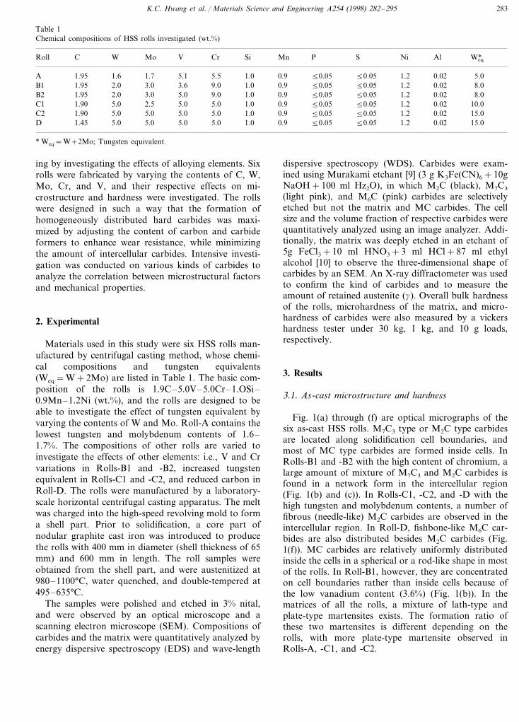
Fig. 1(a) through (f) are optical micrographs of thesix as-cast HSS rolls. M7C3 type or M2C type carbidesare located along solidification cell boundaries, andmost of MC type carbides are formed inside cells. InRolls-B1 and -B2 with the high content of chromium, alarge amount of mixture of M7C3 and M2C carbides isfound in a network form in the intercellular region(Fig. 1(b) and (c)). In Rolls-C1, -C2, and -D with thehigh tungsten and molybdenum contents, a number offibrous (needle-like) M2C carbides are observed in theintercellular region. In Roll-D, fishbone-like M6C car-bides are also distributed besides M2C carbides (Fig.1(f)). MC carbides are relatively uniformly distributedinside the cells in a spherical or a rod-like shape in mostof the rolls. In Roll-B1, however, they are concentratedon cell boundaries rather than inside cells because ofthe low vanadium content (3.6%) (Fig. 1(b)). In thematrices of all the rolls, a mixture of lath-type andplate-type martensites exists. The formation ratio ofthese two martensites is different depending on therolls, with more plate-type martensite observed inRolls-A, -C1, and -C2.
K.C. Hwang et al. / Materials Science and Engineering A254 (1998) 282–295284
Fig. 1. (a) through (f) Optical micrographs of the shell region of six as-cast HSS rolls. Nital etched.
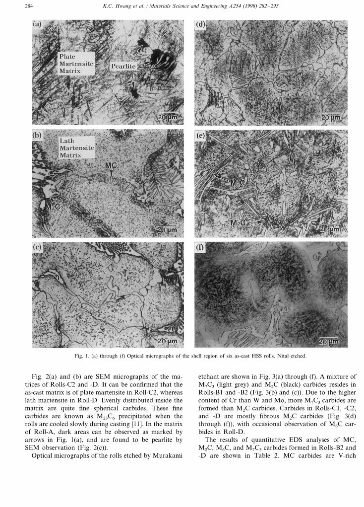
Fig. 2(a) and (b) are SEM micrographs of the ma-trices of Rolls-C2 and -D. It can be confirmed that theas-cast matrix is of plate martensite in Roll-C2, whereaslath martensite in Roll-D. Evenly distributed inside thematrix are quite fine spherical carbides. These finecarbides are known as M23C6 precipitated when therolls are cooled slowly during casting [11]. In the matrixof Roll-A, dark areas can be observed as marked byarrows in Fig. 1(a), and are found to be pearlite bySEM observation (Fig. 2(c)).
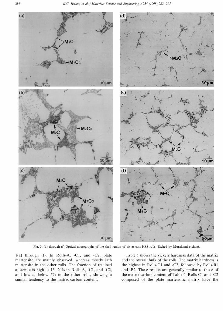
Optical micrographs of the rolls etched by Murakami
etchant are shown in Fig. 3(a) through (f). A mixture ofM7C3 (light grey) and M2C (black) carbides resides inRolls-B1 and -B2 (Fig. 3(b) and (c)). Due to the highercontent of Cr than W and Mo, more M7C3 carbides areformed than M2C carbides. Carbides in Rolls-C1, -C2,and -D are mostly fibrous M2C carbides (Fig. 3(d)through (f)), with occasional observation of M6C car-bides in Roll-D.
The results of quantitative EDS analyses of MC,M2C, M6C, and M7C3 carbides formed in Rolls-B2 and-D are shown in Table 2. MC carbides are V-rich
K.C. Hwang et al. / Materials Science and Engineering A254 (1998) 282–295 285
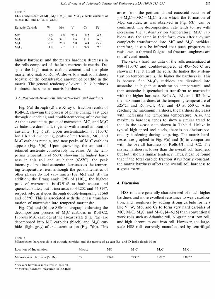
carbides (V4C3 in chemical stoichiometry) containingmostly V with small amounts of W, Mo, Cr, and Fe.M2C and M6C carbides are carbides containing Moand W, and M7C3 carbides are Cr-containing ones.
Table 3 shows the microhardness data of these car-bides. The hardness of MC carbides formed inside cellsis considerably high at 2740 VHN, while those of M2C,M6C, and M7C3 carbides in the intercellular region are2230, 1890, and 2380 VHN, respectively, showing muchhigher hardness than the martensitic matrix (650VHN). These microhardness values are close to thosereported in previous literatures [12–14].
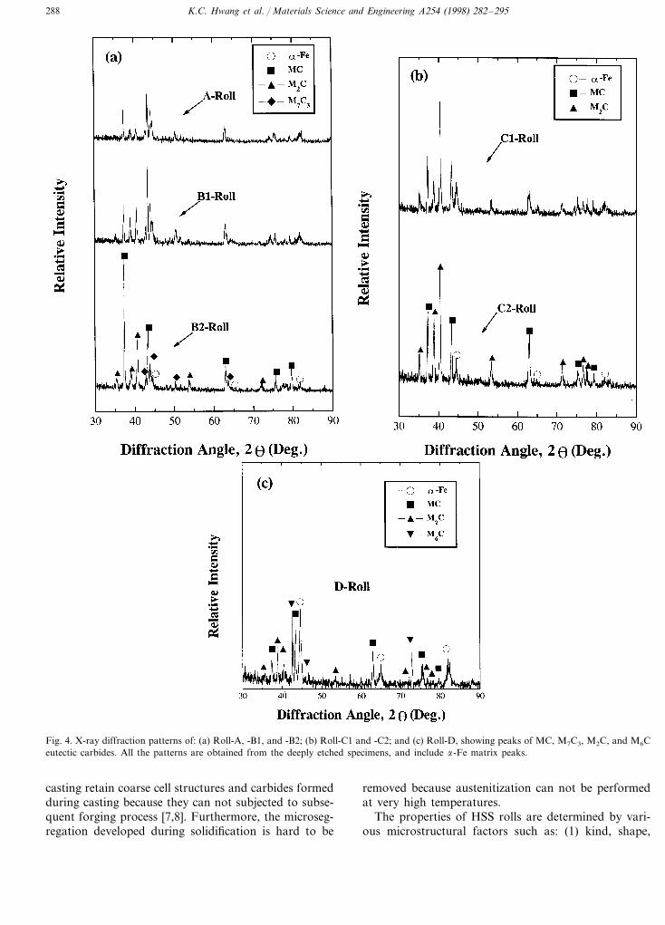
After the matrix and fine carbides were removed bydeep-etching method, an X-ray diffraction analysis wasconducted on the carbides protruded on the surface, theresults of which are shown in Fig. 4(a) through (c).Rolls-A, -B1, and -B2 consist of MC, M2C, and M7C3
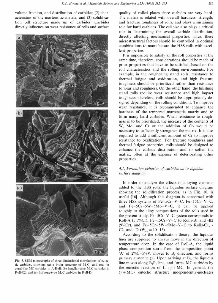
carbides (Fig. 4(a)), Rolls-C1 and -C2 of MC and M2Ccarbides (Fig. 4(b)), and Roll-D of MC, M2C, and M6Ccarbides (Fig. 4(c)). Fig. 5(a) through (c) show three-di-mensional SEM observations of the protruded carbides.The typical shape of M7C3 carbides is of brain structure(Fig. 5(a)), while MC carbides of either rod-like (Fig.5(a)) or coral-like (Fig. 5(b)) shapes grown into cellboundaries from inside cells. M2C carbides shapedfibrous in Fig. 3(e) are observed in lamellar plates inthree-dimension (Fig. 5(b)), and M6C carbides are typi-cally shaped in fishbone-type with midplanes (Fig. 5(c)).
Table 4 lists the results of quantitative analyses byimage analyzer, WDS, and X-ray diffraction methods,respectively, on cell size, volume fraction of carbides,carbon content in the matrix, and volume fraction ofretained austenite. Cells in Rolls-A, -B1, and -B2 aresized by 95, 84, and 76 mm, respectively, showing adecrease as tungsten equivalent increases, and the frac-tion of MC carbides is considerably low at 5%. Al-though a small amount of M2C carbides is found inthese rolls, they are counted as M7C3 in the quantitativeanalyses of Table 4 because they are usually mixed withM7C3. The fraction of M7C3 carbides in Rolls-B1 and-B2 containing a large amount of Cr (9%) is high atabout 15%, resulting in a considerably higher fractionof overall carbides at around 17–19% than Roll-A’s(9.1%). The cell sizes of Rolls-C1 and -C2 containingthe increased contents of W and Mo are about 90 mm,and their fraction of MC carbides is 10–12%, largerthan Rolls-B1 and -B2’s. Due to the large amount ofM2C carbides in Rolls-C1 and -C2, the overall fractionof carbides ranges around 18–24%. The cell sizes ofRoll-D, containing the high contents of W and Mo butwith the reduced carbon content (1.45%), are the largestat around 110 mm. The fraction of MC carbides ismeasured to be about 8%, higher than in Rolls-A, -B1,and -B2 but lower than in Rolls-C1 and -C2. In termsof the total carbide fraction, only Roll-A is low atabout 9%, while the rest ranges at 18–24%. The carboncontent in the matrix of Rolls-A, -C1, and -C2 is highat above 0.6%, but low at below 0.4% in other rolls.These carbon content data are congruent with themorphology of the martensitic matrix as shown in Fig.
Fig. 2. SEM micrographs of: (a) Roll-C2; (b) Roll-D; and (c) Roll-A;showing the martensitic matrix in the as-cast condition. Note thepearlite structure in (c). Nital etched.
K.C. Hwang et al. / Materials Science and Engineering A254 (1998) 282–295286
Fig. 3. (a) through (f) Optical micrographs of the shell region of six as-cast HSS rolls. Etched by Murakami etchant.
1(a) through (f). In Rolls-A, -C1, and -C2, platemartensite are mainly observed, whereas mostly lathmartensite in the other rolls. The fraction of retainedaustenite is high at 15–20% in Rolls-A, -C1, and -C2,and low at below 6% in the other rolls, showing asimilar tendency to the matrix carbon content.
Table 5 shows the vickers hardness data of the matrixand the overall bulk of the rolls. The matrix hardness isthe highest in Rolls-C1 and -C2, followed by Rolls-B1and -B2. These results are generally similar to those ofthe matrix carbon content of Table 4. Rolls-C1 and -C2composed of the plate martensitic matrix have the
K.C. Hwang et al. / Materials Science and Engineering A254 (1998) 282–295 287
Table 2EDS analysis data of MC, M2C, M6C, and M7C3 eutectic carbides ofas-cast B2- and D-Rolls (wt.%)
Cr FeEutectic Carbide W Mo V
8.2 4.3MC 9.3 4.8 73.58.6 11.1M2C 36.6 37.1 6.5
4.45.0 25.726.3M6C 38.711.1 36.9M7C3 4.4 7.7 39.8
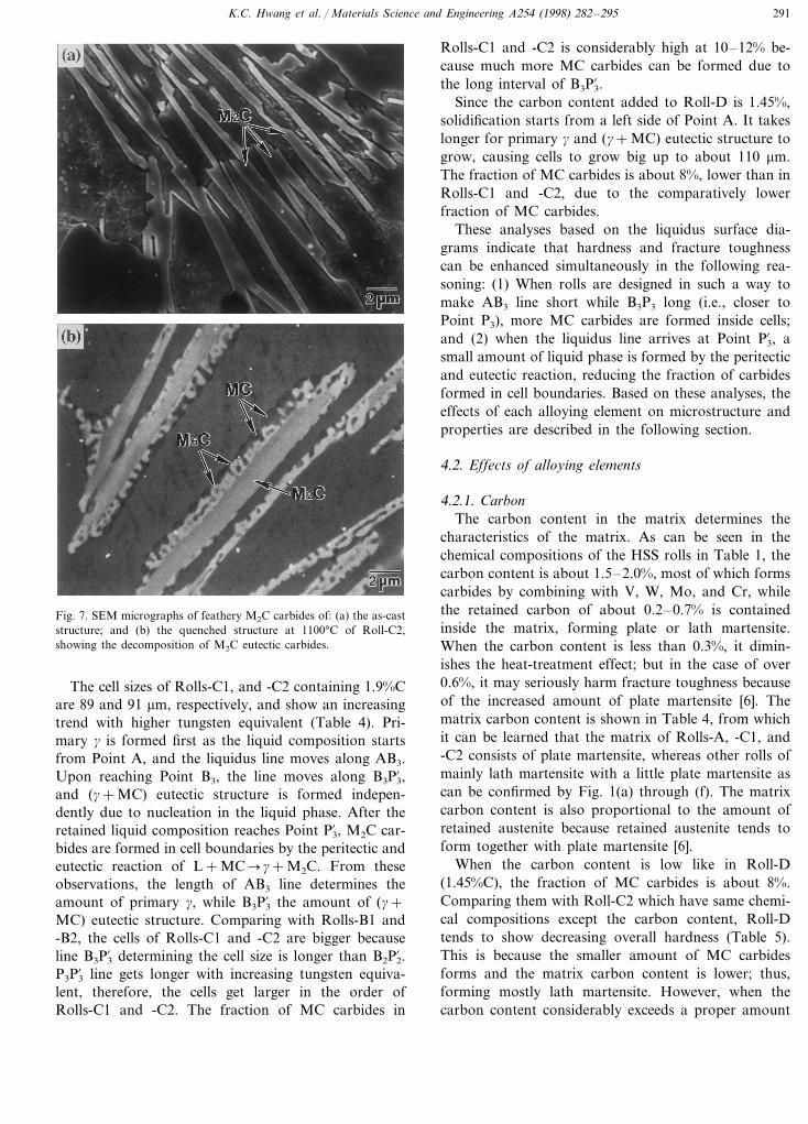
arises from the peritectoid and eutectoid reaction ofg+M2C�MC+M6C; from which the formation ofM6C carbides, as was observed in Fig. 6(b), can beconfirmed. The decomposition rate tends to rise withincreasing the austenitization temperature. M2C car-bides stay the same in their form even after they arecompletely transformed into MC and M6C carbides,therefore, it can be inferred that such properties asresistance to thermal fatigue and fracture toughness arenot affected much.
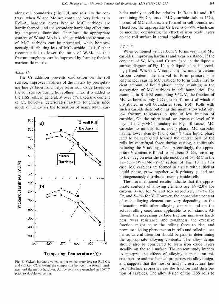
The vickers hardness data of the rolls austenitized at980–1100°C and double-tempered at 495–635°C areshown in Fig. 8. In all the rolls, the higher the austeni-tization temperature is, the higher the hardness is. Thisis because fine M23C6 carbides are dissolved intoaustenite at higher austenitization temperature, andthen austenite is quenched to transform to martensitewith the higher hardness. Rolls-A, -B1, and -B2 showthe maximum hardness at the tempering temperature of525°C, and Rolls-C1, -C2, and -D at 550°C. Afterreaching the maximum hardness, the hardness decreaseswith increasing the tempering temperature. Also, themaximum hardness tends to show a similar trend tothat in the as-cast state shown in Table 5. Unlike intypical high speed tool steels, there is no obvious sec-ondary hardening during tempering. The matrix hard-nesses are graphed in Fig. 9(a) and (b) in comparisonwith the overall hardness of Rolls-C1, and -C2. Thematrix hardness is lower than the overall roll hardness,but both show a similar tendency. Thus, it can be foundthat if the total carbide fraction stays nearly constant,the matrix hardness affects the overall roll hardness toa great extent.
4. Discussion
HSS rolls are generally characterized of much higherhardness and more excellent resistance to wear, oxidiza-tion, and roughness by adding strong carbide formerslike V, W, Mo, and Cr to form very hard carbides ofMC, M2C, M6C, and M7C3 [4–6,15] than conventionalwork rolls such as Adamite roll, Ni-grain cast iron roll,and high chromium cast iron roll. However, the large-scale HSS rolls currently manufactured by centrifugal
highest hardness, and the matrix hardness decreases inthe rolls composed of the lath martensitic matrix. De-spite the high matrix carbon content and the platemartensitic matrix, Roll-A shows low matrix hardnessbecause of the considerable amount of pearlite in thematrix. The general tendency of overall bulk hardnessis almost the same as matrix hardness.
3.2. Post-heat-treatment microstructure and hardness
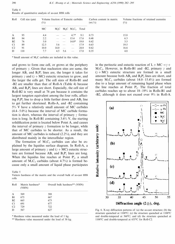
Fig. 6(a) through (d) are X-ray diffraction results ofRoll-C2, showing the process of phase change as it goesthrough quenching and double-tempering after casting.At the as-cast state, peaks of martensite, MC, and M2Ccarbides are dominant, together with a small amount ofaustenite (Fig. 6(a)). Upon austenitization at 1100°Cfor 1 h and quenching, peaks of martensite, MC, andM2C carbides remain, and new peaks of M6C carbidesappear (Fig. 6(b)). Upon quenching, the amount ofretained austenite considerably increases. At the tem-pering temperature of 560°C showing the highest hard-ness in this roll and at higher (635°C), the peakintensity of retained austenite decreases as the temper-ing temperature rises, although the peak intensities ofother phases do not vary much (Fig. 6(c) and (d)). Inaddition, the Bragg angle (2u) of (110)a, the highestpeak of martensite, is 43.914° at both as-cast andquenched states, but it increases to 44.202 and 44.376°,respectively, as it goes through double-tempering at 560and 635°C. This is associated with the phase transfor-mation of martensite into tempered martensite.
Fig. 7(a) and (b) are SEM micrographs showing thedecomposition process of M2C carbides in Roll-C2.Fibrous M2C carbides at the as-cast state (Fig. 7(a)) aredecomposed into MC carbides (black) and M6C car-bides (light grey) after austenitization (Fig. 7(b)). This
Table 3Microvickers hardness data of eutectic carbides and the matrix of as-cast B2- and D-Rolls (load; 10 g)
MCLocation of Indentation Matrix M7C3M6CM2C
2380**1890*2230*2740650Microvickers Hardness (VHN)
* Vickers hardness measured in D-Roll.** Vickers hardness measured in B2-Roll.
K.C. Hwang et al. / Materials Science and Engineering A254 (1998) 282–295288
Fig. 4. X-ray diffraction patterns of: (a) Roll-A, -B1, and -B2; (b) Roll-C1 and -C2; and (c) Roll-D, showing peaks of MC, M7C3, M2C, and M6Ceutectic carbides. All the patterns are obtained from the deeply etched specimens, and include a-Fe matrix peaks.
casting retain coarse cell structures and carbides formedduring casting because they can not subjected to subse-quent forging process [7,8]. Furthermore, the microseg-regation developed during solidification is hard to be
removed because austenitization can not be performedat very high temperatures.
The properties of HSS rolls are determined by vari-ous microstructural factors such as: (1) kind, shape,
K.C. Hwang et al. / Materials Science and Engineering A254 (1998) 282–295 289
volume fraction, and distribution of carbides; (2) char-acteristics of the martensitic matrix; and (3) solidifica-tion cell structure made up of carbides. Carbidesdirectly influence on wear resistance of rolls and surface
quality of rolled plates since carbides are very hard.The matrix is related with overall hardness, strength,and fracture toughness of rolls, and plays a sustainingrole for hard carbides. The cell size also plays a criticalrole in determining the overall carbide distribution,directly affecting mechanical properties. Thus, thesemicrostructural factors should be controlled in optimalcombinations to manufacture the HSS rolls with excel-lent properties.
It is impossible to satisfy all the roll properties at thesame time, therefore, considerations should be made ofprior properties that have to be satisfied, based on theroll characteristics and the rolling environments. Forexample, in the roughening stand rolls, resistance tothermal fatigue and oxidization, and high fracturetoughness should be prioritized rather than resistanceto wear and roughness. On the other hand, the finishingstand rolls require wear resistance and high impacttoughness, therefore, rolls should be appropriately de-signed depending on the rolling conditions. To improvewear resistance, it is recommended to enhance thehardness of the tempered martensitic matrix and toform many hard carbides. When resistance to rough-ness is to be prioritized, the increase of the contents ofW, Mo, and Cr or the addition of Co would benecessary to sufficiently strengthen the matrix. It is alsorequired to add a sufficient amount of Cr to improveresistance to oxidization. For fracture toughness andthermal fatigue properties, rolls should be designed toenhance the carbide distribution and to soften thematrix, often at the expense of deteriorating otherproperties.
4.1. Formation beha6ior of carbides as to liquidussurface diagram
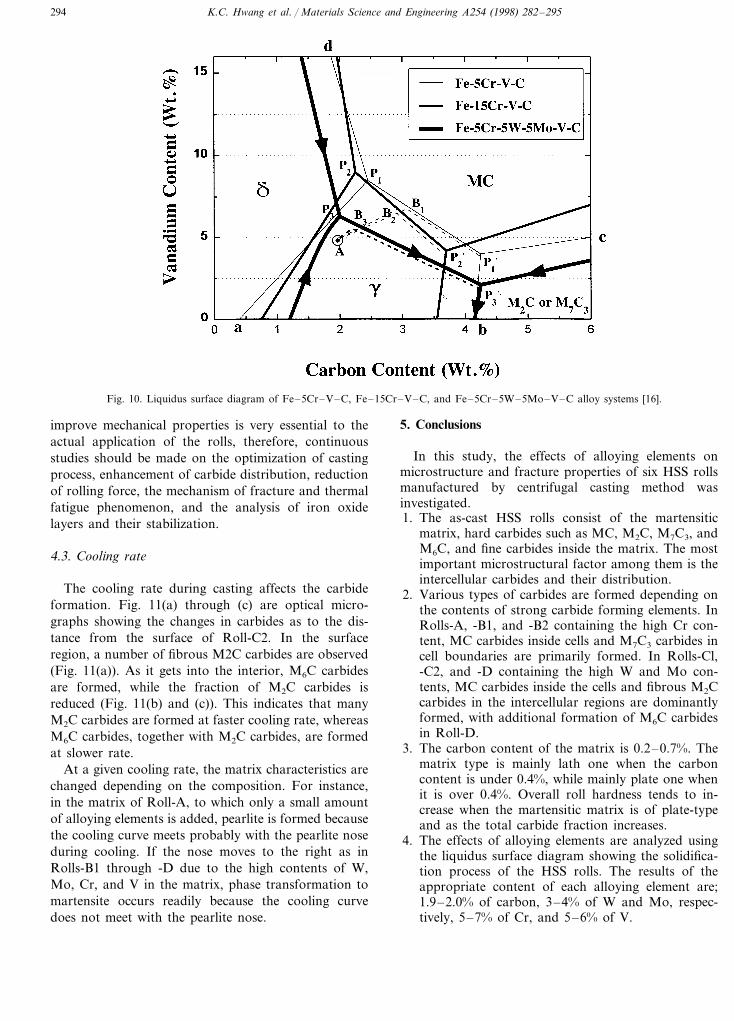
In order to analyze the effects of alloying elementsadded to the HSS rolls, the liquidus surface diagramshowing the solidification process, as in Fig. 10, isuseful [16]. Although this diagram is concerned withthree HSS systems of Fe–5Cr–V–C, Fe–15Cr–V–C,and Fe–5Cr–5W–5Mo–V–C, it can be appliedroughly to the alloy compositions of the rolls used inthe present study. Fe–5Cr–V–C system corresponds toRoll-A (5.5%Cr), Fe–15Cr–V–C to Rolls-B1 and -B2(9%Cr), and Fe–5Cr–5W–5Mo–V–C to Rolls-C1, -C2, and -D (Weq=10–15).
According to the solidification theory, the liquiduslines are supposed to always move in the direction oftemperature drop. In the case of Roll-A, the liquidphase composition starts from the composition point‘A’ of 2%C–5%V, moves to B1 direction, and formsprimary austenite (g). Upon arriving at B1, the liquidusline moves along B1P1% line, and forms MC carbides bythe eutectic reaction of L�g+MC. In general, the(g+MC) eutectic structure independently-nucleates
Fig. 5. SEM micrographs of three dimensional morphology of eutec-tic carbides, showing: (a) a brain structure of M7C3 and rod- orcoral-like MC carbides in A-Roll; (b) lamellar-type M2C carbides inRoll-C2; and (c) fishbone-type M6C carbides in Roll-D.
K.C. Hwang et al. / Materials Science and Engineering A254 (1998) 282–295290
Table 4Results of quantitative analysis of as-cast HSS rolls
Cell size (mm) Volume fractione of retained austeniteCarbon content in matrixVolume fraction of Eutectic carbidesRoll(%) (wt.%) (%)
M7C3 TotalMC M2C M6C
4.7* 9.1 0.73A 95 4.4 — 15.8—6.30.4817.6B1 84 15.42.2 — —
19.0 0.42B2 76 5.0 — — 14.0* 3.517.9 0.63C1 89 12.3 5.6 — — 19.5
0.6224.0C2 16.691 —10.0 14.0 —— 17.8 0.35D 110 7.7 4.5 4.85.6
* Small amount of M2C carbides are included in this value.
and grows to form one cell, or grows at the peripheryof primary g. Given that nucleation sites are same, thelonger AB1 and B1P1% lines are, the longer it takes forprimary g and (g+MC) eutectic structure to grow, andthe larger the cells get. The cell sizes of Rolls-B1 and-B2 are smaller than that of Roll-A (Table 4) becauseAB2 and B2P2% lines are short. Especially, the cell size ofRoll-B2 is very small at 76 mm because it contains thelargest tungsten equivalent among the four rolls, affect-ing P2P2% line to drop a little further down and AB2 lineto get further shortened. Rolls-A, and -B2 containing5% V have a relatively small amount of MC carbides(4.4–5.0%) because the interval of MC carbide forma-tion is short, whereas the interval of primary g forma-tion is long. In Roll-B1 containing 3.6% V, the startingsolidification point is located below Point A, and causesthe interval of primary g formation to be longer, whilethat of MC carbides to be shorter. As a result, theamount of MC carbides is reduced (2.2%), and they aredistributed mainly in the intercellular region.
The formation of M7C3 carbides can also be ex-plained by the liquidus surface diagram. In Roll-A, alarge amount of primary g and (g+MC) eutectic struc-ture are formed because AB1 and B1P1% lines are long.When the liquidus line reaches at Point P1% , a smallamount of M7C3 carbides (about 4.7%) is formed be-cause only a small amount of liquid phase participates
in the peritectic and eutectic reaction of L+MC�g+M7C3. However, in Rolls-B1 and -B2, primary g and(g+MC) eutectic structure are formed in a smallamount because both AB2 and B2P2% lines are short, andmany M7C3 carbides (about 14.0–15.4%) are formeddue to a large amount of remaining liquid phase whenthe line reaches at Point P2% . The fraction of totalcarbides reaches up to about 18–19% in Rolls-B1 and-B2, although it does not exceed over 9% in Roll-A.
Fig. 6. X-ray diffraction patterns of: (a) the as-cast structure; (b) thestructure quenched at 1100°C; (c) the structure quenched at 1100°Cand double-tempered at 560°C; and (d) the structure quenched at1100°C and double-tempered at 635°C for Roll-C2.
Table 5Vickers hardness of the matrix and the overall bulk of as-cast HSSrolls
Matrix hardness*Roll Overall bulk hardness** (VHN)(VHN)
588A 569675B1 667665B2 673691C1 677
C2 722729567 627D
* Hardness value measured under the load of 1 kg.** Hardness value measured under the load of 30 kg.
K.C. Hwang et al. / Materials Science and Engineering A254 (1998) 282–295 291
Fig. 7. SEM micrographs of feathery M2C carbides of: (a) the as-caststructure; and (b) the quenched structure at 1100°C of Roll-C2,showing the decomposition of M2C eutectic carbides.
Rolls-C1 and -C2 is considerably high at 10–12% be-cause much more MC carbides can be formed due tothe long interval of B3P3% .
Since the carbon content added to Roll-D is 1.45%,solidification starts from a left side of Point A. It takeslonger for primary g and (g+MC) eutectic structure togrow, causing cells to grow big up to about 110 mm.The fraction of MC carbides is about 8%, lower than inRolls-C1 and -C2, due to the comparatively lowerfraction of MC carbides.
These analyses based on the liquidus surface dia-grams indicate that hardness and fracture toughnesscan be enhanced simultaneously in the following rea-soning: (1) When rolls are designed in such a way tomake AB3 line short while B3P3 long (i.e., closer toPoint P3), more MC carbides are formed inside cells;and (2) when the liquidus line arrives at Point P3% , asmall amount of liquid phase is formed by the peritecticand eutectic reaction, reducing the fraction of carbidesformed in cell boundaries. Based on these analyses, theeffects of each alloying element on microstructure andproperties are described in the following section.
4.2. Effects of alloying elements
4.2.1. CarbonThe carbon content in the matrix determines the
characteristics of the matrix. As can be seen in thechemical compositions of the HSS rolls in Table 1, thecarbon content is about 1.5–2.0%, most of which formscarbides by combining with V, W, Mo, and Cr, whilethe retained carbon of about 0.2–0.7% is containedinside the matrix, forming plate or lath martensite.When the carbon content is less than 0.3%, it dimin-ishes the heat-treatment effect; but in the case of over0.6%, it may seriously harm fracture toughness becauseof the increased amount of plate martensite [6]. Thematrix carbon content is shown in Table 4, from whichit can be learned that the matrix of Rolls-A, -C1, and-C2 consists of plate martensite, whereas other rolls ofmainly lath martensite with a little plate martensite ascan be confirmed by Fig. 1(a) through (f). The matrixcarbon content is also proportional to the amount ofretained austenite because retained austenite tends toform together with plate martensite [6].
When the carbon content is low like in Roll-D(1.45%C), the fraction of MC carbides is about 8%.Comparing them with Roll-C2 which have same chemi-cal compositions except the carbon content, Roll-Dtends to show decreasing overall hardness (Table 5).This is because the smaller amount of MC carbidesforms and the matrix carbon content is lower; thus,forming mostly lath martensite. However, when thecarbon content considerably exceeds a proper amount
The cell sizes of Rolls-C1, and -C2 containing 1.9%Care 89 and 91 mm, respectively, and show an increasingtrend with higher tungsten equivalent (Table 4). Pri-mary g is formed first as the liquid composition startsfrom Point A, and the liquidus line moves along AB3.Upon reaching Point B3, the line moves along B3P3% ,and (g+MC) eutectic structure is formed indepen-dently due to nucleation in the liquid phase. After theretained liquid composition reaches Point P3% , M2C car-bides are formed in cell boundaries by the peritectic andeutectic reaction of L+MC�g+M2C. From theseobservations, the length of AB3 line determines theamount of primary g, while B3P3% the amount of (g+MC) eutectic structure. Comparing with Rolls-B1 and-B2, the cells of Rolls-C1 and -C2 are bigger becauseline B3P3% determining the cell size is longer than B2P2% .P3P3% line gets longer with increasing tungsten equiva-lent, therefore, the cells get larger in the order ofRolls-C1 and -C2. The fraction of MC carbides in

K.C. Hwang et al. / Materials Science and Engineering A254 (1998) 282–295292
Fig. 8. Vickers hardness vs tempering temperature for all the rolls.
of carbide forming elements, plenty of network-likeeutectic structures are formed in cell boundaries. Thiscan also harm hardness and fracture toughness due tothe formation of M3C carbides having low hardness viaL�g+M3C reaction [16]. Thus, the carbon content isrecommended to satisfy the following carbide stoi-chiometry depending on the amount of each carbideformer [17]:
C%=0.060Cr%+0.063Mo%+0.033%W+0.235%V
From this formula, the appropriate level of carboncontent in the HSS rolls is 1.9–2.0%.
4.2.2. W and MoThe similarity of roles that W and Mo play in the
HSS rolls as carbide formers, therefore, it is rational-ized to consider their effect in terms of tungsten equiva-lent. An appropriate amount of W and Mo improvesthe distribution of carbides, particularly MC. Whenthey are added excessively, they are excreted into theretained liquid phase during solidification, and acceler-ate the eutectic reaction. As a result, a large amount ofM2C carbides is formed in cell boundaries. In Rolls-C1and -C2 containing the high contents of W and Mo, aconsiderably large amount of M2C carbides is formed
K.C. Hwang et al. / Materials Science and Engineering A254 (1998) 282–295 293
along cell boundaries (Fig. 3(d) and (e)). On the con-trary, when W and Mo are contained very little as inRoll-A, hardness drops because M2C carbides arehardly formed, and the secondary hardening effect dur-ing tempering diminishes. Therefore, the appropriatecontent of W and Mo is 3–4%, at which the formationof M2C carbides can be prevented, while homoge-neously distributing lots of MC carbides. It is furtherrecommended to lower the ratio of W/Mo so thatfracture toughness can be improved by forming the lathmartensitic matrix.
4.2.3. CrThe Cr addition prevents oxidization on the roll
surface, improves hardness of the matrix by precipitat-ing fine carbides, and helps form iron oxide layers onthe roll surface during hot rolling. Thus, it is added tothe HSS rolls, in general, at over 5%. Excessive contentof Cr, however, deteriorates fracture toughness sincemuch of Cr causes the formation of many M7C3 car-
bides mainly in cell boundaries. In Rolls-B1 and -B2containing 9% Cr, lots of M7C3 carbides (about 15%),instead of MC carbides, are formed in cell boundaries.Therefore, the appropriate Cr level is 5–7%, which canbe modified considering the effect of iron oxide layerson the roll surface in actual applications.
4.2.4. VWhen combined with carbon, V forms very hard MC
carbides, improving hardness and wear resistance. If thecontents of W, Mo, and Cr are fixed in the liquidussurface diagram of Fig. 10, each liquidus line is accord-ingly fixed. When the V content is low under a certaincarbon content, the interval to form primary g islengthened, causing MC carbides to form under insuffi-cient amount of liquid phase; hence, resulting in thesegregation of MC carbides in cell boundaries. Forexample, in Roll-B1 containing 3.6% V, the fraction ofMC carbides is only 2.2% (Table 4), most of which isdistributed in cell boundaries (Fig. 1(b)). Rolls withsuch a carbide distribution as this might show relativelylow fracture toughness in spite of low fraction ofcarbides. On the other hand, an excessive level of Vbeyond the g/MC boundary of Fig. 10 causes MCcarbides to initially form, not g phase. MC carbideshaving lower density (5.6 g cm−3) than liquid phasetend to be segregated toward the central part of therolls by centrifugal force during casting, significantlyreducing the V adding effect. Accordingly, the appro-priate V content is found to be about 5–6%, raised upto the g region near the triple junction of d-g-MC in theFe–5Cr–5W–5Mo–V–C system of Fig. 10. In thiscase, MC carbides are formed in a state with sufficientliquid phase, grow together with primary g, and arehomogeneously distributed mainly inside cells.
The aforementioned results indicate that the appro-priate contents of alloying elements are 1.9–2.0% forcarbon, 3–4% for W and Mo respectively, 5–7% forCr, and 5–6% for V. However, the appropriate contentof each alloying element can vary depending on theinteraction with other alloying elements and on theactual rolling conditions applicable to roll stands. Al-though the increasing carbide fraction improves hard-ness, wear resistance, and roughness, the excessivefraction might cause the rolling force to rise, andpromote sticking phenomenon in rolls and rolled plates;hence, careful attention should be paid in determiningthe appropriate alloying contents. The alloy designshould also be considered to form iron oxide layerssteadily on the roll surface. The present study intendsto interpret the effects of alloying elements on mi-crostructure and mechanical properties via alloy design,and suggests that the most critical microstructural fac-tors affecting properties are the fraction and distribu-tion of carbides. The alloy design of the HSS rolls to
Fig. 9. Vickers hardness vs tempering temperature for: (a) Roll-C1;and (b) Roll-C2; showing the comparison between the overall hard-ness and the matrix hardness. All the rolls were quenched at 1060°Cprior to double-tempering.
K.C. Hwang et al. / Materials Science and Engineering A254 (1998) 282–295294
Fig. 10. Liquidus surface diagram of Fe–5Cr–V–C, Fe–15Cr–V–C, and Fe–5Cr–5W–5Mo–V–C alloy systems [16].
improve mechanical properties is very essential to theactual application of the rolls, therefore, continuousstudies should be made on the optimization of castingprocess, enhancement of carbide distribution, reductionof rolling force, the mechanism of fracture and thermalfatigue phenomenon, and the analysis of iron oxidelayers and their stabilization.
4.3. Cooling rate
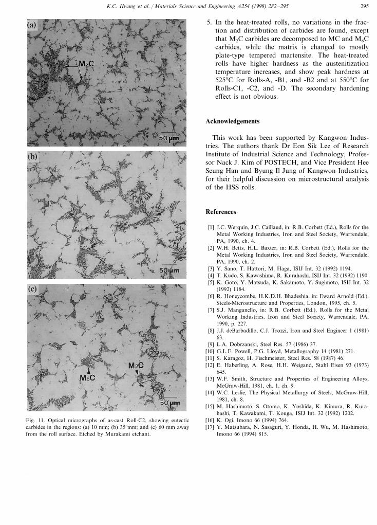
The cooling rate during casting affects the carbideformation. Fig. 11(a) through (c) are optical micro-graphs showing the changes in carbides as to the dis-tance from the surface of Roll-C2. In the surfaceregion, a number of fibrous M2C carbides are observed(Fig. 11(a)). As it gets into the interior, M6C carbidesare formed, while the fraction of M2C carbides isreduced (Fig. 11(b) and (c)). This indicates that manyM2C carbides are formed at faster cooling rate, whereasM6C carbides, together with M2C carbides, are formedat slower rate.
At a given cooling rate, the matrix characteristics arechanged depending on the composition. For instance,in the matrix of Roll-A, to which only a small amountof alloying elements is added, pearlite is formed becausethe cooling curve meets probably with the pearlite noseduring cooling. If the nose moves to the right as inRolls-B1 through -D due to the high contents of W,Mo, Cr, and V in the matrix, phase transformation tomartensite occurs readily because the cooling curvedoes not meet with the pearlite nose.
5. Conclusions
In this study, the effects of alloying elements onmicrostructure and fracture properties of six HSS rollsmanufactured by centrifugal casting method wasinvestigated.1. The as-cast HSS rolls consist of the martensitic
matrix, hard carbides such as MC, M2C, M7C3, andM6C, and fine carbides inside the matrix. The mostimportant microstructural factor among them is theintercellular carbides and their distribution.
2. Various types of carbides are formed depending onthe contents of strong carbide forming elements. InRolls-A, -B1, and -B2 containing the high Cr con-tent, MC carbides inside cells and M7C3 carbides incell boundaries are primarily formed. In Rolls-Cl,-C2, and -D containing the high W and Mo con-tents, MC carbides inside the cells and fibrous M2Ccarbides in the intercellular regions are dominantlyformed, with additional formation of M6C carbidesin Roll-D.
3. The carbon content of the matrix is 0.2–0.7%. Thematrix type is mainly lath one when the carboncontent is under 0.4%, while mainly plate one whenit is over 0.4%. Overall roll hardness tends to in-crease when the martensitic matrix is of plate-typeand as the total carbide fraction increases.
4. The effects of alloying elements are analyzed usingthe liquidus surface diagram showing the solidifica-tion process of the HSS rolls. The results of theappropriate content of each alloying element are;1.9–2.0% of carbon, 3–4% of W and Mo, respec-tively, 5–7% of Cr, and 5–6% of V.
K.C. Hwang et al. / Materials Science and Engineering A254 (1998) 282–295 295
Fig. 11. Optical micrographs of as-cast Roll-C2, showing eutecticcarbides in the regions: (a) 10 mm; (b) 35 mm; and (c) 60 mm awayfrom the roll surface. Etched by Murakami etchant.
5. In the heat-treated rolls, no variations in the frac-tion and distribution of carbides are found, exceptthat M2C carbides are decomposed to MC and M6Ccarbides, while the matrix is changed to mostlyplate-type tempered martensite. The heat-treatedrolls have higher hardness as the austenitizationtemperature increases, and show peak hardness at525°C for Rolls-A, -B1, and -B2 and at 550°C forRolls-C1, -C2, and -D. The secondary hardeningeffect is not obvious.
Acknowledgements
This work has been supported by Kangwon Indus-tries. The authors thank Dr Eon Sik Lee of ResearchInstitute of Industrial Science and Technology, Profes-sor Nack J. Kim of POSTECH, and Vice President HeeSeung Han and Byung Il Jung of Kangwon Industries,for their helpful discussion on microstructural analysisof the HSS rolls.
References
[1] J.C. Werquin, J.C. Caillaud, in: R.B. Corbett (Ed.), Rolls for theMetal Working Industries, Iron and Steel Society, Warrendale,PA, 1990, ch. 4.
[2] W.H. Betts, H.L. Baxter, in: R.B. Corbett (Ed.), Rolls for theMetal Working Industries, Iron and Steel Society, Warrendale,PA, 1990, ch. 2.
[3] Y. Sano, T. Hattori, M. Haga, ISIJ Int. 32 (1992) 1194.[4] T. Kudo, S. Kawashima, R. Kurahashi, ISIJ Int. 32 (1992) 1190.[5] K. Goto, Y. Matsuda, K. Sakamoto, Y. Sugimoto, ISIJ Int. 32
(1992) 1184.[6] R. Honeycombe, H.K.D.H. Bhadeshia, in: Eward Arnold (Ed.),
Steels-Microstructure and Properties, London, 1995, ch. 5.[7] S.J. Manganello, in: R.B. Corbett (Ed.), Rolls for the Metal
Working Industries, Iron and Steel Society, Warrendale, PA,1990, p. 227.
[8] J.J. deBarbadillo, C.J. Trozzi, Iron and Steel Engineer 1 (1981)63.
[9] L.A. Dobrzanski, Steel Res. 57 (1986) 37.[10] G.L.F. Powell, P.G. Lloyd, Metallography 14 (1981) 271.[11] S. Karagoz, H. Fischmeister, Steel Res. 58 (1987) 46.[12] E. Haberling, A. Rose, H.H. Weigand, Stahl Eisen 93 (1973)
645.[13] W.F. Smith, Structure and Properties of Engineering Alloys,
McGraw-Hill, 1981, ch. 1, ch. 9.[14] W.C. Leslie, The Physical Metallurgy of Steels, McGraw-Hill,
1981, ch. 8.[15] M. Hashimoto, S. Otomo, K. Yoshida, K. Kimura, R. Kura-
hashi, T. Kawakami, T. Kouga, ISIJ Int. 32 (1992) 1202.[16] K. Ogi, Imono 66 (1994) 764.[17] Y. Matsubara, N. Sasaguri, Y. Honda, H. Wu, M. Hashimoto,
Imono 66 (1994) 815.
.