effects of human limb gestures on galvanic coupling intra ... · generally, galvanic coupling ibc...
TRANSCRIPT

Effects of human limb gestures on galvanic coupling intra‑body communication for advanced healthcare systemXi Mei Chen1,2†, Sio Hang Pun1†, Jian Feng Zhao3*†, Peng Un Mak2†, Bo Dong Liang3† and Mang I. Vai1,2†
BackgroundThe aging population and prevalence of chronic diseases call for the deployment of remote health monitoring system [1, 2], which helps to improve the quality of patients’ life meanwhile prevents the deterioration of diseases. The healthcare monitoring data from the wearable sensors, which are limited in memory and energy, should be timely and reliably delivered to a relay node mounted on the body for further processing. The transmission technique utilized by the relay node and sensors, especially the implant-able sensors such as pacemaker should be low transmission power (energy saving) [3], low interference (avoid interference from or to other telemetry devices) and high reli-ability (avoid information leakage from eavesdropping) [4]. Compared to the existing wireless techniques (i.e. Bluetooth, Wi-Fi) which are pervasively utilized in the everyday devices (e.g. cell phone, microwave even, earphone), galvanic coupling IBC is a poten-tial candidate. As the signal in galvanic coupling IBC is confined within human body [5,
Abstract
Background: Intra-Body Communication (IBC), which utilizes the human body as the transmission medium to transmit signal, is a potential communication technique for the physiological data transfer among the sensors of remote healthcare monitoring system, in which the doctors are permitted to remotely access the healthcare data without interrupt to the patients’ daily activities.
Methods: This work investigates the effects of human limb gestures including various joint angles, hand gripping force and loading on galvanic coupling IBC channel. The experiment results show that channel gain is significantly influenced by the joint angle (i.e. gain variation 1.09–11.70 dB, p < 0.014). The extension, as well as the appearance of joint in IBC channel increases the channel attenuation. While the other gestures and muscle fatigue have negligible effect (gain variation <0.77 dB, p > 0.793) on IBC chan-nel. Moreover, the change of joint angle on human limb IBC channel causes significant variation in bit error rate (BER) performance.
Conclusions: The results reveal the dynamic behavior of galvanic coupling IBC chan-nel, and provide suggestions for practical IBC system design.
Keywords: Human limb gestures, Joint angle, Muscle fatigue, Bit error rate, Galvanic coupling intra-body communication
Open Access
© 2016 The Author(s). This article is distributed under the terms of the Creative Commons Attribution 4.0 International License (http://creativecommons.org/licenses/by/4.0/), which permits unrestricted use, distribution, and reproduction in any medium, provided you give appropriate credit to the original author(s) and the source, provide a link to the Creative Commons license, and indicate if changes were made. The Creative Commons Public Domain Dedication waiver (http://creativecommons.org/publicdo-main/zero/1.0/) applies to the data made available in this article, unless otherwise stated.
RESEARCH
Chen et al. BioMed Eng OnLine (2016) 15:60 DOI 10.1186/s12938‑016‑0192‑z BioMedical Engineering
OnLine
*Correspondence: [email protected] †Xi Mei Chen, Sio Hang Pun, Jian Feng Zhao, Peng Un Mak, Bo Dong Liang and Mang IVai contributed equally to this work3 Shenzhen Polytechnic, West Shahe Street Xili Lake, Nanshan District, Shenzhen 518000, Guangdong Province, ChinaFull list of author information is available at the end of the article

Page 2 of 15Chen et al. BioMed Eng OnLine (2016) 15:60
6], and thus it avoids signal leakage from eavesdropping and the interference to other devices. Moreover, it avoids interference from existing wireless techniques due to its low transmission frequency (i.e. <1 MHz [6, 7]). Compared to another type IBC- capacitive coupling IBC, where two ground electrodes at transceiver require floating [8], galvanic coupling IBC is less prone to environment interference due to its signal electrodes and ground electrodes at transceiver are attached on human body [6]. The floating electrodes in capacitive coupling IBC makes its implementation in implantable devices challenged. Generally, galvanic coupling IBC works in lower frequency than capacitive coupling IBC. The advantage of using low frequency carrier is minimizing the system clock [9], which can minimize the local heating and allow one to simplify the design of transceiver via low but at the expense of data rate. Fortunately, the data rate requirement for home-based healthcare data monitoring can be relatively low, e.g. 1.6 kbps in glucose moni-tor, 120 bps in body temperature surveillance and 144 kbps in ECG [10]. Therefore, the galvanic-type IBC serves as a promising choice to build the remote health monitoring system.
The remote health monitoring system permits the doctors or physicians to access the physiological data without interrupting the patients’ everyday life, in which human body executes the movement in terms of joint angle, force, torque, etc [11]. That is the human limb will move and post different gestures. However, the effects of different gestures on the communication performance of IBC channel have not been fully discussed yet. Few empirical measurements [12–15] have been conducted to investigate this issue. For instance, channel attenuation was found to be less influenced by the whole body motions such as sitting, standing and walking [16, 17]. The flexion of forearm caused channel gain in the upper limb capacitive coupling IBC channel vary around 2 dB [15]. It was found that with small transversal distance between electrodes, the performance of galvanic coupling method was more susceptible to the body composition while capacitive cou-pling method was affected by motion [13], the flexion of elbow joint (from downward to 90°) resulted in 5 dB attenuation decrease [14]. However, with large transversal distance between electrodes, wherein better attenuation results would be obtained for galvanic coupling method [16], the effects of different gestures are not yet investigated. It should be noted that the change of muscle condition such as isometric contraction (hand grip-ping force or loading) and muscle fatigue causes the change of electrical properties, i.e. electrical impedance of human arm decreases around 3–5 � due to isometric contrac-tion [18], decreases 5–20 � [18, 19] owing to muscle fatigue [20], however, their effects on IBC channel have not yet been addressed. Moreover, the reliability of communication performance (i.e. BER) during dynamic behavior of human body is not discussed yet.
Consequently, in order to provide suggestions for galvanic coupling IBC system design, the effects on channel communication performance from different body gestures and muscle conditions are investigated. Although better channel gain was achieved in trunk and back for galvanic coupling method [16], however, the human limb channels will be investigated. Since the relay nodes, such as smart-watch or smart wristband [21, 22] are usually mounted on the human extremities. Specifically, the effects on human limb gal-vanic coupling IBC channels from different gestures, such as various joint angles, hand gripping force and hand loading, and muscle fatigue are yet to be studied. And the in-depth analysis of the effects on BER performance will be to conducted.

Page 3 of 15Chen et al. BioMed Eng OnLine (2016) 15:60
The signal propagation in galvanic coupling IBC channel can be characterized by the channel frequency response H(f) [23], which can be described as:
where f is operating frequency, Vout(f ) and Vin(f ) are the output signal and input sig-nal, respectively. θ (f ) is the phase, and |H(f)| is the magnitude of frequency response. In what follows, the experimental designs to measure the frequency response are pre-sented. Then the experiment results and discussions are provided. Finally, the conclu-sions are provided.
MethodsExperiment setup
Two experiment setups, shown in Figs. 1 and 2, were implemented for the purpose of studying the effects on galvanic coupling IBC channel from different limb gestures and muscle fatigue. For both experiments, the frequency response, which includes gain (|H(f )|2) in dB and phase (θ (f )) in degree, in sub-MHz frequency band was measured by a network analyzer (Agilent, 4395A). The sub-MHz frequency band is utilized as it can make the electric field confined within the human body [5], similar settings were adopted in other reports [7, 16, 24]. During measurements, the chirp signal from net-work analyzer was applied on the human limb by a pair of skin-attached stimulating electrodes (Shenzhen Jurongda Science and Technology Ltd., Carbon 20 × 20 mm), and detected by another pair of electrodes via a differential probe (Agilent, 1141A) that was used for breaking the ground loop of measurement equipment. For satisfactory received signal level, the vertical distance of the two pair of electrodes (channel length) was set to 10 cm. For the first experiment, as shown in Fig. 1, the measurements were performed
(1)H(f ) =Vout(f )
Vin(f )= |H(f )|ejθ(f )
Fig. 1 Experiment setup to investigate the effects of limb gestures on galvanic coupling IBC channel. For upper extremity channels (A1A2 and A1A3), the frequency response at each joint angle is measured with empty-handed, gripping force and loading. For lower extremity channels (B1B2 and B1B3), it is measured with the change of knee joint angles

Page 4 of 15Chen et al. BioMed Eng OnLine (2016) 15:60
on the upper and lower extremity channels including upper arm channel (A1A2), chan-nel through elbow joint (A1A3), thigh channel (B1B2) and channel through knee joint (B1B3). For the upper extremity channels, different elbow joint angles (i.e. 180, 135, 90 and 45°) and hand conditions (i.e. empty-handed, loading with dumbbell and gripping a force transducer) were considered. For the lower extremity, different knee joint angles (i.e. 180, 135 and 90°) were evaluated. For the second experiment, as depicted in Fig. 2, wherein the measurements of frequency response and electromyography (EMG) of biceps [25, 26] were carried out on the upper arm. And the EMG was recorded by a bio-amplifier (NI instrument, PowerLab 15T) for further analysis.
To prevent the movement of upper arm or thigh and at the same time maintain stable joint angle, a plastic rod (length: 1.2 m, diameter: 19 mm) sticking with a joint fixation apparatus (Hengshui Jingyuan Medical Apparatus and Instruments Ltd., Joint type med-ical external fixation support) was fabricated and shown in Fig. 3. The rod was stucken to the heavy desk by glue and meanwhile fasten by strape. Then the upper part of appa-ratus was vertically secured to the rod by glue and strape, the lower part was left for angle adjusting. Once the angle achieved, the rotation axis of apparatus was fasten by screws to avoid changing. During the measurement on upper extremity channels, the subject was ask to sit in chair with thigh horizontal, right upper arm leant on the rod and downward vertically against the rod. By adjusting the height of chair, the elbow joint was visually aligned with the rotation axis of apparatus. Then the upper arm was securely fastened to the rod, and the lower arm was fasten to lower part of apparatus via strape. Consequently, the upper arm could not swing or move, meanwhile the joint angle was sustained. Similarly, for the lower extremity, the subject stand and the thigh was fastened to the rod.
Fig. 2 Experiment setup to investigate the effects of muscle fatigue on galvanic coupling IBC channel. With hand loading 2.5 kg dumbbell and elbow joint flexing to 45°, the EMG of biceps and frequency response of A1A2 are measured

Page 5 of 15Chen et al. BioMed Eng OnLine (2016) 15:60
Experiment protocol
Four volunteers, ranging from 23 to 33 years of age participated in the study. All subjects were healthy and had no known neuromuscular or joint muscle disorders at the time of the study. All subjects were gave informed consent the procedures approved by the Institutional Review Board of Medical Center Institutional, Shenzhen Polytechnic. The measurement parameters are summarized in Table 1. The anthropometrical characteris-tics of the subjects including the body mass index (BMI) are presented in Table 2. After the experiment setup, the subject performed ten trails of joint contraction and extension with joint angle changes from approximately 180–90 or 45°. With a 1 min rest, the sub-ject got into the first experiment session: limb gesture effect experiment.
Fig. 3 Experiment setup to avoid the movement of upper arm or thigh. For channels A1A2 and A1A3, the setup is adapted to avoid the movement of upper arm, while for B1B2 and B1B3, the movement of thigh is avoided
Table 1 The measurement parameters
Parameters Value
Test subjects Two males and two females
Signal transmission power 0 dBm
Frequency range 1 kHz–1 MHz
Electrodes Stimulating electrodes (carbon)
Transverse distance between electrodes Circular symmetry: 6–12 cm (upper limbs), 11–20 cm (lower limbs)
Transmission distance 10 cm

Page 6 of 15Chen et al. BioMed Eng OnLine (2016) 15:60
Limb gesture effect experiment
The experiment setup is presented in Fig. 1, and the subject was instructed not to move. The frequency response of channel A1A2 with joint angle 180° was measured by the cali-brated network analyzer with empty-handed, loading with 0.5 and 2.5 kg mass (dumb-bell), gripping force of 0.5 and 2.5 kg. With each case, the subject held the gesture for 10 s to make sure the channel frequency response was steady for capture. So is the case with 135, 90 and 45°. Similarly, the experiments were performed on channel A1A3.
Finishing the measurement on upper extremity, the setup was changed to the lower extremity. Due to the limited motion of range in leg, three knee joint angles (180, 90 and 15°) are considered. After the limb gesture measurement, the subject got into the second experiment session: muscle fatigue effect experiment.
Muscle fatigue effect experiment
The experiment setup is shown in Fig. 2. From our empirical experiment, the human limb feels fatigue in 1 min when the hand is loading a 2.5 kg dumbbell. Consequently, the EMG of upper arm was recorded for 1 minute via the bio-amplifier with hand loading 2.5 kg dumbbell and elbow joint maintaining at 45°. Then the frequency response was captured at different recording time, for instance at 2, 30 and 58 s.
Statistic method and signal processing
According to our empirical experiments (up to 23 subjects), the gain or phase follows approximately normal distribution among the subjects. Additionally, more than two groups of measurements were conducted for each effect. Consequently, one-way analy-sis of variance (ANOVA) with F test [27] was adopted to examine the significance of different gestures’ effects. The F statistic is calculated by dividing the mean square of the between-groups variance by the mean square of the within-groups variance. Then p value can be calculated from the F distribution based on the specific F statistic and the number of groups and observations.
To analyze the effects of channel variations on communication performance, the change of BER for some typical modulation schemes, such as quadrature phase shift key-ing (QPSK), 16-ary quadrature amplitude modulation (16QAM) and 16-ary frequency shift keying (16FSK) [28] was calculated. Assuming that the noise in IBC channel, which is mainly from the thermal noise of electronic devices and electrode-skin interface, is additive white Gaussian noise (AWGN) [24], the BER of the modulation methods is described as:
(2)PbQPSK = Q (√
2γb)
Table 2 The anthropometrical characteristics of subjects
a Represents female
Subjects Age BMI Upper arm length (cm)
Upper arm diameter (cm)
Thigh length (cm)
Thigh diameter (cm)
S1a 33 18.1 20 6 35 11
S2 23 20.0 25 8 40 14
S3 26 23.2 25 9 41 16
S4a 25 26.3 22 12 35 20

Page 7 of 15Chen et al. BioMed Eng OnLine (2016) 15:60
where Pb is the BER, Q is the Q-function [24]. γb is signal to noise ratio per bit, which is proportional to channel gain. With a BER of 10−6, the required γb is 10.5, 14.5 and 8.4 dB for QPSK, 16QAM and 16FSK, respectively. With the change of channel gain, the γb will change, and thus BER will vary (e.g. channel gain attenuates 3 dB, γb decreases 3 dB, BER
increases from Q (√2γb) to Q (
√
2× 10⁻³
10 γb) for QPSK).
Results and discussionsResults
The frequency response of galvanic coupling IBC channel affected by joint angle and muscle fatigue is depicted in this section. For the sake of repeatability, the measurements were carried out over 3 days, and the variations are calculated. To demonstrate the inter-subjects difference, the results at two angles (i.e. at 180 and 90°) from angle effect for dif-ferent subjects are displayed. For sake of comparison among different effects, the mean of gain and phase over 3 days’ measurements influenced by joint angle, hand gripping force and loading are displayed in a table. The variations of BER performance due to extension of joint angle among the subjects are presented.
Effects of joint angle
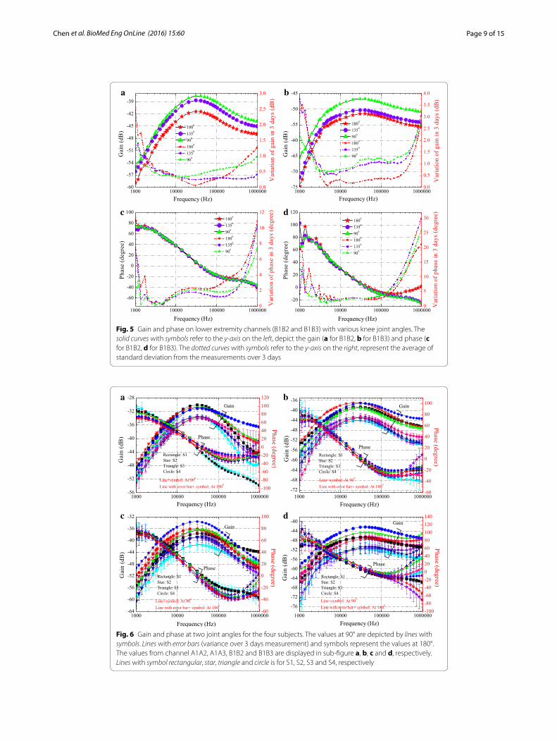
The gain and phase on upper and lower extremity channels affected by joint angle (for subject 1) are shown in Figs. 4 and 5, respectively. The results reveal that there is a strong dependence between channel gain and joint angle, and generally the gain increases as the joint angle decreases. A bandpass profile with passband from 20 to 100 kHz is observed and peak is found at frequency around 20 kHz. Compared to Fig. 4a, more obvious gain increase is observed in Fig. 4b due to the decrease of angle, and more significant gain increase occurs at small joint angle positions (i.e. from 135 to 90° and from 90 to 45°). Similarly, in lower extremity channels, the gain is significantly increased at small angle position (from 135 to 90°) for Fig. 5b. It is noticed that the phase is less influenced by the joint angle. As shown in Figs. 4c and 5c, the phase curves is almost indistinguishable for various joint angles. For channels through the joint, the phase (illustrated in Figs. 4d, 5d) is just distinguishable in the relatively high frequency (i.e. higher than 200 kHz).
Variation on different days
The standard deviation (square root of the variance) over 3 days for subject 1 are included in Figs. 4 and 5. From the 3 days’ measurement results, the standard deviation of gain is lower than 3 dB, phase variation is lower than 22° for upper extremity chan-nels. For lower extremity channels, the gain variation is lower than 4 dB, phase variation is lower than 30°. More noticeable variation is found in the low frequency (i.e. lower than 4 kHz) and high frequency regions (i.e. higher than 200 kHz). This could be explained by the fact that, the low frequency components are more prone to the environmental inter-ference (i.e. noise, voice), while the high frequency components are affected by some parasitic capacitance (i.e. electrode-skin parasitic capacitance).
(3)Pb16QAM = Q (√
0.8γb)
(4)Pb16FSK = 15Q(√
4γb)

Page 8 of 15Chen et al. BioMed Eng OnLine (2016) 15:60
Different channels
Comparing Fig. 4a and b, with the same transmission distance 10 cm, the gain is lower in Fig. 4b, which means the appearance of elbow joint in IBC channel leads to an additional channel attenuation around 5 dB (at 45°) to even 10 dB (at 180°). For the lower extrem-ity case, more than 3 dB is suffered from the the knee joint. Similar results are reported in [14]. This is mainly due to the large area of bone and seldom muscle in joint, which hinders the electric field penetration and electric current transfer.
With the same distance, for the channels without joint (A1A2 and B1B2) or with joint (A1A3 and B1B3), the lower extremity channel suffers from higher attenuation.
Different subjects
To demonstrate the inter-subjects difference, the gain and phase at two joint angles (90 and 180°) from the four subjects are shown in Fig. 6. With smaller joint angle, the gain is higher. The gains for different subjects are showed similar trends with variations lower than 5 dB when frequency lower than 200 kHz, larger variations are generally in the higher frequency regions (around 1 MHz). Higher gain is obtained for subject four (S4). This could be due to the larger diameter of limbs, similar results have also been reported by other authors [16].
a b
c d
Fig. 4 Gain and phase on upper extremity channels (A1A2 and A1A3) with various elbow joint angles. The solid curves with symbols refer to the y-axis on the left, depict the gain (a for A1A2, b for A1A3) and phase (c for A1A2, d for A1A3). The dotted curves with symbols refer to the y-axis on the right, represent the average of standard deviation from the measurements over 3 days
Page 9 of 15Chen et al. BioMed Eng OnLine (2016) 15:60
a b
c d
Fig. 5 Gain and phase on lower extremity channels (B1B2 and B1B3) with various knee joint angles. The solid curves with symbols refer to the y-axis on the left, depict the gain (a for B1B2, b for B1B3) and phase (c for B1B2, d for B1B3). The dotted curves with symbols refer to the y-axis on the right, represent the average of standard deviation from the measurements over 3 days
a b
c d
Fig. 6 Gain and phase at two joint angles for the four subjects. The values at 90° are depicted by lines with symbols. Lines with error bars (variance over 3 days measurement) and symbols represent the values at 180°. The values from channel A1A2, A1A3, B1B2 and B1B3 are displayed in sub-figure a, b, c and d, respectively. Lines with symbol rectangular, star, triangle and circle is for S1, S2, S3 and S4, respectively

Page 10 of 15Chen et al. BioMed Eng OnLine (2016) 15:60
Effects of loading, gripping force and muscle fatigue
The influence of muscle fatigue is shown in Fig. 7. The MNF of the EMG decreases from 120 to 90 Hz, which indicates the muscle is in the process of fatigue. While the gain and phase captured at different time is almost indistinguishable, which suggests that muscle fatigue has negligible effect on the IBC channel.
For hand loading and gripping force, their influence is small and the value will be shown in next section.
Comparison of different gestures
The effects of the three gestures on upper extremity channels from the four subjects are shown in Table 3. For joint angle effect, by using the baseline value with elbow joint angle 180°, deviation in gain and phase at 20 kHz for other joint angles (at 135, 90 and 45°) are calculated. For gripping force and loading (0.5 and 2.5 kg), baseline value of empty-handed is referred. Note that these values are the average of the three days’ measurements.
The p values of F test for the three effects are also included in Table 3. During the calculation, the gain and phase at 20 kHz serve as the data in observations. The number of groups is 4 (four joint angles), 12 (0, 0.5 and 2.5 kg at each angle) and 12 for angle effect, gripping force effect and loading effect, respectively. The respective number of observations is 16, 48 and 48. The p values smaller than 0.05 are considered statistically significant.
For joint angle effect, the trends from the four subjects are similar, that is the smaller the joint angle, the larger the gain variation. The change of joint angle causes great vari-ations on channel gain, i.e., gain variation larger than 3.75 and 8.11 dB at 45° for A1A2 and A1A3, respectively. The joint angle factor has significant effect on gain (p < 0.014 for A1A2, p < 0.001 for A1A3). For gripping force and loading, their effects are small, i.e. gain variation smaller than 0.77 dB (p > 0.793), phase variation lower than 4° (p > 0.836), and can be ignored.
Fig. 7 Muscle fatigue effect on IBC channel. In the subfigure with double y-axis, the gain is depicted by solid curves with symbols, while phase is depicted by dotted curves

Page 11 of 15Chen et al. BioMed Eng OnLine (2016) 15:60
Variation of bit error rate
For human limb IBC channels, the worse channel condition (lowest gain) occurs when the joint extends to position 180°. While best channel condition is obtained when joint flexes, i.e. to position 45° for upper extremity channels, 90° for lower extremity channels. With joint’s flexion and extension, the channel suffers from unstable channel conditions, which will cause the communication performance (i.e. BER) to vary.
Assuming that BER is 10−6 when channel is at best channel condition (at 45° for A1A2 and A1A3, at 90° for B1B2 and B1B3), BERs at worse channel conditions for the four subjects are displayed in Table 4. The results show that in subject 1 (S1), in worse case, BER of QPSK degrades to 1.0 × 10⁻³ and 5.7 × 10⁻² for A1A2 and A1A3 respectively. And the degradation is less significant for lower extremity channels. It can be noticed that the flexion and extension of elbow joint causes a one ( 1.5 × 10⁻⁵–1.0 × 10⁻⁶) to five (1.0 × 10⁻¹–1.0 × 10⁻⁶) orders of magnitude variation in BER of QPSK for upper extremity channels, while for lower extremity channels, the variation is over one (1.2 × 10⁻⁵–1.0 × 10⁻⁶) to three (9.3 × 10⁻³–1.0 × 10⁻⁶) orders of magnitude due to the change of knee joint angle.
Among the three modulation schemes, 16FSK is most susceptible to the influence of joint angle (largest BER variation). QPSK and 16QAM obtains almost the same BER per-formance variation.
Table 3 Standard deviations and p values on gain and phase at 20 kHz for upper extremity IBC channels from different effects
Effect on subjects Joint angle effect Gripping force effect Loading effect
At 135° At 90° At 45° 0.5 kg 2.5 kg 0.5 kg 2.5 kg
Upper arm channel (A1A2)
S1 Gain (dB) 1.27 3.11 3.75 0.17 0.18 0.11 0.21
Phase (degree) 1.42 2.85 2.16 2.65 2.41 0.55 0.97
S2 Gain (dB) 1.97 3.44 4.09 0.11 0.11 0.08 0.15
Phase (degree) 1.15 1.97 3.21 0.82 0.79 0.30 0.69
S3 Gain (dB) 1.51 3.79 4.49 0.15 0.17 0.49 0.30
Phase (degree) 1.25 2.14 3.24 0.25 0.28 0.64 0.97
S4 Gain (dB) 2.00 3.68 4.96 0.33 0.77 0.10 0.63
Phase (degree) 2.21 2.91 2.10 0.83 0.68 0.41 0.54
p value On gain 0.014 0.826 0.793
On phase 0.946 0.991 0.992
Channel through the joint (A1A3)
S1 Gain (dB) 3.89 6.24 9.56 0.35 0.38 0.76 0.53
Phase (degree) 4.62 3.38 6.94 2.29 2.65 1.93 1.81
S2 Gain (dB) 3.20 7.46 11.70 0.47 0.38 0.33 0.43
Phase (degree) 2.11 4.97 9.22 1.83 2.11 1.25 2.20
S3 Gain (dB) 1.09 4.36 8.11 0.19 0.36 0.26 0.13
Phase (degree) 1.81 3.41 7.09 0.90 1.13 1.92 1.35
S4 Gain (dB) 1.34 5.68 10.51 0.26 0.24 0.30 0.68
Phase (degree) 3.25 6.48 11.35 3.65 3.66 0.90 1.05
p value On gain 0.001 0.904 0.987
On phase 0.899 0.836 0.913

Page 12 of 15Chen et al. BioMed Eng OnLine (2016) 15:60
Table 4 BER performance of modulation schemes with joint extending to different posi-tions (for upper limb channels, BER is 10−6 with elbow joint at 45°, for lower limb channels, BER is 10−6 with knee joint at 90°)
Subjects A1A2 B1B2
To 90° To 135° To 180° To 135° To 180°
QPSK
S1 2.1 × 10⁻⁵ 4.6 × 10⁻⁴ 1.0 × 10⁻³ 1.2 × 10⁻⁵ 1.0 × 10⁻⁴
S2 7.9 × 10⁻⁵ 7.1 × 10⁻⁴ 1.5 × 10⁻³ 4.7 × 10⁻⁵ 1.3 × 10⁻⁴
S3 3.4 × 10⁻⁵ 1.0 × 10⁻³ 2.3 × 10⁻³ 4.9 × 10⁻⁵ 3.0 × 10⁻⁴
S4 8.3 × 10⁻⁵ 9.6 × 10⁻⁴ 3.7 × 10⁻³ 1.9 × 10⁻⁵ 1.6 × 10⁻⁴
Subjects A1A3 B1B3
To 90° To 135° To 180° To 135° To 180°
S1 1.2 × 10⁻³ 1.0 × 10⁻² 5.7 × 10⁻² 6.8 × 10⁻⁴ 3.6 × 10⁻³
S2 5.2 × 10⁻⁴ 2.2 × 10⁻² 1.0 × 10⁻¹ 3.0 × 10⁻⁴ 1.3 × 10⁻³
S3 1.5 × 10⁻⁵ 2.1 × 10⁻³ 3.1 × 10⁻² 2.0 × 10⁻³ 9.3 × 10⁻³
S4 2.4 × 10⁻⁵ 6.8 × 10⁻³ 7.9 × 10⁻² 4.7 × 10⁻⁴ 1.4 × 10⁻³
Subjects A1A2 B1B2
To 90° To 135° To 180° To 135° To 180°
16QAM
S1 2.0 × 10⁻⁵ 4.5 × 10⁻⁴ 1.0 × 10⁻³ 1.2 × 10⁻⁵ 1.0 × 10⁻⁴
S2 7.7 × 10⁻⁵ 7.0 × 10⁻⁴ 1.5 × 10⁻³ 4.6 × 10⁻⁵ 1.3 × 10⁻⁴
S3 3.3 × 10⁻⁵ 1.1 × 10⁻³ 2.3 × 10⁻³ 4.7 × 10⁻⁵ 3.0 × 10⁻⁴
S4 8.1 × 10⁻⁵ 9.4 × 10⁻⁴ 3.6 × 10⁻³ 1.8 × 10⁻⁵ 1.6 × 10⁻⁴
Subjects A1A3 B1B3
To 90° To 135° To 180° To 135° To 180°
S1 1.2 × 10⁻³ 1.0 × 10⁻² 5.7 × 10⁻² 6.7 × 10⁻⁴ 3.6 × 10⁻³
S2 5.1 × 10⁻⁴ 2.2 × 10⁻² 1.1 × 10⁻¹ 3.0 × 10⁻⁴ 1.3 × 10⁻³
S3 1.4 × 10⁻⁵ 2.0 × 10⁻³ 3.1 × 10⁻² 1.9 × 10⁻³ 9.2 × 10⁻³
S4 2.4 × 10⁻⁵ 6.8 × 10⁻³ 7.8 × 10⁻² 4.6 × 10⁻⁴ 1.4 × 10⁻³
Subjects A1A2 B1B2
To 90° To 135° To 180° To 135° To 180°
16FSK
S1 4.1 × 10⁻⁵ 1.8 × 10⁻³ 4.7 × 10⁻³ 2.1 × 10⁻⁵ 2.9 × 10⁻⁴
S2 2.1 × 10⁻⁴ 3.0 × 10⁻³ 7.6 × 10⁻³ 1.1 × 10⁻⁴ 4.1 × 10⁻⁴
S3 7.4 × 10⁻⁵ 5.0 × 10⁻³ 1.3 × 10⁻² 1.1 × 10⁻⁴ 1.1 × 10⁻³
S4 2.2 × 10⁻⁴ 4.3 × 10⁻³ 2.2 × 10⁻² 3.5 × 10⁻⁵ 4.8 × 10⁻⁴
Subjects A1A3 B1B3
To 90° To 135° To 180° To 135° To 180°
S1 5.8 × 10⁻³ 7.7 × 10⁻² 6.1 × 10⁻¹ 2.8 × 10⁻³ 2.2 × 10⁻²
S2 2.0 × 10⁻³ 1.9 × 10⁻¹ 1.28 1.1 × 10⁻³ 6.4 × 10⁻³
S3 2.6 × 10⁻⁵ 1.1 × 10⁻² 2.9 × 10⁻¹ 1.0 × 10⁻² 6.7 × 10⁻²
S4 4.9 × 10⁻⁵ 4.7 × 10⁻² 8.8 × 10⁻¹ 1.8 × 10⁻³ 6.8 × 10⁻³

Page 13 of 15Chen et al. BioMed Eng OnLine (2016) 15:60
Discussion
Different effects
Now we have a brief summary, the flexion of elbow joint angle significantly affects chan-nel gain (p < 0.014). The larger the joint extends, the higher the channel attenuates. The channel remains almost the same for gestures of empty-handed, loading and gripping force. These phenomenons can be explained by the fact that in galvanic coupling IBC channel, the majority of electric current is conveyed by muscle tissue (larger than 90 % for frequency lower than 1 MHz) [6]. When the elbow joint flexes (angle decrease), the muscle performs the concentric contraction, in which the length of muscle is shorten significantly [29], and thus results in lower channel attenuation (shorter channel length). While for hand loading or gripping force, the muscle undergoes the isometric contrac-tion, wherein the reduction of muscle length is negligible [29, 30], and thus it leads to small changes of channel attenuation.
The findings suggest that in case of body movement without changing joint angle, the gain will be the same for different gestures. That explains why the gain of arm channels is approximately the same for the three positions of sitting, standing and walking in [16].
Practical hints for system design
For different gestures or moving conditions, the suitable frequency range for data trans-mission remains the same, that is from 20 to 100 kHz. Among the three modulation methods, QPSK is suitable for data transmission, since its high power efficiency [28] and relatively low BER variation. In worst case, the BER in upper limb channels will variate in five orders of magnitude for patient’s daily activity with joint angle changes. There-fore, to achieve the low power transmission and stable communication performance, the adaptive power control is required.
ConclusionThe experiments to evaluate the effect of human limb gestures on galvanic coupling IBC channel have been carried out in this work. The hand loading, gripping force, as well as muscle fatigue has negligible effect on human limb IBC channel. While the joint has significant effect on channel gain. The channel suffers from highest attenuation when the joint extends to 180°, and obtains best channel condition when joint flexes to 45° for the upper extremity, 90° for the lower extremity. It can be concluded that the gain variation is mainly due to the change of joint angle, which suggests that the change of gain dur-ing body movement is mainly from the change of joint angle. In case of body movement without changing joint angle, the gain will be the same for different gestures. For various gestures, the suitable frequency band for data transmission is from 20 kHz to around 100 kHz. The gain variation causes significant BER variation in modulation schemes, which suggests that to enable power saving and stable communication performance, adaptive power control is recommended.
Authors’ contributionsXMC designed and carried out the experiments, analyzed the data, and drafted the manuscript. SHP helped to draft the manuscript, explored the objective of the study. JFZ conceived the study and handled the acquisition of funding. PUM analyzed the data and drafted part of the manuscript. BDL helped to collect the data, handled the acquisition of funding. MIV conceived the study, handled the acquisition of funding and justified authorship. All authors read and approved the final manuscript.

Page 14 of 15Chen et al. BioMed Eng OnLine (2016) 15:60
Author details1 State Key Laboratory of Analog and Mixed-Signal VLSI, University of Macau, Avenida da Universidade, Taipa, Macau, China. 2 Electrical and Computer Engineering, University of Macau, Avenida da Universidade, Taipa, Macau, China. 3 Shen-zhen Polytechnic, West Shahe Street Xili Lake, Nanshan District, Shenzhen 518000, Guangdong Province, China.
AcknowledgementsThe authors would like to thank the financial support from The Science and Technology Development Fund of Macau (FDCT) under Grants 063/2009/A, 024/2009/A1, 087/2012/A3, and 047/2013/A2; The Research Committee of the University of Macau under Grants RG072/09-10S/MPU/FST, MYRG076(Y1-L2)-FST12-MPU, MYRG2014-00010-AMSV, MYRG079(Y1-L2)-FST12-VMI, MYRG103(Y1-L3)-FST13-VMI, and MRG014/MPU/2014/FST; The Fundamental Research Fund of the Shenzhen Polytechnic with Grant 601522k30007; Guangdong Provincial Science and Technology Plan projects with Grant 2016A010101039.
Competing interestsThe authors declare that they have no competing interests.
Received: 22 October 2015 Accepted: 16 May 2016
References 1. Benhaddou D, Balakrishnan M, Yuan X. Remote healthcare monitoring system architecture using sensor networks.
In: IEEE region 5 conference.Kansas City: IEEE; 2008. p. 1–6. 2. Kirbas I, Bayilmis C. Healthface: a web-based remote monitoring interface for medical healthcare systems based on
a wireless body area sensor network. J Elec Eng Comput Sci. 2012;20(4):629–38. 3. Bazaka K, Jacob MV. Implantable devices: issues and challenges. Electronics. 2012;2(1):1–34. 4. Halperin D, Kohno T, Heydt-Benjamin TS, Fu K, Maisel WH. Security and privacy for implantable medical devices. IEEE
Pervasive Comput. 2008;7(1):30–9. 5. Pun SH. 2011. Electromagnetic sub-MHz modeling of multilayer human limb for the galvanic coupling type intra-
body communication. Ph. D. thesis. 6. Callejon M, Reina-Tosina J, Naranjo D, Roa L. Galvanic coupling transmission in intrabody communication: a finite
element approach. IEEE Trans Biomed Eng. 2014;61(3):775–83. 7. Pun S, Gao Y, Mak P, Vai M, Du M. Quasi-static modeling of human limb for intra-body communications with experi-
ments. IEEE Trans Inf Technol Biomed. 2011;56(6):870–6. 8. Zimmerman TG. 1995. Personal area networks (pan) : near-field intra-body communication. Master thesis. 9. Liu D, Svensson C. Power consumption estimation in cmos vlsi chips. IEEE J Solid-State Circuits. 1994;29(6):663–70. 10. Chakraborty C, Gupta B, Ghosh SK. A review on telemedicine-based wban framework for patient monitoring.
Telemed J E Health. 2013;19(8):619–26. 11. Feldman AG, Levin MF. The origin and use of positional frames of reference in motor control. Behav Brain Sci.
1995;18(4):723–44. 12. Seyedi M, Lai DT, Faulkner M. Limb joint effects on signal transmission in capacitive coupled intra-body communi-
cation systems. In: 34th annual international conference of the IEEE Engineering in Medicine and Biology Society (EMBS). California: IEEE. 2012. p. 6699–702.
13. Seyedi M, Kibret B, Lai DT, Faulkner M. An empirical comparison of limb joint effects on capacitive and galvanic cou-pled intra-body communications. 2013 IEEE eighth international conference on intelligent sensors, sensor networks and information processing. Melbourne: IEEE; 2013. p. 213–8.
14. Seyedi M, Lai DTH. Effect of limb joints and limb movement on intrabody communications for body area network applications. J Med Biol Eng. 2014;34(3):276–83.
15. Vasic, Z.L., Krois, I., Cifrek, M.: Effect of body positions and movements in a capacitive intrabody communication channel from 100 kHz to 100 MHz. In: 2012 IEEE International instrumentation and measurement technology con-ference. Graz: IEEE. 2012. p. 2791–5.
16. Callejon MA, Naranjo-Hernandez D, Reina-Tosina J, Roa LM. A comprehensive study into intrabody communication measurements. IEEE Trans Instrum Meas. 2013;62(9):2446–55.
17. Nie Z, Ma J, Li Z, Chen H, Wang L. Dynamic propagation channel characterization and modeling for human body communication. Sensors. 2012;12(12):17569–87.
18. Orth T. 2013. Impedance changes in biceps brachii due to isometric contractions and muscle fatigue using electri-cal impedance myography (EIM). Ph. D. thesis.
19. Ikai, T., Saigou, R., Kyoso, M., Ishijima, M.: Dynamic electrical characteristics of the muscle with the fatigue during exercise. In: World congress on medical physics and biomedical engineering. Seoul: Springer; 2006. p. 622–5.
20. Mamaghani Koleini, Shimomura Y, Iwanaga K, Katsuura T. Changes in surface emg and acoustic myogram param-eters during static fatiguing contractions until exhaustion: influence of elbow joint angles. J Physiol Anthropol Appl Human Sci. 2001;20(2):131–40.
21. Bieber G, Haescher M, Vahl M. Sensor requirements for activity recognition on smart watches. In: the 6th interna-tional conference on pervasive technologies related to sssistive environments. New York: ACM; 2013. p. 67–16.
22. Zhang Z. Photoplethysmography-based heart rate monitoring in physical activities via joint sparse spectrum recon-struction. IEEE Trans Biomed Eng. 2015;62(8):1902–10.
23. Hsu H. Schaum’s outline of signals and systems. New York: McGraw Hill Professional; 1995. 24. Wegmueller MS. 2007. Intra-body communication for biomedical sensor networks. Ph. D. thesis.

Page 15 of 15Chen et al. BioMed Eng OnLine (2016) 15:60
• We accept pre-submission inquiries
• Our selector tool helps you to find the most relevant journal
• We provide round the clock customer support
• Convenient online submission
• Thorough peer review
• Inclusion in PubMed and all major indexing services
• Maximum visibility for your research
Submit your manuscript atwww.biomedcentral.com/submit
Submit your next manuscript to BioMed Central and we will help you at every step:
25. Thongpanja S, Phinyomark A, Limsakul C, Phukpattaranont P. Application of mean and median frequency methods for identification of human joint angles using EMG signal. In: Kim KJ, editor. Information science and applications. Berlin: Springer; 2015. p. 689–96.
26. Stirn I, Jarm T, Strojnik V. Evaluation of the mean power frequency of the emg signal power spectrum at endurance levels during fatiguing isometric muscle contractions. Kinesiologia Slovenica. 2008;14(1):28–38.
27. Tronstad C, Pripp AH. Statistical methods for bioimpedance analysis. J Electr Bioimpedance. 2014;5(1):14–27. 28. Rappaport TS. Wireless communications: principles and practice. 2nd ed. New Jersey, USA: Prentice Hall; 2002. 29. Oatis CA. 4. Biomechanics of skeletal muscle. In: Lupash EJ, Klingler AM, Glover SA, editors. Kinesiology: the mechan-
ics and pathomechanics of human movement, 2nd edn. New York: Lippincott Williams & Wilkins. 2004. p. 44–66. 30. Mann MD. Muscle contraction. In: the nervous system in action. http://www.unmc.edu/physiology/Mann/mann8.
html. Accessed 04 Mar 2016.