effects of phase noise and signal to noise ratio in pam4 ... · high level view of overall...
TRANSCRIPT

Effects of Phase Noise and Signal to Noise Ratio in PAM4 Signaling
Don PakbazJohn Austin

Introduction
Finding issues in a design is costly to schedule, and complex IPs such as HSS usingPAM4 signaling are becoming more common on designs.
Need a way to evaluate measured phase noise and/or channel signal to noise ratioand its effect on PAM4 signaling at the early stage of design engagement.
Agenda
Effect of Serial Link PLL and Clock Data Recovery (CDR).
Overview of PAM4 signaling modeled to evaluate the effect of phase noise
High level view of overall simulation setup. Modeled in using Matlab Simulink,Communication tool box, RF Tool Box and DSP toolbox.
5 different examples of “What if Scenarios” using phase noise and WhiteGaussian noise “Signal to Noise Ratio (SNR)”.
Don Pakbaz / John Austin 2

Peaking 6.4 dB
-3 dB at 1.8 Mhz
_ 25.822 13
3.766 6 5.822 13HSS PLLeTF
s e s e
HSS PLL Model
Don Pakbaz / John Austin 3

-3 dB at 4 Mhz
CDR Model
2.513 7CDRsTF s e
Don Pakbaz / John Austin 4
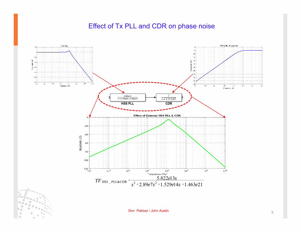
_ & 3 25.822 13
2.89 7 1.529 14 1.463 21HSS PLL CDRe sTF
s e s e s e
Don Pakbaz / John Austin 5
Effect of Tx PLL and CDR on phase noise

Measured RefClk phase noise
phase Noisespec
Effect of TX PLLand CDR
Measured phase noiseafter the effect of TX PLL
and CDR
Don Pakbaz / John Austin 6
Effect of Tx PLL and CDR on phase noise continued….

Don Pakbaz / John Austin 7
Adding the effect of PLL loop multiplier to phase noise
Effect of TX PLLand CDR
phase Noisespec
Measured RefClk phase noise
Measured phase noiseafter the effect of TX PLL
and CDR
Measured RefClk phase noise with added
PLL Loop multiplier effect

Don Pakbaz / John Austin 8
Calculating Rj and Dj (Carrier = VCO = 14 Ghz)
Rj = 57.5 fs
2.1000e+03 -1.2750e+02 1.9176e-176.0300e+03 -1.2400e+02 2.8691e-173.9150e+05 -8.2280e+01 3.4975e-155.0100e+05 -1.0420e+02 2.8038e-167.8200e+05 -8.5960e+01 2.2896e-151.2120e+06 -9.6290e+01 6.9703e-161.5860e+06 -1.0580e+02 2.3321e-161.9530e+06 -1.0930e+02 1.5587e-161.2500e+07 -1.4100e+02 4.0528e-184.2500e+08 -1.3890e+02 5.1612e-18
Freq(Hz) dBc Dj(sec)
Dominant Spur
2 2..................1.9176 17 5 s4.1612 .26f18e e Total Dj =
Don Pakbaz / John Austin 9

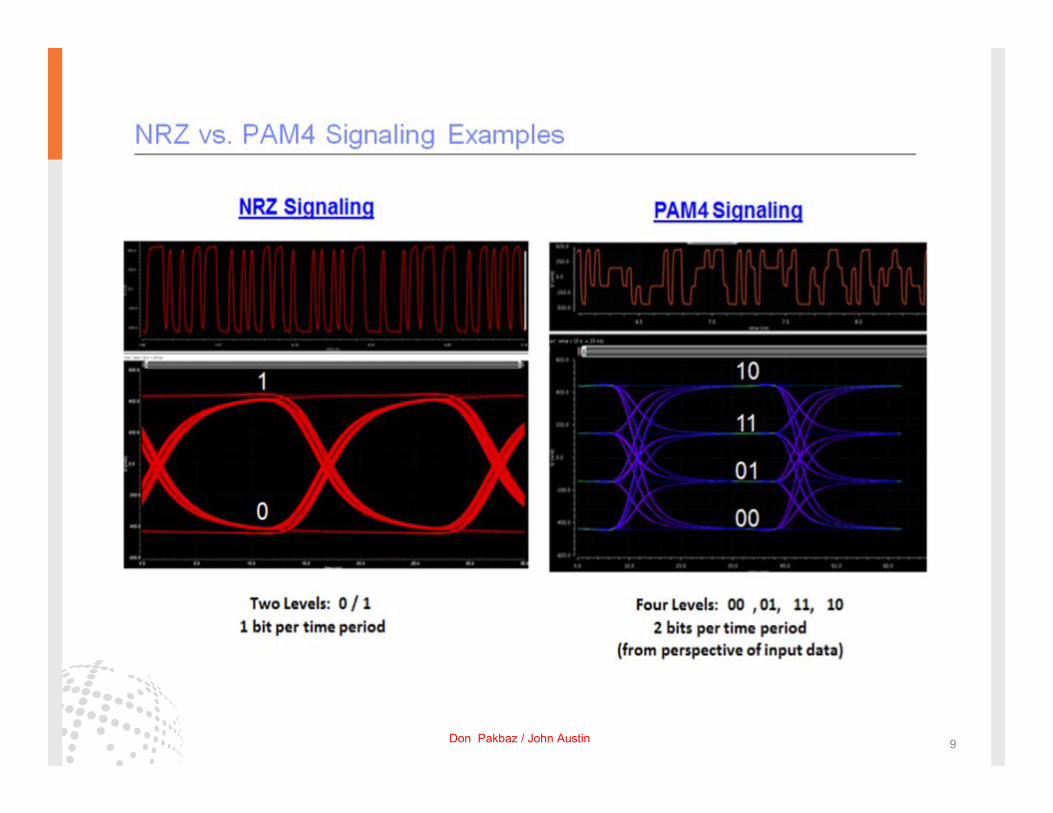
PAM4 Signaling
Adjusted PAM4distance betweentwo constellation points to produceamplitude of signalbetween 300mV to-300mV
10
11
01
00
00 01 11 10
Don Pakbaz / John Austin 10
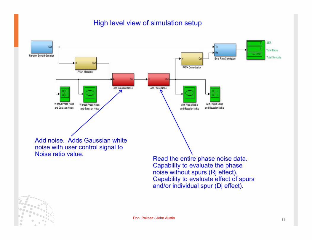
Add noise. Adds Gaussian white noise with user control signal toNoise ratio value.
Read the entire phase noise data.Capability to evaluate the phase noise without spurs (Rj effect).Capability to evaluate effect of spursand/or individual spur (Dj effect).
High level view of simulation setup
Don Pakbaz / John Austin 11
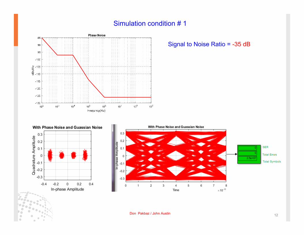
Simulation condition # 1
Signal to Noise Ratio = -35 dB
Don Pakbaz / John Austin 12
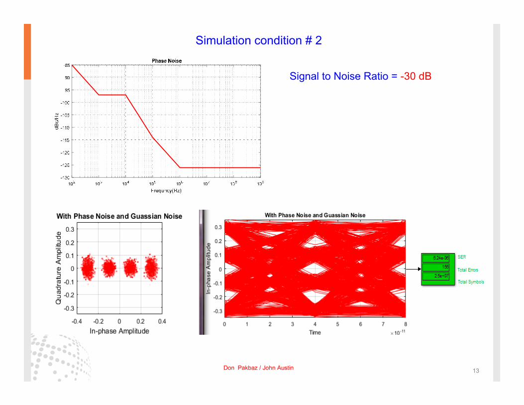
Signal to Noise Ratio = -30 dB
Simulation condition # 2
Don Pakbaz / John Austin 13
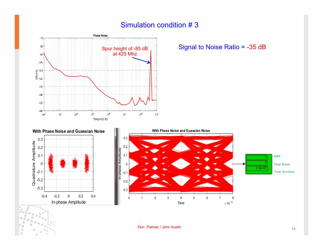
Simulation condition # 3
Signal to Noise Ratio = -35 dBSpur height of -85 dBat 425 Mhz
Don Pakbaz / John Austin 14
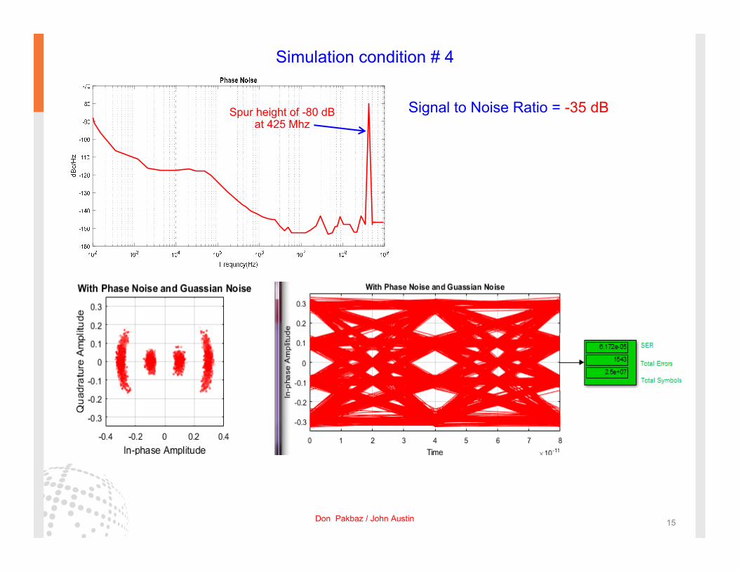
Spur height of -80 dBat 425 Mhz
Simulation condition # 4
Signal to Noise Ratio = -35 dB
Don Pakbaz / John Austin 15

Signal to Noise Ratio = -35 dBMany spurs but their widthis relatively narrow
Don Pakbaz / John Austin 16

Summary The behavioral modeling of HSS PLL and CDR was demonstrated using Bode plots
information and utilizing Matlab/Simulink Tool Boxes.
Deterministic Jitter(Dj) was calculated based on the effect of HSS PLL closed loop Bandwidth,PLL loop multiplier and CDR using MJSQ guidelines.
Tx and Rx are modeled as ideal without the effect of S-parameters and channel lostto isolate just the effect of carrier Phase Noise and “signal to noise” ratio of the system.
The effect of phase noise in various scenarios were simulated. This includesevaluating phase noise without the spurs, with all the measured spurs and individual spur.
The capability of detecting SER/Total Error based on the number of user defined symbol was demonstrated.
Don Pakbaz / John Austin 17
*MJSQ: Methodologies for Jitter and Signal Quality Specification.*CDR: Clock Data Recovery.*HSS: High Speed Serial Link*Tx: Transmitter.*RX: Receiver.*SER: Symbol Error Rate.*PAM4: Pulse Amplitude Modulation.*VCO: Voltage Controlled Oscillator.*Rj: Random Jitter.*Dj: Deterministic Jitter.*PLL: Phase Locked Loop.