ehb xp14 0706 - innovation-group.com.uainnovation-group.com.ua/downloads/eh/60/hp/xp14.pdfxp14 elite...
TRANSCRIPT

E N G I N E E R I N G D A T A
XP14ELITE® SERIES
R−410A
H E A T P U M P O U T D O O R U N I T S
Bulletin No. 210495
June 2007
SEER up to 16.01.5 to 5 Tons
Cooling Capacity − 19,100 to 59,000 BtuhHeating Capacity − 16,700 to 56,000 Btuh
MODEL NUMBER IDENTIFICATION
P 14 036− −
Unit TypeP = Heat Pump Outdoor Unit
Series
Nominal Cooling Capacity018 = 1.5 tons024 = 2 tons030 = 2.5 tons036 = 3 tons042 = 3.5 tons048 = 4 tons060 = 5 tons
Minor Revision Number
230
Voltage230 = 208/230V−1ph−60hz
Refrigerant TypeX = R−410A
X 2−

XP14 − 1.5 to 5 Ton Heat Pump / Page 2
FEATURES
CONTENTS
ARI Rating Tables Pages 9−19. . . . . . . . . . . . . . . . . . . . . . .
Dimensions Page 7. . . . . . . . . . . . . . . . . . . . . . . . . . . . . . . . .
Electrical Data Page 5. . . . . . . . . . . . . . . . . . . . . . . . . . . . . .
Features Page 2. . . . . . . . . . . . . . . . . . . . . . . . . . . . . . . . . . .
Field Wiring Page 6. . . . . . . . . . . . . . . . . . . . . . . . . . . . . . . .
Indoor Coil / Air Handler Substitution Page 8. . . . . . . . . . .
Installation Clearances Page 6. . . . . . . . . . . . . . . . . . . . . . .
Model Number Identification Page 1. . . . . . . . . . . . . . . . . .
Optional Accessories Page 5. . . . . . . . . . . . . . . . . . . . . . . .
Outdoor Sound Data Page 6. . . . . . . . . . . . . . . . . . . . . . . . .
Specifications Page 5. . . . . . . . . . . . . . . . . . . . . . . . . . . . . . .
Warranty
Compressor − limited warranty for ten years inresidential installations and five years in non−residentialinstallations.All other covered components − five years inresidential installations and one year in non−residentialinstallations.Refer to Lennox Equipment Limited Warranty certificateincluded with unit for specific details.
Approvals
Certified in Accordance with the USE certificationprogram, which is based on ARI Standard 210/240.Sound rated in Lennox reverberant sound test room inAccordance with test conditions included in ARI Standard270.Tested in the Lennox Research Laboratory environmentaltest room.Rated According to U.S. Department of Energy (DOE)test procedures.Units and components within bonded for grounding tomeet safety standards for servicing required by UL, NECand CEC.Units are UL and ULC listed.ISO 9001 Registered Manufacturing Quality System.ENERGY STAR® certified units are designed to use lessenergy, help save money on utility bills, and help protectthe environment.
Applications
SEER up to 16.0.Heating COP up to 4.08.HSPF (Region IV) up to 9.50.1.5 through 5 tons.Single phase power supply.Vertical air discharge allows concealment behind shrubsat grade level or out of sight on a roof.Designed for applications with remotely located indoor airhandler units or gas furnaces with indoor add−on coils.When heat pumps are used with gas furnaces, a dual−fuelcontrol (i.e. FM21) or a control system with dual−fuelcapabilities (i.e. Harmony III�, LZP−2 or LZP−4) must beused (ordered extra).See Indoor Coils and Air Handlers sections for indoor unitdata.Units shipped completely factory assembled, piped andwired. Each unit is test operated at the factory insuringproper operation.Installer must set outdoor unit, connect refrigerant linesand make electrical connections to complete job.
For expanded ratings, see www.lennoxdavenet.com.
B
D
E
C
G
F
HI
L
K
M
J
REFRIGERATION SYSTEM
RefrigerantNon−chlorine, ozone friendly, R−410A.Unit pre−charged with refrigerant.See Specification table.
Outdoor Coil FanDirect drive fan moves large air volumes uniformlythrough entire outdoor coil for high refrigerant coolingcapacity.Vertical air discharge minimizes operating sounds andeliminates damage to lawn and shrubs.Fan motor has sleeve bearings and is inherentlyprotected.Motor totally enclosed for maximum protection fromweather, dust and corrosionFan guard constructed of corrosion−resistant PVC(polyvinyl chloride) coated steel.Fan service access accomplished by removal of fanguard.
Copper Tube/Enhanced Fin CoilLennox designed and fabricated coil.Ripple-edged aluminum fins.Copper tube construction.Lanced fins provide maximum exposure of fin surface toair stream resulting in excellent heat transfer.Fin collars grip tubing for maximum contact area.Flared shoulder tubing connections/silver solderingconstruction.Coil is factory tested under high pressure to ensureleakproof construction.Entire coil is accessible for cleaning.
High Pressure SwitchProtects the system from high pressure conditions thatcan be a result of fan failure or a blocked/dirty coil.Automatic reset.
B
C
D

XP14 − 1.5 to 5 Ton Heat Pump / Page 3
FEATURES
REFRIGERANT SYSTEM − CONTINUED
Low Pressure SwitchShuts off unit if suction pressure falls below setting.Provides loss of charge and freeze-up protection.Automatic reset.
Expansion Valve − Outdoor UnitDesigned and sized specifically for use in heat pump system.Sensing bulb is located on the suction line between thecoil and the reversing valve thus sensing evaporator outtemperature in any cycle.Factory installed and piped.
Reversing Valve4-way interchange reversing valve effects a rapid changein direction of refrigerant flow resulting in quickchangeover from cooling to heating and vice versa.Valve operates on pressure differential between outdoorunit and indoor unit of the system. Factory installed.
Hi-Capacity Liquid Line DrierFactory installed in the liquid line, the drier traps moistureor dirt that could contaminate the refrigerant system.100% molecular−sieve bead type drier.
OPTIONS
Check/Expansion Valve KitsMust be ordered extra and field installed on certain indoorunits.See ARI Ratings tables.Chatleff style fitting.
FreezestatInstalls on or near the vapor line of the indoor coil or on thesuction line.Senses suction line temperature and cycles thecompressor off when suction line temperature falls belowit’s setpoint.Opens at 29°F and closes at 58°F.
Refrigerant Line KitsRefrigerant lines (suction & liquid) are shipped refrigerationclean. Lines are cleaned, dried, pressurized and sealed atfactory.Suction line fully insulated.Lines are stubbed at both ends.Not available for −060 models and must be field fabricated.
Compressor
Scroll CompressorCompressor features highefficiency with uniform suctionflow, constant discharge flowand high volumetric efficiencyand quiet operation.Compressor consists of twoinvolute spiral scrolls matchedtogether to generate a series ofcrescent shaped gas pocketsbetween them.During compression, one scrollremains stationary while theother scroll orbits around it.Gas is drawn into the outerpocket, the pocket is sealed asthe scroll rotates.As the spiral movement continues, gas pockets arepushed to the center of the scrolls. Volume between thepockets is simultaneously reduced.When pocket reaches the center, gas is now at highpressure and is forced out of a port located in the center ofthe fixed scrolls.During compression, several pockets are compressedsimultaneously resulting in a smooth continuouscompression cycle.Continuous flank contact, maintained by centrifugal force,minimizes gas leakage and maximizes efficiency.Scroll compressor is tolerant to the effects of slugging andcontaminants. If this occurs, scrolls separate, allowingliquid or contaminants to to be worked toward the centerand discharged.Low gas pulses during compression reduces operationalsound levels.Compressor motor is internally protected from expensivecurrent and temperature.Compressor is installed in the unit on resilient rubbermounts for vibration free operation.
Crankcase Heater (−036−042−048−060)Factory installed on −036, −042, −048 and −060 models.Crankcase heater prevents migration of liquid refrigerantinto compressor and ensures proper compressorlubrication.
Compressor Sound Dampening SystemA polyethylene compressor cover containing a 2 inch thickbatt of fiberglass insulation for better sound dampening.All open edges are sealed with a one−inch wide hook andloop fastening tape.
OPTIONS
Crankcase Heater (Optional for −018−024−030)Crankcase heater prevents migration of liquid refrigerantinto compressor and ensures proper compressorlubrication.
Compressor Hard Start KitSingle−phase units are equipped with a PSC compressormotor.This type of motor normally does not need a potentialrelay and start capacitor.In conditions such as low voltage, kit may be required toincrease the compressor starting torque.
Compressor Low Ambient Cut−OffNon-adjustable switch (low ambient cut-out) preventscompressor operation when outdoor temperature isbelow 35°F.
E
F
G
H
I

XP14 − 1.5 to 5 Ton Heat Pump / Page 4
FEATURES
CONTROLS
Defrost ControlSolid-state control furnished as standard.Gives a demand defrost cycle whenever system heatingperformance falls below optimum levels. The sensingelement on coil determines when defrost cycle is requiredand when to terminate cycle.Anti−short cycle (5 minutes) incorporated into the board.Diagnostic LED’s furnished as an aid in troubleshooting.Conveniently located in control box.
OPTIONS
Indoor Blower Off Delay RelayDelays the indoor blower−off time during the cooling cycle.See ARI Rating Tables for usage.
Low Ambient KitHeat pump in the cooling mode will operate satisfactorilydown to 45�F outdoor air temperature without anyadditional controls.Kit can be added in the field enabling unit to operateproperly down to 30�F.Crankcase heater (optional for −018−024−030 models) andfreezestat should be installed on compressors equippedwith a low ambient kit.A compressor lock−out thermostat should be added toterminate compressor operation below recommendedoperation conditions.
Low Pressure Switch Bypass ThermostatFor use in applications where the heat pump is operated inoutdoor ambient temperatures below 15°F.Prevents nuisance trips from the low pressure switch.Wired in parallel with the low pressure switch.
Mild Weather KitHeat pump units operate satisfactorily in the heatingmode at outdoor air temperatures up to 75�F.Mild Weather Kit can be field installed, allowing heatingoperation above 75�F.
Monitor Kit − Service LightContains ambient compensating thermistor and servicelight thermostat.For use with thermostats requiring input for indicator lights.
Outdoor Thermostat KitAn outdoor thermostat can be used to lock out some of theelectric heating elements on indoor units where two stagecontrol is applicable.Outdoor thermostat maintains the heating load on the lowpower input as long as possible before allowing the fullpower load to come on the line.Thermostat kit and mounting box must be ordered extra.
Cabinet
Heavy−gauge steel constructionPre−painted cabinet finish.Painted base section.Control box is conveniently located with all controlsfactory wired.Corner patch plate allows access to compressorcomponents.Drainage holes are provided in base section for moistureremoval.Drainage holes are provided in base section for moistureremoval.High density polyethylene unit support feet raise the unit offof the mounting surface, away from damaging moisture.
SmartHinge� Louvered Coil ProtectionSteel louvered panelsprovides complete coilprotection.Panels are hinged toallow easy cleaningand servicing of coils.Panels may becompletely removed.Interlocking tabs andslots assure tight fit oncabinet.
Refrigerant Line Connections, Electrical Inlets andService ValvesSuction and liquid lines are located on corner of unitcabinet and are made with sweat connections. Seedimension drawing.Fully serviceable brass service valves prevent corrosionand provide access to refrigerant system. Suction valvecan be fully shut off, while liquid valve may be front seatedto manage refrigerant charge while servicing system.Suction and liquid line service valves and gauge ports arelocated inside the cabinet.Refrigerant line connections and field wiring inlets arelocated in one central area of the cabinet. See dimensiondrawing.
JK
L
M

XP14 − 1.5 to 5 Ton Heat Pump / Page 5
SPECIFICATIONS
GeneralD t
Model No. XP14−018 XP14−024 XP14−030 XP14−036 XP14−042 XP14−048 XP14−060Data Nominal Tonnage 1.5 2 2.5 3 3.5 4 5
Connections( t)
Liquid line o.d. − in. 3/8 3/8 3/8 3/8 3/8 3/8 3/8(sweat) Vapor line o.d. − in. 3/4 3/4 3/4 7/8 7/8 7/8 1-1/81 Refrigerant R−410A charge furnished 8 lbs.
4 oz.8 lbs.0 oz.
7 lbs.2 oz.
9 lbs.12 oz.
12 lbs.7 oz.
12 lbs.10 oz.
16 lbs.0 oz.
OutdoorC il
Net face areaft
Outer coil 13.30 13.30 15.21 19.39 24.93 24.93 29.09Coil sq. ft. Inner coil 12.60 12.60 14.50 18.77 24.13 24.13 28.16
Tube diameter − in. 5/16 5/16 5/16 5/16 5/16 5/16 5/16
No. of rows 2 2 2 2 2 2 2
Fins per inch 22 22 22 22 22 22 22
OutdoorF
Diameter − in. 18 18 18 26 26 26 26Fan No. of Blades 3 3 3 4 4 4 4
Motor hp 1/10 1/10 1/10 1/3 1/3 1/3 1/3
Cfm 2165 2165 2232 4090 4347 4347 4550
Rpm 1015 1015 1035 844 843 843 830
Watts 171 171 165 299 299 299 307
Shipping Data − lbs. 1 package 194 194 205 263 317 319 345
ELECTRICAL DATA
Line voltage data − 60 hz − 1ph 208/230V 208/230V 208/230V 208/230V 208/230V 208/230V 208/230V2 Maximum overcurrent protection (amps) 20 30 30 30 40 50 60
3 Minimum circuit ampacity 11.9 17.5 17.0 19.4 24.2 29 34.8
Compressor Rated Load Amps 8.97 13.46 13.1 14.1 17.94 21.79 26.41p
Locked Rotor Amps 48 58 64 77 112 117 134
Power Factor 0.96 0.98 0.98 0.99 0.94 0.95 0.98
OutdoorF M t
Full Load Amps 0.70 0.70 0.70 1.8 1.8 1.8 1.8Fan Motor Locked Rotor Amps 1.4 1.4 1.4 2.9 2.9 2.9 2.9
OPTIONAL ACCESSORIES − must be ordered extra
Compressor Crankcase Heater 93M04 � � �p
Factory � � � �
Compressor Hard Start Kit 10J42 � � � � � �p
81J69 �
Compressor Low Ambient Cut−Off 45F08 � � � � � � �
Freezestat 3/8 in. tubing 93G35 � � � � � � �
5/8 in. tubing 50A93 � � � � � � �
Indoor Blower Off Delay Relay 58M81 � � � � � � �
4 Low Ambient Kit 54M89 � � � � � � �
Low Pressure Switch Bypass Thermostat 13W07 � � � � � � �
Mild Weather Kit 33M07 � � � � � � �
Monitor Kit − Service Light 76F53 � � � � � � �
OutdoorTh t t Kit
Thermostat 56A87 � � � � � � �
Thermostat Kit Mounting Box 31461 � � � � � � �
RefrigerantLine Sets
L15−41−20L15−41−30
L15−41−40L15−41−50
� � �
e Sets
L15−65−30 L15−65−40L15−65−50
� � �
Field Fabricate �
NOTE − Extremes of operating range are plus 10% and minus 5% of line voltage.1 Refrigerant charge sufficient for 15 ft. length of refrigerant lines.2 HACR type circuit breaker or fuse.3 Refer to National or Canadian Electrical Code manual to determine wire, fuse and disconnect size requirements.4 Crankcase Heater and Freezestat are recommended with Low Ambient Kit.

XP14 − 1.5 to 5 Ton Heat Pump / Page 6
INSTALLATION CLEARANCES − INCHES (MM)
ÍÍÍÍÍÍÍÍÍÍÍÍÍÍÍÍÍÍÍÍÍÍÍÍÍÍÍÍÍÍÍÍÍÍÍÍÍÍÍÍÍÍÍÍÍÍÍÍÍÍÍÍÍÍÍÍÍÍÍÍÍÍÍÍÍÍÍÍÍÍÍÍÍÍÍÍÍÍÍÍÍÍÍÍÍÍÍÍÍÍÍÍÍÍÍÍÍÍÍÍÍÍÍÍÍÍÍÍÍÍÍÍÍÍÍÍÍÍÍÍÍÍÍÍÍÍÍÍÍÍÍÍÍÍÍÍÍÍÍÍÍÍÍÍÍÍÍÍÍÍÍÍÍÍÍÍÍÍÍÍÍÍÍÍÍÍÍÍ
SeeNOTES
See NOTESNOTES:
Service clearance of 30 in. (762 mm) must be maintained on oneof the sides adjacent to the control box.
Clearance to one of the other three sides must be 36 in. (914 mm).
Clearance to one of the remaining two sides may be 12 in. (305mm) and the final side may be 6 in. (152 mm).
A clearance of 24 in. (610 mm) must be maintained between twounits.
48 in. (1219 mm) clearance required on top of unit.
SeeNOTES
See NOTESControl
Box
FIELD WIRING
DISCONNECTSWITCH
(By Others)
OPTIONALOUTDOOR
THERMOSTAT
A � Two Wire Power (see Electrical Data)
B � Two or Three Wire Power (size to heater capacity)
C � Twelve Wire Low Voltage � 18 ga. minimum
� Fourteen Wire Low Voltage with Optional Outdoor Thermostat
D � Eight Wire Low Voltage � 18 ga. minimum
� Ten Wire Low Voltage with Optional Outdoor Thermostat
� Field Wiring Not Furnished �
All wiring must conform to NEC or CEC and local electrical codes.
LENNOXINDOOR UNIT
OPTIONALELECTRIC
HEAT
THERMOSTAT(Optional)
LENNOXOUTDOOR
UNIT
DISCONNECTSWITCH
(By Others)
A
B
CD
OUTDOOR SOUND DATA
1 UnitModel No
Octave Band Sound Power Levels dBA, re 10−12 WattsCenter Frequency − HZ
1 SoundRatingModel No.
125 250 500 1000 2000 4000 8000
RatingNumber (dB)
XP14−018 70.5 67.5 69.5 66.5 59.5 53.5 47.5 71
XP14−024 71 68 68.5 65.5 60 54.5 48.5 71
XP14−030 71.5 66.5 67.5 65.5 59.5 54.5 48.5 71
XP14−036 80.5 70.5 69.5 65.5 60.5 55 51 71
XP14−042 82 70.5 70 67 63.5 55.5 52.5 71
XP14−048 80.5 70.5 70 66.5 61.5 55.5 53.5 73
XP14−060 82 69.5 69 67.5 63.5 66 53.5 73
NOTE − the octave sound power data does not include tonal correction.1 Tested according to ARI Standard 270 test conditions.

XP14 − 1.5 to 5 Ton Heat Pump / Page 7
DIMENSIONS − INCHES (MM)
ELECTRICALINLETS
SIDE VIEW
DISCHARGE AIR
VAPOR LINECONNECTION
LIQUID LINECONNECTION
A
BC
4−1/4(108)4−3/4
(121)
1 (25)
2 (51)
END VIEW
TOP VIEW
VAPOR LINECONNECTION
LIQUID LINECONNECTION
UNIT SUPPORTFEET
8−1/2(216)
XP14−018−030 BASE SECTION
8−3/4(222)
5−1/2(140)
9−1/2(241)
8−1/4(210)
13−1/2(343)
UNIT SUPPORTFEET
XP14−036 TO −60 BASE SECTION
16−7/8(429)
4−5/8(117)
26−7/8(683)
8−3/4(222)
30−3/4(781)
3−3/4(95)
3−1/8(79)
Model NoA B C
Model No.in. mm in. mm in. mm
XP14−018 31 787 27 686 28 711
XP14−024 31 787 27 686 28 711
XP14−030 35 889 27 686 28 711
XP14−036 31 787 35−1/2 902 39−1/2 1003
XP14−042 39 991 35−1/2 902 39−1/2 1003
XP14−048 39 991 35−1/2 902 39−1/2 1003
XP14−060 45 1143 35−1/2 902 39−1/2 1003

XP14 − 1.5 to 5 Ton Heat Pump / Page 8
ARI RATINGS − INDOOR COIL / AIR HANDLER SUBSTITUTION
Substituting Coils in the ARI TablesMost R−22 and R−410A indoor coils and air handlers arethe same except for the factory installed expansiondevice. C33 coils can be used in place of the CX34 coils,CB26UH, CB27UH, CB30M and CB31MV air handlerscan be used in place of the CBX26UH, CBX27UH,CBX32M and CBX32MV, respectively.
The expansion device is based on the size of the outdoorunit. The factory installed RFC or TXV on theC33/CB26UH/CB27UH/CB31MV/CB30M must bereplaced to correspond to the outdoor unit. The correctTXV’s are:
1.5−2.5 ton heat pumps 49L243−3.5 ton heat pumps 49L254−5 ton heat pumps 91M02
Example:A four−ton heat pump is being installed. The ARI tableshows that CBX32MV−048 is a matching air handler. ACB31MV−51 with a 91M02 TXV can be used in its place.
UP−FLOW COILS
R−410A R−22
CX34−18/24A−6F = C33−24A−2
CX34−18/24B−6F = C33−24B−2
CX34−18/24C−6F = C33−24C−2
CX34−19A−6F = C33−19A−2
CX34−25A−6F = C33−25A−2
CX34−25B−6F = C33−25B−2
CX34−30A−6F = C33−30A−2
CX34−30B−6F = C33−30B−2
CX34−30C−6F = C33−30C−2
CX34−31A−6F = C33−31A−2
CX34−31B−6F = C33−31B−2
CX34−36A−6F = C33−36A−2
CX34−36B−6F = C33−36B−2
CX34−36C−6F = C33−36C−2
CX34−38A−6F = C33−38A−2
CX34−38B−6F = C33−38B−2
CX34−42B−6F = C33−42B−2
CX34−43B−6F = C33−43B−2
CX34−43C−6F = C33−43C−2
no equivalent C33−44C−2
CX34−44/48B−6F = C33−48B−2
CX34−44/48C−6F = C33−48C−2
CX34−49C−6F = C33−49C−2
CX34−50/60C−6F = C33−50/60C−2
CX34−60D−6F = C33−60D−2
CX34−62C−6F = C33−62C−2
CX34−62D−6F = C33−62D−2
AIR HANDLERS
R−410A R−22
CBX26UH−018 = CB26UH−018−R
CBX26UH−024 = CB26UH−024−R
CBX26UH−030 = CB26UH−030−R
CBX26UH−036 = CB26UH−036−R
CBX26UH−042 = CB26UH−042−R
CBX26UH−048 = CB26UH−048
CBX26UH−060 = CB26UH−060−R
CBX27UH−018/024 = CB27UH−018/024
CBX27UH−030 = CB27UH−030
CBX27UH−036 = CB27UH−036
CBX27UH−042 = CB27UH−042
CBX27UH−048 = CB27UH−048
CBX27UH−060 = CB27UH−060
CBX32M−018/024 = CB30M−21/26
CBX32M−030 = CB30M−31
CBX32M−036 = CB30M−41
CBX32M−042 = CB30M−46
CBX32M−048 = CB30M−51
CBX32M−060 = CB30M−65
CBX32MV−018/024 no equivalent
CBX32MV−024/030 no equivalent
CBX32MV−036 = CB31MV−41
CBX32MV−048 = CB31MV−51
CBX32MV−060 = CB31MV−65
CBX32MV−068 no equivalent

XP14 − 1.5 to 5 Ton Heat Pump / Page 9
ARI RATINGS
1 ARI Standard 210/240 Ratings
Capacity − Btuh Efficiency Total Watts COPI d U it M d l N
Expansion
CoolingHigh
TempLow
TempHSPF
CoolHigh Low High Low
Indoor Unit Model No.ExpansionDevice
Cooling Temp.Heating
Temp.Heating SEER EER IV V
CoolHighHeat
LowHeat
HighHeat
LowHeat
XP14−018 1.5 TON
Air Handlers Air Handlers
19,100 16,800 10,100 14.00 12.00 7.70 6.70 1590 1450 1350 3.40 2.20 4 CBX32MV−018/024 (Multi−Position) Factory TXV
19,400 16,700 10,000 15.00 12.50 8.00 6.70 1550 1375 1280 3.56 2.28 4,5 CBX27UH−018 (Up−Flow / Horizontal) Factory TXV
XP14−024 2 TON
Air Handlers Air Handlers
23,000 23,400 14,900 13.00 11.00 8.00 6.70 2090 1935 1825 3.54 2.40 3 CBX32M−018/024 (Multi−Position) Factory TXV
23,400 23,200 14,800 14.00 11.50 8.25 7.20 2035 1855 1755 3.66 2.46 4 CBX32MV−018/024 (Multi−Position) Factory TXV
23,600 23,200 14,700 14.00 12.00 8.25 7.20 1965 1865 1740 3.64 2.48 5 CBX26UH−024 (Up−Flow / Horizontal) Factory TXV
23,600 23,200 14,700 14.00 12.00 8.50 7.20 1965 1810 1730 3.76 2.48 3 CBX32M−030 (Multi−Position) Factory TXV
23,600 23,200 14,700 14.00 12.00 8.50 7.20 1965 1800 1720 3.78 2.50 4 CBX32MV−024/030 (Multi−Position) Factory TXV
24,200 23,000 14,400 15.00 13.00 9.00 7.50 1860 1690 1620 3.98 2.60 4 CBX27UH−024 (Up−Flow / Horizontal) Factory TXV
Up−Flow Indoor Coils Up−Flow Coils
23,200 23,200 14,800 13.00 11.00 7.70 6.70 2110 1975 1870 3.44 2.32 3 CX34−36A/B/C−6F Factory TXV
23,400 23,200 14,700 13.00 11.00 7.70 6.70 2125 1990 1940 3.42 2.22 3 CX34−25A−6F Factory TXV
23,600 23,400 15,000 13.00 11.00 7.70 6.70 2145 1920 1795 3.58 2.44 3 CX34−38A−6F Factory TXV
23,800 23,200 14,700 13.00 11.00 7.70 6.70 2165 1995 1930 3.40 2.24 3 CX34−31A−6F Factory TXV
Up−Flow Indoor Coils + Furnaces Up−Flow Coils + Furnaces
23,800 22,600 14,300 15.00 12.50 8.50 7.20 1905 1760 1660 3.76 2.52 CX34−36B−6F 4 G60UHV−36B−090 Factory TXV
23,800 22,600 14,300 15.00 13.00 8.25 7.20 1830 1775 1665 3.74 2.52 CX34−36C−6F 4 G61MPV−36C−090 Factory TXV
23,800 22,800 14,300 15.00 12.50 8.50 7.20 1905 1780 1680 3.76 2.50 CX34−36B−6F 4 G61MPV−36B−070 Factory TXV
23,800 22,800 14,400 15.00 12.50 8.25 7.20 1905 1785 1685 3.74 2.50 CX34−36A−6F 4 G60UHV−36A−070 Factory TXV
23,800 22,800 14,400 15.00 12.50 8.25 7.20 1905 1785 1685 3.74 2.50 CX34−36B−6F 4 G61MPV−36B−045 Factory TXV
24,000 22,600 14,200 15.00 13.00 8.25 7.00 1845 1775 1725 3.74 2.42 CX34−25B−6F 4 G60UHV−36B−090 Factory TXV
24,000 22,600 14,200 15.00 12.50 8.20 7.00 1920 1795 1745 3.70 2.38 CX34−25B−6F 4 G61MPV−36B−070 Factory TXV
24,000 22,800 14,300 15.00 12.50 8.00 7.00 1920 1820 1775 3.68 2.36 CX34−25A−6F 4 G60UHV−36A−070 Factory TXV
24,000 22,800 14,300 15.00 12.50 8.20 7.00 1920 1800 1755 3.72 2.38 CX34−25B−6F 4 G61MPV−36B−045 Factory TXV
24,200 22,800 14,400 15.00 13.00 9.00 7.50 1860 1710 1590 3.90 2.66 CX34−38B−6F 4 G60UHV−36B−090 Factory TXV
24,200 23,000 14,500 15.00 13.00 8.75 7.50 1860 1735 1615 3.88 2.62 CX34−38A−6F 4 G60UHV−36A−070 Factory TXV
24,200 23,000 14,500 15.00 13.00 8.75 7.50 1860 1735 1615 3.88 2.62 CX34−38B−6F 4 G61MPV−36B−045 Factory TXV
24,200 23,000 14,500 15.00 13.00 9.00 7.50 1860 1725 1610 3.90 2.64 CX34−38B−6F 4 G61MPV−36B−070 Factory TXV
24,400 22,600 14,200 15.00 13.00 8.20 7.00 1875 1800 1750 3.68 2.38 CX34−31A−6F 4 G60UHV−36A−070 Factory TXV
24,400 22,600 14,200 15.00 13.00 8.25 7.00 1875 1780 1725 3.72 2.42 CX34−31B−6F 4 G60UHV−36B−090 Factory TXV
24,400 22,600 14,200 15.00 13.00 8.20 7.00 1875 1795 1745 3.70 2.38 CX34−31B−6F 4 G61MPV−36B−070 Factory TXV
24,400 22,800 14,300 15.00 13.00 8.20 7.00 1875 1795 1755 3.72 2.38 CX34−31B−6F 4 G61MPV−36B−045 Factory TXV
NOTE − When used with gas furnaces, a dual−fuel control (i.e. FM21) or a control system with dual−fuel capabilities (i.e. Harmony III, LZP−2 or LZP−4) must be used (ordered extra).1 Certified in accordance with USE certification program which is based on ARI Standard 210/240 with 25 ft. of connecting refrigerant lines;
Cooling Ratings − 95�F outdoor air temperature and 80�F db/67�F wb entering indoor coil air.High Temperature Heating Ratings − 47�F db/43�F wb outdoor air temperature and 70�F db entering indoor coil air.Low Temperature Heating Ratings − 17�F db/15�F wb outdoor air temperature and 70�F db entering indoor coil air.
2 Factory installed expansion valve or RFC on indoor unit MUST be replaced with valve specified (if equipped).3 Blower must be capable of time−off blower delay. Indoor Blower Off Delay Relay (58M81) is recommend for field installation.4 Blower control must be set for a time−off blower delay.5 Most popular air handler combination.

XP14 − 1.5 to 5 Ton Heat Pump / Page 10
ARI RATINGS
1 ARI Standard 210/240 Ratings
Capacity − Btuh Efficiency Total Watts COPI d U it M d l N
Expansion
CoolingHigh
TempLow
TempHSPF
CoolHigh Low High Low
Indoor Unit Model No.ExpansionDevice
Cooling Temp.Heating
Temp.Heating SEER EER IV V
CoolHighHeat
LowHeat
HighHeat
LowHeat
XP14−024 2 TON
Down−Flow Indoor Coils Down−Flow Coils
23,600 23,400 15,000 13.00 11.00 7.70 6.70 2145 1900 1770 3.60 2.48 3 CR33−30/36A/B/C−F 2 49L24
Down−Flow Indoor Coils + Furnaces Down−Flow Coils + Furnaces
24,200 23,200 14,700 15.00 12.50 9.00 7.70 1935 1730 1615 3.94 2.66 CR33−30/36A−F 4 G60DFV−36A−070 2 49L24
24,200 22,800 14400 15.00 13.00 9.00 7.70 1860 1700 1570 3.94 2.68 CR33−30/36C−F 4 G61MPV−36C−090 2 49L24
24,200 23,000 14500 15.00 13.00 9.00 7.70 1860 1705 1585 3.96 2.68 CR33−30/36B−F 4 G61MPV−36B−070 2 49L24
24,200 23,000 14600 15.00 13.00 9.00 7.70 1860 1715 1595 3.94 2.68 CR33−30/36B−F 4 G61MPV−36B−045 2 49L24
24,600 23,200 14600 15.00 13.00 9.00 7.70 1890 1670 1565 4.08 2.74 CR33−30/36B−F 4 G60DFV−36B−090 2 49L24
Horizontal Indoor Coils Horizontal Coils
23,200 23,200 14,700 13.00 11.00 7.70 6.70 2110 2010 1940 3.38 2.22 3 CH33−36A−2F 2 49L24
23,400 23,200 14,700 13.00 11.00 7.70 6.70 2125 1985 1940 3.42 2.22 3 CH33−25A−2F 2 49L24
23,400 23,200 14,900 13.00 11.00 7.70 6.70 2125 1970 1840 3.46 2.38 3 CH23−41 2 49L24
23,400 23,400 14,900 13.00 11.00 7.70 6.70 2125 1930 1850 3.56 2.36 3 CH33−36C−2F 2 49L24
23,600 23,200 14,700 13.00 11.00 7.70 6.70 2145 1990 1935 3.42 2.22 3 CH33−42B−2F 2 49L24
23,800 23,200 14,700 13.00 11.00 7.70 6.70 2165 1960 1945 3.46 2.22 3 CH33−31A/B−2F 2 49L24
Horizontal Indoor Coils + Furnaces Horizontal Coils + Furnaces
23,800 22,800 14,300 14.50 12.50 8.00 6.70 1905 1830 1775 3.66 2.36 CH33−36A−2F 4 G60UHV−36A−070 2 49L24
24,000 22,400 14,200 15.00 13.00 9.00 7.70 1845 1715 1590 3.82 2.62 CH23−41 4 G61MPV−36C−090 2 49L24
24,000 22,600 14,200 15.00 13.00 8.75 7.50 1845 1720 1600 3.86 2.60 CH23−41 4 G60UHV−36A−070 2 49L24
24,000 22,600 14,200 15.00 13.00 8.75 7.50 1845 1720 1600 3.86 2.60 CH23−41 4 G61MPV−36B−070 2 49L24
24,000 22,600 14,200 15.00 13.00 8.75 7.50 1845 1720 1600 3.86 2.60 CH23−41 4 G61MPV−36B−071 2 49L24
24,000 22,800 14,300 15.00 12.50 8.00 6.70 1920 1810 1775 3.70 2.36 CH33−25A−2F 4 G60UHV−36A−070 2 49L24
24,000 22,800 14,300 15.00 13.00 8.50 7.00 1845 1730 1655 3.86 2.54 CH33−36C−2F 4 G61MPV−36C−090 2 49L24
24,200 22,400 14,100 15.00 13.00 9.00 7.70 1860 1690 1570 3.88 2.62 CH23−41 4 G60UHV−36B−090 2 49L24
24,200 22,600 14,300 15.00 13.00 8.75 7.50 1860 1725 1605 3.84 2.60 CH23−41 4 G61MPV−36B−045 2 49L24
24,400 22,400 14,000 16.00 13.50 8.50 7.00 1805 1710 1660 3.84 2.46 CH33−42B−2F 4 G60UHV−36B−090 2 49L24
24,400 22,600 14,100 16.00 13.00 8.25 7.00 1875 1740 1695 3.80 2.44 CH33−42B−2F 4 G61MPV−36B−045 2 49L24
24,400 22,600 14,100 16.00 13.00 8.25 7.00 1875 1740 1690 3.80 2.44 CH33−42B−2F 4 G61MPV−36B−070 2 49L24
24,400 22,600 14,100 16.00 13.00 8.25 7.00 1875 1740 1690 3.80 2.44 CH33−42B−2F 4 G61MPV−36B−071 2 49L24
24,400 22,600 14,200 15.00 13.00 8.25 7.00 1875 1760 1730 3.76 2.40 CH33−31B−2F 4 G60UHV−36B−090 2 49L24
24,400 22,800 14,200 15.00 13.00 8.00 7.00 1875 1780 1745 3.76 2.38 CH33−31B−2F 4 G61MPV−36B−070 2 49L24
24,400 22,800 14,200 15.00 13.00 8.00 7.00 1875 1780 1745 3.76 2.38 CH33−31B−2F 4 G61MPV−36B−071 2 49L24
24,400 22,800 14,300 15.00 12.50 8.00 6.70 1950 1790 1780 3.74 2.36 CH33−31A−2F 4 G60UHV−36A−070 2 49L24
24,400 22,800 14,300 15.00 13.00 8.00 7.00 1875 1785 1755 3.74 2.38 CH33−31B−2F 4 G61MPV−36B−045 2 49L24
NOTE − When used with gas furnaces, a dual−fuel control (i.e. FM21) or a control system with dual−fuel capabilities (i.e. Harmony III, LZP−2 or LZP−4) must be used (ordered extra).1 Certified in accordance with USE certification program which is based on ARI Standard 210/240 with 25 ft. of connecting refrigerant lines;
Cooling Ratings − 95�F outdoor air temperature and 80�F db/67�F wb entering indoor coil air.High Temperature Heating Ratings − 47�F db/43�F wb outdoor air temperature and 70�F db entering indoor coil air.Low Temperature Heating Ratings − 17�F db/15�F wb outdoor air temperature and 70�F db entering indoor coil air.
2 Factory installed expansion valve or RFC on indoor unit MUST be replaced with valve specified (if equipped).3 Blower must be capable of time−off blower delay. Indoor Blower Off Delay Relay (58M81) is recommend for field installation.4 Blower control must be set for a time−off blower delay.5 Most popular air handler combination.

XP14 − 1.5 to 5 Ton Heat Pump / Page 11
ARI RATINGS
1 ARI Standard 210/240 Ratings
Capacity − Btuh Efficiency Total Watts COPI d U it M d l N
Expansion
CoolingHigh
TempLow
TempHSPF
CoolHigh Low High Low
Indoor Unit Model No.ExpansionDevice
Cooling Temp.Heating
Temp.Heating SEER EER IV V
CoolHighHeat
LowHeat
HighHeat
LowHeat
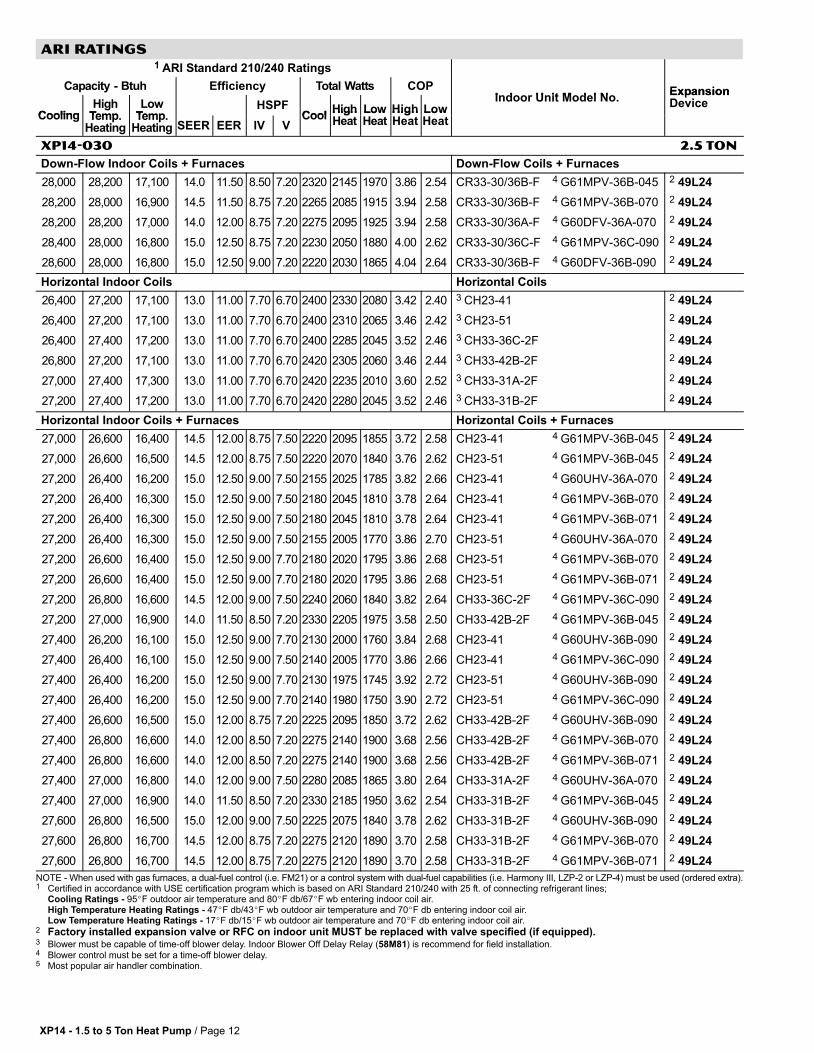
XP14−030 2.5 TON
Air Handlers Air Handlers
27,600 28,000 17,000 13.0 11.50 8.25 7.00 2350 2250 2070 3.64 2.40 3 CBX32M−030 (Multi−Position) Factory TXV
28,000 28,200 17,000 14.0 12.00 8.25 7.00 2330 2200 2035 3.76 2.44 4 CBX32MV−024/030 (Multi−Position) Factory TXV
28,200 28,200 17,100 14.0 12.00 8.25 7.00 2340 2185 2010 3.78 2.50 5 CBX26UH−030 (Up−Flow / Horizontal) Factory TXV
28,400 28,000 16,800 14.5 12.00 8.25 7.00 2280 2135 1990 3.84 2.48 4 CBX32MV−036 (Multi−Position) Factory TXV
28,400 28,200 17,100 14.0 12.00 8.25 7.00 2345 2180 2045 3.80 2.44 3 CBX32M−036 (Multi−Position) Factory TXV
28,600 27,800 16,600 15.0 12.50 8.50 7.00 2225 2080 1930 3.92 2.52 4 CBX27UH−030 (Up−Flow / Horizontal) Factory TXV
Up−Flow Indoor Coils Up−Flow Coils
26,800 27,000 17,100 13.0 11.00 7.70 6.70 2420 2355 2080 3.36 2.40 3 CX34−44/48C−6F Factory TXV
26,800 27,400 17,200 13.0 11.00 7.70 6.70 2420 2255 2035 3.56 2.48 3 CX34−38A/B−6F Factory TXV
27,000 27,200 17,100 13.0 11.00 7.70 6.70 2420 2305 2060 3.46 2.44 3 CX34−31B−6F Factory TXV
27,200 27,200 17,200 13.0 11.00 7.70 6.70 2420 2295 2050 3.48 2.46 3 CX34−43B/C−6F Factory TXV
Up−Flow Indoor Coils + Furnaces Up−Flow Coils + Furnaces
27,200 27,000 16,800 14.0 11.50 8.25 7.20 2330 2210 1965 3.58 2.50 CX34−31B−6F 4 G61MPV−36B−045 Factory TXV
27,200 27,200 17,100 14.0 11.50 8.50 7.20 2330 2160 1945 3.70 2.58 CX34−38B−6F 4 G61MPV−36B−045 Factory TXV
27,400 26,800 16,600 14.0 11.50 8.50 7.20 2260 2135 1890 3.68 2.58 CX34−31A−6F 4 G60UHV−36A−070 Factory TXV
27,400 26,800 16,600 14.0 11.50 8.50 7.20 2275 2150 1905 3.66 2.56 CX34−31B−6F 4 G61MPV−36B−070 Factory TXV
27,400 26,800 16,600 14.0 11.50 8.50 7.20 2275 2150 1905 3.66 2.56 CX34−31B−6F 4 G61MPV−36B−071 Factory TXV
27,400 26,800 16,600 14.5 12.00 9.00 7.50 2225 2050 1825 3.84 2.66 CX34−38B−6F 4 G60UHV−36B−090 Factory TXV
27,400 27,000 16,700 14.0 11.50 8.75 7.20 2260 2085 1865 3.80 2.62 CX34−38A−6F 4 G60UHV−36A−070 Factory TXV
27,400 27,000 16,700 14.0 11.50 9.00 7.50 2275 2095 1880 3.78 2.60 CX34−38B−6F 4 G61MPV−36B−070 Factory TXV
27,400 27,000 16,700 14.0 11.50 9.00 7.50 2275 2095 1880 3.78 2.60 CX34−38B−6F 4 G61MPV−36B−071 Factory TXV
27,400 27,000 17,000 14.0 11.50 8.50 7.20 2330 2195 1970 3.60 2.52 CX34−43B−6F 4 G61MPV−36B−045 Factory TXV
27,600 26,600 16,500 15.0 12.00 8.75 7.50 2225 2100 1855 3.72 2.60 CX34−31B−6F 4 G60UHV−36B−090 Factory TXV
27,600 26,800 16,700 14.5 11.50 8.75 7.20 2275 2135 1895 3.68 2.58 CX34−43B−6F 4 G61MPV−36B−070 Factory TXV
27,600 26,800 16,700 14.5 11.50 8.75 7.20 2275 2135 1895 3.68 2.58 CX34−43B−6F 4 G61MPV−36B−071 Factory TXV
27,800 26,200 16,100 15.0 13.00 9.00 7.50 2140 2050 1785 3.74 2.64 CX34−44/48C−6F 4 G61MPV−36C−090 Factory TXV
27,800 26,600 16,500 15.0 12.00 8.75 7.50 2220 2075 1835 3.76 2.64 CX34−43C−6F 4 G61MPV−36C−090 Factory TXV
27,800 26,600 16,600 15.0 12.00 8.75 7.50 2225 2090 1860 3.74 2.62 CX34−43B−6F 4 G60UHV−36B−090 Factory TXV
Down−Flow Indoor Coils Down−Flow Coils
27,600 28,600 17,400 13.0 11.00 7.70 6.70 2410 2235 2060 3.76 2.48 3 CR33−30/36A/B/C−F 2 49L24
NOTE − When used with gas furnaces, a dual−fuel control (i.e. FM21) or a control system with dual−fuel capabilities (i.e. Harmony III, LZP−2 or LZP−4) must be used (ordered extra).1 Certified in accordance with USE certification program which is based on ARI Standard 210/240 with 25 ft. of connecting refrigerant lines;
Cooling Ratings − 95�F outdoor air temperature and 80�F db/67�F wb entering indoor coil air.High Temperature Heating Ratings − 47�F db/43�F wb outdoor air temperature and 70�F db entering indoor coil air.Low Temperature Heating Ratings − 17�F db/15�F wb outdoor air temperature and 70�F db entering indoor coil air.
2 Factory installed expansion valve or RFC on indoor unit MUST be replaced with valve specified (if equipped).3 Blower must be capable of time−off blower delay. Indoor Blower Off Delay Relay (58M81) is recommend for field installation.4 Blower control must be set for a time−off blower delay.5 Most popular air handler combination.
XP14 − 1.5 to 5 Ton Heat Pump / Page 12
ARI RATINGS
1 ARI Standard 210/240 Ratings
Capacity − Btuh Efficiency Total Watts COPI d U it M d l N
Expansion
CoolingHigh
TempLow
TempHSPF
CoolHigh Low High Low
Indoor Unit Model No.ExpansionDevice
Cooling Temp.Heating
Temp.Heating SEER EER IV V
CoolHighHeat
LowHeat
HighHeat
LowHeat
XP14−030 2.5 TON
Down−Flow Indoor Coils + Furnaces Down−Flow Coils + Furnaces
28,000 28,200 17,100 14.0 11.50 8.50 7.20 2320 2145 1970 3.86 2.54 CR33−30/36B−F 4 G61MPV−36B−045 2 49L24
28,200 28,000 16,900 14.5 11.50 8.75 7.20 2265 2085 1915 3.94 2.58 CR33−30/36B−F 4 G61MPV−36B−070 2 49L24
28,200 28,200 17,000 14.0 12.00 8.75 7.20 2275 2095 1925 3.94 2.58 CR33−30/36A−F 4 G60DFV−36A−070 2 49L24
28,400 28,000 16,800 15.0 12.50 8.75 7.20 2230 2050 1880 4.00 2.62 CR33−30/36C−F 4 G61MPV−36C−090 2 49L24
28,600 28,000 16,800 15.0 12.50 9.00 7.20 2220 2030 1865 4.04 2.64 CR33−30/36B−F 4 G60DFV−36B−090 2 49L24
Horizontal Indoor Coils Horizontal Coils
26,400 27,200 17,100 13.0 11.00 7.70 6.70 2400 2330 2080 3.42 2.40 3 CH23−41 2 49L24
26,400 27,200 17,100 13.0 11.00 7.70 6.70 2400 2310 2065 3.46 2.42 3 CH23−51 2 49L24
26,400 27,400 17,200 13.0 11.00 7.70 6.70 2400 2285 2045 3.52 2.46 3 CH33−36C−2F 2 49L24
26,800 27,200 17,100 13.0 11.00 7.70 6.70 2420 2305 2060 3.46 2.44 3 CH33−42B−2F 2 49L24
27,000 27,400 17,300 13.0 11.00 7.70 6.70 2420 2235 2010 3.60 2.52 3 CH33−31A−2F 2 49L24
27,200 27,400 17,200 13.0 11.00 7.70 6.70 2420 2280 2045 3.52 2.46 3 CH33−31B−2F 2 49L24
Horizontal Indoor Coils + Furnaces Horizontal Coils + Furnaces
27,000 26,600 16,400 14.5 12.00 8.75 7.50 2220 2095 1855 3.72 2.58 CH23−41 4 G61MPV−36B−045 2 49L24
27,000 26,600 16,500 14.5 12.00 8.75 7.50 2220 2070 1840 3.76 2.62 CH23−51 4 G61MPV−36B−045 2 49L24
27,200 26,400 16,200 15.0 12.50 9.00 7.50 2155 2025 1785 3.82 2.66 CH23−41 4 G60UHV−36A−070 2 49L24
27,200 26,400 16,300 15.0 12.50 9.00 7.50 2180 2045 1810 3.78 2.64 CH23−41 4 G61MPV−36B−070 2 49L24
27,200 26,400 16,300 15.0 12.50 9.00 7.50 2180 2045 1810 3.78 2.64 CH23−41 4 G61MPV−36B−071 2 49L24
27,200 26,400 16,300 15.0 12.50 9.00 7.50 2155 2005 1770 3.86 2.70 CH23−51 4 G60UHV−36A−070 2 49L24
27,200 26,600 16,400 15.0 12.50 9.00 7.70 2180 2020 1795 3.86 2.68 CH23−51 4 G61MPV−36B−070 2 49L24
27,200 26,600 16,400 15.0 12.50 9.00 7.70 2180 2020 1795 3.86 2.68 CH23−51 4 G61MPV−36B−071 2 49L24
27,200 26,800 16,600 14.5 12.00 9.00 7.50 2240 2060 1840 3.82 2.64 CH33−36C−2F 4 G61MPV−36C−090 2 49L24
27,200 27,000 16,900 14.0 11.50 8.50 7.20 2330 2205 1975 3.58 2.50 CH33−42B−2F 4 G61MPV−36B−045 2 49L24
27,400 26,200 16,100 15.0 12.50 9.00 7.70 2130 2000 1760 3.84 2.68 CH23−41 4 G60UHV−36B−090 2 49L24
27,400 26,400 16,100 15.0 12.50 9.00 7.50 2140 2005 1770 3.86 2.66 CH23−41 4 G61MPV−36C−090 2 49L24
27,400 26,400 16,200 15.0 12.50 9.00 7.70 2130 1975 1745 3.92 2.72 CH23−51 4 G60UHV−36B−090 2 49L24
27,400 26,400 16,200 15.0 12.50 9.00 7.70 2140 1980 1750 3.90 2.72 CH23−51 4 G61MPV−36C−090 2 49L24
27,400 26,600 16,500 15.0 12.00 8.75 7.20 2225 2095 1850 3.72 2.62 CH33−42B−2F 4 G60UHV−36B−090 2 49L24
27,400 26,800 16,600 14.0 12.00 8.50 7.20 2275 2140 1900 3.68 2.56 CH33−42B−2F 4 G61MPV−36B−070 2 49L24
27,400 26,800 16,600 14.0 12.00 8.50 7.20 2275 2140 1900 3.68 2.56 CH33−42B−2F 4 G61MPV−36B−071 2 49L24
27,400 27,000 16,800 14.0 12.00 9.00 7.50 2280 2085 1865 3.80 2.64 CH33−31A−2F 4 G60UHV−36A−070 2 49L24
27,400 27,000 16,900 14.0 11.50 8.50 7.20 2330 2185 1950 3.62 2.54 CH33−31B−2F 4 G61MPV−36B−045 2 49L24
27,600 26,800 16,500 15.0 12.00 9.00 7.50 2225 2075 1840 3.78 2.62 CH33−31B−2F 4 G60UHV−36B−090 2 49L24
27,600 26,800 16,700 14.5 12.00 8.75 7.20 2275 2120 1890 3.70 2.58 CH33−31B−2F 4 G61MPV−36B−070 2 49L24
27,600 26,800 16,700 14.5 12.00 8.75 7.20 2275 2120 1890 3.70 2.58 CH33−31B−2F 4 G61MPV−36B−071 2 49L24
NOTE − When used with gas furnaces, a dual−fuel control (i.e. FM21) or a control system with dual−fuel capabilities (i.e. Harmony III, LZP−2 or LZP−4) must be used (ordered extra).1 Certified in accordance with USE certification program which is based on ARI Standard 210/240 with 25 ft. of connecting refrigerant lines;
Cooling Ratings − 95�F outdoor air temperature and 80�F db/67�F wb entering indoor coil air.High Temperature Heating Ratings − 47�F db/43�F wb outdoor air temperature and 70�F db entering indoor coil air.Low Temperature Heating Ratings − 17�F db/15�F wb outdoor air temperature and 70�F db entering indoor coil air.
2 Factory installed expansion valve or RFC on indoor unit MUST be replaced with valve specified (if equipped).3 Blower must be capable of time−off blower delay. Indoor Blower Off Delay Relay (58M81) is recommend for field installation.4 Blower control must be set for a time−off blower delay.5 Most popular air handler combination.
XP14 − 1.5 to 5 Ton Heat Pump / Page 13
ARI RATINGS
1 ARI Standard 210/240 Ratings
Capacity − Btuh Efficiency Total Watts COPI d U it M d l N
Expansion
CoolingHigh
TempLow
TempHSPF
CoolHigh Low High Low
Indoor Unit Model No.ExpansionDevice
Cooling Temp.Heating
Temp.Heating SEER EER IV V
CoolHighHeat
LowHeat
HighHeat
LowHeat
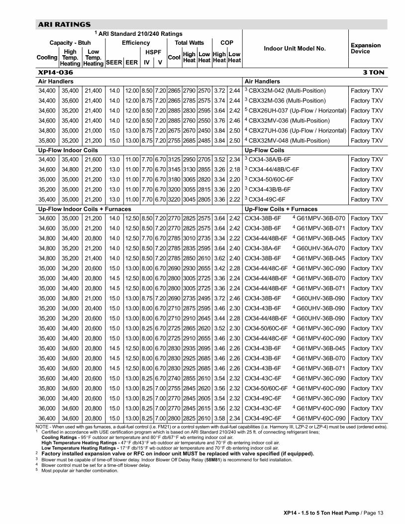
XP14−036 3 TON
Air Handlers Air Handlers
34,400 35,400 21,400 14.0 12.00 8.50 7.20 2865 2790 2570 3.72 2.44 3 CBX32M−042 (Multi−Position) Factory TXV
34,400 35,600 21,400 14.0 12.00 8.75 7.20 2865 2785 2575 3.74 2.44 3 CBX32M−036 (Multi−Position) Factory TXV
34,600 35,200 21,400 14.0 12.00 8.50 7.20 2885 2830 2595 3.64 2.42 5 CBX26UH−037 (Up−Flow / Horizontal) Factory TXV
34,600 35,400 21,400 14.0 12.00 8.50 7.20 2885 2760 2550 3.76 2.46 4 CBX32MV−036 (Multi−Position) Factory TXV
34,800 35,000 21,000 15.0 13.00 8.75 7.20 2675 2670 2450 3.84 2.50 4 CBX27UH−036 (Up−Flow / Horizontal) Factory TXV
35,800 35,200 21,200 15.0 13.00 8.75 7.20 2755 2685 2485 3.84 2.50 4 CBX32MV−048 (Multi−Position) Factory TXV
Up−Flow Indoor Coils Up−Flow Coils
34,400 35,400 21,600 13.0 11.00 7.70 6.70 3125 2950 2705 3.52 2.34 3 CX34−38A/B−6F Factory TXV
34,600 34,800 21,200 13.0 11.00 7.70 6.70 3145 3130 2855 3.26 2.18 3 CX34−44/48B/C−6F Factory TXV
35,000 35,000 21,200 13.0 11.00 7.70 6.70 3180 3065 2820 3.34 2.20 3 CX34−50/60C−6F Factory TXV
35,200 35,000 21,200 13.0 11.00 7.70 6.70 3200 3055 2815 3.36 2.20 3 CX34−43B/B−6F Factory TXV
35,400 35,000 21,200 13.0 11.00 7.70 6.70 3220 3045 2805 3.36 2.22 3 CX34−49C−6F Factory TXV
Up−Flow Indoor Coils + Furnaces Up−Flow Coils + Furnaces
34,600 35,000 21,200 14.0 12.50 8.50 7.20 2770 2825 2575 3.64 2.42 CX34−38B−6F 4 G61MPV−36B−070 Factory TXV
34,600 35,000 21,200 14.0 12.50 8.50 7.20 2770 2825 2575 3.64 2.42 CX34−38B−6F 4 G61MPV−36B−071 Factory TXV
34,800 34,400 20,800 14.0 12.50 7.70 6.70 2785 3010 2735 3.34 2.22 CX34−44/48B−6F 4 G61MPV−36B−045 Factory TXV
34,800 35,200 21,200 14.0 12.50 8.50 7.20 2785 2835 2595 3.64 2.40 CX34−38A−6F 4 G60UHV−36A−070 Factory TXV
34,800 35,200 21,400 14.0 12.50 8.50 7.20 2785 2850 2610 3.62 2.40 CX34−38B−6F 4 G61MPV−36B−045 Factory TXV
35,000 34,200 20,600 15.0 13.00 8.00 6.70 2690 2930 2655 3.42 2.28 CX34−44/48C−6F 4 G61MPV−36C−090 Factory TXV
35,000 34,400 20,800 14.5 12.50 8.00 6.70 2800 3005 2725 3.36 2.24 CX34−44/48B−6F 4 G61MPV−36B−070 Factory TXV
35,000 34,400 20,800 14.5 12.50 8.00 6.70 2800 3005 2725 3.36 2.24 CX34−44/48B−6F 4 G61MPV−36B−071 Factory TXV
35,000 34,800 21,000 15.0 13.00 8.75 7.20 2690 2735 2495 3.72 2.46 CX34−38B−6F 4 G60UHV−36B−090 Factory TXV
35,200 34,000 20,400 15.0 13.00 8.00 6.70 2710 2875 2595 3.46 2.30 CX34−43B−6F 4 G60UHV−36B−090 Factory TXV
35,200 34,200 20,600 15.0 13.00 8.00 6.70 2710 2910 2645 3.44 2.28 CX34−44/48B−6F 4 G60UHV−36B−090 Factory TXV
35,400 34,400 20,600 15.0 13.00 8.25 6.70 2725 2865 2620 3.52 2.30 CX34−50/60C−6F 4 G61MPV−36C−090 Factory TXV
35,400 34,400 20,800 15.0 13.00 8.00 6.70 2725 2910 2655 3.46 2.30 CX34−44/48C−6F 4 G61MPV−60C−090 Factory TXV
35,400 34,600 20,800 14.5 12.50 8.00 6.70 2830 2935 2695 3.46 2.26 CX34−43B−6F 4 G61MPV−36B−045 Factory TXV
35,400 34,600 20,800 14.5 12.50 8.00 6.70 2830 2925 2685 3.46 2.26 CX34−43B−6F 4 G61MPV−36B−070 Factory TXV
35,400 34,600 20,800 14.5 12.50 8.00 6.70 2830 2925 2685 3.46 2.26 CX34−43B−6F 4 G61MPV−36B−071 Factory TXV
35,600 34,400 20,600 15.0 13.00 8.25 6.70 2740 2855 2610 3.54 2.32 CX34−43C−6F 4 G61MPV−36C−090 Factory TXV
35,800 34,600 20,800 15.0 13.00 8.25 7.00 2755 2845 2620 3.56 2.32 CX34−50/60C−6F 4 G61MPV−60C−090 Factory TXV
36,000 34,400 20,600 15.0 13.00 8.25 7.00 2770 2845 2605 3.54 2.32 CX34−49C−6F 4 G61MPV−36C−090 Factory TXV
36,000 34,600 20,800 15.0 13.00 8.25 7.00 2770 2845 2615 3.56 2.32 CX34−43C−6F 4 G61MPV−60C−090 Factory TXV
36,400 34,600 20,800 15.0 13.00 8.25 7.00 2800 2825 2610 3.58 2.34 CX34−49C−6F 4 G61MPV−60C−090 Factory TXV
NOTE − When used with gas furnaces, a dual−fuel control (i.e. FM21) or a control system with dual−fuel capabilities (i.e. Harmony III, LZP−2 or LZP−4) must be used (ordered extra).1 Certified in accordance with USE certification program which is based on ARI Standard 210/240 with 25 ft. of connecting refrigerant lines;
Cooling Ratings − 95�F outdoor air temperature and 80�F db/67�F wb entering indoor coil air.High Temperature Heating Ratings − 47�F db/43�F wb outdoor air temperature and 70�F db entering indoor coil air.Low Temperature Heating Ratings − 17�F db/15�F wb outdoor air temperature and 70�F db entering indoor coil air.
2 Factory installed expansion valve or RFC on indoor unit MUST be replaced with valve specified (if equipped).3 Blower must be capable of time−off blower delay. Indoor Blower Off Delay Relay (58M81) is recommend for field installation.4 Blower control must be set for a time−off blower delay.5 Most popular air handler combination.

XP14 − 1.5 to 5 Ton Heat Pump / Page 14
ARI RATINGS
1 ARI Standard 210/240 Ratings
Capacity − Btuh Efficiency Total Watts COPI d U it M d l N
Expansion
CoolingHigh
TempLow
TempHSPF
CoolHigh Low High Low
Indoor Unit Model No.ExpansionDevice
Cooling Temp.Heating
Temp.Heating SEER EER IV V
CoolHighHeat
LowHeat
HighHeat
LowHeat
XP14−036 3 TON
Down−Flow Indoor Coils Down−Flow Coils
33,800 35,200 21,400 13.0 11.00 7.70 6.70 3075 2980 2730 3.46 2.30 3 CR33−48B/C−F 2 49L25
34,800 35,600 21,600 13.0 11.00 7.70 6.70 3165 2875 2655 3.62 2.38 3 CR33−50/60C−F 2 49L25
Down−Flow Indoor Coils + Furnaces Down−Flow Coils + Furnaces
34,400 34,600 20,800 14.5 12.50 8.50 7.00 2750 2765 2515 3.66 2.42 CR33−48B−F 4 G60DFV−36B−090 2 49L25
34,200 34,800 21,000 14.0 12.50 8.25 7.00 2735 2860 2605 3.56 2.36 CR33−48B−F 4 G61MPV−36B−045 2 49L25
34,200 34,800 21,000 14.0 12.50 8.25 7.00 2735 2855 2600 3.58 2.36 CR33−48B−F 4 G61MPV−36B−070 2 49L25
34,200 34,800 21,000 14.0 12.50 8.25 7.00 2735 2855 2600 3.58 2.36 CR33−48B−F 4 G61MPV−36B−071 2 49L25
34,400 34,600 20,800 14.5 12.50 8.50 7.00 2750 2780 2525 3.64 2.42 CR33−48C−F 4 G61MPV−36C−090 2 49L25
34,600 34,800 21,000 14.5 12.50 8.50 7.20 2770 2770 2535 3.68 2.42 CR33−48C−F 4 G61MPV−60C−090 2 49L25
35,600 34,600 20,600 16.0 13.50 9.00 7.50 2635 2545 2330 3.98 2.58 CR33−50/60C−F 4 G61MPV−36C−090 2 49L25
36,000 35,000 20,800 16.0 13.50 9.00 7.50 2665 2545 2340 4.04 2.60 CR33−50/60C−F 4 G61MPV−60C−090 2 49L25
Horizontal Indoor Coils Horizontal Coils
35,000 35,200 21,400 13.0 11.00 7.70 6.70 3180 3015 2795 3.42 2.24 3 CH33−44/48B−2F 2 49L25
35,200 35,000 21,200 13.0 11.00 7.70 6.70 3200 3050 2815 3.36 2.20 3 CH33−43C−2F 2 49L25
35,400 35,200 21,400 13.0 11.00 7.70 6.70 3220 3020 2800 3.42 2.24 3 CH33−50/60C−2F 2 49L25
35,600 35,200 21,400 13.0 11.00 7.70 6.70 3235 2995 2770 3.44 2.26 3 CH33−43B−2F 2 49L25
35,600 35,200 21,400 13.0 11.00 7.70 6.70 3235 3020 2800 3.42 2.24 3 CH33−49C−2F 2 49L25
Horizontal Indoor Coils + Furnaces Horizontal Coils + Furnaces
35,200 34,800 21,000 14.0 12.50 8.20 6.70 2815 2930 2705 3.48 2.28 CH33−44/48B−2F 4 G61MPV−36B−045 2 49L25
35,200 34,800 21,000 14.0 12.50 8.20 6.70 2815 2920 2700 3.50 2.28 CH33−44/48B−2F 4 G61MPV−36B−070 2 49L25
35,200 34,800 21,000 14.0 12.50 8.20 6.70 2815 2920 2700 3.50 2.28 CH33−44/48B−2F 4 G61MPV−36B−071 2 49L25
35,400 34,600 20,800 15.0 13.00 8.25 7.00 2725 2835 2625 3.58 2.32 CH33−44/48B−2F 4 G60UHV−36B−090 2 49L25
35,600 34,600 20,800 14.5 13.00 8.00 6.70 2740 2925 2685 3.46 2.26 CH33−43C−2F 4 G61MPV−36B−071 2 49L25
35,800 35,000 21,200 14.5 12.50 8.25 6.70 2865 2910 2680 3.52 2.32 CH33−43B−2F 4 G61MPV−36B−045 2 49L25
36,000 34,400 20,600 15.0 13.00 8.25 7.00 2770 2820 2595 3.58 2.32 CH33−50/60C−2F 4 G61MPV−36C−090 2 49L25
36,000 34,600 20,600 15.0 13.00 8.25 7.00 2770 2820 2600 3.60 2.32 CH33−49C−2F 4 G61MPV−36C−090 2 49L25
36,000 35,000 21,000 14.5 13.00 8.25 7.00 2770 2900 2670 3.54 2.30 CH33−43B−2F 4 G61MPV−36B−070 2 49L25
36,200 34,800 20,800 15.0 13.00 8.50 7.00 2785 2805 2600 3.64 2.34 CH33−50/60C−2F 4 G61MPV−60C−090 2 49L25
36,200 34,800 21,000 15.0 13.00 8.50 7.00 2785 2815 2595 3.62 2.36 CH33−43B−2F 4 G60UHV−36B−090 2 49L25
36,400 34,800 20,800 15.0 13.00 8.50 7.00 2800 2800 2600 3.64 2.34 CH33−49C−2F 4 G61MPV−60C−090 2 49L25
NOTE − When used with gas furnaces, a dual−fuel control (i.e. FM21) or a control system with dual−fuel capabilities (i.e. Harmony III, LZP−2 or LZP−4) must be used (ordered extra).1 Certified in accordance with USE certification program which is based on ARI Standard 210/240 with 25 ft. of connecting refrigerant lines;
Cooling Ratings − 95�F outdoor air temperature and 80�F db/67�F wb entering indoor coil air.High Temperature Heating Ratings − 47�F db/43�F wb outdoor air temperature and 70�F db entering indoor coil air.Low Temperature Heating Ratings − 17�F db/15�F wb outdoor air temperature and 70�F db entering indoor coil air.
2 Factory installed expansion valve or RFC on indoor unit MUST be replaced with valve specified (if equipped).3 Blower must be capable of time−off blower delay. Indoor Blower Off Delay Relay (58M81) is recommend for field installation.4 Blower control must be set for a time−off blower delay.5 Most popular air handler combination.

XP14 − 1.5 to 5 Ton Heat Pump / Page 15
ARI RATINGS
1 ARI Standard 210/240 Ratings
Capacity − Btuh Efficiency Total Watts COPI d U it M d l N
Expansion
CoolingHigh
TempLow
TempHSPF
CoolHigh Low High Low
Indoor Unit Model No.ExpansionDevice
Cooling Temp.Heating
Temp.Heating SEER EER IV V
CoolHighHeat
LowHeat
HighHeat
LowHeat
XP14−042 3.5 TON
Air Handlers Air Handlers
42,500 45,000 27,800 14.0 12.00 8.00 7.20 3540 3890 3540 3.40 2.30 3 CBX32M−048 (Multi−Position) Factory TXV
42,500 45,500 28,200 14.0 12.00 8.50 7.20 3540 3650 3320 3.66 2.48 5 CBX26UH−042 (Up−Flow / Horizontal) Factory TXV
43,500 44,500 27,400 15.0 13.00 8.50 7.20 3345 3735 3405 3.50 2.36 4 CBX27UH−042 (Up−Flow / Horizontal) Factory TXV
43,500 44,500 27,600 14.5 12.50 8.25 7.20 3480 3785 3465 3.44 2.34 4 CBX32MV−048 (Multi−Position) Factory TXV
Up−Flow Indoor Coils Up−Flow Coils
41,500 42,000 27,000 13.0 11.00 7.70 6.70 3775 3440 3145 3.58 2.52 3 CX34−60D−6F Factory TXV
42,000 42,000 26,800 13.0 11.00 7.70 6.70 3820 3475 3165 3.54 2.48 3 CX34−49C−6F Factory TXV
42,000 42,000 27,000 13.0 11.00 7.70 6.70 3820 3435 3120 3.58 2.54 3 CX34−62D−6F Factory TXV
42,500 42,500 27,200 13.0 11.00 7.70 6.70 3865 3350 3060 3.72 2.60 3 CX34−62C−6F Factory TXV
Up−Flow Indoor Coils + Furnaces Up−Flow Coils + Furnaces
42,000 41,000 26,000 15.0 12.50 9.00 7.70 3360 3230 2915 3.72 2.62 CX34−49C−6F 4 G60UHV−60C−090 Factory TXV
42,000 41,000 26,000 15.0 13.00 9.00 7.70 3230 3165 2865 3.80 2.66 CX34−60D−6F 4 G60UHV−60D−135 Factory TXV
42,000 41,000 26,200 14.5 12.50 8.75 7.50 3360 3310 2990 3.64 2.56 CX34−49C−6F 4 G61MPV−60C−091 Factory TXV
42,000 41,500 26,200 14.5 12.50 9.00 7.50 3360 3285 2975 3.70 2.58 CX34−49C−6F 4 G61MPV−60C−090 Factory TXV
42,000 41,500 26,400 14.0 12.50 9.00 7.50 3360 3315 3010 3.66 2.56 CX34−49C−6F 4 G61MPV−36C−090 Factory TXV
42,500 41,000 26,200 15.0 12.50 9.00 7.70 3400 3250 2945 3.70 2.60 CX34−49C−6F 4 G60UHV−60C−110 Factory TXV
42,500 41,000 26,200 15.0 13.00 9.25 7.70 3270 3160 2875 3.80 2.66 CX34−62D−6F 4 G60UHV−60D−135 Factory TXV
42,500 41,500 26,200 14.5 12.50 9.00 7.50 3400 3265 2960 3.72 2.60 CX34−49C−6F 4 G61MPV−60C−110 Factory TXV
42,500 41,500 26,200 14.5 12.50 9.00 7.50 3400 3275 2970 3.72 2.58 CX34−49C−6F 4 G61MPV−60C−111 Factory TXV
42,500 41,500 26,200 15.0 12.50 9.00 7.70 3400 3195 2920 3.80 2.62 CX34−60D−6F 4 G61MPV−60D−135 Factory TXV
42,500 41,500 26,200 15.0 13.00 9.00 7.70 3270 3190 2915 3.82 2.64 CX34−62D−6F 4 G61MPV−60D−135 Factory TXV
42,500 41,500 26,400 15.0 12.50 9.25 7.70 3400 3180 2885 3.82 2.68 CX34−62C−6F 4 G61MPV−60C−091 Factory TXV
43,000 41,500 26,200 15.0 13.00 9.25 8.00 3310 3105 2810 3.92 2.74 CX34−62C−6F 4 G60UHV−60C−090 Factory TXV
43,000 41,500 26,400 15.0 13.00 9.25 7.70 3310 3130 2840 3.88 2.72 CX34−62C−6F 4 G60UHV−60C−110 Factory TXV
43,000 42,000 26,400 15.0 12.50 9.25 7.70 3440 3160 2870 3.90 2.70 CX34−62C−6F 4 G61MPV−60C−090 Factory TXV
43,000 42,000 26,600 14.5 12.50 9.00 7.70 3440 3190 2905 3.86 2.68 CX34−62C−6F 4 G61MPV−36C−090 Factory TXV
43,000 42,000 26,600 15.0 12.50 9.25 8.00 3440 3140 2880 3.92 2.70 CX34−62C−6F 4 G61MPV−60C−110 Factory TXV
43,000 42,000 26,600 15.0 12.50 9.25 8.00 3440 3150 2895 3.90 2.70 CX34−62C−6F 4 G61MPV−60C−111 Factory TXV
Down−Flow Indoor Coils Down−Flow Coils
41,500 42,500 27,200 13.0 11.00 7.70 6.70 3775 3340 3055 3.72 2.60 3 CR33−50/60C−F 2 49L25
41,500 42,500 27,200 13.0 11.00 7.70 6.70 3775 3340 3055 3.72 2.60 3 CR33−60D−F 2 49L25
Down−Flow Indoor Coils + Furnaces Down−Flow Coils + Furnaces
41,500 41,500 26,200 15.0 12.50 9.50 8.00 3320 3100 2805 3.92 2.74 CR33−50/60C−F 4 G60DFV−60C−110 2 49L25
41,500 41,500 26,200 15.0 12.50 9.50 8.00 3320 3085 2790 3.94 2.74 CR33−60D−F 4 G60DFV−60D−135 2 49L25
41,500 41,500 26,400 14.0 12.50 9.25 7.70 3320 3170 2875 3.84 2.68 CR33−50/60C−F 4 G61MPV−60C−091 2 49L25
41,500 42,000 26,400 14.5 12.50 9.25 7.70 3320 3150 2860 3.90 2.70 CR33−50/60C−F 4 G61MPV−60C−090 2 49L25
41,500 42,000 26,600 14.0 12.00 9.25 7.70 3460 3180 2895 3.88 2.70 CR33−50/60C−F 4 G61MPV−36C−090 2 49L25
42,000 41,500 26,200 15.0 12.50 9.50 8.00 3360 3080 2795 3.94 2.74 CR33−50/60C−F 4 G60DFV−60C−090 2 49L25
42,000 41,500 26,400 15.0 12.50 9.50 8.00 3360 3095 2815 3.92 2.74 CR33−60D−F 4 G61MPV−60D−135 2 49L25
42,000 42,000 26,400 14.5 12.50 9.50 8.00 3360 3125 2845 3.94 2.72 CR33−50/60C−F 4 G61MPV−60C−110 2 49L25
42,000 42,000 26,600 14.5 12.50 9.25 8.00 3360 3140 2860 3.92 2.72 CR33−50/60C−F 4 G61MPV−60C−111 2 49L25
NOTE − When used with gas furnaces, a dual−fuel control (i.e. FM21) or a control system with dual−fuel capabilities (i.e. Harmony III, LZP−2 or LZP−4) must be used (ordered extra).1 Certified in accordance with USE certification program which is based on ARI Standard 210/240 with 25 ft. of connecting refrigerant lines;
Cooling Ratings − 95�F outdoor air temperature and 80�F db/67�F wb entering indoor coil air.High Temperature Heating Ratings − 47�F db/43�F wb outdoor air temperature and 70�F db entering indoor coil air.Low Temperature Heating Ratings − 17�F db/15�F wb outdoor air temperature and 70�F db entering indoor coil air.
2 Factory installed expansion valve or RFC on indoor unit MUST be replaced with valve specified (if equipped).3 Blower must be capable of time−off blower delay. Indoor Blower Off Delay Relay (58M81) is recommend for field installation.4 Blower control must be set for a time−off blower delay.5 Most popular air handler combination.
XP14 − 1.5 to 5 Ton Heat Pump / Page 16
ARI RATINGS
1 ARI Standard 210/240 Ratings
Capacity − Btuh Efficiency Total Watts COPI d U it M d l N
Expansion
CoolingHigh
TempLow
TempHSPF
CoolHigh Low High Low
Indoor Unit Model No.ExpansionDevice
Cooling Temp.Heating
Temp.Heating SEER EER IV V
CoolHighHeat
LowHeat
HighHeat
LowHeat
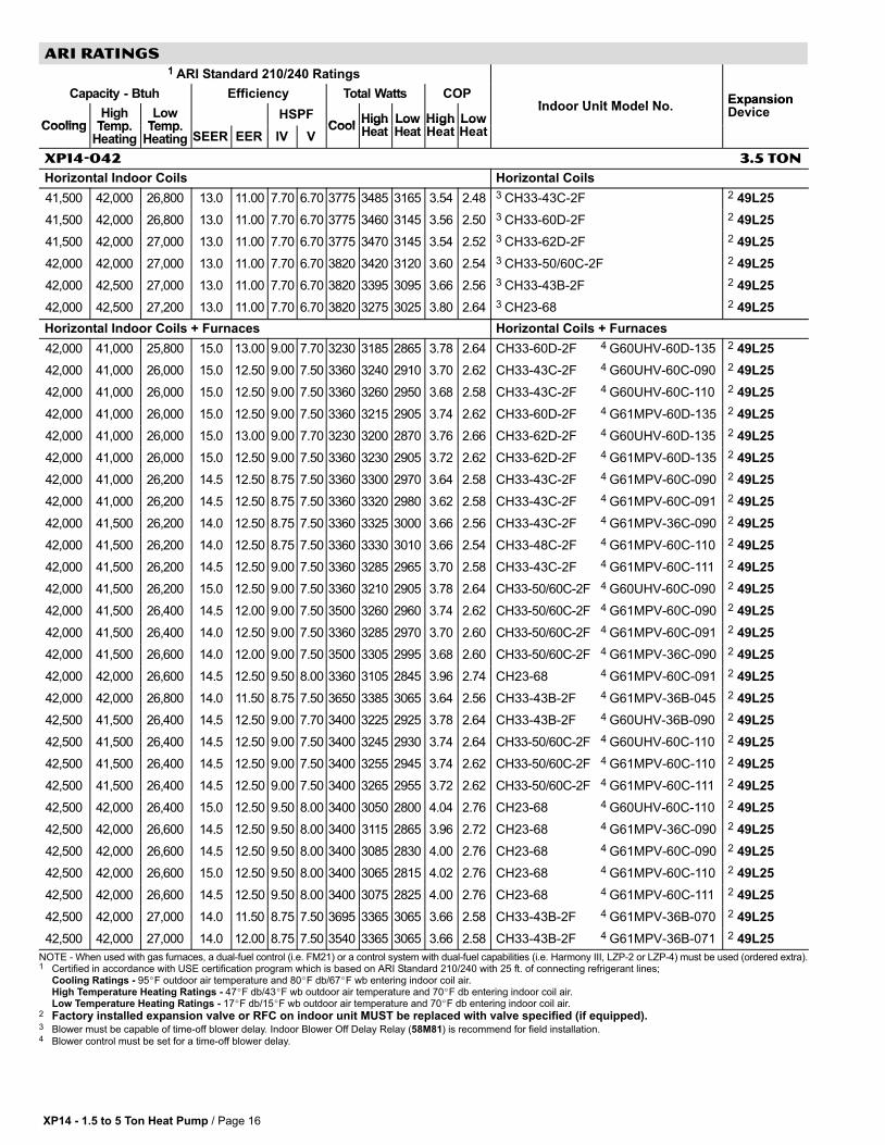
XP14−042 3.5 TON
Horizontal Indoor Coils Horizontal Coils
41,500 42,000 26,800 13.0 11.00 7.70 6.70 3775 3485 3165 3.54 2.48 3 CH33−43C−2F 2 49L25
41,500 42,000 26,800 13.0 11.00 7.70 6.70 3775 3460 3145 3.56 2.50 3 CH33−60D−2F 2 49L25
41,500 42,000 27,000 13.0 11.00 7.70 6.70 3775 3470 3145 3.54 2.52 3 CH33−62D−2F 2 49L25
42,000 42,000 27,000 13.0 11.00 7.70 6.70 3820 3420 3120 3.60 2.54 3 CH33−50/60C−2F 2 49L25
42,000 42,500 27,000 13.0 11.00 7.70 6.70 3820 3395 3095 3.66 2.56 3 CH33−43B−2F 2 49L25
42,000 42,500 27,200 13.0 11.00 7.70 6.70 3820 3275 3025 3.80 2.64 3 CH23−68 2 49L25
Horizontal Indoor Coils + Furnaces Horizontal Coils + Furnaces
42,000 41,000 25,800 15.0 13.00 9.00 7.70 3230 3185 2865 3.78 2.64 CH33−60D−2F 4 G60UHV−60D−135 2 49L25
42,000 41,000 26,000 15.0 12.50 9.00 7.50 3360 3240 2910 3.70 2.62 CH33−43C−2F 4 G60UHV−60C−090 2 49L25
42,000 41,000 26,000 15.0 12.50 9.00 7.50 3360 3260 2950 3.68 2.58 CH33−43C−2F 4 G60UHV−60C−110 2 49L25
42,000 41,000 26,000 15.0 12.50 9.00 7.50 3360 3215 2905 3.74 2.62 CH33−60D−2F 4 G61MPV−60D−135 2 49L25
42,000 41,000 26,000 15.0 13.00 9.00 7.70 3230 3200 2870 3.76 2.66 CH33−62D−2F 4 G60UHV−60D−135 2 49L25
42,000 41,000 26,000 15.0 12.50 9.00 7.50 3360 3230 2905 3.72 2.62 CH33−62D−2F 4 G61MPV−60D−135 2 49L25
42,000 41,000 26,200 14.5 12.50 8.75 7.50 3360 3300 2970 3.64 2.58 CH33−43C−2F 4 G61MPV−60C−090 2 49L25
42,000 41,000 26,200 14.5 12.50 8.75 7.50 3360 3320 2980 3.62 2.58 CH33−43C−2F 4 G61MPV−60C−091 2 49L25
42,000 41,500 26,200 14.0 12.50 8.75 7.50 3360 3325 3000 3.66 2.56 CH33−43C−2F 4 G61MPV−36C−090 2 49L25
42,000 41,500 26,200 14.0 12.50 8.75 7.50 3360 3330 3010 3.66 2.54 CH33−48C−2F 4 G61MPV−60C−110 2 49L25
42,000 41,500 26,200 14.5 12.50 9.00 7.50 3360 3285 2965 3.70 2.58 CH33−43C−2F 4 G61MPV−60C−111 2 49L25
42,000 41,500 26,200 15.0 12.50 9.00 7.50 3360 3210 2905 3.78 2.64 CH33−50/60C−2F 4 G60UHV−60C−090 2 49L25
42,000 41,500 26,400 14.5 12.00 9.00 7.50 3500 3260 2960 3.74 2.62 CH33−50/60C−2F 4 G61MPV−60C−090 2 49L25
42,000 41,500 26,400 14.0 12.50 9.00 7.50 3360 3285 2970 3.70 2.60 CH33−50/60C−2F 4 G61MPV−60C−091 2 49L25
42,000 41,500 26,600 14.0 12.00 9.00 7.50 3500 3305 2995 3.68 2.60 CH33−50/60C−2F 4 G61MPV−36C−090 2 49L25
42,000 42,000 26,600 14.5 12.50 9.50 8.00 3360 3105 2845 3.96 2.74 CH23−68 4 G61MPV−60C−091 2 49L25
42,000 42,000 26,800 14.0 11.50 8.75 7.50 3650 3385 3065 3.64 2.56 CH33−43B−2F 4 G61MPV−36B−045 2 49L25
42,500 41,500 26,400 14.5 12.50 9.00 7.70 3400 3225 2925 3.78 2.64 CH33−43B−2F 4 G60UHV−36B−090 2 49L25
42,500 41,500 26,400 14.5 12.50 9.00 7.50 3400 3245 2930 3.74 2.64 CH33−50/60C−2F 4 G60UHV−60C−110 2 49L25
42,500 41,500 26,400 14.5 12.50 9.00 7.50 3400 3255 2945 3.74 2.62 CH33−50/60C−2F 4 G61MPV−60C−110 2 49L25
42,500 41,500 26,400 14.5 12.50 9.00 7.50 3400 3265 2955 3.72 2.62 CH33−50/60C−2F 4 G61MPV−60C−111 2 49L25
42,500 42,000 26,400 15.0 12.50 9.50 8.00 3400 3050 2800 4.04 2.76 CH23−68 4 G60UHV−60C−110 2 49L25
42,500 42,000 26,600 14.5 12.50 9.50 8.00 3400 3115 2865 3.96 2.72 CH23−68 4 G61MPV−36C−090 2 49L25
42,500 42,000 26,600 14.5 12.50 9.50 8.00 3400 3085 2830 4.00 2.76 CH23−68 4 G61MPV−60C−090 2 49L25
42,500 42,000 26,600 15.0 12.50 9.50 8.00 3400 3065 2815 4.02 2.76 CH23−68 4 G61MPV−60C−110 2 49L25
42,500 42,000 26,600 14.5 12.50 9.50 8.00 3400 3075 2825 4.00 2.76 CH23−68 4 G61MPV−60C−111 2 49L25
42,500 42,000 27,000 14.0 11.50 8.75 7.50 3695 3365 3065 3.66 2.58 CH33−43B−2F 4 G61MPV−36B−070 2 49L25
42,500 42,000 27,000 14.0 12.00 8.75 7.50 3540 3365 3065 3.66 2.58 CH33−43B−2F 4 G61MPV−36B−071 2 49L25
NOTE − When used with gas furnaces, a dual−fuel control (i.e. FM21) or a control system with dual−fuel capabilities (i.e. Harmony III, LZP−2 or LZP−4) must be used (ordered extra).1 Certified in accordance with USE certification program which is based on ARI Standard 210/240 with 25 ft. of connecting refrigerant lines;
Cooling Ratings − 95�F outdoor air temperature and 80�F db/67�F wb entering indoor coil air.High Temperature Heating Ratings − 47�F db/43�F wb outdoor air temperature and 70�F db entering indoor coil air.Low Temperature Heating Ratings − 17�F db/15�F wb outdoor air temperature and 70�F db entering indoor coil air.
2 Factory installed expansion valve or RFC on indoor unit MUST be replaced with valve specified (if equipped).3 Blower must be capable of time−off blower delay. Indoor Blower Off Delay Relay (58M81) is recommend for field installation.4 Blower control must be set for a time−off blower delay.

XP14 − 1.5 to 5 Ton Heat Pump / Page 17
ARI RATINGS
1 ARI Standard 210/240 Ratings
Capacity − Btuh Efficiency Total Watts COPI d U it M d l N
Expansion
CoolingHigh
TempLow
TempHSPF
CoolHigh Low High Low
Indoor Unit Model No.ExpansionDevice
Cooling Temp.Heating
Temp.Heating SEER EER IV V
CoolHighHeat
LowHeat
HighHeat
LowHeat
XP14−048 4 TON
Air Handlers Air Handlers
48,500 46,500 29,800 14.5 12.00 8.50 7.20 4040 3830 3505 3.56 2.48 4 CBX32MV−068 (Multi−Position) Factory TXV
48,500 46,500 30,000 14.0 12.00 8.75 7.20 4040 3765 3465 3.62 2.54 4 CBX32MV−060 (Multi−Position) Factory TXV
48,500 47,000 29,200 15.0 12.50 8.50 7.20 3880 3930 3540 3.50 2.42 4 CBX27UH−048 (Up−Flow / Horizontal) Factory TXV
49,000 47,000 30,200 14.0 12.00 8.50 7.20 4085 3820 3505 3.60 2.52 5 CBX26UH−048 (Up−Flow / Horizontal) Factory TXV
Up−Flow Indoor Coils Up−Flow Coils
48,500 47,000 30,400 13.0 11.00 7.70 6.70 4410 3995 3675 3.44 2.42 3 CX34−49C−6F Factory TXV
48,500 47,000 30,400 13.0 11.00 7.70 6.70 4410 3975 3660 3.46 2.44 3 CX34−60D−6F Factory TXV
48,500 47,000 30,400 13.0 11.00 7.70 6.70 4410 3945 3625 3.50 2.46 3 CX34−62D−6F Factory TXV
49,500 47,500 30,600 13.0 11.00 7.70 6.70 4500 3850 3555 3.62 2.52 3 CX34−62C−6F Factory TXV
Up−Flow Indoor Coils + Furnaces Up−Flow Coils + Furnaces
49,000 46,000 29,600 15.0 12.50 8.50 7.20 3920 3805 3475 3.54 2.50 CX34−60D−6F 4 G60UHV−60D−135 Factory TXV
49,000 46,000 29,800 14.5 12.50 8.50 7.20 3920 3835 3520 3.52 2.48 CX34−60D−6F 4 G61MPV−60D−135 Factory TXV
49,000 46,500 29,800 14.0 12.50 8.50 7.20 3920 3835 3520 3.56 2.48 CX34−49C−6F 4 G60UHV−60C−110 Factory TXV
49,000 46,500 30,000 14.0 12.00 8.50 7.20 4085 3875 3555 3.52 2.48 CX34−49C−6F 4 G61MPV−60C−090 Factory TXV
49,000 46,500 30,000 14.0 12.00 8.50 7.20 4085 3875 3555 3.52 2.48 CX34−49C−6F 4 G61MPV−60C−110 Factory TXV
49,000 46,500 30,000 14.0 12.00 8.50 7.20 4085 3880 3560 3.52 2.46 CX34−49C−6F 4 G61MPV−60C−111 Factory TXV
49,000 46,500 30,200 14.0 12.00 8.25 7.20 4085 3920 3610 3.48 2.44 CX34−49C−6F 4 G61MPV−60C−091 Factory TXV
49,500 46,000 29,600 15.0 12.50 8.50 7.20 3960 3765 3440 3.58 2.52 CX34−62D−6F 4 G60UHV−60D−135 Factory TXV
49,500 46,500 29,800 14.5 12.50 8.50 7.20 3960 3820 3510 3.56 2.48 CX34−49C−6F 4 G60UHV−60C−090 Factory TXV
49,500 46,500 29,800 14.5 12.50 8.50 7.20 3960 3805 3485 3.58 2.50 CX34−62D−6F 4 G61MPV−60D−135 Factory TXV
50,000 47,000 30,000 15.0 12.50 9.00 7.20 4000 3690 3395 3.74 2.58 CX34−62C−6F 4 G60UHV−60C−110 Factory TXV
50,000 47,000 30,200 15.0 12.50 9.00 7.20 4000 3690 3400 3.74 2.60 CX34−62C−6F 4 G60UHV−60C−090 Factory TXV
50,000 47,000 30,200 14.5 12.50 8.75 7.20 4000 3735 3445 3.68 2.56 CX34−62C−6F 4 G61MPV−60C−090 Factory TXV
50,000 47,000 30,200 14.5 12.50 8.75 7.20 4000 3725 3435 3.70 2.58 CX34−62C−6F 4 G61MPV−60C−110 Factory TXV
50,000 47,000 30,200 14.5 12.50 8.75 7.20 4000 3730 3440 3.70 2.58 CX34−62C−6F 4 G61MPV−60C−111 Factory TXV
50,000 47,500 30,400 14.0 12.00 8.75 7.20 4165 3775 3490 3.68 2.56 CX34−62C−6F 4 G61MPV−60C−091 Factory TXV
Down−Flow Indoor Coils Down−Flow Coils
47,500 47,500 30,600 13.0 11.00 7.70 6.70 4320 3855 3555 3.62 2.52 3 CR33−50/60C−F 2 91M02
47,500 47,500 30,600 13.0 11.00 7.70 6.70 4320 3855 3555 3.62 2.52 3 CR33−60D−F 2 91M02
NOTE − When used with gas furnaces, a dual−fuel control (i.e. FM21) or a control system with dual−fuel capabilities (i.e. Harmony III, LZP−2 or LZP−4) must be used (ordered extra).1 Certified in accordance with USE certification program which is based on ARI Standard 210/240 with 25 ft. of connecting refrigerant lines;
Cooling Ratings − 95�F outdoor air temperature and 80�F db/67�F wb entering indoor coil air.High Temperature Heating Ratings − 47�F db/43�F wb outdoor air temperature and 70�F db entering indoor coil air.Low Temperature Heating Ratings − 17�F db/15�F wb outdoor air temperature and 70�F db entering indoor coil air.
2 Factory installed expansion valve or RFC on indoor unit MUST be replaced with valve specified (if equipped).3 Blower must be capable of time−off blower delay. Indoor Blower Off Delay Relay (58M81) is recommend for field installation.4 Blower control must be set for a time−off blower delay.5 Most popular air handler combination.

XP14 − 1.5 to 5 Ton Heat Pump / Page 18
ARI RATINGS
1 ARI Standard 210/240 Ratings
Capacity − Btuh Efficiency Total Watts COPI d U it M d l N
Expansion
CoolingHigh
TempLow
TempHSPF
CoolHigh Low High Low
Indoor Unit Model No.ExpansionDevice
Cooling Temp.Heating
Temp.Heating SEER EER IV V
CoolHighHeat
LowHeat
HighHeat
LowHeat
XP14−048 4 TON
Down−Flow Indoor Coils + Furnaces Down−Flow Coils + Furnaces
48,000 46,500 29,800 14.5 12.50 8.75 7.20 3840 3665 3345 3.72 2.60 CR33−60D−F 4 G60DFV−60D−135 2 91M02
48,000 46,500 30,000 14.0 12.00 8.75 7.20 4000 3665 3355 3.72 2.62 CR33−50/60C−F 4 G60DFV−60C−090 2 91M02
48,000 47,000 30,200 14.0 12.00 8.75 7.20 4000 3745 3445 3.68 2.56 CR33−50/60C−F 4 G61MPV−60C−090 2 91M02
48,000 47,000 30,200 14.0 12.00 8.75 7.20 4000 3735 3435 3.68 2.58 CR33−50/60C−F 4 G61MPV−60C−110 2 91M02
48,000 47,000 30,200 14.0 12.00 8.75 7.20 4000 3740 3440 3.68 2.58 CR33−50/60C−F 4 G61MPV−60C−111 2 91M02
48,000 47,000 30,400 13.0 11.00 7.70 7.00 4365 3785 3490 3.64 2.56 CR33−50/60C−F 4 G61MPV−60C−091 2 91M02
48,500 47,000 30,000 14.0 12.00 8.75 7.20 4040 3690 3385 3.74 2.60 CR33−60D−F 4 G61MPV−60D−135 2 91M02
48,500 47,000 30,200 14.0 12.00 8.75 7.20 4040 3680 3385 3.74 2.62 CR33−50/60C−F 4 G60DFV−60C−110 2 91M02
Horizontal Indoor Coils Horizontal Coils
48,000 46,500 30,400 13.0 11.00 7.70 6.70 4365 4005 3675 3.40 2.42 3 CH33−60D−2F 2 91M02
48,500 47,000 30,400 13.0 11.00 7.70 6.70 4410 3965 3645 3.48 2.44 3 CH33−50/60C−2F 2 91M02
48,500 47,000 30,400 13.0 11.00 7.70 6.70 4410 3995 3655 3.44 2.44 3 CH33−62D−2F 2 91M02
49,000 48,000 30,800 13.0 11.00 7.70 6.70 4455 3775 3510 3.72 2.56 3 CH23−68 2 91M02
Horizontal Indoor Coils + Furnaces Horizontal Coils + Furnaces
48,500 46,000 29,600 14.5 12.50 8.50 7.20 3880 3800 3465 3.54 2.50 CH33−60D−2F 4 G60UHV−60D−135 2 91M02
48,500 46,000 29,800 14.0 12.00 8.50 7.20 4040 3835 3505 3.52 2.48 CH33−60D−2F 4 G61MPV−60D−135 2 91M02
49,000 46,000 29,600 14.5 12.50 8.50 7.20 3920 3790 3445 3.56 2.52 CH33−62D−2F 4 G60UHV−60D−135 2 91M02
49,000 46,000 29,800 14.0 12.50 8.50 7.20 3920 3825 3485 3.52 2.50 CH33−62D−2F 4 G61MPV−60D−135 2 91M02
49,000 46,500 30,000 14.0 12.00 8.50 7.20 4085 3820 3505 3.56 2.50 CH33−50/60C−2F 4 G60UHV−60C−090 2 91M02
49,000 46,500 30,000 14.0 12.00 8.50 7.20 4085 3840 3520 3.54 2.50 CH33−50/60C−2F 4 G60UHV−60C−110 2 91M02
49,000 46,500 30,200 14.0 12.00 8.50 7.20 4085 3880 3560 3.52 2.48 CH33−50/60C−2F 4 G61MPV−60C−090 2 91M02
49,000 46,500 30,200 14.0 12.00 8.50 7.20 4085 3875 3555 3.52 2.48 CH33−50/60C−2F 4 G61MPV−60C−110 2 91M02
49,000 46,500 30,200 14.0 12.00 8.50 7.20 4085 3880 3560 3.52 2.48 CH33−50/60C−2F 4 G61MPV−60C−111 2 91M02
49,000 47,000 30,400 14.0 12.00 8.50 7.20 4085 3915 3600 3.52 2.48 CH33−50/60C−2F 4 G61MPV−60C−091 2 91M02
49,500 47,000 30,000 15.0 12.50 9.00 7.20 3960 3565 3315 3.86 2.66 CH23−68 4 G60UHV−60C−090 2 91M02
49,500 47,000 30,000 14.5 12.50 9.00 7.20 3960 3585 3320 3.84 2.64 CH23−68 4 G60UHV−60C−110 2 91M02
49,500 47,000 30,000 15.0 12.50 9.00 7.20 3960 3575 3310 3.86 2.66 CH23−68 4 G61MPV−60D−135 2 91M02
49,500 47,000 30,200 14.5 12.50 9.00 7.20 3960 3625 3360 3.80 2.64 CH23−68 4 G61MPV−60C−090 2 91M02
49,500 47,000 30,200 14.5 12.50 9.00 7.20 3960 3610 3345 3.82 2.64 CH23−68 4 G61MPV−60C−110 2 91M02
49,500 47,500 30,200 14.5 12.50 9.00 7.20 3960 3625 3360 3.84 2.64 CH23−68 4 G61MPV−60C−111 2 91M02
49,500 47,500 30,400 14.0 12.00 9.00 7.20 4125 3665 3410 3.80 2.62 CH23−68 4 G61MPV−60C−091 2 91M02
50,000 47,000 29,800 15.0 13.00 9.00 7.50 3845 3530 3290 3.90 2.66 CH23−68 4 G60UHV−60D−135 2 91M02
NOTE − When used with gas furnaces, a dual−fuel control (i.e. FM21) or a control system with dual−fuel capabilities (i.e. Harmony III, LZP−2 or LZP−4) must be used (ordered extra).1 Certified in accordance with USE certification program which is based on ARI Standard 210/240 with 25 ft. of connecting refrigerant lines;
Cooling Ratings − 95�F outdoor air temperature and 80�F db/67�F wb entering indoor coil air.High Temperature Heating Ratings − 47�F db/43�F wb outdoor air temperature and 70�F db entering indoor coil air.Low Temperature Heating Ratings − 17�F db/15�F wb outdoor air temperature and 70�F db entering indoor coil air.
2 Factory installed expansion valve or RFC on indoor unit MUST be replaced with valve specified (if equipped).3 Blower must be capable of time−off blower delay. Indoor Blower Off Delay Relay (58M81) is recommend for field installation.4 Blower control must be set for a time−off blower delay.5 Most popular air handler combination.

XP14 − 1.5 to 5 Ton Heat Pump / Page 19
ARI RATINGS
1 ARI Standard 210/240 Ratings
Capacity − Btuh Efficiency Total Watts COPI d U it M d l N
Expansion
CoolingHigh
TempLow
TempHSPF
CoolHigh Low High Low
Indoor Unit Model No.ExpansionDevice
Cooling Temp.Heating
Temp.Heating SEER EER IV V
CoolHighHeat
LowHeat
HighHeat
LowHeat
XP14−060 5 TON
Air Handlers Air Handlers
56,000 55,000 35,600 14.0 11.50 8.75 7.50 4870 4640 4135 3.48 2.52 4 CBX32MV−048 (Multi−Position) Factory TXV
56,500 54,500 35,400 14.0 11.50 8.25 7.20 4915 4840 4305 3.30 2.40 4 CBX32MV−068 (Multi−Position) Factory TXV
56,500 55,000 35,800 14.0 11.50 8.75 7.50 4915 4665 4195 3.46 2.50 3 CBX32M−060 (Multi−Position) Factory TXV
56,500 55,000 35,800 14.0 11.50 8.50 7.50 4915 4680 4215 3.44 2.48 4 CBX32MV−060 (Multi−Position) Factory TXV
58,500 55,000 35,800 14..00 12.00 8.75 7.50 4875 4610 4120 3.50 2.54 5 CBX26UH−060 (Up−Flow / Horizontal) Factory TXV
59,000 55,500 36,000 15.0 12.50 8.75 7.70 4720 4585 4055 3.54 2.60 4 CBX27UH−060 (Up−Flow / Horizontal) Factory TXV
Up−Flow Indoor Coils Up−Flow Coils
57,000 54,500 35,800 13.0 11.00 7.70 6.70 5180 4955 4415 3.22 2.38 3 CX34−62D−6F Factory TXV
58,500 55,000 36,000 13.0 11.00 7.70 6.70 5320 4850 4325 3.32 2.44 3 CX34−62C−6F Factory TXV
Up−Flow Indoor Coils + Furnaces Up−Flow Coils + Furnaces
57,500 54,000 35,200 14.0 11.50 8.25 7.20 5000 4820 4270 3.28 2.42 CX34−62D−6F 4 G61MPV−60D−135 Factory TXV
58,000 54,500 35,800 14.0 11.50 8.50 7.50 5045 4835 4295 3.30 2.44 CX34−62C−6F 4 G61MPV−60C−090 Factory TXV
58,000 55,000 36,000 14.0 11.50 8.50 7.20 5045 4885 4355 3.30 2.42 CX34−62C−6F 4 G61MPV−60C−091 Factory TXV
58,500 54,500 35,400 14.5 12.00 8.50 7.20 4875 4725 4240 3.38 2.44 CX34−62D−6F 4 G60UHV−60D−135 Factory TXV
58,500 54,500 35,600 14.0 11.50 8.50 7.50 5085 4750 4220 3.36 2.48 CX34−62C−6F 4 G60UHV−60C−090 Factory TXV
58,500 54,500 35,600 14.0 11.50 8.50 7.50 5085 4765 4235 3.36 2.46 CX34−62C−6F 4 G60UHV−60C−110 Factory TXV
58,500 54,500 35,800 14.0 11.50 8.50 7.50 5085 4800 4270 3.32 2.46 CX34−62C−6F 4 G61MPV−60C−110 Factory TXV
58,500 55,000 35,800 14.0 11.50 8.50 7.50 5085 4815 4290 3.34 2.44 CX34−62C−6F 4 G61MPV−60C−111 Factory TXV
Horizontal Indoor Coils Horizontal Coils
56,500 54,500 35,600 13.0 11.00 7.70 6.70 5135 5005 4465 3.20 2.34 3 CH33−62D−2F 2 91M02
57,000 54,500 35,800 13.0 11.00 7.70 6.70 5180 4965 4405 3.22 2.38 3 CH33−50/60C−2F 2 91M02
57,500 55,500 36,200 13.0 11.00 7.70 6.70 5225 4615 4180 3.52 2.54 3 CH23−68 2 91M02
Horizontal Indoor Coils + Furnaces Horizontal Coils + Furnaces
56,500 54,500 35,800 13.5 11.00 8.25 7.20 5135 4985 4405 3.20 2.38 CH33−50/60C−2F 4 G61MPV−60C−090 2 91M02
57,000 54,500 35,600 14.0 11.50 8.25 7.20 4955 4900 4340 3.26 2.40 CH33−50/60C−2F 4 G60UHV−60C−090 2 91M02
57,000 54,500 35,600 14.0 11.50 8.25 7.20 4955 4920 4350 3.24 2.40 CH33−50/60C−2F 4 G60UHV−60C−110 2 91M02
57,000 54,500 35,800 13.5 11.00 8.25 7.20 5180 4950 4385 3.22 2.40 CH33−50/60C−2F 4 G61MPV−60C−110 2 91M02
57,000 54,500 35,800 13.5 11.00 8.25 7.20 5180 4960 4400 3.22 2.38 CH33−50/60C−2F 4 G61MPV−60C−111 2 91M02
57,000 54,500 36,000 13.5 11.00 8.25 7.20 5180 5030 4465 3.18 2.36 CH33−50/60C−2F 4 G61MPV−60C−091 2 91M02
57,500 54,500 35,800 14.0 11.50 8.25 7.20 5000 4875 4375 3.28 2.40 CH33−62D−2F 4 G61MPV−60D−135 2 91M02
57,500 55,500 35,800 14.0 11.50 8.75 7.50 5000 4560 4115 3.56 2.54 CH23−68 4 G61MPV−60C−090 2 91M02
57,500 55,500 35,800 14.0 11.50 8.75 7.50 5000 4535 4100 3.58 2.56 CH23−68 4 G61MPV−60C−110 2 91M02
57,500 55,500 36,000 14.0 11.50 8.75 7.50 5000 4620 4185 3.52 2.52 CH23−68 4 G61MPV−60C−091 2 91M02
57,500 55,500 36,000 14.0 11.50 8.75 7.50 5000 4550 4115 3.58 2.56 CH23−68 4 G61MPV−60C−111 2 91M02
58,000 54,000 35,400 14.0 12.00 8.50 7.20 4835 4760 4265 3.32 2.44 CH33−62D−2F 4 G60UHV−60D−135 2 91M02
58,000 55,000 35,600 14.0 11.50 8.75 7.70 5045 4475 4045 3.60 2.58 CH23−68 4 G60UHV−60C−090 2 91M02
58,000 55,000 35,600 14.0 12.00 8.75 7.50 4835 4475 4040 3.60 2.58 CH23−68 4 G61MPV−60D−135 2 91M02
58,500 55,500 35,800 14.5 12.00 9.00 7.50 4875 4405 3995 3.70 2.62 CH23−68 4 G60UHV−60D−135 2 91M02
58,500 56,000 36,200 14.0 11.50 8.75 7.50 5085 4525 4130 3.62 2.56 CH23−68 4 G60UHV−60C−110 2 91M02
NOTE − When used with gas furnaces, a dual−fuel control (i.e. FM21) or a control system with dual−fuel capabilities (i.e. Harmony III, LZP−2 or LZP−4) must be used (ordered extra).1 Certified in accordance with USE certification program which is based on ARI Standard 210/240 with 25 ft. of connecting refrigerant lines;
Cooling Ratings − 95�F outdoor air temperature and 80�F db/67�F wb entering indoor coil air.High Temperature Heating Ratings − 47�F db/43�F wb outdoor air temperature and 70�F db entering indoor coil air.Low Temperature Heating Ratings − 17�F db/15�F wb outdoor air temperature and 70�F db entering indoor coil air.
2 Factory installed expansion valve or RFC on indoor unit MUST be replaced with valve specified (if equipped).3 Blower must be capable of time−off blower delay. Indoor Blower Off Delay Relay (58M81) is recommend for field installation.4 Blower control must be set for a time−off blower delay.5 Most popular air handler combination.

Visit us at www.lennox.com
For the latest technical information, www.lennoxdavenet.com
Contact us at 1−800−4−LENNOX
NOTE − Due to Lennox’ ongoing committment to quality, Specifications, Ratings and Dimensions subject to change without notice and without incurring liability.Improper installation, adjustment, alteration, service or maintenance can cause property damage or personal injury.Installation and service must be performed by a qualified installer and servicing agency. ©2007 Lennox Industries Inc.