eisbär scada 3.0 basics manual rev.1a
TRANSCRIPT
Alexander Maier GmbH Beckstraße 3 D 69412 Eberbach Tel. +49‐(0)6271‐919470 Fax. +49‐(0)6271‐919479 www.busbaer.de [email protected]
EisBaer SCADA 3.0 Basics Manual
EisBaer SCADA Basics Manual
[2]
1 Content 2 Basics ..............................................................................................................................4
2.1 System requirements ...............................................................................................4
2.2 EisBaer SCADA – The program suite ........................................................................5
3 EisBaer SCADA – Editor ..................................................................................................7
3.1 Workspace ...............................................................................................................7
3.2 Menu ........................................................................................................................7
3.3 Main Menu ..............................................................................................................8
3.3.1 Start‐Ribbon .......................................................................................................9
3.3.2 Project ............................................................................................................ 10
3.3.3 Tools ............................................................................................................... 10
3.3.4 View ................................................................................................................ 10
3.3.5 Help ................................................................................................................ 11
3.3.6 Different Languages ........................................................................................ 11
3.4 Project windows and pages .................................................................................. 12
3.5 Component overview............................................................................................ 13
3.6 Properties ............................................................................................................. 13
3.7 Communication ..................................................................................................... 14
3.8 Data point list ........................................................................................................ 15
3.9 Layer ..................................................................................................................... 16
3.10 User management ............................................................................................. 17
3.11 Component specific rights ................................................................................. 18
4 Driver properties ......................................................................................................... 19
5 Server Configuration console ...................................................................................... 21
5.1 Settings ................................................................................................................. 22
5.2 Optional Settings .................................................................................................. 23
5.3 Project Up/Download ........................................................................................... 23
6 Client ........................................................................................................................... 24
7 Create project ............................................................................................................. 25
7.1 First steps in the Editor ......................................................................................... 25
7.1.1 Create solution ............................................................................................... 25
7.1.2 KNX‐Driver setup ............................................................................................ 25
7.1.3 Component, paste and setup ......................................................................... 28

EisBaer SCADA Basics Manual
[3]
7.1.4 Internal links ................................................................................................... 29
7.2 Project start .......................................................................................................... 30
7.3 Client connection .................................................................................................. 31
8 Contact ........................................................................................................................ 32
9 Sources: ....................................................................................................................... 32
EisBaer SCADA Basics Manual
[4]
2 Basics
2.1 System requirements
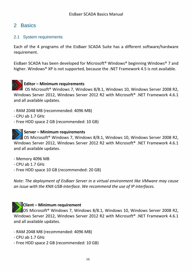
Each of the 4 programs of the EisBaer SCADA Suite has a different software/hardware requirement. EisBaer SCADA has been developed for Microsoft® Windows® beginning Windows® 7 and higher. Windows® XP is not supported, because the .NET Framework 4.5 is not available.
Editor – Minimum requirements OS Microsoft® Windows 7, Windows 8/8.1, Windows 10, Windows Server 2008 R2, Windows Server 2012, Windows Server 2012 R2 with Microsoft® .NET Framework 4.6.1 and all available updates.
‐ RAM 2048 MB (recommended: 4096 MB) ‐ CPU ab 1.7 GHz ‐ Free HDD space 2 GB (recommended: 10 GB)
Server – Minimum requirements OS Microsoft® Windows 7, Windows 8/8.1, Windows 10, Windows Server 2008 R2, Windows Server 2012, Windows Server 2012 R2 with Microsoft® .NET Framework 4.6.1 and all available updates.
‐ Memory 4096 MB ‐ CPU ab 1.7 GHz ‐ Free HDD space 10 GB (recommended: 20 GB) Note: The deployment of EisBaer Server in a virtual environment like VMware may cause an issue with the KNX‐USB‐interface. We recommend the use of IP interfaces.
Client – Minimum requirement OS Microsoft® Windows 7, Windows 8/8.1, Windows 10, Windows Server 2008 R2, Windows Server 2012, Windows Server 2012 R2 with Microsoft® .NET Framework 4.6.1 and all available updates.
‐ RAM 2048 MB (recommended: 4096 MB) ‐ CPU ab 1.7 GHz ‐ Free HDD space 2 GB (recommended: 10 GB)
EisBaer SCADA Basics Manual
[5]
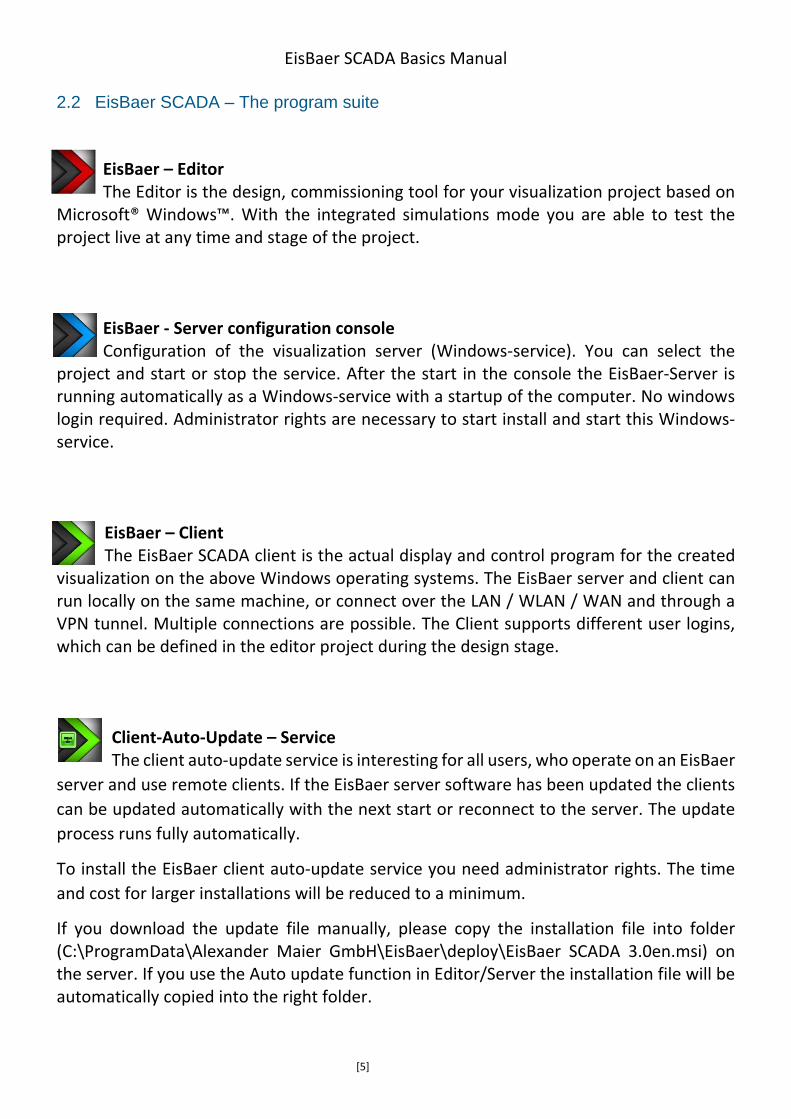
2.2 EisBaer SCADA – The program suite EisBaer – Editor The Editor is the design, commissioning tool for your visualization project based on Microsoft® Windows™. With the integrated simulations mode you are able to test the project live at any time and stage of the project. EisBaer ‐ Server configuration console Configuration of the visualization server (Windows‐service). You can select the project and start or stop the service. After the start in the console the EisBaer‐Server is running automatically as a Windows‐service with a startup of the computer. No windows login required. Administrator rights are necessary to start install and start this Windows‐service.
EisBaer – Client The EisBaer SCADA client is the actual display and control program for the created
visualization on the above Windows operating systems. The EisBaer server and client can run locally on the same machine, or connect over the LAN / WLAN / WAN and through a VPN tunnel. Multiple connections are possible. The Client supports different user logins, which can be defined in the editor project during the design stage.
Client‐Auto‐Update – Service The client auto‐update service is interesting for all users, who operate on an EisBaer
server and use remote clients. If the EisBaer server software has been updated the clients
can be updated automatically with the next start or reconnect to the server. The update
process runs fully automatically.
To install the EisBaer client auto‐update service you need administrator rights. The time
and cost for larger installations will be reduced to a minimum.
If you download the update file manually, please copy the installation file into folder (C:\ProgramData\Alexander Maier GmbH\EisBaer\deploy\EisBaer SCADA 3.0en.msi) on the server. If you use the Auto update function in Editor/Server the installation file will be automatically copied into the right folder.
EisBaer SCADA Basics Manual
[6]
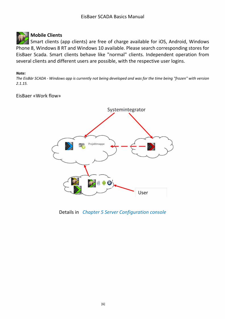
Mobile Clients Smart clients (app clients) are free of charge available for iOS, Android, Windows Phone 8, Windows 8 RT and Windows 10 available. Please search corresponding stores for EisBaer Scada. Smart clients behave like "normal" clients. Independent operation from several clients and different users are possible, with the respective user logins. Note: The EisBär SCADA ‐ Windows app is currently not being developed and was for the time being "frozen" with version 2.1.15.
EisBaer «Work flow»
Details in Chapter 5 Server Configuration console
User
EisBaer SCADA Basics Manual
[7]
3 EisBaer SCADA – Editor
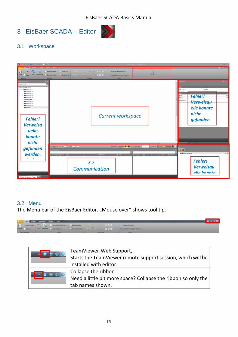
3.1 Workspace
3.2 Menu The Menu bar of the EisBaer Editor. „Mouse over“ shows tool tip.
TeamViewer‐Web Support, Starts the TeamViewer remote support session, which will be installed with editor.
Collapse the ribbonNeed a little bit more space? Collapse the ribbon so only the tab names shown.
0
Fehler! Verweisquelle konnte nicht
gefunden werden. Project
3.7
Communication
Fehler! Verweisquelle konnte
Fehler! Verweisquelle konnte nicht gefunden
Current workspace
EisBaer SCADA Basics Manual
[8]
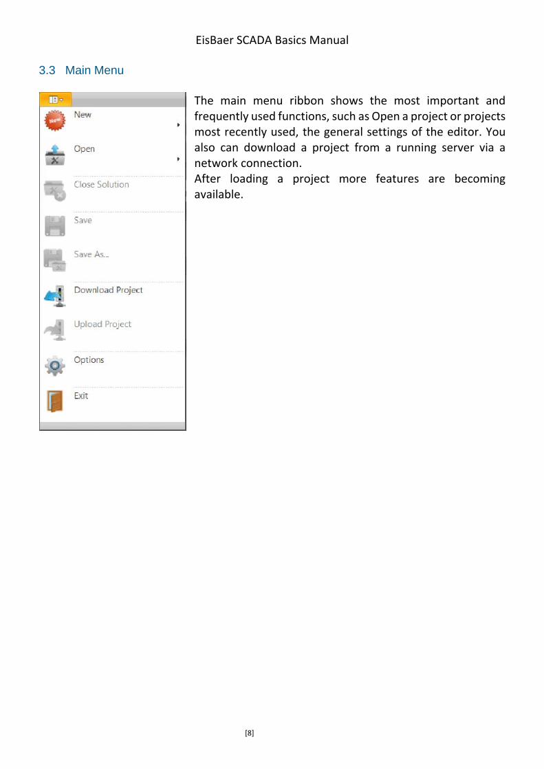
3.3 Main Menu The main menu ribbon shows the most important and frequently used functions, such as Open a project or projects most recently used, the general settings of the editor. You also can download a project from a running server via a network connection. After loading a project more features are becoming available.
EisBaer SCADA Basics Manual
[9]
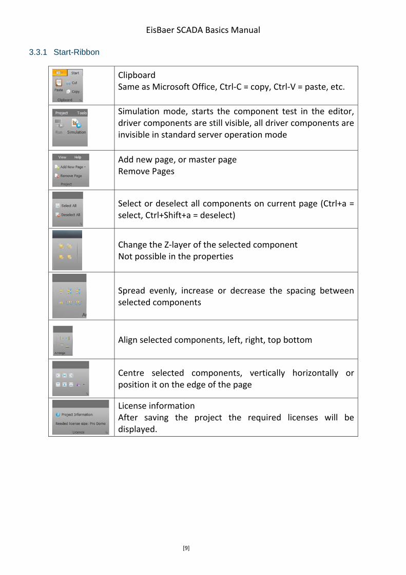
3.3.1 Start-Ribbon
Clipboard Same as Microsoft Office, Ctrl‐C = copy, Ctrl‐V = paste, etc.
Simulation mode, starts the component test in the editor, driver components are still visible, all driver components are invisible in standard server operation mode
Add new page, or master page Remove Pages
Select or deselect all components on current page (Ctrl+a = select, Ctrl+Shift+a = deselect)
Change the Z‐layer of the selected component Not possible in the properties
Spread evenly, increase or decrease the spacing between selected components
Align selected components, left, right, top bottom
Centre selected components, vertically horizontally or position it on the edge of the page
License information After saving the project the required licenses will be displayed.
EisBaer SCADA Basics Manual
[10]
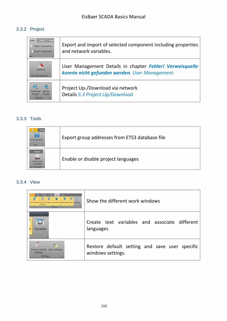
3.3.2 Project
3.3.3 Tools
3.3.4 View
Export and import of selected component including properties and network variables.
User Management Details in chapter Fehler! Verweisquelle konnte nicht gefunden werden. User Management.
Project Up‐/Download via network Details 5.3 Project Up/Download.
Export group addresses from ETS3 database file
Enable or disable project languages
Show the different work windows
Create text variables and associate different languages
Restore default setting and save user specific windows settings.
EisBaer SCADA Basics Manual
[11]
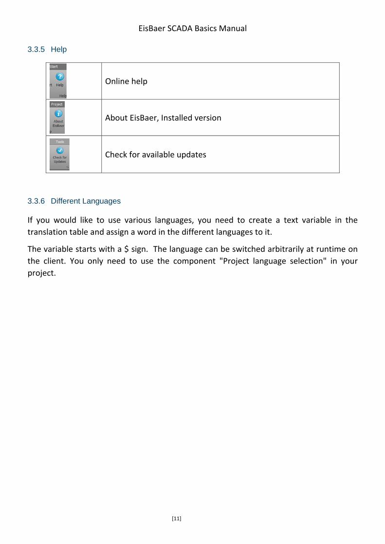
3.3.5 Help
3.3.6 Different Languages
If you would like to use various languages, you need to create a text variable in the
translation table and assign a word in the different languages to it.
The variable starts with a $ sign. The language can be switched arbitrarily at runtime on
the client. You only need to use the component "Project language selection" in your
project.
Online help
About EisBaer, Installed version
Check for available updates
EisBaer SCADA Basics Manual
[12]
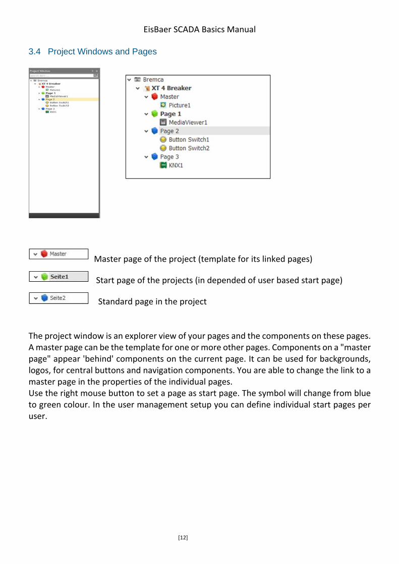
3.4 Project Windows and Pages
Master page of the project (template for its linked pages)
Start page of the projects (in depended of user based start page)
Standard page in the project The project window is an explorer view of your pages and the components on these pages. A master page can be the template for one or more other pages. Components on a "master page" appear 'behind' components on the current page. It can be used for backgrounds, logos, for central buttons and navigation components. You are able to change the link to a master page in the properties of the individual pages. Use the right mouse button to set a page as start page. The symbol will change from blue to green colour. In the user management setup you can define individual start pages per user.
EisBaer SCADA Basics Manual
[13]
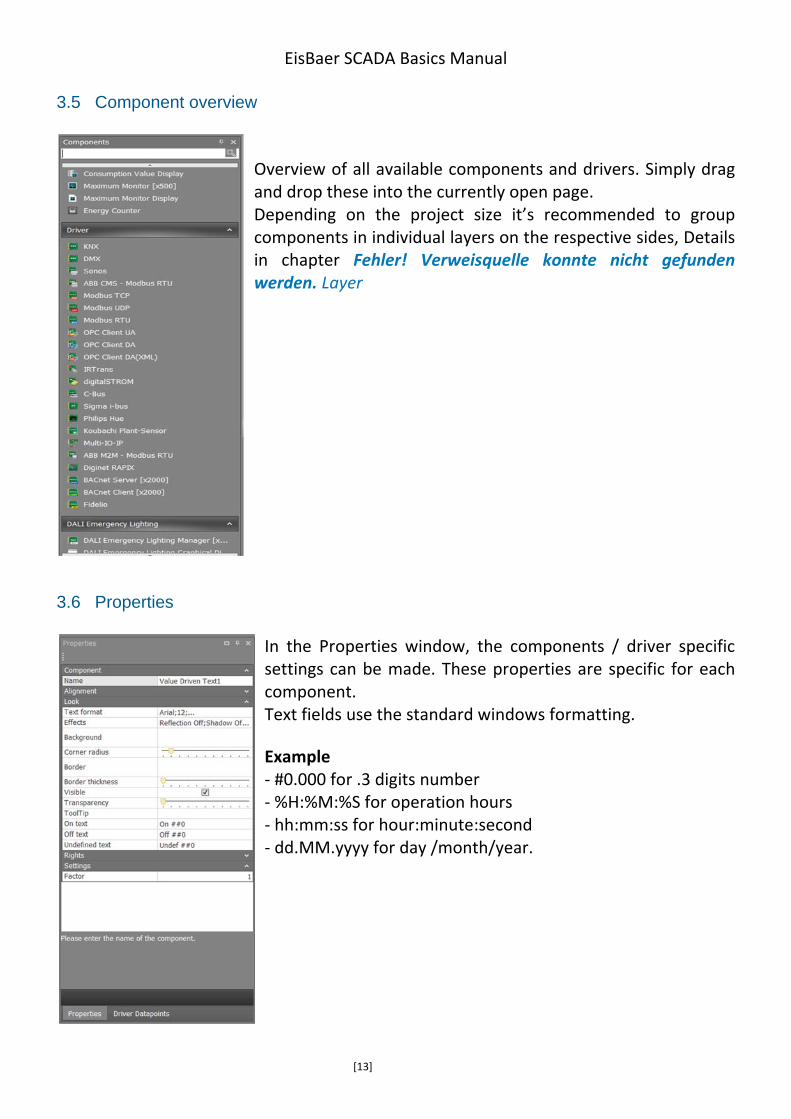
3.5 Component overview Overview of all available components and drivers. Simply drag and drop these into the currently open page. Depending on the project size it’s recommended to group components in individual layers on the respective sides, Details in chapter Fehler! Verweisquelle konnte nicht gefunden werden. Layer
3.6 Properties In the Properties window, the components / driver specific settings can be made. These properties are specific for each component. Text fields use the standard windows formatting.
Example ‐ #0.000 for .3 digits number ‐ %H:%M:%S for operation hours ‐ hh:mm:ss for hour:minute:second ‐ dd.MM.yyyy for day /month/year.
EisBaer SCADA Basics Manual
[14]
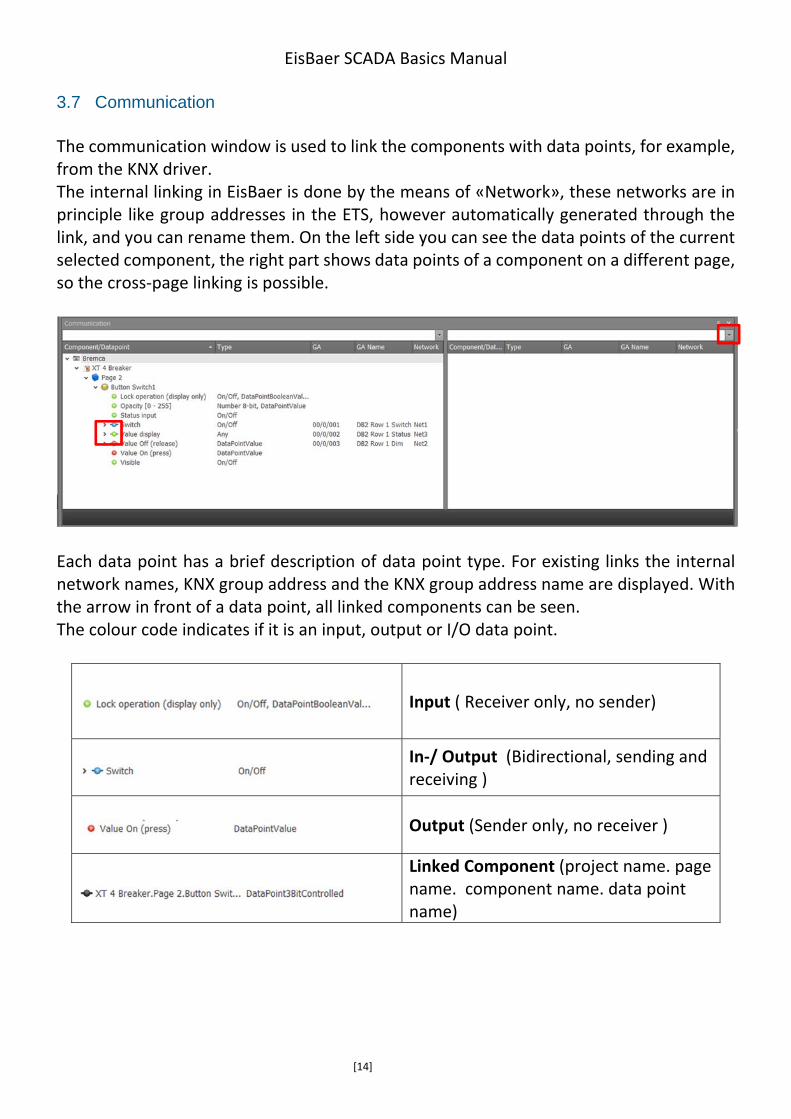
3.7 Communication The communication window is used to link the components with data points, for example, from the KNX driver. The internal linking in EisBaer is done by the means of «Network», these networks are in principle like group addresses in the ETS, however automatically generated through the link, and you can rename them. On the left side you can see the data points of the current selected component, the right part shows data points of a component on a different page, so the cross‐page linking is possible.
Each data point has a brief description of data point type. For existing links the internal network names, KNX group address and the KNX group address name are displayed. With the arrow in front of a data point, all linked components can be seen. The colour code indicates if it is an input, output or I/O data point.
Input ( Receiver only, no sender)
In‐/ Output (Bidirectional, sending and receiving )
Output (Sender only, no receiver )
Linked Component (project name. page name. component name. data point name)
EisBaer SCADA Basics Manual
[15]
3.8 Data point list
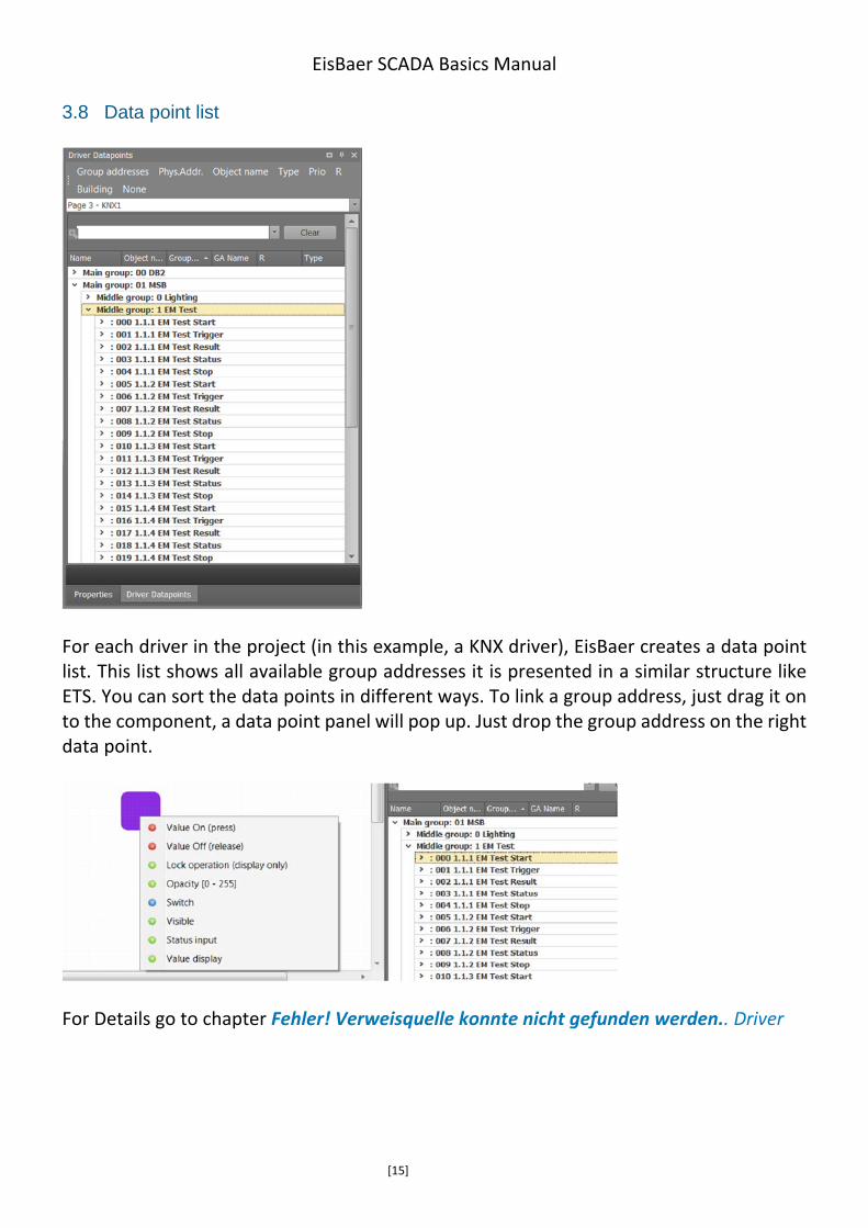
For each driver in the project (in this example, a KNX driver), EisBaer creates a data point list. This list shows all available group addresses it is presented in a similar structure like ETS. You can sort the data points in different ways. To link a group address, just drag it on to the component, a data point panel will pop up. Just drop the group address on the right data point.
For Details go to chapter Fehler! Verweisquelle konnte nicht gefunden werden.. Driver
EisBaer SCADA Basics Manual
[16]
3.9 Layer
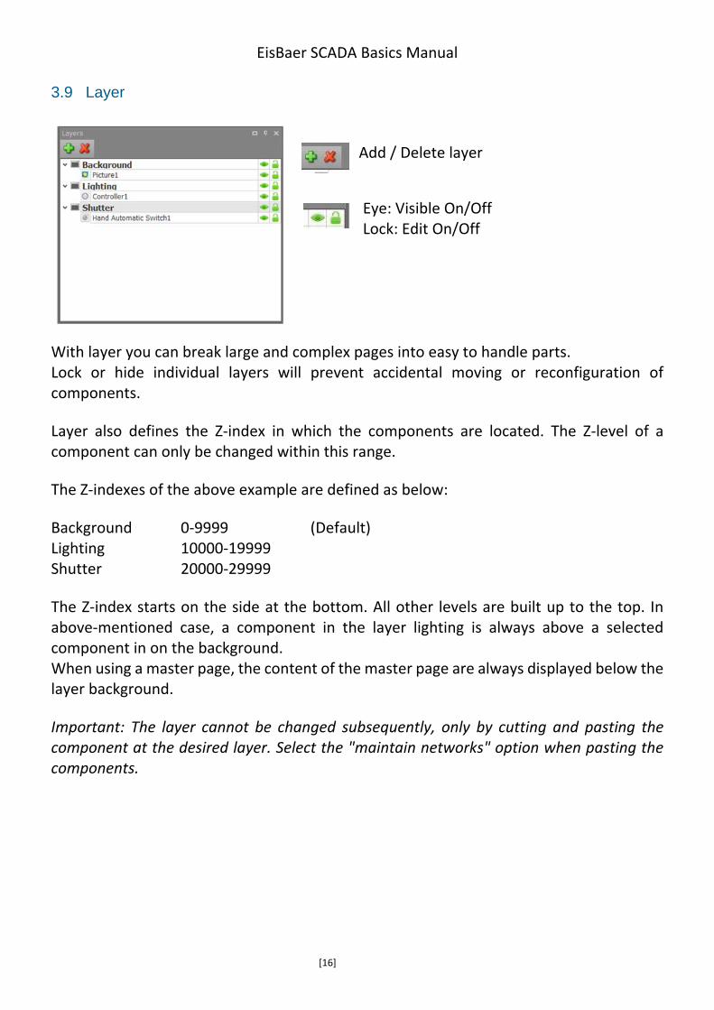
Add / Delete layer
Eye: Visible On/Off Lock: Edit On/Off
With layer you can break large and complex pages into easy to handle parts. Lock or hide individual layers will prevent accidental moving or reconfiguration of components.
Layer also defines the Z‐index in which the components are located. The Z‐level of a component can only be changed within this range.
The Z‐indexes of the above example are defined as below:
Background 0‐9999 (Default) Lighting 10000‐19999 Shutter 20000‐29999
The Z‐index starts on the side at the bottom. All other levels are built up to the top. In above‐mentioned case, a component in the layer lighting is always above a selected component in on the background. When using a master page, the content of the master page are always displayed below the layer background.
Important: The layer cannot be changed subsequently, only by cutting and pasting the component at the desired layer. Select the "maintain networks" option when pasting the components.
EisBaer SCADA Basics Manual
[17]
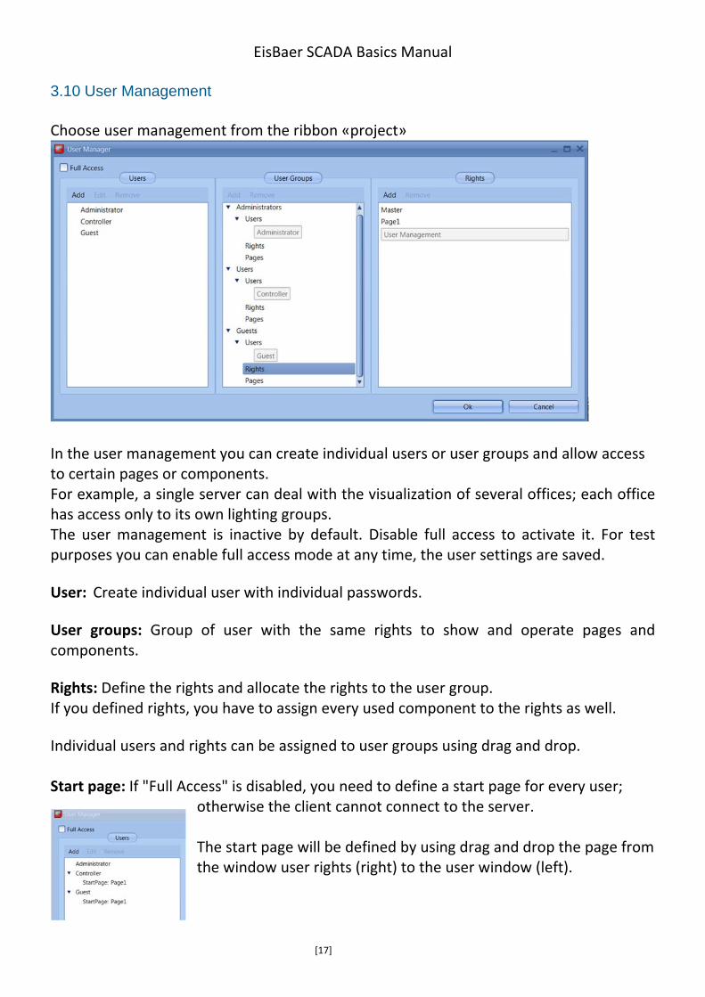
3.10 User Management Choose user management from the ribbon «project»
In the user management you can create individual users or user groups and allow access to certain pages or components. For example, a single server can deal with the visualization of several offices; each office has access only to its own lighting groups. The user management is inactive by default. Disable full access to activate it. For test purposes you can enable full access mode at any time, the user settings are saved.
User: Create individual user with individual passwords.
User groups: Group of user with the same rights to show and operate pages and components.
Rights: Define the rights and allocate the rights to the user group. If you defined rights, you have to assign every used component to the rights as well.
Individual users and rights can be assigned to user groups using drag and drop.
Start page: If "Full Access" is disabled, you need to define a start page for every user; otherwise the client cannot connect to the server. The start page will be defined by using drag and drop the page from the window user rights (right) to the user window (left).
EisBaer SCADA Basics Manual
[18]
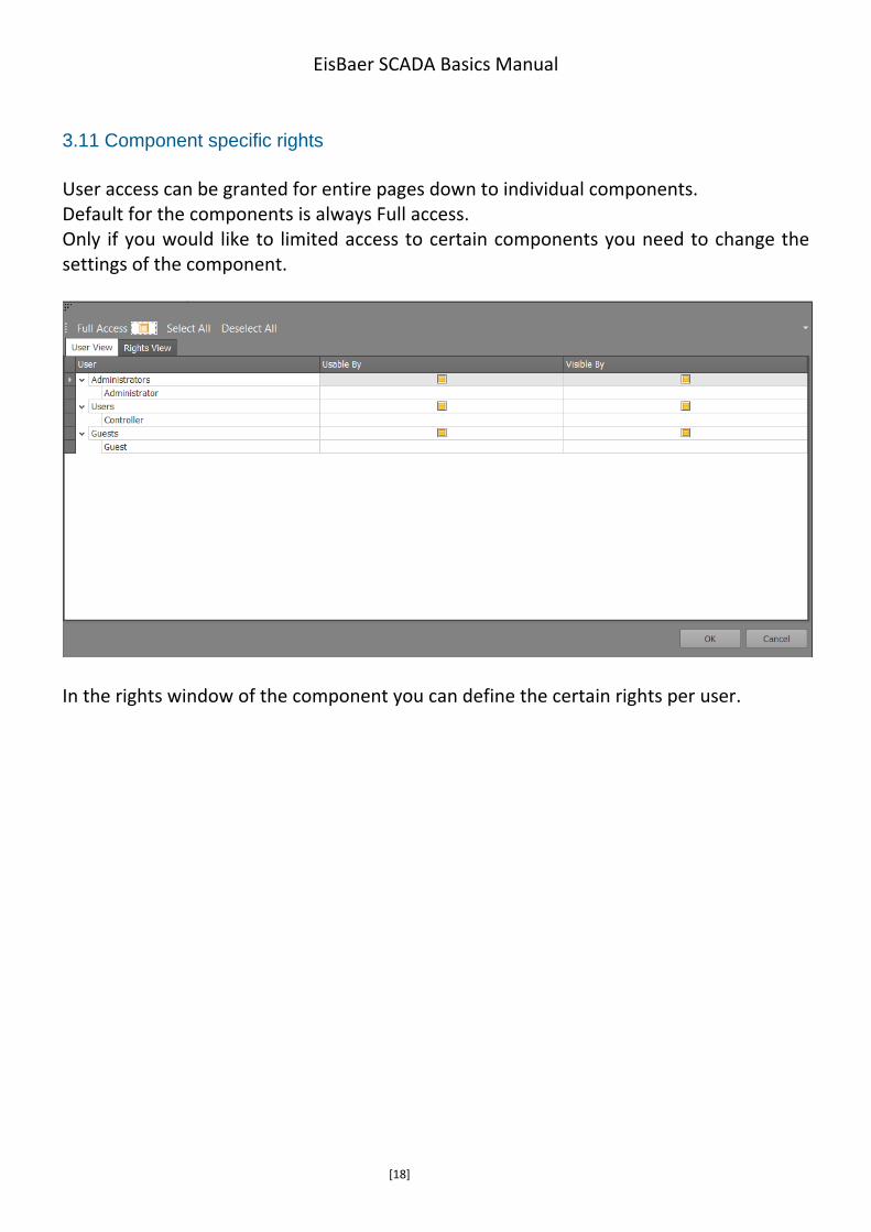
3.11 Component specific rights User access can be granted for entire pages down to individual components. Default for the components is always Full access. Only if you would like to limited access to certain components you need to change the settings of the component.
In the rights window of the component you can define the certain rights per user.
EisBaer SCADA Basics Manual
[19]
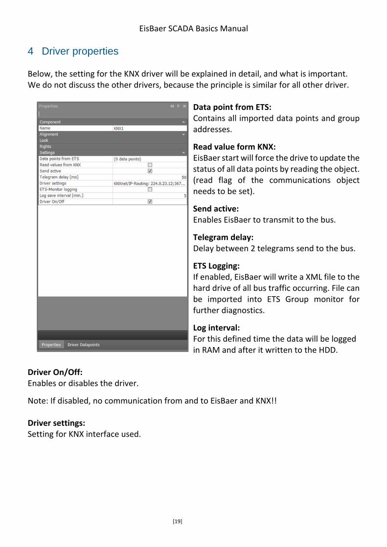
4 Driver properties Below, the setting for the KNX driver will be explained in detail, and what is important. We do not discuss the other drivers, because the principle is similar for all other driver.
Data point from ETS: Contains all imported data points and group addresses.
Read value form KNX: EisBaer start will force the drive to update the status of all data points by reading the object. (read flag of the communications object needs to be set).
Send active: Enables EisBaer to transmit to the bus.
Telegram delay: Delay between 2 telegrams send to the bus.
ETS Logging: If enabled, EisBaer will write a XML file to the hard drive of all bus traffic occurring. File can be imported into ETS Group monitor for further diagnostics.
Log interval: For this defined time the data will be logged in RAM and after it written to the HDD.
Driver On/Off: Enables or disables the driver.
Note: If disabled, no communication from and to EisBaer and KNX!! Driver settings: Setting for KNX interface used.
EisBaer SCADA Basics Manual
[20]
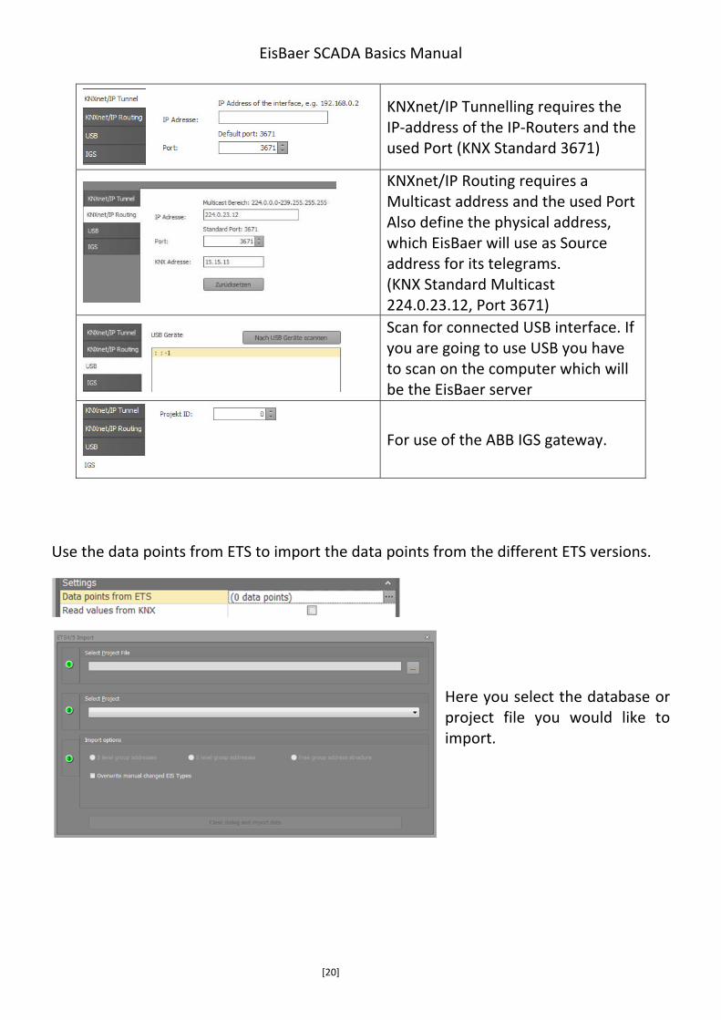
Use the data points from ETS to import the data points from the different ETS versions.
Here you select the database or project file you would like to import.
KNXnet/IP Tunnelling requires the IP‐address of the IP‐Routers and the used Port (KNX Standard 3671)
KNXnet/IP Routing requires a Multicast address and the used Port Also define the physical address, which EisBaer will use as Source address for its telegrams. (KNX Standard Multicast 224.0.23.12, Port 3671)
Scan for connected USB interface. If you are going to use USB you have to scan on the computer which will be the EisBaer server
For use of the ABB IGS gateway.
EisBaer SCADA Basics Manual
[21]
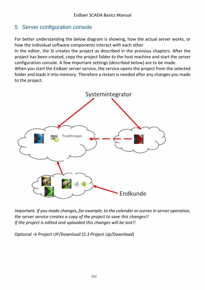
5 Server configuration console For better understanding the below diagram is showing, how the actual server works, or how the individual software components interact with each other In the editor, the SI creates the project as described in the previous chapters. After the project has been created, copy the project folder to the host machine and start the server configuration console. A few important settings (described below) are to be made. When you start the EisBaer server service, the service opens the project from the selected folder and loads it into memory. Therefore a restart is needed after any changes you made to the project.
Important: If you made changes, for example, to the calendar or scenes in server operation, the server service creates a copy of the project to save this changes!! If the project is edited and uploaded this changes will be lost!! Optional → Project UP/Download (5.3 Project Up/Download)
EisBaer SCADA Basics Manual
[22]
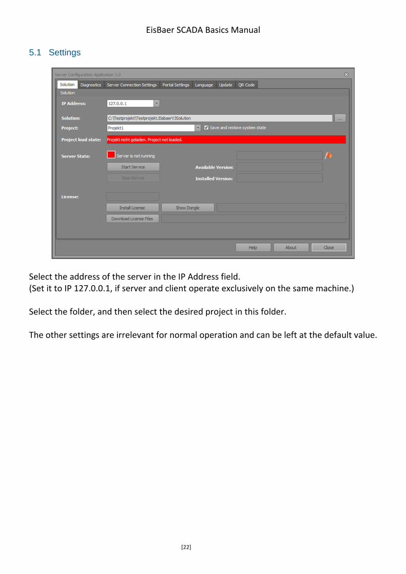
5.1 Settings
Select the address of the server in the IP Address field. (Set it to IP 127.0.0.1, if server and client operate exclusively on the same machine.) Select the folder, and then select the desired project in this folder. The other settings are irrelevant for normal operation and can be left at the default value.
EisBaer SCADA Basics Manual
[23]
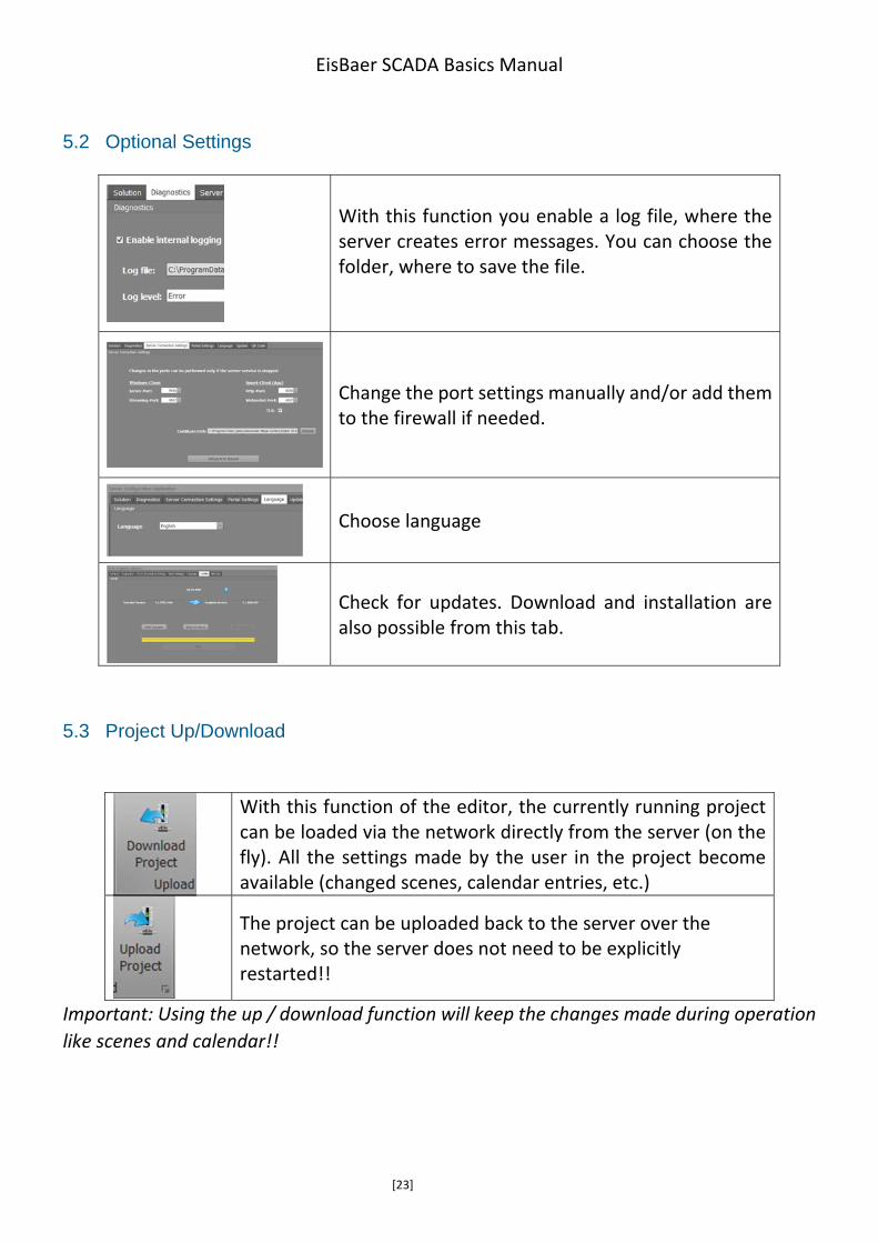
5.2 Optional Settings
5.3 Project Up/Download
Important: Using the up / download function will keep the changes made during operation
like scenes and calendar!!
With this function you enable a log file, where the server creates error messages. You can choose the folder, where to save the file.
Change the port settings manually and/or add them to the firewall if needed.
Choose language
Check for updates. Download and installation are also possible from this tab.
With this function of the editor, the currently running project can be loaded via the network directly from the server (on the fly). All the settings made by the user in the project become available (changed scenes, calendar entries, etc.)
The project can be uploaded back to the server over the network, so the server does not need to be explicitly restarted!!
EisBaer SCADA Basics Manual
[24]
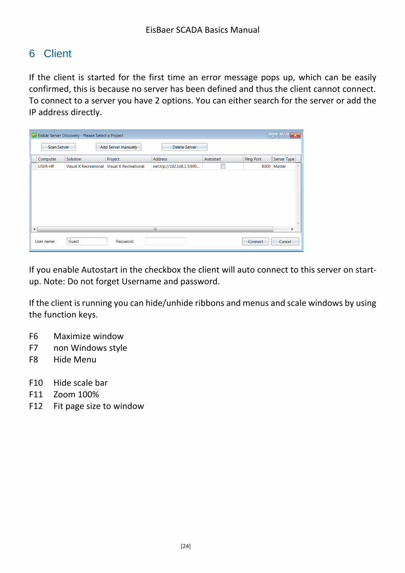
6 Client If the client is started for the first time an error message pops up, which can be easily confirmed, this is because no server has been defined and thus the client cannot connect. To connect to a server you have 2 options. You can either search for the server or add the IP address directly.
If you enable Autostart in the checkbox the client will auto connect to this server on start‐up. Note: Do not forget Username and password.
If the client is running you can hide/unhide ribbons and menus and scale windows by using the function keys.
F6 Maximize window F7 non Windows style F8 Hide Menu F10 Hide scale bar F11 Zoom 100% F12 Fit page size to window
EisBaer SCADA Basics Manual
[25]
7 Create project
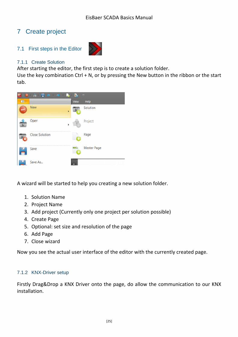
7.1 First steps in the Editor 7.1.1 Create Solution After starting the editor, the first step is to create a solution folder. Use the key combination Ctrl + N, or by pressing the New button in the ribbon or the start tab.
A wizard will be started to help you creating a new solution folder.
1. Solution Name
2. Project Name
3. Add project (Currently only one project per solution possible) 4. Create Page 5. Optional: set size and resolution of the page 6. Add Page 7. Close wizard
Now you see the actual user interface of the editor with the currently created page.
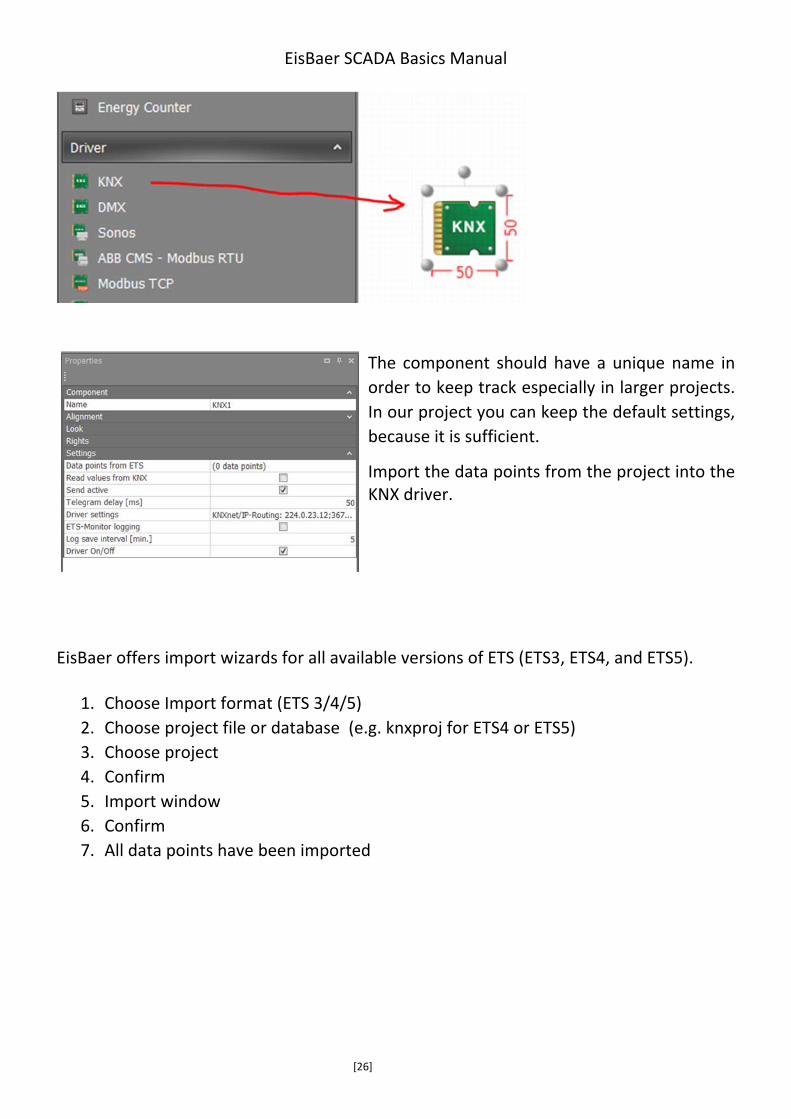
7.1.2 KNX-Driver setup
Firstly Drag&Drop a KNX Driver onto the page, do allow the communication to our KNX installation.
EisBaer SCADA Basics Manual
[26]
The component should have a unique name in
order to keep track especially in larger projects.
In our project you can keep the default settings,
because it is sufficient.
Import the data points from the project into the KNX driver.
EisBaer offers import wizards for all available versions of ETS (ETS3, ETS4, and ETS5).
1. Choose Import format (ETS 3/4/5)
2. Choose project file or database (e.g. knxproj for ETS4 or ETS5) 3. Choose project 4. Confirm
5. Import window
6. Confirm
7. All data points have been imported
EisBaer SCADA Basics Manual
[27]
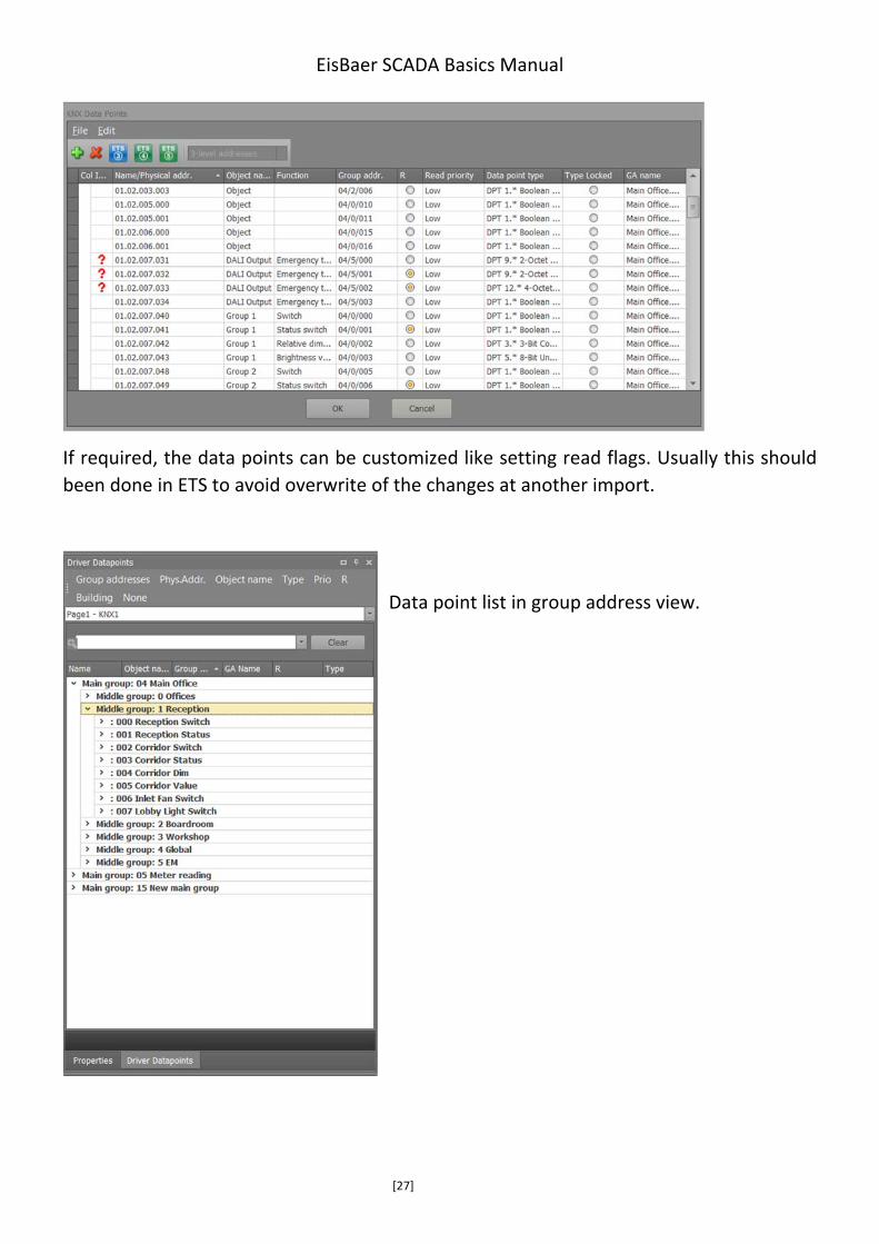
If required, the data points can be customized like setting read flags. Usually this should
been done in ETS to avoid overwrite of the changes at another import.
Data point list in group address view.
EisBaer SCADA Basics Manual
[28]
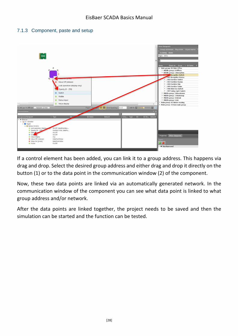
7.1.3 Component, paste and setup
If a control element has been added, you can link it to a group address. This happens via
drag and drop. Select the desired group address and either drag and drop it directly on the
button (1) or to the data point in the communication window (2) of the component.
Now, these two data points are linked via an automatically generated network. In the
communication window of the component you can see what data point is linked to what
group address and/or network.
After the data points are linked together, the project needs to be saved and then the
simulation can be started and the function can be tested.
EisBaer SCADA Basics Manual
[29]
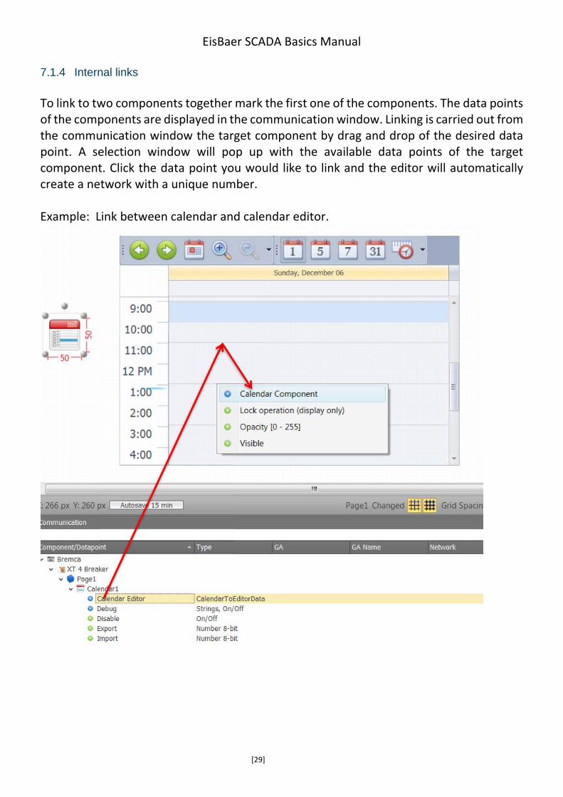
7.1.4 Internal links To link to two components together mark the first one of the components. The data points of the components are displayed in the communication window. Linking is carried out from the communication window the target component by drag and drop of the desired data point. A selection window will pop up with the available data points of the target component. Click the data point you would like to link and the editor will automatically create a network with a unique number. Example: Link between calendar and calendar editor.
EisBaer SCADA Basics Manual
[30]
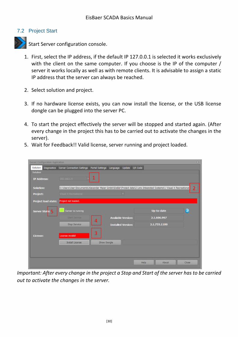
7.2 Project Start
Start Server configuration console.
1. First, select the IP address, if the default IP 127.0.0.1 is selected it works exclusively with the client on the same computer. If you choose is the IP of the computer / server it works locally as well as with remote clients. It is advisable to assign a static IP address that the server can always be reached.
2. Select solution and project.
3. If no hardware license exists, you can now install the license, or the USB license dongle can be plugged into the server PC.
4. To start the project effectively the server will be stopped and started again. (After every change in the project this has to be carried out to activate the changes in the server).
5. Wait for Feedback!! Valid license, server running and project loaded.
Important: After every change in the project a Stop and Start of the server has to be carried
out to activate the changes in the server.
1
2
3
4
5

EisBaer SCADA Basics Manual
[31]
7.3 Client connection
Start Client:
1. First start takes a few minutes, because the client does not know the server yet.
2. Confirm error messages with OK/
3. Click «File» and «Open» to open the search console
4. A: discover server in the network with "Scan Server" After a network scan, all available server show up in the table.
B: with „Add server manually “ you can manually key in the IP address of the server
you would like to connect to
5. Enable Autostart on the server you would like to connect to and with the next start the client will automatically connect to this server.
6. If required set username and password.

Rev. 1a – 13. August 2018
8 Contact
Alexander Maier GmbH Beckstraße 3 D‐69412 Eberbach Tel. +49‐(0)6271‐919470 Fax. +49‐(0)6271‐919479 www.busbaer.de [email protected]
9 Sources: www.busbaer.de www.knx.org