ejx910a and ejx930a multivariable transmitters
TRANSCRIPT

8/9/2019 EJX910A and EJX930A Multivariable Transmitters
http://slidepdf.com/reader/full/ejx910a-and-ejx930a-multivariable-transmitters 1/81
User’sManual
EJX910A and EJX930AMultivariable Transmitters
IM 01C25R01-01E
IM 01C25R01-01E9th Edition

8/9/2019 EJX910A and EJX930A Multivariable Transmitters
http://slidepdf.com/reader/full/ejx910a-and-ejx930a-multivariable-transmitters 2/81
i
IM 01C25R01-01E
EJX910A and EJX930A
Multivariable Transmitters
IM 01C25R01-01E 9th Edition
9th Edition: Mar. 2012 (YK) All Rights Reserved, Copyright © 2005, Yokogawa Electric Corporation
Contents
1. Introduction ............................................................................................... 1-1
Regarding This Manual ................................................................................................1-2
1.1 Safe Use of This Product .................................................................................1-2
1.2 Warranty .............................................................................................................1-3
1.3 ATEX Documentation .......................................................................................1-4
2. About the EJX Multivariable Transmitter ............................................... 2-1
2.1 Features .............................................................................................................2-1
2.2 Initial Check and Installation Procedure ........................................................2-1
2.3 Flow Calculation ...............................................................................................2-3
2.4 Auto Compensation Mode ...............................................................................2-3
2.4.1 Conguration Procedure for Auto Compensation Mode ................... 2-4
2.5 Basic Mode ........................................................................................................2-4
2.5.1 Conguration Procedure for Basic Mode ..........................................2-6
2.5.2 Calculation of the Basic mode parameters ........................................2-6
3. Handling Cautions .................................................................................... 3-1
3.1 Model and Specications Check .....................................................................3-1
3.2 Unpacking ..........................................................................................................3-1
3.3 Storage ...............................................................................................................3-1
3.4 Selecting the Installation Location ................................................................3-2
3.5 Pressure Connection ........................................................................................3-2
3.6 Waterproong of Cable Conduit Connections ..............................................3-2
3.7 Restrictions on Use of Radio Transceivers ...................................................3-2
3.8 Insulation Resistance and Dielectric Strength Test ......................................3-2
3.9 Installation of an Explosion-Protected Instrument .......................................3-3
3.9.1 FM Approval .......................................................................................3-4
3.9.2 CSA Certication ................................................................................3-4
3.9.3 CENELEC ATEX (KEMA) Certication ..............................................3-5
3.9.4 IECEx Certication .............................................................................3-9
3.10 EMC Conformity Standards ...........................................................................3-10
3.11 Pressure Equipment Directive (PED) ...........................................................3-10
3.12 Low Voltage Directive ..................................................................................... 3-11
4. Component Names .................................................................................. 4-1

8/9/2019 EJX910A and EJX930A Multivariable Transmitters
http://slidepdf.com/reader/full/ejx910a-and-ejx930a-multivariable-transmitters 3/81
ii
IM 01C25R01-01E
5. Installation ................................................................................................. 5-1
5.1 Precautions .......................................................................................................5-1
5.2 Mounting ...........................................................................................................5-1
5.3 Changing the Process Connection .................................................................5-2
5.4 Swapping the High/Low-pressure Side Connection .....................................5-3
5.4.1 Rotating Pressure-detector Section 180° .........................................5-35.4.2 Using the Communicator ...................................................................5-3
5.5 Rotating Transmitter Section ...........................................................................5-4
5.6 Changing the Direction of Integral Indicator .................................................5-4
6. Installing Impulse Piping ......................................................................... 6-1
6.1 Impulse Piping Installation Precautions ........................................................6-1
6.1.1 Connecting Impulse Piping to a Transmitter ......................................6-1
6.1.2 Routing the Impulse Piping ................................................................6-2
6.2 Impulse Piping Connection Examples ...........................................................6-4
7. Wiring ......................................................................................................... 7-17.1 Wiring Precautions ...........................................................................................7-1
7.2 Selecting the Wiring Materials .........................................................................7-1
7.3 Types of Output .................................................................................................7-1
7.4 Connection ........................................................................................................7-2
7.4.1 Power Supply Wiring Connection ......................................................7-2
7.4.2 External Indicaror Connection ...........................................................7-2
7.4.3 Communicator Connection ................................................................7-2
7.4.4 Check Meter Connection ...................................................................7-2
7.4.5 External Temperature Connection .....................................................7-2
7.5 Wiring .................................................................................................................7-3
7.5.1 Loop Conguration ............................................................................7-3
7.5.2 Wiring Installation ...............................................................................7-4
7.6 RTD Cable Connection ....................................................................................7-4
7.6.1 Connecting Shielded Cable with Cable Gland(External temperature input code: -1, -2, -3, and -4) ........................7-4
7.6.2 Connecting Shielded Cable for Conduit Use(External temperature input code: -B, -C, and -D) .............................7-7
7.6.3 Removing Shielded Cable with Cable Gland(External temperature input code: -1, -2, -3, and -4) .........................7-8
7.6.4 Removing Shielded Cable for Conduit Use(External temperature input code: -B, -C, -D) ....................................7-8
7.6.5 Cable Connection RTD Terminal Box Side ........................................7-8
7.7 Grounding ..........................................................................................................7-9

8/9/2019 EJX910A and EJX930A Multivariable Transmitters
http://slidepdf.com/reader/full/ejx910a-and-ejx930a-multivariable-transmitters 4/81
iii
IM 01C25R01-01E
8. Operation ................................................................................................... 8-1
8.1 Preparation for Starting Operation .................................................................8-1
8.2 Zero Point Adjustment .....................................................................................8-2
8.2.1 Adjusting Zero Point for Differential Pressure....................................8-2
8.2.2 Adjusting Zero Point for Static Pressure ............................................8-2
8.2.3 Adjusting Zero Point for External Temperature ..................................8-38.3 Starting Operation ............................................................................................8-3
8.4 Shutting Down the Transmitter .......................................................................8-4
8.5 Venting or Draining Transmitter Pressure-detector Section .......................8-4
8.5.1 Draining Condensate .........................................................................8-5
8.5.2 Venting Gas........................................................................................8-5
9. Maintenance .............................................................................................. 9-1
9.1 Overview ............................................................................................................9-1
9.2 Calibration Instruments Selection ..................................................................9-1
9.3 Calibration .........................................................................................................9-1
9.3.1 Pressure and Static Pressure. ...........................................................9-1
9.3.2 External Temperature (RTD) ..............................................................9-2
9.4 Disassembly and Reassembly ........................................................................9-4
9.4.1 Replacing the Integral Indicator .........................................................9-4
9.4.2 Replacing the CPU Board Assembly .................................................9-5
9.4.3 Cleaning and Replacing the Capsule Assembly ...............................9-5
9.4.4 Replacing the Process Connector Gaskets .......................................9-7
9.5 Troubleshooting ................................................................................................9-7
9.5.1 Basic Troubleshooting .......................................................................9-79.5.2 Troubleshooting Flowcharts...............................................................9-8
9.5.3 Alarms and Countermeasures .........................................................9-10
10. General Specications .......................................................................... 10-1
10.1 Standard Specications .................................................................................10-1
10.2 Model and Sufx Codes .................................................................................10-6
10.3 Optional Specications .................................................................................10-9
10.4 Dimensions ....................................................................................................10-13
Revision Information

8/9/2019 EJX910A and EJX930A Multivariable Transmitters
http://slidepdf.com/reader/full/ejx910a-and-ejx930a-multivariable-transmitters 5/81
<1. Introduction> 1-1
IM 01C25R01-01E
1. Introduction
Thank you for purchasing the DPharp EJXmultivariable transmitter.
Your EJX multivariable Transmitter was precisely
calibrated at the factory before shipment. To ensureboth safety and efciency, please read this manualcarefully before you operate the instrument.
NOTE
• This manual mainly describes the hardwarecongurations of EJX multivariabletransmitter.
For information on the software congurationand operation, please refer to IM 01C25R02-01E for the HART communication type
and IM 01C25R03-01E for FOUNDATION FieldbusTM communication type.
To ensure correct use of this instrument,read both the hardware and softwaremanuals thoroughly before use.
• This manual covers the EJX910A andEJX930A multivariable transmitter, whosestyle codes are as described in the followingtable.
Unless otherwise stated, the illustrations in
this manual are of the EJX910A multivariabletransmitter. Users of the EJX930A shouldbear in mind that certain features of theirinstrument will differ from those shown in theillustrations of the EJX910A.
Instruction manuals for EJX Multivariable transmitters are composed of the following three
documents.
EJX910A and EJX930A
Multivariable Transmitter
Instruction Manual
(IM01C25R01-01E)
This manual describes following
hardware configuration.
• Handling caution
• Installation
• Installing impulse piping
• Wiring
• Operation
• Maintenance
• General specifications
EJX910A and EJX930A HART Communication Type
Instruction Manualual (IM01C25R02-01E)
EJX910A and EJX930A Fieldbus Communication Type
Instruction Mannual (IM01C25R03-01E)
These manuals describe HART/FOUDATION Fieldbus
parameter configuration.
FSA120 Flow Configuration Software
Instruction Manual (IM01C25R51-01E)
This manual describes mass flow configuration
and transmitter parameter configuration.
This Instruction manual is in help menu of FSA120.
F0101.ai
Model Style code
EJX910A S2
EJX930A S1
8/9/2019 EJX910A and EJX930A Multivariable Transmitters
http://slidepdf.com/reader/full/ejx910a-and-ejx930a-multivariable-transmitters 6/81
<1. Introduction> 1-2
IM 01C25R01-01E
Regarding This Manual
• This manual should be provided to the enduser.
• The contents of this manual are subject tochange without prior notice.
• All rights reserved. No part of this manual maybe reproduced in any form without Yokogawa’swritten permission.
• Yokogawa makes no warranty of any kind withregard to this manual, including, but not limitedto, implied warranty of merchantability andtness for a particular purpose.
• If any question arises or errors are found, or ifany information is missing from this manual,please inform the nearest Yokogawa salesofce.
• The specications covered by this manual arelimited to those for the standard type under thespecied model number break-down and do notcover custom-made instruments.
• Please note that changes in the specications,construction, or component parts of theinstrument may not immediately be reectedin this manual at the time of change, providedthat postponement of revisions will not causedifculty to the user from a functional orperformance standpoint.
• Yokogawa assumes no responsibilities for thisproduct except as stated in the warranty.
• If the customer or any third party is harmed bythe use of this product, Yokogawa assumesno responsibility for any such harm owing toany defects in the product which were notpredictable, or for any indirect damages.
• The following safety symbols are used in thismanual:
WARNING
Indicates a potentially hazardous situation which,if not avoided, could result in death or seriousinjury.
CAUTION
Indicates a potentially hazardous situation which,if not avoided, may result in minor or moderateinjury. It may also be used to alert against unsafepractices.
IMPORTANT
Indicates that operating the hardware or softwarein this manner may damage it or lead to systemfailure.
NOTE
Draws attention to information essential for
understanding the operation and features.
Direct current
1.1 Safe Use of This Product
For the safety of the operator and to protect theinstrument and the system, please be sure to followthis manual’s safety instructions when handling thisinstrument. If these instructions are not heeded,the protection provided by this instrument may beimpaired. In this case, Yokogawa cannot guaranteethat the instrument can be safely operated. Pleasepay special attention to the following points:
(a) Installation
• This instrument may only be installed by anengineer or technician who has an expertknowledge of this device. Operators are notallowed to carry out installation unless theymeet this condition.
• With high process temperatures, care mustbe taken not to burn yourself by touching theinstrument or its casing.
• Never loosen the process connector nuts whenthe instrument is installed in a process. This canlead to a sudden, explosive release of processuids.

8/9/2019 EJX910A and EJX930A Multivariable Transmitters
http://slidepdf.com/reader/full/ejx910a-and-ejx930a-multivariable-transmitters 7/81
<1. Introduction> 1-3
IM 01C25R01-01E
• When draining condensate from the pressuredetector section, take appropriate precautionsto prevent the inhalation of harmful vapors andthe contact of toxic process uids with the skinor eyes.
• When removing the instrument from ahazardous process, avoid contact with the uidand the interior of the meter.
• All installation shall comply with local installationrequirements and the local electrical code.
(b) Wiring
• The instrument must be installed by anengineer or technician who has an expertknowledge of this instrument. Operators are notpermitted to carry out wiring unless they meetthis condition.
• Before connecting the power cables, pleaseconrm that there is no current owing throughthe cables and that the power supply to theinstrument is switched off.
(c) Operation
• Wait 5 min. after the power is turned off, beforeopening the covers.
(d) Maintenance
• Please carry out only the maintenance
procedures described in this manual. If yourequire further assistance, please contact thenearest Yokogawa ofce.
• Care should be taken to prevent the build up ofdust or other materials on the display glass andthe name plate. To clean these surfaces, use asoft, dry cloth.
(e) Explosion Protected Type Instrument
• Users of explosion proof instruments shouldrefer rst to section 3.9 (Installation of an
Explosion Protected Instrument) of this manual.• The use of this instrument is restricted to those
who have received appropriate training in thedevice.
• Take care not to create sparks when accessingthe instrument or peripheral devices in ahazardous location.
(f) Modication
• Yokogawa will not be liable for malfunctions ordamage resulting from any modication madeto this instrument by the customer.
1.2 Warranty
• The warranty shall cover the period noted onthe quotation presented to the purchaser at thetime of purchase. Problems occurring duringthe warranty period shall basically be repairedfree of charge.
• If any problems are experienced with thisinstrument, the customer should contact theYokogawa representative from which thisinstrument was purchased or the nearestYokogawa ofce.
• If a problem arises with this instrument,please inform us of the nature of the problemand the circumstances under which itdeveloped, including the model specicationand serial number. Any diagrams, data andother information you can include in your
communication will also be helpful.• The party responsible for the cost of xing the
problem shall be determined by Yokogawafollowing an investigation conducted byYokogawa.
• The purchaser shall bear the responsibility forrepair costs, even during the warranty period, ifthe malfunction is due to:
- Improper and/or inadequate maintenance bythe purchaser.
- Malfunction or damage due to a failureto handle, use, or store the instrument inaccordance with the design specications.
- Use of the product in question in a locationnot conforming to the standards specied byYokogawa, or due to improper maintenanceof the installation location.
- Failure or damage due to modication orrepair by any party except Yokogawa or anapproved representative of Yokogawa.
- Malfunction or damage from improper
relocation of the product in question afterdelivery.- Reason of force majeure such as res,
earthquakes, storms/oods, thunder/lightening, or other natural disasters, ordisturbances, riots, warfare, or radioactivecontamination.

8/9/2019 EJX910A and EJX930A Multivariable Transmitters
http://slidepdf.com/reader/full/ejx910a-and-ejx930a-multivariable-transmitters 8/81
<1. Introduction> 1-4
IM 01C25R01-01E
1.3 ATEX Documentation
This is only applicable to the countries in the European Union.
GB
DK
I
E
NL
SF
P
F
D
S
LT
LV
PL
EST
SLO
H
BG
RO
M
CZ
SK
GR

8/9/2019 EJX910A and EJX930A Multivariable Transmitters
http://slidepdf.com/reader/full/ejx910a-and-ejx930a-multivariable-transmitters 9/81
<2. About the EJX Multivariable Transmitter> 2-1
IM 01C25R01-01E
2. About the EJX MultivariableTransmitter
This chapter gives an overview of the functions and
the installation of the EJX Multivariable transmitter.For details on specic procedures, refer to thecorresponding chapter.
2.1 Features
• Multi Sensing Function
The EJX multivariable transmitter has a MultiSensing function that enables a single transmitterto measure differential pressure, static pressure,and external temperature. Mass ow measurement
instruments can calculate and output the owvalue using these three measured variables. TheEJXMVTool mass ow conguration software isused to congure mass ow calculation.
• Simultaneous Analog Output and Pulse
Output (HART protocol type)
The EJX multivariable transmitter has one analogoutput for the output of single measured variables.With digital communications, all of these variablescan be output simultaneously.
In addition to analog output, pulse output isprovided as a standard function of the EJXmultivariable transmitter. It can perform both typesof output simultaneously. Pulse output is used fortotal ow, ow rate, and alarm status.
DP sensor
SP sensor
Sensor Capsule
A/D
ROM
PC: Flow configuration
Electronics module
RTD Temperature InputPressure Input
4 to 20 mA output
for selected PV.
RAM
Differential Pressure
/Static Pressure
/Process Temperature/Calculated Mass Flow
ROM
MPU /Calculate Mass Flow /System control D/A
Digital I/O
Pulseoutput Pulse output
or Status output.
Silicon Resonant
sensor
F0201.ai
Figure 2.1 Block Diagram of EJX Multivariable Transmitter System (HART protocol type)
2.2 Initial Check and Installation
ProcedureFigure 2.2 is a owchart showing the basicsequence for installing and wiring an EJXMultivariable Transmitter.
Refer to the specied chapter for the details of eachprocedure.
Flow conguration can be performed at thefollowing stages:
(1) On the bench, before installation.
(2) In the eld, after installation.
IMPORTANT
Before performing ow conguration in the eld,make sure the installation location meets allsafety requirements.

8/9/2019 EJX910A and EJX930A Multivariable Transmitters
http://slidepdf.com/reader/full/ejx910a-and-ejx930a-multivariable-transmitters 10/81
<2. About the EJX Multivariable Transmitter> 2-2
IM 01C25R01-01E
START
Unpacking and
Confirmation of
Specifications
(see Chapter3)
Review the
Handling Cautions
(see Chapter3)
Hazardous
Location?
Nonincendive
Location
Flow Configure
@Bench
Connect
Power Supply
Connect Personal
Computer
Perform
Configuration
Tasks
(see Chapter2)
Review Installation
Considerations
(see Chapter5)
Mount Transmitter
(see Chapter5)
Perform Field
Calibration Tasks
(see Chapter8)
DONE
Review the Manual
(see Chapter3)
Review the Manual
(see Chapter3)
Make Process
Connections
(see Chapter6)
Wiring
(see Chapter7)
Check for Leaks
Flow Configure
@Field
Perform
ConfigurationTasks
(see Chapter2)
Yes
Yes
Yes
Yes
No
No
No
No
F0202.ai
Figure 2.2 Installation Flowchart

8/9/2019 EJX910A and EJX930A Multivariable Transmitters
http://slidepdf.com/reader/full/ejx910a-and-ejx930a-multivariable-transmitters 11/81
<2. About the EJX Multivariable Transmitter> 2-3
IM 01C25R01-01E
2.3 Flow Calculation
There are two ow calculation modes: autocompensation mode and basic mode.
The FlowNavigator Flow Conguration Software isrequired to congure auto compensation mode.(Please refer to IM 01C25R51-01E for FSA120.)
Sections 2.4 and 2.5 give an overview of the twocalculation functions and explain how to congurethem.
2.4 Auto Compensation Mode
Conguration of the uid physical propertiesand the primary device can be performedfrom an FlowNavigator dialog window. In autocompensation mode, all ow factors for owcalculation are dynamically compensated to anoptimum value with a high level of accuracy. Theow factors that are automatically compensated aredischarge coefcient, diameter of primary device,upstream internal pipe diameter, gas expansionfactor, density, and viscosity.
Based Mass Flow Equation
Qm = ε d2 2∆PρC
(1–β4) 4
C, β, ε, d and ρ are dynamically compensatedow factor.
Qm: Mass Flow C: Discharge coefcient β: Diameter ratio ε: Expansion factor d: Diameter of primary device ∆P: Differential Pressure ρ: Density of uid
Volume Flow Equation Qv = Qm / ρ
Physical propertyDB
Fluid condition
Flow calculation
standard
Primary element
information
Transmitter
coefficient
Flow
calculation
Transmitter
coefficient
DIPPR* (gas/liquid)
Steam Table
Natural Gas
Diff pressure (DP)
Static pressure (SP)
External Temperature(ET)
FlowNavigator EJX910A/EJX930A
Sensor input (DP, SP, Temp )
Output for
selected PV.
DP, SP, ET
Mass flow
Optimization
F0203.ai
*: AIChE, DIPPR (Design Institute for Physical Properties) is
a registered trademark of American Institute of Chemical
Engineers.
Figure 2.3 Auto Compensation Mode Block Diagram

8/9/2019 EJX910A and EJX930A Multivariable Transmitters
http://slidepdf.com/reader/full/ejx910a-and-ejx930a-multivariable-transmitters 12/81
<2. About the EJX Multivariable Transmitter> 2-4
IM 01C25R01-01E
2.4.1 Conguration Procedure for Auto
Compensation Mode
The EJXMVTool is required to congure autocompensation mode. Following shows theprocedures for HART protocol type.
Before starting the conguration procedure, have
on hand all data on the uid and the primarydevices.
(1) Have ready a power supply, a personalcomputer, a HART modem, and the FSA120Flow Conguration Software.
(2) Install the mass ow conguration software onthe personal computer.
(3) Connect the EJX multivariable transmitter to thepower supply.
NOTEConguration can be done when the RTD isnot connected, but alarm number 03 will bedisplayed on the indicator.
(4) Connect the HART modem to the personalcomputer and connect its clips to the supplyterminals on the transmitter.
(5) Perform ow conguration.(6) Execute ow simulation using the HART HHT
or the FSA120 to conrm the congured ow
parameters.When executing the simulation, it is necessaryto connect the RTD or mock resistance (about100Ω) to the transmitter.Input the differential pressure, static pressure,and temperature values and conrm that thedesired ow is obtained.
(7) Remove the HART modem from the transmitter.(8) Turn off the power supply.
NOTE
(1) Refer to the following instruction manuals formore detailed explanation.Setting with the HART HHT:
IM01C25R02-01E.Setting with the Fieldbus conguration tool:
IM01C25R03-01E.Setting with the FSA120 software:
IM01C25R51-01E.(2) For the ow conguration in the eld after
installation, perform only steps 4 to 7.
2.5 Basic Mode
In the case of Basic mode, ow operation anddensity compensation are performed conventionallywith the ow factors manually input.
The ow rate is calculated using the constant owfactor.
Density is compensated as follows according to theselection of gas or liquid.
Gas: Compensation as ideal gas bytemperature and pressure.
Liquid: Compensation by temperature.Select the operational expression according to theuid type and unit category, as shown in Table 2.1.
Table 2.1 Flow Operational Expression for Basic Mode
T0201.ai
Flow unit Category Kfactor FlowFluid
type
Mass Flow
Normal · Standard
Volume Flow
Liquid
Normal · Standard
Volume Flow
Volume Flow
Mass Flow
Volume Flow
Gas
*1 Custom setting Parameter
Kfactor = /4×Nc×C/ 1–β4 ×ε×d2× 2×ρb
Kfactor = /4×Nc×C/ 1–β4 ×ε×d2× 2×ρb /ρnorm
Kfactor = /4×Nc×C/ 1–β4 ×ε×d2× 2/ρb
Kfactor = /4×Nc×C/ 1–β4 ×ε×d2× 2×ρb×1/K
Kfactor = /4×Nc×C/ 1–β4 ×ε×d2× 2×ρb×1/K /ρnorm
Kfactor = /4×Nc×C/ 1–β4 ×ε×d2× 2/(ρb×1/K)
Qm, Qv or Qv_norm
= Kfactor × ∆P×(1+Temp K1×(T–Tb))
Qm or Qv_norm
= Kfactor × ∆P×Tb/T×SP/SPb
Qv = Kfactor × ∆P×T/Tb×SPb/SP
*1
*1
*1

8/9/2019 EJX910A and EJX930A Multivariable Transmitters
http://slidepdf.com/reader/full/ejx910a-and-ejx930a-multivariable-transmitters 13/81
<2. About the EJX Multivariable Transmitter> 2-5
IM 01C25R01-01E
Table 2.2 Symbols
# Symbol Description
1 Qm Mass Flow2 Qv Volume Flow3 Qv_norm Normal·Standard Volume Flow4 Nc Unit convert factor 5 Kfactor Basic ow Calculation factor
6 C Discharge Coefcient7 ε Expansion Factor 8 β Diameter Ratio9 d Diameter of orice10 ∆p Differential Pressure
(Transmitter Setting unit)11 ρb Base Density on Tb, SPb Condition12 ρnorm Density on Normal, Standard condition13 Tb Reference temperature unit: K14 T Temperature unit: K15 SPb Reference static pressure unit: kPa abs16 SP Static Pressure unit: kPa abs
17 Temp K1 The density rate of change pertemperature 1degC of a density basevalue (value which set 100% to 1)For volume ow: set 0.
18 K Compressibility factor
Flow Unit Category
Table 2.3 Mass Flow Unit (HART protocol type)
Unit LCD Communication
grams per second g/s ←grams per minute g/m g/mingrams per hour g/h ←kilograms per second kg/s ←kilograms per minute kg/m kg/minkilograms per hour kg/h ←kilograms per day kg/d ←metric tons per minute t/m t/minmetric tons per hour t/h ←metric tons per day t/d ←pounds per second lb/s ←pounds per minute lb/m lb/minpounds per hour lb/h ←pounds per day lb/d ←short tons per minute STon/m STon/min
short tons per hour STon/h ←short tons per day STon/d ←long tons per hour LTon/h ←long tons per day LTon/d ←
Table 2.4 Normal•Standard Volume Flow Unit(HART protocol type)
Unit LCD Communication
normal cubic meter perhour Nm3/h ←
normal liter per hour NL/h ←
standard cubic feet per
minute
SCFM ←
standard liter per hour SL/h ←standard liter per minute SL/m SL/minstandard liter per second SL/s ←normal cubic meter perday
Nm3/d←
standard cubic feet perday
SCFD ←
standard cubic feet perhour
SCFH←
standard cubic feet persecond
SCFS←
standard cubic meter perday
Sm3/d←
standard cubic meter perhour
Sm3/h←
thousand standard cubicfeet per day
MSCFD←
million standard cubicfeet per day
MMSCFD←
Table 2.5 Volume Flow Unit (HART protocol type)
Unit LCD Communication
cubic feet per minute CFM ←gallons per minute GPM ←
liters per minute L/m L/minimperial gallons perminute
IGal/m Impgal/min
cubic meter per hour M3/h ←gallons per second gal/s ←million gallons per day Mgal/d ←liters per second L/s ←million liters per day ML/d ←cubic feet per second CFS ←cubic feet per day ft3/d ←cubic meters per second M3/s ←cubic meters per day M3/d ←imperial gallons per hour IGal/h Impgal/h
imperial gallons per day IGal/d Impgal/dcubic feet per hour CFH ←cubic meters per minute m3/m m3/minbarrels per second bbl/s ←barrels per minute bbl/m bbl/minbarrels per hour bbl/h ←barrels per day bbl/d ←gallons per hour gal/h ←imperial gallons persecond
IGal/s Impgal/s
liters per hour L/h ←gallons per day gal/d ←

8/9/2019 EJX910A and EJX930A Multivariable Transmitters
http://slidepdf.com/reader/full/ejx910a-and-ejx930a-multivariable-transmitters 14/81
<2. About the EJX Multivariable Transmitter> 2-6
IM 01C25R01-01E
2.5.1 Conguration Procedure for Basic
Mode
Either a communicator or the mass owconguration software is required to carry outconguration in basic mode.
Calculation of the basic mode parameters is
necessary to perform conguration. Followingshows the procedures for HART protocol type.
(1) Have ready a power supply, a personalcomputer, a HART modem and the FSA120EJX-MV Conguration DTM.
(2) Install the ow conguration software on thepersonal computer.This is not necessary if only the HARTcommunicator is used for conguration.
(3) Connect the EJX multivariable transmitter to thepower supply.
NOTE
Even when the RTD is not connected and alarmnumber 03 is displayed on the indicator, settingcan be performed.
(4) Connect the HART communicator or the HARTmodem to the transmitter.
(5) Perform ow conguration.(6) Execute ow simulation with the HART HHT
or the FSA120 software in order to conrm thecongured ow parameters.When the simulation is carried out, it isnecessary to connect the RTD or mockresistance (about 100Ω) to the transmitter.Input the differential pressure, static pressure,and temperature values and then conrm thatthe desired ow has been obtained.
(7) Remove the HART communicator or the HARTmodem from the transmitter.
(8) Turn off the power supply.
NOTE
(1) Refer to the following instruction manuals formore detailed explanation.Setting with the HART HHT:
IM01C25R02-01E.Setting with the Fieldbus conguration tool:
IM01C25R03-01E.Setting with the FSA120: IM01C51R01-01E.
(2) For the ow conguration in the eld afterinstallation, perform only steps 4 to 7.
2.5.2 Calculation of the Basic mode
parameters
There are two methods for the calculation of theBasic mode parameters.
Method 1: Calculating the Kfactor by owparameters
Method 2: Calculating the Kfactor by means of theow condition
Method 1. Calculating the Kfactor by ow
parameters.
(1) Selection of the ow equation Select the desired operational expression
according to the uid type and the ow unitcategory shown in Table 2.1.
(2) Conrming the unit The unit to be used in this calculation is as
follows: Differential pressure: Pa Static Pressure: kPa abs
Temperature: K The dimension of the pressure unit Pa are
M•L-1•S-2
Where M: mass (Kg) L: Length (m) S: Time (second)
(3) Preparation of ow parameters for Kfactorcalculation
Each parameter must be expressed in thefollowing units.d: m,ρb and ρnorm: Kg/m3
C, β, ε and K has no dimensions(4) Calculation of the unit conversion coefcient Nc
The ow rate value does not changeautomatically when a ow unit parameter is setfor the transmitter, and is always output as Kg/s(mass ow). M3/s (volume ow), Nm3/s (Normalvolume ow.)
In order to obtain a value in your designatedunit, it is necessary to set Nc.Nc is a conversion coefcient for the ow andDP unit that is designated to be used.
(5) Selection of the Kfactor equation and calculationSelect the Kfactor expression according to theuid type and the unit category shown in Table2.1.Calculate the Kfactor using the parameters andthe expression.

8/9/2019 EJX910A and EJX930A Multivariable Transmitters
http://slidepdf.com/reader/full/ejx910a-and-ejx930a-multivariable-transmitters 15/81
<2. About the EJX Multivariable Transmitter> 2-7
IM 01C25R01-01E
(6) Downloading ow parameter to a transmitterInput Kfactor, Tb, SPb and TempK 1 to thetransmitter using either a Communication toolor EJXMVTool.Use the unit of “Kg/m3/degC” for TempK1
IMPORTANTIf either the setting of ow unit or differentialpressure unit is changed, Kfactor and Nc mustbe recalculated.
Example 1: Calculation of Nc
(1) When ow unit is changed.Nc= (Kg/s) /(Mass Flow unit in use)
Table 2.6 Example of Calculated Nc by Flow Unit
Flow unit Calculation of Nc Nc
kg/s (kg/s) / (kg/s) = (1kg/1s) / (1kg/1s) 1
kg/h (kg/s) / (kg/h) = (1kg/1s) / (1kg/3600s) 3600
lb/s (kg/s) / (lb/s) = (1kg/1s) / (0.4535924kg/1s) 2.204623
lb/h (kg/s) / (lb/h) = (1kg/1s) / (0.4535924kg/3600s) 7936.648
(2) When differential pressure unit is changed.
Nc = (Differential pressure unit)/(Pa)
Table 2.7 Example of Calculated Nc by Differential Pressure Unit
T0202.ai
∆p unit
inH2O@68degF / Pa = 248.6406Pa / 1Pa
Calculation of Nc
248.6406 = 15.76834
Nc
Pa
kPa
inH2O@68degF
(Pa) / (Pa) = (1Pa) / (1Pa)
kPa/Pa = 1000Pa / 1Pa
1 = 1
1000 = 31.62278
(3) When both ow unit and differential pressure unit are changed.
Nc =(Kg/s)/(Mass Flow unit of use) × (Differential pressure unit of use)/(Pa)
Example 2: Calculation of Kfactor
Qm unit = kg/s, Differential pressure unit = kPaKfactor = /4 × Nc × C/ 1− β4 × ε × d2 × 2×ρb×1/K
= 0.7853982 × 31.62278 × 0.6043 / 1−0.1296 × 0.984 × 0.031622 × 2×1.250380×1/1
= 0.02502868
0.02503

8/9/2019 EJX910A and EJX930A Multivariable Transmitters
http://slidepdf.com/reader/full/ejx910a-and-ejx930a-multivariable-transmitters 16/81
<2. About the EJX Multivariable Transmitter> 2-8
IM 01C25R01-01E
Table 2.8 Flow Parameter of Example
T0203.ai
C
ε
β
d
Dρb
Tb
SPb
K
/4
Nc
Symbol
0.6043
0.984
0.6
0.03162 m
0.0527 m1.250380 kg/m3
273.15 K(0 degC)
101.325 kPa abs
1
0.7853982
31.62278
Value
Discharge coefficient Orifice Corner Taps [ISO5167-1 1991] ReD 1×10⁶
Expansion factor β=0.6, ∆ρ=50,000 Pa, SP=1,000,000 Pa abs, κ=1.399502
Diameter ratio
Bore of orifice
Pipe diameter Base Density on Tb, SPb Condition (NITROGEN 101,325 Pa abs 273.15 K)
Reference temperature unit: K
Reference static pressure unit: kPa abs
Compressibility factor
Unit convert factor when DP unit is kPa kPa/Pa = 1000Pa / 1Pa =31.62278
Description
Example 3: Calculation of Qm
Δp = 50kPa, SP = 500kPa abs, T = 293.15KQm(kg/s) = Kfactor × ∆p × (Tb / T) × (SP / SPb)
= 0.02503 × 50 × (273.15 / 293.15) × (500 / 101.325)
= 0.3795 (kg/s)
Method 2. Calculating the Kfactor by means of the ow condition.
Flow condition; DP, SP, SPb, T, Tb, and TempK1
(1) Selection of the ow equationSelect a desired operational expression
according to the uid type and the ow unitcategory shown in Table 2.1.
(2) Conrming the unitsThe unit to be used in the ow calculation is asfollows.Static Pressure : kPa absTemperature : KRegardless of the actual setting of the unit forthese items in the transmitter, the above unitsare used for calculation.The ow and the differential pressure are
calculated using the unit set to the transmitter.(3) Preparation of parameters for calculation All parameters use the units which are shownat (2).
(4) Calculation of the Kfactor Calculate the Kfactor by using the parameters
prepared at (3) and ow expression selected at(1).
(5) Downloading ow parameter to transmitter.Input Kfactor, Tb, SPb, and TempK1(liquid)to the transmitter by a communication tool orEJXMVTool.
IMPORTANT
If either the setting of ow unit or differentialpressure unit is changed, Kfactor must berecalculated.

8/9/2019 EJX910A and EJX930A Multivariable Transmitters
http://slidepdf.com/reader/full/ejx910a-and-ejx930a-multivariable-transmitters 17/81
<2. About the EJX Multivariable Transmitter> 2-9
IM 01C25R01-01E
Example: Kfactor Calculation
Table 2.9 Flow Condition Example
Symbol Value Description
Qm 3011.76 (lb/h)∆p 201.0935 inH2O@68degF Differential pressureTb 273.15 K Reference temperature unit: K
SPb 101.325 kPa abs Reference static pressure unit: kPa absT 293.15 K Temperature unit: KSP 500 kPa abs Static pressure unit: kPa abs
Kfactor = Qm(lb/h) / ∆p × (Tb / T) × (SP / SPb)
= 3011.76 / 201.0935 × (273.15 / 293.15) × (500 / 101.325)
= 99.0464
Table 2.10 For HART Communicator (Function : Basic Flow Calc)
Symbol HART Parameter name Item Fast key sequences
Kfactor Flow Calc FixedCalcuration xation value of ow 1, 4, 8, 3
SPb Ref SP Reference static pressure 1, 4, 8, 4
Tb Ref Temp Reference pressure 1, 4, 8, 5
TempK1 Temp K1 The rst in temperature correction coefcient for liquidFor volume ow: set 0.
1, 4, 8, 6

8/9/2019 EJX910A and EJX930A Multivariable Transmitters
http://slidepdf.com/reader/full/ejx910a-and-ejx930a-multivariable-transmitters 18/81
<3. Handling Cautions> 3-1
IM 01C25R01-01E
3. Handling Cautions
This chapter provides important information on howto handle the transmitter. Read this carefully beforeusing the transmitter.
EJX Series transmitters are thoroughly tested at thefactory before shipment. When taking delivery of aninstrument, visually check them to make sure thatno damage occurred during shipment.
Also check that all transmitter mounting hardwareshown in gure 3.1 is included. If the transmitteris ordered without the mounting bracket and theprocess connector, the transmitter mountinghardware will not be included. After checking thetransmitter, carefully repack it in its box and keep itthere until you are ready to install it.
Bolt
Process connector
Process connector Gasket
U-bolt nut
U-bolt
Mounting bracket
(L type)
Transmitter mounting bolt
Mounting bracket(Flat type)
Cable gland
F0301.ai
Figure 3.1 Transmitter Mounting Hardware
3.1 Model and Specications
Check
The model name and specications are written onthe name plate attached to the case.
F0302.ai
: Refer to USER'S MANUAL.Made in JapanTOKYO 180-8750 JAPAN
MODEL
SUFFIX
SUPPLY
OUTPUTMWP
mA DC
V DC
STYLE
CAL
RNG
NO.
Figure 3.2 Name Plate
3.2 Unpacking
Keep the transmitter in its original packaging toprevent it from being damaged during shipment.Do not unpack the transmitter until it reaches theinstallation site.
3.3 Storage
The following precautions must be observed whenstoring the instrument, especially for a long period.
(a) Select a storage area which meets the following
conditions:• It is not exposed to rain or subject to waterseepage/leaks.
• Vibration and shock are kept to a minimum.• It has an ambient temperature and relative
humidity within the following ranges.
Ambient temperature: –40* to 85°C without integral indicator
–30* to 80°C with integral indicator * –15°C when /HE is specied.
Relative humidity:0% to 100% R.H.
Preferred temperature and humidity:approx. 25°C and 65% R.H.
(b) When storing the transmitter, repack it carefullyin the packaging that it was originally shippedwith.
(c) If the transmitter has been used, thoroughlyclean the chambers inside the cover anges, sothat there is no process uid remaining inside.Before placing it in storage, also make sure thatthe pressure-detector is securely connected to
the transmitter section.

8/9/2019 EJX910A and EJX930A Multivariable Transmitters
http://slidepdf.com/reader/full/ejx910a-and-ejx930a-multivariable-transmitters 19/81
<3. Handling Cautions> 3-2
IM 01C25R01-01E
3.4 Selecting the Installation
Location
The transmitter is designed to withstand severeenvironmental conditions. However, to ensurethat it will provide years of stable and accurateperformance, take the following precautions when
selecting the installation location.
(a) Ambient Temperature Avoid locations subject to wide temperaturevariations or a signicant temperature gradient.If the location is exposed to radiant heat fromplant equipment, provide adequate thermalinsulation and/or ventilation.
(b) Ambient AtmosphereDo not install the transmitter in a corrosiveatmosphere. If this cannot be avoided, there
must be adequate ventilation as well asmeasures to prevent the leaking of rain waterand the presence of standing water in theconduits.
(c) Shock and Vibration Although the transmitter is designed to berelatively resistant to shock and vibration, aninstallation site should be selected where this iskept to a minimum.
(d) Installation of Explosion-protected Transmitters An explosion-protected transmitters is
certied for installation in a hazardous areacontaining specic gas types. See subsection3.9 “Installation of an Explosion-ProtectedTransmitters.”
3.5 Pressure Connection
WARNING
• Never loosen the process connector boltswhen an instrument is installed in a process.
The device is under pressure, and a loss ofseal can result in a sudden and uncontrolledrelease of process uid.
• When draining toxic process uids that havecondensed inside the pressure detector,take appropriate steps to prevent the contactof such uids with the skin or eyes and theinhalation of vapors from these uids.
The following precautions must be observedin order to safely operate the transmitter underpressure.
(a) Make sure that all the process connector boltsare tightened rmly.
(b) Make sure that there are no leaks in the impulse
piping.(c) Never apply a pressure higher than thespecied maximum working pressure.
3.6 Waterproong of Cable
Conduit Connections
Apply a non-hardening sealant to the threadsto waterproof the transmitter cable conduitconnections. (See gure 7.8, 7.9 and 7.10)
3.7 Restrictions on Use of RadioTransceivers
IMPORTANT
Although the transmitter has been designed toresist high frequency electrical noise, if a radiotransceiver is used near the transmitter or itsexternal wiring, the transmitter may be affectedby high frequency noise pickup. To test this, startout from a distance of several meters and slowly
approach the transmitter with the transceiverwhile observing the measurement loop for noiseeffects. Thereafter use the transceiver outsidethe range where the noise effects were rstobserved.
3.8 Insulation Resistance and
Dielectric Strength Test
Since the transmitter has undergone insulationresistance and dielectric strength tests at the factory
before shipment, normally these tests are notrequired. If the need arises to conduct these tests,heed the following:
(a) Do not perform such tests more frequently thanis absolutely necessary. Even test voltages thatdo not cause visible damage to the insulationmay degrade the insulation and reduce safetymargins.

8/9/2019 EJX910A and EJX930A Multivariable Transmitters
http://slidepdf.com/reader/full/ejx910a-and-ejx930a-multivariable-transmitters 20/81
<3. Handling Cautions> 3-3
IM 01C25R01-01E
(b) Never apply a voltage exceeding 500 V DC(100 V DC with an internal lightning protector)for the insulation resistance test, nor a voltageexceeding 500 V AC (100 V AC with an internallightning protector) for the dielectric strengthtest.
(c) Before conducting these tests, disconnect
all signal lines from the transmitter terminals.The procedure for conducting these tests is asfollows:
• Insulation Resistance Test
1) Short-circuit four terminals of SUPPLY +,SUPPLY –, PULSE + and – in the terminal box.
2) Turn OFF the insulation tester. Then connectthe insulation tester plus (+) lead wire to theshorted SUPPLY terminals and the minus (–)leadwire to the grounding terminal.
3) Turn ON the insulation tester power andmeasure the insulation resistance. The voltageshould be applied as briey as possible to verifythat the insulation resistance is at least 20 MΩ.
4) After completing the test and being very carefulnot to touch exposed conductors disconnect theinsulation tester and connect a 100 kΩ resistorbetween the grounding terminal and the short-circuiting SUPPLY terminals. Leave this resistorconnected at least one second to discharge anystatic potential. Do not touch the terminals whileit is discharging.
• Dielectric Strength Test
1) Short-circuit four terminals of SUPPLY +,SUPPLY –, PULSE + and – in the terminal box.
2) Turn OFF the dielectric strength tester. Thenconnect the tester between the shortedSUPPLY terminals and the grounding terminal.Be sure to connect the grounding lead of thedielectric strength tester to the ground terminal.
3) Set the current limit on the dielectric strengthtester to 10 mA, then turn ON the power and
gradually increase the test voltage from ‘0’ tothe specied voltage.4) When the specied voltage is reached, hold it
for one minute.5) After completing this test, slowly decrease the
voltage to avoid any voltage surges.
3.9 Installation of an Explosion-
Protected Instrument
WARNING
For FOUNDATION Filedbus explosion protedted
type, please refer to IM 01C25R03-01E.
If a customer makes a repair or modication toan intrinsically safe or explosionproof instrumentand the instrument is not restored to its originalcondition, its intrinsically safe or explosionproofconstruction may be compromised and theinstrument may be hazardous to operate. Pleasecontact Yokogawa before making any repair ormodication to an instrument.
CAUTION
This instrument has been tested and certiedas being intrinsically safe or explosionproof.Please note that severe restrictions apply to thisinstrument’s construction, installation, externalwiring, maintenance and repair. A failure to abideby these restrictions could make the instrument ahazard to operate.
WARNING
Maintaining the safety of explosionproofequipment requires great care during mounting,wiring, and piping. Safety requirements alsoplace restrictions on maintenance and repair.Please read the following sections very carefully.
WARNING
The range setting switch must not be used in ahazardous area.
WARNING
Make sure to apply necessary protections on theexternal temperature input cable, so as to avoiddamages leading to an earth fault.

8/9/2019 EJX910A and EJX930A Multivariable Transmitters
http://slidepdf.com/reader/full/ejx910a-and-ejx930a-multivariable-transmitters 21/81
<3. Handling Cautions> 3-4
IM 01C25R01-01E
IMPORTANT
All the blind plugs which accompany the EJXtransmitters upon shipment from the factory arecertied by the applicable agency in combinationwith the EJX series transmitters. The plugs which
are marked with the symbols “◊ Ex” on theirsurfaces are certied only in combination withthe EJX series transmitters.
3.9.1 FM Approval
a. FM Explosionproof Type
Caution for FM explosionproof type.
Note 1. EJX multivariable transmitter with optionalcode /FF1 are applicable for use in
hazardous locations.• Applicable Standard: FM3600, FM3615,FM3810, ANSI/NEMA 250
• Explosionproof for Class I, Division 1,Groups B, C and D.
• Dust-ignitionproof for Class II/III, Division 1,Groups E, F and G.
• Enclosure rating: NEMA 4X.• Temperature Class: T6• Ambient Temperature: –40* to 60°C * –15°C when /HE is specied.
• Supply Voltage: 42 V dc max.
• Output signal: 4 to 20 mA
Note 2. Wiring• All wiring shall comply with National Electrical
Code ANSI/NFPA70 and Local ElectricalCodes.
• When installed in Division 1, “FACTORYSEALED, CONDUIT SEAL NOTREQUIRED.”
Note 3. Operation• Keep the “WARNING” nameplate attached to
the transmitter. WARNING: OPEN CIRCUIT BEFORE
REMOVING COVER. FACTORY SEALED,CONDUIT SEAL NOT REQUIRED.INSTALL IN ACCORDANCE WITH THEUSERS MANUAL IM 01C25.
• Take care not to generate mechanicalsparking when accessing to the instrumentand peripheral devices in a hazardouslocation.
Note 4. Maintenance and Repair • The instrument modication or parts
replacement by other than authorizedrepresentative of Yokogawa ElectricCorporation is prohibited and will voidFactory Mutual Explosionproof Approval.
3.9.2 CSA Certication
a. CSA Explosionproof Type
Caution for CSA explosionproof type.
Note 1. EJX multivariable transmitter with optionalcode /CF1 are applicable for use inhazardous locations:
• Certicate: 2014354• Applicable Standard:
C22.2 No.0, C22.2 No.0.4, C22.2 No.0.5,C22.2 No.25, C22.2 No.30, C22.2 No.94,C22.2 No.61010-1-04, C22.2 No.60079-0,C22.2 No.60079-1
[For CSA C22.2]• Explosion-proof for Class I, Groups B, C and
D.• Dustignition-proof for Class II/III, Groups E, F
and G.• Enclosure: TYPE 4X• Temperature Code: T6...T4[For CSA E60079]• Flameproof for Zone 1, Ex d IIC T6...T4
• Enclosure: IP66 and IP67• Maximum Process Temperature:
120°C (T4), 100°C (T5), 85°C (T6)• Ambient Temperature: –50* to 75°C (T4),
–50* to 80°C (T5), –50* to 75°C (T6) * –15°C when /HE is specied.
• Supply Voltage: 42 V dc max.• Output Signal: 4 to 20 mA dc
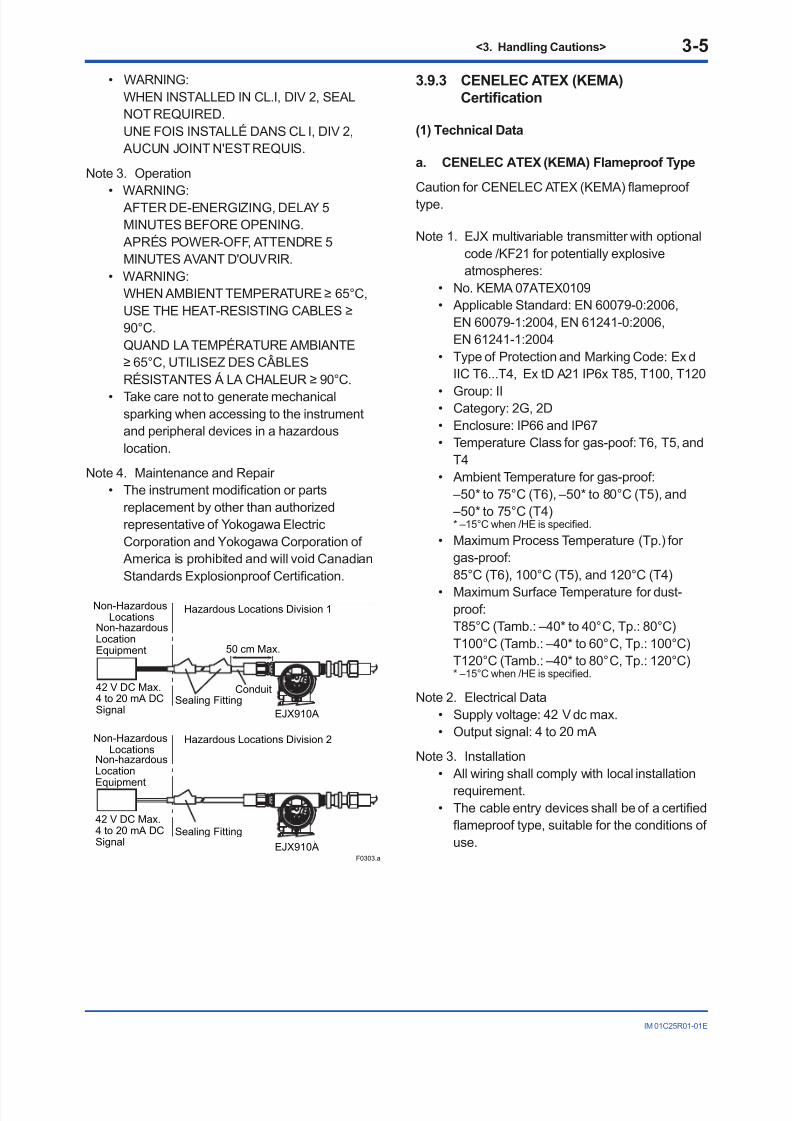
Note 2. Wiring• All wiring shall comply with Canadian
Electrical Code Part I and Local Electrical
Codes.• In hazardous location, wiring shall be inconduit as shown in the gure.
• WARNING: A SEAL SHALL BE INSTALLED WITHIN50cm OF THE ENCLOSURE.
UN SCELLEMENT DOIT ÊTRE INSTALLÉ ÀMOINS DE 50cm DU BOÎTIER.
8/9/2019 EJX910A and EJX930A Multivariable Transmitters
http://slidepdf.com/reader/full/ejx910a-and-ejx930a-multivariable-transmitters 22/81
<3. Handling Cautions> 3-5
IM 01C25R01-01E
• WARNING: WHEN INSTALLED IN CL.I, DIV 2, SEAL
NOT REQUIRED. UNE FOIS INSTALLÉ DANS CL I, DIV 2,
AUCUN JOINT N'EST REQUIS.
Note 3. Operation
• WARNING: AFTER DE-ENERGIZING, DELAY 5MINUTES BEFORE OPENING. APRÉS POWER-OFF, ATTENDRE 5MINUTES AVANT D'OUVRIR.
• WARNING:WHEN AMBIENT TEMPERATURE ≥ 65°C,USE THE HEAT-RESISTING CABLES ≥90°C.
QUAND LA TEMPÉRATURE AMBIANTE≥ 65°C, UTILISEZ DES CÂBLESRÉSISTANTES Á LA CHALEUR ≥ 90°C.
• Take care not to generate mechanicalsparking when accessing to the instrumentand peripheral devices in a hazardouslocation.
Note 4. Maintenance and Repair • The instrument modication or parts
replacement by other than authorizedrepresentative of Yokogawa ElectricCorporation and Yokogawa Corporation of America is prohibited and will void CanadianStandards Explosionproof Certication.
Non-hazardousLocationEquipment
42 V DC Max.4 to 20 mA DCSignal
Non-HazardousLocations
Hazardous Locations Division 1
Non-HazardousLocations
Hazardous Locations Division 2
50 cm Max.
Sealing FittingConduit
Non-hazardousLocation
Equipment
42 V DC Max.4 to 20 mA DCSignal
Sealing Fitting
F0303.ai
S U P P L Y
P U L S
E
C H E C K
A L A R M
S U P P L Y
P U L S E
C H E C K
A L A R M
EJX910A
EJX910A
3.9.3 CENELEC ATEX (KEMA)
Certication
(1) Technical Data
a. CENELEC ATEX (KEMA) Flameproof Type
Caution for CENELEC ATEX (KEMA) ameprooftype.
Note 1. EJX multivariable transmitter with optionalcode /KF21 for potentially explosiveatmospheres:
• No. KEMA 07ATEX0109• Applicable Standard: EN 60079-0:2006,
EN 60079-1:2004, EN 61241-0:2006,EN 61241-1:2004
• Type of Protection and Marking Code: Ex dIIC T6...T4, Ex tD A21 IP6x T85, T100, T120
• Group: II• Category: 2G, 2D• Enclosure: IP66 and IP67• Temperature Class for gas-poof: T6, T5, and
T4• Ambient Temperature for gas-proof:
–50* to 75°C (T6), –50* to 80°C (T5), and –50* to 75°C (T4)
* –15°C when /HE is specied.
• Maximum Process Temperature (Tp.) forgas-proof:
85°C (T6), 100°C (T5), and 120°C (T4)
• Maximum Surface Temperature for dust-proof:T85°C (Tamb.: –40* to 40°C, Tp.: 80°C)T100°C (Tamb.: –40* to 60°C, Tp.: 100°C)T120°C (Tamb.: –40* to 80°C, Tp.: 120°C)
* –15°C when /HE is specied.
Note 2. Electrical Data• Supply voltage: 42 V dc max.• Output signal: 4 to 20 mA
Note 3. Installation• All wiring shall comply with local installation
requirement.• The cable entry devices shall be of a certied
ameproof type, suitable for the conditions ofuse.

8/9/2019 EJX910A and EJX930A Multivariable Transmitters
http://slidepdf.com/reader/full/ejx910a-and-ejx930a-multivariable-transmitters 23/81
<3. Handling Cautions> 3-6
IM 01C25R01-01E
Note 4. Operation• Keep the “WARNING” label attached to the
transmitter. WARNING: AFTER DE-ENERGIZING,
DELAY 5 MINUTES BEFORE OPENING.WHEN THE AMBIENT TEMP.≥65°C,USE HEAT-RESISTING CABLES ≥90°C.
• Take care not to generate mechanicalsparking when accessing to the instrumentand peripheral devices in a hazardouslocation.
Note 5. Maintenance and Repair • The instrument modication or part
replacement by other than an authorizedrepresentative of Yokogawa ElectricCorporation is prohibited and will void KEMAFlameproof Certication.
WARNING
To satisfy IP66 or IP67, apply waterproof glandsto the electrical connection port.
b. CENELEC ATEX (KEMA) Intrinsically Safe
Type
Caution for CENELEC ATEX (KEMA) Intrinsicallysafe type.
Note 1. Model EJX Series Multivariable transmitterwith optional code /KS2 for potentiallyexplosive atmospheres:
• No. KEMA 06ATEX0037 X• Applicable Standard: EN 50014:1997,
EN 50020:2002, EN 50284:1999,EN 50281-1-1:1998
• Type of Protection and Marking code:EEx ia IIC T4
• Group: II• Category: 1G, 1D
• Ambient Temperature for gas-proof: –50* to 60°C
* –15°C when /HE is specied.
• Process Temperature (Tp.): 120°C max.• Maximum Surface Temperature for dust-
proof: T85°C (Tamb.: –40* to 60°C, Tp.: 80°C) T100°C (Tamb.: –40* to 60°C, Tp.: 100°C) T120°C (Tamb.: –40* to 60°C, Tp.: 120°C) * –15°C when /HE is specied.
• Enclosure: IP66 and IP67
Note 2. Electrical Data[Supply/Output circuit (terminals + and -)]
In type of explosion protection intrinsic safetyEEx ia IIC, only for connection to a certiedintrinsically safe circuit with following maximumvalues: Ui = 30 V
Ii = 200 mAPi = 0.9 WCi = 10 nFLi = 0 mH
[Pulse Output circuit (terminals - and pulse)] In type of explosion protection intrinsic safety
EEx ia IIC, only for connection to a certiedintrinsically safe circuit with following maximumvalues: Ui = 30 V
Ii = 200 mA
Pi = 0.9 WCi = 10 nFLi = 0 mH
[External temperature input circuit (connector)] In type of explosion protection intrinsic safety
EEx ia IIC, with following maximum values: Uo = 30 V
Io = 95.4 mAPo= 468 mWCo = 11 nFLo= 3.9 mH
Note 3. Installation• All wiring shall comply with local installationrequirements. (Refer to the installationdiagram)
• When the analog and pulse circuits areconnected to separate barriers, it shall beassured that the voltage difference betweenthese output circuits is not more than 30 V.
• When used in a potentially explosiveatmosphere, Requiring the use of apparatusof equipment category 1D or 2D, certiedcable entry devices shall be used that Are
suitable for the application and correctlyinstalled.
Note 4. Maintenance and Repair • The instrument modication or parts
replacement by other than authorizedrepresentative of Yokogawa ElectricCorporation is prohibited and will void KEMAIntrinsically safe Certication.

8/9/2019 EJX910A and EJX930A Multivariable Transmitters
http://slidepdf.com/reader/full/ejx910a-and-ejx930a-multivariable-transmitters 24/81
<3. Handling Cautions> 3-7
IM 01C25R01-01E
Note 5. Special Conditions for Safe Use• In the case where the enclosure of the
Pressure Transmitter is made of aluminium,if it is mounted in an area where the use ofcategory 1 G apparatus is required, it mustbe installed such, that, even in the event ofrare incidents, ignition sources due to impact
and friction sparks are excluded.
Transmitter
SupplySafety Barrier
Nonhazardous Location
[Installation Diagram]
Hazardous Location
+
–
+
–
F0304.ai
(*1)
Note 1
Sensor out
RTD sensor
Note 2
Without pulse output
With pulse output
Transmitter
Supply
Safety Barrier
Nonhazardous LocationHazardous Location
+
– +
–
+
(*1)
Note 1
Sensor out
RTD sensorNote 2
Safety Barrier
+
–
(*1)
Note 1
Pulse
Note 1: • In any safety barriers used the output current must be
limited by a resistor “R” such that Io=Uz/R. • The safety barrier shall be certied by notify body EU
as ATEX. • When using non isolation barrier, connect (*1) to IS
earthing system.Note 2: • RTD sensor is prepared by the user. • The sensor signal line must withstand a test voltage of
500 V AC.
WARNING
To satisfy IP66 or IP67, apply waterproof glandsto the electrical connection port.
c. CENELEC ATEX (KEMA) Intrinsically Safe
Type/CENELEC ATEX (KEMA) Flameproof
Type/CENELEC ATEX Type n
EJX multivariable transmitters with optional code/KU21 can be selected the type of protectionCENELEC ATEX (KEMA) Intrinsically Safe,
Flameproof or CENELEC ATEX Type n for use inhazardous locations.
Note 1. For the installation of this transmitter,once a particular type of protection isselected, any other type of protectioncannot be used. The installation must be inaccordance with the description about thetype of protection in this user’s manual.
Note 2. In order to avoid confusion, unnecessarymarking is crossed out on the label otherthan the selected type of protection whenthe transmitter is installed.
CENELEC ATEX Type of Protection “n”
• Applicable Standard: EN 60079-15• Referential Standards: IEC60079-0• Type of Protection and Marking Code:
Ex nL IIC T4• Group: II• Category: 3G• Temperature Class: T4• Enclosure: IP66 and IP67• Process Temperature: 120°C max.• Ambient Temperature: –50* to 60°C * –15°C when /HE is specied.
Note 1. Electrical Data[Supply and Pulse circuit]
Ui = 30 VCi = 10 nFLi = 0 mH
[Sensor circuit]Uo =7.4 VIo = 25 mA
Po = 46.3 mWCo = 11 nFLo = 3.9 mH
Note 2. Installation• All wiring shall comply with local installation
requirements. (refer to the installationdiagram)

8/9/2019 EJX910A and EJX930A Multivariable Transmitters
http://slidepdf.com/reader/full/ejx910a-and-ejx930a-multivariable-transmitters 25/81
<3. Handling Cautions> 3-8
IM 01C25R01-01E
Note 3. Maintenance and Repair • The instrument modication or parts
replacement by other than authorizedrepresentative of Yokogawa ElectricCorporation is prohibited and will void Typeof Protection “n”.
Transmitter
Supply[Ex nL]
Nonhazardous Location
[Installation Diagram]
Hazardous Location
+
–
+
–
F0305.ai
Power Supply
[Ex nL]
Power Supply
[Ex nL]
Power Supply
Sensor out
RTD sensorNote 1
Without pulse output
With pulse output
Transmitter
Supply
Nonhazardous LocationHazardous Location
Sensor out
RTD sensorNote 1
Pulse
Note 1: • RTD sensor is prepared by the user. • The sensor signal line must withstand a test voltage of
500Vac.
(2) Electrical Connection
A mark indicating the electrical connection type isstamped near the electrical connection port. Thesemarks are as followed.
F0306.ai
Location of the mark
Screw Size Marking
ISO M20 × 1.5 female
A or W ANSI 1/2 NPT female
M
(3) Installation
WARNING
• All wiring shall comply with local installationrequirements and the local electrical code.
• There is no need for conduit seal in Division1 and Division 2 hazardous locationsbecause this product is sealed at the factory.
(4) Operation
WARNING
• OPEN CIRCUIT BEFORE REMOVINGCOVER. INSTALL IN ACCORDANCE WITHTHIS USER’S MANUAL
• Take care not to generate mechanicalsparking when access to the instrument andperipheral devices in a hazardous location.
(5) Maintenance and Repair
WARNING
The instrument modication or parts replacementby other than an authorized Representative ofYokogawa Electric Corporation is prohibited and
will void the certication.

8/9/2019 EJX910A and EJX930A Multivariable Transmitters
http://slidepdf.com/reader/full/ejx910a-and-ejx930a-multivariable-transmitters 26/81
<3. Handling Cautions> 3-9
IM 01C25R01-01E
(6) Name Plate
F0307.ai
Name plate
Tag plate for flameproof type
Tag plate for intrinsically safe type
Tag plate for type n protection
D
D
AFTER DE-ENERGIZING, DELAY 5 MINUTESBEFORE OPENING.WHEN THE AMBIENT TEMP. ≥ 65°C,USE THE HEAT-RESISTING CABLES ≥ 90°C
No. KEMA 07ATEX0109Ex d IIC T6...T4, Ex tD A21, IP6XEnlcosure : IP66, IP67TEMP. CLASS T6 T5 T4MAX PROCESS TEMP.(Tp.) 85 100 120 °CTamb. -50(-15) to 75 80 75 °CT85°C(Tamb.:40°C, Tp.:80°C),T100°C(Tamb.:60°C, Tp.:100°C),T120°C(Tamb.:80°C, Tp.:120°C) Min.Tamb.:-40(-15)°C(for Dust)
No. KEMA 06ATEX0037 XEEx ia IIC T4IP66 and IP67Tamb. -50(-15) to 60°C MIN Tamb.for DUST -40(-15°C)MAX PROCESS TEMP.(Tp) 120°CT85°C(Tp.:80°C), T100°C(Tp.:100°C), T120°C(Tp.:120°C)Supply/Pulse circuitUi=30 V, Ii=200 mA, Pi=0.9 W, Ci=10 nF, Li=0 mHSensor circuitUo=30 V, Io=95.4 mA, Po=468 mW, Co=11 nF, Lo=3.9 mH
WARNING
Ex nL IIC T4IP66 and IP67Tamb. -50(-15) to 60°CMAX PROCESS TEMP. 120°CSupply Circuit / Pulse Circuit Ui=30V Ci=10nF Li=0Sensor Circuit Uo=7.4V Io=25mA Po=46.3mW Co=11nFLo=3.9mH
: Refer to USER'S MANUAL.Made in JapanTOKYO 180-8750 JAPAN
MODEL
SUFFIX
SUPPLY
OUTPUTMWP
mA DC
V DC
STYLE
CAL
RNG
NO.
MODEL: Specied model code.STYLE: Style code
SUFFIX: Specied sufx code.SUPPLY: Supply voltage.OUTPUT: Output signal.MWP: Maximum working pressure.CAL RNG: Specied calibration range.NO.: Serial number and year of production*1.TOKYO 180-8750 JAPAN:
The manufacturer name and the address*2.
*1: The rst number in the second block of “NO.” columnis the last one number of the production year.
second block
NO. 91K819857 132 7
The year 2011
*2: “180-8750” is a zip code which represents thefollowing address.2-9-32 Nakacho, Musashino-shi, Tokyo Japan
3.9.4 IECEx Certication
a. IECEx Flameproof Type
Caution for IECEx ameproof type.
Note 1. EJX multivariable transmitter with optionalcode /SF2 are applicable for use inhazardous locations:
• No. IECEx CSA 07.0008• Applicable Standard: IEC60079-0:2004,
IEC60079-1:2003• Flameproof for Zone 1, Ex d IIC T6...T4• Enclosure: IP66 and IP67• Maximum Process Temperature:
120°C (T4), 100°C (T5), 85°C (T6)• Ambient Temperature: –50* to 75°C (T4),
–50* to 80°C (T5), –50* to 75°C (T6) * –15°C when /HE is specied.
• Supply Voltage: 42 V dc max.• Output Signal: 4 to 20 mA dc
Note 2. Wiring• In hazardous locations, the cable entry
devices shall be of a certied ameprooftype, suitable for the conditions of use andcorrectly installed.
• Unused apertures shall be closed withsuitable ameproof certied blankingelements.
Note 3. Operation
• WARNING: AFTER DE-ENERGIZING, DELAY 5MINUTES BEFORE OPENING.
• WARNING: WHEN AMBIENT TEMPERATURE ≥ 65°C,
USE THE HEAT-RESISTING CABLES ≥90°C.
• Take care not to generate mechanicalsparking when accessing to the instrumentand peripheral devices in a hazardouslocation.
Note 4. Maintenance and Repair • The instrument modication or parts
replacement by other than authorizedrepresentative of Yokogawa ElectricCorporation is prohibited and will void IECExCertication.

8/9/2019 EJX910A and EJX930A Multivariable Transmitters
http://slidepdf.com/reader/full/ejx910a-and-ejx930a-multivariable-transmitters 27/81
<3. Handling Cautions> 3-10
IM 01C25R01-01E
3.10 EMC Conformity Standards
EN61326-1 Class A, Table 2 (For use in industriallocations)
EN61326-2-3
CAUTION
• This instrument is a Class A product,and it is designed for use in the industrialenvironment. Please use this instrument inthe industrial environment only.
• To meet EMC regulations, Yokogawarecommends that customers run signalwiring through metal conduits or useshielded twisted-pair cabling when installingEJX series transmitters in a plant.
3.11 Pressure Equipment
Directive (PED)
(1) General
• EJX series pressure transmitters arecategorized as piping under the pressureaccessories section of directive 97/23/EC,which corresponds to Article 3, Paragraph 3 ofPED, denoted as Sound Engineering Practice(SEP).
• EJX910A-M, EJX910A-H, EJX930A-M,and EJX930A-H can be used above 200bar and therefore considered as a part of apressure retaining vessel where category III,Module H applies. These models with optioncode /PE3 conform to that category.
(2) Technical Data
• Models without /PE3 Article 3, Paragraph 3 of PED, denoted as
Sound Engineering Practice (SEP).
• Models with /PE3 Module: H Type of Equipmen: Pressure Accessory-Vessel Type of uid: Liquid and Gas Group of uid: 1 and 2
ModelCapsule
codePS*1
(bar)V(L)
PS.V(bar.L)
Category*2
EJX910AL 160 0.01 1.6 Article 3,
Paragraph 3(SEP)M, H 250 0.01 2.5
EJX910Awith code
/PE3M, H 250 0.01 2.5 III
EJX930A M, H 500 0.01 5.0 Article 3,
Paragraph 3(SEP)
EJX930Awith code
/PE3M, H 500 0.01 5.0 III
*1: PS is maximum pressure for vessel itself based onPressure Equipment Directive 97/23/EC.
Refer to General specication for maximum workingpressure of a transmitter.
*2: Referred to Table 1 covered by ANNEX II of EC Directiveon Pressure Equipment Directive 97/23/EC
(3) Operation
CAUTION
• The temperature and pressure of uid shouldbe maintained at levels that are consistentwith normal operating conditions.
• The ambient temperature should bemaintained at a level that is consistent withnormal operating conditions.
• Please take care to prevent water hammerand the like from inducing excessivepressures in pipes and valves. If phenomenaare likely, install a safety valve or takesome other appropriate measure to preventpressure from exceeding PS.
• Take appropriate measures at the device orsystem level to protect transmitters if theyare to be operated near an external heatsource.

8/9/2019 EJX910A and EJX930A Multivariable Transmitters
http://slidepdf.com/reader/full/ejx910a-and-ejx930a-multivariable-transmitters 28/81
<3. Handling Cautions> 3-11
IM 01C25R01-01E
3.12 Low Voltage Directive
Applicable standard: EN61010-1
(1) Pollution Degree 2
“Pollution degree” describes the degree towhich a solid, liquid, or gas which deteriorates
dielectric strength or surface resistivityis adhering. “2” applies to normal indooratmosphere. Normally, only non-conductivepollution occurs. Occasionally, however,temporary conductivity caused by condensationmust be expected.
(2) Installation Category I
“Overvoltage category (Installation category)”describes a number which denes a transientovervoltage condition. It implies the regulation
for impulse withstand voltage. “ I ” applies toelectrical equipment which is supplied from thecircuit when appropriate transient overvoltagecontrol means (interfaces) are provided.

8/9/2019 EJX910A and EJX930A Multivariable Transmitters
http://slidepdf.com/reader/full/ejx910a-and-ejx930a-multivariable-transmitters 29/81
<4. Component Names> 4-1
IM 01C25R01-01E
4. Component Names
HIGH LOW
Slide switch
Burnout direction switch
Write protection switch
Burnout DirectionSwitch Position
BO H L
WR E D
H L H L
Burnout direction switch (BO)
Burnout Direction
F0401.ai
Write ProtectionSwitch Position
H L
E D
H L
E D
Write Protection
Hardware write protection switch (WR)
YES(Write disabled)
NO(Write enabled)
Vertical impulse piping type
Pressure-detector section
Cover flange
Terminal box cover
Horizontal impulse piping type
External indicator conduit connection (Note 1)
RTDconnection
Vent plug
Drain plug
Transmitter section
Integralindicator (Note 1)
Mounting screw
Amplifier Cover
CPU assembly
Zero-adjustmentscrew
Conduitconnection
Processconnector (Note 1)
Processconnection
(Note 2)
Note 1: See subsection 10.2, “Model and Sufx Codes,” for details.Note 2: Applicable for HART communication type. Set the switches as shown in the gure above to set the burn-out direction and write
protection. The Burnout switch is set to the H side for delivery (unless option code /C1 or /C2 is specied in the order), and thehardware write protection switch is set to E side. The setting of the switches can be conrmed via communication. An externalzero adjustment screw can only be enabled by communication. To enabled the screw, set a parameter before activating thehardware write protect function. See each communicaion manual.
Note 3: An external zero point adjustment had been disabled by factory setting.Figure 4.1 Component Names
Table 4.1 Display Symbol
Display Symbol Meaning of Display Symbol
The output signal being zero-adjusted is increasing.
The output signal being zero-adjusted is decreasing.
T0401.aiWrite protect function is enabled.

8/9/2019 EJX910A and EJX930A Multivariable Transmitters
http://slidepdf.com/reader/full/ejx910a-and-ejx930a-multivariable-transmitters 30/81
<5. Installation> 5-1
IM 01C25R01-01E
5. Installation
5.1 Precautions
Before installing the transmitter, read the cautionarynotes in section 3.4, “Selecting the Installation
Location.” For additional information on theambient conditions allowed at the installationlocation, refer to subsection 10.1 “StandardSpecications.”
IMPORTANT
• When welding piping during construction,take care not to allow welding currents toow through the transmitter.
• Do not step on this instrument afterinstallation.
5.2 Mounting
The transmitter is shipped with the processconnection, according to the orderingspecications. To change the orientation of theprocess connections, refer to section 5.3.
With differential pressure transmitters,the distance between the impulse pipingconnection ports is usually 54 mm (gure 5.1).
By changing the orientation of the processconnector, the dimension can be changed to 51mm or 57 mm.
The transmitter can be mounted on a nominal50 mm (2-inch) pipe using the mounting bracketsupplied, as shown in gure 5.2 and 5.3.The transmitter can be mounted on either ahorizontal or a vertical pipe.
When mounting the bracket on the transmitter,tighten the (four) bolts that hold the transmitterwith a torque of approximately 39 N·m 4kgf·m.
57 mm 54 mm 51 mm
F0501.ai
Figure 5.1 Process Connector Impulse PipingConnection Distances for multivariableTransmitters
F0502.ai
Horizontal pipe mounting
Vertical pipe mounting
Transmitter mounting bolt
U-bolt nut
Mounting bracket
U-bolt nut
Mounting bracket
50 mm(2-inch) pipe
50 mm(2-inch) pipe
U-bolt
U-bolt
Transmitter mounting bolt
Figure 5.2 Transmitter Mounting (HorizontalImpulse Piping Type)

8/9/2019 EJX910A and EJX930A Multivariable Transmitters
http://slidepdf.com/reader/full/ejx910a-and-ejx930a-multivariable-transmitters 31/81
<5. Installation> 5-2
IM 01C25R01-01E
Vertical pipe mounting(Process connector upside)
Vertical pipe mounting(Process connector downside)
Transmitter mounting bolt
Transmitter mounting bolt
Mounting bracket
Mounting bracket
U-bolt nut
U-bolt nut
U-bolt
U-bolt
50 mm(2-inch) pipe
50 mm(2-inch) pipe
F0503.ai
Figure 5.3 Transmitter Mounting (Vertical ImpulsePiping Type)
5.3 Changing the Process
Connection
The transmitter is shipped with the processconnection specied at the time of ordering. Tochange the process connection, the drain (vent)plug must be repositioned.
To reposition a drain (vent) plug, use a wrench toslowly and gently unscrew it. Then, remove andremount it on the opposite side. Wrap sealing tapearound the drain (vent) plug threads (*1 in the gurebelow), and apply a lubricant to the threads of thedrain (vent) screw(s) (*2 below). To tighten the drain(vent) plugs, apply a torque of 34 to 39 N·m 3.5 to 4kgf·m. Process connector bolts are to be tighteneduniformly to a torque of 39 to 49 N·m 4 to 5 kgf·m.
F0504.ai
*1
*2Drain/vent plug Note: For a horizontal impulsepiping type, moving theprocess connectors fromthe front side to the
back is not allowed.
Vertical impulse piping type Horizontal impulse piping type
Bolt
Processconnector
gasket
Figure 5.4 Changing Process Connection

8/9/2019 EJX910A and EJX930A Multivariable Transmitters
http://slidepdf.com/reader/full/ejx910a-and-ejx930a-multivariable-transmitters 32/81
<5. Installation> 5-3
IM 01C25R01-01E
5.4 Swapping the High/Low-
pressure Side Connection
5.4.1 Rotating Pressure-detector Section180°
This procedure can be applied only to a transmitter
with a vertical impulse piping type.
The procedure below can be used to turn thepressure detector assembly 180°. Performthis operation in a maintenance shop with thenecessary tools laid out and ready for use, and theninstall the transmitter in the eld after making thechange.
1) Use an Allen wrench (JIS B4648, nominal 2.5mm) to remove the two setscrews at the jointbetween the pressure-detector section andtransmitter section.
2) Leaving the transmitter section in position,rotate the pressure-detector section 180°.
3) Tighten the two setscrews to x the pressure-detector section and transmitter sectiontogether (at a torque of 1.5 N·m).
Reposition the process connector and drain(vent) plugs to the opposite side as described insubsection 4.3.
F0505.ai
Process connector
Setscrew
Before After rotating 180°
Figure 5.5 Before and After Modication
5.4.2 Using the Communicator
With a communicator, you can change whichprocess connection is used as the high-pressureside without mechanically rotating the pressure-detector section 180 as described in subsection5.4.1. To change, call parameter ‘H/L swap’ for
HART Communication and select REVERSE (rightside: low pressure; left side: high pressure) or selectNORMAL to change back to normal (right side: highpressure; left side: low pressure).
Output
Input
NORMAL
REVERSE
F0506.ai
Figure 5.6 Input/Output Relationship
IMPORTANT
Since the H/L label plate on the capsuleassembly will remain unchanged, use thisfunction only when you cannot switch theimpulse piping. If the ‘H/L SWAP’ parametersetting is changed, the input/output relationshipis reversed as shown in gure 5.6; be sure this isunderstood by all.

8/9/2019 EJX910A and EJX930A Multivariable Transmitters
http://slidepdf.com/reader/full/ejx910a-and-ejx930a-multivariable-transmitters 33/81
<5. Installation> 5-4
IM 01C25R01-01E
5.5 Rotating Transmitter Section
The transmitter section can be rotatedapproximately 360° (180° to either direction or360° to one direction from the original position atshipment, depending on the conguration of theinstrument.) It can be xed at any angle within
above range.1) Remove the two setscrews that fasten the
transmitter section and capsule assembly,using the Allen wrench.
2) Rotate the transmitter section slowly and stop itat designated position.
3) Tighten the two setscrews to a torque of 1.5N·m.
IMPORTANT
Do not rotate the transmitter section more thanthe above limit.
Vertical impulse piping type
Horizontal impulse piping type
Pressure-detector section
Transmitter section
Rotate 0 to ±180° segments
Rotate 0 to ±180° segmentsTransmitter section
Pressure-detector section
Conduit connection
Conduit connection
Zero-adjustment screw
Stopper
F0507.ai
Figure 5.7 Rotating Transmitter Section (Left SideHigh Pressure Type)
5.6 Changing the Direction of
Integral Indicator
IMPORTANT
Always turn OFF power, release pressure andremove a transmitter to non-hazardous areabefore disassembling and reassmbling anindicator.
An integral indicator can be installed in the followingthree directions. Follow the instructions in section9.4 for removing and attaching the integral indicator.
F0508.ai
Figure 5.8 Integral Indicator Direction

8/9/2019 EJX910A and EJX930A Multivariable Transmitters
http://slidepdf.com/reader/full/ejx910a-and-ejx930a-multivariable-transmitters 34/81
<6. Installing Impulse Piping> 6-1
IM 01C25R01-01E
6. Installing Impulse Piping
6.1 Impulse Piping Installation
Precautions
The impulse piping that connects the processoutputs to the transmitter must convey the processpressure accurately. If, for example, gas collectsin a liquid-lled impulse line, or the drain for agas-lled impulse line becomes plugged, it willnot convey the pressure accurately. Since this willcause errors in the measurement output, selectthe proper piping method for the process uid(gas, liquid, or steam). Pay careful attention to thefollowing points when routing the impulse pipingand connecting the impulse piping to a transmitter.
6.1.1 Connecting Impulse Piping to aTransmitter
(1) Check the High and Low Pressure
Connections on the Transmitter (Figure 6.1)
Symbols “H” and “L” have been placed on thecapsule assembly to indicate high and low pressureside. With differential pressure transmitters, connectthe high pressure side impulse line to the “H” side,and the low pressure side impulse line to the “L”side.
With gauge/absolute pressure transmitters, connectthe impulse line to the ‘H’ side.
F0601.ai
Process
connection
“H” and “L” are shown
Process connection
Process connector
Bolt
Differential Pressure Transmitter
Figure 6.1 “H” and “L” Symbols on a CapsuleAssembly
(2) Changing the Process Connector Piping
Connections (Figure 5.1)
The impulse piping connection distances can bechanged between 51 mm, 54 mm and 57 mm bychanging the orientation of the process connectors.This is convenient for aligning an impulse line with aprocess connectors.
(3) Tightening the Process Connector
Mounting Bolts
After connecting an impulse line, tighten the
process connector mounting bolts uniformly.
(4) Removing the Impulse Piping Connecting
Port Dustproof Cap
The impulse piping connecting port on thetransmitter is covered with a plastic cap to keep outdust. This cap must be removed before connectingthe line. (Be careful not to damage the threadswhen removing this cap. Never insert a screwdriveror other tool between the cap and port threads toremove the cap.)
(5) Connecting the Transmitter and 3-Valve
Manifold
A 3-valve manifold consists of two stop valves toblock process pressure and an equalizing valveto equalize the pressures on the high and lowpressure sides of the transmitter. Such a manifoldmakes it easier to disconnect the transmitterfrom the impulse piping, and is convenient whenadjusting the transmitter zero point.
There are two 3-valve manifold types: the pipe-
mounting type and the direct-mounting type; careshould be taken with respect to the following pointswhen connecting the manifold to the transmitter.
Pipe-Mounting Type 3-Valve Manifold(Figure 6.2)
1) Screw nipples into the connection ports on thetransmitter side of the 3-valve manifold, andinto the impulse piping connecting ports onthe process connectors. (To maintain propersealing, wind sealing tape around the nipple
threads.)2) Mount the 3-valve manifold on the 50 mm (2-inch) pipe by fastening a U-bolt to its mountingbracket. Tighten the U-bolt nuts only lightly atthis time.
3) Install the pipe assemblies between the 3-valvemanifold and the process connectors and lightlytighten the ball head lock nuts. (The ball-shapedends of the pipes must be handled carefully,since they will not seal properly if the ballsurface is scratched or otherwise damaged.)

8/9/2019 EJX910A and EJX930A Multivariable Transmitters
http://slidepdf.com/reader/full/ejx910a-and-ejx930a-multivariable-transmitters 35/81
<6. Installing Impulse Piping> 6-2
IM 01C25R01-01E
4) Now tighten the nuts and bolts securely in thefollowing sequence:
Process connector bolts → transmitter-end ballhead lock nuts → 3-valve manifold ball headlock nuts → 3-valve manifold mounting bracketU-bolt nuts
F0602.ai
Nipple
Nipple
Process
connector
Ball headlock nut
Pipe
Ball headlock nut
Process
connector bolts
50 mm(2-inch) pipe
Pipes
3-valvemanifold
Impulse piping
Vent plug(optional)
Stop valve(low pressure side)
Equalizing valve(balancing)
Stop valve(high pressure side)
Figure 6.2 3-Valve Manifold (Pipe-Mounting Type)
Direct-Mounting Type 3-Valve Manifold(Figure 6.3)
1) Mount the 3-valve manifold on the transmitter. (When mounting, use the two gaskets and the
four bolts provided with the 3-valve manifold.Tighten the bolts evenly.)
2) Mount the process connectors and gasketson the top of the 3-valve manifold (the side onwhich the impulse piping will be connected).
F0603.ai
Bolts
Processconnector
Gasket
Gasket
Processconnector
Bolts
Stop valve
Stop valve
3-valvemanifold
3-valvemanifold
Equalizing valve
Equalizingvalve
Stop valve
Impulsepiping
Impulsepiping
Stop valve
Figure 6.3 3-Valve Manifold (Direct-MountingType)
NOTE
After completing the connection of the transmitterand 3-valve manifold, be sure to CLOSE the lowpressure and high pressure stop valves, OPENthe equalizing valve, and leave the manifold with
the equalizing valve OPEN.You must do this in order to avoid overloadingthe transmitter from either the high or the lowpressure side when beginning operation.This instruction must also be followed as part ofthe startup procedure (chapter 8.)
6.1.2 Routing the Impulse Piping
(1) Process Pressure Tap Angles
If condensate, gas, sediment or other extraneous
material in the process piping gets into the impulsepiping, pressure measurement errors may result. Toprevent such problems, the process pressure tapsmust be angled as shown in gure 6.4 according tothe kind of uid being measured.
NOTE
• If the process uid is a gas, the taps must bevertical or within 45° either side of vertical.
• If the process uid is a liquid, the taps mustbe horizontal or below horizontal, but not
more than 45° below horizontal.• If the process uid is steam or other
condensing vapor, the taps must behorizontal or above horizontal, but not morethan 45° above horizontal.
[Gas]
Pressuretaps
Processpiping
[Steam][Liquid]
45°
45°
45° 45°
45°
45°
F0604.ai
Figure 6.4 Process Pressure Tap Angle (ForHorizontal Piping)

8/9/2019 EJX910A and EJX930A Multivariable Transmitters
http://slidepdf.com/reader/full/ejx910a-and-ejx930a-multivariable-transmitters 36/81
<6. Installing Impulse Piping> 6-3
IM 01C25R01-01E
(2) Position of Process Pressure Taps and
Transmitter
If condensate (or gas) accumulates in the impulsepiping, it should be removed periodically byopening the drain (or vent) plugs. However, this willgenerate a transient disturbance in the pressure
measurement, and therefore it is necessary toposition the taps and route the impulse piping sothat any extraneous liquid or gas generated in theleadlines returns naturally to the process piping.
• If the process uid is a gas, then as a rule thetransmitter must be located higher than theprocess pressure taps.
• If the process uid is a liquid or steam, then as arule the transmitter must be located lower thanthe process pressure taps.
(3) Impulse Piping Slope
The impulse piping must be routed with only anupward or downward slope. Even for horizontalrouting, the impulse piping should have a slope ofat least 1/10 to prevent condensate (or gases) fromaccumulating in the pipes.
(4) Temperature Difference Between Impulse
Lines
If there is a temperature difference between thehigh and low impulse lines, the density difference
of the uids in the two lines will cause an error inthe measurement pressure. When measuring ow,impulse lines must be routed together so that thereis no temperature difference between them.
(5) Condensate Pots for Steam Flow
Measurement
If the liquid in the impulse piping repeatedlycondenses or vaporizes as a result of changesin the ambient or process temperature, this willcause a difference in the uid head between the
high pressure and low pressure sides. To preventmeasurement errors due to these head differences,condensate pots are used when measuring steamow.
(6) Preventing Wind Speed Effects in Very Low
Differential Pressure Measurement
IMPORTANT
When using a differential pressure transmitterto measure very low pressures (draft pressure),
the low pressure connection port is left opento atmospheric pressure (the referencepressure). Any wind around the differentialpressure transmitter will therefore cause errorsin the measurement. To prevent this, it will benecessary either to enclose the transmitter ina box, or to connect an impulse line to the lowpressure side and insert its end into a wind-excluding pot (cylindrical with a base plate).
(7) Preventing Freezing
If there is any risk that the process uid in theimpulse piping or transmitter could freeze, use asteam jacket or heater to maintain the temperatureof the uid.
NOTE
After completing the connections, close thevalves on the process pressure taps (mainvalves), the valves at the transmitter (stopvalves), and the impulse piping drain valves,
so that condensate, sediment, dust and otherextraneous material cannot enter the impulsepiping.

8/9/2019 EJX910A and EJX930A Multivariable Transmitters
http://slidepdf.com/reader/full/ejx910a-and-ejx930a-multivariable-transmitters 37/81
<6. Installing Impulse Piping> 6-4
IM 01C25R01-01E
6.2 Impulse Piping Connection
Examples
Figure 6.5 shows examples of typical impulsepiping connections. Before connecting thetransmitter to the process, study the transmitterinstallation location, the process piping layout,
and the characteristics of the process uid(corrosiveness, toxicity, ammability, etc.), in orderto make appropriate changes and additions to theconnection congurations.
Note the following points when referring to thesepiping examples.
• The high pressure connecting port on thetransmitter is shown on the right (as viewedfrom the front).
• The transmitter impulse piping connection is
shown for a vertical impulse piping connectionconguration in which the direction ofconnection is either upwards or downwards.
• If the impulse line is long, bracing or supportsshould be provided to prevent vibration.
• The impulse piping material used mustbe compatible with the process pressure,temperature, and other conditions.
• A variety of process pressure tap valves (mainvalves) are available according to the typeof connection (anged, screwed, welded),construction (globe, gate, or ball valve),
temperature and pressure. Select the type ofvalve most appropriate for the application.
F0605.ai
Tee
3-valvemanifold
Drainvalve
Orifice
Drainplug
Tapvalve
Unionor flange
Liguid Gas
Condensate pot
Steam
Figure 6.5 Impulse Piping Connection Example

8/9/2019 EJX910A and EJX930A Multivariable Transmitters
http://slidepdf.com/reader/full/ejx910a-and-ejx930a-multivariable-transmitters 38/81
<7. Wiring> 7-1
IM 01C25R01-01E
7. Wiring
7.1 Wiring Precautions
IMPORTANT
• The information in the sections from 7.2throught 7.5 (except for 7.5.2) is specic toHART protocol type. Refer to IM01C25R03-01E for FOUNDATION Fieldbus protocoltype.
• Lay wiring as far as possible from electricalnoise sources such as large capacitytransformers, motors, and power supplies.
• Remove the electrical connection dust capbefore wiring.
• All threaded parts must be treated withwaterproong sealant. (A non-hardeningsilicone group sealant is recommended.)
• To prevent noise pickup, do not pass signaland power cables through the same ducts.
• Explosion-protected instruments mustbe wired in accordance with specicrequirements (and, in certain countries,legal regulations) in order to preserve theeffectiveness of their explosion-protectedfeatures.
• The terminal box cover is locked by an Allen head bolt (a shrouding bolt) on ATEXameproof type transmitters. When theshrouding bolt is driven clockwise usingan Allen wrench, it goes in. The cover lockcan then be released and the cover canbe opened by hand. See subsection 8.4“Disassembly and Reassembly” for details.
• Plug and seal an unused conduit connection.• Do not turn on power until all wirings
including RTD nished.
7.2 Selecting the Wiring
Materials
(a) Use stranded leadwires or cables which arethe same as or better than 600 V grade PVCinsulated wire or its equivalent.
(b) Use shielded wires in areas that are susceptibleto electrical noise.
(c) In areas with higher or lower ambienttemperatures, use appropriate wires or cables.
(d) In environment where oils, solvents, corrosivegases or liquids may be present, use wires orcables that are resistant to such substances.
(e) It is recommended that crimp-on solderlessterminal lugs (for 4 mm screws) with insulating
sleeves be used for leadwire ends.
7.3 Types of Output
Table 7.2 shows the wiring example according tothe output types.
(1) Analog Output (4 to 20 mA DC)
This instruments uses the same two wires for both,the signal and power supply. A DC power supply isrequired in a transmission loop. The total leadwire
resistance including the instrument load and powerdistributor (supplied by the user) must conform toa value in the permissible load resistance range.Refer to Figure below.
F0701.ai
E-10.5
0.0244
(Ω)
Power supply voltage E (V DC)
600
250
R
10.5 16.6 25.2 42
Externalloadresistance
DigitalCommunication
range
R=
Figure 7.1 Relation between Power SupplyVoltage and Load Resistance (4 to 20mA DC Output)

8/9/2019 EJX910A and EJX930A Multivariable Transmitters
http://slidepdf.com/reader/full/ejx910a-and-ejx930a-multivariable-transmitters 39/81
<7. Wiring> 7-2
IM 01C25R01-01E
(2) Pulse output and Alarm, Status Output
This instruments uses three wires between theconverter and the power supply.
A DC power and load resistance are required, andpulse output is connected to a totalizer or an electriccounter.
Low level of the pulse output is 0 to 2V. Nocommunication is possible over a transmission line.
(3) Simultaneous Analog-Pulse Output
When using the simultaneous analog-pulseoutput mode, the communicable distance of thetransmission line is restricted on the wiring method.
Table 7.2 shows the examples of connection for thisoutput mode.
IMPORTANTFor pulse output and the simultaneous analog-pulse output, use the load resistance. Refer toTable 7.2.
7.4 Connection
7.4.1 Power Supply Wiring Connection
Table 7.2 shows the wiring example according to
the output types.
7.4.2 External Indicaror Connection
Connect wiring for external indicators to the CHECK+ and – terminals.
(Note) Use a external indicator whose internal resistance is 10Ωor less.
Transmitter terminal box
External indicator
F0702.ai
Power supply
–
+
S U P P L Y
P U L S E
C H E C K
A L A R M
Figure 7.2 External Indicator Connection
7.4.3 Communicator Connection
Connect the HART Hand Held Terminal (HHT) tothe SUPPLY + and – terminals.
S U P P L Y
P U L S E
C H E C K
A L A R M
Transmitter terminal box
HART HHTF0703.ai
Power supply
–
+
Ignore the polaritysince the HART HHTis AC-coupled to theterminal box.
Figure 7.3 HART HHT Connection
7.4.4 Check Meter Connection
Connect the check meter to the CHECK + and – terminals. (Use hooks.)
• A 4 to 20 mA DC output signal from the CHECK
+ and – terminals.(Note) Use a check meter whose internal resistance is 10 or less.
S U P P L Y
P U L S E
C H E C K
A L A R M
Transmitter terminal box
F0704.ai
Power supply
–
+
Check meter
Figure 7.4 Check Meter Connection
7.4.5 External Temperature Connection
Connect the RTD cable assembly to the JuckTerminal.
F0705.ai
S U P P L Y
P U L S E
C H E C K
A L A R M
Figure 7.5 External temperature Connection

8/9/2019 EJX910A and EJX930A Multivariable Transmitters
http://slidepdf.com/reader/full/ejx910a-and-ejx930a-multivariable-transmitters 40/81
<7. Wiring> 7-3
IM 01C25R01-01E
7.5 Wiring
7.5.1 Loop Conguration
(1) General-use Type and Flameproof Type
• Analog Output
S U P P L Y
P U L S E
C H E C K
A L A R M
Hazardous Location Nonhazardous LocationTransmitter terminal box
Distributor(Power supply unit)
Receiverinstrument
F0706.ai
• Pulse output and Alarm, Status Output or
Simultaneous Analog-Pulse Output
S U P P L Y
P U L S E
C H E C K
A L A R M
Hazardous Location Nonhazardous LocationTransmitter terminal box
Distributor(Power supply unit)
Receiverinstrument
F0707.ai
Receiverinstrument
Figure 7.6 Connection between Transmitter andDistributor
(2) Intrinsically Safe Type
With the intrinsically safe type, a safety barriermust be included in the loop. Followings are wiringexamples.
• Analog Output
S U P P L Y
P U L S E
C H E C K
A L A R M
Hazardous Location Nonhazardous Location
Transmitter terminal box Receiver instrument(and power supply)Safety barreir
(Isolation type)
F0708.ai
Anaolg input
Power supply
• Simultaneous Analog-Pulse Output
S U P P L Y
P U L S E
C H E C K
A L A R M
Hazardous Location Nonhazardous Location
Transmitter terminal boxSafety barrier
(Isolated type)
I/O module
F0709.ai
Safety barrier
(Isolated type)
Powersupply
Powersupply
Analog input
Pulse input
Figure 7.7 Connection between Transmitter,barrier and receiver

8/9/2019 EJX910A and EJX930A Multivariable Transmitters
http://slidepdf.com/reader/full/ejx910a-and-ejx930a-multivariable-transmitters 41/81
<7. Wiring> 7-4
IM 01C25R01-01E
7.5.2 Wiring Installation
(1) General-use Type and Intrinsically Safe
Type
With the cable wiring, use a metallic conduit orwaterproof glands.
• Apply a non-hardening sealant to the terminalbox connection port and to the threads on theexible metal conduit for waterproong.
F0710.ai
Flexible metal conduit
Wiring metalconduit
Tee
Drain plug
Apply a non-hardeningsealant to the threadsfor waterproofing.
Figure 7.8 Typical Wiring Using Flexible MetalConduit
(2) Flameproof Type
Wire cables through a ameproof packing adapter,or use a ameproof metal conduit.
Wiring cable through ameproof packing adapter.
• Apply a non-hardening sealant to the terminalbox connection port and to the threads on theameproof packing adapter for waterproong.
Flameproof packing adapter
Flexible metal conduit
Wiring metalconduit
Tee
Drain plug
Apply a non-hardeningsealant to the threadsfor waterproofing.
F0711.ai
Figure 7.9 Typical Cable Wiring Using FlameproofPacking Adapter
Flameproof metal conduit wiring• A seal tting must be installed near the terminal
box connection port for a sealed construction.• Apply a non-hardening sealant to the threads of
the terminal box connection port, exible metalconduit and seal tting for waterproong.
F0712.ai
Non-hazardous area
Hazardous area
Flameproof heavy-gaugesteel conduit
Tee
Drain plug
Seal fitting
Gas sealing device
Flameproof flexiblemetal conduit
Apply a non-hardeningsealant to the threadsof these fittings for waterproofing
After wiring, impregnate the fittingwith a compound to seal tubing.
Figure 7.10 Typical Wiring Using Flameproof MetalConduit
7.6 RTD Cable Connection
Connection of the RTD cable is always requiredto measure external temperature. Follow theprocedures below to connect and disconnect acable when a cable gland or a conduit is used.
7.6.1 Connecting Shielded Cable withCable Gland(External temperature input code:
-1, -2, -3, and -4)
• RTD connection components: EJX multivariabletransmitter, two cable glands, and RTD cableTwo cable glands are attached.
Y L P P U S
E S L U
P
K C E H C M R A L A
Transmitter
Cable gland
Electrical connection
RTD cablewith connector
Detail of connector
F0713.ai

8/9/2019 EJX910A and EJX930A Multivariable Transmitters
http://slidepdf.com/reader/full/ejx910a-and-ejx930a-multivariable-transmitters 42/81
<7. Wiring> 7-5
IM 01C25R01-01E
• Magnied view of the RTD connector in thetransmitter's terminal box.
S U P P L Y
P U L S E
C H E C K
A L A R M
S U P P L Y
P U L S E
C H E C K
A L A R M
Protection Cap Connecting Port
F0714.ai
The RTD cable connecting port is covered witha cap to keep out dust. The cap should not beremoved until you are ready to install the cable.
CAUTION
Input/output signal is non-isolated.Do not turn on power supply until you completeall the wiring work.
In the case of electrical connection code 2
(1/2NPT female) or 4 (M20 female).
• Components for the cable glandThe cable gland assembly consists of an entry,seal, running coupler, and backnut. Conrm thatthe seal is attached inside the entry and that thethread size of the cable gland is the same as
that for the RTD electrical connection.
F0715.ai
1/2NPT Type
M20 Type
Gasket
Entry with SealRunningCoupler Backnut
Entry with SealRunningCoupler Backnut
Procedure
(1) Disassemble the cable gland: loosen therunning coupler to separate the backnut fromthe entry.
(2) Remove the protection cap over the transmitterelectrical connection and install the entry on the
electrical connection. Note that a non-hardeningsealant should be applied to the threads for a1/2 NPT connection and a gasket should beused for an M20 connection.
Y L P P U S
E S
L U
P
K C E H C M R A L A
F0716.ai
(3) Pass the RTD cable through the runningcoupler and backnut assembly.
F0717.ai
(4) Insert the RTD cable and rmly plug itsconnector into the connecting port in thetransmitter's terminal box.
Y L P P U S
E S L U P
K C E H C M R A L A
F0718.ai
(5) Align the running coupler on the entry.
Y L P P U S
E S L U P
K C E H C M R A L A
F0719.ai

8/9/2019 EJX910A and EJX930A Multivariable Transmitters
http://slidepdf.com/reader/full/ejx910a-and-ejx930a-multivariable-transmitters 43/81
<7. Wiring> 7-6
IM 01C25R01-01E
(6) Turn the running coupler until the seal in theentry comes into contact with the RTD cable.
Y L P P U S
E S L U P
K C E H C M R A L A
F0720.ai
(7) Rotate the running coupler another half turn tosecurely tighten the seal on the RTD cable.
(8) Use a protection conduit, if necessary.In this case, insert the cable through theconduit and attach it to the Backnut.
CAUTION
After the cable is secured as explained above,do not tighten the running coupler any further; todo so could damage the RTD connection.Do not pull the cable or subject it to excessivemechanical shock.
In the case of electrical connection code F
(G1/2 female).
• Components for the cable gland The cable gland assembly consists of an
adapter body, packing box, rubber packing,washer, gland, clamp ring, clamp nut, unioncoupling, and union cover.
Refer to (2) and (3) shown below.RTD cable gland is accompanied by two kindsof rubber packing.Since the outside diameter of the RTD cableis 8.5 mm, use the rubber packing withidentication mark “16 8-10” on it.
NOTE
The RTD cable can not let through the cablegland from the connector side.Insert the cable through the cable gland from thewire rods side (opposite side of RTD connector)before laying the cable.
Procedure
(1) Disassemble the cable gland: loosen the allparts
(2) Remove the protection cap on the RTDelectrical connection and RTD connectingport, and screw the adapter body to the RTD
electrical connection. Screw the adapter body into the RTD electricalconnection until the O-ring touches the RTDelectrical connection (at least 6 full turns), andrmly tighten the lock nut by the wrench.
S U P P L Y
P U L S E
C H E C K
A L A R M
F0726.ai
Be sure to apply a non-hardening
sealant to the threads for waterproofing.
O-Ring
Adapter bodyLock nut
Wrench
RTD electrical connection
(3) Insert the RTD cable in order of a packing box,rubber packing, washer, gland, clamp ring,clamp nut, union coupling, union cover from thecable end of the wire rods side (opposite side ofRTD connector).
Since the internal diameter of rubber packinghas restriction, RTD connector can not passthrough it, please keep this order.
F0727.ai
Packing box
Rubber packing
Washer
Gland
Clamp ring
Clamp nut
Union coupling
Lock nutWrench
Union cover
RTD connector
Insertion direction

8/9/2019 EJX910A and EJX930A Multivariable Transmitters
http://slidepdf.com/reader/full/ejx910a-and-ejx930a-multivariable-transmitters 44/81
<7. Wiring> 7-7
IM 01C25R01-01E
(4) Secure the RTD cable to the packing box byscrewing the gland into the packing box at theposition where the distance from the connectortip of the RTD cable to the packing box will be56.5±1mm.
Tighten approximately 1 more turn surely afterthe cable can not move.
The quantity of this tightening is very important.It leads to wiring disconnection fault whentighten too much. After that, tighten the clamp nut.
F0728.ai
Packing box
Rubber packing
Washer
Gland
56.5±1 mm
(5) Insert the RTD cable and rmly plug itsconnector into the connecting port in thetransmitter’s terminal box.
(6) Screw the union cover to the adaptor bodywhich has xed to the RTD electrical connectionat procedure (2).Screw the union cover at least 6 full turns, andtighten the rock nut.
(7) If the conduit piping is necessary, screw the
conduit to the union coupling after passing theRTD cable through the conduit.
(8) Finally, conrm whether the connector isplugged surely.
CAUTION
After the cable is plugged as explained above,do not pull the cable or subject it to excessivemechanical shock.Finally, please remember to conrm whether the
connector is plugged surely.
7.6.2 Connecting Shielded Cable for
Conduit Use (External temperatureinput code: -B, -C, and -D)
• RTD connection components: EJX multivariabletransmitter and RTD cable
F0721.ai
Procedure
(1) Remove the protection cap protecting the RTDelectrical connection and insert the RTD cable.
S U P P L Y
P U L S E
C H E C K
A L A R M
F0722.ai
(2) Remove the cap protecting the connectingport. Then insert the RTD cable and rmly plug
the connector into the connecting port in thetransmitter's terminal box.(3) Insert the cable through the conduit and attach
it to the RTD electrical connection.
CAUTION
Do not pull the cable or subject it to excessivemechanical shock.

8/9/2019 EJX910A and EJX930A Multivariable Transmitters
http://slidepdf.com/reader/full/ejx910a-and-ejx930a-multivariable-transmitters 45/81
<7. Wiring> 7-8
IM 01C25R01-01E
7.6.3 Removing Shielded Cable with Cable
Gland (External temperature inputcode: -1, -2, -3, and -4)
(1) By pulling out the string attached to theconnector, carefully unplug the connector fromthe transmitter’s connecting port.
(2) In the case of using 1/2NPT Type or M20Type cable gland, remove the running couplerand backnut assembly by turning the runningcoupler.
In the case of using G1/2 Type cable gland,loosen the lock nut screwed into the unioncover and remove the union cover. RTD cablecan be pulled out together with the packing box.
Loosen the clamp nut and the gland ifnecessary.
(3) Pull the RTD cable out carefully.(4) In the case of 1/2NPT Type or M20 Type cable
gland, remove the entry from the RTD electricalconnection by turning the entry.
In the case of G1/2 Type cable gland, loosenthe lock nut screwed into the adapter body andremove the adapter body.
NOTE
In the case of G1/2 Type cable gland, removethe rubber packing, washer, gland, clamp ring,clamp nut, union coupling and union cover from
the opposite side of RTD connector in order totake out the cable gland from the RTD cable.
7.6.4 Removing Shielded Cable for
Conduit Use (External temperatureinput code: -B, -C, -D)
(1) By pulling out the string attached to theconnector, slowly unplug the connector from thetransmitter's connecting port.
(2) Remove the conduit from the RTD electricalconnection.
(3) Pull the RTD cable out through the RTDelectrical connection.
7.6.5 Cable Connection RTD Terminal Box
Side
EJX multivariable transmitter RTD I/F is for 3-wireType RTD, Pt100.
Heed the following when wiring an RTD of the 2- or4-wire type.
NOTE
Please note that a temperature error will occurwhen you use a 2-wire RTD because of wiringresistance.Please do not ground the shield on the RTD side
of the cable.
CAUTION
Please use only the cables provided with thisinstrument.When wiring, be sure not to damage the cable'sinsulation or its core. All the cable cores must have sufcient insulationaround them.
Do not let the signal line contact the shield line.Do not allow the shield line or the signal line tocome the earth potential voltage.
2-Wire 3-Wire 4-Wire
A B A B b A B ba
F0723.ai
Figure 7.11 The Method of Wiring for the RTD Side
Table 7.1 The Method of Wiring for the RTD SideRTD Terminal
RTDTerminal
A a B b
2-Wire White – Blue1 and Blue2 –3-Wire White – Blue1 Blue24-Wire White open Blue1 Blue2
NOTE
The color display in the table shows the whiteline of the cable.The cable color could change depending on thecable type.Blue1 and blue2 allow changing places.For 2-wire Type, connect either which is blue1 orblue2, and give other side as OPEN.

8/9/2019 EJX910A and EJX930A Multivariable Transmitters
http://slidepdf.com/reader/full/ejx910a-and-ejx930a-multivariable-transmitters 46/81
<7. Wiring> 7-9
IM 01C25R01-01E
7.7 Grounding
Grounding is always required for the properoperation of transmitters. Follow the domesticelectrical requirements as regulated in eachcountry. For a transmitter with a built-in lightningprotector, grounding should satisfy ground
resistance of 10Ω or less.Ground terminals are located on the inside andoutside of the terminal box. Either of these terminalsmay be used.
F0724.ai
Ground terminal(inside)
Ground terminal(outside)
S U P P L Y
P U L S E
C H E C K
A L A R M
Figure 7.12 Ground Terminals

8/9/2019 EJX910A and EJX930A Multivariable Transmitters
http://slidepdf.com/reader/full/ejx910a-and-ejx930a-multivariable-transmitters 47/81
<7. Wiring> 7-10
IM 01C25R01-01E
Table 7.2 The connection example for simultaneous analog and pulse and alarm, status output.(For HART protocol type)
250Ω
R
+
–+PULSE
SUPPLY
Transmitter Electrical Terminal
Recorder or
other instrument
This supply voltage requires
a power sourse with amaximum output current of
no less than E/R+25mA.
Electric counter
E(16.4 to 30V DC)
Counting input
Common
+
+
Transmitter Electrical Terminal
250Ω
24V DC
PULSE
SUPPLY
+
–
Distributor
–
+
–
+PULSE
SUPPLY
R
E
Transmitter Electrical Terminal Use the Three-wire shielded cable.
Use the Three-wire shielded cable.
Electric counter *1
*1
*1
*1
*2
*2
*2
*2
*1: To avoid the influence of external noise, use an electric counter which fits to the pulse frequency.
*2: Resistor is not necessary in case of an electric counter which can receive contact pulse signal directly.
*3: When using analog and pulse output simultaneously, the HART communication may be influenced by noise comparing analog output only.
Take countermeasure for noise shown above, e.g. use shield cable etc.
Shielded Cable
Shielded Cable
PULSE
SUPPLY +
–+
Mognetic
valve
AC power supply
External Power supply
30V DC, 120mA max
(Contact Rating)
Transmitter Electrical Terminal
E
250Ω
R
+ –
+PULSE
SUPPLY
Counting input
Common
For the shielded cables in this
example of flowmeter installation,
use two-wire separately shielded
cables.
This supply voltage requires a power
sourse with a maximum output current
of no less than E/R+25mA.
Recorder or
other instrument
Electric counter
E(16.4 to 30V DC)
Shielded Cable
The supply voltage requires output
impedance no more than 1/1000 of R
(load resistance).Transmitter Electrical Terminal
250ΩR
E(10.5 to 30V DC)Counting input
Common
24V DC
PULSE
SUPPLY
For the shielded cables in this example of
flowmeter installation, use two-wire separately
shielded cables.
This supply voltage requires a power sourse
with a maximum output current of no less thanE/R.
Distributor (or communication medium : ex. EP card)
(or communication medium : ex. EP card)Electric counter
+
–
+
Shielded Cable
Transmitter Electrical Terminal
When analog and pulse output are used, the length of communication line is subjected to wiring conditions. Refer to
example 1 to 3. If the communication carries out from amplifier, no need to consider wiring conditions.
Relay
Analog Output
Pulse Output
Status Output
Simultaneous
Analog
-Pulse Output *3
DescriptionOutput Type
F0725.ai
Example 3In this case, No communi
-cation is possible (when
shielded cable is not used).
The range of load
resistance R for
the pulse output.
Example 1In this case, Communica
-tion is possible(up to a
distance of 2km when a
CEV cable is used).
Example 2In this case, Communica
-tion is possible (up to a
distance of 200m when a
CEV cable is used) and R
= 1kΩ).
In this case,
Communication is
possible (up to a distance
of 2km when a CEV cable
is used.)
In this case,
No communication is
possible.
In this case,No communication is
possible.
0.1
C ( µF ) × f ( kHz )≤ R (kΩ) ≤
120
E (V)
The load resistance of pulse output should be used to 1kΩ, 2W.
If no translation of the pulse output possible by the cable length or the frequency of the pluse output,
the load resistance should be selected by calculation as shown below.
Example of CEV cable capacitance 0.1µF/km
WhereE = Supply voltage (V) f = Frequency of pulse output (kHz)R = Value of load resistance (kΩ)
C = Cable capacitance (µF)P = Power ratio of the load resistance
(mW)
P (mW) =R (kΩ)
E2(V)

8/9/2019 EJX910A and EJX930A Multivariable Transmitters
http://slidepdf.com/reader/full/ejx910a-and-ejx930a-multivariable-transmitters 48/81
<8. Operation> 8-1
IM 01C25R01-01E
8. Operation
8.1 Preparation for Starting
Operation
This section describes the operation procedure forthe EJX multivariable transmitter as shown in gure8.1 (vertical impulse piping type, high-pressureconnection: right side) when measuring the liquidow rate.
NOTE
Check that the process pressure tap valves,drain valves, and 3-valve manifold stop valveson both the low pressure and high pressuresides are closed, and that the 3-valve manifold
equalizing valve is opened.
(a) Follow the procedures below to introduceprocess pressure into the impulse piping andtransmitter.
Multivariable Transmitters
1) Open the low pressure and high pressure tapvalves to ll the impulse piping with processliquid.
2) Slowly open the high pressure stop valve to llthe transmitter pressure-detector section with
process liquid.3) Close the high pressure stop valve.4) Gradually open the low pressure stop valve and
completely ll the transmitter pressure-detectorsection with process liquid.
5) Close the low pressure stop valve.6) Gradually open the high pressure stop valve. At
this time, equal pressure is applied to the lowand high pressure sides of the transmitter.
7) Check that there are no liquid leaks in theimpulse piping, 3-valve manifold, transmitter, or
other components.Venting Gas from the Transmitter Pressure-
detector Section
• Since the piping in the example of gure 8.1is constructed to be self-venting, no ventingoperation is required. If it is not possible tomake the piping self-venting, refer to subsection8.5 for instructions. Leave the equalizing valveopen even after venting gas.
(b) Turn ON power and connect the communicator. Open the terminal box cover, and connect
the communicator to the SUPPLY + and – terminals.
(c) Using the communicator, conrm that thetransmitter is operating properly. Checkparameter values or change the setpoints asnecessary.See IM 01C25R02-01E (HART communication)for communicator operation.
If the transmitter is equipped with an integralindicator, its indication can be used to conrmthat the transmitter is operating properly.
F0801.ai
Orifice
Tap valve
(high pressure)Tap valve(low pressure)
3-valve manifold
Drain valve(high pressure)
Stop valve(low pressure)
Stop valve(high pressure)
Equalizing valve
Figure 8.1 Liquid Flow Measurement
Conrming that Transmitter is Operating
Properly
Using the HART communicator
• If the wiring system is faulty, ‘No device found atadress O Poll' or communication error’ appearson the display.
• If the transmitter is faulty, ‘error message’appears on the display.

8/9/2019 EJX910A and EJX930A Multivariable Transmitters
http://slidepdf.com/reader/full/ejx910a-and-ejx930a-multivariable-transmitters 49/81
<8. Operation> 8-2
IM 01C25R01-01E
Using the integral indicator
• If the wiring system is faulty, the display staysblank.
• If the transmitter is faulty, an error code isdisplayed.
Self-diagnostic error on the integral indicator
(Faulty transmitter)F0802.ai
Figure 8.2 Integral Indicator with Error Code
NOTE
If any of the above errors are indicated onthe display of the integral indicator or thecommunicator, refer to subsection 9.5.2 for thecorrective action.
Verify and Change Transmitter Parameter
Setting and Values
The parameters related to the following items are
set at factory as specied in order.
• Calibration range• Software damping (optional)
Other parameters like following are shipped with thedefault setting.
• Low-cut• Process alarm setting• Write protection
To conrm or change the values, seeIM 01C25R02-01E or 01C25R03-01E.
8.2 Zero Point Adjustment
After completing preparations for operating thetransmitter, adjust the zero point.
Zero point adjustment can be done by turning thetransmitter’s zero-adjustment screw or by usingthe communicator. This section describes theprocedure for the zero-adjustment screw. For thecommunicator procedure, see the communicationmanual.
IMPORTANT
Do not turn off the power to the transmitterimmediately after performing a zero pointadjustment. Powering off within 30 seconds ofperforming this procedure will return the zero
point to its previous setting.
NOTE
Before performing this adjustment, make surethat the external zero adjustment function hasbeen enabled by a parameter setting.External zero adjustment function only to thedifferencial pressure signal.
To check the output signal, use a digital multimeter,
calibrator, or communicator.
8.2.1 Adjusting Zero Point for DifferentialPressure
Before adjusting zero point, make sure that theequalizing valve is open.
F0803.ai
Zero-adjustment
screw cover
Figure 8.3 External Zero Adjustment Screw
The zero-adjustment screw is located inside thecover.Use a slotted screwdriver to turn the zero-adjustment screw. Equalize the transmitter, thenturn the screw clockwise to increase the output orcounterclockwise to decrease the output. The zeropoint adjustment can be made with a resolution
of 0.01% of the setting range. The degree of zeroadjustments varies with the screw turning speed;turn the screw slowly to make a ne adjustment,quickly to make a rough adjustment.
8.2.2 Adjusting Zero Point for Static
Pressure
Zero point adjustment for static pressure canbe adjusted with the HART Communicator orEJXMVTool.

8/9/2019 EJX910A and EJX930A Multivariable Transmitters
http://slidepdf.com/reader/full/ejx910a-and-ejx930a-multivariable-transmitters 50/81
<8. Operation> 8-3
IM 01C25R01-01E
(1) When you can obtain the Low Range Value
from the actual measured value of 0% (0
MPa pressure);
Apply zero pressure in % to the transmitter. Afterobtaining a stable pressure, adjust the zero point.
(2) When you cannot obtain the Low Range
Value from the actual measured value of
0%;
Adjust the transmitter output to the actual measuredvalue obtained by a highly accurate master metersuch as digital manometer.
Example:Range: 0 to 16 MPa abs Actual measured value: 2.000 MPa absTransmitter s output: 2.1 MPa absLower SP trim deviation
(SP Manual Lower Pt): – 0.3 MPa abs
F0804.ai
EJX-MV:YOKOGAWASP trim mode: 1 Off 2 Auto, Lower Pt
3 Auto, Upper Pt 4 Manual Lower Pt 5 Manual Upper Pt
ABORT ENTER
(ENTER)
‘-0.4’EJX-MV:YOKOGAWASP for trim 0.2100manual, Lower Pt -0.3000 MPa-0.4
HELP ABORT ENTER
SP for trim is 2.1000
Master meter shows 2.0 MPa abs
<Calculation of error value>
= 2.0-2.1
= -0.1
< Calculation of correction value>
= The deviation value for SP zero adjustment
+ error value for SP zero adjustment
= (-0.3)+(-0.1)
=-0.4
1. Device setup
2. Diag/Service
3. Calibration
4. SP sensor trim
1. SP trim
ENTER (F4)
×3
1
2
2
DEL
8.2.3 Adjusting Zero Point for External
Temperature
Zero point adjustment for external temperaturecan be adjusted by the HART Communicator orEJXMVTool.
As dened the reference resistor value table of
the thermometer resistor (RTD), obtain resistancevalue corresponding to 0%, and use the obtainedresistance as the input value, then deliver it to thetransmitter by means of a variable resistor.
Measure the resulting output signal with thevoltmeter (digital multimeter), and check the outputvalue relative to the input value.
Zero point can be adjusted by the HARTCommunicator's easy key operation.
8.3 Starting Operation After completing the zero point adjustment, followthe procedures below to start operation. Steps1) and 2) are specic to the differential pressuretransmitters.
1) Close the equalizing valve.2) Gradually open the low pressure stop valve. This places the transmitter in an operational
condition.3) Conrm the operating status. If the output
signal exhibits wide uctuations (hunting) due toperiodic variation in the process pressure, usethe communicator to dampen the transmitteroutput signal. Conrm the hunting using areceiving instrument or the integral indicator,and set the optimum damping time constant.
4) After conrming the operating status, performthe following.

8/9/2019 EJX910A and EJX930A Multivariable Transmitters
http://slidepdf.com/reader/full/ejx910a-and-ejx930a-multivariable-transmitters 51/81
<8. Operation> 8-4
IM 01C25R01-01E
IMPORTANT
• Remove the communicator from the terminalbox, and conrm that none of the terminalscrews are loose.
• Close the terminal box cover and the
amplier cover. Screw each cover in tightlyuntil it will not turn further.• There are two covers that must be locked
on the ATEX Flameproof type transmitters. An Allen head bolt (shrouding bolt) underthe edge of each cover is used to lock thecover. When the shrouding bolt is drivencounterclockwise with an Allen wrench, thebolt rotates upward and locks the cover. (Seesection 9.4.) After locking the covers, conrmthat they are secure and cannot be openedby hand.
Tighten the zero-adjustment cover mountingscrew to secure the cover.
• Tighten the zero-adjustment cover mountingscrew to secure the cover.
8.4 Shutting Down the
Transmitter
Shut down the transmitter as follows.Steps 2) and 3) are specic to the differential
pressure transmitters.1) Turn off the power.2) Close the low pressure stop valve.3) Open the equalizing valve.4) Close the high pressure stop valve.5) Close the high pressure and low pressure tap
valves.
NOTE
• Whenever shutting down the transmitter for along period, remove any process uid that is
in the transmitter pressure-detector section.• The equalizing valve must be left OPEN.
8.5 Venting or Draining
Transmitter Pressure-
detector Section
Since this transmitter is designed to be self-draining and self-venting with vertical impulse
piping connections, neither draining nor ventingwill be required if the impulse piping is conguredappropriately for self-draining or self-ventingoperation.
If condensate (or gas) collects in the transmitterpressure-detector section, the measured pressuremay be in error. If it is not possible to congure thepiping for self-draining (or self-venting) operation,you will need to loosen the drain (vent) screw on thetransmitter to completely drain (vent) any stagnatedliquid (gas.)
However, since draining condensate or bleeding offgas disturbs the pressure measurement, this shouldnot be done when the loop is in operation.
WARNING
Since the accumulated liquid (or gas) may betoxic or otherwise harmful, take appropriate careto avoid contact with the body, or inhalation ofvapors.

8/9/2019 EJX910A and EJX930A Multivariable Transmitters
http://slidepdf.com/reader/full/ejx910a-and-ejx930a-multivariable-transmitters 52/81
<8. Operation> 8-5
IM 01C25R01-01E
8.5.1 Draining Condensate
1) Gradually open the drain screw or drain plugand drain the transmitter pressure-detectorsection. (See gure 8.5.1)
2) When all accumulated liquid is completelyremoved, close the drain screw or drain plug.
3) Tighten the drain screw to a torque of 10 N·m,and the drain plug to a torque of 34 to 39 N·m.
F0805.ai
When you loosen the drain screw or drainplug, the accumulated liquid will be expelledin the direction of the arrow.
Drain screw
Drain plug
Figure 8.3 Draining the Transmitter
8.5.2 Venting Gas
1) Gradually open the vent screw to vent gas fromthe transmitter pressure-detector section. (Seegure 8.4)
2) When the transmitter is completely vented,close the vent screw.3) Tighten the vent screw to a torque of 10 N·m.
F0806.ai
When you loosen the vent screw, the gasescpes in the direction of the arrow.
Vent screw
Vent screw
Figure 8.4 Venting the Transmitter

8/9/2019 EJX910A and EJX930A Multivariable Transmitters
http://slidepdf.com/reader/full/ejx910a-and-ejx930a-multivariable-transmitters 53/81
<9. Maintenance> 9-1
IM 01C25R01-01E
9. Maintenance
9.1 Overview
WARNING
Since the accumulated process uid may betoxic or otherwise harmful, take appropriate careto avoid contact with the body or inhalation ofvapors when draining condensate or venting gasfrom the transmitter pressure-detector sectionand even after dismounting the instrument fromthe process line for maintenance.
Maintenance of the transmitter is easy due to itsmodular construction. This chapter describes the
procedures for calibration, adjustment, and thedisassembly and reassembly procedures requiredfor component replacement.
Transmitters are precision instruments. Pleasecarefully and thoroughly read the following sectionsfor information on how to properly handle themwhile performing maintenance.
IMPORTANT
• As a rule, maintenance of this transmittershould be done in a shop that has all thenecessary tools.
• The CPU assembly contains sensitive partsthat can be damaged by static electricity.
Take precautions such as using a groundedwrist strap when handling electronic parts ortouching the board circuit patterns. Also besure to place the removed CPU assemblyinto a bag with an antistatic coating.
9.2 Calibration Instruments
SelectionTable 9.1 lists the instruments that can be usedto calibrate a transmitter. When selecting aninstrument, consider the required accuracy level.Exercise care when handling these instruments toensure they maintain the specied accuracy.
9.3 Calibration
Use the procedure below to check instrumentoperation and accuracy during periodic
maintenance or troubleshooting.
9.3.1 Pressure and Static Pressure.
1) Connect the instruments as shown in gure 9.1and warm up the instruments for at least veminutes.
IMPORTANT
• Do not perform the calibration procedureuntil the transmitter is at room temperature.
• To adjust the transmitter for highestaccuracy, make adjustments with thepower supply voltage and load resistanceincluding leadwire resistances set close tothe conditions under which the transmitter isinstalled.
• If the measurement range 0% point is0 kPa or shifted in the positive direction(suppressed zero), the reference pressureshould be applied as shown in the gure.
If the measurement range 0% point is shiftedin the negative direction (elevated zero), the
reference pressure should be applied usinga vacuum pump.
2) Apply reference pressures of 0%, 25%,50%, 75%, and 100% of the measurementrange to the transmitter. Calculate the errors(differences between digital voltmeter readingsand reference pressures) as the pressure isincreased from 0% to 100% and is decreasedfrom 100% to 0%, and conrm that the errorsare within the required accuracy.

8/9/2019 EJX910A and EJX930A Multivariable Transmitters
http://slidepdf.com/reader/full/ejx910a-and-ejx930a-multivariable-transmitters 54/81
<9. Maintenance> 9-2
IM 01C25R01-01E
9.3.2 External Temperature (RTD)
Using a thermometer resistor as input, calibrationof the temperature transmitter is carried out via a3-core wire connection.
As dened the reference resistor value table ofthe thermometer resistor (RTD), obtain resistance
values corresponding to 0, 25, 50, 75 or 100%of the span, and use the obtained resistance asthe input value, then deliver it to the temperaturetransmitter by means of a variable resistor. Measurethe resulting output signal with the voltmeter (digitalmultimeter) and check the output value relative tothe input value.
If the output signal deviates from the given rangeof accuracy when a given input signal is delivered,adjust the output using the handheld terminal.For details of how to adjust the output, refer tothe additional references, “HART Protocol” IM01C25R02-01E and the instruction manual for eachterminal.
Table 9.1 Instruments Required for Calibration
Name Yokogawa-recommended Instrument Remarks
Power supply Model SDBT or SDBS distributor 4 to 20 mA DC signalLoad resistor Model 2792 standard resistor [250 Ω ±0.005%, 3 W]
Load adjustment resistor [100 Ω ±1%, 1 W]Voltmeter Model 2501 A digital multimeter
Accuracy (10V DC range): ±(0.002% of rdg + 1 dgt)Digitalmanometer
Model MT220 precision digital manometer 1) For 10 kPa class Accuracy: ±(0.015% of rdg + 0.015% of F.S.). . . . for 0 to 10 kPa ±(0.2% of rdg + 0.1% of F.S.). . . . . . . . for -10 to 0 kPa2) For 130 kPa class Accuracy: ±0.02% of rdg. . . . . . . . . . . . . . . . . . . . for 25 to 130 kPa ±5 digits . . . . . . . . . . . . . . . . . . . . . . . . for 0 to 25 kPa ±(0.2% of rdg + 0.1% of F.S.). . . . . . . . for -80 to 0 kPa
3) For 700 kPa class Accuracy: ±(0.02% of rdg + 3 digits) . . . . . . . . . . . for 100 to 700 kPa ±5 digits . . . . . . . . . . . . . . . . . . . . . . . . for 0 to 100 kPa ±(0.2% of rdg + 0.1% of F.S.). . . . . . . . for -80 to 0 kPa4) For 3000 kPa class Accuracy: ±(0.02% of rdg + 10 digits) . . . . . . . . . . for 0 to 3000 kPa ±(0.2% of rdg + 0.1% of F.S.). . . . . . . . for -80 to 0 kPa5) For 130 kPa abs class Accuracy: ±(0.03% of rdg + 6 digits) . . . . . . . . . . . for 0 to 130 kPa abs
Select a manometer havinga pressure range close tothat of the transmitter.
Pressuregenerator
Model 7674 pneumatic pressure standard for 200 kPa 2 kgf/cm2, 25 kPa2500 mmH2O
Accuracy: ±0.05% of F.S.
Requires air pressuresupply.
Dead weight gauge tester 25 kPa 2500 mmH2O Accuracy: ±0.03% of setting
Select the one having apressure range close to thatof the transmitter.
Pressuresource
Model 6919 pressure regulator (pressure pump)Pressure range: 0 to 133 kPa 1000 mmHg
Prepare the vacuum pumpfor negative pressureranges.
Variableresistor
279301 type 6-dial variable resistor (accuracy: ±0.005%) For calibration ofthermometer resistor (RTD)input
Note: The above table contains the instruments capable of performing calibration to the 0.2% level. Since special maintenance andmanagement procedures involving traceability of each instrument to higher-level standards are required for calibration to the 0.1%or higher level, there may be difculties in calibration to this level in the eld. For calibration to the 0.1% level, contact Yokogawarepresentatives from which the instrument was purchased or the nearest Yokogawa ofce.

8/9/2019 EJX910A and EJX930A Multivariable Transmitters
http://slidepdf.com/reader/full/ejx910a-and-ejx930a-multivariable-transmitters 55/81
<9. Maintenance> 9-3
IM 01C25R01-01E
V
RRc
P
Using pressuregenerator
Reference pressure
High pressure side High pressure side
Low pressure sideopen to atmosphere
Low pressure sideopen to atmosphere
Supply pressure
Pressure generator
Load resistance,250Ω
Loadadjustingresistance,100Ω
Digital voltmeter
PowersupplyE
V
RRc
P
Using pressuresource withmanometer
Reference pressure
Pressure source
Model MT220precision digital manometer
Load resistance,250Ω
Loadadjustingresistance,100Ω Digital voltmeter
PowersupplyE
F0901.ai
Figure 9.1 Instrument Connections for Differential Pressure (HART protocol type)
V
RRc
P
Using pressuregenerator
Reference pressure
High pressure side High pressure side
Low pressure sideopen to atmosphere
Low pressureside
Low pressureside
Low pressure sideopen to atmosphere
Supply pressure
Pressure generator
Load resistance,250Ω
Loadadjustingresistance,100Ω
Digital voltmeter
PowersupplyE
V
RRc
P
Using pressuresource withmanometer
Reference pressure
Pressure source
Model MT220precision digital manometer
Load resistance,250Ω
Loadadjustingresistance,100Ω Digital voltmeter
PowersupplyE
F0902.ai
Figure 9.2 Instrument Connections for Static Pressure (HART protocol type)
NOTE Apply pressure to H side and L side evenly.

8/9/2019 EJX910A and EJX930A Multivariable Transmitters
http://slidepdf.com/reader/full/ejx910a-and-ejx930a-multivariable-transmitters 56/81
<9. Maintenance> 9-4
IM 01C25R01-01E
9.4 Disassembly and
Reassembly
This section describes procedures for disassemblyand reassembly for maintenance and componentreplacement.
Always turn OFF power and shut off and releasepressures before disassembly. Use proper tools forall operations. Table 9.2 shows the tools required.
Table 9.2 Tools for Disassembly and Reassembly
Tool Quantity Remarks
Phillipsscrewdriver
1 JIS B4633, No. 2
Slottedscrewdriver
1
Allen wrenches 3 JIS B4648One each, nominal 3, 4 and2.5 mm Allen wrenches
Wrench 1 Width across ats, 17 mmTorque wrench 1 Adjustablewrench
1
Socket wrench 1 Width across ats, 16 mmSocket driver 1 Width across ats, 5.5 mmTweezers 1
CAUTION
Precautions for ATEX Flameproof Type
Transmitters• Flameproof type transmitters must be, as
a rule, removed to a non-hazardous areafor maintenance and be disassembled andreassembled to the original state.
• On the ameproof type transmitters the twocovers are locked, each by an Allen headbolt (shrouding bolt). When a shrouding boltis driven clockwise by an Allen wrench, it isgoing in and cover lock is released, and thenthe cover can be opened.
When a cover is closed it should be locked
by a shrouding bolt without fail. Tighten theshrouding bolt to a torque of 0.7 N·m.
F0903.ai
Shrouding Bolt
Shrouding Bolt
Figure 9.3 Shrouding Bolts
9.4.1 Replacing the Integral Indicator
CAUTION
Cautions for Flameproof Type Transmitters
Users are prohibited by law from modifying theconstruction of a ameproof type transmitter.
This would invalidate the agency approval for theuse of the transmitter in a rated area.It follows that the user is prohibited from usinga ameproof type transmitter with its integralindicator removed, or from adding an integralindicator to a transmitter. If such modication isabsolutely required, contact Yokogawa.
This subsection describes the procedure forreplacing an integral indicator. (See gure 9.4)
Removing the Integral Indicator
1) Remove the cover.2) While supporting the integral indicator with one
hand, loosen its two mounting screws.3) Dismount the LCD board assembly from the
CPU assembly. When doing this, carefully pull the LCD board
assembly straight forward so as not to damagethe connector pins between it and the CPUassembly.
Attaching the Integral Indicator
1) Align both the LCD board assembly and CPUassembly connectors and engage them.
2) Insert and tighten the two mounting screws.3) Replace the cover.
F0904.ai
Pressforward
Output terminal cable
Zero-adjustmentscrew pin
Slideswitch
BossIntegralindicator
Mounting screw
Amplifier Cover
CPU assembly
Bracket(for zero-adjustmentscrew pin)
LCD board assembly
Zero-adjustmentscrew
Figure 9.4 Removing and Attaching LCD BoardAssembly and CPU Assembly

8/9/2019 EJX910A and EJX930A Multivariable Transmitters
http://slidepdf.com/reader/full/ejx910a-and-ejx930a-multivariable-transmitters 57/81
<9. Maintenance> 9-5
IM 01C25R01-01E
9.4.2 Replacing the CPU Board Assembly
This subsection describes the procedure forreplacing the CPU assembly. (See gure 9.4)
Removing the CPU Assembly
1) Remove the cover. If an integral indicator is
mounted, refer to subsection 9.4 and removethe indicator.
2) Turn the zero-adjustment screw to the position(where the screw head slot is horizontal) asshown in gure 9.4.
3) Disconnect the output terminal cable (cablewith brown connector at the end) and RTD inputterminal cable (cable with blue connector at theend). When doing this, lightly press the side ofthe CPU assembly connector and pull the cableconnector to disengage.
4) Use a socket driver (width across ats, 5.5mm)to loosen the two bosses.5) Carefully pull the CPU assembly straight
forward to remove it.6) Disconnect the at cable (cable with white
connector at the end) that connects the CPUassembly and the capsule.
NOTE
Be careful not to apply excessive force to theCPU assembly when removing it.
Mounting the CPU Assembly
1) Connect the at cable (with white connector)between the CPU assembly and the capsule.
2) Connect the output terminal cable (with brownconnector) and RTD input terminal cable (withblue connector).
NOTE
Make certain that the cables do not get pinched
between the case and the edge of the CPUassembly.
3) Align and engage the zero-adjustment screwpin with the groove on the bracket on the CPUassembly. Then insert the CPU board assemblystraight onto the post in the amplier case.
4) Tighten the two bosses. If the transmitter isequipped with an integral indicator, refer tosubsection 9.4.1 to mount the indicator.
NOTE
Conrm that the zero-adjustment screw pin is
placed properly in the groove on the bracket priorto tightening the two bosses. If it is not, the zero-adjustment mechanism will be damaged.
5) Replace the cover.
9.4.3 Cleaning and Replacing the CapsuleAssembly
This subsection describes the procedures forcleaning and replacing the capsule assembly. (Seegure 9.5.)
CAUTION
Cautions for Flameproof Type Transmitters
Users are prohibited by law from modifying theconstruction of a ameproof type transmitter. Ifyou wish to replace the capsule assembly withone of a different measurement range, contactYokogawa.The user is permitted, however, to replace acapsule assembly with another of the same
measurement range. When doing so, be sure toobserve the following.
• The replacement capsule assembly musthave the same part number as the one beingreplaced.
• The section connecting the transmitter andcapsule assembly is a critical element inpreservation of ameproof performance, andmust be checked to verify that it is free ofdents, scratches, and other defects.
• After completing maintenance, be sure to
securely tighten the setscrews that fastenthe transmitter section and pressure-detectorsection together.

8/9/2019 EJX910A and EJX930A Multivariable Transmitters
http://slidepdf.com/reader/full/ejx910a-and-ejx930a-multivariable-transmitters 58/81
<9. Maintenance> 9-6
IM 01C25R01-01E
Removing the Capsule Assembly
IMPORTANT
Exercise care as follows when cleaning thecapsule assembly.
• Handle the capsule assembly with care, and
be especially careful not to damage or distortthe diaphragms that contact the processuid.
• Do not use a chlorinated or acidic solution forcleaning.
• Rinse thoroughly with clean water aftercleaning.
1) Remove the CPU assembly as shown insubsection 9.4.2.
2) Remove the two setscrews that connect thetransmitter section and pressure-detectorsection.
3) Remove the hexagon-head screw and thestopper.
4) Separate the transmitter section and pressure-detector section.
5) Remove the nuts from the four ange bolts.6) While supporting the capsule assembly with
one hand, remove the cover ange.7) Remove the capsule assembly.8) Clean the capsule assembly or replace with a
new one.
Reassembling the Capsule Assembly
1) Insert the capsule assembly between the angebolts, paying close attention to the relativepositions of the H (high pressure side) andL (low pressure side) marks on the capsuleassembly.
Replace the two capsule gaskets with newgaskets.
2) Install the cover ange on the high pressureside, and use a torque wrench to tighten thefour nuts uniformly to a torque shown below.
Model EJX910A
Torque(N·m) kgf·m 17 1.7
Model EJX930A
Bolts & nuts material code G, C J
Torque(N·m) kgf·m 90 9.2 110 11.2
3) After the pressure-detector section has beenreassembled, a leak test must be performed toverify that there are no pressure leaks.
4) Reattach the transmitter section to thepressure-detector section.Reattach the stopper with the hexagon-headscrew.
5) Tighten the two setscrews. (Tighten the screwsto a torque of 1.5 N·m)
6) Install the CPU assembly according tosubsection 9.4.2.
7) After completing reassembly, adjust the zeropoint and recheck the parameters.
F0905.ai
Transmitter section
Pressure-detector section
Cover flange
Capsule gasket
Flange bolt
Setscrew
Nut
Figure 9.5 Removing and Mounting the Pressure-detector Section
IMPORTANT
If you remove the drain/vent plugs whendisassembling EJX930A transmitter, install theplugs again before reassembling the coveranges with the capsule assmbly.

8/9/2019 EJX910A and EJX930A Multivariable Transmitters
http://slidepdf.com/reader/full/ejx910a-and-ejx930a-multivariable-transmitters 59/81
<9. Maintenance> 9-7
IM 01C25R01-01E
9.4.4 Replacing the Process Connector
Gaskets
This subsection describes process connectorgasket replacement. (See gure 9.6.)
(a) Loosen the two bolts, and remove the processconnectors.
(b) Replace the process connector gaskets.(c) Remount the process connectors. Tighten the
bolts securely and uniformly to a torque of 39 to49 N·m 4 to 5 kgf·m, and verify that there areno pressure leaks.
F0906.ai
Bolt
Process connector
Process connector gasket
Figure 9.6 Removing and Mounting the ProcessConnector
9.5 Troubleshooting
If any abnormality appears in the measured values,use the troubleshooting ow chart below to isolateand remedy the problem. Since some problemshave complex causes, these ow charts maynot identify all. If you have difculty isolating orcorrecting a problem, contact Yokogawa servicepersonnel.
9.5.1 Basic Troubleshooting
First determine whether the process variableis actually abnormal or a problem exists in themeasurement system.
If the problem is in the measurement system,isolate the problem and decide what corrective
action to take.
This transmitter is equipped with a self-diagnosticfunction which will be useful in troubleshooting,and the transmitter equipped with an integralindicator will show an alarm code as a result of self-diagnosis.See subsection 9.5.3 for the list of alarms.See also each communication manual.
Abnormalities appear in measurement.
: Areas where self-diagnostic offers support
Is process variable
itself abnormal?
Inspect the
process system.
Isolate problem in
measurement system.
Does problem exist in
receiving instrument?
Check/correctenvironmental conditions.
Inspect receiver.
Check transmitter.
Check/correct operating
conditions.
Measurement system problem
F0907.ai
YES
NO
NO
YES
Environmental conditions
Operating conditions
Transmitter itself
Figure 9.7 Basic Flow and Self-Diagnostics

8/9/2019 EJX910A and EJX930A Multivariable Transmitters
http://slidepdf.com/reader/full/ejx910a-and-ejx930a-multivariable-transmitters 60/81
<9. Maintenance> 9-8
IM 01C25R01-01E
9.5.2 Troubleshooting Flowcharts
Connect communicator and check self-diagnostics.
Does the self-diagnostic
indicate problem location?
Contact Yokogawa service personnel.
F0908.ai
The following sorts of symptoms indicate that transmitter
may not be operating properly.
Example : • There is no output signal.
• Output signal does not change even though
process variable is known to be varying.
• Output value is inconsistent with value
inferred for process variable.
Is power supply
polarity correct?
Are power
supply voltage and load
resistance correct?
Refer to Section 7.4 to check/correct
polarity at each terminal from power
supply to the terminal box.
Fix pressure leaks, paying particular
attention to connections for impulse
piping,pressure-detector section, etc.
Fully close equalizing valve, and fully
open high pressure and low pressure
valves.
Refer to Section 7.3 for rated voltage
and load resistance.
Find/correct broken conductor or
wiring error.
Are valves opened or
closed correctly?
Is there any pressure leak?
Is therecontinuity through the
transmitter loop wiring?Do the loop numbers
match?
YES
NO
YES
NO
NO
YES
NO
NO
YES
YES
YES
NO
YES
Check the sensor
connection and correct it.
Is the sensor
correctly connected ?NO
Refer to error message summary in
Subsection 8.5.3 or in each
communication manual to take actions.
Connect a communicator and check self-diagnostics.
Does the self-
diagnostic indicate problemlocation?
Contact Yokogawa service personnel.
F0909.ai
Is power supply
polarity correct?
Are valves opened or
closed correctly?
Refer to error message summary in
each communication manual to take
actions.
YES
NO
NO
YES Refer to Section 6.3 to check/correct
polarity at each terminal from power
supply to the terminal box.
Refer to individual model user manuals
and connect piping as appropriate forthe measurement purpose.
Fix pressure leaks, paying particular
attention to connections for impulse
piping, pressure-detector section, etc.
Fully close equalizing valve, and fully
open high pressure and low pressure
valves.
NO
YES
YES
NO
YES
Adjust the zero point.
NO
NO
YES
Is there any pressure leak?
Is impulse pipingto high pressure and lowpressure side correct?
Is zero pointadjusted correctly?
Output travels beyond 0% or 100%.
Is the sensor
correctly connected ?
Check the sensor
connection and correct it.
NO
YES

8/9/2019 EJX910A and EJX930A Multivariable Transmitters
http://slidepdf.com/reader/full/ejx910a-and-ejx930a-multivariable-transmitters 61/81
<9. Maintenance> 9-9
IM 01C25R01-01E
Connect a communicator and check self-diagnostics.
Contact Yokogawa service personnel.
F0910.ai
Are valves opened or
closed correctly?
Is impulse piping
connected correctly?
Refer to error message summary in
each communication manual to take
actions.
Refer to Section 7.3 for rated voltage
and load resistance.
Provide lagging and/or cooling, or allow
adequate ventilation.
Refer to Section 9.2 when selecting
instruments for calibration.
Fully close equalizing valve, and fully
open high pressure and low pressure
valves.
Refer to individual model user manuals
and connect piping as appropriate for
the measurement purpose.
Adjust the output.
Is transmitter installed where there is
marked variation intemperature?
Is output adjusted correctly?
Large output error. (DP, SP or ET)
Does the self-
diagnostic indicate problemlocation?
Are power supply
voltage and load resistance
correct?
Were appropriate
instruments used for
calibration?
YES
NO
YES
NO
NO
YES
NO
YES
NO
YES
NO
YES
NO
YES
NO
YES
Is the sensor
correctly connected?
Check the sensor
connection and correct it.
Connect a communicator and check self-diagnostics.
Contact Yokogawa service personnel.F0911.ai
Are valves opened or
closed correctly?
Is impulse piping
connected correctly?
Refer to error message summary in
each communication manual to take
actions.
Refer to Section 7.3 for rated voltage
and load resistance.
Provide lagging and/or cooling, or allow
adequate ventilation.
Refer to Section 9.2 when selecting
instruments for calibration.
Fully close equalizing valve, and fully
open high pressure and low pressure
valves.
Refer to individual model user manuals
and connect piping as appropriate for
the measurement purpose.
Adjust the output.
Is transmitter installed where there is
marked variation intemperature?
Is output adjusted correctly?
Large output error. (Flow)
Does the self-
diagnostic indicate problem
location?
Are power supply
voltage and load resistance
correct?
Were appropriate
instruments used for
calibration?
YES
NO
YES
NO
NO
YES
NO
YES
NO
YES
NO
YES
NO
YES
NO
YES
Is the sensor
correctly connected ?
Check the sensor
connection and correct it.
NO
YES
Is the relationbetween three values
(DP, SP, ET) correct compared with the flow value ?
Check the parameters
concernaing flow calculation.

8/9/2019 EJX910A and EJX930A Multivariable Transmitters
http://slidepdf.com/reader/full/ejx910a-and-ejx930a-multivariable-transmitters 62/81
<9. Maintenance> 9-10
IM 01C25R01-01E
9.5.3 Alarms and Countermeasures
Table 9.3 Alarm Message Summary (HART protocol type)
Integralindicator
HART communicatordisplay
Cause4-20mA Output
operation during errorCountermeasure
Statusgroup
AL. 01CAP.ERR
P sensor error Sensor problem. Outputs the signal (High orLow) set with burnout directionswitch.
[status output: undened]
Replace capsule ifthe error recurs afterthe transmitter is
restarted.
1
CT sensor error Capsule temperaturesensor problem.
Replace capsule.
Cap EEPROM error Capsule EEPROMproblem.
AL. 02AMP.ERR
AT sensor error Amplier temperaturesensor problem.
Replace amplier.
Amp EEPROM error Amplier EEPROMproblem.
CPU board error Amplier problem. 2
AD Converter error A/D Converter problem.4AL. 03
ET.ERRET sensor error External temperature
sensor disconnection.Check externaltemperature sensor.
—No device ID No device ID is found. Continues to operate and
output.2
AL. 10PRESS
P outside limit Input is outsidemeasurement range limit ofcapsule.
When PV is PresOutput AO upper limit or AOLower limit.
Check input orreplace capsule whennecessary.
3
AL. 11ST. PRSS
SP outside limit Static pressure exceedslimit.
When PV is SPOutput AO upper limit or AOLower limit.
AL. 12CAP.TMP
CT outside limit Capsule temperature isoutside range (–50 to130°C).
Continues to operate andoutput.
Use heat insulation ormake lagging to keeptemperature withinrange.AL. 13
AMP.TMPAT outside limit Amplier temperature
is outside range (–50 to95°C).
AL. 14EXT. TMP
ET outside limit External temperature isoutside range.
When PV is ETOutput AO upper limit or AOLower limit.AL. 15
EXT. TMPOHM outside limit External temperature
sensor resistance is outspecication.
AL. 16 PLS PLS outside limit Pulse output is outspecication.
Continues to operate andoutput.
Check settings andchange them.
AL. 30PRS.RNG
P over range Differential pressureexceeds specied range.
When PV is Pres.Outputs the signal (High orLow) set with burnout directionswitch.Low:–1.25%, High:110%
Check input andrange setting, andchange them asneeded.
AL. 31SP. RNG
SP over range Static pressure exceedsspecied range.
When PV is SPOutputs the signal (High orLow) set with burnout directionswitch.Low:–1.25%, High:110%
4
AL. 32
F. RNG
F over range Flow exceeds specied
range.
When PV is Flow
Outputs the signal (High orLow) set with burnout directionswitch.Low:–1.25%, High:110%
AL. 33ET. RNG
ET over range External temperatureexceeds specied range.
When PV is ETOutputs the signal (High orLow) set with burnout directionswitch.Low:–1.25%, High:110%

8/9/2019 EJX910A and EJX930A Multivariable Transmitters
http://slidepdf.com/reader/full/ejx910a-and-ejx930a-multivariable-transmitters 63/81
<9. Maintenance> 9-11
IM 01C25R01-01E
Integralindicator
HART communicatordisplay
Cause4-20mA Output
operation during errorCountermeasure
Statusgroup
AL. 41 F.HI F high alarm Input ow exceeds speciedthreshold.
Continues to operate andoutput.
Check input.
5
AL. 42 F.LO F low alarm
AL. 35 P.HI P high alarm Input pressure exceedsspecied threshold.AL. 36 P.LO P low alarm
AL. 37 SP.HI SP high alarm Input static pressureexceeds specied
threshold.AL. 38 SP.LO SP low alarmAL. 43 ET.HI ET high alarm Input external temperature
exceeds speciedthreshold.AL. 44 ET.LO ET low alarm
AL. 50P. LRV
Illegal P LRV Specied value is outside ofsetting range.
Holds at the output value thatexisted immediately before theerror occurred.
Check settings andchange them asneeded.
6
AL. 51P. URV
Illegal P URV
AL. 52P. SPN
Illegal P SPAN
AL. 53P. ADJ
P SPAN trim err Continues to operate andoutput.
Adjust settings andchange them asneeded.P ZERO trim err
AL. 54SP. RNG
Illegal SP LRV Holds at the output value thatexisted immediately before theerror occurred.
Check settings andchange them asneeded.Illegal SP URV
Illegal SP SPAN
AL. 55SP. ADJ
SP SPAN trim err Continues to operate andoutput.
Adjust settings andchange them asneeded.
7SP ZERO trim err
AL. 56ET. RNG
Illegal ET LRV Holds at the output value thatexisted immediately before theerror occurred.
Check settings andchange them asneeded. 8Illegal ET URV
Illegal ET SPAN
AL. 57ET. ADJ
ET SPAN trim err Continues to operate andoutput.
Adjust settings andchange them asneeded.
7ET ZERO trim err
AL. 58FL. ADJ
F set outside Range Specied value is outside ofsetting range.
Holds at the output value thatexisted immediately before theerror occurred.
Check settings andchange them asneeded.
8
AL. 59PLS.ADJ
PLS set err Specied value is outside ofsetting pulse output.
Normal calculation.7
AL. 79OV. DISP
(None) Displayed value exceedslimit.
Continues to operate andoutput. —

8/9/2019 EJX910A and EJX930A Multivariable Transmitters
http://slidepdf.com/reader/full/ejx910a-and-ejx930a-multivariable-transmitters 64/81
<9. Maintenance> 9-12
IM 01C25R01-01E
Integralindicator
HART communicatordisplay
Cause4-20mA Output
operation during errorCountermeasure
Statusgroup
AL.87FLG. HI
FT high alarm Flange temperatureexceeds a preset upperlimit.
It depends on the Diag OutOption setting.
Off: Continue to operateand output.
Burnout:Outputs AO
upper limit or AO lowerlimit.Fall back:Outputs Diag
Out Fixed Val.
Check the heaterfailure.
Check the capsuletemp. and Ampliertemp.
Adjust Flg TempCoef.
9
AL.87FLG. LO
FT low alarm Flange temperature isbelow a preset lowerlimit.
AL.88INVR.DP
Invalid Ref DP Differential pressure/pressure uctuationdoes not reach thereference level requiredto blockage detectionso that no blockagedetection is carried out.
Continue to operate andoutput.
Check processcondition.
AL.88INVR.SL
Invalid Ref SPL Low-pressure-sideuctuation does notreach the referenceuctuation level required
to blockage detection.AL.88INVR.SH
Invalid Ref SPH High-pressure-side uctuation does not reachthe reference uctuationlevel required to blockagedetection.
AL.88INVR.F
Invalid Ref F BlkF can not be used forblockage detection forsome reasons.
AL.89ILBD.OV
ILBD over range Appointed the diagnosisrange outside.
Check processcondition.
AL.89B BLK
B Blocking B Blocking (both-sideblockage) is detected.
It depends on the Diag OutOption setting.
Off: Continue to operateand output.
Burnout: Outputs AOupper limit or AO lowerlimit.
Fall back: Outputs DiagOut Fixed Val.
Check processcondition.
10
AL.89H BLK
H Side Blocking High-pressure-sideblockage is detected.
AL.89L BLK
L Side Blocking Low-pressure-sideblockage is detected.
AL.89H LRG
Large Fluct H Pressure uctuationamplitude of high-pressure side is large.
AL.89L LRG
Large Fluct L Pressure uctuationamplitude of low-pressure side is large.
AL.89A BLK
A Blocking A Blocking (single-sideblockage) is detected.
AL. 90SIM
Simulate Mode Under Simulation Mode. Simulate input output. Check SimulationMode. 5
—ET Fixed Mode Under Temperature Fix
Mode. PV is ETTemp. Output Fix at 4mA. Leave from
Temperature FixMode.
7

8/9/2019 EJX910A and EJX930A Multivariable Transmitters
http://slidepdf.com/reader/full/ejx910a-and-ejx930a-multivariable-transmitters 65/81
<10. General Specications> 10-1
IM 01C25R01-01E
10. General Specications
10.1 Standard Specications
Refer to IM 01C25R03-01E for FOUNDATIONFieldbus communication type marked with“◊”.
Performance SpecicationsSee General Specications sheet,GS 01C25R01-01E.
Functional Specications
Standard Specications
Span and Range Limits
Differential Pressure (DP)
EJX910A
MeasurementSpan/Range
kPa inH2O(/D1) mbar(/D3) mmH2O(/D4)
LSpan 0.1 to 10 0.4 to 40 1 to 100 10 to 1000
Range -10 to 10 -40 to 40 -100 to 100 -1000 to 1000
M
Span 0.5 to 100 2 to 400 5 to 1000 50 to 10000
Range -100 to 100 -400 to 400 -1000 to 1000-10000 to
10000
HSpan 2.5 to 500 10 to 2000 25 to 5000
0.025 to 5kgf/cm2
Range -500 to 500 -2000 to 2000 -5000 to 5000 -5 to 5 kgf/cm2
EJX930A
MeasurementSpan/Range
kPa inH2O(/D1) mbar(/D3) mmH2O(/D4)
M
Span 1 to 100 4 to 400 10 to 1000 100 to 10000
Range -100 to 100 -400 to 400 -1000 to 1000-10000 to
10000
HSpan 5 to 500 20 to 2000 50 to 5000
0.05 to 5kgf/cm2
Range -500 to 500 -2000 to 2000 -5000 to 5000 -5 to 5 kgf/cm2
Static Pressure (SP)
Absolute Pressure
EJX910A
MeasurementSpan/Range
MPa abs psia(/D1) bar abs(/D3) kgf/cm2 abs(/D4)
LSpan 1 to 16 145 to 2300 10 to 160 10 to 160
Range 0 to 16 0 to 2300 0 to 160 0 to 160
MH
Span 1 to 25 145 to 3600 10 to 250 10 to 250
Range 0 to 25 0 to 3600 0 to 250 0 to 250
EJX930A
MeasurementSpan/Range
MPa abs psia(/D1) bar abs(/D3)kgf/cm2 abs
(/D4)
MH
Span 1 to 32 145 to 4500 10 to 320 10 to 320
Range 0 to 32 0 to 4500 0 to 320 0 to 320
Gauge Pressure (Sealed gauge)
EJX910A
MeasurementSpan/Range
MPa psi(/D1) bar(/D3) kgf/cm2(/D4)
LSpan 1 to 16 145 to 2300 10 to 160 10 to 160
Range -1 to 16 -14.5 to 2300 -10 to 160 -10 to 160
MH
Span 1 to 25 145 to 3600 10 to 250 10 to 250
Range -0.1 to 25 -14.5 to 3600 -1 to 250 -1 to 250
EJX930A
MeasurementSpan/Range
MPa psi(/D1) bar(/D3) kgf/cm2(/D4)
MH
Span 1 to 32 145 to 4500 10 to 320 10 to 320
Range -0.1 to 32 -14.5 to 4500 -1 to 320 -1 to 320
External Temperature (ET) (PT100 ohm)
Measurement ExternalTemperature Span/Range
°C °F K
LMH
Span 10 to 1050 18 to 1890 10 to 1050
Range -200 to 850 -328 to 1562 73 to 1123
Fixed Temperature -273 to 1927 -459 to 3500 0 to 2200

8/9/2019 EJX910A and EJX930A Multivariable Transmitters
http://slidepdf.com/reader/full/ejx910a-and-ejx930a-multivariable-transmitters 66/81
<10. General Specications> 10-2
IM 01C25R01-01E
Functional Specications
Output “◊”
Dual output (Both analog and pulse/contactoutput can be obtained simultaneously).In this case refer to the item “Wiring example foranalog output and status/pulse output”.
HART Protocol RevisionHART protocol revision can be selected from 5or 7 when ordering.The protocol revision can be changed by userconguration.
Note: Protocol revision supported by HARTconguration tool must be the same or higherthan that of the EJX multivariable transmitter.
Protocol revision supprtedby HART conguration tool
5 7
Protocol revision ofEJX multivariable
transmitter.
5
7 Í
: Communication OK
Í: Communication NG
Analog Output “◊”
Two wire 4 to 20 mA DC output, user-selectablefor Differential Pressure, Static Pressure,External Temperature or Flow Rate signal.
Failure Alarm “◊”
• Analog output status at CPU failure andhardware error
Up-scale: 110%, 21.6 mA DC or more
(standard)Down-scale: –2.5%, 3.6 mA DC or less
• Analog output status at process abnormality(Option code /DG6);
The result of process abnormality detectedby the advanced diagnostic function canbe reected to an analog alert status. Thefollowing three setting modes are available.
Mode
Burnout Fall back Off
Standard 110%, 21.6mA or more Holds to aspecied
value withunthe outputrange from3.8mA to21.6mA
NormaloutputOption
Code
/C1 -1.25%, 3.8mA or less
/C2 -1.25%, 3.8mA or less
/C3 103.1%, 20.5mA or more
Pulse/Contact Output (for HART protocol type)
Pulse or status output is selected by parametersetting.Transistor contact output (sink type).Contact rating:
10.5 to 30 V DC, 120 mA DC max.Low level: 0 to 2 V DC. (Refer to Figure 10.1)
HIGH level
LOW level0 to 2 V
0VF1001.ai
Figure 10.1 High and low level (Pulse output)
Pulse Output (for HART protocol type)
Scaled pulse or frequency pulse output isselected by parameter setting.
Scaled Pulse Output Function
(for HART protocol type)
Pulse is output by the unit of the scaled ow rate.Scaled pulse can be totalized.
Frequency Output Function
(for HART protocol type)
Number of pulses output per second at 100% ofoutput.
Pulse frequency: Max. 10 kHzDuty cycles: Approx. 50% (1:2 to 2:1)
Contact Output Function
(for HART protocol type)
High or low alarmStatus signal output mode can be reversed
(ON/OFF).Table 10.1 Signal Output
Output Flow rate*1 Differentialpressure
Staticpressure
Externaltemperature
Total ow*1
4-20mA *3 *2
Pulse output
High/Lowalarm
*1: When Measurement Function Code B is specied.*2: Square root output is not available. Low cut linear mode is
not supported.*3: Reversed output is not available.
Damping Time Constant (1st order)
Amplier damping time constant is adjustablefrom 0.00 to 100.00 seconds and added toresponse time, applicable for DP, SP, ET, andow independently.
Update Period “◊”
Signal Time (msec)
Flow rate 100
Differential pressure 100
Static pressure 100
External temperature 400
Total ow 1000

8/9/2019 EJX910A and EJX930A Multivariable Transmitters
http://slidepdf.com/reader/full/ejx910a-and-ejx930a-multivariable-transmitters 67/81
<10. General Specications> 10-3
IM 01C25R01-01E
Zero Adjustment Limits
Zero can be fully elevated or suppressed, withinthe lower and upper range limits of the capsule,applicable for DP, SP, and ET independently.
External Zero Adjustment “◊”
External zero for DP is continuously adjustable
with 0.01% incremental resolution of span.Integral Indicator (LCD) “◊”
5-digit (Flow, DP, SP, and ET) or 6-digit (Totalow) numerical display, 6-digit unit display andbar graph.The indicator is congurable to display one orup to four variables periodically.
Burst Pressure Limits
[EJX910A] 69 MPa (10000 psi)[EJX930A] 132 MPa (19100 psi)
Self Diagnostics
CPU failure, hardware failure, congurationerror, process alarm for differential pressure,static pressure and capsule temperature.
SIL Certication (For HART protocol type)
EJX series transmitters except Fieldbuscommunication type are certied by TÜV incompliance with the following standards;IEC 61508: 2000; Part1 to Part 7Functional Safety of electrical/electronic/programmable electronic safety-relatedsystems; SIL 2 capability for single transmitteruse, SIL 3 capability for dual transmitter use.
Functions Applicable for HART Protocol
Revision 7
• Long tag supporting up to 32 charactersLong tag secures a better asset managementwith abundant digits in its software.
• Enhanced burst mode and event notication Advanced burst mode includes the varietyof transmission setting by specifying burstvariables, update period, and message triggermode, and event notication function givesyou alert signal based on the status change inpreset values and self-diagnosis.
• SquawkIdentifying the transmitter by displaying theparticular pattern on LCD
• Multidrop communicationUp to 63 transmitters can be connected. An analog
signal output available for one device in a loop.
Mass Flow Calculation
Auto Compensation Mode (FlowNavigator
is required for conguration)
Conguration of the uid physical properties andprimary device for the EJX910A/EJX930A can beperformed using a dialog window of FlowNavigator.
All ow factors for mass ow calculation aredynamically compensated to an optimum value.
In Auto mode, mass ow can be measured withhigh accuracy.
The ow factors automatically compensated aredischarge coefcient, diameter of primary device,upstream internal pipe diameter, gas expansionfactor, density, and viscosity.
FlowNavigator: (Refer to GS 01C25R51-01E)
FSA120 software package is used to perform massow conguration for the EJX910A/EJX930A.This software can also read and write the generaltransmitter parameters. Conguration of the uidphysical properties and the primary device of theEJX910A/EJX930A can be done by means of adialog menu.
FlowNavigator runs on a notebook PC equippedwith a communication interface for HART/FOUNDATION Fieldbus.
Basic Flow Calculation Mode
Flow operation and density compensation areperformed conventionally, with the ow factorsmanually input.The operational expression is switched by the uidtype and the unit setting.Density is compensated as follows according to theselection of gas or liquid
Gas: Compensation as ideal gas bytemperature and pressure.
Liquid: Compensation by temperature.
Flow operational expression: refer to Table 2.1Symbol: refer to Table 2.2Flow unit categories: refer to Table 2.3, 2.4, 2.5

8/9/2019 EJX910A and EJX930A Multivariable Transmitters
http://slidepdf.com/reader/full/ejx910a-and-ejx930a-multivariable-transmitters 68/81
<10. General Specications> 10-4
IM 01C25R01-01E
Normal Operating Condition:(Selected features may affect limits.)
Ambient Temperature Limits
–40 to 85°C (–40 to 185°F) –30 to 80°C (–22 to 176°F) with LCD display
Process Temperature Limits
–40 to 120°C (–40 to 248°F)
Ambient Humidity Limits
0 to 100% RH
Working Pressure Limits (Silicone oil)
Maximum Pressure LimitsEJX910A
L Capsule 16 MPa (2300 psi)M and H Capsule 25 MPa (3600 psi)
EJX930A
M and H Capsule 32 MPa (4500 psi)
Minimum Pressure Limit
See graph below
Atmospheric
pressure
-40
(-40)
0
(32)
40
(104)
80
(176)
120
(248)
1(0.14)
2.7(0.38)
10(1.4)
(psi abs)
100(14.5)
Process temperature °C (°F)
Working
pressure
kPa abs
Applicable range
F1002.ai
Figure 10.2 Working Pressure and Process Temperature
Supply & Load Requirements “◊”
(Optional features or safety approvals mayaffect electrical requirements.)With 24 V DC supply, up to a 570 V load can beused.See graph below.
E-10.5
0.0244
(Ω)
Power supply voltage E (V DC)
600
250
R
10.5 16.6 25.2 42
Externalloadresistance
DigitalCommunication
range
R=
F1003.ai
Figure 10.3 Relationship Between Power SupplyVoltage and External Load Resistance
Supply Voltage
10.5 to 42 V DC for general use and ameprooftype.10.5 to 32 V DC for lightning protector (Optioncode /A).10.5 to 30 V DC for intrinsically safe, type n or
nonincendive.Minimum voltage limited at 16.4 V DC for HARTcommunication.
Load (Output signal code E)
0 to 1335Ω for operation250 to 600Ω for digital communication
EMC Conformity Standards, ,
EN61326-1 Class A, Table2 (For use inindustrial locations)EN61326-2-3

8/9/2019 EJX910A and EJX930A Multivariable Transmitters
http://slidepdf.com/reader/full/ejx910a-and-ejx930a-multivariable-transmitters 69/81
<10. General Specications> 10-5
IM 01C25R01-01E
Physical Specications
Wetted Parts Materials
Diaphragm, Cover Flange, Process Connector,Capsule Gasket, and Vent/Drain Plug Refer to“Model and Sufx Code.”Process Connector Gasket
PTFE TeonFluorinated rubber for Option code /N2 and /N3
Non-wetted Parts Materials
Bolts
ASTM-B7 carbon steel, 316L SST stainlesssteel, or ASTM grade 660 stainless steelHousing
Low copper cast aluminum alloy withpolyurethane, mint-green paint (Munsell 5.6BG3.3/2.9 or its equivalent) or ASTM CF-8Mstainless steelDegrees of Protection
IP66/IP67, NEMA4XCover O-rings
Buna-N, uoro-rubber (option)Nameplate and tag
316SST (including /N4 wired tag)Fill Fluid
Silicone oil, Fluorinated oil (option)Cable for RTD
External Temperature Input Code -1, -2, -3, -4Oil-proof and a heat-resistant cable with a
shieldOutside diameter: 8.5 mm (0.335 inch),Voltage rating: 300VTemperature rating: –40 to 105°C (–40 to221°F)
External Temperature Input Code -B,-C,-D A heat-resistant FEP cable with a shieldOutside diameter: 4.3mm (0.168 inch)Voltage rating: 300VTemperature rating: –80 to 200°C (–112 to392°F)
Flame resistance: NEC Article 800-CMP Adaptation standard: NEC Article 725-PLTC
Note for using an extension cable:When extending a temperature cable with usingan extension cable and a junction box, total cablelength including the original external temperaturecable must be less than 25 m. Use PE or XLPEinsulated cable for extension.
Cable gland
Nickel plating brass
Weight
[EJX910A]2.8 kg (6.2 lb) without integral indicator,mounting bracket, process connector and RTDcable. Add 1.5 kg (3.3 lb) for Amplier housing code 2.[EJX930A]
6.8 kg (14.3 lb) without integral indicator,mounting bracket, process connector and RTDcable. Add 1.5 kg (3.3 lb) for Amplier housing code 2.
Connections
Refer to “Model and Sufx Code.”Process Connection of Cover Flange:IEC61518
< Related Instruments>
Power Distributor: Refer to GS 01B04T01-02Eor GS 01B04T02-00EFSA120 Flow Conguration Software(FlowNavigator) GS 01C25R51-01E
< Reference >
1. Teon; Trademark of E.I. DuPont de Nemours &Co.
2. Hastelloy; Trademark of Haynes InternationalInc.
3. HART; Trademark of the HART Communication
Foundation.4. AIChE, DIPPR (Design Institute for PhysicalProperties); Trademarks of American Institute ofChemical Engineers.
5. AGA; Trademark of American Gas Association.Other company/organization names andproduct names used in this material areregistered trademarks or trademarks of theirrespective owners.

8/9/2019 EJX910A and EJX930A Multivariable Transmitters
http://slidepdf.com/reader/full/ejx910a-and-ejx930a-multivariable-transmitters 70/81
<10. General Specications> 10-6
IM 01C25R01-01E
10.2 Model and Sufx Codes
Model Sufx Codes Description
EJX910A . . . . . . . . . . . . . . . . . . . . . . Multivariable transmitter Outputsignal
-E . . . . . . . . . . . . . . . . . . . .-J . . . . . . . . . . . . . . . . . . . .-F . . . . . . . . . . . . . . . . . . . .
4 to 20 mA DC with digital communication (HART protocol)*8
4 to 20 mA DC with digital communication (HART 5/HART 7 protocol)*9Digital communication (FOUNDATION Fieldbus protocol)
Measurement
span (capsule)
L . . . . . . . . . . . . . . . . . . .
M . . . . . . . . . . . . . . . . . .H . . . . . . . . . . . . . . . . . . .
0.1 to 10 kPa (0.4 to 40 inH2O)
0.5 to 100 kPa (2 to 400 inH2O)2.5 to 500 kPa (10 to 2000 inH2O)Wetted partsmaterial *1
S . . . . . . . . . . . . . . . . . . Refer to Table 10.3
Processconnections
0 . . . . . . . . . . . . . . . .1 . . . . . . . . . . . . . . . .2 . . . . . . . . . . . . . . . .3 . . . . . . . . . . . . . . . .4 . . . . . . . . . . . . . . . .5 . . . . . . . . . . . . . . . .
without process connector (Rc1/4 female on the cover anges)with Rc1/4 female process connector with Rc1/2 female process connector with 1/4 NPT female process connector with 1/2 NPT female process connector without process connector (1/4 NPT female on the cover anges)
Bolts and nutsmaterial
J . . . . . . . . . . . . . .G. . . . . . . . . . . . . .C . . . . . . . . . . . . . .
ASTM-B7M carbon steel316L SST (ISO A4-70) stainless steel ASTM grade 660 stainless steel
Installation
-7 . . . . . . . . . . .-8 . . . . . . . . . . .-9 . . . . . . . . . . .-B . . . . . . . . . . .
Vertical piping, left side high pressure, and process connection downsideHorizontal piping and right side high pressureHorizontal piping and left side high pressureBottom Process Connection, left side high pressure
Amplier housing 1 . . . . . . . . . .2 . . . . . . . . . .
Cast alluminum alloy ASTM CF-8M Stainless steel
Electrical connection F . . . . . . . . .2 . . . . . . . . .4 . . . . . . . . .5 . . . . . . . . .7 . . . . . . . . .9 . . . . . . . . .A . . . . . . . . .C . . . . . . . . .D . . . . . . . . .
G 1/2 female, two electrical connections (One connection for RTD)1/2NPT female, two electrical connections (One connection for RTD)M20 female, two electrical connections (One connection for RTD)G 1/2 female, two electrical connections and a blind plug *2*6*7
1/2NPT female, two electrical connections and a blind plug *2*6*7
M20 female, two electrical connections and a blind plug *2*6*7
G 1/2 female, two electrical connections and a 316 SST blind plug *2
1/2 NPT female, two electrical connections and a 316 SST blind plug *2
M20 female, two electrical connections and a 316 SST blind plug *2
Integral indicator
D . . . . . . .
N . . . . . . .
Digital indicator
NoneMounting bracket
B. . . . .D . . . . .J . . . . .K . . . . .M . . . .N . . . . .
304 SST 2-inch pipe mounting, at type (for horizontal piping)304 SST 2-inch pipe mounting, L type (for vertical piping)316 SST 2-inch pipe mounting, at type (for horizontal piping)316 SST 2-inch pipe mounting, L type (for vertical piping)316 SST 2-inch pipe mounting (for bottom process connection type)None
External temperature input *3 -0 . . . .-1 . . . .-2 . . . .-3 . . . .-4 . . . .-B . . . .-C . . . .-D . . . .
Fixed temperature (without cable) *5
RTD input with 0.5 m (1.64 ft) of shielded cable and two cable glands *7
RTD input with 4 m (13.1 ft) of shielded cable and two cable glands *7
RTD input with 7.5 m (24.6 ft) of shielded cable and two cable glands *7
RTD input with 25 m (81 ft) of shielded cable and two cable glands *7
RTD input with 4 m (13.1 ft) of shielded cable without cable gland *4
RTD input with 7.5 m (24.6 ft) of shielded cable without cable gland *4
RTD input with 25 m (81 ft) of shielded cable without cable gland *4
Measurement function A . . . .B . . . .
Multi Sensing (DP, P and T)Mass Flow Measurement (Flow, DP, P and T)Optional codes / Optional specication
The “” marks indicate the most typical selection for each specication.*1: Users must consider the characteristics of selected wetted parts material and the inuence of process uids. The use of
inappropriate materials can result in the leakage of corrosive process uids and cause injury to personnel and/or damage to plantfacilities. It is also possible that the diaphragm itself can be damaged and that material from the broken diaphragm and the ll uidcan contaminate the user’s process uids.Be very careful with highly corrosive process uids such as hydrochloric acid, sulfuric acid, hydrogen sulde, sodium hypochlorite,and high-temperature steam (150°C [302°F] or above). Contact Yokogawa for detailed information of the wetted parts material.
*2: For External Temperature Input code 0 (Fixed temperature) .*3: Recommended External Temperature Input Cable is as shown in Table 10.2. RTD is not provided.*4: Specify when using conduit for RTD connection.*5: Preset external temperature value is used for density compensation.*6: Material of a blind plug is aluminum alloy or 304 SST.*7: Not applicable for Amplier housing code 2.
*8: Output signal code E: HART 5.*9: Output signal code J: HART 5 or HART 7 selectable. Specify HART 5 or HART 7 when ordering. (Output signal code J isrecommended for HART communication.)

8/9/2019 EJX910A and EJX930A Multivariable Transmitters
http://slidepdf.com/reader/full/ejx910a-and-ejx930a-multivariable-transmitters 71/81
<10. General Specications> 10-7
IM 01C25R01-01E
Model Sufx Codes Description
EJX930A . . . . . . . . . . . . . . . . . . . . . . Multivariable transmitter
Outputsignal
-E . . . . . . . . . . . . . . . . . . . .-J . . . . . . . . . . . . . . . . . . . .-F . . . . . . . . . . . . . . . . . . . .
4 to 20 mA DC with digital communication (HART protocol) *9
4 to 20 mA DC with digital communication (HART 5/HART 7 protocol) *10
Digital communication (FOUNDATION Fieldbus protocol)
Measurementspan (capsule)
M . . . . . . . . . . . . . . . . . .H . . . . . . . . . . . . . . . . . . .
1 to 100 kPa (4 to 400 inH2O)5 to 500 kPa (20 to 2000 inH2O)
Wetted partsmaterial *1S . . . . . . . . . . . . . . . . . . Refer to Table 10.3
Processconnections
3 . . . . . . . . . . . . . . . .4 . . . . . . . . . . . . . . . .5 . . . . . . . . . . . . . . . .
with 1/4 NPT female process connector *8
with 1/2 NPT female process connector *8
without process connector (1/4 NPT female on the cover anges)
Bolts and nutsmaterial
J . . . . . . . . . . . . . .G. . . . . . . . . . . . . .C . . . . . . . . . . . . . .
ASTM-B7 carbon steel316L SST stainless steel ASTM grade 660 stainless steel
Installation
-7 . . . . . . . . . . .-8 . . . . . . . . . . .-9 . . . . . . . . . . .
Vertical piping, left side high pressure, and process connection downsideHorizontal piping and right side high pressureHorizontal piping and left side high pressure
Amplier housing 1 . . . . . . . . . .2 . . . . . . . . . .
Cast alluminum alloy ASTM CF-8M Stainless steel
Electrical connection F . . . . . . . . .2 . . . . . . . . .4 . . . . . . . . .5 . . . . . . . . .7 . . . . . . . . .9 . . . . . . . . .A . . . . . . . . .C . . . . . . . . .D . . . . . . . . .
G 1/2 female, two electrical connections (One connection for RTD)1/2NPT female, two electrical connections (One connection for RTD)M20 female, two electrical connections (One connection for RTD)G 1/2 female, two electrical connections and a blind plug *2*6*7
1/2NPT female, two electrical connections and a blind plug *2*6*7
M20 female, two electrical connections and a blind plug *2*6*7
G 1/2 female, two electrical connections and a 316 SST blind plug *2
1/2 NPT female, two electrical connections and a 316 SST blind plug *2
M20 female, two electrical connections and a 316 SST blind plug *2
Integral indicator
D . . . . . . .N . . . . . . .
Digital indicator None
Mounting bracket
B. . . . .D . . . . .J . . . . .
K . . . . .N . . . . .
304 SST 2-inch pipe mounting, at type (for horizontal piping)304 SST 2-inch pipe mounting, L type (for vertical piping)316 SST 2-inch pipe mounting, at type (for horizontal piping)
316 SST 2-inch pipe mounting, L type (for vertical piping)None
External temperature input *3 -0 . . . .-1 . . . .-2 . . . .-3 . . . .-4 . . . .-B . . . .-C . . . .-D . . . .
Fixed temperature (without cable) *5
RTD input with 0.5 m (1.64 ft) of shielded cable and two cable glands *7
RTD input with 4 m (13.1 ft) of shielded cable and two cable glands *7
RTD input with 7.5 m (24.6 ft) of shielded cable and two cable glands *7
RTD input with 25 m (81 ft) of shielded cable and two cable glandsRTD input with 4 m (13.1 ft) of shielded cable without cable gland *4
RTD input with 7.5 m (24.6 ft) of shielded cable without cable gland *4
RTD input with 25 m (81 ft) of shielded cable without cable gland *4
Measurement function
A . . . .B . . . .
Multi Sensing (DP, P and T)Mass Flow Measurement (Flow, DP, P and T)
Optional codes / Optional specication
The “” marks indicate the most typical selection for each specication.*1: Users must consider the characteristics of selected wetted parts material and the inuence of process uids. The use of
inappropriate materials can result in the leakage of corrosive process uids and cause injury to personnel and/or damage to plantfacilities. It is also possible that the diaphragm itself can be damaged and that material from the broken diaphragm and the ll uidcan contaminate the user’s process uids.Be very careful with highly corrosive process uids such as hydrochloric acid, sulfuric acid, hydrogen sulde, sodium hypochlorite,and high-temperature steam (150°C [302°F] or above). Contact Yokogawa for detailed information of the wetted parts material.
*2: For External Temperature Input code 0 (Fixed temperature) .*3: Recommended External Temperature Input Cable is as shown in Table 10.2 RTD is not provided.*4: Specify when using conduit for RTD connection.*5: Preset external temperature value is used for density compensation.*6: Material of a blind plug is aluminum alloy or 304 SST.*7: Not applicable for Amplier housing code 2.*8: Lower limit of ambient and process temperature is –15°C.*9: Output signal code E: HART 5.*10: Output signal code J: HART 5 or HART 7 selectable. Specify HART 5 or HART 7 when ordering. (Output signal code J is
recommended for HART communication.)

8/9/2019 EJX910A and EJX930A Multivariable Transmitters
http://slidepdf.com/reader/full/ejx910a-and-ejx930a-multivariable-transmitters 72/81
<10. General Specications> 10-8
IM 01C25R01-01E
Table 10.2 Recommended External Temperature Cable
External Temperature Input Code -1, -2, -3, -4 -B, -C, -D
General Application
Factory Mutual (FM) Nonincendive
Explosionproof Approval
Intrinsically safe Approval
CENELEC ATEX Type N
Flameproof Approval
Intrinsically safe Approval
Canadian Standards Association (CSA) Explosionproof Approval
IECEx Scheme Explosionproof Approval
Table. 10.3 Wetted Parts Materials
[EJX910A]
Wetted partsmaterial code
Cover ange andprocess connector
Capsule Capsule gasket Drain/Vent plug
S # ASTM CF-8M*1 Hastelloy C-276 *2 (Diaphragm)
F316L SST (Others)Teon-coated 316L SST 316 SST
[EJX930A]
Wetted partsmaterial code
Cover angeProcess
connector Capsule Capsule gasket Drain/Vent plug
S # F316 SST ASTM CF-8M *1Hastelloy C-276 *2
(Diaphragm)F316L SST (Others)
Teon-coated 316L SST 316 SST
*1: Cast version of 316 SST. Equivalent to SCS14A.*2: Hastelloy C-276 or N10276.The ‘#’marks indicate the construction materials conform to NACE material recommendations per MR01-75. For the use of 316 SST
material, there may be certain limitations for pressure and temperature. Please refer to NACE standards for details.

8/9/2019 EJX910A and EJX930A Multivariable Transmitters
http://slidepdf.com/reader/full/ejx910a-and-ejx930a-multivariable-transmitters 73/81
<10. General Specications> 10-9
IM 01C25R01-01E
10.3 Optional Specications
Item Description Code
Factory Mutual (FM) FM Explosionproof Approval *4 Applicable Standard: FM3600, FM3615, FM3810, ANSI/NEMA 250Explosionproof for Class I, Division 1, Groups B, C and D, Dust-ignitionproof for ClassII/III, Division 1, Groups E, F and G, in Hazardous locations, indoors and outdoors(NEMA 4X) “FACTORY SEALED, CONDUIT SEAL NOT REQUIRED.”
Temperature class: T6, Amb. Temp.: –40 to 60°C (–40 to 140°F)*2
FF1
FM Intrinsically Safe and Nonincendive Approval *3 *4
Applicable Standard: FM3600, FM3610, FM3611, FM3810, ANSI/NEMA 250,IEC60079-27Intrinsically Safe for Class I,II, & III, Division 1, Groups A,B,C,D,F & G, Entity, FISCO.Class I, Zone 0, AEx ia IIC,Enclosure: "NEMA 4X", Temp. Class: T4, Amb. Temp.: –40 to 60°C (–40 to 140°F). *2Intrinsically Apparatus Parameters:[FISCO (IIC)] Ui=17.5 V, Ii=380 mA, Pi=5.32 W, Ci=3.52 nF, Li=0 μH[FISCO (IIB)] Ui=17.5 V, Ii=460 mA, Pi=5.32 W, Ci=3.52 nF, Li=0 μH[Entity] Ui=24 V, Ii=250 mA, Pi=1.2 W, Ci=3.52 nF, Li=0 μHSensor Circuit: Uo=6.51 V, Io=4 mA, Po=6 mW, Co=34 μF, Lo=500 mHNonincendive for Class I, Division 2, Groups A, B, C and D, NIFW, FNICOClass I, Zone 2, Group IIC, NIFW, FNICOClass II, Division 2, Groups F&G, and Class III, Division 1
Enclosure: "NEMA 4X", Temp. Class: T4, Amb. Temp.: –40 to 60°C (–40 to 140°F) *2Nonincendive Apparatus Parameters : Vmax.= 32 V, Ci = 1.76 nF, Li = 0 μH
FS15
CENELEC ATEX CENELEC ATEX (KEMA) Flameproof Approval *4
Applicable Standard: EN 60079-0, EN 60079-1, EN 61241-0, EN 61241-1Certicate: KEMA 07ATEX0109II 2G, 2D Exd IIC T4, T5, T6 Ex tD A21 IP6X T85, T100, T120 Degree of protection:IP66 and IP67 Amb. Temp. (Tamb) for gas-proof:T4; –50 to 75°C (–58 to 167°F), T5; –50 to 80°C (–58 to 176°F),T6; –50 to 75°C (–58 to 167°F) *2
Max. process Temp.(Tp): T4; 120°C (248°F), T5; 100°C (212°F), T6; 85°C (185°F)Max. surface Temp. for dust-proof: T85°C (Tamb: –40 to 40°C, Tp:85°C),T100°C (Tamb: –40 to 60°C, Tp:100°C), T120°C (Tamb: –40 to 80°C, Tp:120°C) *2
KF21
CENELEC ATEX (KEMA) Intrinsically safe Approval *1 *4
Applicable Standard: EN 50014, EN 50020, EN 50284, EN 50281-1-1Certicate: KEMA 06ATEX0037X II 1G,1D EEx ia IIC T4 Degree of protection: IP66 and IP67 Amb. Temp. (Tamb) for gas-proof: –50 to 60°C (–58 to 140°F) *2Maximum Process Temp.(Tp) for gas-proof: 120°CElectrical data:[Supply/Output circuit (terminals + and –)] Ui=30 V, Ii=200 mA, Pi=0.9 W, Ci=10 nF,Li=0 mH[Pulse Output circuit (terminals – and pulse)] Ui=30 V, Ii=200 mA, Pi=0.9 W, Ci=10 nF,Li=0 mH[External Temperature Input circuit (connector)] Uo=30 V, Io=95.4 mA, Po=468 mW,Co=11 nF, Lo=3.9 mHMax. surface Temp. for dust-proof: T85°C (Tamb: –40 to 60°C, Tp: 80°C),T100°C (Tamb: –40 to 60°C, Tp: 100°C), T120°C (Tamb: –40 to 60°C, Tp: 120°C) *2
KS2
Combined KF21, KS2 and Type n *1 *4 *5
Type n Applicable Standard: EN 60079-15Referential Standard: IEC 60079-0II 3G Ex nL IIC T4, Amb. Temp.: –50 to 60 deg C *2
[Supply and Pulse circuit] Ui=30 V DC, Ci=10 nF, Li=0 mH[Sensor circuit] Uo=7.4 V DC, lo=25 mA, Po=46.3 mW, Co=11 nF, Lo=3.9 mH
KU21

8/9/2019 EJX910A and EJX930A Multivariable Transmitters
http://slidepdf.com/reader/full/ejx910a-and-ejx930a-multivariable-transmitters 74/81
<10. General Specications> 10-10
IM 01C25R01-01E
Item Description Code
CENELEC ATEX CENELEC ATEX (KEMA) Intrinsically safe Approval *3 *4 *5
Applicable standards: EN 60079-0:2006, EN 50020:2002, EN 60079-27:2006,EN 50284:1999, EN 50281-1-1:1998+A1Certicate: KEMA 06ATEX0278XII 1GD Ex ia IIB/IIC T4 Degree of protection: IP66 and IP67 Amb. Temp.: –40 to 60°C (–40 to 140°F) *2Max. Process Temp. (Tp): 120°C (248°F)
Electrical data:Supply/Output circuit (terminals + and –)[FISCO (IIC)] Ui=17.5 V, Ii=380 mA, Pi=5.32 W, Ci=1.76 nF, Li=0 μH[FISCO (IIB)] Ui=17.5 V, Ii=460 mA, Pi=5.32 W, Ci=1.76 nF, Li=0 μH[Entity] Ui=24 V, Ii=250 mA, Pi=1.2 W, Ci=1.76 nF, Li=0 μH
External Temperature Input circuit (connector)Uo=7.63 V, Io=3.85 mA, Po=8 mW, Co=4.8 μF, Lo=100 mHMax. Surface Temp. for dust-proof: T85°C (Tp:80°C), T100°C (Tp:100°C),T120°C (Tp:120°C)
KS25
Canadian Standards Association (CSA)
CSA Explosionproof Approval *4Certicate: 2014354 Applicable Standard: C22.2 No.0, C22.2 No.0.4, C22.2 No.0.5, C22.2 No.25, C22.2No.30, C22.2 No.94, C22.2 No.60079-0, C22.2 No.60079-1, C22.2 No.61010-1-04Explosion-proof for Class I, Groups B, C and D.Dustignition-proof for Class II/III, Groups E, F and G.When installed in Division 2, “SEAL NOT REQUIRED” Enclosure: TYPE 4X, Temp.Code: T6...T4Ex d IIC T6...T4 Enclosure: IP66 and IP67Max.Process Temp.: T4;120°C (248°F), T5; 100°C (212°F), T6; 85°C (185°F) Amb.Temp.: –50 to 75°C (–58 to 167°F) for T4, –50 to 80°C (–58 to 176°F) for T5, –50 to 75°C (–58 to 167°F) for T6 *2
Process Sealing CerticationDual Seal Certied by CSA to the requirement of ANSI/ISA 12.27.01No additional sealing requiredPrimary seal failure annuniciation: at the zero adjustment screw
CF1
CSA Intrinsically safe Approval *1 *6 —
IECEx Scheme IECEx Flameproof Approval *4 Applicable Standard: IEC 60079-0:2004, IEC60079-1:2003Certicate: IECEx CSA 07.0008
Flameproof for Zone 1, Ex d IIC T6...T4 Enclosure: IP66 and IP67Max.Process Temp.: T4;120°C (248°F), T5;100°C (212°F), T6; 85°C (185°F) Amb.Temp.: –50 to 75°C (–58 to 167°F) for T4, –50 to 80°C (–58 to 176°F) for T5, –50 to 75°C (–58 to 167°F) for T6 *2
SF2
Contact Yokogawa representative for the codes indicated as ‘—’*1: Not Applicable for output signal code -F.*2: Lower limit of ambient temperature is –15°C(5°F) when /HE is specied.*3: Not Applicable for output signal code -E and J.*4: Applicable for electrical connection code 2, 4, 7, 9, C and D.*5: Not Applicable for EJX930A.*6: Pending

8/9/2019 EJX910A and EJX930A Multivariable Transmitters
http://slidepdf.com/reader/full/ejx910a-and-ejx930a-multivariable-transmitters 75/81
<10. General Specications> 10-11
IM 01C25R01-01E
Item Description Code
Painting Color change Amplier cover only P
Amplier cover and terminal cover, Munsell 7.5 R4/14 PR
Coatingchange
Anti-corrosion coating*1X2
316 SST exterior parts 316 SST name plate, tag plate and zero-adjustment screw*17 HC
Fluoro-rubber O-ring All O-rings of amplifier housing. Lower limit of ambient temperature: –15°C(5°F) HE
Lightning protector Transmitter power supply voltage: 10.5 to 32 V DC Allowable current: Max. 6000 A (1×40 µs), Repeating 1000 A (1×40 µs) 100 times Applicable Standards: IEC 61000-4-4, IEC 61000-4-5
A
Oil-prohibited use *2 Degrease cleansing treatment K1
Degrease cleansing treatment with uorinated oillled capsule.Operating temperature –20 to 80°C( –4 to 176°F)
K2
Oil-prohibited use withdehydrating treatment *2
Degrease cleansing and dehydrating treatment K5
Degrease cleansing and dehydrating treatment with uorinated oillled capsule.Operating temperature –20 to 80°C( –4 to 176°F)
K6
Capsule ll uid Fluorinated oil lled in capsuleOperating temperature –20 to 80°C( –4 to 176°F)
K3
Calibration units *3 P calibration (psi unit)
(See Table for Span and RangeLimits.)
D1
bar calibration (bar unit) D3
M calibration (kgf/cm2 unit) D4
Gold-plated diaphragm Surface of isolating diaphragm is gold plated, effective for hydrogen permeation. A1
Long vent *4 Total length: 119 mm (standard: 34 mm); Total length when combining with option codeK1, K2, K5, and K6: 130 mm. Material: 316 SST
U1
Output limits and failureoperation *5
Failure alarm down-scale: Output status at CPU failure and hardware error is –2.5%,3.6 mA DC or less.
C1
NAMUR NE43 CompliantOutput signal limits:3.8 mA to 20.5 mA
Failure alarm down-scale: Output status at CPU failureand hardware error is –2.5%, 3.6 mA DC or less.
C2
Failure alarm up-scale: Output status at CPU failure andhardware error is 110%, 21.6 mA or more.
C3
Body option*6
F1004.ai
HL
Terminal
Side
Right side high pressure, without drain and vent plugs N1
N1 and Process connection, based on IEC61518 with female thread on both sides ofcover ange, with blind kidney anges on back.N2
N2, and Material certificate for cover flange, diaphragm, capsule body, and blindkidney ange N3
Stainless steel tag plate 304 SST tag plate wired onto transmitter (316 SST when/HC is specied) N4
Data conguration atfactory *7
Data conguration for HART communication type Software damping,Descriptor, Message
CA
Data conguration for Fieldbus communication type Software damping CC
PID function *15 PID control function LC1
Advanced diagnostics Multi-sensing process monitoring• Impulse line blockage detection *19
• Heat trace monitoring
HART communication type DG6
Fieldbus communication type *18DG1
Software downloadingfunction *15 Based on FOUNDATION Fieldbus Specication (FF-883) Download class: Class1 EE
European PressureEquipement Directive *16
PED 97/23/EC Category III, Module H, type of equipment: Pressure accessory-vessel,Tupe of uid: Liquid and Gas, Group of uid: 1 and 2Lower limit of Process and Ambient temperature for EJX910A: –29°C
PE3
Material certicate *8 Cover ange *9 M01
Cover ange, Process connector *10 M11
Pressure test Leak testcerticate *11
Test Pressure: 16 MPa (2300 psi) *12 Nitrogen (N2) Gas *14
Retention time: one minuteT12
Test Pressure: 25 MPa (3600 psi) *13 T13
Test Pressure: 32 MPa (4500 psi) *21 Nitrogen (N2) Gas or Water *20
Retention time: one minuteT09

8/9/2019 EJX910A and EJX930A Multivariable Transmitters
http://slidepdf.com/reader/full/ejx910a-and-ejx930a-multivariable-transmitters 76/81
<10. General Specications> 10-12
IM 01C25R01-01E
*1: Not applicable with color change option.*2: Applicable for Wetted parts material code S.*3: The unit of MWP (Max. working pressure) on the name plate of a housing is the same unit as specied by option codes D1, D3, and
D4.*4: Applicable for vertical impulse piping type (Installation code 7) and Wetted parts material code S.*5: Applicable for output signal codes E and J. The hardware error indicates faulty amplier or capsule.*6: Applicable for wetted parts material code S; process connection codes 3, 4, and 5; installation code 9; and mounting bracket code
N. Process connection faces on the other side of zero adjustment screw.*7: Also see ‘Ordering Information’.*8: Material traceability certication, per EN 10204 3.1B.
*9: Applicable for process connections codes 0 and 5.*10: Applicable for process connections codes 1, 2, 3, and 4.*11: The unit on the certicate is always Pa unit regardless of selection of option code D1, D3 or D4.*12: Applicable for EJX910A capsule code L.*13: Applicable for EJX910A capsule codes M and H.*14: Pure nitrogen gas is used for oil-prohibited use (option codes K1, K2, K5, and K6).*15: Applicable for output signal code -F.*16: Applicable for measurement span code M and H. If compliance with category III is needed, specify this code.*17: 316 or 316L SST. The specication is included in amplier code 2. Not applicable for external temperature input code -1, -2, -3 and
-4.*18: This option code must be specied with option code EE.*19: The change of pressure uctuation is monitored and then detects the impulse line blockage. See TI 01C25A31-01E for detailed
technical information required for using this function.*20: Pure nitrogen gas or pure water is used for oil-prohibited use (option codes K1, K2, K5, and K6).*21: Applicable for EJX930A.

8/9/2019 EJX910A and EJX930A Multivariable Transmitters
http://slidepdf.com/reader/full/ejx910a-and-ejx930a-multivariable-transmitters 77/81
<10. General Specications> 10-13
IM 01C25R01-01E
10.4 Dimensions
[Model EJX910A]
Horizontal Impulse Piping Type (Installation code 9)
Vertical Impulse Piping Type (Installation code 7)
*1: When Installation code 8 is selected, high and low pressure side on above figure are reversed.
(i.e. High pressure side is on the right side.)
*2: When Option code K1, K2, K5, or K6 is selected, add 15 mm(0.59 inch) to the value in the figure.
*3: When Option code K1, K2, K5, or K6 is selected, add 30 mm(1.18 inch) to the value in the figure.
F1005.ai
9 5 ( 3
. 7 4 )
242(9.53)
175(6.89)
129(5.08)97
(3.82)
2 2 3 ( 9
. 1 7 )
5 2
( 2
. 0 5 )
9 7 ( 3
. 8 2 )
4 1
( 1 .
6 1 )
6 7 ( 2
. 6 4 )
(for RTD)
Conduit connectionIntegral indicator
(optional)
Zero adjustment
Ground terminal(optional)
Mounting bracket(L-type,optional)
Process connector
Conduit connection
110(4.33)
ø 7 8 ( 3
. 0 7 )
ø 7 0 ( 2
. 7 6 )
39
(1.54)
12
(0.47)
1 3 8 ( 5
. 4 3 ) * 2
54
(2.13)
2-inch pipe
(O.D. 60.5 mm)
Vent/Drainplugs
1 7 5 ( 6
. 8 9 )
1 4 5 ( 5
. 7 1 )
1 2 4
( 4
. 8 8 )
4 7
( 1
. 8 5 )
95(3.74)
89(3.50)
115(4.53)
41
(1.61)
110(4.33)
12
(0.47)
39
(1.54)
ø 7 0
( 2
. 7 6 )
1 2 9 ( 5
. 0 8 )
ø 7 8 ( 3
. 0 7 )
117(4.61)*3
67
(2.64)
Drain plug
2-inch pipe(O.D. 60mm)
Vent plug
Zeroadjustment
Ground terminal
Drain plug
Vent plug
Mounting bracket
(Flat-type,optional)
Conduitconnection
(for RTD)
Conduit connection
Integral indicator
(optional)
(optional)
Processconnector
54(2.13)
Highpressureside
Lowpressureside
Lowpressureside
Highpressureside
Shrouding bolt
(for flame-proof type)
Shrouding bolt
(for flame-proof type)
Electrical connection code 2External temp. input code 1, 2, 3, and 4
Electrical connection code 4
External temp. input code 1, 2, 3, and 4
Electrical connection code 9External temp. input code 0
Electrical connection code 2 and 4External temp. input code B, C, and D
Electrical connection code 2External temp. input code 1, 2, 3, and 4
Electrical connection code 9External temp. input code 0
Electrical connection code 4External temp. input code 1, 2, 3, and 4
Electrical connection code 2 and 4External temp. input code B, C, and D
6 ( 0
. 2 4 )
5
4
( 2 .
1 3 )
4 8
( 1
. 8 9 )
54
(2.13)6
(0.24)
48
(1.89)
Unit : mm (approx.inch)
69(2.72)
116(4.57)
Cable Gland
6 9 ( 2
. 7 2 )
1 1 6 ( 4
. 5 7
)
Cable Gland
1 0 5 ( 4
. 1 3 )
5 8 ( 2
. 2 8 )
Cable Gland
105(4.13)
58(2.28)
Cable Gland

8/9/2019 EJX910A and EJX930A Multivariable Transmitters
http://slidepdf.com/reader/full/ejx910a-and-ejx930a-multivariable-transmitters 78/81
<10. General Specications> 10-14
IM 01C25R01-01E
Unit : mm (approx.inch)
Bottom Process Connection Type (Installation code B)
12
(0.47)
39
(1.54)
129 (5.08)
Zeroadjustment
Groundterminal
ø 7 8 ( 3 . 0 7
)
ø 7 0
( 2 . 7
6 )
117
(4.61)
54
(2.13)
188(7.40)
1 0 9
( 4 .
2 9 )
Lowpressureside
Highpressureside
Process connector
(optional)
Conduitconnection
Mountingbracket
(optional)
95(3.74)
2 1 9 ( 8 .
6 2 )
79
(3.11)
Conduitconnection
(for RTD)
2-inch pipe
(O.D. 60.5 mm)
Integral indicator
(optional)
110 (4.33)
Vent plug
Shrouding bolt
(for flame-proof type)
Electrical connection code 2External temp. input code 1, 2, 3, and 4
Electrical connection code 9External temp. input code 0
Electrical connection code 4External temp. input code 1, 2, 3, and 4
Electrical connection code 2 and 4External temp. input code B, C, and D
54
(2.13)6
(0.24)
48
(1.89)
F1006.ai
69(2.72)
116(4.57)
Cable Gland
105(4.13)
58(2.28)
Cable Gland

8/9/2019 EJX910A and EJX930A Multivariable Transmitters
http://slidepdf.com/reader/full/ejx910a-and-ejx930a-multivariable-transmitters 79/81
<10. General Specications> 10-15
IM 01C25R01-01E
[Model EJX930A]
Unit: mm(approx. inch)
Process connector Zero adjustment
Ground terminal
Mounting bracket
(L-type,optional)
Conduit connection
Integral indicator
(optional)
(optional)
Vent/Drain plugs
Vertical Impulse Piping Type (Installation code 7)
143(5.63)
197(7.76)
256(10.1)
97(3.82)
9 5
( 3
. 7 4 )
9 3
( 3
. 6 6 )
1 2 4
( 4
. 8 8 )
2 7 7 ( 1 0
. 9 )
5 2
( 2
. 0 5 )
39
(1.54)
110(4.33)
ø 7 0
( 2
. 7 6 )
1 9 2 ( 7
. 5 6 ) * 2
ø 7 8 ( 3
. 0 7 )
132(5.2)
9
(0.35)
Lowpressureside
Highpressureside
2-inch pipe
(O.D. 60.5 mm)
54
(2.13)
1 5 9 ( 6
. 2 6 )
1 2 4 ( 4
. 8 8 )
4 7
( 1
. 8 5 )
Mounting bracket
(Flat-type,optional)
Conduit connection
Integral indicator
(optional)
(optional)
Processconnector
Shrouding bolt
(for flame-proof type)
Shrouding bolt
(for flame-proof type)
1 9 7 ( 7
. 7 6 )
95(3.74)
116(4.57)
169(6.65)
68
(2.68)
93(3.66)
Drain plug
2-inch pipe(O.D. 60.5 mm)
Vent plug
Zero adjustment
Ground terminal
Drain plug
Vent plug
54(2.13) Lowpressureside
Highpressure
side*1
110(4.33)
9*4
(0.35)
39
(1.54)
ø 7 0
( 2
. 7 6 )
1 4 3 ( 5
. 6 3 )
ø 7 8 ( 3
. 0 7 )
154(6.06)*3
Horizontal Impulse Piping Type (Installation code 9)
*1: When Installation code 8 is selected, high and low pressure side on above figure are reversed.
(i.e. High pressure side is on the right side.)
*2: When Option code K1, K2, K5, or K6 is selected, add 15 mm(0.59 inch) to the value in the figure.
*3: When Option code K1, K2, K5, or K6 is selected, add 30 mm(1.18 inch) to the value in the figure.*4: 15 mm(0.59 inch) for right side high pressure.
(for RTD)
Conduit connection
(for RTD)
Conduit connection
Electrical connection code 2External temp. input code 1, 2, 3, and 4
Electrical connection code 4External temp. input code 1, 2, 3, and 4
Electrical connection code 9External temp. input code 0
Electrical connection code 2 and 4External temp. input code B, C, and D
Electrical connection code 9External temp. input code 0
Electrical connection code 4External temp. input code 1, 2, 3, and 4
Electrical connection code 2 and 4External temp. input code B, C, and D
6 ( 0
. 2 4 )
5 4
( 2
. 1 3 )
4 8
( 1
. 8 9 )
54
(2.13)6
(0.24)
48
(1.89)
Electrical connection code 2External temp. input code 1, 2, 3, and 4
69(2.72)
116(4.57)
Cable Gland
6 9 ( 2
. 7 2 )
1 1
6 ( 4
. 5 7 )
Cable Gland
F1007.ai
105(4.13)
58(2.28)
Cable Gland
1 0 5 ( 4
. 1 3 )
5 8 ( 2
. 2 8 )
Cable Gland
SUPPLY
CHECK
PULSE
+ –
+ –
Terminal Configuration
Power supply and output terminal
External indicator(ammeter) terminal*1*2
Pulse or status contact output terminal*2
Ground terminal
Terminal Wiring
*1: When using an external indicator or check meter, the internal
resistance must be 10Ω or less.*2: Not available for Fieldbus communication type.
+ –
PULSE − / CHECK −*2
PULSE +*2Communication
terminals
connection hook
RTD cable connectionCheck meter
connection hook*1*2
S U P P L Y
P U L S E
C H E C K
A L A R M
SUPPLY +
SUPPLY−
CHECK +*2
F1008.ai

8/9/2019 EJX910A and EJX930A Multivariable Transmitters
http://slidepdf.com/reader/full/ejx910a-and-ejx930a-multivariable-transmitters 80/81
i
IM 01C25R01-01E
Revision Information Title : EJX910A and EJX930A
Multivariable Transmitters
Manual No. : IM 01C25R01-01E
Edition Date Page Revised Item
1st May 2005 — New publication
2nd June 2006 —1-12-7
3-33-53-6
7-17-3
10-1
10-310-6
10-8 and 10-910-11
Add information for FOUNDATION eldbus protocol type. Add comments for eldbus in ‘NOTE’2.5.2 Correct errors in the formula.
Correct errors in Table 2.83.9 Add WARNING for eldbus and external temperature input cable.3.9.3 Add CENELEC ATEX intrinsically safe type.3.10 Correct errors.3.11 Revise information for PED.3.12 Section added.7.1 Add note for eldbus type in ‘IMPORTANT’ notice.7.5.1 Add (2)Intrinsically Safe Type.
10.1 Add information and note for eldbus type. Add information of L capsule. Delete information related to the auto compensation function.10.2 Add code for FOUNDATIONeldbus type, L capsule, bottom
process connection and a braket.10.3 Add /KS2, /T12 and /PE3.10.4 Add dimensions for bottom process connection. Add note for eldbus type.
3rd Feb. 2008 —General
2-4 to 2-73-3 to 3-7
3-710-2 and 10-4
10-510-7 and 10-810-10 and 10-11
Change of the style code.Change the gure of amplier housing.2 Remove FSA210 and add FSA120.3.9 Add applicable standard and certicate number for each approval.3.9.4 Add IECEx ameproof type (/SF2).10.1 Remove FSA210 and add FSA120.
10.2 Add new sufx codes for 316 SST blind plugs and brackets.10.3 Add /KS25 and /SF2.10.4 Revise external dimensions.
4th Aug. 2008 3-810-710-8
3.10 Add caution for EMC.10.3 Add /FS15.10.3 Add the description of Process Sealing Certication to /CF1.
5th Mar. 2009 —3-6
Add model EJX930A.3.9.3 Add /KU2.
6th Aug. 2009 10-5 to 10-710-8 to 10-1010-12 to 10-14
10.2 Revise material statement.10.3 Add optional code /KU21 and /A1.10.4 Correct the dimension of the cable gland with 1/2 NPT connections.
7th Apr. 2010 2-53-1
3-4 to 3-97-4 to 7-69-1110-4
10-8 to 10-910-10
10-12 to 10-14
2.5 Add Unit for Device Revision 2.3.3 Add limitation of ambient temperature for /HE.
3.9 Add limitation of ambient temperature for /HE.7.6.1 Change the gure of cable gland.9.5.3 Add ILBD alarms.10.1 Add material for cover O-rings.10.3 Add limitation of ambient temperature for /HE.10.3 Add /HE and /DG6.10.4 Correct the dimension of the cable gland with M20 connections.

8/9/2019 EJX910A and EJX930A Multivariable Transmitters
http://slidepdf.com/reader/full/ejx910a-and-ejx930a-multivariable-transmitters 81/81
ii
Edition Date Page Revised Item
8th Aug. 2011 1-1, 2-3 and 10-4
2-4
3-97-8
10-1 to 10-4
10-5, 10-6, 10-9and 10-11
1, 2.3, 2.4, 10.1 Change FSA120 product name.2.4.1 Change FSA120 product name.2.5 Correct the Kfactor equation of Basic Mode.3.9.3 Update explanation of Name Plate.7.7 Add the note when using analog and pulse output simultaneously.10.1 Corresponds to output siganal code J (HART 5/HART 7 protocol).
Add analog output status at process abnormality (Option code /DG6). Change FSA120 product name.10.2, 10.3 Corresponds to output siganal code J (HART 5/HART 7 protocol).
9th Mar. 2012 3-37-5 to 7-6
10-5
10-6 to 10-7
10-9 to 10-10
3.9 Add note for blind plugs.7.6.1, 7.6.3 Add the procedure for electrical connection code F (G1/2 female).10.1 Change the Specication of “Degree of Protection” and
“Name plate and tag”.10.2 Add the electrical connection code F, 5 and A. Delete the mounting bracket code G.10.3 Update the description. Add the Explosion Protected Optional Specication for EJX930A
(FS15, KS2, CF1, SF2).