user’s manual ejx910a multivariable transmitter hart ... · user’s manual yokogawa electric...
TRANSCRIPT

User’sManual
Yokogawa Electric Corporation
EJX910A Multivariable TransmitterHART Communication Type
IM 01C25R02-01E
IM 01C25R02-01E1st Edition

i IM 01C25R02-01E
CONTENTS
FD No. IM 01C25R02-01E1st Edition: May 2005 (KP)All Rights Reserved, Copyright © 2005, Yokogawa Electric Corporation
CONTENTS
1. INTRODUCTION .......................................................................................... 1-1
Regarding This Manual ................................................................................. 1-11.1 Safe Use of This Product .................................................................... 1-21.2 Warranty .............................................................................................. 1-21.3 ATEX Documentation .......................................................................... 1-31.4 Matching of Communicator DD and Instrument DD ........................... 1-4
2. CONDITIONS OF COMMUNICATION LINE............................................... 2-1
2.1 Interconnection Between DPharp and the HART Communicator ...... 2-12.2 Communication Line Requirements .................................................... 2-12.3 Power Supply Voltage and Load Resistance ..................................... 2-1
3. OPERATION ................................................................................................ 3-1
3.1 Basic Operation of the 275 HART Communicator ............................. 3-13.1.1 Keys and Functions ...................................................................... 3-13.1.2 Display .......................................................................................... 3-23.1.3 Calling Up Menu Addresses ........................................................ 3-23.1.4 Entering, Setting, and Sending Data ........................................... 3-3
3.2 Parameter Usage and Selection ......................................................... 3-43.3 Menu Tree ........................................................................................... 3-53.4 Basic Setup ....................................................................................... 3-10
3.4.1 Tag and Device Information ....................................................... 3-103.4.2 Process Variable Setup.............................................................. 3-10
(1) Changing the allocation to PV ...................................................... 3-10(2) Changing the allocation to SV ...................................................... 3-10(3) Changing the allocation to TV ...................................................... 3-10(4) Changing the allocation to 4V ...................................................... 3-10
3.4.3 Keypad input .............................................................................. 3-11(1) Changing the allocation to PV ...................................................... 3-11(2) Changing the PV Range ............................................................... 3-11(3) PV Unit .......................................................................................... 3-12(4) PV Damp ...................................................................................... 3-12
3.4.4 Units ........................................................................................... 3-12(1) Pres Unit ....................................................................................... 3-12(2) SP Unit .......................................................................................... 3-13(3) ET Unit .......................................................................................... 3-13(4) Flow Unit ....................................................................................... 3-14(5) Total Flow Unit .............................................................................. 3-14
3.4.5 Output Signal Low Cut Mode Setup .......................................... 3-153.4.6 Impulse Line Connection Orientation Setup .............................. 3-15
3.5 Detailed Setup ................................................................................... 3-153.5.1 Signal Condition ......................................................................... 3-15
a. Flow Setup .................................................................................... 3-15b. DP Setup ...................................................................................... 3-15c. SP Setup ....................................................................................... 3-15d. ET Setup ....................................................................................... 3-16e. Total Flow ..................................................................................... 3-16
ii IM 01C25R02-01E
CONTENTS
3.5.2 External Temperature Fixation Mode......................................... 3-163.5.3 User unit configuration for total flow .......................................... 3-173.5.4 Integral Indicator Scale Setup .................................................... 3-17
a. Display Selection .......................................................................... 3-18b. Cyclic Display................................................................................ 3-18c. Display Resolution ........................................................................ 3-18d. User Setting of Engineering Unit and Scale ................................ 3-18
3.5.5 Burst Mode ................................................................................. 3-193.5.6 Multidrop Mode........................................................................... 3-203.5.7 External Switch Mode ................................................................ 3-203.5.8 CPU Failure Burnout Direction and Hardware Write Protect .... 3-213.5.9 Simulation Mode......................................................................... 3-213.5.10 Basic Flow Calculation ............................................................... 3-243.5.11 Software Write Protection .......................................................... 3-26
(1) Setting Password .......................................................................... 3-27(2) Entering Password to Enable the Parameter Changes ............... 3-27(3) Releasing Password ..................................................................... 3-27(4) Software Seal ............................................................................... 3-27
3.5.12 Alarm .......................................................................................... 3-283.5.13 Status Output ............................................................................. 3-283.5.14 Pulse Output ............................................................................... 3-293.5.15 DO Test ...................................................................................... 3-31
3.6 Diag/Service ...................................................................................... 3-323.6.1 Test Output ................................................................................. 3-323.6.2 Sensor Trim ................................................................................ 3-32
(1) Auto Sensor Trim .......................................................................... 3-33(2) Manual Sensor Trim ..................................................................... 3-33(3) Sensor Trim for Static Pressure or External Temperature........... 3-34(4) Reset Trim Adjustment to Factory Setting ................................... 3-34
3.6.3 Trim Analog Output .................................................................... 3-35
4. SELF-DIAGNOSTICS .................................................................................. 4-1
4.1 Self-Diagnostics .................................................................................. 4-14.1.1 Identify Problems by Using the Communicator ........................... 4-14.1.2 Checking with Integral Indicator ................................................... 4-1
4.2 Alarms and Countermeasures ............................................................ 4-2
5. PARAMETER SUMMARY ........................................................................... 5-1
REVISION RECORD
IM 01C25R02-01E1-1
1. INTRODUCTION
1. INTRODUCTIONThank you for purchasing the DPharp EJX910AMultivariable transmitter.
EJX multivariable transmitters are precisely calibratedat the factory before shipment.To ensure both safety and efficiency, please read thismanual carefully before operating the instrument.This manual describes the HART protocol communica-tion functions of the EJX910A and explains how to setthe parameters for EJX910A multivariable transmittersusing the 275 HART Communicator.For information on the installation, wiring, andmaintenance of EJX910A multivariable transmitters,please refer to the user’s manual.For information on the flow setup of EJX910Amultivariable transmitters, please refer to the user’smanual and EJXMVTool flow configuration softwareon-line manual.
T0101.EPS
Hardware version
Software version
IM 01C25R01-01E
IM 01C25R50-01E
Regarding This Manual• This manual should be provided to the end user.
• The contents of this manual are subject to changewithout prior notice.
• All rights reserved. No part of this manual may bereproduced in any form without Yokogawa’s writtenpermission.
• Yokogawa makes no warranty of any kind withregard to this manual, including, but not limited to,implied warranty of merchantability and fitness for aparticular purpose.
• If any question arises or errors are found, or if anyinformation is missing from this manual, pleaseinform the nearest Yokogawa sales office.
• The specifications covered by this manual arelimited to those for the standard type under thespecified model number break-down and do notcover custom-made instruments.
• Please note that changes in the specifications,construction, or component parts of the instrumentmay not immediately be reflected in this manual atthe time of change, provided that postponement ofrevisions will not cause difficulty to the user from afunctional or performance standpoint.
• The following safety symbols are used in thismanual:
WARNING
Indicates a potentially hazardous situation which,if not avoided, could result in death or seriousinjury.
CAUTION
Indicates a potentially hazardous situation which,if not avoided, may result in minor or moderateinjury. It may also be used to alert againstunsafe practices.
IMPORTANT
Indicates that operating the hardware or softwarein this manner may damage it or lead to systemfailure.
NOTE
Draws attention to information essential forunderstanding the operation and features.
IM 01C25R02-01E1-2
1. INTRODUCTION
1.1 Safe Use of This ProductFor the safety of the operator and to protect theinstrument and the system, please be sure to follow thismanual’s safety instructions when handling thisinstrument. If these instructions are not heeded, theprotection provided by this instrument may be im-paired. In this case, Yokogawa cannot guarantee thatthe instrument can be safely operated. Please payspecial attention to the following points:
(a) Installation• This instrument may only be installed by an engi-
neer or technician who has an expert knowledge ofthis device. Operators are not allowed to carry outinstallation unless they meet this condition.
• With high process temperatures, care must be takennot to burn yourself by touching the instrument orits casing.
• Never loosen the process connector nuts when theinstrument is installed in a process. This can lead toa sudden, explosive release of process fluids.
• When draining condensate from the pressuredetector section, take appropriate precautions toprevent the inhalation of harmful vapors and thecontact of toxic process fluids with the skin or eyes.
• When removing the instrument from a hazardousprocess, avoid contact with the process fluid and theinterior of the meter.
• All installation shall comply with local installationrequirements and the local electrical code.
(b) Wiring• The instrument must be installed by an engineer or
technician who has an expert knowledge of thisinstrument. Operators are not permitted to carry outwiring unless they meet this condition.
• Before connecting the power cables, please confirmthat there is no current flowing through the cablesand that the power supply to the instrument isswitched off.
(c) Operation• Wait 10 min. after the power is turned off before
opening the covers.
(d) Maintenance• Please carry out only the maintenance procedures
described in this manual. If you require furtherassistance, please contact the nearest Yokogawaoffice.
• Care should be taken to prevent the build up of dustor other materials on the display glass and the nameplate. To clean these surfaces, use a soft, dry cloth.
(e) Modification• Yokogawa will not be liable for malfunctions or
damage resulting from any modification made to thisinstrument by the customer.
1.2 Warranty• The warranty shall cover the period noted on the
quotation presented to the purchaser at the time ofpurchase. Problems occurring during the warrantyperiod shall basically be repaired free of charge.
• If any problems are experienced with this instru-ment, the customer should contact the Yokogawarepresentative from which this instrument waspurchased or the nearest Yokogawa office.
• If a problem arises with this instrument, pleaseinform us of the nature of the problem and thecircumstances under which it developed, includingthe model specification and serial number. Anydiagrams, data and other information you caninclude in your communication will also be helpful.
• The party responsible for the cost of fixing theproblem shall be determined by Yokogawa follow-ing an investigation conducted by Yokogawa.
• The Purchaser shall bear the responsibility for repaircosts, even during the warranty period, if themalfunction is due to:
- Improper and/or inadequate maintenance by thepurchaser.
- Malfunction or damage due to a failure to handle,use, or store the instrument in accordance with thedesign specifications.
- Use of the product in question in a location notconforming to the standards specified byYokogawa, or due to improper maintenance of theinstallation location.
- Failure or damage due to modification or repair byany party except Yokogawa or an approvedrepresentative of Yokogawa.
- Malfunction or damage from improper relocationof the product in question after delivery.
- Reason of force majeure such as fires, earthquakes,storms/floods, thunder/lightening, or other naturaldisasters, or disturbances, riots, warfare, orradioactive contamination.
IM 01C25R02-01E1-3
1. INTRODUCTION
1.3 ATEX DocumentationThis setion is only applicable to the countries in theEuropean Union.
GB
All instruction manuals for ATEX Ex related productsare available in English, German and French. Shouldyou require Ex related instructions in your locallanguage, you are to contact your nearest Yokogawaoffice or representative.
DK
Alle brugervejledninger for produkter relateret tilATEX Ex er tilgængelige på engelsk, tysk og fransk.Skulle De ønske yderligere oplysninger om håndteringaf Ex produkter på eget sprog, kan De rettehenvendelse herom til den nærmeste Yokogawaafdeling eller forhandler.
I
Tutti i manuali operativi di prodotti ATEXcontrassegnati con Ex sono disponibili in inglese,tedesco e francese. Se si desidera ricevere i manualioperativi di prodotti Ex in lingua locale, mettersi incontatto con l’ufficio Yokogawa più vicino o con unrappresentante.
E
Todos los manuales de instrucciones para los productosantiexplosivos de ATEX están disponibles en inglés,alemán y francés. Si desea solicitar las instrucciones deestos artículos antiexplosivos en su idioma local,deberá ponerse en contacto con la oficina o elrepresentante de Yokogawa más cercano.
NL
Alle handleidingen voor producten die te makenhebben met ATEX explosiebeveiliging (Ex) zijnverkrijgbaar in het Engels, Duits en Frans. Neem,indien u aanwijzingen op het gebied vanexplosiebeveiliging nodig hebt in uw eigen taal, contactop met de dichtstbijzijnde vestiging van Yokogawa ofmet een vertegenwoordiger.
SF
Kaikkien ATEX Ex -tyyppisten tuotteiden käyttöhjeetovat saatavilla englannin-, saksan- ja ranskankielisinä.Mikäli tarvitsette Ex -tyyppisten tuotteiden ohjeitaomalla paikallisella kielellännne, ottakaa yhteyttälähimpään Yokogawa-toimistoon tai -edustajaan.
P
Todos os manuais de instruções referentes aos produtosEx da ATEX estão disponíveis em Inglês, Alemão eFrancês. Se necessitar de instruções na sua línguarelacionadas com produtos Ex, deverá entrar emcontacto com a delegação mais próxima ou com umrepresentante da Yokogawa.
F
Tous les manuels d’instruction des produits ATEX Exsont disponibles en langue anglaise, allemande etfrançaise. Si vous nécessitez des instructions relativesaux produits Ex dans votre langue, veuillez biencontacter votre représentant Yokogawa le plus proche.
D
Alle Betriebsanleitungen für ATEX Ex bezogeneProdukte stehen in den Sprachen Englisch, Deutschund Französisch zur Verfügung. Sollten Sie dieBetriebsanleitungen für Ex-Produkte in IhrerLandessprache benötigen, setzen Sie sich bitte mitIhrem örtlichen Yokogawa-Vertreter in Verbindung.
S
Alla instruktionsböcker för ATEX Ex (explosionssäkra)produkter är tillgängliga på engelska, tyska ochfranska. Om Ni behöver instruktioner för dessaexplosionssäkra produkter på annat språk, skall Nikontakta närmaste Yokogawakontor eller representant.
GR
ATEX Ex , . Ex
Yokogawa .
IM 01C25R02-01E1-4
1. INTRODUCTION
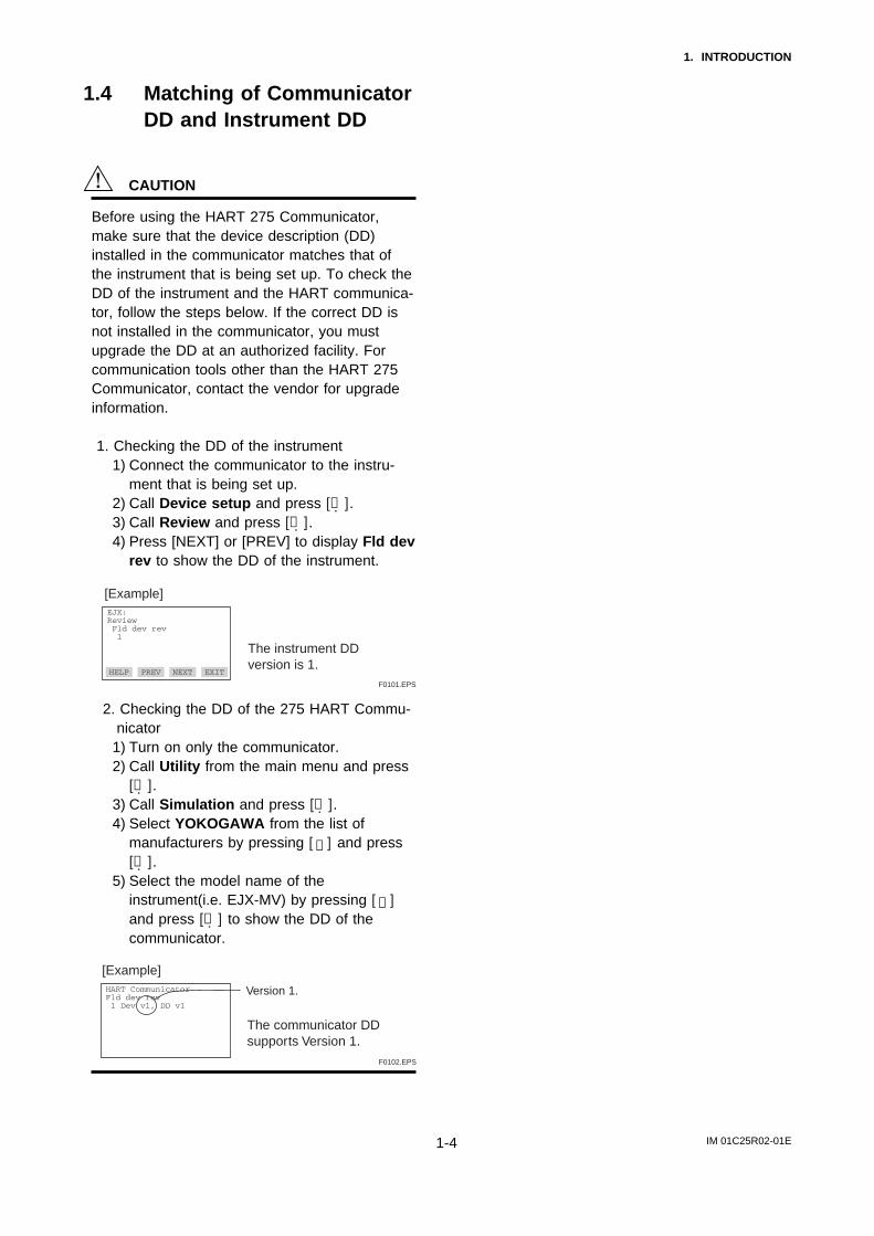
1.4 Matching of CommunicatorDD and Instrument DD
CAUTION
Before using the HART 275 Communicator,make sure that the device description (DD)installed in the communicator matches that ofthe instrument that is being set up. To check theDD of the instrument and the HART communica-tor, follow the steps below. If the correct DD isnot installed in the communicator, you mustupgrade the DD at an authorized facility. Forcommunication tools other than the HART 275Communicator, contact the vendor for upgradeinformation.
1. Checking the DD of the instrument1) Connect the communicator to the instru-
ment that is being set up.2) Call Device setup and press [→].3) Call Review and press [→].4) Press [NEXT] or [PREV] to display Fld dev
rev to show the DD of the instrument.
F0101.EPS
EJX:Review Fld dev rev 1
HELP PREV NEXT EXIT
The instrument DD version is 1.
[Example]
2. Checking the DD of the 275 HART Commu-nicator
1) Turn on only the communicator.2) Call Utility from the main menu and press
[→].3) Call Simulation and press [→].4) Select YOKOGAWA from the list of
manufacturers by pressing [ ]↓ and press[→].
5) Select the model name of theinstrument(i.e. EJX-MV) by pressing [ ]↓and press [→] to show the DD of thecommunicator.
F0102.EPS
HART CommunicatorFld dev rev 1 Dev v1, DD v1
[Example]
The communicator DD supports Version 1.
Version 1.
IM 01C25R02-01E2-1
2. CONDITIONS OF COMMUNICATION LINE
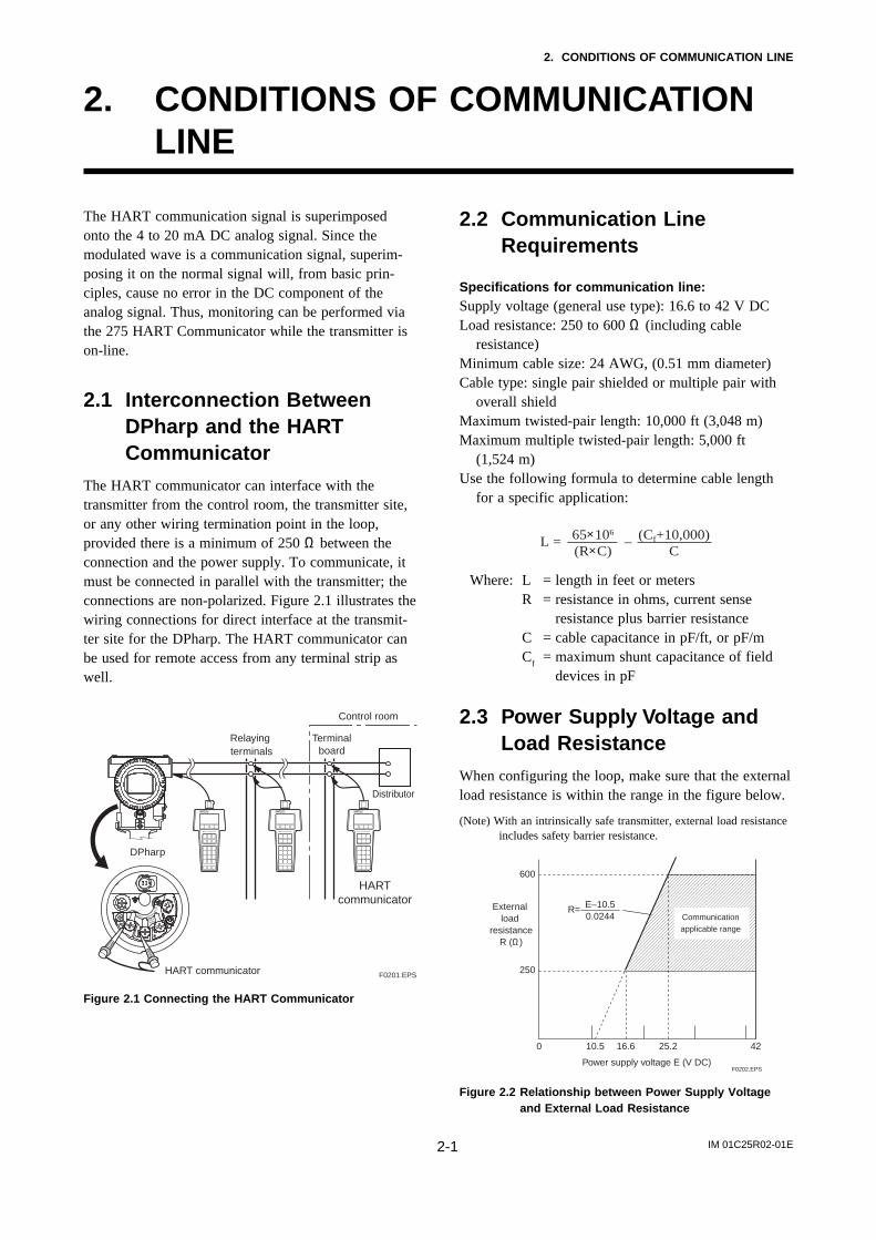
2. CONDITIONS OF COMMUNICATIONLINE
The HART communication signal is superimposedonto the 4 to 20 mA DC analog signal. Since themodulated wave is a communication signal, superim-posing it on the normal signal will, from basic prin-ciples, cause no error in the DC component of theanalog signal. Thus, monitoring can be performed viathe 275 HART Communicator while the transmitter ison-line.
2.1 Interconnection BetweenDPharp and the HARTCommunicator
The HART communicator can interface with thetransmitter from the control room, the transmitter site,or any other wiring termination point in the loop,provided there is a minimum of 250 Ω between theconnection and the power supply. To communicate, itmust be connected in parallel with the transmitter; theconnections are non-polarized. Figure 2.1 illustrates thewiring connections for direct interface at the transmit-ter site for the DPharp. The HART communicator canbe used for remote access from any terminal strip aswell.
SUPPLY
PULS
E
CHECK
ALARM
DPharp
Relaying terminals
Distributor
Control room
Terminalboard
F0201.EPS
HARTcommunicator
HART communicator
Figure 2.1 Connecting the HART Communicator
2.2 Communication LineRequirements
Specifications for communication line:Supply voltage (general use type): 16.6 to 42 V DCLoad resistance: 250 to 600 Ω (including cable
resistance)Minimum cable size: 24 AWG, (0.51 mm diameter)Cable type: single pair shielded or multiple pair with
overall shieldMaximum twisted-pair length: 10,000 ft (3,048 m)Maximum multiple twisted-pair length: 5,000 ft
(1,524 m)Use the following formula to determine cable length
for a specific application:
L = –65×106
(R×C)(Cf+10,000)
C
Where: L = length in feet or metersR = resistance in ohms, current sense
resistance plus barrier resistanceC = cable capacitance in pF/ft, or pF/mC
f= maximum shunt capacitance of field
devices in pF
2.3 Power Supply Voltage andLoad Resistance
When configuring the loop, make sure that the externalload resistance is within the range in the figure below.
(Note) With an intrinsically safe transmitter, external load resistanceincludes safety barrier resistance.
600
250
0 10.5 16.6 25.2 42
External load
resistanceR (Ω)
Power supply voltage E (V DC)F0202.EPS
Communication applicable range
R= E–10.50.0244
Figure 2.2 Relationship between Power Supply Voltageand External Load Resistance

IM 01C25R02-01E3-1
3. OPERATION
3. OPERATION3.1 Basic Operation of the 275 HART Communicator
3.1.1 Keys and Functions
LCD (liquid crystal display)
(21 characters×8 lines)
Communication cable
Function keys
Functions of the keys are indicated on the display.
Pressing (HOME) when the display is as shown changes the display to the Online menu. (See 3.1.2 Display.)
Hot key
Calls up settings menu 1. Keypad input 2. Wrt protect menu
Shift keys
Use to enter alphabetic characters.
1. Changes the display contents.2. Moves the position where characters are to be entered.
Pressing calls up the display corresponding to the highlighted item.
Pressing returns to the previous display. (See 3.1.3.)
Alphanumeric keys
1. Enters characters.2. Selects the desired menu item with the
corresponding number. (See 3.1.4.)
Pressing a key enters a number.Pressing a shift key and then analphanumeric key enters analphabetic character.
Moves the highlighting cursor on the display to select the desired item.
To enter 7,
To enter C,
7
C
(Press) (ENTER)
Power ON/OFF
F0301.EPS
EJX:Process variables 1 PV 0.000 kPa 2 PV % 0.00 % 3 PV AO 4.000 mA 4 Engr Disp 0 MPa 5 Engr exp 0.0 %HELP HOMESAVE
Figure 3.1 HART Communicator
IM 01C25R02-01E3-2
3. OPERATION
3.1.2 Display
The HART communicator searches for a transmitter onthe 4 to 20mA loop when it is turned on. When theHART communicator is connected to the transmitter,the Online menu (Top menu) is started automaticallyand the following display appears. If no transmitter isfound, select the Online menu.
Manufacturer’s transmitter type Tag (8 characters) <a>
<b>
<c>
<d>
<e>
Function keys
EJX :YOKOGAWAOnline 1 Device setup 2 PV 0.056 kPa 3 PV AO 4.009 mA 4 PV LRV 0.000 kPa 5 PV URV 100.000 kPa
F0302.EPS
The highlighting cursor
Arrows appear when the SHIFT key is pressed.
Appears when the voltage level of the battery is low.
SAVE
Figure 3.2 Display
<a> appears and flashes during communication
between the HART communicator and the
transmitter. At Burst mode, appears.
<b> The item selected from the previous menu.<c> The available items in the menu of <b>.
<d> or appears when the item is scrolled out of
the display.<e> Function labels corresponding to specific function
keys are displayed. These labels indicate thecurrently available choices.
Function Key Labels
F1
HELPaccess on-line
help
RETRYtry to re-establish
communication
EXITleave the
current menu
YESanswer to
yes/no question
ALLinclude current
Hot Key item on Hot Key Menu for all devices
F2
ON/OFFactivates or
deactivates a binary variable
DELdelete current
character or Hot Key Menu item
SENDsend data to
device, or mark data to send
PGUPmove up one help screen
PREVgo to previous message in a
list of messages
F3
ABORTterminate
current task
ESCleave value unchanged
QUITterminate session
because of a comunication
error
PGDNmove down one
help screen
NEXTgo to next
message in the list of messages
HOMEgo to the top menu in the
device description
SKIPdo not mark
variable to be sent in off-line configuration
ONEinclude Hot Key
item for one device
BACKgo back to menu from
which HOME was pressed
EDITedit a variable
value
ADDadd current item
to Hot Key Menu
SAVEsave information
to communicator
SENDsend data to
device, or mark data to send
F4
OKacknowledge information on
screen
ENTERaccept user-entered data
NEXTleave the
current menu
NOanswer to
yes/no question
F0303.EPS
3.1.3 Calling Up Menu Addresses
Subsection 3.3 Menu Tree shows the configuration ofall menu items available with the HART communica-tor. The desired item can be displayed with ease byunderstanding the menu configuration.
When the HART communicator is connected to thetransmitter, the Online menu will be displayed afterthe power is turned on. Call up the desired item asfollows:
Key operationThere are two choices to select the desired menu item.
1. Use the or key to select the desired item,
and then press the key.
2. Press the number displayed for the desired item.
To return to the previous display, press the key. If
ABORT , ESC and EXIT are displayed, press the
desired function key.
IM 01C25R02-01E3-3
3. OPERATION
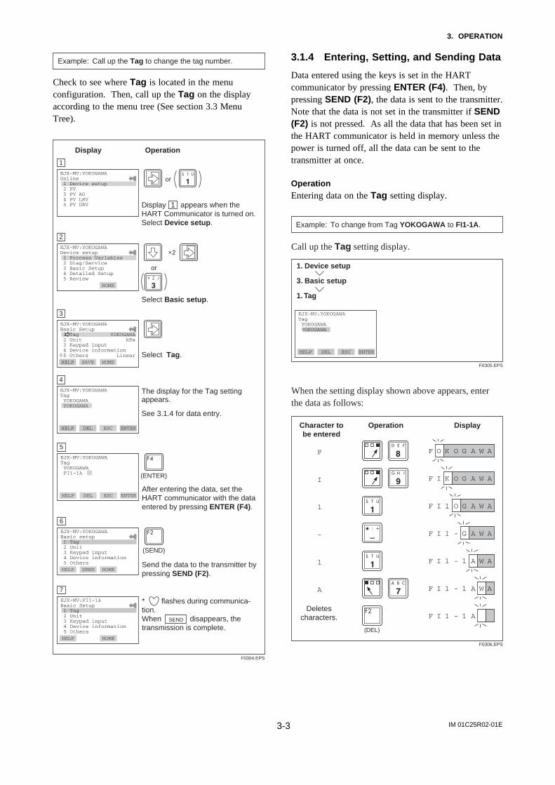
Example: Call up the Tag to change the tag number.
Check to see where Tag is located in the menuconfiguration. Then, call up the Tag on the displayaccording to the menu tree (See section 3.3 MenuTree).
1
F0304.EPS
Display appears when the HART Communicator is turned on.Select Device setup.
EJX-MV:YOKOGAWAOnline 1 Device setup 2 PV 3 PV AO 4 PV LRV 5 PV URVDEL SET ESC ENTER
Display Operation
or
EJX-MV:YOKOGAWADevice setup 1 Process Varlables 2 Diag/Service 3 Basic Setup 4 Detailed Setup 5 ReviewDEL SAVE HOME ENTER
×2
or
1
2
Select Basic setup.
EJX-MV:YOKOGAWABasic Setup 1 Tag YOKOGAWA 2 Unit kPa 3 Keypad input 4 Device information 5 Others LinearDEL SAVE HOME ENTER
3
Select Tag.HELP
EJX-MV:YOKOGAWATag YOKOGAWA YOKOGAWA
DEL ESC
4
The display for the Tag setting appears.
See 3.1.4 for data entry.
HELP DEL ENTER
5
After entering the data, set the HART communicator with the data entered by pressing ENTER (F4).
EJX-MV:YOKOGAWATag YOKOGAWA FI1-1A
6
Send the data to the transmitter by pressing SEND (F2).
7
* flashes during communica-tion.When disappears, the transmission is complete.
(ENTER)
(SEND)
HELP DEL ESC ENTER
EJX-MV:YOKOGAWABasic setup 1 Tag 2 Unit 3 Keypad input 4 Device information 5 OthersHELP SEND HOME ENTER
EJX-MV:FI1-1ABasic Setup 1 Tag 2 Unit 3 Keypad input 4 Device information 5 OthersHELP SAVE HOME ENTER
SEND
3.1.4 Entering, Setting, and Sending Data
Data entered using the keys is set in the HARTcommunicator by pressing ENTER (F4). Then, bypressing SEND (F2), the data is sent to the transmitter.Note that the data is not set in the transmitter if SEND(F2) is not pressed. As all the data that has been set inthe HART communicator is held in memory unless thepower is turned off, all the data can be sent to thetransmitter at once.
OperationEntering data on the Tag setting display.
1. Device setup
3. Basic setup
1. Tag
F0305.EPS
EJX-MV:YOKOGAWATag YOKOGAWA YOKOGAWA
HELP DEL ESC ENTER
Example: To change from Tag YOKOGAWA to FI1-1A.
Call up the Tag setting display.
F0306.EPS
F O K O G A W A
F I K O G A W A
F I 1 O G A W A
F I 1 - G A W A
F I 1 - 1 A W A
F I 1 - 1 A W A
F I 1 - 1 A
F
I
1
-
1
A
Character tobe entered
Operation Display
Deletescharacters.
(DEL)
When the setting display shown above appears, enter the data as follows:

IM 01C25R02-01E3-4
3. OPERATION
3.2 Parameter Usage andSelection
Before setting a parameter, please see the followingtable for a summary of how and when each parameteris used.
IMPORTANT
After setting and sending data with the HARTcommunicator, wait 30 seconds before turningoff the transmitter. If it is turned off too soon, thesettings will not be stored in the transmitter.
Table 3.1 Parameter Usage and SelectionITEM HART communicator PageDescription
Memory
Unit
Transmitter
Display
HART output
Adjustment
Maintenance
Monitoring
Tag
P. 3-10
P. 3-11
P. 3-12
P. 3-28
P. 3-21
P. 3-16
P. 3-26
P. 3-31
P. 3-31
P. 3-33
P. 3-17
P. 3-21
P. 3-24
P. 4-1
—
P. 3-13
P. 3-14
P. 3-20
P. 3-19
P. 3-15
P. 3-18
Tag number, up to 8 characters
Descriptor Up to 16 characters
Message Up to 32 characters
Date xx/yy/zz
PV Unit Sets a PV unit for the measured pressure displayed on HART communicator
Pres Unit Sets a differential pressure unit for the measured pressure displayed on HART communicator
SP Unit Sets a static pressure unit for the measured pressure displayed on HART communicator
ET Unit Sets a external temperature unit for the measured pressure displayed on HART communicator
Flow Unit Sets a flow unit for the measured pressure displayed on HART communicator
Total Flow Unit Sets a total flow unit for the measured pressure displayed on HART communicator
PV LRV/URV Sets the calibration range by the keypad
PV Damp
Range
Engr disp range Sets Engr Unit/Modify Engr Unit/Engr LRV/Engr URV/Engr point/Engr expIntegral indicator scale
Loop test Used for loop checks. Output can be set freely from -2.5% to 110% in 1% stepsTest output
Pres, SP, and ET trim Adjusts the measured differential pressure, static pressure, and external temperature variablesSensor trim
D/A trim, Scaled D/A trim Adjusts the output value at the points of 4 mA and 20 mAAnalog output trim
Special Flow Base Density Sets volume flow base densityFlow Base Density
Fixed ET ON/OFF switching of external temperature fixation modeExt. Temp Fixation
Config user unit Configures user unit for total flowUser unit for total flow
Simimulation Flow calculation by pseudo DP, SP, and ET valueSimulation Mode
Basic Flow Calc For manual setting of flow factor parameters. (The flow factor is a constant value)Basic Flow Mode
Process Alerts Used for alarm generation on the integral indicatorProcess alarm
Damping time constant
Output signal low cutmode
Impulse line connection orientation
Multidrop mode
Adjusts the output response speed for the input pressure of differential pressure
Low cut mode Off or On
Low Cut Used mainly to stabilize output near 0. Two modes are available: forcing output to 0% for input below a specific value, or changing to proportional output for input below a specific value
Burst mode ON/OFF switching of burst mode
Polling ON/OFF switching of multidrop mode
Poll addr Sets the polling address (1 to 15)
PV AO 4 to 20 mA output variable
PV and PV % Primary variable and % output variable
Pres Differential Pressure variable
Flow Flowing quantity calculated from differential pressure, static pressure, and external temperature
ET External temperature
SP Static pressure variable
Engr Disp/exp/Unit Displays the output of user setting engineering information
Total Flow Integrated value of flowing quantity
Write protect Displays the permit/protection status of setting changes depending on communications
New password Sets a new password
Enable wrt 10min Write protection status is released for 10 minutes when the password is entered
Burst option Selection of the data to be sent continuously (PV, % range/current, Process vars/crnt, or Xmtr Variables)
H/L Swap Used where installation conditions make it imperative to connect high pressure side impulse line to low pressure side of transmitter
Self-diagnostics Self test and Status Check using the self-test and status command. If an error is detected, the corresponding message is displayed
Output when CPU error has occurred
AO Alm typ Displays the status of 4 to 20 mA DC output when a failure occurs
External volumeprotect/permit
Software Write Protect
Ext SW Displays/sets the external volume protect/permit for LRV (URV) setting
Integral indicator display mode
Burst mode
Disp selectSets the following 7 types of integral indicator scale ranges and unit: % of PV range, flow, input differential pressure, input static pressure, input ext. temp, user set scaled PV, and total flow, and alternating among any four of the above
T0301.EPS
IM 01C25R02-01E3-5
3. OPERATION
3.3 Menu Tree
1 Device setup2 PV3 PV AO4 LRV5 URV
1 Process variables2 Diag/Servic3 Basic setup4 Detailed setup5 Review
Hot key 1 Keypad input
2 Wrt protect menu
1 PV is2 Change PV Assgn3 PV Unit4 PV LRV5 PV URV6 PV Damp
1 Write protect2 Enable wrt 10min3 New password4 Software seal
Online (Device setup)ABCD, E
1 Process variables 1 PV2 PV %3 PV AO4 Engr Disp5 Engr exp6 Engr Unit7 View fld dev vars
8 Output vars
A 1 Flow2 Pres3 SP4 ET5 Total Flow6 Cap temp7 Amp temp
1 PV
2 SV
3 TV
4 4V
1 PV is2 Change PV Assgn3 PV4 PV Unit
1 SV is2 Change SV Assgn3 SV4 SV Unit
1 TV is2 Change TV Assgn3 TV4 TV Unit
1 4V is2 Change 4V Assgn3 4V4 4V Unit
1 Flow2 Pres3 SP4 ET
1 Flow2 Pres3 SP4 ET
1 Flow2 Pres3 SP4 ET
1 Flow2 Pres3 SP4 ET
F0303a.EPS
IM 01C25R02-01E3-6
3. OPERATION
2 Diag/Service 1 Status
2 Test
3 Calibration
4 Error log
B 1 Status group 12 Status group 23 Status group 34 Status group 45 Status group 56 Status group 67 Status group 78 Status group 8
1 Keypad input
2 Analog output trim
3 Pres sensor trim
4 SP sensor trim
5 ET sensor trim
6 Trim info.
1 Loop test2 Self test3 Master test
F0303b.EPS
1 Error log view2 Error log Clear
1 PV is2 Change PV Assgn3 PV Unit4 PV LRV5 PV URV6 PV Damp
1 D/A trim2 Scaled D/A trim3 Clear D/A trim
1 Pres trim2 Clear P trim
1 SP trim2 Clear SP trim
1 ET trim2 Clear ET trim
1 Trim Who2 Trim Date3 Trim Loc4 Trim Desc

IM 01C25R02-01E3-7
3. OPERATION
3 Basic setup 1 Tag
2 Units
3 Keypad input
4 Device infomation
5 Others
C
1 Pres Unit2 SP Unit3 ET Unit4 Flow Unit5 Total Flow Unit
F0303c.EPS
1 PV is2 Change PV Assgn3 PV Unit4 PV LRV5 PV URV6 PV Damp
1 Date2 Descriptor3 Message4 Write Protect5 Model
1 Low cut2 Low cut mode3 H/L Swap

IM 01C25R02-01E3-8
3. OPERATION
4 Detailed setup
5. Review
1 Sensors
2 Signal condition
3 Output condition
4 Display condition5 Device information6 Test Key7 Simulation8 Basic Flow Calc
D 1 Pres2 SP3 Cap temp4 Amp temp5 ET
1 Flow Setup
2 DP Setup3 SP Setup4 ET Setup
5 Total Flow
6 Others
1 Flow LRV2 Flow URV3 Flow Unit4 Flow Damp
F0303d.EPS
1 Process variables
2 Analog output
3 HART output
4 Process Alerts
1 ET LRV2 ET URV3 ET Unit4 ET LSL5 ET USL6 ET Min span7 ET Damp8 Fixed ET
1 Total Flow2 Total Flow Unit3 Pulse rate4 Freq at 100%5 Total Flow Mode6 Config User Unit
1 Low cut2 Low cut mode3 H/L Swap
1 Loop test2 D/A trim3 Scaled D/A trim4 Clear D/A trim5 AO alm typ6 Auto recover7 AO lower limit8 AO upper limit
1 Pres LRV2 Pres URV3 Pres Unit4 Pres LSL5 Pres USL6 Pres Min span7 Pres Damp
1 SP LRV2 SP URV3 SP Unit4 SP LSL5 SP USL6 SP Min span7 SP Damp8 A/G Select9 SP H/L Select Atm. Pres Value Auto Atm.
1 ET Fixed2 Fixed ET Val
1 Cvt Val2 Set Base Unit3 Modify Unit
1 PV2 PV %3 PV AO4 Engr Disp5 Engr exp6 Engr Unit7 Digital Output
1 Poll addr2 Num req preams3 Burst mode4 Burst option5 Burst Xmtr Vals
1 Digital Output2 DO Select3 DO Signal type4 DO Test5 DO Frequency
1 Pres Alert2 SP Alert3 ET Alert4 Flow Alert5 DO Config
IM 01C25R02-01E3-9
3. OPERATION
4 Detailed setup
5. Review
1 Sensors2 Signal condition3 Output condition4 Display condition
5 Device information
6 Test Key
7 Simulation
8 Basic Flow Calc
E
1 Disp select
2 Disp % Reso
3 Disp condition
4 Engr disp range
5 Bar Indicator
1 Disp12 Disp23 Disp34 Disp4
F0303e.EPS
1 Field device info
2 Sensor infomation
3 Self test
1 Flow Calc mode2 Fluid Type3 Flow Calc Fixed4 Ref SP5 Ref Temp6 Temp K1
1 Style No.2 Serial No.3 Mftr Date4 Extra No.5 Final asmbly num6 Dev id7 Distributor8 PT100 Serial No.
1 Tag2 Date3 Descriptor4 Message5 MS Code 16 MS Code 27 MS Code 38 Write Protec9 Ext SW Revision #s
Additional Info
1 Isoltr matl2 Fill fluid3 Gasket matl4 Process Conn5 Drain vent matl6 Process Conn type7 RS Isoltr matl8 Process Conn size9 Num of RSRS fill fluidRS type
1 Universal rev2 Fld dev rev3 Software rev
1 Engr LRV2 Engr URV3 Engr exp4 Engr Unit5 Engr point6 Set Engr Unit7 Modify Engr Unit
1 Simulation 2 Sim Pres Unit3 Sim Pres4 Sim SP Unit5 Sim SP6 Sim Temp Unit7 Sim Temp
1 Flow disp point2 Pres disp point3 SP disp point4 ET disp point5 TF disp point
IM 01C25R02-01E3-10
3. OPERATION
3.4 Basic Setup
3.4.1 Tag and Device Information
To change the Tag No., see section 3.1.4 Entering,Setting, and Sending Data.
Up to 8 characters can be set with Tag. The maximumnumber of characters to be set for other items is asshown below.
Item Number of characters
T0302.EPS
TagDescriptorMessage
Date
81632
2/2/2
1. Device setup
3. Basic setup
1. Tag
EJX:YOKOGAWATag YOKOGAWA YOKOGAWA
HELP DEL ESC ENTER
(1) Tag
1. Device setup
3. Basic setup
4. Device information
2. Descriptor
EJX:YOKOGAWADescriptor
HELP DEL ESC ENTER
(2) Descriptor
1. Device setup
3. Basic setup
4. Device information
3. Message
EJX:YOKOGAWAMessage
HELP DEL ESC ENTER
(3) Message
1. Device setup
3. Basic setup
4. Device information
4. Date
EJX:YOKOGAWADate **/**/** **/**/**
HELP ESC ENTER
(4) Date
F0308.EPS
3.4.2 Process Variable Setup
(1) Changing the allocation to PVSee 3.4.3(1) Changing the allocation to PV.
(2) Changing the allocation to SV
Example: To set SV to Pres.
Call up the Change SV assgn display.
1
F0308a.EPS
EJX-MV:YOKOGAWACurrent SV is PresSelect new SV1 Flow2 Pres3 SP4 ET
DEL SET ABORT ENTER Select Pres and press ENTER (F4).
(ENTER)
1. Device setup
1. Process variables
8. Output vars
2. SV
2. Change SV assgn
(3) Changing the allocation to TV
Example: To set TV to SP.
Call up the Change TV assgn display.
1
F0308b.EPS
EJX-MV:YOKOGAWACurrent SV is PresSelect new SV1 Flow2 Pres3 SP4 ET
DEL SET ABORT ENTER Select SP and press ENTER (F4).
(ENTER)
1. Device setup
1. Process variables
8. Output vars
2. TV
2. Change TV assgn
(4) Changing the allocation to 4V
Example: To set 4V to ET.
Call up the Change 4V assgn display.
1
F0308c.EPS
EJX-MV:YOKOGAWACurrent 4v is SPSelect new 4v1 Flow2 Pres3 SP4 ET
DEL SET ABORT ENTER Select ET and press ENTER (F4).
(ENTER)
1. Device setup
1. Process variables
8. Output vars
2. 4V
2. Change 4V assgn
IM 01C25R02-01E3-11
3. OPERATION
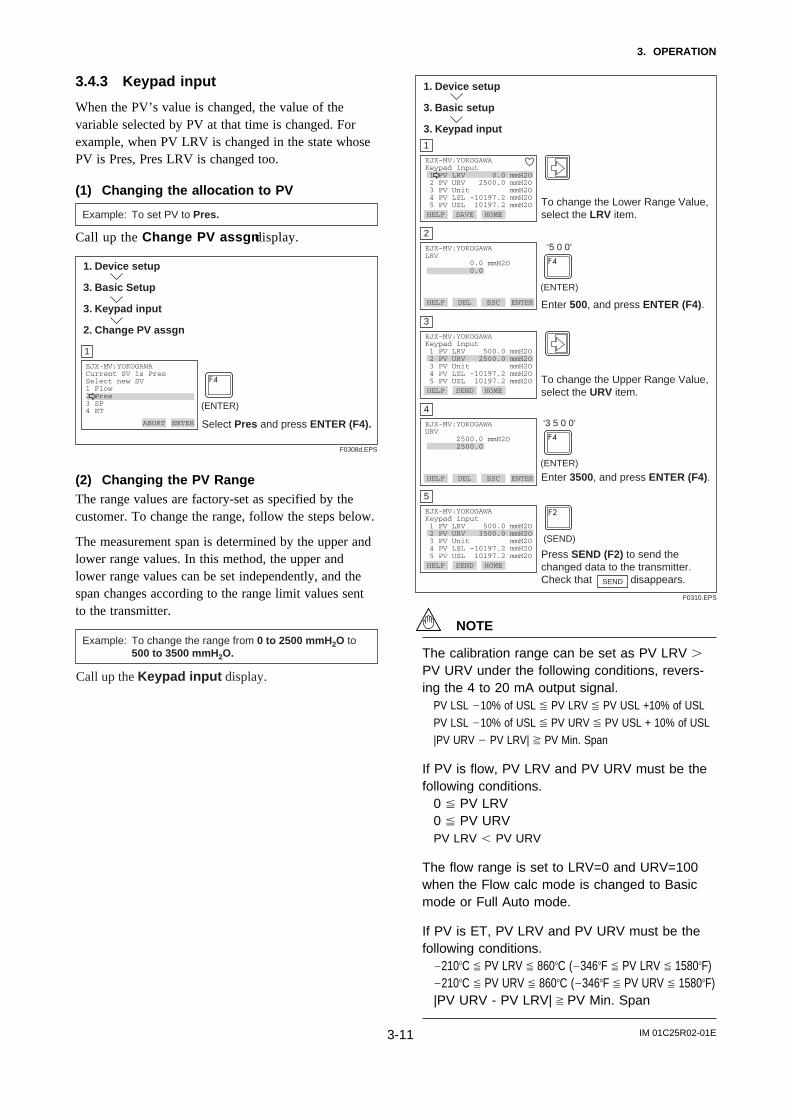
3.4.3 Keypad input
When the PV’s value is changed, the value of thevariable selected by PV at that time is changed. Forexample, when PV LRV is changed in the state whosePV is Pres, Pres LRV is changed too.
(1) Changing the allocation to PV
Example: To set PV to Pres.
Call up the Change PV assgn display.
1
F0308d.EPS
EJX-MV:YOKOGAWACurrent SV is PresSelect new SV1 Flow2 Pres3 SP4 ET
DEL SET ABORT ENTER Select Pres and press ENTER (F4).
(ENTER)
1. Device setup
3. Basic Setup
3. Keypad input
2. Change PV assgn
(2) Changing the PV RangeThe range values are factory-set as specified by thecustomer. To change the range, follow the steps below.
The measurement span is determined by the upper andlower range values. In this method, the upper andlower range values can be set independently, and thespan changes according to the range limit values sentto the transmitter.
Example: To change the range from 0 to 2500 mmH2O to 500 to 3500 mmH2O.
Call up the Keypad input display.
1
F0310.EPS
EJX-MV:YOKOGAWAKeypad input 1 PV LRV 0.0 mmH2O 2 PV URV 2500.0 mmH2O 3 PV Unit mmH2O 4 PV LSL -10197.2 mmH2O 5 PV USL 10197.2 mmH2OHELP SAVE HOME ENTER
EJX-MV:YOKOGAWALRV 0.0 mmH2O 0.0
HELP DEL ESC ENTER
2
Enter 500, and press ENTER (F4).
EJX-MV:YOKOGAWAKeypad input 1 PV LRV 500.0 mmH2O 2 PV URV 2500.0 mmH2O 3 PV Unit mmH2O 4 PV LSL -10197.2 mmH2O 5 PV USL 10197.2 mmH2ODEL HOME
3
To change the Upper Range Value, select the URV item.
To change the Lower Range Value, select the LRV item.
HELP SEND ENTER
(ENTER)
‘3 5 0 0’
(ENTER)
‘5 0 0’
(SEND)
EJX-MV:YOKOGAWAURV 2500.0 mmH2O 2500.0
HELP ESC
4
Enter 3500, and press ENTER (F4).DEL ENTER
EJX-MV:YOKOGAWAKeypad input 1 PV LRV 500.0 mmH2O 2 PV URV 3500.0 mmH2O 3 PV Unit mmH2O 4 PV LSL -10197.2 mmH2O 5 PV USL 10197.2 mmH2OHELP HOME
5
Press SEND (F2) to send the changed data to the transmitter.Check that disappears.
SEND ENTER
SEND
1. Device setup
3. Basic setup
3. Keypad input
NOTE
The calibration range can be set as PV LRV PV URV under the following conditions, revers-ing the 4 to 20 mA output signal.
PV LSL 10% of USL PV LRV PV USL +10% of USL
PV LSL 10% of USL PV URV PV USL + 10% of USL
|PV URV PV LRV| PV Min. Span
If PV is flow, PV LRV and PV URV must be thefollowing conditions.
0 PV LRV0 PV URVPV LRV PV URV
The flow range is set to LRV=0 and URV=100when the Flow calc mode is changed to Basicmode or Full Auto mode.
If PV is ET, PV LRV and PV URV must be thefollowing conditions.
210!C PV LRV 860!C (346!F PV LRV 1580!F)210!C PV URV 860!C (346!F PV URV 1580!F)|PV URV - PV LRV| PV Min. Span

IM 01C25R02-01E3-12
3. OPERATION
(3) PV UnitThe “PV unit” parameter is set at the factory beforeshipment if specified at the time of order. Follow theprocedure below to change the unit parameter.
Depending on the current setting for PV, changing thisparameter also changes the unit for either differentialpressure, static pressure, external temperature or flowdisplay.
(4) PV DampThe damping time constant is set as specified in theorder when the instrument is shipped. Follow theprocedure below to change the damping time constant.The damping time constant for the amplifier assemblycan be set here. The damping time constant for theentire transmitter is the sum of the values for theamplifier assembly and the capsule assembly.
Any number from 0.00 to 100.00 can be set for thedamping time constant.
Example: To change from 2.0 seconds to 0.5 seconds.
1
F0313.EPS
Call up the PV Damp display.
EJX-MV:YOKOGAWAPV Damp 2.00 sec 0.5
HELP DEL ESC ENTER Enter 0.5 and press ENTER (F4).
(ENTER)
‘0 . 5’
2
EJX-MV:YOKOGAWAKeypad Input 2 Change PV assgn 3 PV Unit kPa 4 PV LRV kPa 5 PV URV 0.50 kPa 6 PV Damp 10.00 secHELP SEND HOME ENTER
Press SEND (F2) to send the data to the transmitter.
1. Device setup
3. Basic setup
3. Keypad Input
6. PV Damp
3.4.4 Units
(1) Pres UnitThe “Pres Unit” parameter is set at the factory beforeshipment if specified at the time of order. Follow theprocedure below to change the unit parameter.
Changing this parameter also changes the unit for thedifferential pressure display.
F0309.EPS
EJX-MV:YOKOGAWAPres UnitmmH2O MPa inH2O mmH2O ftH2ODEL SAVE ESC ENTER
1
Select the desired unit and press ENTER (F4).
HELP (ENTER)
Example: To change the unit from mmH2O to inH2O
EJX-MV:YOKOGAWAUnits 1 Pres Unit YOKOGAWA 2 SP Unit mmH2O 3 ET Unit 4 Flow Unit 5 Total Flow UnitDEL
2
HELP SEND HOME ENTER
(SEND)
1. Device setup
3. Basic setup
2. Units
1. Pres Unit
Press SEND (F2) to send the data to the transmitter, then check to confirm that disappears.SEND
Note that the Yokogawa default setting for the standardtemperature is 4!C (39.2!F). For the units of mmH
2O,
inH2O, and ftH
2O, the pressure varies according to the
standard temperature definition. Select the appropriateunit with @68degF when a standard temperature of20!C (68!F) is required.
Available pressure units are shown below.
T0303.EPS
inH2O@68degF mbar MPa
inHg g/cm2 inH2O
ftH2O@68degF kg/cm2 mmH2O
mmH2O@68degF Pa ftH2O
mmHg kPa hPa
psi torr
bar atm

IM 01C25R02-01E3-13
3. OPERATION
(2) SP UnitFollow the procedure to change the static pressure unit.
Changing this parameter also changes the unit for thestatic pressure display.
F0324.EPS
(ENTER)
EJX-MV:YOKOGAWASP UnitmmH2O kg/cm2 Pa kPa torrHELP SEND ESC ENTER
Select kPa and Press ENTER (F4).
1. Device setup
3. Basic setup
2. Units
3. SP Unit
Example: Change the static pressure unit from mmH2O to kPa.
EJX-MV:YOKOGAWA Units 1 Pres Unit 0 mmH2O 2 SP Unit 0.0 % 3 ET Unit kPa 4 Flow Unit 5 Total Flow UnitHELP SEND HOME ENTER
2
1
Press SEND (F2) to send the data to the transmitter, then check to confirm that disappears.
(SEND)
SEND
Available pressure units are shown below.
T0303.EPS
inH2O@68degF mbar MPa
inHg g/cm2 inH2O
ftH2O@68degF kg/cm2 mmH2O
mmH2O@68degF Pa ftH2O
mmHg kPa hPa
psi torr
bar atm
(3) ET UnitWhen the instrument is shipped, the ET (externaltemperature) units are set to degC. Follow theprocedure below to change this setting.
When this parameter is set, it also changes the tem-perature unit for ET, Cap temp, and Amp temp atProcess variables .
F0323.EPS
(ENTER)
EJX-MV:YOKOGAWAET UnitdegC degC degF Kelvin
SEND ESC ENTER
Select degF (Fahrenheit), and Press ENTER (F4).
1. Device setup
3. Basic setup
2. Units
3. ET Unit
Example: Change the unit for the temperature display from degC to degF.
EJX-MV:YOKOGAWA Units 1 Pres Unit 23 degC 2 SP Unit 23 degC 3 ET Unit degF 4 Flow Unit 5 Total Flow UnitHELP SEND HOME ENTER
2
1
Press SEND (F2) to send the data to the transmitter, then check to confirm that disappears.
(SEND)
SEND
HELP
Available temperature units are degC, degF, andKelvin .
IM 01C25R02-01E3-14
3. OPERATION
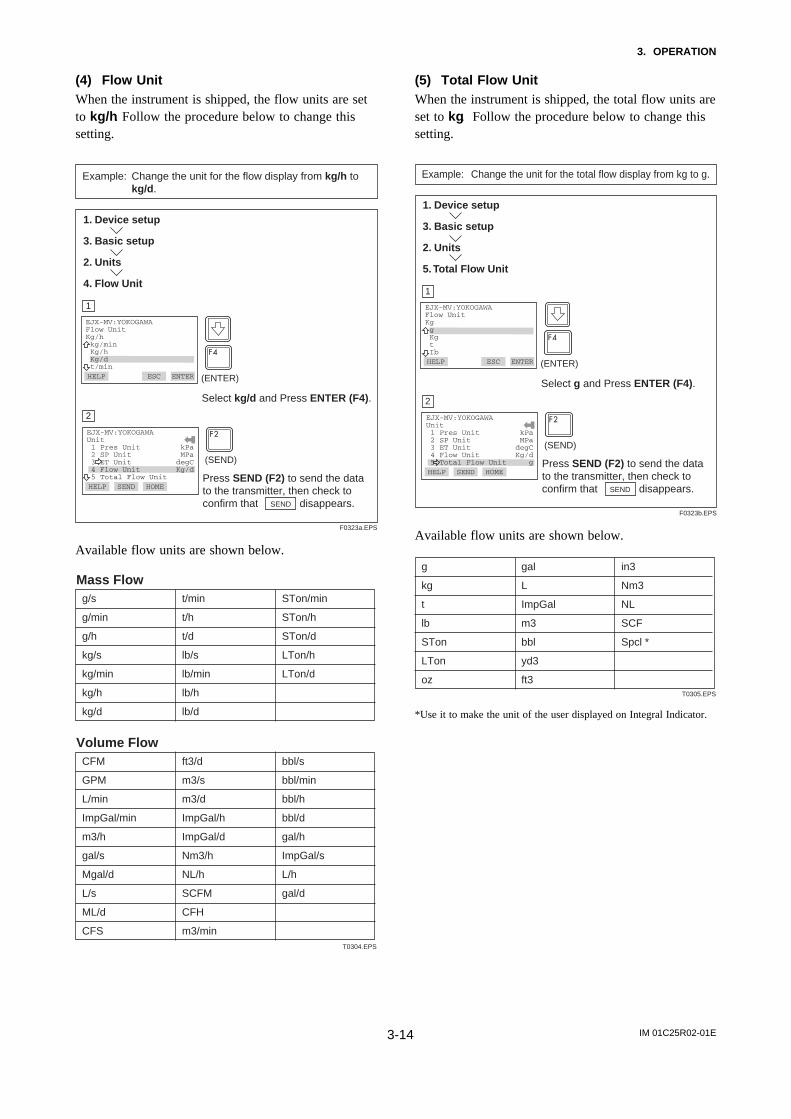
(4) Flow UnitWhen the instrument is shipped, the flow units are setto kg/h. Follow the procedure below to change thissetting.
F0323a.EPS
(ENTER)
EJX-MV:YOKOGAWAFlow UnitKg/h kg/min Kg/h Kg/d t/minHELP SEND ESC ENTER
Select kg/d and Press ENTER (F4).
1. Device setup
3. Basic setup
2. Units
4. Flow Unit
Example: Change the unit for the flow display from kg/h to kg/d.
EJX-MV:YOKOGAWA Unit 1 Pres Unit kPa 2 SP Unit MPa 3 ET Unit degC 4 Flow Unit Kg/d 5 Total Flow UnitHELP SEND HOME ENTER
2
1
Press SEND (F2) to send the data to the transmitter, then check to confirm that disappears.
(SEND)
SEND
Available flow units are shown below.
T0304.EPS
g/s t/min STon/min
g/min t/h STon/h
g/h t/d STon/d
kg/s lb/s LTon/h
kg/min lb/min LTon/d
kg/h lb/h
kg/d lb/d
Mass Flow
CFM ft3/d bbl/s
GPM m3/s bbl/min
L/min m3/d bbl/h
ImpGal/min ImpGal/h bbl/d
m3/h ImpGal/d gal/h
gal/s Nm3/h ImpGal/s
Mgal/d NL/h L/h
L/s SCFM gal/d
ML/d CFH
CFS m3/min
Volume Flow
(5) Total Flow UnitWhen the instrument is shipped, the total flow units areset to kg. Follow the procedure below to change thissetting.
F0323b.EPS
(ENTER)
EJX-MV:YOKOGAWAFlow UnitKg g Kg t IbHELP SEND ESC ENTER
Select g and Press ENTER (F4).
1. Device setup
3. Basic setup
2. Units
5. Total Flow Unit
Example: Change the unit for the total flow display from kg to g.
EJX-MV:YOKOGAWA Unit 1 Pres Unit kPa 2 SP Unit MPa 3 ET Unit degC 4 Flow Unit Kg/d 5 Total Flow Unit gHELP SEND HOME ENTER
2
1
Press SEND (F2) to send the data to the transmitter, then check to confirm that disappears.
(SEND)
SEND
Available flow units are shown below.
T0305.EPS
g gal in3
kg L Nm3
t ImpGal NL
lb m3 SCF
STon bbl Spcl *
LTon yd3
oz ft3
*Use it to make the unit of the user displayed on Integral Indicator.

IM 01C25R02-01E3-15
3. OPERATION
3.4.5 Output Signal Low Cut Mode Setup
Low cut mode can be used to stabilize the outputsignal near the zero point.
The low cut point in set with differential pressure range.The range can be set from 0 to 20 %. (Hysteresis:±10% of the cut point)
Either ON or OFF can be selected as the low cutmode. Unless otherwise specified, the cut mode is setto OFF at the factory.
Example: To set the low cut range to 20% and the cut mode to ZERO in the Pres output, proceed as follows.
(%)50
(%)50
0 50(%)
50(%)
DP
Out
put
DP
Out
put
For low cut in off mode
Input
2020
0
For low cut in on mode
Input
F0315a.EPS
Figure 3.3 Low Cut Mode
F0315.EPS
EJX-MV:YOKOGAWALow cut 10.00 % 10.00
DEL ESC ENTER Call up Low cut, and set to 20%.
(ENTER)
(ENTER)
‘2 0’
EJX-MV:YOKOGAWALow cut modeOff Off On
HELP SEND ESC ENTER
Select the Low cut mode, and set to on.
EJX-MV:YOKOGAWAOthers 1 Low cut 2 Low cut mode on 3 H/L Swap Normal
HELP SEND HOME OKPress SEND (F2) to send the date, then check to confirm that disappears.
(SEND)
1. Device setup
3. Basic setup
5. Others
1. Low Cut and 2. Low cut mode
SEND
1
2
3
HELP
3.4.6 Impulse Line Connection OrientationSetup
This function reverses the impulse line orientation.Follow the procedure below to make this change.
F0316.EPS
(ENTER)
EJX-MV:YOKOGAWAH/L SwapNormal Normal Reverse
HELP SEND ESC ENTER
Press SEND (F2) to send the data to the transmitter, then check to confirm that disappears.
(SEND)
1. Device setup
3. Basic setup
5. Others
3. H/L Swap
SEND
Call up the H/L Swap Display Select Reverse, and press ENTER (F4).
EJX-MV:YOKOGAWAOthers 1 Low cut 20.00 % 2 Low cut mode 0.50 sec 3 H/L Swap Reverse
HELP SEND HOME
Example: Assign the high pressure impulse line connection to the L side of the transmitter.
1
2
3.5 Detailed SetupFlow and total flow can be displayed as a calculatedvalue. Pressure, static pressure, and external tempera-ture can be displayed as a measured input. Selected onevalue can be output by the 4-20 mA signal for mea-sured PV.
3.5.1 Signal Condition
a. Flow SetupThe Flow Setup parameters allow the setting of therange, unit, and damping time constant for the flow.
b. DP SetupThe DP Setup parameters allow the setting of therange, unit, and damping time constant for the differen-tial pressure.
c. SP SetupThe SP Setup parameters allow the setting of therange, unit, and damping time constant for the staticpressure.

IM 01C25R02-01E3-16
3. OPERATION
Note either the high or low pressure side of the capsulecan be selected to monitor the static pressure by SP H/L Select parameter.
d. ET SetupThe ET Setup parameters allow the setting of therange, unit, and damping time constant for the externaltemperature.
You can set Fixed ET and Fixed ET val. See 3.5.2External. Temperature Fixation Mode.
e. Total FlowThe Total Flow parameters allow the setting of theunit for the total flow, the scaled pulse rate, and totalflow measuring mode.
You can set and modify special unit for total flow.
F0316a.EPS
(ENTER)
EJX-MV:YOKOGAWATotal Flow ModeReset Reset Start Stop
HELP SEND ESC ENTER
Press SEND (F2) to send the changed data to the transmitter. Check that disappears.
(SEND)
1. Device setup
4. Detailed setup
2. Signal condition
5. Total Flow
5. Total Flow Mode
SEND
Select Start, and press ENTER (F4).
EJX-MV:YOKOGAWATotal Flow 1 Total Flow 2 Total Flow Unit 3 Pulse rate 4 Freq at 100% 5 Total Flow ModeHELP SEND HOME
Example: To start total flow measuring.
1
2
To stop total flow measuring, call up the Total FlowMode display and set Stop.
To reset total flow value, call up the Total FlowMode display and set Reset.
3.5.2 External Temperature Fixation ModeThe external temperature can be fixed with this mode.
1
F0323b-2.EPS
To adjust external temperature fixation value to 15!C, select the Fixed ET Val item.
EJX-MV:YOKOGAWAFixed ET 1 ET Fixed No 2 Fixed Et Val
SET HOME
EJX-MV:YOKOGAWAFixed ET Val 20degC 15.0
2
2
EJX-MV:YOKOGAWAFixed ET 1 ET Fixed No 2 Fixed Et Val
HELP SAVE
SAVEHELP
HOME
3
To enable fixation mode, select the ET Fixed item.
Enter 15.0, and press ENTER (F4).
Select Yes and press ENTER (F4).
EJX-MV:YOKOGAWAFixed ETNo No Yes FALL BACK
DEL
4
HELP
HELP DEL ESC ENTER
ESC ENTER
or
EJX-MV:YOKOGAWAFixed ET 1 ET Fixed Yes 2 Fixed ET Val
HOME
5
Press SEND (F2) to send the changed data to the transmitter. Check that disappears.
HELP SEND
Example: The external temperature is fixed at 15!C.
1. Device setup
4. Detailed setup
2. Signal condition
4. ET Setup
8. Fixed ET
(SEND)
SEND
(ENTER)
(ENTER)
To release fixation mode, call up the ET Fixed displayand set No.

IM 01C25R02-01E3-17
3. OPERATION
3.5.3 User unit configuration for total flow
Config User Unit parameters allow the special unitfor total flow and scale to be displayed. At Set BaseUnit, the following special units can be selected from alist.Alternately, up to eight alphanumeric characters, spacesor slashes (/) can be input on the keypad at ModifyUnit; only the first six are displayed on the integralindicator.
Select the unit from the Set Base Unit list.
T0306.EPS
g oz yd3
kg gal ft3
t L In3
lb Impgal Nm3
STon m3 NL
SCFLTon bbl
1
F0323c.EPS
Call up the Set Base Unit, select SCF, and press ENTER (F4).This method ends automatically.
Call up the Modify Unit.
EJX-MV:YOKOGAWAConfig User Unit 1 Cvt Val 1 2 Set Base Unit 3 Modify Unit
SET HOME
EJX-MV:YOKOGAWAConfig User Unit 1 Cvt Val 1 2 Set Base Unit 3 Modify Unit
2
EJX-MV:YOKOGAWAEnter Unit SCF MMSCF
HELP DEL
SEND
HOMEHELP SEND
ABOUT
3
Set MMSCF, and press ENTER (F4).
EJX-MV:YOKOGAWACvt Val 1 1000000
DEL HOME
4
HELP
ENTER
EJX-MV:YOKOGAWAConfig User Unit 1 Cvt Val 2 Set Base Unit 3 Modify Unit
HOME
5
Press SEND (F2) to send the changed data to the transmitter. Check that disappears.
Call up the Cvt Val.Set the conversion value of a special unit to a base unit.
HELP SEND
Example: Set the special total flow unit as MMSCF based SCF.
1. Device setup
4. Detailed setup
2. Signal condition
5. Total Flow
6. Config User Unit
(SEND)
SEND
SEND
7
8
3.5.4 Integral Indicator Scale Setup
The following seven displays are available for integral
indicators: % of PV range, flow, input differentialpressure, input static pressure, input ext. temp, user setscaled PV, and total flow. A cycle of up to fourdisplays can be shown by assigning variables to theparameters at Disp select.
T0306-2.EPS
Available displays Description and related parameters
% of PV range(PV %)
Indicates input value depending on the set PV range (PV LRV and PV URV).
PV % 92.4 %
Flow Indicates values of calculated flow with the indication limits –99999 to 99999.
Flow 26.0 kg/h
Input differential pressure
(Pres)
Indicates values of input differential pressure with the indication limits –99999 to 99999.
PRES 45.6 kPa
Input static pressure(SP)
Indicates values of input static pressure with the indication limits –99999 to 99999.
SP 6.178 MPa
Input ext. temperature(EXT. TEMP)
Indicates values of input external temperature with the indication limits –99999 to 99999.
ET 22.95 degC
User set scaled PV(ENGR.PV)
Indicates values depending on theengineering range (Engr LRV andEngr URV) with the unit (Engr Unit).
Engr LRV 0.0Engr URV 45.0Engr exp x100Engr Unit m3/minEngr point 1
Total flow(TOTAL FLOW)
Indicates values of calculated total flow with the indication limits –999999 to 999999.
Total Flow 123.45 kg
F
F
P
SP
T
F
See (a.) through (d.) for the setting procedures.

IM 01C25R02-01E3-18
3. OPERATION
a. Display SelectionAt Disp select, select the variable that the parameterDisp1 will display on the integral indicator.
Example: Change from PV % to Pres for the display.
F0320.EPS
(ENTER)
EJX-MV:YOKOGAWADisp1PV % PV % Flow Pres SPHELP SEND ESC ENTER
1. Device setup
4. Detailed setup
4. Display condition
1. Disp select
1. Disp1
Press SEND (F2) to send the data to the transmitter, then check to confirm that disappears.
(SEND)
SEND
Call up the Disp Out 1 display. Select PRES, and press ENTER (F4).
EJX-MV:YOKOGAWADisp select 1 Disp1 PRES 2 Disp2 Not Used 3 Disp3 Not Used 4 Disp4 Not Used
HELP SEND HOME
1
2
b. Cyclic DisplayIn addition to the display set at Disp1, displays can beset at Disp2, Disp3, and Disp4 for cyclic display inthe order of the parameter number.
c. Display ResolutionYou can set the number of digits below the decimalpoint when the value is displayed with integral indica-tor.
(1) Disp % resoUse for the number of decimals of PV %.
(2) Flow disp pointUse for the number of decimals of Flow .
(3) DP disp pointUse for the number of decimals of Pres .
(4) SP disp pointUse for the number of decimals of SP.
(5) ET disp pointUse for the number of decimals of EXT. TEMP.
(6) Engr pointUse for the number of decimals of ENGR.PV.
(7) TF disp pointUse for the number of decimals of Total Flow .
d. User Setting of Engineering Unit and ScaleEnter disp range parameters allow the engineeringunit and scale to be displayed. At Set Engr Unit, thefollowing engineering units can be selected from a list.Alternately, up to eight alphanumeric characters, spacesor slashes (/) can be input on the keypad at ModifyEngr Unit; only the first six are displayed on theintegral indicator.
Select the unit from the Set Engr Unit list.
T0307.EPS
kPa
MPa
mbar
bar
psi
psia
mmH2O
mmHg
mmHgA
mmAq
mmWG
Torr
inH2O
inHg
inHgA
ftH2O
gf/cm2
kgf/cm2
kg/cm2G
kg/cm2A
atm
kg/h
t/h
m3/h
m3/min
l/h
l/min
kl/h
kl/min
Nl/h
Nl/min
Nm3/h
Nm3/min
ACFH
ACFM
SCFH
SCFM
GPH
GPM
m
mm
in
ft
kg/m3
g/cm3
Follow the procedure below to set your own unit.
Example: Set the engineering unit as M/h.
F0321.EPS
EJX-MV:YOKOGAWAEnter Engr Unit:
M/H
HELP DEL ABORT ENTER
1. Device setup
4. Detailed setup
4. Display condition
4. Engr disp range
7. Modify Engr Unit
Call up the Modify Engr Unit. Set M/H, and press ENTER (F4).
1
(ENTER)
EJX-MV:YOKOGAWAEnter space on thecharacters to belowercase: M/H M/
HELP DEL ABORT ENTER
Enter a space instead of a character to display the character in lowercase, and press ENTER (F4).
2
(ENTER)
×2

IM 01C25R02-01E3-19
3. OPERATION
Note that following symbols are not available:
# % & < > . * : + -
The integral indicator shows “-- -- -- -- -- --” whenthese are entered.
Only one slash (/) can be included in engineering unit.When two or more slashes are included, the integralindicator shows.
Engr LRV and Engr URV are used to set the lowerand upper range values for the engineering unitdisplay. When the insrument is shipped, these are setas specified in the order.
F0322.EPS
Call up the Engr LRV Display.Set –50, and press ENTER (F4).
EJX-MV:YOKOGAWAEngr LRV 0.0 -50
DEL DEL ESC ENTER
EJX-MV:YOKOGAWA Engr disp range 1 Engr LRV -50 2 Engr URV 100 3 Engr exp "1 4 Engr Unit M 5 Engr point 1HELP SEND HOME ENTER
Press to select engr disp URV.
EJX-MV:YOKOGAWA Engr URV 100.0 50
DEL DEL ESC ENTER
Set 50, and press ENTER (F4).
HELP
(ENTER)
‘– 5 0’
(ENTER)
‘5 0’
(SEND)
1. Device setup
4. Detailed setup
4. Display condition
4. Engr disp range
1. Engr LRV and 2. Engr URV
Example: Set lower range value (LRV) to –50 and upper range value (URV) to 50.
1
2
EJX-MV:YOKOGAWA Engr disp range 1 Engr LRV -50 2 Engr URV 50 3 Engr exp "1 4 Engr Unit M 5 Engr point 1HELP SEND HOME ENTER
4
3
Press SEND (F2) to send the data to the transmitter, then check to confirm that disappears.
(SEND)
SEND
3.5.5 Burst Mode
When the burst mode is set on, the transmitter continu-ously sends stored data. Either the pressure value, %range/current value, current/process, or Xmtr Variablesvariables can be selected and sent. The data is sentapproximately three times per second as a digital signalwhen the transmitter is set in burst mode. When data isbeing sent in burst mode, other operations can beperformed with the HART communicator.
Setting of Burst Mode
F0334.EPS
Call up the Burst option, and set the data to be sent. • PV: Primary variable (Pressure value)• % range/current: Output in % and mA• Process vars/crnt: Output in mA
and process variables (pressure value, static pressure value, and sensor temp value)
• Xmtr Variables: Output up to 4 transmitter variables.
EJX-MV:Burst option********PV PV % range/current Process vars/crnt Xmtr Variables
DEL ESC ENTER
EJX-MV:Burst modeOff On Off
DEL DEL ESC ENTER
Call up the Burst mode and set to On.
HELP
(ENTER)
(ENTER)
1. Device setup
4. Detailed setup
3. Output condition
3. HART output
3. Burst mode and 4. Burst option
EJX-MV:HART output 1 Poll addr 0 2 Num req preams 5 3 Burst mode On 4 Burst opiton PV
HELP SEND HOME ENTERPress SEND (F2) to send the data to the transmitter, then check to confirm that disappears.
(SEND)
SEND
2
3
1
HELP
To release Burst Mode, call up the Burst modedisplay and set it to Off.

IM 01C25R02-01E3-20
3. OPERATION
3.5.6 Multidrop Mode
”Multidropping” transmitters refers to the connectionof several transmitters to a single communicationstransmission line. Up to 15 transmitters can be con-nected when set in the multidrop mode. To activatemultidrop communication, the transmitter address mustbe changed to a number from 1 to 15. This changedeactivates the 4 to 20 mA analog output, sending it to4 mA. The alarm current is also disabled.
Setting of Multidrop Mode
F0335.EPS
Call up the Poll addr and set the polling address. (a number from 1 to 15)And press SEND (F2) to send the data.
EJX-MV:Poll addr 0 1
HELP DEL ESC ENTER
HART CommunicatorPollingAsk Before Polling Ask Before Polling Always Poll Digital Poll Poll Using TagHELP DEL ESC ENTER
Confirm that Always Poll, Ask Before Polling, or Digital Poll is specified, and press ENTER (F4).
(ENTER)
1. Device setup
4. Detailed Setup
3. Output condition
3. HART Output
1. Poll addr
2. Online
4. Utility
1. Configure Communication
1. Polling
• Then make sure the communicator setting is as follows.
NOTE
1. When the polling option is set as Never Pollor Poll Using Tag, the online menus cannotbe called up and displayed. Be sure to selecta polling option such as Ask Before Polling.
2. When the same polling address is set for twoor more transmitters in multidrop mode,communication with these transmitters isdisabled.
1
1
1
F0336.EPS
(1) The HART communicator searches for a transmitter that is set in multidrop mode when it is turned on.
When the HART communicator is connected to the transmitter, the polling address and the tag will be displayed (display ).
(2) Select the desired transmitter. After that, normal communication to the selected transmitter is possible. However, the communication speed will be slow (display ).
(3) To communicate with another transmitter, turn off the power once and then turn on it again, or call up display and select Online.
(4) Display will appear. Select the desired transmitter.
HART CommunicatorOnline 1 EJX910A-1 2 EJX910A-2 3 EJX910A-3
HELP SET HOME OK
EJX-MV:EJX910A-1:Online 1 Device setup 2 PV 0.0 mmH2O 3 PV AO 4.000 mA 4 PV LRV 0.0 mmH2O 5 PV URV 3500.0 mmH2O
DEL SET ABORT OK
2
2
HART Communicator 1 Offline 2 Online 3 Frequency Device 4 Utility
HELP DEL ABORT OK
3
3
Example: Communication when set in multidrop mode.
To release multidrop mode, follow the procedure below.
1. Call up the Poll addr display and set the addressto 0.
2. Call up the Polling display and set Ask BeforePolling.
3.5.7 External Switch Mode
Follow the procedure below to enable or inhibit zeropoint adjustment by means of the zero-adjustmentscrew on the transmitter.
This is set to Enabled when the instrument is shipped.
F0337.EPS
(ENTER)
EJX-MV:Ext SWEnabled Disabled Enabled
HELP SEND ESC ENTER
Select Disabled and press ENTER (F4).
1. Device setup
4. Detailed setup
5. Device information
1. Field device info
9. Ext SW
Example: Set the mode to inhibit zero adjustment by means of the external zero-adjustment screw.
EJX-MV:Field device info 5 MS Code 1 6 MS Code 2 7 MS Code 3 8 Write Protect No 9 Ext SW DisabledHELP SEND HOME ENTER
Press SEND (F2) to send the data to the transmitter, then check to confirm that disappears.
(SEND)
SEND
2
1

IM 01C25R02-01E3-21
3. OPERATION
3.5.8 CPU Failure Burnout Direction andHardware Write Protect
There are two slide switches on the CPU assemblyboard. One sets the burnout direction at CPU failure,and the other sets a write protection function whichdisables parameter changes through the use of ahandheld terminal or some other communicationmethod.
HIGH LOW
CPU assembly
Slide switch
Burnout direction switch
Write protection switch
Write ProtectionSwitch Position
Burnout DirectionSwitch Position
BO H L
WR E D
H L
E D
H L
E D
H L
D
H L
EE D
Hardware write protection switch (WR)
Burnout direction switch (BO)
Burnout Direction
Write Protection YES(Write disabled)
NO(Write enabled)
F0340.EPS
The parameter of AO alm typ parameter displays thestatus of 4-20 mA DC output if a CPU failure occurs.In case of a failure, communication is disabled.
Standard specificationsThe burnout direction switch is set to HIGH. If afailure occurs, the transmitter outputs a 110% or highersignal.
Burnout LowThe burnout direction switch is set to LOW. If a failureoccurs, a –2.5% or lower output is generated.
F0341.EPS
EJX:Analog output 1 Loop test 2 D/A trim 3 Scaled D/A trim 4 Clear D/A trim 5 AO alm typ HighHELP SAVE HOME EXIT
1. Device setup
4. Detailed setup
3. Output condition
2. Analog output
5. AO alm typ
Example: Confirming the burnout direction at the CPU failure.
3.5.9 Simulation Mode
The flow value can be calculated by using pseudovalues instead of using actual measurements ofdifferential pressure, static pressure, and externaltemperature.
This is called ”flow simulation mode.”
The output current value becomes the simulation valueand the LCD continuously displays the simulationvalue and alarm (AL.90 SIM) in alternating sequence.
Simulation continues for 10 minutes, then is releasedautomaticaly.The output value of current, LCD, and communicationis as follows.
T0308.EPS
Process value Contents
DP Simulation value
SP Simulation value
ET Simulation value
Flow Rate
Total Flow
The operation value which used the
simulation value of DP, SP, ET
Function Which Can be Checked bySimulation
T0309.EPS
DP Simulation value H/L ReversalScalingDP LIMITOutput FilterDP(%)Range upper minimum CheckHI/ LO ALARM JudgmentLow cut
SP Simulation value ScalingSP LIMITOutput FilterSP(%)Range upper minimum CheckHI/ LO ALARM JudgmentA/G SelectH/L Select
ET Simulation value Output FilterHI/ LO ALARM JudgmentScalingSP(%)Range upper minimum CheckHI/ LO ALARM JudgmentET(%)Range upper minimum Check
If one of following alarm occurs, all the output data ishold to the value before alarm occurs.
AL.01 (CAP. ERR)AL.02 (AMP. ERR)AL.03 (ET. ERR)
IM 01C25R02-01E3-22
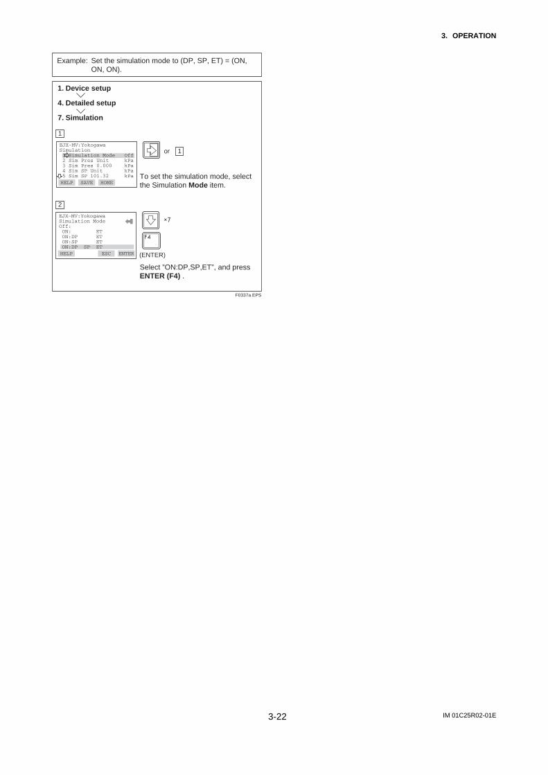
3. OPERATION
F0337a.EPS
(ENTER)
EJX-MV:YokogawaSimulation 1 Simulation Mode Off 2 Sim Pres Unit kPa 3 Sim Pres 0.000 kPa 4 Sim SP Unit kPa 5 Sim SP 101.32 kPa
HOMETo set the simulation mode, select the Simulation Mode item.
1. Device setup
4. Detailed setup
7. Simulation
Example: Set the simulation mode to (DP, SP, ET) = (ON, ON, ON).
EJX-MV:YokogawaSimulation ModeOff: ON: ET ON:DP ET ON:SP ET ON:DP SP ETHELP ESC
Select ”ON:DP,SP,ET”, and press ENTER (F4) .
2
1
HELP SAVE
1or
ENTER
×7

IM 01C25R02-01E3-23
3. OPERATION
Example: Setting of simulation condition: DP = 5kPa, SP = 5MPa, ET = 98degC.
1
F0332a.EPS
EJX-MV:YOKOGAWASimulation 1 Simulation Mode ON 2 Sim Pres Unit kPa 3 Sim Pres 0.000 kPa 4 Sim SP Unit kPa 5 Sim SP 101.32 kPaHELP SET HOME OK
EJX-MV:YOKOGAWASim Pres UnitPa kPa torr atm Mpa
DEL SET ESC ENTER
2
Select kPa and press ENTER (F4) .
EJX-MV:YOKOGAWASimulation 1 Simulation Mode 2 Sim Pres Unit kPa 3 Sim Pres 0.000 kPa 4 Sim SP Unit kPa 5 Sim SP 101.32 kPaHELP DEL HOME
3
To set differential pressure value for simulation, select the Sim Pres item.
EJX-MV:YOKOGAWASim Pres 0.000kPa 5
ESC
4
Set ’5’and press ENTER (F4).
To set differential pressure unit for simulation, select the Sim Pres Unit item.
DEL ENTER
(ENTER)
(ENTER)
‘5’
EJX-MV:YOKOGAWASimulation 1 Simulation ON 2 Sim Pres Unit kPa 3 Sim Pres 0.000 kPa 4 Sim SP Unit kPa 5 Sim SP 101.32 kPa
HOME
5
To set static pressure unit for simulation, select the Sim SP Unit item.SAVE
6
Select MPa and press ENTER (F4).
EJX-MV:YOKOGAWASimulation 1 Simulation ON 2 Sim Pres Unit kPa 3 Sim Pres 0.000 kPa 4 Sim SP Unit kPa 5 Sim SP 101.32 kPa
DEL SET HOME
7
To set static pressure value for simulation, select the Sim SP item.
1. Device setup
4. Detailed setup
7. Simulation
2or
3or
4or
5or
HELP
HELP SAVE
HELP
HELP
EJX-MV:YOKOGAWASim SP UnitPa kPa torr atm Mpa
DEL SET ESC ENTER
(ENTER)
HELP
HELP SAVE
F0333a.EPS
EJX-MV:YOKOGAWASim Pres 101.32kPa 5
ESC
8
Set ’5’and press ENTER (F4).DEL ENTER
(ENTER)
‘5’
EJX-MV:YOKOGAWASimulation 2 Sim Pres Unit kPa 3 Sim Pres 0.000 kPa 4 Sim SP Unit kPa 5 Sim SP 101.32 kPa 6 Sim Temp Unit
HOME
9
To set external temperature unit for simulation, select the Sim ET Unit item.
10
Select degC and press ENTER (F4) .
EJX-MV:YOKOGAWASim temp UnitKelvin degC degF Kelvin
HELP SET ESC ENTER
EJX-MV:YOKOGAWASimulation 3 Sim Pres 0.000 kPa 4 Sim SP Unit kPa 5 Sim SP 101.32 kPa 6 Sim Temp Unit degC 7 Sim Temp
HELP SAVE HOME
11
EJX-MV:YOKOGAWASim Temp 273.15kelvin 98
12
EJX-MV:YOKOGAWASimulation 3 Sim Pres 0.000 kPa 4 Sim SP Unit kPa 5 Sim SP 101.32 kPa 6 Sim Temp Unit degC 7 Sim TempHELP HOME
13
To set external temperature value for simulation, select the Sim ET item.
SEND
(ENTER)
Set ’98’and press ENTER (F4).
HELP
ESCDEL ENTERHELP
6or
7or
HELP SAVE
HELP
(ENTER)
‘98’
Press SEND (F2) to send the changed data to the transmitter. Check that disappears.SEND
(SEND)

IM 01C25R02-01E3-24
3. OPERATION
3.5.10 Basic Flow Calculation
Some parameters are set with the manual. The flowrate calculate by constant flow factor.This is called ”Basic mode.”
F0337b.EPS
(ENTER)
EJX-MV:YokogawaBasic Flow Calc 1 Flow Calc Mode 2 Fluid Type 3 Flow Calc Fixed 4 Ref Sp 5 Ref Temp
HOMETo enable Basic mode, select the Flow Calc Mode item.
1. Device setup
4. Detailed setup
8. Basic Flow Calc
Example: Enable Basic mode.
EJX-MV:YokogawaFlow Calc ModeAuto Comp. Mode Auto Comp. Mode Basic Mode
ESCSelect Basic Mode, and press ENTER (F4) .
2
1
HELP SAVE
ENTER
To release Basic mode, set Flow Calc Mode to AutoComp. Mode.To set other parameters of Basic mode on Table 3.2.
Table3.2 Basic Flow Calc Set-up Steps
T0310.EPS
Parameter Contents
Flow Calc Mode Select Basic Mode
Fluid Type Select liquid or gas
Flow Calc Fiexed
Step
1
2
Ref SP Input reference static pressure
Ref Temp Input reference temperature
4
5
Temp K1Input the density rate of change per temperature 1degC.6
3 Input Kfactor
Remarks
This factor is used for gas.When fluid type is liquid, set 0 to Ref SP(Spb).
This factor is used for liquid.When fluid type is gas, set 0 to TempK1. Refer to Table 3.4 Symbol
Kfactor calculated by Table 3.3 Flow Equation and Kfactor Calculation
Flow calculation for Basic flow EquationThe flow equation select by fluid type and flow unit category.
Table 3.3 Flow Equation and Kfactor Calculation
T0311.EPS
Mass Flow
Normal-StandardVolume Flow
Volume Flow
Mass Flow
Normal-StandardVolume Flow
Volume Flow
Kfactor = π /4 " Nc " C / 1- ß4 " # " d2
" 2 " b
Qm or Qv or Qv_norm
= Kfactor " ∆ " (1+ Temp K1 " (T-Tb))
Fluid Type Flow unit category Kfactor *2 Flow Equation
liquid
Gas
Kfactor = π /4 " Nc " C / 1- ß4 " # " d2
" 2 " b / norm
Kfactor = π /4 " Nc " C / 1- ß4 " # " d2
" 2 / b
Kfactor = π /4 " Nc " C / 1- ß4 " # " d2
" 2 " b " 1/K
Kfactor = π /4 " Nc " C / 1- ß4 " # " d2
" 2 " b " 1/K / norm
Kfactor = π /4 " Nc " C / 1- ß4 " # " d2
" 2 / (b " 1/K)
*1
Qm or Qv or Qv_norm
= Kfactor" ∆ " Tb/T" SP/SPb
= Kfactor" ∆ " T/Tb" SPb/SP
*1
*1
*1 mark indicate user input.
*2 Kfactor must be calculated refer to the Table 6 Flow unit category.
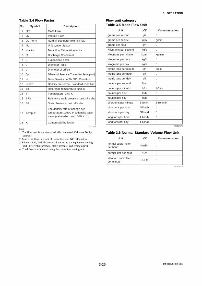
IM 01C25R02-01E3-25
3. OPERATION
Table 3.4 Flow Factor
T0312.EPS
Symbol Description
Qm Mass Flow
Qv Volume Flow
No
1
2
Qv_norm Normal-Standard Volume Flow
Nc Unit convert factor
3
4
Kfactor Basic flow Calcuration factor
C Discharge Coefficient
5
6
# Expansion Factor
$ Diameter Ratio
7
8
d Diameter of orifice
∆p Differential Pressure (Transmitter Setting unit)
9
10
b Base Density on Tb, SPb Condition
norm Density on Normal, Standard condition
11
12
Tb Reference temperature unit: K
T Temperature unit: K
13
14
SPb Reference static pressure unit: kPa abs
SP Static Pressure unit: kPa abs
15
16
Temp K1
The density rate of change per temperature 1degC of a density base value (value which set 100% to 1)
17
K Compressibility factor18
Note1. The flow unit is not aoutomatically converted. Calculate Nc by
yourself.2. Match the flow rate unit of transmitter and NC calculation.3. Kfactor, SPb, and Tb are calculated using the equipment setting
unit (differential pressure, static pressure, and temperature).4. Total flow is calculated using the transmitter setting unit.
Flow unit categoryTable 3.5 Mass Flow Unit
T0315.EPS
LCD Communication
g/s ←
g/m g/min
Unit
grams per second
grams per minute
g/h ←
kg/s ←
grams per hour
Kilograms per second
kg/m kg/min
kg/h ←
kilograms per minute
kilograms per hour
kg/d ←
t/h ←
kilograms per day
t/m t/minmetric tons per minute
metric tons per hour
t/d ←
lb/s ←
metric tons per day
pounds per second
lb/m lb/min
lb/h ←
pounds per minute
pounds per hour
lb/d ←
STon/m STon/min
pounds per day
short tons per minute
STon/h ←
STon/d ←
short tons per hour
short tons per day
LTon/h ←
LTon/d ←
long tons per hour
long tons per day
Table 3.6 Normal Standard Volume Flow Unit
T0316.EPS
Communication
←
←
←
LCD
Nm3/h
NL/h
SCFM
Unit
normal cubic meter per hour
normal liter per hour
standard cubic feet per minute

IM 01C25R02-01E3-26
3. OPERATION
Table 3.7 Volume Flow Unit
T0317.EPS
LCD Communication
CFM ←
GPM ←
Unit
cubic feet per minute
gallons per minute
L/m L/min
IGal/m ImpGal/min
liters per minute
imperial gallons per minute
m3/h ←
gal/s ←
cubic meter per hour
gallons per second
L/s ←
Mgal/d ←million gallons per day (FF:mega)
ML/d ←million liters per day (FF:mega)
liters per second
CFS ←
ft3/d ←
cubic feet per second
cubic feet per day
m3/s ←
m3/d ←
cubic meters per second
cubic meters per day
IGal/h ImpGal/h
IGal/d ImpGal/d
imperial gallons per hour
imperial gallons per day
CFH ←
m3/m m3/min
cubic feet per hour
cubic meters per minute
bbl/s ←
bbl/m bbl/min
barrels per second
barrels per minute
bbl/h ←
bbl/d ←
barrels per hour
barrels per day
gal/h ←
IGal/s ImpGal/s
gallons per hour
imperial gallons per second
L/h ←
gal/d ←
liters per hour
gallons per day
3.5.11 Software Write Protection
EJX configured data is saved by using a write protec-tion function. The write protection status is set to”Yes” when 8 alphanumeric characters are entered inthe New password field and transferred to thetransmitter.
When write protection is set to ”Yes,” the transmitterdoes not accept parameter changes. When the sameeight alphanumeric string entered in the New pass-word field is also entered in the Enable wrt 10minfield and transferred to the transmitter, it will bepossible to change transmitter parameters during a 10minute period.
To change the transmitter from the write protection”Yes” status back to Write protection ”No” status, useEnable wrt 10min to first release the write protectionfunction and then enter eight spaces in the Newpassword field.

IM 01C25R02-01E3-27
3. OPERATION
(1) Setting Password
F0338.EPS
(ENTER)
(DEL)
EJX-MV:Hot key 1 keypad input 2 Wrt protect menu
HELP SEND ESC ENTERPress Hot key.Select Wrt protect menu.
Set 1 2 3 4 and press ENTER (F4).
EJX-MV:Enter new password to change state of writeprotect: 1234
HELP DEL ABORT ENTER
(ENTER)
EJX-MV:Re-enter new passwordwithing 30 seconds: 1234 1234
HELP DEL ABORT ENTER
Example: Set the password to 1 2 3 4 .
×4
×2
Set the new password again, and press ENTER (F4).
EJX-MV:Wrt protect menu 1 Write Protect No 2 Enable wrt 10min 3 New password 4 Software seal Keep
HELP SEND ESC ENTER
Select New password.
2
3
4
1
(OK)
Press OK (F4).Write Protect status changes from NO to YES.
EJX-MV:It changed the stateof protection relatedpassword.
HELP DEL ABORT OK
5
(2) Entering Password to Enablethe Parameter Changes
F0339.EPS
(ENTER)
(DEL)
EJX-MV:Hot key 1 keypad input 2 Wrt protect menu
HELP SEND ESC ENTERPress Hot key.Select Wrt protect menu.
Set 1 2 3 4 and press ENTER (F4).
EJX-MV:Enter currentpassword to enable towrite for 10minutes: 1234HELP DEL ABORT ENTER
(OK)
EJX-MV:Released the writeprotection for 10minutes.
HELP DEL ABORT OK
(OK)
Press OK (F4), and the write protect is released for 10 minutes.
EJX-MV:If you wish to release completely,you have to changepassword to all of spaces.
HELP DEL ABORT OK
Example: Enter the password of 1 2 3 4 .
×4
Press ENTER (F4).
EJX-MV:Wrt protect menu 1 Write Protect No 2 Enable wrt 10min 3 New password 4 Software seal Keep
HELP SEND ESC ENTER
Select Enable wrt 10min.
2
3
4
5
1
(3) Releasing PasswordTo release the password completely, enter spaces in theNew password field while the write protect functionis released.
(4) Software SealWhen you lose the password that has been registered, itis possible to release the Write Protect mode byusing the general use password: “YOKOGAWA.”When the password is used, the status shown in theparameter of Software seal is changed from “KEEP”to “BREAK.” The status returns to “KEEP” byentering a newly set password at Enable wrt 10min.

IM 01C25R02-01E3-28
3. OPERATION
3.5.12 Alarm
The function is used to display the alarm codes whenthe input differential pressure exceeds the specifiedvalue within the calibration range. The same is avail-able for the input static pressure and the externaltemperature on the pressure sensor. Refer to table 4.1Alarm Message Summary for the specific alarm codeto be generated.
F0346.EPS
(ENTER)
EJX-MV:Pres Alert ModeOff Off Hi Al Detect Lo Al Detect Hi/Lo Al DetectHELP DEL ESC ENTER Select Hi AL Detect, and press
ENTER (F4).
1. Device setup
4. Detailed setup
3. Output condition
4. Process Alerts
1. Pres Alert
1. Pres Alert Mode
Example: Set the alert mode from OFF to Hi. Al Detect for the input pressure.
1
2
EJX-MV:Pres Alert 1 Alert Mode 2 Pres Hi Alert 3 Pres Lo Alert
HELP SEND HOME
(SEND)
Press SEND (F2) to send the data to the transmitter, then check to confirm that disappears.SEND
F0347.EPS
Example: Set the higher alert value of 75 for alarm generation.
(ENTER)
Pres Hi Alert Val 100.000 kPa 75.000
HELP DEL ESC ENTER Enter 75, and press ENTER (F4).
1. Device setup
4. Detailed setup
3. Output condition
4. Process Alerts
1. Pres Alert
2. Pres Hi Alert1
2
Pres Alert 1 Alert Mode 2 Pres Hi Alert 3 Pres Lo Alert
HELP SEND HOME
(SEND)
Press SEND (F2) to send the data to the transmitter, then check to confirm that disappears.SEND
‘75’
3.5.13 Status Output
This feature is used for a transistor output (opencollector) of an on/off signal according to the status ofhigh and low alarm limits, which are user-configurablevalues as shown in 3.5.12 Alarm. The status output canbe assigned as any combination of the high or lowlimits of the input pressure, input static pressure,external temperature, or flow.
NOTE
No status output signal has been defined for aCPU failure or hardware error. Use a 4-20 mAsignal to indicate a transmitter’s failure.
F0349.EPS
EJX-MV:DO SelectOff Off Pres SP Temp
ESC ENTER
1. Device setup
4. Detailed setup
3. Output condition
4. Process Alerts
5. DO Config
2. DO Select and 3. DO Signal type
Example: Set the status output to output an off signal when the input pressure exceeds 75 kPa with the alert mode of Hi. Al Detect.
EJX-MV:DO Config 1 Digital Output Off 2 DO Select Pres 3 DO Signal type 4 DO Test 5 Do FrequencyHELP SEND HOME ENTER
Press SEND (F2) to send the data to the transmitter, then check to confirm that disappears.
(SEND)
SEND
1
2
EJX-MV:DO Config 1 Digital Output Off 2 DO Select Pres 3 DO Signal type 4 DO Test 5 Do FrequencyHELP SEND HOME ENTER
Press SEND (F2) to send the data to the transmitter, then check to confirm that disappears.
(SEND)
SEND
4
(ENTER)
Select Pres, and press ENTER (F4).
EJX-MV:DO Signal typeON WHEN AL. DETECT ON When Al. Detect OFF When Al. Detect Scaled Pulse Frequency
ESC ENTER
3
(ENTER)
Select OFF WHEN AL. DETECT, and press ENTER (F4).

IM 01C25R02-01E3-29
3. OPERATION
Status output for higher alert value
Status output for lower alert value
F0350.EPS
Output(%)
Status output
Status output
Time (t)
Time (t)
Settingvalue
Settingvalue
5% of hysteresis
Output(%)
5% of hysteresis
On Off
Example: Status output operation of ON WHEN AL. DETECT
On
On
On
Off
(1) Status output (contact output)The status signal is output by Pres, SP, ET or Flow.The HI/LO alarm is output by the pulse terminal.
(2) DO Signal typeThe output from a pulse terminal is chosen from thefllowing.
T0318.EPS
Item Contents
Status Output
Digital Output: On When Al. Detect (Status Low)
Digital Output: OFF When Al. Detect (Status High)
Pulse Output
Scaled Pulse
Frequency
(3) Digital OutputAlarm output ON/OFF is displayed.(Effective, when On When AI Detect or Off When AIDetect is chosen by DO Signal type)
(4) DO SelectThe process values that are output as an status alarmare given in the following table.
T0319.EPS
Contents
-
DP
SP
ET
Display Item
Off
Press
SP
Temp
DP/SP
DP/ET
SP/ET
DP/SP/ET
Flow
Press/SP
Press/Temp
SP/Temp
Press/SP/Temp
DP/Flow
SP/Flow
ET/Flow
DP/ET/Flow
Flow
Press/Flow
SP/Flow
Temp/Flow
DP/ET/Flow
SP/ET/Flow
DP/SP/ET/Flow
Press/SP/Flow
Press/Temp/Flow
SP/Temp/Flow
Press/SP/Temp/Flow
3.5.14 Pulse Output
As both the contact output and the pulse output use thesame terminal, either may be used.Pulse Output process value: Flow
The pulse output is selected from the following twokinds by the mode.
(1) Scaled pulse A single pulse is output for a specified flow amount.
(2) Frequency outputThe flow rate is determined from the number ofpulses output each second in which it is made to begoing to output in one second at 100% flowingquantity.
Max. frequency : 10kHzDuty cycle : Approx 50%
Example of Pulse Output
F0350a.EPS
T = 1sec
The number of pulses (PPS)
(*1) Example of scaled pulse Pulse Rate =10kg
(*2) Example of freqency output Configuration: Freq at 100% =10000Hz Flow Rate: URL =100% 10000(PPS)

IM 01C25R02-01E3-30
3. OPERATION
(1) Scale pulse
Example: Scaled Pulse 10 kg Set
Setting of Total Flow Units
Press SEND (F2)
F0354.EPS
1
EJX-MV:Total Flow Unit g g kg t Ib
ESC ENTERSelect kg, and press ENTER (F4)
(ENTER)
2
EJX-MV:Total Flow Unit 1 Total flow 0 kg 2 Total Flow Unit kg 3 Pulse rate 10 4 Freq at 100% 5 Total Flow ModeHELP HOMESEND
(SEND)
1. Device setup
4. Detailed setup
2. Signal condition
5. Total Flow
2. Total Flow Unit
HELP
Setting of Pulese rate
Press SEND (F2)
F0355.EPS
1
EJX-MV:Pulse rate
1200
10
ESCDEL ENTERSet 10 and press ENTER (F4)
(ENTER)
2
HELP HOMESEND
(SEND)
(ENTER)
1. Device setup
4. Detailed setup
2. Signal condition
5. Total Flow
3. Pulse rate
HELP
EJX-MV:Total Flow Unit 1 Total flow 0 kg 2 Total Flow Unit kg 3 Pulse rate 10 4 Freq at 100% 5 Total Flow Mode
Set Scaled Pulse
F0358.EPS
(ENTER)
EJX-MV:YokogawaDo signal typeScaled Pulse On when Al. Detect Off when Al. Detect Scaled Pulse Frequency
ESC ENTERSelect Scaled Pulse, and press ENTER (F4).
1. Device setup
4. Detailed setup
3. Output condition
4. Process Alerts
5. DO Config
3. DO Signal Type
EJX-MV:YokogawaDo Confing 1 Digital Output Off 2 DO Select Flow 3 DO Signal Type 4 DO Test 5 DO Frequency 0HzHELP SEND HOME ENTER Press SEND (F2)
(SEND)
1
2
(2) Frequency output
Example: Freq at 100% is 1000 Hz Set
Setting of Freq at 100%
Press SEND (F2)
F0357.EPS
1
EJX-MV:Freq at 100%
1200 Hz
1000
ESCDEL ENTERSet 1000 and press ENTER (F4)
(ENTER)
(ENTER)2
HELP HOMESEND
(SEND)
1. Device setup
4. Detailed setup
2. Signal condition
5. Total Flow
4. Freq at 100%
HELP
EJX-MV:Total Flow Unit 1 Total flow 0 kg 2 Total Flow Unit kg 3 Pulse rate 10 4 Freq at 100% 5 Total Flow Mode

IM 01C25R02-01E3-31
3. OPERATION
Set Frequency
F0351.EPS
(ENTER)
EJX-MV:YokogawaDo signal typeScaled Pulse On when Al. Detect Off when Al. Detect Scaled Pulse Frequency
ESC ENTERSelect Frequency, and press ENTER (F4).
1. Device setup
4. Detailed setup
3. Output condition
2. Process Alerts
5. DO Config
3. DO Signal Type
EJX-MV:YokogawaDo Confing 1 Digital Output Off 2 DO Select Flow 3 DO Signal Type 4 DO Test 5 DO Frequency 0HzHELP SEND HOME ENTER Press SEND (F2)
(SEND)
1
2
3.5.15 DO Test
Contact and pulse output testThe following table gives information on the contactand pulse output test.
This test function is canceled if no operations areperformed for about 10 minutes.
T0320.EPS
Item
Status High
Status Low
Frequency
Exit
Contents
Contact Output: OFF
Contact Output: ON
Frequency Range 0-10000Hz
Contact and a pulse output test are canceled
Set ’1000’and press ENTER (F4).
Example: Frequency 1000Hz Set
F0352.EPS
1
EJX-MV:YokogawaDO Test 1 Status High 2 Status Low 3 Frequency 4 Exit
ABORT ENTERSelect Scaled Pulse, and press ENTER (F4).
(ENTER)
2
EJX-MV:YokogawaFrequency 1000
HELP ABORTDEL ENTER
(ENTER)
(OK)
‘1000’
3
EJX-MV:YokogawaDigital Output isFixed to on;Frequency is 1000 Hz
ABORT OK Press OK (F4) .
1. Device setup
4. Detailed setup
3. Output condition
4. Process Alerts
5. DO Config
4. DO Test

IM 01C25R02-01E3-32
3. OPERATION
3.6 Diag/Service3.6.1 Test OutputThis feature can be used to output a fixed current forloop checks. The available range for test outputdepends on the settings for the AO lower limit andAO upper limit parameters, whose limit is from 3.8mA (-1.25%) to 21.6 mA (110%) .
1
F0325.EPS
Set the control loop in manual mode, and press OK (F4).
EJX-MV:YOKOGAWAWARN-loop should beremoved fromautomatic control
DEL SET ABORT OK
EJX-MV:YOKOGAWAChoose analog outputlevel 1 4mA 2 20mA 3 Other 4 End
DEL SET ABORT ENTER
2
Select Other, and press ENTER (F4).Supplementary explanation.1. 4 mA: Outputs a 4 mA current signal2. 20 mA: Outputs a 20 mA current signal3. Other: Sets a desired output using the
alphanumeric keys4. End: Exits
EJX-MV:YOKOGAWAOutput
12
HELP DEL ABORT ENTER
3
Enter 12, and press ENTER (F4).A fixed current of 12 mA is output.
EJX-MV:YOKOGAWAFld dev output isfixed at 12.000 mA
DEL ABORT
4
Press OK (F4).HELP SEND OK
×2
(ENTER)
×3
(ENTER)
(ENTER)
(OK)
(OK)
‘1 2’
(OK)
EJX-MV:YOKOGAWAChoose analog output level 1 4mA 2 20mA 3 Other 4 EndDEL ABORT
5
To finish the loop test, select End, and press ENTER (F4).
HELP SEND ENTER
EJX-MV:YOKOGAWANOTE-loop may bereturned to automaticcontrol
DEL ESC
6
Press OK (F4).HELP SEND OK
Example: To output 12 mA (50%)
1. Device setup
2. Diag/Service
2. Test
1. Loop test
CAUTION
Test output continues for approximately 10minutes, then is released automatically. Even ifthe HART communicator power supply is turnedoff or the communication cable is disconnected,test output will continue for approximately 10minutes.
3.6.2 Sensor Trim
Each DPharp EJX series transmitter is factory charac-terized. Factory characterization is the process ofcomparing a known pressure input with the output ofeach transmitter sensor module over the entire pressureand temperature operating range. During the character-ization process, this comparison information is storedin the transmitter EEPROM. In operation, the transmit-ter uses this factory-stored curve to produce a processvariable output (PV), in engineering units, dependenton the pressure input.
The sensor trim procedure allows you to adjust forlocal conditions, changing how the transmitter calcu-lates process variables. There are two ways to trim thesensor: a zero trim and a full sensor trim. A zero trimis a one-point adjustment typically used to compensatefor mounting position effects or zero shifts caused bystatic pressure. A full sensor trim is a two-pointprocess, in which two accurate end-point pressures areapplied (equal to or greater than the range values), andall output is linearized between them.
Full Sensor Trim—Auto Trim and Manual TrimFull sensor trim is carried out by performing Auto,Lower Pt followed by Auto, Upper Pt.
Also, you can manually perform the trimming proce-dure with Manual, Lower Pt and Manual, UpperPt .
The full sensor trim is a two-point adjustment, and thelower point adjustment should always be performedbefore the upper point adjustment in order to maintainthe pitch between the zero and 100% points within thecalibration range.
In the manual method, the reference pressure shouldalso be applied to the transmitter at both the lower andupper points. Without the reference pressure, Manual,Lower Pt and Manual, Upper Pt may not representthe correct value for each adjustment point.
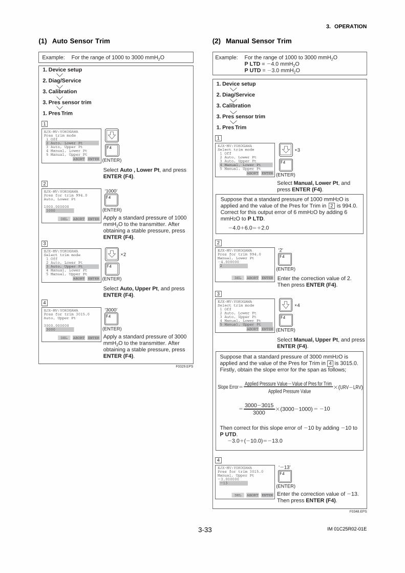
IM 01C25R02-01E3-33
3. OPERATION
(1) Auto Sensor Trim
Apply a standard pressure of 1000 mmH2O to the transmitter. After obtaining a stable pressure, press ENTER (F4).
Example: For the range of 1000 to 3000 mmH2O
F0329.EPS
1
EJX-MV:YOKOGAWAPres trim mode 1 Off 2 Auto, Lower Pt 3 Auto, Upper Pt 4 Manual, Lower Pt 5 Manual, Upper Pt
ABORT ENTER
Select Auto , Lower Pt, and press ENTER (F4).
(ENTER)
2
EJX-MV:YOKOGAWAPres for trim 994.0Auto, Lower Pt
1000.000000 1000
ABORTDEL ENTER
(ENTER)
‘1000’
Apply a standard pressure of 3000 mmH2O to the transmitter. After obtaining a stable pressure, press ENTER (F4).
3
EJX-MV:YOKOGAWASelect trim mode 1 Off 2 Auto, Lower Pt 3 Auto, Upper Pt 4 Manual, Lower Pt 5 Manual, Upper Pt
ABORT ENTER
Select Auto, Upper Pt, and press ENTER (F4).
(ENTER)
4
EJX-MV:YOKOGAWAPres for trim 3015.0Auto, Upper Pt
3000.000000 3000
ABORTDEL ENTER
(ENTER)
‘3000’
1. Device setup
2. Diag/Service
3. Calibration
3. Pres sensor trim
1. Pres Trim
×2
(2) Manual Sensor Trim
Suppose that a standard pressure of 1000 mmH2O is applied and the value of the Pres for Trim in is 994.0. Correct for this output error of 6 mmH2O by adding 6 mmH2O to P LTD.
4.0%6.0&%2.0
Enter the correction value of 2. Then press ENTER (F4).
Suppose that a standard pressure of 3000 mmH2O is applied and the value of the Pres for Trim in is 3015.0. Firstly, obtain the slope error for the span as follows;
Then correct for this slope error of 10 by adding 10 to P UTD. 3.0%(10.0)&13.0
F0348.EPS
1
EJX-MV:YOKOGAWASelect trim mode 1 Off 2 Auto, Lower Pt 3 Auto, Upper Pt 4 Manual, Lower Pt 5 Manual, Upper Pt
ABORT ENTER
Select Manual, Lower Pt, and press ENTER (F4).
(ENTER)
2
2
EJX-MV:YOKOGAWAPres for trim 994.0Manual, Lower Pt4.000000 2
ABORTDEL ENTER
(ENTER)
‘2’
Enter the correction value of 13. Then press ENTER (F4).
3
EJX-MV:YOKOGAWASelect trim mode 1 Off 2 Auto, Lower Pt 3 Auto, Upper Pt 4 Manual, Lower Pt 5 Manual, Upper Pt
ABORT ENTER
Select Manual, Upper Pt, and press ENTER (F4).
(ENTER)
4
4
EJX-MV:YOKOGAWAPres for trim 3015.0Manual, Upper Pt3.000000 13
ABORTDEL ENTER
(ENTER)
‘13’
1. Device setup
2. Diag/Service
3. Calibration
3. Pres sensor trim
1. Pres Trim
Example: For the range of 1000 to 3000 mmH2O P LTD = 4.0 mmH2O P UTD = 3.0 mmH2O
Applied Pressure ValueValue of Pres for TrimApplied Pressure Value
Slope Error "(URVLRV)&
300030153000
"(30001000)& & 10
×3
×4

IM 01C25R02-01E3-34
3. OPERATION
(3) Sensor Trim for Static Pressure or Exter-nal Temperature
For the EJX multivariable transmitter, full sensor trimof the static pressure or external temperature isperformed in the same way as with the differentialpressure.
(4) Reset Trim Adjustment to Factory SettingThe Clear P trim, Clear SP trim and Clear ETtrim commands can reset the trim adjustment to theinitial calibrated values that were set. The amount ofthe adjustment performed with the external zero-adjustment screw is returned to the initial setting aswell.
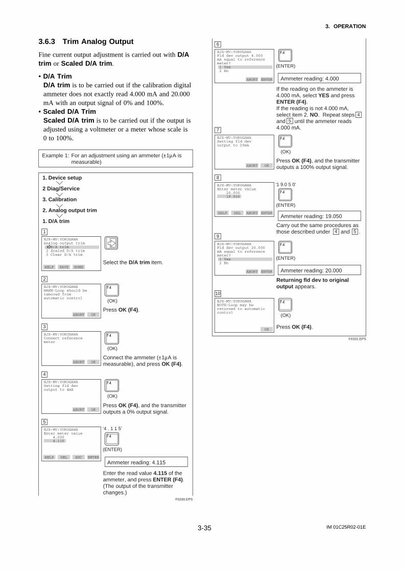
IM 01C25R02-01E3-35
3. OPERATION
3.6.3 Trim Analog Output
Fine current output adjustment is carried out with D/Atrim or Scaled D/A trim.
• D/A TrimD/A trim is to be carried out if the calibration digitalammeter does not exactly read 4.000 mA and 20.000mA with an output signal of 0% and 100%.
• Scaled D/A TrimScaled D/A trim is to be carried out if the output isadjusted using a voltmeter or a meter whose scale is0 to 100%.
1
F0330.EPS
Select the D/A trim item.
EJX-MV:YOKOGAWAAnalog output trim 1 D/A trim 2 Scaled D/A trim 3 Clear D/A trim
HELP SAVE HOME OK
EJX-MV:YOKOGAWAWARN-Loop should beremoved fromautomatic control
DEL SET ABORT OK
2
Press OK (F4).
EJX-MV:YOKOGAWAConnect referencemeter
HELP DEL ABORT OK
3
Connect the ammeter (±1µA is measurable), and press OK (F4).
EJX-MV:YOKOGAWASetting fld devoutput to 4mA
HELP ABORT
4
Press OK (F4), and the transmitter outputs a 0% output signal.DEL OK
(OK)
(OK)
(OK)
EJX-MV:YOKOGAWAEnter meter value 4.000 4.115
HELP ESC
5
Enter the read value 4.115 of the ammeter, and press ENTER (F4).(The output of the transmitter changes.)
DEL ENTER
(ENTER)
‘4 . 1 1 5’
Example 1: For an adjustment using an ammeter (±1µA is measurable)
1. Device setup
2 Diag/Service
3. Calibration
2. Analog output trim
1. D/A trim
Ammeter reading: 4.115
6
F0331.EPS
If the reading on the ammeter is 4.000 mA, select YES and press ENTER (F4).If the reading is not 4.000 mA, select item 2. NO. Repeat steps and until the ammeter reads 4.000 mA.
EJX-MV:YOKOGAWAFld dev output 4.000mA equal to referencemeter? 1 Yes 2 No
HELP SET ABORT ENTER
EJX-MV:YOKOGAWASetting fld devoutput to 20mA
DEL SET ABORT OK
7
4
4
5
5
Press OK (F4), and the transmitter outputs a 100% output signal.
EJX-MV:YOKOGAWAEnter meter value 20.000 19.050
HELP DEL ABORT ENTER
8
Carry out the same procedures as those described under and .
EJX-MV:YOKOGAWAFld dev output 20.000mA equal to referencemeter? 1 Yes 2 No
HELP ABORT
9
Returning fld dev to original output appears.
DEL ENTER
(OK)
(ENTER)
(ENTER)
‘1 9.0 5 0‘
EJX-MV:YOKOGAWANOTE-Loop may bereturned to automaticcontrol
HELP ESC
10
Press OK (F4).DEL OK
(OK)
(ENTER)
Ammeter reading: 19.050
Ammeter reading: 20.000
Ammeter reading: 4.000

IM 01C25R02-01E3-36
3. OPERATION
1
F0332.EPS
Select the Scaled D/A trim item.
EJX-MV:YOKOGAWAAnalog output trim 1 D/A trim 2 Scaled D/A trim 3 Clear D/A trim
HELP SET HOME OK
EJX-MV:YOKOGAWAWARN-Loop should beremoved fromautomatic control
DEL SET ABORT OK
2
Press OK (F4).
EJX-MV:YOKOGAWATrim will be scaledfrom 4.000 to 20.000 1 Proceed 2 Change
HELP DEL ABORT ENTER
3
Select Change, and press ENTER (F4).When item 3. Proceed is selected, D/A trim must be carried out.
EJX-MV:YOKOGAWASet scale- Lo outputvalue4.000000 1
HELP ABORT
4
Enter the value read on the meter when the signal is 4 mA. In this case, Enter the value of the voltage across a 250 Ω resistor (1 V), and press ENTER (F4).
DEL ENTER
(OK)
(ENTER)
‘1’
EJX-MV:YOKOGAWASet scale- Hi outputvalue20.000000 5
HELP ABORT
5
Enter the value read on the meter when the signal is 20 mA. Then, enter 5, and press ENTER (F4).
DEL ENTER
(ENTER)
‘5’
Example 2: To adjust using a voltmeter
6
Select Proceed and press ENTER (F4).
EJX-MV:YOKOGAWATrim will be scaledfrom 1.000 to 5.000 1 Proceed 2 Change
HELP SET ABORT ENTER
EJX-MV:YOKOGAWAConnect referencemeter
DEL SET ABORT OK
7
Connect the voltmeter, and press OK (F4).
EJX-MV:YOKOGAWASetting fld dev output to 4mA
HELP DEL ABORT OK
8
Press OK (F4). A 0% output signal is output.
(OK)
(OK)
(ENTER)
1. Device setup
2 Diag/Service
3. Calibration
2. Analog output trim
2. Scaled D/A trim
F0333.EPS
EJX-MV:YOKOGAWAEnter meter value1.000000 1.010
HELP ABORT
9
98
Enter the reading of the voltmeter (1.010), and press ENTER (F4).(The output of the transmitter changes.)
DEL ENTER
(ENTER)
(ENTER)
‘1 . 0 1’
EJX-MV:YOKOGAWAScaled output: 1.000equal readoutdevice? 1 Yes 2 No
HELP ABORT
10
DEL ENTER
Voltmeter reading: 1.010
If the reading on the voltmeter is 1.000, select Yes and press ENTER (F4).If the reading is not 1.000, select No. Repeat steps and until the voltmeter reads 1.000 V.
Voltmeter reading: 1.000
11
Press OK (F4). A 100% output signal is output.
EJX-MV:YOKOGAWASetting fld devoutput to 20mA
HELP SET ABORT OK
EJX-MV:YOKOGAWAEnter meter value5.000000 5.210
HELP DEL ABORT ENTER
12
EJX-MV:YOKOGAWAScaled output: 5.000equal readoutdevice? 1 Yes 2 No
HELP DEL ABORT ENTER
13
EJX-MV:YOKOGAWANOTE-Loop may bereturned to automaticcontrol
HELP ABORT
14
Enter the reading of the voltmeter (5.210), and press ENTER (F4).
DEL OK
(ENTER)
“Returning fid dev to original output”
(OK)
(ENTER)
‘5 . 2 1’
(OK)
Voltmeter reading: 5.210
Select Yes and press ENTER (F4).
Press OK (F4).
Voltmeter reading: 5.000

IM 01C25R02-01E4-1
4. SELF-DIAGNOSTICS
4. SELF-DIAGNOSTICS
4.1 Self-Diagnostics
4.1.1 Identify Problems by Using theCommunicator
The HART communicator can be used to run self-diagnostics on a transmitter and check for incorrectdata settings.
The Self test and Status commands are available forself-diagnostics. When Self test is run, the integralindicator shows an error code and alarm message if thetransmitter detects any illegal parameter settings orfunctional faults. See table 4.1 Alarm Message Sum-mary for probable causes and countermeasures. If thespecific diagnostic item is known for the check, youcan directly call up the item by using the Statuscommand. See table 4.1 to determine the status group.
The HART communicator diagnoses every commandyou make. When a faulty command or keypad input isperformed, an error message appears. See table 4.2HART Commnicator Error Messages for the details.
Diagnostic by “self test”
1
F0401.EPS
Call up Test, and select Self test.
EJX-MV:Test 1 Loop Test 2 Self test 3 Master test
HELP SAVE HOME OK
EJX-MV:Self test OK
DEL SET ABORT OK
2
If no error is detected, Self test OK is displayed.If there is an error, an error message appears.
1. Device setup
2. Diag/Service
2. Test
2. Self test
Diagnostic by “status”
1
F0402EPS
Call up Status, and select Status group 6.
EJX-MV:Status 2 Status group 2 3 Status group 3 4 Status group 4 5 Status group 5 6 Status group 6HELP SAVE HOME OK
EJX-MV:Status group 6 Illegal P LRV On Illegal P URV Off Illegal P SPAN Off P SPAN trim err Off P ZERO trim err Off
DEL SET ABORT EXIT
2
If there is no error, the result of diagnostics is indicated as Off. If On is indicated, a countermeasure for that error is necessary.
1. Device setup
2. Diag/Service
1. Status
6. Status group 6
4.1.2 Checking with Integral Indicator
NOTE
If an error is detected by running self-diagnos-tics, an error number is displayed on the integralindicator. If there is more than one error, theerror number changes at three-second intervals.See table 4.2.1 regarding the alarm codes.
F0403.EPS
Figure 4.1 Integral Indicator
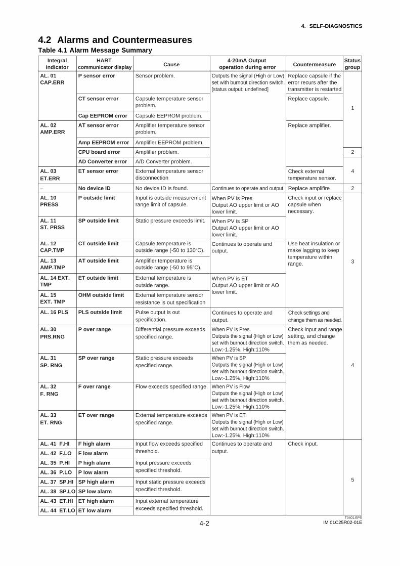
IM 01C25R02-01E4-2
4. SELF-DIAGNOSTICS
4.2 Alarms and CountermeasuresTable 4.1 Alarm Message Summary
Integralindicator
HART communicator display Cause
4-20mA Output operation during error Countermeasure
Status group
AL. 01CAP.ERR
AL. 02AMP.ERR
AL. 03ET.ERR
–
AL. 10PRESS
AL. 11 ST. PRSS
P sensor error Sensor problem. Outputs the signal (High or Low) set with burnout direction switch. [status output: undefined]
Continues to operate and output. Replace amplifire
Replace capsule if the error recurs after the transmitter is restarted
F over range Flow exceeds specified range. When PV is FlowOutputs the signal (High or Low) set with burnout direction switch.Low:-1.25%, High:110%
Check input and range setting, and change them as needed.
Check input.
Check input or replace capsule when necessary.
Use heat insulation or make lagging to keep temperature within range.
CT sensor error Capsule temperature sensor problem.
Cap EEPROM error Capsule EEPROM problem.
AT sensor error Amplifier temperature sensor problem.
ET sensor error External temperature sensor disconnection
No device ID No device ID is found.
P outside limit Input is outside measurement range limit of capsule.
Check externaltemperature sensor.
Check settings and change them as needed.
When PV is PresOutput AO upper limit or AOlower limit.
When PV is SPOutput AO upper limit or AOlower limit.
When PV is ETOutput AO upper limit or AOlower limit.
Continues to operate and output.
Continues to operate and output.
AL. 12CAP.TMP
CT outside limit Capsule temperature is outside range (-50 to 130!C).
AL. 13AMP.TMP
AT outside limit Amplifier temperature is outside range (-50 to 95!C).
Amp EEPROM error Amplifier EEPROM problem.
CPU board error Amplifier problem.
AD Converter error A/D Converter problem.
2
2
3
4
5
4
SP outside limit Static pressure exceeds limit.
AL. 14 EXT. TMP
ET outside limit External temperature is outside range.
Input flow exceeds specified threshold.
Input pressure exceeds specified threshold.
Input static pressure exceeds specified threshold.
Input external temperature exceeds specified threshold.
AL. 15EXT. TMP
OHM outside limit External temperature sensor resistance is out specification
AL. 16 PLS
AL. 32F. RNG
P over range Differential pressure exceeds specified range.
When PV is Pres.Outputs the signal (High or Low) set with burnout direction switch.Low:-1.25%, High:110%
AL. 30PRS.RNG
SP over range Static pressure exceeds specified range.
When PV is SPOutputs the signal (High or Low) set with burnout direction switch.Low:-1.25%, High:110%
AL. 31SP. RNG
ET over range External temperature exceeds specified range.
When PV is ETOutputs the signal (High or Low) set with burnout direction switch.Low:-1.25%, High:110%
Continues to operate and output.
AL. 33ET. RNG
F high alarmAL. 41 F.HI
F low alarmAL. 42 F.LO
P high alarmAL. 35 P.HI
P low alarmAL. 36 P.LO
SP high alarmAL. 37 SP.HI
SP low alarmAL. 38 SP.LO
ET high alarmAL. 43 ET.HI
ET low alarmAL. 44 ET.LO
PLS outside limit Pulse output is out specification.
Replace capsule.
Replace amplifier.
1
T0401.EPS

IM 01C25R02-01E4-3
4. SELF-DIAGNOSTICS
AL. 50P. LRV
Check settings and change them as needed.
Holds at the output value that existed immediately before the error occurred.
Adjust settings and change them as needed.
Continues to operate and output.
Check settings and change them as needed.
Holds at the output value that existed immediately before the error occurred.
Illegal P LRV
AL. 51P. URV
Illegal P URV
AL. 58FL. ADJ
F set outside Range
AL. 52P. SPN
Illegal P SPAN
AL. 53P. ADJ
P SPAN trim err
P ZERO trim err
AL. 54SP. RNG
Illegal SP LRV
Illegal SP URV
Illegal SP SPAN
Adjust settings and change them as needed.
Continues to operate and output.
Check settings and change them as needed.
Adjust settings and change them as needed.
Holds at the output value that existed immediately before the error occurred.
Continues to operate andoutput.
AL. 55SP. ADJ
SP SPAN trim err
SP ZERO trim err
Check settings and change them as needed.
Check Simulation Mode.
Leave from Temperature Fix Mode.
Holds at the output value that existed immediately before the error occurred.
AL. 57ET. ADJ
ET SPAN trim err
ET ZERO trim err
AL. 56ET. RNG
Illegal ET LRV
Illegal ET URV
Illegal ET SPAN
Specified value is outside of setting range.
AL. 59PLS.ADJ
Normal calculation.PLS set err Specified value is outside of setting Pulse output.
AL. 79OV. DISP
Continues to operate and output.
(None) Displayed value exceeds limit.
AL. 90SIM
Simulate input output.Simulate Mode Under Simulation Mode.
- Temp. Output Fix at 4mA.ET Fixed Mode Under Temperature Fix Mode.PV is ET
Specified value is outside of setting range.
6
7
7
8
7
-
5
7
8
T0403.EPS
Integralindicator
HART communicator display Cause
4-20mA Output operation during error Countermeasure
Status group
If one of following alarm occurs, all the output data is hold to the value before alarm occurs.
AL.01 (CAP. ERR)AL.02 (AMP. ERR)AL.03 (ET. ERR)

IM 01C25R02-01E4-4
4. SELF-DIAGNOSTICS
Table 4.2 HART Communicator Error Messages
T0402.EPS
—
—
Error message Probable cause Countermeasure
Invalid selection
Passed Parameter Too Large
Passed Parameter Too Small
Too Few Data Bytes Received
In Write Protect Mode
Lower Range Value too High
Lower Range Value too Low
Upper Range Value too High
Upper Range Value too Low
Span too Small
Applied Process too High
Applied Process too Low
New Lower Range Value Pushed Upper Range Value Over Sensor Limit
Excess Correction Attempted
Small Char. did not convert successfully
Not in fixed current mode
In Multidrop Mode
Not write Protect
Set value is too high.
Set value is too low.
Operation is set in the Write Protect mode.
LRV set point is too high.
LRV set point is too low.
URV set point is too high.
URV set point is too low.
Set span is too small.
Applied pressure is too high.
Applied pressure is too low.
The shift of URV according to the new LRV setting exceeds USL.
Amount of correction is too much.
Characters are not convertible. e.g. %
The fixed current mode is desired but not set in that mode.
Operation is set in the multi-drop mode.
Operation is set without a password.
Change the setting.
Correct the setting.
—
—
—
—
Adjust the applied pressure.
Change the URV setting within the range of USL.
Adjust the amount.
Set in the fixed current mode.
Change the range.

IM 01C25R02-01E5-1
5. PARAMETER SUMMARY
5. PARAMETER SUMMARYFunction Label Item Contents Default value Handling Fast key
sequencesAnalog output AO alm typ
AO lower limitAO upper limitAuto recover
Analog output alarm typeLower limit of analog outputUpper limit of analog outputAuto-recover from hardware error
High or Low3.8000 to 21.6000 mA3.8000 to 21.6000 mAOff or On
3.8000 mA21.6000 mAOn
RWWW
1, 4, 3, 2, 51, 4, 3, 2, 71, 4, 3, 2, 81, 4, 3, 2, 6
Flow setup Flow DampFlow LRVFlow URVVol Flow Base Dens
Damping time constant for flowLower range value for flowUpper range value for flowVolume Flow Base Density Value
0.00 to 100.00 sec WWWW
1, 4, 2, 1, 41, 4, 2, 1, 11, 4, 2, 1, 21, 4, 2, 1, 5, 2
Burst mode Burst mode Burst mode Off or On Off W 1, 4, 3, 3, 3Burst operation option Burst option Burst option Off or On Off W 1, 4, 3, 3, 4
Date Date Date **/**/** W 1, 3, 4, 1Descriptor Descriptor Descriptor 16 alphanumerics W 1, 3, 4, 2
Loop test Loop test Test output setting Within AO lower and upper limits M 1, 2, 2
Universal rev Universal revision 16 alphanumerics R 1, 4, 5, 1, ↓, 1
Burst transmitter values Burst Xmtr Vals Burst transmitter values M 1, 4, 3, 3, 5
Analog output trim Clear D/A trimD/A trimScaled D/A trim
Reset analog output trimAnalog output trim with ammeterAnalog output trim with voltmeter
MMM
1, 2, 3, 2, 31, 2, 3, 2, 11, 2, 3, 2, 2
Device information
Display setup
DP setup
Dev idDistributorDrain vent matlExtra No.Ext SW
Device IDYokogawaDrain and vent plug materialCustomizaion numberExternal zeroing permission Disabled or Enabled Enabled
NormalAs specified2As specified2
2
2
2
No
RRWRW
1, 4, 5, 1, ↓, 61, 4, 5, 1, ↓, 71, 4, 5, 2, 51, 4, 5, 1, ↓, 41, 4, 5, 1, 9
Fill fluidFinal asmbly numFld dev revGasket matlIsoltr matl
Fill fluidFinal assembly numberField device revisionGasket materialCapsule material
WWRWW
1, 4, 5, 2, 21, 4, 5, 1, ↓, 51, 4, 5, 1, ↓, 21, 4, 5, 2, 31, 4, 5, 2, 1
Mftr DateMS Code 1MS Code 2MS Code 3Num of RS
Manufactured dateMemo field for MS code 1Memo field for MS code 2Memo field for MS code 3Number of remote seal
16 alphanumerics16 alphanumerics16 alphanumerics
Normal or High resolution-32000 to 32000, unit specified in Set Engr Unit0 to 4-32000 to 32000, unit specified in Set Engr Unit0 to 4
RWWWW
1, 4, 5, 1, _, 31, 4, 5, 1, 51, 4, 5, 1, 61, 4, 5, 1, 71, 4, 5, 2, 9
Process Conn matlProcess Conn sizeProcess Conn typePT100 Serial No.RS fill fluid
Process connection materialProcess connection sizeProcess connection typeSerial number of PT100Fill fluid of remote seal
WWWWW
1, 4, 5, 2, 41, 4, 5, 2, 61, 4, 5, 2, 81, 4, 5, 1, ↓, 81, 4, 5, 2, ↓
RS Isoltr matlRS typeSerial No.Sofftware revStyle No.
Remote seal materialRemote seal typeSerial numberSoftware revisionStyle number Style number of product
WWRRR
1, 4, 5, 2, 71, 4, 5, 2, ↓1, 4, 5, 1, ↓, 21, 4, 5, 1, ↓, 31, 4, 5, 1, ↓, 1
TF disp point Decimal place for total flow 0 to 4 W2 1, 4, 4, 3, 5
Pres USL Upper sensor limit for differential pressure 0 to 4 R 1, 4, 2, 2, 5
Disp % ResoEngr LRVEngr pointEngr URVET disp point
% display resolutionUse set lower range valueDecimal place for user setUse set upper range valueDecimal place for external temperature
WWWWW
1, 4, 4, 21, 4, 4, 4, 11, 4, 4, 4, 51, 4, 4, 4, 21, 4, 4, 3, 4
OnPV %
Not used
Not usedNot used
Off or OnPV %, Flow, Pres, SP, EXT. TEMP, ENGR.PV, or TOTAL FLOWPV %, Flow, Pres, SP, EXT. TEMP, ENGR.PV, TOTAL FLOW, or Not used(Ditto)(Ditto)
Bar indicatorDisp1
Disp2
Disp3Disp4
Bar indicatorLCD output 1
LCD output 2
LCD output 3LCD output 4
WW
W
WW
1, 4, 4, 51, 4, 4, 1, 1
1, 4, 4, 1, 2
1, 4, 4, 1, 31, 4, 4, 1, 4
Flow disp pointModify Engr UnitPres disp pointSet Engr UnitSP disp point
Decimal place for flowUser set engineering unitDecimal place for differential pressureEngineering unit selectDecimal place for static pressure
0 to 4
0 to 4
0 to 4
WMWMW
1, 4, 4, 3, 11, 4, 4, 4, 71, 4, 4, 3, 21, 4, 4, 4, 61, 4, 4, 3, 3
Pres DampPres Min SpanPres LRVPres LSLPres URV
Damping time constant for DPMinimum span for differential pressureLower range value for differential pressureLower sensor limit for differential pressureUpper range value for differential pressure
0.00 to 100.00 sec WRWRW
1, 4, 2, 2, 71, 4, 2, 2, 61, 4, 2, 2, 11, 4, 2, 2, 41, 4, 2, 2, 2
ET setup ET DampET FixedET Min SpanET LRVET LSL
Damping time constant for ETExternal temperature fix modeMinimum span for external temperatureLower range value for ETLower sensor limit for ET
0.00 to 100.00 secNo,Yes, or FALL BACK
WWRWR
1, 4, 2, 4, 71, 4, 2, 4, 8, 11, 4, 2, 4, 61, 4, 2, 4, 11, 4, 2, 4, 4
Keypad Input Change PV AssgnPV DampPV isPV LRVPV URV
Change the allocation to PVDamping time constant for PVCurrent PVLower range value for PVUpper range value for PV
MWRWW
hot key, 1, 2hot key, 1, 6hot key, 1, 1hot key, 1, 4hot key, 1, 5
Error log Error log ClearError log view
Clear error recordsError records Log1 (latest) to log4
MM
1, 2, 4, 21, 2, 4, 1
ET URVET USLFixed ET Val
Upper range value for ETUpper sensor limit for ETTemperature value at ET fix mode
WRW
1, 4, 2, 4, 21, 4, 2, 4, 51, 4, 2, 4, 8, 2
*1: Handling: R-Read only, W-Read & Write, M-Method.

IM 01C25R02-01E5-2
5. PARAMETER SUMMARY
Function Label Item Contents Default value Handling Fast key sequences
Process Alerts Digital OutputDO FrequencyDO SelectDO Signal type
DO Test
Display of contact outputFrequency of Digtal OutputContact output selectSignal type select
Test output contact
Off or On
Combination of Pres, SP, Temp, and FlowOn When Al. Detect, Off When Al. Detect, Scaled Pulse, or Frequency
Off WWWW
M
1, 4, 3, 1, 71, 4, 3, 4, 5, 51, 4, 3, 4, 5, 21, 4, 3, 4, 5, 3
1, 4, 3, 4, 5, 4
Process variables Amp tempCap tempEngr DispEngr exp
Engr Unit
Amplifier temperatureCapsule temperatureUser scaled valueExponents
User set engineering unit
-32000 to 32000, unit specified in Set Engr Unitx1, x10, x100, or x1000
Unit specified in Set Engr Unit
As specified or -
RRRRRW
R
1, 1, 7, 71, 1, 7, 61, 1, 401, 1, 5
1, 1, 6
Sensor trim
Basic Flow Calc
SP trimSim Flow ModeSim PresSim Pres UnitSim SPSim SP Unit
Static pressure trimSimulate Flow ModeDifferential pressure value for simulateDifferential pressure unit for simulateStatic pressure value for simulateStatic pressure unit for simulate
MWWWWW
1, 2, 3, 4, 11, 4, 7, 11, 4, 7, 31, 4, 7, 21, 4, 7, 51, 4, 7, 4
ETFlowPresPVPV %
External temperature valueFlow valueDifferential pressure valuePV valuePV value in %
Unit specified in PV Unit-2.50 to 110.00%
RRRRRRRR
1, 1, 7, 41, 1, 7, 11, 1, 7, 221, 1, 2
Flow Calc FixedFlow Calc modeFluid TypeRef SPRef Temp
Calculation fixation value of flowiFlow cauculation modeFluid typeReferrence static pressureReferrence temperature
Auto Comp. Mode or Basic ModeWWWWW
1, 4, 8, 31, 4, 8, 11, 4, 8, 21, 4, 8, 41, 4, 8, 5
Status Status group 1Status group 2Status group 3Status group 4Status group 5
Device status information for hardwareDevice status information for hardwareDevice status information for processDevice status information for processDevice status information for process
RRRRR
1, 2, 1, 1, 11, 2, 1, 1, 21, 2, 1, 1, 31, 2, 1, 1, 41, 2, 1, 1, 5
Total Flow Cvt ValFreq at 100%Pulse rateModify UnitSet Base Unit
Convert value for total flow base unitDigtal otput fequency at 100%Pulse rateModify flow base unitSet total flow base unit
WWWMM
1, 4, 2, 5, 6, 11, 4, 2, 5, 41, 4, 2, 5, 31, 4, 2, 5, 6, 31, 4, 2, 5, 6, 2
Clear ET trimClear P trimClear SP trimET trimPres trim
Reset ET trim to factory settingReset pressure trim to factory settingReset SP trim to factory settingExternal temperature trimPressure trim
MMMMM
1, 2, 3, 5, 21, 2, 3, 3, 21, 2, 3, 4, 21, 2, 3, 5, 11, 2, 3, 3, 1
ET AlertFlow AlertPres AlertSP Alert
Set alert for external temperatureSet alert for flowSet alert for differential pressureSet alert for static pressure
MMMM
1, 4, 3, 4, 31, 4, 3, 4, 41, 4, 3, 4, 11, 4, 3, 4, 2
Low cut Low cutLow cut mode
Low cutLow cut mode
0.00 to 20.00%Off or On
10.00%Off
WW
1, 3, 5, 11, 3, 5, 2
Number of requested preambles
Numreqpreams Number of requested preambles R 1, 4, 3, 3, 2
Master test Master test Master test 32 alphanumerics M 1, 2, 2, 3Message Message Message Off or On As specified W 1, 3, 4, 3
Tag Tag Tag number 16 alphanumerics
Reset, Start or Stop
W 1, 2, 2, 3Test key Test key Special maintenance parameter
As specifiedM 1,4,6
Model Model Model W 1, 3, 4, 5
Piping orientation H/L Swap Impulse piping accessing direction R 1, 3, 5, 3Poll address Poll addr Poll address for multidrop use 0 to 15
Normal or Reverse0Normal
W 1, 4, 3, 3, 1
Self test Self test Self-diagnostics 0 to 15 0 M 1, 2, 1, 2
Temp K1 The first in temperature correction coefficient for liquid W 1, 4, 8, 6
PV AOSPTotal Flow
Analog output currentStatic pressure valueTotal flow value
3.8000 to 21.6000 mA RRRRR
31, 1, 7, 31, 1, 7, 5
*1: Handling: R-Read only, W-Read & Write, M-Method.
Sim TempSim Temp Unit
Temperature value for simulateTemperature unit for simulate
WW
1, 4, 7, 71, 4, 7, 6
Total Flow ModeTotal Flow Unit
Total flow modeCurrent total flow unit
WW
1, 4, 2, 5, 51, 4, 2, 5, 2
SP setup A/G Select
Atm. Pres ValueSP DampSP H/L SelectSP Min Span
Damping time constant for SP
Minimum span for static pressure
-32000 to 32000, unit specified in Set Engr Unitx1, x10, x100, or x1000
Unit specified in Set Engr Unit
As specified or -
W
WWWR
1, 4, 2, 3, 8
1, 4, 2, 3, ↓1, 4, 2, 3, 71, 4, 2, 3, 91, 4, 2, 3, 6
SP LRVSP LSLSP URVSP USL
Lower range value for static pressureLower sensor limit for static pressureUpper range value for static pressureUpper sensor limit for static pressure
WRWR
1, 4, 2, 3, 11, 4, 2, 3, 41, 4, 2, 3, 21, 4, 2, 3, 5
Status group 6Status group 7Status group 8
Device status information for dataDevice status information for dataDevice status information for data
RRR
1, 2, 1, 1, 61, 2, 1, 1, 71, 2, 1, 1, 8
SV Change SV AssgnSVSV is
Change the allocation to SVSV valueCurrent SV
Unit specified in SV UnitMRR
1, 1, 8, 2, 21, 1, 8, 2, 31, 1, 8, 2, 1

IM 01C25R02-01E5-3
5. PARAMETER SUMMARY
Function Label Item Contents Default value Handling Fast key sequences
Units Density UnitET UnitFlow UnitPres UnitPV Unit
Density unitExternal temperature unitFlow unitDifferential pressure unitPV unit
WW W W W
1, 4, 2, 1, 5, 11, 3, 2, 31, 3, 2, 41, 3, 2, 1hot key, 1, 3
SP UnitSV UnitTotal Flow UnitTV Unit4V Unit
Static pressure unitSV unitTotal flow unitTV unit4V unit
WW W W W
1, 3, 2, 21, 1, 8, 2, 41, 3, 2, 51, 1, 8, 3, 41, 1, 8, 4, 4
Trim DataTrim DescTrim LocTrim Who
Trim dataTrim descriptionTrim locationTrim person
WWWW
1, 2, 3, 6, 21, 2, 3, 6, 41, 2, 3, 6, 31, 2, 3, 6, 1
Trim information
TV Change TV AssgnTVTV is
Change the allocation to TVTV valueCurrent TV
**/**/**16 alphanumerics8 alphanumerics8 alphanumerics
MRR
1, 1, 8, 3, 21, 1, 8, 3, 31, 1, 8, 3, 1
Enable wrt 10minNew passwordSoftware sealWrite protect
KeepNo
Write protection releaseUser set password for write protectionSoftware sealWrite protection indicator
MMRR
hot key, 2, 2hot key, 2, 3hot key, 2, 4hot key, 2, 1
Write protectin menu
4V Change 4V Assgn4V4V is
Change the allocation to 4V4V valueCurrent 4V
Unit specified in 4V Unit
8 alphanumerics8 alphanumericsKeep or BreakYes or No
MRR
1, 1, 8, 4, 21, 1, 8, 4, 31, 1, 8, 4, 1
*1: Handling: R-Read only, W-Read & Write, M-Method.

IM 01C25R02-01E
REVISION RECORDTitle: EJX Series HART Communication TypeManual No.: IM 01C25R02-01E
REVISION RECORD.EPS
Edition Date Page Revised Item
1st Mar. 2005 – New publication