elecraft kpa500 amplifier kit assembly instructions kpa500 kit assembly manual rev … · packages...
TRANSCRIPT

ELECRAFT KPA500
HIGH-PERFORMANCE 160 – 6 METER AMPLIFIER
KIT ASSEMBLY INSTRUCTIONS
Rev F7, March 1, 2017
E740149
Copyright © 2017, Elecraft, Inc. All Rights Reserved

1
Contents
Introduction ............................................................................................................................................... 3
Customer Service and Support ............................................................................................................................ 3
Technical Assistance ....................................................................................................................................... 3
Repair / Alignment Service ............................................................................................................................. 3
Anti Static Protection Required ................................................................................................................ 4
Preparing for Assembly ............................................................................................................................ 5
Tools Required .................................................................................................................................................... 5
Unpacking and Inventory .................................................................................................................................... 5
Screws ............................................................................................................................................................. 5
Standoffs ......................................................................................................................................................... 6
Lock Washers .................................................................................................................................................. 6
Overview of the Kit .................................................................................................................................. 7
Assembly .................................................................................................................................................. 8
Bottom Cover Feet .............................................................................................................................................. 8
Power Supply Module ....................................................................................................................................... 11
Interlock Switch and Left Side Panel Feet ........................................................................................................ 14
Rear Panel ......................................................................................................................................................... 16
RF Power Amplifier/Low Pass Filter (PA/LPF) Module .................................................................................. 21
Rectifier Board .................................................................................................................................................. 22
Mounting the Rear Panel Assembly .................................................................................................................. 25
Power Supply Wiring ........................................................................................................................................ 29
Front Panel Assembly ....................................................................................................................................... 38
Top Cover and Side Handle .............................................................................................................................. 42
Appendix A Illustrated Parts List........................................……… …………………………………..A1
Elecraft manuals with color images may be downloaded from www.elecraft.com.

2
WARNING
Dangerous Voltages Inside the KPA500 After It Has Been
Connected to Mains Power
When you have completed assembling your kit, turn to your Owner’s manual to install and configure it properly before applying mains power or attempting to operate it.
If you open the KPA500 after installing it and applying mains power:
1. Turn off the KPA500 by tapping the front panel ON switch and wait until the fan stops. (The fan drains the power supply to a safe voltage.)
2. Place the rear panel rocker switch in off (O) position and disconnect mains power from the rear panel.
There are no dangerous voltages present in the KPA500 during the assembly of the kit if you follow the procedures
in this manual.

3
Introduction This manual covers the assembly of your KPA500 160 through 6 meter amplifier kit. Only a few basic hand tools are needed (see page 5) to perform the installation. No soldering is required to assemble this kit.
Complete instructions for installing and operating our KPA500 are found in the KPA500 Owner’s manual.
Customer Service and Support Technical Assistance You can send e-mail to [email protected] and we will respond quickly - typically the same day Monday through Friday. Telephone assistance is available from 9 A.M. to 5 P.M. Pacific time (weekdays only) at 831-763-4211. Please use e-mail rather than calling when possible since this gives us a written record of the details of your problem and allows us to handle a larger number of requests each day. Repair / Alignment Service (We want to make sure everyone succeeds!) If necessary, you may return your Elecraft product to us for repair or alignment. (Note: We offer unlimited email and phone support to get your kit running, so please try that route first as we can usually help you find the problem quickly.) IMPORTANT: You must contact Elecraft before mailing your product to obtain authorization for the return, what address to ship it to and current information on repair fees and turnaround times. (Frequently we can determine the cause of your problem and save you the trouble of shipping it back to us.) Our repair location is different from our factory location. We will give you the address to ship your kit to at the time of repair authorization. Packages shipped without authorization will incur an additional shipping charge for reshipment to our repair depot.
Elecraft's 1-Year Limited Warranty This warranty is effective as of the date of first consumer purchase (or if shipped from factory, date product is shipped to customer). It covers both our kits and fully assembled products. For kits, before requesting warranty service, you should fully complete the assembly, carefully following all instructions in the manual. Who is covered: This warranty covers the original owner of the Elecraft product as disclosed to Elecraft at the time of order. Elecraft products transferred by the purchaser to a third party, either by sale, gift or other method, who is not disclosed to Elecraft at the time of original order, are not covered by this warranty. If the Elecraft product is being bought indirectly for a third party, the third party's name and address must be provided to Elecraft at time of order to insure warranty coverage.
What is covered: During the first year after date of purchase, Elecraft will replace defective or missing parts free of charge (post-paid). We will also correct any malfunction to kits or assembled units caused by defective parts and materials. Purchaser pays inbound shipping to Elecraft for warranty repair, Elecraft will pay shipping to return the repaired equipment to you by UPS ground service or equivalent to the continental USA and Canada. Alaska, Hawaii and outside U.S. and Canada actual return shipping cost paid by owner.
What is not covered: This warranty does not cover correction of kit assembly errors. It also does not cover misalignment; repair of damage caused by misuse, negligence, or builder modifications; or any performance malfunctions involving non-Elecraft accessory equipment. The use of acid-core solder, water-soluble flux solder, or any corrosive or conductive flux or solvent will void this warranty in its entirety. Also not covered is reimbursement for loss of use, inconvenience, customer assembly or alignment time, or cost of unauthorized service.
Limitation of incidental or consequential damages: This warranty does not extend to non-Elecraft equipment or components used in conjunction with our products. Any such repair or replacement is the responsibility of the customer. Elecraft will not be liable for any special, indirect, incidental or consequential damages, including but not limited to any loss of business or profits.

4
Anti Static Protection Required We strongly recommend you take the following anti-static precautions (listed in order of importance) to avoid ESD (Electro Static Discharge) damage:
Leave ESD-sensitive parts in their anti-static packaging until you install them. The packaging may be a special plastic bag or the component’s leads may be inserted in conductive foam. Parts which are especially ESD-sensitive are identified in the parts list and in the assembly procedures.
Wear a conductive wrist strap with a series 1-megohm resistor. If you do not have a wrist strap, touch a bare metal ground briefly before touching any sensitive parts to discharge your body. Do this frequently while you are working. You can collect a destructive static charge on your body just sitting at the work bench.
WARNING
DO NOT attach a ground directly to yourself without a current-limiting resistor as this poses a serious shock hazard. A wrist strap must include a 1-megohm resistor to limit the current flow. If you choose to touch an unpainted, metal ground to discharge yourself, do it only when you are not touching any live circuits with your other hand or any part of your body.
Use a grounded anti-static mat on your work bench.
No soldering is required but if you choose to use a soldering iron for any reason, be sure your iron has an ESD-safe grounded tip tied to the same common ground used by your mat or wrist strap.
We strongly recommend you take the following anti-static precautions (listed in order of importance) to avoid trouble:
• Leave ESD-sensitive parts in their anti-static packaging until you install them. The packaging may be a special plastic bag or the component’s leads may be inserted in conductive foam. Parts which are especially ESD-sensitive are identified in the parts list and in the assembly procedures.
• Wear a conductive wrist strap with a series 1-megohm resistor. If you do not have a wrist strap, touch a ground briefly before touching any sensitive parts to discharge your body. Do this frequently while you are working. You can collect a destructive static charge on your body just sitting at the work bench. DO NOT attach a ground directly to yourself as this poses a serious shock hazard.
• Use a grounded anti-static mat on your work bench.
• If you choose to use a soldering iron to work on your KPA500 for any reason, be sure your iron has an ESD-safe grounded tip tied to the same common ground used by your mat or wrist strap.

5
Preparing for Assembly Tools Required
1. #0, #1 and #2 size Phillips screwdrivers. To avoid damaging screws and nuts, a power screwdriver is not recommended. Use the screwdriver that best fits the screw in each step.
2. Needle-nose pliers.
3. Two 1/2” or adjustable wrenches (for transformer mounting).
4. Soft cloth or clean, soft static dissipating pad to lay cabinet panels on to avoid scratching.
5. DMM for making resistance and continuity measurements.
The following tools are strongly recommended:
1. ESD wrist strap.
2. Static dissipating work pad.
3. Tweezers are very handy for positioning parts in cramped spaces.
4. Rule for measuring screw lengths.
Unpacking and Inventory
CAUTION
Do not handle the circuit boards without anti-static protection! Doing so may damage sensitive components. See Anti Static Protection Required on page 4 for important information before proceeding.
Before starting construction, do a complete inventory, comparing the parts in your kit with the parts list in Appendix A to familiarize yourself with all of the parts and to ensure the kit is complete. Look in the sealed envelopes to identify their contents, but do not mix them up. Some screws are very similar in length, but must be used in the correct locations as described in the procedure.
All dimensions given in the assembly procedure are provided in both US customary (often called English) and metric measurements. The native dimensions of the parts are in US Customary units. Approximate metric equivalents are given to assist those more familiar with that system to identify the correct parts.
Screws
A number of different types and sizes of screws and washers are used in the assembly. It is very important that you use the screw specified in each location or your finished KPA500 may not fit together properly. In some places, using the wrong size screw may damage components. Smaller screws are identified by one or two digits denoting their diameter followed by a two-digit number indicating the threads per inch. For example, a 2-56 screw is smaller in diameter than a 4-40, and so on. In this case, the 56 indicates 56 threads per inch and 40 indicates 40 threads per inch. Mating nuts are identified in the same way: A 4-40 nut mates with a 4-40 screw. Washers are identified by only the first digit since only the diameter is significant. For example, a #4 washer fits a 4-40 screw.
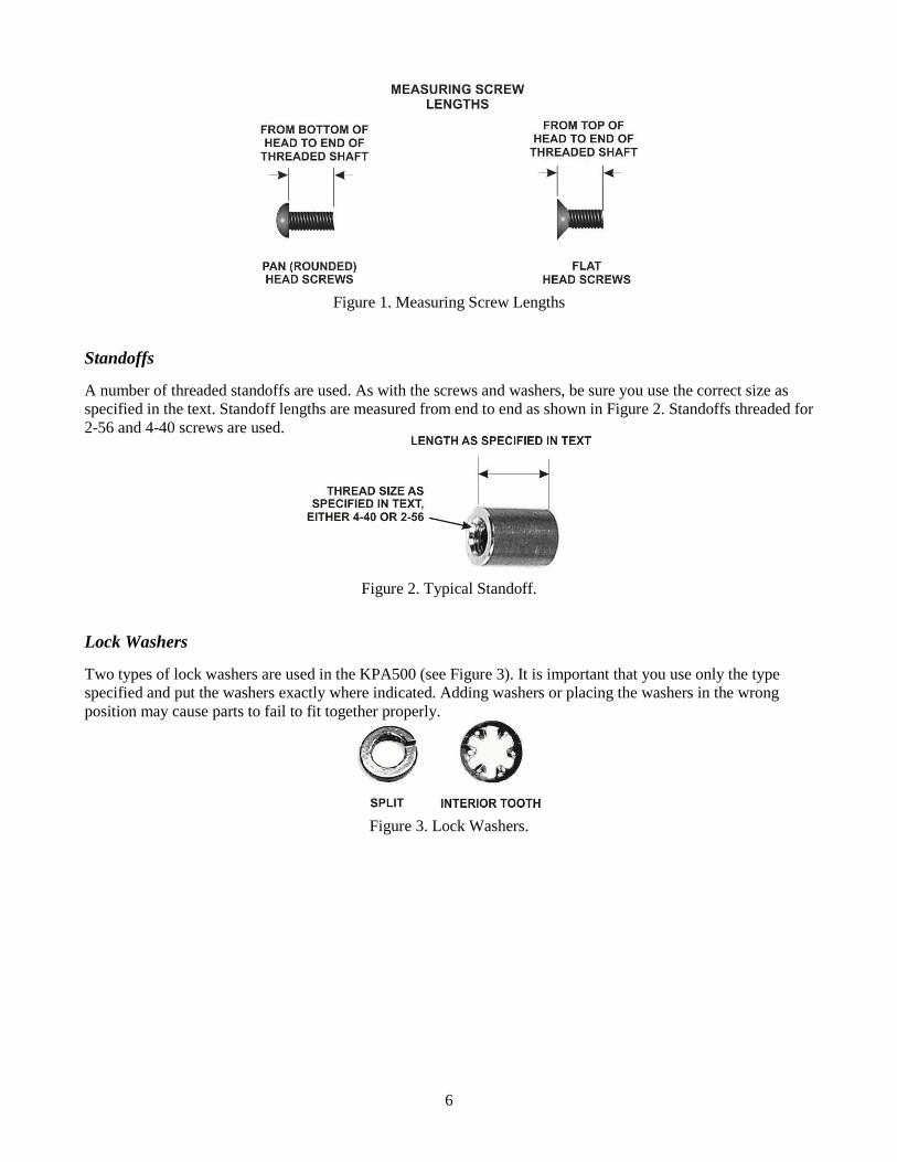
The length of the screws called for in the text is measured as shown in Figure 1. Since the native measurements are in inches, the metric values shown throughout the text are approximate but accurate enough to allow you to identify the correct length.
6
Figure 1. Measuring Screw Lengths
Standoffs
A number of threaded standoffs are used. As with the screws and washers, be sure you use the correct size as specified in the text. Standoff lengths are measured from end to end as shown in Figure 2. Standoffs threaded for 2-56 and 4-40 screws are used.
Figure 2. Typical Standoff.
Lock Washers
Two types of lock washers are used in the KPA500 (see Figure 3). It is important that you use only the type specified and put the washers exactly where indicated. Adding washers or placing the washers in the wrong position may cause parts to fail to fit together properly.
Figure 3. Lock Washers.

7
Overview of the Kit Figure 4 is a top view of the KPA500 with the top cover removed. The chassis is divided into two major areas by a bracket (called the Z-bracket due to its shape) that runs down the middle from front to back. The RF circuitry is on the right in this view, and the power supply is on the left.
The RF circuitry is supplied assembled, factory tested and aligned. It consists of a “sandwich” of two boards; a power amplifier board mounted on the heat sink and an output low pass filter board below it.
On the left is the power supply, dominated by the toroidal power transformer. Largely hidden by the I/O board is the power supply module that contains the regulators and other components of the power supply except the rectifiers. The rectifiers are mounted on a separate board near the front that uses the Z-bracket for a heat sink.
The I/O board provides the circuitry needed by the RS232, AUX and other rear panel interface connectors.
The front panel board contains all the control circuitry, including the circuitry required by the front panel switches and displays. The front panel board is connected to the I/O board by a ribbon cable that runs alongside the power transformer.
Figure 4. Assembled KPA500 with Top Cover Removed.

8
Assembly
IMPORTANT ASSEMBLY INFORMATION A variety of screws and fasteners are used to assemble your KPA500:
• Use your rule to check the length of screws and standoffs before installing them. Some components are only 1/16” (1.6 mm) different from others but using the wrong size may result in parts not fitting correctly, possibly damaging electrical and mechanical components. See Screws on page 5 and Standoffs on page 6 for more measurement instructions.
• Loosen screws as needed for a proper fit. When mounting parts with multiple screws or adjacent parts that fit together, such as the exterior cabinet panels, loosen adjacent mounting screws as needed to adjust the parts for the best fit. Be certain you re-tighten the screws before proceeding.
• Ensure all screws are tight. A loose screw can cause both mechanical and electrical problems such as intermittent operation.
• Threads can be easily stripped if too much force is applied when tightening screws. Use the correct size hand tool and apply only moderate torque. Do not use a power screwdriver!
Bottom Cover Feet
Locate the bottom cover and install the tilt stand as shown in Figure 5.
• First mount one of the feet on the bottom (fully painted) side of the cover, taking care to position it with the cut-away for the stand as shown in the figure. Use the correct length screws with the screw heads on the inside of the bottom cover and the nuts with captive star washers in the feet as shown in the figure. Do not tighten the screws on the foot. Simply start the screws into the nuts so the foot remains loose.
• Then insert the tilt stand laying flat against the bottom cover and add the second foot. Put the screw head on the inside of the bottom cover just as you did with the first foot.
• After starting the screws in the second foot, tighten all four screws.
• Test the tilt stand action. It should be held tightly against the bottom cover until it is pulled up nearly perpendicular with the bottom, then it should snap into position.
• Return the tilt stand to its position against the bottom cover.
9
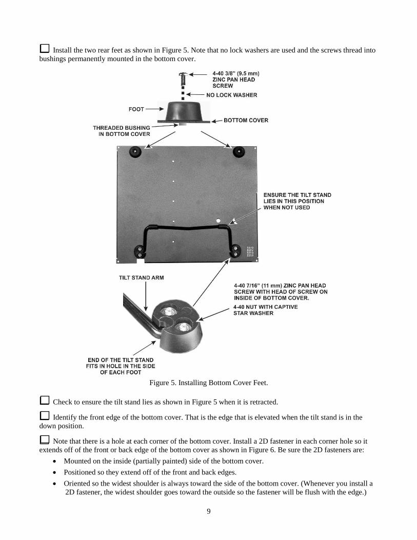
Install the two rear feet as shown in Figure 5. Note that no lock washers are used and the screws thread into bushings permanently mounted in the bottom cover.
Figure 5. Installing Bottom Cover Feet.
Check to ensure the tilt stand lies as shown in Figure 5 when it is retracted.
Identify the front edge of the bottom cover. That is the edge that is elevated when the tilt stand is in the down position.
Note that there is a hole at each corner of the bottom cover. Install a 2D fastener in each corner hole so it extends off of the front or back edge of the bottom cover as shown in Figure 6. Be sure the 2D fasteners are:
• Mounted on the inside (partially painted) side of the bottom cover. • Positioned so they extend off of the front and back edges. • Oriented so the widest shoulder is always toward the side of the bottom cover. (Whenever you install a
2D fastener, the widest shoulder goes toward the outside so the fastener will be flush with the edge.)
10
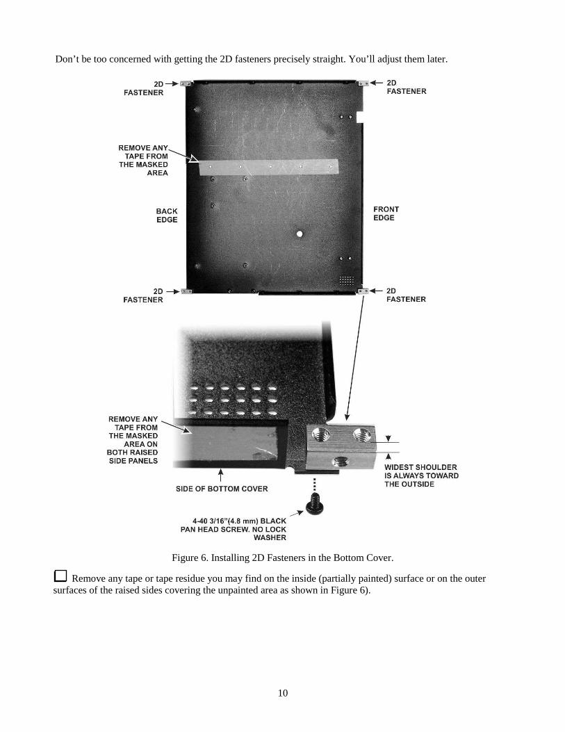
Don’t be too concerned with getting the 2D fasteners precisely straight. You’ll adjust them later.
Figure 6. Installing 2D Fasteners in the Bottom Cover.
Remove any tape or tape residue you may find on the inside (partially painted) surface or on the outer surfaces of the raised sides covering the unpainted area as shown in Figure 6).

11
Power Supply Module
Locate the Power Supply Module shown in Figure 7. Note the three metal-tabbed TO220 size I.C.s mounted at one end.
Figure 7. Power Supply Module I.C.s.
Remove the paper backing from the thermal insulator and carefully place it on U3 so that it completely covers all the exposed metal as shown in Figure 8. The other two I.C.s do not need insulators.
Figure 8. Thermal Insulator Mounted on U3.

12
Locate the heat spreader (see Figure 9). Note that it has six threaded holes; three are larger than the others and the holes are spaced to match the spacing of the I.C.s on the power supply module. The three holes indicated in the figure will be used to attach the spreader to the I.C.s. The other three holes will be used later to attach the heat spreader to the KPA500’s enclosure side panel. The spreader must be oriented as shown or the larger holes will not line up with the holes in the side panel.
Figure 9. Power Supply Module Heat Spreader Orientation.
Attach the heat spreader to the three I.C.s as shown in Figure 10. Bend the I.C. leads as shown to allow you to use a screwdriver to tighten the screws. Be sure to install the nylon shoulder washer in the hole of U3 (the I.C. with the thermal insulator) so the screw does not touch any part of the metal tab. Do not over-tighten the screw; you can crush the shoulder washer.
Do not bend the leads more than necessary or you may break a lead.
Figure 10. Mounting the Heat Spreader on the Power Supply Module.
13
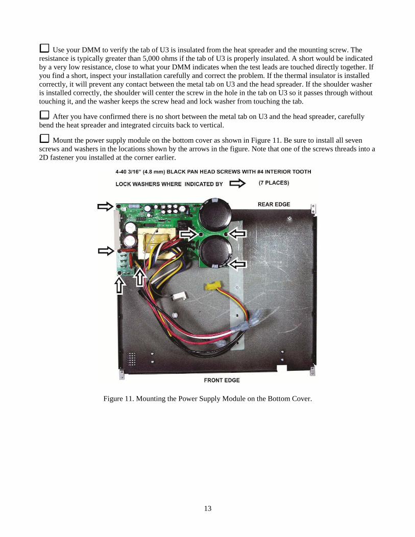
Use your DMM to verify the tab of U3 is insulated from the heat spreader and the mounting screw. The resistance is typically greater than 5,000 ohms if the tab of U3 is properly insulated. A short would be indicated by a very low resistance, close to what your DMM indicates when the test leads are touched directly together. If you find a short, inspect your installation carefully and correct the problem. If the thermal insulator is installed correctly, it will prevent any contact between the metal tab on U3 and the head spreader. If the shoulder washer is installed correctly, the shoulder will center the screw in the hole in the tab on U3 so it passes through without touching it, and the washer keeps the screw head and lock washer from touching the tab.
After you have confirmed there is no short between the metal tab on U3 and the head spreader, carefully bend the heat spreader and integrated circuits back to vertical.
Mount the power supply module on the bottom cover as shown in Figure 11. Be sure to install all seven screws and washers in the locations shown by the arrows in the figure. Note that one of the screws threads into a 2D fastener you installed at the corner earlier.
Figure 11. Mounting the Power Supply Module on the Bottom Cover.

14
Interlock Switch and Left Side Panel Feet
Locate the left side panel and remove any masking tape found on the inside (partially painted) surface.
Locate the interlock switch and mount it on the inside (not fully painted) side of the side panel as shown in Figure 12. The top cover will press against the lever on the switch to enable the high voltage supply when the top cover is closed.
Figure 12. Mounting the Interlock Switch on the Left Side Panel.
Install the four rubber side feet in the large holes in the left side panel. Be sure the large flat side of each foot is on the outside (fully painted side) of the panel. The feet should be fully seated in the holes as shown in Figure 13. Two suggested procedures for doing this are as follows:
Press Method: Wet the tip of the foot with a tiny amount of
soap. (Do not use petroleum jelly or oils. They can deteriorate the rubber over time).
Place the foot, tip up, on a solid work surface. Position the panel with the outside (fully painted
side) toward the foot with the hole in the panel against the tip and press down. The tip should slip through the hole without further help. If necessary, grip the tip and pull with your long-nose pliers, working it from side to side until the shoulder opens against the inside of the panel. Do not use excessive force. You can tear the foot apart.
Wipe any excess soap off of the panel or foot.
Twist Method: Press the foot against the outside (fully
painted side) of the panel so the tip is in the hole at an angle.
While pressing the tip into the hole, twist the foot so the edge of the tip grabs the inside edge of the hole.
Continue pressing and twisting until the tip is fully inside the panel all the way around its circumference. Do not twist with excessive force. You can tear the foot apart.
Figure 13. Side Panel Foot Installation.

15
Mount the left side panel on the bottom cover as shown in Figure 14. Note that two different screw sizes are used. Loosely start all the screws so the panel can move slightly as needed to align all the holes. Tighten all the screws.
Note: This side panel is installed now to provide a secure, stable chassis for installing components. Later, it will be removed temporarily to install the power transformer. The transformer is installed as late as possible since its weight makes handling the chassis more difficult.
Figure 14. Mounting the Left Side Panel on the Bottom Cover.
Mount a 2D fastener at the top of the left side panel near the front end. The fastener goes on the inside surface of the panel, parallel with the top edge and with the wide shoulder against the panel (see Figure 15).
Figure 15. Mounting a 2D Fastener on the Left Side Panel.
Mount another 2D fastener at the top of the left side panel near the back (above the power supply module), oriented just like the 2D fastener you installed near the front in the last step. That will leave only one open hole near the top center of the side panel. It will be used later.
Set the bottom cover assembly aside in a safe place until it is called for later.

16
Rear Panel
Locate the rear panel and remove any masking tape found on the inside (partially painted) surface.
Peel the serial number provided for your KPA500 off of its protective backing and place it on the rear panel as shown in Figure 16. .
Figure 16. Mounting the Serial Number.
Locate the terminal strip board and the flat terminal strip insulator. If not already done, bend down one side of each terminal as shown in Figure 17.
Figure 17. Preparing the Terminal Strip Board.

17
On the rear panel, place two screws through the holes just below the word CAUTION near the top of the panel with the screw heads on the outside. On the inside surface of the rear panel, install the terminal strip insulator and terminal strip as shown in Figure 18.
Figure 18. Installing Rear Panel Terminal Strip.
Use your DMM to check for shorts between the terminal strips and the bare metal on the rear panel. The DMM should indicate whatever it normally shows when the probes are not touching.
Install the fan with the finger guard over the large opening in the rear panel as shown in Figure 19. Each screw must pass through a spacer between the ears on the fan housing as shown Orient the fan so the wires pass through the slots in the fan housing and through the opening provided in the panel as shown. If airflow arrows are visible on the fan housing, they will show t hat air will be blown out of the back of the KPA500.
Do not over-tighten the screws.
Figure 19. Installing the Fan.

18
Install the RF INPUT and RF OUTPUT connectors as shown in Figure 20. Be sure you put the connectors in the correct holes as indicated. Also, note that the connectors have a “flat” on opposite sides of the threaded sections. Recommend you orient the connectors with the flats on the sides for the most pleasing appearance.
Figure 20. Installing the RF INPUT and RF OUTPUT Connectors.
Install the ground lug as shown in Figure 21.
Figure 21. Installing the Rear Panel Ground Lug.
19
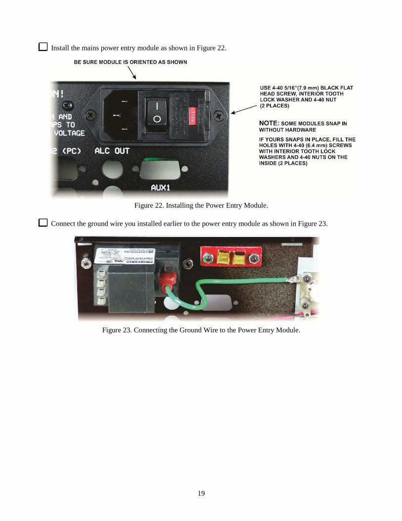
Install the mains power entry module as shown in Figure 22.
Figure 22. Installing the Power Entry Module.
Connect the ground wire you installed earlier to the power entry module as shown in Figure 23.
Figure 23. Connecting the Ground Wire to the Power Entry Module.
20
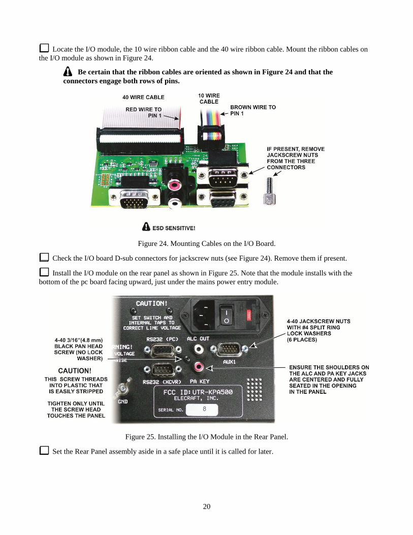
Locate the I/O module, the 10 wire ribbon cable and the 40 wire ribbon cable. Mount the ribbon cables on the I/O module as shown in Figure 24.
Be certain that the ribbon cables are oriented as shown in Figure 24 and that the connectors engage both rows of pins.
Figure 24. Mounting Cables on the I/O Board.
Check the I/O board D-sub connectors for jackscrew nuts (see Figure 24). Remove them if present.
Install the I/O module on the rear panel as shown in Figure 25. Note that the module installs with the bottom of the pc board facing upward, just under the mains power entry module.
Figure 25. Installing the I/O Module in the Rear Panel.
Set the Rear Panel assembly aside in a safe place until it is called for later.

21
RF Power Amplifier/Low Pass Filter (PA/LPF) Module
Unwrap the PA/LPF module. This module consists of two boards that have been pre-assembled, tested and aligned. Take care not to disturb or stress any of the inductors. Also, there are two screwdriver-adjusted potentiometers on the lower board. Do not disturb these adjustments. Place the PA/LPF module on your work table as shown in Figure 26. Be sure it is oriented as shown.
Figure 26. Placing the PA/LPF on the Work Table.
22
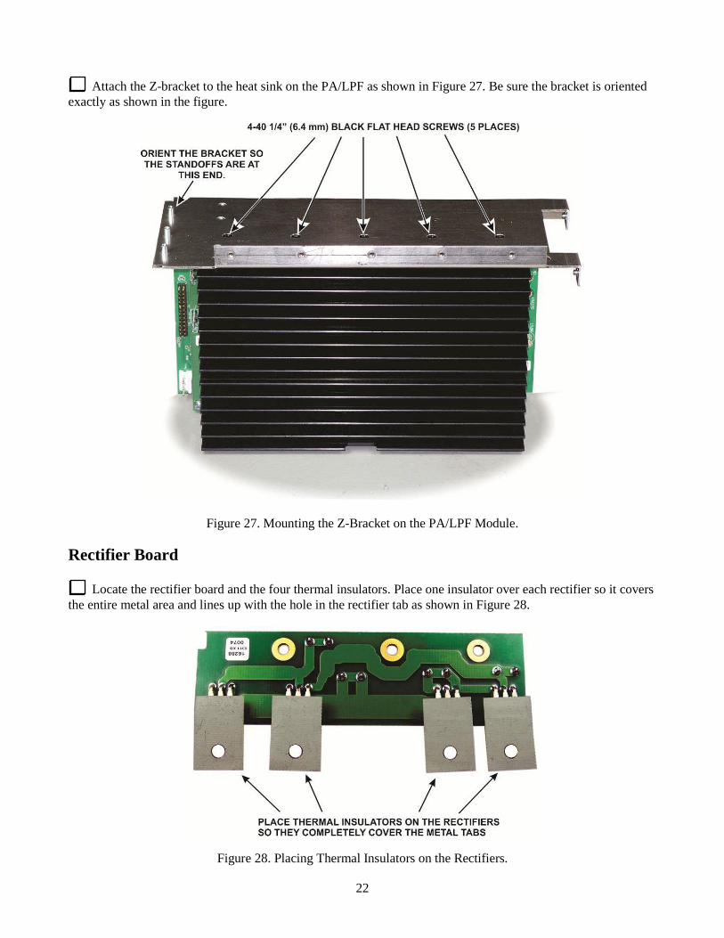
Attach the Z-bracket to the heat sink on the PA/LPF as shown in Figure 27. Be sure the bracket is oriented exactly as shown in the figure.
Figure 27. Mounting the Z-Bracket on the PA/LPF Module.
Rectifier Board
Locate the rectifier board and the four thermal insulators. Place one insulator over each rectifier so it covers the entire metal area and lines up with the hole in the rectifier tab as shown in Figure 28.
Figure 28. Placing Thermal Insulators on the Rectifiers.

23
Mount the rectifier board on the Z-bracket as shown in Figure 29. The three holes in the pc board mount on the three standoffs on the Z-bracket.
Figure 29. Rectifier Board on the Z-Bracket.
Use your DMM to check for shorts between the metal tab on each rectifier and the bare metal of the Z-bracket. The DMM should indicate whatever it normally shows when the probes are not touching.
Place the Z-bracket with the rectifier board and PA/LPF module attached on your work table with the heat sink down, then gently position the bottom cover assembly you completed earlier over it as shown in Figure 30. Locate and pull the gray wire attached to the power supply module to the rear and route it through the hole in the Z-bracket as shown. The connector is typically a very tight fit the first time it is passed through the hole.
Figure 30. Preparing to Install the Z-Bracket Assembly in the Bottom Cover.

24
Reposition the bottom cover assembly and attach it to the transformer support plate and Z-bracket as shown in Figure 31.
Figure 31. Installing the Z-Bracket and Transformer Support Plate in the Bottom Cover Assembly.
Locate the right side panel and remove any masking tape found on the inside (partially painted) surface.
Stand the unit on the left side panel and install the right side panel as shown in Figure 32. The weight of the PA/LPF module may flex the Z-bracket slightly. The unit will be somewhat top heavy in this position but it best protects the PA/LPF assembly toroids from accidentally being pushed down against the bottom cover until the side panel is in place. Install the screws that thread into the PA/LPF module heat sink first so you can easily make small adjustments, if needed, to align the holes for the remaining screws.
Figure 32. Mounting the Right Side Panel.
25
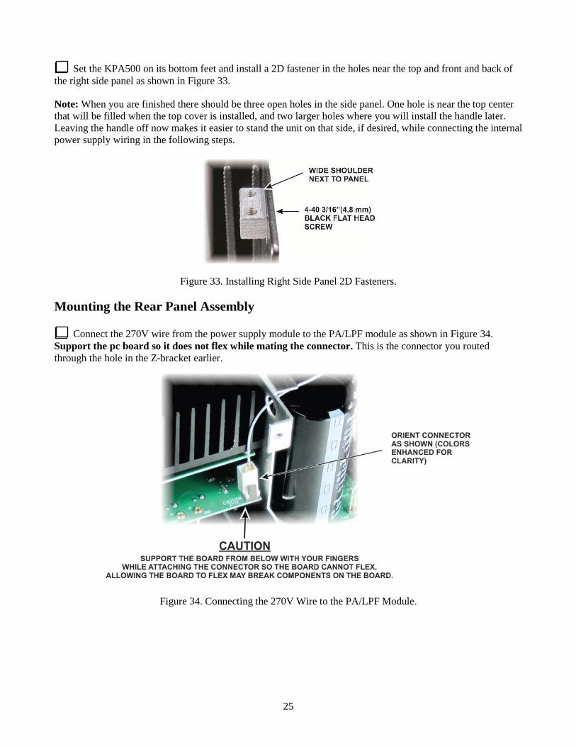
Set the KPA500 on its bottom feet and install a 2D fastener in the holes near the top and front and back of the right side panel as shown in Figure 33.
Note: When you are finished there should be three open holes in the side panel. One hole is near the top center that will be filled when the top cover is installed, and two larger holes where you will install the handle later. Leaving the handle off now makes it easier to stand the unit on that side, if desired, while connecting the internal power supply wiring in the following steps.
Figure 33. Installing Right Side Panel 2D Fasteners.
Mounting the Rear Panel Assembly
Connect the 270V wire from the power supply module to the PA/LPF module as shown in Figure 34. Support the pc board so it does not flex while mating the connector. This is the connector you routed through the hole in the Z-bracket earlier.
Figure 34. Connecting the 270V Wire to the PA/LPF Module.

26
Connect the cable from the interlock switch on the left side panel to the power supply module as shown in Figure 35.
Figure 35. Connecting the Interlock Cable to the Power Supply Module.
Temporarily route all the heavy wires connected to the power supply module toward the front so they will be out of the way for the next steps, then place the rear panel assembly directly behind the KPA500 chassis. It will stand upright, resting on the fan housing.
Connect the 10-wire ribbon cable to the power supply module as shown in Figure 36. Note the brown wire (pin 1) must go to the end of the connector nearest the KPA500 side panel. To do so it makes a 1/2 turn twist. Be certain the connector engages both rows of pins.
Figure 36. Connecting the 10-Wire Ribbon Cable to the Power Supply Module.

27
Connect the red/black twisted wire pair from the fan to the power supply module as shown in Figure 37. Note that although this is a three-pin connector, the connector on the pc board is wired so it may be plugged in either way.
Figure 37. Connecting the Fan Cable to the Power Supply Module.
Connect the RF INPUT coaxial cable and the RF OUTPUT twisted pair to the PA/LPF module as shown in Figure 38. The miniature (TMP type) coaxial connector is a friction fit. Insert the connector up to where it begins to widen to form the “ears” on either side.
When inserting the TMP connector, be sure the center pin is aligned in socket. Pressing hard with the center pin misaligned can damage the socket. If you ever need to remove this connector, always grab it by the metal ears, not by the coaxial cable.
Figure 38. Connecting the RF INPUT and RF OUTPUT Cables to the PA/LPF Module.
28
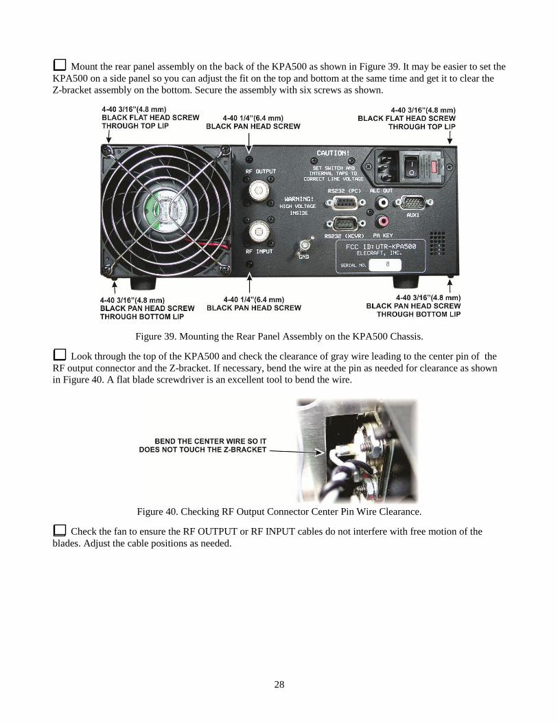
Mount the rear panel assembly on the back of the KPA500 as shown in Figure 39. It may be easier to set the KPA500 on a side panel so you can adjust the fit on the top and bottom at the same time and get it to clear the Z-bracket assembly on the bottom. Secure the assembly with six screws as shown.
Figure 39. Mounting the Rear Panel Assembly on the KPA500 Chassis.
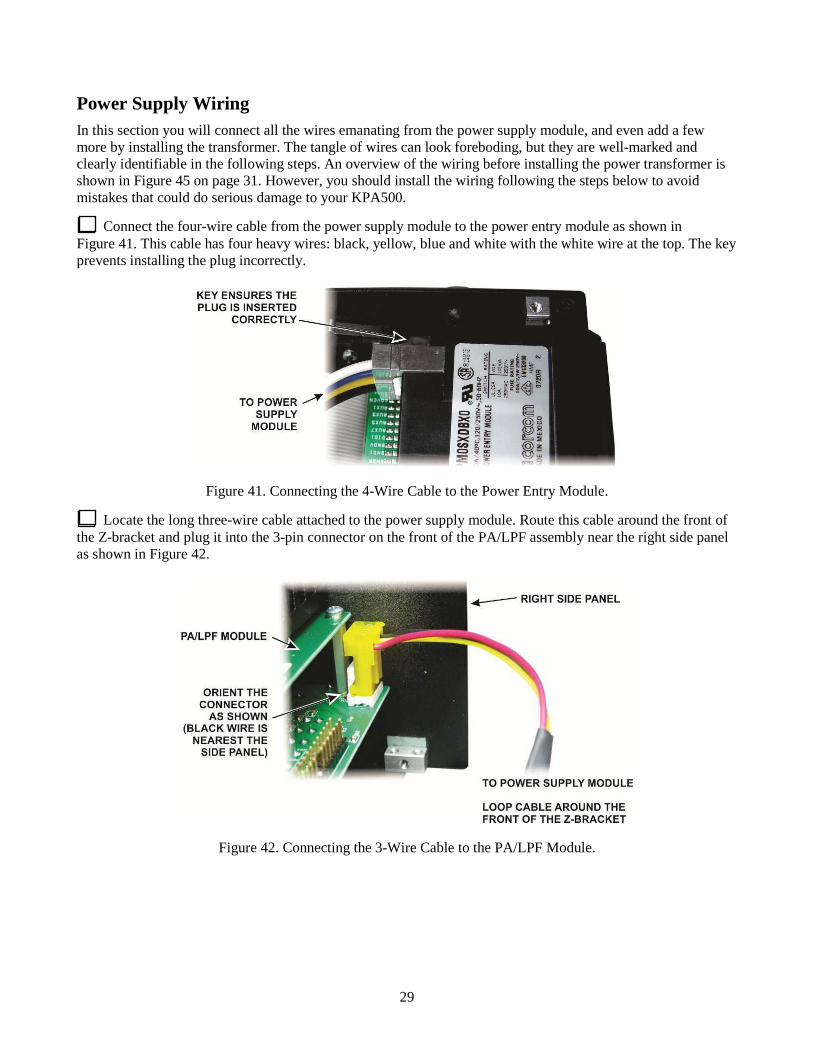
Look through the top of the KPA500 and check the clearance of gray wire leading to the center pin of the RF output connector and the Z-bracket. If necessary, bend the wire at the pin as needed for clearance as shown in Figure 40. A flat blade screwdriver is an excellent tool to bend the wire.
Figure 40. Checking RF Output Connector Center Pin Wire Clearance.
Check the fan to ensure the RF OUTPUT or RF INPUT cables do not interfere with free motion of the blades. Adjust the cable positions as needed.
29
Power Supply Wiring In this section you will connect all the wires emanating from the power supply module, and even add a few more by installing the transformer. The tangle of wires can look foreboding, but they are well-marked and clearly identifiable in the following steps. An overview of the wiring before installing the power transformer is shown in Figure 45 on page 31. However, you should install the wiring following the steps below to avoid mistakes that could do serious damage to your KPA500.
Connect the four-wire cable from the power supply module to the power entry module as shown in Figure 41. This cable has four heavy wires: black, yellow, blue and white with the white wire at the top. The key prevents installing the plug incorrectly.
Figure 41. Connecting the 4-Wire Cable to the Power Entry Module.
Locate the long three-wire cable attached to the power supply module. Route this cable around the front of the Z-bracket and plug it into the 3-pin connector on the front of the PA/LPF assembly near the right side panel as shown in Figure 42.
Figure 42. Connecting the 3-Wire Cable to the PA/LPF Module.

30
There are five wires remaining connected to the power supply module: two red, two black, and one white. One red and one black wire are longer than the others. Route the longer red and black wires around the end of the Z-bracket and connect them to the 60V and GND terminals on the PA/LPF Module as shown in Figure 43.
Figure 43. Connecting the 60V and GND Wires to the PA/LPF Module.
Connect the three remaining wires to the rectifier board mounted at the end of the Z-bracket as shown in Figure 44. Each spade connector is marked with the color of wire it receives. Route the black wire over the red and black wires passing around the end of the Z-bracket to keep them in place. They cannot be allowed to pass over the top of the Z-bracket or they will interfere with installing the top cover later.
Figure 44. Wiring the Rectifier Board.

31
Check your wiring against the overview in Figure 45. Note that the TAP spade connector on the rectifier board is not yet used, and there are five spade connectors on the power supply board (four hidden under the large ribbon cable) that are not yet used. They will be filled with leads from the power transformer installed in the following steps.
Figure 45. Overview of Power Supply Wiring Before Installing Power Transformer.
Temporarily remove the left side panel to provide room to install the power transformer. Remove the screws shown in Figure 14 plus the screw in the 2D fastener at the top rear corner. Do not remove the two screws holding the interlock switch (Figure 12). Unplug the interlock switch from the power supply board as you remove the panel.
32
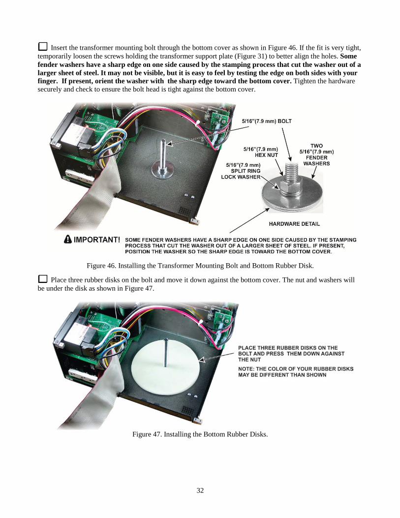
Insert the transformer mounting bolt through the bottom cover as shown in Figure 46. If the fit is very tight, temporarily loosen the screws holding the transformer support plate (Figure 31) to better align the holes. Some fender washers have a sharp edge on one side caused by the stamping process that cut the washer out of a larger sheet of steel. It may not be visible, but it is easy to feel by testing the edge on both sides with your finger. If present, orient the washer with the sharp edge toward the bottom cover. Tighten the hardware securely and check to ensure the bolt head is tight against the bottom cover.
Figure 46. Installing the Transformer Mounting Bolt and Bottom Rubber Disk.
Place three rubber disks on the bolt and move it down against the bottom cover. The nut and washers will be under the disk as shown in Figure 47.
Figure 47. Installing the Bottom Rubber Disks.
33
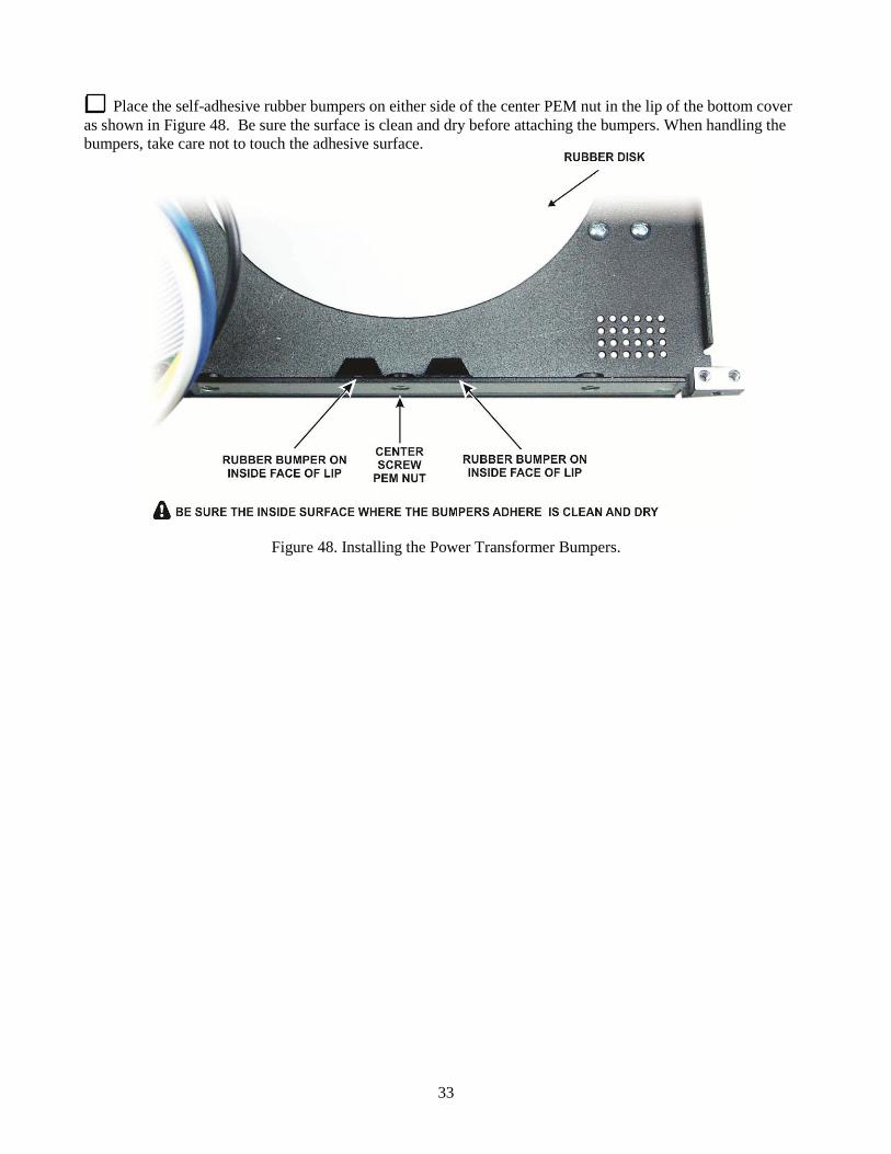
Place the self-adhesive rubber bumpers on either side of the center PEM nut in the lip of the bottom cover as shown in Figure 48. Be sure the surface is clean and dry before attaching the bumpers. When handling the bumpers, take care not to touch the adhesive surface.
Figure 48. Installing the Power Transformer Bumpers.

34
Move the transformer onto the edge of the bottom cover but do not place it over the bolt (see Figure 49). Lay the transformer flat with the leads exiting on the top and oriented so the orange lead will reach the terminal as shown. Take care not to dislodge the rubber bumpers you installed in the previous step. Connect the orange lead to the power supply module as shown.
Figure 49. Connecting the Orange Transformer Wire to the Power Supply Module.
Carefully lift the transformer onto the bolt without pulling the orange lead loose. As you set it down, be sure you don’t have wires trapped between the transformer and the Z-Bracket and press it toward the Z-Bracket so it clears the bumpers as shown in Figure 50. Note that the bolt may not be exactly centered in the opening in the middle of the transformer. That is normal.
Figure 50. Transformer Bumpers.

35
Orient the transformer as shown in Figure 51, taking care not to dislodge the bumpers. Add the second rubber disk and metal disk as shown. Orient the metal disk so the center depression goes down into the center of the transformer. Add the Belleville washer and secure the assembly with the Nylock nut. Tighten the nut enough to hold the hardware in place (you will tighten the nut further later).
IMPORTANT: The Belleville washer is not a flat washer. It is slightly conical shaped and acts as a spring. When properly installed the area around the center hole under the nut will be slightly higher than the outer edges. The nut bearing down on the washer will tend to flatten it, helping to hold the transformer securely. The conical shape is very subtle. To determine the correct orientation, place the washer on a hard flat surface and press on the edge. If it wobbles slightly, the washer is upside down. If pressing the edge causes no wobble, it is right side up. Be sure to install the washer right side up on the top metal disk.
Figure 51. Mounting the Power Transformer.

36
The transformer primary winding connections exit the transformer in a white sleeve. Connect them to the power supply module board as shown in Figure 52.
Figure 52. Connecting the Transformer Primary Windings to the Power Supply Module.
Replace the left side panel using the screws you removed earlier. Be sure to reconnect the interlock switch to the power supply module (see Figure 35 on page 26) and ensure the interlock switch cable is not trapped between the side panel and the heat spreader.
Stand the KPA500 on the left side and loosen the bolt and Nylock nut slightly so that the weight of the transformer bears on the rubber bumpers. Be sure the wide ribbon cable is not caught between the bumpers and the transformer. Tighten the bolt and Nylock nut just until the transformer no longer moves when pressed against the bottom, and then turn the nut between one and two turns further. This will result in about 55 in-pounds of torque on the nut and bolt. If you have a torque wrench, you may use it, but it is not necessary.
Set the KPA500 on its bottom feet. You should now have three loose transformer wires remaining. These are taps that are used to compensate for variation in your local mains voltage as described in your Owner’s Manual. The active tap is connected to the rectifier board and the two unused taps are connected to the terminals on the rear panel to keep them out of the way and to avoid short circuits. Connect them as shown in Figure 53 until you have completed assembling your KPA500.
Figure 53. Connecting Transformer Taps.

37
Two cable ties are provided to dress the long wires that pass over the transformer. These ties are supplied to produce a neat arrangement of the wires. They are not required for any safety or operational reason. If you have not worked with this type of cable tie before, Figure 54 shows the correct way to install them. Install the ties as shown in Figure 55. After pulling each tie tightly around the wires, cut off the excess where it exits the locking head. Take care to ensure the yellow, green and red wires can be attached either to the tap terminal on the rectifier module or to the parking terminals as shown in the figure.
Figure 54. Cable Tie.
Figure 55. Installing Cable Ties.

38
Front Panel Assembly
Locate the front panel and remove any masking tape found on the inside (partially painted) surface.
Install the standoffs in the inside of the front panel as shown in Figure 56. Include the plastic bezel on the front held by the four 2-56 screws.
Figure 56. Installing the Front Panel Standoffs and Bezel.
Remove the front panel board from its ESD-safe envelope. Take care not to disturb the alignment of the LEDs. Install the single square and 18 rectangular key caps as shown in Figure 57. The key caps simply push onto the shafts of the switches. Be sure you install the rectangular caps horizontally so they will fit through the openings in the front panel sheet metal.
Figure 57. Installing Key Caps on Front Panel Board.

39
Place the front panel sheet metal over the front panel pc board so that all the key caps and LEDs pass through the openings and the pc board rests against all of the standoffs. If you have difficulty, look closely at the LEDs. One slightly out of alignment will hit the edge of the opening in the sheet metal. If needed, carefully adjust the position of the LEDs.
Secure the front panel board to the standoffs as shown in Figure 58.
Figure 58. Installing the Front Panel Board.
Inspect the rows of LEDs on the front panel. If any LEDs are out of line , straighten them by running your finger or fingernail along them, pressing the LEDs against the opposite side of the opening. Optionally you can straighten the LEDs by pressing a straight edge (such as a rule) against them, pressing them against the opposite side of the opening.

40
Place the front panel assembly in front of the KPA500 and connect the ribbon cables as shown in Figure 59. The wide cable may be longer than shown here.
Figure 59. Connecting the Front Panel Assembly to the KPA500.

41
Mount the front panel assembly on the KPA500 as shown in Figure 60. If the wide ribbon cable is longer than necessary loop it back and forth behind the front panel board in the space directly in front of the power transformer as shown in Figure 61. The front panel fits between the side panels. If the fit is too tight, loosen some of the screws near the front on the side panels, particularly on left side panel since it is less rigidly held in place. Be sure to tighten all the screws after the assembly is in place.
CAUTION
The weight of the transformer can make the unit unstable if placed on its right side. Ensure you have a good grip when handling the KPA500 and either stand it on the left side (with the feet) or place it upside down to access the bottom screws.
Figure 60. Mounting the Front Panel Assembly on the KPA500.
Figure 61. Routing Long Ribbon Cable.
42
Top Cover and Side Handle
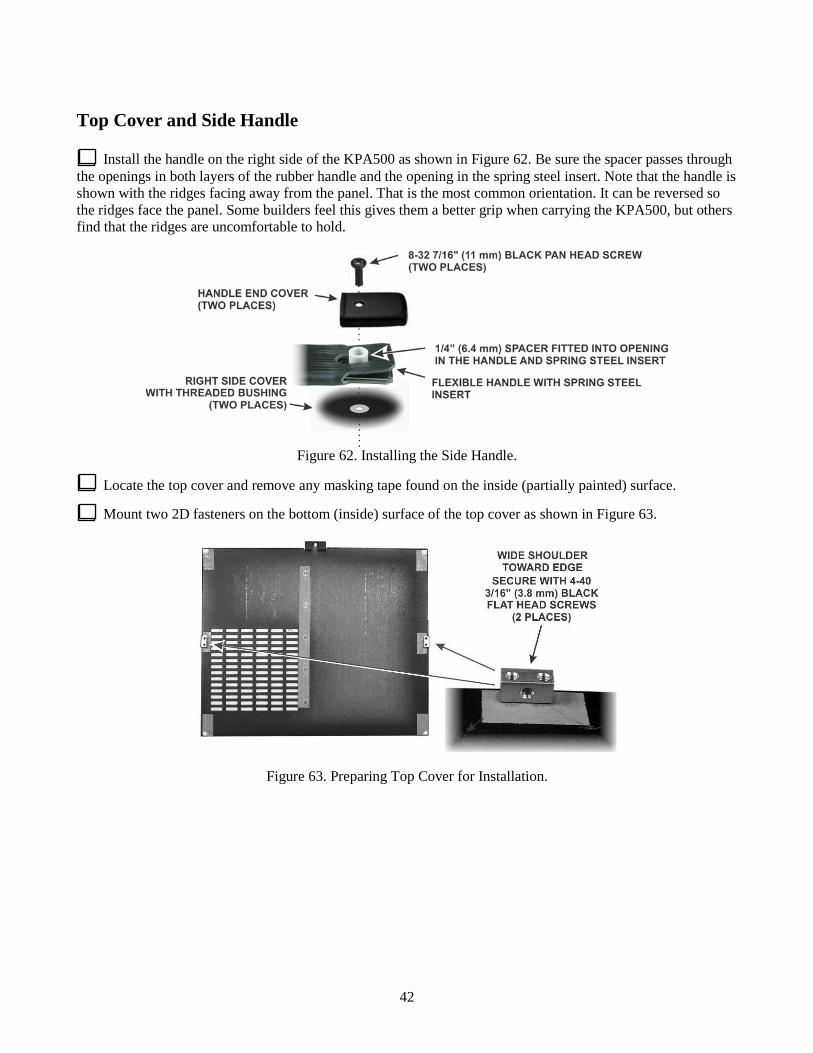
Install the handle on the right side of the KPA500 as shown in Figure 62. Be sure the spacer passes through the openings in both layers of the rubber handle and the opening in the spring steel insert. Note that the handle is shown with the ridges facing away from the panel. That is the most common orientation. It can be reversed so the ridges face the panel. Some builders feel this gives them a better grip when carrying the KPA500, but others find that the ridges are uncomfortable to hold.
Figure 62. Installing the Side Handle.
Locate the top cover and remove any masking tape found on the inside (partially painted) surface.
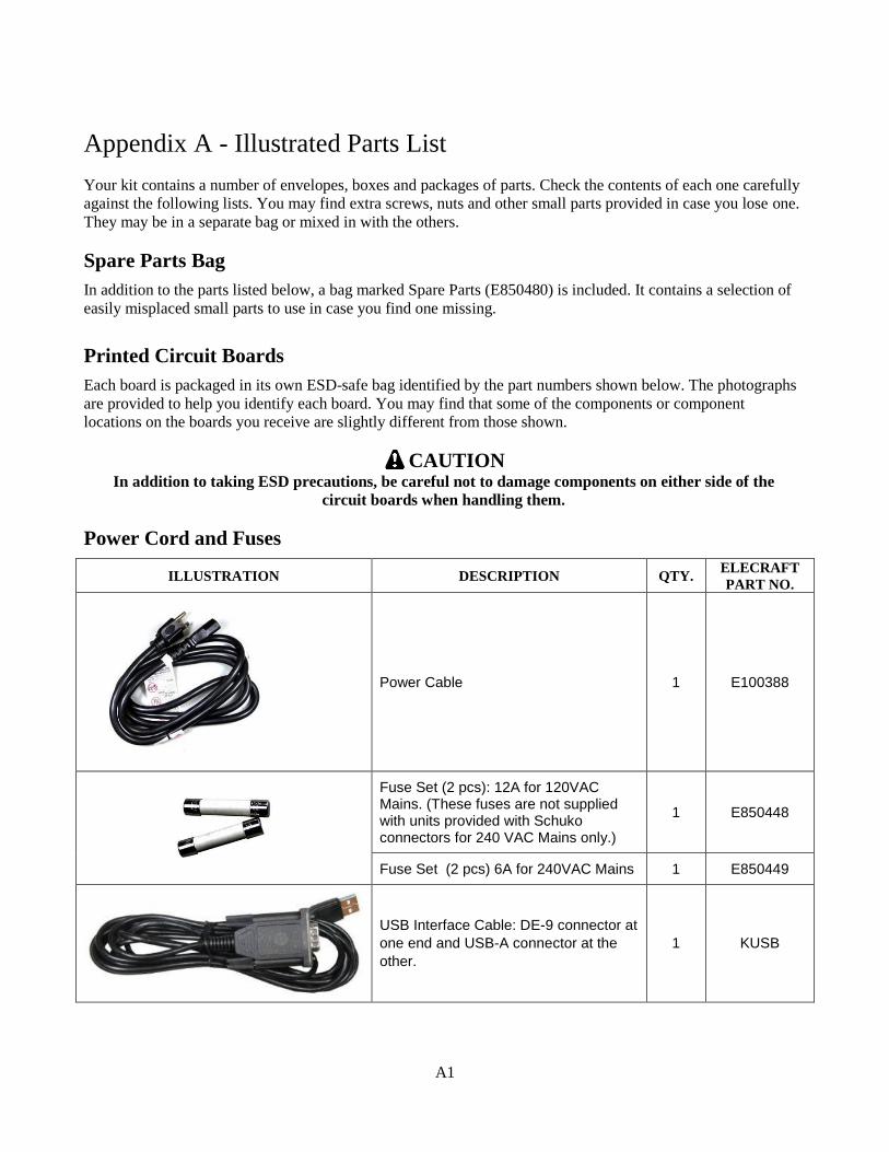
Mount two 2D fasteners on the bottom (inside) surface of the top cover as shown in Figure 63.
Figure 63. Preparing Top Cover for Installation.

43
You will install the top cover in the following step. If you are going to immediately set up your KPA500 for operation, turn to Mains Voltage Settings in your Owner’s manual first since you may need to remove the top cover to adjust the transformer taps.
Place the top cover on the KPA500, slipping the tab under the top lip on the rear panel. You may need to loosen some screws on the side, front and rear panels again to adjust the fit. Fasten the top cover as shown in Figure 64.
Figure 64. Top Cover Installation.
That completes the assembly of your KPA500 Kit. Turn to your Owner’s Manual for installation and operating instructions before you attempt to apply power or use your KPA500.
IMPORTANT! You must install the proper fuses in the rear-panel fuse block before the KPA500 will operate. See the Mains Voltage Settings in your Owner’s manual to install the fuses and select the correct transformer tap.
A1
Appendix A - Illustrated Parts List
Your kit contains a number of envelopes, boxes and packages of parts. Check the contents of each one carefully
against the following lists. You may find extra screws, nuts and other small parts provided in case you lose one.
They may be in a separate bag or mixed in with the others.
Spare Parts Bag
In addition to the parts listed below, a bag marked Spare Parts (E850480) is included. It contains a selection of
easily misplaced small parts to use in case you find one missing.
Printed Circuit Boards
Each board is packaged in its own ESD-safe bag identified by the part numbers shown below. The photographs
are provided to help you identify each board. You may find that some of the components or component
locations on the boards you receive are slightly different from those shown.
CAUTION In addition to taking ESD precautions, be careful not to damage components on either side of the
circuit boards when handling them.
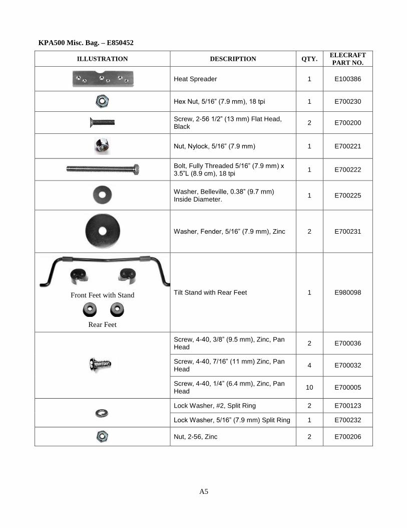
Power Cord and Fuses
ILLUSTRATION DESCRIPTION QTY. ELECRAFT
PART NO.
Power Cable 1 E100388
Fuse Set (2 pcs): 12A for 120VAC Mains. (These fuses are not supplied with units provided with Schuko connectors for 240 VAC Mains only.)
1 E850448
Fuse Set (2 pcs) 6A for 240VAC Mains 1 E850449
USB Interface Cable: DE-9 connector at one end and USB-A connector at the other.
1 KUSB

A2
KPA500 Core Assembly – E850455
ILLUSTRATION DESCRIPTION QTY. ELECRAFT
PART NO.
PA Key Cable 1 E100416
Z bracket 1 E100385
KPA500 Front Panel – E850470
ILLUSTRATION DESCRIPTION QTY. ELECRAFT
PART NO.
Front Panel Metal 1 E100380
KPA500 Rear Panel – E850469
ILLUSTRATION DESCRIPTION QTY. ELECRAFT
PART NO.
Rear Panel Metal 1 E100381
KPA500 Side Panels – E850468
ILLUSTRATION DESCRIPTION QTY. ELECRAFT
PART NO.
Left Side Panel 1 E100379
Right Side Panel 1 E100378

A3
KPA500 Bottom Cover Assembly – E850472
ILLUSTRATION DESCRIPTION QTY. ELECRAFT
PART NO.
Bottom Cover 1 E100382
KPA500 Top Cover Assembly – E850473
ILLUSTRATION DESCRIPTION QTY. ELECRAFT
PART NO.
Top Cover 1 E100383
KPA500 Transformer Support – E850471
ILLUSTRATION DESCRIPTION QTY. ELECRAFT
PART NO.
Transformer Support 1 E100384
KPA500 Carry Handle Bag – E850453
ILLUSTRATION DESCRIPTION QTY. ELECRAFT
PART NO.
Screw, 8-32, 7/16” (11 mm), Pan Head, Black 2 E700356
Spacer, 1/4" (6.4 mm) Long 2 E700273
Handle with 2 End Caps 1 E980115

A4
KPA500 Front Panel Bezel and Serial Number – E850461
ILLUSTRATION DESCRIPTION QTY. ELECRAFT
PART NO.
Serial Number Label 1 E850450
Bezel (Leave in protective plastic wrapping until instructed to avoid scratches.)
1 E850461
KPA500 Rear Panel Bag – E850454
ILLUSTRATION DESCRIPTION QTY. ELECRAFT
PART NO.
Power Entry Module (Corcom) 1 E620184
10 Wire Ribbon Cable 1 E850479
Fan Guard 1 E980177
Fan Assembly 1 E850415
40 Wire Ribbon Cable 1 E850478
A5
KPA500 Misc. Bag. – E850452
ILLUSTRATION DESCRIPTION QTY. ELECRAFT
PART NO.
Heat Spreader 1 E100386
Hex Nut, 5/16” (7.9 mm), 18 tpi 1 E700230
Screw, 2-56 1/2” (13 mm) Flat Head, Black 2 E700200
Nut, Nylock, 5/16” (7.9 mm) 1 E700221
Bolt, Fully Threaded 5/16” (7.9 mm) x 3.5”L (8.9 cm), 18 tpi 1 E700222
Washer, Belleville, 0.38” (9.7 mm) Inside Diameter. 1 E700225
Washer, Fender, 5/16” (7.9 mm), Zinc 2 E700231
Front Feet with Stand
Rear Feet
Tilt Stand with Rear Feet 1 E980098
Screw, 4-40, 3/8” (9.5 mm), Zinc, Pan Head 2 E700036
Screw, 4-40, 7/16” (11 mm) Zinc, Pan Head 4 E700032
Screw, 4-40, 1/4” (6.4 mm), Zinc, Pan Head 10 E700005
Lock Washer, #2, Split Ring 2 E700123
Lock Washer, 5/16” (7.9 mm) Split Ring 1 E700232
Nut, 2-56, Zinc 2 E700206

A6
Screw, 4-40, 3/8” (9.5 mm) Pan Head, Black 3 E700008
Screw, 4-40, 1/4" (6.4 mm) Pan Head, Black 4 E700009
Screw, 4-40, 3/16” (4.8 mm) Pan Head, Black 15 E700015
Nut, 4-40, with Captive Star Washer 4 E700169
Grommet Bumper, 7/16” (11 mm) Round, Black 4 E980141
Shoulder Enhanced in Image Shoulder Washer, 4-40 Black 5 E700001
Thermal Insulator 4-40, Adhesive 5 E700002
Rubber Bumper, Self Adhesive 2 E700024
2D Fastener 10 E100078
Screw, 6-32,1/4” (6.4 mm) Flat Head, Black (Anodized) 10 E700186
Screw, 4-40, 5/16” (7.9 mm) Flat Head, Black 10 E700027
Screw, 4-40, 1/4" (6.4 mm) Flat Head, Black 5 E700082
Screw, 4-40, 3/16” (4.8 mm) Flat Head, Black 21 E700025
Lock Washer, #4, Interior Tooth 17 E700010
Cable Tie, 3.9” (10 cm) 2 E980145
Interlock Switch Assy 1 E850417

A7
KPA500 Front Panel Envelope – E850477
ILLUSTRATION DESCRIPTION QTY. ELECRAFT
PART NO.
Keycap, Square 1 E980164
Keycap, Rectangular 18 E980000
Standoff, 2-56, 5/16” (7.9 mm) Long 4 E700122
Lock Washer, #2, Split Ring 4 E700123
Screw, 4-40, 3/16” (4.8 mm) , Black, Flat Head 6 E700025
Standoff, 4-40, 5/16” (7.9 mm) Long 6 E700121
Screw, 2-56, 1/4" (6.4 mm) Black, Pan Head 8 E700124
Lock Washer #4, Split Ring 12 E700004
Screw, 4-40, 3/16” (4.8 mm) Black, Pan Head 6 E700015
KPA500 Rear Panel Envelope – E850475
ILLUSTRATION DESCRIPTION QTY. ELECRAFT
PART NO.
Black Pan Head Screw (Typ.)
Screw, 4-40, 3/16”, ( 4.8 mm) Black, Pan Head 1 E700015
Screw, 6-32, 2” (5.1 cm), Black, Pan Head 4 E700205
Screw, 4-40, 3/8”( 9.5 mm) , Black, Pan Head 10 E700008
Screw, 8-32, 1/2" (13 mm), Zinc, Pan Head 1 E700192
Screw, 4-40, 5/16 (7.9 mm) ”, Black, Flat Head 2 E700027
Wing Nut, 8-32, Stainless Steel 1 E700193
A8
ILLUSTRATION DESCRIPTION QTY. ELECRAFT
PART NO.
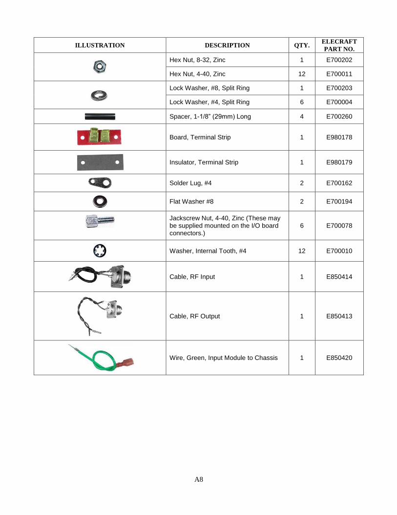
Hex Nut, 8-32, Zinc 1 E700202
Hex Nut, 4-40, Zinc 12 E700011
Lock Washer, #8, Split Ring 1 E700203
Lock Washer, #4, Split Ring 6 E700004
Spacer, 1-1/8” (29mm) Long 4 E700260
Board, Terminal Strip 1 E980178
Insulator, Terminal Strip 1 E980179
Solder Lug, #4 2 E700162
Flat Washer #8 2 E700194
Jackscrew Nut, 4-40, Zinc (These may be supplied mounted on the I/O board connectors.)
6 E700078
Washer, Internal Tooth, #4 12 E700010
Cable, RF Input 1 E850414
Cable, RF Output 1 E850413
Wire, Green, Input Module to Chassis 1 E850420
A9
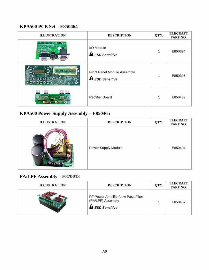
KPA500 PCB Set – E850464
ILLUSTRATION DESCRIPTION QTY. ELECRAFT
PART NO.
I/O Module
ESD Sensitive 1 E850394
Front Panel Module Assembly
ESD Sensitive 1 E850395
Rectifier Board 1 E850439
KPA500 Power Supply Assembly – E850465
ILLUSTRATION DESCRIPTION QTY. ELECRAFT
PART NO.
Power Supply Module 1 E850404
PA/LPF Assembly – E870018
ILLUSTRATION DESCRIPTION QTY. ELECRAFT
PART NO.
RF Power Amplifier/Low Pass Filter (PA/LPF) Assembly
ESD Sensitive 1 E850467

A10
KPA500 Transformer Assembly – E850466
ILLUSTRATION DESCRIPTION QTY. ELECRAFT
PART NO.
Power Transformer
Rubber Disks Metal Disk
Transformer Assembly w/1 Metal and 4 Rubber Disks
Note: The Rubber Disks may be a different color than shown
1 E850416