electric and magnetic sensors and actuators (chapter 5, part a)
TRANSCRIPT
Electric and magnetic sensors and actuatorsElectric and magnetic sensors and actuators
(chapter 5, Part A)(chapter 5, Part A)

IntroductionIntroduction
Broadest by far of all other classes In numbers and types of sensors In variety within each type.
Reasons: Sensor exploits the electrical properties of materials Many electrical effects The requisite output is almost always electrical
Some electrical/electromagnetic sensors not discussed here: (Thermocouples, optical, ultrasonic sensors etc.)

IntroductionIntroduction
Most actuators are either electrical or, more commonly, magnetic.
This is particularly true of actuators that need to provide considerable power.
We will limit ourselves here to the following types of sensors and actuators:
Most actuators are either electrical or, more commonly, magnetic.
This is particularly true of actuators that need to provide considerable power.
We will limit ourselves here to the following types of sensors and actuators:

IntroductionIntroduction Sensors and actuators based on electric/electrostatic
principles. include MEMS (micro-electro-mechanical sensors), which are
most often based on electrostatic forces capacitive sensors (proximity, distance, level, material
properties, humidity and other quantities such as force, acceleration and pressure may be sensed) and related field sensors.
Magnetic sensors and actuators based on static and quasi-static magnetic fields.
motors and valves for actuation, magnetic field sensors (hall element sensors, inductive sensors
for position, displacement, proximity and others), magnetostrictive sensors and actuators and more.
Sensors and actuators based on electric/electrostatic principles.
include MEMS (micro-electro-mechanical sensors), which are most often based on electrostatic forces
capacitive sensors (proximity, distance, level, material properties, humidity and other quantities such as force, acceleration and pressure may be sensed) and related field sensors.
Magnetic sensors and actuators based on static and quasi-static magnetic fields.
motors and valves for actuation, magnetic field sensors (hall element sensors, inductive sensors
for position, displacement, proximity and others), magnetostrictive sensors and actuators and more.

DefinitionsDefinitions Electric field: Force per unit charge
exists in the presence of charges or charged bodies. electric field may be static when charges do not move or
move at constant velocity time dependent if charges accelerate and/or decelerate.
Moving charges in conducting media or in space cause currents
Currents produce magnetic fields. Magnetic fields are either static – when currents are
constant (dc) or: Time dependent when currents vary in time.
Electric field: Force per unit charge exists in the presence of charges or charged bodies. electric field may be static when charges do not move or
move at constant velocity time dependent if charges accelerate and/or decelerate.
Moving charges in conducting media or in space cause currents
Currents produce magnetic fields. Magnetic fields are either static – when currents are
constant (dc) or: Time dependent when currents vary in time.

Definitions (cont.)Definitions (cont.)
If currents vary in time: both an electric and a related magnetic field are established.
This is called the electromagnetic field. Electromagnetic field implies that both an electric and a
magnetic field exists. It is OK to call all electric and magnetic fields by that
name since, for example an electrostatic field may be viewed as a time independent electromagnetic field with zero magnetic field.
All fields described by Maxwell’s equations - will not be discussed here

Sensing strategiesSensing strategies
Anything that influences one of these quantities may be sensed through the electromagnetic field.
Electromagnetic actuators are based on one of the two basic forces; the electric force (best understood as the attraction
between opposite polarity charges or repulsion between like polarity charges)
the magnetic force. The latter is the attraction of current carrying conductors with currents in the same directions or repulsion of current carrying conductors with currents in opposite directions.

Electric Field – Capacitive Sensors and Actuators
Electric Field – Capacitive Sensors and Actuators
Electric field sensors and actuators operate on the physical principles of the electric field
and its effects (capacitance, charge, stored energy) The primary type: capacitive device.
Some sensors such as charge sensors are better explained in terms of the electric field
On the whole, discussion of capacitance and its use in sensing and actuation covers most aspects necessary for a thorough understanding of these types of sensors without the need to study the intricacies of the electric field behavior.

CapacitanceCapacitance
Capacitance: the ratio between charge and potential of a body
Measured in coulombs/volt. This unit is called the farad [F].
Capacitance is only defined for two conducting bodies, across which the potential difference is connected.
Capacitance: the ratio between charge and potential of a body
Measured in coulombs/volt. This unit is called the farad [F].
Capacitance is only defined for two conducting bodies, across which the potential difference is connected.
C =
Q
V
C
V

Capacitance (cont.)Capacitance (cont.)
Body B is charged by the battery to a positive charge Q and body A to an equal but negative charge –Q.
Any two conducting bodies, regardless of size and distance between them have a capacitance.
Body B is charged by the battery to a positive charge Q and body A to an equal but negative charge –Q.
Any two conducting bodies, regardless of size and distance between them have a capacitance.

Parallel plate capacitorParallel plate capacitor
Parallel plate capacitor: Assumes d is small, 0 is the permittivity of vacuum, r the relative permittivity (dielectric
constant) of the medium between plates, S the area of the plates and d the distance between the plates. 0 is a constant equal to 8.854x10 F/m r is the ratio between the permittivity of
the medium to that of free space. available as part of the electrical
properties of materials.
C =
0
rS
d
FC =
0
rS
d
F

Parallel plate capacitor (cont.)Parallel plate capacitor (cont.)
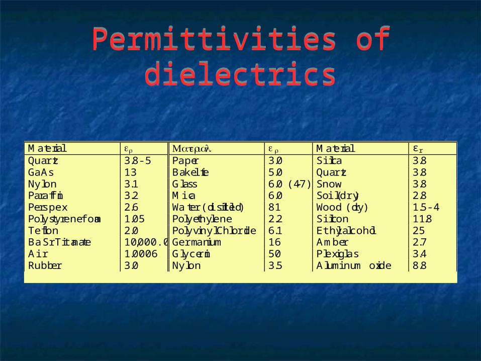
Permittivities of dielectricsPermittivities of dielectrics
Material r Material r Material ε r
Quartz 3.8-5 Paper 3.0 Silica 3.8GaAs 13 Bakelite 5.0 Quartz 3.8Nylon 3.1 Glass 6.0 (4-7) Snow 3.8Paraffin 3.2 Mica 6.0 Soil (dry) 2.8Perspex 2.6 Water (distilled) 81 Wood (dry) 1.5-4Polystyrene foam 1.05 Polyethylene 2.2 Silicon 11.8Teflon 2.0 Polyvinyl Chloride 6.1 Ethyl alcohol 25Ba Sr Titanate 10,000.0 Germanium 16 Amber 2.7Air 1.0006 Glycerin 50 Plexiglas 3.4Rubber 3.0 Nylon 3.5 Aluminum oxide 8.8

Capacitors - cont.Capacitors - cont.
Any of the quantities in Eq. (2) affect the capacitance
Changes in these can be sensed. A wide range of stimuli including
displacement and anything else that can cause displacement (pressure, force), proximity, permittivity (for example in moisture sensors)
a myriad of other effects are related to capacitance.

Capacitors - cont.Capacitors - cont.
Eq. (2) describes a very specific device Was obtained by assuming that the electric field
between the two plates does not leak (fringes) outside the space between the plates.
In the more general case, when d is not small, or: Plates are arranged in a different configuration
we cannot calculate the capacitance directly but we can still write the following:
C = α 0
, r
, S , / d

Capacitors - examplesCapacitors - examples

Capacitive position sensorsCapacitive position sensors
Capacitive position, proximity and displacement sensors
Capacitive position, proximity and displacement sensors
Position and displacement can be sensed in three fundamental ways:
(1) By allowing a plate to move relative to the other (figure a).
A number of configurations are shown next: the sensor is made of a single plate while the second
plate is a conductor to which the distance (proximity) is sensed.
Requires connection to the sensed object

Position and displacement sensing
Position and displacement sensing

Position sensing relative to a fixed conductor
Position sensing relative to a fixed conductor
A schematic position sensor is shown in below One plate is fixed while the other is pushed by the moving device. The position of the moving device causes a change in position of
the dielectric and this changes the capacitance. C Capacitance is inversely proportional to the motion and As long as the distances sensed are small, the output is linear.

Sensing by moving the dielectricSensing by moving the dielectric
(2) The plates remain fixed but the dielectric moves in or out as in Figure b.
Practical for some applications. For example, the dielectric may be connected to a float
which then senses the fluid level or It may be pushed by a device to sense end of travel or
position. Advantages: linearity, range of motion is rather large and
can equal the width of the capacitor.
Sensing by moving the whole capacitor
Sensing by moving the whole capacitor
(3) by keeping the plates fixed as in Figure c and sensing the distance to a surface.
This is a more practical arrangement since the sensor is self contained and requires no mechanical contact to sense distance or position.
Most capacitive sensors are a variation of this arrangement
(3) by keeping the plates fixed as in Figure c and sensing the distance to a surface.
This is a more practical arrangement since the sensor is self contained and requires no mechanical contact to sense distance or position.
Most capacitive sensors are a variation of this arrangement

Practical proximity sensorsPractical proximity sensors
Typically, a hollow cylindrical conductor forms one plate of the sensor as in Figure 5.7.
The second plate of the sensor is a disk at the lower opening of the cylinder.
The whole structure may be enclosed with an outer conducting shield or may be encased in a cylindrical plastic enclosure. The capacitance of the device is C0 based on dimensions, materials and structure.

Structure of a practical proximity sensor
Structure of a practical proximity sensor

Proximity sensors - cont.Proximity sensors - cont.
When any material is present, effective permittivity seen by the sensor and capacitances increases - indicates distance
Senses distances to conducting or nonconducting bodies of any shape but output is not linear. the smaller the sensed distance d, the larger the
sensitivity of the sensor. dimensions of the sensor makes a big difference in span
and sensitivity. large diameter sensors will have a larger span while
small diameter sensor will have a shorter span.

Proximity sensors - cont.Proximity sensors - cont.
Other methods: Example: Two fixed plates and one moving
plate. When the plate is midway, its potential is zero
since C1=C2. As the plate moves up, its potential becomes positive. When it moves down it is negative. More linear than the previous sensors Motion must be small or the capacitances will be very
small and difficult to measure.

Position sensorPosition sensor

Other position, displacement, proximity sensors:
Other position, displacement, proximity sensors:
Rotary (angular) position sensors Linear displacement sensors:
Integrated comb-like sensors Sideways sliding plates Plunger type sensors
Others
Rotary (angular) position sensors Linear displacement sensors:
Integrated comb-like sensors Sideways sliding plates Plunger type sensors
Others
Rotary position sensorRotary position sensor

Other configurations for linear displacement sensors
Other configurations for linear displacement sensors

Commercial capacitive sensorsCommercial capacitive sensors

Capacitive fluid level sensorsCapacitive fluid level sensors
Fluid level: may be sensed by any of the position or proximity
sensors discussed in the previous paragraph by sensing the position of the fluid surface directly or through a float which then can change the
capacitance of a linear capacitor or a rotary capacitor. There is however another method which is linear
but can have a very large range. The method is shown next:

Co-axial fluid level sensorCo-axial fluid level sensor

Co-axial fluid level sensorCo-axial fluid level sensor A coaxial capacitor is made of
two concentric cylinders establishing a capacitance C0.
Capacitance of a coaxial capacitor of length L, inner radius a and outer radius b is:
If the fluid fills the capacitor to a height h, capacitance is:
A coaxial capacitor is made of two concentric cylinders establishing a capacitance C0.
Capacitance of a coaxial capacitor of length L, inner radius a and outer radius b is:
If the fluid fills the capacitor to a height h, capacitance is:
C0
=
2 π 0
L
ln ( b / a )
F
C0
=
2 π 0
ln ( b / a )
h r
+ L − h F

Co-axial fluid level sensorCo-axial fluid level sensor
Capacitance is linear with respect to h from h=0 to h=L
Capacitive fuel gages are of this type but the idea can be used for any fluid that is nonconductive such as oils.
Capacitance is linear with respect to h from h=0 to h=L
Capacitive fuel gages are of this type but the idea can be used for any fluid that is nonconductive such as oils.

Capacitive sensors - commentsCapacitive sensors - comments
Simple and rugged sensors Useful in many other applications
(pressure, acoustic sensors, etc.) Capacitances are small and changes in
capacitance even smaller. Require special methods of transduction. Often part of LC oscillator (measure freq.) Others use an ac source (measure imped.)
Simple and rugged sensors Useful in many other applications
(pressure, acoustic sensors, etc.) Capacitances are small and changes in
capacitance even smaller. Require special methods of transduction. Often part of LC oscillator (measure freq.) Others use an ac source (measure imped.)

Capacitive actuatorsCapacitive actuators
Capacitive actuation is simple: Potential is connected across the two
plates of a capacitor Plates acquire opposite charges. These charges attract each other based
on Coulomb’s law Force tends to pull the plates together.
Capacitive actuation is simple: Potential is connected across the two
plates of a capacitor Plates acquire opposite charges. These charges attract each other based
on Coulomb’s law Force tends to pull the plates together.

Capacitive actuatorsCapacitive actuators
Mechanical motion of the plates is possible - constitutes actuation
In a parallel plate capacitor the force is:
For other configurations: no exact relation but:
Same general behavior
Mechanical motion of the plates is possible - constitutes actuation
In a parallel plate capacitor the force is:
For other configurations: no exact relation but:
Same general behavior
F =
C V
2
d
=
0
rS V
d

Capacitive actuatorsCapacitive actuators
Force developed is proportional to:
Capacitance: Distance between plates: Potential across plates Forces are typically small (
is very small)
Force developed is proportional to:
Capacitance: Distance between plates: Potential across plates Forces are typically small (
is very small)
F =
C V
2
d
=
0
rS V
d

Basic capacitive actuatorBasic capacitive actuator
An electrostatic actuator (electrostatic speaker)Upper plate is attracted or repelled by lower, fixed
plateMotion may be used for positioning or for voice
reproduction
An electrostatic actuator (electrostatic speaker)Upper plate is attracted or repelled by lower, fixed
plateMotion may be used for positioning or for voice
reproduction

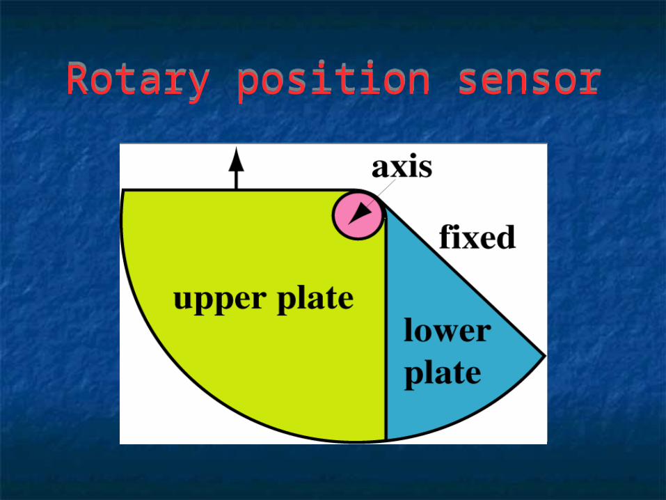
Angular capacitive actuatorAngular capacitive actuator
Upper plate moves relative to lower plate Force proportional to position (capacitance
changes) Useful for small, low force motion.
Upper plate moves relative to lower plate Force proportional to position (capacitance
changes) Useful for small, low force motion.

Electrostatic actuators - comments
Electrostatic actuators - comments
Motion is usually small (except loudspeakers)
Voltages are high Force is low Usually accurate and linear Very common in MEMs
Motion is usually small (except loudspeakers)
Voltages are high Force is low Usually accurate and linear Very common in MEMs

Magnetic sensors and actuatorsMagnetic sensors and actuators
Magnetic sensors and actuators are governed by the magnetic field and its effects.
The magnetic flux density is also called magnetic induction. Therefore, these sensors tend to be named inductive sensors.
We will rely on inductance, magnetic circuits and magnetic forces which can be explained, at least qualitatively, without resorting to Maxwell’s equations.

Magnetics - some theoryMagnetics - some theory
Lets start with a permanent magnet. It exerts a force on another magnet through
space. We can say that a “field” exists around the magnet
through which it interacts. This force field is in fact the magnetic field. The same can be observed by driving a current
through a coil Since the two fields are identical, their sources are
identical - currents generate magnetic fields
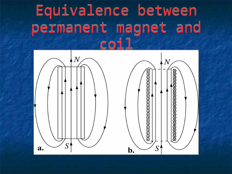
Equivalence between permanent magnet and coil
Equivalence between permanent magnet and coil

Magnetics - some theoryMagnetics - some theory
A magnet attracts or repels another magnet – this gives us the first observable interaction in the magnetic field –it also attracts a piece of iron.
It will not attract a piece of copper. Conclusion: there are different types of material
in terms of their magnetic properties. Magnetic properties are governed by the
permeability of the material, [henry/meter]

Magnetics - some theoryMagnetics - some theory
The strength of the magnetic field is usually given by the magnetic flux density B [tesla]
The magnetic flux density is also called magnetic induction
The magnetic field intensity H [ampere/meter]. The relation between the two is simple:
The strength of the magnetic field is usually given by the magnetic flux density B [tesla]
The magnetic flux density is also called magnetic induction
The magnetic field intensity H [ampere/meter]. The relation between the two is simple:
B = 0
rH

Magnetics - some theoryMagnetics - some theory
0=4πx10 [H/m] is the permeability of vacuum r is the relative permeability of the medium in
which the relation holds, r is given as the ratio between the permeability
of the medium and that of vacuum A dimensionless quantity associated with each
material in nature. Permeabilities of some useful materials are given
next.

Magnetics - some theoryMagnetics - some theory
Magnetic materials: Diamagnetic, r < 1 Paramagnetic r > 1 Ferromagnetic r >> 1 (iron-like) The latter are often the most useful materials when
working with magnetic fields. There are other types of magnetic materials
(ferrites, magnetic powders, magnetic fluids, magnetic glasses, etc.)
Magnetic materials: Diamagnetic, r < 1 Paramagnetic r > 1 Ferromagnetic r >> 1 (iron-like) The latter are often the most useful materials when
working with magnetic fields. There are other types of magnetic materials
(ferrites, magnetic powders, magnetic fluids, magnetic glasses, etc.)

Permeabilities of diamagentic and paramagnetic materials
Permeabilities of diamagentic and paramagnetic materials
Material Relative Permeability Material Relative PermeabilitySilver 0.999974 Air 1.00000036Water 0.9999991 Aluminum 1.000021Copper 0.999991 Palladium 1.0008Mercury 0.999968 Platinum 1.00029Lead 0.999983 Tungsten 1.000068Gold 0.999998 Magnesium 1.00000693Graphite (Carbon) 0.999956 Manganese 1.000125Hydrogen 0.999999998 Oxygen 1.0000019
Material Relative Permeability Material Relative PermeabilitySilver 0.999974 Air 1.00000036Water 0.9999991 Aluminum 1.000021Copper 0.999991 Palladium 1.0008Mercury 0.999968 Platinum 1.00029Lead 0.999983 Tungsten 1.000068Gold 0.999998 Magnesium 1.00000693Graphite (Carbon) 0.999956 Manganese 1.000125Hydrogen 0.999999998 Oxygen 1.0000019
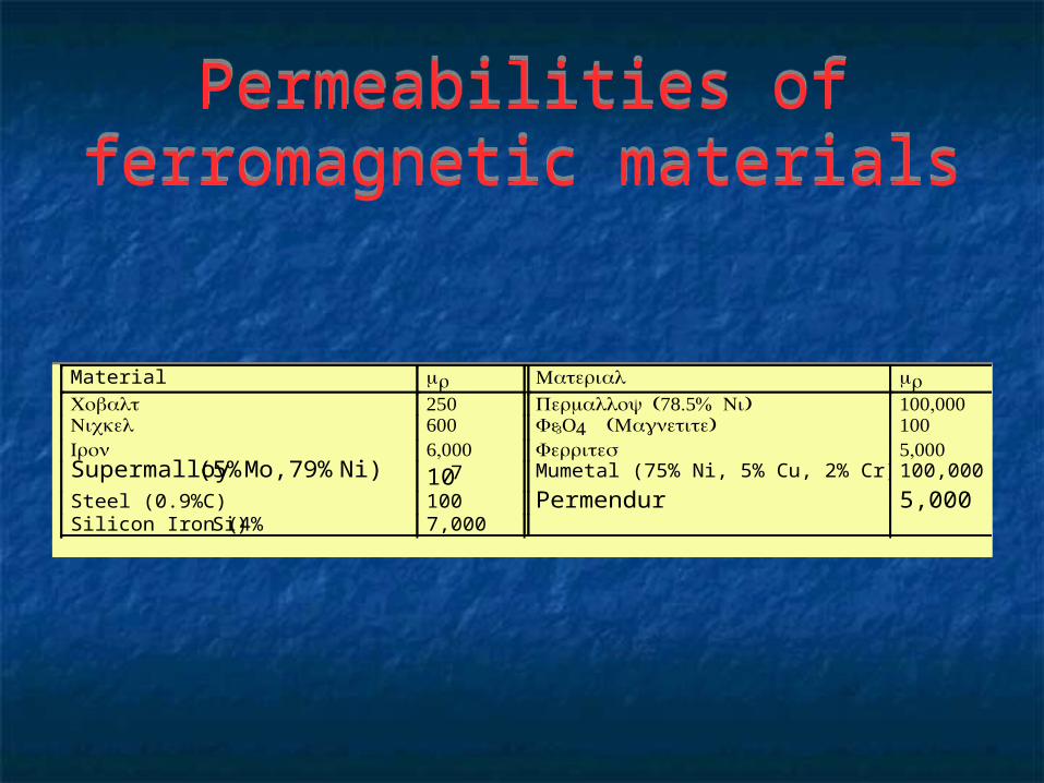
Permeabilities of ferromagnetic materials
Permeabilities of ferromagnetic materials
Material r Material rCobalt 50 (8.5% )Permalloy Ni 00,000Nickel 600 Fe3O4 ( )Magnetite 00Iron 6,000 Ferrites 5,000Supermalloy (5% Mo, 79% Ni) 107 Mumetal (75% Ni, 5% Cu, 2% Cr) 100,000
Steel (0.9%C) 100 Permendur 5,000Silicon Iron (4% Si) 7,000
Material r Material rCobalt 50 (8.5% )Permalloy Ni 00,000Nickel 600 Fe3O4 ( )Magnetite 00Iron 6,000 Ferrites 5,000Supermalloy (5% Mo, 79% Ni) 107 Mumetal (75% Ni, 5% Cu, 2% Cr) 100,000
Steel (0.9%C) 100 Permendur 5,000Silicon Iron (4% Si) 7,000

Magnetics - some definitionsMagnetics - some definitions
Soft magnetic materials are those for which magnetization is reversible
Hard magnetic materials are materials which retain magnetization and are therefore used for production of permanent magnets
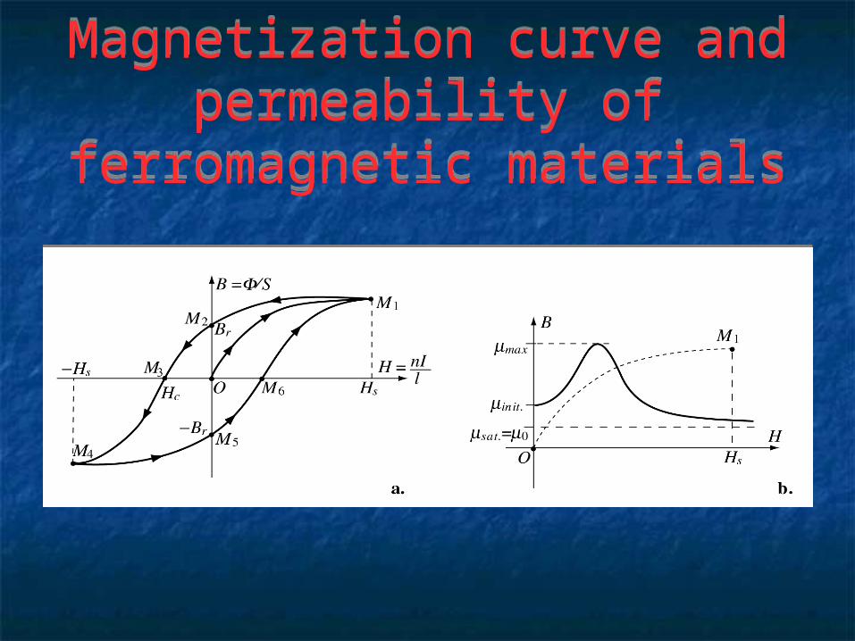
Hysteresis - a property of ferromagnetic materials best explained through the magnetization curve
Nonlinear magnetization: permeability is field dependent.
Soft magnetic materials are those for which magnetization is reversible
Hard magnetic materials are materials which retain magnetization and are therefore used for production of permanent magnets
Hysteresis - a property of ferromagnetic materials best explained through the magnetization curve
Nonlinear magnetization: permeability is field dependent.
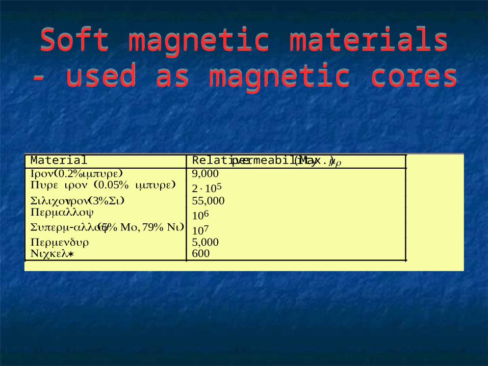
Soft magnetic materials - used as magnetic cores
Soft magnetic materials - used as magnetic cores
Material Relative permeability (Max.) r(0.% Iron )impure 9,000 (0.05% )Pure iron impure ×05
Silicon iron(3% )Si 55,000Permalloy 06
- Superm alloy(5% , Mo 9% )Ni 0Permendur 5,000
*Nickel 600
Material Relative permeability (Max.) r(0.% Iron )impure 9,000 (0.05% )Pure iron impure ×05
Silicon iron(3% )Si 55,000Permalloy 06
- Superm alloy(5% , Mo 9% )Ni 0Permendur 5,000
*Nickel 600

Hard magnetic materials - used in permanent magnets
Hard magnetic materials - used in permanent magnets
Material r ( - - )Alnico Aluminum Nickel Cobalt3-5 ( - )Ferrite Barium Iron .
- (Sm Co - )Sammarium Cobalt .05- - ( - - )Ne Fe B Neodymium Iron Boron.05
Material r ( - - )Alnico Aluminum Nickel Cobalt3-5 ( - )Ferrite Barium Iron .
- (Sm Co - )Sammarium Cobalt .05- - ( - - )Ne Fe B Neodymium Iron Boron.05
Magnetization curve and permeability of ferromagnetic
materials
Magnetization curve and permeability of ferromagnetic
materials

Currents, fields and fluxCurrents, fields and flux
Relation between current and magnetic flux density.
For a long straight wire carrying a current I and placed in a medium of permeability 0r. The magnitude of the magnetic flux density is: r is the distance from the wire to the location
where the field is calculated the magnetic field is a vector and has a
direction (next) - field is perpendicular to I
B = 0
r
I
π r

Relation between current and magnetic field
Relation between current and magnetic field

General idea:General idea:
In more practical configurations, the wire may not be very long or it may be wound in a coil but, nevertheless, the basic relations hold: The larger the current and/or the permeability, or the shorter the distance between current and the location where the magnetic field is needed, the larger the magnetic field
In more practical configurations, the wire may not be very long or it may be wound in a coil but, nevertheless, the basic relations hold: The larger the current and/or the permeability, or the shorter the distance between current and the location where the magnetic field is needed, the larger the magnetic field

Magnetic fluxMagnetic flux
Flux is the integral of flux density over an area S:
If B is constant over an area S and at an angle to the surface, flux is =BScos.
Unit of flux is the weber [Wb] 1 [Wb] = 1 [Tm2] Flux relates to power and
energy in the magnetic field
Flux is the integral of flux density over an area S:
If B is constant over an area S and at an angle to the surface, flux is =BScos.
Unit of flux is the weber [Wb] 1 [Wb] = 1 [Tm2] Flux relates to power and
energy in the magnetic field
= B . d s
S
Wb

Force in the magnetic fieldForce in the magnetic field
Force in a magnetic field is based on the fact that a charge moving at a velocity v in a magnetic field B experience a force (called the Lorentz force) given as: vB is the angle between the
direction of motion and the direction of B
F is perpendicular to both v and B as shown (next).
Force in a magnetic field is based on the fact that a charge moving at a velocity v in a magnetic field B experience a force (called the Lorentz force) given as: vB is the angle between the
direction of motion and the direction of B
F is perpendicular to both v and B as shown (next).
F = qvBsin vb
[ ]N

Relation between charge, current and force in a magnetic
field
Relation between charge, current and force in a magnetic
field

Forces on currentsForces on currents
Charges (electrons) move in conductors (current)
Two wires carrying currents in opposite directions exert forces on each other
The forces the wires exert on each other are in opposite direction and tend to separate the wires.
If the currents were in the same direction (or the magnetic field reversed) the wires would attract.

Forces on currentsForces on currents For long parallel wires, the force for a length L of
the wire is: F = BIL For other configuration the relation is much more
complicated but force is proportional to B, I and L. A single wire carrying a current will be attracted
or repelled by a permanent magnet These principles are the basis for magnetic
actuation Forces can be very large since B, I and L can be
controlled and can be quite large.
For long parallel wires, the force for a length L of the wire is: F = BIL
For other configuration the relation is much more complicated but force is proportional to B, I and L.
A single wire carrying a current will be attracted or repelled by a permanent magnet
These principles are the basis for magnetic actuation
Forces can be very large since B, I and L can be controlled and can be quite large.

Inductive sensorsInductive sensors
Rely on two basic phenomena: Inductance of a coil and changes of inductance
due to a variety of effects (distance, materials, dimensions, etc.)
Induced currents in conducting materials. Inductance is a property of a magnetic device just
as capacitance is the property of an electric device Usually associated with coils and conductors Inductance can be made to respond (change) to
almost any physical property either directly or indirectly

InductanceInductance
Defined as the ratio of flux and the current that produced is:
Inductance is independent of current since is current dependent
All magnetic devices have an inductance but inductance is most often associated with coils
Defined as the ratio of flux and the current that produced is:
Inductance is independent of current since is current dependent
All magnetic devices have an inductance but inductance is most often associated with coils
L =
I
webber
ampere
or [ henry ]

InductanceInductance
Two types of inductance: 1. Self inductance: the ratio of the flux produced by a
circuit (a conductor or a coil) in itself and the current that produces it. Usually denoted as Lii.
2. Mutual inductance: the ratio of the flux produced by circuit i in circuit j and the current in circuit i that produced it. Denoted as Mij.
A mutual inductance exists between any two circuits as long as there a magnetic field (flux) that couples the two.
This coupling can be large (tightly coupled circuits) or small (loosely coupled circuits).

Self and mutual inductanceSelf and mutual inductance

Inductors and transformersInductors and transformers
A coil is also called an inductor (having inductance)
Transformers are made of two or more coils, coupled through mutual inductances
Many sensors are in fact transformers of one type or another
Transformer are ac devices
A coil is also called an inductor (having inductance)
Transformers are made of two or more coils, coupled through mutual inductances
Many sensors are in fact transformers of one type or another
Transformer are ac devices

The transformerThe transformer
A primary and a secondary circuit A magnetic path for the flux (closed or open) Transformer ratio is N1/N2
A primary and a secondary circuit A magnetic path for the flux (closed or open) Transformer ratio is N1/N2

The transformerThe transformer
An ac voltage applied to one circuit (or coil) produces a voltage in any other circuit that couples to the driving coil as shown in Figure 5.17.
Coils, of N1 and N2 turns respectively. All flux produced by coil 1 couples to coil 2 through the magnetic circuit made of a ferromagnetic material (iron for example). The voltages and currents relate as follows (a = N1/N2)
V2 = N2N1
V1 = 1aV1, I2 = N1N2
I1 = aI1

The transformerThe transformer
The transformer so defined is a tightly coupled transformer (all flux links both coils)
Loosely coupled transformers: Only part of the flux produced by one coil links the
second coil The magnetic path is said to be open These are more often used in sensors than tightly
coupled transformers
The transformer so defined is a tightly coupled transformer (all flux links both coils)
Loosely coupled transformers: Only part of the flux produced by one coil links the
second coil The magnetic path is said to be open These are more often used in sensors than tightly
coupled transformers

Inductive sensors - generalInductive sensors - general
Most inductive sensors relay on self inductance, mutual inductance or transformer concepts
Inductors require currents to sense (passive devices) A magnetic field is produced - the sensor can be said to
respond to changes in this magnetic field. The most common type of stimuli sensed by inductive
sensors are position (proximity), displacement and material composition.
Inductance and induction is often used to sense other quantities indirectly.

Inductive proximity sensorsInductive proximity sensors
Inductive proximity sensor contain: At the very least a coil (inductor) Generates a magnetic field The coil’s inductance depends on dimensions of the coil, number of
turns and materials around it. The current and the diameter of the coil define the extent to which the
field projects away from the coil and therefore the span of the sensor.
• Operation: As the sensor gets closer to the sensed surface the inductance of the
coil increases if the sense surface is ferromagnetic It is then sufficient to use a means of measuring this inductance to infer
proximity and position

Sensing position and proximitySensing position and proximity

Inductance - additional detailsInductance - additional details
Inductance is measured with an ac current source and a voltmeter or an ac bridge.
By measuring the voltage across the inductor the impedance can be evaluated and since Z=R+jL (R is the ohmic resistance and =2πf the angular frequency) the inductance L is immediately available as a measure of position of the coil or proximity to the surface.
We assumed here that R is constant but even if it is not, the impedance in air (nothing being sensed) is known and this can be used for calibration.

Inductance sensor - practicalInductance sensor - practical
A ferromagnetic core is added to increase the inductance of the sensor.
Most often iron or a ferrite (a powdered magnetic material such as Fe2O3, CoO2 in a binding material and sintered into the shape needed)
A shield may be placed around the sensor to prevent sensitivity to objects on the side of the sensor or at its back
The net effect of the shield is to project the field in front of the sensor and hence increase both the field (inductance) and the span of the sensor.
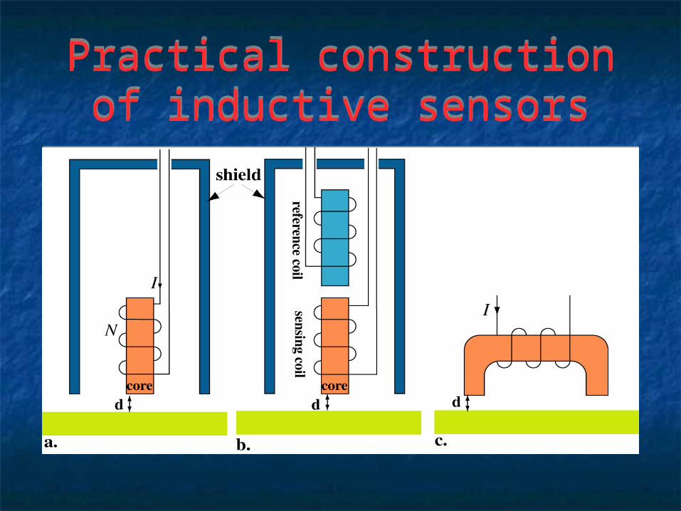
Practical construction of inductive sensors
Practical construction of inductive sensors

Proximity sensor with reference coil
Proximity sensor with reference coil
In other sensors, there are two coils, one serving as reference, the other as a sensor (Figure 5.19b).
The reference coil’s inductance remains constant and the two are balanced.
When a surface is sensed, the sensing coil has a larger inductance and the imbalance between the coils serves as a measure of distance.

Closed magnetic circuit proximity sensor
Closed magnetic circuit proximity sensor
Other sensors, like the one is Figure 5.19c may employ a closed magnetic circuit which tends to concentrate the magnetic field in the gaps and usually do not require shielding since within the sensor, the magnetic field is constrained within the ferromagnetic material
Other sensors, like the one is Figure 5.19c may employ a closed magnetic circuit which tends to concentrate the magnetic field in the gaps and usually do not require shielding since within the sensor, the magnetic field is constrained within the ferromagnetic material

Eddy current sensorsEddy current sensors
Inductive proximity sensors are sensitive to the presence (proximity) of non-conducting ferromagnetic materials or to any conducting media.
Nonconductors in general do not affect proximity sensors.
Many inductive proximity sensors are of the eddy current type.
Inductive proximity sensors are sensitive to the presence (proximity) of non-conducting ferromagnetic materials or to any conducting media.
Nonconductors in general do not affect proximity sensors.
Many inductive proximity sensors are of the eddy current type.

Eddy current sensorEddy current sensor

Eddy current sensorsEddy current sensors
The name eddy current comes from the fundamental property of ac magnetic fields to induce currents in conducting media
There are two related phenomena at work. The currents produced in the conductor, called eddy
currents because they flow in closed loops, cause a field which opposes the original field that produces them (Lenz’s law). This field reduces the net flux through the sensor coil.
Second, the currents flowing in the conductor being sensed, dissipate power.

Eddy current sensorsEddy current sensors
The sensing coil is now forced to supply more power than it would otherwise supply and hence, given a constant current, its effective resistance increases.
This change in impedance from Z=R+jL to Z’=R’+jL’ is easily sensed either in absolute terms or as a change in the phase of the measured voltage (given a constant current).
A second effect is the skin effect in conducting media.

Eddy current sensorsEddy current sensors
A magnetic field penetrating into a conducting medium is attenuated exponentially from the surface inwards (and so are the eddy currents and other quantities):
A magnetic field penetrating into a conducting medium is attenuated exponentially from the surface inwards (and so are the eddy currents and other quantities):
B = B0
e− d / δ
, or : I = I0e
− d / δ
B0 and I0 are the flux density and the current density at the surface, d is depth in the medium δ is the skin depth. Skin depth is defined as the depth at which the field (or current) is attenuated to 1/e of its value at the surface.

Skin depthSkin depth
For planar surfaces, skin depth is given as: For planar surfaces, skin depth is given as:
δ =
1
π f μσ
m
f is the frequency of the field. Penetration depends on frequency, conductivity and permeability. The main implication here is that the sensed conductor must be thick enough compared to skin depth. Alternatively, operation at higher frequencies may be needed.

Proximity sensors - comments Proximity sensors - comments
Proximity sensors (either capacitive or inductive) can be used to sense distance.
Their transfer function is much too nonlinear and their span too small to be effective except for short spans
Proximity sensors are usually used as switches to provide a clear indication when a certain, preset distance is reached.
Inductive sensors can produce an electric output such as voltage based on the change in their impedance
Often the inductor is part of an oscillator (LC oscillator is the most common) and the frequency of the sensor is then used as the output.

Inductive sensorsInductive sensors

Eddy current sensors for NDTEddy current sensors for NDT

Eddy current sensors for NDTEddy current sensors for NDT

Position and displacement sensing
Position and displacement sensing
Position and displacement are usually understood as measuring the exact distance from a point or the travel of a point relative to another.
Requires accurate measurements and possibly linear transfer functions of the sensors involved.
One approach to this task is through the use of variable inductance sensors, sometimes called variable reluctance sensors.

Magnetic reluctanceMagnetic reluctance
Magnetic reluctance is the equivalent magnetic term to resistance and is defined as
Magnetic reluctance is the equivalent magnetic term to resistance and is defined as
R =
L
S
H
Reluctance is smaller the shorter the magnetic path, the larger its cross sectional area and the larger its permeability. Reluctance is then related to inductance through permeability and reducing reluctance also increases inductance and vice versa. Typically, the reluctance of a coil can be changed by adding a gap in the magnetic path and changing the effective length of this gap.

Movable core sensorsMovable core sensors Thus, a simple method of changing inductance of a
coil is to provide it with a movable core: The further the movable core moves in, the smaller
the reluctance of the magnetic path and the larger the change in inductance.
This type of sensor is called a linear variable inductance sensor. (Linear here means that the motion is linear).
Inductance is a measure of the position of the core The same of course may be used to measure force,
pressure, or anything else that can produce linear displacement.
Thus, a simple method of changing inductance of a coil is to provide it with a movable core:
The further the movable core moves in, the smaller the reluctance of the magnetic path and the larger the change in inductance.
This type of sensor is called a linear variable inductance sensor. (Linear here means that the motion is linear).
Inductance is a measure of the position of the core The same of course may be used to measure force,
pressure, or anything else that can produce linear displacement.

Variable reluctance (inductance) sensor - the LVDT
Variable reluctance (inductance) sensor - the LVDT

LVDTLVDT
A better displacement sensor is a sensor based on the idea of the transformer.
Based on one of two related principles; the distance between two coils of a transformer is
varied (the coupling between the coils changes) or the coupling coefficient between the two coils is
varied by physically moving the core while the two coils are fixed.
Both principles are shown next.
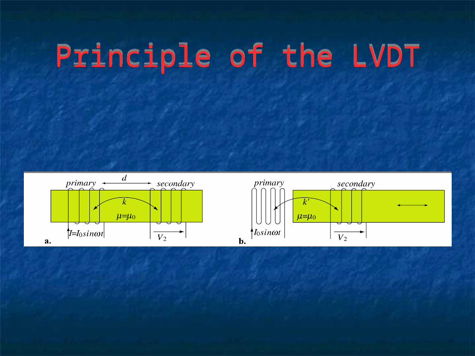
Principle of the LVDTPrinciple of the LVDT

LVDTLVDT
LVDT - Linear Variable Differential Transformer
Based on the 2nd principle One primary coil, two secondary coils
connected in opposition Output is zero if coupling is balanced Motion to either side changes the output
LVDT - Linear Variable Differential Transformer
Based on the 2nd principle One primary coil, two secondary coils
connected in opposition Output is zero if coupling is balanced Motion to either side changes the output

Structure and equivalent circuit of an LVDT
Structure and equivalent circuit of an LVDT
The output is zero for core centered Motion to the right or left changes the output in different
directions (polarity) This is a variable reluctance transformer Detects both distance and direction of change
The output is zero for core centered Motion to the right or left changes the output in different
directions (polarity) This is a variable reluctance transformer Detects both distance and direction of change

LVDT - propertiesLVDT - properties
LVDTs are very sensitive and useful In a relatively small range of motion, the output
is linear. The primary coil is driven with a stable
sinusoidal source at a constant frequency and the core is ferromagnetic.
The whole sensor is enclosed and shielded so that no field extends outside it and hence cannot be influenced by outside fields.

LVDT - propertiesLVDT - properties
The core slides in and out and that motion is often used for accurate measurements of displacement for applications in industrial control and machine tools.
LVDT sensors are extremely rugged and come in various dimensions to suit many needs (some as small as 10mm long).
In most practical applications, the voltage output is measured (amplification is usually not needed) while the phase is detected with a zero-crossing phase detector (a comparator).

LVDT - propertiesLVDT - properties
Frequency of the source must be high with respect to the frequency of motion of the core (a figure of 10 times higher is common) to avoid errors in the output voltage due to slow response of the LVDT.
The operation of LVDTs can be from ac sources or dc sources (with internal oscillator providing the sinusoidal voltage).
Typical voltages are up to about 25V while output is usually below 5V.
Resolution can be very high while the linear span is about 10-20% of the length of the coil assembly
RVDT - Rotary Variable Differential TransformerRVDT - Rotary Variable Differential Transformer
A variation of the LVDT Intended for angular displacement and rotary
position sensing. In all respects it is identical in operation to the
LVDT device but the rotary motion imposes certain restrictions on its construction.
The span is given in angles and can be up to ±30 to ±40. Beyond that the output is nonlinear.

RVDTRVDT

Response of an RVDTResponse of an RVDT