electric calabasas calif rantec oe-25*/len … · 1-5 modulation generator ... range distance to...
TRANSCRIPT

A-AiII 6" EMERSON ELECTRIC CC CALABASAS CALIF RANTEC DIV F/S 9/5NOIFICATION OF OE-25*/LEN TACTICAL AIR NAVIGATION (TACAN) ANTE--ETC(U)JUL Al J D BAIN DTF01-60-C-10iAS
UNCLASSIFIED FAA/RO-8I/53 MI.
mhhmhhmhmmhusmmhhhhhhEEmh
END

*~,& 111 '*L 536i1111 .1 E 30
411111_2 ____ __ L 6
MICROCOPY RESOLUTION TEST CHART
NATIONAL BUREAU OF STANDARDS 19HA A

. LJOT/FAA/RD-81,53 Modification of OE-258/URNSystems Research & Tactical Air NavigationDevelopmen ServiceWashington, D.C. 20590 (TACAN) Antenna Group
James D. BainRANTEC DIVISIONEMERSON ELECTRIC CO.24003 Ventura BoulevardCalabasas, CA 9139
July 1981
Final Report
This document is available to the U.S. publicthrough the National Technical InformationService, Springfield, Virginia 22161.
IIE82 Uo oAtdA, ,.,o f09, , ", , .i}"A, t.

NOTICE IThis document is disseminated under the sponsorship of
the Department of Transportation in the interest ofinformation exchange. The United States Government
assumes no liability for its contents or use thereof.
The United States Government does not endorse products
or manufacturers. Trade or manufacturer's names appearherein solely because they are considered essential to
the object of this report.

Technical Report Documentation Page
1. Report No. 2. Government Accession No. 3. Recipient's Catalog No.
DOT/FAA/RD-81/53
4. Title and Subtitlet 5. Report Dot.e uy 18
Modi ficati on of OE-258/URN Tactical Air Navigation 6. Performing Organization Code
(TACAN) Antenna Group8. Performing Organi zation Report No.
7. Aurhorls
James D. Bain9. Performing Organization Name and Address 10. Work Unit No. (TRAIS)
Rantec Division, Emerson Electric Corp. 11. Contract or Grant No.24003 Ventura Boulevard DF18--04
CalabsasCA 93023 Type of Report and Period Covered
12. Sponsoring Agency Name and Address Final ReportU.S. Department of Transportation October 1980 to July 1981Federal Aviation Administration _______________
Systems Research and Development Service 1.Sponsoring Agency Code
Washin ton D.C. 20590______________15. Supplementary Notes
16. Abstract
'he 0E-258/URN TACAN Antenna Group has been modified to provide a remote monitorcapability. This remote monitor meets the requirements of the IEEE-488 interfacespecification. A test set (controller) has been provided for use with the antennagroup.
17. Key Words 18. Distribution Stetement
TACAN, Remote MoioAtnaThis document is available to the U.S. publicthrough the National Technical InformationService, Springfield, Virginia 22161.
19. Security Clessif. (of this repelt 20. Security Clessif. (of this Page) 21. No. of Pages 22. Price
Unclassified Unclassified 6o
Ferm DOT F 1700.7 (8-72) Reproduction of completed page authorized
Me I lip-
.. . . . ..- , -
-A 1= '.5t = I • U
. i, ii '11
-0
-~ TD
i,44,
0 0 0. 0-f
= ,.@ 0 0_ ,,,,* .3 _ -
o
• iii : .- ,ii ,ii ,, t
r --
=ceg 9i i f I li Il 11i 1 11 11011- 0
M i |'
" I I I I I I I I'
- Iq
* III II~l lll ll II IIlIHIIIIH II III~l IIl lllIilI lllllllllInllllilllill~~~~~~ a" ' 'T"I ''rTT'r ~ ''r TTT ''Tjr ,,~,r 'r ~
3
i i i ,. , +I
1 IiI ""u g5i
ii.

PREFACE
This final report describes the work done to modify the solid state
OE-258/URN TACAN antenna group to remote monitoring of the Built-in-Test
Equipment (BITE) including the following:
0 Modification description
0 Operation
0 Installation of system
* Test results
* Conclusions and reconmmendations
I AcCession For
ITIC TAB
I~~.1V t j
opJINSPECJ --
Iviand/orspecial

TABLE OF CONTENTS
Section/ Paragraph Page
1.0 INTRODUCTION .. .. .... ...... ...... ....... 1
1.1 Program Description .. .. ..... .... .... .. 11.2 Antenna Group Description .. .. ..... .... .... 1
2.0 ANTENNA GROUP MODIFICATIONS. .. ..... ...... ..... 9
2.1 General .. ... .... .... .... ..... .... 92.2 BITE Systeri Concept .. .. ..... .... .... .. 11
2.2.1 Modulation Frequency. .. .. .... .... .. 112.2.2 Trigger Signals. .. ... ..... .... .. 112.2.3 Antenna Monitor. .. ... ..... .... .. 12
2.3 BITE System Operation .. .. .... ..... ...... 132.3.1 Trigger Faults. .. .. .... .... ..... 132.3.2 Clock Faults. .. .. .... .... ....... 132.3.3 Power Supply. .. .. .... .... .... .. 152.3.4 Monitor Diode .. .. ..... .... ...... 152.3.5 Generator Null. .. .. .... ..... .... 152.3.6 Antenna Parameters .. .. ... .... ..... 152.3.7 System Radiated Power .. .. .... ....... 162.3.8 BITE Clock .. .. ... .... .... ..... 16
2.4 Computer Interface .. .. ... .... .... ..... 162.4.1 General .. .... ..... ...... .... 162.4.2 Data Lines 162.4.3 Data Transfer................17
3.0 TEST SET .. .. .... ...... ...... ..... ... 18
43.1 General. .. .... .... .... .... ....... 183.2 Executive Mode. .. .. .... .... .... ..... 183.3 Status Test Mode .. .. ... .... .... ....... 213.4 Bite Test Mode. .. .. .... .... ..... .... 213.5 DME-Only Mode . .. .. .. .. .. .. .. .. .. . .21
3.6 Data-Print Mode .. .. .... ..... .... .... 22j3.7 Error Decoding. .. .. .... .... ..... .... 22
3.7.1 General 223.7.2 STATUS TEST Operation ...... 263.7.3 EXECUTIVE Interrupt Operation .. .. ....... 26
3.8 Software .. .. .. .... .... .. .. .. .. ... 27

TABLE OF CONTENTS (Cont'd)
Section/Paragraph Page
4.0 ANTENNA GROUP TESTS AND INSTALLATION .......................... 42
4.1 Acceptance Tests ........................................ 42
4.2 Installation ............................................ 42
5.0 CONCLUSIONS ................................................... 43
6.0 RECOMMENDATIONS ............................................... 44
7.0 REFERENCE DOCUMENTS ........................................... 45
APPENDIX A ANTENNA FAULT TESTS Al thru A14
LIST OF ILLUSTRATIONS
Figure Page
1-1 AT-100 TACAN Antenna Group, Relationship of Units ............ 2
1-2 Antenna Vertical Radiating Element ........................... 4
1-3 TACAN Antenna ................................................ 5
1-4 TACAN Antenna - RF Feed Structure ............................ 6
1-5 Modulation Generator ...................................... 8
2-1 Modulation Generator - Internal Configuration ................ 10
2-2 Simplified Block Diagram BITE and Interface System ........... 14
3-1 Display for Executive Mode .................................. 19
3-2 Test Set - Data Matrix Display ............................... 20
3-3 Data Printout Examples ....................................... 23
3-4 Main Program (FIND 1) ........................................ 28 thru 32
3-5 Print Program (FIND 2) ....................................... 33 thru 36
3-6 Demonstration Program (FIND 4) ............................... 37 thru 41
1LIST OF TABLES
Table Page
3-1 DATA LATCH MENU .......................... ................... 24/25
vi

1.0 INTRODUCTION
1.1 Program Description
This program, conducted in accordance with the requirements of
Department of Transportation (DOT) Contract Number DTF01-80-C-10148, was
designed to provide a modified Rantec Tactical Air Navigation (TACAN) Antenna
Group (Model OE-258/URN) and provide field support during testing at Federal
Aviation Authority (FAA) Technical Center at Atlantic City, New Jersey. The
antenna modifications were in accordance with the contract Statement of Work.
These modifications provide a computer interface between the TACAN Antenna
Group and the Second Generation Very High Frequency Omnidirectional Radio
Range/Tactical Air Navigation (VORTAC) System. The interface is in accordance
with the Institute of Electrical and Electronics Engineers (IEEE) - 488 stand-
ards. In addition, a test set duplicating the control and display functions
of the VORTAC System was provided.
The antenna group furnished for this contract was transferred to the
FAA from the United States (U.S.) Navy. No changes were made to the antenna.
The modulation generator, however, was extensively modified and has been furn-
ished as an engineering prototype for test and evaluation.
1.2 Antenna Group Description
The OE-258/URN TACAN Antenna Group is an all-band, solid-state,
electronically modulated antenna for use with Tactical Air Navigation (TACAN)
systems. It is used with the TACAN ground transponder for both transmission
and reception, and provides the horizontally rotating 9-lobed pattern for the
TACAN azimuth modulation characteristic. The use of electronic modulation
deletes the requirement for any moving parts within the antenna, thus improving
reliability and reducing power consumption. The Antenna Group consists of two
major units, the Antenna and the Modulation Generator. This antenna is used in
conjunction with a TACAN radio set (ground transponder) to provide a navigational
signal for aircraft (distance and bearing for military users and distance for
all users of the National Airspace). Figure 1-1 depicts this equipment relation-
ship. Aircraft equipped with a cc:npanion TACAN interrogator unit derive slant-
range distance to the ground beacon and bearing angle, referenced to majnetic
north.

AT-1007ACAN ANTENNA
MCDI.AICNDRIVE (Ii)
TRANSPONDER(NOT PART OF
STRIGGER
---- I '00
A1I I3 w~ O'ER -
Figure 1 -1. AT- 100 TACAN Antenna Group,Relationship of Units
2

a. Antenna. The antenna unit is a cylindrical array approximately
84 inches high and 60 inches in diameter. It consists of 36 identical andequally spaced vertical radiating columns, providing for the transmission and
reception of the pulse-paired rf signals. One antenna element is shown in
Figure 1-2. The use of the cylindrical array configuration for the TACAN antenna
presents several advantages:
(1) The use of cavity feed slots within the vertical arrays prcvidesa very pure vertically polarized signal from the antenna, thus
eliminating cross-polarization problems.
(2) Since the carrier, 15 Hz and 135 Hz modulation components are
all radiated from the slots, they have the same basic radiation
characteristics. Low-level signals below the horizon are main-
tained for all radiation components, thus minimizing ground
reflection problems.
(3) Careful matching of the radiators and other rf components,
together with the basic array geometry, permits single antenna
operations over the entire TACAN band.
The cylindrical antenna base houses the modulators, power splitters,
and associated circuitry and increases the overall height to 124 inches, with
a total weight of approximately 850 pounds. Figure 1-3 shows the complete
antenna with its environmentally protecting radome. Figure 1-4 diagrams theinternal arrangement of the rf feed structure. In this figure:
Al thru A36 are the vertical radiators.
A37 thru A39 are the azimuth feeds (12-way power dividers
and PIN diode modulations).A40 is the input, 3-way power divider.
A4OAI is the antenna-monitor printed circuit card.
J3/W40 provides the antenna rf input path.
J2/W42 provides the modulation drive input from the
modulation generator.J3/W41 provides the antenna monitor connections to the
modulation generator from IA4OA1.
-A.

urnM M, -& =OVA mMW aMSeO am ZMI m mM. amma is Am , mm mm Immmx f.me.mmmi. y un
m Mmm am -
LOOPi.-J FSew
INPUT V5R 1.50 MX NO I O.A CAVITY9
LEED MECAL. 5-PPCIF (MONrRcS%5TN:
FeEw DI9-rR1UT~ON (BANO Ca~E-67-)rwU-eteNT No. \/LTHC- pA-e (oq,*)1
(a .141 -11
7 .5095 - A5
II .57Q2 .4512 -119
-B2 -Co-

REVISIONSI= ~ DSRIPTION T APE
FF. N'PJT
CAVITY Cre IS. PQ)
M 12. -&Nr E <OUALLy -P~-r~
NONO. o NO. it NO. %Z
(Tryp t-z PL)
IM PART ON NOMENCLAIflRE ~mONo. MTWVV No. OR DUseP1noN am OD Ea INT
________ a"SQ I LIST Of MATERIALS
MAD ONEROUSIN C ONTRACT NO.
_______ mimeu ODAN DATE c.a~c.~..
E D"'S ±S W
____ ____ 'm ANTENNA \/6TMCAL_________ - ADITINCN GLE-MCNT
WIDE 10__0____ - D 004971
on - SSann0Y

Figure 1-3. TACAN Antenna
5

VWICA RD 14 A?
A16 AA
AIS CU-AA22r
A14 A/

KIcoIAL FD Na* A? Ad Al A All A12 AD) Aid A15 A16 All All A19 AM0 A21 A22 A23 A24 A25 AN AZI A AN Afl *1IM)
wi 4__ -1 ("~N I cu. I oI
______MM__ bb (b 66M~
4.MPS
WINWI
310 I ONA-11
A

NT A& AZ ADl AB AN A23 Ai 2 AN AN0 A31 A32 A R) ANj M Aft A Al A AS Al AS U
~66c~ 0T
AV) 43 A
LA
~ ~ '~>O _
'-'
SECIM~A-1
Fgure 1-4. TACMI Anitena F Fee Structure
6

W43 provides signals from the 36 monitor diodes on each
vertical divider (Al through A36) to 1A40A1.
Other rf cables are self explanatory.
b. Modulation Generator. The modulation generator provides the
36 drive signals for PIN diode modulators in the antenna, which in turn pro-
duce the TACAN system's horizontally rotating pattern in space.
This unit also provides bipolar signals to the beacon transponder
for timing the transmission of north and auxiliary reference bursts. A
bipolar 1350 Hz signal is also supplied for the generation of a Morse-code
station identification signal. Built-in-test equipment (BITE) circuits are
provided to continuously monitor antenna group performance. The modulation
generator is configured for mounting in a standard 19 inch wide rack, and
has a front panel height of 8.75 inches, as shown in Figure 1-5. The unit
is supplied in a self-contained cabinet with drawer slides.
I I
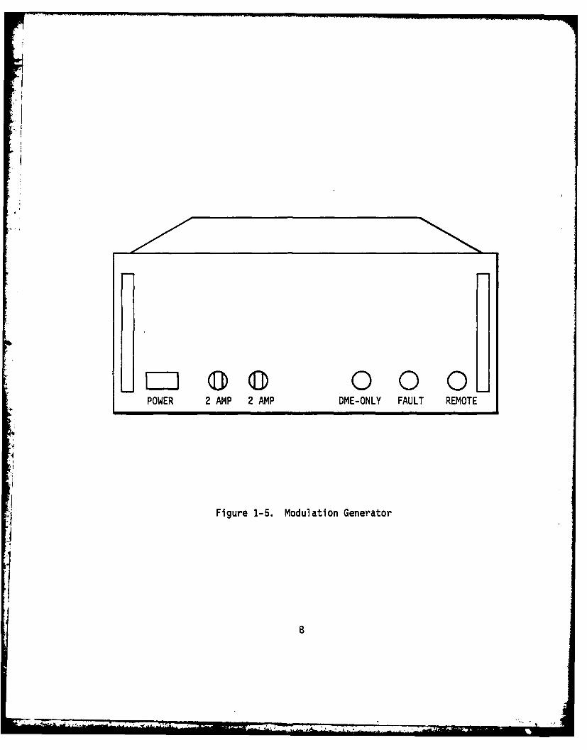
L 0 0 0POWER 2 AMP 2 AMP DME-ONLY FAULT REMOTE
Figure 1-5. Modulation Generator
ItA41;!

2.0 ANTENNA GROUP MODIFICATIONS
2.1 General
Modification of the TACAN Antenna Group was concerned only with the
built-in test equipment (BITE) functions of the modulation generator and its
interconnections to the computer interface. Thus no change was required in
the antenna assembly or to the basic modulation drive and trigger signals from
the modulation generator.
Physically the modulation generator front panel was modified such
that it contains only a power switch, fuses, and FAULT, DME ONLY, and AUTO OPR
lamp indicators. The rear panel was modified to contain the required interface
connector. The interior was rearranged so that the internal panel contains
certain of the operating and test switches formerly mounted on the front panel
as shown in Figure 2-1.
The function of the various controls is listed below:
o Test sample select switch - Selects various critical
wave forms for output on the test sample connector.
e Test sample connector - Outputs critical wave forms
for display on oscilloscope.
e Operation switch - In 'Normal' the BITE system is scanning
all 36 channels of modulation drive and antenna monitor
signals. In 'TEST' the BITE system count is stopped and
may be advanced one channel at a time using the -
* Advance switch
* Sync connector outputs a TTL pulse synchronous with the
start of each BITE channel count.
@ Aux trigger outputs a TTL pulse synchronous with the center
of the bipolar auxiliary reference signal.
A Nor trigger - outputs a TTL pulse synchronous with the center
of the bipolar north reference signal.
* Elapsed time - displays modulation generator operating time
in hours.
e North align thumbwheel - permits alignment of the antenna
to magnetic north.
9
Nowl.'-

W IN S NO N T W A C& ONN C T RS
--- W7 F~
'MS5T SAMPLEk ,LECT
NtTW- ALIGN ___ ___UmTM 4rIHa.MWtmeea 9 an 0
3 ma o-
AMON

REVISIONS
7- F7 1 71 IEAR RO4GL A55Y
HOLD OWIf BAR
CARD CAGC- ASV
M-AJX TRIGIER (WC)
NORTW TR*G(.-R (BINC)
RESE7T
)1F
-77aLAPED TIIA IM S0e O~R
OR -AERA _____CAIO
2 f NUE ON8 LIS~q T OMA ERALA S c~o4 1
'Iv A NLH

Circuit design for the required modifications required the replace-
ment of six printed circuit cards (PCC's) and the addition of one PCC.
The replaced PC cards eliminate the circuitry required for (BITE)
indicator lamps and beacon-shut-down circuitry which were a part of the
original modulation generator. Added circuitry allows these BITE signals to
be applied to the IEEE-488 bus. In addition the BITE circuitry for the
trigger and antenna monitor signals were improved. The bipolar trigger signals
are now monitored for both their positive and negative going voltage levels.
The antenna monitor was changed to permit detection of both over and under
modulation conditions and a column-radiated home level monitor was added.
Finally, a monitor-diode bias monitor was added.
The additional PC card was required for implementation of the
IEEE-488 interface circuitry. The total BITE/interface system is discussed
in paragraph 2.2 and shown in Figure 2-2.
In accordance with the contract this modified modulation generator
was furnished as an engineering prototype.
2.2 BITE System Concept
The BITE concept for the solid state antennas req-ires a different
criteria than that required for a mechanically rotating antenna. The required
parameters are discussed below together with their relationship to the solid
state design.
2.2.1 Modulation Frequency
The modulation frequency is determined by crystal oscillators run-
ning at 3.456 MHz. Two identical oscillators are used and their frequency is
compared to +0.35%. Thus the modulation and trigger frequency is accurately
controlled. There can be no "WOW" or other perturbation to this basic
frequency.
2.2.2 Trigger Signals
Since the trigger signals are generated electronically their basic
frequency is assured. However, the BITE system is required to assure that
4the bipolar signals are present and that they occur in correct relationshipand number.
11

2.2.3 Antenna Monitor
Since the solid-state antenna is an array, its' far-field pattern
is a summation of the carrier and modulation from several of its 36 vertical
columns. The accuracy of the bearing information is related within each
column to:
* Phase of modulation signal
@ Amplitude of modulation
0 Phase of rf signal
* Amplitude of rf signal
The phase and amplitude of the modulation signal is controlled to
a major extent by the 36 drive signals from the modulation generator. The
BITE system uses a secondarily generated drive signal as a comparison in a
summing network. The resultant 'generator-null' signal will detect errors of
greater than 2 degrees or 0.6 dB in phase and amplitude. Only one column drive
being outside these limits will have only a minor impact on antenna performance
(see Appendix A).
The phase of the rf signal is determined by the rf path length
through the antenna circuitry. This parameter is carefully controlled during
antenna manufacture and is unlikely to change to any marked extent.
The rf paths themselves are either low-loss coaxial cable or strip-
line. The only active components are the PIN diode modulators, the monitor
diodes and the circuitry on the antenna monitor PCC (A4OA1). Failure is, of
course, more likely to occur in these active components. Present in-service
antennas, however, indicate that these units are extremely reliable.
A monitor diode is connected to each of the 36 vertical arrays in
the antenna. As processed in the modulation generator, these monitor signals
will indicate both degradation of the rf signal level and degradation in the
modulation signal. Here again the loss of one column does not seriously
impact antenna performance.
12

The monitor diodes themselves are also checked (for bias level) to
insure that failure of this element does not cause system false alarms.
2.3 BITE System Operation
The characteristics of the modified BITE system is described in the
following paragraphs. Any detected fault will cause a system interrupt so
that appropriate system analysis and a BEACON SHUT DOWN or OME ONLY decision
can be made. A simplified block diagram of the BITE and interface circuit is
shown in Figure 2-2. Complete data concerning the operation of this cir-
cuitry is contained in the Technical Manual Addendum (Rantec No. 11016-ATM)
furnished with the modified antenna group.
2.3.1 Trigger Faults
The bipolar north, auxiliary, and tone signals are measured for the
amplitude and presence of both the positive and negative going portion of
their respective waveforms. These signals are also checked for the correct
number of pulses as a function of time:
North - One and only one pulse betweenconsecutive Auxiliary groups.
Auxiliary - Eight and only eight pulses betweenconsecutive North pulses.
Tone - Ten and only ten pulses between thenorth pulse and the second auxiliarypulse.
Failure of the North or Auxiliary pulses is decoded in the test set
as a hard error. Failure of the Tone signal is decoded as a soft failure.
2.3.2 Clock Faults
The presence of the system and reference clock signals is detected
and are decoded as soft failures. These two signals are compared to test the
clock frequency. Failure of this parameter is decoded as a hard failure.
Note: The failure of either clock disables the clock frequency
test. Prompt repair action is therefore dictated.
13
V -,.

U"A -I -I
U W0W1
7ppsoriffa +q
TCAIS-0" Of fr
Do "I I D i ,tf
7) eh)_
,AlotD~tA'
OEWI DATAJ.L AT,.Ci.
we2 AU
Ajoe~~ ForwoofAt TowMM1
All I i I TeAJ4
A- IWUCCOO AIA'-
Aws MtCIO - It 9#0-A&A(
AfOlf 2P*eMAZV -- _
Stiffe looI I
Eg-o ('al;.'074,r au~ raw &t
SIRI ofe
- --
.1

REVISION$!-I DEScWsPTIMe DTE ftW
P4C 6AI A2t ____2~ A.
toot
? f f V04* * W
----------------- Il
Y.A N lI-'
,)I lt4 DA fl
PItAIrtAA o FA Z7.
* e~~~~CLAt---- __
-n79 -- - - -
-. ~f Z~i .
>---* ------ of'
of of
q" ~ ~ 1112 1J 7 LISTOF ATEIAL

2.3.3 Power Supply
The + and - 16 volt power supply output is monitored for a five
percent deviation from nominal. A greater deviation is detected and decoded
as a soft error.
2.3.4 Monitor Diode
The 36 monitor diodes for detecting the radiated signal charac-
teristics of the 36 antenna columns are biased to achieve the required
linearity and sensitivity. If a diode becomes open or shorted this bias
voltage will change. This bias voltage level is detected by a comparator
which will detect a fault for voltages outside preset limits. This fault is
decoded as a soft failure.
In the test set, this parameter is detected on a column-by-column
basis during a complete status scan. A diode fault in any column disables the
antenna column radiated power and column percent modulation tesfs for that
column. This will prevent false hard failures of the >1 column error
parameters.
2.3.5 Generator Null
The drive signals to the 36 antenna column PIN-diode modulators are
tested for phase and amplitude using a separately generated waveform. This
test checks amplitude to within ±0.6 dB and phase to within ±2 degrees. A
detected fault is decoded initially as a soft error. Should more than one
column indicate a fault then a >1-column generator-null hard error is de-
tected and decoded.
2.3.6 Antenna Parameters
The output of the 36 monitor diodes are utilized to detect column
radiated power and column percent modulation faults. The column radiated
power is initially detected and decoded as a soft failure for signal levels
3 dB below the preset level. Percent modulation is initially detected and
15
A. .- '-z.--4 , , .... ' , .... : ... i " ' . • - , '• • 4 . J -. mmz "

decoded as a soft failure for levels less than 20 percent and greater than
60 percent for the composite 15 and 135 Hz modulation components. More-than-
one-column faults are detected and decoded as appropriate >1 column hard
errors.
2.3.7 System Radiated Power
The average carrier level for all 36 antenna columns is detected and
decoded as a soft failure for levels 6 dB below the preset level. This fault
disables the column radiated power and column percent modulation tests to pre-
vent hard failures when the beacon is off.
2.3.8 BITE Clock
A 3.75 Hz clock is used to drive the 36 channel sequential fault
detection system. The presence of the test channel address '1' bit is de-
tected and its absence is decoded as a hard failure.
2.4 Computer Interface
2.4.1 General
The computer interface uses the IEEE-488 bus. Since only one inter-
rupt (SRQ) line is present, then all antenna faults must result in interrupts
and the BEACON SHUTDOWN analysis must be handled by the system computer and/or
operator. The data transfer and interrupt operation are described in the
following paragraphs.
2.4.2 Data Lines
The interface provides a parallel 8-bit data bus. The modulation
generator therefore requires four 8-bit latches to handle the required data.
At each test channel address these latches are clocked and will contain all
of the antenna status information for that test address.
I1
~16
• " .. . ' . . - I ' ' " " . .. . ... . " . . .

2.4.3 Data Transfer
The modulation generator is designed as a "TALKER" using two
different secondary addresses. When placed in the TALK mode the contents of
each of the four data latches is read in turn, their enable circuits being
controlled and counted by the data transfer "hand-shake" process.
*1
17
_MA4

3.0 TEST SET
3.1 General
The test set provided with the TACAN antenna group is a Tektronix
4051 Graphics Computer which utilizes the IEEE-488 bus for inter-
facing with external periferal equipment. This unit has been programmed to
provide operational and system test data similar to that which would be im-
plemented in the Second Generation VORTAC System. The operation of the
various monitor and test modes of this unit are described in the following
paragraphs.
3.2 Executive Mode
Following initial system turn-on, the computer is placed in the exe-
cutive mode by depressing USER DEFINABLE KEY '1'. In this mode the computer
is in a loop which awaits a system interrupt. Such an interrupt is generated
whenever a system fault is detected. When in this mode, the modulation
generator AUTO lamp will be on and the computer display will be as shown in
Figure 3-1. When a fault is detected the display changes to that shown in
Figure 3-2 and appropriate errors will be indicated. For a column associated
error the display will include an 't' under the test channel address (TCA) of
the first column error and the COLUMN ERROR entry will be preceded by an 'X'.
When the fault is not column related, the 't' will appear under non-column (NC)
and the appropriate error will be indicated by a preceding 'X'. No individual
column-related errors are displayed for this mode - a STATUS TEST must be per-
formed to display these data.
L Following this fault indication, the computer program stops and the
operator is given the choice of various options to continue. It should be
noted that the TACAN Antenna Group interrupt is disabled at this time and is
reset only when the EXECUTIVE routine is restarted by depressing USER DE-
FINABLE KEY '1'. This is accomplished automatically following a data print-
out (see paragraph 3.6).
18

EXECUTIVE, SRQ ENABLED
TO RUN TESTS, U/D KEY:
'2' STATUS TEST
'3' BITE TEST
'4' DME ONLY
Figure 3-1. Display for Executive Mode
''I

---TACAN ANTENNA STATUS---
COL ERRS--- 000000000111111111122222222223333333N123456789012345678901234567890123456C
TEST COL ADDR ..+++++++..++++ + +++ +.....
HARD ERRORS--- SOFT ERRORS---
->1 GEN NULL -SYS CLK->1 RAD PWR -REF CLK->I PERCENT MOD -TONE- CLK FREQ -MON DIODE- NOR TRIG -COL ERROR- AUX TRIG -PWR SUP
-SYS RAD PWR
SRQ DISABLED
TO CONTINUE, U/D KEY:
'1' EXECUTIVE'2' STATUS TEST'3' BITE TEST'4' DME ONLY'5' PRINT DATA
Figure 3-2. Test Set - Data Matrix Display
20
- -- ,. .

3.3 Status Test Mode
The Status Test Mode is entered by depressing USER DEFINABLE KEY '2'.
This mode may be entered following an interrupt to ascertain the complete
status of the TACAN antenna group. It may also be entered directly from the
Executive mode to verify that the TACAN antenna group operation is normal.
This mode causes the computer display to be as shown in Figure 3-2. The
test-channel address scan rate then changes from 267 msec to 1 second per
channel. In the absence of an error, an 't' will be sequentially displayed
beneath each TCA address and then "TACAN ANT OPERATION NORMAL" will be dis-
played. For errors, the various column-related errors will be displayed be-
neath the appropriate TCA number. Hard and soft errors will be displayed
following the TCA 36 count. Whenever this test is run, the TACAN antenna
interrupt is disabled. A return to the Executive mode is required to reset
the interrupt enable condition.
3.4 Bite Test Mode
The Bite Test Mode is entered by depressing USER DEFINABLE KEY '3'.
This mode causes the various error latches in the modulation generator to be
preset to the error condition. The computer will display Figure 3-2 and all
of the fault indications except SYS RAD PWR and PWR SUP will show an 'X'.
The TCA will indicate one arbitrary column and the column errors beneath it
will show 'X's. the TACAN antenna interrupt is also disabled for this test.
This test does not affect the normal operation of the antenna and may be
performed at any time.
3.5 DME-Only Mode
The DME-Only Mode disables one of the primary oscillator-divider
signals such that the bipolar triggers are turned off and the modulation
drive is stopped at some arbitrary position. This operating mode is intended
for use when a modulation gener2tor, beacon, or antenna fault precludes
operation in the normal TACAN mode. The TACAN antenna interrupt is disabled.
Reset to normal is accomplished by returning to the Executive Mode. This
21

operating mode causes the TCA data-latch 128 bit to be high. This bit is
stored and decoded by the DATA PRINT operation (paragraph 3.6) to print out
"DME ONLY mode".
3.6 Data-Print Mode
Whenever data is received by the computer bus due to an interrupt
or a status scan, this data is available for transmission over a remote TTY
line. Various printouts will occur depending upon the status (see Figure 3-3).
This routine uses additional programming on the computer tape and uses the
RS-232 serial output port. Upon completion of a data printout, the system
will automatically return to the Executive mode.
A bite clock failure causes the TCA data latch 64 bit to be high.
This bit is stored and decoded by the Data Print computer program to print
out "BITE CLOCK FAILURE".
3.7 Error Decoding
3.7.1 General
Four tri-state eight-bit latches contain antenna TCA and status
data. For each TCA the content of these latches is updated and is available
for transmission over the computer 8-bit parallel data bus. The variable E
is assigned by the computer software to read and store these bytes, using
array sizes appropriate to the selected test mode. In the computer software,
the variables A, B, C, and D are assigned the values of the four bytes. A
will be equal to the current TCA and can be read directly. BITE CLK errors
and DME ONLY status is also contained on this latch (see paragraph 3.4). The
variables B, C and D are decoded by routines which ascertain which of the
individual bits are high (no error) or low. These routines result in the
display of 'X's for those bits which indicate errors. Table 3-1 contains
the menu for the contents of the four bytes.
22

EXAMPLE 1".
---- TACAN ANTENNA STATUS----
OPERATION NORMAL
---- END OF DATA----
' EXAMPLE 2
---- TACAN ANTENNA STATUS- ---
TCA GEN RAD PERC MON
NULL PWR MOD DIODE
3 X X
7 X X
---- HARD ERRORS
>1 COL RAD PWR
>1 COL PERC MOD
---- SOFT ERRORS
COL ERROR
---- END OF DATA----
LEAP3.
---- TACAN ANTENNA STATUS--- -
OME ONLY MODE
----END OF DATA----
Figure 3-3 Data Printout Examples
23
; "-: . __ .- . .. ... ." | 1 i d

* TABLE 3-1DATA LATCH MENU
OIL No Bit No Decimal Function Reset
TCA 1 1 TCA1 (Binary) Each TCA
(WAA) 2 2 TCA2 (Binary) Each TCA
3 4 TCA4 (Binary) Each TCA4 8 TCA8 (Binary) Each TCA
5 16 TCA16 (Binary) Each TCA6 32 TCA32 (Binary) Each TCA
7 64 BITE CLK ERROR (HI on error) N/A
8 128 OME ONLY (HI on OME only) N/A
1 1 1 ERROR BUS (HI on error) N/A(1A2A23) 2 2 COL MON DIODE (LO on error) Each TCA
3 4 SYS RAD PWR (LO an error) N/A4 8 COL RAD PWR (LO on error) Each TCA
5 16 COL PERCM14D (LO on error) Each TCA6 32 COL GEN NULL (LO on error) Each TCA
7 64 -Always HI- N/A8 128 -Always HI- N/A
2 1 1 REF CLK (LO on error) TCA36/TCA1
(WAA24) 2 2 CLK FREQ (LO on error) TCA36/TCA1
3 4 NORTH (LO on error) TCA36/TCA14 8 AUX (LO on error) TCA36/TCA15 16 TONE (LO on error) TCA36/TCA16 32 SYS CLK (LO on error) TCA36/TCA17 64 -Always HI- N/A8 128 -Always HI- N/A
3 1 1 PWR SUP (LO on error) N/AA(WAA24) 2 2 COL ERR (LO on error) TCA36/TCA1
3 4 MON DIODE (LO on error) TCA36/TCA1
24

TABLE 3-1 (Cont'd)
DATA LATCH MENU
D/L No Bit No Decimal Function Reset
4 8 >1 COL RAD PWR (LO on error) TCA36/TCA1
5 16 >1 COL PERC MOD (LO on error) TCA36/TCA16 32 >1 COL GEN NULL (LO on error) TCA36/TCA17 64 -Always HI- N/A8 128 -Always HI- N/A
25

3.7.2 STATUS TEST Operation
For a STATUS TEST, the variable E is assigned an array size of
36 x 4 and the status data is read and stored for each TCA starting at TCA1.
During the operation of this routine the A and B values are continuously de-
coded such that the TCA count is denoted by an 't' in the display and column
error data may be denoted by an 'X' under the appropriate TCA (A SYS RAD PWR
error may also be indiCited at each TCA). The C and D values are decoded
following TCA36. This gesults in program time being saved with no loss in
data, since all errors contained in byte 3 and 4 are reset only on the TCA36
to TCA1 transition (see Table 3-1). Following a STATUS TEST, the raw data may
be inspected by entering PRINT E then entering a carriage return (C/R) on the
computer keyboard. The display for this operation, in the absence of a fault,
would be:
1 254 255 255
2 254 255 255
3 254 255 255I
36 254 255 255
The second byte is seen to be 254. This result is obtained since the 1 bit
on this latch is the output of the ERROR BUS where a TTL LO indicates no
errors (see Table 3-1). This byte = 254 at TCA36 is decoded by the computer
as "OPERATION NORMAL".
3.7.3 EXECUTIVE Interrupt Operation
When in the EXECUTIVE mode an antenna error results in an interrupt
at TCA36. In this instance the variable E is assigned an array size of 1 x 4
and only that data currently on the data latches is read. In the ever' that
a column error has occurred, the TCA data latch will contain a number 1 less
than the TCA at which the first error occurred. Specific column error data
26
• ~~. . .

is not present (the column error latches going to data latch 1 are reset
following each change in TCA). All other errors will still be present in
bytes 3 and 4 since latches 2 and 3 are reset only by the transition from
TCA36 to TCA1 and an interrupt disables this transition.
The fact that a column error (GEN NULL, COL PERC MOD or COL RAD PWR)
has occurred is indicated by the SOFTFAIL - COL ERROR bit on data latch 3.
Similarly a COL MON DIODE failure would be retained and displayed. If more
than one column error has occurred the appropriate >1 COL error will be de-
noted (the t still indicates the TCA of the first column where an error was
detected). Complete failure data can be attained by performing the STATUS
TEST routine. If the error is not column related the +1 computer function
will result in TCA37 which places the + under NC (non-column), and the
appropriate error is indicated by an 'X' on the display.
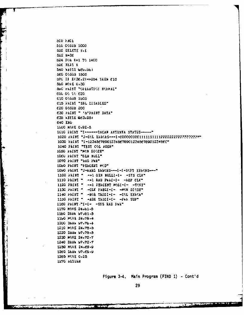
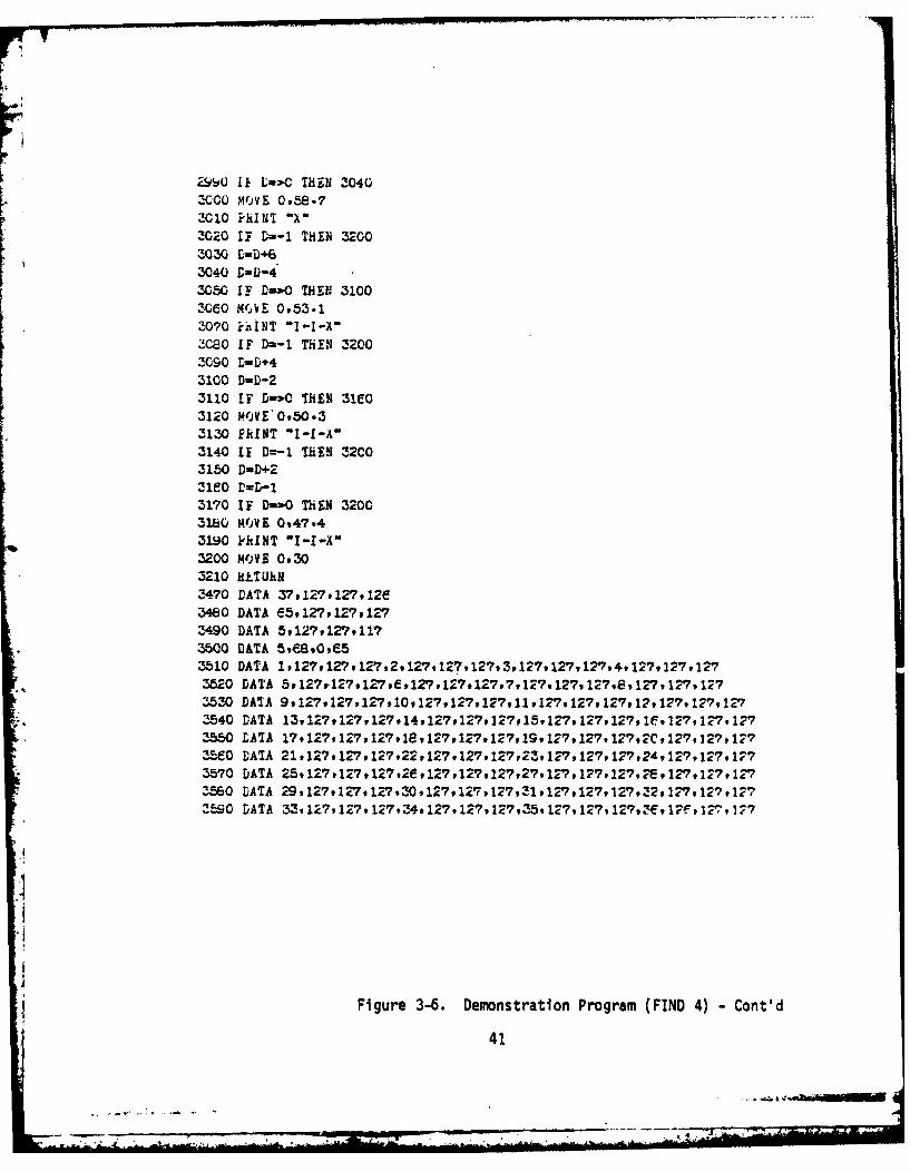
3.8 Software
A complete listing of all program software is shown in Figures 3-4
through 3-6.
r
27

4 'rkE 3'?U 7
C GO TO, 1CC
G( 1( 5CO1Z 1-AGE13 hi=3
14 isiklE t379101:
1f rAGL17 WEYIE CG37 9 b0:18 GO TO 157520 Gb 0 Tb 43C0100 i-AGE
116 k-hIN1 J-1Ib hUN -TESTS# U/D KF1:"
115 G'OSUB k2U120 IBNU
130 Wb'lE, C37910G:
135 Ml~ 637 . b:14b SET KEY
147 IF h-3 ThIN 3C0150 ON Ski- THLB 1701E0 WAIT16!5 GO IT; 16017C eO(LL F#G;5ipl1LC0 GO TO F OF X0190 END200 khINT 'J-Tb; CONTINUF9 U/D KE'!:'210 kI-IIT" - '1'EXECUTIVE"220 khINT m '2' STATUS TEST'
*230 1-hINT - '31BITE TEST-*240 khINT " '4'DME ONLY"
250 hk.TUhN300 PAGE320 GOSUB 1000330 ]DELETE N.E340 N!=1~35 WEITE 1&16925:3t(, 'aBYTE CE6ov97:370 GfOSUb 1500360 GOSUB ;M0390 11 R-3 ThEr, 430400 %BYTE Q37.997:410 WBYTE Ge3995:420 GO TO 6154 430 ?R~INI "ALL').' FIC P~h SUP* SYS HiAD P1-R
440kXIT "l~hSSU/r KEY'11 TO FTSIT450 *All
Figure 3-4. Main Program (FIND 1)
28
bCO )rAG k
510 GOSUB 10c0520 DELETE NE
524 F',h K-1 7Tf 14C0bge NEA1 K540 iblll #Ae~oip:bEO G'iSUb 1500b7C 11 E(3E92)4zw5'4 IiEb elO560 N'jli C9305oC k'hLNT "fAkkhATIf." N'A:IAL"
e10 G4'~bUE 2bCQE15ikINI "SEiL IISABLEZLE20 GOSU~d 200'E30 k'hINT "'5'PhINT DATA"C355 iDlll 4e3995:640 E111;1000 MKIJY 0,92.81010 Hi1iiT I1----TACAN ANIINKA STATUS--1020 ik1NT "J-CrL EhRA.S---I CQCO~I 12112222 3'1030 id N' 1-12'-345C7e9012',45e7eC (I12345E?890 I2!JMC'1040 PRINT "TEST COjL ADDJR"1050 k'kU4T "K.A4 DI'jLK"t10CQ rkklT 'GkN NULL"1070 khuNT "IWAD ziitl~bO PluM'! EiuCIT MIA'1090 khIINI "J"hAhi LhktRS-I -I-Sf,FT EBH(,RS---'1100 tirkN " -3-1 GIN NULLI-I- -SYS CLK'1110 khINT -3-1 RAD PkkI-I- -hEF CLK"1120 PRINT " -3-1 M~CENT MOD1- -TCKlI113C zPuINT 0 -CLK FkEGII1 -10AN DM'.DE"1140 khul'ft -NORk ThIGI-1 -CtjL [Rk"llbO HukbI f -AUX ThIGI-I- -EFuI SUP"11COihLT"t[ -SYS HAD liii1170 NOVE 249b1.5
11W KV k 24P78-41200, D AW 9t,841210 NOV E 24975.b1220 DRIAW W756
A1230 MOiVE 24#72.71240 DIkA% $097
120MI 4e-12tO0 DhAW V?#CS'.h91205 VfAVE 092512'70 hilUhN
Figure 3-4. Main Program (FIND 1) -Cont'd
29

15CL LIM IAN94)iblL F'I.;h I11 T'.) N
153b If A~lkb THEN 15751540 11 A:-E4 THEN 15b51545 IF NJ=W ThEN 163015bO A=A+l1b55 GO 70~ 1E30
1580 GO 10~ 1590156b i-hlN1 "BTE CLK EE'
1-9 N-1
1600 EftL
1640 C-APSVEI.Z5))IE50 L=AbS(E(I*4))1660 k1=30.5+A*1 .7921670 MO.VE P9,81.9i
11E90 G(OSUE 200017C0 NEXT I1720 XETUN.2000 If B-255 ThEN MO92010 E-B-2242020 IF B-l-0 THEN 20702C30 MOVE TP,75.62040 PRINT "X'20C0 B-b+322070 i=B-16Z080 11 B-o0 THIN 21302090 MOVE P9,702100 PUINT "X"2120 B=E+1621-10 B---82140 IF B-P0 THEN 219C2150 MOVE Ps,72-621f0 k'hINT "X"2160 k-b~b210 b- B-42200 IF B-.,P THEN 22502210 M"OYi 0944-7
*2220 PUN1T "1-I-X"2240 B-h4
2250 B-B-22260 IF B-0 THEN 22902270 WKE 1,78.5;:280 k'hINT "
2290 REM~lN
Figure 3-4. Main Program (FIND 1) -Cont'd
30

5C It C-k5b Thi~N 2E!50* 510 C-C-224
2520 If C-0G ThEN 257025-'0 MOIk OICl.5
25EO C-C+322.570 C=C-ie256C IF C-o0 ThE)N 2E302590 MOAE 0055-92COO khIN I -I-A"
Z2Z0 C=C+16
2C40 IF C-0 ThEN ZE~0ZE50 MOjVE 0,47.42CeO k-kINT "X"zebc c-C's2ES0 C=C-4Z7CC IF C--a0 ThN 275102710 MOVE C,50.3272C PINT "X"Z740 C=C+42750 C=C-227CC IF C-2,0 THEN 28102770 MOUi 0953-12780 PRINT X28CC C-C+Z2610 C-C-i2620 11 C-0 THEN Z650283D WOVE 0,58.72b4G PhIZIT --2&%~ IF D-255 TbEff 32C286C Lo-D-2242670 IF D-.,0 TKEH 2920k6bO WAK'E 0961-5
*2E90 PhINT "k2910 tL-D+35225,20 Du-iCZsO IF D-o0 THEN 29602940 Mr)VE 0,55-92950 khINT "X".2970 D-D+le2!,0 L-iD-b29So0 IF Da-0 ThEN 2040
Figure 3-4. Main Program (FIND 1) -Cont'd
31

ZQ lb rr'INI -X"
3040 D=-L-4X 50 IF L,='0 ThiN 3100
3C~CM(~L0953-1
Z1070 kINWI1-I-A"
3C0 D=L+4
3100 D=L-23110 Ik L=-". W1EV 31603120 MOVE 095C.331Z0 PhINT -1-I-X"3150 L=D+2
31EC L=D-13170 11 U=z-0 ThEN 32-00
318U MfjVE 0#47-431Y0 PRIdT "I-I-X"
Z200 MUEF 0930
3210 hElhkH4Z00 FIND 34310 WhITE N4320 F~ih 1-1 TOj N4330 WHITE EU,1I ,FAIp2)vE(I932 ,E(jqAI
4340 NEXT I
4ZbG FlhI) 243e0 OLD
Figure 3-4. Main Program (FIND 1) -Cont'd
32

4 Gt('.ub 100
(z iLtD
100FIINL2105 hLAD 633:N110 LIM L(Nv4)120 FORA 1=1 TO~ N130 EDC3EI1,(I2,(.IU4140 NkXT I150 iN! 441915:1501eQ kbINT ra379;EE:l170 PRINT 441:"J---- TACAN ANTINKA STATUS---"180 Jt4' J-1 Tr N190 IF~ EIJvl),cY7 TbEN 220195b IF E(Ji1),126 ThEW E9C200 ?R~INI (941:OPITE CLVCK FAILUFF"210 G'i Tf; EEG220 NEXT JZZ0 IF LIN, '-cz2.54 ThLK 2EC240 khiINT 441:"OERATION2 N..RMkAL"250 G(O To EOZED PHuNT b41:'J---COLUMK ERhf'.RS"270 kiINT 0i41: USING 20:"TCA,9GM"9hhD"PEC'E"Y-i260 PRINT @41: USING 290:".ULP"~ID29'0 114ACL SISAl300 J1h 1-1 TO N305 IF N-i THEN 320W07 IF lw3e THEN 320310 IF E(192)3-253 THEN WEO320 FinE(I,21-224330 GEOSUB 10CC340 PRkINT 041: USING 36O:E(I,1)9AS9C39?lvDl350 IMAGE 2D.1OTv.4feA)360 NEXT I370 GOjSUP 2000
I390 If CiO0 THEN 410400 PRINT 641:"31 CO~L GEN NULL-410 11 C3w0 ThEN 430420O PRINT 641:0"2-.COK. EhD PWRO
Figure 3-5. Print Program (FIND 2)
33

) ~1U F:01=F-2
1240 IF Is=>0 ThEY! 12601250 D$='"
12e0 I-f+2
127C GO 10 12S0l kbo Ds " "I
1290 F-1-1
13C0 I 1=0 THIN 1330
1310 A e1
1320 GO TO 134013-0 AC-=140 hElh2OC0J F=E(N,3)-224
2010 IF '=,,0 hEN 20e0
2040 F-F+32
2050 GO TrO 2070
2060 B1=02070 F-F-16
Z(b, IF T=0 ThEN 21202C.*C h2=i
2100 ,-F+lf
2110 GO TO 21302120 B2-0
k1l3 FI-F-
2140 IF I,-0 THEN 21602150 B3-1
2160 -F4B
2170 GO TO 2190
2160 B3-0
2190 F-F-42200 IF F--0 ThEN 22402210 B4-12220 F-F+4
2230 GO TO 2250
2240 B4-0
2250 F-F-222e0 [F F-3-0 THEN 23002270 B-0-12280 -F+2242-0 Go TfO 25102300 B5-02310 F-F-12320 [F F-0 THEN 2350Z330 E162340 GO Tf; 23602350 M-0
Figure 3-5. Print Program (FIND 2) - Cont'd
34

4Z0 If C2-0 TBEN4 45044C PRhINT Q41:"3- COL 1-lhC "4501 FB5=0 THI! 470
47C 1) B4-0 IhE1h 490460 1-hINT 64W:"dA TlIC'
500 k'kIN' C141:AUX TRIG"510 khlNT Q41:"J----SlrFT EhR(IS"510 IF bl-C THEN 54C5W0 1-INT 441:"SYS CLK'540 IF BE-0 Iii 11 SCa55(J khINT 441:'hEF CLK"5E0 IF B2-0 THEM 560570 1-hINT 441:"TNE'bi&-O IF C4-0 ThER ECc
tZ(, IF CE-0 THEN IE40EZO k-hINT 041:FPWR SUP-'C40 I) A4-0 THEN EEOEbO 1-hIST (&41:"SS hAD -rl1iEEO PRhINT U41:"J---EXD QJ DATA---"M? 1kRINT F&3792E:C
e90 1-LINT 041:"LME 'AlLY MODE"700 00 TG EEO1000 It F-m-O ThEN 10401010 As-"X1020 F-F+32
*1030 GO TO 10501040 AW "1050 F-F-1C1GEO 1F F-~0 THEN 11001070 B=X"1060 FFle10 to GO TO 11101100 bs-0 -
1110 --1120 IF F=-0 THEN 1160
1130 CS-*"1140 1-F+6
1150 0'; TO 1170*1le 11C$c-"
1170 FinF-41160 If F-.,w THEN 12201190 A4-11200 1-1+41210 Gb. T'; 12301,,nAA£M(I
Figure 3-5. Print Program (FIND 2) -Cont'd
35

2370 I Fw'O T IIE 2410
2360 dmI1
,4C0 GO Tf( 2420
2410 Cl-0
2420 -i-lfE
2430 U 1I,0 ThP2N 24 70
k440 C2-1Z450 F-F+e24C0 GO TO 24602470 C2-O2460 F-k-6
2490 IF F-0 ThEN 25.Ok5oo C-M.12510 F +6
2520 GO TO .5402530 C3-m02540 J-F-42550 I -I=0 THEN 259025e0 C4-1k570 F-i+4
2bW0 Gj V) U~0025 C4-02F.00 IF--22C10 IF F-I0 THEN 2e502620 CS-12E30 F-F+22e40 GO TO 2eEo2,50 CS-02660 f- -12'70 IY 1=30 ThEN 27002680 CE-1
2690 GO TO 27102700 C-0
71C IULT WiN
Figure 3-5. Print Program (FIND 2) - Cont'd36
SI. lI. . . . I

---i ANTEC---
4 INIT5 kAGEcSET KEY
7 GO [0 1008 GO TO 500
12 G ., TO 70016 RESTOihE 3490
17 GO '10 300
20 KESTOIhE 3480
22 GO TO 300
24 PAGE25 kkINT "DME ONLY, SEQ DISAPLF:D"26 PHINT "DEPRESS U/D KEY'1' T(! RESET"2 EN C2b hESTOjRE 3470
29 GO TO 300100 -ikN "EXECUTIVE, SRf. ENAELE "110 PhINT "J-TO RUN TESTS, U/D KEY:"120 GfJSUB 240130 ON SRQC THEN 160140 14AIT150 GO TO 140160 POLL EE;5,1170 GO TO E OF 300
180 iETUiN190 E?.D200 PRINT "J-TO CONTINUE* U/D KEY:"210 PRINT 0 'V'F.ECUTIVE"240 PRINT '2'STATUS TEST-NOWAL OPR"260 PRINT '3'BITE TEST"270 PRI!lT '4SIMULATED COLUMN FAULtT280 PitINT " '5'SIMULATED BITE CLK FAULT"285 PRINT " 'E'SIMULATED DNE ONLY"
287 PhINT '7'SIMULATED NON-COLUMN FAULT"290 RETURN200 IAGE
320 GOSUB 1000330 DELETE N.E340 Nal
370 GOSU 1500380 GOSUB 2500390 PRINT "SRQ DISABLED"
400 GOSUE 200410 END
Figure 3-6. Demonstration Program (FIND 4)37

500 rAGE
510 G(0SUB 1000520 DELETE N.E
5-0 N-o-540 hESTOhE 3510
bSO 1OK J-l TO 1000555 NEXT J5oE G(%SUB 1500570 GOSUB 2500560 GOSUB 1600
590 GOSUB 200
E0U END700 PAGE720 GOSUB 1000730 DELETE N.E740 N-1
750 RESTORE 3500770 GOSUB 1500780 GOSUS 2500790 i'RINT "ALL'X' EXC PVIV SUPSYS PAD PWP"600 ihINT "DEiRESS U/D KEY'1' TC RFSET"810 END1000 MOVE 0,92.51010 PRINT 'I- TACAN ANTENNA STATUS----
1020 PRINT "J-COL ERRf-RS--1-0000000001111111 1 1222222227'l' N779"
1CSO PRINT "I-12345?ED8O12".345e7e90123458e69OI2345EC"
1040 PRINT "TEST COL ADDR"1050 PRINHI "140% DIO01"
10CO PRINT GOEN NULL"1070 PRINT "RAD PWR"
1080 PRINT "PERCENT M(JD"1090 PRINT "J-iARD ERRORS- I-SOFT ERR¢RS--"1100 PRINT - -3'1 GEN NULLI-t- -SYS CLK"1110 PRINT " -21 RAD PWRI-I- -REF CLK"1120 PRINT -.-1 PERCENT MHODI-I- -TONE"1130 PRINT -CLK FEC-I- -MWN DIODE"1140 ikRINT " -NOR TRIGi-I- -COL ERROR"1150 PRINT a -AUX TRIGI-[- -PWR SUP.11CO PRINT "I-I- -SYS RAD PWV"
1170 MOVE 24,81-51180 DRAb 97,61.51190 MOVE 24,78.41200 DRAW 97,78-41210 MOVE 24,75.51220 DRAW 97,75.51230 NOVE 24,972.71240 DRAb 97,72-71250 MOVE 249C9.912e0 DRAW 97te9.9
1270 kETURK
Figure 3-6. Demonstration Program (FIND 4) - Cont'd
38

15(0 FOh Iml To N1520 READ AtkC#D
1540 IF A'-6h THEN 1660
1500 MOVE 0,301560 irkINT "BITE CLX ERR"15"70 khINT "E khESS U/D KEY'1' T'; MESET"
1560 ND1660 P30-b-A*i-792I670 MOVE P961#9lEcO iktINT "t"1EO GOSUB 20001692 FOr J-l T0 200
1694 nEXT J1700 NEXT I1720 RETURN
1800 MOVE 0,401610 IT -Bz-0 THEN 18031620 AhINT 0OPERATION NORMAL"I 25 iRINT -SRG DISABLED-
16:30 HETU0k:2000 IF B-127 ThEN 22902010 B-B- t62020 I) H-,.0 ThEN 2070
2030 MOVE P,?5.62040 PRINT OX"2050 II B-1 THEN 22902060 B=B+322070 B=B-162080 IF B=zO THEN 21302090 MOVE i,702100 PRINT "X"2110 IF B-I THEN 22902120 B-B+ 62130 B-E-62140 IF B-0 THEN 21902150 MOVE iP,72.82160 PRINT "X"2170 IF B--i THEN 22902180 B-B+e219C B-B-4
2200 IF 3-0 Th EI 22502210 MOVE 0,44.?2220 kRINT "I-I-X"2230 IF B-1 THEN 22902240 B-,.422-10 B-B-22260 IF P-,0 THEN 22902270 PrO;E k ,78.52280 PRINT "X"
2290 kETUHIi
Figure 3-6. Demonstration Program (FIND 4) - Cont'd
39
. . ... ,_, an % _ :.. . .. . . . ..- . .. ".% . ,... _ " . . . . . " " - ' ll :"'" ' " '"' . . .. -- ' ' ' "
.r. ,ql ~ -'iet - .'21.. ...7

25CO IF C=127 THE: 28502510 C=C-'E2520 IF C=0 THEN 25702530 MOVE 0,f.-52540 PRINT "I-I-X"2550 IF C--i THEN 285025O C=C+322570 C-Cle
2 .0 IF C-0 THENe 2E3O2590 MO(VE 0,55.92 00 k'hINT "I-I-X"2E10 IF C=-i TBIN 28502e20 C=C+lE21E30 C=C-6Ze840 IF C-.v0 THEN 2E902650 MOVE 0,47-42M0 khINT "X"
2e70 IF C--i THEN 2e502680 C=C+8
2690 C=C-4
2700 IF C=0 THEN 27502710 MOVE 0,50-32720 PRINT "X"272C IF C--i THEN 28502740 C-C+4
2750 C=C-2
27e0 IF C=20 ThEN 28102770 MOVE 0,53-12780 PRINT "X"2790 IF C-l THEN 28502800 C=C+2
2810 C-C-i2820 IF C-0 THEN 2850
2830 MOVE 095872840 PkINT "I-I-X"2850 IF D-127 ThEN 320028eO DD-962b70 IF >2O THEN 29202860 MOVE 0,ei.52890 PhINT "X"2900 IF l - THEN 32002910 D-D+322920 D-D-le2930 IF D-3-0 THEN 29802940 MOVE 0,55.92950 PRINT OX"29e0 IF Di-i THEN 3200270 D-D+Ie29b0 D-D-6
Figure 3-6. Demonstration Program (FIND 4) - Cont'd
40
ZCCO MO.VE 0956-7
'00IF D-- THEN -1400
300D-D-43CGIF D-0 THEN 310
r3070 ?1,INT -11X-:5140 IF D-- 'ThEN 320
W910 D-D+43100 D-D-13170 IF D-30 THEN :5200
3120 t4(JVE* 0332110 PITI-M40 IFDATARE 3712.2,13150 DAT 6D 2717,2
3490 DAIT 5,12-12- 113200 MOVA 09380,6
"3470 DATA 379127#127#127e,2,2,2?,?.?17a1717173480 DATA 69127#127914-70171?1?112,7171,2,1',v340 DATA 53127127117.1,2,2,2,51717171,2,2.
3510 DATA 117.27,2722127127127,9279127,112727,24,9127,127.23570 DATA 5,27,2717,26,27,271272712 1212727,2*12-7,-127,23560 DATA 9127127127.30,27,2?,127,31,12791279127.32, 127127173540 DATA 1312791279127,34,127,127,127,35,127,1l27,127,9E12127,Ie7927
350DT 7171A929el7l7l~l92,2929Cp29,c97
Figure 3-6. Demonstration Program (FIND 4) -Cont'd
41

4.0 ANTENNA GROUP TESTS AND INSTALLATION
4.1 Acceptance Tests
Following completion of all modification, the antenna group was
subjected to a complete acceptance test. This test was in accordance with
Rantec documents 11002-ATP and 11016-ETP. The test report was furnished to
the FAA as a part of Progress Report 4 (Rantec No. 11016 PR4).
4.2 Installation
The antenna was delivered to the FAA test center at Atlantic City
and following the arrival of Rantec personnel, was installed at a VORTAC test
facility. The antenna was installed on top of the existing VOR cone (see
paragraph 6.d).
The modulation generator interconnecting cables and r'f cable were
routed through the VOR cone down into the equipment 7-oom. The modulation
generator and test set were installed at a temporary location within the
equipment room.
All equipment was then interconnected and the complete TACAN
system was turned on. It was discovered that noise was causing a problem
with the monitor-diode BITE circuit. The low pass filter on PCCIA2A22 used
with the monitor-diode bias-level detector was modified to decrease its knee
frequency. This cured the problem and will not effect the failure-detection
capability of that BITE circuit.Since no external monitor equipment or flight-check aircraft were
available, no system test could be performed.
It was noted that the antenna monitor circuitry indicated an
occasional antenna fault; however, the fault never persisted long enough toobtain column-related data on the test set. It was believed that the problem
was associated with the monitor circuit and not the actual radiated signal.
An attempt was made to fix the proo sm by reseting the low-percent modulation
i level comparator. This had only marginal success.
42
- *- " - - " .. ... . - *! [

Since this problem was not encountered at Rantec, it is believed
to be the result of system noise getting into the antenna monitor lines. A
second PCCA22 was fabricated at Rantec incorporating a digital circuit to
eliminate monitor sensitivity to short term noise bursts. Unfortunately the
PCC could not be fully checked out at Rantec and was found to be inoperative
at the FAA test center. It is felt, however, that the design is solid and
should be incorporated in future modulation generators.
5.0 CONCLUSIONS
The modified TACAN Antenna Group has met the initial requirements
of the program and now awaits test and evaluation at Atlantic City. It is
believed the antenna group will meet all FAA requirements both with respect
to performance and the operation of the newly designed interface.
43

6.0 RECOMMENDATIONS
As a result of the initial operation and installation of the TACAN
antenna group there are several areas which need to be dealt with in an FAA/
RANTEC design review meeting.
a. Upon initial turn-on the modulation generator comes on in the
DME-ONLY mode. Initialization of full performance requires that the controller
(test set) be connected and placed in its EXECUTIVE mode. It may be desirable
that power-up of the system not require computer intervention. Such a change
is very minor in nature.
b. There is some doubt that the Second Generation VORTAC requires
a bipolar TONE signal. If this is the case, that circuitry and its associated
BITE can be removed from the modulation generator.
c. The modulation generator meets the requirements of the IEEE-488
bus. The use of this interface with the VORTAC system will require program-
ing of that system computer. The programing now accomplished in the test set
should prove useful as a guide for that purpose; however, an interface between
Rantec and the beacon system programmer should prove most beneficial.
d. The antenna connectors are presently located on the side of
the antenna. For installation on the VOR cone, it would be desirable that
these connections be made on the bottom of the antenna. At Atlantic City a
hole was made through the adapter ring to accomplish the required cabling.
It is desirable, of course, that the solution to this problem be made in a
way which does not impact the antenna seal.
e. Some system of ordering the antenna/modulation generator inter-
connecting cables is required. It was noted in Atlantic City that at least
three different installation configurations exist which will require different
cable lengths.f. Incorporate a noise immunity circuit in the antenna monitor
electronics (see paragraph 4.2).
44

Since this problem was not encountered at Rantec, it is believed
to be the result of system noise getting into the antenna monitor lines. A
second PCCA22 was fabricated at Rantec incorporating a digital circuit to
eliminate monitor sensitivity to short term noise bursts. Unfortunately the
PCC could not be fully checked out at Rantec and was found to be inoperative
at the FAA test center. It is felt, however, that the design is solid and
should be incorporated in future modulation generators.
5.0 CONCLUSIONS
The modified TACAN Antenna Group has met the initial requirements
of the program and now awaits test and evaluation at Atlantic City. It is
believed the antenna group will meet all FAA requirements both with respect
to performance and the operation of the newly designed interface.
43
I .- A -,

6.0 RECOMMENDATIONS
As a result of the initial operation and installation of the TACAN
antenna group there are several areas which need to be dealt with in an FAA/
RANTEC design review meeting.
a. Upon initial turn-on the modulation generator comes on in the
DME-ONLY mode. Initialization of full performance requires that the controller
(test set) be connected and placed in its EXECUTIVE mode. It may be desirable
that power-up of the system not require computer intervention. Such a change
is very minor in nature.
b. There is some doubt that the Second Generation VORTAC requires
a bipolar TONE signal. If this is the case, that circuitry and its associated
BITE can be removed from the modulation generator.
c. The modulation generator meets the requirements of the IEEE-488
bus. The use of this interface with the VORTAC system will require program-
ing of that system computer. The programing now accomplished in the test set
should prove useful as a guide for that purpose; however, an interface between
Rantec and the beacon system programmer should prove most beneficial.
d. The antenna connectors are presently located on the side of
the antenna. For installation on the VOR cone, it would be desirable that
these connections be made on the bottom of the antenna. At Atlantic City ahole was made through the adapter ring to accomplish te required cabling.
It is desirable, of course, that the solution to this problem be made in away which does not impact the antenna seal.
e. Some system of ordering the antenna/modulation generator inter-'1 connecting cables is required. It was noted in Atlantic City that at least
three different installation configurations exist which will require different
cable lengths.
f. Incorporate a noise immunity circuit in the antenna monitorelectronics (see paragraph 4.2).
44

Since this problem was not encountered at Rantec, it is believed
to be the result of system noise getting into the antenna monitor lines. A
second PCCA22 was fabricated at Rantec incorporating a digital circuit to
eliminate monitor sensitivity to short term noise bursts. Unfortunately the
PCC could not be fully checked out at Rantec and was found to be inoperative
at the FAA test center. It is felt, however, that the design is solid and
should be incorporated in future modulation generators.
5.0 CONCLUSIONS
The modified TACAN Antenna Group has met the initial requirements
of the program and now awaits test and evaluation at Atlantic City. It is
believed the antenna group will meet all FAA requirements both with respect
to performance and the operation of the newly designed interface.
43
II
*1!

6.0 RECOMMENDATIONS
As a result of the initial operation and Installation of the TACAN
antenna group there are several areas which need to be dealt with in an FAA/
RANTEC design review meeting.
a. Upon initial turn-on the modulation generator comes on in the
DME-ONLY mode. Initialization of full performance requires that the controller
(test set) be connected and placed in its EXECUTIVE mode. It may be desirable
that power-up of the system not require computer intervention. Such a change
is very minor in nature.
b. There is some doubt that the Second Generation VORTAC requires
a bipolar TONE signal. If this is the case, that circuitry and its associated
BITE can be removed from the modulation generator.
c. The modulation generator meets tne rejuirements of the IEEE-488
bus. The use of this interface with the VORTAC system .ll require program-
ing of that system computer. The programing now accomplished in the test set
should prove useful as a guide for that purpose; however, an interface between
Rantec and the beacon system programmer should prove most beneficial.
d. The antenna connectors are presently located on the side of
the antenna. For installation on the VOR cone, it would be desirable that
these connections be made on the bottom of the antenna. At Atlantic City ahole was made through the adapter ring to accomplish the required cabling.
It is desirable, of course, that the solution to this problem be made in a
way which does not impact the antenna seal.
e. Some system of ordering the antenna/modulation generator inter-
connecting cables is required. It was noted in Atlantic City that at least
three different installation configurations exist which will require differentcable lengths.
f. Incorporate a noise immunity circuit in the antenna monitorelectronics (see paragraph 4.2).
44

7.0 REFERENCE DOCUMENTS
The following documents are referenced here as applicable to this
project:
Statement of Work - Department of Transportation (DOT)
Contract No. DTFO1-8O-C-10148
Technical Manual - OE-258/URN TACAN Antenna Group
Rantec Document No. 11002-TM-C
Technical Manual Addendum
Rantec Document No. 11016-TMA
45
IJ

APPENDIX A
ANTENNA FAULT TESTS
In an effort to gain further insight into antenna group performance
as a function of various faults, a series of patterns were obtained for the
135 Hz phase-track (bearing) error, using various faults. These tests were
performed in Rantec's 120-foot anechoic chamber using the specialized test
equipment designed for TACAN antenna acceptance tests. Patterns are shownin Figures A-1 through A-12. The following description deals with these
patterns:
A-1 Normal pattern.
A-2 Gain of drive amplifier changed slightly - no
significant pattern change.0i
A-3 Short output of drive amplifier - ±20 peak error
on either side of faulty drive.
A-4 Short PIN diode modulator - ±20 peak error on
either side of shorted modulator.
A-5 1K resistor across PIN diode modulator (test of
PIN diode leakage) - no significant change.
A-6 IOO2 resistor across PIN diode modulator
(increased leakage) - ±20 peak error on either
side of affected modulator.
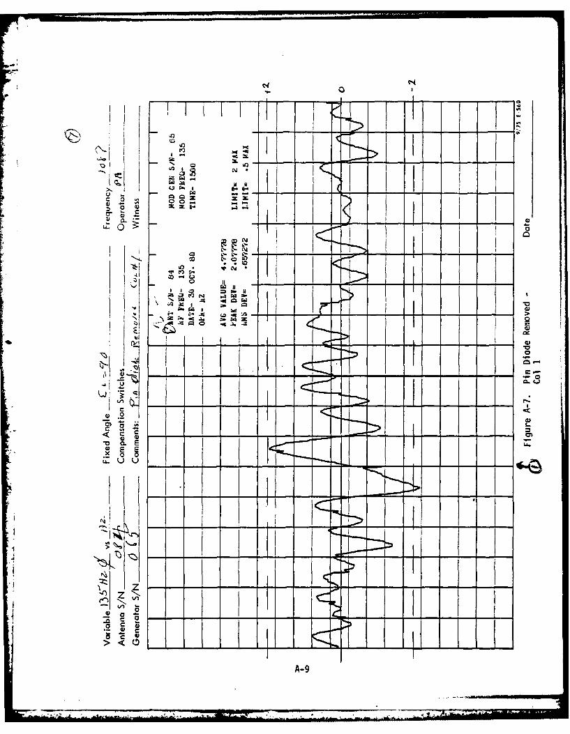
A-7 PIN diode removed (open) - ±20 error on either
side of affected drive.
A-8 RF cable removed (no carrier) - ±20 error on
either side of affected column.
A-9 Adjacent PIN diode shorted (two column error)
±2.50 error on either side of adjacent column.
A-1
• ' A II -
A-10 PIN diodes shorted, two columns 300 apart (twocolumn error) - ±2.20 error over broader section.
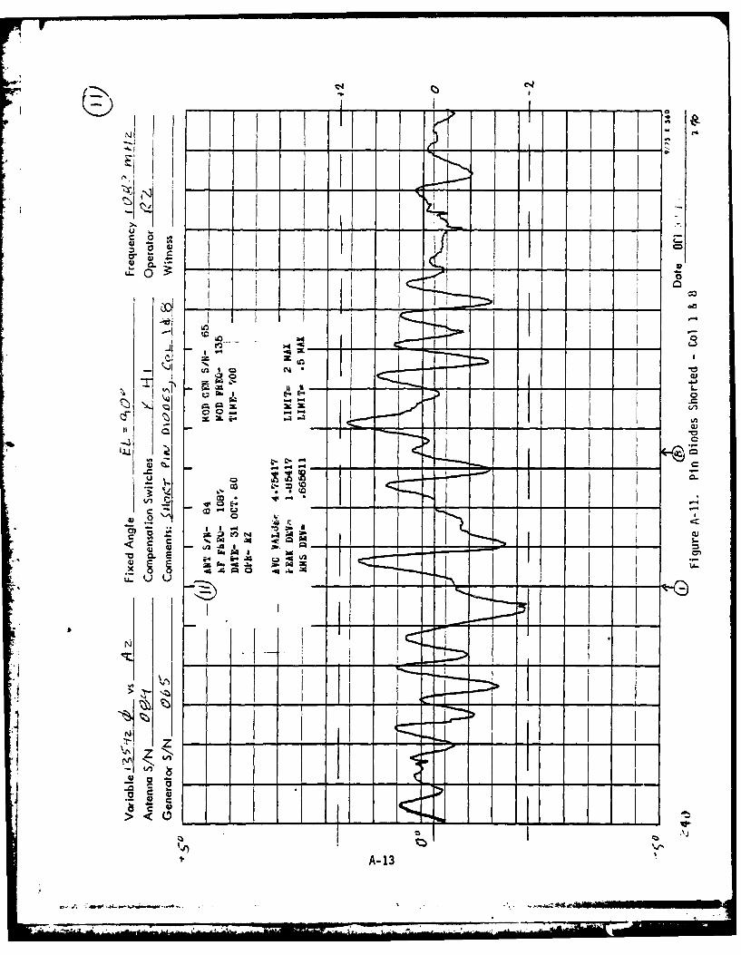
A-11 PIN diodes shorted, two columns 800 apart+-1.80 errors at both columns.
A-12 PIN diodes shorted, two columns 1800 apart(both outputs of one push-pull modulator) -
-t2.20 error with roughness throughout pattern.
II
A-2

I 0
cr cIXIU o o , I -. , .
43
I I I
"I
o I
I ** - . - -1
- ' - ITI
A--
. _ 4 C, L .. . .-'-i
43 E E*x 0 0
-- U U
IQI
-~A--

I I I 4
10 II I.
c _-
U3 Ia 1 .4 -
.1 It
U-0 CL Vt-T.~
'A-4

7Qf L1OI
Is-
c41
i-K 0
o o" ' a I I I
itI "
t u
~A-5

iN
F1ctt
' 'I I I ,- - -I j -
, ,.. II I
ol
I +KT>° I I
0 Iz I
'I-
,ucu
I4 1
' 4 - hi .iI' L J' j'
CL
C0L
A-6-
- I Im
i ' + -
A-6i IL .
:izt._'-

tlI:21'N I- -I- - -6
N I Si
I-S
r. C IA ! 'AXN
U- 0 N 114 -
U0 c- -* C1
L2 .4
x 0 0
ul
>~~-I- -
A-7-

4 -4 1
&L -
;
II +70 0 0,
CCD
EI E0
.2 o
u +>C
Ao 8
' ,-iii I
-J , -,... j . ,A-8~zI
- -
chi
-a I.
_o I 4 1 __ _ _ _
* * I i I
tI
I I I
U- U U
I
I 1C
A-9
~2KI

C4.
II
r _. ..~ ~ . -..........
' * ] ' [ I ' *f "
. .
C.-. , -II Ii'
_o liltI
icl
P~.6j
a -
I I-°
4 1 : - (* 24 II °SI V I 1 I , .
_ _
A-0 -* I Ii 0 I-
I' U - I
I I " 'i
i ia-i I
° C --
>I I I -, , ! ' I I
A-lO
4 . n

N> cd
W :-- 4--a Q ~a I-
- E-. l
0 0-
u I
_I
IA-11

0t-
-,,
4.nI i
U ~ wa
.. I
4
40's
LAA
~~dA 12 . -
-- I-
I I
Lo__ I _
.LI z
3 -4- Al
MI 00 E W
u~ u E--04U
a a* -
IT 3 I I 1~ "
.A- 1

cri M
~~L.
0 7,
'o
-7. -4-.
InIC-~~A 14. . I

I