electric circuits tutorial problems - urząd miasta Łodzi tutorial problems.pdf · electric...
TRANSCRIPT
Michał Tadeusiewicz
Electric Circuits Tutorial Problems
International Faculty of Engineering Łódź, 2010
3
DC analysis Question 1
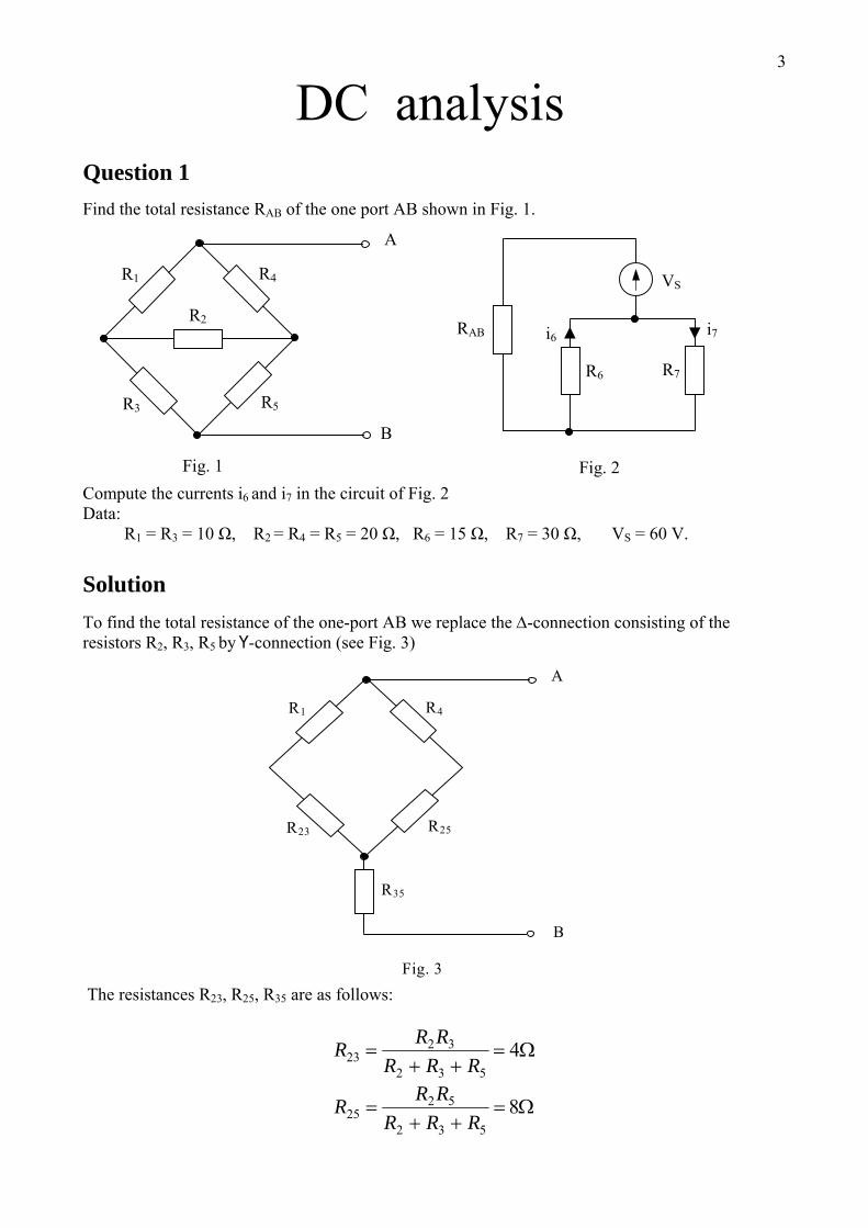
Find the total resistance RAB of the one port AB shown in Fig. 1.
R7
RAB i7
B
A
VS
R5 R3
R2
R4
R6
i6
R1
Fig. 1 Fig. 2 Compute the currents i6 and i7 in the circuit of Fig. 2 Data: R1 = R3 = 10 Ω, R2 = R4 = R5 = 20 Ω, R6 = 15 Ω, R7 = 30 Ω, VS = 60 V. Solution
To find the total resistance of the one-port AB we replace the Δ-connection consisting of the resistors R2, R3, R5 by Ү-connection (see Fig. 3)
R35
B
A
R25R23
R4R1
Fig. 3 The resistances R23, R25, R35 are as follows:
Ω=++
= 4532
3223 RRR
RRR
Ω=++
= 8532
5225 RRR
RRR
4
Ω=++
= 4532
5335 RRR
RRR
Hence, the total resistance is
( )( )Ω=
+++++
+= 33.13254231
25423135 RRRR
RRRRRRAB
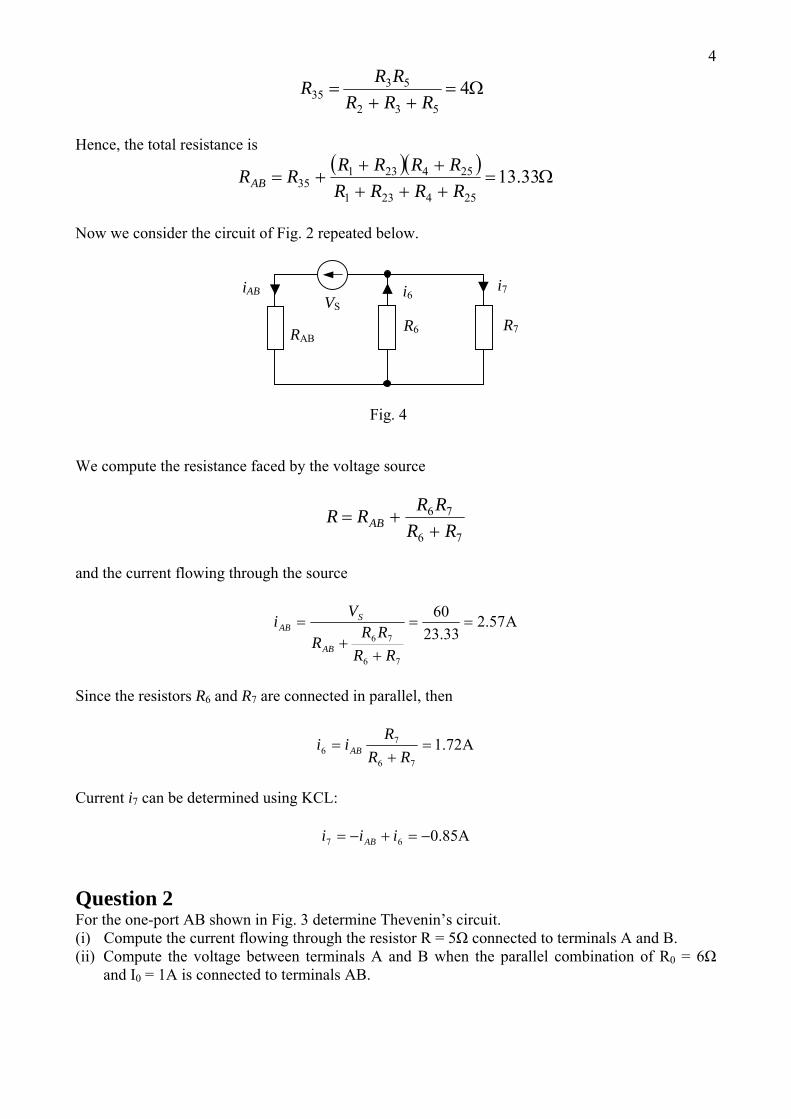
Now we consider the circuit of Fig. 2 repeated below.
iAB
R7 RAB
i7 VS
R6
i6
Fig. 4
We compute the resistance faced by the voltage source
76
76
RRRRRR AB +
+=
and the current flowing through the source
A57.233.23
60
76
76==
++
=
RRRR
R
Vi
AB
SAB
Since the resistors R6 and R7 are connected in parallel, then
A72.176
76 =
+=
RRR
ii AB
Current i7 can be determined using KCL:
A85.067 −=+−= iii AB
Question 2 For the one-port AB shown in Fig. 3 determine Thevenin’s circuit. (i) Compute the current flowing through the resistor R = 5Ω connected to terminals A and B. (ii) Compute the voltage between terminals A and B when the parallel combination of R0 = 6Ω
and I0 = 1A is connected to terminals AB.
5
RE2
B
R0
E1 A
0I
R3
R2R1
Fig. 5
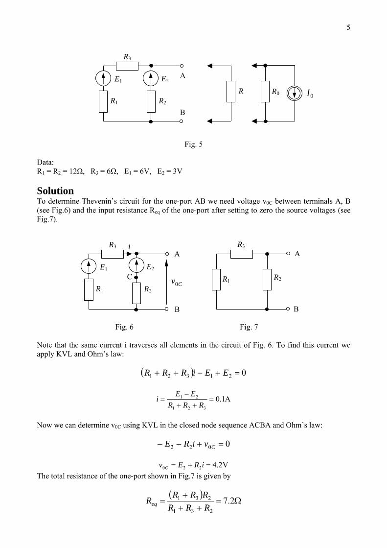
Data: R1 = R2 = 12Ω, R3 = 6Ω, E1 = 6V, E2 = 3V Solution To determine Thevenin’s circuit for the one-port AB we need voltage v0C between terminals A, B (see Fig.6) and the input resistance Req of the one-port after setting to zero the source voltages (see Fig.7).
i
B
A R3
C R1
E2
B
R2
E1
A
Cv0
R3
R2 R1
Fig. 6 Fig. 7 Note that the same current i traverses all elements in the circuit of Fig. 6. To find this current we apply KVL and Ohm’s law:
( ) 021321 =+−++ EEiRRR
A1.0321
21 =++
−=
RRREEi
Now we can determine v0C using KVL in the closed node sequence ACBA and Ohm’s law:
0022 =+−− CviRE
V2.4220 =+= iREv C
The total resistance of the one-port shown in Fig.7 is given by
( )Ω=
+++
= 2.7231
231
RRRRRRReq
6
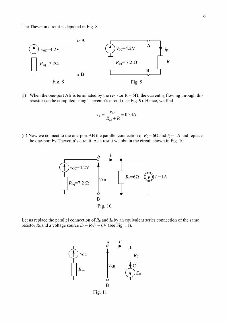
The Thevenin circuit is depicted in Fig. 8
B
AA
iR
B
v0C=4.2V
Req= 7.2 ΩReq=7.2Ω R
v0C=4.2V
Fig. 8 Fig. 9
(i) When the one-port AB is terminated by the resistor R = 5Ω, the current iR flowing through this
resistor can be computed using Thevenin’s circuit (see Fig. 9). Hence, we find
A34.00 =+
=RR
vi
eq
CR
(ii) Now we connect to the one-port AB the parallel connection of R0 = 6Ω and I0 = 1A and replace the one-port by Thevenin’s circuit. As a result we obtain the circuit shown in Fig. 10
vAB
i’
I0=1A
vOC=4.2V
A
R0=6ΩReq=7.2 Ω
Fig. 10 B
Let us replace the parallel connection of R0 and I0 by an equivalent series connection of the same resistor R0 and a voltage source E0 = R0I0 = 6V (see Fig. 11).
C vAB
i’
E0
vOC
A
R0
Req
Fig. 11 B
7Next we compute current i’ using KVL and Ohm’s law:
( )
.A 77.062.762.4'
0'
0
0
00
=++
=++
=
=−−+
RREv
i
EviRR
eq
OC
OCeq
We apply KVL, to the closed node sequence ACBA, and Ohm’s law:
0' 00 =++− ABvEiR
and find voltage vAB
VAB 38.1677.06' 00 =−⋅=−= EiRv
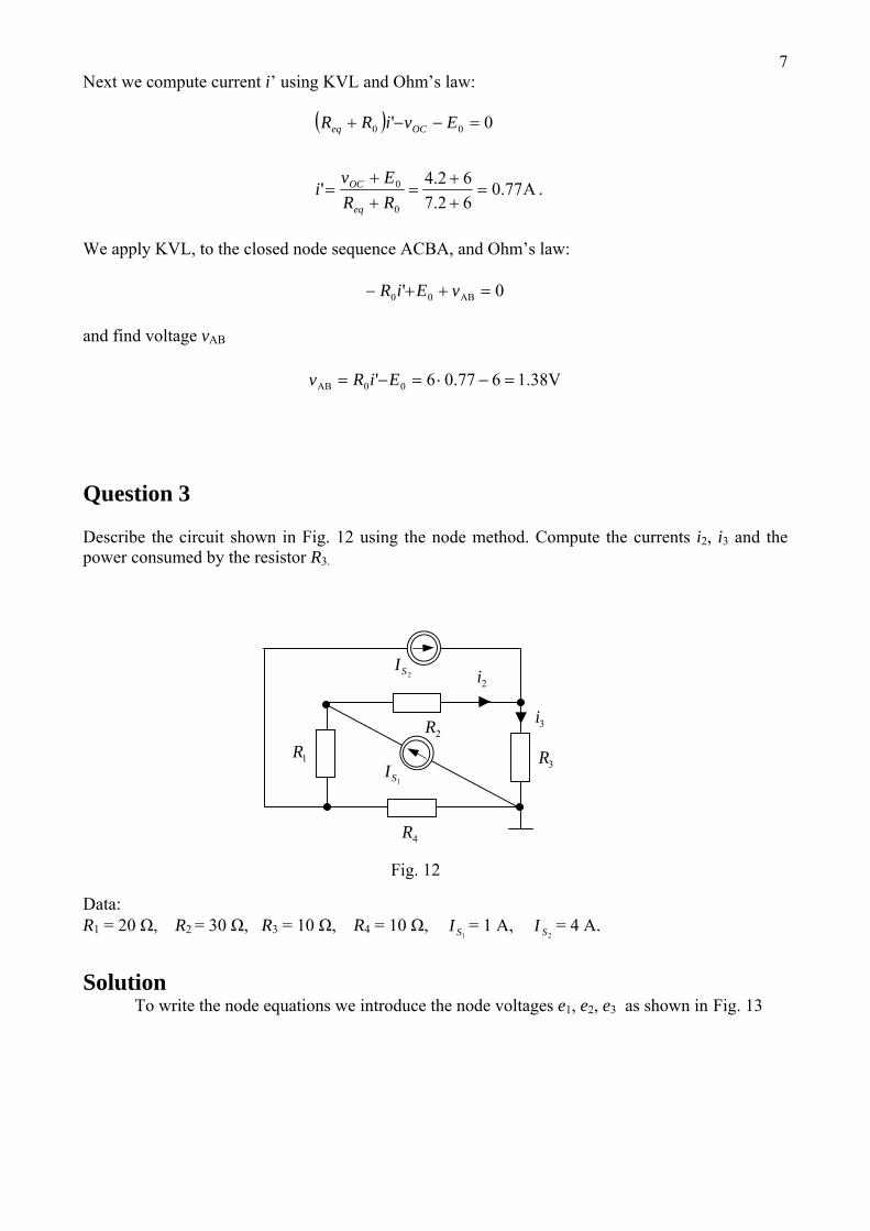
Question 3
Describe the circuit shown in Fig. 12 using the node method. Compute the currents i2, i3 and the power consumed by the resistor R3.
Ω, R2 = 30 Ω, R3 = 10 Ω, R4 = 10 Ω, = 1 A, = 4 A.
olution
2SI2i
3R2R
4R
1SI
3i
1R
Fig. 12
Data: R1 = 20
1SI2SI
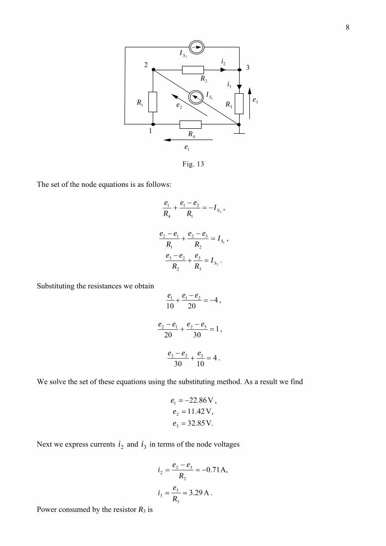
S To write the node equations we introduce the node voltages e1, e2, e3 as shown in Fig. 13
8
he set of the node equations is as follows:
1
2 3
3e
1e
2e
2SI2i
3R
2R
4R
1SI3i
1R
Fig. 13 T
21
21
4
1SI
Ree
Re
−=−
+ ,
12
32
1
12SI
Ree
Ree
=−− , +
23
3
2
23SI
Re
Ree
=+− .
Substituting the resistances we obtain
42010
211 −=−
+eee ,
13020
3212 =−−
+eeee ,
41030
323 =+− eee .
We solve the set of these equations using the substituting method. As a result we find
V86.221 −=e ,
.85.32,42.11
3
2
VV
==
ee
ext we express currents and in terms of the node voltages N 2i 3i
.29.3
,71.0
3
33
2
322
A
A
==
−=−
=
Re
i
Ree
i
Power consumed by the resistor R3 is
9.9.1072
333 W== iRP
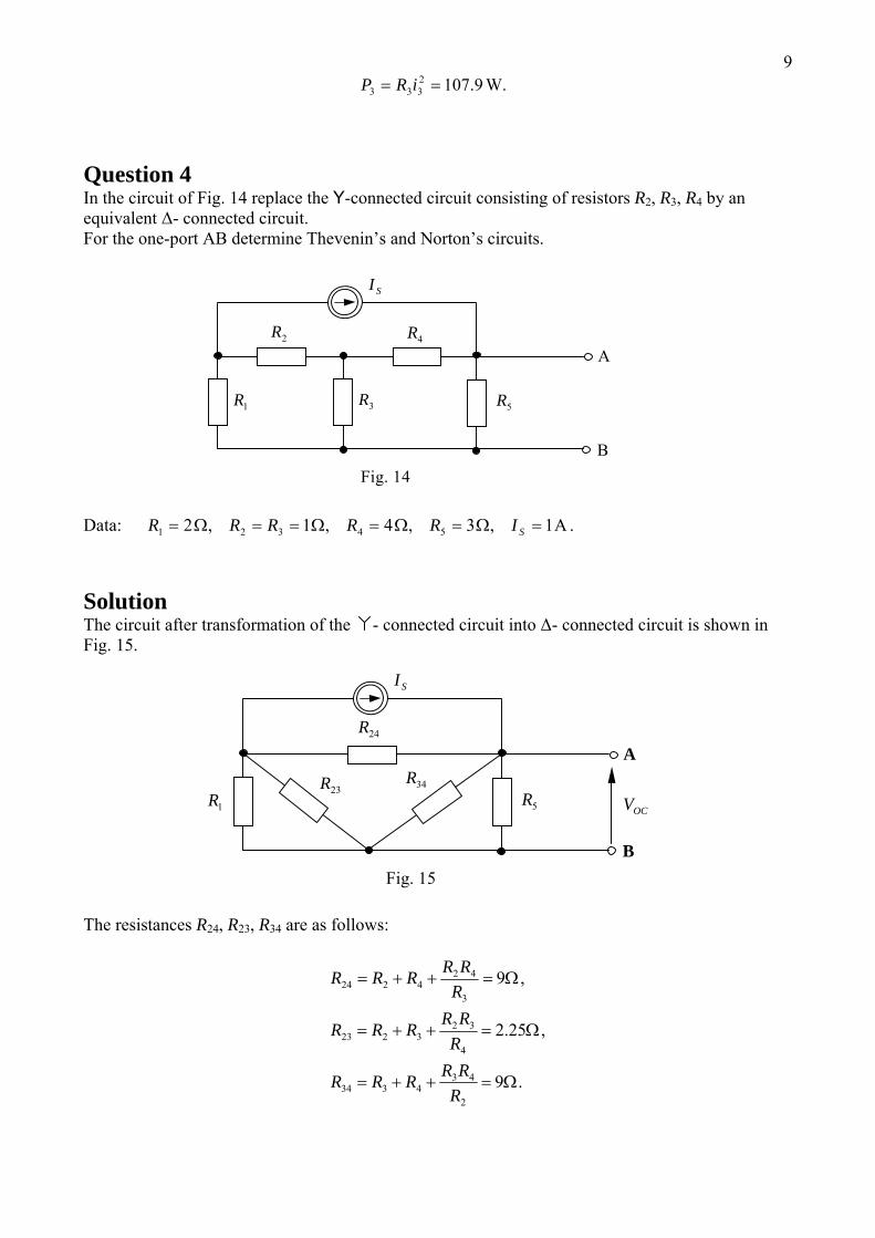
uestion 4 ig. 14 replace the Y-connected circuit consisting of resistors R2, R3, R4 by an
hevenin’s and Norton’s circuits.
ata:
QIn the circuit of Fequivalent Δ- connected circuit. For the one-port AB determine T
A
B
SI
3R
2R 4R
5R1R
Fig. 14
D A1,3,4,1,2 54321 =Ω=Ω=Ω==Ω= SIRRRRR . Solution
er transformation of the - connected circuit into Δ- connected circuit is shown in
he resistances R24, R23, R34 are as follows:
The circuit aftFig. 15.
OCV
A
B
SI
34R
24R
23R5R1R
Fig. 15
T
.9
,25.2
,9
2
434334
4
323223
3
424224
Ω=++=
Ω=++=
Ω=++=
RRRRRR
RRRRRR
RRRRRR
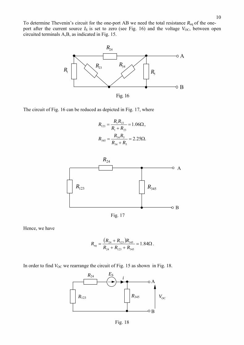
10To determine Thevenin’s circuit for the one-port AB we need the total resistance Req of the one-port after the current source IS is set to zero (see Fig. 16) and the voltage VOC, between open circuited terminals A,B, as indicated in Fig. 15.
A
B
34R
24R
23R5R1R
Fig. 16 The circuit of Fig. 16 can be reduced as depicted in Fig. 17, where
.25.2
,06.1
534
534345
231
231123
Ω=+
=
Ω=+
=
RRRRR
RRRRR
A
B
345R
24R
123R
Fig. 17 Hence, we have
( )Ω=
+++
= 84.134512324
34512324
RRRRRRReq .
In order to find VOC we rearrange the circuit of Fig. 15 as shown in Fig. 18.
OCV
ESi
R345
B
R24
A
R123
Fig. 18
11In this circuit the series connection of R24 and ES replaces the parallel connection of R24 and IS appeared in Fig. 15. Hence, it holds
V924 == RIE SS .
We compute the current i
A73.034512324
=++
=RRR
Ei S
and the voltage VOC
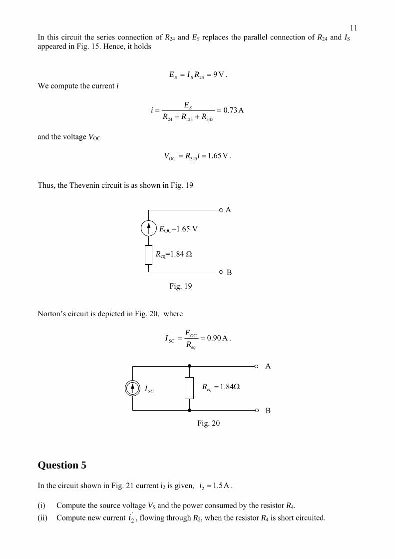
V65.1345 == iRVOC . Thus, the Thevenin circuit is as shown in Fig. 19
EOC=1.65 V
A
Req=1.84 Ω
B
Fig. 19 Norton’s circuit is depicted in Fig. 20, where
A90.0==eq
OCSC R
EI .
A
B
SCI
Ω= 84.1eqR
Fig. 20
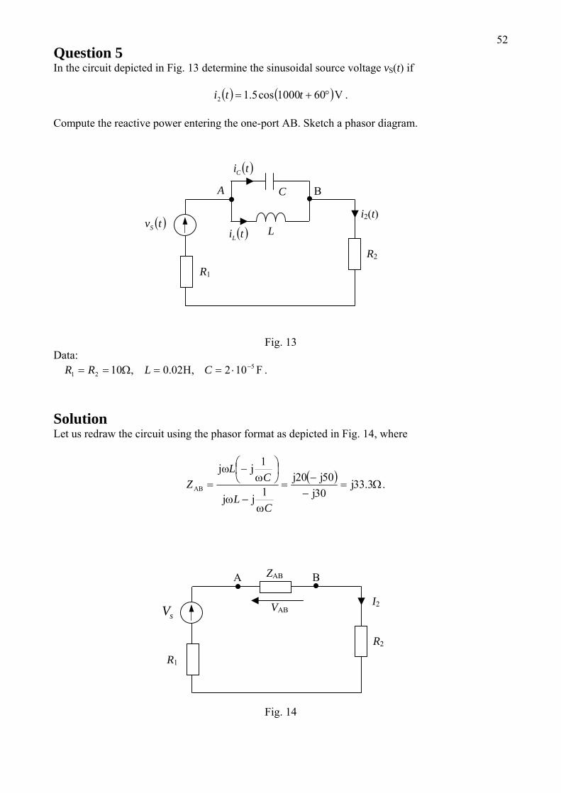
Question 5
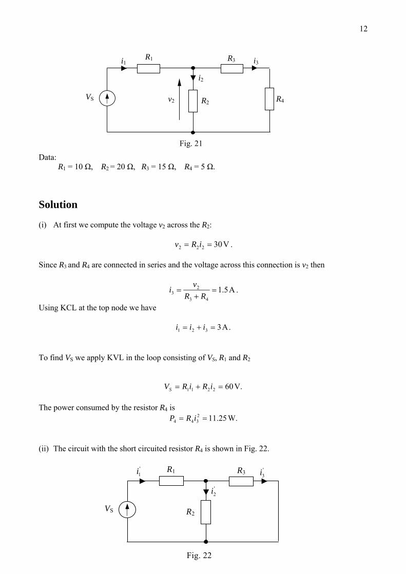
In the circuit shown in Fig. 21 current i2 is given, A5.12 =i . (i) Compute the source voltage VS and the power consumed by the resistor R4. (ii) Compute new current , flowing through R'
2i 2, when the resistor R4 is short circuited.
12
VS v2
i2
R3
R2 R4
i1 i3R1
Fig. 21
Data: R1 = 10 Ω, R2 = 20 Ω, R3 = 15 Ω, R4 = 5 Ω.
Solution (i) At first we compute the voltage v2 across the R2:
V30222 == iRv . Since R3 and R4 are connected in series and the voltage across this connection is v2 then
A5.143
23 =
+=
RRvi .
Using KCL at the top node we have
.A3321 =+= iii To find VS we apply KVL in the loop consisting of VS, R1 and R2
V.602211 =+= iRiRVS The power consumed by the resistor R4 is
W.25.112344 == iRP
(ii) The circuit with the short circuited resistor R4 is shown in Fig. 22. '
3i
'2i
'1i
VS
R3
R2
R1
Fig. 22
13In this circuit we find:
,A23.3
35152010
60
32
321
'1 =
⋅+
=
++
=
RRRR
R
Vi S
.38.1351523.3
32
3'1
'2 A==
+=
RRR
ii
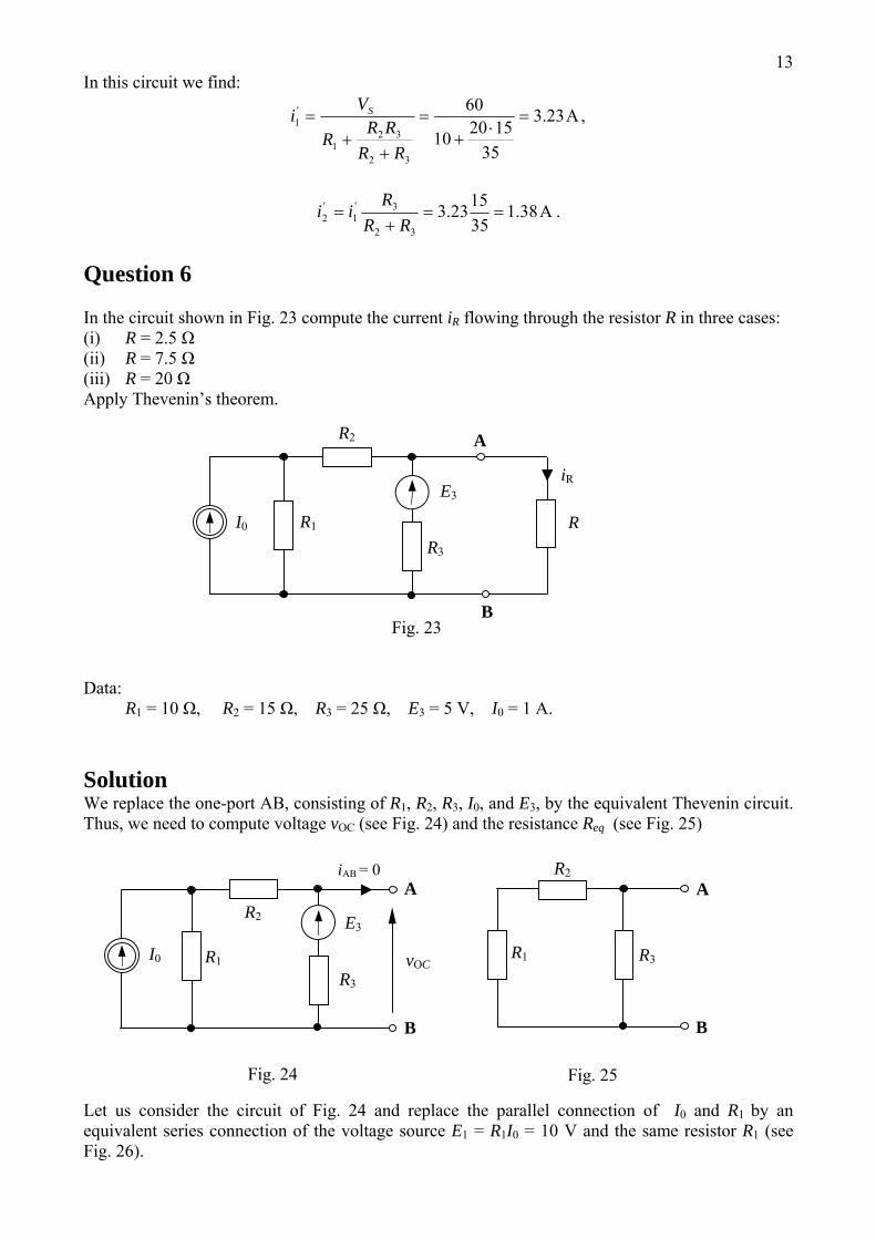
Question 6
In the circuit shown in Fig. 23 compute the current iR flowing through the resistor R in three cases: (i) R = 2.5 Ω (ii) R = 7.5 Ω (iii) R = 20 Ω Apply Thevenin’s theorem.
iR
B
A
E3
R3
R2
R I0 R1
Fig. 23
Data: R1 = 10 Ω, R2 = 15 Ω, R3 = 25 Ω, E3 = 5 V, I0 = 1 A. Solution We replace the one-port AB, consisting of R1, R2, R3, I0, and E3, by the equivalent Thevenin circuit. Thus, we need to compute voltage vOC (see Fig. 24) and the resistance Req (see Fig. 25)
R3
R2iAB = 0
E3
R1
R2
B
A
vOC
A
R3
I0
B
R1
Fig. 24 Fig. 25
Let us consider the circuit of Fig. 24 and replace the parallel connection of I0 and R1 by an equivalent series connection of the voltage source E1 = R1I0 = 10 V and the same resistor R1 (see Fig. 26).
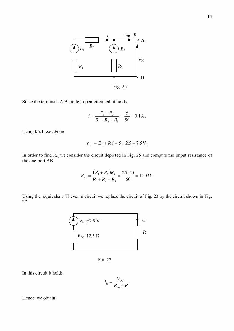
14
vOC
E1
i iAB= 0
B
A
R3
R2 E3
R1
Fig. 26
Since the terminals A,B are left open-circuited, it holds
.A1.0505
321
31 ==++
−=
RRREE
i
Using KVL we obtain
.V5.75.25330 =+=+= iREv C
In order to find Req we consider the circuit depicted in Fig. 25 and compute the imput resistance of the one-port AB
( ).5.12
502525
321
321 Ω=⋅
=++
+=
RRRRRR
Req
Using the equivalent Thevenin circuit we replace the circuit of Fig. 23 by the circuit shown in Fig. 27.
VOC=7.5 V
R
iR
Req=12.5 Ω
Fig. 27
In this circuit it holds
.RR
Vi
eq
OCR +=
Hence, we obtain:
15
(i) A5.05.25.12
5.7' =+
=Ri
(ii) A375.05.75.12
5.7'' =+
=Ri
(iii) A.230.0205.12
5.7''' =+
=Ri
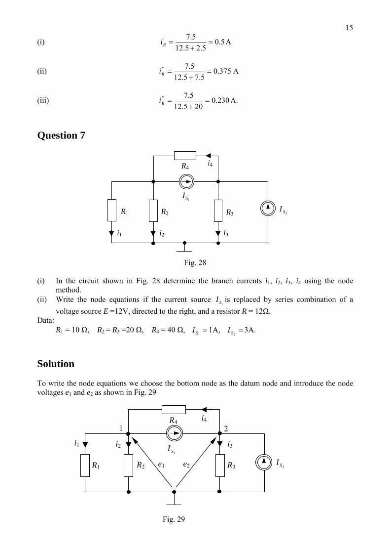
Question 7
2SI1SI
i4
i2
R3R2
R4
i1 i3
R1
Fig. 28
(i) In the circuit shown in Fig. 28 determine the branch currents i1, i2, i3, i4 using the node method.
(ii) Write the node equations if the current source is replaced by series combination of a voltage source E =12V, directed to the right, and a resistor R = 12Ω.
1SI
Data: R1 = 10 Ω, R2 = R3 =20 Ω, R4 = 40 Ω, =
1SI 1A, =2SI 3A.
Solution To write the node equations we choose the bottom node as the datum node and introduce the node voltages e1 and e2 as shown in Fig. 29
i4
i3 i2 i1 1SI
R4
e2 e1
2 1
2SIR3R2 R1
Fig. 29
16(i) The node equations have the form
1
4
21
2
1
1
1SI
Ree
Re
Re
−=−
++ ,
21
3
2
4
12SS II
Re
Ree
+=+− .
We substitute the resistance and source values and perform simple rearrangements. As a result we obtain the following set of equations in two unknown variables e1 and e2: -e2 = -407e1, -e1 + 3e2 = 160 . This set of equations is solved using the substituting method. As a result we obtain: e1 = 2V e2 = 54V. Using the node voltages we compute the branch currents as follows:
A2.01
11 ==
Rei , A1.0
2
12 ==
Rei , A7.2
3
23 ==
Rei , A3.1
4
124 =
−=
Reei .
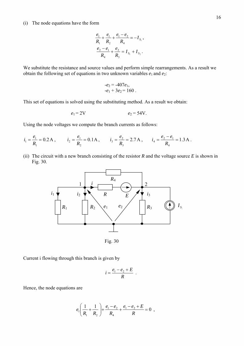
(ii) The circuit with a new branch consisting of the resistor R and the voltage source E is shown in
Fig. 30.
R E
i
i3 i2 i1
R4
e2 e1
2 1
2SIR3R2 R1
Fig. 30 Current i flowing through this branch is given by
R
Eeei +−= 21 .
Hence, the node equations are
011 21
4
21
211 =
+−+
−+⎟⎟
⎠
⎞⎜⎜⎝
⎛+
REee
Ree
RRe ,
17
2
3
212
4
12SI
Re
REee
Ree
=+−−
+− .
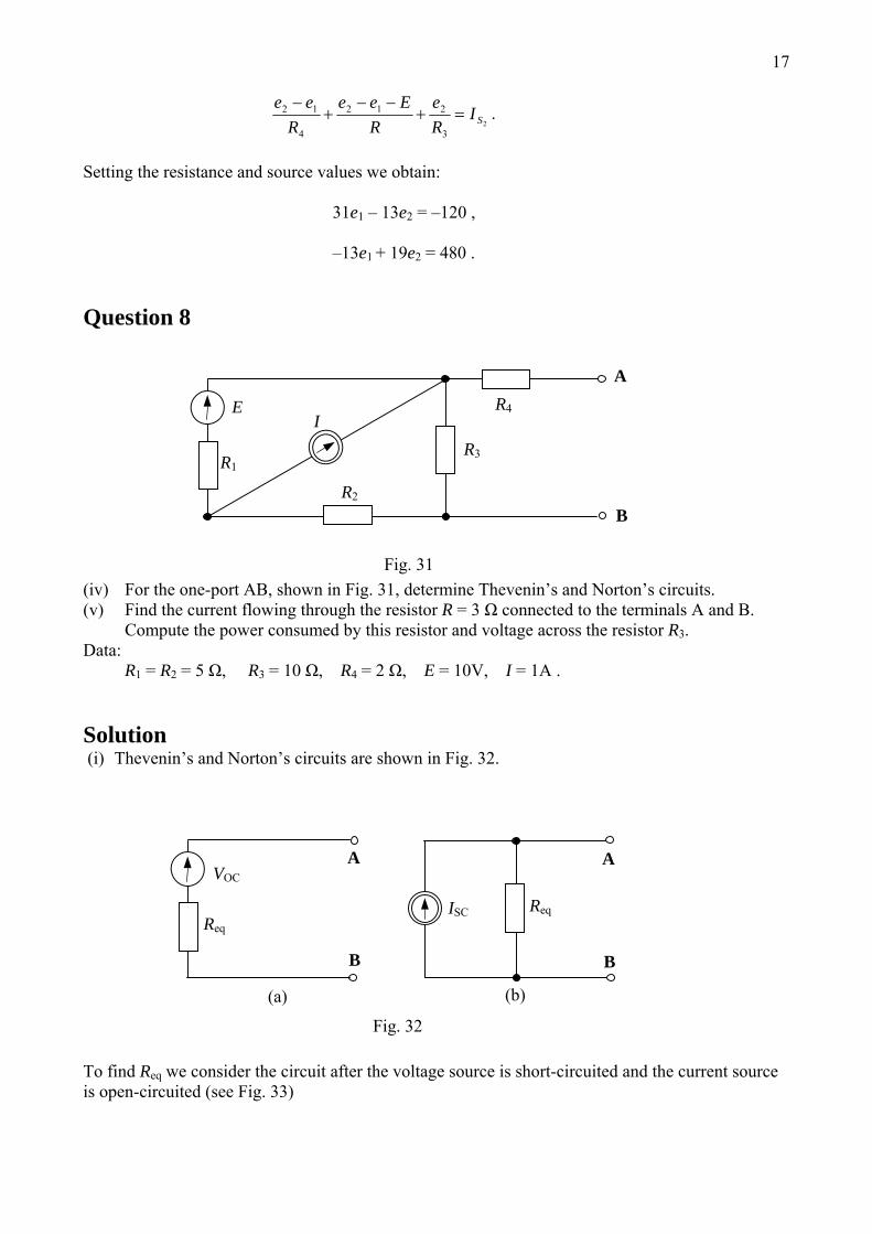
Setting the resistance and source values we obtain: 31e1 – 13e2 = –120 , –13e1 + 19e2 = 480 . Question 8
B
A
E
R3
R2
R4I
R1
Fig. 31(iv) For the one-port AB, shown in Fig. 31, determine Thevenin’s and Norton’s circuits. (v) Find the current flowing through the resistor R = 3 Ω connected to the terminals A and B.
Compute the power consumed by this resistor and voltage across the resistor R3. Data: R1 = R2 = 5 Ω, R3 = 10 Ω, R4 = 2 Ω, E = 10V, I = 1A . Solution (i) Thevenin’s and Norton’s circuits are shown in Fig. 32.
(b)(a)
B
A VOC
A
Req ISC
B
Req
Fig. 32 To find Req we consider the circuit after the voltage source is short-circuited and the current source is open-circuited (see Fig. 33)
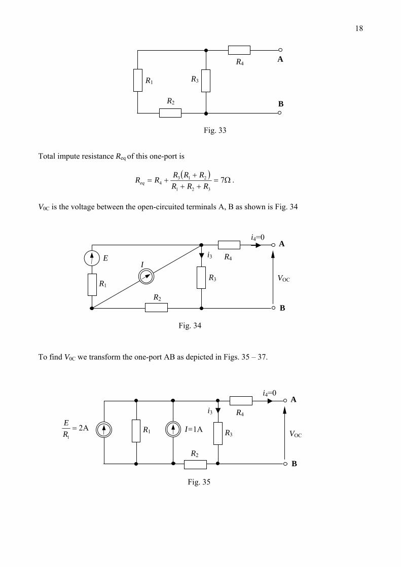
18
B
A
R3
R2
R4
R1
Fig. 33
Total impute resistance Req of this one-port is
( )Ω=
+++
+= 7321
2134 RRR
RRRRReq .
V0C is the voltage between the open-circuited terminals A, B as shown is Fig. 34
i3
VOC
i4=0
B
A
E
R3
R2
R4I
R1
Fig. 34 To find V0C we transform the one-port AB as depicted in Figs. 35 – 37.
i3
Fig. 35
VOC
i4=0
B
A
A21
=RE
R3
R2
R4
I=1AR1
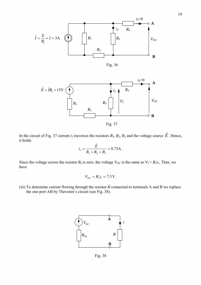
19
i3
Fig. 36
VOC
i4=0
B
A
A3ˆ1
=+= IREI R3
R2
R4
R1
V3 VOC
i4=0
B
A
V15ˆˆ1 == RIE
R3
R2
R4i3
R1
Fig. 37
In the circuit of Fig. 37 current i3 traverses the resistors R3, R2, R1 and the voltage source E . Hence, it holds
A75.0ˆ
3213 =
++=
RRREi .
Since the voltage across the resistor R4 is zero, the voltage VOC is the same as V3 = R3i3. Thus, we have
V.5.733 == iRVOC (iii) To determine current flowing through the resistor R connected to terminals A and B we replace
the one-port AB by Thevenin’s circuit (see Fig. 38).
B
AOCV
R
i
Req
Fig. 38
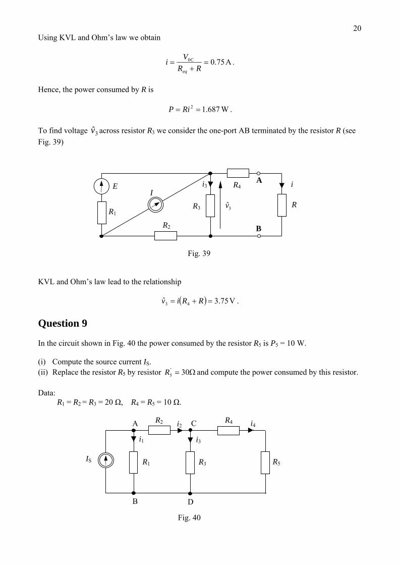
20Using KVL and Ohm’s law we obtain
A75.00 =+
=RR
Vi
eq
C .
Hence, the power consumed by R is
W687.12 == RiP . To find voltage across resistor R3v 3 we consider the one-port AB terminated by the resistor R (see Fig. 39)
VL and Ohm’s law lead to the relationship
i
R 3v
i3
B
AE
R3
R2
R4I
R1
Fig. 39 K
( ) V75.3ˆ 43 =+= RRiv .
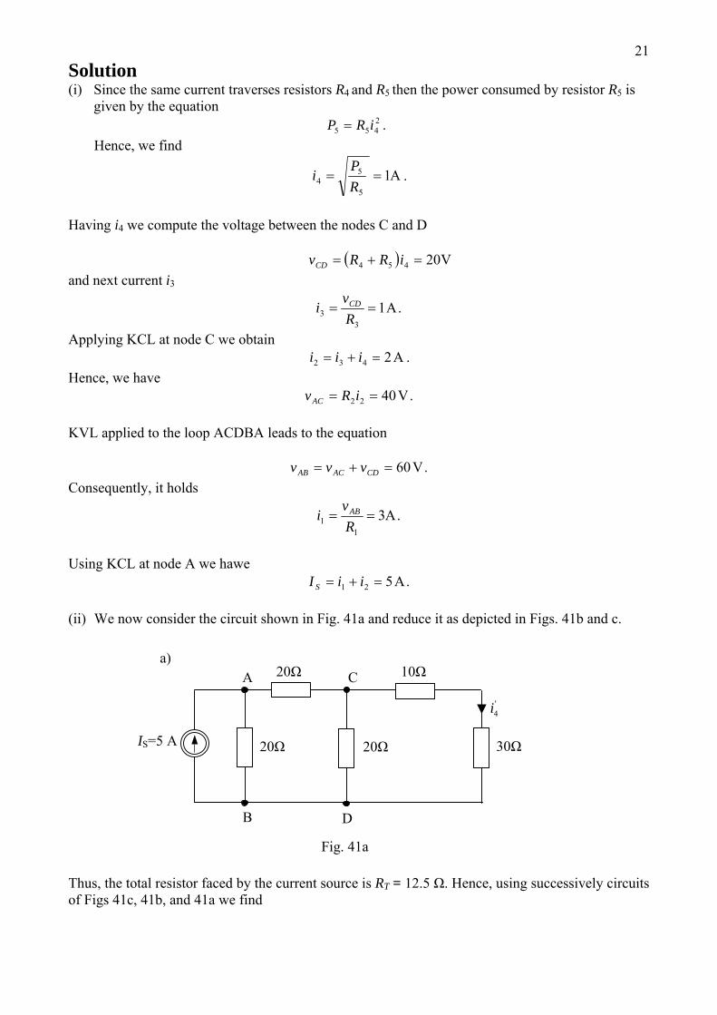
uestion 9
In the circuit shown in Fig. 40 the power consumed by the resistor R5 is P5 = 10 W.
the source current IS. or and compute the power consumed by this resistor.
ata: 1 = R2 = R3 = 20 Ω, R4 = R5 = 10 Ω.
Q
(i) Compute(ii) Replace the resistor R5 by resist Ω= 30'
5R D R
i4
D
C
B
A
IS R5
i2
R3
R2 R4
i1 i3
R1
Fig. 40
21Solution (i) Since the same current traverses resistors R4 and R5 then the power consumed by resistor R5 is
given by the equation . Hence, we find
2455 iRP =
A15
54 ==
RP
i .
Having i4 we compute the voltage between the nodes C and D
( ) V20454 =+= iRRvCD and next current i3
.A13
3 ==Rv
i CD
Applying KCL at node C we obtain A2432 =+= iii .
Hence, we have .V4022 == iRvAC
KVL applied to the loop ACDBA leads to the equation
.V60=+= CDACAB vvv Consequently, it holds
.A31
1 ==Rvi AB
Using KCL at node A we hawe
.A521 =+= iiI S
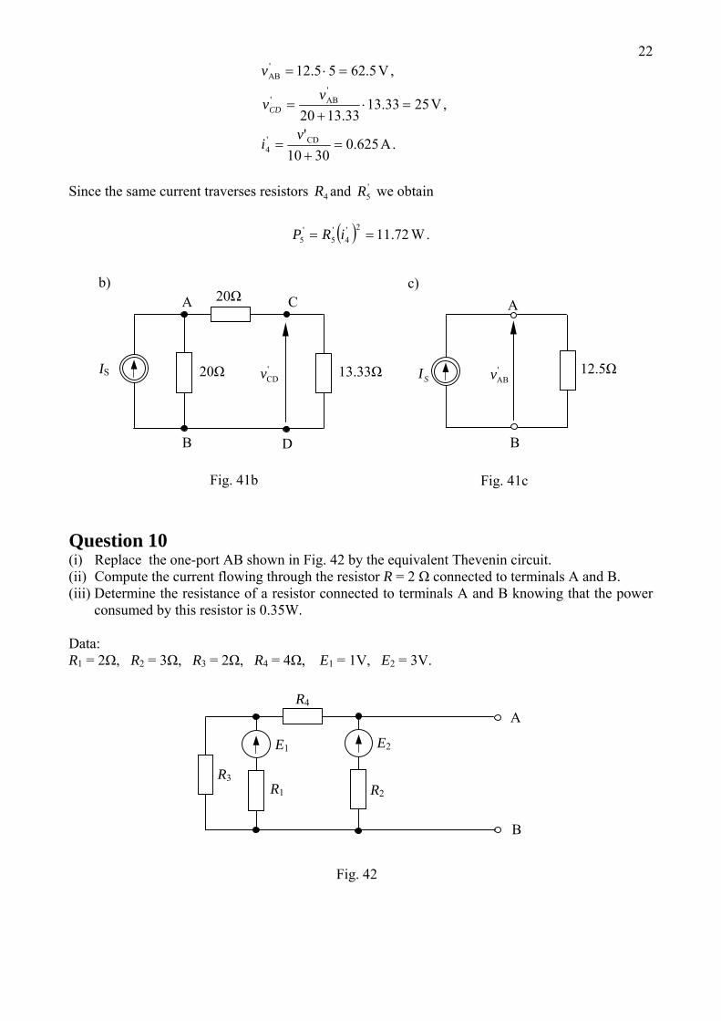
(ii) We now consider the circuit shown in Fig. 41a and reduce it as depicted in Figs. 41b and c.
'4i
D
C
B
A
IS=5 A 30Ω 20Ω
20Ω 10Ωa)
20Ω
Fig. 41a Thus, the total resistor faced by the current source is RT = 12.5 Ω. Hence, using successively circuits of Figs 41c, 41b, and 41a we find
22
.A3010
,V13.3320
,V
CD
'AB
'AB
625.0'
2533.13
5.6255.12
'4
'
=+
=
=⋅+
=
=⋅=
vi
vv
v
CD
Since the same current traverses resistors and we obtain 4R '
5R
( ) .W72.112'4
'5
'5 == iRP
'ABv
Fig. 41c
A
B
'CDv SI
D
C
B
A
IS 13.33Ω
20Ω
12.5Ω
b)
20Ω
Fig. 41b
c)
Question 10 (i) Replace the one-port AB shown in Fig. 42 by the equivalent Thevenin circuit. (ii) Compute the current flowing through the resistor R = 2 Ω connected to terminals A and B. (iii) Determine the resistance of a resistor connected to terminals A and B knowing that the power
consumed by this resistor is 0.35W.
Data: R1 = 2Ω, R2 = 3Ω, R3 = 2Ω, R4 = 4Ω, E1 = 1V, E2 = 3V.
E2E1
B
A R4
R1
R3 R2
Fig. 42
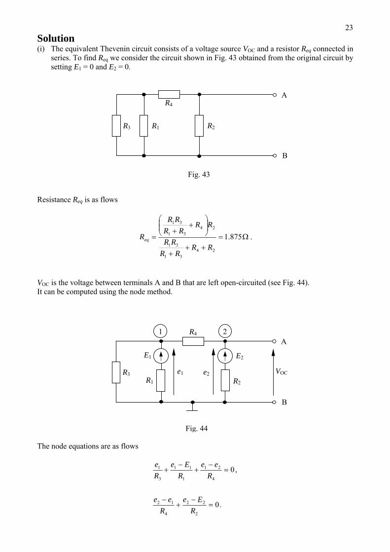
23Solution (i) The equivalent Thevenin circuit consists of a voltage source VOC and a resistor Req connected in
series. To find Req we consider the circuit shown in Fig. 43 obtained from the original circuit by setting E1 = 0 and E2 = 0.
B
A R4
R1 R3 R2
Fig. 43
Resistance Req is as flows
Ω=++
+
⎟⎟⎠
⎞⎜⎜⎝
⎛+
+= 875.1
2431
31
2431
31
RRRR
RR
RRRR
RR
Req .
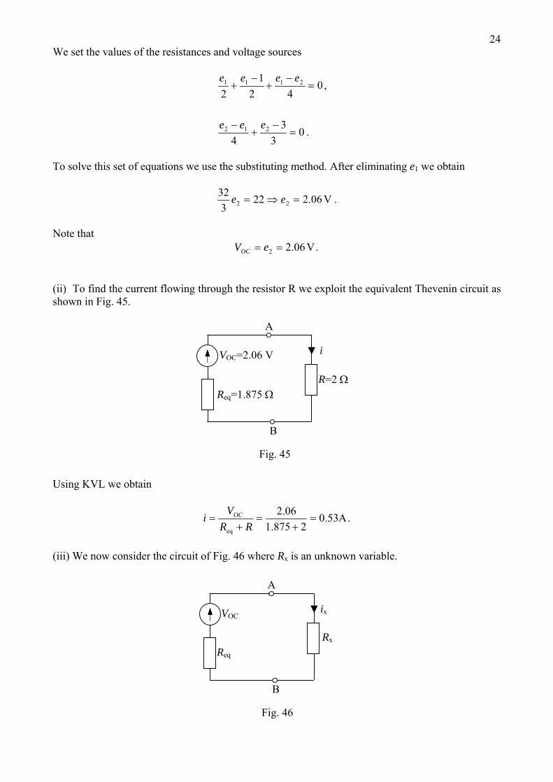
VOC is the voltage between terminals A and B that are left open-circuited (see Fig. 44). It can be computed using the node method.
VOC e2e1
E2E1
B
A R4
R1
R3 R2
Fig. 44
1 2
The node equations are as flows
.0
,0
2
22
4
12
4
21
1
11
3
1
=−
+−
=−
+−
+
REe
Ree
Ree
REe
Re
24We set the values of the resistances and voltage sources
.03
34
,042
12
212
2111
=−
+−
=−
+−
+
eee
eeee
To solve this set of equations we use the substituting method. After eliminating e1 we obtain
.V06.2223
3222 =⇒= ee
Note that
.V06.22 == eVOC (ii) To find the current flowing through the resistor R we exploit the equivalent Thevenin circuit as shown in Fig. 45.
iVOC=2.06 V
B
A
R=2 ΩReq=1.875 Ω
Fig. 45 Using KVL we obtain
.Aeq
OC 53.02875.1
06.2=
+=
+=
RRV
i
(iii) We now consider the circuit of Fig. 46 where Rx is an unknown variable.
ixVOC
B
A
Rx
Req
Fig. 46
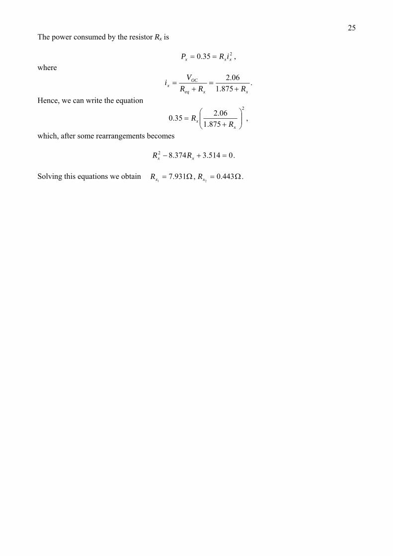
25The power consumed by the resistor Rx is
,35.0 2xxx iRP ==
where
.875.1
06.2
xxeq
OCx RRR
Vi
+=
+=
Hence, we can write the equation
,875.1
06.235.02
⎟⎟⎠
⎞⎜⎜⎝
⎛+
=x
x RR
which, after some rearrangements becomes
.0514.3374.82 =+− xx RR Solving this equations we obtain .443.0,931.7
21Ω=Ω= xx RR
27
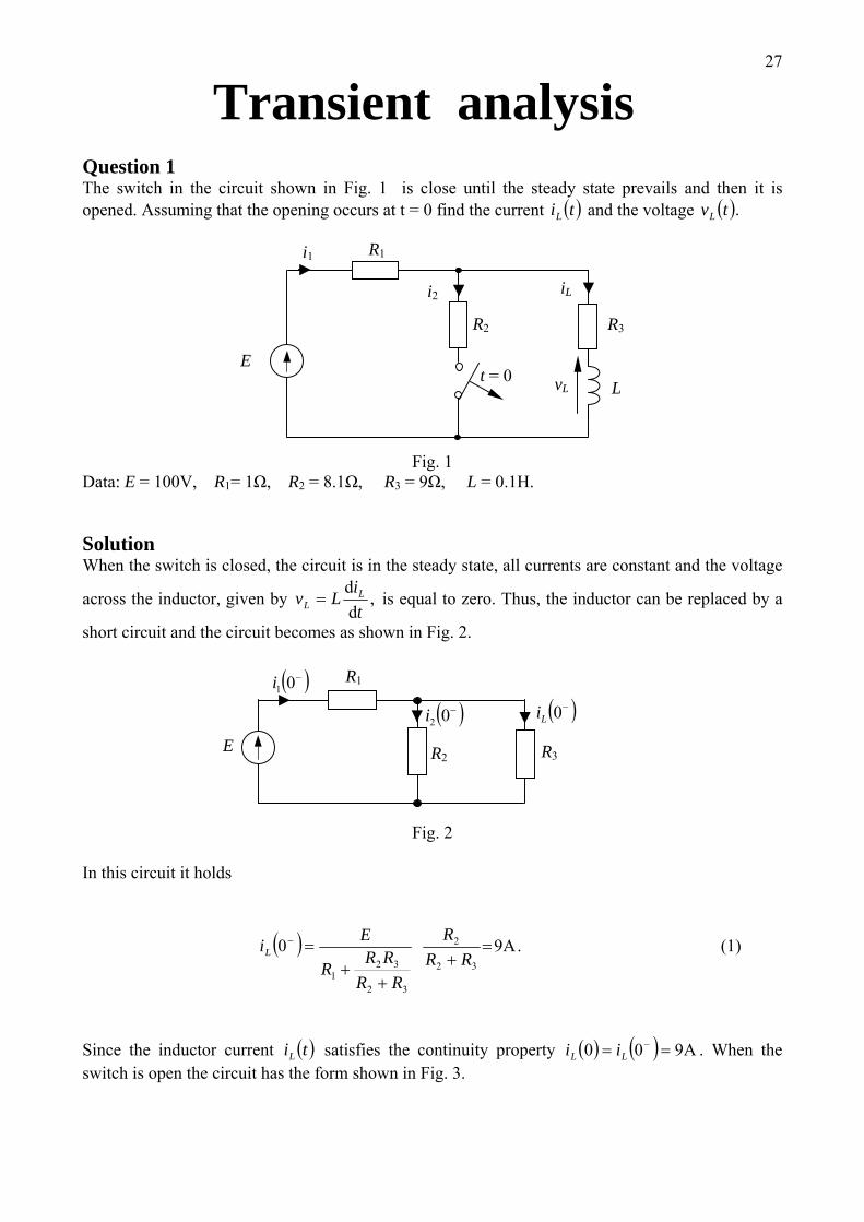
Transient analysis Question 1 The switch in the circuit shown in Fig. 1 is close until the steady state prevails and then it is opened. Assuming that the opening occurs at t = 0 find the current ( )tiL and the voltage ( ).tvL
i1
i2 iL
L t = 0
R2
E
R1
R3
vL
Fig. 1
Data: E = 100V, R1= 1Ω, R2 = 8.1Ω, R3 = 9Ω, L = 0.1H. Solution When the switch is closed, the circuit is in the steady state, all currents are constant and the voltage
across the inductor, given by ,tiLv L
L dd
= is equal to zero. Thus, the inductor can be replaced by a
short circuit and the circuit becomes as shown in Fig. 2.
( )−02i
E
( )−01i
R2
( )−0Li
R1
R3
Fig. 2
In this circuit it holds
( ) .A9032
2
32
321
=+
++
=−
RRR
RRRR
R
EiL (1)
Since the inductor current satisfies the continuity property ( )tiL ( ) ( ) A900 == −
LL ii . When the switch is open the circuit has the form shown in Fig. 3.
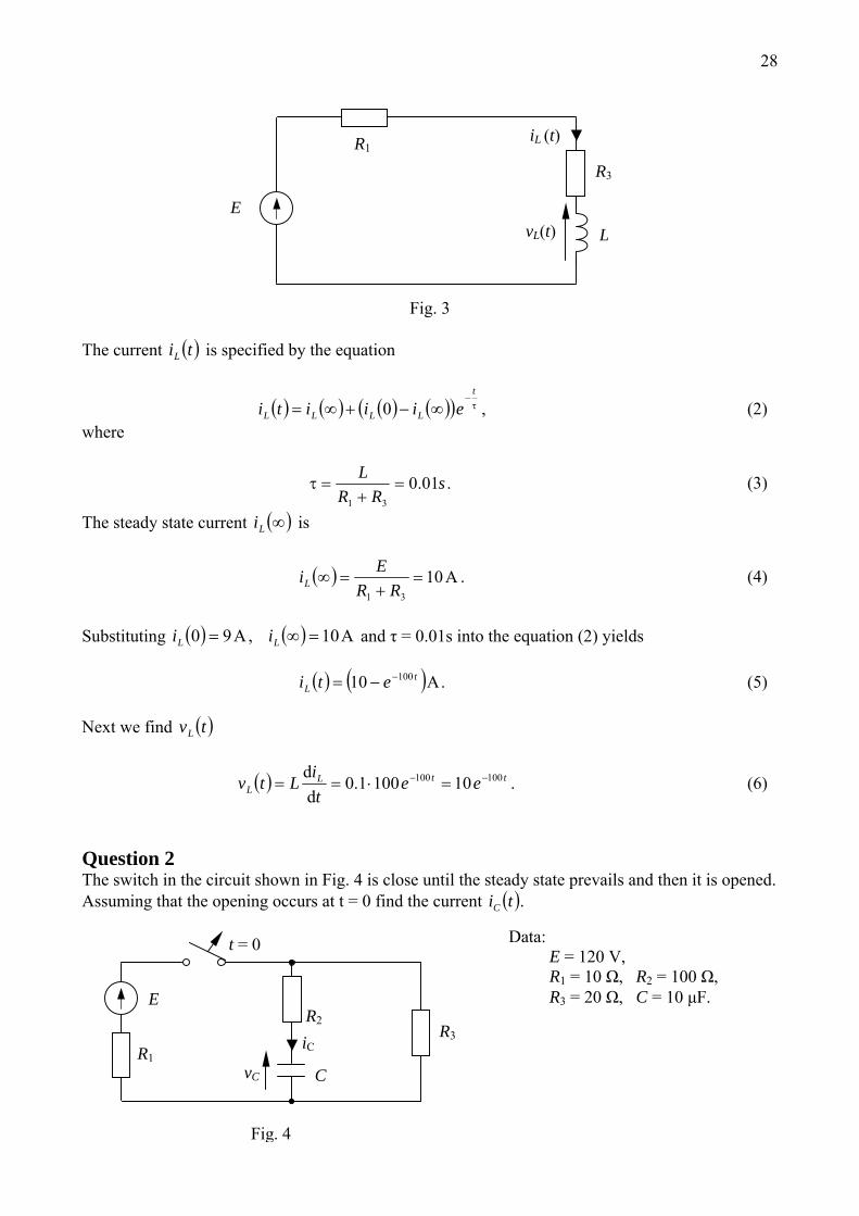
28
iL (t)
L E
R1
R3
vL(t)
Fig. 3
The current is specified by the equation ( )tiL
( ) ( ) ( ) ( )( ) ,0 τ−
∞−+∞=t
LLLL eiiiti (2) where
.01.031
sRR
L=
+=τ (3)
The steady state current is ( )∞Li
( ) A1031
=+
=∞RR
EiL . (4)
Substituting 0.01s into the equation (2) yields ( ) ( ) A,A 190 =∞= LL ii 0 and τ = ( ) ( ) .10 100 At
L eti −−= (5) Next we find v ( )tL
( ) .101001.0 100100 ttLL ee
tiLtv −− =⋅==
dd
(6)
Question 2 The switch in the circuit shown in Fig. 4 is close until the steady state prevails and then it is opened. Assuming that the opening occurs at t = 0 find the current ( ).tiC
iC
vC C
t = 0
R2
E
R1
R3
Data: E = 120 V, R1 = 10 Ω, R2 = 100 Ω, R3 = 20 Ω, C = 10 μF.
Fig. 4
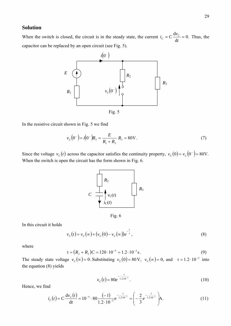
29 Solution
When the switch is closed, the circuit is in the steady state, the current .0==t
vCi C
C dd
Thus, the
capacitor can be replaced by an open circuit (see Fig. 5).
( )−0i
Fig. 5
R2 E
R1
R3
( )−0Cv
In the resistive circuit shown in Fig. 5 we find
( ) ( ) .V8000 331
3 =+
== −− RRR
ERivC (7)
Since the voltage across the capacitor satisfies the continuity property, ( )tvC ( ) ( ) V.8000 == −
CC vv When the switch is open the circuit has the form shown in Fig. 6.
iC(t) vC(t) C
R2
R3
Fig. 6
In this circuit it holds
( ) ( ) ( ) ( )( ) ,0 τ−
∞−+∞=t
CCCC evvvtv (8) where (9) ( ) .s35
32 102.110120 −− ⋅=⋅=+=τ CRRThe steady state voltage Substituting ( ) .0=∞Cv ( ) ( ) 3102.1,0800 −⋅=τ=∞= and V, CC vv into the equation (8) yields
( ) .80 3102.1 −⋅−
=t
C etv (10) Hence, we find
( ) ( ) ( ) .Ad
d⎟⎟⎠
⎞⎜⎜⎝
⎛−=
⋅−
⋅== −− ⋅−
⋅−
−− 33 102.1102.1
35
32
102.118010
ttC
C eet
tvCti (11)
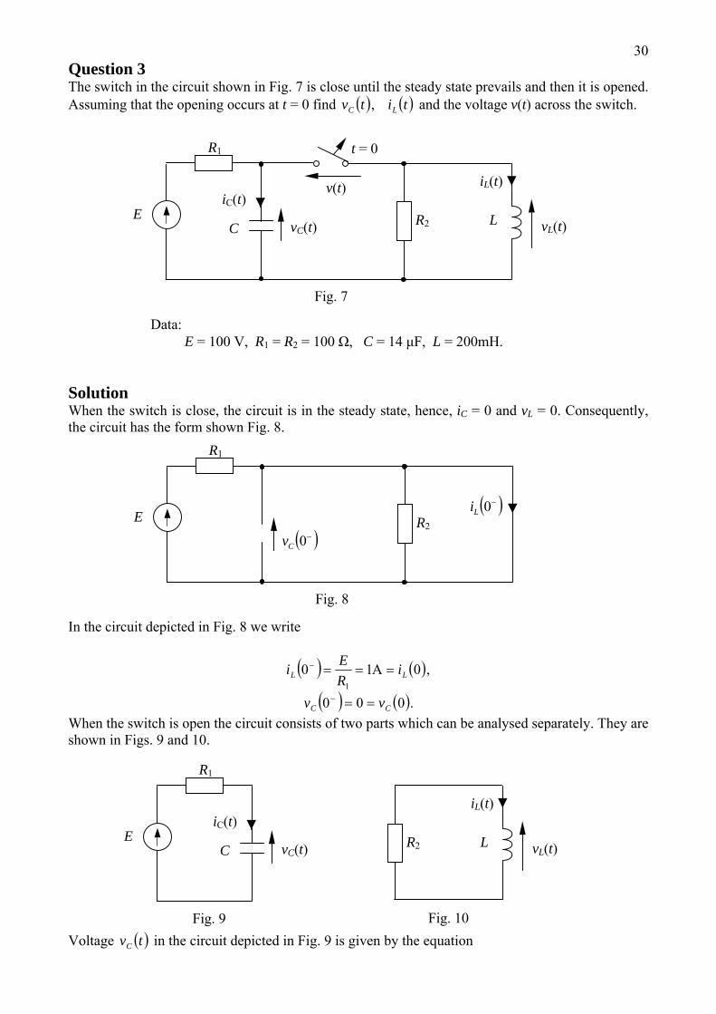
30Question 3 The switch in the circuit shown in Fig. 7 is close until the steady state prevails and then it is opened. Assuming that the opening occurs at t = 0 find ( ) ( )titv LC , and the voltage v(t) across the switch.
v(t)
vL(t)
iL(t)iC(t)
vC(t) C
t = 0
R2 E
R1
L
Data: E = 100 V, R1 = R2 = 100 Ω, C = 14 μF, L = 200mH.
Fig. 7
Solution When the switch is close, the circuit is in the steady state, hence, iC = 0 and vL = 0. Consequently, the circuit has the form shown Fig. 8.
( )−0Li
( )−0CvR2
E
R1
Fig. 8
In the circuit depicted in Fig. 8 we write
( ) ( ),0101
LL iREi ===− A
( ) ( ).000 CC vv ==− When the switch is open the circuit consists of two parts which can be analysed separately. They are shown in Figs. 9 and 10. Voltage in the circuit depicted in Fig. 9 is given by the equation ( )tvC
vL(t)
iL(t)iC(t)
vC(t) C
Fig. 10
R2 E
R1
L
Fig. 9
31
)
( ) ( ) ( ) ( )( ,0 1τ−
∞−+∞=t
CCCC evvvtv (12) where ,104.0 3
11 s−⋅==τ CR ( ) .V100==∞ EvC
Since we have ( ) ,00 =Cv
( ) .V⎟⎟⎠
⎞⎜⎜⎝
⎛−= −⋅
− 3104.01100t
C etv (13)
The circuit shown in Fig. 10 is described by the equation
( ) ( ) ( ) ( )( ) ,0 2τ−
∞−+∞=t
LLLL eiiiti (14) where
,s3
22 102 −⋅==τ
RL
( ) .0=∞Li Since then ( ) A10 =Li
( ) .A3102 −⋅−
=t
L eti (15) To find the voltage v(t), across the switch we apply KVL in the circuit shown in Fig. 7 ( ) ( ) ( )tvtvtv LC −= (16) where
( ) ( ) .10010212.0 33 102102
3 Vd
d −− ⋅−
⋅−
− −=⎟⎠⎞
⎜⎝⎛
⋅−==
ttL
L eettiLtv (17)
Substituting (13) and (17) into (16) yields
( ) .V⎟⎟⎠
⎞⎜⎜⎝
⎛+⎟⎟⎠
⎞⎜⎜⎝
⎛−= −− ⋅
−⋅
− 33 102104.0 1001100tt
eetv
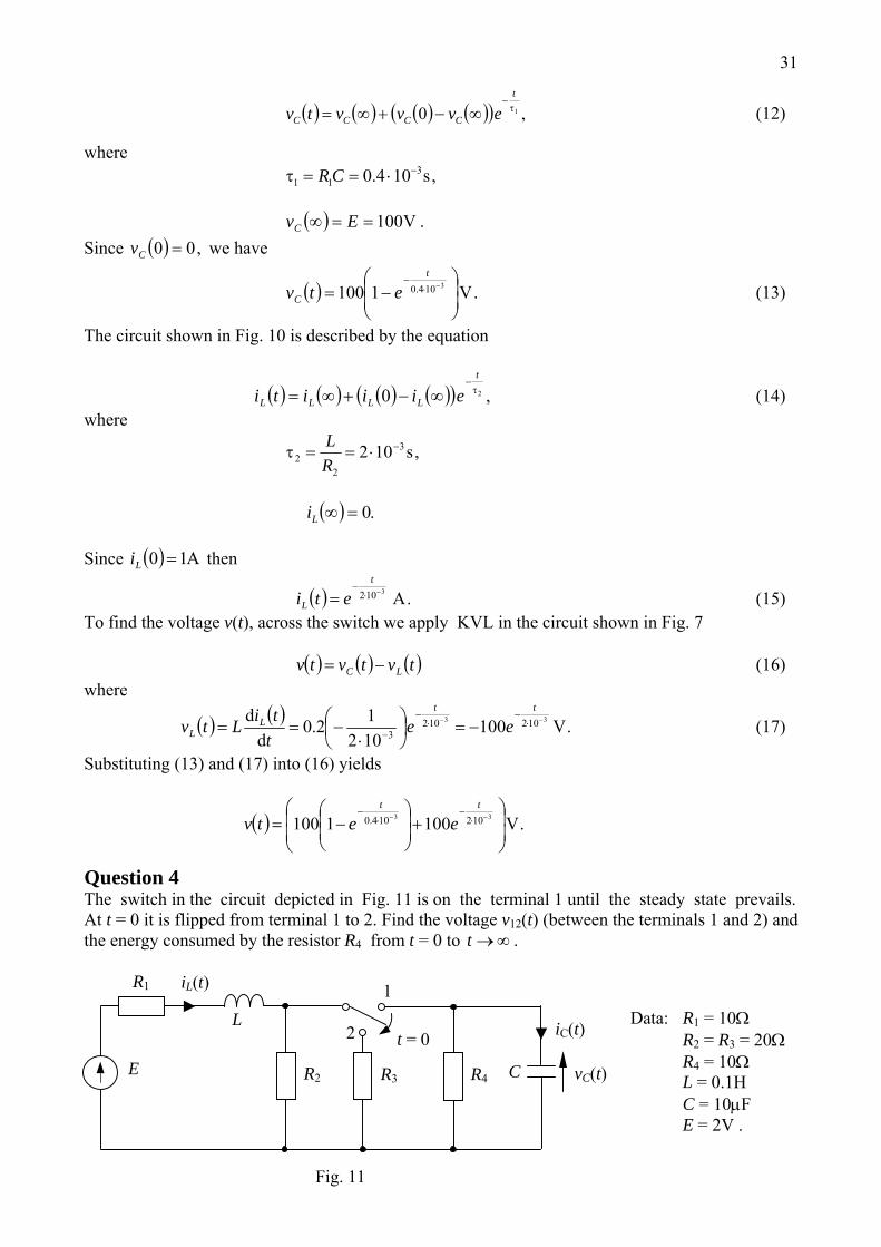
Question 4 The switch in the circuit depicted in Fig. 11 is on the terminal 1 until the steady state prevails. At t = 0 it is flipped from terminal 1 to 2. Find the voltage v12(t) (between the terminals 1 and 2) and the energy consumed by the resistor R4 from t = 0 to ∞→t .
2
1
R3 R4
iL(t)
iC(t)
vC(t) C
t = 0
R2 E
R1
L
Fig. 11
Data: R1 = 10Ω R2 = R3 = 20Ω R4 = 10Ω L = 0.1H C = 10μF E = 2V .
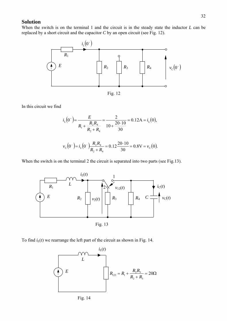
32Solution When the switch is on the terminal 1 and the circuit is in the steady state the inductor L can be replaced by a short circuit and the capacitor C by an open circuit (see Fig. 12).
R3 R4
( )−0Li
( )−0Cv R2 E
R1
Fig. 12
In this circuit we find
( ) ( )
( ) ( ) ( ).08.030
102012.000
,012.0
30102010
20
42
42
42
421
CLC
LL
vRR
RRiv
i
RRRRR
Ei
==⋅
=+
=
==⋅
+=
++
=
−−
−
V
A
When the switch is on the terminal 2 the circuit is separated into two parts (see Fig.13).
v2(t)
2
1
R3 R4
iL(t)
iC(t)
vC(t) C
v12(t)
R2 E
R1 L
Fig. 13
To find iL(t) we rearrange the left part of the circuit as shown in Fig. 14.
iL(t)
Ω=+
+= 2032
321123 RR
RRRRE
L
Fig. 14
33In this circuit
( ) ( ) ( ) ( )( ) ,0 1τ−
∞−+∞=t
LLLL eiiiti (18) where
( ) .A,s 1.0202005.0
201.0
1231231 ===∞===τ
REi
RL
L
Since then ( ) ,12.00 =Li
( ) .02.01.0 005.0 A⎟⎟⎠
⎞⎜⎜⎝
⎛+=
−t
L eti (19)
To find vC(t) we consider the right part of the circuit, consisting of the resistor R4 and the capacitor C connected in parallel. We write
( ) ( ) ( ) ( )( ) ,0 2τ−
∞−+∞=t
CCCC evvvtv (20) where ( ) .0101010 45
42 =∞=⋅==τ −−CvCR s,
Hence, we have
( ) .V⎟⎟⎠
⎞⎜⎜⎝
⎛= −
− 4108.0t
C etv (21)
In order to find v12(t) we apply KVL ( ) ( ) ( ),212 tvtvtv C−= (22) where
( ) ( ) .V⎟⎟⎠
⎞⎜⎜⎝
⎛+=
+=
−005.0
32
322 2.01
t
L eRR
RRtitv (23)
Substituting (21) and (23) into (22) gives
( ) .V⎟⎟⎠
⎞⎜⎜⎝
⎛−+= −
−− 410005.012 8.02.01
tt
eetv
The energy consumed by the resistor R4 is specified by the equation
( ) .
210064.064.01.0
0
1024
102
0 4
2
444
∫∫∞ ∞−−−∞
⋅=⎟⎟⎠
⎞⎜⎜⎝
⎛−=== −− J103.2dd 6-
0
ttC etetR
tvW
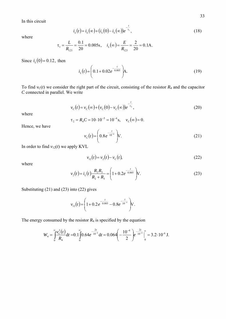
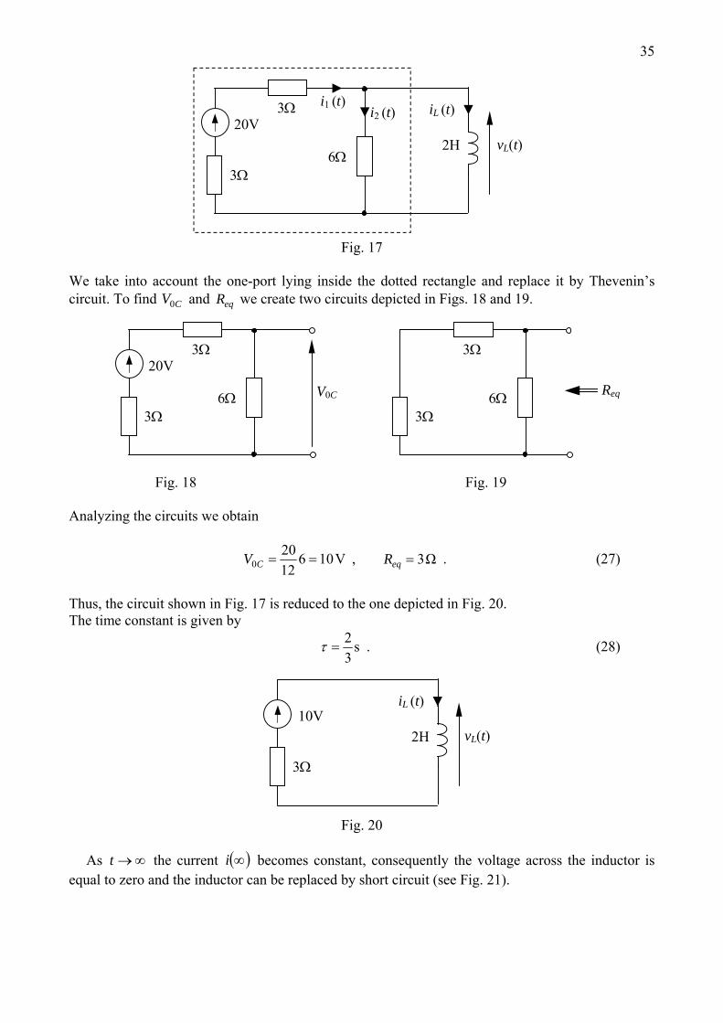
34Question 5
6 Ω
i2 (t)iL (t)
i1 (t)
t = 0
20 V
B
A
2 Ω
3 Ω
10 V
3 Ω
2 HvL (t)
Fig. 15 For the switch is on terminal A and the circuit is in steady state. At 0<t 0=t the switch is flipped to terminal B. Determine , and ( )tiL ( )ti1 ( )tvL for . 0≥t Solution For the current is constant, hence, it holds 0<t ( )tiL
( ) ( ) 0d
d==
ttiLtv L
L . (24)
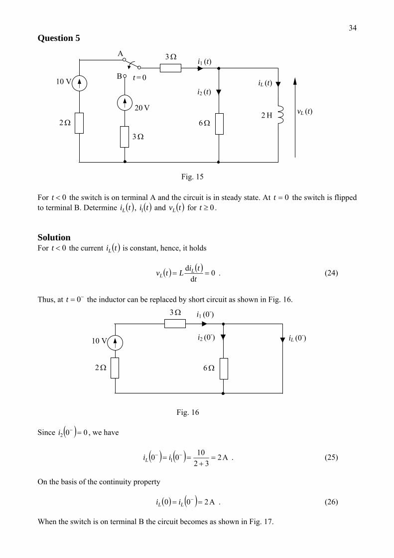
Thus, at the inductor can be replaced by short circuit as shown in Fig. 16. −= 0t
i1 (0-)
i2 (0-) iL (0-)
6 Ω2 Ω
10 V
3 Ω
Fig. 16 Since ( ) 002 =−i , we have
( ) ( ) A232
1000 1 =+
== −− iiL . (25)
On the basis of the continuity property ( ) ( ) A200 == −
LL ii . (26) When the switch is on terminal B the circuit becomes as shown in Fig. 17.
35
2H
iL (t)20V
3Ω
vL(t)
3Ω
6Ω
i1 (t) i2 (t)
Fig. 17
We take into account the one-port lying inside the dotted rectangle and replace it by Thevenin’s circuit. To find and we create two circuits depicted in Figs. 18 and 19. CV0 eqR
20V
3Ω
V0C
3Ω
6Ω
3Ω
Req
3Ω
6Ω
Fig. 18 Fig. 19 Analyzing the circuits we obtain
V1061220
0 ==CV , Ω3=eqR . (27)
Thus, the circuit shown in Fig. 17 is reduced to the one depicted in Fig. 20. The time constant is given by
s32
=τ . (28)
2H
iL (t)10V
3Ω
vL(t)
Fig. 20
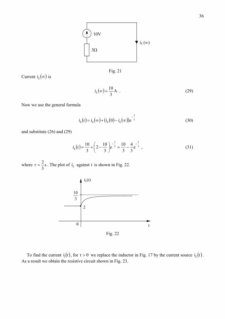
As the current becomes constant, consequently the voltage across the inductor is
equal to zero and the inductor can be replaced by short circuit (see Fig. 21). ∞→t ( )∞i
36
iL (∞)
10V
3Ω
Fig. 21
Current is ( )∞Li
( ) A3
10=∞Li . (29)
Now we use the general formula
( ) ( ) ( ) ( )( ) τt
LLLL iiiti−
∞−+∞= e0 (30) and substitute (26) and (29)
( ) ττtt
L ti−−
−=⎟⎠⎞
⎜⎝⎛ −+= e
34
310e
3102
310 , (31)
where s32
=τ . The plot of against t is shown in Fig. 22. Li
2
310
0 t
iL(t)
Fig. 22
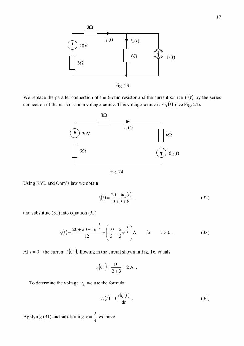
To find the current , for we replace the inductor in Fig. 17 by the current source ( )ti1 0>t ( )tiL . As a result we obtain the resistive circuit shown in Fig. 23.
37
i2 (t)i1 (t)
iL(t) 6Ω
3Ω
20V
3Ω
Fig. 23
We replace the parallel connection of the 6-ohm resistor and the current source by the series connection of the resistor and a voltage source. This voltage source is
( )tiL
( )tiL6 (see Fig. 24).
i1 (t)
6iL(t)
6Ω
3Ω
20V
3Ω
Fig. 24 Using KVL and Ohm’s law we obtain
( ) ( )633
6201 ++
+=
titi L , (32)
and substitute (31) into equation (32)
( ) 0forAe32
310
12e82020
1 >⎟⎟
⎠
⎞
⎜⎜
⎝
⎛−=
−+=
−−
ttit
t
ττ
. (33)
At the current −= 0t ( )−01i , flowing in the circuit shown in Fig. 16, equals
( ) A232
1001 =+
=−i .
To determine the voltage we use the formula Lv
( ) ( )ttiLtv L
L dd
= . (34)
Applying (31) and substituting 32
=τ we have
38
( ) τττ
tt
L tv−−
=⎟⎟
⎠
⎞
⎜⎜
⎝
⎛= e4e1
342 . (35)
For the circuit is in steady state and 0<t 0=Lv . The plot of against t shows that at the voltage jumps from 0 to 4 (see Fig. 25).
Lv 0=t
Lv
0
4
vL (t)
t
Fig. 25 Alternatively, the voltage , for can be found applying KVL in the circuit depicted in Fig. 17
( )tv1 0>t
( ) ( ) ( ) 02033 1 =−++ titvL (36) and substituting (33). As a result we obtain
( ) 0e4e32
310620 >=
⎟⎟
⎠
⎞
⎜⎜
⎝
⎛−−=
−−t,tv
tt
Lττ . (37)
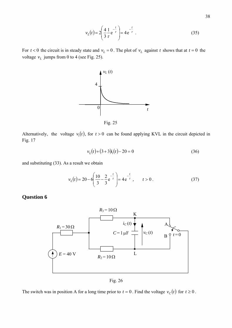
Question 6
iC (t)
t = 0
K
L
B
A
R2 = 10 Ω
R1 = 30 Ω
E = 40 V
R3 = 10 Ω
C = 1 μF vC (t)
Fig. 26
The switch was in position A for a long time prior to 0=t . Find the voltage for . ( )tvC 0≥t
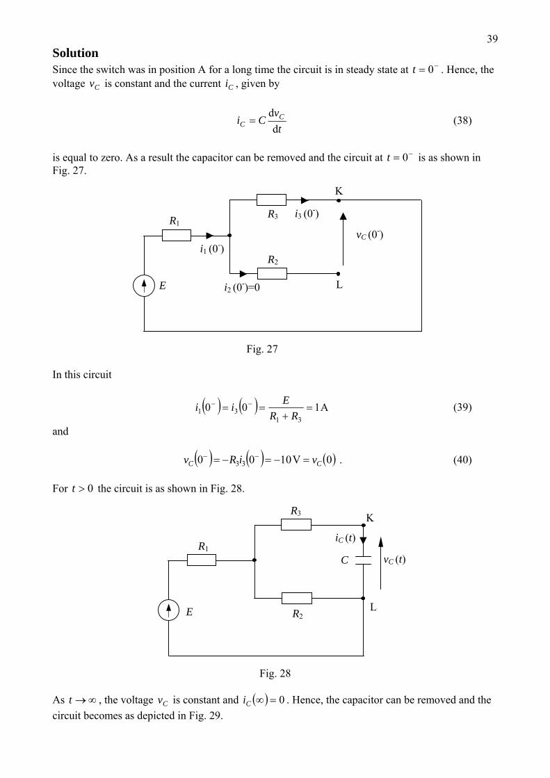
39Solution Since the switch was in position A for a long time the circuit is in steady state at . Hence, the voltage is constant and the current , given by
−= 0tCv Ci
t
vCi C
C dd
= (38)
is equal to zero. As a result the capacitor can be removed and the circuit at is as shown in Fig. 27.
−= 0t
i1 (0-)
i2 (0-)=0
i3 (0-)
K
L
R2
R1
E
R3
vC (0-)
Fig. 27 In this circuit
( ) ( ) A10031
31 =+
== −−
RREii (39)
and ( ) ( ) ( )0V1000 33 CC viRv =−=−= −− . (40) For the circuit is as shown in Fig. 28. 0>t
iC (t)
K
L R2
R1
E
R3
C vC (t)
Fig. 28
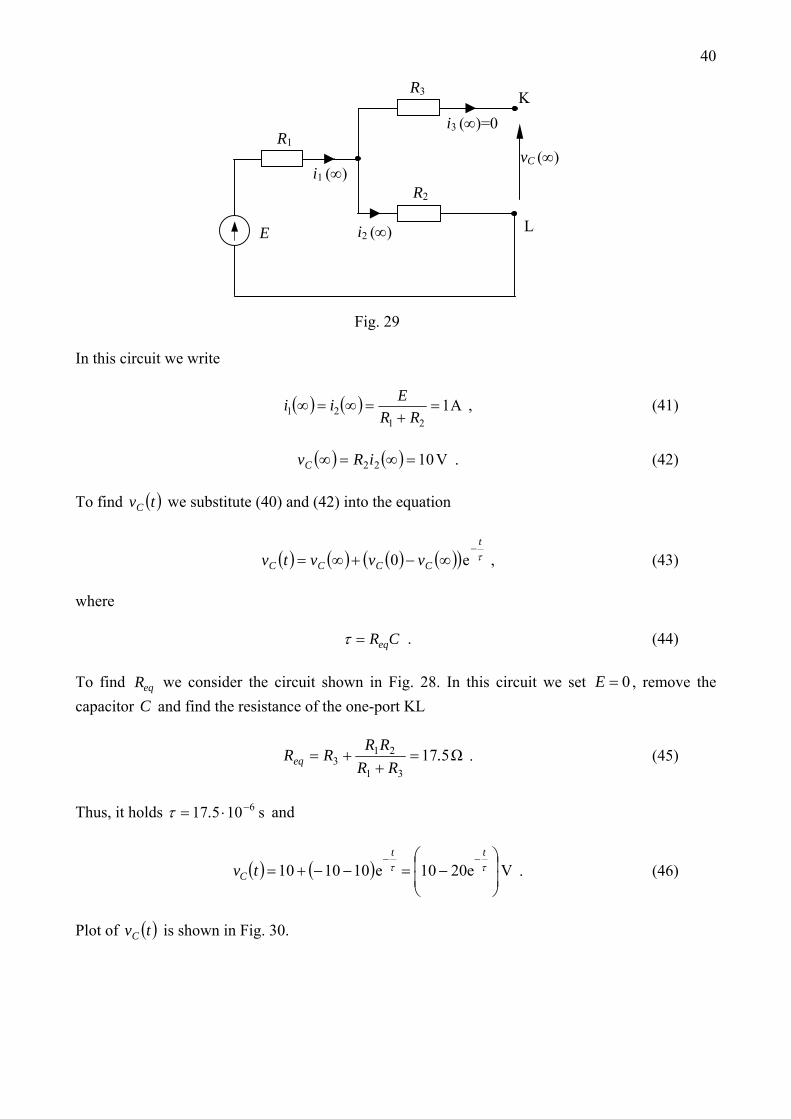
As , the voltage is constant and ∞→t Cv ( ) 0=∞Ci . Hence, the capacitor can be removed and the circuit becomes as depicted in Fig. 29.
40
i1 (∞)
i2 (∞)
i3 (∞)=0 K
L
R2
R1
E
R3
vC (∞)
Fig. 29 In this circuit we write
( ) ( ) A121
21 =+
=∞=∞RR
Eii , (41)
( ) ( ) V1022 =∞=∞ iRvC . (42) To find we substitute (40) and (42) into the equation ( )tvC
( ) ( ) ( ) ( )( ) τt
CCCC vvvtv−
∞−+∞= e0 , (43) where CReq=τ . (44) To find we consider the circuit shown in Fig. 28. In this circuit we set , remove the capacitor and find the resistance of the one-port KL
eqR 0=EC
Ω51731
213 .
RRRRRReq =+
+= . (45)
Thus, it holds and s10517 6−⋅= .τ
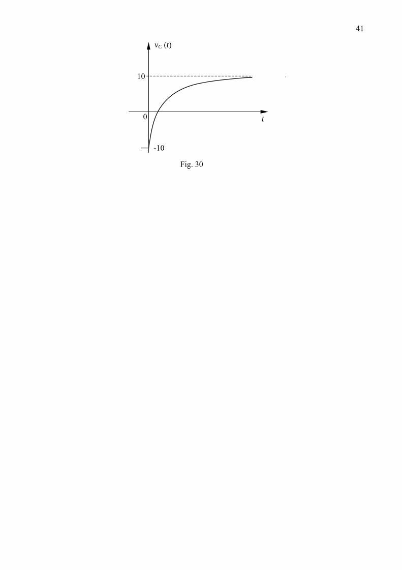
( ) ( ) Ve2010e101010⎟⎟
⎠
⎞
⎜⎜
⎝
⎛−=−−+=
−−ττtt
C tv . (46)
Plot of is shown in Fig. 30. ( )tvC
41
-10
0
10
t
vC (t)
Fig. 30
43
AC analysis Question 1
v2(t)
i3(t)
vC(t)
vL(t)
i2(t)
i1(t)
vs(t)
C
L
R1R2
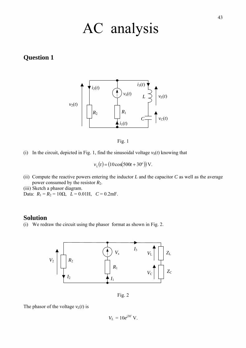
Fig. 1 (i) In the circuit, depicted in Fig. 1, find the sinusoidal voltage vS(t) knowing that
( ) ( )( ) .30500cos10 V°+= ttvL
(ii) Compute the reactive powers entering the inductor L and the capacitor C as well as the average power consumed by the resistor R2.
(iii) Sketch a phasor diagram. Data: R1 = R2 = 10Ω, L = 0.01H, C = 0.2mF. Solution (i) We redraw the circuit using the phasor format as shown in Fig. 2.
V2
VCI2
I3Vs
R2
ZCR1
ZLVL
I1
Fig. 2
The phasor of the voltage vL(t) is
VL = 10ej30˚ V.
44To determine the voltage source we proceed as follows. At first we compute the current I3
L
L
ZVI =3 ,
where ZL = jωL = j5Ω = 5ej90˚ Ω.
Hence, it holds
Ajjj
j
)732.11()60sin60(cos225
10 6090
30
3 −=°−°=== °−°
°
eeeI .
Then we compute the voltage V2
V2 = VL + VC = I3(ZL + ZC),
where
Ω=Ω−=−= °− 9010101 jjω
j eC
ZC .
According to the foregoing
V2 = 2e-j60˚ (j5-j10) = 10e-j150˚ = 10 (cos 150˚ - j sin 150˚) = (-8.66 – j5)V.
Using Ohm’s law we find the current I2
.)5.0866.0(150
2
22 Ajj −−=== °−e
RVI
KCL applied to the bottom node leads to the equation
–I2 + I1 – I3 = 0 or
I1 = I2 + I3 = (0.134 – j2.232) A .
The results obtained above enable us to determine the source voltage
VS = V2 + R1I1 = (-7.32 – j27.32) V = 28.28ej255˚ V.
Now we go from the phasor VS to the time varying voltage vS(t)
vS(t) = Re(VSejωt) = 28.28cos(500t + 255˚) = 28.28cos(500t - 105˚) V. (ii) The reactive powers entering the inductor L and the capacitor C are as follows:
VAR1021 2
3 == LX XIPL
,
45VAR20
21 2
3 −== CX XIPC
,
whereas the average power consumed by the resistor R2 is
.521 2
222W== IRPav
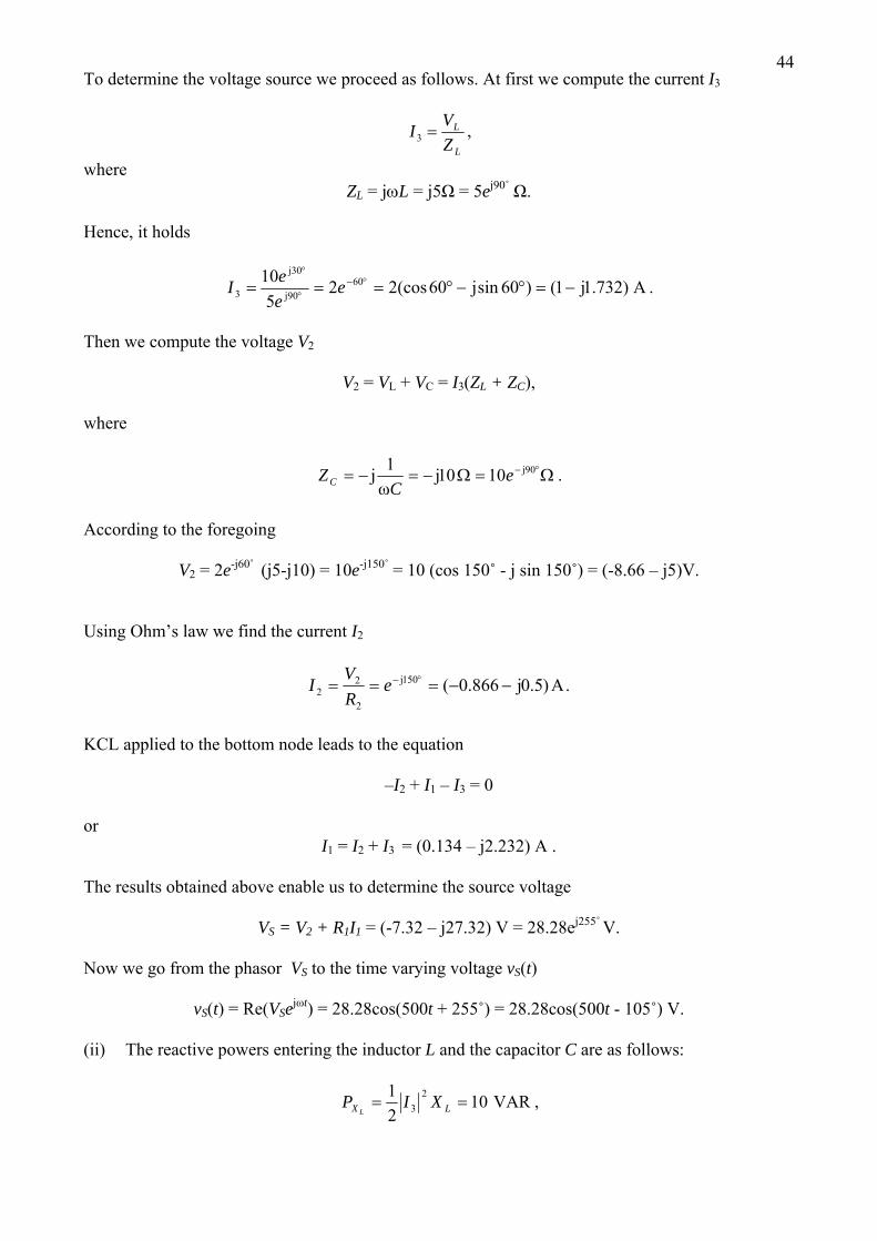
(iii) A phasor diagram is sketched in Fig. 3.
I3
V2=VL+VC I2
VL
VC
VS
I1
I1R1
Fig. 3
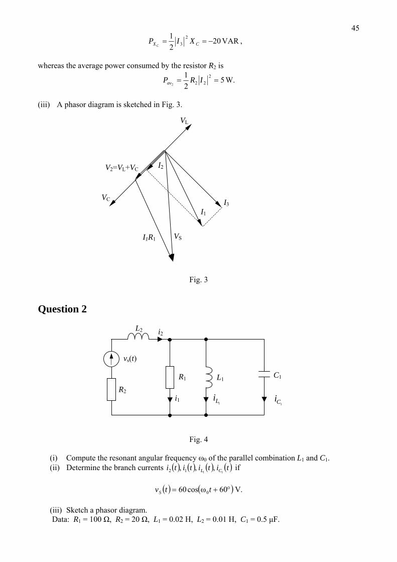
Question 2
1Li
i2 L2
i1 1Ci
vs(t)
C1 L1 R1
R2
Fig. 4
(i) Compute the resonant angular frequency ω0 of the parallel combination L1 and C1. (ii) Determine the branch currents ( ) ( ) ( ) ( )titititi CL 11
,,, 12 if
( ) ( ) .60cos60 0 Vω °+= ttvS
(iii) Sketch a phasor diagram. Data: R1 = 100 Ω, R2 = 20 Ω, L1 = 0.02 H, L2 = 0.01 H, C1 = 0.5 μF.
46Solution
(i) The resonant angular frequency is given by
⋅=⋅⋅⋅
==ω−− s
rad4
6211
0 10105.0102
11CL
(ii) We redraw the circuit in the phasor format (see Fig. 5).
1CI
V1 1LZ
I2 I = 0
VS
R2 1CZR1
2LZ1LII1
Fig. 5
Having vs(t) we find the voltage source phasor
.60 60 Vj °=sV
Since at resonance I = 0, the same current I1 = I2 traverses and V21 ,,2
RZR L S. Hence, we have
Aj
jj
°°
=+
=++
== 2.2060
1212 384.0
10012060
2
eeRZR
VII
L
s
and in the time domain
( ) ( ) ( ) ( ) .A j °+=== ω 2.2010cos384.0Re 4212 teItiti t
To determine the current we find the voltage V
1LI 1
Vj °== 2.20111 4.38 eIRV
and apply Ohm’s law
.192.0200
4.38 8.6990
2.20
1
11
Ajω
jj
j
o
°−°
°
=== eee
LVI L
Hence, we obtain
( ) ( ) ( ) .8.6910cos192.0Re 411
Aj °−== ω teIti tLL
Since at resonance ( ) ( )titi cL −=
1 then
47( ) ( ) ( ) .2.11010cos1921808.6910cos192.0 44 A°+=°+°−= tttci
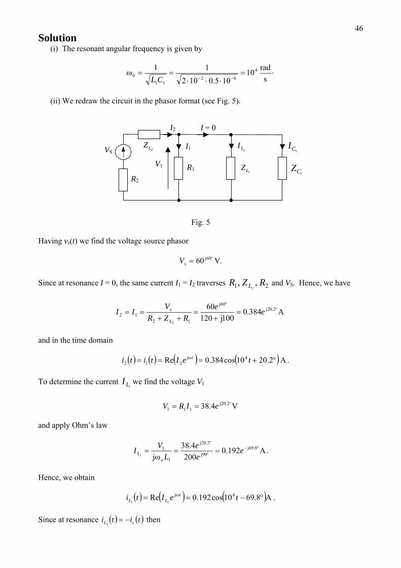
(i) A phasor diagram is sketched in Fig. 6
1CI V1=I2R1
I2=I1
1LI
VS
I2jωoL2
I2(R1+R2)
Fig. 6
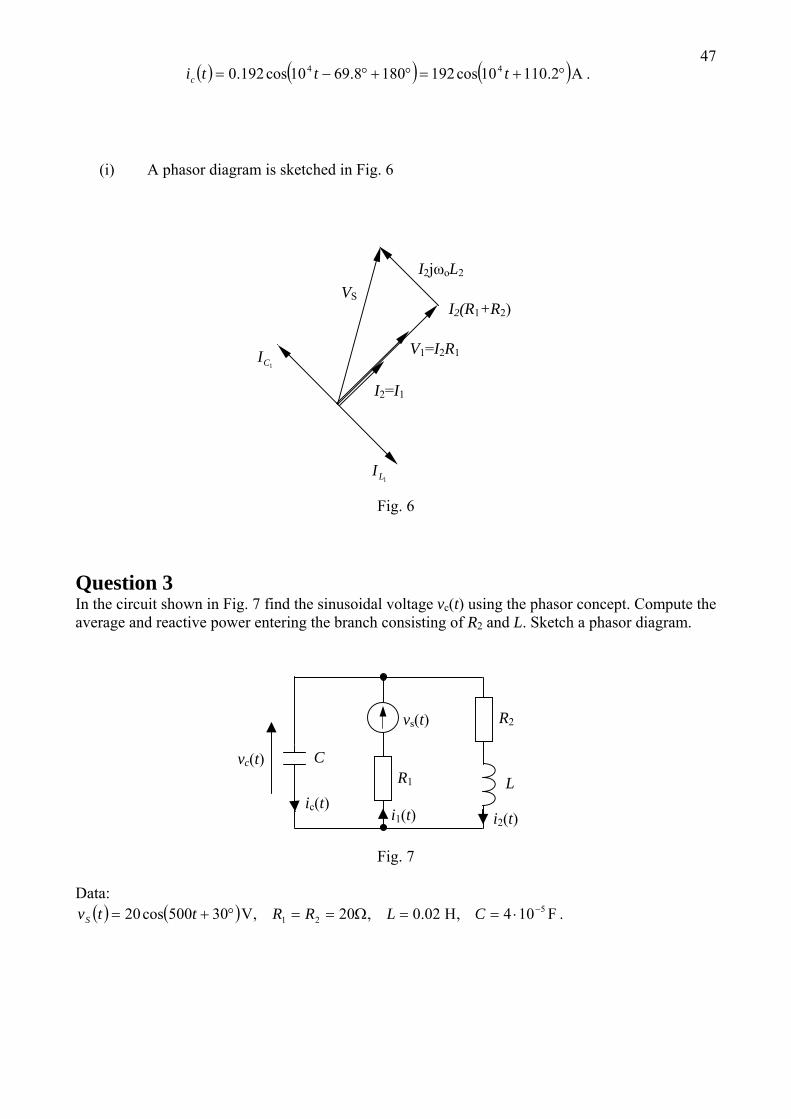
Question 3 In the circuit shown in Fig. 7 find the sinusoidal voltage vc(t) using the phasor concept. Compute the average and reactive power entering the branch consisting of R2 and L. Sketch a phasor diagram.
ic(t)
vc(t)
i2(t)i1(t)
vs(t)
C
LR1
R2
Fig. 7
Data: ( ) ( ) .104,02.0,20,30500cos20 5
21 FHV −⋅==Ω==°+= CLRRttvS
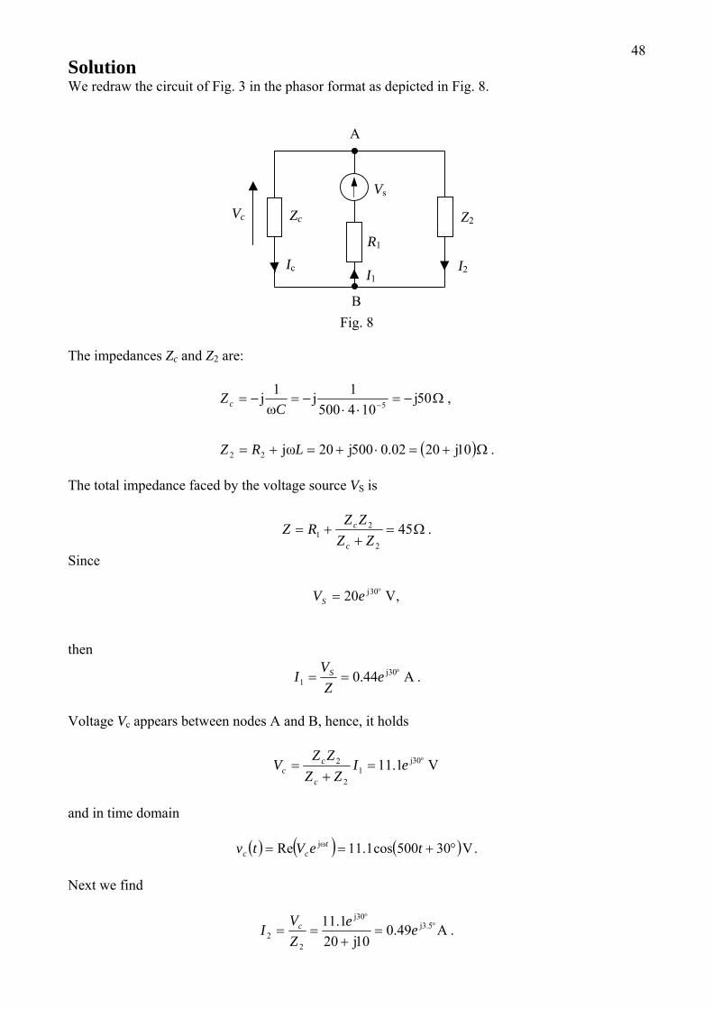
48Solution We redraw the circuit of Fig. 3 in the phasor format as depicted in Fig. 8.
B
Ic
Vc
I2 I1
Vs
A
Zc
R1
Z2
Fig. 8
The impedances Zc and Z2 are:
( ) .102002.050020
,50104500
11
22
5
Ω+=⋅+=+=
Ω−=⋅⋅
−=−= −
jjjω
jjω
j
LRZ
CZc
The total impedance faced by the voltage source VS is
.452
21 Ω=
++=
ZZZZ
RZc
c
Since
,20 30j V°= eVS
then
.44.0 301 Aj °== e
ZV
I S
Voltage Vc appears between nodes A and B, hence, it holds
Vj °=+
= 301
2
2 1.11 eIZZ
ZZV
c
cc
and in time domain
( ) ( ) ( ) .30500cos1.11Re Vjω °+== teVtv tcc
Next we find
.49.01020
1.11 5.330
22 A
jj
j°
°
=+
== eeZV
I c
49
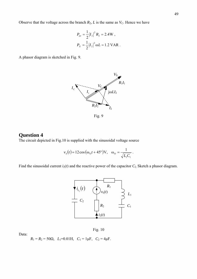
Observe that the voltage across the branch R2, L is the same as VC. Hence we have
.2.121
,4.221
22
22
2
VAR
W
=ω=
==
LIP
RIP
X
av
A phasor diagram is sketched in Fig. 9.
CIR1I1
I2
1I
VS
jωLI2
R2I2
VC
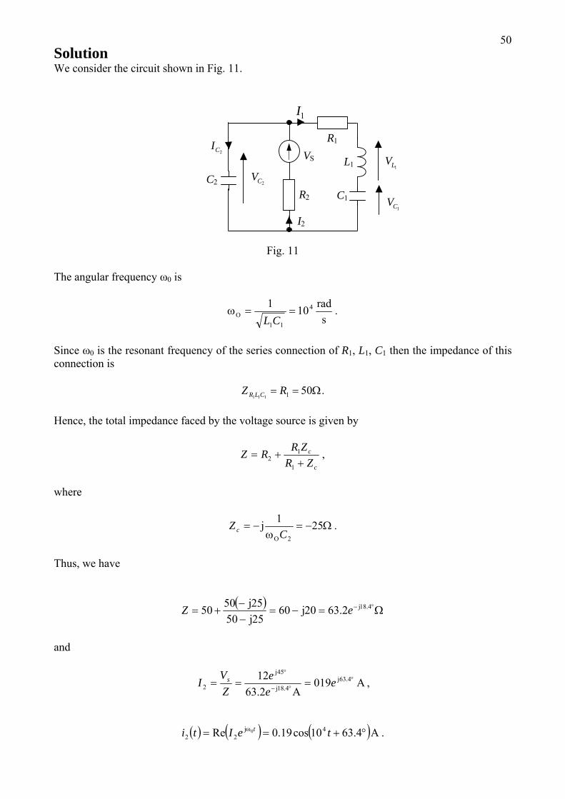
Fig. 9 Question 4 The circuit depicted in Fig.10 is supplied with the sinusoidal voltage source
( ) ( ) .1,45cos1211CL
ttvS =°+= OO ωVω
Find the sinusoidal current i2(t) and the reactive power of the capacitor C2. Sketch a phasor diagram.
C1
( )tic2
i2(t)
vs(t)
C2
L1
R2
R1
Fig. 10
Data: R1 = R2 = 50Ω, L1=0.01H, C1 = 1μF, C2 = 4μF.
50Solution We consider the circuit shown in Fig. 11.
1I
2CV
1CV
1LV
C1
2CI
I2
VS
C2
L1
R2
R1
Fig. 11
The angular frequency ω0 is
.101 4
11 srad
O ==ωCL
Since ω0 is the resonant frequency of the series connection of R1, L1, C1 then the impedance of this connection is
.501111Ω== RZ CLR
Hence, the total impedance faced by the voltage source is given by
,1
12
c
c
ZRZRRZ+
+=
where
.251
2
Ω−=ω
−=C
Z cO
j
Thus, we have
( )Ω=−=
−−
+= °− 4.182.6320602550255050 jjjj eZ
and
AA
j8.4j
j°
°−
°
=== 4.631
45
2 0192.6312 e
ee
ZV
I s ,
( ) ( ) ( ) .4.6310cos19.0Re 422
0 Aj °+== ω teIti t
51 Next we compute voltage using KVL:
2CV
VIRVV SC 23.4222=−= .
To find the reactive power of the capacitor C2 we use the relationship
,21 2
2CX VBP −=
where
.04.020 SCB =ω=
Hence, we obtain
.36.0 VARPX −=
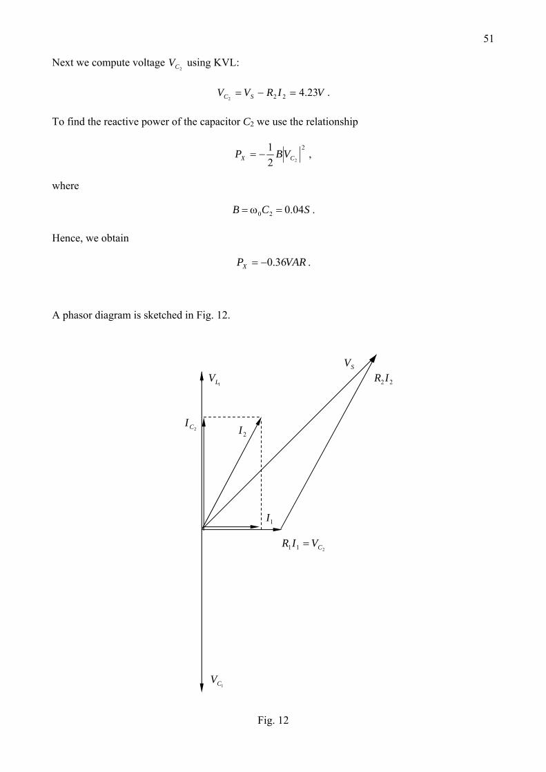
A phasor diagram is sketched in Fig. 12.
1CV
1I
211 CVIR =
22IR SV
2I 2CI
1LV
Fig. 12
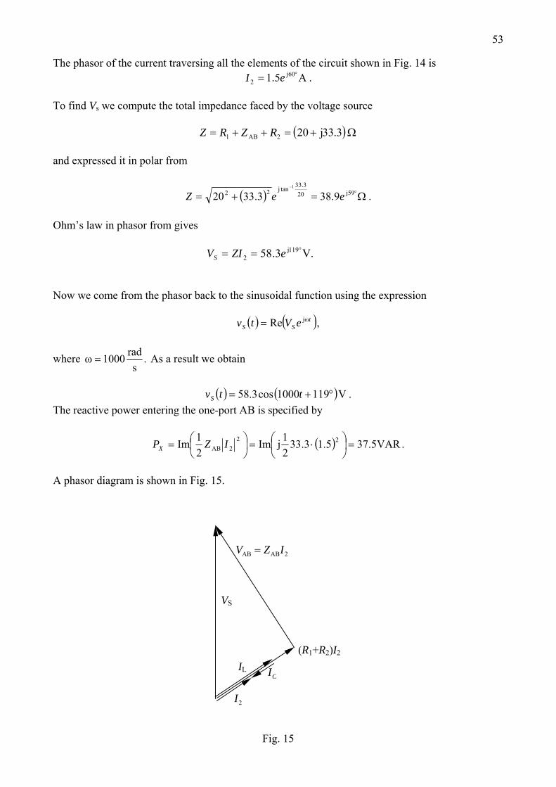
52Question 5 In the circuit depicted in Fig. 13 determine the sinusoidal source voltage vS(t) if
( ) ( ) .601000cos5.12 V°+= tti
Compute the reactive power entering the one-port AB. Sketch a phasor diagram.
( )tiL
B C
( )tiC
i2(t) ( )tvS
A
L
R2
R1
Fig. 13
Data: .102,02.0,10 5
21 FH −⋅==Ω== CLRR Solution Let us redraw the circuit using the phasor format as depicted in Fig. 14, where
( ) .3.3330
50201
1
Ω=−−
=
ω−ω
⎟⎠⎞
⎜⎝⎛
ω−
= jj
jj
jj
jjωAB
CL
CL
Z
B
VABI2
sV
A ZAB
R2
R1
Fig. 14
53
The phasor of the current traversing all the elements of the circuit shown in Fig. 14 is .5.1 60
2 Aj °= eI
To find Vs we compute the total impedance faced by the voltage source
( )Ω+=++= 3.332021 jAB RZRZ
and expressed it in polar from
( ) .9.383.3320 59203.33tan22
1
Ω=+= °−
jjeeZ
Ohm’s law in phasor from gives
.3.58 119
2 Vj °== eZIVS
Now we come from the phasor back to the sinusoidal function using the expression
( ) ( ),Re tSS eVtv jω=
where .1000s
radω = As a result we obtain
( ) ( ) .1191000cos3.58 V°+= ttvS
The reactive power entering the one-port AB is specified by
( ) .5.375.13.3321Im
21Im 22
2 VARjAB =⎟⎠⎞
⎜⎝⎛ ⋅=⎟
⎠⎞
⎜⎝⎛= IZPX
A phasor diagram is shown in Fig. 15.
CI
(R1+R2)I2
IL
2I
VS
2IZV ABAB =
Fig. 15
54
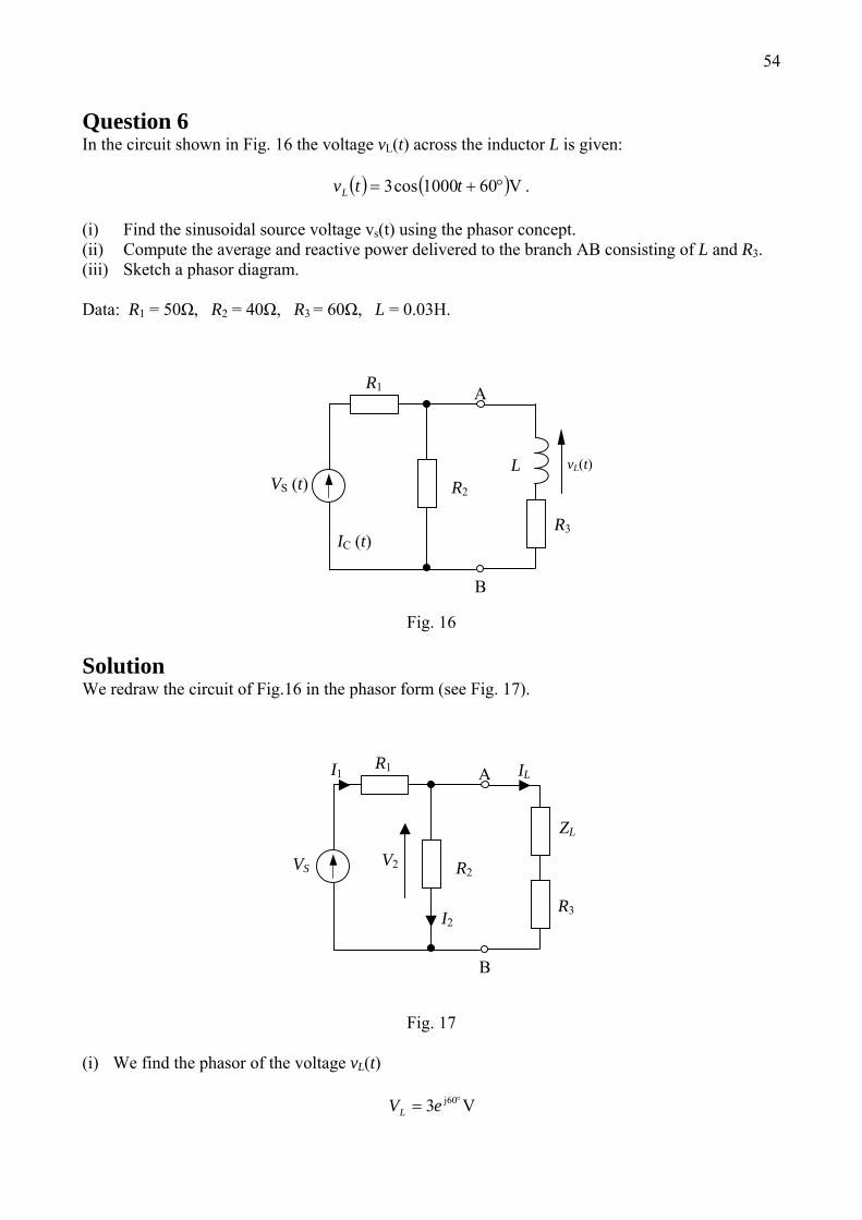
Question 6 In the circuit shown in Fig. 16 the voltage vL(t) across the inductor L is given:
( ) ( ) .601000cos3 V°+= ttvL
(i) Find the sinusoidal source voltage vs(t) using the phasor concept. (ii) Compute the average and reactive power delivered to the branch AB consisting of L and R3. (iii) Sketch a phasor diagram. Data: R1 = 50Ω, R2 = 40Ω, R3 = 60Ω, L = 0.03H.
vL(t)
IC (t)R3
B
VS (t)
A
L
R1
R2
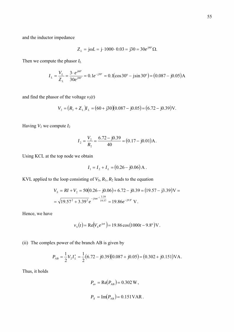
Fig. 16 Solution We redraw the circuit of Fig.16 in the phasor form (see Fig. 17).
V2
I2
I1 IL
R3
B
VS
A
ZL
R1
R2
Fig. 17
(i) We find the phasor of the voltage vL(t)
Vj °= 603eVL
55
and the inductor impedance
.303003.01000 90 Ω==⋅⋅== °jjjjω eLZ L
Then we compute the phasor IL
( ) ( Ajjjj
j
05.0087.030sin30cos1.01.0303 30
90
60
−=°−°==⋅
== °−°
°
eee
ZVI
L
LL )
and find the phasor of the voltage v2(t)
( ) ( )( ) ( ) .39.072.605.0087.0306032 Vjjj −=−+=+= LL IZRV
Having V2 we compute I2
( ) .01.017.040
39.072.6
2
22 Ajj
−=−
==RVI
Using KCL at the top node we obtain
( ) .06.026.021 Aj−=+= LIII
KVL applied to the loop consisting of VS, R1, R2 leads to the equation
( ) ( )
.86.1939.357.19
39.357.1939.072.606.026.050
8.957.1939.3tan22
2
1
V
Vjjj
jj °−−=+=
=−=−+−=+=−
ee
VRIVS
Hence, we have
( ) ( ) ( ) .8.91000cos86.19Re Vjω °−== teVtv tSS
(ii) The complex power of the branch AB is given by
( )( ) ( .151.0302.005.0087.039.072.621
21
2 VAjjjAB +=+−== ∗LIVP )
Thus, it holds
( )
( ) .151.0
,302.0Re
VARIm
W
AB
AB
==
==
PP
PP
X
av
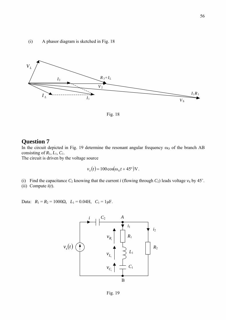
56 (i) A phasor diagram is sketched in Fig. 18
LIV S
I1R 1
R 3+ ILI2
LV
I1
V 2
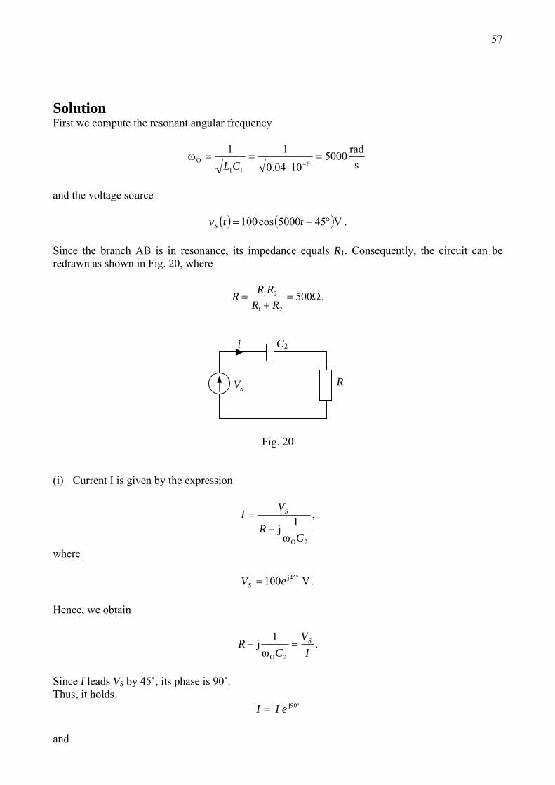
Fig. 18 Question 7 In the circuit depicted in Fig. 19 determine the resonant angular frequency ωO of the branch AB consisting of R1, L1, C1. The circuit is driven by the voltage source
( ) ( ) .45cos100 VO °+ω= ttvS
(i) Find the capacitance C2 knowing that the current i (flowing through C2) leads voltage vS by 45˚. (ii) Compute i(t). Data: R1 = R2 = 1000Ω, L1 = 0.04H, C1 = 1μF.
1Rv
i
i1
C1
1Lv
B
C2
1Cv
i2
( )tvs
A
L1
R2
R1
Fig. 19
57
Solution First we compute the resonant angular frequency
srad
O 50001004.0
116
11
=⋅
==ω−CL
and the voltage source
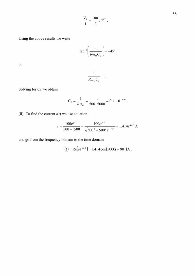
( ) ( ) .455000cos100 V°+= ttvS Since the branch AB is in resonance, its impedance equals R1. Consequently, the circuit can be redrawn as shown in Fig. 20, where
.50021
21 Ω=+
=RR
RRR
i C2
SV R
Fig. 20
(i) Current I is given by the expression
,1
2CR
VI S
Oωj−
=
where
.100 45 Vj °= eVS Hence, we obtain
.1
2 IV
CR S=−
Oωj
Since I leads VS by 45˚, its phase is 90˚. Thus, it holds
°= 90jeII
and
58
.100 45°−= jeII
VS
sing the above results we write U
°−=⎟⎟⎠
⎞⎜⎜⎝
⎛ −− 451tan2
1
CR Oω
or
.11
2
=CR Oω
Solving for C2 we obtain
.104.05000500
11 62 F
ωO
−⋅=⋅
==R
C
(ii) To find the current i(t) we use equation
Aj
j
j
jj°
°−
°°
=+
=−
= 90
4522
4545
414.1500500
100500500
100 ee
eeI
and go from the frequency domain to the time domain
( ) ( ) ( ) .905000cos414.1Re AOjω °+== tIeti t
59
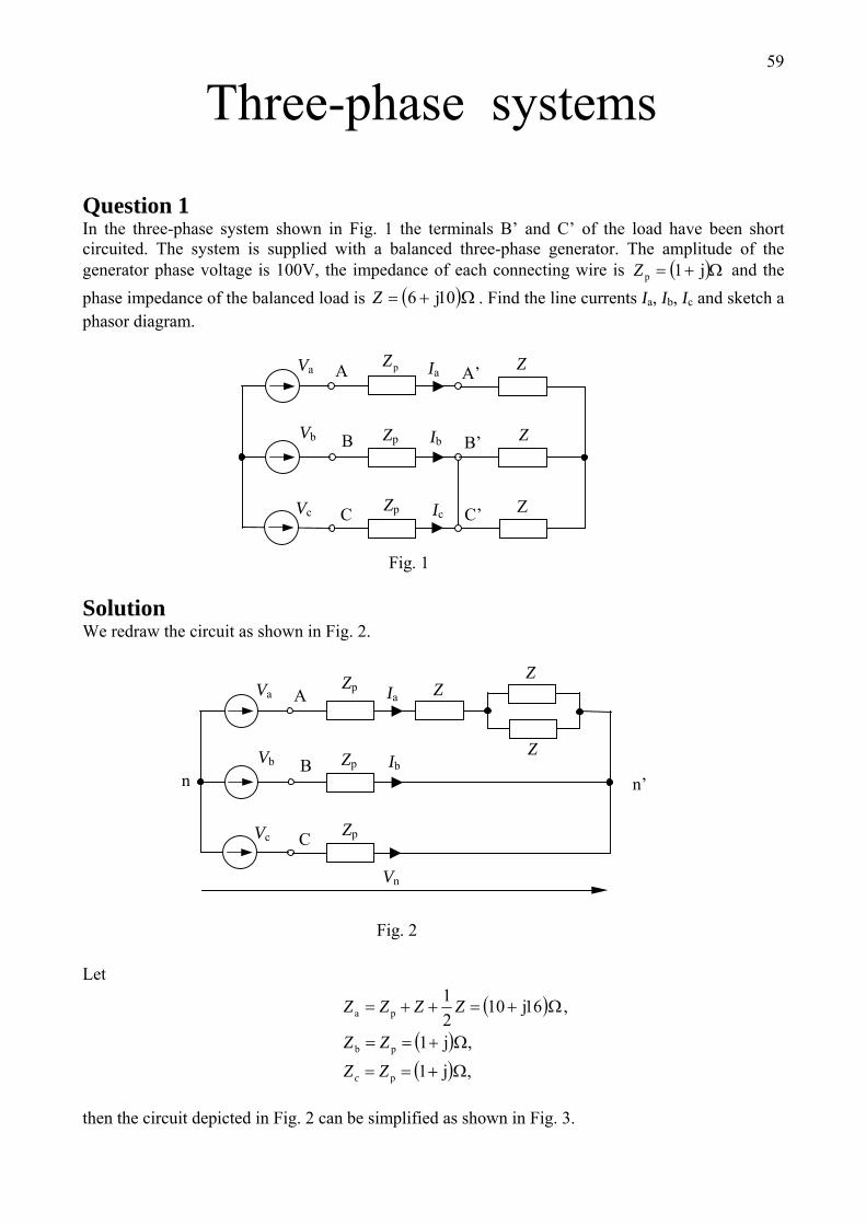
Three-phase systems
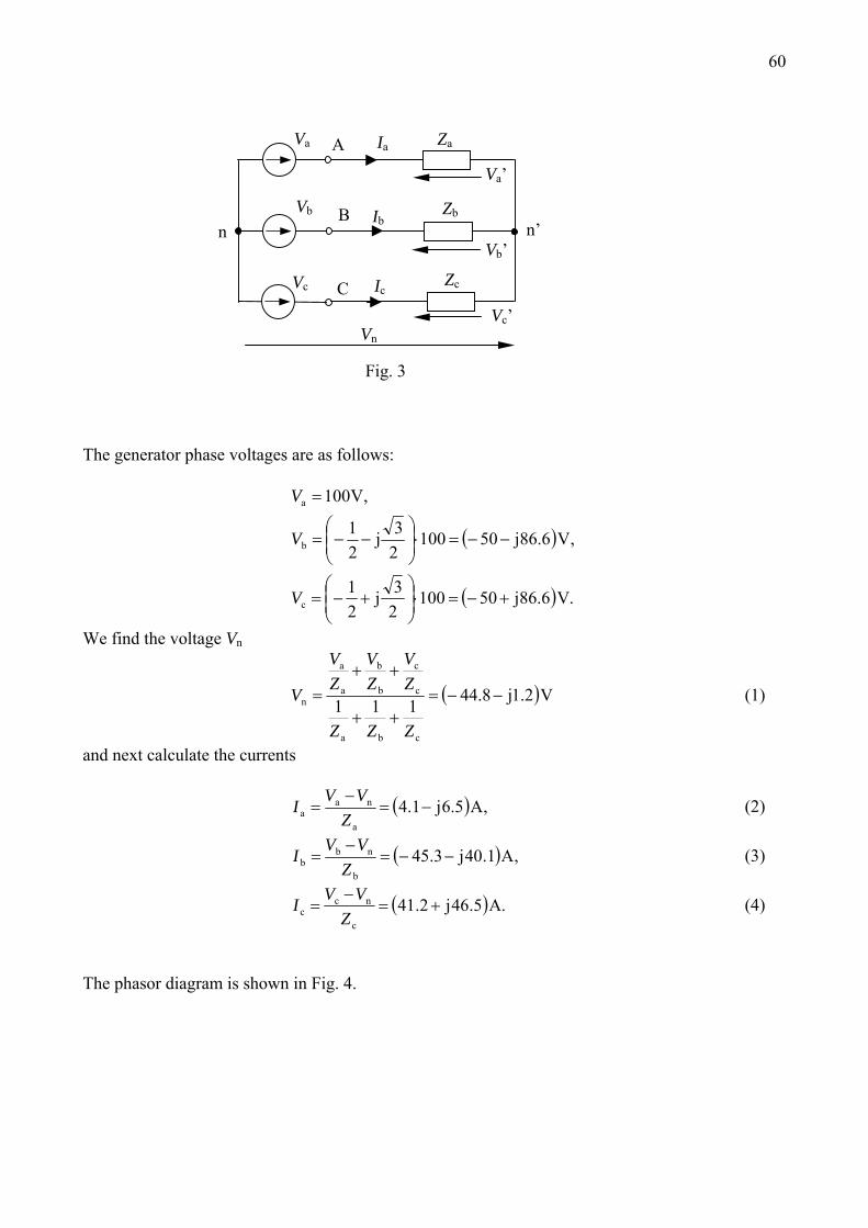
Question 1 In the three-phase system shown in Fig. 1 the terminals B’ and C’ of the load have been short circuited. The system is supplied with a balanced three-phase generator. The amplitude of the generator phase voltage is 100V, the impedance of each connecting wire is and the phase impedance of the balanced load is
( )Ω+= jp 1Z( )Ω+= 106 jZ . Find the line currents Ia, Ib, Ic and sketch a
phasor diagram.
C’
B’
A’
Vc IcC
B
A
Z
Z
Va pZ
Ib
Z
Vb
Zp
Zp
Ia
Fig. 1 Solution We redraw the circuit as shown in Fig. 2.
Z
n’ n
Vc
Vn
C
B
A
Z
Va Zp
Ib
Z
Vb
Zp
Zp
Ia
Fig. 2 Let
( )
( )( ) ,1
,1
,161021
Ω+==
Ω+==
Ω+=++=
j
j
j
p
pb
pa
ZZ
ZZ
ZZZZ
c
then the circuit depicted in Fig. 2 can be simplified as shown in Fig. 3.
60
Vc’
Vb’
Va’
Ic
n Ib
Vc C
B
A
Vn
n’
Va
Zb
Ia
Vb
Zc
Za
Fig. 3 The generator phase voltages are as follows:
( )
( ) .Vjj
,Vjj
,V
c
b
a
6.865010023
21
6.865010023
21
100
+−=⋅⎟⎟⎠
⎞⎜⎜⎝
⎛+−=
−−=⋅⎟⎟⎠
⎞⎜⎜⎝
⎛−−=
=
V
V
V
We find the voltage Vn
( Vj
cba
c
c
b
b
a
a
n 2.18.44111 −−=++
++=
ZZZ
ZV
ZV
ZV
V ) (1)
and next calculate the currents
( ,A6.5ja
naa −=
−= 1.4
ZVVI ) (2)
( ,Ajb
nbb 1.403.45 −−=
−=
ZVVI ) (3)
( .5.462.41 Ajc
ncc +=
−=
ZVVI ) (4)
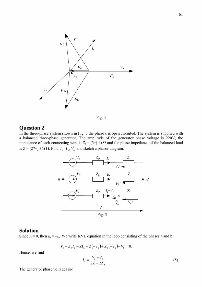
The phasor diagram is shown in Fig. 4.
61
Ib V’b
Vb
V’a
Va
Ia
Vn
Ic
V’c
Vc
Fig. 4
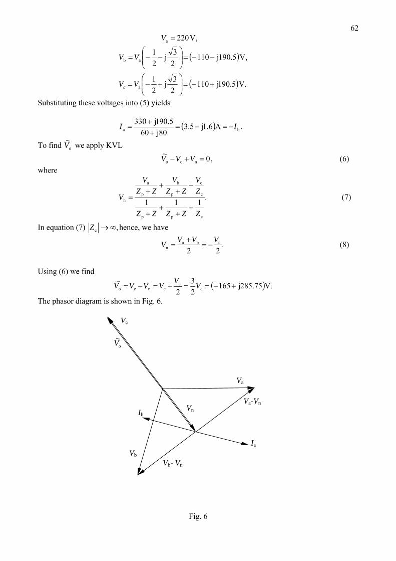
Question 2 In the three-phase system shown in Fig. 5 the phase c is open circuited. The system is supplied with a balanced three-phase generator. The amplitude of the generator phase voltage is 220V, the impedance of each connecting wire is Zp = (3+j 4) Ω and the phase impedance of the balanced load is Z = (27+j 36) Ω. Find oba VII ~,, and sketch a phasor diagram.
Vn oV~ Vc’
Va’
Zp
Vc Ic= 0
Vb’n’ n
Z
Z
Va
Ib
Z
Vb
Zp
Zp
Ia
Fig. 5 Solution Since Ic = 0, then Ib = –Ia. We write KVL equation in the loop consisting of the phases a and b: ( ) ( ) .0=−−+−+−− bapaaapa VIZIZZIIZV Hence, we find
.p
baa 22 ZZ
VVI+−
= (5)
The generator phase voltages are
62, Va 220=V
( )
( ) .Vjj
,Vj23j
21
a
ab
5.19011023
21
5.190110
+−=⎟⎟⎠
⎞⎜⎜⎝
⎛+−=
−−=⎟⎟⎠
⎞⎜⎜⎝
⎛−−=
VV
VV
c
Substituting these voltages into (5) yields
( ) .6.15.35.190330ba Aj
j8060j II −=−=++
=
To find oV~ we apply KVL
,0~ =+− nco VVV (6) where
.111
cpp
c
c
p
b
p
a
n
ZZZZZ
ZV
ZZV
ZZV
V+
++
+
++
++
= (7)
In equation (7) ,∞→cZ hence, we have
.2 2
cban
VVVV −=+
= (8)
Using (6) we find
( ) .Vjcc
cnco 75.28516523
2~ +−==+=−= VVVVVV
The phasor diagram is shown in Fig. 6.
Ib
Vb- Vn
Vb
Va-Vn
Va
Ia
Vn
oV~
Vc
Fig. 6
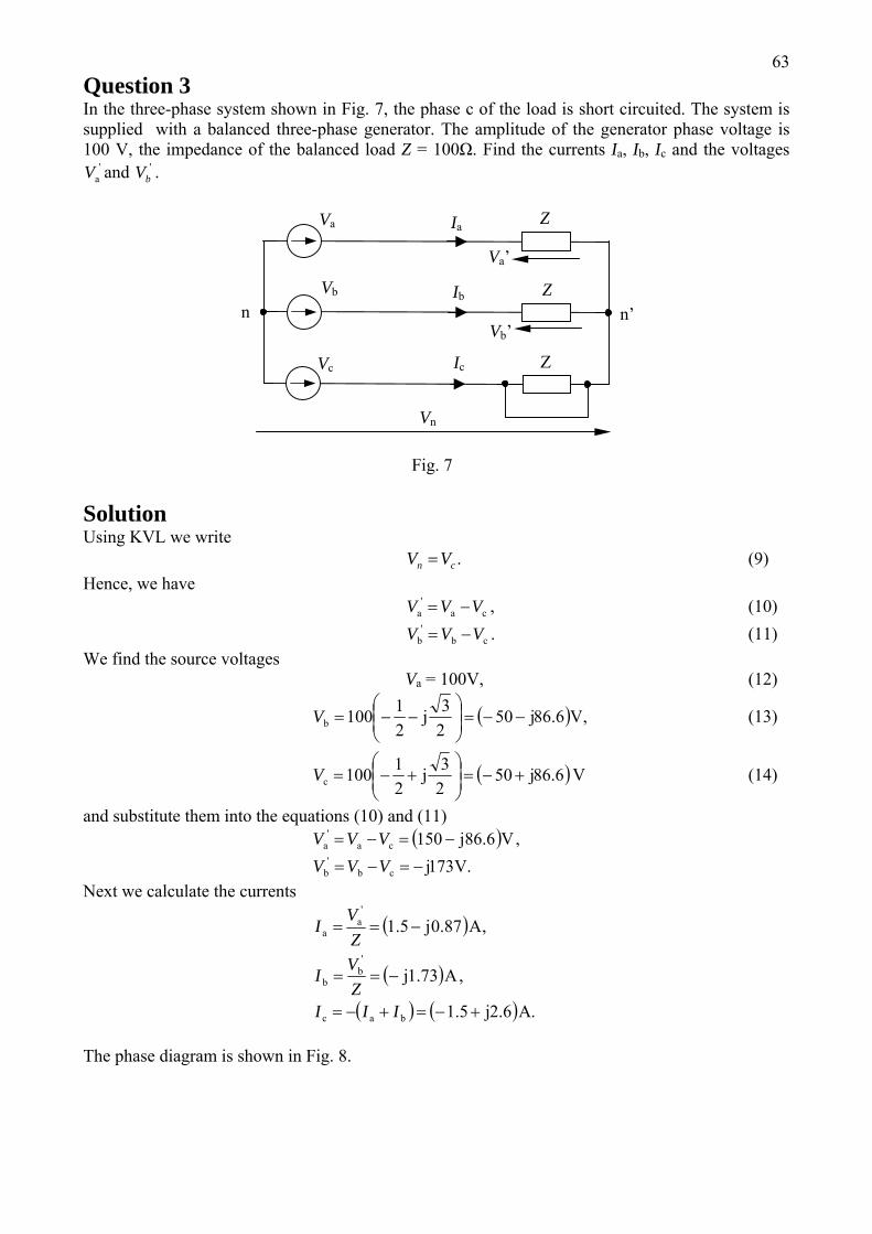
63Question 3 In the three-phase system shown in Fig. 7, the phase c of the load is short circuited. The system is supplied with a balanced three-phase generator. The amplitude of the generator phase voltage is 100 V, the impedance of the balanced load Z = 100Ω. Find the currents Ia, Ib, Ic and the voltages
and . 'aV '
bV
Vn
Va’
Vc Ic
Vb’n’ n
Z
Z
Va
Ib
Z
Vb
Ia
Fig. 7 Solution Using KVL we write .cn VV = (9) Hence, we have , (10) ca
'a VVV −=
(11) .cb'
b VVV −=We find the source voltages Va = 100V, (12)
( ,6.865021100 Vj
23jb −−=⎟⎟⎠
⎞⎜⎜⎝
⎛−−=V ) (13)
( 86.6j23jc +−=⎟⎟⎠
⎞⎜⎜⎝
⎛+−= 50
21100V )V (14)
and substitute them into the equations (10) and (11) ( ) ,V86.6jca
'a −=−= 150VVV
V.173jcbb −=−= VVV '
Next we calculate the currents
( )
( )
( ) ( ) .5.1
5.1
A2.6j
,A1.73j
,A0.87j
bac
'b
b
'a
a
+−=+−=
−==
−==
IIIZVI
ZVI
The phase diagram is shown in Fig. 8.
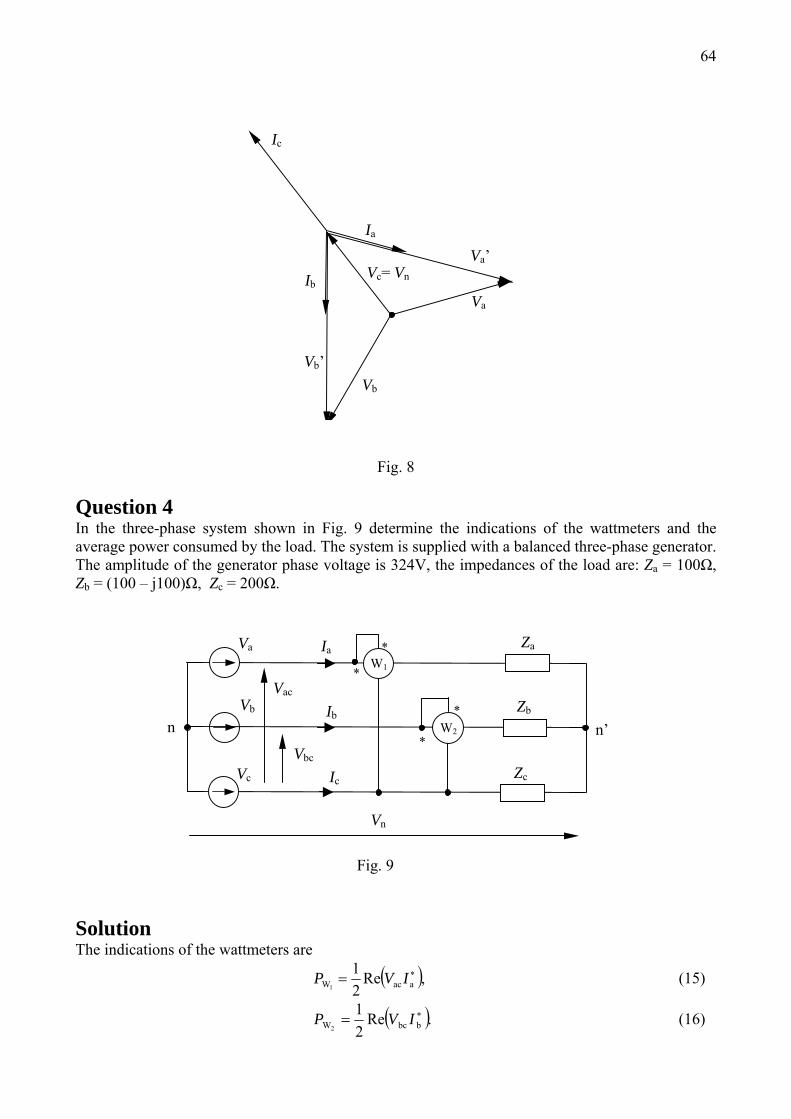
64
Ic
Vc= Vn
Vb
Vb’
Va
Ia
Va’Ib
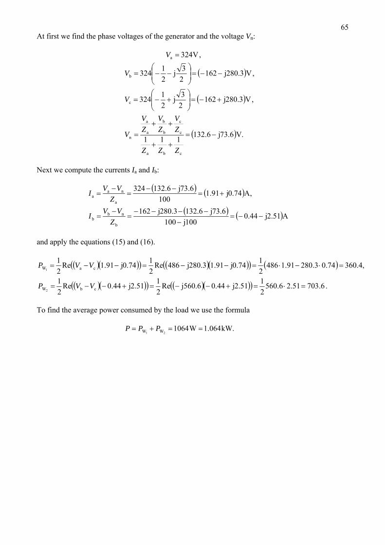
Fig. 8 Question 4 In the three-phase system shown in Fig. 9 determine the indications of the wattmeters and the average power consumed by the load. The system is supplied with a balanced three-phase generator. The amplitude of the generator phase voltage is 324V, the impedances of the load are: Za = 100Ω, Zb = (100 – j100)Ω, Zc = 200Ω.
*
*
*
*
Vn
Vac
Vc Ic
Vbc n’ n
Zc
Zb
Va
Ib
Za
Vb
Ia
Fig. 9
W1
W2
Solution The indications of the wattmeters are
( ),Re21 ∗= aacW1
IVP (15)
( ).Re21 ∗= bbcW2
IVP (16)
65
,
At first we find the phase voltages of the generator and the voltage Vn: Va 324=V
( )
( )
( ) .V73.6j1
,V280.3j23j
,V280.3j23j
cba
c
c
b
b
a
a
n
c
b
−=++
++=
+−=⎟⎟⎠
⎞⎜⎜⎝
⎛+−=
−−=⎟⎟⎠
⎞⎜⎜⎝
⎛−−=
6.13211
16221324
16221324
ZZZ
ZV
ZV
ZV
V
V
V
Next we compute the currents Ia and Ib:
( ) ( )
( ) ( )Ajj100
j132.6280.3j
,A0.74j73.6j
b
nbb
a
naa
51.244.0100
6.73162
91.1100
6.132324
−−=−
−−−−=
−=
+=−−
=−
=
ZVVI
ZVVI
and apply the equations (15) and (16).
( )( )( ) ( )( )( ) ( )
( )( )( ) ( )( )( ) .6.70351.26.5602144.0Re
2144.0Re
21
,4.36074.03.28091.14862191.1486Re
2191.1Re
21
=⋅=+−−=+−−=
=⋅−⋅=−−=−−=
2.51jj560.62.51j
0.74j280.3j0.74j
cbW
caW
2
1
VVP
VVP
To find the average power consumed by the load we use the formula kW.1.064W
21 WW ==+= 1064PPP