electric multi-turn actuators - pt. central automatic sa.pdfmulti-turn actuators sa 07.1 – sa 48.1...
TRANSCRIPT
Electric multi-turn actuators
Product descriptionCertificate Registration No.
12 100/104 4269
for open-close and modulating dutySA 07.1 – SA 48.1
SAR 07.1 – SAR 30.1SAEx(C) 07.1 – SAEx(C) 40.1SARExC 07.1 – SARExC 16.1
2
In the course of constantly increas-ing automation in all sectors of indus-try, electric actuators for processcontrol and regulation have becomemore and more important.
For more than 40 years AUMA con-centrates on design, developmentand production of electric actuators.During this time AUMA has acquireda know-how in this field that canhardly be surpassed. AUMA is aleading electric actuator manufactur-ers world-wide.
Sales support and after sales serviceare provided by a global networkconsisting of regional offices, sub-sidiaries, representatives and ser-vice centres. This ensures that expe-rienced sales engineers and quali-fied service technicians are close tothe customers. They are preparedfor responding to enquiries, execut-ing orders or providing after-salesservice.
With this brochure AUMA offers acomplete overview of design, func-tions and equipment of the multi-turnactuator type ranges SA and SAR.Further information can be found onseparate data sheets and price lists.
Detailed and up-to-date informationon the multi-turn actuators SA andSAR can be found on the Internetunder www.auma.com. All docu-ments, including dimension draw-ings, wiring diagrams and finalinspection records for suppliedmulti-turn actuators are available onthe Internet in digitalised form.
Table of contentsApplications 3Versions 5Summary of equipment / functions 6Equipment / Functions 7
Type designation 7Open-close duty 7Modulating duty 8Comparison short-time and intermittent duty 9Seating 10Setting range of tripping torque / Torques for modulating duty 10Overload protection against torque peaks 11DUO limit switching / intermediate position switches (option) 11Limit and torque switches 12Non-intrusive setting (option) 12Magnetic limit and torque transmitter (MWG) (option) 13Position/ torque feedback signal (option) 14Mechanical position indicator (option) 14Running indication 14Heater 15Locking device for manual operation (option) 15Wiring diagrams 15
Design principle 16Equipment / Functions 18
Motors 18Motor protection 19
Output speeds 20Actuator controls 21
Integral controls (option) 21Which type of controls? 22Advantages integral controls (option) 23
Interfaces 24Electrical connection 24Valve attachment 26Output drive types 26
Service conditions 27Enclosure protection 27Corrosion protection / Colour 27Ambient temperatures 27Explosion protection 28Lifetime 28Other service conditions 28
Combinations Multi-turn actuators / Gearboxes 29Combinations with bevel or spur gearboxes 29Combinations with worm gearboxes 29Combinations with lever gearboxes 29Combinations with linear thrust units 29
Other information 30EU-Directives 30Functional tests 30Further literature 30
Index 31
Subject to change without notice. The product features and technical data provideddo not express or imply any warranty.

3
Applications
Energy ■ Power plants■ Air pollution control■ District heating
AUMA multi-turn actuators of the type ranges SAand SAR can be used wherever the automation ofa valve requires a rotation. The adaption to therequirements of nearly every valve automationtask is possible. This is achieved by:
■ an extremely wide torque range,■ various combination possibilities with AUMA
valve gearboxes. Thereby the torque rangecan be further extended and/ or the multi-turnactuator can be modified into a part-turn, leveror linear actuator
■ a large variety of versions. Whether for openloop or closed loop control or explosion-proofapplications, a suitable version is available forevery requirement.
Chemicalindustry
■ Chemical industry■ Petrochemical industry■ Pharmaceutical industry
Pipelines Others ■ Air conditioning■ Ship building industry■ Steel mills■ Cement plants■ Food industry
Water/Wastewater
■ Water works■ Sewage treatment plants■ Pump stations■ Locks■ Dams
4
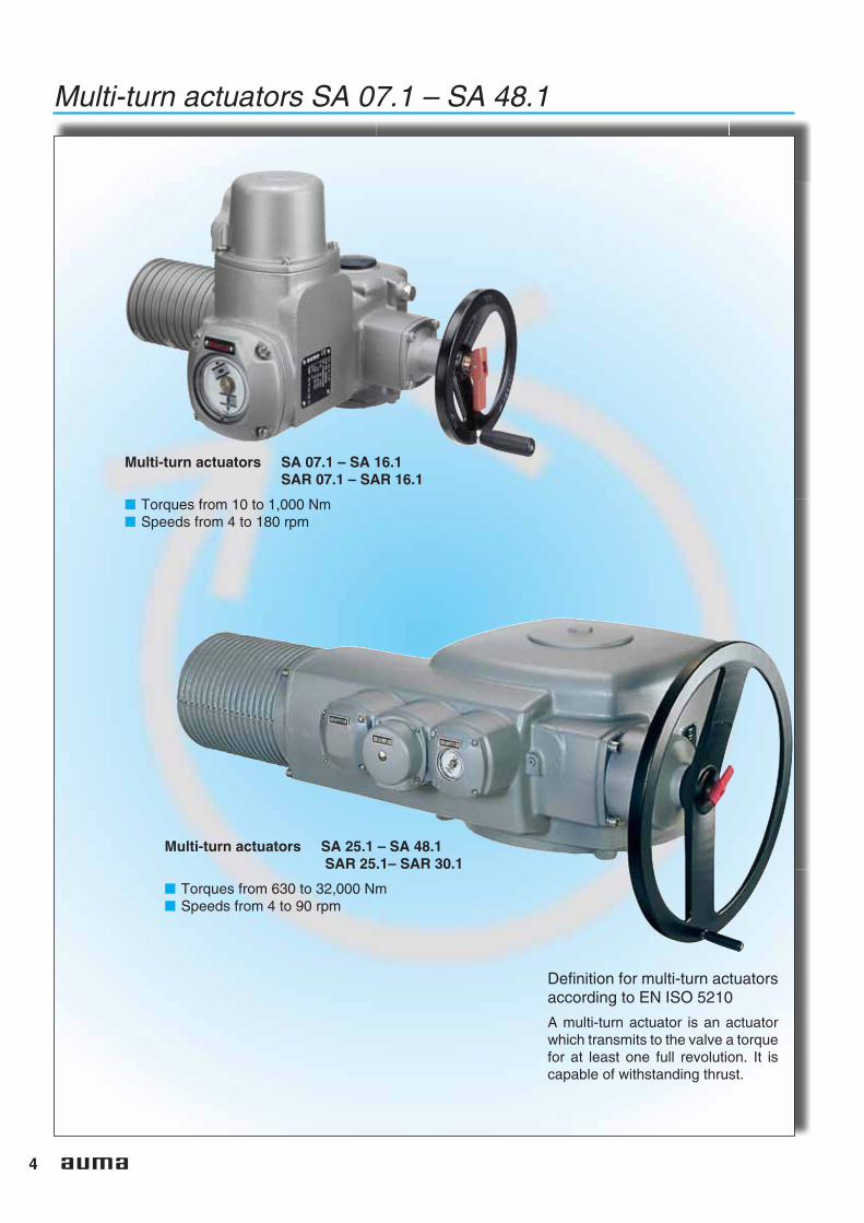
Multi-turn actuators SA 07.1 – SA 48.1
Definition for multi-turn actuatorsaccording to EN ISO 5210
A multi-turn actuator is an actuatorwhich transmits to the valve a torquefor at least one full revolution. It iscapable of withstanding thrust.
Multi-turn actuators SA 07.1 – SA 16.1SAR 07.1 – SAR 16.1
■ Torques from 10 to 1,000 Nm■ Speeds from 4 to 180 rpm
Multi-turn actuators SA 25.1 – SA 48.1SAR 25.1– SAR 30.1
■ Torques from 630 to 32,000 Nm■ Speeds from 4 to 90 rpm
5
Versions
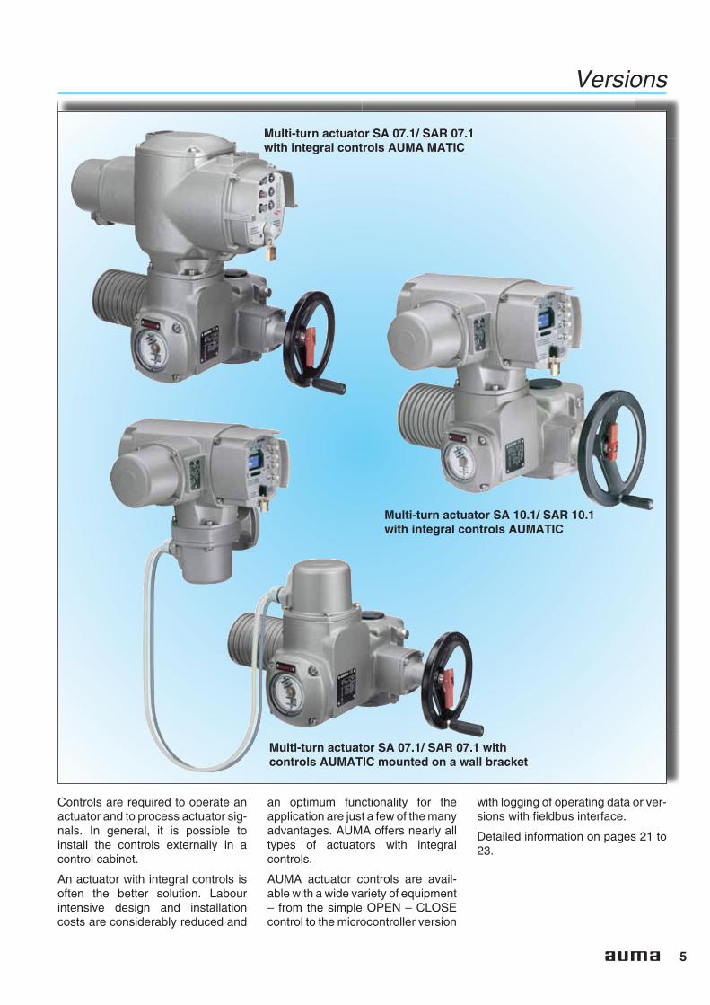
Controls are required to operate anactuator and to process actuator sig-nals. In general, it is possible toinstall the controls externally in acontrol cabinet.
An actuator with integral controls isoften the better solution. Labourintensive design and installationcosts are considerably reduced and
an optimum functionality for theapplication are just a few of the manyadvantages. AUMA offers nearly alltypes of actuators with integralcontrols.
AUMA actuator controls are avail-able with a wide variety of equipment– from the simple OPEN – CLOSEcontrol to the microcontroller version
with logging of operating data or ver-sions with fieldbus interface.
Detailed information on pages 21 to23.
Multi-turn actuator SA 10.1/ SAR 10.1with integral controls AUMATIC
Multi-turn actuator SA 07.1/ SAR 07.1 withcontrols AUMATIC mounted on a wall bracket
Multi-turn actuator SA 07.1/ SAR 07.1with integral controls AUMA MATIC

6
Summary of equipment/ functions● Standard■ Option
SA07.1 - 48.1
SAR07.1 – 30.1
SAEx(C)07.1 – 40.1
SAREx(C)07.1 – 16.1
Descriptionon page
Eq
uip
men
t/F
un
ctio
ns Open-close duty (SA) ● ● 7, 8, 9
Modulating duty (SAR) ● ● 8, 9Seating ● ● ● ● 10, 16
– Limit seating ● ● ● ● 10, 11, 16– Torque seating ● ● ● ● 10, 11, 16
Overload protection against torque peaks ● ● ● ● 11DUO-limit switching (interm. position switches) ■ ■ ■ ■ 11Limit/ torque switches ● ● ● ● 12
– Tandem switches ■ ■ ■ ■ 12– Triple switches ■ ■ ■ ■ 12– Switch with gold plated contacts ■ ■ ■ ■ 12
Non-Intrusive setting ■ ■ ■ ■ 12Magnetic limit and torque transmitter MWG ■ ■ ■ ■ 13Position/ torque feedback signal ■ ■ ■ ■ 14Mechanical position indicator ■ ■ ■ ■ 14Blinker for running indication ■ ■ ■ ■ 14Heater ● ● ● ●
– Heater in switch compartment ● ● ● ● 15– Motorheater ■ ■ ■ ■ 15
Manual operation ● ● ● ● 15Handwheel lockable ■ ■ ■ ■ 15Motors 18, 19
– 3-phase AC motors ● ● ● ● 18– 1-phase AC motors1) ■ ■ 18– DC motors2) ■ ■ 18
Motor protection ● ● ● ● 19– Thermoswitches ● ● ■ 19– PTC thermistors ■ ■ ● 3) ● 19
Integral controls2) ■ ■ ■ ■ 21 - 23
Inte
rfac
es
Electrical connection 17, 24, 25– AUMA plug/socket connector ● ● 24, 25– Double sealed ■ ■ ● ● 24– Plug/ socket connector for explosion-proof
actuators ● ● 24, 25
– Plug-in terminal connection ■ ■ ■ ■ 24– Plug cover in special versions ■ ■ ■ ■ 24, 25
Valve attachment accord. to ISO 5210/ DIN 3210 ● ● ● ● 17, 26Output drive types 26
– B, B1 ● ● ● ● 26– A, B2, B3, B3D, B4, C, D, DD, E ■ ■ ■ ■ 26– Special output drive types ■ ■ ■ ■ 26
Ser
vice
con
d. – Enclosure protection IP67 ● ● ● ● 27
– Enclosure protection IP68 ■ ■ ■ ■ 27– Corrosion protection KN ● ● ● ● 27– Corrosion protection KS, KX ■ ■ ■ ■ 27– High temperature version ■ 27– Low temperature version ■ ■ ■ ■ 27
Explosion-protection ● ● 28Combinations with AUMA valve gearboxes ■ ■ ■ ■ 29EU-Directives ● ● ● ● 30Functional tests ● ● ● ● 30
1) up to size 14.52) up to size16.13) from size SAEx 25.1, thermoswitches are standard, PTC thermistors optional features
7
Equipment/ Functions
Type designation
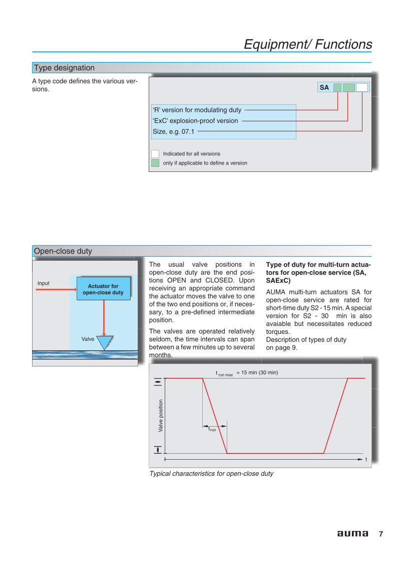
A type code defines the various ver-sions. SA
‘R’ version for modulating duty
Size, e.g. 07.1
‘ExC’ explosion-proof version
Indicated for all versions
only if applicable to define a version
Open-close duty
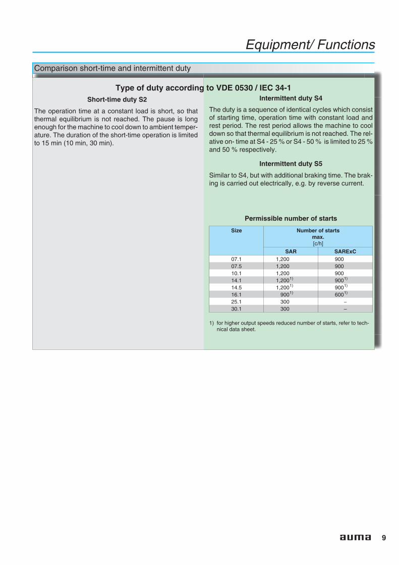
The usual valve positions inopen-close duty are the end posi-tions OPEN and CLOSED. Uponreceiving an appropriate commandthe actuator moves the valve to oneof the two end positions or, if neces-sary, to a pre-defined intermediateposition.
The valves are operated relativelyseldom, the time intervals can spanbetween a few minutes up to severalmonths.
t run max = 15 min (30 min)
trunVal
vepo
sitio
n
t
Typical characteristics for open-close duty
Input
Valve
Actuator foropen-close duty
Type of duty for multi-turn actua-tors for open-close service (SA,SAExC)
AUMA multi-turn actuators SA foropen-close service are rated forshort-time duty S2 - 15 min. A specialversion for S2 - 30 min is alsoavaiable but necessitates reducedtorques.Description of types of dutyon page 9.

8
Equipment/ Functions
Modulating duty
The controlled variable in a modulat-ing application is affected by manyinfluences. A change of the refer-ence input signal, pressure fluctua-tion in the pipeline and temperaturevariations influence the process insuch a way that a frequent adjust-ment of the MOV is required. Forsensitive modulating applicationsthe starts may be in intervals of a fewseconds.
Therefore high demands are placedon actuators for this duty. Mechani-cal components and the motor mustbe designed appropriately to with-stand a large number of operationswith no decline in the required modu-lating accuracy.
Input signal fromprocess controller
Feedback signalto process controller
Transmitter(Sensor)
Valve
Valve position feedback
Controlled variable
Actuatorfor
modulatingduty
Positioner
t
Val
vepo
sitio
n
Types of duty for multi-turn actu-ators for modulating service(SAR, SARExC)
AUMA multi-turn actuators SAR formodulating service are rated forintermittent duty S4 - 25 %. Specialversions for S4 - 50 % and S5 - 25 %are also available.
Typical operation process in modulating duty
Comparison short-time and intermittent duty
Type of duty according to VDE 0530 / IEC 34-1Short-time duty S2
The operation time at a constant load is short, so thatthermal equilibrium is not reached. The pause is longenough for the machine to cool down to ambient temper-ature. The duration of the short-time operation is limitedto 15 min (10 min, 30 min).
Intermittent duty S4
The duty is a sequence of identical cycles which consistof starting time, operation time with constant load andrest period. The rest period allows the machine to cooldown so that thermal equilibrium is not reached. The rel-ative on- time at S4 - 25 % or S4 - 50 % is limited to 25 %and 50 % respectively.
Intermittent duty S5
Similar to S4, but with additional braking time. The brak-ing is carried out electrically, e.g. by reverse current.
Permissible number of starts
Size Number of startsmax.[c/h]
SAR SARExC07.1 1,200 90007.5 1,200 90010.1 1,200 90014.1 1,2001) 9001)
14.5 1,2001) 9001)
16.1 9001) 6001)
25.1 300 –30.1 300 –
1) for higher output speeds reduced number of starts, refer to tech-nical data sheet.
9
Equipment/ Functions
10
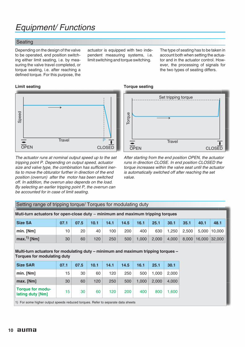
Seating
Depending on the design of the valveto be operated, end position switch-ing either limit seating, i.e. by mea-suring the valve travel completed, ortorque seating, i.e. after reaching adefined torque. For this purpose, the
actuator is equipped with two inde-pendent measuring systems, i.e.limit switching and torque switching.
The type of seating has to be taken inaccount both when setting the actua-tor and in the actuator control. How-ever, the processing of signals forthe two types of seating differs.
Equipment/ Functions
Limit seating
The actuator runs at nominal output speed up to the settripping point P. Depending on output speed, actuatorsize and valve type, the combination has sufficient iner-tia to move the obturator further in direction of the endposition (overrun) after the motor has been switchedoff. In addition, the overrun also depends on the load.By selecting an earlier tripping point P, the overrun canbe accounted for in case of limit seating.
Torque seating
After starting from the end position OPEN, the actuatorruns in direction CLOSE. In end position CLOSED thetorque increases within the valve seat until the actuatoris automatically switched off after reaching the setvalue.
Setting range of tripping torque/ Torques for modulating duty
Travel
Spe
ed
P
CLOSEDOPEN
Muti-turn actuators for open-close duty – minimum and maximum tripping torques
Size SA 07.1 07.5 10.1 14.1 14.5 16.1 25.1 30.1 35.1 40.1 48.1
min. [Nm] 10 20 40 100 200 400 630 1,250 2,500 5,000 10,000
max.1) [Nm] 30 60 120 250 500 1,000 2,000 4,000 8,000 16,000 32,000
Multi-turn actuators for modulating duty – minimum and maximum tripping torques –Torques for modulating duty
Size SAR 07.1 07.5 10.1 14.1 14.5 16.1 25.1 30.1
min. [Nm] 15 30 60 120 250 500 1,000 2,000
max. [Nm] 30 60 120 250 500 1,000 2,000 4,000
Torque for modu-lating duty [Nm]
15 30 60 120 200 400 800 1,600
1) For some higher output speeds reduced torques. Refer to separate data sheets
CLOSEDOPEN
Travel
Set tripping torque
Torq
ue
11
Equipment/ Functions
Overload protection against torque peaks
The torque switching, used fortorque seating in the end position(see page 10), serves as overloadprotection for the entire travel, evenin the case of limit seating.
If excessive torque builds up in thevalve in an intermediate position,e.g. due to a trapped object, thetorque switching trips after reachingthe set tripping torque.
After the controls have processedthe torque switch signal accordingly,the motor will be switched off. As aresult, valve and actuator are pro-tected from damage.
If the limit switch signals are pro-cessed accordingly in the controls,you can distinguish between a nor-mal torque switch tripping at the endpositions and tripping in an interme-
diate position (fault) caused byover-torque.
CLOSEDOPEN
Travel
Set tripping torque
Torq
ue
DUO limit switching/ intermediate position switches (option)
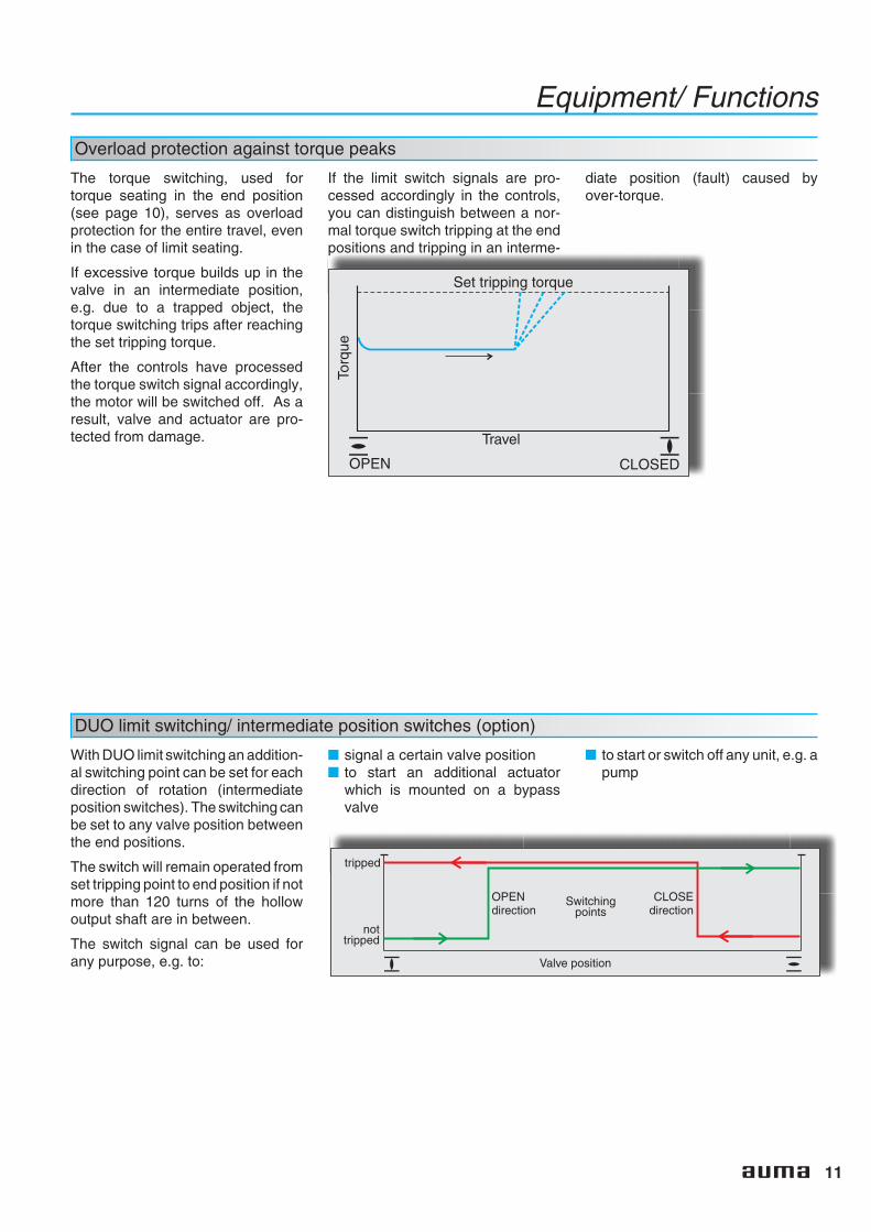
With DUO limit switching an addition-al switching point can be set for eachdirection of rotation (intermediateposition switches). The switching canbe set to any valve position betweenthe end positions.
The switch will remain operated fromset tripping point to end position if notmore than 120 turns of the hollowoutput shaft are in between.
The switch signal can be used forany purpose, e.g. to:
■ signal a certain valve position■ to start an additional actuator
which is mounted on a bypassvalve
■ to start or switch off any unit, e.g. apump
tripped
Switchingpoints
OPENdirection
CLOSEdirection
Valve position
nottripped
12
Equipment/ Functions
Limit and torque switches
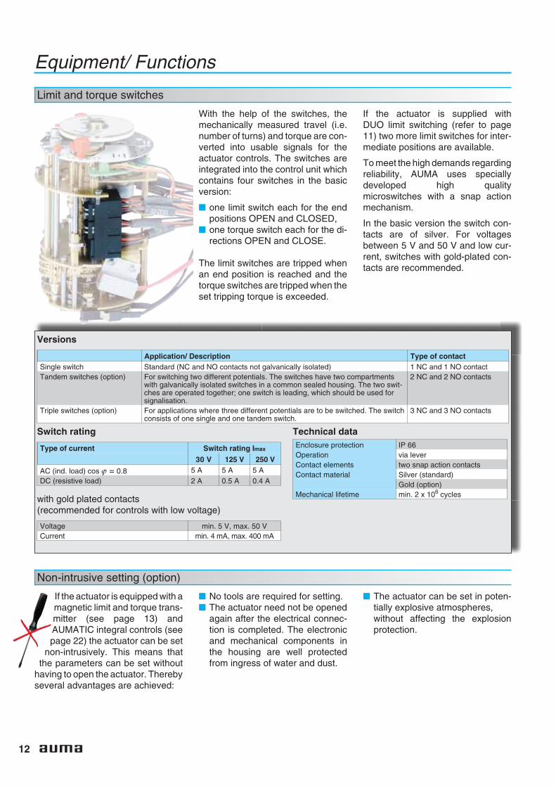
With the help of the switches, themechanically measured travel (i.e.number of turns) and torque are con-verted into usable signals for theactuator controls. The switches areintegrated into the control unit whichcontains four switches in the basicversion:
■ one limit switch each for the endpositions OPEN and CLOSED,
■ one torque switch each for the di-rections OPEN and CLOSE.
The limit switches are tripped whenan end position is reached and thetorque switches are tripped when theset tripping torque is exceeded.
If the actuator is supplied withDUO limit switching (refer to page11) two more limit switches for inter-mediate positions are available.
To meet the high demands regardingreliability, AUMA uses speciallydeveloped high qualitymicroswitches with a snap actionmechanism.
In the basic version the switch con-tacts are of silver. For voltagesbetween 5 V and 50 V and low cur-rent, switches with gold-plated con-tacts are recommended.
Versions
Application/ Description Type of contactSingle switch Standard (NC and NO contacts not galvanically isolated) 1 NC and 1 NO contactTandem switches (option) For switching two different potentials. The switches have two compartments
with galvanically isolated switches in a common sealed housing. The two swit-ches are operated together; one switch is leading, which should be used forsignalisation.
2 NC and 2 NO contacts
Triple switches (option) For applications where three different potentials are to be switched. The switchconsists of one single and one tandem switch.
3 NC and 3 NO contacts
Switch rating
Type of current Switch rating Imax
30 V 125 V 250 V
AC (ind. load) cos ϕ = 0.8 5 A 5 A 5 ADC (resistive load) 2 A 0.5 A 0.4 A
with gold plated contacts(recommended for controls with low voltage)
Voltage min. 5 V, max. 50 VCurrent min. 4 mA, max. 400 mA
Technical dataEnclosure protection IP 66Operation via leverContact elements two snap action contactsContact material Silver (standard)
Gold (option)Mechanical lifetime min. 2 x 10⁶ cycles
Non-intrusive setting (option)
If the actuator is equipped with amagnetic limit and torque trans-mitter (see page 13) andAUMATIC integral controls (seepage 22) the actuator can be set
non-intrusively. This means thatthe parameters can be set without
having to open the actuator. Therebyseveral advantages are achieved:
■ No tools are required for setting.■ The actuator need not be opened
again after the electrical connec-tion is completed. The electronicand mechanical components inthe housing are well protectedfrom ingress of water and dust.
■ The actuator can be set in poten-tially explosive atmospheres,without affecting the explosionprotection.
13
Equipment/ Functions
Magnetic limit and torque transmitter (MWG) (option)
The magnetic limit and torque trans-mitter converts the mechanical val-ues of limit and torque into continu-ous electronic signals.
The simultaneous use of AUMATICintegral controls which evaluate thesignals is a prerequisite for the use ofthe MWG. This variant does not
require any switches for limit posi-tions or torque.
Actuators with MWG have the follow-ing advantages.
■ Non-intrusive setting is possible(see page 12)
■ A torque signal is permanentlyavailable. It can be used forswitching off at the set trippingtorque. It can also be transmittedfor external use, for example fortorque monitoring at the valve.
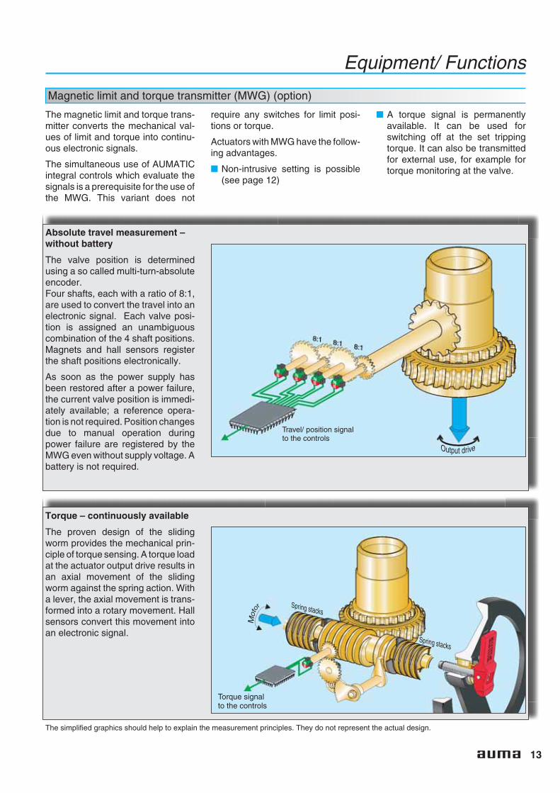
Absolute travel measurement –without battery
The valve position is determinedusing a so called multi-turn-absoluteencoder.Four shafts, each with a ratio of 8:1,are used to convert the travel into anelectronic signal. Each valve posi-tion is assigned an unambiguouscombination of the 4 shaft positions.Magnets and hall sensors registerthe shaft positions electronically.
As soon as the power supply hasbeen restored after a power failure,the current valve position is immedi-ately available; a reference opera-tion is not required. Position changesdue to manual operation duringpower failure are registered by theMWG even without supply voltage. Abattery is not required.
Torque – continuously available
The proven design of the slidingworm provides the mechanical prin-ciple of torque sensing. A torque loadat the actuator output drive results inan axial movement of the slidingworm against the spring action. Witha lever, the axial movement is trans-formed into a rotary movement. Hallsensors convert this movement intoan electronic signal.
Travel/ position signalto the controls
Torque signalto the controls
The simplified graphics should help to explain the measurement principles. They do not represent the actual design.
14
Equipment/ Functions
Position/ torque feedback signal (option)
If the actuator is equipped with anMWG and AUMATIC integral con-trols, the valve position and therequired torque at the valve areavailable as output signals. Even ifthere is no MWG installed in the actu-ator, the position of the valve can betransmitted as a continuous signalfor remote position indication.
Position feedback is provided as ananalogue feedback signal by:
■ Precision potentiometer■ Electronic position transmitter
RWG.
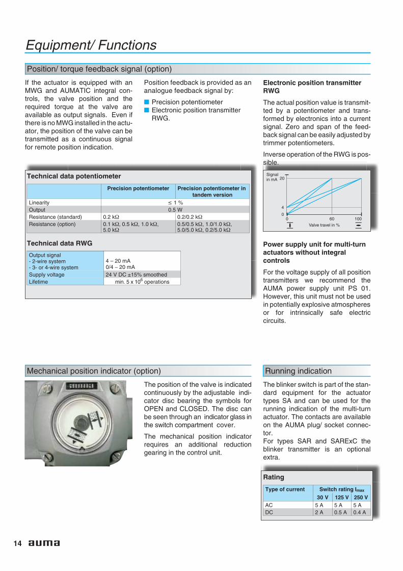
Electronic position transmitterRWG
The actual position value is transmit-ted by a potentiometer and trans-formed by electronics into a currentsignal. Zero and span of the feed-back signal can be easily adjusted bytrimmer potentiometers.
Inverse operation of the RWG is pos-sible.
Technical data potentiometer
Precision potentiometer Precision potentiometer intandem version
Linearity ≤ 1 %Output 0.5 WResistance (standard) 0.2 kΩ 0.2/0.2 kΩResistance (option) 0.1 kΩ, 0.5 kΩ, 1.0 kΩ,
5.0 kΩ0.5/0.5 kΩ, 1.0/1.0 kΩ,5.0/5.0 kΩ, 0.2/5.0 kΩ
Technical data RWG
Output signal- 2-wire system- 3- or 4-wire system
4 – 20 mA0/4 − 20 mA
Supply voltage 24 V DC ±15% smoothedLifetime min. 5 x 10⁶ operations
Power supply unit for multi-turnactuators without integralcontrols
For the voltage supply of all positiontransmitters we recommend theAUMA power supply unit PS 01.However, this unit must not be usedin potentially explosive atmospheresor for intrinsically safe electriccircuits.
1006000
20Signalin mA
4
Valve travel in %
Mechanical position indicator (option)
The position of the valve is indicatedcontinuously by the adjustable indi-cator disc bearing the symbols forOPEN and CLOSED. The disc canbe seen through an indicator glass inthe switch compartment cover.
The mechanical position indicatorrequires an additional reductiongearing in the control unit.
Running indication
The blinker switch is part of the stan-dard equipment for the actuatortypes SA and can be used for therunning indication of the multi-turnactuator. The contacts are availableon the AUMA plug/ socket connec-tor.For types SAR and SARExC theblinker transmitter is an optionalextra.
Rating
Type of current Switch rating Imax
30 V 125 V 250 VAC 5 A 5 A 5 ADC 2 A 0.5 A 0.4 A
15
Equipment/ Functions
Heater
Heater in switch compartment(standard)
Condensation in the actuator is pos-sible due to wide fluctuation of theambient temperature. The heaterintegrated in the control unit pre-vents this in general.
The heater is rated for continuousduty. Therefore it should always beenergized, but at the very least whenthe actuator is not operating.
Technical data for heater in switch compartment
Heater for actuatorswithout integral controls
Heater for actuators withintegral controls
Heating element self-regulating PTC element Resistance type heaterVoltage ranges 110 V – 250 V DC/AC
24 V – 48 V DC/AC380 V – 400 V AC
24 V DC/AC (internal supply)
Output 5 W – 20 W 5 W
Motor heater(option)
For operation in extremely low tem-peratures AUMA strongly recom-mends the use of a motor heater.This applies to actuators in extremelow temperature version from– 50 °C. The heater prevents actua-tor starting problems caused byextremely cold temperatures.
Locking device for manual operation (option)
The locking device prevents un-authorized manual operation of themulti-turn actuator.
Wiring diagrams
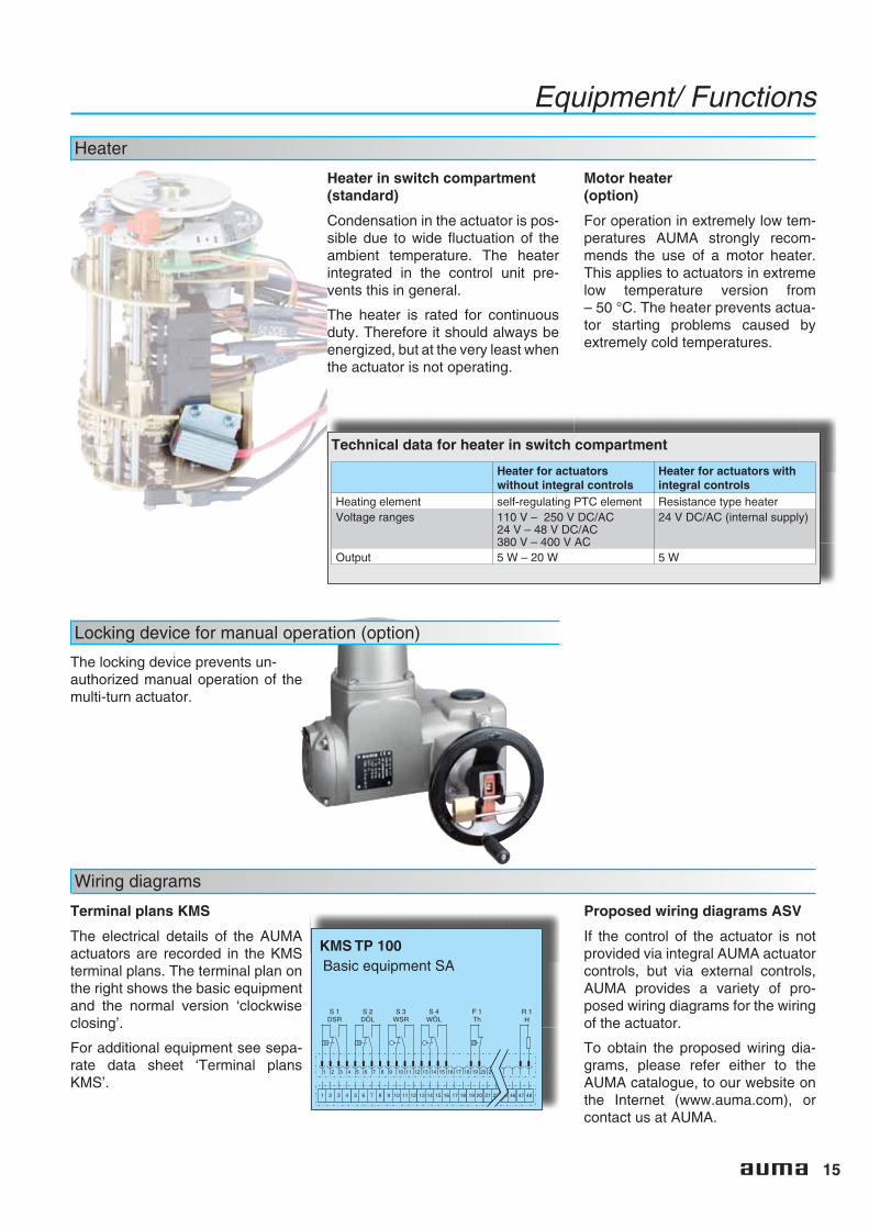
Terminal plans KMS
The electrical details of the AUMAactuators are recorded in the KMSterminal plans. The terminal plan onthe right shows the basic equipmentand the normal version ‘clockwiseclosing’.
For additional equipment see sepa-rate data sheet ‘Terminal plansKMS’.
KMS TP 100
R 1H
Basic equipment SA
Proposed wiring diagrams ASV
If the control of the actuator is notprovided via integral AUMA actuatorcontrols, but via external controls,AUMA provides a variety of pro-posed wiring diagrams for the wiringof the actuator.
To obtain the proposed wiring dia-grams, please refer either to theAUMA catalogue, to our website onthe Internet (www.auma.com), orcontact us at AUMA.
16
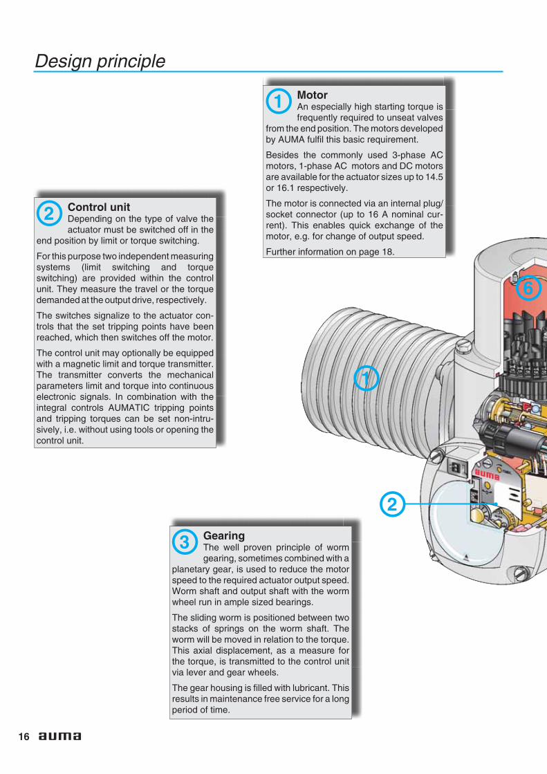
Design principle
MotorAn especially high starting torque isfrequently required to unseat valves
from the end position. The motors developedby AUMA fulfil this basic requirement.
Besides the commonly used 3-phase ACmotors, 1-phase AC motors and DC motorsare available for the actuator sizes up to 14.5or 16.1 respectively.
The motor is connected via an internal plug/socket connector (up to 16 A nominal cur-rent). This enables quick exchange of themotor, e.g. for change of output speed.
Further information on page 18.
Control unitDepending on the type of valve theactuator must be switched off in the
end position by limit or torque switching.
For this purpose two independent measuringsystems (limit switching and torqueswitching) are provided within the controlunit. They measure the travel or the torquedemanded at the output drive, respectively.
The switches signalize to the actuator con-trols that the set tripping points have beenreached, which then switches off the motor.
The control unit may optionally be equippedwith a magnetic limit and torque transmitter.The transmitter converts the mechanicalparameters limit and torque into continuouselectronic signals. In combination with theintegral controls AUMATIC tripping pointsand tripping torques can be set non-intru-sively, i.e. without using tools or opening thecontrol unit.
GearingThe well proven principle of wormgearing, sometimes combined with a
planetary gear, is used to reduce the motorspeed to the required actuator output speed.Worm shaft and output shaft with the wormwheel run in ample sized bearings.
The sliding worm is positioned between twostacks of springs on the worm shaft. Theworm will be moved in relation to the torque.This axial displacement, as a measure forthe torque, is transmitted to the control unitvia lever and gear wheels.
The gear housing is filled with lubricant. Thisresults in maintenance free service for a longperiod of time.
1
2
3
1
2
6

17
Design principle
Valve attachmentThe mounting flange is according toEN ISO 5210 or DIN 3210.
Various output drive types are available.Therefore it is possible to adapt to differenttypes of valves.
Further information on page 26.
Manual operationFor commissioning or in an emer-gency, the multi-turn actuator can be
operated with the handwheel. By operatingthe red change-over lever the motor drive isdisconnected and the manual driveengaged. Since disconnection betweenmotor and drive shaft is made before theself-locking worm/ worm wheel, easychange over to manual drive is possible evenif the actuator has been operated at full ratedtorque.
When starting the motor the manual drive isautomatically disengaged. During electricoperation the handwheel does not rotate.
Electrical connectionThe connection for motor and con-trols up to size 16.1 are made on a
50-pole AUMA plug/ socket connector. Onlarger sizes, the motor is connected to termi-nals in the actuator.
If the plug/ socket is disconnected for mainte-nance work, the wiring remains undisturbed.
The explosion-proof actuator types SAExCand SARExC are provided with a specialplug/ socket connector for explosion-proofactuators as a standard.
Further information on page 24.
4
5
6
3
4
5

18
Equipment/ Functions
Motors
3-phase AC motors
As a standard, AUMA actuators areequipped with 3-phase AC motors(TENV, pot-type motor without venti-lation).
AUMA has developed these motorsto comply with the special require-ments in valve automation. The mostsignificant features of this construc-tion are the high starting torque, thelow flywheel effect and the thermalmotor protection.
Technical data
3-phase AC motor 1-phase AC motor DC motor
Standard voltages 50 Hz:220 V; 230 V; 240 V380 V;400 V; 415 V;500 V
60 Hz:440 V; 460 V; 480 V
50 Hz: 220 V – 240 V60 Hz: 110 V – 120 V
220 V; 110 V; 60 V; 48 V;24 V
Permissible variations ± 10 %1) ± 10 %1) ± 10 %1)
Motor data Refer to data sheets
Design/ mounting IM B9 acc. to IEC 34-7 IM B14 according to IEC 34-7
Type of motor Squirrel cage Squirrel cage DC rotor
Enclosure protection IP 67IP 68 (option)
IP 65 – IP 68 IP 55IP 67/ 68 (option)
Type of cooling Self-cooling/ surface cooling (IC 40 according to IEC 34-6)
Insulation class F according to IEC 85, tropicalised
Electrical connectionfor motor
up to SA 16.1 (up to 7.5 kW):AUMA plug/ socket connectorat multi-turn actuatorSA 25.1 and larger: Terminalsat multi-turn actuator
AUMA plug/ socket connec-tor at multi-turn actuator
Motor terminal box
Starting direct on line
Type of duty S2 - 15 min, S2 - 30 min, S4 -25 %, S4 - 50 % or S5,
S2 - 10 min orS4 - 25 %
S2 - 15 min
Direction of rotation clockwise and counter-clockwise (reversing)
Motor protection 3 thermoswitches or3 PTC thermistors
2 thermoswitches -
1) Overvoltage may result in excessive temperature rise in the motor windings. In the case of under voltage the motor torque (stall torque)decreases in the ratio of the square of undervoltage divided by the standard voltage. Larger undervoltage variations have therefore to beconsidered when sizing the actuator.
AUMA special motor withhigh starting torque
Tor
que
T
Output speed n
Standard motor with thesame power
Special motors
On request, and if technically feasi-ble, two-speed and brake motorscan be used.
DC motor
AUMA multi-turn actuators are alsoavailable with DC motors.
Note: In some cases starting resis-tors may be required (refer to sepa-rate data sheet). Those are not partof the AUMA supply.
1-phase AC motor
AUMA multi-turn actuators SA 07.1 –SA 14.5 can be supplied as an optionwith 1-phase AC motor. The requiredcapacitor and the sometimes neces-sary starting switch are fitted in anenlarged plug cover.
19
Motor protection
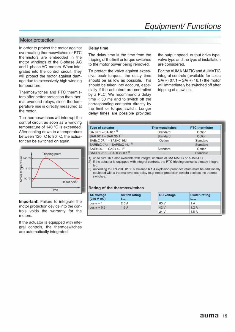
In order to protect the motor againstoverheating thermoswitches or PTCthermistors are embedded in themotor windings of the 3-phase ACand 1-phase AC motors. When inte-grated into the control circuit, theywill protect the motor against dam-age due to excessively high windingtemperature.
Thermoswitches and PTC thermis-tors offer better protection than ther-mal overload relays, since the tem-perature rise is directly measured atthe motor.
The thermoswitches will interrupt thecontrol circuit as soon as a windingtemperature of 140 °C is exceeded.After cooling down to a temperaturebetween 120 °C to 90 °C, the actua-tor can be switched on again.
Important! Failure to integrate themotor protection device into the con-trols voids the warranty for themotors.
If the actuator is equipped with inte-gral controls, the thermoswitchesare automatically integrated.
Equipment/ Functions
Delay time
The delay time is the time from thetripping of the limit or torque switchesto the motor power being removed.
To protect the valve against exces-sive peak torques, the delay timeshould be as low as possible. Thisshould be taken into account, espe-cially if the actuators are controlledby a PLC. We recommend a delaytime < 50 ms and to switch off thecorresponding contactor directly bythe limit or torque switch. Longerdelay times are possible provided
the output speed, output drive type,valve type and the type of installationare considered.
For the AUMA MATIC and AUMATICintegral controls (available for sizesSA(R) 07.1 – SA(R) 16.1) the motorwill immediately be switched off aftertripping of a switch.
Type of actuator Thermoswitches PTC thermistorSA 07.1 – SA 48.11) Standard OptionSAR 07.1 – SAR 30.11) Standard OptionSAExC 07.1 – SAExC 16.1 Option StandardSARExC 07.1 – SARExC 16.12) – StandardSAEx 25.1 – SAEx 40.13) Standard OptionSAREx 25.1 – SAREx 30.13) – Standard
1) up to size 16.1 also available with integral controls AUMA MATIC or AUMATIC2) If the actuator is equipped with integral controls, the PTC tripping device is already integra-
ted.3) According to DIN VDE 0165 subclause 6.1.4 explosion-proof actuators must be additionally
equipped with a thermal overload relay (e.g. motor protection switch) besides the thermo-switches.
Rating of the thermoswitches
AC voltage(250 V AC)
Switch ratingImax
cos ϕ = 1 2.5 Acos ϕ = 0.6 1.6 A
DC voltage Switch ratingImax
60 V 1 A42 V 1.2 A24 V 1.5 A
140 °C
90 °C
115 °C
Mot
orte
mpe
ratu
re
Tripping point
Time
Reset point
20
Output speeds
Output speeds
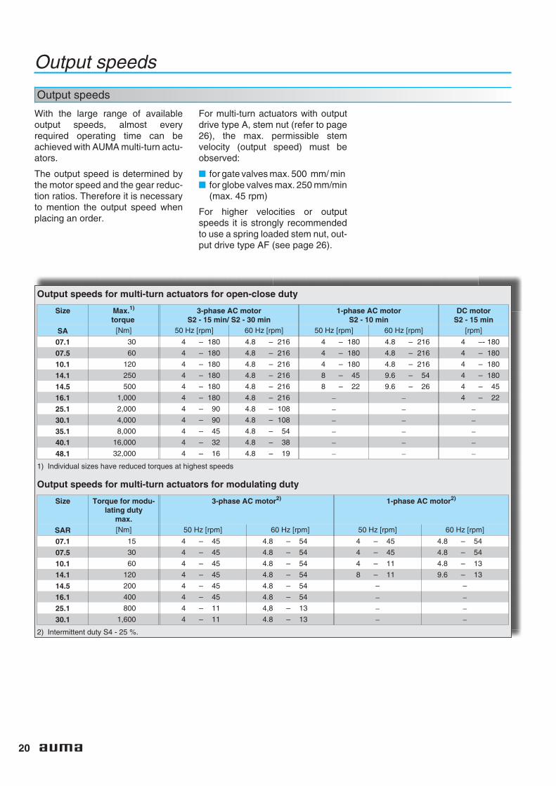
With the large range of availableoutput speeds, almost everyrequired operating time can beachieved with AUMA multi-turn actu-ators.
The output speed is determined bythe motor speed and the gear reduc-tion ratios. Therefore it is necessaryto mention the output speed whenplacing an order.
For multi-turn actuators with outputdrive type A, stem nut (refer to page26), the max. permissible stemvelocity (output speed) must beobserved:
■ for gate valves max. 500 mm/ min■ for globe valves max. 250 mm/min
(max. 45 rpm)
For higher velocities or outputspeeds it is strongly recommendedto use a spring loaded stem nut, out-put drive type AF (see page 26).
Output speeds for multi-turn actuators for open-close duty
Size Max.1)
torque3-phase AC motor
S2 - 15 min/ S2 - 30 min1-phase AC motor
S2 - 10 minDC motor
S2 - 15 min
SA [Nm] 50 Hz [rpm] 60 Hz [rpm] 50 Hz [rpm] 60 Hz [rpm] [rpm]
07.1 30 4 – 180 4.8 – 216 4 – 180 4.8 – 216 4 –- 180
07.5 60 4 – 180 4.8 – 216 4 – 180 4.8 – 216 4 – 180
10.1 120 4 – 180 4.8 – 216 4 – 180 4.8 – 216 4 – 180
14.1 250 4 – 180 4.8 – 216 8 – 45 9.6 – 54 4 – 180
14.5 500 4 – 180 4.8 – 216 8 – 22 9.6 – 26 4 – 45
16.1 1,000 4 – 180 4.8 – 216 − − 4 – 22
25.1 2,000 4 – 90 4.8 – 108 − − −30.1 4,000 4 – 90 4.8 – 108 − − −35.1 8,000 4 – 45 4.8 – 54 − − −40.1 16,000 4 – 32 4.8 – 38 − − −48.1 32,000 4 – 16 4.8 – 19 − − −
1) Individual sizes have reduced torques at highest speeds
Output speeds for multi-turn actuators for modulating duty
Size Torque for modu-lating duty
max.
3-phase AC motor2) 1-phase AC motor2)
SAR [Nm] 50 Hz [rpm] 60 Hz [rpm] 50 Hz [rpm] 60 Hz [rpm]
07.1 15 4 – 45 4.8 – 54 4 – 45 4.8 – 54
07.5 30 4 – 45 4.8 – 54 4 – 45 4.8 – 54
10.1 60 4 – 45 4.8 – 54 4 – 11 4.8 – 13
14.1 120 4 – 45 4.8 – 54 8 – 11 9.6 – 13
14.5 200 4 – 45 4.8 – 54 – –
16.1 400 4 – 45 4.8 – 54 − −25.1 800 4 – 11 4,8 – 13 − −30.1 1,600 4 – 11 4.8 – 13 − −
2) Intermittent duty S4 - 25 %.
21
Actuator controls
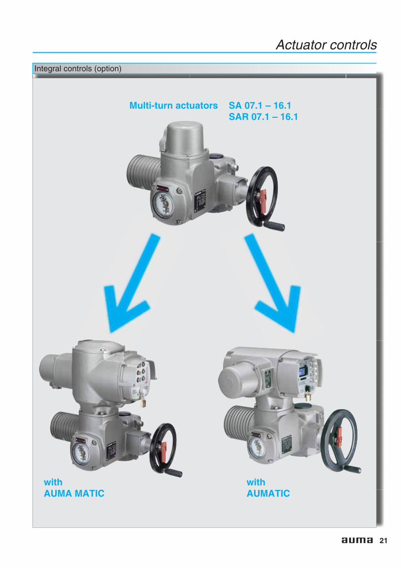
Integral controls (option)
Multi-turn actuators SA 07.1 – 16.1SAR 07.1 – 16.1
withAUMA MATIC
withAUMATIC

22
Actuator controls
Which type of controls?
AUMA MATIC
The AUMA MATIC is the idealcontrol for open-close
duty. Functionssuch as the auto-matic phasecorrection sim-plifycommisioning.To operate the
actuator on site theintegral local con-trols can be used.
The following feedback signals areavailable: end positions reached,tripping torque exceeded, the selec-tor switch position and a collectivefault signal.
An explosion-proof version of theAUMA MATIC is available.
AUMATIC
The AUMATIC withmicrocontroller includesall functions of theAUMA MATIC. In addi-tion, the AUMATIC hasa variety of additionalfunctions and the equip-ment has been consid-erably expanded:
■ Non-intrusive setting(option)
■ Adaptive positioner (option)■ Programmable signal relays■ Fieldbus interface (option)
■ Display with plain text display■ Monitoring and diagnosis■ Logging of operating data■ Serial programming interface1)
The AUMATIC design: A modularsystem consisting of functions, com-munication interfaces and equip-ment elements, enables the combi-nation of the ideal solution for everyvalve automation problem.
An explosion-proof version of theAUMATIC is available.
1) Please note, due to patent law the AUMATIC product with infrared interface on local controls must not be supplied to either the UK or Japan.This product without infrared interface does not infringe a patent and can be supplied to either country.
Wall bracket
The controls, also in explosion-proofversion, can be mounted separatelyfrom the actuator on a wall bracket(see page 5). This is recommendedif:
■ limited space would restrict theaccess to directly mounted con-trols
■ high ambient temperatures in thesurroundings of the actuator couldaffect the electronics,
■ heavy vibrations of the valve couldinfluence the controls.
Further literature
Detailed information can be found inthe following brochures:
■ Product descriptionActuator controls AUMATIC
■ Product descriptionActuator controls AUMA MATIC
23
Actuator controls
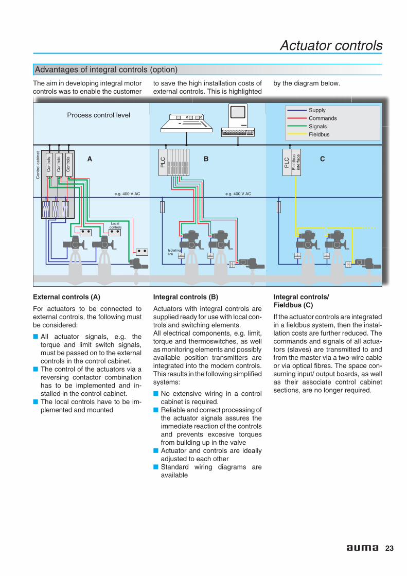
Advantages of integral controls (option)
The aim in developing integral motorcontrols was to enable the customer
to save the high installation costs ofexternal controls. This is highlighted
by the diagram below.
External controls (A)
For actuators to be connected toexternal controls, the following mustbe considered:
■ All actuator signals, e.g. thetorque and limit switch signals,must be passed on to the externalcontrols in the control cabinet.
■ The control of the actuators via areversing contactor combinationhas to be implemented and in-stalled in the control cabinet.
■ The local controls have to be im-plemented and mounted
A B C
Con
trol
cabi
net
Con
trol
s
Process control level
e.g. 400 V AC e.g. 400 V AC
Localcontrols
Isolatinglink
Supply
Commands
Signals
Fieldbus
PLC
PLC
Fie
ldbu
sin
terf
ace
Con
trol
s
Con
trol
s
Integral controls (B)
Actuators with integral controls aresupplied ready for use with local con-trols and switching elements.All electrical components, e.g. limit,torque and thermoswitches, as wellas monitoring elements and possiblyavailable position transmitters areintegrated into the modern controls.This results in the following simplifiedsystems:
■ No extensive wiring in a controlcabinet is required.
■ Reliable and correct processing ofthe actuator signals assures theimmediate reaction of the controlsand prevents excesive torquesfrom building up in the valve
■ Actuator and controls are ideallyadjusted to each other
■ Standard wiring diagrams areavailable
Integral controls/Fieldbus (C)
If the actuator controls are integratedin a fieldbus system, then the instal-lation costs are further reduced. Thecommands and signals of all actua-tors (slaves) are transmitted to andfrom the master via a two-wire cableor via optical fibres. The space con-suming input/ output boards, as wellas their associate control cabinetsections, are no longer required.

24
Interfaces
Electrical connection
AUMA plug/ socket connector
Multi-turn actuators SA and SAR upto size 16.1 are equipped with AUMAplug/ socket connector for motor andcontrols. This applies whether theactuator is equipped with integralcontrols or not.
The significant advantage of thistype of connection:Once connected, the wiring remainsundisturbed, even if the actuator has
to be removed from the valve, e.g. formaintenance purposes.
For size SA 25.1 and larger the motoris connected to screw type terminalsin the terminal compartment of theactuator. The controls will still bewired to the AUMA plug/socketconnector.
Double sealed(option) The double sealed connection is a
sealed plug and socket which is fittedbetween the actuator housing andthe plug/ socket connector. Evenafter removing the plug cover or if thecable glands do not seal properly thedevice will be protected against theingress of dust or humidity.
Plug/ socket connector with terminal board for explosion-proof multi-turn actuators SAExC and SARExC
Explosion-proof actuators in ver-sions with or without controls aredesigned with a ‘flameproof enclo-sure’. The sealed terminal board ofthis electrical connection ensuresthat the flameproof enclosureremains undisturbed even if the plugcover has been removed.
The electrical connection betweenthe terminal board and the electric/electronic components within theactuator provided via a plug/ socketconnector. The advantage of themodular design with plug-in connec-
tion is thereby also provided forexplosion-proof actuators.
The customer connection compart-ment is designated protection type‘increased safety’.
By means of a protection cover,which is available as an option, thedisconnected plug may be fitted to awall to enable the operation of theplant under explosion-proof condi-tions.
Plug-in terminal connection for explosion-proof multi-turn actuators SAExC and SARExC (option)
Contrary to the plug/ socketconnector, the customer connectionis made on terminals which havebeen fitted to a terminal frame. Theconnection compartment has beenenlarged. In terms of explosion pro-tection this connection type has thesame characteristics as the plug/socket connector.
On request, these terminals can alsobe used for non-explosion-proofactuators.
By means of a protection coverwhich is available as an option, thedisconnected plug may be fitted to awall to enable the operation of theplant under explosion-proof condi-tions.
25
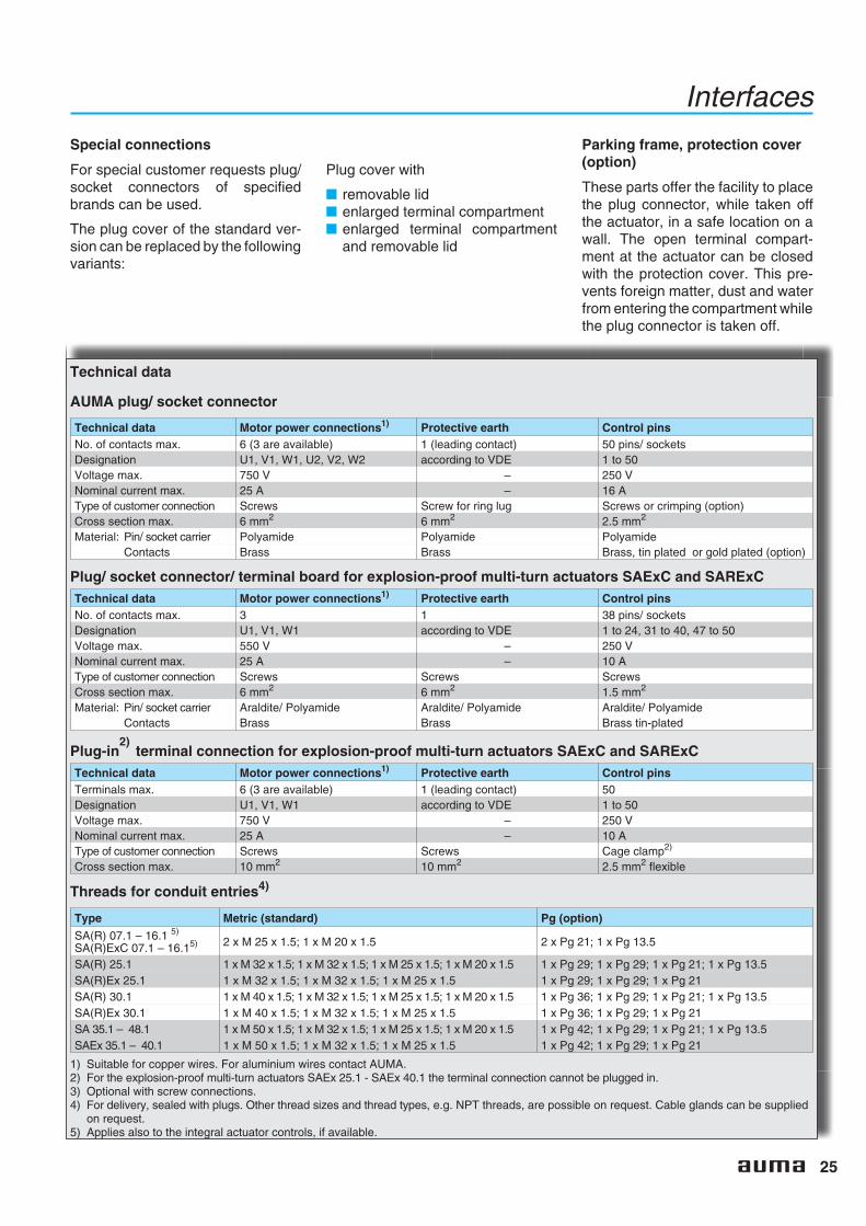
Special connections
For special customer requests plug/socket connectors of specifiedbrands can be used.
The plug cover of the standard ver-sion can be replaced by the followingvariants:
Plug cover with
■ removable lid■ enlarged terminal compartment■ enlarged terminal compartment
and removable lid
Interfaces
Technical data
AUMA plug/ socket connector
Technical data Motor power connections1) Protective earth Control pinsNo. of contacts max. 6 (3 are available) 1 (leading contact) 50 pins/ socketsDesignation U1, V1, W1, U2, V2, W2 according to VDE 1 to 50Voltage max. 750 V – 250 VNominal current max. 25 A – 16 AType of customer connection Screws Screw for ring lug Screws or crimping (option)Cross section max. 6 mm2 6 mm2 2.5 mm2
Material: Pin/ socket carrier Polyamide Polyamide PolyamideContacts Brass Brass Brass, tin plated or gold plated (option)
Plug/ socket connector/ terminal board for explosion-proof multi-turn actuators SAExC and SARExCTechnical data Motor power connections1) Protective earth Control pinsNo. of contacts max. 3 1 38 pins/ socketsDesignation U1, V1, W1 according to VDE 1 to 24, 31 to 40, 47 to 50Voltage max. 550 V – 250 VNominal current max. 25 A – 10 AType of customer connection Screws Screws ScrewsCross section max. 6 mm2 6 mm2 1.5 mm2
Material: Pin/ socket carrier Araldite/ Polyamide Araldite/ Polyamide Araldite/ PolyamideContacts Brass Brass Brass tin-plated
Plug-in terminal connection for explosion-proof multi-turn actuators SAExC and SARExCTechnical data Motor power connections1) Protective earth Control pinsTerminals max. 6 (3 are available) 1 (leading contact) 50Designation U1, V1, W1 according to VDE 1 to 50Voltage max. 750 V – 250 VNominal current max. 25 A – 10 AType of customer connection Screws Screws Cage clamp2)
Cross section max. 10 mm2 10 mm2 2.5 mm2 flexible
Threads for conduit entries4)
Type Metric (standard) Pg (option)
SA(R) 07.1 – 16.1 5)
SA(R)ExC 07.1 – 16.15) 2 x M 25 x 1.5; 1 x M 20 x 1.5 2 x Pg 21; 1 x Pg 13.5
SA(R) 25.1 1 x M 32 x 1.5; 1 x M 32 x 1.5; 1 x M 25 x 1.5; 1 x M 20 x 1.5 1 x Pg 29; 1 x Pg 29; 1 x Pg 21; 1 x Pg 13.5SA(R)Ex 25.1 1 x M 32 x 1.5; 1 x M 32 x 1.5; 1 x M 25 x 1.5 1 x Pg 29; 1 x Pg 29; 1 x Pg 21SA(R) 30.1 1 x M 40 x 1.5; 1 x M 32 x 1.5; 1 x M 25 x 1.5; 1 x M 20 x 1.5 1 x Pg 36; 1 x Pg 29; 1 x Pg 21; 1 x Pg 13.5SA(R)Ex 30.1 1 x M 40 x 1.5; 1 x M 32 x 1.5; 1 x M 25 x 1.5 1 x Pg 36; 1 x Pg 29; 1 x Pg 21SA 35.1 – 48.1 1 x M 50 x 1.5; 1 x M 32 x 1.5; 1 x M 25 x 1.5; 1 x M 20 x 1.5 1 x Pg 42; 1 x Pg 29; 1 x Pg 21; 1 x Pg 13.5SAEx 35.1 – 40.1 1 x M 50 x 1.5; 1 x M 32 x 1.5; 1 x M 25 x 1.5 1 x Pg 42; 1 x Pg 29; 1 x Pg 21
1) Suitable for copper wires. For aluminium wires contact AUMA.2) For the explosion-proof multi-turn actuators SAEx 25.1 - SAEx 40.1 the terminal connection cannot be plugged in.3) Optional with screw connections.4) For delivery, sealed with plugs. Other thread sizes and thread types, e.g. NPT threads, are possible on request. Cable glands can be supplied
on request.5) Applies also to the integral actuator controls, if available.
Parking frame, protection cover(option)
These parts offer the facility to placethe plug connector, while taken offthe actuator, in a safe location on awall. The open terminal compart-ment at the actuator can be closedwith the protection cover. This pre-vents foreign matter, dust and waterfrom entering the compartment whilethe plug connector is taken off.
2)

26
Valve attachment
The valve attachment is according toEN ISO 5210 or DIN 3210.
Flange sizes
Size SA/ SAR 07.1 07.5 10.1 14.1 14.5 16.1 25.1 30.1 35.1 40.1 48.1
Torque max. [Nm] 30 60 120 250 500 1,000 2,000 4,000 8,000 16,000 32,000
ISO 5210Standard F07 F07 F10 F14 F14 F16 F25 F30 F35 F40 F48
Option F10 F10 – – – – – – – – –
Output drive types
Various output drive types accordingto EN ISO 5210 or DIN 3210 areavailable in order to adapt themulti-turn actuators to the differenttypes of valves. On request it is pos-sible to supply output drives accord-ing to DIN 3338.
Output drive type A (EN ISO5210/ DIN 3210)
Stem nut forrising andnon-rotatingvalve stems.
The mountingflange togetherwith the stemnut and thrustbearings form one assembly, whichis suitable for accepting thrust.
Output drive type AF(EN ISO 5210/ DIN 3210)
Spring-loadedstem nut fornon-rotating,rising valvestems. Thesprings com-pensate fordynamic thrustat high speedsor even for ther-mal expansionof the valve stem.
Output drive types B1, B2(EN ISO 5210) orB (DIN 3210)
The plug sleeve isintegrated intothe hollow shaftand isdesigned fortransmis-sion oftorque. Lowradial loadscan be accepted.
Output drive types B3 or B4(EN ISO 5210) or E (3210)
Bore withkeyway. Byusing an outputsocket, the out-put drive B1can beconvertedinto typeB3 or B4 orE respectively.
Special output drives
Further output drive types are avail-able besides those described:
■ Pendulum stem nut AK■ Stem nut with plain bearings AG■ Hexagon in hollow shaft■ Insulated output drives IB1 and
IB3
Detailed information on special out-put drive types can be found on sep-arate data sheets and price lists.
Interfaces
27
Service conditions
Enclosure protection
IP 67
AUMA multi-turn actuators conformto enclosure protection IP 67 accord-ing to EN 60 529. IP 67 means pro-tection against immersion up to max.1 m head of water for max. 30 min-utes.
IP 68
AUMA multi-turn actuators are avail-able with improved enclosure pro-tection IP 68 according to EN 60 529.IP 68 means protection against sub-mersion up to 6 m head of water formax. 72 hours. During submersionup to 10 operations are permissible.
In order to guarantee the enclosureprotection IP 68, suitable cableglands have to be used. They are notpart of the standard supply, but canbe provided by AUMA, if ordered.
Corrosion protection/ Colour
KN (standard)
The standard AUMA corrosion pro-tection KN is a high quality coating.This is suitable for outdoor installa-tion and for slightly aggressive atmo-spheres with a low level of pollution.
KS
AUMA recommends this corrosionprotection class when installingdevices in occasionally or perma-nently aggressive atmospheres witha moderate pollutant concentration(e.g. in sewage treatment plants,chemical industry).
KX
AUMA recommends this corrosionprotection class when installingdevices in extremely aggressiveatmospheres with high humidity andhigh pollutant concentration.
Colour
The standard colour of the finishcoating is silver-grey (DB 702, simi-lar to RAL 9007). Other colours arepossible on request.
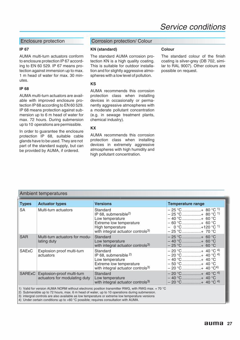
Ambient temperatures
Types Actuator types Versions Temperature range
SA Multi-turn actuators StandardIP 68, submersible2)
Low temperatureExtreme low temperatureHigh temperaturewith integral actuator controls3)
– 25 °C .................+ 80 °C 1)
– 25 °C .................+ 80 °C 1)
– 40 °C .................+ 60 °C– 60 °C .................+ 60 °C– 0 °C .................+120 °C 1)
– 25 °C .................+ 70 °CSAR Multi-turn actuators for modu-
lating dutyStandardLow temperaturewith integral actuator controls3)
– 25 °C .................+ 60 °C– 40 °C .................+ 60 °C– 25 °C .................+ 60 °C
SAExC Explosion proof multi-turnactuators
StandardIP 68, submersible 2)
Low temperatureExtreme low temperaturewith integral actuator controls3)
– 20 °C .................+ 40 °C 4)
– 20 °C .................+ 40 °C 4)
– 40 °C .................+ 40 °C– 50 °C .................+ 40 °C– 20 °C .................+ 40 °C4)
SARExC Explosion-proof multi-turnactuators for modulating duty
StandardLow temperaturewith integral actuator controls3)
– 20 °C .................+ 40 °C 4)
– 40 °C .................+ 40 °C– 20 °C .................+ 40 °C 4)
1) Valid for version AUMA NORM without electronic position transmitter RWG, with RWG max. + 70 °C2) Submersible up to 72 hours, max. 6 m head of water, up to 10 operations during submersion.3) intergral controls are also available as low temperature or extreme low temperature versions4) Under certain conditions up to +60 °C possible; requires consultation with AUMA.
28
Service conditions
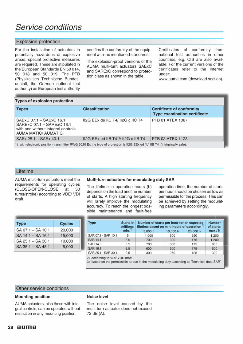
Explosion protection
Types of explosion protection
Types Classification Certificate of conformityType examination certificate
SAExC 07.1 – SAExC 16.1SARExC 07.1 – SARExC 16.1with and without integral controlsAUMA MATIC/ AUMATIC
II2G EEx de IIC T4/ II2G c IIC T4 PTB 01 ATEX 1087
SAEx 25.1 – SAEx 40.1 II2G EEx ed IIB T41)/ II2G c IIB T4 PTB 03 ATEX 11231) with electronic position transmitter RWG 5020 Ex the type of protection is II2G EEx ed [ib] IIB T4 (intrinsically safe).
Lifetime
AUMA multi-turn actuators meet therequirements for operating cycles(CLOSE-OPEN-CLOSE at 30turns/stroke) according to VDE/ VDIdraft.
Type Cycles
SA 07.1 – SA 10.1 20,000SA 14.1 – SA 16.1 15,000SA 25.1 – SA 30.1 10,000SA 35.1 – SA 48.1 5,000
Multi-turn actuators for modulating duty SAR
The lifetime in operation hours (h)depends on the load and the numberof starts. A high starting frequencywill rarely improve the modulatingaccuracy. To reach the longest pos-sible maintenance and fault-free
operation time, the number of startsper hour should be chosen as low aspermissible for the process. This canbe achieved by setting the modulat-ing parameters accordingly.
Type Starts inmillions
min. 2)
Number of starts per hour for an expectedlifetime based on min. hours of operation 3)
Numberof startsmax / h5,000 h 10,000 h 20,000 h
SAR 07.1 - SAR 10.1 5 1,000 500 250 1,200SAR 14.1 3.5 700 300 175 1,200SAR 14.5 3.5 700 300 175 900SAR 16.1 3.5 600 300 175 600SAR 25.1 - SAR 30.1 2.5 300 250 125 300
2) according to VDI/ VDE draft3) based on the permissible torque in the modulating duty according to ‘Technical data SAR’
Other service conditions
Mounting position
AUMA actuators, also those with inte-gral controls, can be operated withoutrestriction in any mounting position.
Noise level
The noise level caused by themulti-turn actuator does not exceed72 dB (A).
For the installation of actuators inpotentially hazardous or explosiveareas, special protective measuresare required. These are stipulated inthe European Standards EN 50 014,50 018 and 50 019. The PTB(Physikalisch Technische Bundes-anstalt, the German national testauthority) as European test authority
certifies the conformity of the equip-ment with the mentioned standards.
The explosion-proof versions of theAUMA multi-turn actuators SAExCand SARExC correspond to protec-tion class as shown in the table.
Certificates of conformity fromnational test authorities in othercountries, e.g. CIS are also avail-able. For the current versions of thecertificates refer to the Internetunder:www.auma.com (download section).
29
Combinations Multi-turn actuators/ Gearboxes
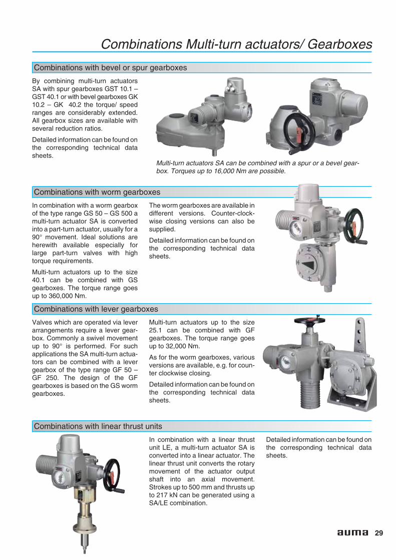
Combinations with bevel or spur gearboxes
By combining multi-turn actuatorsSA with spur gearboxes GST 10.1 –GST 40.1 or with bevel gearboxes GK10.2 – GK 40.2 the torque/ speedranges are considerably extended.All gearbox sizes are available withseveral reduction ratios.
Detailed information can be found onthe corresponding technical datasheets.
Combinations with worm gearboxes
Combinations with lever gearboxes
Multi-turn actuators SA can be combined with a spur or a bevel gear-box. Torques up to 16,000 Nm are possible.
In combination with a worm gearboxof the type range GS 50 – GS 500 amulti-turn actuator SA is convertedinto a part-turn actuator, usually for a90° movement. Ideal solutions areherewith available especially forlarge part-turn valves with hightorque requirements.
Multi-turn actuators up to the size40.1 can be combined with GSgearboxes. The torque range goesup to 360,000 Nm.
The worm gearboxes are available indifferent versions. Counter-clock-wise closing versions can also besupplied.
Detailed information can be found onthe corresponding technical datasheets.
Valves which are operated via leverarrangements require a lever gear-box. Commonly a swivel movementup to 90° is performed. For suchapplications the SA multi-turn actua-tors can be combined with a levergearbox of the type range GF 50 –GF 250. The design of the GFgearboxes is based on the GS wormgearboxes.
Multi-turn actuators up to the size25.1 can be combined with GFgearboxes. The torque range goesup to 32,000 Nm.
As for the worm gearboxes, variousversions are available, e.g. for coun-ter clockwise closing.
Detailed information can be found onthe corresponding technical datasheets.
Combinations with linear thrust units
In combination with a linear thrustunit LE, a multi-turn actuator SA isconverted into a linear actuator. Thelinear thrust unit converts the rotarymovement of the actuator outputshaft into an axial movement.Strokes up to 500 mm and thrusts upto 217 kN can be generated using aSA/LE combination.
Detailed information can be found onthe corresponding technical datasheets.

30
Other information
EU Directive
Machinery Directive
According to this directive, multi-turnactuators are not completemachines. This means that a Certifi-cate of Conformity is not possible.However, AUMA confirms with theDeclaration of Incorporation (on theInternet under www.auma.com) thatduring the design stage the standardsmentioned in the Machinery Directivewere applied.
By mounting the actuator to othercomponents (valves, pipelines etc.)a ‘machine’ within the meaning of theDirective is formed. Before commis-sioning this machine a Certificate ofConformity must be issued.
Functional tests
After assembly, all actuators arethoroughly tested according toAUMA’s inspection specification andthe torque switching is calibrated.
A final inspection record can be pro-vided. The inspection records can beretrieved online via the Internet(www.auma.com).
Further literature
■ InformationElectric actuators and gearboxesaccording to ATEX Directive94/9EG for the installation in po-tentially explosive atmospheres.
■ InformationEletrical part-turn actuatorsSA/GS combinations
■ Product descriptionActuator controls AUMA MATIC
■ Product descriptionActuator controls AUMATIC
■ Technical dataAUMA multi-turn actuatorsSA 07.1 – SA 16.1
■ Technical dataAUMA multi-turn actuatorsSA 25.1 – SA 48.1
■ Technical dataAUMA multi-turn actuatorsSAExC 07.01 – SAExC 16.1
■ Technical dataAUMA modulating actuatorsSAR 07.1 – SAR 30.1
■ Technical dataModulating actuatorsAUMA VARIOMATICSARV 07.1 – SARV 10.1
■ Technical dataAUMA modulating actuatorsSARExC 07.1 – SARExC 16.1
Furthermore, there are dimensionsheets, proposed wiring diagramsand wiring diagrams available. Thecomplete documentation is alsoavailable as PDF files under the Doc-uments content link on the Internetunder www.auma.com.
CE Mark
Since AUMA actuatorsfulfil the requirements ofthe Low Voltage and EMCand the ATEX Directives,
the actuators are marked with theCE-mark in accordance with thedirectives.
Low Voltage, ElectromagneticCompatibility and ATEX Directive
AUMA actuators fulfil the require-ments, which has been proved inextensive tests. Therefore AUMAissued a Certificate of Conformityaccording to these Directives (on theInternet under www.auma.com).
31
Index
AAbsolute encoder 13Actuator controls 21 - 23Ambient temperatures 27Analogue feedback signal 14Applications 3ATEX 30AUMA MATIC 5,21 - 22AUMA plug/ socket connector 17,24AUMATIC 5,12,21 - 22
BBevel gearboxes 29Blinker switch 14Blinker transmitter 14Bore with keyway 26
CCE Mark 30Certificate of Conformity 28,30Coating 27Collective fault signal 22Colour 27Combinations 29Conduit entries 25Control cabinet 5,23Control unit 12,14 - 16Controls 5,22 - 23Corrosion protection 27Cycles 28
DDC motor 18,20Declaration of Incorporation 30Definition for multi-turn actuators 4Delay time 19Design principle 16 - 17Display 22Double sealed 24DUO limit switching 11
EElectrical connection 17,24 - 25EMC Directive 30Enclosure protections IP 27EU 30Explosion protection 28External controls 23
FFeedback signal 14,22Fieldbus 22 - 23Fieldbus interface 22Flange size 26Functional tests 30
GGearboxes 29Gearing 16
HHandwheel 17Heater 15
IIndication 14Insulation class 18Integral controls 5,21,23Intermediate position switches 11Intermittent duty 8 - 9
LLever gearboxes 29Lifetime 28Limit seating 10Limit switching 10,12,16Linear thrust unit 29Literature 22,30Local controls 22 - 23Locking device 15Logging of operating data 5,22Low Voltage Directive 30
MMachinery Directive 30Manual operation 15,17Modulating duty 8Motor protection 18 - 19Motors 16,18 - 19Mounting position 28
NNoise level 28Non-intrusive setting 12 - 13Number of starts 9
OOpen-close duty 7,10,20Operating time 20Output drive types 26Output speeds 20Overload protection 11
PParking frame 25Part-turn actuator 29 - 30Phase correction 22Plug sleeve 26Plug/ socket 17Plug/ socket connector16 - 17,24 - 25Plug/ socket connector with terminal
board explosion-proof 24Position indicator 14Position transmitter RWG 14Positioner 22Potentiometer 14Power supply unit 14Precision potentiometer 14Protection cover 25PTB 28PTC thermistors 18 - 19
RRating 14Reference input signal 8Running indication 14RWG 14
SSelector switch 22Service conditions 27 - 28Short-time duty 7,9Signals 23Single switch 12Single-phase AC motor 18,20Special connections 25Speeds 20Spur gearboxes 29Stem nut 20,26Summary of functions 6Supply voltage 18Switch 12Switch rating 12Switches 11 - 12,16
TTandem switches 12Technical data 10,20Terminal connection 24 - 25Terminal plans 15Thermoswitches 18 - 19,23Thread for conduit entries 25Three-phase AC motor 16,18,20Torque for modulating duty 10,20Torque seating 10Torque sensing 13Torque switches 12 - 13Torque switching 10,16Torques 4,10,29Tripping torque 10,20Type designation 7Type examination certificate 28Type of duty 7 - 9,18Type of seating 10
VValve attachment 17,26
WWall bracket 5Wiring diagrams 15Worm gearboxes 16,29

AUMA Riester GmbH & Co. KGP. O. Box 1362D - 79373 Mü[email protected]
+49 (0)7631/809-0+49 (0)7631/809 250
For detailed information about AUMA products refer to the Internet:
www.auma.com Y000.038/002/en/1.05
EuropeAUMA Riester GmbH & Co. KGFactory MüllheimDE-79373 MüllheimTel +49 7631 809 - 0Fax +49 7631 809 - [email protected] Ostfildern-NellingenDE-73747 OstfildernTel +49 711 34803 - 3000Fax +49 711 34803 - [email protected] Centre CologneDE-50858 KölnTel +49 2234 20379 - 00Fax +49 2234 20379 - [email protected] Centre MagdeburgDE-39167 NiederndodelebenTel +49 39204 759 - 0Fax +49 39204 759 - [email protected] Centre BavariaDE-85386 EchingTel +49 81 65 9017-0Fax +49 81 65 [email protected] Office, Ship building sectorDE-21079 HamburgTel +49 40 791 40285Fax +49 40 791 [email protected] Office, IndustryDE-29664 WalsrodeTel +49 5167 504Fax +49 5167 [email protected] OfficeDE-39167 NiederndodelebenTel +49 39204 75980Fax +49 39204 [email protected] OfficeDE-45549 SprockhövelTel +49 2339 9212 - 0Fax +49 2339 9212 - [email protected]ürttemberg OfficeDE-73747 OstfildernTel +49 711 34803 80Fax +49 711 34803 [email protected] OfficeDE-74937 SpechbachTel +49 6226 786141Fax +49 6226 [email protected] OfficeDE-76764 RheinzabernTel +49 7272 76 07 - 23Fax +49 7272 76 07 - [email protected] plant sectorDE-79373 MüllheimTel +49 7631 809 192Fax +49 7631 809 [email protected]üro BavariaDE-93356 Teugn/NiederbayernTel +49 9405 9410 24Fax +49 9405 9410 [email protected]
AUMA Armaturenantriebe GmbHAT-2512 TribuswinkelTel +43 2252 82540Fax +43 2252 [email protected] (Schweiz) AGCH-8965 BerikonTel +41 566 400945Fax +41 566 [email protected] Servopohony spol. s.r.o.CZ-10200 Praha 10Tel +420 272 700056Fax +420 272 [email protected] AUMATOR ABFI-02270 EspooTel +35 895 84022Fax +35 895 [email protected] FranceFR-95157 Taverny CédexTel +33 1 39327272Fax +33 1 [email protected] ACTUATORS Ltd.GB- Clevedon North Somerset BS21 6QHTel +44 1275 871141Fax +44 1275 [email protected] ITALIANA S.R.L.IT-20023 Cerro Maggiore MilanoTel +39 0331-51351Fax +39 [email protected] BENELUX B.V.NL-2314 XT LeidenTel +31 71 581 40 40Fax +31 71 581 40 [email protected] Polska Sp. zo. o.PL-41-310 Dabrowa GórniczaTel +48 32 26156 68Fax +48 32 26148 [email protected] Priwody OOORU-141400 Moscow regionTel +7 495 221 64 28Fax +7 495 221 64 [email protected] ARMATUR ABSE-20039 MalmöTel +46 40 311550Fax +46 40 [email protected]ØNBECH & SØNNER A/SDK-2450 København SVTel +45 33 26 63 00Fax +45 33 26 63 [email protected] S.A.ES-28027 MadridTel +34 91 3717130Fax +34 91 [email protected]. G. Bellos & Co. O.E.GR-13671 Acharnai AthensTel +30 210 2409485Fax +30 210 [email protected]
SIGURD SØRUM A. S.NO-1301 SandvikaTel +47 67572600Fax +47 [email protected] SintraTel +351 2 1910 95 00Fax +351 2 1910 95 [email protected] Endüstri Kontrol Sistemieri Tic. Ltd. Sti.TR-06460 Övecler AnkaraTel +90 312 472 62 70Fax +90 312 472 62 [email protected] Control Limited Liability CompanyUA-02099 KiyivTel +38 044 566-9971, -8427Fax +38 044 [email protected]
AfricaAUMA South Africa (Pty) Ltd.ZA-1560 SpringsTel +27 11 3632880Fax +27 11 [email protected] CairoTel +20 2 3599680 - 3590861Fax +20 2 [email protected]
AmericaAUMA ACTUATORS INC.US-PA 15317 CanonsburgTel +1 724-743-AUMA (2862)Fax +1 [email protected] Chile Respresentative OfficeCL- La Reina BuinTel +56 2 821 4108Fax +56 2 281 [email protected] S. A.AR-C1140ABP Buenos AiresTel +54 11 4307 2141Fax +54 11 4307 [email protected] Termoindustrial Ltda.BR-13190-000 Monte Mor/ SP.Tel +55 19 3879 8735Fax +55 19 3879 [email protected] Inc.CA-L4N 5E9 Barrie OntarioTel +1 705 721-8246Fax +1 705 [email protected] Ferrostaal de Colombia Ltda.CO- Bogotá D.C.Tel +57 1 4 011 300Fax +57 1 4 131 806dorian.hernandez@manferrostaal.comwww.manferrostaal.comPROCONTIC Procesos y Control AutomáticoEC- QuitoTel +593 2 292 0431Fax +593 2 292 [email protected] DE MEXICO S. A. de C. V.MX-C.P. 02900 Mexico D.F.Tel +52 55 55 561 701Fax +52 55 53 563 [email protected] S.A.C.PE- Miralflores - LimaTel 00511444-1200 / 0044 / 2321Fax [email protected]
PASSCO Inc.PR-00936-4153 San JuanTel +18 09 78 77 20 87 85Fax +18 09 78 77 31 72 [email protected] Maracaibo Estado, ZuliaTel +58 261 7 555 667Fax +58 261 7 532 [email protected]
AsiaAUMA (INDIA) PRIVATE LIMITEDIN-560 058 BangaloreTel +91 80 2839 4655Fax +91 80 2839 [email protected] JAPAN Co., Ltd.JP-210-0848 Kawasaki-ku, Kawasaki-shiKanagawaTel +81 44 329 1061Fax +81 44 366 [email protected] ACTUATORS (Singapore) Pte Ltd.SG-569551 SingaporeTel +65 6 4818750Fax +65 6 [email protected] Middle East Rep. OfficeAE- DubaiTel +971 4 3682720Fax +971 4 [email protected] CONTROLS Ltd.HK- Tsuen Wan, KowloonTel +852 2493 7726Fax +852 2416 [email protected] Controls Co., Ltd.KR-153-803 Seoul KoreaTel +82 2 2113 1100Fax +82 2 2113 1088/[email protected] Eng. Company W. L. L.KW-22004 SalmiyahTel +965 4817448Fax +965 [email protected] Trading EnterprisesQA- DohaTel +974 4433 236Fax +974 4433 [email protected] Valves and Intertrade Corp. Ltd.TH-10120 Yannawa BangkokTel +66 2 2400656Fax +66 2 [email protected] Advance Enterprises Ltd.TW- Jhonghe City Taipei Hsien (235)Tel +886 2 2225 1718Fax +886 2 8228 [email protected] Beijing Representative OfficeCN-100029 BeijingTel +86 10 8225 3933Fax +86 10 8225 [email protected]
AustraliaBARRON GJM Pty. Ltd.AU-NSW 1570 ArtarmonTel +61 294361088Fax +61 [email protected]
2006-01-30