electrical evaluation of the bips-0 package patrick d - hp labs
TRANSCRIPT
J U L Y 1 9 9 2
WRLTechnical Note TN-29
Electrical EvaluationOf The BIPS-0 Package
Patrick D. Boyle
d i g i t a l Western Research Laboratory 250 University Avenue Palo Alto, California 94301 USA

The Western Research Laboratory (WRL) is a computer systems research group thatwas founded by Digital Equipment Corporation in 1982. Our focus is computer scienceresearch relevant to the design and application of high performance scientific computers.We test our ideas by designing, building, and using real systems. The systems we buildare research prototypes; they are not intended to become products.
There is a second research laboratory located in Palo Alto, the Systems Research Cen-ter (SRC). Other Digital research groups are located in Paris (PRL) and in Cambridge,Massachusetts (CRL).
Our research is directed towards mainstream high-performance computer systems. Ourprototypes are intended to foreshadow the future computing environments used by manyDigital customers. The long-term goal of WRL is to aid and accelerate the developmentof high-performance uni- and multi-processors. The research projects within WRL willaddress various aspects of high-performance computing.
We believe that significant advances in computer systems do not come from any singletechnological advance. Technologies, both hardware and software, do not all advance atthe same pace. System design is the art of composing systems which use each level oftechnology in an appropriate balance. A major advance in overall system performancewill require reexamination of all aspects of the system.
We do work in the design, fabrication and packaging of hardware; language processingand scaling issues in system software design; and the exploration of new applicationsareas that are opening up with the advent of higher performance systems. Researchers atWRL cooperate closely and move freely among the various levels of system design. Thisallows us to explore a wide range of tradeoffs to meet system goals.
We publish the results of our work in a variety of journals, conferences, researchreports, and technical notes. This document is a technical note. We use this form forrapid distribution of technical material. Usually this represents research in progress.Research reports are normally accounts of completed research and may include materialfrom earlier technical notes.
Research reports and technical notes may be ordered from us. You may mail yourorder to:
Technical Report DistributionDEC Western Research Laboratory, WRL-2250 University AvenuePalo Alto, California 94301 USA
Reports and notes may also be ordered by electronic mail. Use one of the followingaddresses:
Digital E-net: DECWRL::WRL-TECHREPORTS
Internet: [email protected]
UUCP: decwrl!wrl-techreports
To obtain more details on ordering by electronic mail, send a message to one of theseaddresses with the word ‘‘help’’ in the Subject line; you will receive detailed instruc-tions.

Electrical Evaluation Of The BIPS-0 Package
Patrick D. Boyle
July, 1992
Abstract
BIPS-0 is a fully-integrated bipolar processor chip with 100K ECL compatibleinputs and outputs. Its external clock rate is about 100 MHz, with an on-chipclock rate of about 300 MHz.
The BIPS-0 chip is packaged in a 504 pin plastic pin grid array (PPGA) whichprovides 5 power planes, and two stripline signal layers designed to offer 348signal lines with a characteristic impedance of 50 Ω. The chip’s signal input padsinclude 50 Ω termination resistors.
In a system, the BIPS-0 package may be placed in a standard 504 pin zero in-sertion force (ZIF) socket which is soldered into a standard printed circuit board.
Using Time Domain Reflectometry (TDR) and Time Domain Transmission(TDT) techniques, the package trace impedance, impedance discontinuities due tothe pins and bond wires, termination resistor resistance, signal edge rates, signalquality, crosstalk, and the performance degradation due to the ZIF socket wereinvestigated. The results of this investigation will be used in the design of thepackage for BIPS-1 which will have an external clock rate of about 200 Mhz.
Copyright 1992Digital Equipment Corporation
d i g i t a l Western Research Laboratory 250 University Avenue Palo Alto, California 94301 USA

1. Introduction
Incorporating research in the areas of computer architecture, bipolar VLSI CAD tools, andchip packaging and cooling, several members of Digital’s Western Research Lab have designedand fabricated BIPS-0 and are working on BIPS-1.
BIPS-0 is a fully-integrated VLSI bipolar ECL processor chip, including an integer ALU,primary instruction and data caches, a write buffer, and a phase-locked loop based clocking sys-tem. Its external clock rate is about 100 MHz, with an on-chip clock rate of about 300 MHz.
BIPS-1 is an Alpha-compatible extension of BIPS-0, including a secondary BICMOS cache,floating-point, dual issue, and TLBs. Its external clock rate will be about 200 MHz, with anon-chip clock rate of about 1 GHz.
Both chips use 100K ECL compatible inputs and outputs and provide on-chip 50 Ω termina-tion of signal input signals.
The BIPS-0 chip is packaged in a 504 pin plastic pin grid array (PPGA). There are five powerplanes, three provide Vcc (Ground), one provides the terminating voltage (-2.0), and oneprovides Vee (-5.2). Additionally, one of the signal layers includes Vee planes in the two quad-rants which do not have signal lines. Each of the two signal layers is surrounded by powerplanes and is designed to provide 50 Ω stripline transmission lines. Given our edge rates (200ps) and clock frequencies (200 MHz), transmission lines are essential to maintain signal quality.
To facilitate chip debugging, several high-frequency analog signals must be observable on thepackaged parts. To preserve an much signal fidelity as possible, on BIPS-0 we chose to mount
TMsubminiature RF connectors (Nanohex manufactured by ITT Sealectro) directly on the pack-age.
Instead of soldering the PPGA into the system CPU board, the BIPS-0 package may be placedin a standard 504 pin zero insertion force (ZIF) socket which is soldered into the printed circuitboard (PCB). The ZIF socket allows easy CPU replacement and facilitates system testing, butdegrades signal quality.
Results of the evaluation of the BIPS-0 package and the ZIF socket will guide the design ofthe BIPS-1 package. The remainder of this note describes this evaluation. Section 2 describesthe techniques for package evaluation, section 3 describes connecting the equipment, section 4describes what we want to measure, section 5 describes the results. This note ends with section 6which concludes that the BIPS-0-style package and ZIF socket performance is quite good, andwill be suitable for BIPS-1.
2. Evaluation Techniques
The three frequently used techniques for package evaluation are modeling, frequency domainmeasurements, and time domain measurements.
The first step in modeling is to determine the package’s electrically distinct pieces (e.g. pins,package traces, bond wires, package bond pads, ground planes, chip input or output pads). Then,for passive pieces, the physical dimensions are used as input to field solvers, or measurements
1

ELECTRICAL EVALUATION OF THE BIPS-0 PACKAGE
are made to estimate their electrical characteristics. For active pieces, device models are usuallyavailable. The accumulated information then serves as input to a circuit simulator, such as spice,which estimates time domain and/or frequency domain behavior. Modeling provides guidanceduring the design of the package, but can only estimate the actual performance of the completedpackage.
There are two subclasses of frequency domain measurements: low frequency RLC measure-ment and high frequency network analysis. Low frequency (about 1 MHz) measurements cannotdetect such phenomena as ground plane resonances, skin effect, dispersion, and dielectric losses.High frequency (GHz) measurements require sophisticated fixturing and careful setup, calibra-tion and a capable operator. Both techniques result in a model of the package which can then beinvestigated with a circuit simulator. They treat the package as a "lump" and are unable toresolve the impedance contribution of an individual part (e.g. pin, package trace) of the package.With signal rise times of 200 ps and a propagation velocity of 15 cm (6 inches) per nanosecond,rules of thumb (pp. 8, [5]) indicate that distributed effects begin with interconnect lengths ofgreater than 4 mm (0.2 inches), and lengths greater than 15 mm (0.6 inches) should be treated astransmission lines. Since the electrical path through the package is up to 40 mm (1.5 inches),lumped treatment is inadequate.
pin
victimTDR trace
Plastic Pin Grid Array
cavitypower planes
TDT
Forward XTalk
Backward XTalk
TDR source
TEK 11801TDR/samplingscope
coax cable
coax cable
coax cable
coax cable
Printed Circuit Boardpower planes
plated through hole
Figure 1: TDR Test Setup
We chose the third technique: time domain measurements, using time domain reflectometry(TDR), time domain transmission (TDT), and forward and backward crosstalk measurementswith an oscilloscope. Figure 1 shows the test setup. The TDR source connection on the oscil-loscope outputs a fast rise time voltage step (250 mV in 25 ps) and is also internally connected toone of the scope inputs. The other three connections are simply inputs to the scope. All of thescope inputs are internally terminated with 50 Ω to ground. The TDR and backward crosstalkcoax cables are soldered to the chosen package pins; significant care was taken to provide lowinductance connections from the coax center conductors to the signal pins, and from the coaxshields to neighboring ground pins. The center conductors of the TDT and forward crosstalk
2

ELECTRICAL EVALUATION OF THE BIPS-0 PACKAGE
coax cables were glued with silver-filled epoxy to the appropriate package bond pads. Theirshields were spread out and soldered to an exposed portion of the package ground plane near thepackage signal pads. Here too, short, low inductance connections were made between the padsand the coax.
TDR works as follows. A voltage step is introduced into one end of a transmission line ofcharacteristic impedance Z . If the step (called the incident wave, V ) encounters discon-o inctinuities in impedance (from Z to Z ) as it travels along, part of the incident wave is reflectedo xback (V ) towards the source. It can be shown (pp 237, [1]) that the ratio of V and V ,ref ref inccalled the reflection coefficient (ρ), is:
V Z − Zref x oρ = =V Z + Zinc x o
By considering the termination of a uniform transmission line, three cases are easily under-stood.
1. If the line ends in a short circuit, then Z is 0, ρ is −1, and the steady state voltagex(after the reflection has propagated back to the TDR source) is 0.
2. If the line end is open, then Z is ∞, ρ is 1, and the steady state voltage is 2 V .x inc
3. If the line is terminated with a pure resistance of Z , then ρ is 0, there are no reflec-otions, and the steady state voltage is V .inc
-0.5
0
refle
ctio
n co
efic
ient
time
150
Impedence
50
0.5
17
50 ohm50 ohm
-0.5
0
refle
ctio
n co
efic
ient
time
150
Impedence
50
0.5
17
50 ohm50 ohm
Figure 2: Oscilloscope Trace of TDR with Inductive and Capacitive Discontinuities
Some TDR oscilloscopes directly display the reflection coefficient, and assuming Z is 50 Ω,odisplay impedance along the trace. The left side of Figure 2 illustrates the TDR of a trans-mission line with a discontinuity with increased series inductance. The rise time of leading(rising) edge of the reflection is a lower bound on (but approximately equal to) the rise time ofthe incident wave. The trailing (falling) edge of the reflection is the exponential L / (2 Z ) decay.oThe reflection is positive in sign as there is an impedance increase through the inductor.
The right side of Figure 2 illustrates the TDR of a transmission line with a discontinuity ofshunting capacitance. The fall time of leading (falling) edge of the reflection is a lower boundon (but approximately equal to) the rise time of the incident wave. The trailing (rising) edge ofthe reflection is the exponential 2 Z C decay. The reflection is negative in sign as there is anoimpedance decrease due to the capacitor.
3

ELECTRICAL EVALUATION OF THE BIPS-0 PACKAGE
As with other probing technologies, the resolution of the measurement depends on thewavelength of the probe. If the rise time of the TDR step is longer than the duration of thedisturbance caused by the impedance discontinuity, the discontinuity may not be detected. Thisargues for the steepest possible TDR step, therefore permitting detection of small discontinuities.An alternative is to use TDR step rise times similar to the anticipated circuit signaling edge rates;only discontinuities significant to the expected circuit speeds with then be displayed. The equip-ment used in this experiment provides only fixed TDR rise times of around 25 ps. By the timethat signal is fed through the connecting coax cables, its rise time is about 70 ps (determinedthrough cable loopback to the scope). Our BIPS-based CPU boards use Motorola ECLinPS [4]parts to drive the BIPS inputs. These drivers have rise times around 300 ps, but the signal edgesare degraded somewhat by the connecting printed circuit board (PCB) traces. The BIPS chipoutput pads driving the bond wires have rise times around 200 ps. Thus the TDR edge rates areconsiderably faster than the signals which will be presented to the package.
80mp/div
good resolutionsteep slope
500 ps/div
poor connection withhigh inductance
good connection withlow inductance
Figure 3: TDR Quality and Connections
Impedance discontinuities in a transmission line can be modeled by two transmission linesconnected by a series inductance and shunting capacitance. Discontinuities behave as low passfilters with a cut-off frequency dependent on the characteristics of the discontinuity. Frequencycomponents of the transiting signal near to and higher than the cut-off are attenuated, and thesignal edge rates become slower. Signal rise times of 200 ps have a bandwidth of about 2 GHz(pp. 66, [3]). A series inductor of about 3 nh or shunt capacitance of about 3 pf in a 50 Ω trans-mission line creates a low pass filter with a cut-off frequency around 2 GHz. For TDR, this hastwo major implications. First, the connections between the scope’s coax and the device undertest must be electrically "clean": discontinuities must be significantly smaller than those of thepackage. Second, TDR measurements beyond a large package impedance jump will be madewith a slower step, so resolution will suffer. Figure 3 shows TDR measurements of a goodcoax-to-pin connection, and one poor connection. It illustrates the effects of a large impedancejump on the TDR resolution beyond the jump. If there are no reflections, TDR reveals no infor-mation on the edge rate of the transmitted signal.
4

ELECTRICAL EVALUATION OF THE BIPS-0 PACKAGE
TDR does not show signal quality (e.g. 20% to 80% edge rate, shape of the edge, ringing), butTDT does. TDT consists simply of introducing a signal with a steep edge to the input end of thetransmission line under test, and inspecting the signal at the output end. TDT also permitsmeasurement of propagation delays.
Direct cross talk measurements may be made by connecting to both ends of a package traceadjacent to the one carrying the TDR pulse.
3. Making the connection - how suitable are RF connectors?
Connecting the oscilloscope coax cables to the package turned out to be trickier than expected.Fortunately one of the major advantages of TDR is that you can determine the quality of the coaxconnection to the device under test directly using TDR. We first tried a conventional approach:PCB-mounted SMA and Nanohex connectors. These connector families are used to carry signalsup to about 20 GHz. PCB-mount SMA connectors are about 6.5 mm (0.25 inch) square andrequire a 1.4 mm (0.056 inch) plated through hole finished diameter. PCB-mount Nanohex con-nectors are about 4 mm (0.16 inch) square and require a 0.9 mm (0.036 inch) plated through holefinished diameter.
80mp/div
500 ps/div
50nanohex
sma 5033
23
Figure 4: TDR with Nanohex and SMA connectors
Provisions were made for mounting 6 Nanohex connectors on the surface of the BIPS-0 pack-age to monitor certain high frequency chip signals (e.g. on-chip clock). The upper trace of Figure4 shows a TDR of a Nanohex connector soldered onto the BIPS-0 package. The BIPS-0 test cpuboard used several SMA connectors for high frequency digital inputs and outputs (e.g. externalboard clock input). The lower trace shows a TDR of an SMA connector soldered into this PCB.Both of these reveal large impedance drops due to the capacitive plated through holes that theconnectors are soldered into: from the 50 Ω coax cable down to 23 Ω for the SMA, 33 Ω for theNanohex.
5

ELECTRICAL EVALUATION OF THE BIPS-0 PACKAGE
coax center conductor
coax dielectric
coax shield
conductive sleeve
grounding wire (soldered)
plated through hole in PCB
printed circuit board
package ground planepackage signal pinpackage signal tracepackage ground pin
ground bondwiresignal bondwire
BIPS die
package substrate
Kapton
Figure 5: Soldered Coax to Pin Connection
The connectors performed inadequately: their impedance discontinuities obscured those of thepackage. To improve test signal transmission, we chose to do without the connectors and solderthe coax directly to the device under test (see Figure 5). First, the package (or ZIF socket) wassoldered into a test board which provided ground and power planes, and plated through holes(without signal traces) for the non-power pins. In the area of the connection, the lower surface of
TMthe PCB was covered with a thin insulating plastic film (Kapton ) to prevent shorting duringhand-soldering (this worked much better than just relying on the solder mask). Holes werepunched in the Kapton to provide access to the plated though holes. The center conductor of thecoax was soldered directly to the bottom of the package (or ZIF socket) pin, where it protrudedthrough the test PCB. The coax shield was surrounded with a conductive sleeve which was thenlowered over the center conductor and soldered to neighboring ground pins.
Keeping the unshielded length of the coax center conductor short (about 2 mm) was critical toattaining a good signal fidelity. This soldered but-joint connection resulted surprisingly consis-tent inductive impedance jumps in the range of 53 to 58 Ω - quite acceptable. Figure 7 shows aTDR of a typical connection.
For TDT and cross-talk measurements it is necessary to connect to both the package pins, andto the package bond pads of adjacent package traces (see Figure 1). The bond pad spacing wasabout 150 microns (6 mils) so attaching coax to the adjacent bond pads was tricky. The ap-proach we chose was to secure the coax to the package body with stiff wire, position the ends ofthe coax as close to the bond pads as possible, connect the coax center conductors to the bondpads with silver-filled epoxy, and solder the coax shields to the surrounding package groundplane. The photographs in Figure 6 show the rather messy remains of these connections upon
6

ELECTRICAL EVALUATION OF THE BIPS-0 PACKAGE
Figure 6: Coax to Bond Pad Connection
disassembly after testing. TDR measurements on these connections showed satisfactory perfor-1mance, with an inductive discontinuity of about 70 Ω.
4. Package Electrical Characteristics
The BIPS-0 PPGA [2] is built from copper-clad bizmaliamidetriazine (BT) laminates andpinned in a 25 x 25 array with 504 pins on a 100 mil grid. It provides 5 power planes, and twostripline signal layers designed to offer 348 signal lines with a characteristic impedance of 50 Ω.The chip’s signal input pads include 50 Ω termination resistors. The package dielectric has adielectric constant of about 4.5 and dissipation factor of around .015 at 1 GHz.
Digital Equipment Corporation typically packages its CPU parts in cofired alumina ceramicpackages with tungsten conductors. These packages are strong and provide a hermetic environ-mental seal. The plastic package we chose offers better signal integrity due to the lowerdielectric constant and conductor resistance. The dielectric constant for BT is 4.5, for alumina itis 9.5. The conductor resistance of 18 micron (0.7 mil, plated 1/4 oz. foil) copper is1 mΩ/square, for tungsten paste it is 8 mΩ/square. A stripline transmission line consists of asandwich of two conductive planes with a conductor embedded in a dielectric in the middle. Thecharacteristic impedance of the transmission line depends on its inductance and capacitance perunit length. The capacitance depends on the dielectric used, and on the conductor width and itsseparation from the planes. The higher the dielectric constant, the further the stripline conductormust be spaced from the planes, or the narrower the conductor must be, to keep the capacitance
1Unfortunately the pad layout and cavity-down package precluded the use of devices such as standard Cascademicroprobes.
7

ELECTRICAL EVALUATION OF THE BIPS-0 PACKAGE
down and therefore the characteristic impedance up. Increasing this spacing results in lesscapacitive coupling to the planes, but increased coupling to neighboring conductors thereby in-creasing crosstalk. Reducing the conductor width increases its resistance. The high signal linedensity on the package requires line widths at the minimum for tungsten paste (about 100microns or 4 mils); reducing its width is not practical. It is difficult to make a ceramic packagewith high line density, 50 Ω impedance and low crosstalk. Theoretical treatments abound, [1] isa reasonable reference.
5. Measurement Results
Package characteristics of interest are package trace impedance, impedance discontinuities dueto the pins and bond wires, termination resistor resistance, transmitted signal edge rates, edgeshape, crosstalk, and the performance degradation due to the ZIF socket. The results of thisinvestigation of the BIPS-0 package will be used in the design of the package for BIPS-1 whichhas a higher external clock rate of about 200 Mhz.
5.1. Package Impedances and On-chip Termination - TDR
Figure 7 shows overlaid TDR measurements of an input pin for 6 packages with a wire-2bonded die and 1 package without a die. Various package components and their impedances
are identified. The packages were mounted in a ZIF socket which was soldered into the PCBdescribed above. The input pads contain on-chip terminating resistors resulting in the (roughly)50Ω trailing ends of the TDR. The TDT results discussed in section 5.3 indicate that the TDRpulse rise time at the input pads is inadequate to determine the location or impedance of the chippads or terminating resistors.
Figure 8 shows similar TDR measurements of an output pin on 6 packages, each of thepackages held a wire-bonded die. The chip’s (unterminated) output pads present a high im-pedance, resulting in the rise at the end of the TDR traces.
From these measurements we observed that the combined ZIF socket and pin inductive im-pedance jump was the largest discontinuity. The capacitive annular ring at the top of the pin wasevident (see section 5.5 for details). The trace impedances were about 60 Ω± 3. While thepackages had been designed for 50 Ω, the package vendor had problems with resin bleed: whilecuring the resin under pressure, resin was squeezed out onto the bond pads. Bleeding waseliminated by reducing the pressure, however the resulting increased trace-to-plane distance alsoincreased the trace impedance. The vendor has since overcome this problem so it is not expectedto be an issue for BIPS-1.
BIPS-0 has an on-chip terminating resistor for each of its 200 inputs. Often the additionalpower dissipation of such resistors precludes their use on chips. With BIPS-0 dissipating about100 Watts, the additional 4 Watts for terminating resistors was considered insignificant. In ad-dition to reducing board parts count, on-chip terminators result in better signal integrity since the
2During TDR testing these can be identified by forcing impedance discontinuities, for example by shorting the topof the package pin to a nearby ground pin.
8

ELECTRICAL EVALUATION OF THE BIPS-0 PACKAGE
200 ps/div
100mp/div with die50
coax endPCB through hole
ZIF and pin
57
6953
package tracestop of pin
no die
bond wires
55,54,54,53,53,5262,61,60,59,58,58,57
Figure 7: TDR of Input Pins
5057
69
53
60,60,59,59,57,5762,61,60,60,58,58
package trace
200 ps/div
100mp/div
Figure 8: TDR of Output Pins
resistor is at the end of the signal line; the CPU is not a stub off the signal line. Measurementsshowed that the resistance of the on-chip terminating resistors was 53 Ω± 5.
The collection of TDR measurements (10 pins on 15 packages = 150 TDRs) showed that thetrace impedance was 60 Ω± 3, with slight dips at the top of the pin and near the bond pads wherethe traces were crowded. The impedances were similar on both stripline signal layers of thepackage. The impedance depended primarily on the dielectric spacing, not on the proximity ofadjacent traces. There was a small rise in impedance over the bond wires due to their self-inductance, and a small drop at the capacitive chip pad.
9

ELECTRICAL EVALUATION OF THE BIPS-0 PACKAGE
TDR without ZIF
TDR with ZIF
TDT with ZIFTDT without ZIF
5660
77
5649
41
5560
50
50
100mv/div
200 ps/div
100mp/div
Top of pinEnd of
coax
Figure 9: TDR and TDT with and without ZIF Socket
5.2. ZIF Socket Performance
Figure 9 compares two TDRs of the same pin on the same package. In one case, the packagewas soldered directly into the PCB (the upper TDR), in the other, the package was inserted in theZIF socket (the lower TDR). The inductive impedance jump from the package pin and ZIFsocket present in the lower TDR is absent from the upper trace. Instead, in the upper TDR, thecapacitive plated through hole presented a bigger overall drop than that in the lower trace. Usingthe ZIF socket presented a bigger impedance discontinuity in the path between the PCB and thepackage trace, and degraded the signal rise time somewhat. This can be seen in the TDT tracesbelow the TDRs, and will be discussed in the next section.
5.3. Edge Rates through Package - TDT
The rise time of a transmitted signal depends on many factors including: the rise time of thesource signal, impedance discontinuities encountered during transit, conductor skin effects,
3dielectric losses dispersion, reflections, and loading. Except for the effects of loading and bondwires, the impact of these factors may be directly observed by measuring the transmitted signalat the bond pads. The bottom traces in Figure 9 are an example of TDT. These traces show that,with the 250 mV swing and 25 ps rise time of the TDR source, the output swings 20 to 80% inabout 120 ps with no ZIF socket and 145 ps with the socket.
3The longest package trace is about 1.5 inches, is 3 mils wide, and is in a stripline environment. Calculations (seechapter 6 of [1]) indicate that, for frequencies below 5 GHz, attenuation due to skin effect is less than 6 % andattenuation due to dielectric losses is less than 4 %.
10

ELECTRICAL EVALUATION OF THE BIPS-0 PACKAGE
Uncertainty as to the validity of directly extrapolating these measurements to expected risetimes with the typical 750 mV 100K ECL swing led to us making TDT measurements using apulse generator capable of variable swing (but not variable rise time) for the signal source.These results are contained in Table 10, and they indicate that ECL rise times of less than 150 pscan be accommodated with the ZIF socket and 125 ps without. This is better than required: theBIPS-1 chip pads will have edge rates no faster than 200 ps, and the ECLinPS devices on theCPU board have output edge rates around 300 ps (which will be even slower after travelingthrough the FR4 circuit board).
Input Swing Input No ZIF Output With ZIF Output+/- 2% Rise Time Rise Time Rise Time
+/- 5 ps +/- 5 ps +/- 5 ps
0.25 80 115 139
0.50 85 118 145
0.75 90 124 144
1.00 91 126 141
1.25 92 124 145
1.50 90 122 143
1.75 96 125 144
2.00 99 130 154
2.25 104 132 159
2.50 108 138 164
Figure 10: Rise Times as a Function of Swing
5.4. Crosstalk
Figure 11 shows an example of forward and backward crosstalk measurements. The TDRsource was used as the excitation (on the aggressor trace), and the crosstalk measurements areon an adjacent (victim) trace. These two traces were parallel for approximately 28 mm (1.1inches) or approximately 200 ps. Crosstalk current in the victim trace in the direction of thesource end (the near end) of the aggressor is called backward crosstalk. Crosstalk current in theother direction (toward the far end) is called forward crosstalk [3].
As the pulse propagates down the aggressor trace, its signal is capacitively coupled into thevictim trace, causing current (I ) to flow from the point of coupling to both ends of the victim’sCtrace. Coincident with capacitive coupling, the mutual inductance of the parallel lines alsocouples current (I ) into the victim trace in the direction of backward crosstalk.L
At the far end of the victim trace, the forward crosstalk is I − I . With a homogeneousC Ldielectric, these cancel and no forward crosstalk should be observed.
The backward crosstalk is I + I , and is a function of the time (i.e. the distance divided by theC Lsignal propagation velocity) the victim and aggressor are adjacent, T . The coupling beginspropwhere the two traces become close, and continues while the aggressor’s edge travels to the farend (one T ). The coupled signal at the far end then takes another T to return to the nearprop propend of the victim. Thus the duration of the backward crosstalk is 2 T .prop
11

ELECTRICAL EVALUATION OF THE BIPS-0 PACKAGE
TDRTDT
Forward Crosstalk
Backward Crosstalk10mV/div
10mV/div
100mV/div
100mp/div
200 ps/div
15 mV-23 mV
17 mV
pin mutual-inductance
Tprop
Figure 11: Forward and Backward Crosstalk
Figure 11 shows that there is about 20 mV (less than 10%) of forward crosstalk - the presenceof any forward crosstalk was a surprise. Investigation showed that it resulted from mutual induc-tance between the aggressor and victim package pins. With a 250 mV edge with a rise time of100 ps, less than 0.5 nH of mutual inductance causes this induced voltage. Three times the risetime with three times the swing (ECL swing with 300 ps rise time) will result in the same in-duced voltage.
The backward crosstalk shown has two components: the bump corresponding to the pinmutual inductance, and the crosstalk from the adjacent traces. The magnitude of the first bump isof opposite polarity to, but of similar duration to the measured (unexpected) forward cross talk -as is expected with inductive coupling. As expected, the duration of the second bump is 2 T .propWith 250 mV swing of the TDR source, the measured backward crosstalk is also under 10%.The backward crosstalk is proportional to the swing of the aggressor, so an ECL swing shouldalso result in 10% backward crosstalk.
5.5. Package Pin Via Capacitance
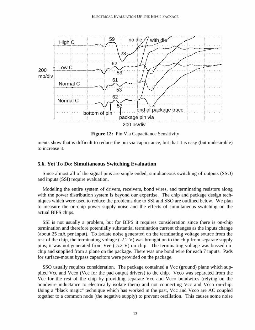
To study the sensitivity of pin capacitance to pin via design, the package incorporated threetypes of pin vias. Most pins used the normal via design preferred by the package vendor: eachfoil layer contained at least a circular pad of copper at the via site to facilitate accurate via holedrilling. After drilling, a small "annular ring" is left behind. The few minimum capacitance testvias contained no pads on unconnected signal layers and large clearances on to power planes.The few large capacitance test vias had large annular rings on signal layers which overlappedwith the power planes (which had small clearances).
Figure 12 shows TDRs of a minimum, a maximum, and two normal pins. For each of thecases there are two overlaid traces, one for a package with a die, one without. These measure-
12
ELECTRICAL EVALUATION OF THE BIPS-0 PACKAGE
High C
Normal C
Low C
Normal C
200mp/div
200 ps/div
with dieno die59
62
61
62
53
53
53
23
package pin via
end of package tracebottom of pin
Figure 12: Pin Via Capacitance Sensitivity
ments show that is difficult to reduce the pin via capacitance, but that it is easy (but undesirable)to increase it.
5.6. Yet To Do: Simultaneous Switching Evaluation
Since almost all of the signal pins are single ended, simultaneous switching of outputs (SSO)and inputs (SSI) require evaluation.
Modeling the entire system of drivers, receivers, bond wires, and terminating resistors alongwith the power distribution system is beyond our expertise. The chip and package design tech-niques which were used to reduce the problems due to SSI and SSO are outlined below. We planto measure the on-chip power supply noise and the effects of simultaneous switching on theactual BIPS chips.
SSI is not usually a problem, but for BIPS it requires consideration since there is on-chiptermination and therefore potentially substantial termination current changes as the inputs change(about 25 mA per input). To isolate noise generated on the terminating voltage source from therest of the chip, the terminating voltage (-2.2 V) was brought on to the chip from separate supplypins; it was not generated from Vee (-5.2 V) on-chip. The terminating voltage was bussed on-chip and supplied from a plane on the package. There was one bond wire for each 7 inputs. Padsfor surface-mount bypass capacitors were provided on the package.
SSO usually requires consideration. The package contained a Vcc (ground) plane which sup-plied Vcc and Vcco (Vcc for the pad output drivers) to the chip. Vcco was separated from theVcc for the rest of the chip by providing separate Vcc and Vcco bondwires (relying on thebondwire inductance to electrically isolate them) and not connecting Vcc and Vcco on-chip.Using a "black magic" technique which has worked in the past, Vcc and Vcco are AC coupledtogether to a common node (the negative supply) to prevent oscillation. This causes some noise
13

ELECTRICAL EVALUATION OF THE BIPS-0 PACKAGE
on negative supply which has some small effect on the current sources. Vcco was bussed on-chip with one bond wire for each 3 or 4 outputs. Vcc and Vee were gridded on-chip in metallayers 3 and 4. Pads for surface-mount bypass capacitors were provided for Vcc on the package.
6. Conclusions
The performance of the BIPS-0 package is better than is required for the BIPS-0 chip and willsuffice for BIPS-1. Use of the ZIF socket only slightly degrades the signals: the BIPS-0 pack-age in a ZIF socket is capable of passing 150 ps rise time signals.
The package impedance is acceptable at 60 Ω and improvement is expected. Impedance dis-continuities due to the PCB plated through holes, ZIF socket, pins, pin vias, traces, bond wiresand chip I/O pads are all small and acceptable.
Crosstalk to an adjacent trace with a single signal switching was found to be under 10% andneeds to be considered in the PCB signal noise budget.
The on-chip terminating resistors are great: electrically they work well (right resistance, noimpedance discontinuities, no stubs) and their power dissipation is not a problem for the BIPSchips.
PCB-mounted SMA and Nanohex connectors perform inadequately for monitoring the fewhigh-frequency analog test signals which are brought out from the BIPS chip onto the BIPSpackage. Instead future designs will provide lands on the package for standard Cascade 50 Ωmicroprobes on the packages.
The effects of simultaneous switching are yet to be determined.
7. Acknowledgements
Bill Hamburgen did a fine job designing this great package. Richard Evans provided guidanceand assistance in this investigation.
8. References
[1] H.B. Bakoglu. Circuits, Interconnections, and Packaging for VLSI. Addison Wesley,1990.
[2] W. R. Hamburgen and J. S. Fitch. Packaging a 150 W Bipolar ECL Microprocessor. InProceedings 42nd Electronic Components & Technology Conference, pages 412-422. IEEE, SanDiego, California, May 18-20, 1992.
[3] William R. Blood, Jr. MECL System Design Handbook. Motorola SemiconductorProducts Inc., 1988.
[4] Motorola. ECLinPS DATA. Motorola Inc., 1991.
[5] Stephen F. Scheiber. The Nightmare of At-Speed VLSI Testing. Test And MeasurementWorld :51-56, March, 1990.
14

ELECTRICAL EVALUATION OF THE BIPS-0 PACKAGE
WRL Research Reports
‘‘Titan System Manual.’’ ‘‘MultiTitan: Four Architecture Papers.’’
Michael J. K. Nielsen. Norman P. Jouppi, Jeremy Dion, David Boggs, Mich-
WRL Research Report 86/1, September 1986. ael J. K. Nielsen.
WRL Research Report 87/8, April 1988.‘‘Global Register Allocation at Link Time.’’
David W. Wall. ‘‘Fast Printed Circuit Board Routing.’’
WRL Research Report 86/3, October 1986. Jeremy Dion.
WRL Research Report 88/1, March 1988.‘‘Optimal Finned Heat Sinks.’’
William R. Hamburgen. ‘‘Compacting Garbage Collection with Ambiguous
WRL Research Report 86/4, October 1986. Roots.’’
Joel F. Bartlett.‘‘The Mahler Experience: Using an Intermediate WRL Research Report 88/2, February 1988.
Language as the Machine Description.’’
David W. Wall and Michael L. Powell. ‘‘The Experimental Literature of The Internet: An
WRL Research Report 87/1, August 1987. Annotated Bibliography.’’
Jeffrey C. Mogul.‘‘The Packet Filter: An Efficient Mechanism for WRL Research Report 88/3, August 1988.
User-level Network Code.’’
Jeffrey C. Mogul, Richard F. Rashid, Michael ‘‘Measured Capacity of an Ethernet: Myths and
J. Accetta. Reality.’’
WRL Research Report 87/2, November 1987. David R. Boggs, Jeffrey C. Mogul, Christopher
A. Kent.‘‘Fragmentation Considered Harmful.’’ WRL Research Report 88/4, September 1988.Christopher A. Kent, Jeffrey C. Mogul.
WRL Research Report 87/3, December 1987. ‘‘Visa Protocols for Controlling Inter-Organizational
Datagram Flow: Extended Description.’’‘‘Cache Coherence in Distributed Systems.’’ Deborah Estrin, Jeffrey C. Mogul, Gene Tsudik,Christopher A. Kent. Kamaljit Anand.WRL Research Report 87/4, December 1987. WRL Research Report 88/5, December 1988.
‘‘Register Windows vs. Register Allocation.’’ ‘‘SCHEME->C A Portable Scheme-to-C Compiler.’’David W. Wall. Joel F. Bartlett.WRL Research Report 87/5, December 1987. WRL Research Report 89/1, January 1989.
‘‘Editing Graphical Objects Using Procedural ‘‘Optimal Group Distribution in Carry-Skip Ad-Representations.’’ ders.’’
Paul J. Asente. Silvio Turrini.WRL Research Report 87/6, November 1987. WRL Research Report 89/2, February 1989.
‘‘The USENET Cookbook: an Experiment in ‘‘Precise Robotic Paste Dot Dispensing.’’Electronic Publication.’’ William R. Hamburgen.
Brian K. Reid. WRL Research Report 89/3, February 1989.WRL Research Report 87/7, December 1987.
15

ELECTRICAL EVALUATION OF THE BIPS-0 PACKAGE
‘‘Simple and Flexible Datagram Access Controls for ‘‘Link-Time Code Modification.’’
Unix-based Gateways.’’ David W. Wall.
Jeffrey C. Mogul. WRL Research Report 89/17, September 1989.
WRL Research Report 89/4, March 1989.‘‘Noise Issues in the ECL Circuit Family.’’
Jeffrey Y.F. Tang and J. Leon Yang.‘‘Spritely NFS: Implementation and Performance ofWRL Research Report 90/1, January 1990.Cache-Consistency Protocols.’’
V. Srinivasan and Jeffrey C. Mogul.‘‘Efficient Generation of Test Patterns UsingWRL Research Report 89/5, May 1989.
Boolean Satisfiablilty.’’
Tracy Larrabee.‘‘Available Instruction-Level Parallelism for Super-WRL Research Report 90/2, February 1990.scalar and Superpipelined Machines.’’
Norman P. Jouppi and David W. Wall.‘‘Two Papers on Test Pattern Generation.’’WRL Research Report 89/7, July 1989.Tracy Larrabee.
WRL Research Report 90/3, March 1990.‘‘A Unified Vector/Scalar Floating-Point Architec-
ture.’’‘‘Virtual Memory vs. The File System.’’Norman P. Jouppi, Jonathan Bertoni, and DavidMichael N. Nelson.W. Wall.WRL Research Report 90/4, March 1990.WRL Research Report 89/8, July 1989.
‘‘Efficient Use of Workstations for Passive Monitor-‘‘Architectural and Organizational Tradeoffs in theing of Local Area Networks.’’Design of the MultiTitan CPU.’’
Jeffrey C. Mogul.Norman P. Jouppi.WRL Research Report 90/5, July 1990.WRL Research Report 89/9, July 1989.
‘‘A One-Dimensional Thermal Model for the VAX‘‘Integration and Packaging Plateaus of Processor9000 Multi Chip Units.’’Performance.’’
John S. Fitch.Norman P. Jouppi.WRL Research Report 90/6, July 1990.WRL Research Report 89/10, July 1989.
‘‘1990 DECWRL/Livermore Magic Release.’’‘‘A 20-MIPS Sustained 32-bit CMOS Microproces-Robert N. Mayo, Michael H. Arnold, Walter S. Scott,sor with High Ratio of Sustained to Peak Perfor-
Don Stark, Gordon T. Hamachi.mance.’’WRL Research Report 90/7, September 1990.Norman P. Jouppi and Jeffrey Y. F. Tang.
WRL Research Report 89/11, July 1989.‘‘Pool Boiling Enhancement Techniques for Water at
Low Pressure.’’‘‘The Distribution of Instruction-Level and MachineWade R. McGillis, John S. Fitch, WilliamParallelism and Its Effect on Performance.’’
R. Hamburgen, Van P. Carey.Norman P. Jouppi.WRL Research Report 90/9, December 1990.WRL Research Report 89/13, July 1989.
‘‘Writing Fast X Servers for Dumb Color Frame Buf-‘‘Long Address Traces from RISC Machines:fers.’’Generation and Analysis.’’
Joel McCormack.Anita Borg, R.E.Kessler, Georgia Lazana, and DavidWRL Research Report 91/1, February 1991.W. Wall.
WRL Research Report 89/14, September 1989.
16

ELECTRICAL EVALUATION OF THE BIPS-0 PACKAGE
‘‘A Simulation Based Study of TLB Performance.’’ ‘‘Cache Write Policies and Performance.’’
J. Bradley Chen, Anita Borg, Norman P. Jouppi. Norman P. Jouppi.
WRL Research Report 91/2, November 1991. WRL Research Report 91/12, December 1991.
‘‘Packaging a 150 W Bipolar ECL Microprocessor.’’‘‘Analysis of Power Supply Networks in VLSI Cir-William R. Hamburgen, John S. Fitch.cuits.’’WRL Research Report 92/1, March 1992.Don Stark.
WRL Research Report 91/3, April 1991.‘‘Observing TCP Dynamics in Real Networks.’’
Jeffrey C. Mogul.
WRL Research Report 92/2, April 1992.‘‘TurboChannel T1 Adapter.’’
David Boggs.‘‘Systems for Late Code Modification.’’WRL Research Report 91/4, April 1991.David W. Wall.
WRL Research Report 92/3, May 1992.‘‘Procedure Merging with Instruction Caches.’’
Scott McFarling.‘‘Piecewise Linear Models for Switch-Level Simula-WRL Research Report 91/5, March 1991.
tion.’’
Russell Kao.‘‘Don’t Fidget with Widgets, Draw!.’’WRL Research Report 92/5, September 1992.Joel Bartlett.
WRL Research Report 91/6, May 1991.
‘‘Pool Boiling on Small Heat Dissipating Elements in
Water at Subatmospheric Pressure.’’
Wade R. McGillis, John S. Fitch, William
R. Hamburgen, Van P. Carey.
WRL Research Report 91/7, June 1991.
‘‘Incremental, Generational Mostly-Copying Gar-
bage Collection in Uncooperative Environ-
ments.’’
G. May Yip.
WRL Research Report 91/8, June 1991.
‘‘Interleaved Fin Thermal Connectors for Multichip
Modules.’’
William R. Hamburgen.WRL Research Report 91/9, August 1991.
‘‘Experience with a Software-defined Machine Ar-
chitecture.’’
David W. Wall.
WRL Research Report 91/10, August 1991.
‘‘Network Locality at the Scale of Processes.’’
Jeffrey C. Mogul.
WRL Research Report 91/11, November 1991.
17

ELECTRICAL EVALUATION OF THE BIPS-0 PACKAGE
WRL Technical Notes
‘‘TCP/IP PrintServer: Print Server Protocol.’’ ‘‘Systems for Late Code Modification.’’
Brian K. Reid and Christopher A. Kent. David W. Wall.
WRL Technical Note TN-4, September 1988. WRL Technical Note TN-19, June 1991.
‘‘TCP/IP PrintServer: Server Architecture and Im- ‘‘Unreachable Procedures in Object-oriented Pro-
plementation.’’ gramming.’’
Christopher A. Kent. Amitabh Srivastava.
WRL Technical Note TN-7, November 1988. WRL Technical Note TN-21, November 1991.
‘‘Smart Code, Stupid Memory: A Fast X Server for a ‘‘Cache Replacement with Dynamic Exclusion’’
Dumb Color Frame Buffer.’’ Scott McFarling.
Joel McCormack. WRL Technical Note TN-22, November 1991.
WRL Technical Note TN-9, September 1989.‘‘Boiling Binary Mixtures at Subatmospheric Pres-
‘‘Why Aren’t Operating Systems Getting Faster As sures’’
Fast As Hardware?’’ Wade R. McGillis, John S. Fitch, William
John Ousterhout. R. Hamburgen, Van P. Carey.
WRL Technical Note TN-11, October 1989. WRL Technical Note TN-23, January 1992.
‘‘Mostly-Copying Garbage Collection Picks Up ‘‘A Comparison of Acoustic and Infrared Inspection
Generations and C++.’’ Techniques for Die Attach’’
Joel F. Bartlett. John S. Fitch.
WRL Technical Note TN-12, October 1989. WRL Technical Note TN-24, January 1992.
‘‘Limits of Instruction-Level Parallelism.’’ ‘‘TurboChannel Versatec Adapter’’
David W. Wall. David Boggs.
WRL Technical Note TN-15, December 1990. WRL Technical Note TN-26, January 1992.
‘‘The Effect of Context Switches on Cache Perfor- ‘‘A Recovery Protocol For Spritely NFS’’
mance.’’ Jeffrey C. Mogul.
Jeffrey C. Mogul and Anita Borg. WRL Technical Note TN-27, April 1992.WRL Technical Note TN-16, December 1990.
‘‘Electrical Evaluation Of The BIPS-0 Package’’
‘‘MTOOL: A Method For Detecting Memory Bot- Patrick D. Boyle.
tlenecks.’’ WRL Technical Note TN-29, July 1992.Aaron Goldberg and John Hennessy.
‘‘Transparent Controls for Interactive Graphics’’WRL Technical Note TN-17, December 1990.Joel F. Bartlett.
‘‘Predicting Program Behavior Using Real or Es- WRL Technical Note TN-30, July 1992.timated Profiles.’’
David W. Wall.
WRL Technical Note TN-18, December 1990.
18

ELECTRICAL EVALUATION OF THE BIPS-0 PACKAGE
ii

ELECTRICAL EVALUATION OF THE BIPS-0 PACKAGE
Table of Contents1. Introduction 12. Evaluation Techniques 13. Making the connection - how suitable are RF connectors? 54. Package Electrical Characteristics 75. Measurement Results 8
5.1. Package Impedances and On-chip Termination - TDR 85.2. ZIF Socket Performance 105.3. Edge Rates through Package - TDT 105.4. Crosstalk 115.5. Package Pin Via Capacitance 125.6. Yet To Do: Simultaneous Switching Evaluation 13
6. Conclusions 147. Acknowledgements 148. References 14
iii

ELECTRICAL EVALUATION OF THE BIPS-0 PACKAGE
iv

ELECTRICAL EVALUATION OF THE BIPS-0 PACKAGE
List of FiguresFigure 1: TDR Test Setup 2Figure 2: Oscilloscope Trace of TDR with Inductive and Capacitive Discon- 3
tinuitiesFigure 3: TDR Quality and Connections 4Figure 4: TDR with Nanohex and SMA connectors 5Figure 5: Soldered Coax to Pin Connection 6Figure 6: Coax to Bond Pad Connection 7Figure 7: TDR of Input Pins 9Figure 8: TDR of Output Pins 9Figure 9: TDR and TDT with and without ZIF Socket 10Figure 10: Rise Times as a Function of Swing 11Figure 11: Forward and Backward Crosstalk 12Figure 12: Pin Via Capacitance Sensitivity 13
v