electricalpartmanuals . com · pdf file• load center circuit breakers • load centers...
TRANSCRIPT

January 1 992 Supersedes Cata log 30-350, pages 1 -44, dated December 1990 For standard terms of sale, refer to Sel l i ng Policy 25-000 Mailed to: E, D, C/30-1 00A, 30-200A
Westinghouse Electric Corporation Distribution and Control Busi ness U nit Sta ndard Distri bution Products Division Pittsburgh, Pennsylva nia , U .S.A. 1 5220
Catalog 30-350
Page 1
Circuit Protective Devices • Load Center Circuit Breakers • Load Centers • Meter Breaker Panels • Meter Centers • U nit Enclosures
www . El
ectric
alPar
tMan
uals
. com

Catalog 30-350
Page 2
Table of Contents, Specifications and Listings
Table of Contents
Specifications, Listi ngs . . . . . . . . . . . . . .
Circuit Breakers Circuit Breaker Types . . . . . . . . . . . . . . . Ci rcuit Breaker Features, D imensions Ci rcuit Breaker 1" per Pole . . . . . . . . . . Circuit Breaker Handle Color Code . . . C i rcuit B reakers 1/2' per Pole,
Replacement Breakers, and Special Appl ication Brea kers . . . . . . . . . . . . . .
Ci rcuit Breaker Rat ings and Terminal Data . . . . . . . . . . . . . . . . . . . . . . . . . . . . .
Circuit Breaker Accessories and Wire Ranges . . . . . . ... . . . . . . . . . . . . . . . . . .
Load Centers Load Center Features and Catalog
N u mber Interpretation . . . . . . . . . . . . Ma in Breaker, Single Phase Load
Cen�� . .. . . . . . . . . . . . . . . . . ... . . . . Main Breaker, Th ree Phase Load
Centers . . . . . . . . . . . . . . . . . . . . . . . . . . Main Lug, Si ngle Phase Load
Centers . . . . . . . . . . . . . . . . . . . . . . ... . Main Lug, Three Phase Load
Centers . . . . . . . . . . . . . . . . . . . . . . . . . . Mod/Line Load Centers . . . ... .. . . . . . . Unit Enclosures .. . . . . . . . . . . . . . . . . . . . Load Center Accessories . . . . . . . . . . . . Load Center Dimensions and Knock-
Specifications, Listings
Page Class CTL (Current Twin Limiting) 2 National E lectrical Code Paragraph 384- 1 5
requ i res branch c i rcuit load centers t o be provided with physical means to prevent
3 the instal lation of more over-current devices
4 than that n u mber for which the enclosure
5 was desig ned, rated, and approved. Class 5 CTL Duplex and Ouadplex breakers ( identi-
fied by a catalog n u mber prefix BD, BO or BOC) a re equ i pped with a U L l isted rejection
6 tab over the l i ne termina l. Al l load center enclosures have appropriately notched
7 stabs to accept these rejection tab Class CTL breakers. ( Refer to Wir ing Diagrams on
8 pages 37-39.)
Duplex and Ouadplex breakers manufactured without the rejection tab ( identified by
9 a catalog nu mber prefix BR or BRD) a re avai lable for replacement pu rposes in older
10 enclosures.
1 1
1 2
1 3
Federal Specifications All load center enclosu res meet Federal Specifications W-P-1 1 5a, Type 1 , Class 2 req u irements.
14 All 1 20/240 volt breakers, both 1" and V2' 1 5 per pole meet the requ i rements of Federal
1 6 Specifications W-C-375B/Gen Type 1 .
out Data . .. . . . . . . . . . . . . . . . . ... 1 7, 1 8, 1 9 Canadian Standards Association Listing
Meter Breaker Panels Meter Breaker Panels . . . . . . . . . . . . . . . Meter Breaker Panel Dimensions and
Knockout Data Wir ing Diagram .. . . Residential House Panel . . . . . . . . . . . . .
Dimensions and Wir ing Schematics . . . . . . . . . . . . ... . . . . . . . .
WM Modular Metering Main Service Cu bicles .. . . . . . . . . . . . . Meter Module Featu res . . . . . . . . . . . . . Stacks Type WM, Si ngle Phase . . . . . . Com mercial Meter Stacks .. . . . . . . . . .
Meter Centers Meter-Packs, Single Phase .. . . . . . .
D imensions and Installation . . . . . . .
WM Modular Metering Main Tenant Breakers, Accessories . .
Dimensions and Knockout I nfo . . . . Typical Meter Stack Schematics . . . . . Main Breaker and Ma in Lug
20, 21
22, 23 24
25
26, 27 28 29 30
32 33
34 36
37, 38
Al l 1 , 2, and 3 pole, 1 20/240 volt breakers, both 1" and 1/2' per pole, 225 am pere maximum, a re l i sted as Certified by the Canadian Sta ndards Association , Gu ide N o. 69-1 1 . 1 9, Class 1 432, File 1 8328.
All 1 and 2 pole G FCB® G round Fau lt Circuit Brea kers a re l i sted as certified by the Canadian Standards Association, G u ide No. 1 42-R-3, Class 1 45 1 , File 33607.
Service Entrance All main breaker and u nit enclosures, and a l l main lug enclosures thru 12 ci rcu it s ing le phase and 18 circuit th ree phase a re l isted as su itable for use as Service Equ i pment when insta l led in accordance with Article 230-71 and Article 384- 1 6 of the National E lectrical Code. Refer to "Six Circuit Rule." Meter socket un its are l i sted as Service Equi pment.
Schematics . . . . . . . . . . . . . . . . . . . 39, 40, 41
This information is i ncl uded on the wir ing diagram as sta ndard, no special label is requ i red.
Replacement Parts . . . . . . . . . . . . . . . . . .
Notes .. .. . . . . . . . . . . . . . . . . . . . . . . . . . .
Typical Load Center Assembly . . . . . . .
42 These articles requ i re that: a. Panels used as service entrance equ ip-
43 ment must be located near the point where the supply conductors enter the
44 bui ld ing . b . A Load Center having main lugs only
shall have a maxi m u m of six operating hand les to discon nect the entire Load Center from the supply conductors.
Where more than six d iscon nects a re requi red, a ma in c i rcuit breaker or ma in d isconnect switch must be provided.
c. Must i nc lude connector for bonding and grou nding neutra l conductor.
Underwriters' Laboratories Inc. Listing All load centers com ply with the Underwriters' Laboratories Inc. standards and a re l isted as fo l lows:
"Standard for Panelboa rds" U L67; G u ide No. 320 BO File E31 679 and E52977.
"Sta ndards for Cabi nets and Boxes" U L50; Gu ide No. 60 A 1 9 File E34724.
"Requ i rements for Wire Connectors and Soldering Lugs", U L486; G uide No. 461 1 0-C File E7830.
"Requirements for Service Equ i pment", U L869; G u ide No. 380 FO Fi le E 1 1 737.
Al l M LK series lug kits comply with Underwriters' Laboratories Inc. sta ndards and a re l isted u nder G u ide No. DHJR, File E31424, Volume W, Section 1 7 .
Al l g rou nding bars man ufactured comply with Underwriters' Laboratories I nc. standards and a re listed u nder G u ide No. DHJR, File E31 424, Volume W, Section 1 7 .
All c ircuit breakers 1 0 am peres and la rger com ply with the Underwriters' Laboratories Inc. "Standard for B ranch Circuit and Service Ci rcuit-Brea kers" U L489; G uide No. 60 1 0 .2 Fi le E31 424, and "Requ i rements for Wire Con nectors and Solder ing Lugs", U L486; G u ide No. 461 1 0-C Fi le E7830.
All West inghouse brea kers and load centers where ma rked, a re suitable for use with 60/ 75oC rated wi re.
All devices comply with the 22,000 A. I.C. -1 0,000 A. I. C. U . L. series con nected components Fi le DKSY2 of the Recog nized Components I ndex.
Lighting and Appliance Panelboards Lighting and appl iance branch c i rcu it panelboards a re defined in N . E.C. (Article 384) as "One having more than 10 per cent of its overcu rrent devi ces rated 30 am peres or less for which neutra l con nections a re provided". Article 384 a lso l i m its the n u m ber of overcurrent devices (branch c i rcuit poles) to a maxi mum of 42 in any one ca binet. When the 42 poles a re exceeded, two or m ore separate panels a re requ i red and may be electrica l ly connected by Sub Feed Lug Kits.
January 1992
0
www . El
ectric
alPar
tMan
uals
. com
BR
GFEP Equipment Protection
BD
WFP2200T Kit (Obsolete)
January 1992
) ) i
GFCB'" People Protection
BJ
BQ
Special Application
WFP2200T2
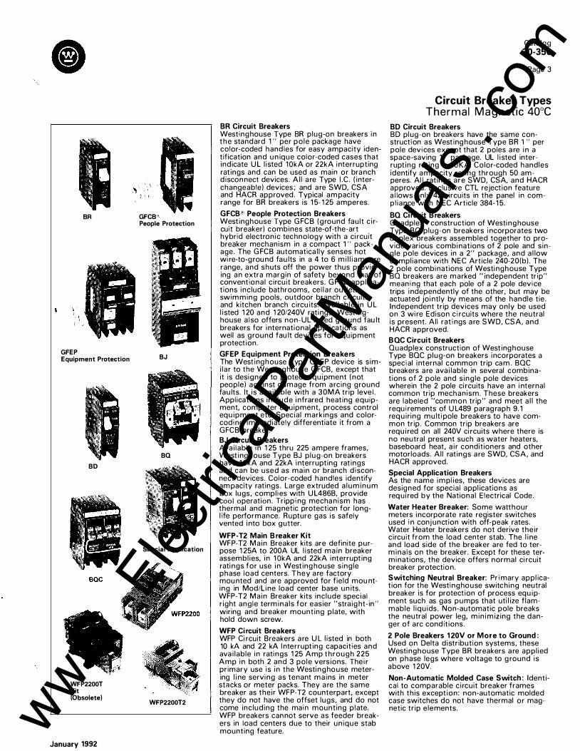
BR Circuit Breakers Westinghouse Type BR plug-on breakers in the standard 1 " per po le package have color-coded hand les for easy ampacity identification and u n ique color-coded cases that indicate U L l isted 1 OkA or 22kA i nterrupting rat ings and can be used as main or bra nch d iscon nect devices. Al l a re Type I.C. ( interchangeable) devices; and a re SWD, CSA and HACR approved. Typical am pacity range for BR breakers is 1 5- 1 25 amperes.
GFCB"' People Protection Breakers Westinghouse Type G FCB (ground fault c i rcuit breaker) combines state-of-the-art hybrid electronic technology with a ci rcuit breaker mechanism in a com pact 1 " package. The G FCB automatica l ly senses hot wi re-to-g rou nd fau lts in a 4 to 6 m i l l i ampere range, and shuts off the power thus providing an extra margin of safety beyond that of conventiona l c ircuit breakers. G FCB appl ications i nclude bathrooms, cel l a r outlets, swim ming pools, outdoor branch circuits, and kitchen branch circu its. Avai lab le in U L l i sted 1 20 and 1 20/240V rati ngs. Westinghouse a lso offers non-UL l i sted g round fau lt breakers for i nternational appl ications as well as ground fau lt devices for equipment protection.
GFEP Equipment Protection Breakers The West inghouse Type GFEP device is s imi la r to the Westinghouse G FCB, except that it is designed to protect equi pment ( not people) against damage from a rcing ground fau lts. It i s ava i lab le with a 30MA tr ip leve l . Applications inc lude i nfrared heating equipment. computer equipment, process control equ ipment etc. Specia l markings and colorcoding immediately differentiate it from a GFCB breaker. BJ Circuit Breakers Avai lab le in 1 25 thru 225 ampere frames, West inghouse Type BJ p lug-on breakers have 1 OkA and 22kA i nterrupting rat ings and can be used as main or branch disconnect devices. Color-coded handles identify am pacity ratings. Large extruded a luminum box lugs, complies with U L486B, provide cool operation. Tripping mecha nism has thermal and mag netic protection for longl ife performance. Rupture gas is safely vented i nto box gutter.
WFP-T2 Main Breaker Kit WFP-T2 Main Breaker kits are definite purpose 1 25A to 200A UL l i sted main breaker assembl ies, i n 1 OkA and 22kA i nterrupt ing rati ngs for use i n West ing house s ingle phase load centers. They a re factory mou nted and are approved for f ield mou nting in Mod/Li ne load center base un its. WFP-T2 Main Breaker kits inc lude specia l r ight ang le term ina ls for easier "stra ig ht-in" wiring and breaker mounting p late, with hold down screw.
WFP Circuit Breakers WFP Ci rcuit Breakers a re U L l isted in both 10 kA and 22 kA I nterrupt ing capacities and ava i lab le i n rati ngs 1 25 Amp through 225 Amp i n both 2 and 3 po le versions. Thei r primary use is i n the Westi nghouse metering l i ne servi ng as tenant ma ins in meter stacks or meter packs. They a re the same breaker as their WFP-T2 counterpart, except they do not have the offset lugs, and do not come inc luding the main mounting p late. WFP breakers can not serve as feeder breakers in load centers due to their un ique stab mounting feature.
Cata log 30-350
Page 3
Circuit Breaker Types Thermal M a g n etic 40°C
BD Circuit Breakers BD pl ug-on breakers have the same construction as West inghouse Type BR 1" per pole devices except that 2 poles a re i n a space-saving 1 " package. UL l i sted interrupt ing rat ing is 1 OKA. Color-coded handles identify ampacity rat ing through 50 amperes. Al l rat ings are SWD, CSA, and HACR approved. Exclusive CTL rejection feature a l lows only 42 circuits in the panel in comp l iance with NEC Article 384- 1 5.
BQ Circuit Breakers Ouadplex® construction of Westi nghouse Type BO plug-on breakers i ncorporates two duplex breakers assembled together to provide various combi nations of 2 pole and s ing le pole devices in a 2" package, and a l low complia nce with NEC Article 240-20(b) . The 2 pole combi nations of Westi nghouse Type BO breakers are marked "independent trip" meaning that each pole of a 2 pole device trips i ndependently of the other, but may be actuated joi ntly by means of the handle tie. Independent trip devices may only be used on 3 wi re Edison circuits where the neutral i s present. Al l ratings a re SWD, CSA, and HACR approved.
BQC Circuit Breakers Ouadplex construction of West inghouse Type BOC plug-on breakers i ncorporates a special i nternal common trip ca m . BOC breakers a re ava i lab le in several combinations of 2 pole and s ing le pole devices wherein the 2 pole ci rcuits have an i nternal com mon trip mechanism. These breakers are labeled "common trip" and meet a l l the requirements of U L489 parag raph 9. 1 requ i ring mu ltipole breakers to have common trip. Common trip breakers are requ i red on all 240V ci rcuits where there is no neutral present such as water heaters, baseboard heat. a i r conditioners and other motorloads. Al l rat ings a re SWD, CSA. and HACR approved.
Special Application Breakers As the name i m pl ies, these devices are designed for specia l appl ications as req ui red by the Nationa l E lectrical Code.
Water Heater Breaker: Some watthour meters i ncorporate rate register switches used in conj unction with off-peak rates. Water Heater breakers do not derive their c ircuit from the load center stab. The l i ne and load side of the breaker are fed to termina ls on the breaker. Except for these termi nations, the device offers normal ci rcuit breaker protection .
Switching Neutral Breaker: Primary appl ication for the Westinghouse switching neutral breaker is for protection of process equ ipment such as gas pumps that uti l ize f lammable l iqu ids. Non-automatic pole breaks the neutral power leg, m in i m izing the danger of arc condit ions.
2 Pole Breakers 1 20V or More to Ground: Used on Delta d istribution systems, these Westi nghouse Type BR breakers a re appl ied on phase legs where voltage to g round is above 1 20V.
Non-Automatic Molded Case Switch : Identical to comparable c i rcuit breaker frames with this except ion : non-automatic molded case switches do not have thermal or magnetic tr ip e lements. www .
Elec
tricalP
artM
anua
ls . c
om

Catalog 30-350
Page 4
Circuit Breaker Features and Dimensional Data The rm a l M a g n et ic 40°C
Handle position provides On, Off, and Tripped
Heavy duty mechanism spring for reliable operation
Hardened cradle for positive action under fault conditions
Non-abrasive integrally molded pivot for quick mechanism response
One-piece moving contact arm for quick on/off response
Heavy duty line terminal """"
and spring clip for quick load center installation and cool operation
Silver tungsten alloy contacts
"-----" , --�
-Coding: ____ _ 1 Located on :e �� Breaker
-
Unique one-piece heavy-duty De-lon"'' assembly for quick arc interruption
1- Year �-�h __ �� , Example: , �1_0_1 __ -� 1, 1992
1" Per Pole Module BR Series
Color-coded handle for fast identification of ampere ratings
Calibrated one piece bimetal for reliable thermal trip function
%" Per Pole Module BD/BQ Series
Steel frame insures constant calibration for life of breaker
Four-rivet construction enhances strength and structural integrity of breaker case
Common trip cam assures simultaneous pole opening
Heavy duty multi-strand flexible copper shunt provides load terminal torque isolation
UL 4868 approved terminal assembly for use with copper or aluminum wire, screw is "backed out' for faster insertion of wires
Magnetic assembly for reliable short circuit protection
Large gas port for venting short circuit gases safely into load center gutter
type load center holdowns
1" Per Pole Module BJ Series
January 1992
www . El
ectric
alPar
tMan
uals
. com

Catalog 30-350
Page 5
Plug-on Circuit Breakers 1" per pole - Types B R , GFCB, G FEP, BJ , WFP-T2 The rm a l Ma g n etic 40°C
BR120
I___ -------------------------Type BR Breakers, 1" Per Pole 1 20/240 or 240 Volts AC, 10,000, 22,000, and 42,000 AIC@Q)
1 Pole 2 Pole :=-r:;-=: 120/240 VAC � 120/240 VAC Common Trip
Requires 1 Space Requires 2 Spaces Amps 12 per Shelf Carton; 6 per Shelf Carton; 24 per 16 Lb Package
48 per 14 Lb. Package 10,000 AIC 22,000 AIC 10,000 AIC 22,000 AIC 42,000 AIC
Cat. No. Cat. No. Cat. No.CD Cat. No.CD Cat. No.CD 10 BR110® BR210 15 BR115®@ BRH 1 1 5 BR215 BRH215 20 BR120®@ BRH120 BR220 BRH220 25 BR125 BRH125 BR225 BRH225 30 BR130 BRH130 BR230 BRH230 40 BR140 BRH140 BR240 BRH240 50 BR150 BRH150 BR250 BRH250 60 BR160 BRH160 BR260 BRH260 70 BR170 BRH170 BR270 BRH270 80 BR280 90 BR290 BRH290
100 BR2100 BRH2100 BRHH2100 110 BR2110 BRH2110 BRHH2110 125 BR2125 BRH2125 BRHH2125
Type GFCB Ground Fault Circuit Breakers 1' Per Pole 120VAC or 120/240VAC, 10,000 and 22,000 AIC
3 Pole 240 VAC Common Trip �- J�. . � .
. ' _ _.
Requ1res 3 Spaces 4 per Shelf Carton; 16 per 17 Lb. Package 10,000 AIC 22,000 AIC
Cat. No.CD Cat. No.CD
BR315 BRH315 BR320 BRH320
BR330 BRH330 BR340 BRH340 BR350 BRH350 BR360 BRH360 BR370 BRH370
BR390 BRH390 BR3100 BRH3100
1 Pole for Single Circuit Application, 2 Pole for Multi-Wire and Appliance Circuits.
-� _,..r\;.,. 1 Pole 2 Pole -
l u. ...JVV-A_ 120 VAC 120/240 VAC Common Trip Amps Requires 1 Space 1P5MA for Requires 2 Spaces 2P5MA for mult1-
1 per Shelf Carton single circuit 1 per Shelf Carton wire and appliance 20 per 10 Lb. Package application 5 per 6 Lb. Package CirCUitS 10,000 AIC 22,000 AIC 10,000 AIC 22,000 AIC
Cat. No. Cat. No. Cat. No. Cat. No.
15 GFCB 1 1 5 GFCBH1 1 5 GFCB215 GFCBH215 20 GFCB120 GFCBH120 GFCB220 GFCBH220
25 GFCB125 GFCBH125 GFCB225 GFCBH225 30 GFCB130 GFCBH130 GFCB230 GFCBH230 40 GFCB240®
Type BJ Breakers, 1 20/240 or 240 Volts AC, 1 0,000, 22,000 AIC
�� ·-��\ . 2 Pole ____.,r-� 3 Pole ::::-�+ :=: 120/240 VAC Common Trip 240 VAC Common Trip
Amps Requires 4 Spaces Requires 6 Spaces 1 per Shelf Carton, 10 per 20 Lb. Package 1 per Shelf Carton, 5 per 18 Lb. Package 10,000 AIC 22,000 AIC Cat. No.CD Cat. No.CD
125 BJ2125 BJH2125 150 BJ2150 BJH2150 175 BJ2175 BJH2175 200 BJ2200 BJH2200 225 BJ2225 BJH2225
CD 2-pole and 3-pole breakers 40 amp and larger are available with MAIN stamped on handle or case. Add suffix "B" to catalog number.
® One pole, 1" per pole breakers are available with high magnetic setting for switching large tungsten lamp loads. Add suffix H to catalog number.
@ BR-1, 2-, and 3-pole breakers also carry listing for HACR application.
January 1992
10,000 AIC 22,000 AIC Cat. No.CD Cat. No.CD BJ3125 BJH3125 BJ3150 BJH3150 BJ3175 BJH3175 BJ3200 BJH3200 BJ3225 BJH3225
® Switching duty rating. 0) For use with copper wire only and CSA Listed. 0 For breakers with shunt trip capabilities, see HOP type.
WFP2200T2 Kit
Type GFEP Ground Fault Equipment Protectors, 1" per Pole 120VAC or 120/240VAC, 1 0,000 AIC
1 Pole 2 Pole 120 VAC 120/240 VAC Requires 1 Space Requires 2 Spaces
Amps 1 per Shelf Carton 1 per Shelf Carton 20 per 9 Lb. Package 5 per 5 Lb. Package 1P30MA for 2P30MA for single circuit multi-wire and application appliance circuits
Cat. No. Cat. No
15 GFEP 1 1 5 GFEP215 20 GFEP120 GFEP220 25 GFEP125 GFEP225 30 GFEP130 GFEP230
Types WFP and WFPH Main Breaker Kits -120/240 Volts AC- 1 0,000, 22,000 AIC For Field- Instal l ed Mains, with Mou nting Plate I ncluded®
Amps 2-Pole Breakers Load
10,000 AIC 22,000 AIC Terminal Wire Range,
Cat. No. Cat. No. Cu/AI
125 WFP2125T2 WFPH2125T2 #1-300 MCM 150 WFP2150T2 WFPH2150T2 175 WFP217 5T2 -
200 WFP2200T2 WFPH2200T2
@ Remove Suffix "2" for use wtth prev1ous Type Load Centers produced before 1991. lex. WFP2200T)
Circuit Breaker Handle Color Code
Amps Color Amos Color 10 PINK 70 YELLOW 15 MED. BLUE 90 DARK RED 20 MED. RED 100 BLACK 25 IVOR Y 125 DARK GREEN 30 MED. GREEN 150 BROWN 40 GRAY 175 AMBER 50 LT. BLUE 200 DARK BROWN 60 ORANGE 225 DARK BLUE
Circuit Breaker Case Interrupting Capacity
10,000 AI. C. Black 22,000 A I. C. Gray
Typical Installation www . El
ectric
alPar
tMan
uals
. com

Catalog 30-350
Page 6
Plug-on Circuit Brea kers %"per po l e - Type CTL The rma l Ma g n etic 40°C
BD1 520
Class CTL 10,000 AIC Al l breakers have rejection tab feature.
120/240 VAC Duplex Type BD® ® 120/240 VAC Quadplex Type 80 Independent Trip® Two of 1-Pole Takes 1 Space Two of 2-Pole or One 2-Pole and
12 Shelf Carton � 48 per 17 Lb. Package
Two 1-Pole Takes 2 Spaces
6 per Shelf Carton 24 per 18 Lb. Package
:;gl!gl'o-riy
Amps Cat. No. Amps Cat. No. 10-10 BD1010 2p15-2p15 80215215 1 5-15 801515 2p20-2p20 80220220 15-20 801520 2p20-2p30 80220230 15-30 BD1530 2p20-2p40 80220240 20-15 BD2015 2p20-2p50 80220250 20-20 802020 2p25-2p25 80225225 20-30 802030 2p30-2 of 1p1 5 8023021 15 25-25 BD2525 2p30-2 of 1 p20 802302120 30-15 BD3015 2p30-2p30 80230230 30-20 BD3020 2p30-2p40 80230240 30-30 BD3030 2p30-2p50 80230250 30-40 BD3040 2p40-2 of 1 p15 802402115 30-50 803050 2p40-2 of 1 p20 802402120 50-30 BD5030 2p40-2p40 80240240
2p40-2p50 80240250 2p50-2 of 1 p15 8025021 1 5 2p50-2 of 1 p20 802502120 2p50-2p50 80250250
Non-CTL 1 0,000 AIC For Replacement Purposes Only
120/240V and 240 VAC Type BOC Common Trip® Two of 2-Pole 240 V or One 2-Pole 240 V and Two 1 -Pole 120;240 V Takes 2 Spaces 2-Pole Devices are Common Trip :;gl!gl'o-6 per Shelf Carton riy 24 per 1 8 Lb. Package Amps Cat. No. 2p252 of 1 p15 Com. Trip BOC22521 15 2p302 of 1 p15 Com. Trip BOC23021 15 2p302 of 1 p20 Com. Trip BOC2302120 2p402 of 1 p15 Com. Trip BOC24021 1 5 2p402 o f 1 p20 Com. Trip BOC2402120 2p502 of 1 p15 Com. Trip BOC2502 1 1 5 2p502 of 1 p20 Com. Trip BOC2502120 2p152p1 5 Com. Tri p BOC215215 2p202p20 Com. Trip BOC220220 2p202p30 Com. Trip BOC220230 2p202p40 Com. Trip BOC220240 2p202p50 Com. Trip BOC220250 2p252p25 Com. Trip BOC225225 2p302p30 Com. Trip BOC230230 2p302p40 Com. Trip BOC230240 2p302p50 Com. Trip BOC230250 2p402p40 Com. Tri p BOC240240 2p402p50 Com. Trip BOC240250 2p502p50 Com. Trip BOC250250
For replacement in enclosures manufactured prior to 1 968 with u nnotched stabs®. Al l breakers do not have rejection tab.
120/240 VAC Duplex®® 120/240 VAC Ouadplex Type BRD® 12 per Shelf Carton, 48 per 1 7 Lb. Carton 6 per Shelf Carton, 24 per 18 Lb. Carton Amps Cat. No. 1 5-15 BR1515 1 5-20 BR1520 20-15 BR2015 20-20 BR2020 30-30 BR3030
Special Application Breakers
Water Heater Breakers
2 Pole, 120/240 VAC � LINE 10,000 AIC 6 per Shelf Carton LOAD 24 per 1 5 Lb. Package With Isolated Line Terminals for Separately Mounted Water Heaters Requires 2 Spaces Amps Cat. No. 15 BRWH215 20 BRWH220 30 BRWH230
G.J Sw1tchmg duty rated. ® Two of 1-pole takes 1 space.
Amps 2p152p15 2p202p20 2p302p30 2p302p40 2p302p50
Switching Neutral Breakers
2 Pole, 120 VAC � 10,000 AIC OUT 6 per Shelf Carton NEUTRAL IN 24 per 15 Lb. Package With Switching Neutral Pole for Gas Stations Requires 2 Spaces Amps Cat. No. 15 BRSN215 20 BRSN220 30 BRSN230
Cat. No. BR415 BR420 BR430 BRD230240 BRD230250
Delta 240V Breakers
2 Pole, 240 VAC 10,000 AIC � 6 per Shelf Carton 24 per 16 Lb. Package Where Voltage Exceeds 120 Volts to Ground Requires 2 Spaces Amps Cat. No. 15 BR215H 20 BR220H 30 BR230H 40 BR240H 50 BR250H 60 BR260H 70 BR270H
@ Two of 2-pole 240V takes 2 spaces. @ All BD, BO and BOC Breakers carry listing for HACR
applications.
120/240 VAC Ouadplex Type BRDC® 6 per Shelf Carton, 24 per 18 Lb. Carton Amps Cat. No. 2p1 52p 1 5 Com. Trip BRDC215215 2p302p30 Com. Trip BRDC230230 2p302p40 Com. Trip BROC230240 2p302p50 Com. Trip BRDC230250
Non-Automatic Molded Case Switches
2 Pole, 240 VAC :0= 3 Pole, 240 VAC 5000 Amps Withstand Rating For use as Disconnect Contains No Magnetic or Thermal Trip Properties
Amps Poles Cat. No. 50 2 BR250NA 60 2 BR260NA
1 00 2 BR2100NA 225 2 BJ2225NA 1 00 3 BR3100NA 225 3 BJ3225NA
® See Typical Installation for Notched Stab Illustration on page 5.
January 1992
www . El
ectric
alPar
tMan
uals
. com

Type Amp Rating Fed Spec UL Listed Interrupting
Catalog 30-350
Page 7
Circu it Brea ker Ratings and Term inal Data
Capacity RMS SYMAmps Terminal Data W-C-375b 120/240 VAC 240 VAC Term Type Wire Type No. AWG Range
60/75-c BD 15-50 10a,11a,12a 10000
BO 15-50 10a, 1 1a, 12a 10000
BR 15-125 10a,11a,12a 10000 ( 15-50A) #4-#14 BD, BO ( 15-30A) #8-#14 BR
BRH 15-125 14a, 14b 22000 Pressure CU AL 1 (40-50A) #4-#10 BR
BRHH 100-125 14a, 14b 42000 (50-110A) #1/0-#8 BR 125A #2/0 BR
BJ 125-225 12a, 12b 10000 10000 #2-300 MCM (125&225A) BJ BJH 125-225 14a, 14b 22000 22000
BJHH 150-200 14a, 14b 42000 42000
WFP 125-225 14a, 14b 10000 10000 Pressure CU AL 1 1-4/0 Cu
WFPH 125-225 14a, 14b 22000 22000 Pressure CU AL 1 2/0-300 MCM AI
OK 125-400 21a 65000 TA400K 2 #310-250 MCM TA350KCD CU AL 1 250-500 MCM
LA600 500-600 21a 42000 TA600LA CU AL 2 250-500 MCM
MA 600-800 21a 42000 TA800MA2 3 #3 0-400MCM
TA700MA1CD CU AL
2 #1-500 MCM
NB 700-1200 21a 42000 TA 1200NB1 4 #410-500 MCM
T A1201NB1CD CU AL
3 500-750 MCM
PB 600-1600 25a 125000 CONNECTOR CU AL 4 #110-750 MCM GFCB, GFEP 15-30 1 Oa, 11 a, 12a 10000 Pressure CU AL 1 15-20A #8-14 GFCB 40 10a, 11a, 12a 10000 Pressure cu 1 40A
GFCBH 15-30 1 Oa, 11 a, 12a 22000 Pressure cu 1 30A #4- 14
Current Carrying Capacities of Conductors CD Alternate T erminals available on special order, or order directly for field installation.
Not more than three conductors in racewav or cable or earth (directlv buried), based on ambient temperature of 30 C (86 F) Exception Table for Ampactity of Conductors
Ampacities of Insulated Conductors @l Three-Wire, Single-Phase Dwelling Services. In dwelling units, conductors, as listed below, shall be permitted to be
Size Temperature R ating of Conductor, See Table 310·13 Size utilized as three-wire, single-phase, service-entrance conductors and three-60 c 75 c 85 c 90 c 60 c 75 c 85 c 90 c wire, single-phase feeder that carries the total current supplied by that service.
1140 FJ 1167 FJ 1185 F) 1194 FJ 1140 FJ 1167 F) 1185 FJ 1194 FJ Grounded service-entrance conductors shall be permitted to be two AWG TYPES TYPES TYPES TYPES TYPES TYPES TYPES TYPES srzes smaller than the ungrounded conductors provided the requirements tRUW. tFEPW. V.MI TA. TBS tRUW. tRH. V.MI TA. TBS, of Sectron 230-42 are met.
AWG tT.tTW, tRH, SA, AVB, tT, tTW, tRHW, SA, AVB, AWG tUF tRHW, SIS, tuF tRUH, SIS, Maximum Number of Conductors in Trade Sizes of Conduit or
MCM tRUH, tFEP. tTHW. tRHH, MCM Tubing (Based on Table 1, Chapter 9) tTHW. tFEPB, tTHWN, tTHHN,
tTHWN, tRHH, tXHHW, tXHHW• Conduit Trade Size (Inches) '12 % 1 1 1/• 1% 2 2V, 3 3V, 4 5 6 tXHHW, tTHHN, tuSE
Type Letters tuSE, tXHHW• Size tZW AWG,
Copper MCM 18 14 TVV, T. RUH, 14 9 15 25 44 60 99 142 16 18 18 RUW, 12 7 12 19 35 47 78 111 171 14 20t 201 25 251 12 251 25) 30 30t 20t 20) 25 25) 12 XHHW 10 5 9 15 26 36 60 85 131 176
10 30 35) 40 40) 25 30) 30 35) 10 114 thru 81 8 2 4 7 12 17 28 40 62 84 108
8 40 50 55 55 30 40 40 45 8 RHW and RHH 14 6 10 16 29 40 65 93 143 192 6 55 65 70 75 40 50 55 60 6 (without outer 12 4 8 13 24 32 53 76 117 157 4 70 85 95 95 55 65 75 75 4 covering), 10 4 6 11 19 26 43 61 95 127 163 3 85 100 110 110 65 75 85 85 3 THW 8 1 3 5 10 13 22 32 49 66 85 133 2 95 115 125 130 75 90 100 100 2 1 110 130 145 150 85 100 110 115 1 TVV. 6 4 7 10 16 23 36 48 62 97 141 0 125 150 165 170 100 120 130 135 0 T. 4 3 5 7 12 17 27 36 47 73 106
00 145 175 190 195 115 135 145 150 00 THW. 3 2 4 6 10 15 23 31 40 63 91 000 165 200 215 225 130 155 170 175 000 RUH 16 thru 21, 2 2 4 5 9 13 20 27 34 54 78
0000 195 230 250 260 150 180 195 205 0000 RUW (6 thru 21, 1 1 3 4 6 9 14 19 25 39 57 250 215 255 275 290 170 205 220 230 250 300 240 285 310 320 190 230 250 255 300 FEPB 16 thru 21. 0 1 3 5 8 12 16 21 33 49 350 260 310 340 350 210 250 270 280 350 RHW and 00 1 3 5 7 10 14 18 29 41 400 280 335 365 380 225 270 295 305 400 RHH (with- 000 1 2 4 6 9 12 15 24 35 500 320 380 415 430 260 310 335 350 500 out outer 0000 1 1 3 5 7 10 13 20 29 600 355 420 460 475 285 340 370 385 600 covering) 250 4 6 8 10 16 23 700 385 460 500 520 310 375 405 420 700 750 400 475 515 535 320 385 420 435 750 300 3 5 7 9 14 20
800 410 490 535 555 330 395 430 450 800 350 3 4 6 8 12 18 900 435 520 565 585 355 425 465 480 900 400 2 4 5 7 14 16
1000 455 545 590 615 375 445 485 500 1000 500 1 3 4 6 9 14 1250 495 590 640 665 405 485 525 545 1250
600 3 4 5 7 11 1500 520 625 680 705 435 520 565 585 1500 1750 545 650 705 735 455 545 595 615 1750 700 2 3 4 7 10
2000 560 665 725 750 470 560 610 630 2000 750 2 3 4 6 9
Ampac1ty Correction Factors tThe overcurrent protection for conductor types marked with an obelisk (t) shall not
Ambient For ambient tempertures other than 30 C, multiply the ampac1t1es Ambient Temp. C shown above by the appropnate factor shown below. Temp. F exceed 15 amperes for 14 AWG, 20 amperes for 12 AWG, and 30 amperes. for 10 AWG
31-40 .82 .88 .90 .91 .82 88 .90 .91 87·104 copper; or 15 amperes for 12 AWG and 25 amperes for 10 AWG aluminum and copper-clad
41-45 .71 .82 .85 87 .71 .82 85 .87 105·113 aluminum after any correction factors for ambient temperature and number of conductors
46 50 .58 .75 .80 .82 58 .75 80 82 114-122 have been applied.
51-60 .58 67 .71 58 .67 .71 123·141 lfFor dry locations only. See 75 C column for wet locations. 61-70 .35 .52 .58 .35 .52 .58 142·158 @ Refer to Exception Table at right for conductor sizes permitted on single phase, three 71-80 30 .41 .30 .41 159·176 wire residential service.
January 1992
www . El
ectric
alPar
tMan
uals
. com

Catalog 30-350
Page 8
Circuit Breaker Accessories and Wire Ranges
BROLW HLW
Lockdogs and Padlock Devices Three newly designed accessories provide positive, tamper-proof performance for c ircuit breakers instal led in commercial, h ightraffic and general ly accessi ble areas. The BHLW and HLW lockdogs, the BRLW and BRQLW padlock devices are designed to hold the ci rcuit breaker operat ing handle i n the "ON" o r "OFF" posit ion . Protects criti-cal operat ing ci rcuits from u nauthorized tampering or use. The load center cover holds
BHT (THS1 is similar)
[JJ rs;) THOW ' Jc'1--. . "-
--� ' ' ') [_- l
� 1"}/ QHL
BD1L
Wire Ranges Circuit breaker load termi nals are of the box lug type. These termi nals are l i sted with Underwriters' Laboratories Inc. for the wire ranges shown i n table.
Al l term i nals are "backed off" when received to allow faster i nsertion of feeder conductors.
BHLW BRLW BHGW
these devices secu re ly in place. Lockdogs and padlock devices do not defeat the tr ip function of the c ircuit breaker. (Padlock not suppl ied) . Lockdog device can be reversed for "ON" or "OFF" handle posit ion .
HLW has break-off tabs that provide i ndependent operation of inner or outer handles.
3. Pu nch-out appropriate "shing les" for circuit breaker handles in load center cover.
Basic Installation Instructions
4. Secure cover to load center with cover screws. Items are now in place and cannot be removed.
1 . Install and wire ci rcuit breakers in accordance with N . E.C. and local codes.
2. Install HLW, BHLW, BHGW, BRLW, or BRQLW according to instructions with each item .
5. For padlock devices, t u r n circuit breaker handle to the "on" or "off" position and i nstall padlock.
Cat. Car- Std Item Description No. ton pkg.
Handle Tie for adjacent poles of two Duplex breakers. S IMUL-TIE'' THS1 5 50 for outside poles of two Duplex breakers. THOW 1 30 for two of BR (1" per pole) breakers. BHT 5 50 for BD Duplex, and BQ Quadplex" water heater, and switching
neutral breakers. Snap-on. HLW 1 0 100 Lockdog for BR (1" per pole) BD Duplex and QP style breakers. BHLW 1 25
for BRH 3p OHL 1 1 0 for single pole GFCB a nd GFEP b reakers. BHGW 1 25 for BD Duplex breakers (padlock not BRDL 1 1 0
Padlock Device for BQ Ouadplex breakers included) BROLV 1 1 0 for 1 " BR ( 1 " per pole, BD Duplex and QP style breakers). BRLW 1 1 0 Accessory for use with two adjacent BD Duplex Breakers which
Mechanical a l lows only one pair of poles to be in the "ON" position at any BD1L 1 10 Interlock given time.
Breaker Ampere Rating Catalog Prefix AWG Wire Ranges Torque Values
1 0, 1 5, and 20 BD & BQ (Duplex & Ouadplex) 10-14 Cu, 10-12 AI 20 in/lbs BR ( 1 " per pole) 10-14 Cu, 8·1 2 AI
30, 40, and 50 BD & BQ (Duplex & Ouadplex) 6-1 0 Cu, 4-8 AI 25 in/lbs BR (1" per pole) 4-14 Cu, 4-8 AI
60 and 70 BR 2-8 Cu, 2-6 AI 27 in/lbs QP 2-14 Cu/AI
90 and 1 00 BR 14 -10 20 in/lbs QP 8 25 in/lbs
6 - 4 27 in/lbs 3 -1/0 45 in/ lbs
1 25 BR, BRH 14 -10 20 in/lbs 8 25 in/lbs
6 - 4 27 in/lbs 3 -1/0 45 in/lbs
1 50, 200, and 225 BJ, BJH 2-300 MCM Cu/AI 180 in/lbs
125-200 VVFP, VVFP-T, VVFP-T2 #1 -300 MCM Cu/AI 200 in/lbs
January 1992
www . El
ectric
alPar
tMan
uals
. com

Cl
Keyslot mounting holes symmetrically located for ease of installation
"Mod/Line" Base units provide convertible interior for convenient interchangeability of plug-on main breakers or plug-on main lug kits 125A through 225A
Hold-down screws safely secure main breaker (or main lug kit) to steel backpan in compliance with NEC requirements
Bonding screw provision aligns mounting hole in neutral with predrilled hole in box for secure bonding (Bondable on either side)
"Twin" Neutral design provides easier wiring and balancing of the load, located in wireway, away from breakers.
Increased wiring gutter space for ease of wiring in compliance with NEC requirements
Convenient flush adjusting screws, allow quick adjustment of interior for clean, neat appearance
Catalog 30-350
Page 9
Load Center Featu res and Cata log Number Interpretation Data
Keyslot mounting hardware facilitates easy removal of interior for empty-box wire pulling
Week Year of Year
--1--Day of Month
B1 02020CT
Standard 14%" wide enclosures fit snugly between wall studs. Standard depth 37/a"
3 point interior mounting brackets for improved stability
Quick-fastener screws for easy installation of cover
Box, interior and cover shipped in single carton
:____...:..----- White individual circuit directories adjacent to each circuit position for easy circuit identification
Combination flush/surface cover with ® sliding latch
Full size, easy to read wiring diagrams, includes the date code info.
Maximum variety of concentric knockouts, at top, bottom, end, rear and side
Predrilled mounting holes for ease of installing ground bar kits; mountable on either side of enclosure
Commercial Load Center Catalog Interpretation Data
1ST 2ND 3RD 4TH 5TH 6TH 7TH Example
Mains Max. No.
Phase 1 Branch Max. No. Max. Enclosure Special Identifies Identifies Main Circuits Poles Ampacity Type Feature 3 B 42 42 B so 3 Phase Only Breakers Only Type BR Brkrs. Available of Mains I I I 3- Three phase B Main Breaker 2 Circu1ts 4 Poles - 30A NEMA 1 G-Ground - Single phase 10000 AIC 6 Circu1ts 12 Poles - 50 A Bus
BH Ma1n Breaker 8 C1rCu1ts 16 Poles 100A FN Flush 3 phase 42 1 200A
22000 AIC 10 CirCUitS 20 Poles K. 125A FO Flush spaces Ma1n - Ma1n Lugs 12 C1rcu1ts 24 Poles A- 150A SN Surface Rating
16 Circu1ts 30 Poles B- 200A SO Surface Ma1n 42 max. Surface 20 C1rcu1ts 32 Poles c. 225A NEMA 3R Breaker poles Mounted 24 C1rcu1ts 40 Poles D- 400A RON Hub Class 10KAIC NEMA 1 30 C1rcu1ts 42 Poles E- 600A R 1 N Hub Class 40 Circuits 42 Circu1ts
Residential Load Center Catalog Interpretation Data
1ST 2ND 3RD 4TH 5TH 6TH EXAMPlE
� Max. No. Max. No. Special r Branch Poles Enclosure
B 12 16 24 c T Max. Main Type Feature
Identifies Circuits Available G. Ground I I I I I I
Rating F NEMA 1 Flush 16 1' Comb1nat1on Main Device 2 C1rcu1ts 4 Poles
S NEMA 1 Surface Bus Flush/ 10-100Amp 4 C1rcu1ts 8 Poles T. Tw1n Ma1n spaces
B Main Breaker 11 770Amp 12 Poles c . NEMA 1 Comb1nat1on Neutral Breaker Surface
10000 AIC 12. 125 Amp 5 C1rcu1ts
16 Poles Flush Surface 10000 AIC NEMA1 H. Main Breaker 15 150 Amp 8 C1rcuits
20 Poles R. NEMA 3R Rain Proof 24 max "Twin" 22000 AIC
20-200 Amp 10 C1rcu1ts 24 Poles Class R Hubs 125A poles Neutral L . Main Lugs . 11-mf>.-\\\� 12 CirCUitS ?§0 ?Cll�'> \ Mal\\
�.���alii������ \� l)mi1\s 'i\at\\\� l� (IIC\\1\S ?;/.'?ales ���(II\� �'OS� 14 C,\IC\\1\S \ M0 '?ales
�----��-
141 '?ales -----
�il\ \�1 \1�\� ' '!,� (IIC\\1\S . \� (I\C\\1\S \ ��� ������ \ ��1§\ Al (1\C\)1\S www . El
ectric
alPar
tMan
uals
. com

Catalog 30-350
Page 1 0
Main Breaker Load Centers 1 Ph ase, 3 W i re, 1 20/240 or 240 Vo lts AC, 22,000 Am p I nte r r u pt i n g Rati ng
B102020CT
B20816RTH
B203040CT
Max.<D Main No. of Max. Indoor NEMA 1 Rainproof NEMA 3R Main Breaker 1" No. 10,000 AIC® 22KAIC Carton Wiring Box® Box® 10,000 AIC® Carton Rating Type Spaces Single
Cat. No. Cat. No. Ground Weight Diag. Style Style Cat. No. Weight Poles (lbsl No. No. No. (lbsl @ Bus Kit Combo
Residential Load Centers@ Flush/ Surface
1 00A 8 1 6 B10816CT 1 9 6 I 5C 6-1/0 Cu BR 1 0 20 7 5R B101020RT 22 4-1 /0 AI 1 2 20 B101220CT H101220CT GBBC, 1 9 8 5C 5R B101224RT 22
1 6 20 B101620CT H101624CT GB10C 20 1 1 6C 7R B101624RT 24 20 20 B102020CT H102020CT 22 1 4 7C 7R B102024RT 24
1 25A 1 6 24 B121624CT 1 GBBC, 22 1 1 7C 7R B121624RT 26 6-1 /0 Cu BR 20 24 B122024CT GB10C 25 1 5 8C 7R B122024RT 26 4-1/0 AI 1 50A 8 1 6 6 7R B15816RTH® 28 1-3/0 Cu/AI WFP-T2 1 6 30 B151630CT H151632CT GBBC, 27 1 2 8C !J) 20 30 B152030CT H152030CT 33 1 6 9C 8R B152040RT 36
24 30 B152430CT GB10C 29 1 8 9C 30 30 B153030CT H153040CT 1 34 20 1 0C 9R B153030RT 49
200A 8 1 6 6 7R B20816RTH® 28 1-250 MCM Cu/AI WFP-T2 1 6 32 B201632CT H202040CT 29 13 9C !J) 20 40 B202040CT (2) GBBC, 28 1 7 9C 8R B202040RT 33
24 40 B202440CT H203040CT (2) GB10C, 34 1 9 10C 30 40 B203040CT H204040CT (2) GB12C 34 21 10C 9R ! B203040RT 47
BPA Disc. Sym.
LA
I I I 40 40 B204040CT 38 22 1 1 C 10R j B204040RT 48 tlc-225A WFP 42 42 B224242C (2) GB12C, 40 23 1 1 C B224242R 50 4/0-250 MCM Cu/AI (2) GBBC
Com mercial Load Centers Flush Surface Ground
Bus Kit 225A DK® 42 42 41 1 . B4242CR1N i 74 2-300 MCM Cu/AI 400A DK® 42 42 B4242DFN B4242DSN (2) 3/0-250 MCM 3GB14, 109 140 II 24 47 11 B4242DR1N 114 LC Cu/AI I I 3GB21, I I, I I ', 'I I 600A
I 13GB30, LA 42
1
3GB39 I �B424ZER1_N __ 12) 3/0-500 MCM 42 B4242EFN B4242ESN
Cu/AI 125 ! 40 24 47 - -- -
I I 127 (rJ All main breaker load centers are limit d f
�;!a�:�:?a�� with a bonding screw kit. �he �
a��e as
. service entrance equipment an (?) 1�2�00� AIC .;:ti�;e;;a���a�n�� s:�vice entrance eq:;�:�:.mg of the panel is the mai� (3) For �;x�nctiOn with BRH or WFPH
en B_R, BD, BQC 10,000 AI kits. On!: ::t��IC Ratings refer to M��nL�reakers. C branch breakers are used ogs shown are available. a:�
e Base Unit and ass . actory assembled. Delated main breaker
0 Refer to pages 17 ® DK M · ' 18, and 19 for 8 Panel
am Breaker is rated 65 ox Style Numb
I I
�
® terrnin;;en BR, ao, Boe, BJ��� �IC (!t 240V and a�: and Dimensions 0 �nctudes RH2oo H b
sed as branch b ows a 22 000 ,
ernove SUffix "2"ur. and thru-teed I
reakers. Ali Ale rattnn or Use With Pre Ugs for both
ernate 8va :t IJ On fhe v'ous Type L Phase and
lt8bfe oad Centn. neurr:�J.
www . El
ectric
alPar
tMan
uals
. com

3B1224RON
3B1224SN 3B4242CSO
Com mercial Load Centers Max. CD 1" Max. Indoor NEMA 1 Main Breaker Spaces No. 10,000 AIC® Rating Type Single
Cata log 30-350
Page 1 1
Main Breaker Load Centers 3 Phase, 4 Wi re, 120/208 o r 240 Vo lts AC
22,000 Am p I nterru pti n g Rati ng
3B3042BSO
WFL3200 Main Breaker
Rainproof NEMA 3R Carton I Wiring Box@ Box@ 10,000 AIC® Carton Ground BPA
Style Style Weight Bus Disc. I MainCD
Cat. No. Weiyht , Diag. Cat. No. I Poles 1 (lbs. I No. No. No. lbs. Kit Symbol Flush Surface 1 00A I BR® 1 2 24 3B1224FN 3B1224SN ! 22 ! 24 6 27 3B1224RON 24 6-1/0 Cu I 4-1/0 AI i
1 50A IWFL® 30 ! 42 3B3042AFO 3B3042ASQ : 45 I27A 14 35 3B3042AR100 51 3GB 14, LD 1 -2/0 Cu ! 3GB21 , 1 -3/0 A I ' I 3GB30, ____J i I 3GB39 I
200A :wFL® 30 '42 3B3042BFO 3B3042BSQ I 45 27A 14 35 3B3042BR100 52 2/0-250 MCM 42 ! 42 3B4242BFO 3B4242BSO I 51 29A 16 37 3B4242BR100 60 Cui AI I ' i
225A IWFL® 42 1 42 3B4242CFQ 3B4242CSO i 75 1 29A 16 4 1 3B4242CR100 78 I 4/0-300 MCM ' I i 1 384242DFN Cu/AI i I 3B4242DSN h15- : 39 400A ·, DK®
(2) 3/0-250 MCM j Cu/AI I
600A rLA (2) 250-500 MCM : Cu/AI I
----i 42 : 42
I I I
42 42 3B4242EFN 3B4242ESN
CD All Main Breaker Load Centers are listed for use as service entrance equipment and are shipped with a Bonding Screw Kit. The maximum main rating of the panel is the main breaker rating when used as service entrance equi pment.
® 22.000 AIC Rating maintained when BR, BD, SOC 10,000 AIC branch breakers are used in conjunction with BRH and WFLH main breakers.
@ Refer to pages 17, 18, and 19 for Box Style Numbers, Dimensions, K:O data. ® BRH Main Breaker required for 1 00A 22,000 AIC Ratings. Order by changing prefix 3B
to 3BH (i .e.: 3BH1224FN) Non-Stock.
January 1992
1 31
24 47 3B4242DR1N 1 1 8 3GB14, I 3GB21 , 3GB30, LC 3GB39
39 24 47 384242ER1N 1 34
I ® WFLH Main Breaker required for 150A, 200A, 22,000 AIC Ratings. Order by changing
prefix 38 to 3BH (i .e.: 3BH4242BFO) Non-Stock. 0 Use RH Type Hubs. ® DK Main Breaker is rated 65,000 AIC (u 240V and al lows a 22,000 AIC rating on the
panel when BR, 80, BQC, BJ are used as branch breakers. Alternate OK term inals are available. See page 7. www .
Elec
tricalP
artM
anua
ls . c
om

Catalog 30-350
Page 12
Main Lug Load Centers 1 Phase, 3 W i re, 120/240 Vo lts AC 22,000 Am p I nterru pt i n g Rati ng
L121224CGT l201224RT
S612CG
Main No. of Max. Indoor NEMA 1 Rating 1" No. Cat. No. Spaces Single 1 0,000 AIC<D Poles
Residential Load Centers Combo Ground Flush/Surface Bus Kit
125A 6-2/0 AI 4 8 S48F S48S 6-1/0 Cu 4 8 S48FG S48SG
125A 6-2/0 Cu/AI 6 12 S612C® GB6C Cover without door S612CG GB6C 6 12 S612CD® GB6C Cover with door S612CDG GB6C 8 16 S816C® GB6C Cover without door S81 6CG GB6C 8 16 S816CD® GB6C Cover with door S816CDG GB6C 1 2 24 L121224CT GB10C,GB8C 1 2 24 L121224CGT GB10C,GB8C 1 6 24 L121624CT GB10C,GB8C 20 24 L122024CT GB10C,GBBC 24 24 L122424CT GB10C,GB8C
150A 3-2/0 Cu/AI 1 2 24 L151224CT GB12C,GB10C 1 6 30 L151630CT GB12C,GB10C 20 30 L1 52030CT0 GB12C,GB10C 8 116
200A 1 2 24 l201224CT GB14C, 1-250 MCM Cu/AI 20 40 l202040CT (2)GB10C,GB12C
24 40 l202440CT (2)GB10C,GB12C 30 40 l203040CT (2)GB10C,GB12C 40 40 L204040CT (2)GB10C,GB12C
225A 2-300 MCM Cu/AI 42 42 l224242CT (2)GB12C
Com mercial Load Centers Flush Surface
225A 2-300 MCM Cu/AI 42 42 4242CFN 4242CSN 400A (1) 4/0-750 MCM Cu/AI or 12 24 1224DFN 1 224DSN (2) 3/0-400 MCM AI or 24 42 2442DFN 2442DSN (2) 3/0-300 MCM Cu 42 42 4242DFN 4242DSN
600A (2) 2-500 MCM Cu/AI 42 42 4242EFN 4242ESN
l20816RT
Carton Wiring Weight Diagram lbs/Oty No.
43/5 1 3 44/5 1 3 11 1 4 12 4 13 4 14 4 12 , 5 13 1 5 � 5 14 5 18 9 18 9 19 1 1 1 21
-ilL 23 23 9
5
25 112 24 i 16
22 9 27 17 34 19 34 21 36 22
23
74 23
62 31 72 32 87 35
89 35
Box® Style No.
3C 3C 4C 4C 4C 4C 4C 4C 4C 4C 5C 5C 6C 7C 8C 8C 8C 8C
8C 9C 10C 10C 1 1 C 11C
14
19 20 22
22
.-.. ........ -·-·
S816CD
S816R
Rainproof NEMA 3R Box @ ® Cat No.<D Carton BPA Style Weight Disc. No. lbs/Oty Symbol
3R i S48R 54/5
4R S612R 13
4R S816R 14
LB
5R l121224RT 20 5R l121 624RT 19 7R l122024RT 24
7R l20816RT 26 7R l201224RT 26 8R l202040RT 30
9R l203040RT 45 1 0R L204040RT 52
Ground Bus Kit
37 4242CR1N 78 I 3GB14,
42 1224DR1N 71 3GB21, 44 2442DR1N 80 3GB30, LC 46 4242DR1N 96 3GB39
98 46 4242ER1 N
<D 22,000 AIC Ratings are maintained when BRH branch breakers are used. 22,000 AIC Rating maintained when BR, BD, BQC are used as branch breakers only in conjunction with a main BRH or WFPH Main Breaker.
® Raintight panels are provided with hub closer plates.
® Refer to pages 17, 18, and 19 for Box Style Number and Dimensions.
0 Order HDK125 for Back Fed Main Hold Down if required. ® May be field converted to main breaker unit. Interior adjustability is standard.
January 1992
www . El
ectric
alPar
tMan
uals
. com

33042BSN
33030SN With Field Installed BR3100 or MLK3150
Main Rating
No. of 1 " Spaces
Convertible Load Centers@ l OOA
1 -6 Cu/AI 30
Com mercial Load Centers
1 25A 1 4-2/0 Cu. 1 2 8-3/0 AI 1 50A [ 1 8
1 -250 MCM Cu/AI ' 24 200A 1 2
2-300 MCM Cu/AI 1 8 24 30 36 42
225A 2-300 MCM Cu/AI 42
400A ( 1 ) 4/0-750 MCM Cu/AI, 1 8 or 24 (2) 3/0-400 MCM AI, or 42 (2) 3/0-300 MCM Cu 600A (2) 2-500 MCM Cu/AI 42
31836AFN
31224BFN
Max. Indoor NEMA 1 No. Cat. No. Single 22,000 AICG:l Poles
Flush Surface
30 33030FN 33030SN Flush Surface
24 31224FN 31224SN
36 31836AFN 31 836ASN 42 32442AFN 32442ASN 24 31224BFN 31224BSN 36 31 836BFN 31 836BSN 42 32442BFN 32442BSN 42 33042BFN j 33042BSN 42 33642BFN 33642BSN 42 34242BFN I 34242BSN
42 34242CFN 34242CSN
36 1 31 836DFN 1 31 836DSN 42 32442DFN 32442DSN 42 34242DFN
[34242DSN
l 42 34242EFN 34242ESN
Catalog 30-350
Page 1 3
M a i n L u g Load Centers 3 Phase, 4 W i re, 1 20/208 or 240 Vo lts AC
22,000 Am p I nterru pt i n g Rati ng
34242ESN (Dead Front Off)
Carton j Wiring Box® Weight 1 Diagram Style lbs./Qty 1 No. No.
36
22 24 6 27 25 9 33 26 1 1 26 24 8 29 25 9 31 26 1 1 36 27 1 2 42 28 1 3 44 29 1 4
7 1 30A 1 6
7 1 33 19 73 1 9 89 34 22
87 i 34 22
34242ESN (Cover Off)
Rainproof NEMA 3R Box® Cat No. @ Style No.
27 ! 31 224RON
32 1 31836AR1N 34 ' 32442AR1 N 31 31224BR1N 32 31836BR 1 N
35 33042BR1 N 37 34242BR 1 N
41 34242CR1 N
43 31836DR1N 44 32442DR1N 46 34242DR1N
46 34242ER1N
Carton Weight lbs./Qty
23 32 35 29 32
42 51
73
80 83 97
95
34242ESN (Door Open)
Ground BPA Bus Kit Disc.
Symbol
LD
3GB14, 3GB21, LD 3GB30, 3G839
3GB14, 3GB21, 3GB30, LC 3G839
I (j) 22,000 AIC Ratings are maintained when BRH branch breakers are used. 22,000 AIC Rating
can be maintained when BR, BD, BQC branch breakers are used only in conjunction @ Refer to pages 17, 18, and 19 for Box Style Number, Dimensions, and K/0 data. @ Raintight panels are furnished with hub closer plates. For raintight hubs refer to
page 1 6. with main BRH or BJH Breakers. @ Must order main breaker or lug block separately.
January 1992
www . El
ectric
alPar
tMan
uals
. com

Catalog 30-350
Page 1 4
Mod/Line Load Center Base Units 1 Phase 3 W i re 1 20/240 Volts AC 22,000 Am p I nterru pt i n g Rati ng
WFP2200T2 Main Breaker (Field Installed}
�111111.@ THE POWER TO MODIFY
N122024CT with MLK 2125 Lug Kit and BR2125B Breaker
WTL202A Main Lugs (Field Installed}
Mod Line Base UnitsCD Indoor NEMA 1 Rainproof NEMA 3R®
Max.@ No. of Max. Catalog No. Carton Wiring Box® Box® Catalog No. Carton BPA Main 1 " Single 22,000 AIC @l ® Weight Diagram Style Style 22,000 Weight Discount Rating Spaces Poles Combination Ground lbs. No. No. No. AIC0 lbs. Symbol
Flush/Surface Bus Kit
125A 12 24 N121224CT GB12C 1 9 9 6C 5R N121224RT 21 1 6 26 N121624CT GB10C,GB8C 21 11 7C 7R N121624RT 24 20 24 N122024CT GB10C,GB8C 23 15 7C 7R N122024RT 26
200A 8 16 6 7R N20816RT<D 26 Ll 12 24 N201224CT GB8C,10C,12C 22 i 9 sc 7R N201224RT 24 16 32 N201 632CT GB8C,10C,12C 25 13 BC 20 40 N202040CT®l (2) GB8C,10C,12C 26 17 9C BR N202040RT 33 30 40 N203040CT®l (2) GB8C,10C,12C 32 21 10C 9R N203040RT 40 40 40 N204040CT®l (2) GB8C,10C,12C 35 22 1 1 C 1 0R N204040RT 50
Main Devices Main Circuit Breakers and Main Lug Kits Main Breakers@ 1 0,000 AIC 22,000 AIC BPA Main Lug Kits Cat. No. BPA 2 Pole 1 20/240 VAC Cat. No. Cat. No. @ Discount 2 Pole 1 20/240 VAC Discount
Symbol Symbol
100A 6-1/0 Cu BR2100B BRH2100B 4-1/0 AI
110A 6-1/0 Cu 4-1/0 AI BR21 10B BRH21 10B
125A 6-1/0 Cu 4-1/0 AI BR2125B BRH2125B
125A 1-2/0 Cu WFP2125T2@ WFPH2125T2@ 2/0-3/0 AI
150A 1-2/0 Cu WFP2150T2@ WFPH2150T2@ 2/0-3/0 AI
175A 1-4/0 MCM Cu WFP2175T2@ 2/0-300 MCM AI -
200A 1-4/0 MCM Cu WFP2200T2@ WFPH2200T2@ 2/0-300 MCM AI
G:l 1 25A M o d Line Base u n i t catalog numbers include Interior, Box a n d Cover only. Main Devices and accessories must be ordered separately for field insta llation. Al l Mod Line base units are l isted as suitable for use as service entrance equipment when used as permitted by Article 384 of the NEC.
® Rainproof Base Units are furnished with a hub closer plate. @ The max. rating of the panel is the main breaker rating when used as service entrance
equipment. 0 22,000 AIC rating is maintained when BR, BD, BQC 1 0,000 AIC branch breakers are
used in conjunction with BRH and WFPH main breakers.
CA
CD
125A 3-2/0 AI MLK 2125 3-1 /0 Cu
150A 1/0-300 MCM WTL202A® Cu/AI
175A 1/0-300 MCM WTL202A® Cu/AI
200A 1/0-300 MCM WTL202A® Cu/AI
® Hold down screw comes with load center not breaker. ® Refer to pages 1 7, 1 8, and 19 for Box Style Number and Dimensions. (J) Available with Thru-Feed Lugs for both phase and neutral conductors.
LK
® Suffix "B" requi red when the word "Main" is stam ped on handle, through 1 25 amp. ® Remove suffix "A" for use with previous Type Load Centers made before 1991 . @l Order H D K 1 2 5 for Back F e d M a i n H o l d Down K i t if required. @ Remove suffix "2" for use with previous Type Load Centers made before 1991.
January 1992
www . El
ectric
alPar
tMan
uals
. com

8 Cata log 30-350
Page 1 5
Unit Enclosures Meta l l i c/ N o n - M eta l l i c
AC D P u l l-Out U n its
Metallic Enclosures Non-Metallic Enclosures
2125R W2200R 2460RNM 2100RNM (Breaker Installed)
TT120FLGNM
ACD221R (Fused Metallic) 2460SNM B60NARNM ACD222URNM
Metallic Unit Enclosures - 1<!> 3W 120/240 Volts AC Main Rating
' No. of I Max. I Indoor NEMA 1 I 1" No. Cat No I Spaces , Single 10,000 .iuc i Poles
Flush Surface
I Carton I Wiring I Box , Weight Diagram Style lbs/Oty , No. , No.
Rainproof NEMA 3R Box 1 Cat No. Carton Style Weight No. lbs/Oty
! I 1 R 2460R 50/1 0
1 R 2100R® 50/1 0 ·---
2R 2125R 41 /5
200A 6-300 MCM Cu/AI@ 2 1 2 ·---rwnoo -� 1 5 , 1 1 5 1--2-25-cAc--6---30-0---ccM-cCc-Mc-C-u-/-A-I@c--+2- 2 W2225 1 9 .
·--t�-1:------;-1:-::5'""'A-Metallic Unit Enclosures - 3<!> 4W 1 20/240 Volts AC 100A 14-1/0 Cu/AI 3 225A 1 /0-300 MCM Cu/AI@ 3
Non-Metallic Non-Automatic Circuit Breaker Unit - 1 <!> 2W 120/240 Volts AC
40 , W2200R 1 9 40A W2225-� 26
I 60A #6-#2 Cu/AI I, 2 I 4 I I B60NARNM I 181 10 2A B60NARNM I 1 8/1 0 Non-Metallic Travel Trailer Panels - 1 <!> 120 Volts AC I 40A #8-#14 Cu/AI 1 3 1 6 I TT120FLGNM I TT120SLGNM 1 1 / 10 28 I 1
Air Conditioner Pull-Out Unit - 1<!> 2W 240 Volts AC - NEMA 3R RH Hub Provision Max. Main Rating
II Non-Metallic Cat. Number
Metallic Cat. Number
I �iring ! Box Dimensions - -� QPatllet I M
HPax. I wcae
7go�t lagram I H j W I D I y.
Rating j lbs/Oty
f--::fN-=-oA""'"on_
#-:lc-�: ....
e-=-2d-=f_"-:;
A,,I--'----=
A-=c-=D-=2-=-22=-=u=-:
Rc:cN=-=M�__, __ A_c_D_2_2_2u_R __ II __ 2c ___ -:l__aj �'IJ ���- ; ��� _ I 1 0 I �gj�o
j f--"cfF-:-o:.c.s..::_��1-
-# .... 2c-:-c=-
u/_A-=-:-:--+--=-
A-=c-=D-=-22=-2:-:R=N""Mc=c::0):--+-A...cc_D_2_22-'R __ �I--2-D__ I ��: J 1,;. I �RJ ���
-l-
-1o_ ��--
-�-g_;�_o _ _J
30A #8-#14 Cu/AI ACD221RNM0) 1. I 20 � 8% 1 5 3'12 I 320 3 -----1 1 5/10 I (Fused) ACD221R 1 7% 6'14 3% 244 I 20/6
G) Availability to be announced. ® Accessory Ground Bar GB4NM is available. @ Order Type WFP breaker separately. ® May be applied on lOOA residential services.
January 1992
Note: See pages 5, 6 for circuit breakers.
-
BPA Disc. Symbol
LB
LB
LB
BPA Disc. Symbol
LB
www . El
ectric
alPar
tMan
uals
. com
Catalog 30-350
Page 1 6
IIIIi! Iii
BRHDS • t= . � • �==::JDIOIIIIIM!0-110011> � BRHDSS
HDK125 �===11,_,1110001 EOHDS
l===!r' BJHDS l
BJHDS3P r ::{($� '- "
TLF
3GB14 3GB21 3GB30 3GB39
(��) _.-1 ··. - �· I · .. __ _...../
��-== -�.:__� RO. Rl
� � j - i
� ��.,�
��� � Q "-· _____ __...../ dJ
RH
� �
RHCE
PS61 M LK 21 25 M LK 21 50
0 CON
FP1 MLK3150
.-. OFPLCB QFPBASE
CD Minimum Torque requirements: 1 50A 50 inch pounds; 225A 1 20 inch pounds.
® Remove suffix "A" for use with previous Type Load Centers made before 1 99 1 .
@ Use only ground bars with suffix C on new residential load centers. (Cats Ending in CT, RT)
Refer to Catalog 30-390 for all Replacement Parts.
Item
Hold Down Kit (125 Amp Maximum)
Hold-Down Screw
Nema 1 Door Lock Kit
Neutral Lug Kit No. 2/0
Ground Bar Kit Key:
No. of Torque
Wires Wire Size ln. Lbs.
(1) #8 CU/AL 22 or (1) #14-10 cu
or #12-10 AL 20 or (2) #14-10 cu
or #12-10 AL 20 or [] (1) #14-4 CU/AL 50 i2i (1) #14-2 CU/AL 50 D (1) #14-1/0 CU/AL 50 • ( 1) #14-2/0 CU/AL 50 Will (1) #14 to 1/0 AWG CU
(1) #12 to 1/0 AWG AL (2) #14 AWG CU (2) #12 AWG CU/AL (2) #10 AWG CU/AL
• Mounting Holes in Bar Conduit Hub for rainproof enclosures (screws to mount hubs are furnished with the rainproof enclosures)
RHCE - Cover Plate
R1HA - Adaptor Plate
Sub-Feed Main Lug Kit or Lug Kit
Main Lugs (150-200A)
Circuit Directory
Touch Up Paint spray
Plastic Cover Filler Plate (Snap-in)
Bulk Packed Misc. Load Center Hardware
OFP/WFP Main Breaker Mounting Plate 150-200A - 1<jJ only with Hardware (Special Order Required)
Surge Arrestor
Load Center Accessories
Description Cat. Car- Std. No. ton Pkg.
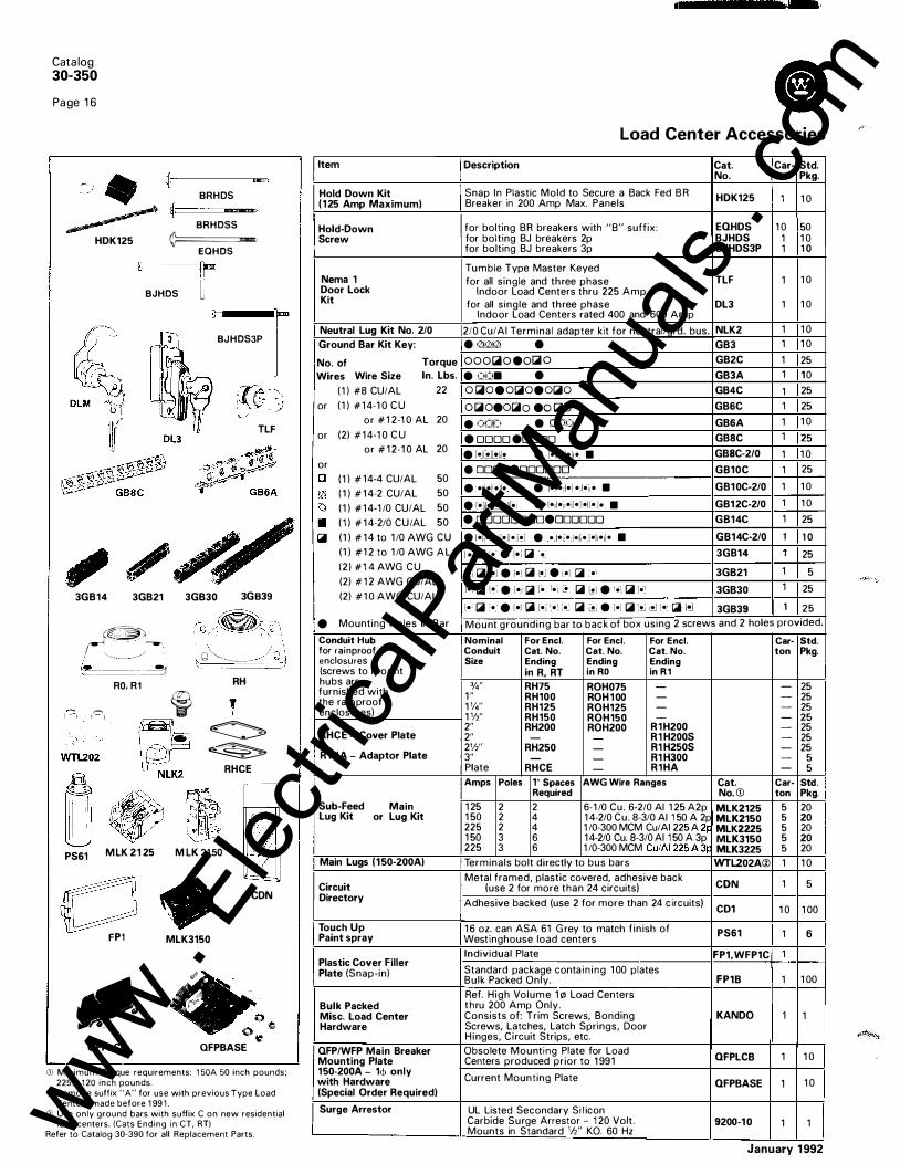
Snap In Plastic Mold to Secure a Back Fed BR HDK125 1 10 Breaker in 200 Amp Max. Panels
for bolting BR breakers with "B" suffix: EQHDS 10 50 for bolting BJ breakers 2p BJHDS 1 10 for bolting BJ breakers 3p BJHDS3P 1 1 0
Tumble Type Master Keyed for all single and three phase
Indoor Load Centers thru 225 Amp TLF 1 10
for all single and three phase DL3 1 10 Indoor Load Centers rated 400 and 600 Amp
210 Cu/AI Terminal adapter kit for neutral/grd. bus. NLK2 1 10 • Qjr2Jr2J • GB3 1 10 OOOIOiiO eOWiii O GB2C 1 25 • Qt:J. • GB3A 1 10 o iOiloeoWilloeoWillo GB4C 1 25 o WilloeoWillo eo Willa GB6C 1 25 e OtJD • 000 GB6A 1 10 e oooo eoooo GB8C 1 25 e r·J�lloJI• • l•ll•il•li• • GBSC-2/0 1 10 • ooooeoooooo GB10C 1 25 e •I•F•il• e 1•1:•:1•! •Jl•n• • GB10C-210 1 10 e r•JI•l�l•ll•i • I•JI•i !•il•:l•ll•l• • GB12C-2/0 1 10 e DDDDDDDDeDDDDDD GB14C 1 25 • l•lj• JI•il•ll•:i•i • • ,[ •1•• ,je[;e ,[ •lt•Jl• • GB14C-210 1 1 0
I • Will '.•: e l•l Will •: 3GB14 1 25 ,•J WI I•J e I•! Will i•J e i•l Will :• ' 3GB21 1 5 I• I Will 1•: e l•i Will I• l•i � Will i!l e '•i Will lo1 3GB30 1 25 l• Will :• . • [•I Will l•i 1,•\ l•� WI �j • l•i Will :!J I� [or Will [oj 3GB39 1 25 Mount grounding bar to back of box using 2 screws and 2 holes provided. Nominal For Encl. For Encl. For Encl. Car- Std. Conduit Cat. No. Cat. No. Cat. No. ton Pkg. Size Ending Ending Ending
in R, RT in RO in R1
%" RH75 ROH075 - - 25 1" RH100 ROH 1 00 - - 25 1%'' RH125 ROH125 - - 25 1W' RH150 ROH150 - - 25 2" RH200 ROH200 R1H200 - 25 2" - - R1 H200S - 25 2W' RH250 - R1 H250S - 25 3" - - R1 H300 - 5 Plate RHCE - R1HA - 5 Amps Poles 1" Spaces AWG Wire Ranges Cat. Car- Std .
Required No. CD ton Pkg.
125 2 2 6-1/0 Cu. 6-2/0 AI 125 A2p MLK2125 5 20 150 2 4 14-2/0 Cu. 8-3/0 AI 1 50 A 2p MLK2150 5 20 225 2 4 1/0-300 MCM Cu/AI 225 A �p MLK2225 5 20 150 3 6 14-2/0 Cu. 8-3/0 Al 1 50 A 3p MLK3150 5 20 225 3 6 1/0-300 MCM Cu/AI 225A 3p MLK3225 5 20 Terminals bolt directly to bus bars WTL202A® 1 10 Metal framed, plastic covered, adhesive back
CON 1 5 (use 2 for more than 24 circuits) Adhesive backed (use 2 for more than 24 circuits)
CD1 10 100 16 oz. can ASA 61 Grey to match fin ish of PS61 1 6 Westinghouse load centers Individual Plate FP1,WFP1C 1 Standard package conta in ing 100 plates Bulk Packed Only. FP1B 1 100 Ref. High Volume 1!21 Load Centers thru 200 Amp Only. Consists of: Trim Screws, Bonding Screws, Latches, Latch Springs, Door Hinges, Circuit Strips, etc.
KANDO 1 1
Obsolete Mounting Plate for Load QFPLCB 1 10 Centers produced prior to 1991
Current Mounting Plate QFPBASE 1 10
UL Listed Secondary Silicon Carbide Surge Arrestor - 1 20 Volt. 9200-10 Mounts in Standard 'li' KO. 60 Hz
1 1
January 1992
www . El
ectric
alPar
tMan
uals
. com

Residential Loadcenters I ndoor N E MA 1
Box Dimensions Style H w D
1 C 8% 4% 27/s 2C 14V• 6% 3V2 3C 1 2 1 1 31/2 4C 1 5 1 1 3V, 5C 1 6% 1 4% 37/s 6C 1 8% 1 4% 37/s 7C 20% 1 4% 3'l's 8C 23 1 4% 3'/s 9C 27 14% 37/s
10C 33 14% 37/s 1 1 C 37 1 4% 37/s
Residential Loadcenters Rainproof N E MA 3R
Box Dimensions Style H w D
1 8% 5 3V, 1 R g13;,. 5 3% 2R 141/4 6% 3'1, 3R 1 2 1 1 3'/, 4R 1 5 1 1 3'!, 5R 1 8'/. 1 4'!, 4'!, 6R 20% 1 4'/, 4'!, 7R 23 14'/, 4'/, 8R 29 1411, 4'/, 9R 33 1 4'1, 4'/,
10R 37 14'!, 41/,
:P--o 1-1 '/• KO and @ -----;:- AH hub provision - ---"--1 '
Mountm�/�ole T for 1 Q, 3 Screw I "" @ ! 'h·V•
@ r-�r-rl 1f2-3/4 0 'h-3/4 0 o 5/,s
@ � '/2·1 -1V. '/2·¥•·1
Box 1
Knockouts Letter A B
s;,. % . . . . . .
Conduit . . . . . . Size . . . . . .
� ® ® © © 0) ® ® ®
(0:': ® ® '------=----
Box 1C
"CB
0
0 0 0 ; (E)
Box 1R
8 ®® ®@
® © ®® 0
Catalog 30-350
Page 1 7
Residentia l Load Center Dimensions and Knockout Data I n door N E MA 1 a n d N E MA 3R E nclosu res
c D E F
'!, % % %
% % % . . . . . . 1 1 . . . . . . . . . 1 ';. . . .
® � ® · ® 0 0 © 0 © © © © ® © 0 0 0
®00® © ®® Box 2C
�
© 0 0 0
� 0 � ::£) Box 2R
®cW® @88°®@ @® ®®® ®®®@ 8@® 08
0 8® ® 0 ®8 ®® ®®®8®®®© ® ® N 8 0 @ ® ' © ' ® ©
H H-1 I J K M N p 0 s T-1
% % % 1 1 1 1/4 1 ';. 1 '!, 1 '!, 2 211,
1 1 1 . . . 1 ';. 1 1/, 1 1/, 2 2 2'1, 3
1';. 1 '/, 1 1/4 . . . 1 1/, 2 2 2'1, 2'/, 3 31/,
. . . . . . 1 '/, . . . . . . 211, 3
'F;i:F)@'F; 0 (00"2·>0 ® 0 0 0
CD @ 0 0 G_:, c�
(i) 0 © ·:D
0 0 0 0 0 0 e; o 0 0 i)
,ti;
Box 3C
@ HUB
G 0 0 ® ® ® 0 0 ® ® 0 ® 8 ®® 0 0 ® 0 ®
Box 4R
8 ®® © ®
® @0 @ 0 8
0 c; (,)
@
G 0
8
:i Fi, ', , ., , ,,
_0_@_
0 •D
0 s�00 Box 3R
0 0�c/!'
ci) ��
0 ,i ((,) 0 '� , ,
,., i ) ·� .;-.;;;- i'
Box 4C
0 0 c�
,C) 0
8©©® 8 8 © ® 8 ® © © 0 N ® © @ ® ® ® © @
Box SC, 6C, 7C, SC, 9C, 1 0C, 1 1 C Box 5R, 6R, 7R, SR, 9R, 1 0R
Note: R Hub Hole Accept 3 - RH075 i'14'1. RH1 00 (1"), RH1 25 (1 114'1. RH1 50 ( 1 11{), RH200 (2")
January 1992
www . El
ectric
alPar
tMan
uals
. com

Catalog 30-350
Page 1 8
Load Center Dimensions a n d Knockout Data I n door N E M A 1 E n c l osu res
Commercial Load Centers Knockouts I ndoor NEMA 1 Letter A B c D E F G H I J Box Dimensions % 3/s ';, 9/1 6 3/4 'Ia 1 1 ';. 1 '1, 2 Style H w D
1 7 4% 21%, Conduit
K L
';, ';4
% ';,
Cl M N 0 p Q R s T u v W X y z A1 A2 A3 A4 % ';, ';, % ,h % % % % 1 1 1 1';. 1 '1. 1 '1, 2 2';, C1
0 c: �
';, % 1 2 2 1 1 1 1 1 ';. 1 1/4 1 1;. 1 11, 1 '1, 2 2';, 3 Q_
:;;; 2 1 0% 6 21%, Size . . . % % 1 1 114 1 '14 211, . 1 114 1 11, 1 ';. 1 11, 1 11, 1 '1, 2 2 2';, 3 3'12 �· 3 1 5% 6'/. 31 3/1 6 4 14% 1 2Vs 3% 5 1 8 1 4% 3'1s 6 20 14% 37/s 7 22 14% 37/s 8 24 14% 37/s 9 26 14% 3'1s 1 0 28 14% 37/s 1 1 30 14% 3'1s 1 2 32 14% 3'1s 13 36 14% 37/s 14 38 14% 37/s 1 4A 37 143/s 5% 1 5 22V2 9% 5% 1 5A 29 9V2 4V, 16 44 1 67132 5V16
1 7 54 1 65/32 5V1B 1 8 38 1 6%2 6V4 19 44 1 65/32 6% 20 44 1 65/32 6V4 21 39 1 67/32 65/16 22 54 1 6'132 65116 23 60112 1 67/n 65/16 24 66V2 1 67132 65f16
8 8 8 8 8
8 8 8j 8 8
I
Box 15, 15A
... . . . . . . . . . . . . t
��® 0 0 ® c o,c� A4 0 00 A4 I 0 ® \ o......_ 0 cf 0 0 c
® 0 0 cg)" 0 0® ® ® Lo 8 ®0 o 0
C [(s)o(s) ®o 0 o/c ·�o ®8® A4 A4 .:4
Box 1 Box 2 Box 3
J. ���@�(0 /c k0G� � 0® ®G) I� 0 8 8 8 8 /0 c 1 I c
� 8 G5 0® � 0�®�®�
� c Box 5, 6, 7, 8, 9, 1 0, 1 1 , 1 2, 13, 1 4
() (c) (i) ' ® ® ®
0)
0® ®0®®®0 @ N ® B 08 ® 0®� CJ0® 00
() () j(;;)®e (00® CfiJ [0®�® ' ®� 0 (i) ® ®®® Box 14A
G 8(8) ®
(i) ® 0)
G G G 8 c · Lann_nGG @�I A3 A2
Box 1 6, 1 7, 1 8, 1 9, 20, 21
1 '1, . 2 2 . . . 211, . . . . .. . 2112 . . . . . . . . . .. . .. . �SWA ® u Jlif
0 ® G)® ®®
®® ® ® ® ® ®®®® ��®�$
Box 4
K
GG�l c
8 G 8 G
I I I I I I I I I I �0 0 0 ;�
C ®� A3 A2
'K I Box 22, 23, 24 I
I ' I I I I I -.)
January 1992
www . El
ectric
alPar
tMan
uals
. com

Commercial load Centers Knockouts Rainproof NEMA 3R letter � B c D E Box Dimensions
';4 ';, % ';, % Style H w D % 1
23 1 3 647/64 3' %, Conduit 24 1 5% 61/4 4 Size
25 1 51/1 6 1 2% 4 26 1 81/1 6 1 4% 41/1 6 27 20 1/1 ; 1 4% 41/1 6 28 22 1/1 6 1 4% 41/1 6 ,------------29 22 1/1 6 1 4% 41/1 6 0 0 30 22 1/1 6 1 4% 41/1 6 3 1 241/1 6 1 4% 41/1 6 32 261/1 6 1 4% 41/1 6 33 28 1/1 6 1 4% 41/1 6 34 30 1/1 6 1 4% 41/1 6 ©® © ®© 0 ©0)� 35 32 1/1 6 1 4% 41/1 6 � 0
<g;8: 36 36 1/1 6 1 4% 41/1 6 T � 37 381/1 6 1 4% 41/1 6 38 241/1 6 1 4% 41/1 6 Box 23 Box 24 39 261/1 6 1 4% 41/1 6 40 22112 95fs 5% 40A ·29 95fs 5% 4 1 f44v,6 1 65/1 6 5Va 0 0 42 38 1 65/16 6% 43 44 1 65/16 6% 44 44 1 65f16 6% 45 54V16 1 65/16 5Va 46 p4 1 65/16 .6% 47 669/16 1 65/1 6 6%
Hub Provision 0 8CD 8 0
Gli�CD: Hub Size Type T ype Hub A
l u %, 1, 1 V4, 1 V,, 2 ROH Box 29
l v 2, 2112, 3 R 1 H
LR '%, 1 , 1 %, l V2, 2, 2 V, RH :0
0
0 80 8 0 8 0 8 0 8 �®�� A 8 8 Box 38, 39
Box 40, 40A NOTE: "R" Hale accepts hubs - RH
Catalog 30-350
Page 1 9
Load Center Di mensions a n d Knockout Data Rai n p roof NEMA 3R E n c l osu res
F G H I J K l M N 0 p 0 R s T u v % ';, ';, % 1 1 ';. 1 11, 2 211, ';4 % 1 ';. '" '" 1 1 0 0 0 " :r: :r: ';, 3;4 1 1 1 1/4
1 1/2 2 21/2 3 1 1 1 V4 , ,h , ,;4 ro ro o-z 0 Ul
% 1 1 1/4 1 ';4 1 11, 2 21/2 3 31h 1 1/4 1 1/4 1 11, 2 1 1/2 0 �:: .,:_:! M
1 11, 1 11, 2 211, 2 211,
0 0 8
0 0 T 0 0 0 0 0 � 0 0 0 � ®®®®Gf®®®® ©®®® a @®® © ��: ��: A A
Box 25 Box 26, 28 Box 27
0 0
0 8CD 8 0 0 8CD 8 0 �«CD� ��CD�
A A Box 30, 33, 36 Box 31, 32, 34, 35, 37
0 � 0 0
8 0 8 8 8 8 8 8 8 8 0W8 8 0W8 8 <tfoq;o " M <tfoq;o " M
B B
Box 41, 43, 44, 45, 46, 47 Box 42
" U" Hole accepts hubs - ROH075 (3/4') , ROH 100 (1"), ROH 1 25 ( 1 '14'), ROH150 ( 1 W'i, ROH200 12'1 "V" Hole accepts hubs - RIH200 (2 ), R I H250 (2'12'), R IH300 (3')
January 1992
www . El
ectric
alPar
tMan
uals
. com

Catalog 30-350
Page 20
Meter Breaker Panels 1 Ph ase, 3 W i re 1 20/240 Volts AC R a i n p roof N E MA 3 R
WMB101224S WMB2048SLR
WMB Family
WMB101224S WMB2048SLB (Covers Removed)
Product Description Service entrance equ ipment that combi nes meter mounting and a c i rcuit breaker distribution section in a ra inproof enclosure. In addition to residentia l i nsta l lations, Westinghouse meter-breakers are equal ly appl icable for ru ral service entrance, mobile homes, and for temporary power on construction sites. They are Listed by Underwriters Laboratories Inc., File No. E52977.
Westing house meter sockets conform to UL Specification 41 4 and AEIC-EEI-NEMA sta ndards (MSJ-7). Neutrals are factory bonded to the enclosure. These meter-breaker combi nations fulfi l l EUSERC Util ity requ i rements except as noted.
Plated a luminum bussi ng accepts the Westinghouse system of p lug-on c i rcuit breakers. Un its are rated 1 0,000 AIC. G round bars are avai lable for fie l d i nstal lation.
Product Specifications Rati ngs Sing le phase, 3 wire, 1 20/240 volts AC; 1 00 through 200 a mpere main breaker and main lug types; 1 0,000 am peres RMS symmetrical short ci rcuit rati ng.
Features • New i nterior accepts Westi nghouse c i rcuit
breaker Types BR, BD and G FCB. • Overhead or u nderg rou nd service. • Meets latest NEC wi re bendi ng space
requ i rements. • Fifth jaw can be i nstal led in the 3 o'clock
or 9 o'clock posit ion. • Slotted sea l ing screws at hub with sea l ing
position provided. • Semi-flush nail f lange. • Meter mounting and u nderg round pu l l
sections are uti l ity sea lable. • Meter socket r ing landing wil l accept lock
ing security rings.
• Surface u n its are supplied with mounting tabs.
• Molded bus su pports assure r ig id construction and security of bus bars.
• Flat dead front and sealable pu l l sectio n conta in captive screws.
• Lockable distri bution cover. Dead front has a l ifti ng handle.
• Raised distri bution panel and i n creased wi reway space speed i nstal lation and wiring of branch c i rcuit breakers.
1 00 and 125 Ampere Devices • Center feed main breaker h igh l ig hts this
a l l-new distribution section . Even d istribution of load and cooler operat ing a m bient i ncrease component rel iab i l ity.
• Compact enclosure is l ight in weig ht for easy i nstal lation.
January 1992
www . El
ectric
alPar
tMan
uals
. com

Cl Cata log 30-350
Page 2 1
Meter Breaker Panels 1 Ph ase, 3 W i re 1 20/240 Volts AC
R a i n p roof N E MA 3 R
WMB121224S
WMB2024SN WML20612SN WMB202040F
Single Phase, 3-Wire-120/240 Volts AC-1 0,000 AIC NEMA 3R, Rainproof, with RH Hub Provisions-Overhead or Underground Service Main I Branch Ci rcuit I Semi-Flush I Surface Ampere I Brea-ker Provisions ---------+--Rating Max. 1 -Pole 1 - Max. 2-Pole Catalog I Cat�l;;g _ _ , 1 " C/B 1 '12'' C/B I 1 " C/B I '12'' C/B Number ____ _,_ _ _
N_umb_e_r _____ _
Main Breaker Factory Installed
Wiring Diagram Figu re Number
' �:: . I �: I :: I :- ,---I ��-:�-- --- -_ '_,-:::�����: __ : __ --+_:_:_
:_�����:i
--·_· · ----+-·
1:: l ':u � ': .1
2� :MB202040F · f :::��::���
2 2 3
I 4 c-3-00 32 ' 40 1 1 5 2 0
I -WMB203240S 0
c-3-25 20 1 40 1 5 20 . WMB222040F0 IIIVMB222040S0
- -1 0 3
WMB202040S
Knockout Figure Number Semi- I Surface Flush
2 3 --2 3 5 4
- I 6 - 1 1 1 - -
·-·
WMB202040S IAII Covers Off)
[ Line 1 Wire Range
# 14- 1 /0 Cu/AI #14- 1 /0 Cu/AI #6-250 MCM Cu/AI #6-250 MCM Cu/AI
I #6-250 MCM Cu/AI #6-300 MCM Cu/AI --
Order Main Breaker Separately
�0 1 -- i - I 1 t � I' -WMB1224FN ,._W_M_B_1_0_2-RN
_®_® ___
_ -_--,
�-
1- ---,-
1
_------�--------j
125 4 I - . 2 '. 2 - 'I WMB1224SN � � . WMB1224SCN® : --+-'---+------------J
���--
��-Pr:isions�- 1
2 �-- - i �MB20FN-@---+1
-:-::����
S�--
R
-CD_1_0 ___ -tl --; __ -.:_
-+tl---7---l-
1 -�/O Cu/AI _ 3A #14-1 /0 Cu/AI 9
200 � ! - j 2 . 2 WMB2024FN I WMB2024SN 8 7A I '
9 8 8 8
#14-1 /0 Cu/AI 1 #6-250 MCM Cu/AI #6-250 MCM Cu/AI
1 #6-250 MCM Cu/AI � ·
· '':" ' j"''''""''"I'-T-f--z__ · = ____ j ;::��::s�: f �
4
= ·-
2oo 4 � . �---t-T- / - _ I WMB2048SLRCD-'®:__ __ ___;_t_:_ __ --f----+--=----+-"-.:__:_'--'__::-----l 200 20 40 J 10 20 - I WMB202040RCD@ i 3
8 #6-250 MCM Cu/AI
I 8 #6-250 MCM Cu/AI
Main Lug Only 200 . 1 1 2 - I - -- I 6 -r=- I _-____ ----�IJI.IIVIL20612SN® I 9 , -
CD Single cover Florida design. GJ Overhead Feed Only.
Accessories
@ Compact design. Does not meet EUSERC requirements. ® Provisions for 1 WFP•QFP breaker to 200A.
---- · ---Catalog Number Description
� Does not meet EUSERC requirements. ® Underground Feed Only.
4A #6-250 MCM Cu/AI
I 1 0� #6-250 MCM Cu/AI (jJ Availability to be announced.
I Carton Standard Pkg. WMB5J 5th Jaw Assembly For Meter Socket enclosu res 3 or 9 o'clock position _______ _________ .;..I, _1 __ -+_5 ____ ----J WMBBLK1 Barrel Lock Kit WMBBLK2 Barrel Lock Kit
For WMB Meter Socket enclosures - 1 - 21 in. enclosure 2 - 27 in. enclosure
'--W_M_B_B_L_K_3_�Barrel Locl<__l5i_t____L__ ____ __ _ Order BR, BRH main tenant breakers from pages 4, 5. Order WFP, WFPH main tenant breakers from page 4, without "T" suffix.
January 1992
3 - 36 in. enclosure ---
- -----If separate Ground Bus is requ i red order WM B24G B, WMB9GB. www .
Elec
tricalP
artM
anua
ls . c
om

Catalog 30-350
Page 22
2 ' BONDED NEUTRAL Overhead Feed Only
Fig. 1
A
A B
N
BONDED NEUTRAL
Fig. 8
BO� NEU!HAL l Fig. 2
A
Fig. 5
Flg. 9
Fig. 3
N
NEUTRAL BO��
1 2 3 4
Fig. 6
BONDED NEUTRAL
I
Meter Breaker Panel W i ri ng D i a g ra m s, D i m e n s i o n s , W e i g hts
' b
' 8 BONDED NEUTRAL
20
JO
r - - - - - - -, --��-+-r---, I
Fig. 4
N IOii>-----------<>Qe
BONDED NEUTRAL
Fig. 7
I Omitted � For SLR I Design I
Type BR, BRH
Only
Catalog Dimensions-Inches Carton Number Height Width Depth Wt.
lbs. WMB102RN 1 97/a 7V, 4V• 11 WMB101 224F&S 20% 14% 4% 26 WMB121 224F&S 20% 14% 4% 26 WMB1224FN&SN 20% 14Va 4% 26 WMB1224SCN, SCR 123fa 14Va 4% 16 WMB202040S&F, R 36 14Va 5% 47 WMB222040F, 5 36% 14% 5% 49 WMB20SN&FN 27Va 14% 5% 31 WMB2024SN&FN 27Va 14% 5% 31 WMB2048SLB 27Va 14% 5% 31 WML20612SN 30V. 14Va 5% 34 WMB20SR 27Va 1 4Va 5% 31
Underground Feed Only WMB2024SR 27Va 14% 5% 31 WMB2048SLR 27Va 14% 5% 31
Fig. 10 WMB203240S 30V. 22V• 6 55
January 1992
www . El
ectric
alPar
tMan
uals
. com

Fig. 1
.��- ' ----.-1 l0� - ·�· r -
I n
I I n
l_�
L_
January 1992
Q i I i
Fig. 5
,, _ ___________..,
Fig. 8
-��0 LL________ -.-I I
I I I I I I I I I I I I
0 _ll
F i g . 2
f----- • .: I C I T ,- 1 :o: LL__ ---.
Fig. 6
� _, , ,__ --1 ooo 1· 1 0 0 cl_
I f
I t
I 1 1 ' I' 0 ,2--J l
_L __ _ 9 9r F i g . 9
Code Conduit S 1ze-lnches
A B '/J C liz-3/a 0 1/r----Jfa-----1
E 1/z-3/4-----1-----1 1/o
Cata log 30-350
Page 23
Meter Breaker Panels D i m e n s i o n s a n d Knockout Data
F i g . 3
Note: Fig. 3A same as Fig. 3 but 2 Hub openings top.
Fig. 7
1-------- ' '· , s ---------..J � -T
-lT I I I I 1 ' 1 '
I '0' 1· • -- 0 0 � �
[Code _
CondUit $1ze-lnches [ l 1-----1 1/4----- 1 1/z-2
M 1 ' 14-----l 'h---2 N 1%-1'h--2-2'h p 1 1fz-2-2'h Q 1 1/z------2-21/r--3 R 2
I I I I i ' I I
Fig. 4
Note: Fig. 4A same as Fig. 4 but 2 Hub openings top.
Fig . 7A
Fig. 1 1
www . El
ectric
alPar
tMan
uals
. com

Catalog 30-350
Page 24
Residential House Panel - 400 Amp - Type HP 1 Phase, 3 W i re 1 20/240 Volts AC R a i n p roof N E MA 3 R - P l u g I n Socket
Features :
• UL Listed, F i le E21 683
• Service Entrance Equ ipment
• Meets EUSERC Requirements
• Plug-In 400 Amp Meter Socket (320 A Conti nuous)
• Underg round Con nection
HP402442
(Covers Removed)
S i n g l e Phase, 3 W i re - 1 20/240 Vo lts AC - 1 0,000 AIC N E MA 3R, R a i n p roof, 400 Am p, R i ng Type P l u g In Socket
Main Main Maximum Amp I Catalog Ampere Breaker Secondary Surface Mtd. Rating Rating Main
(Field Installed)
400 400 - · HP402442 400 200 , 200CD : HP402440S 400 200 400 ! 400 400 200
I 200(]) I , -
: 200(])
0: Order Type WFP OFP Sub Main Breakers from page 34. W 22,000 AIC Rated using WFPH Mains.
Accessory item Catalog HPSFK available to convert Surface Mounting to Semi-Flush Mounting. All catalogs have underground NEMA Stud Landings for either Compression or Mechanical Lugs.
HP402440SH ® HP40 HP40S
Branch Circuit Breaker Provisions
Maximum I Maximum 1 -Pole Spaces '12 Size Spaces
24 42 24 ' 40 24 !, 40 - -
- -
HP402442
I Dimensions - l
"
:�hes
Height Width I 401/4 30
1 40'1• 30 i 401/4 30 "-i 401/4 30 i 401/4 30
8
Carton Weight
Depth (lbs)
8V2 1 50 8V2 125 8V2 125 8V2 120 8V2 110
January 1992
www . El
ectric
alPar
tMan
uals
. com

FIELO INSTALt.EO 2:00A�P SERVICE DISCONNECT
HP40S
HP40
AMPS 400 I SERVICE ) _ _ J DISCONNECT
200A�I' SERVICE DISCONNECT FACTORT INSTALLED
FIELD INSTALLED 200A�P SERVICE DISCONNECT
�=:: ,---..,. _ 2:1 ,---..,.- 29
- -c::=::= �� ,---..,._ 31 ,---... _ 32
�' r�- -c::=::=:! ,---..._ 3�
January 1992
,-....._ 36
-{_.::::=� :J----4:�=!�
HP402440SH
•
Left Cover
1 '/4" c::::::J TERMINATING
� e"'"""l 22"
Dimensional Information
EQUIPioiENT GROIJN�NG TERioiiNALS
H I 1\-� . ' ; '-'� (
I
Catalog 30-350
Page 25
Type HP, 400 Amp House Panel W i ri n g Schem atics/D i m e ns i o n a l I nfo rmation
400 AMPERE SINGLE PHASE PLUG IN METER BASE
HP402442 (Typical Assembly)
(' "TYPICAL
Hinged Door
L _ _ j
T 6 5 " I 0 1oo o o o o o o I coo, Condull S11e - Inches
8 c I 75 I 75 I r ::s 15 p 15 ' 2 5 Q 2 5 - ) 3 5 4 j__
EOUIPI.IENT GROIJNOING lERt.IINALS
I �� �l . ' .
LINE
, _ ,--..... _
�=::::::r , _--------.
1 0 - �
�� -::::::]--13-.....-, 1<4 -.....-,
::=�]-17-� 16 - ,.--..,
FIELD INSTALLED 200A�P SERVICE DISCONNECT
��=�J----'-C
&oNOEO NEUTR.t.L
EOUIPt.IENT GROIJN�NG TERMINALS
HP402442 HP402440S www . El
ectric
alPar
tMan
uals
. com

Catalog 30-350
Page 26
WM Modular Meteri ng M a i n Se rvice C u b i c l es
WMB8 WMF4
Complete Assembly
WM31 2 WM320
Components of a Meter Center Are
WMF4R
-----... -.
W3MF4B (Cover Removed)
• Main Service Cubicle • Feeder Tenant Breaker • Meter Stacks • Accessories
Main Figure Wall 1 Phase 3 PhaseCI: Carton Dimensions (!nches) Terminal and Circuit Rating p, 35 Mounting
Catalog Catalog WL w H D Neutral Wire Breaker Amps Number Number Lbs. Sizes Per Phase Frame
Main Breaker (Breaker Included)@ @ 400A 1 Indoor WMB4 W3MB4 69 1 6 391/2 8 (2) #3 0-250 MCM KD
2 Outdoor WMB4R W3MB4R 72 1 6 405Js 8
600A 1 Indoor WMB6 W3MB6 82 16 391/2 8 (2) 250-500 MCM LA
2 Outdoor WMB6R W3MB6R 1 05 1 6 405fs 8
800A 3 Indoor WMBB W3MB8 1 00 20 49 81/2 (2) 500-750 MCM MA Outdoor WMBBR W3MBBR 1 20 20 50 81/2
1 000A 3 Indoor WMB10 W3MB10 1 40 20 49 8112 (4) #3 0-500 MCM NB Outdoor WMB10R W3MB10R 1 56 20 50 8112
1 200A 3 Indoor WMB12 W3MB12 1 40 20 49 8112 ( 4) #310-500 MCM NB Outdoor WMB12R W3MB12R 1 56 20 50 8112
1 600A 4 Indoor - - - - - - (4) #1 10-750 MCM PBF Outdoor WMB16R W3MB16R 4 1 0 327/a 69 1 61/4
Fusible Switch (T-Type Fuses not included)@ @ 400A 1 Indoor WMF4 W3MF4 65 1 6 391/2 8 (2) #3'0-500 MCM
2 Outdoor WMF4R W3MF4R 70 1 6 405fs 8
600A 1 Indoor WMF6 W3MF6 65 1 6 39112 8 (2) #3,0-500 MCM
2 Outdoor WMF6R W3MF6R 70 1 6 405fs 8
800A 3 Indoor WMFB W3MF8 1 1 4 20 49 81/2 (4) 250-350 MCM Cu or Outdoor WMFBR W3MF8R 1 20 20 50 8112 (4) 350-500 MCM AI
1 200A 3 Indoor WMF12 W3MF12 1 1 4 20 49 81/2 (4) 250-350 MCM Cu or Outdoor WMF12R W3MF12R 1 20 20 50 81/2 (4) 350-500 MCM AI
Fusible Switch - Plug In Connected to Westinghouse Bus Duct (T-Type Fuses not included)@ @) 400A 1 Indoor Use 30 W3MF4B 80 1 6 391/2 8 - -
600A 1 Indoor Use 30 W3MF6B 80 1 6 391/2 8 - -
G::: All 3-phase mains require 3-phased bussed stacks. Ct For higher integrated rati ngs see series ratings on
page 27.
@ Main Service cubicles may be applied with either left or right hand Bus Tap sections as requ�red by building layout.
G! Li ne side located on top of unit.
WM meter stacks may only be added to one side of the Fusible Switch. (side opposite the Bus Tap flange) Bus link extensions are installed and hardware is packed with each unit. The rear surface of the Main Service Cubicle aligns with the rear surface of the Bus Tap section.
January 1 992
www . El
ectric
alPar
tMan
uals
. com

W3ETB6R UGMFS6R
Main 1 Phase 3 Phase® Rating Catalog Catalog Amps Number Number
Cable Tap Box (For Either Indoor or Outdoor Use) 200A 5 Outdoor W3ETB2R 45 600A 5 Outdoor W3ETB6R 62 800A 5 Outdoor W3TB8R 65
1 200A 5 Outdoor WTB12R W3TB12R 68 1 600A 5 Outdoor W3TB16R 75
UGM3FS4R (All Covers Removed)
1 05116 18 S3fs 1 6 20 81/2 1 6 43 8112 20 43 81/2 327/s 69 1 61/4
Cata log 30-350
Page 27
WM Modular Metering Main Service C u b ic les
W3TB1 2R
Terminal Torque Sizes Per Phase Ratings
in./lbs.
( 1 ) #1 -300 MCM 275 in./lbs.
(2) #3/0-500 MCM 275 in./lbs.
(2) #1 10-750 MCM 375 in./lbs.
(4) #1 /0-750 MCM 375 in./lbs.
(4) #1 /0-750 MCM 375 in./lbs.
Combination Fusible Switch with Underground Pull Section - Switch Included (T-Type Fuses not included)® 400A 6 Outdoor UGMFS4R UGM3FS4R 1 1 2 1 83;8 451/4 8'14 ( 1 ) NEMA Crimp Type
600A 7 Outdoor UGMFS6R UGM3FS6R 1 63 24 481/2 1 1 112 ( 1 ) NEMA Crimp Type
800A 7 Outdoor UGMFSSR UGM3FS8R 1 65 24 481/2 1 1 1/2 ( 1 ) NEMA Crimp Type
Underground Pull Box (For Either Indoor or Outdoor Use) CD 400A 8 Outdoor UGPB42R UGPB43R 67 1 8 40 7 (2) #4-350 MCM 275 in./lbs.
600A 8 Outdoor UGPB62R UGPB63R 1 03 24 48 1 1 (2) #2-600 MCM 275 in./lbs.
800/1200 Amp 8 Outdoor UGPB122R UGPB123R 136 32318 52 1 13fs (2) #3/0-750 MCM 375 in./lbs.
All main servtce cubicles include both left and nght closure plates. CD Requires additional service cubicle. ® Spacer kit WSSKR required when stacks are mounted on right hand side.
System Short Circuit Rating
WM, W3M, W35M, W37M Series WM Modular Metering
Maximum Available Metering Main Device Tenant Main Loadcenters 1 25A & 200A and branch breakers Short Ci rcuit Current Tap Fusible Circuit 1 0 30 1 0 30 RMS Symmetrical Ampere Box Switch Breaker 240 Volts Ac Meter Position Meter Position
1 25A 200A 1 25A 200A 125A 1 200A 1 25A 1 200A Tenant Tenant Tenant Tenant
WM and W3M Type Modular Metering
1 0,000 1 600 MFS Series MCB Series BR WFP NiA N!A BR, BD, BQ, GFCB BR, BD, BQ, GFCB NIA N/A Amp Max.
22,000 1 600 - - BRH WFPH N!A NIA BR, BD, BQ, GFCB BR, BD, BQ, GFCB N•A NIA Amp Max.
42,000 1 1 200 Amp Max.) - - MCB Series BRH WFPH® N'A N'A BR, BD, BQ, GFCB BR, BDGJ, N'A N!A 1 200 Amp Max. BQ, G FCB
65,000 (400 Amp Max.) - - MCB Series BRH WFPH N'A N;A BR, BD, BQ, GFCB BR, BD, BQ, GFCB N!A N!A 400 Amp Max.
100,000 1600 Amp Max.) - MFS Series - BRH WFPH N.A NIA BR. BD, BQ, GFCB BR, BD, BQ, GFCB N1A NIA 600 Amp Max.
1 00,000 (1 200 Amp Max.) - MFS Series - BRHH - N,A N/A BR, BD, BQ, GFCB - N.'A NIA 1 200 Amp Max.
W35M and W37M Type Modular Metering
10,000 1600 MFS Series MCB Series BR WFP BR WFP BR, BD, BQ, GFCB BR, BD, BQ, GFCB BR, BD, BQ, GFCB BR, BD, BQ, G FCB Amp Max.
22.000 1 600 MFS Series MCB Series BRH WFPH BRH WFPH BR, BD, BQ, GFCB BR, BD, BQ, GFCB BR, BD, BQ, GFCB BR, BD, BQ, G FCB Amp 1 200 Amp Max. Max.
65,000 (400 Amp Max I - - MCB Series BRH WFPH BRH WFPH BR, BD, BQ, GFCB BR, BD, BQ, GFCB BR, BD, BQ, GFCB BR, BD, BQ, GFCB 400 Amp Max. ®
100,000 (600 Amp Max.) - MFS Series - BRH WFPH BRH WFPH BR, BD, BQ, GFCB BR, BD, BQ, GFCB BR, BD, BQ, GFCB BR, BD, BQ, GFCB 600 Amp Max.
N/A - Not Applicable.
January 1992
GJ Applies to BD frame breakers in 1 5A ratings only. ® Applies to 200A WFPH tenant mains only. www . El
ectric
alPar
tMan
uals
. com

Catalog 30-350
Page 28
WM Modular Metering Featu res
Each un it is equipped with a wal l mounting bracket, factory instal led. The bracket engages the mounting channel , fastened to the wal l . One man can easi ly l ift u n it and engage brackets. Un it is supported while permanent fasteners are insta l led.
Mou nti ng channel bracket is fastened to the wal l to support the meter module prior to insta l l i ng the permanent fasteners. One bracket is suppl ied with each meter modu le. Mounting channel brackets i nterlock to form one
Al l un metered conductors are barriered and inaccessible.
�-----·-'
I nsta l latio n i nstructions, horizontal bus attaching hardware, cover screws and necessary labels, and wal l mounting bracket are suppl ied in a hardware package with each u nit.
Meter socket is located d irectly above tenant main position for easy identification of individual apartments. Note slot in meter socket ring landing for manual bypass handle, and KO for manual by-pass 1 0/32 seal ing screw (not supplied).
conti nuous channel for mounting ______ __. ... ---------- Plug-on circuit breakers facil itate instal lation of tenant main devices. Neutral load lug is just above tenant main position.
m u ltiple u nits.
Horizontal bus is rated 800 a m peres, standard, with 1 200 ampere bus avai lab le on special order. Left side has captive bolts to aid in al ig n i ng adjacent u nits. Five holes around bus opening are for screws that help c lose opening and provide surface contact with adjacent u nits for grounding conti nu ity.
The cover p late over the horizontal bus compartment is sealable.
Equipment grounding termi nals provided as standard in a l l un its. Located adjacent to bottom meter socket tenant main positions in a l l meter socket compartments.
Replacement meter socket assembl ies are avai lable 1 25 Amp - Part No. 360-006-02 200 Amp - Part No. 360-006-1 0 Special Order Requi red
Potential (neutral connected) 5th jaw kit for use on 1 20/208 Y network services is factory i nstal led in the 9 o'clock position on 3-� units. An accessory kit is avai lable for use with 1 -� u nits, or 6th jaw requ irements on 3-� units.
� Right •ido hod•o"tal bu• bon> "' extended and slotted to l ine u p with left side b u s of adjacent units. Gaskets around opening are provided on NEMA 3R units. Three bus bars (A, N, B) are provided on 1 -� units; four (A. N, B, C) on 3-� units.
i---------- NEMA 3R devices have no-rust molded circuit breaker covers. Positive cover latching device can be padlocked for additional security.
Bottom endwal ls can be removed for use as templates for "stubbing up." Indoor units have identical pattern in top end wal l . Seal ing brackets wi l l accept utility seals or padlocks for security, if required.
January 1992 www . El
ectric
alPar
tMan
uals
. com

Cl Catalog 30-350
Page 29
WM Modular Metering Stacks Type WM - W3 M S i n g l e Phase Te n a nt Loads
Ring and R i n g l ess Type
WM31 2 Typical Installation WM41 2RRL (Covers off - Ringless)
LIST PRICES AND C ATALOG N U M BERS Number Fig. Ma1n Wall 1 Phase Horizontal Bus 3 Phase Horizontal Bus@ ct Carton Dimensions ( I nches) of Meter p. 36 Bus Mounting Catalog Number Catalog Number Wt. w H D Positions Ampac1ty Lbs.
1 25 Ampere Meter StacksCD - 1 Phase Tenant Load - Ring Type 3 8 800A Indoor WM312 W3M312 65 1 01/a 44 7
800A Outdoor WM312R W3M312R 66 1 01/a 44 7
1 200A® Indoor WM31212 W3M31212 69 1 01fa 44 7
4 9 800A Indoor WM412 W3M412AB 72 1 01/a 56 7 W3M412BC W3M41 2AC
800A Outdoor WM412R W3M412RAB 72 10 1/a 56 7 W3M412RBC W3M412RAC
1 200A® Indoor WM41212 W3M412AB12 76 1 01/a 56 7 W3M412BC12 W3M412AC1 2
5 1 0 800A Indoor WM512 W3M512AB 85 1 01/a 67 7 W3M512BC W3M51 2AC
800A Outdoor WM512R W3M512RAB 89 1 01/a 67 7 W3M512RBC W3M512RAC
1 25 Ampere Meter StacksCD - 1 Phase Tenant Load - Ringless Type 3 8 800A Outdoor WM312RRL W3M312RRL 69 1 01/a 44 7
4 9 800A Outdoor WM412RRL W3412RABRL 72 10 1/a 56 7 W3412RBCRL W3412RACRL
200 Ampere Meter Stacks CD ® 1 Phase Tenant Load - Ring Type 3 1 1 800A I ndoor WM320 W3M320 72 1 23fa 5 1 7
800A Outdoor WM320R W3M320R 74 1 23/a 51 7
1 200A® Indoor WM32012 W3M32012 79 1 23fa 5 1 7
4 1 2 800A Indoor WM420 W3M420AB 86 1 23fa 67 7 W3M420BC W3M420AC
800A Outdoor WM420R W3M420RAB 89 1 23fa 67 7 W3M420RBC W3M420RAC
1 200A® Indoor WM42012 W3M420AB1 2 94 1 23/a 67 7 W3M420BC1 2 W3M420AC1 2
200 Ampere Meter Stacks CD® - 1 Phase Tenant Load - Ring less Type 3 1 1 800A Outdoor WM320RRL W3M320RRL 74 1 23fa 51 7
4 1 2 800A Outdoor WM420RRL - 89 1 23/a 67 7
CD Order Tenant Breakers separately. See page 34. 0 3 Phase 4 wire stacks are factory phase balanced and
include 5th Jaw mounted i n 9:00 position.
0 See phase balancing chart (page 36 to insure proper phasing of total l ine-up. (Req u i red for 3-phase mains.)
® Refer to special b reakers (page 34) when tenant mains are rated 1 00 amps or less.
@) Copper horizontal bus.
January 1992 www . El
ectric
alPar
tMan
uals
. com

Catalog 30-350
Page 30
WM Modu lar Meteri ng C o m m erci a l M eter Stacks with Lever By-Pass R i n g l ess Type W35, W37
Ratings • 1 20/208 Volts AC, 3 phase 4
w i re ; or 240 Volts AC, 3 phase, 3 w i re Delta. Suitable to r use on 1 20/240 Volts AC, 1 phase, 3 wi re systems.
• 1 200 ampere copper horizontal bus is stand ard .
• Sockets have 200 ampere conti nuous rat ings and use Type WFP tenant mains .
• 1 0 , 000 AIC i nterrupt ing rat ing is standard .
Features • 3 phase , 4 w i re meter stacks
with 7 jaw D u ncan HQ7 and 1 phase, 3 w i re with 5 jaw Duncan HQ5 meter sockets .
• 1 , 2 , 3 or 4 posit ion stacks with 3-pole ten ant mains , and 2 and 3 pos it ion stacks with 2-pole tenant mains .
�-----·-·
Cl
• A l l devices su itable fo r indoor o r outdoor use.
• A l l u n its connect to existi ng meter ing main devices (W3 M B a n d W3 M F series) a n d meter stacks with 3 phase horizontal bus ser ies .
W37M1 20R W37M120R (Without Covers)
W37M1 40R (Covers Removed)
W37M420R
• A l l u n its UL Listed . • Meter socket covers are
r ing less type. Each socket has a separate cover p late which is removable without d i stu rb ing other cover plates . Each cover plate h as barrel lock and pad lock p rovisions and is capab l e of being sealed with wi re seal s .
• A s ing le cover p late covers a l l tenant mains and i s removable without d i sturb ing meter cover p lates . Each tenant main c i rcu i t b reaker handle is padlockable
• All u n its can be bussed tog ether with type W3M or WM stac ks.
Commercial Meter StacksG) - 1 Phase Tenant Load - Ringless Type Duncan Type HQS 200 Amp Sockets with Lever Bypass - Outdoor
Number of Wiring Main 3 Phase Honzontal Bus@ Carton Meter Figure Bus Catalog Number WI. Positions Number Ampac1ty Lbs.
2 1 1 200A W35M220RAB 1 24 3 2 1 200A W35M320R 1 39
Commercial Meter StacksG) - 3 Phase Tenant Load - Ringless Type Duncan Type HQ7 200 Amp Sockets with Lever Bypass - Outdoor
Number of Wiring Main 3 Phase Honzontal Bus@ Carton Meter Figure Bus Catalog Number Wt. Positions Number Ampacity Lbs.
1 3 1 200A W37M120R 1 09 2 4 1 200A W37M220R 1 45 3 6 1 200A W37M320R 1 98 4 5 1 200A W37M420R 2 1 5
Commercial Meter StacksG:l - 3 Phase Tenant Load - Ringless Type Duncan 400 Amp Sockets with Lever Bypass - Outdoor®
Number of Wiring Main 3 Phase Horizontal Bus@ Meter Figure Bus Catalog Number Positions Number Ampacity
1 3 1 200A W37M140R
CD Order main tenant breakers separately, page 34. ® 400 amp socket rating. Order DK breaker separately. @ 253/16" from bottom of enclosure to C L of buss. ® Use main service cubicles from pages 26, 27.
Carton Wt. Lbs.
1 1 9
Dimensions@ ( I nches( w H D 1 9 40 85/1 6 1 9 501/2 85116
Dimensions@ (Inches)
w H D 1 9 40 85116 1 9 40 85/16 1 9 55112 85/16 1 9 71 85/16
Dimensions@ (Inches) w I H I D 1 9 I 40 1 as;,s
January 1992 www . El
ectric
alPar
tMan
uals
. com
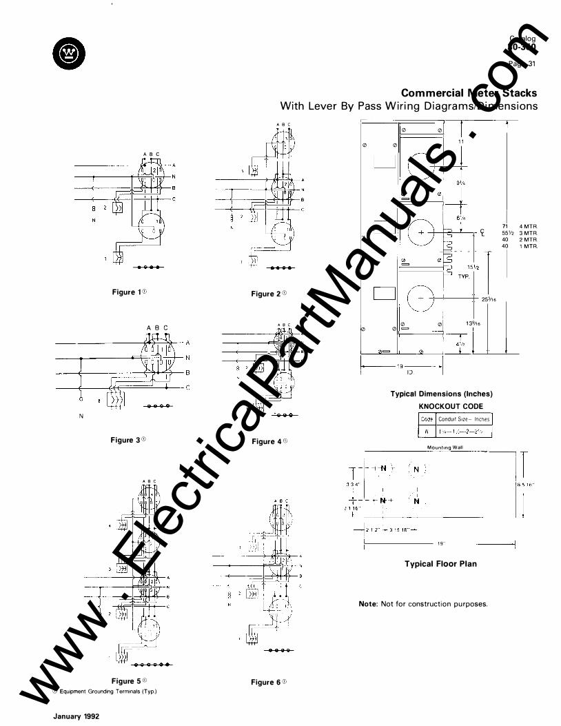
A B C
----�-------F��·l�+- N
=t=��: N
• Q 8 8
Figure 1 CD
A 8 C
N
Figure 3 CD
A 8 C
Figure S CD CD Equipment Grounding Terminals (Typ.)
January 1992
Catalog 30-350
Page 31
Com mercial Meter Stacks With Leve r By Pass W i ri ng D i a g ra m s/Di mensi ons
A 8 C
Figure 2 CD
A 8 C
Figure 4 CD
Figure 6 CD
0
0
0 0
0 1 1
CJ 0 =
<t . . :.,. l TYP.
253/1 6
0 0 1 39/1 6 0 = I
Typical Dimensions (Inches)
KNOCKOUT CODE
Conduit S1ze- Inches
Mountmg Wall
I 71 551/2 40 40
1 9 . . --------------
Typical Floor Plan
Note: Not for construction pu rposes.
4 MTR. 3 MTR. 2 MTR. 1 MTR .
www . El
ectric
alPar
tMan
uals
. com

Catalog 30-350
Page 32
Meter Packs M eter-Packs, 1 Phase, 3 Wi re, 1 20/240 Volts Ac R a i n p roof, N E MA 3R - 22 ,000 AIC
WPMLK1 WPMLK2
WP6126RRL WP4124R WPSC1 (All Covers Removed)
Components of a Meter Pack:
• Meter Pack (2-6 Position) • I ncom i n g Lug Kit Asse m b l y • M a i n Tenant Breakers CD • Req u i red Accessories
CATALOG NU MBERS WP Units 103W-120/240 Volts Ac, NEMA 3R, Rainproof, Ring Type Accessories �5 Ampere Meter
_;>acks - Ring Type
------Descrip tion - � 200 Ampere Meter Packs - Ring Type , Catalog
No. 1 No. of Main I 0
Meter Ampac ity utdoor Surface Mtg .
Stations
4 5 6
250 400 400 400 600 600 _ ___L ____ L
---c atalog No . w
w w w w
P2122R
P3124R P4124R P5126R P6126R
Wt. 70
90 !I 103 1 25 I 1 33
Outdoor Semi-Flush Outdoor Sur Mtg . Catalog No. Wt . Catalog No. WP2122 72
WP2204R WP3�24 92 WP3204R WP4124 1 05 WP4206R WP5126 1 27 WP5206R WP6126 135 WP6206R
WP Units 103W-120/240 Volts Ac, NEMA 3R, Ringless Typee?l � -�� 1 125 Ampere Meter Packs - Ringless Type I 200 Ampere Meter Packs - Ringless Type ,
No. of Main Outdoor Surface Mtg.l
Outdoor Surface Mtg . D imensions Meter Ampacity Catalog Wt. 1 Catalog Wt. Fig . No. Stations Number ! Number 2 250 WP2122RRL 75 9
--· 2 400 ' I WP2204RRL 87 9 3 400 [ WP3124RRL 95 �--1 1 0 ---4 400 WP4124RRL 1 08 i WP4206RRL 1 22 1 1
' 6 600 TwP&126RRL 1 45 -I WP6206RRL 165 1 2
Westinghouse Pack Catalog Identification Data
� I 1ST 2ND 3RD 4TH 5TH 6TH Amp Rating Amp Rating Seal in
Type of Number of of of Mounting Ring Equipment Meter Positions Each Position Cross Buss Type IN3Rl Type i WP - IW) 2 · Positions 1 2-125A 2 - 250A -Outdoor -Ring s i Pack U nit j 3 - Positions 20-200A 4 - 400A Se miflush Rl-Ring
4 - Positions 6 - 600A Moun ting Less I
5 - Po sitions A-Outdoor 6 - Po sitions Surface ! I Moun ting --
Gl 1 25 A meter pac ks require BR type breakers. 200 A meter p acks req uire WFP or QCW type breakers. ® Ring less de sig ns provide an added degree of secur ity again st power theft.
@ Req uired for use on 200 amp rated me ter po sitions, when tenan t mai ns are rated 1 00 Amps and be low.
January 1992
- · ----, face Mtg. D imension s F ig ure No.
Wt. 9
83 9 10 1 1 0 1 1 5 1 1 _j 1 44 1 2 1 53 1 2
WFPIC WP3Q WM5J WM5JOP WCP WMBP STSR1
'1 WTSR I WSR
1 25A Max Breaker Positio n F iller 1 50-200A Breaker Position F iller Fifth J aw (Poten tial) 3, 6 or 9 o'clock Positio n Fifth J aw for "Off Peak" Metering Plastic Cover Pla te Man ual By-Pass Stainless Steel Snap Type Sea ling Ring Aluminum Screw Type Sealing Ring Alumin um Snap Type Sealing Ring
Incoming Lug Kits ' ��talog�-r-D.
::.e s�c�ri�p�tio�n
-----------------,---,�-w-t
1 c-- I
Mechanical Lugs (Top or Bottom Entry) I 1 WPMLK1 (2) 1/0-250 MCM or ( 1 1 # 1-600 MCM pe
-r�0�&-N
�I�C�u/�A�II-
�--�3-
-1
I WPMLK2 (2) # 1-500 MCM per 0 & N ( Cu,AII 3 I WP:;:ess����;:�o�:�; or l 1 1 250-750 MCM per 0 & N ( Cu/Ail 3
C1 ( 1 ) Stud Se t per 0 & N 4 C2 (2) Stud Se ts per 0 & N NEMA 2-h ole spacing 7
___ __l _ ___L_:__
Main Tenant Breakers CD �in Tenant Breakers - P lug-On- 2 Pole mpere 1 0,000 AIC 22,000 A IC
, ating Catalog Catalog Number Number
I 60 BR260 I BRH260 70 BR270 BRH270 I 80 BR280 -90 BR290 BRH290
1 00 BR2100 BRH2100 1 1 0 BR2110 BRH2110 1 25 BR2125 BRH2125
1 25 WFP2125 WFPH2125 1 50 WFP2150 WFPH2150 1 75 WFP2175 -200 WFP2200 WFPH2200
Special Application® 10,000 AIC 22,000 AIC Catalog Ca talog Number Number
I QCW260 OCW270 -
I QCW290 I OCW2100 HOCW2100
I Typical Wire Ranges B R - #4-1/0
I WFP - #1 -300 MCM
- I
i I '
I
-�.
www . El
ectric
alPar
tMan
uals
. com

Rainproof Hood Top
Sem1-Fiush Hood ( 1 25A Only) -b ® ® ® /
<!Y
r s o o 1 f,. 11 , -1 1 ,-----;-----; .---. _6 + y C A l D -$-_j_ i
® ® ® ___l__ This KO Typ_ Both Sides On 4. 5 . & 6 Mtr. Units. KO Is Only On Right Hand Side Of 2 & 3 Mtr. Units.
* Dims. to outside of box
Figure 9 Figure 1 0 Figure 1 1
Catalog 30-350
Page 33
Meter Packs Di mensions and Installation Tips
Figure 1 2 K O S1zes
H = ',- 1 - 1 ' , K - 1 25A. 1 - 1 ' ,- 1 ' , P � 200A. 1 ' ,-2-2 ' , o - 1 ' ,-2-2 ' ,-3
DIMENSIONS-WP-METER PACKS
T 2h-3-31f2.4 v 2' ,-3-3 ' '
WP Typical Wiring Diagram
Meter Pack
Equipment Grounding Terminals
Short Circuit Current Rating
Figure 1 25A Positions No. A B
9 36 2 1 '1s
1 0 4 5 2 1 '1s
1 1 36 3 1 1 1,
1 2 4 5 3 1 1 I ,
Instal lation Tips WP Units
c 1 1
1 1
1 1
1 1
All su rface m o u nted m eter packs have two m o u nt i n g tabs on the top of the u n it. U s i n g f igu res 1 a n d 2 it is possible to p re-determ i n e the m o u nt ing positi ons fo r the fasteners for the m o u nt i n g tabs.
X = ut i l ity m i n i m u m accepta b l e d i m e n s i o n fro m g rade o r f loor l evel t o center l i ne o f bottom meter socket position. ( i n i nches)
Y = ut i l ity m axi m u m accepta b l e d i m e n sion f r o m g rade or f l o o r l e v e l to center l i n e of top m eter socket posit ion ( in i nches)
Note: For Layout Information order SA- 1 1 794 Metering Layout Template.
l Tenant Main Tenant Main Max Short Circuit 1 & 2 Pole B ranch Breakers Circuit Breaker Circuit Breaker Current Rating 1 25A Max. 1 200A Max. Type: Type: RMS - Sym. 240V 1 25 Amp Units 200 Amp Units BR WFP/OFP 10,000A BR, BD, BO, GFCB ' BR, BD, BO, GFCB BRH WFPH/OFPH 22,000A BR, BD, BO, GFCB I BR, BD, BO, GFCB BRHH - 42,000A BR, BD, BO, GFCB BR, BD, BO, GFCB
January 1992
D A 23 36
22 48
2 3 36
2 2 4 8
Fig u re 1
y
200A Positions B c
23' Ia 1 3
23' Ia 1 3
36 1 3
36 13
WP UNITS
D 24
2 3
2 4
2 3
'!, " D.a Hole for Fastener
Bonom Meter Socket
X
Meter Positions Dimensions (inches)
Amperes Qty. A B c D 2 1 6 20"1, 1 5 I I I 1 6 9'1 1 6
1 2 5 3 1 6 30"1, 14 I I I 1 6 8'1 1 6
4 1 5 '1 4 20"1, 15 I I I 1 6 9'1 1 6
5 6 1 5 '1, 30"1, 1 4 1 1 1 1 6 8'1 1 6
2 1 6 2 2 " 1 , 1 3 I I / 1 6 9'/ 1 6
200 3 1 6 3 4 " 1 , 1 3 I I / 1 6 8'1"
4 3 1 '1. 2 2 " / , 1 3 I I / 1 6 9'/ 1 6
5 6 3 1 '1. 34 3 1 1, 1 3 I I I 16 8'1 1 6
Figure 2 www . El
ectric
alPar
tMan
uals
. com

Catalog 30-350
Page 34
WM Modular Metering Main Tenant Breakers Accessories
LIST PRICES AND CATALOG NUMBERS Main Tenant Breakers - Plug-On - 2 Pole Units G) (WM, W3M, W35M) 3-Pole Units (W37M)
Ampere 1 0,000 AIC 22,000 AIC Special Application 0 1 0,000 AIC Rating Catalog Catalog 1 0,000 AIC 22,000 AIC Catalog
Number Number Catalog Catalog Number
Number Number
60 BR260 BRH260 QCW260 BR360 70 BR270 BRH270 QCW270 BR370 80 BR280 90 BR290 BRH290 QCW290 BR390
100 BR2100 BRH2100 QCW2100 HQCW2100 BR3100 1 1 0 BR21 1 0 BRH21 1 0 125 BR2125 BRH2125
125 WFP2125 WFPH2125 Typical Wire Ranges WFP3125 1 50 WFP2150 WFPH2150 BR - #4-1/0 WFP3150 175 WFP2175 WFP - #1 -300 MCM WFP3175 200 WFP2200 WFPH2200 WFP3200
Gl 1 25A meter positions reuire BR type breakers. 250A meter positions require WFP or QCW lype. 0 Required for use on 200 amp rated meter position, when tenant mains are rated below 1 00 amps.
ACCESSORIES Description
Corner Section
Catalog Number
BOOA, 10, 3W, or 30, 4W; Indoor or Out- W3MCSR door; For Use on Facing Surfaces of Adja-cent Walls; 1 6" High, 13711s" from Modules to Corner of Room
Transition Section® 1 200 Amp, 30, 4 Wire - Capable of Matching Horizontal Bus Bars of Previous Design (QS, QSC) with those of new WM Design. (Retrofit) (6" Wide)
Right Hand (3-Phase) TXR Left Hand (3-Phase) TXL
Single Phase: Right Hand TXR1 Left Hand TXL 1
Spacer Used to Increase Clearance Between Meter WSSKR Modules and Main Device (6" Wide)
Closure Plates: (Utility Sealable) Left End Right End
Sealing Rings: Screw Type Snap Type Stainless Steel
Filler Plate, 1 25A Max. Breaker Position Filler Plate, 1 50-200A Breaker Position 5th Jaw (Potential), 3, 6 or 9 O'clock Position 5th Jaw (Isolated), For Off-Peak Metering Plastic Cover Plate Ringless Style Metal Cover Plate Manual By-Pass Kit Horn Type Manual By-Pass
Ground and Bonding Kit for W3TB8R Ground and Bonding Kit for W3TB6R
Commercial Metering Only
WLHCP WRHCP
WTSR WSR STSR1
WFP1C, FP1 WFP3Q WMSJ
WMSJOP WCP WCPRL WMBP WMBPHT
WGBK1 WGBK2
2 Pole Tenant Main Conversion Kit W35CB125 3 Pole Tenant Main Conversion Kit WFP to W37CB125 BR 1 00A Max. Meter Opening Blank-Off Kit W37CP
Totalizing Jumper Kit (Field Installed) Meter Barrier Kit (Field Installed)
@ QS on left - WM on right, use TXR, TXR 1 . Q S o n right - W M o n left, use TXL, TXL 1 .
W37JK W37BK
W3MCSR
WLHCP, WRHCP
•
WMSJ
22,000 AIC
Catalog Number
BRH360 BRH370
BRH390 BRH3100
WFPH3125 WFPH3150
WFPH3200
TXL
WTSR
Full range of replacement parts are available through Catalog 30-390.
WMSJOP �o;· •
WMBP
� WGBK2
BR260 WFP2200
QCW260
WSSKR
WSR WCP
W37CB125 (Installed)
WGBK1
January 1 992 www . El
ectric
alPar
tMan
uals
. com

Catalog 30-350
Page 35
WM Modular Metering Main Service Cubicles
Dimensions and Knockout Information ,_16" @. o .� �
0 �
0 400 & 600 Amp � -------=::- -@---MFS & MCB 1o. 3o n1 1 1 32" NEMA 1 Enclosures 1 0z�j./ l c
Figure 1
Cable Tap Boxes Figure 5
Honz Bus
1---- 16'' -� Ll ] 0 0 ' �f u I t_ l @J" D o@ ' 1--a·-<1
i m m i Back of Enclosure 400 & 600 Amp MFS & MCB 1 0, 30 NEMA 3R Enclosures
Figure 2
0
-- 20" - l iT - -, I
i 1 �,4"
0 ��l� ' 1!0 I
I
�8 1 2"-l
Figure 3
Di mensions, Cable Tap Box
Box Dimensions-Inches KO'S Catalog A B c D in Number Bottom W3ETB2R 1 81116 1 05/1 6 53/s 91
132 (2) 2-2V2-3 W3ETB6R 20 1 6 8 V2 1 0%2 (4) 2112-3-3V2 W3TB8R 43 1 6 81/2 20%2 (2) 2 V2-3-31/2 WTB12R 43Vs 20 8112 1 5Vs (2) %- 1 - 1 % W3TB12R 431fs 20 8V2 1 51fs (4) 2 112-3-3V2 W3TB16R 69 227/s 1 61/4 3 1 112 (4) 2 112-3-3V2
1600 Amp 1 0 & 30 Enclosure
t::::-:-22 7 /8" ---'
�� 1 3 !1 ! 11 12
i1R ,6 1 ··· .,
Back of Enclosure
Figure 4
Knockout Codes, Main Devices
Code Conduit Size - Inches D v,-3/4- 1 H %- 1 - 1 1/4 R 2-2112-3 T 2-2112-3-3V2 u 2 112-3-3112 v 1 112-3-3112-4
Combination Switch With Underground Pull Section Figure 6 400 Amp
U nderground Pull Boxes Figure 8
� 8 1/4" f...
1!2" bol�
Note: For Layout I nformation order SA-1 1 794 Metering Layout Template.
Note: Not for construction pu rposes.
January 1992
f--1 3 25"� 1-1 1 5"-1 1 .--J====rr i 48.5"
38.25"
' � t., 0 D D r-- - B a r r i e r 0 : --
_-::-: _ _ , _ _
Figure 7 600 Amp & 800 Amp
Dimensions (In Inches)
l------24"
@ Stud Size
Catalog Number UGPB1 22R UGPB1 23R
1-� �4�5 6 7 r 8 9 I KO's in Bot� 2 1 1 1 - 6 1 6;3!-32--+-52_,_8_1-1/1-6-+--2-53132 +--7-V2-+-24-3/-16--+, !4l 2 112-3-3V2-4 1
V2 32 I (4) 2 112-3-31/2-4 2 1 1 6 1 613/32 52 8 1 V16 253132 ' 7 UGPB42R 25116 77/s 2 1 01/s ' 40 UGPB43R 25/16 81fs 2 1 41/s
I 44
UGPB62R 25/1 6 1 015/16 4 I 1 47/s 48 U G PB63R 25/1 6 1 015/1 6 I 4 1 47/s 48 I
Note: Stud Size Gl 1/2- 1 3 x 23f1s w1th P /4' spacmg q_ to q_ @ 112- 1 3 X 2%
83fs 2 1 V2 83fs 2 1 V2 79/16 i 259116 79/1 6 259/16
3 3 5 5
V2 1 5 None 1 V2 1 8 None ' 1!2 1 8'116 !2l 2112-3-3112-4 I 112 247/16 (2) 2 V2·3-3112-4 I www .
Elec
tricalP
artM
anua
ls . c
om
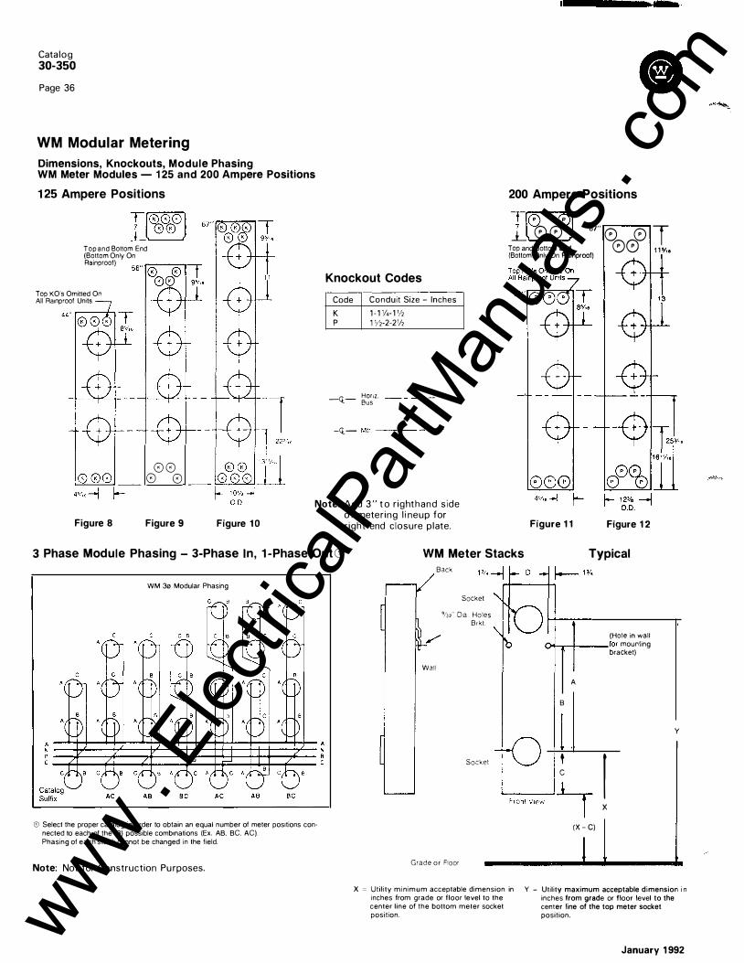
Catalog
30-350
Page 36
WM Modular Metering
Dimensions, Knockouts, Module Phasing WM Meter Modules - 1 25 and 200 Ampere Positions
1 25 Ampere Positions
Top and Bollom End (Bollom Only On Rainproof)
Top KO's Omilled On All Ra1nproof Units
0 0 0 0
Knockout Codes --
Code Conduit Size - Inches K p
-Q-
1 - 1 1/4-1112 1 112-2-21/2
Honz. Bus
-Q- Mtr. ----
200 Ampere Positions
T(0 0J � 0 0 G7" 0 0 T Top and Bollom End (Bottom Only On Rainproof) 00 1 1 '1··
Figure 8 Figure 9 Figure 1 0 Note: Add 3 " t o r ight h a n d side
of metering l i neup for r ight end closure plate. Figure 1 1 Figure 1 2
3 Phase Module Phasing - 3-Phase In, 1 -Phase Out ffi
WM 3o Modular Phasing
G) Select the proper catalog in order to obtain an equal number of meter positions connected to each of the (3) possible combinations (Ex. AB. BC. AC). Phasing of each stack cannot be changed in the field.
Note: Not for Construction Pu rposes.
WM Meter Stacks
Wall
Back
Top Meter Socket
9/n" 01a Holes in Mtg. Brkt.
Bottom Meter
Socket
Typical
(Hole in watt
1..1'1.,--t---for mounting bracket)
A
B
y
Stele V1ew ! I '-F-r-on_t_V_ie_w__, _1___,-l X (X - C)
Grade or Floor Level -------------------
X = Util ity minimum acceptable dimension in inches from grade or floor level to the center line of the bottom meter socket position.
Y � Utility maximum acceptable dimension i n inches from grade or floor level to the center line of the top meter socket position.
January 1 992
www . El
ectric
alPar
tMan
uals
. com

Three Phase Horizontal Buss
CAT. NO.
W3M420RAB HORIZONTAL BUS RATINGBOO AMPS 208YI1 20 V.A.C. 30-4W
(RAINPROOF) TYPE 3R ENCLOSURE
EACH METER SOCKET RATED 200 AMPS. CONTINUOUS
TYPICAL WIRING DIAGRAM
EQUIPMENT GROUNDING TERMINALS
CAT. NO.
W3M320R HORIZONTAL BUS RATINGBOO AMPS 208Y/1 20 V.A.C. 30-4W
c
(RAINPROOF) TYPE 3R ENCLOSURE
EACH METER SOCKET RATED 200 AMPS. CONTINUOUS
2
TYPICAL WIRING DIAGRAM
EQUIPMENT GROUNDING TERMI NALS
January 1992
CAT. NO.
W3M420RBC HORIZONTAL BUS RATINGBOO AMPS 208Y/120 V.A.C. 30-4W
Catalog 30-350
Page 37
Typical Meter Stack Schematics
(RAINPROOF) TYPE 3R ENCLOSURE
CAT. NO.
W3M420RAC HORIZONTAL BUS RATINGBOO AMPS 208YI1 20 V.A.C. 310-4W
(RAINPROOF) TYPE 3R ENCLOSURE
EACH METER SOCKET RATED 200 AMPS. CONTINUOUS EACH METER SOCKET RATED 200 AMPS. CONTINUOUS
TYPICAL WIRING DIAGRAM
EQUIPMENT GROUNDING TERMINALS
TYPICAL WIRING DIAGRAM
- --- ,
- A N
3
2
EQUIPMENT GROUNDING TERMINALS
@ Westinghouse CAT 110.
FORM NO 380·045·59 REV 1
W3M41 2RBC (RAINPROOF) HORIZONTAL BUS RATING 800 AMPS 208Y/120 V.A.C. �-4W TYPE 3R ENClOSURE
ALL iERMINALS SUITABLE FOR
AL-CU CONDUCTORS. CIRCUIT
BREAKERS SUITABLE FOR AL.CU
WHEN MARKED "AL.CU." EACH MElEI SOCIET UltD 125 AIIIIPS. ootmNUOUS. nPICAL WIIIIIIG OIAGIAII
315407-U ,,..,.., 3�311-U IF51HOR"TH.U.WIS Rf.OUIREO ORDEI'!MSTI� CAT NO
TERMINAL SYMBOLS WIRE RANGES
1210 TO 14 AWG CU
-0 1210 TO 12 AWG AL + f 1 /0 T 0 6 AWG AL.CU
� 16 AWG AL-CU
WM!>J �EUT!W_COtiNE OR CAl ltO � ISO!J<T[O
IF """"U"'-BVl'iOSS ISIIEOUIFIEO OAOfR W£S11NGHOVSE C.O.l NQ
o\IITOMATIC TJIP ISIIIDICATED iliWIDl.E POSITIOII.IDWAY 8£lWUII"OII"AIID"OW'TO I£STOitE SUIICf., IIO'IEIWI Dl.E TO ''Off'' TH£11 ''1111"
P ... Eli!OAAO TER .. iN�lS SUITABlE FO'l &0" OR 7�" CQNOI)C-1005 Gl�UifEIRU."ERfl'R ... IN.o.LS 5UPl.8U FOREITHERi50"C OO
0R 7�"<;: 0R 71'<;:C0N()�QR:S SE E C00CU" 6AEME� MAA"Iml
SIIIIT CIICUIT CUnt:IT UniMi, IO,OOI RIS S'fiMmiCil MII'EIU, 240 VOLTS UliMUM. SHOll" CIIQIIT Unll6 UMITtll TO UIJJ(Sl 111Tlllllmll6 tAI'ACm Of MY Dma: IIISTMWI. WHEII rao. TtCTtD IT AClASST fUSl l2011 MlrMAll ... SIIDIT QIQIIT Unll& IS IOCI.IIDD DSSYIIMmiCII. AllrEIES, 240 VOLTS IWIMUM. SEE To\ll.L MT CIICUIT lllAIUS MJOlD 01 IEI'IJCED SIWJ. IE Of Ttl( WH IIIIIUFACTUIU. mE, o\aD IITtiiiiPTlll& W'IICJTT.
IW:tMU• SitOIT MAIN DISCONNECT TENANT MAIN BREAKER CIIICUIT CUIIEIIT
WESTINGHOUSE TYPE UniMi · AllrEIU @ Ull/240 'fOt.TS M.U.
WSST FUSl II (IO,OIICI AICj 11,1100 iOO AIIIr . • .u. 1111 (50-IZSAI (U.OOO AICI IGO,eDO
QASS T FUSE (IO,OOO AIC) II,DDO 1200 Alllr. IW. [42,000 AIC) IGO,OOO
SHORT CIRCUIT CURRENT RATING IS 22 000 AMPS WHEN USED WITH UGPS PULLOOX WLHCP LUG KIT AND WESTINGHOUSE TYPE EJRH CIRCUIT BREAKERS
TIGHTEN ALL ELECTRICAL CONNECTIONS BEFORE ENERGIZING DO NOT WORK ON THIS E IPMENT WHILE ENERGIZED
www . El
ectric
alPar
tMan
uals
. com
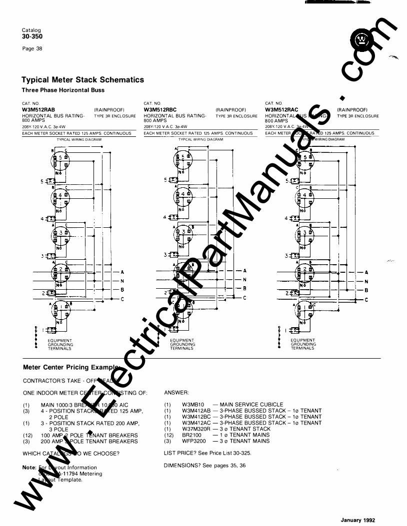
Catalog
30-350
Page 38
Typical Meter Stack Schematics Three Phase Horizontal Buss
CAT. NO. CAT. NO. CAT. NO.
Cl
W3M51 2RAB (RAINPROOF) W3M51 2RBC (RAINPROOF) W3M51 2RAC (RAINPROOF) HORIZONTAL BUS RATING- TYPE 3R ENCLOSURE HORIZONTAL BUS RATING- TYPE 3R ENCLOSURE HORIZONTAL BUS RATING- TYPE 3R ENCLOSURE BOO AMPS BOO AMPS BOO AMPS 208Y 1 20 V.A.C. 30-4W 208Y 1 20 V.A.C. 30-4W 208Y 1 20 V.A.C. 30-4W
EACH METER SOCKET RATED 1 25 AMPS. CONTINUOUS
TYPICAL WIRING DIAGRAM
EACH METER SOCKET RATED 125 AMPS. CONTINUOUS
TYPICAL WIRING DIAGRAM
EACH METER SOCKET RATED 1 25 AMPS. CONTINUOUS
TYPICAL WIRING DIAGRAM
2
EQUIPMENT GROUNDING TERMINALS
Meter Center Pricing Example:
CONTRACTOR'S TAKE - OFF READS:
c
ONE INDOOR METER CENTER CONSISTING OF:
( 1 ) MAIN 1 000/3 BREAKER 1 0,000 AIC (3) 4 - POSITION STACKS RATED 1 25 AMP,
2 POLE ( 1 ) 3 - POSITION STACK RATED 200 AMP,
3 POLE ( 1 2) 1 00 AMP 2 POLE TENANT BREAKERS (3) 200 AMP 3 POLE TENANT BREAKERS
WHICH CATALOGS DO WE CHOOSE?
Note: For Layout I nformation order SA-1 1 794 Metering Layout Template.
4 4
3 ,Ill 2
I I EQUIPMENT GROUNDING TERMI NALS
ANSWER :
c
I , ( 1 ) W3MB1 0 - MAIN SERVICE CUBICLE
EQUIPMENT GROUNDING TE RMI NALS
( 1 ) W3M41 2AB - 3-PHASE BUSSED STACK - 1 o TENANT (1 ) W3M41 2BC - 3-PHASE BUSSED STACK - 1 o TENANT (1 ) W3M41 2AC - 3-PHASE BUSSED STACK - 1 o TENANT (1 ) W37M320R - 3 o TENANT STACK ( 1 2) BR2 1 00 - 1 o TENANT MAINS (3) WFP3200 - 3 o TENANT MAINS
LIST PRICE? See Price List 30-325.
D I M E NSIONS? See pages 35, 36
_f - A - N - B
c
January 1 992
www . El
ectric
alPar
tMan
uals
. com

I
LINE I
- J I I I ' I
SIGNinES DUPLEX � f BREAKER -�
INSULATCO Q
Catalog
30-350
Page 39
1 P�ase Main Brea ker and M a i n Lug nly Schematics to 225 Am peres
GROUND B A R � lnl � PULL OU T F'OR
OFF � ROTATE 90" CLOCK'MSE
LINE
!Zl !Zl
I � _...., ..., ' , � 1 I
� � 't -@ h
J"'I 9iP�"" OM �
�--------ffi-0-UN-0--�H-[2-N--RE-D-UI-R-E D---------------�L-0A_D ____
2
_
A
_ o;,,,,.., �_O __
��
------_j---
2
-
B
____ ,ru!ii ___ �_, _________ L_OA_D ________ 2_c ____________ _j
1 2 J 4 [lZ! !Zl FOR STORAGE
2125 Diagram 1
LINE
48 Diagram 3
12-20 Diagram 8
16-30 Diagram 12
20-24 Diagram 1 5
January 1992
LINE I I
�1 ' [ 5 6 - 1 2
Diagram 4 58- 1 6
Diagram 5
12-24 Diagram 9
16-32 Diagram 13
J
LINE
8-1 6 Diagram 6
1 6-20 Diagram 1 0
l�_:-�-i : ' CJ t- -cJ 2 :� � t:=l t - - -c;J ' : ' - � · -- - -L:=J b
i ; ��Elli' __ �:J �0 ' ' c:.:=J - - ·· -c:J 1 2 I 3 c::J- _ --c=J I d
15 - - -c:J 1 6 , , c::J- 1 8 I g CJ--- - - 20
BUND OR GROUND WHEN REQUIRED 20-20
Diagram 1 4
10-20 Diagram 7
16-24 Diagram 1 1
- [f------. L -l_ J.--------.
Main Breaker or Main Lug Depending Upon Load Center Catalog N u m ber Prefix (BI or ( L )
___J\_ or c=J BR PREFIX BREAKER � or 1- - - 1 BD PREFIX BREAKER
-- FACTORY WIRING
� - - - - FIELD WIRING
www . El
ectric
alPar
tMan
uals
. com
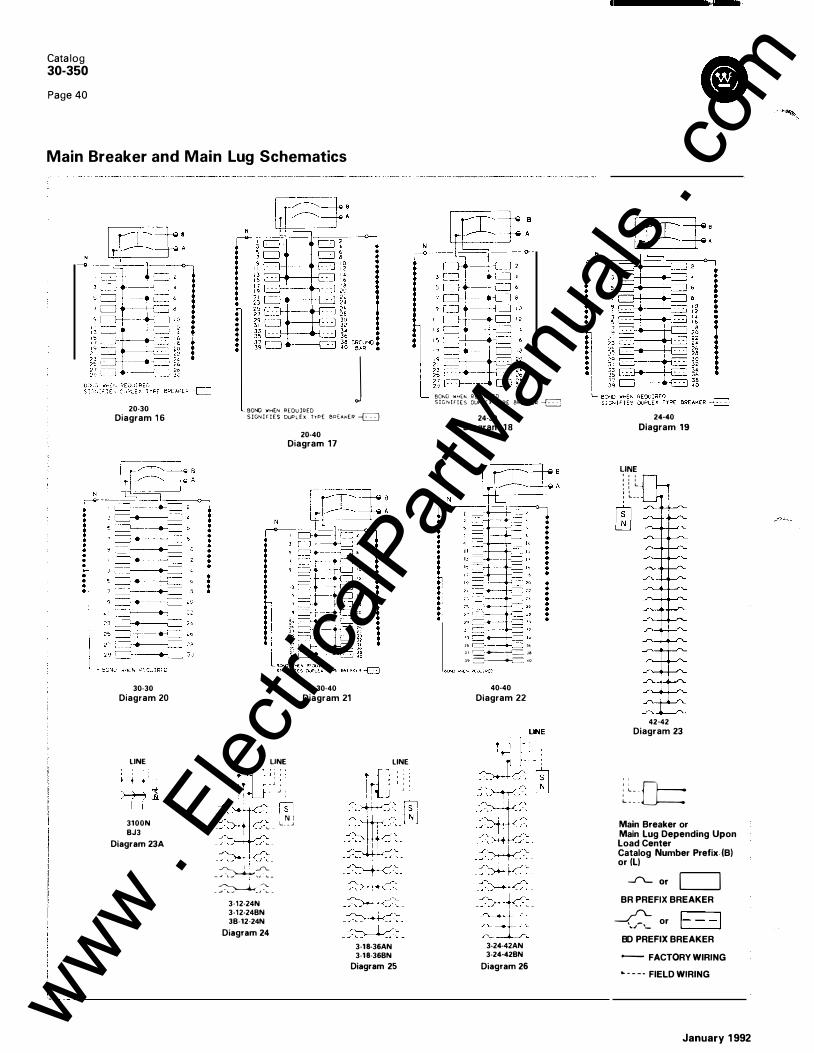
Cata log 30-350
Page 40
Main Breaker and Main Lug Schematics
20-30
Diagram 1 6
30-30
Diagram 20
LINE
3100N
BJ3
Diagram 23A
r i J
BONO \lr'H(N REQUIRED
S I GN l r l E S DUPLEX T'rPE 8R(,+.,KER � 20-40
Diagram 17
LINE r�;j : : I - .J I ' I ,
isl - , N I
- .._ - L _ _ J
- -
-��-
�_./L - J L ..-' 1 '' '- -
- � -
3·12-24N
3-12-24BN
JB-12·24N
Diagram 24
30-40
Diagram 21
LINE
3-18-36AN
3-18-36BN
Diagram 25
BOND WH(I\; REQuiRED SIGNIFIES OUPL()( TYPE 8R( A..K(R �
N
24-30
Diagram 1 8
JJ ;J� r===�t---+-<--, J<, J I � �� J� J� =·-------+-> � •o
40-40
Diagram 22
3-24-42AN
3·24-42BN
Diagram 26
24-40
Diagram 19
LINE : : : o 0 L ' ' ' ' ' L. _ _
42-42
Diagram 23
: : 0=: : L _ .
L • • -
Main Breaker or Main Lug Depending Upon Load Center Catalog Number Prefix (B) or (L)
__f\_ or C=:J BR PREFIX BREAKER
� or 1- - -1 "'" '-
BD PREFIX BREAKER
- FACTORY WIRING
L - - - · FIELD WIRING
January 1 992
www . El
ectric
alPar
tMan
uals
. com

3-30-42BN
Diagram 27
3-42-42CN
Diagram 30
LINE ' � � �
.
. .
. -.
�
LINE
I
- J 824-42DN
Diagram 36
January 1992
tt l -250 MCM CU. A L . I LINE I
BOND OR GROUND WHEN REQUIRED
3B-30-42AN 3B-30-42BN
Diagram 27A
LINE
Q cf :
� ' ' ' I - • "
.../"'-. I
[�] L _ _ _ _j
12-24DN
Diagram 31
LINE
Cs�' L - - - J
B30-42DN
Diagram 37
3-36-42BN
LINE Diagram 28
[EJ L _ _ _ _j
24-42DN
24-42EN
Diagram 32 LINE
I I I '
::-r�: _.r·_________._--� .F�-
� ----, SN �
L - - - _j 3B-30-42DN
Diagram 38
Catalog 30-350
Page 4 1
Main Breaker and Main Lug Schematics ·------- ----------·-·
LINE
3-42-42BN
Diagram 29
I��::-� I
.
.
.
.
.
- . - � " � .
� L _ _ _ _ ..J
3-18-36DN
Diagram 33
LINE
L_ _ _ _ _ _j 38-42-42DN
3B-42-42EN
Diagram 39
t n - 2 5 0 MCM CU . AL. LINE I LINE I
BOND OR GROUND WHEN REQUIRED
LINE
L _ _ _ 3-42-42DN
3-42-42EN
Diagram 34
LINE
I L _ _ _ _ _ J
B4242DN
B4242EN
Diagram 40
3B-42-42BN 3B-42-42CN
Diagram 29A LINE
� I L - - - .J
42-42BN
42-42EN
Diagram 35
Main Breaker or Main Lug Depending Upon Load Center Catalog Number Prefix (B) or (L)
--"'- or c=J BR PREFIX BREAKER
B D PREFIX BREAKER
-- FACTORY WIRING
• - - - - FIELD WIRING
www . El
ectric
alPar
tMan
uals
. com

Catalog
8 30-350
Page 42
Replacement Parts Load Centers
Catalog Interior Hardware Cover Neutral Deadfront Catalog Interior Hardware Cover Neutral Deadfront Number Assembly Kit Kit Assembly Shield-N3R Number Assembly Kit Kit Assembly Shield-N3R
Kit Kit Kit CD Kit Kit Kit CD B101 020CGT INTR44 HDWR1 FRONT1 NE UT3 L121 624CT I NTR8 HDWR1 FRO NT6 NEUT3 B101 220CGT INTR41 HDWR1 FRONT2 NEUT8 L121 624RT INTR9 HDWR1 NEUT3 SH LD2 B101220CT INTR41 HDWR1 FRONT2 NEUT8 L1 22024CT INTR1 1 HDWR 1 FRONT7 NEUT6 B101224RT INTR28 HDWR1 NEUT3 SH LD2 L1 22024RT INTR 1 2 HDWR1 NEUT3 SHLD3 B101620CT INTR31 HDWR1 FRONT3 NEUT3 L151224CT INTR 1 6 HDWR1 FRONT1 2 NEUT1 9
B101 624RT INTR32 HDWR1 NEUT1 0 SHLD4 L151 630CT INTR 1 4 HDWR1 FRO NTS NEUT1 6 B1 02020CT INTR43 HDWR1 FRONT4 NE UT8 L1 52030CT INTR 1 S HDWR 1 NEUT1 6 B102024RT INTR30 HDWR1 NE UT3 SH LD3 l201224CT INTR 1 6 HDWR1 FRONT1 2 NEUT1 9 B10816CT INTR39 HDWR1 FRONT1 NE UT9 l201224RT INTR 1 7 HDWR1 NEUT 1 9 SHLDS B121 624CT I NTR31 HDWR1 FRONT7 NE UT3 L202040CT INTR 1 8 HDWR1 FRO NT1 S NEUT1 7
B1 22024CT I NTR29 HDWR1 FRONT9 NEUT10 L202040RT INTR23 HDWR1 NEUT1 7 SHLD6 B122024RT INTR30 HDWR1 NEUT3 SH LD3 L202440CT INTR24 HDWR1 FRONT17 NEUT1 7 B151224CGT INTRS3 HDWR1 FRONT1 2 NEUT1 9 L203040CT INTR 1 9 HDWR1 FRONT1 0 NEUT1 7 B151 630CGT INTR 1 4 HDWR1 FRONT1 3 NEUT16 L203040RT INTR26 HDWR1 N E UT17 SHLD8 B151 630CT INTR 1 4 HDWR1 FRONT1 3 NEUT16 L204040CT INTR20 HDWR1 FRONT1 1 NEUT1 7
B1 52030CT INTR4S HDWR1 FRO NT20 NEUT16 L204040RT I NTR2S HDWR1 NEUT1 7 SHLD7 B1 52040RT INTRSS HDWR1 NEUT1 7 SHLD6 l2081 6RT INTR22 HDWR2 NEUT1 8 SH LDS B1 52430CT INTR46 HDWR1 FRONT1 6 NE UT1 6 N121224CT I NTR27 HDWR1 FRONT6 NEUT3 B1 53030CT INTR47 HDWR1 FRONT1 8 NEUT1 6 N121224RT INTR28 HDWR1 NEUT3 SHLD2 B1 53030RT INTRS7 HDWR1 NEUT17 SHLD8 N121624CT INTR31 HDWR1 FRONT7 NEUT3
B201 224CGT I NTRS3 HDWR 1 FRONT1 2 NEUT1 9 N121624RT INTR32 HDWR 1 NEUT1 0 SH LD4 B201 632CGT INTRS4 HDWR 1 FRONT1 4 NEUT1 6 N1 22020CT INTR43 HDWR1 FRONT4 NEUT8 B201 632CT INTRS4 HDWR 1 FRONT1 4 NEUT1 6 N1 22024CT I NTR29 HDWR1 FRONTS NEUT1 0 B202040CGT INTR48 HDWR 1 FRONT20 NEUT17 N1 22024RT INTR30 HDWR1 NEUT3 SHLD3 B202040CT I NTR48 HDWR 1 FRONT20 NEUT17 N201 224CT INTR3S HDWR 1 FRONT1 2 NEUT1 9
B202040RT INTR23 HDWR1 NEUT17 SH LD6 N201224RT I NTR33 HDWR1 NEUT1 9 SH LD5 B202440CT INTR56 HDWR1 FRONT1 7 NEUT17 N201632CT INTR34 HDWR1 FRONT1 4 NEUT1 6 B203040CT INTR49 HDWR1 FRONT1 8 NEUT17 N202040CT INTR36 HDWR1 FRO NT1 5 NEUT1 7 B203040RT INTR50 HDWR1 NEUT1 7 SHLD8 N202040RT INTR23 HDWR 1 NEUT1 7 SHLD6 B204040CT I NTRS1 HDWR1 FRONT1 9 NEUT17 N203040CT INTR37 HDWR1 FRONT1 8 NEUT1 7
B204040RT I NTR2S HDWR1 NEUT17 SH LD7 N203040RT INTR26 HDWR1 NEUT17 SHLD8 B4242CFN INTRS8 HDWR 1 NEUT20 SHLD9 N204040CT I NTR38 HDWR1 FRO NT1 9 NEUT1 7 B4242CRIN I NTRS8 HDWR1 N EUT2 1 SHLD10 N204040RT INTR2S HDWR 1 NEUT1 7 SHLD7 B4242CSN INTR58 HDWR1 N EUT20 SHLD9 N20816RT INTR22 HDWR2 NEUT1 8 SHLD5 B4242CYFN INTRS8 HDWR1 NEUT20 SH LD9 S61 2C I NTR 1 HDWR2 NEUT1
B4242CYSN I NTR58 HDWR1 NEUT20 SH LD9 S612CD I NTR1 HDWR2 NEUT1 B4242DFN I NTRV1 1 HDWRV1 C67 N F SH LDD9 S612CDG INTR1 HDWR2 NEUT1 B4242DRIN I NTRV1 1 HDWRV2 SH LDV6 S61 2CG INTR1 HDWR2 NEUT1 B4242DSN I NTRV1 1 HDWRV1 C66NS SHLDD9 S612R I NTR1 HDWR2 NEUT1 SHLD1 B4242DYFN I NTRV1 1 HDWRV1 C67NYF SH LDD9 S816C I NTR2 HDWR2 NEUT1
B4242DYSN I NTRV1 1 HDWRV1 C66NYS SH LDD9 S816CD INTR2 HDWR2 NEUT1 B4242EFN I NTRV 1 2 HDWRV3 C67 N F SHLDD 1 0 S816CDG INTR2 HDWR2 NEUT1 B4242ERIN INTRV1 2 HDWRV5 SHLDV7 S81 6CG INTR2 HDWR2 NEUT1 B4242ESN I NTRV 1 2 HDWRV3 C66NS SHLDD 1 0 S816R I NTR3 HDWR2 NEUT1 SHLD1 B4242EYFN INTRV1 2 HDWRV3 C67NYF SHLDD10 33042BFN INTRV22 HDWRV1 0 C32N F N E U 1 3
B4242EYSN INTRV 1 2 HDWRV3 C66NYS SHLDD10 33042BRIN INTRV22 HDWRV1 3 - NEU 1 3 SHLDV1 5 H151 632CT INTR34 HDWR 1 FRONT1 3 NEUT16 33042BSN INTRV22 HDWRV 1 0 C32 NS NEU 1 3 H 1 52030CT INTR4S HDWR1 FRONT20 NEUT1 6 33642BFN INTRV35 HDWRV1 0 C36NF NEU13 H1 53040CT INTR37 HDWR1 FRONT1 8 NEUT17 33642BSN INTRV35 HDWRV1 0 C36NS N E U 1 3 H202040CT I NTR48 HDWR1 FRONT1 S NEUT1 7 34242BFN INTRV2S HDWRV1 0 C38NF N E U 1 3
H203040CT I NTR37 HDWR1 FRONT1 8 NEUT17 34242BRIN I NTRV2S HDWRV1 3 - NEU 1 3 SHLDV1 7 H204040CT INTRS1 HDWR1 FRONT1 9 NEUT17 34242BSN INTRV25 HDWRV1 0 C38N S N E U 1 3 L121 224CGT INTRS HDWR1 FRONTS N EUT3 34242CFN INTRV4 HDWRV3 C45NF NEU1 SHLDD 1 6 L121 224CT INTRS HDWR1 FRONTS N EUT3 34242CRIN INTRV4 HDWRV5 NEU1 SHLDV8 L121 224RT I NTR6 HDWR 1 N EUT3 SH LD2 34242CSN INTRV4 HDWRV3 C44NS NEU1 SHLDD 1 6
CD Necessary for NEMA 3 R load centers. 4242CFN I NTR59 HDWR1 C45 N F NEUT22 SHLD9 ® Refer to Catalog 30-390 and PL 30-325. 4242CRIN I NTR59 HDWR1 NEUT22 SHLD 1 0 4242CSN INTRS9 HDWR1 C44NS NEUT22 SHLD9
January 1 992
www . El
ectric
alPar
tMan
uals
. com

NOTES
January 1992
Catalog 30-350
Page 43
www . El
ectric
alPar
tMan
uals
. com

Catalog 30-350
Page 44
Typical Load Center Assembly
B202040CT
Further Information Mod/Li ne Brochu re SA-1 1 648A Twi n Neutral Load Center Brochu re
SA-1 1 662A CPO Price List PL 30-325 Safety Switch Price List PL 30- 1 25 Renewal Parts Catalog 30-390 Res. Tim e Cu rrent Curves
Application Data 30-361 BPA Form 49808 Metering Template SA-1 1 764
Distributed By:
Westinghouse E lectric Corporation Distri bution and Control Business U n it Standard Distribution Products Division Pittsburgh, Pen nsylva nia , U.S.A. 1 5220
-
Front Assembly
BPA Procedures The branch price authorization (BPA) is an authorized deviation from publ ished/ discounts to meet specific com petitive situations at a g iven d istri butor location . The BPA form is used not only to satisfy the legal requ i rements affecting the sale of Westi nghouse CPO products to our custom er, but to provide an accurate, efficient means of m a nag ing our d istri butor price agreements. All authorized BPA discou nt m u lt ipl iers are loaded in Westing house AMS data base and automatica l ly price each cata log item at the t ime of order entry.
Primary B PA discount g roups ( L,C,G,S,E) apply to all cata log items with in their respective groups; however, sub-group discou nts ( LA,LB, etc) wi l l take precedence over the primary group, while a cata log exception wi l l override both pr imary a n d subg roups. I n other words, the computer system wi l l , upon order entry, search for the lowest authorized level for each cata log item , and price it according ly.
B202040CT Breakers Installed and Wired
Mounted Between Two Studs
Instructions Field Sales Request • Provide complete i nformation requ i red by
BPA form. ( Form 49808) • Request discount m u lt ipl iers requ i red to
meet com petit ion. • Obtain District Manager approval &
signature. • Fax or ma i l completed BPA form to the
Distri bution Support Center.
Support Center Authorization • Review, negotiate and authorize BPA
request. • Enter product code authorizations on AMS
data base. • Fax approved BPA to Field Sa les. • Maintain on fi le approved and signed
forms for i nternal audit.
Field Sales Confirmation • Add authorized BPA discount g roup m ulti
p l iers to the BPA discount tables provided on CPO price lists : 30- 1 2 5 and 30-325 a s req u i red.
• Tra nsmit the price l ists to the d istributor acknowledg ing and confi rming the a pproved levels that have been secured for h im.
Printed in U.S.A.
January 1 992 www . El
ectric
alPar
tMan
uals
. com

October, 1 986 Su persedes 30-350 Pages 1 -36 dated January 2, 1 986 For standard terms of sale, refer to Sel l i ng Pol icy 30-000 Mai led to : E, D, C/30-1 00A, 30-200A
Westinghouse Electric Corporation Bryant E lectric Division Bridgeport, Connecticut 06606
Circuit Protective Devices
Cata log
30-350
Page 1
www . El
ectric
alPar
tMan
uals
. com

Catalog 30-350
Page 2
Table of Contents, Specifications and Listings
Table of Contents
Specifications, Listings
CIRCUIT B R EAKERS
Page 2
Circuit Breaker Types . . . . . . . . . . . . . . . . . . . . . . . 3
Circuit Breaker Features, Dimensions . . . . . . . . 4 Circuit Breaker Handle Color Code . . . . . . . . . . . 5
Circuit Breakers 1 " per pole . . . . . . . . . . . . . . . . . . 5
Circuit Breakers W' per pole, Replacement Breakers, and Special Application Breakers . 6
Circuit Breaker Ratings and Terminal Data . . . . 7 Circuit Breaker Accessories and Wire Ranges . 8
LOAD CENTERS
Load Center Features and Catalog Number Interpretation . . . . . . . . . . . . . . . . . . . . . . . . . . . . 9
Main Breaker, Single Phase, Load Centers . . . . 1 0
Main Breaker, Three Phase, Load Centers . . . . . 1 1
Main Lug, Single Phase, Load Centers . . . . . . . . 1 2
Main Lug, Three Phase, Load Centers . . . . . . . . 1 3
Mobile Home Panels, Single Phase . . . . . . . . . . . 1 4 Load Center Dimensions and Knockout Data . . 1 5, 1 6
Riser and Feed-Thru Panels . . . . . . . . . . . . . . . . . 1 7 Load Center Accessories . . . . . . . . . . . . . . . . . . . . 1 8
SPECIFICATIONS, LISTI NGS
CLASS CTL National Electrical Code Paragraph 384- 15 requires branch circuit load centers to be provided with physical means to prevent the installation of more over-current devices than that number for which the enclosure was designed, rated, and approved. Class CTL Duplex and Quadplex breakers (identified by a catalog number prefix BD or BQ) are equipped with a UL listed rejection tab over the line terminal. All load center enclosures have appropriately notched stabs to accept these rejection tab Class CTL breakers. Duplex and Quadplex breakers manufactured without the rejection tab ( identified by a catalog number prefix BR or BRD) are available for replacement purposes in older enclosures.
FEDERAL SPECIFICATIONS All load center enclosures meet Federal Specifications W-P-1 1 5a, Type 1 , Class 2 requirements. All 1 pole and 2 pole 1 20/240 volt breakers, both 1" and W' per pole meet the requirements of Federal Specifications W-C-375a Class 1 a All 2 pole and 3 pole 240 volt breakers meet Federal Specification W-C-375a Class 1 b.
CANADIAN STANDARDS ASSOCIATION LISTING All 1 pole and 2 pole 1 20/240 volt breakers, both 1" and '12'' per pole, 225 ampere maximum, are listed as Certified by the Canadian Standards Association, Guide No. 69-1 1 . 19 , Class 1432, File 1 8328. All 1 -pole GFCB ' Ground Fault Circuit Breakers with suffix CS are listed as certified by the Canadian Standards Association, Guide No. 1 42-R-3, Class 1 45 1 , File 33607.
Page M ETER SOC KET PAN ELS
Meter Socket Panels . . . . . . . . . . . . . . . . . . . . . . . . 1 9 Meter Socket Panel Dimensions and Knockout
Data . . . . . . . . . . . . . . . . . . . . . . . . . . . . . . . . . . . . . 20, 21
METER CENTERS
Quick-Stack Meter Center Features . . . . . . . . . . . 22 Quick-Stack Meter Centers . . . . . . . . . . . . . . . . . . 23 Quick-Stack Commercial Meter Center
Features . . . . . . . . . . . . . . . . . . . . . . . . . . . . . . . . . 24 Quick-Stack Commercial Meter Centers . . . . . . 25 Quick-Stack Service Cubicles . . . . . . . . . . . . . . . . 26, 27 Quick-Pack Meter Centers . . . . . . . . . . . . . . . . . . . 28 Meter Center Accessories and System Short
Circuit Rating Table . . . . . . . . . . . . . . . . . . . . . . . 29 Quick-Stack Meter Center and Service Cubicle
Dimensions and Knockout Data . . . . . . . . . . . . 30, 31 Quick-Stack Commercial Meter Center
Schematics and Phase Balancing Data . . . . . 32 Quick-Stack Commercial Meter Center
Dimensions and Knockout Data . . . . . . . . . . . . 33 Quick-Pack Meter Center Dimensions and
Knockout Data . . . . . . . . . . . . . . . . . . . . . . . . . . . 34
SCHEMATICS, IN DEX
Schematics . . . . . . . . . . . . . . . . . . . . . . . . . . . . . . . . 35-38 Numerical Index . . . . . . . . . . . . . . . . . . . . . . . . . . . . 39 Regional Sales Offices . . . . . . . . . . . . . . . . . . . . . . Back cover
SERVICE ENTRANCE All split bus, main breaker, and unit enclosures, and all main lug enclosures thru 12 circuit single phase and 18 circuit three phase are listed as suitable for use as Service Equipment when installed in accordance with NEC-230. Meter socket units are listed as Service Equipment.
U N DERWRITERS' LABORATORIES IN :. LISTING
All load centers comply with the Underwriters· Laboratories Inc. standards and are listed as follows:
"Standard for Panelboards" UL67; Guide No. 320 SO File E31679. "Standards for Cabinets and Boxes" UL50; Guide No. 60 A 19 File E34724. "Requirements for Wire Connectors and Soldering Lugs", UL486; Guide No. 461 1 0-C File E7830. "Requirements for Service Equipment", UL869; Guide No. 380 FO File E1 1 737.
All MLK series lug kits comply with Underwriters' Laboratories Inc. standards and are listed under Guide No. DHJR, File E31424, Volume W, Section 1 7. All grounding bars manufactured comply with Underwriters' Laboratories, Inc. standards and are listed under Guide No. DHJR, File E31 424, Volume W, Section 1 7. All circuit breakers 1 5 amperes and larger comply with the Underwriters' Laboratories Inc. "Standard for Branch Circuit and Service Circuit-Breakers" UL489; Guide No. 60 1 0.2 File E31 424, and "Requirements for Wire Connectors and Soldering Lugs". UL486; Guide No. 461 1 0-C File E7830. All Bryant breakers and load centers where marked, are suitable for use with 60/75 "C rated wire. All devices comply with the 22,000 A. I . C. - 1 0,000 A. I. C. U.L. series connected components File DKSY2 of the Recognized Components Index.
October, 1986 www . El
ectric
alPar
tMan
uals
. com

Cl BR CIRCUIT B REAKERS
Bryant BR plug-on breakers in t h e standard 1 " p e r p o l e p a c k a g e have color-coded handles for easy ampacity identification and unique c o l o r - c o d e d cases that i n d i c a t e U L l i s t e d 1 OKA o r 22KA interrupting ratings.
All are Type I . C. (interchangeable) devices; several ratings are SWD and HACR approved. Typical ampacity range for B R breakers i s 1 5-1 25 amperes.
G FCB R B R EAKERS B r y a n t G F C B (ground fault circuit breaker) comb i n e s s t a t e - o f t h e - a r t h y b r i d e l ectro n i c technology with a circ u i t b r e a k e r ': ' . mechanism in a compact 1 " packag e. The G FC B a u t o m a t i c a l l y senses hot wire
to-ground faults in a 4 to 6 milliampere range, and shuts off the power thus providing an extra margin of safety beyond that of conventional circuit breakers. GFCB applications include bathrooms, cellar outlets, swimming pools, outdoor branch circuits, and kitchen branch circuits. Available in UL listed 1 20 and 1 20/240V ratings. Bryant also offers n o n - U L l isted ground fault breakers for international applications as well as ground fault devices for equipment protection.
EQUIPM E NT PROTECTION BREAKERS
l . .
This device is sim-ilar to the Bryant G F C B , e x c e p t that it is designed to protect equipment (not people) against damage f r o m a r c i n g ground faults. It is ava i l able with a 30MA tri p l eve l . Appl icat ions i n -c l u d e i n f r a r e d
heating equipment, computer equipment, process control equipment etc. Special markings and color-coding immediately differentiate it from a GFCB breaker.
October, 1986
BJ CIRCUIT B R EAKERS Avai lable in 1 25 thru 225 ampere frames, Bryant BJ plug-on breakers h ave 1 OKA and 22KA interrupting ratings and can be used as main or b r a n c h d i s c o n n e c t d e v i c e s . Color-coded handles identify amp a c i t y r at i n g s .
Large extruded aluminum box lugs, complies with UL 486B, provide cool operation. Tripping mechanism has thermal and magnetic protection for long-l ife performance. Rupture gas is safely vented into box gutter.
BD CIRCUIT B R EAKERS BD plug-on breakers have the same construct ion as Bryant BR 1" per pole devices except that 2 poles are in a spacesaving 1 " package. UL listed interrupting rating is 1 OKA. Color-co-ded handles identify ampacity rat
ing through 50 amperes. Some ratings are SWD and HACR approved . Exclusive CTL rejection feature allows only 42 circuits in the panel in compliance with NEG Article 384- 1 5.
BQ CIRCUIT B R EAKERS Quad plex ' construction of Bryant BQ plug-on breakers i n corporates two duplex breakers assembled together to provide various combinations of 2 pole and s i n g l e p o l e d e vices in a 2 " pack-a g e , a n d a l l o w compl iance with
NEG Article 240-20(b). The 2 pole combinations of Bryant BQ breakers are marked "independent trip" meaning that each pole of a 2 pole device trips independently of the other, but may be actuated jointly by means of the handle tie. Independent trip devices may only be used on 3 wire Edison circuits where the neutral is present.
Catalog 30-350
Page 3
Circuit Breaker Types Therm a l M a g n etic 40°C
BQC CIRC U IT BREAKERS Q u a d p l e x c o n struction of Bryant B Q C p l u g - o n breakers incorporates a special int e r n a l c o m m o n t r i p c a m . B Q C b r e a k e r s a r e avai lable in several combinations of 2 pole and sin-gle pole devices wherein the 2 pole
c i rcu its have an internal common trip mechanism. These breakers are labeled "common trip" and meet all the requirements of UL 489 paragraph 9.1 requiring multipole breakers to have common trip. Common trip breakers are required on all 240V circuits where there is no neutral present such as water heaters, baseboard heat, air conditioners and other motorloads.
SPECIAL APPLICATION BR EAKERS As the name im-
p l i e s , these dev i c e s a r e d e signed for special applications as required by the Nat ional E l ectri ca l Code.
Wat e r H e a t e r Breaker : Some watthou r meters i ncorpo rate rate register switches
used in conjunction with off-peak rates. Water Heater breakers do not derive their circuit from the loadcenter stab. The line & load side of the breaker are fed to terminals on the breaker. Except for these terminations, the device offers normal circuit breaker protection.
Switching Neutral Breaker: Primary application for the Bryant switching neutral breaker is for protection of process equipment such as gas pumps that utilize flammable liquids. Non-automatic pole breaks the neutral power leg, minimizing the danger of arc conditions.
2-Po l e B reakers 1 20V o r More to Ground: Used on Delta distribution systems, these Bryant breakers are applied on phase legs where voltage to ground is above 1 20V.
Non-Automatic Molded Case Switch : Identical to comparable circuit breaker frames with this exception: non-automatic molded case switches do not have thermal or magnetic trip elements. www .
Elec
tricalP
artM
anua
ls . c
om

Catalog 30-350
Page 4
Circuit Breaker Features and Dimensional Data Th ermal M a g n et ic 40°C
Heavy duty mechanism spring for reliable operation
Hardened cradle for positive action under fault conditions
Non-abrasive integrally molded pivot for quick mechanism response
One-piece moving contact arm for quick on/off response
Heavy duty line terminal and spring clip for quick load center installation and cool operation
Silver tungsten alloy contacts
Molded handle tie
Unique one-piece heavy-duty De-ion ' assembly for quick arc interruption
Color-coded handle for fast identification of ampere ratings
Calibrated one piece bimetal for reliable thermal trip function
1" Per Pole Module BR Series
1/2" Per Pole Module BD!BQ Series
One-piece frame assembly for dimensional stability and reliable operation
Four-rivet construction enhances strength and structural integrity of breaker case
Common trip cam assures simultaneous pole opening
Heavy duty multi-strand flexible copper shunt for cool operation
UL 4868 approved terminal assembly for use with copper or aluminum wire
Magnetic assembly for reliabl,e short circuit protection
Large gas port for venting short circuit gases safely into load center gutter
Full wiEith slot for channel type load center holdowns
1" Per Pole Module BJ Series
October, 1986 www . El
ectric
alPar
tMan
uals
. com

Catalog 30-350
Page 5
Plug-on Circuit Breakers 1" per p o l e - Types B R , G FCB, G FE P, BJ
Therm a l M a g n etic 40°C
BR120 BR230 BR340 GFCB120 BJ3200
TYPE B R B VAKERS, 1 " PEB P O L E 1 20 24f' OR ;;;fO VOL T-- -
�- � :o��;o VAC _ �-Requires 1 Space i __ gper_ Shelf Cilrton; �8 per 14 Lb: Package
2 Pole 1 20/240 VAC Common Trip
Requires 2 Spaces 6 per Sh�lf Carton; 24 per 1 6 Lb. Package
l 3 Pole � I 240 VAC Common Trill___ I Requires 3 Spaces 4 per Shelf Carton; 1 6_pe� 1Z.Lb Package _j
1 1 0,000 AIC ·. 22,000 AIC 1 0,000 AIC 22,000 AIC 42,000 AIC ® 1 0,000 A�C --��,_Q�O AIC ------� CAT. NO. CAT. NO. CAT. NO. CAT. NO. CAT. NO. CAT. NO. CAT. NO. I
1 0 1 5 20 25 30 40 50 60 70 80 90
BR1 1 0Ql BR1 1 5Q)Ql@ BR1 20G:IQJ@ BR125 BR130@ BR140 BR1 50 BR1 60 BR1 70
BRH1 1 5 BRH120 BRH125 BRH130 BRH140 BRH150 BRH1 60 BRH170
BR210® BR215® BR220® BR225® BR230® BR240® BR250® BR260® BR270® BR280® BR290®
l
BRH215 BR315 BRH315 BRH220 BR320 BRH320 BRH225 BRH230 BR330 BRH330 BRH240 BR340 BRH340 BRH250 BR350 BRH350 BRH260 BR360 BRH360 BRH270 BR370 BRH370
BRH290 BR390 BRH390 100 1 1 0 1 25
BR2100® BRH2100 BRHH2100 BR3100 BRH3100 BR21 1 0® BRH2110 BR21 25® BRH2125 BRHH2125
TYPE GFCB <i ; W U N D FAU LT C I R C U IT B R t:A K t: H �3 1" P E R P O L E 1 :uVAC or 120 '240VAC, 10,000 & 22 .000 AlC 1 Po l e for Single Circuit Application, 2 Pole for Multi-Wire and Appliance Circuits. i I 1 Pole
1 20 VAC [ __ - ·----2 Pole � 120/240 VAC Common Trip � �
AMPS ; Requires 1 Space L 1 per Shelf Carton 1 P5MA for single circuit
Requires 2 Spaces 1 per Shelf Carton
2P5MA for multiwire and appliance circuits 20 per 1 0 Lb. Package applic.<llio_n _ __ _ 5 per 6 Lb. Package _
i -10,000 AIC - --,
1--- --- - - -------CAT. NO.
GFCB1 1 5 GFCB120 GFCB125 GFCB130 __ __
_____ _j
22,0_00 AIC CAT. NO.
GFCBH 1 1 5 GFCBH120 GFCBH125 GFCBH130
TYPE BJ B R i :.i \KERS, 1 20/240 OR 240 VU�. 1 0,000, 22,0C J . AND 42 ,000 AIC
i 2 Pole :=k f- 1 20/24_0 VA_C ComlllO_n_Trip I Requires 4 Spaces , 1 per Shelf Carton, 1 0 per 20 Lb. Package '
1 o,oqo AIC--_� -�2,ooo �c; .--T <12,ooo AIC® __ ______ _ + _____ CAT. NO. l _ C_�T· t-1� .. _1 CAT. NO.
BJ2125 I BJH2125 BJ2150 BJH2150 BJHH2150 BJ2175 BJH2175 BJ2200 BJH2200 BJHH2200 BJ2225 BJH2225 -- _ _l_ _
_ - · - · -- -- ---- - --
1 0,000 AIC CAT. NO.
GFCB215 GFCB220 GFCB225 GFCB230
tH.
22,000 AIC CAT. NO.
GFCBH215 GFCBH220 GFCBH225 GFCBH230
3 Pole -----1'-----240 VAC Common Trip � Requires 6 Spaces 1 per Shelf Carton, 5 per 1 8 Lb. Package ,
1 0,000 AIC 22,000 AIC CAT. NO. CAT. NO.
BJ3125 BJ3150 BJ3175 BJ3200 BJ3225
BJH3125 BJH3150 BJH31 75 BJH3200 BJH3225
CD Switching duty rating. 0 One pole, 1" per pole breakers are available with high magnetic
settmg for switching large tungsten lamp loads. Add suffix H to catalog number.
0 BR t -pole breakers also carry listing for HACR type. Add HACR suffix to catalog number when ordering.
@ BR 2-pole breakers are "UL Ltsted HACR Type" thru 60 amp, and are suitable for use as branch circuit protective devices in multi-motor and combination load installations commonly involved in heating, a1r conditioning, and refrigeration equipment.
October, 1986
i· y p [ G F E P G R O U N D FAU LT F: O IJ I P M E N T PROTECTORS, 1" P E R POLE
or 120 240VAC, 10,000 AIC
AMPS
1 5 20 25 30
�fo0�AC
-�-�fo%e40 �A;-� Requires 1 Space I Requires 2 Spaces 1 per Shelf Carton 1 per Shelf Carton 20 per 9 Lb. Package! 5 per 5 Lb. Package I 1 P30MA for 1 2P30MA for I single circuit i multi-wire and application appJi<if1C_e circu its___ i
CAT. NO. CAT. NO. 1 GFEP1 1 5 GFEP120 GFEP125 GFEP130
- - - ---- ·-1 GFEP215 GFEP220 I GFEP225
_ _ _ _ II GFEP230 _
u , _ !, i ! l 13 HEt\I�EH HANDLE C O L O R C O D E
AMPS COLOR AMPS COLOR
1 0 PINK 70 YELLOW 1 5 MED. BLUE 90 DARK RED 20 MED. RED 1 00 BLACK 25 IVORY 125 DARK GREEN 30 MED. GREEN 1 50 BROWN 40 GRAY 1 75 AMBER 50 LT BLUE 200 i DARK BROWN 60 ORANGE 225 DARK BLUE
---- ----- -'- _ _l__ ____ CIRCUIT BREAKER CASE INTERRUPTING CAPACITY
1 0,000 A. I. C. BLACK - - - - -�,
22,0��:_C GRA'l'__
j ® Two pole 70 amp and larger breakers are available with MAIN
stamped on handle or case. Add suffix "B" to catalog number. ® 42,000 AIC BRHH & BJHH breakers are special application
breakers for use with QP meter centers only to maintain 42,000 AIC ratings. www .
Elec
tricalP
artM
anua
ls . c
om

Catalog
30-350
Page 6
Plug-on Circuit Breakers 1 12" per pole - Type CTL The rm a l M a g netic 40°C
8D1 5·20 80230-240 80230-2120 8RWH215
1 20/240 VAC Duplex Type 8D Two of 1 Pole Takes 1 Space
1 20/240 VAC Ouadplex Type 80 Independent Trip 1 20/240 V and 240 VAC Type 80C Common Trip Two of 2-Pole 240 V or One 2-Pole 240 V and �
1 2 per Shelf Carton 48 per 1 7 Lb. Package AMPS CAT. NO. 1 0- 10 1 5-1 5 1 5-1 5 1 5-20 1 5·20 1 5-30 20· 15 20- 15 20·20 20-20 20-30 25·25 30· 15 30·15 30·20 30-20 30-30 30·30 30-50 50-30
8D10-10CD 8D15-15C?l 8D15-15 HACR 8D1 5-20C?l 8D1 5-20 HACR 8D1 5-30 8D20-15C?l 8D20-15 HACR 8D20-20C?l 8D20-20 HACR 8D20-30 8D25-25 8D30-15 8D30-15 HACR 8D30-20 8D30-20 HACR 8D30-30 8D30-30 HACR 8030-50 8D50-30
Two of 2-Pole or One 2-Pole and Two 1 -Pole Takes 2 Spaces
6 per Shelf Carton 24 per 1 8 Lb. Package
AMPS
2p1 5-2p 15 2p20·2p20 2p20-2p30 2p20-2p40 2p20-2p50 2p25-2p25 2p30-2 of 1 p1 5 2p30-2 of 1 p20 2p30-2p30 2p30·2p40 2p30-2p50 2p40-2 of 1 p 15 2p40-2 o f 1 p20 2p40-2p40 2p40-2p50 2p50·2 of 1 p 15 2p50-2 of 1 p20 2p50·2p50
CAT. NO.
80215-215 80220-220 80220-230 80220-240 80220-250 80225-225 80230-21 1 5 80230-2120 80230-230 80230-240 80230-250 80240-21 1 5 80240-2120 80240-240 80240-250 80250-21 1 5 80250-21 20 80250·250
Two 1 -Pole 1 20/240 V Takes 2 Spaces 2-Pole Devices are Common Trip 6 per Shelf Carton 24 per 1 8 Lb. Package
AMPS
2p25-2 of 1 p 15 Com. Trip 2p30-2 of 1 p15 Com. Trip 2p30-2 of 1 p20 Com. Trip 2p40-2 of 1 p 15 Com. Trip 2p40-2 of 1 p20 Com. Trip 2p50·2 of 1 p1 5 Com. Trip 2p50·2 of 1 p20 Com. Trip 2p1 5-2p 15 Com. Trip 2p20-2p20 Com. Trip 2p20-2p30 Com. Trip 2p20-2p40 Com. Trip 2p20-2p50 Com. Trip 2p25-2p25 Com. Trip 2p30-2p30 Com. Trip 2p30-2p40 Com. Trip 2p30-2p50 Com. Trip 2p40-2p40 Com. Trip 2p40-2p50 Com. Trip 2p50-2p50 Com. Trip
CAT. NO.
80C225·21 1 5 80C230·2 1 1 5 80C23D-2120 80C24D-21 1 5 80C24D-2120 80C25D-2 1 1 5 80C250·21 20 80C215·215 80C220·220 80C220·230 80C22D-240 80C220·250 80C225·225 80C230·230 80C230·240 80C230·250 80C240·240 80C24Q-250 80C25D-250
For replacement in enclosures manufactured prior to 1 968 with unnotched stabs.
1 20/240 VAC Duplex@ 1 20/240 VAC Ouadplex Type 8RD® 12 per Shelf Carton, 48 per 17 Lb. Carton 6 per Shelf Carton, 24 per 1 8 Lb. Carton
1 20/240 VAC Ouadplex Type 8RDC® 6 per Shelf Carton, 24 per 18 Lb. Carton
AMPS CAT. NO. AMPS CAT. NO. AMPS -,------�C7A=��N�O�.
------I
1 5· 15 1 5·20 20· 15 20-20 30·30
8R1 5-1 5 8R1 5-20 8R20-15 8R20-20 8R30-30
' .. l i\ 1.. i\ ! > P l i ! ! l ! · c !, l
2p1 5-2p 15 2p20-2p20 2p30-2p30 2p30-2p40 2p30·2p50
Water Heater Breakers Switching Neutral Breakers
2 Pole, 1 20/240 VAC 10,000 AIC 6 per Shelf Carton 24 per 1 5 Lb. Package
� LINE � LOAD
With Isolated Line Terminals for Separately Mounted Water Heaters
Requires 2 Spaces AMPS
1 5 20 30
CAT. NO.
8RWH215 8RWH220 8RWH230
·;:D All breakers 15 amp and above UL L1sted. �?) Switchmg duty rated. ::1: Two of 1 Pole takes 1 Space
2 Pole, 1 20 VAC 1 0,000 AIC � OUT
� .. NEUTRAL 6 per Shelf Carton 24 per 1 5 Lb. Package
AMPS
1 5 20 30
With Switching Neutral Pole for Gas Stations
Requires 2 Spaces CAT. NO.
8RSN215 8RSN220 8RSN230
(4) Two of 2-pole 240V takes 2 spaces
8R415 8R420 8R430 8RD230-240 8RD230-250
2p1 5-2p1 5 Com. Trip 8RDC21 5·21 5 2p30-2p30 Com. Trip 8RDC230-230 2p30·2p40 Com. Trip 8RDC230-240 2p30·2p50 Com. Trip 8RDC230·250
Delta 240V Breakers
2 Pole, 240 VAC 10,000 AIC
Non-Automatic Molded Case Switches
2 Pole, 2 3 Pole, 2
40 VAC 40 VAC :=1=: 6 per Shelf Carton
24 per 1 6 Lb. Package
AMPS
1 5 20 30 40 50 60 70
Where Voltage Exceeds 120 Volts
to Ground Requires 2 Spaces
CAT. NO.
8R215H 8R220H 8R230H 8R240H 8R250H 8R260H 8R270H
AMPS
50 60
1 00 225 1 00 225
For lJse as Disconnect Contains No Magnetic
Trip Properties
POLES CAT. NO.
2 8R250NA 2 8R260NA 2 8R2100NA 2 8J2225NA 3 8R3100NA 3 8J3225NA
October, 1986 www . El
ectric
alPar
tMan
uals
. com

Catalog
30-350
Page 7
Circuit Breaker Ratings and Term inal Data
TYPE ---� -
AMP RATING UL LISTED INTERRUPTING
FED SPEC CAPACITY RMS SYM AMPS
I I �------ - ___ L -I BD I 1 5-50 �--:}�-= -=�1 - 1��52
05 �-------------�---!.� I BRH I r1�H-H��-��r 1 5- 125
1 5- 125 1 25-225
f�-=---:r- · :�::: ��� · 1 ::: L - -- --- -�r l- ��� ----j-
W-C-375b
1 0a, 1 1 a, 1 2a 1 0a, 1 1 a, 1 2a
1 2a, 1 2b 1 4a, 14b 14a, 1 4b 14a, 1 4b 21a
1 20/240 VAC
1 0000 1 0000 1 0000 22000 42000 1 0000 22000 42000
240 VAC
1 0000 22000 42000 22000 65000 42000 42000 42000 L�� � �-=t :��: � :�� 1 25000
I GFCB i 1 5-30 ! - -
-- ---�+ -
1 5-30 L _ _{'FCBf:i __ _j_ _ 1 0000 22000
CD BRHH & BJHH breakers are special application breakers for OP meter centers CVSee Alternate Terminals table at right Current Carrying \�.11pacities of Conductors Not more than three conductors in raceway or cable or earth (directly buried), based on ambient temperature of 30°C (86°F)
Ampacities of lns;J IMed Conductors
Size __ le-�� Tempenlt�re RaiingotConductor, See Table 31 o-13 60"C 75�C --85'c'-96�c�l -6iJ�c i ?EtC- - 85°C 90"C
(140"F) ( 16�"F) ;_��"����O"f')j (1 67'F); (1 85"F) (194"F) TYPES TYPES
' TYPES I TYPES I TYPES : TYPES TYPES I TYPES
�,
Size
BRKR
DA DK LA600 MA NB
TERM TYPE
PRESSURE
TA400DA1CV TA400KCV TA600LACV TAROOMA2CV TA1 200NB1 CV CONNECTOR
PRESSURE
TERMINAL
1 TA350DA TA350K TA600LA TA700MA1 TA1 201 NB1
TERMINAL DATA WIRE TYPE
60175°C NO. AWG RANGE
( 1 5-50A) #4-#14 BD, BQ (1 5-30A) #8-#14 BR
CU/AL (40-50A) #4-#1 0 BR (50-1 25A) #1 /0-#8 BR #2-300 MCM (1 25&225A) BJ
CU!AL 2 #3/0-250 MCM CU/AL 2 #3/0-250 MCM CU/AL 2 250-500 MCM CU/AL 3 #3/0-400 MCM CU/AL 4 #4/0-500 MCM CU/AL 4 #1/0-750 MCM
CU/AL 1 5-20A #8- 14 30A #4-14
ALTERNATE TERMINALS WIRE TYPE , NO. AWG RANGE
CU/AL 250-500 MCM CU/AL CU/AL CU/AL CU/AL
2 2 3
250-500 MCM 250-500 MCM #1 -500 MCM 500-750 MCM
IRUW, I IFEPW, v. Ml 1 TA, TBS, 1 IRUW, ! IRH, · v, Ml 'sr� .. I�ss .. •
AWG IT ITW IRH, jSA, AVB,: IT, ITW, I IRHW, AWG Consult factory for details on above alternate terminals.
tUF ' ' IRHW, ' SIS, I IUF I IRUH, SIS I
I IRUH, : I IFEP, ' : ITHW, IRHH , MCM ITHW, 1 I IFEPB, : ITHWN, , ITHHN,
I :����: 1 ���tt,HN. ����r· , IXHHw·
I j_IUSE I IXHHW' I IN/ , � - - - - - - - _l_ - r-
l 1 Copper Aluminum or Copper·clad Aluminum r - - 18 ___._
_------.------ -
- -- � - 1 4--t- --�� 201 1 201 1� I 1�� ' 12 251 251 30 I 301 I 201 201 25 � 10 30 351 40 401 25 30t 1 30 !_ 8 40 50 55 ' 55 ' 30 40 40 --r+
-�Ir: J! ·
-Jr! - 1 �r-:- i� �� �� �- -! ��}� _ (�- ��� �:! . �!� 1�! ' ��� ��� I 00 i 145 I 1 75 190 ' 195 1 1 5 1 35 145 ' 000 : 165 ' 200 215 ! 225 ' 1 30 1 55 i 1 70 : _o_ooo 1. _195 I _23_0 250 : 260 : 1 50 : 1 80 195 lr 230500 �.: 224150 II 2285§ -m I ��ft 1 �r : ��g 220
35a , 26a 31o 34a 1 35a I 210 · 25a ��g I 400 ' 280 I 335 365 i 380 I 225 ! 270 295 '---,
-��65ooo��l,
�-33_52
50--+
1' __
4328 _oo ' -��!)_-f -�o L?� j __ � 1 a_ J � 3
337_5o
� : 460 1 475 ' 285 I 340 j i 700 1 385 1. 460 500 ! 520 3 10 ' 375 1 405
j ��g i 1�g 1�� ;�; ;�� i ��g i ��; I 1�g I i 565 , 585 ! 355 , 425 • 465 lf ��fg-r !ii i�� -��rf- ��ft �6� t 1�r-c �g� 1 5ao 1 52a I 625 68a : 705 . 435 ! 52o 565 1 75a 1 545 . 65a , 7a5 1 735 i 455 1 545 595 _2ooo _ ��66� ! ___2��_j_��o_L 56a 61a Ampacity Correction Factors
251 35t 45 60 75 85 1 00 1 1 5
1 35 1 50 1 75 205 230 255 280 305 350 385 420 435 450 480 500 545 585 615 630
MCM
1 2 10 8 6 4 3 2 1 0 00 000 0000
250 300 350 400 500 600 700 750 800 900
1 000 1 250 1 500 1 750 2000
Ambierl!T For ambient temperatures other then 30"c;-ffiultjpiy the ampacities shown ' Ambient Temp� "C�o�':..?Y t�e al'prop���e_!��t?r�ho\\'� below� _ _ ��- � · Temp. oF
31 -40 ' .82 T .88 .90 ' .91 ' .82 I .88 �90 ' .91 87-104 41 �45 ; �71 i .82 �85 ' �87 I .71 : .82 .85 .87 1 05-1 1 3 46-5a : d58 .75 .8o 1 .82 lj .58 1 .75 �8o .82 1 1 4� 122 I 51 -60 I . ' . . �58 .67 I .71 � � I .58 .67 .71 1 23�141 I 61-70 1 . . . . .35 .52 1 .58 . . . . j .35 ' �52 �58 ' 142-158 �L . . � . : �_ ·- -�()__j_�_1 _ _l__��-_l _:_:�--'--�3()_ __ � .41 1 59-176
tThe overcurrent protection for conductor types marked with an obelisk (t) shall not exceed 1 5 amperes for 1 4 AWG, 20 amperes for 1 2AWG, and 30 amperes, for 1 0 AWG copper; or 1 5 amperes for 1 2 AWG and 25 amperes for 1 0 AWG aluminum and copper-clad aluminum after any correction factors for ambient temperature and number of conductors have been applied.
*For dry locations only. See 75°C column for wet locations.
M.lAinltJI'l Nurn!J(: �i Ua�"·d un ·l ab it.� i Conduit Trade Size (Inches) Type Letters Size ' AWG,
MCM TW, T, RUH, 1 4 RUW, 1 2 XHHW 10 (14 thru 8) 8
RHW and RHH 1 4 (without outer 1 2 covering), 1 0 THW 8
TW, 6 T, 4 THW, 3 RUH (6 thru 2), 2 RUW (6 thru 2), 1
. FEPB (6 thru 2), 0 ' RHW and 00 RHH (with- 000 out outer 0000 covering)
250 300 350 400 500
600 700 750
1/2 3/4
9 1 5 7 1 2 5 9 2 4
6 1 0 4 8 4 6 1 3
2 1 1 1 1
In l
1
25 1 9 1 5 7
1 6 1 3 1 1 5
4 3 2 2 1
of Conduit or Tubing
1 1/4, 1 1/2 2 21/2 3 : 31/2� c- - i
4 5 6
44 35 ' 26 : 1 2
29 24 1 9 1 0
7 5 4 4 3 2 1 1 1
! : 60 99 : 1 42[ : ' 47 i 78 i 1 1 1 [ 17 1 ! 36 60 85' 13 1 : 1 761 1 7 28 40. 62 84 1 1 08.
40 65 32 53 26 43 1 3 22
1 0 , 1 6 7 1 2 ' 6 ' 1 0 ; 5 9 4 6 3 5 3 5 2 . 4 1 3 ' 1 2 1 2 1 1 1 1 1 1
93 143 1 92 76• 1 1 7. 1 57 61 95 1 27 1 63 32 49 : 66 85 1 33 i -:- ' i 23 .. 36. 48 621 97;
.
141 il 1 71, 27 36' 4?. 73': 106 15 1 23: 31 40! 63: 91 1 3 ' 20• 27 341 54 ' 78 9 ' 1��
19 ! 25 ! 39 ' 571 8: 12 , 1 6. 21 33 49 7 i 10 ! 14 18 i 29 41 6 9 ; 12i 15 24i 35 5 7 . 1 0: 13:_ 20f 29
4 6 3 5 ! 3 ' 4 i 2 4 ' 1 1 3 :
'�
1 : 3 ! 1 1 2 : 1 , 2
8 10 : 7 9 6 i 8' 5 ! I 7 : 4 6 : ' ' 4 ! 5 3·, 4' 3· 4 '
16 : 23 14 ; 20 12 ! 18 ! 14 1 1 61 9 ' 14 i I i i 7 ! 1 1 ! 7 : 10 ' 6 9' www .
Elec
tricalP
artM
anua
ls . c
om

Catalog 30-350
Page 8
Circuit Breaker Accessories and Wire Ranges
BRQLW HLW BHLW
LOC K DOGS AND PADLOCK DEVICES
8
BASIC I NSTALLATION I N STAl GTIONS:
Three newly designed accessories provide positive, tamper-proof performance for circuit breakers installed in commercial, hightraffic and generally accessible areas. The BHLW and HLW lockdogs, the BRLW and BRQLW padlock devices are designed to hold the circuit breaker operating handle in the "ON" or "OFF" position. Protects critical operating circuits from unauthorized tampering or use. The load center cover holds these devices securely in place. Lockdogs and padlock devices do not defeat the trip function of the circuit breaker. (Padlock not supplied). Lockdog device can be reversed for "ON" or "OFF" handle position.
1 . Install and wire circuit breakers in accordance with N . E.C. and local codes.
I � I QHL
L
WIRE RANG E S :
� ITEM
HANDLE TIE
LOCKDOG
2. Install HLW, BHLW, BHGW, BRLW, or BRQLW according to instructions with each item. HLW has break-off tabs that proVIde Independent operation of inner or outer handles.
3. Punch-out appropriate "shingles" for circuit breaker handles in load center cover.
4. Secure cover to load center with cover screws. Items are now in place and cannot be removed.
5. For padlock devices, turn circuit breaker handle to the "on" or "off" position and install padlock. -r - ---- - -- -
CAT. NO. DESCRIPTION - -------r- ----
1 for adjacent poles of two Duplex breakers. SIMUL-TIE · : for outside poles of two Duplex breakers. rr two of BR ( 1 " per pole) breakers.
. -- ;�BD Duplex, and BQ Quadplex· water heater, and switch neutral breakers. Snap-on.
THS-1 THO-W BHT
ing HLW
I for BR ( 1 " per pole) BD Duplex and QP style breakers. . for BRH 3p
BHLW QHL
i for single pole GFCB and GFEP breakers. BHGW
CAR-TON
5 1 5
1 0 1 1 1
ST D . G. PK
5 3 5
1 0
0 0 0
0 25 1 0 25
') � ' - _
:'COCK Dmo�- for BD Duplex breakers (padlock not for BQ Quadplex · breakers included) for 1" BR ( 1 " per pole, BD Duplex and QP style breakers) .
Accessory for use with two adjacent BD Duplex Breakers w allows only one pair of poles to be in the "ON" position at a
hich
BRDL 1 1 0 BRQLW 1 1 0 BRLW 1 1 0
BD1 L MECHANICAL
INTERLOCK ny given time.
BD1 L 1 1 0
Circuit breaker load terminals are of the box lug type with screws backed off for ready insertion of wires. These terminals are listed with Underwriters' Laboratories Inc. for the following wire ranges:
1 -----r---------1- ____ BREAKER AMPERE RATI��-
--�
-CATALOG PREFIX -----��
! 10 , 1 5, and 20 BD & BQ (Duplex & Quadplex) BR ( 1 " per pole)
30, 40, and 50 BD & BQ (Duplex & Quadplex) BR (1 " per pole) 1
60 and 70 BR QP
90 and 1 00 BR
I QP 125 BR
1 50, 200, and 225 _j_
BJ ------�------
AWG WIRE RANGES
1 0- 14 Cu, 1 0-1 2 AI 10- 14 Cu, 8- 1 2 AI 6- 1 0 Cu, 4-8 AI 4- 1 4 Cu, 4-8 AI 2-8 Cu, 2-6 AI 2-1 4 Cu/AI 6- 1 /0 Cu, 4-1 /0 AI 1 -6 Cu/AI 6-1 /0 Cu Suitable for 1 /0 AI on 1 phase 3 wire service 2-300 MCM Cu'AI
October, 1986 www . El
ectric
alPar
tMan
uals
. com

Catalog
30-350
Page S
Load Center Features and Catalog Number Interpretation Data
Keyslot mounting holes symmetrically located for ease of installation
Keyslot mounting hardware facilitates easy removal of interior for empty-box wire pulling
Standard 143/e" wide enclosures fit snugly between wall studs. Standard depth 37/e" /
Quick-fastener screws for installation of cover
Convertible interior for convenient interchangeability of plug-on main breakers or plug-on main lug kits 1 25A through 225A
I Interior is reversible for convenient bottom wiring
Hold-down screws safely secure main breaker (or main lug kit) to steel backpan in compliance with NEC requirements
Predrilled mounting holes for ease of installing ground bar kits
Predrilled mounting holes for ease of mounting neutral bar assembly on opposite side
Increased wiring gutter space for ease of wiring in compliance with NEC requirements
Box and shipping carton are code-dated to provide effective quality assurance
White silk-screened circuit directories adjacent to each circuit position for easy circuit identification
flush covers without embossing provide a clean, uncluttered wall finish
Bonding screw provision aligns mounting hole in neutral with predrilled hole in box for secure bonding
Compact "tuning fork" design of neutral assembly locates neutral terminals safely away from breaker terminals
Convenient flush adjusting screws, allow quick adjustment of interior for clean, neat appearance
Maximum variety of concentric knockouts, at top, bottom, end, rear and side One piece, tin plated Alstan®
process aluminum bus provides cool, reliable operation
LOAD CENTER CATALOG INTERPRETATION DATA 1 1ST _ 2ND 3RD 4TH---_r--5��-i�--6�H=- -=r-��-�+- ---=�=-= E�AMPI_E-- -------- -------1 f: : PHASE MAINS 1!':-'�A�gH MAX. NO. I MAX. I ENCLOSURE I SPECIAL '
IDENTIFIES ID
-
ENTIFIES MAIN CIRCUITS:Rs 1 A.J;?LLAe:LE , ��':��J 1
_
MT�-��L 1 F
-EATURE 1 3
�::::s:NL
Y BB
RE:---:-:-:s-re-:-�-�-r-Y+-
T_Y_P_E2_:-�-r:-u�--t�-;-p;;;;;-t
1
' -=--- ;_.:: t-N-em;l -- ---+G G�oun� I 1 - Single phase 1 0000 AIC 6 Circuits ' 12 Poles 50A ' I Bus •
I BH Main Breaker 8 Circuits 16 Poles - 1 00A I FN Flush i i3 phase 22000 AIC 1 0 CircUits 20 Poles . K 1 25A i SN Surface j !
I - Main Lugs 1 2 Circuits 24 Poles A 1 50A 1 6 Circuits 30 Poles B 200A Nema 3R 20 Circuits 32 Poles C 225A II 11 24 Circuits 40 Poles DD 300A RON Hub Class 30 Circuits 42 Poles D 400A RIN Hub Class 40 Circuits I E 600A
L_ _____ j___ _ _
_ __ __L_ __ 4_2_C_ircuits __ L __
October, 1986
B
Main Breaker 1 0KAIC
42
42 1 " BR spaces
42
42 max. poles
B
200A Main Rating
SN
Surface Mount NEMA 1
www . El
ectric
alPar
tMan
uals
. com

Catalog
30-350
Page 1 0
Main Breaker Load Centers 1 Ph ase, 3 Wire 1 20/240 Vo lts AC 22,000 Am p Withsta n d i ng R ati ng
Box Style Nos. below refer to Dimension and Knockout Data appearing on pgs 1 5-16.
B2D-20SN B20·40BSN
INDOOR NEMA 1
MAIN NO. OF MAX. 10,000 AIC 22,000 AICQJ MAIN NO. BREAKER 1 " RATING TYPE SPACES SINGLE CAT. NO. CAT. NO.
POLES FLUSH SURFACE FLUSH SURFACE
100A 8 1 6 B8·16FN B8-16SN . . . . . . . . . . . . . . . . . . . . 6·1/0 Cu BR@ 1 2 20 B1 2-20FN I B1 2-20SN , BH1 2-20FN , BH1 2-20SN 4·1 /0 AI 1 6 20 , B1 6-20FN i B1 6·20SN I BH1 6-20FN • BH1 6-20SN
20 20 B20-20FN B20-20SN BH20·20FN BH20-20SN
1 25A 1 6 24 B16-24KFN B1 6-24KSN . . . . . . . . . . . . . . . . . . . . 6·1 /0 Cu BR@ 20 24 B20-24KFN , B20·24KSN . . . . . . . . . . . . . . . . . . . . 4·1 /0 AI
1 50A 1 6 30 B1 6·30AFN , B1 6-30ASN BH1 6·30AFN I BH1 6-30ASN 2·2/0 Cu BJCD 20 30 B20-30AFN : B20·30ASN BH20-30AFN BH20-30ASN 2·3/0 AI 24 30 B24-30AFN B24·30ASN BH24-30AFN 1 BH24-30ASN
30 30 B30-30AFN B30-30ASN : BH30-30AFN i BH30-30ASN
200A 1 6 32 B1 6-32BFN B1 6-32BSN . . . . . . . . . . . . . . . . . . . . 2·300 MCM 20 40 B20-40BFN B20-40BSN BH20-40BFN I BH20-40BSN Cu AI BJCD 24 40 B24-40BFN B24-40BSN BH24-40BFN ' BH24-40BSN
30 40 B30-40BFN B30-40BSN , BH30·40BFN BH30-40BSN 40 40 B40-40BFN : B40-40BSN I BH40-40BFN BH40-40BSN 42 42 , B42-42BFN B42·42BSN BH42·42BFN BH42-42BSN
225A 42 42 B42-42CFN B42-42CSN BH42-42CFN BH42-42CSN (2)300 MCM BJCD Cu AI
300A 30 42 B30-42DDFN B30-42DDSN (2)3 0·250 MCM DAIDK® Cu AI
400A 42 42 B42-42DFN : B42·42DSN (2)3 0·250 MCM DAIDK® Cu AI
600A 42 42 B42-42EFN B42·42ESN (2)250·500 MCM LA Cu AI
_ ___j_ __
i CTN. WT.
1 9 1 9 2 1 23
22 24 '
26 29 31 37
26 30 32 38 44
! 47
65
1 00
1 20
1 24
BO STY
X LE
-
5 5 6 7
6 7
-
8 9
1 0 1 2
-
8 9
1 0 1 2 1 3 1 4
1 6
2 1
-
22
22
CD BJH Main Breaker required for 22,000 AIC rating. Ql BRH Main Breaker required for 1 00A & 1 25A 22,000 AIC ratings.
RAINPROOF NEMA 3R
1 0,000 AIC®
CTN. BOX
CAT. NO. WT. STYL E
B8-16RON 21 26 B1 2·20RON 22 26 B16·20RON 25 27 B20·20RON 26 28
. . . . . . . . . . B20·24KRON 26 28
B1 6·30ARON 28 38 B20·30ARON 33 39 . . . . . . . . . . . . . . . . . . . .
. . . . . . . . . . B20·40BR 1 N 33 32 B24-40BR1 N 34 33 B30-40BR1 N 43 35 B40-40BR 1 N 48 36 B42-42BR1 N 50 37
B42-42CR 1 N 70 41
B30-42DDRN 1 1 5 46
B42·42DR 1 N 1 40 47
B42-42ER1N 1 40 47
CV 22,000 AIC rating maintained when Bryant 1 0,000 AIC branch breakers are used in conjunction ® OK series C breakers will replace the DA standard breaker. Availability to be announced. with BRH or BJH breakers.
October, 1986
www . El
ectric
alPar
tMan
uals
. com

Box Style Nos. below refer to Dimension and Knockout Data appearing on pgs 1 5·16.
MAIN RATING
1 00A 6-110 Cu 4-1/0 AI 1 50A 2-2/0 Cu 2-3/0 AI 200A 2-300 MCM Cu AI 225A (2)300 MCM Cu AI 300A (2)3 0-250 MCM Cu AI 400A (2)3 0-250 MCM Cu AI 600A (2)250-500 MCM Cu AI
3B42·42CSN
MAIN MAX. 1 " NO BREAKER SPACES SINGLE TYPE POLES
12 24 BR®
30 42 BJCD
30 42 BJCD 42 42
BJCD 42 42
DNDK® 30 42
DNDK® 42 42
LA 42 42
CD BJH Main Breaker requ�red for 22,000 AIC rating.
10,000AIC
CAT. NO.
FLUSH SURFACE
3B1 2·24FN 3B1 2·24SN
3B30-42AFN 3B30-42ASN
3B30-42BFN 3B30-42BSN 3B42-42BFN 3B42-42BSN
3B42-42CFN 3B42·42CSN
q) 22,000 AIC rating maintained when Bryant 1 0,000 AIC branch breakers are used in conjunction with BRH or BJH breakers.
October, 1 986
Catalog
30-350
Page 1 1
Main Brea ker Load Centers 3 Ph ase, 4 Wi re, 1 20/208 or 240 Vo lts AC
22 ,000 Am p Withsta n d i n g Rat i n g
3B42-42CSN 3B42-42CSN
INDOOR NEMA 1 RAINPROOF NEMA 3R
22,000 AIC@ 1 0,000 AIC
CAT. NO. CTN. BOX CTN. BOX WT. STYLE CAT. NO. WT. STYLE
FLUSH SURFACE
3BH1 2·24FN 3BH1 2-24SN 22 6 3B1 2-24RON 24 27
3BH30-42AFN 3BH30-42ASN 39 1 2 3B30-42AR1 N 45 35
3BH30-42BFN 3BH30-42BSN 42 1 2 3B30-42BR1 N 45 35 3BH42-42BFN 3BH42-42BSN 49 14 3B42-42BR1 N 52 37
3BH42-42CFN 3BH42-42CSN 67 1 6 3B42-42CR1 N 72 41
3B30-42DDFN 3B30-42DDSN 1 1 0 21 3B30-42DDRN 1 1 0 46
3B42-42DFN 3B42-42DSN 1 20 22 3B42-42DR1 N 1 20 47
3B42-42EFN 3B42-42ESN 1 30 22 3B42-42ER1 N 130 47
OJ BRH Main Breaker required lor 1 OOA & 1 25A 22,000 AIC ratmgs. @ OK senes C breakers w111 replace the DA standard breaker. Availability to be announced. www .
Elec
tricalP
artM
anua
ls . c
om

Catalog
30-350
Page 1 2
Main Lug Load Centers 1 Ph ase, 3 Wi re, 1 20/240 Vo lts AC 22, 000 Am p Withsta n d Rat ing
Box Style Nos. below refer to Dimension and Knockout Data appearing on pgs 1 5-16.
12-24BR1N
MAIN NO. OF RATING 1 "
SPACES
: JOA \ 1 4-4 Cu AI 2 t----" ! 60A ' 1 4-2 Cu AI 2 r------- - - -- --
6 1 100A 6 6-1 -0 Cu AI 8
I 8 , __ j 125A 2 11 4-2-0 Cu 1 2 8-30 AI 1 6
20 ---- - -1 50A 1 2 14-2-0 Cu 1 6 8-3-0 AI 20
8 I 1 2 ! 200A 20 • 1 -0-300 MCM 24 : Cu AI 30
40 42
225A 6-300 MCM Cu AI 225A , 1 -0-300 MCM 42 Cu AI ------ -400A 1 2
, (1 ) 4-0-750 MCM Cu/AI 24 I (2) 3-0-400 MCM AI 42 j (2) 3-0-300 MCM Cu i 600A I (2) 2-500 MCM 42 j Cu AI GJ Will accommodate one 2pBJ or one 2pBR breaker.
MAX. NO.
SINGLE POLES
4
4 1 2 1 2 1 6 1 6 2 24 24 24 24 30 30 1 6 24 40 40 40 40 42
42
24 42 42
42
20-30AFN
INDOOR NEMA 1 --L = LESS DOOR
CAT. NO.
FLUSH SURFACE -- -
1 2-4-30FLN - ---- - ----I 2-4-60FLN I : S6-12FLN : S6-12FN I S8-16FLN 1 S8-16FN
2-4-30SLN I ! 2-4-60SLN ' S6-12SLN i S6-12SN i S8-1 6SLN 1 S8-1 6SN
' 1 2-24FN 1 2-24-SN ' 1 6-24FN 1 6-24-SN
j 2125FLN - 1 2125SLN
20�24FN __ - L 20-24-St-1_ _ - -1 2-24AFN ' 1 6-30AFN ' 20-30AFN
12-24BFN 20-40BFN 24-40BFN 30-40BFN 40-40BFN 42-42BFN
BJ2FN<D
' 42-42CFN --
' 12-24DFN i 24-42DFN
42-42DFN
' 42-42EFN
1 1 2-24-ASN 1 6-30ASN 20-30ASN
i 1 2-24BSN I 20-40BSN I ��::g:�� i 40-40BSN ; 42-42BSN 1 - -- - -- -I
I BJ2SN<D
42-42CSN
1 2-24DSN 24-42DSN
· 42-42DSN
42-42ESN
- ------ '-- --
CTN. WT.
10 (i< ·26
5(w22 1 2 1 3 1 2 1 3
5(il 37 19 22 23 21 24 28
22 29 32 36 44 44
23
65
65 70 85
85
Cl
-RA IN PROOF NEMA 3R
(FOR
BOX STYLE CAT. NO.
1 -2 -
7 8 9 - -7 9 1 0 1 2 1 3 14
1 5
1 6
1 8 20 21
1 7
N/A
21 25RON , 1 2-24RON \ 1 6-24RON I 20-24RON - -----1----------
1 2-24ARON ' 1 6-30ARON
_ __ ,_20-30ARON 8-16BR1 N
12-24BR1N 1 20-40BR1N I 24-40BR1N , 30-40BR1N
40-40BR1 N 42-42BR1 N
i BJ2R1N<D
42-42CR1 N
12-24DR1 N , 24-42DR 1 N i 42-42DR1 N
-- --)-------- -----
42-42ER 1 N
HUBS S E E PAGE 1 8)
CTN. BOX WT. STYLE
N/A
5@36 23 1 6 25
N/A 1 6 25 . . . N/A
5@43 24 22 26 24 27 26 28 24 28 27 38 31 39 25 29 25 30 32 32 32 33 42 35 47 36 48 37
29 40
72 41
73 42 85 44 95 46
95 45
October, 1 986
www . El
ectric
alPar
tMan
uals
. com

Box Style Nos. below refer to Dimension and Knockout Data appearing on pgs 1 5-16.
3-42-42ESN
NO. OF MAIN
RATING 1 "
SPACES
1 00A 1 4· 1 -0 Cu AI 3 1 25A 1 4-2-0 Cu AI 1 2 8-3-0AI
1 50A 1 4-2-0 Cu 18 9-3-0 AI 24 8-3-0 AI
12 200A
1 8 24 1 -0-300 MCM 30 Cu AI 36 42
225A 1 -0-300 MCM Cu AI 42 400A 18 (1 ) 4-0-750 MCM Cu AI 24 (2) 3-0-400 MCM AI 42 (2) 3-0-300 MCM Cu 600A (2) 2-500 MCM 42 Cu AI
October, 1986
MAX. NO.
SINGLE CAT. NO. POLES
FLUSH
3 3100FLN
24 3-1 2·24FN
36 3-1 8-36AFN 42 3-24-42AFN
24 3-12-24BFN 36 3-18·36BFN 42 3·24-42BFN 42 3-30-42BFN 42 3-36-42BFN 42 3-42-42BFN
BJ3FN 42 3-42-42CFN
36 3·1 8-36DFN 42 3-24-42DFN 42 3-42-42DFN
42 3·42-42EFN
3-42-42ESN
Catalog
30-350
Page 1 3
Main Lug Load Centers 3 Phase, 4 Wire, 1 20/208 o r 240 Vo lts AC
22,000 Am p With sta n d Rat i n g
3-42-42ESN
INDOOR NEMA 1 RAINPROOF NEMA 3R
L = LESS DOOR (FOR HUBS SEE PG. 1 8)
CTN. BOX CAT. NO. CTN. BOX
SURFACE WT. STYLE WT. STYLE
31 00SLN 5 (il 37 3 3100RON 5 (a 44 24
3·1 2-24SN 21 6 3-12-24RON 24 27
3-1 8-36ASN 29 9 3-18-36AR1 N 32 32 3·24-42ASN 33 1 1 3-24-42AR1 N 36 34
3-12·24BSN 25 8 3-12·24BR1N 28 31 3-1 8-36BSN 29 9 3-1 8-36BR1 N 32 32 3-24·42BSN 35 1 1 3·30-42BSN 36 1 2 3·30-42BR 1 N 42 35 3-36-42BSN 45 1 3 3·42-42BSN 48 14 3-42-42BR 1 N 51 37 BJ3SN 24 1 5 BJ3R 1 N 30 40 3-42·42CSN 67 1 6 3-42-42CR1 N 74 41 3-1 8-36DSN 70 1 9 3-18-36DR1 N 80 43 3·24-42DSN 80 20 3-24-42DR1 N 90 44 3-42-42DSN 90 21 3-42-42DR1 N 100 46
3-42-42ESN 95 1 7 3-42·42ER1 N 105 45 www . El
ectric
alPar
tMan
uals
. com

Catalog
30-350
Page 1 4
Mobile Home Panels 1 Phase, 3 Wire 1 20/240 Volts AC I ndoor N E MA 1 - G ro u n d i ng Bar I nsta l l ed
Box Style Nos. below refer to Dimension and Knockout Data appearing on pg 1 5.
2-4-30SLNG
MAIN B R EAKER
TT120SLNG TT120FLNG
,----
-��-NO�; ���-
NO - c
___ (�-;;-t:e��o_?r,�:_:_;;_-Ground�ar[-
___ � - -���-- r------ - GROU����G�AR T -ERMINAL SIZE CH FURNISHED -MAIN 1 " SINGLE. �- --- --- CA'f:_ll!�--- . --- j CTN. I STYLE �- - -- --�N_!)�ANTIT��EA
I
R����G _j__S_PA�Es p��Es 188�_t-���1 _8�:;��E {� -i - ��� --t 1 4·8;�,_�2-�AI _!4·4�u/AI 14-2 Cu/AI 1 4-1/0 Cu/AI
i 6-1/0 Cu ! 1 0 20 i B10-20FNG i B10-20SNG 19 1 5 1 0 � ��-
4�1/_D_�I- -+---- -
1 2 __ . i 20 -� -�12�0F_NG _ __ L B12-20SNG 19_ I - 5 1 0 � 1 50A I
i 2-2/0 Cu 1 6 30 i B16-30AFNG B16-30ASNG 1 26 i 2-3/0 AI j i i 1------ ----+--------·-�-----.. ------- ------1---- ---------+--- ---- ------------+----1 I 1 2 24 I B12-24BFNG 1 B12-24BSNG
I
I 200A I 1 6 32 ! B16-32BFNG ! B16-32BSNG ! 26
L2·300MCM I 20 . 40 ! B20-40BFNG I B20-40BSNG l 30 Cu/AI I 24 I 40 : B24-40BFNG \ B24-40BSNG l 32 _______ _L___ ___ �I ----- _l_ ___ ___ _____ _L_____________ --- ---
MAIN LUG r--:;;:;---r ---- -- - �- - -- --- -- - -- - - - - - -I 1 4_�utu/ AI 1 2 I 4 1 2-4-30 FLNG j 2-4-30SLNG t 1 0 (u 27 1
1 0 �
1 0 � 1 0 � 1 0 � 1 0 �
5 �
5 �
j ____ __ _
�1��"' r , - ��,��,�;,��&��:�· j]';.��;· ��'�" �-='_j I 60A I I I I ��2 Cu/AI -1---�--j--�--l-- 2-4-6�LN� -1--=-�·
60SLN:__-t_: C<• 22i __ �_J_
___
4 � -- f ____ -__
; 6 I 1 2 : S6-12FLNG I S6-12SLNG i 1 2 4 I 1 0 � I 1 [) I OOA I 6 I 1 2 I S6-12FNG S6-12SNG I 1 2 \ 4 I 1 0 � I 1 [)
II 6-1/0 Cu/AI 1
8 / 1 6 ! SB-16FLNG I SB-16SLNG I 1 2 I 4 � 1 0 � I 1 C I 8 I 1 6 S8-16FNG S8-16SNG I 1 2
I 4 I 1 0 � I 1 [) 1125-,._------t- --+- ----------t--- - -y-----� --------�----- -: 1 4-210 Cu 1 2 1 24 I 1 2-24FNG I 12-24SNG l 19 / 5 1• 1 0 � �-3/0 AI _l __ _ L _ _ ___ L - __ j_ ___ j___ _ _j ______ L ___ _
----
-
----
-t i<Zi!
-t i<Zi!
-t i<Zi!
-1 i<Zi! t KZil 1 KZil t i<Zi! -
GROUNDING BAR SYMBOLS AND MAX. WIRE SIZE All Terminals are listed by Underwriters' Laboratories, Inc.
L
� Rated for more than one wire per terminal: [ ,., ( 1 ) of 1 4-8 Cu or 1 2-8 At u
g��:�ecf
u��(erminal max. I 01 One w1re per Terminal max.
( 1 ) 1 4 1 /0 Cu/AI or (2) or 1 4-1 0 Cu or 1 2- 1 0A1 I 01 ( l ) t4_2 Cu/AI I or (3) or 1 4- 12 Cu or 1 2 A 1 1 ---------- ___ _j_ _____ - ------ ____ __
__ L __ --
3 0] 3 01 3 0]
3 10
3 10 3 01 3 10 3 D
-
-
-
----
3 D
!
I
October, 1986
www . El
ectric
alPar
tMan
uals
. com

INDOOR --BOX DIMENSIONS Letter A B c D E F G
STYLE H w D 1/4 3/a 1/2 9f1 s 3/4 7/a 1 -1 7 43/a 21 5/32 . . . 2 1 05/a 6 215/32 Conduit
Size 3 1 53/a 61/4 313!16 4 1 41/a 121/a 33/a 5 1 8 143/a 37/a 6 20 1 43/a 37/a 7 22 143/a 37/a 8 24 1 43/a 37/a 9 26 1 43/a 37/a
1 0 28 1 43/a 37/a 1 1 30 1 43/a 37/a 1 2 32 1 43/a 37/a
0 0® i 0 d
1 3 36 1 43/a 37/a 1 4 38 1 43/a 37/a 1 5 261/4 1 1 1 1116 45fa 1 6 44 1 67/32 51116 1 7 44 1 6%2 61/4
® 0 0 ® ®
1 8 47 1 6%2 61/4 1 9 50 1 6%2 61/4
® o 0 '
20 54 1 6%2 61/4 A4 21 601/2 1 67/32 65116 22 44 1 67/32 51116 Box 1 23 60112 1 67132 65/16 24 661/2 1 67/32 65/16 c
"c
c Box 5, 6, 7, 8, 9, 1 0, 1 1 , 1 2, 1 3, 14
B
(�}8 0 c, 0 8 8 8 8
8 ? G 0 c
(:) (v)� B
Box 1 5
October, 1 986
Catalog
30-350
Page 1 5
Load Center D imensions a n d Knockout Data I ndoor N E MA 1 E nc losures
----------------------------------,
KNOCKOUTS
H I J K L M N 0 p Q R s T u v w X y z A1 A2 A3 A4
1'14 1'12 2 1/2 1/4 3/a 1/2 1/2 1/2 1/2 3/4 3(4 3/4 3/4 1 1 1 1 1/4 1 '14 11/2 2 211 O G"l :D :ll 3/4 1f2 1/2 3/4 1 2 2 1 1 1 1 1 1/4 1 1/4 1'14 1'12 1 '!2 2 21/2 3 z O > c
1 1'14 1'14 1'12 2 2 21/2 3 311 r z 3/4 3/4 1 1/4 1'!4 21/2 . 11/2 11/2 1'12 ,..o
2 . . . 21/2 . o:E . . . . . . . . . 1'12 2 . . . Jj "' . . . .. 21/2 .
A4
c f �0� o,c:;'-0 0 ® 0"""-c
��A ® u /!fil
0 ® @® 00
0) ®0 o 0 if.c '-.. ®01�
®® ® ® ® ® ®®®® ® ® � �® ® ® \ A4
Box 2 Box 3 Box 4
K
G G 8 8 8 8
8 8 c
K Box 1 6, 1 7, 18, 1 9, 20, 21 Box 22, 23, 24
www . El
ectric
alPar
tMan
uals
. com

Catalog
30-350
Page 1 6
Load Center Dimensions and Knockout Data R a i n proof N E MA 3R E nclosu res
BOX DIMENSIONS STYLE H w D
23 13 647/64 315f32 24 1 53/s 61/4 4 25 1 51116 1 23/s 4 26 181116 143/s 41116 27 201116 143/s 41116 28 221116 143/s 41/16 29 221116 143/s 4111 6
30 221116 143/s 41116 31 241/16 143/s 4111 6
32 26111 6 143/s 41/16 33 281116 143;s 4111 6
34 301116 1 43/s 41/16 35 321116 143/s 4111 6
36 361116 143/s 41116 37 381116 143/s 4111 6
38 241116 143/s 41116 39 261116 143/s 41116 40 267132 1 21/4 55132 41 441116 1 6511 6 51/s
42 441116 16511 6 63/a
43 471116 1 6511 6 63/s
44 501116 16511 6 63/s
45 541/16 1 6511 6 63/s
46 60911 6 1 6511 6 63/s 47 66911 6 1 65116 63/s
HUB SIZE TYPE TYPE HUB u 3/4, 1 ' 11/4, 1 1/2, 2 ROH v 2, 2 1/2, 3 R 1H
@
0 80 8 0
Letter
Conduit Size
T
0 0
0 80 8 0 G11�CD:
A
0
0
0 0 T
0 ®®®®8\_®®® ® @®®® 0 ®®® ®
8 0 �H A
G
8 0 �®�� 80 \8
A
�
8
Box 26, 27, 28
0 0
0 0 0 0W80 ctfdW N M
B
8
·1, 42, 43, 44, 45, 46, 47
NOTE: "U" Hole accepts hubs- ROH075 (3/4), ROH1 00 (1 "), ROH1 25 (1 1/4''), ROH150 (1 1/2"), ROH200 (2") "V" Hole accepts hubs- RIH200 (2"), RIH250 (2112''), RIH300 (3")
October, 1986
www . El
ectric
alPar
tMan
uals
. com

MAIN RATING 1 25A
14-2/0 Cu. 8-3/0 AI.
MAIN RATING 1 25A
14-2/0 Cu. 8-3/0 AI.
R16EM
NO. OF 1"
SPACES 8 1 2 1 6 20
NO. OF 1"
SPACES 8 1 2 1 6 20
R16EM
INTERIOR ONLY MAX. NO. SINGLE CAT. POLES NO. 1 6 R8-161M 24 R12-241M 24 R16-241M 24 R20-241M
INTERIOR ONLY MAX. NO. SINGLE CAT. POLES NO. 1 6 R8-161M 24 R12-241M 24 R16-241M 24 R20-241M
WT.
6 6.5 7 8
WT.
6 6.5 7 8
Catalog
30-350
Page 1 7
Riser and Feed-Thru Panels 1 Ph ase, 3 Wi re 1 20/240 Vo lts AC
22,000 Am p With sta nd Rati ngCD
R16EM with gutter tap kit GT-250-D installed
STANDARD DEPTH BOX ONLY® CAT. NO. WT.
RSEM 1 0 R12EM 1 1 R16EM 1 3 R20EM 1 5
EXTRA DEPTH BOX ONLY®
CAT. NO.
RDSEM RD12EM RD16EM RD20EM
WT.
1 5 1 6 1 8 20
STANDARD WIDTH FLUSH COVER ONLY
CAT. NO. WT.
RSFCM 9 R12FCM 9 R16FCM 1 0 R20FCM 1 2
EXTRA WIDTH FLUSH COVER ONLY
CAT. NO.
RDSFCM RD12FCM RD16FCM R20FCM
WT. 9.95 9.5 1 0.5 1 2.5
CD Requires BAH or BJH main which can be field-installed. Replaces main lug kit normally supplied with panel. 1 0,000 AIC requires BR or BJ main wh1ch can be field mstalled. �����-:;
r� ��\� ����iG���� ��
pt�t:�,?��j��
o���g!t�e7�� �'1j:Jf��:;5�iser conduit. Extra Depth Box has 31/2" KO
top and bottom� can be cut out to accommodate 4" nser conduit (four 750 MCM
CAT. NO. WIRE RANGE-TAP AND FEEDER 0 , n 0 " 11 GT250-0 Supports 3 of 14- 1 /0 Cu./AI. Taps from max. 250 MCM feeders.
GT250-250 Supports 3 of 1 /0-250 MCM Cu./AI. 0 0 Taps from max. 250 MCM feeders. IQo , il IQo L
GT500-250 Supports 3 of 1 /0-250 MCM Cu./AI. u Taps from max. 500 MCM feeders.
0 0 0
K.O. FIG. DESIGNATION
A 1/2
B 1/2 X 3(4 c 1/2 X 3/4 X 1 D 3/4 X 1 X 1 1/4
COVER BOX COVER BOX E 1 1/2 X 2 X 21/2 CAT. J CAT. K CAT. L CAT. M F 21/2 X 3 X 31/2
RSFCM 1 5 '14 RSEM 14 RDSFCM 1 51/4 RDSEM 1 4 R12FCM 1 7'/4 R12EM 1 6 RD12FCM 1 71/4 RD12EM 1 6 R16FCM 1 91/4 R16EM 1 8 RD16FCM 19 1/4 RD16EM 18 R20FCM 21 1/4 R20EM 20 RD20FCM 21 1/4 RD20EM 20
October, 1986
www . El
ectric
alPar
tMan
uals
. com

Catalog
30-350
Page 1 8
Load Center Accessories
�F====·,_ ... , BRHDS
�===u•!i-M!O!MilJIDI>Iilli> BRHDSS
�===I!IIDIIIIIDIIIO!Oji EQHDS
BJHDS r =r '
DLM �1 1!-
RO-R1
PS49
1 i
0 FP-1
GB10
MLK 2150
CD
DESCRIPTION � � ITEM
I �� -----------+-fo_r_b_o-lti-ng __ B
_R_b-re_a_k-er_s_w-it_h_"_B_" s_u
_ff-ix_:
____________ _
I in all load centers except as noted below
-
-
I in 56- 12 and 58- 15 enclosures and outdoor 2460, 2125 ' 31 00 1 HOLD-DOWN load centers 1 SCREW in QP, QS meter centers and indoor 2460, 2125 & 3100
centers only for bolting BJ breakers 2p for bolting BJ breakers 3p
------�------------------------------------for all load center indoor enclosures
DOOR LOCK except 225A, 400A & 600A KIT Tumbler type Master Keyed
for 225A 400 and 600A indoor enclosures Tumbler type Master Keyed
GROUND BAR KIT KEY: I • I<Zlii<Zlii<Zll • �re�f Wire Size �or�� e DD• e � (1 ) #8 CU AL 22 or ( 1 ) #14-1 0 CU • ����[] • W
or #12-1 0 AL 20 or (2) #14- 10 CU
or #12- 1 0AL 20 or (3) #14- 10 CU
or # 1 2AL 20 [] ( 1 ) #1 4-4 CU AL 50 e ���� e �������� [] !ZJ i<Z2J ( 1 ) #14-2 CU AL 50 101 ( 1 ) #1 4-1 /0 • ���� • ������������ [] i<Z2l
50
-
-
load
CU AL • ( 1 ) #14-2/0
CU AL [] I<ZlJ
� -
CAT. CAR- STD. NO. TON PKG.
BRHDS 1 0 50 BRHDSS 1 0 50
EQHDS 1 0 50
BJHDS 1 1 0 BJHDS3P 1 10
DLM 1 10
DL-3 1 10
GB3 1 1 0
GB3A 1 1 0
GB6 1 1 0
GB6A 1 10
GB10 1 1 0
GB14 1 1 0
GB18 1 1 0
GB22 1 1 0
ount grounding bar to back of box using 2 screws and 2 h
.
oles provided. mounting screw locations (mounting screws included)
-
CONDUIT HUB for rainproof enclosures (screws to mount hubs are furnished with the rainproof enclosures)
SUB-FEED LUG KIT
CIRCUIT
I DIRECTORY
I
I - I FOR ENCL. I FOR EN I NOMINAL CAT. NO. CAT. N CL. 0.
CONDUIT SIZE ENDING IN RO ENDING I � 3/4" I ROH075 - N R1 -
I 1 " ROH100 1 1/4" ROH125 1 1/2" ROH150 2" ROH200 I 2" -2'/2'' -3" - ---
R1H20 R1H20 R1H25 R1 H30
0 0 0 0
SCD SCD -- I I -
R 1 adapter plate for RO hubs R1HA -1" SPACES
AMPS POLES REQUIRED AWG WIRE RANG ES -1 50 2 4 14-2/0 Cu. 8-3/0 Al 1 50 A 2p 225 2 4 1 /0-300 MCM Cu/AI 225 A 2p 1 50 3 6 14-2/0 Cu. 8-3/0 Al 1 50 A 3p 225 3 6 1 /0-300 MCM Cu/AI 225 A 3p -
Metal framed, plastic covered, adhesive back (use 2 for more than 24 circuits)
Adhesive backed (use 2 for more than 24 circuits) carton contains 1 00 pieces
-
GUTIER TAP KIT 3 models available for up to 500 mcm max. feeders. See p
I I-��·-U-P------;--------------------------------- a ge 17 . -
1 PAINT SPRAY 1 6 oz. can ASA 49 Grey to match finish of Bryant load cente rs
I I I
COVER FILLER PLATE
{ individual plate Plastic, snap-in standard package containing
1 00 plates L_ ________________ _L __________________________________ _
CD Rt H200S and R1 H250S hubs include screws for mounting in bottom of UB and OB enclosures @ Minimum Torque requirements: 1 50A 50 inch pounds: 225A 1 20 inch pounds
-
CAT. CAR- STD NO. TON PKG - 25
<- - 25 See - 25 tables - 25 at - 25 left - 25 for - 25
Cat. No. - 5 - 5 CAT. CAR- STD NO. TON PKG
MLK2150® 5 20 MLK2225® 5 20 MLK3150® 5 20 MLK3225® 5 20
CD 1 5
CD1 1 1 0
PS49 1 6
FP-1 1 50
FP-1B 1 1
October, 1 986
www . El
ectric
alPar
tMan
uals
. com

Panel Style Nos. below refer to Dimension and Knockout Data appearing on pgs. 2o-21 .
1 25A 14-1 /0 Cu./AI.
200A 2-4/0 Cu./AI. 125A 14- 1 /0 Cu.!AI.
125A 14-1 /0 Cu./AI. 1 50A 2-4/0 Cu./AI.
r----200A 2-4/0 Cu./AI.
OBN12-24RO
-- -- ----�- ---4 4
NONE I Provision for one 2pBR
- TF>rovis;cir11or-one NONE
' 2pBJ or on_e 2pB_R Provision for two
BR2100
i 2pBR's t-----1 2 24
+----- -1 6 ' 24 1 2 24 1 6 - T 24
I OVERHEAD FEED
+ -- - --!
OBN12-24FRQl OBN16-24FRQl
BR2125
�- BR2150 20 40 11 OBN20-40AFR 1
BJ2200 20 24
40 OBN20-40BFR 1 40
OBN12-24RO
Cata log
30-350
Page 1 9
Meter Socket Panels 1 Ph ase, 3 Wi re 1 20/240 Vo lts AC
Ra i n p roof N E MA 3R - 22,000 AICG:J
OBN12-24RO
sEMI-FLUSH CAT. NO. SURFACE -C,4:fNQ ____ _ -"- -ut.ioEFi:-- - - -r------1---�-PANEL GROUND , PANEL CTN. ����- PANEL ��g��D PAN�L CTN.
STYLE FEED ' STYLE WT. l !'E_E_D ��TYL� I _ FEED _ �TYLE WT.
: UP2BLNFROM . t ----- -
UPBLNFROM
UP2BLN20FR 2 : UBN12-24FRC1l 8 UBN16-24FR® :
UBN12-24KFR ' UBN16-24KFR
1 4 UBN20-40AFR
14 , UBN20-40BFR
3
3
1 3 2 9 4 9
1 5
1 5
• UNBROM 1 tuf.ieROM --+ 1 1 8
" • ""'BROM � - , - I �::::;. � �
I �l
25 UPBLNROM I 6 1 25 1 , ���::. -�-r :: j UNBL20RO
24 I UBN12:24R@ - -�. -7 �9 I ---T--
29 ! OBN12-24R0Ql 5 ---- �--- -- ----- -- · -- '
3 1 OBN16-24ROQ> : 1 0 I UBN16-24R@ i 1 1 3 1 i 1-- t - --;- -- - - --+----- ---------t--- ---'- --·------1
3� - : ���:�:��z�� , _1� :_ �:;��:;:tt-1�_ �l�J 45 ' OBN20-40ARO 1 7
- --r- -
45 OBN20-40BRO · 1 7
UBN20-40AR 1 6 '! 42 ) _ ___ l __ J
UBN20-40BR : 1 6 ! 45 I UBIIj24-4��f>_!)� j _ _19 1_ 45 j
CATALOG NUMBER DESCRIPTION CARTON r----
MSSJK For Meter Socket enclosures (UNBROM only) 1 25A max. 6 or 9 o'clock position
C U R R ENT -· F i\NSFO R M E R I NT E R I O R CATALOG NUMBER DESCRIPTION
UBN2440BPA Interior for UBN2440BPS for Arizona Public Service ill Requires BRH or sjH available
-on special order.
@ Prov1s1on for two 2pBR. :j) Field Convertible to 1 25A main breaker. ® Meets Arizona Public Service requirements when used w1th UBN2440BPA lntenor Kit for C. T. appl1cat1on. All enclosures havmg OB, UB and UP prefixes meet requirements of EUSER. UN prefix units meet EUSER requ<rements for overhead feed only.
CARTON _}_l:_AND�_!ID_I'_�C2_� __=] ----- ---- ______ j www .
Elec
tricalP
artM
anua
ls . c
om

Catalog
30-350
Page 20
Meter Socket Panel D i m ensions and Knockout Data
PANEL H w D STYLE Letter
1 1 33/4 1 43/s 33/4 Conduit 2 21 1 43/s 45/s Size 3 21 1 43/s 45/s 4 21 1 43/s 45/s 5 21 '116 1 43/s 45/s 6 21 '116 1 43/a 45/s 7 21 1116 1 43/s 45/s 8 25 1 43/s 45/s @ 9 25 1 43/s 45/s
10 2511'1 6 1 43/s 45/s 1 1 25'116 1 43/s 45/s 1 2 1 625132 1 43/s 55/s 1 3 29 1 43/s 55/s 14 29 1 43/s 55/s 1 5 29 1 43/s 55/s 16 291116 1 43/s 55/s 17 291i16 1 43/s 55/s 18 291 116 21 3/s 55/s 19 253116 21 1/4 53/4 L CJ
89 I
A
8 ©0 0(1) 0©?� 1
0 l \
@®®®
\��) ©0oo(D 0©_ill \ A B
0 I I I
@®®®
8 ©0oO(i) 0©J.Q. \\ A B
A B c 1/4 1/2 7/s
@ @
(1) 0 8 c18
\ A
®
A B
A B
D E F G H J K 21 /s 1/2 1/4 3/s 3fa 3f4 1,12
3f4 1/2 1/2 1/2 3/4 1 1/4
3f4 3/4 1 1,4 1 1/2
8 ©0o0(i) 0©[]_ l \
8 ®0oO(i) 0®r�
0 /. \
(_) @®®® @)®®®
8 ©0oO(i) 0©iQ' \ \
A B
0 ®0oo(i) PANEL 0®(Q' 3
\\ A B
0
A B A B
G) ©0oo(i) 0©fr:( 0
(\ I. \ I�
(\ @)®®® I� ®®®®
0 ©0oo(i) 0©jQ' \\
A B
0 ©0o0(i) PANE
0©\Q' 1 0
\ A B
L
October, 1 986
www . El
ectric
alPar
tMan
uals
. com

1(\ ®
:�
10® 0 @)®®® 00 0
0 @Q) oCD 0@�Q' ' A B
G) @(J)oO(O (J)� �� f--
AI B
0 ® 0 8 @0 00 Q)@�Q\ 1 A B
0
0 1\ !� ® 0 ® 0
8 @0oo(D 0@\II A B A B
October, 1986
A B
�
Catalog
30-350
Page 21
Meter Socket Panel D i m ensions a n d Knockout D ata
A B
0o CD ® 0 0 ®tQ' A B
0
® 0 8 ®0oo(D 0®fQ' I I A B
(_) 0 0
0 ®®® 0 ®®®®® ®®®®®
•''< L !
!
I I I I
J
www . El
ectric
alPar
tMan
uals
. com

Catalog
30-350
Page 22
Quick-Stack Meter Center Features
All new meter socket includes meter blade guides for fast, easy meter alignment. Meter socket assembly is front removable. Meter sockets are available in 1 25, 1 50, and 200 A
Raised mounting pads are provided for securing Quick-Stack to uneven surfaces
Optional by-pass kit allows continuous service to tenants when meter is withdrawn. With meter and sealing ring installed, operating mechanism is inaccessible
All units are equipped with four horizontal phase bars to provide for use on single and three phase services. Single bolt bus connections per phase with Bellevilletype captive washers for positive pressure at each bus connection. All phase bars are rated for BOO A
Vertical bus connectors are movable block type which allow for phase balancing on three-phase incoming services
Individual meter socket covers are easily removable for meter socket accessibility. Covers are secured internally. When meter is secured and sealed, the socket is inaccessible
Provisions for field mounting of 5th jaw kit at 3:00 or 9:00 o'clock positions when required by local utilities/or threephase services
Cl Large, well-defined, easily removable concentric knockouts at top and bottom on all indoor units and bottom only on all raintight units
Interior meter socket assembly, breaker stab assembly and barrier are easily removable for wire pulling convenience
Tenant breakers are mounted adjacent to each meter socket for easy identification of tenant meter and circuit breaker
Solid barrier separates line and load wiring. Tenants have access to circuit compartments only after installation is complete and meter compartment is sealed. Wide tenant compartment allows for easy top or bottom wiring
Box hanger is factory installed and matching wall bracket is supplied
Rainproof units have neoprene gaskets encircling the bus bars which assures a rainproof seal between main cubicles and Quick-Stack meter sections. Rainproof units are constructed of galvanized steel for added resistance to corrosion
Breaker mounting feet may be repositioned to
• accommodate BR type breakers on all 1 50 and 200 A QS meter stacks. All QS meter stacks utilize standard plug on BR and BJ breakers
All Quick-Stack units have a seven stage, heavy duty, iron phosphate base undercoat and medium gray, ANSI 49 baked enamel finish Sealable snap-on alumi
num sealing rings are supplied as standard. Special rings are available as accessories to meet specific utility requirements
Quick fastener screws assure quick fastening of all covers
Rainproof units have clear Lexan"' circuit breaker covers for security and visibility of breaker handle position. Indoor units have pad lockable breaker handle tab
October, 1986
www . El
ectric
alPar
tMan
uals
. com

Dimension and Knockout Data appear on pg 28
QS-6 as-s 05-4
Catalog 30-350
Page 23
Quick-Stack Meter Centers M eter Socket- B reaker P rovis ion Stacks
Use with 1 Phase o r 3 Phase S e rvice Cubic l es
QS-3 QS-2
MF6 with QSSKR spacer kit and 05-4 stack units
EACH STACK C ')M PLETE WITH 800 A M P. 4-W I R E C R O SS-BUS RATED: 1 0 3uJ' 240 VAC MAX. O N LY C i R C U I T B R EA K E R S NOT i N C: UJ D E i:•
BREAKER METER-POSITIONS
2-high
3-high
4-high
5-hrgh
6-hrgh -
- - - - -
WALL MOUNTING
Indoor Outdoor Indoor Outdoor Indoor Outdoor Indoor Outdoor Indoor Outdoor
SR1 snap type nngs 1ncluded w1th each socket pos1t1on at no charge.
October, 1986
1 2SA MAX. 1 SOA MAX. CAT. NO. CAT. NO.
QS-2 QS·2A QS-2R QS-2AR QS-3 QS-3A QS-3R QS-3AR QS-4 QS-4A OS·4R QS-4AR OS·S OS-SA OS·SR QS-SAR QS-6 OS·6R
200A MAX. CTN. CAT. NO. WT. OS·2B 35 OS·2BR 42 OS-3B 51 QS-3BR 60 QS-48 60 QS·4BR 65
65 75 85 90 www .
Elec
tricalP
artM
anua
ls . c
om
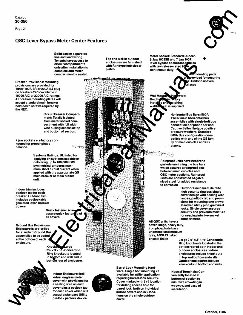
Catalog
30-350
Page 24 Cl OSC Lever Bypass Meter Center Features
Solid barrier separates line and load wiring. Tenants have access to circuit compartments only after installation is complete and meter compartment is sealed.
Breaker Provisions: Mounting provisions are provided for either 1 OOA BR or 200A BJ plug on breakers 240V available in 1 0000 AIC or 22000 AIC ratings: All breaker mounting plates will accept standard main breaker hold down screws required by the NEC.
Circuit Breaker Compartment: Totally isolated from meter socket compartment with full width wire pulling access at top and bottom of section.
7 jaw sockets are factory connected for proper phase balance.
Systems Ratings: UL listed for applying on systems capable of delivering up to 1 00,000 RMS symmetrical amperes maximum short circuit current when applied with the appropriate as main breaker or main fusible unit.
Indoor trim includes padlock tab for each breaker. Outdoor trim includes padlockable gasketed lexan breaker covers.
Quick fastener screws assure quick fastening of all covers
Ground Bus Provisions: Enclosure is pre-drilled for standard Ground Bus assemblies to be added at the bottom of each enclosure.
Knockouts: Large 2112 x 3 x 3112 Concentric Ring knockouts located in bottom end wall and in bottom rear of enclosure.
Indoor Enclosure: Individual ring less meter cover with provisions for a sealing wire on each cover plus a padlock tab for each cover which will accept a standard Utility pin-lock padlock device.
Top end wall in outdoor enclosures are furnished with R1 H type hub closer plates.
Meter Socket: Standard Duncan 5 Jaw HQ5SB and 7 Jaw HQ7 lever bypass socket assemblies with jaw release rated 200A continuous duty.
Raised mounting pads are provided for securing QSC Units to uneven surfaces
Wall Mounting Hardware: Box hanger is factory installed and matching wall bracket is supplied.
Horizontal Bus Bars: 800A 4WSN main horizontal bus assemblies with single bolt bus connection per phase bar and Captive Belleville-type positive pressure washers. Standard 800A Bus configuration compatible with any of the as family of main cubicles and as stacks.
Rainproof units have neoprene gasket!l encircling the bus bars which assures a rainproof seal between main cubicles and QSC meter sections. Rainproof units are constructed of galvanized steel for added resistance to corrosion
Outdoor Enclosure: Raintite high security ringless single cover design with sealing wire lances, padlock tab and provisions for mounting one or two standard utility pin-type barrel locks. Single cover assures security and prevents moisture for seeping into live socket compartment.
All QSC units have a seven stage, heavy duty, iron phosphate base undercoat and medium gray, ANSI 49 baked enamel finish Large 21/2" x 3" x 112" Concentric
Ring knockouts located in the bottom rear of both indoor and outdoor enclosures. Indoor enclosures include knockouts in top and bottom endwalls. Outdoor enclosures include knockouts in bottom endwalls.
Barrel Lock Mounting Hardware: Single bolt mounting kit available for utility application requiring barrel-lock security. Cover marked with ( + ) location for drilling access hole for barrel lock, both on individual indoor covers and in 2 locations on the single outdoor cover.
Neutral Terminals: Conveniently located at bottom of'section to minimize crowding in wireway, and ease of installation.
October, 1 986
www . El
ectric
alPar
tMan
uals
. com

Catalog
30-350
Page 25
OSC Lever Bypass Meter Centers with Jaw Release
Dimensions and Knockout Data appear on pg 33.
QS3CL3BR, M3B4RN, QS3CL2BR, QS3CL1BR
BREAKER METER WALL 200A MAX 0 BALANCE WIRING CTN. STACK POSITION MOUNTING CAT. NO. SOCKET POSITION DIAGRAM WT. STYLE
TOP-7BOTTOM (see pg 33) NO.
1 -HIGH Indoor QSCL 1 B § 1 07
Outdoor QSCL1 BR § 107 1 R
2-HIGH Indoor QSCL2B 8 8 2 1 1 6 2
Outdoor QSCL2BR 8 8 2 1 1 6 2R
2-HIGH Indoor QSCL2BY 8 § 3 1 1 6 2
Outdoor QSCL2BRY 8 § 3 1 1 6 2R
3-HIGH Indoor QSCL3B 8 8 8 4 1 45 3
Outdoor QSCL3BR 8 8 8 4 1 45 3R
3-HIGH Indoor QSCL3BY 8 8 § 5 1 45 3
Outdoor QSCL3BRY 8 8 § 5 1 45 3R
BREAKER METER WALL 200A MAX 0 BALANCE WIRING CTN. STACK SOCKET POSITION DIAGRAM STYLE POSITION MOUNTING CAT. NO. TOP-7BOTTOM (see pg 33) WT. NO.
1 -HIGH Indoor QS3CL1 B 8 6 1 07
Outdoor QS3CL1 BR 8 6 1 07 1 R
2-HIGH Indoor QS3CL2B 8 8 7 1 1 6 2
Outdoor QS3CL2BR 8 8 7 1 1 6 2R
3-HIGH Indoor QS3CL3B 8 8 8 8 1 45 3
Outdoor QS3CL3BR 8 8 8 8 1 45 3R
CD Single phase type QS Main Breaker & Main Fusible Cubicles are factory connected to Phase B and Phase C Main Cross· Busses.
See page 32 for Schematics and Phase Balancing Data.
October, 1 986
www . El
ectric
alPar
tMan
uals
. com
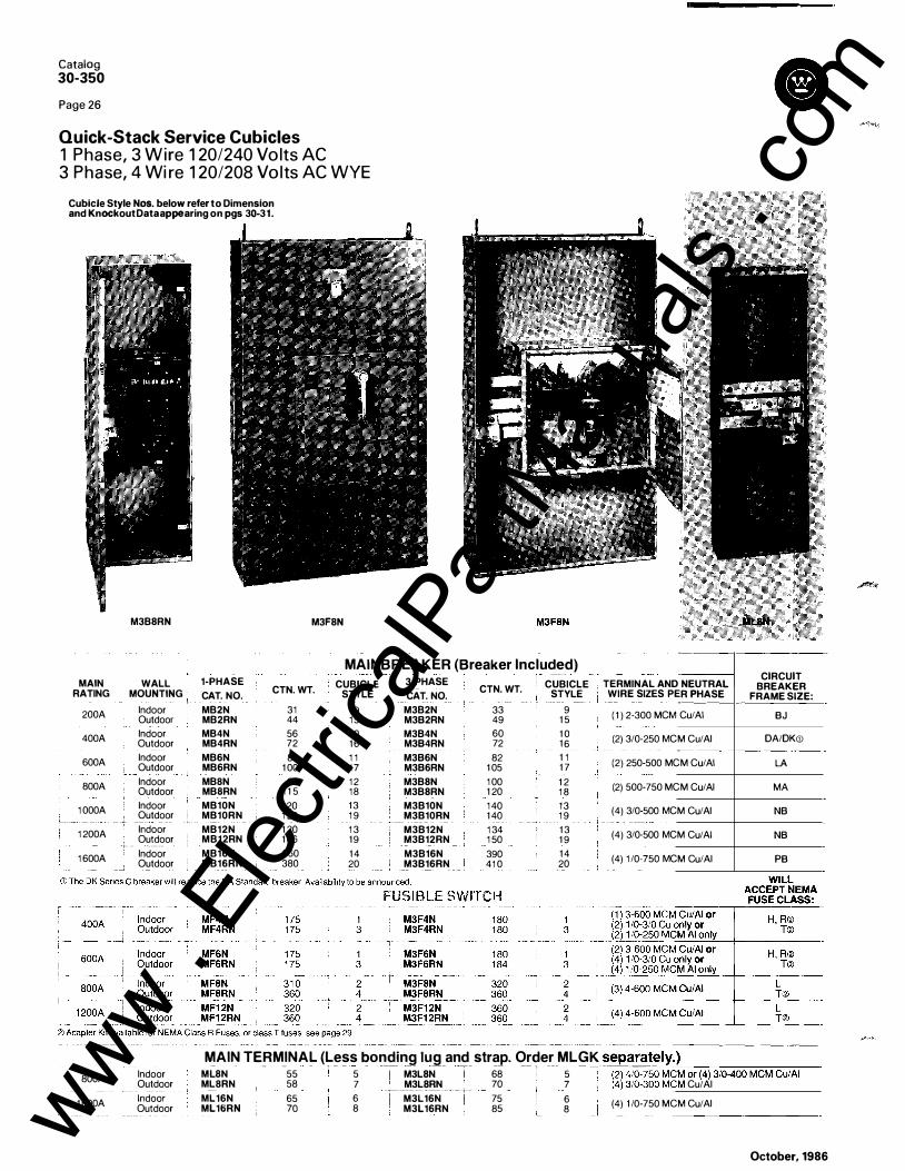
Catalog
30-350
Page 26
Quick-Stack Service Cubicles 1 Phase, 3 Wire 1 20/240 Vo lts AC 3 Phase, 4 Wi re 1 20/208 Vo lts AC WYE
Cubicle Style Nos. below refer to Dimension and Knockout Data appearing on pgs 30-31.
M3B8RN M3F8N
MAINBREAKER (Breaker lnclu�d) MAIN WALL 1-PHASE CUBICLE 3-PHASE CUBICLE
RATING MOUNTING CAT. NO. CTN. WT. STYLE CAT. NO. CTN. WT. STYLE
200A Indoor MB2N 31 9 M3B2N 33 9 Outdoor MB2RN 44 15 M382RN 49 1 5
400A Indoor MB4N 56 1 0 M3B4N 60 1 0 Outdoor MB4RN 72 16 M384RN 72 16
600A Indoor MB6N 80 1 1 M386N 82 1 1 Outdoor MB6RN 1 00 1 7 M386RN 1 05 1 7
800A Indoor MBBN 99 12 M3B8N 1 00 1 2 Outdoor MBSRN 1 1 5 18 M3B8RN 1 20 1 8
1 000A Indoor MB10N 1 20 13 M3B10N 1 40 13 Outdoor ' MB10RN 1 20 1 9 M3B10RN 1 40 1 9
- - I-·-
·
1 200A Indoor MB12N 1 20 1 3 M3B12N 1 34 1 3 Outdoor MB12RN 1 46 19 M3B12RN 1 50 1 9
+-- - ------1 600A Indoor MB16N 360 14 M3B16N 390 14 Outdoor MB16RN 380 20 M3B16RN 41 0 20
-
-TERMINAL AND
WIRE SIZES PE NEUTRAL R PHASE -
( 1 ) 2-300 MCM Cu/AI
(2) 3/0-250 MC M Cu/AI -
(2) 250-500 MC M Cu/AI
(2) 500-750 MC M Cu/AI
(4) 3/0-500 MC M Cu/AI
(4) 3/0-500 MC M Cu/AI
(4) 1 /0-750 MC M Cu/AI
CIRCUIT BREAKER
FRAME SIZE:
BJ DA/DK<D
LA MA
NB NB PB
MAIN TERMINAL (Less bonding lug and strap. Order MLGK separately.) MLSN ' - -55 - , - - - -� -- -- � - -- -- , --- - .... - -�-�- -·'-:----:--::-:c-::--:-:-:--:-:-:::-:-:--::-c-:--800A
1 600A
Indoor Outdoor Indoor Outdoor
MLBRN 58 ---ML16N
ML16RN 65 70
5 7 6 8
M3L8N M3L8RN
-�---- ------ - - --- ---+--M3L16N I
M3L16RN �-�--
68 5 70 7 , _ 75 6 85 8
(2) 4/0-750 MCM or (4) 3/0-400 MCM Cu/AI �- -(4)110-300 MS:M Cu/AI (4) 1 /0-750 MCM Cu/AI
October, 1986
·-
www . El
ectric
alPar
tMan
uals
. com

Cubicle Style Nos. below refer to Dimension and Knockout Data appearing on pgs 30-31.
M3UP8N
Catalog
30-350
Page 27
Quick-Stack Underground Pu ll Sections and Fusible Switches for Use with Westinghouse Bus Duct
M3F4T (shown connected to @ �WAr• Right hand Bus Tap) Left hand tap is also available
I - -------�-
1 I UNDERGROUND PULL SECTION I MAIN I WALL �
-�!_T��� _j__l• M�
-
UNTING I Indoor 400A : Outdoor __________ , _ .... - -Indoor '1 __ _ ���A
--+- Outdoor ! BOOA
t�����--r
CTN. WT.
50 60
1 40 1 40 1 40 1 40 1 70 1 70
G) Supplied without line lugs. 4" KO MAX (Meets EUESR requirements) Ill Order MLGK separately.
CUBICLE STYLE
21 21 22 22 22 22 23 23
FUSI BLE SWITCH ( includes l ine side bus l ink extensions) ---MAIN - -- --r - - --- - - - -
RATING 1 ENCLOSURE ------ - ------i---- ---- - - ------ --- ------��- - ___ _L ____ -- - - -- ��-���
• Main Service cubicles may be applied with either left hand or right hand Bus Tap sections as required by bui lding layout
• QS meter stacks may only be added to one side of the Fusible Switch. (side opposite the Bus Tap flange)
• Bus link extensions are installed and h ardware is packed in the M3F4T,
October, 1986
3-PHASE CAT. NO. M3UP4N M3UP4RN M3UP6N M3UP6RN M3UP8N M3UP8RN M3UP12N M3UP12RN
3 PHASE CAT. NO.
M3F4T M3F6T
CTN. WT.
60 60
1 40 1 40 1 44 1 50 1 90 1 90
M3F6T un its for shipment.
CUBICLE STYLE
CTN. WT. 1 00 1 20
21 21 22 22 22 22 23 23
TERMINAL AND NEUTRAL 1 WIRE SIZES PER PHASE Ill + -
( 1 ) 1 /0-600 MCM Cu/AI or L2) 1 /()-_25()f111_Q_f\11 gu;�- -_ _
(2) 2-500 MCM Cu/AL
(3) 1 -600 MCM Cu/AI or -L6)1 /0-250 f111CM_CtJ/� ----
(4) 2-500 MCM Cu/AI
_____ Jt���� ----�J -- j _ ____ ___ _j
• The rear surface of the Main Service Cubicle aligns with the rear surface of the Bus Tap section.
• List price includes Bus link extensions only. This Bus Tap section must be priced separately with the bus duct. www .
Elec
tricalP
artM
anua
ls . c
om

Catalog
30-350
Page 28
Quick-Pack Meter Centers 1 Phase, 3 Wire 1 20/240 Vo lts AC 22,000 Withsta nd Rati ng
Q P Style Nos. below refer to Dimension and Knockout Data appearing on pg 34.
QP2R1
MAX BRANCH RATING BREAKER SURFACE
METER- MAIN WALL 1 25A 200A POSITIONS RATING MOUNTING CAT. NO. CAT. NO.
2 400A Outdoor QP2R1 QP2BR1
3 400A Outdoor QP3R1 QP3BR1
4 400A Outdoor QP4R1 QP4BR1
5 600A Outdoor QP5R1 QP5BR1
6 600A Outdoor QP6R1 QP6BR1
SR1 snap type nngs included with each socket position at no charge. Select circuit breakers shown on page s. Select Mam Lug Kits from table below. CD Meets EUSER requirements
OVERHEAD FEED
UNDERGROUND FEED
MAIN RATING
200A 400A
600A
200A
400A
600A
600A
e
QP4R1
MAX BRANCH RATING TERMINAL AND NEUTRAL CTN. QP 1 25A 200A CTN. QP WIRE SIZES PER WT. STYLE CAT. NO.CD CAT. NO.CD WT. STYLE PHASE
-------- ---64 QP2WR1 QP2WBR1 80 See Quick-Pack
Main Lug Kits 80 QP3WR1 QP3WBR1 80 Table below
96 2 QP4WR1 QP4WBR1 1 1 0 2
See Quick-Pack 1 20 2 QP5WR1 QP5WBR1 1 20 2 Main Lug Kits
Table below 1 20 2 QP6WR1 QP6WBR1 1 20 2
@ 22,000 AIC rating maintained with BAH or BJH Tenant main breakers. 42,000 AIC rating maintained with BRHH or BJHH Tenant main breakers. See System Short Circuit Rating table page 29.
CAT. NO.
OVERHEAD FEED
QPMLKOH200 QPMLKOH400
QPMLKOH600
UNDERGROUND FEED
QPMLKUG200
QPMLKUG400
QPMLKUG600
STUD MOUNTING KIT
QPMCK6
TERMINAL AND NEUTRAL WIRE SIZES PER
PHASE ( 1 ) #6-300MCM Cui AI ( 1 ) 4i0-750 CuiAi or (2) 3i0-400 MCM AI (2) 3i0-300 MCM Cu (2) #2-500 MCM Cui AI or ( 1 ) #2-500 MCM Cui AI ( 1 ) #2-600 MCM Cui AI
( 1 ) #6-300 MCM ( 1 ) 4i0-750 Cui AI or (2) 3i0-400 AI (2) 3i0-300 Cu (2) -#2-500 MCM Cui AI or ( 1 ) #2-500 MCM Cui AI ( 1 ) #2-600 MCM CuiAI
Utility Furnished Compression Type Lugs
October, 1986
.. �-
www . El
ectric
alPar
tMan
uals
. com

DESCRIP-'-T,I-=0-'-N:_ __ _____________ -i For additional clearance between service cubicle and r igh-hand mounted meter socketbreaker sections. NEMA-3R .
CLASS R FUSE '(I r FOR MF FUSIBLE SWIT\H SERVICE C U BICLES
I' '! e � ! �:::��-�,; .. <00 ;}::c:7,�:,, s�� ---�-� _ �--- clesto accept onlyCia:�
-� �u
_ses: _ i
MAIN TERMINAl EQUIPMENT GROUND LUG
[� [ ��A�:o� ; (;;����:.��nd::s5�;�1�N��--=---=-==l SEALING RINm ��
-, - -·----�---�-- -------- ---�----- ---- --- - -----1 u 0 r- �i��- N().
j_J>;��-T;�A�;���f!I_F'TION _ _ � l
L __ g __ �l :;,_ 1 ;,:;��:�: .. ,.,___ ..• � • H U BS --� - ---------,--- -� -- - - ----- ------ - - -�- ���� ------�-!!l):_s�z5_ _ _
-=--==·=a�J � R1H250 2W' --�-l_ _ R1H300 --�--�----3
CLASS 'T" ADAPTER KITS FOR M FUSIBLE SWITCH SERVICE CUBICLES �1-��-, �0 �· ��·�·rrrg��� 1 ������ r - --- -
D���;;TI;N---,
. 400A FDP4T -l3FDP4T ! [ 600A FDP6T I 3FDP6T j Converts MF, M3F, Fusible i 0 0 0 o• ,, 0 I BOOA I FDP8T i 3FDP8T 'I to Accept Class T Fuses L � L-� . _ 1 �00�DP1 2T
L_3�[)_F'_1_2_!_L ____ __ _
SYSTEM SHORT C I R C U IT RATI N G : Use this table to select the right combination of metering equipment to meet the available fault current AIC requirements. The complete meter center assembly rating applies only with main and branch devices listed on the
Catalog
30-350
Page 29
Meter Center Accessories and System Short Circu it Rating Table
CORNER SECTION �- ,. �� �---,. -�--- -- - -- - T · - --- --- --� - -------- I I � ;::� -------; .f ! CAT. NO. i DESCRIPTION f���- I ���: 1 �\ ��������� : -- -QSCS ___ r������f�����������=��---- 1 1 1 : \ _ j" �l_v r 1 cubicle and stack units in corner i I "'- _ _ ':_j_ ____ �stall<!lron:__c:;Q111�r t�_corner _1 4_'_' -'-! __ _�_ __ 5TH AND 6TH JAW KIT
CAT. NO. i DESCRIPTION
MMSJK �eter C�-;;jers (aP,as) an--d-t-----t------1
i UB, OB, UP. j For use with 200 Amp. max. 3 � __ __j_l_a_nd/or_9_o_'c_l�k po:itions
MAN UAL BY-PASS KIT .. --�----r- -T-f����:ufF�r QP-���s�;���:�:nly-200 I ���- I ���: I 1 1 Amp. max. I 1 1 0 1 - 1
_ 1 For factory i nstal l at ion add 1 I L _____ � ___ _l_ 1 $2.00 list each
__ _LI __ L_ _ _j_
GROUND BAR KITS FOR QS STACKS · (See pg. 1 8 for wire size) �----�-���-NO
-. -� NO. OF TERMINALS ---'---� I , - - -- -+--- -- - -- 1
l ...... ·1/(" I GB3 i 3 �I I ,. I - -- r- --- �-
J Q - -• 1 GB3A : 3 I
f--�-�-----t� ---�� - -------
1 � GB6A I- 6 ___ _
l� _ _ ___ ___ l _ GB_6 __ j 6 Q) QP Meter Centers have ground terminals included with neutral terminations 1n each breaker compartment
BARREL LOCK MOUNTING KIT
I f\ ,
G) CAT. NO.
BLK
DESCRIPTION � For OSC Lever Bypass __jl Meter Centers
wiring diagram. All series-combination ratings have been extensively tested at the Westinghouse High-Power Test Lab, and are listed by U.L. for the amperage interrupting capacities shown.
r-:--��- - ----�---- --- ---- --� --,�- --�-�------� I I Available Fault Current At L1ne Ma1n Serv1ce Cub1cle - M1n1mum Braker ! OS Stack - Tenant Main Breaker 1 Load Centers - Branch I Complete Meter Center . Terminals of Assembly - RMS Frame S1ze Requ1red 1 Requ1red ' Breaker Requ1red Assembly Short CirCUit Rating
Symmetrrcal Amps (dJ 240 VAG Max 1 1 - RMS Symmetrrcal Amps (!I + I =t
240 VAG Max. � I To 10,000 A.
- -�--=-=----- All standard MB, MF - -�BR,-BJ----�=--=-=--��--- �-:Bo-� 10,000 AIC I 10,001 to 22,000 A. All standard MB, MF or ML Cubicles .i BRH, BJH except when
.
us
.
ed
.
w
.
ith
.
MB2 ! BR, BD, BQ I 22,000 AIC-II
except the MB2 series, which requires I series with BJH2200; then BR, BJ �o
o
-
.
0
0�1
1�:t
o
o
-4
6
-2
5,,
0
0
0
0
0
0:A_·_ ·�
--
- - ----
-
��H;�;:;::;������c��SB and PB �
-BRH."BJH -- --- - -- - u • - - - -- �-8R,"8D,
BQ I 42,000 AIC '
MB4 units with DK Series C breaker. iBfiH.B'JH-�--- --- ---- -�-- I BRD, BD, BQ 65,000 AIC 001 to 65,000 A. ----
MB units with special HLA, HMA. HNB---� BRf.;-------�-�------:--s-R. BD, BQ 65,000 AIC I 1 and standard PB Frame breakers. j (1 00 Ampere Max). j I 1 42,
oo1io 100,000A� --k'��:i�n:�hCia�;-T fu��-and-FDPT �H, BJH ---- - -� . -----���BD, BO-
----t 100,000 A-IC-------l
1 f
s·��1�-
2��
·�:
A� ! ��:;��;;����
-fr�m
-
e�r::ke_r_s
----���-�:
H�B��:--
-
-�=-���=--
--�-
--i
-��=·-
B_o_. �� --_ -�f-� -2-oo_._oo_o_A_I_c _____ ----i· I I QP Meter Center Tenant Main Breaker i !
I To 10,000 A N/A rBR.s"J _ _______ --- . .I '"· eo, 00 I ,.., ...
1�·.:� ��!�·.���A _ _______ 1��----� - --u·---- -- I ��;,�H�-- -- -- - · __ _ l_ �-�L_��'-':-'-��:_:�_: ______ __j All devices comply with the 22.000 AIC-1 0,000 AIC U.L. Series Connected Components file DKSY2 of the Recognized Components Index.
October, 1 986 www . El
ectric
alPar
tMan
uals
. com

Catalog
30-350
Page 30
Quick-Stack Meter Center and Service Cubicle D i m e nsions a n d Knockout Locatio n s
j_@- ��-l ' F F • 10 EJ ,,, ,,, # I I I 1' ! f-- 227!8 ----1 j__ 0 0 � 0-4 107/a
31/a TYP. � _l_ T f-- 323/a -----j CUBICLE 1 CUBICLE 2
·+ - : . T _)_ _I_ 0 1 1 0 rr=� r
• 43 • 43
"+ �_:' 1 0
"+ : · 1 CUBICLE 5
OS DIMENSIONS -- - - -- - -------- -I INDOOR NEMA 1 - l I RAINPROOF NEMA 3R I r- ---- -,---- ____ ___j
[ WIDTH _ _ 1 HEIGHT_ _ __ j_ _ _ DEPTH T - -;;�� -- r- - , 291/4
1 21/a 381/4 1 21/a 471/4 1 21/a 561/4 1 21/a 651/4
Top and Bottom are typical of all OS stack units.
63/a 63/a 63/a ' 63/a I 63/a _
_ _J ----- --- -·------ - - --------------------
0
, - - - - - - 1 ' ' '
,�;/��� :
' '
' I
L _ _ _ _ _ _ j
46112
u_-_:_�-----,��r _l_
CUBICLE 3
0 54112
� �
JBICLE 4
[0-� �
23/4 I �D fr D D D D I
Fie OS-6R
QUICK-STACV IETER CENTERS
KNOCKOUTS
A -- 1 - - - ---1/2
B c - ----r - -- ·-1/2 1 3/4 1 1/4 __ , ______ __ _
2
D
1 1/4 1 1/2 2
E F G H -1 1/2 2 21/2 3 -2 21/2 3 31/2 -
21/2 3 31/2 4
October, 1986
www . El
ectric
alPar
tMan
uals
. com

29/32
!�;.c. � __j__ I CUBICLf 1 5 2,1,6 CUBICLE 1 6
I --;·-
Catalog 30-350
Page 31
Quick-Stack Service Cubicle and Accessory Di m ensions a n d Knockout Locatio n s
rMMl �
f-- 15 --j f-- 15 ---1 1--- 17"1• ----1 1--- 22'1• ------1
:- ,,,�; r · · . 1 . r ·· 9T ' ";· 1 c 1 � 44'12 _ , - , I
u__________j l . . I I : i 169 2"{'" �T L_____ "----------
lJ____________.� (c
��· 7· T 3I + -IT TcuBICLE 1 7 !-rf\!'"1 l ��m2 2'12 ==== -� f ... f 1.!-1 �l_l j T I T � -� _l
_,_ r 2'51,. 1sr32 2'1• ! �___,_____,_____,..,_,.J CUBICLE 18 CUBICLE 19 T 215116 CUBICLE 20
�T I 1 17'/s l"� _ j !
14
3
_L[_��
TI �.
+ -: l '----------'
� �- � rS'ho-j
l_sf � r-- 14-----j ascs QSSKR
QUIC K�STACK ACCESSORIES Tf--155fe --j
October, 1 986
www . El
ectric
alPar
tMan
uals
. com

Catalog
30-350
Page 32
QSC Lever Bypass Meter Center Schem atics a n d Phase B a l a n c i n g Data
A B C
--+-+-t---eA ---�----f-----tl� B ---"J.-1..----+----ji-¥-.. N �f
DIAGRAM 1
DIAGRAM 5
A B C _ ___.-+-t----e A --+=+-�=-tt-e 8 --"'4--+---tJ� N �::'::j::::::::j=t'--..1. c
DIAGRAM 2
A B C
--+=+=�� B ---'+++-+++�� N ---++��--- c
• = Neutral
( Potent ia l J aw)
DIAGRAM 6
A B C --------+-+---___. A ->-+----+----Hre B ----'.1+--+--t:J.� N �=1==1:�---!...C
DIAGRAM 3
A B C
-------t-+__._+----H.-. B ........ -'H--H*-1-;1'-� N .m:+4+-� c
• = Neutral
( Potent i a l J aw)
DIAGRAM 7
[ I AGRAM 4
• = Neutral (Potential Jaw) DI �GRAM 8
S ELECTION A N D APPLICATION FOR PHASE BALANCING QSC METER STACKS . . . . . . coordinate them with any of the single phase Main Breaker QSC stack selection for application of 5Jaw
. Single. phase
(MB) or Main Fusible (MF) cubicles which are also factory sockets on single phase 3wire and 3phase 4wlre services.
connected to phases B-C. QSC 5jaw socket stacks are fa�tory-bussed and con.nec
.ted to 2. If the service bus is 3phase 4wire 1 20/208VAC MAX, apply
the main cross-bus. By select1ng th� proper combination of any combination of single, two or three unit stacks con- �.
stacks, the complete meter center Wil l be properly balanc�d, nected to phases A-B, B-C, and C-A. (Example: a 9-unit
distributing .the .individual metered loads evenly on the serv1ce
apartment would be perfectly balanced with 3 sockets on bus. Select1on IS as follows:
A-B, 3 sockets on B-C, and 3 sockets on C-A). Of course, 1 . If the service bus is single phase 3wire 240VAC MAX, when the total number of apartment units is not in multiples
apply only stacks with sockets connected to B-C. This wil l of 3, select the stacks which wil l minimize the imbalance.
October, 1 986 www . El
ectric
alPar
tMan
uals
. com

rr-·- L�tter- � -'-. ---=A. - �- f-l .. · ;�-;------ -- ! 1f2
-------
. -· ·· · .
3 I co�duit i . . .. .... j ----· Stze c---··-·- [ 3112 I - -
~
I 0 () 1 [
~ A
STACK 1
' EJ
I I J
STACK 1 R
October, 1986
INDOOR
D 0 45'h•
D
!�® I A
STACK 2
OUTDOOR
[®?@ 1 A
STACK 2 R
Catalog
30-350
Page 33
B ass Meter Center OS� Lever d �p ockout Locat ions D i m e n s i o n s a n n
(4) Mtg. pads with 9/32 dia. hole
r ,o l
0
D
STACK 3
r�®l A
STACK 3R
www . El
ectric
alPar
tMan
uals
. com

Catalog
30-350
Page 34
Quick-Pack Outdoor Meter Centers D i mensions a n d Kn ockout Data
2 & 3 METER
QP STYLE 1
H
KNOCK< UTS ------- -
Letter A B --
--- --+--- -
-
1/2 : 1/2 Conduit - 3/��--Size ; __ +=_1_ _
1- � -
____ __l___ l
ENCLOSURE HEIGHT QP STYLE 1
�AT. NO. H QP2R1 QP2BR1 293/e QP2WR1 QP2WBR1 QP3R1 QP3BR1 383/s QP3WR1 QP3WBR1
I
I I I
�----- ______ ____J
c D 2 3 -
21/2 31/2 -3 4 -
· P STYLE 2
-
-
-
CAT. NO. QP4R1 QP4BR1 QP4WR1 QP4WBR1 QP5R1 QP5BR1 QP5WR1 QP5WBR1 QP6R1 QP6BR1 QP6WR1 QP6WBR1
4, 5 & 6 METER QP STYLE 2
E 1
1 1/4 1 1/2 2
H
293/s
383/s
H
October, 1986
www . El
ectric
alPar
tMan
uals
. com

LINE I I
r - J I I
I 1 I I I I I � -""= I
, � , � 21 2 ·�
,- - - - - - - - - - LINE
: �D- -J ! _ _ _ .J
[ID -��-·�--� - � -� �
P 1 :i 20N
24-406' I
B24-40B: !
October, 1986
LINE
2-4-50
2-4-60
- LINE
1 2 ·24N
1 2-24AN
1 2-24BN
- - - - - - - LINE
' ' ' I '
-J
B30-30AN
B-1 4-20N
30-40EJN
B30-40BN
' ' ' ' ' ' _ _ J I ' _ _ _ _;
LINE
B1 6-20N
20-30AN
B20-30AN
40-40BN
B40-40BN
Catalog
30-350
Page 35
1 Phase Main Breaker .
Only Schematics to ���M A
am Lug
- - --mperes
LINE rn��· _ _ J j [ 125A _ :
- - -
-' : . J ' - [Sl -�� � -� - 200A
-�-8-1 6BN
B8-16N
- LINE : '
- - - - - - - - - LINE
' ' ' ' _ _ _ .J : _ _ _ _ _ J
1 6-24N
B1 6-24KN
-�
LINE ' ' ' ' ' ' J ' '
' : _j :
rn
20-40BN
B20-40BN
B20-40CN
42-42CN
B42-42CN
LINE ' ' ' ' ' ' -' ' ' ' ' ' ' __ ..J I
B1 0-20N
- �!NE ' ' ' ' .J : '
1 6-30AN
B1 6-30AN
- - - - - - - LINE _ _ .J I ' - - _ ....J
B24-30AN
:=f] --' : _ _ _ ...J
MAIN BREAKER OR MAIN LUG DEPENDING UPON CATALOG NUMBER
J\__ BR PREFIX BREAKER
� BD PREFIX BREAKER
- FACTORY WIRING � - - -- FIELD WIRING
www . El
ectric
alPar
tMan
uals
. com

Cata log
30-350
Pag e 36
Main Breaker and Main Lug Schematics
LINE �:� 3 1 00N
3-1 2-24N
3-1 2-24BN
3B-1 2-24N
LINE
LINE
-.�� - , " I , , - , _
- ..J - "I. J ... - '- -
_ ,..-_ .... .., I ... ... -_� -
- J "- .... -" .._ -
_ .... - \... _ _ .. -.... -
3-1 8-36AN
3-1 8-368N
LINE
1 2-24DN
1 2-24EN
LINE
L - - - _j B24-42DN
3-24-42AN
3-24-42BN
LINE I I I
�
LINE
I
L _ _ _ _J 24-42DN
24-42EN
LINE I I
� I L _ _ _ j
830-42DN
LINE
3-30-42BN
3B-30-42AN
3B-30-42BN
m
3-36-42BN
LINE I 1 I ' I I I I I
[lliJ L _ _ _ _ .J
3-1 8-36DN
LINE I I I
I
[}EJ L _ _ _ __j
3B-30-42DN
LINE _, , . ' - � : : _ _ j I
I
m LINE
m-f1 l ;t-t J �c � �- �
-"-+' -� rc ,
* � � �
38-42-428N
I
LINE I I I I 1 I I I
S N I L _ _ _ ...J
3-42-4 I)N 3-42-4 I:N
LINE I I I '
I I
I I
� L _ _ _ _ _J
38-42-4: CIN 38-42-4: E:N
LINE
3-42-42CN 3B-42-42CN
October, 1986 www . El
ectric
alPar
tMan
uals
. com

ALT. LINE N
LINE N
LINE R8-161M
UN2BROM
October, 1986
UP2BLNFROM UP2BLNROM
I I I I I I
LINE
UBN1 2-24FR UBN1 2-24R UBN1 2-24KFR UBN1 2-24KR
Cata log
30-350
Page 37
Riser/Feed-Thru Panel and Meter Socket Panel Schematics
ALT. LINE N
' ' ' ' '
.,
R1 2-241M R1 2-24BIM
J U�-. · ·. I I I
I I - . �- . I I I "i' : .
..
I I I I 1 1 I I L f-- _ + _ -1- -c===srr=-:=-J
ALT. LINE : : : ' ' ' I ' '
- - - - - ��� : : \ ' '
LINE R16-241M
' ' ' 8' ;:
i'--�< i
- _,___::�' ' ' ' ' ' I
~ •• : : � �
' ,, ; : ' '
LINE N
UNBROM
' ' ' ' ' ' ' ' '
� I I I ' '
ALT.
UNBL20RO
OBN1 2-24RO OBN1 2-24FR OBN12-24KRO
LINE
UBN1 6-24KR UBN1 6-24KFR
LINE
LINE
: : : @] I I I
LINE N
UPBLNFROM UPBLNROM
OBN1 6-24FR OBN1 6-24RO OBN1 6-24KFR OBN1 6-24KRO
LINE
UBN20-40AFR UBN20-40BFR UBN20-40AR UBN20-40BR
R20-241M
I I I ' 1 I 1 I I I I
LINE N
c L GND.WHEN REQ"O.
UP2BLN20FR UP2BLN20R
OBN20-40BFR OBN20-40BRO OBN20-40AFR OBN20-40ARO
SIGNIFIES 1 " TYPE BREAKER -c=J SIGNIFIES DUPLEX
TYPE BREAKER -f:3 www . El
ectric
alPar
tMan
uals
. com

Catalog
30-350
Page 38
Typical Meter Center Schematics
c ·� QS-2
B --"'"I:::::J>;;.<---p;l----e
N .--�-------H-e c -���------e
LINE N I
I I N I
1 LINE 1
QP2R1 QP2WR1
•
B -�:::I>"''---::F.7--e N ---+-+-----1+-e c -��------
B -�::IP"'--;:1?'-;::;--.. N --+-+----tt-e c -��------
QUICK-STACK METER CENTERS
LINE N
I N
I LINE I Q?F�Ri GP5\tVR i
LINE N
N I LINE I
QP3R 1 QP3'NR"'�
QUICK-PACK METER CENTERS
B --"'"��-�� ..
N --�-----� .. c -���--��
LINE ' I I I
• i ra ; � L Neuttal ;• petmanently bonded MB4
LINE I r
$ r
¢ • I N o I r @ihl ' ¢ • r ¥ r '
r LINE ML8
LINE
QUICK-STACK SERVICE CUBICLES
LINE
N I LINE 1
QP4 R 1 QP4W'
LINE N I
Qi'fiR1 QP6WR1
October, 1986 www . El
ectric
alPar
tMan
uals
. com

8 Catalog
30-350
Page 39
Nu merical Index
CAT. NO. PAGE CAT. NO. PAGE CAT. NO. PAGE CAT. NO. PAGE CAT. NO. PAGE CAT. NO. PAGE CAT. NO. PAGE CAT. NO. PAGE
8011 8 80C230·230 8R2110 842-42CSN 1 0 MUP4RN 27 OS3CL28 25 08N12-24KRO 1 9 30-408SN 1 2 8010·10 6 80C230·240 8R2125 842-420FN 1 0 MUP6N 27 OS3CL28R 25 08N12-24RO 1 9 3100FLN 1 3 8015-15 6 80C230·250 8R215 842·42DR1N 10 MUP6RN 27 OS3CL38 25 08N16·24FR 1 9 3100RDN 1 3 8015-15HACR 6 80C240·2115 8R215H 842·420SN 1 0 MUPBN 27 OS3CL38R 25 08N16-24KRO 1 9 3100SLN 1 3 8015-20 6 80C240·2120 8R220 842·42EFN 1 0 MUPBRN 27 OS·3R 23 08N16·24RO 1 9 3-12·24BFN 1 3 8015·20HACR 6 80C240·240 6 8R220H 6 B42·42ER1N 1 0 M3810N 26 OS-4 23 08N20-40AFR 1 9 3-12·248R1N 13 8015-30 6 80C240-250 6 8R225 5 B42·42ESN 1 0 M3810RN 26 OS·4A 23 08N20-40ARO 1 9 3·12-248SN 1 3 8020-15 6 80C250·2115 6 8R230 5 88·16FN 1 0 M3812N 26 OS·4AR 23 08N20-408FR 1 9 3·12·24FN 1 3 BD20·15HACR 6 80C250·2120 6 8R230H 6 88·16FNG 1 4 M3812RN 26 08·48 23 08N20-408RO 1 9 3-12-24RON 1 3 8020-20 6 80C250-250 6 8R240 5 88·16RON 1 0 M3816N 26 OS·48R 23 12·24AFN 1 2 3-12·24SN 1 3 8020-ZOHACR 6 80215-215 6 8R240H 6 88-16SN 1 0 M3816RN 26 OS·4R 23 12-24ARON 1 2 3·18·36AFN 1 3 8020-30 6 80220·220 6 8R250 5 88·16SNG 1 4 M382N 26 OS-5 23 12-24ASN 1 2 3·18-36AR1N 1 3 8025-25 6 80220·230 6 8R250H 6 co 1 8 M382RN 26 OS·5A 23 12-248FN 1 2 3·18·36ASN 1 3 8030·15 6 80220·240 6 8R250NA 6 C01 1 8 M384N 26 OS·5AR 23 12·248R1N 12 3·18·368FN 1 3 8030·15HACR 6 80220·250 6 8R260 5 DLM 1 8 M384RN 26 OS·5R 23 12·248SN 1 2 3·18-368R1 N 1 3 8030·20 6 80225-225 6 8R260H 6 DL3 1 8 M386N 26 08·6 23 12·24DFN 1 2 3·18-368SN 1 3 8030·20HACR 6 80230-2115 6 8R260NA 6 EOHOS 1 8 M386RN 26 OS-6R 23 12·240R1N 1 2 3-18·36DFN 1 3 8030-30HACR 6 80230-2120 6 8R270 5 FDP12T 29 M388N 26 RD12EM 1 7 12-24DSN 1 2 3-18·36DR1 N 1 3 8030·30 6 80230·230 6 8R270H 6 FDP4T 29 M388RN 26 RD12FCM 1 7 12·24FN 1 2 3-18·36DSN 1 3 8030-50 6 80230·240 6 8R280 5 FOP6T 29 M3F12N 26 R016EM 1 7 12-24FNG 1 4 3·24-42AFN 1 3 8050-30 802311-250 8R290 FDPBT 29 M3F12RN 26 RD16FCM 1 7 12-24SN 1 2 3-24-42AR1N 1 3 BHGW 80240-2115 8R3030 FP1 1 8 M3F4N 26 R020EM 1 7 12-24SNG 1 4 3-24-42ASN 1 3 BHLW 80240·2120 8R3100 FP18 1 8 M3F4RN 26 R020FCM 1 7 16-24FN 1 2 3·24-428FN 1 3
80240-240 8R3100NA G810 1 8 M3F4T 27 R08EM 1 7 16·24RON 1 2 3·24-428SN 13 80240-250 8R315 G814 1 8 M3F6N 26 RD8FCM 1 7 16·24SN 1 2 3-24·42DFN 1 3
8HT 8 80250-2115 8R320 G818 1 8 M3F6RN 26 RFK666 29 16-30AFN 12 3-24-420R1 N 1 3 8H12·20FN 1 0 80250-2120 8R330 G822 1 8 M3F6T 27 ROH075 1 8 16-30ARON 12 3·24-42DSN 1 3 8H12·20SN 1 0 80250-250 8R340 G83 1 8 M3F8N 26 ROH100 18 16·30ASN 1 2 3-30·428FN 1 3 8H16·20FN 1 0 8RDC215-215 8R350 G83A 1 8 M3F8RN 26 ROH125 1 8 20-24FN 1 2 3·30·42BR1 N 1 3 8H16-20SN 1 0 8ROC230·230 8R360 G86 1 8 M3L16N 26 ROH150 1 8 2D·24RON 12 3·30·42BSN 1 3 BH16-30AFN 1 0 8ROC230·240 BR370 G86A 1 8 M3L16RN 26 ROH200 1 8 20-24SN 1 2 3·36·42BFN 1 3 8H16·3DASN 1 0 8RDC230-250 BR390 GFC8H115 5 M3L8N 26 R1HA 1 8 20-30AFN 1 2 3·36-428SN 1 3 8H20-20FN 1 0 8RDL 8R415 GFC8H120 5 M3L8RN 26 R1H200 18 20-30ARON 1 2 3-42·428FN 1 3 8H20-20SN 1 0 8R0230·240 BR420 GFC8H125 5 M3UP12N 27 R1H200S 1 8 20-30ASN 12 3·42·428R1 N 1 3 8H20·30AFN 1 0 BRD230·250 8R430 GFC8H130 5 M3UP12RN 27 R1H250 29 20-408FN 1 2 3·42-428SN 1 3 8H21l-30ASN 1 0 8RHDS 1 8 810-20FNG 1 4 GFC8H215 M3UP4N 27 R1H250S 1 8 21l-40BR1N 1 2 3-42·42CFN 1 3 8H20·408FN 1 0 BRHDSS 18 B10·20SNG 1 4 GFC8H220 M3UP4RN 27 R1H300 1 8 20-40BSN 1 2 3-42-42CR1 N 1 3 8H20·408SN 1 0 8RHH2100 5 812·20FN 1 0 GFCBH225 M3UP6N 27 R12EM 1 7 2125FLN 1 2 3-42·42CSN 1 3 BH24-30AFN 1 0 8RHH2125 5 812·20FNG 1 4 GFC8H230 M3UP6RN 27 R12FCM 1 7 2125RON 1 2 3·42-42DFN 1 3 BH24-30ASN 1 0 BRH115 5 812-20RON 1 0 GFC8115 M3UP8N 27 R12-241M 1 7 2125SLN 1 2 3·42·42DR1 N 1 3 BH24·408FN 1 0 BRH120 5 B12·20SN 1 0 GFC8120 M3UP8RN 27 R16EM 1 7 24-30FLN 1 2 3-42·42DSN 1 3 8H24-408SN 1 0 8RH125 5 812·20SNG 1 4 GFC8125 PS49 1 8 R16FCM 1 7 24-30FLNG 1 4 3-42·42EFN 1 3 8H30·30AFN 1 0 BRH130 5 812·248FNG 1 4 GFC8130 OHL 8 R16-241M 1 7 24-30SLN 12 3·42-42ER1N 1 3 BH31l-30ASN 1 0 8RH140 5 812·248SNG 1 4 GFC8215 OPMCK6 28 R20EM 1 7 24-30SLNG 14 3-42·42ESN 1 3 BH31l-408FN 1 0 8RH150 5 816-20FN 1 0 GFC8220 OPMLKUG200 28 R20FCM 1 7 24-408FN 1 2 40·40BFN 1 2 BH30·40BSN 1 0 BRH160 816·20RDN 1 0 GFCB225 OPMLKUG400 28 R20-241M 1 7 24-408R1N 1 2 40-408R1N 12 BH40·40BFN 1 0 8RH170 816·20SN 1 0 GFC8230 OPMLKUG600 28 R8EM 1 7 24-408SN 1 2 40·40BSN 1 2 BH40·408SN 1 0 8RH2100 B16·24KFN 1 0 GFEP115 OPMLKOH200 28 RBFCM 17 24-42DFN 1 2 42·42BFN 1 2 BH42·428FN 1 0 BRH2110 816·24KSN 1 0 GFEP120 OPMLKOH400 28 R8·161M 24-42DR1N 1 2 42·42BR1N 1 2 BH42·42BSN 1 0 BRH2125 B16-30AFN 1 0 GFEP125 OPMLKOH&OO 28 SBR1 29 24-420SN 12 42-428SN 1 2 BH42-42CFN 1 0 BRH215 B16·30AFNG 1 4 GFEP130 OP2BR1 28 SR1 29 24-&0FLN 1 2 42·42CFN 1 2 BH42·42CSN 1 0 BRH220 B16·30ARON 1 0 GFEP215 OP2R1 28 STSR1 29 24-60FLNG 1 4 42·42CR1N 1 2 BJHDS 1 8 8RH225 816·30ASN 1 0 GFEP220 OP2WBR1 28 S6·12FLN 12 24-60RDN 1 2 42·42CSN 1 2 BJHDS3P 1 8 8RH230 816·30ASNG 1 0 GFEP225 OP2WR1 28 S6·12FLNG 1 4 24-&0SLN 1 2 42·42DFN 1 2 8JHH2150 5 8RH240 B16·328FN 1 0 GFEP230 0P3BR1 28 S6-12FN 1 2 24-60SLNG 1 4 42-42DR1N 1 2
BRH250 816-328FNG 1 4 GT2500 1 7 OP3R1 28 S6·12FNG 1 4 3BH12·24FM 1 1 42·42DSN 1 2 BJHH2200 BRH260 816·328SN 1 0 GT250·250 1 7 OP3WBR1 28 S6·12RON 1 2 3BH12·24SN 1 1 42·42EFN 1 2 BJH2125 BRH270 816·32BSNG 1 4 GT500·250 1 7 OP3WR1 28 S6-12SLN 1 2 38H30·42AFN 1 1 42-42ER1N 1 2 BJH2150 8RH290 B20·20FN 1 0 HLW 8 OP4BR1 28 S6·12SLNG 1 4 3BH30·42ASN 1 1 42-42ESN 1 2 8JH2115 8RH3100 B20-20RON 1 0 M8P 29 OP4R1 28 S6·12SN 1 2 3BH30·428FN 1 1 8·168R1N 1 2 8JH2200 5 8RH315 820·20SN 1 0 MB10N 26 OP4WBR1 28 S6·12SNG 1 4 38H30·428SN 1 1 BJH2225 5 8RH320 820·24KFN 1 0 M810RN 26 OP4WR1 28 S8·16FLN 1 2 3BH42·42BFN 1 1 BJH3125 5 BRH330 B20-24KRON 1 0 M812N 26 OP5BR1 28 S8·16FLNG 1 4 3BH42·42BSN 1 1 BJH3150 5 BRH340 B20·24KSN 1 0 M812RN 26 OP5R1 28 S8·16FN 1 2 38H42·42CFN 1 1 BJH3175 5 8RH350 820-30AFN 1 0 M816N 26 OP5WBR1 28 S8·16FNG 14 38H42-42CSN 1 1 8JH3200 5 BRH360 5 B20-30ARON 1 0 MB16RN 26 OP5WR1 28 S8·16RON 1 2 3812·24FN 1 1 BJH3225 5 BRH370 5 B20·30ASN 1 0 MB2N 26 OP6BR1 28 S8·16SLN 1 2 3812·24RON 1 1 BJ2FN 1 2 BRH390 5 820-40BFN 1 0 MB2RN 26 OP6R1 28 S8·16SLNG 1 4 3812·24SN 1 1 BJ2R1N 1 2 BRLW 8 B20·40BFNG 1 4 MB4N 26 OP6W8R1 29 S8·16SN 12 3830-42AFN 1 1 8J2SN 1 2 BROLW 8 B20·40BR1N 1 0 MB4RN 26 OP6WR1 29 S8·16SNG 14 3830·42AR1 N 1 1 BJ2125 5 BRSN215 6 B20-40BSN 1 0 M86N 26 OSCL18 25 THSl 8 3B31l-42ASN 1 1 BJ2150 5 BRSN220 6 820·40BSNG 1 4 MB6RN 26 OSCL1BR 25 THOW 8 3831l-42BFN 1 1 BJ2175 5 BRSN230 6 B24·30AFN 1 0 MBBN 26 OSCL2B 25 TT120FLNG 14 3830·428R1 N 1 1 BJ2200 5 8RWH215 6 B24-30ASN 1 0 MB8RN 26 OSCL2BR 25 TI120SLNG 1 4 3830·42BSN 1 1 BJ2225 5 8RWH220 6 824-40BFN 1 0 MF12N 26 OSCL2BRY 25 UBN12·24FR 1 9 3830·42DDFN 1 1 BJ2225NA 6 8RWH230 6 824-40BFNG 1 4 MF12RN 26 OSCL2BY 25 UBN12·24KFR 19 3830-42DORN 1 1 BJ3FN 1 3 8R110 5 824·40BR1N 1 0 MF4N 26 OSCL3B 25 UBN12·24KR 1 9 3830·42DDSN 1 1 BJ3R1N 1 3 8R115 5 824-40BSN 1 0 MF4RN 26 OSCL3BR 25 UBN12·24R 1 9 3842·428FN 1 1 BJ3SN 1 3 8R115HACR 5 B24·40BSNG 1 4 MF6N 26 OSCL38RY 25 UBN16·24FR 1 9 3842·42BR1N 11 BJ3125 5 8R120 5 B30-30AFN 1 0 MF6RN 26 OSCL3BY 25 UBN16·24KFR 1 9 3842-428SN 1 1 8J3150 8R120HACR 5 830·30ASN 1 0 MF8N 26 OSCS 29 U8N16·24KR 1 9 3842·42CFN 1 1 BJ3175 BR125 5 B30-40BFN 1 0 MF8RN 26 OSSKR 29 UBN16·24R 1 9 3842·42CR1N 11 BJ3200 BR130 5 B30·40BR1N 1 0 MLGK 29 08·2 23 U8N20·40AFR 1 9 3842·42CSN 1 1 BJ3225 8R130HACR 5 B30-408SN 1 0 MLK2150 1 8 OS·2A 23 UBN20·40AR 1 9 3842·42DFN 1 1 BJ3225NA 8R140 5 B30·42DDFN 1 0 MLK2225 1 8 OS·2AR 23 UBN20·40BFR 1 9 3842-42DR1 N 1 1 BLK 29 8R150 B30-42DDRN 1 0 MLK3150 1 8 OS-28 23 U8N20·408R 1 9 3842·42DSN 1 1 BQC215-215 6 8R1515 830-42DDSN 1 0 MLK3225 1 8 OS·28R 23 UBN24-40BPS 1 9 3842-42EFN 1 1 BOC220·220 6 8R1520 B40·40BFN 1 0 Ml16N 26 OS-2R 23 UNBROM 1 9 3842·42ER1N 1 1 BOC220·230 6 8R160 B41l-408R1N 1 0 ML16RN 26 OS-3 23 UN28ROM 1 9 3B42-42ESN 1 1 BOC220·240 6 BR170 840·40BSN 1 0 MLBN 26 OS·3A 23 UPBLNFROM 1 9 3FOP12T 27 BQC220·250 6 8R2015 6 842·42BFN 10 MLBRN 26 OS·3AR 23 UP8LNROM 1 9 3FDP4T 29 BOC225-2115 6 8R2020 6 842-42BR1N 1 0 MSSJK 1 9 OS-38 23 UP28LNFROM 1 9 3FDP6T 29 BOC225-225 6 8R210 5 842·428SN 1 0 MUP12N 27 OS·3BR 23 UP2BLN20FR 1 9 3FDP8T 29 BOC230-2115 6 8R2100 5 842·42CFN 1 0 MUP12RN 27 OS3CL18 25 UP28LN20R 1 9 30-40BFN 1 2 BOC230·2120 6 BR2100NA 6 842·42CR1N 10 MUP4N 27 OS3CL1BR 25 OBN12·24FR 1 9 30-408R1N 1 2
October, 1 986 www . El
ectric
alPar
tMan
uals
. com

Catalog
30-350
Page 40
Westinghouse Electric Corporation B ryant Electric Division B ridgeport, Connecticut 06606
I Printed in USA
October, 1 986 www . El
ectric
alPar
tMan
uals
. com