electricity – innovative technologies towards …//. accessed 12 november 2007. 5 see us...
TRANSCRIPT
Electricity – Innovative Technologies towards Sustainable Development
‘Learning-by-Notes’ Package for
Senior School - Physics
Lesson 7: Flowing Water
How Do We Make Electricity from Flowing Water?
Teaching Sustainability in High Schools: Subject Supplement
Developed by:
Funded by:
As part of the:
Electricity – Innovative Technologies towards Sustainable Development Lesson 7: Electricity from Water
Prepared by The Natural Edge Project 2008 Page 2 of 21
© The Natural Edge Project (‘TNEP’) 2008
The material contained in this document is released under a Creative Commons Attribution 3.0 License. According to the License, this document may be copied, distributed, transmitted and adapted by others, providing the work is properly attributed as: ‘Desha, C., Hargroves, S., Smith, M., Stasinopoulos, P. (2008) ‘Sustainability Education for High Schools: Year 10-12 Subject Supplements. Module 2: Electricity – Innovative Technologies towards Sustainable Development’. The Natural Edge Project (TNEP), Australia.’ This document is freely available electronically.
Disclaimer
While reasonable efforts have been made to ensure that the contents of this publication are factually correct, the parties involved in the development of this document do not accept responsibility for the accuracy or completeness of the contents. Information, recommendations and opinions expressed herein are not intended to address the specific circumstances of any particular individual or entity and should not be relied upon for personal, legal, financial or other decisions. The user must make its own assessment of the suitability for its use of the information or material contained herein. To the extent permitted by law, the parties involved in the development of this document exclude all liability to any other party for expenses, losses, damages and costs (whether losses were foreseen, foreseeable, known or otherwise) arising directly or indirectly from using this document.
Acknowledgements
The development of the ‘Sustainability Education for High Schools: Year 10-12 Subject Supplements’ has been supported by a grant from the Port of Brisbane Corporation as part of the Sustainable Living Challenge. The Port of Brisbane Corporation is a Government Owned Corporation responsible for the operation and management of Australia’s third busiest container port. Its vision is, ‘To be Australia’s leading port: here for the future’. Sustainability for the Port of Brisbane Corporation means making economic progress, protecting the environment and being socially responsible. In response to the recent drought, and the wider global debate on climate change, the Port is committed to working with the port community to showcase the Port of Brisbane as a sustainable business precinct. Initiatives aimed at reducing the Port of Brisbane’s ecological footprint include energy efficiency, a green corporate fleet and constructing green buildings.
The development of this publication has been supported by the contribution of non-staff related on-costs and administrative support by the Centre for Environment and Systems Research (CESR) at Griffith University; and the Fenner School of Environment and Society at the Australian National University. The material has been researched and developed by the team from The Natural Edge Project. Versions of the material have been peer reviewed by Cameron Mackenzie, Queensland Department of Education, and Ben Roche, National Manager, Sustainable Living Challenge, University of New South Wales.
Project Leader: Mr Karlson ‘Charlie’ Hargroves, TNEP Director Principle Researcher: Ms Cheryl Desha, TNEP Education Director TNEP Researchers: Mr Michael Smith, Mr Peter Stasinopoulos Copy-Editor: Mrs Stacey Hargroves, TNEP Editor
The Natural Edge Project
The Natural Edge Project (TNEP) is an independent non-profit Sustainability Think-Tank based in Australia. TNEP operates as a partnership for education, research and policy development on innovation for sustainable development. TNEP's mission is to contribute to, and succinctly communicate, leading research, case studies, tools, policies and strategies for achieving sustainable development across government, business and civil society. Driven by a team of early career Australians, the Project receives mentoring and support from a range of experts and leading organisations in Australia and internationally, through a generational exchange model. TNEP’s initiatives are not-for-profit. Our main activities involve research, creating training and education material and producing publications. These projects are supported by grants, sponsorship (both in-kind and financial) and donations. Other activities involve delivering short courses, workshops, and working with our consulting associates as we seek to test and improve the material and to supplement the funds required to run the project. All support and revenue raised is invested directly into existing project work and the development of future initiatives.
Enquires should be directed to: Mr Karlson ‘Charlie’ Hargroves, Co-Founder and Director, The Natural Edge Project [email protected] www.naturaledgeproject.net

Electricity – Innovative Technologies towards Sustainable Development Lesson 7: Electricity from Water
Prepared by The Natural Edge Project 2008 Page 3 of 21
Lesson 7: Flowing Water How Do We Make Electricity from Flowing Water?
Water covers more than 70 percent of the Earth's surface. Using environmentally responsible technologies, we have a tremendous opportunity to harness energy produced from ocean waves, tides or ocean currents, free flowing water in rivers, and other water resources to … provide clean and reliable power.
Andy Karsner, US Department of Energy Assistant Secretary for Energy Efficiency and Renewable Energy, May 20081
Educational Aim
The aim of this lesson is to describe the key components of hydroelectric power plants and ocean power plants, and the processes used by these technologies to generate electricity from flowing water.
Key Words for Searching Online
Hydroelectric power plant, hydrologic cycle, dam, water turbine, ocean power, tidal power, current power, wave power, tide, ocean current, wind wave.
Key Learning Points
1. Making electricity from flowing water is generally a three step process:
1) harnessing or creating a water flow; 2) using the water flow in a water turbine to rotate the turbine shaft; and 3) using the rotating turbine shaft in an electric generator to generate electricity.
2. While electricity from flowing water can be an excellent source of ‘renewable energy’, the generation of electricity in this way needs to be considered carefully for environmental and social implications. These including potentially significant impacts on fish and other species, and upstream and downstream human settlements. Depending on the method of making electricity, hydroelectric plants may have greenhouse gas emissions associated with decomposing vegetation that has been submerged in the process of creating dams, and energy used for pumping the water. Depending on their design, dams can have a high evaporation rate, they can become toxic for fish, and can also increase the likelihood of algal blooms.2
3. With these considerations in mind, we will now consider how these systems work.
Plants using ocean currents, tides and wind may also have environmental impacts in particular systems that harness energy at the junction between waterways and the ocean with potential impacts on estuary flows.
1 Scoggins, J (2008) ‘DOE Announces Up to $7.5 Million in Advanced Technology Research to Harness Energy Potential of
Oceans, Tides and Rivers’. US Department of Energy Press Release. Available at http://www.doe.gov/news/6206.htm. Accessed 17 July 2008.
2 The World Commission on Dams. (2000) Dams and Development - A New Framework for Decision-Making - The Report of the World Commission on Dams. Earthscan Publications Ltd, London and Sterling, VA. The complete report is available at http://www.dams.org/report/. Accessed 17 July 2008.
Electricity – Innovative Technologies towards Sustainable Development Lesson 7: Electricity from Water
Prepared by The Natural Edge Project 2008 Page 4 of 21
Hydroelectric Power Plant (Waterways – Natural Flows and Dams):
4. Hydroelectric power plants generate electricity using the energy from flowing water, called ‘linear kinetic energy’, and energy from pressure, called ‘pressure potential energy’:
− The water flow may be natural in an existing waterway, created by what we refer to as a ‘Water Cycle’, or ‘Hydrologic Cycle’, driven by the Sun’s energy.
− The water flow may be created by releasing from water at pressure behind a dam. Dam walls are essentially barricades in waterways that slow or stop the water flow so that the water accumulates behind it, in a reservoir. Water flow is created by releasing water from the reservoir to a waterway, ocean or to another lower reservoir.
5. Water Turbines convert water flow to mechanical rotation. Water flow (linear kinetic energy) at pressure (pressure potential energy) is channelled onto the turbine’s blades and forces them to move via either an impulse force or a reaction force, depending on the type of turbine. The blades are connected to the turbine shaft such that when the rotor blades move, the turbine shaft rotates (rotational kinetic energy). (Turbines are explained in Lesson 6).
6. A water turbines’ power output depends on two main factors: the energy of the water flow and the volume of water.
7. Impulse turbines are typically used where the energy of the water flow is high and the volume of water is moderate to low. Reaction turbines are typically used where the energy of the water flow is moderate to low and the volume of water is high.
8. There are three main types of large-scale (greater than 30 megawatts) and small-scale (100 killowatts to 30 megawatts) hydroelectric power plants: 1) conventional,3 2) pumped storage4 and 3) diversion.5 There are also very-small-scale (less than 100 kilowatts), or ‘microhydro’, plants.6
Ocean Power System (Tides, Currents and Wind):
9. Electricity can be made from the ocean’s water by using the tides, waves or currents. Making electricity in tidal, current or wave power systems is similar to making electricity in a hydroelectric power plant or in a wind power system (see Lesson 5B).
10. Tides are created by the pulling gravitational force applied by the moon and, to a lesser effect, the Sun. The ocean’s bulging sides are at high tide and the ocean’s flat sides are at low tide. The bulging and flat sides rotate once around the Earth every 24 hours and 50 minutes as the Earth rotates on its axis.
11. Currents7
3 See US Department of Energy – Types of Hydropower Plants at
occur in the ocean’s surface layer (the upper 200-400 metres). Cyclic currents, called gyres, are created by a combination of the Sun’s heat energy, wind forces, gravitational forces and Coriolis forces (which result from the Earth’s rotation).
http://www1.eere.energy.gov/windandhydro/hydro_plant_types.html. Accessed 12 November 2007. 4 Research Institute for Sustainable Energy (2006) Pumped Storage, Murdoch University. Available at
http://www.rise.org.au/info/Tech/hydro/pumped.html. Accessed 14 November 2007; See US Department of Energy – Types of Hydropower Plants at http://www1.eere.energy.gov/windandhydro/hydro_plant_types.html. Accessed 12 November 2007.
5 See US Department of Energy – Types of Hydropower Plants at http://www1.eere.energy.gov/windandhydro/hydro_plant_types.html. Accessed 12 November 2007.
6 Research Institute for Sustainable Energy (2006) Microhydro, Murdoch University. Available at http://www.rise.org.au/info/Tech/hydro/small.html. Accessed 14 November 2007.
7 California Seafood Council (1997) On Course: Tides and Waves, California Seafood Council. Available at http://ca-seafood.ucdavis.edu/educate/c10cours.htm. Accessed 22 January 2008.
Electricity – Innovative Technologies towards Sustainable Development Lesson 7: Electricity from Water
Prepared by The Natural Edge Project 2008 Page 5 of 21
12. Wind waves8
13. Tidal power systems: Barrier systems use a type of dam, called a barrage, which stretches completely across the wide mouth (estuary) between a river basin and the ocean. The barrage has vertical sluice gates that are raised and lowered to control the water flow between the ocean and the river basin. Around high tide, water flows into the lagoon; and around low tide, that water ebbs back into the ocean. The turbine can be configured to operate with either the water flow or the water ebb; or with both. Tidal lagoon systems use a type of enclosed dam built from rubble mounds and are located up to 2km offshore. They operate similarly to barrier systems.
are the most common type of ocean wave. Wind waves are created by the force of wind over the water’s surface.
14. Current power systems: Tidal fences, or tidal mills, use a fence structure, called a caisson, across a region of high current. The caisson has several vertical-axis turbines (usually impulse turbines), the blades of which are rotated by the current. Tidal turbines are similar to horizontal-axis wind turbines (see Lesson 5B).
15. Wave power systems: There are two general types of wave power systems – fixed and floating. These systems are diverse in their operation. For example:
- The Oscillating Water Column and the Mighty Whale systems use waves to force an air flow in a fixed or floating column, which then rotates an air turbine.
- The TAPCHAN and Wave Dragon systems (which may be fixed or floating) use their geometry to force waves to increase in height and direct the water into an elevated reservoir. The reservoir is used in a similar arrangement to a reservoir in a hydroelectric power plant to rotate the turbine’s blades.
- The WaveRoller, Pelamis and Salter Duck use objects that are partially rotated by the force of the waves. The partial rotation is converted to full rotation by mechanisms such as piston pumps and hydraulic motors.
- The Archimedes Wave Swing uses a vertically expanding capsule that contains pressurised air. As waves above the capsule move through crests and troughs, the water pressure above the capsule varies relative to the air pressure in the capsule, which then forces the capsule to vertically expand and contract. This vertical motion is converted into electric current by an inbuilt linear electric generator.
8 Ibid.
Electricity – Innovative Technologies towards Sustainable Development Lesson 7: Electricity from Water
Prepared by The Natural Edge Project 2008 Page 6 of 21
Brief Background Information
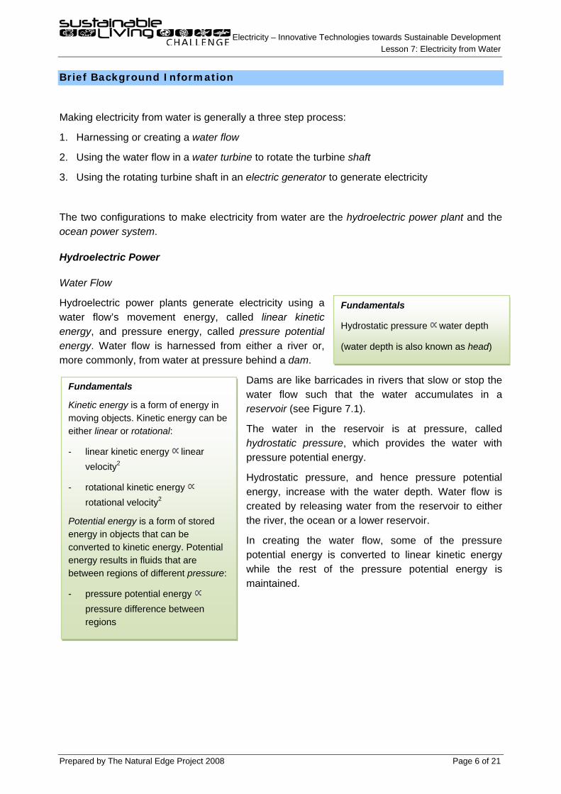
Making electricity from water is generally a three step process:
1. Harnessing or creating a water flow
2. Using the water flow in a water turbine to rotate the turbine shaft
3. Using the rotating turbine shaft in an electric generator to generate electricity
The two configurations to make electricity from water are the hydroelectric power plant and the ocean power system.
Hydroelectric Power
Water Flow
Hydroelectric power plants generate electricity using a water flow’s movement energy, called linear kinetic energy, and pressure energy, called pressure potential energy. Water flow is harnessed from either a river or, more commonly, from water at pressure behind a dam.
Dams are like barricades in rivers that slow or stop the water flow such that the water accumulates in a reservoir (see Figure 7.1).
The water in the reservoir is at pressure, called hydrostatic pressure, which provides the water with pressure potential energy.
Hydrostatic pressure, and hence pressure potential energy, increase with the water depth. Water flow is created by releasing water from the reservoir to either the river, the ocean or a lower reservoir.
In creating the water flow, some of the pressure potential energy is converted to linear kinetic energy while the rest of the pressure potential energy is maintained.
Fundamentals
Hydrostatic pressure water depth
(water depth is also known as head)
Fundamentals
Kinetic energy is a form of energy in moving objects. Kinetic energy can be either linear or rotational:
- linear kinetic energy linear velocity2
- rotational kinetic energy rotational velocity2
Potential energy is a form of stored energy in objects that can be converted to kinetic energy. Potential energy results in fluids that are between regions of different pressure:
- pressure potential energy pressure difference between regions
Electricity – Innovative Technologies towards Sustainable Development Lesson 7: Electricity from Water
Prepared by The Natural Edge Project 2008 Page 7 of 21
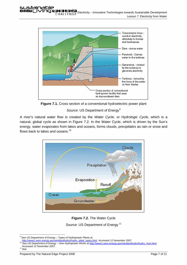
Figure 7.1. Cross section of a conventional hydroelectric power plant
Source: US Department of Energy9
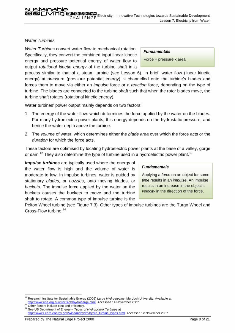
A river’s natural water flow is created by the Water Cycle, or Hydrologic Cycle, which is a natural, global cycle as shown in Figure 7.2. In the Water Cycle, which is driven by the Sun’s energy, water evaporates from lakes and oceans, forms clouds, precipitates as rain or snow and flows back to lakes and oceans.
10
Figure 7.2. The Water Cycle
Source: US Department of Energy 11
9 See US Department of Energy – Types of Hydropower Plants at
http://www1.eere.energy.gov/windandhydro/hydro_plant_types.html. Accessed 12 November 2007. 10 See US Department of Energy – How Hydropower Works at http://www1.eere.energy.gov/windandhydro/hydro_how.html.
Accessed 12 November 2007. 11 Ibid.
Electricity – Innovative Technologies towards Sustainable Development Lesson 7: Electricity from Water
Prepared by The Natural Edge Project 2008 Page 8 of 21
Water Turbines
Water Turbines convert water flow to mechanical rotation. Specifically, they convert the combined input linear kinetic energy and pressure potential energy of water flow to output rotational kinetic energy of the turbine shaft in a process similar to that of a steam turbine (see Lesson 6). In brief, water flow (linear kinetic energy) at pressure (pressure potential energy) is channelled onto the turbine’s blades and forces them to move via either an impulse force or a reaction force, depending on the type of turbine. The blades are connected to the turbine shaft such that when the rotor blades move, the turbine shaft rotates (rotational kinetic energy).
Water turbines’ power output mainly depends on two factors:
1. The energy of the water flow: which determines the force applied by the water on the blades. For many hydroelectric power plants, this energy depends on the hydrostatic pressure, and hence the water depth above the turbine.
2. The volume of water: which determines either the blade area over which the force acts or the duration for which the force acts.
These factors are optimised by locating hydroelectric power plants at the base of a valley, gorge or dam.12 They also determine the type of turbine used in a hydroelectric power plant.13
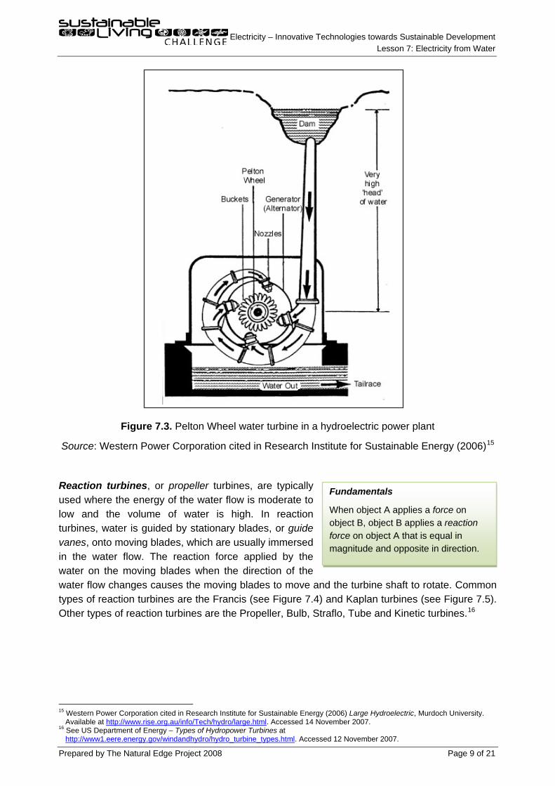
Impulse turbines are typically used where the energy of the water flow is high and the volume of water is moderate to low. In impulse turbines, water is guided by stationary blades, or nozzles, onto moving blades, or buckets. The impulse force applied by the water on the buckets causes the buckets to move and the turbine shaft to rotate. A common type of impulse turbine is the Pelton Wheel turbine (see Figure 7.3). Other types of impulse turbines are the Turgo Wheel and Cross-Flow turbine.
14
12 Research Institute for Sustainable Energy (2006) Large Hydroelectric, Murdoch University. Available at
http://www.rise.org.au/info/Tech/hydro/large.html. Accessed 14 November 2007. 13 Other factors include cost and efficiency. 14 See US Department of Energy – Types of Hydropower Turbines at
http://www1.eere.energy.gov/windandhydro/hydro_turbine_types.html. Accessed 12 November 2007.
Fundamentals
Applying a force on an object for some time results in an impulse. An impulse results in an increase in the object’s velocity in the direction of the force.
Fundamentals
Force = pressure x area
Electricity – Innovative Technologies towards Sustainable Development Lesson 7: Electricity from Water
Prepared by The Natural Edge Project 2008 Page 9 of 21
Figure 7.3. Pelton Wheel water turbine in a hydroelectric power plant
Source: Western Power Corporation cited in Research Institute for Sustainable Energy (2006)15
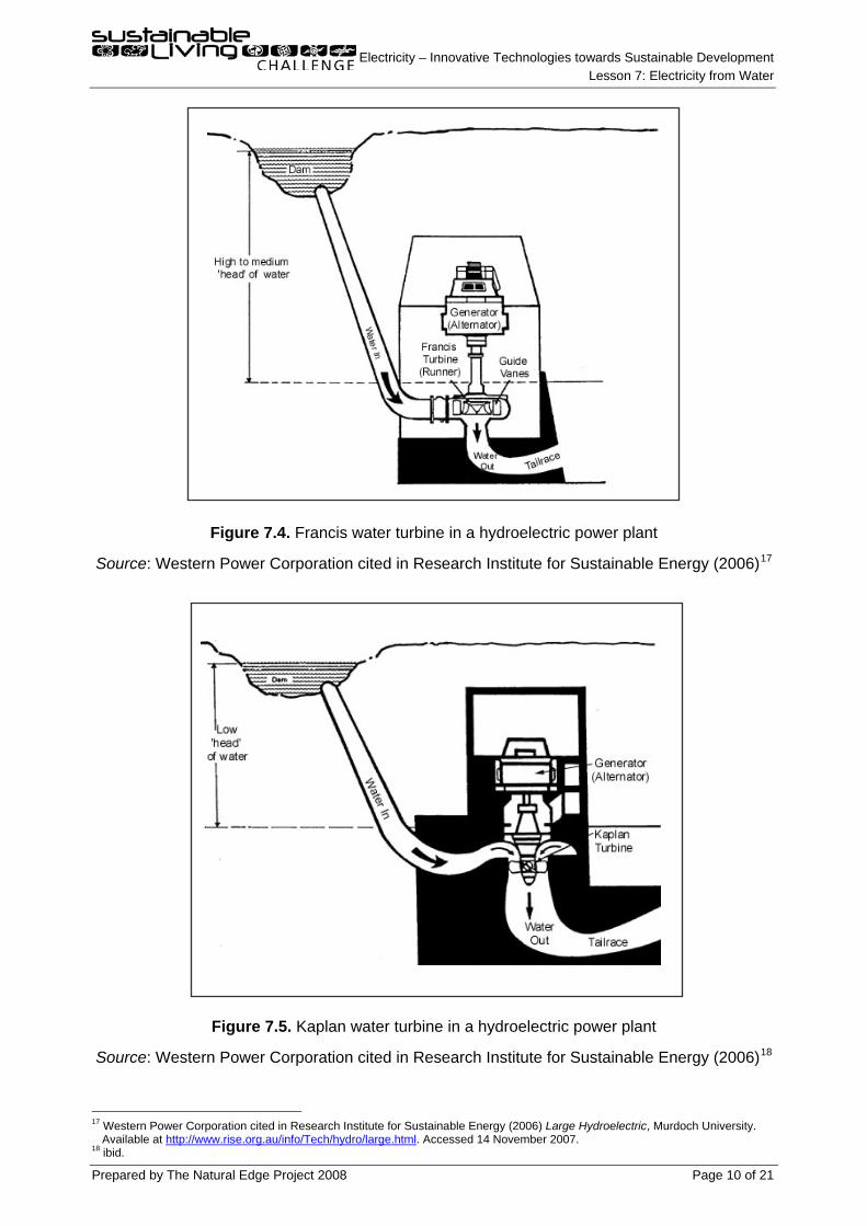
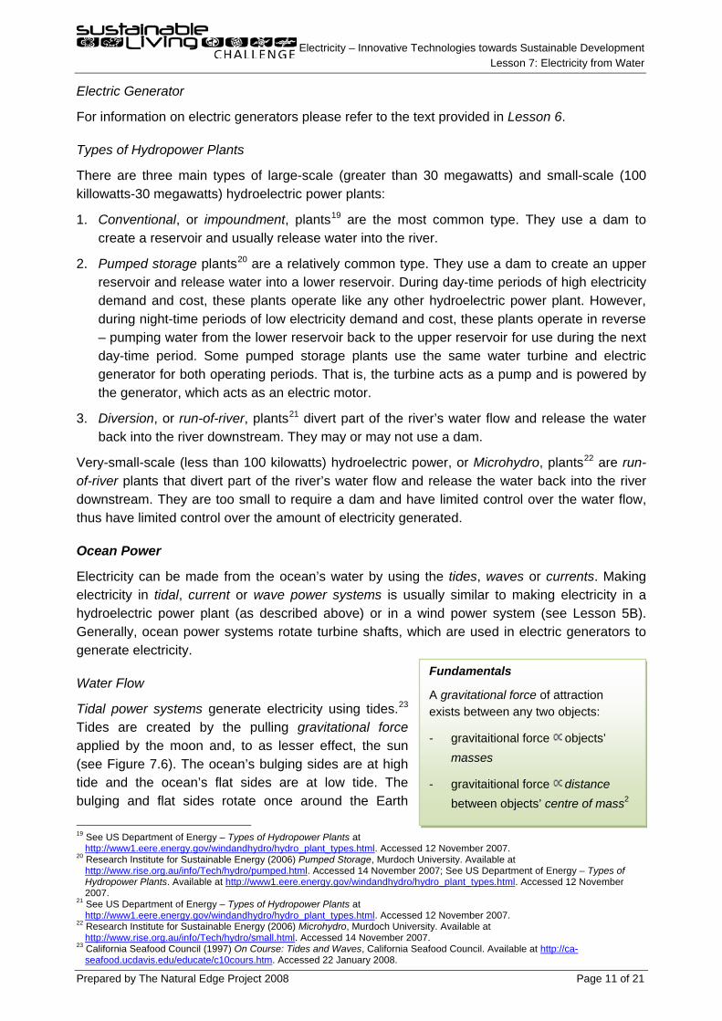
Reaction turbines, or propeller turbines, are typically used where the energy of the water flow is moderate to low and the volume of water is high. In reaction turbines, water is guided by stationary blades, or guide vanes, onto moving blades, which are usually immersed in the water flow. The reaction force applied by the water on the moving blades when the direction of the water flow changes causes the moving blades to move and the turbine shaft to rotate. Common types of reaction turbines are the Francis (see Figure 7.4) and Kaplan turbines (see Figure 7.5). Other types of reaction turbines are the Propeller, Bulb, Straflo, Tube and Kinetic turbines.
16
15 Western Power Corporation cited in Research Institute for Sustainable Energy (2006) Large Hydroelectric, Murdoch University.
Available at
http://www.rise.org.au/info/Tech/hydro/large.html. Accessed 14 November 2007. 16 See US Department of Energy – Types of Hydropower Turbines at
http://www1.eere.energy.gov/windandhydro/hydro_turbine_types.html. Accessed 12 November 2007.
Fundamentals
When object A applies a force on object B, object B applies a reaction force on object A that is equal in magnitude and opposite in direction.
Electricity – Innovative Technologies towards Sustainable Development Lesson 7: Electricity from Water
Prepared by The Natural Edge Project 2008 Page 10 of 21
Figure 7.4. Francis water turbine in a hydroelectric power plant
Source: Western Power Corporation cited in Research Institute for Sustainable Energy (2006)17
Figure 7.5. Kaplan water turbine in a hydroelectric power plant
Source: Western Power Corporation cited in Research Institute for Sustainable Energy (2006)18
17 Western Power Corporation cited in Research Institute for Sustainable Energy (2006) Large Hydroelectric, Murdoch University.
Available at
http://www.rise.org.au/info/Tech/hydro/large.html. Accessed 14 November 2007. 18 ibid.
Electricity – Innovative Technologies towards Sustainable Development Lesson 7: Electricity from Water
Prepared by The Natural Edge Project 2008 Page 11 of 21
Electric Generator
For information on electric generators please refer to the text provided in Lesson 6.
Types of Hydropower Plants
There are three main types of large-scale (greater than 30 megawatts) and small-scale (100 killowatts-30 megawatts) hydroelectric power plants:
1. Conventional, or impoundment, plants19
2. Pumped storage plants
are the most common type. They use a dam to create a reservoir and usually release water into the river.
20
3. Diversion, or run-of-river, plants
are a relatively common type. They use a dam to create an upper reservoir and release water into a lower reservoir. During day-time periods of high electricity demand and cost, these plants operate like any other hydroelectric power plant. However, during night-time periods of low electricity demand and cost, these plants operate in reverse – pumping water from the lower reservoir back to the upper reservoir for use during the next day-time period. Some pumped storage plants use the same water turbine and electric generator for both operating periods. That is, the turbine acts as a pump and is powered by the generator, which acts as an electric motor.
21
Very-small-scale (less than 100 kilowatts) hydroelectric power, or Microhydro, plants
divert part of the river’s water flow and release the water back into the river downstream. They may or may not use a dam.
22
Electricity can be made from the ocean’s water by using the tides, waves or currents. Making electricity in tidal, current or wave power systems is usually similar to making electricity in a hydroelectric power plant (as described above) or in a wind power system (see Lesson 5B). Generally, ocean power systems rotate turbine shafts, which are used in electric generators to generate electricity.
are run-of-river plants that divert part of the river’s water flow and release the water back into the river downstream. They are too small to require a dam and have limited control over the water flow, thus have limited control over the amount of electricity generated.
Ocean Power
Water Flow
Tidal power systems generate electricity using tides.23
19 See US Department of Energy – Types of Hydropower Plants at
Tides are created by the pulling gravitational force applied by the moon and, to as lesser effect, the sun (see Figure 7.6). The ocean’s bulging sides are at high tide and the ocean’s flat sides are at low tide. The bulging and flat sides rotate once around the Earth
http://www1.eere.energy.gov/windandhydro/hydro_plant_types.html. Accessed 12 November 2007. 20 Research Institute for Sustainable Energy (2006) Pumped Storage, Murdoch University. Available at
http://www.rise.org.au/info/Tech/hydro/pumped.html. Accessed 14 November 2007; See US Department of Energy – Types of Hydropower Plants. Available at http://www1.eere.energy.gov/windandhydro/hydro_plant_types.html. Accessed 12 November 2007.
21 See US Department of Energy – Types of Hydropower Plants at http://www1.eere.energy.gov/windandhydro/hydro_plant_types.html. Accessed 12 November 2007.
22 Research Institute for Sustainable Energy (2006) Microhydro, Murdoch University. Available at http://www.rise.org.au/info/Tech/hydro/small.html. Accessed 14 November 2007.
23 California Seafood Council (1997) On Course: Tides and Waves, California Seafood Council. Available at http://ca-seafood.ucdavis.edu/educate/c10cours.htm. Accessed 22 January 2008.
Fundamentals
A gravitational force of attraction exists between any two objects:
- gravitaitional force objects’ masses
- gravitaitional force distance between objects’ centre of mass2
Electricity – Innovative Technologies towards Sustainable Development Lesson 7: Electricity from Water
Prepared by The Natural Edge Project 2008 Page 12 of 21
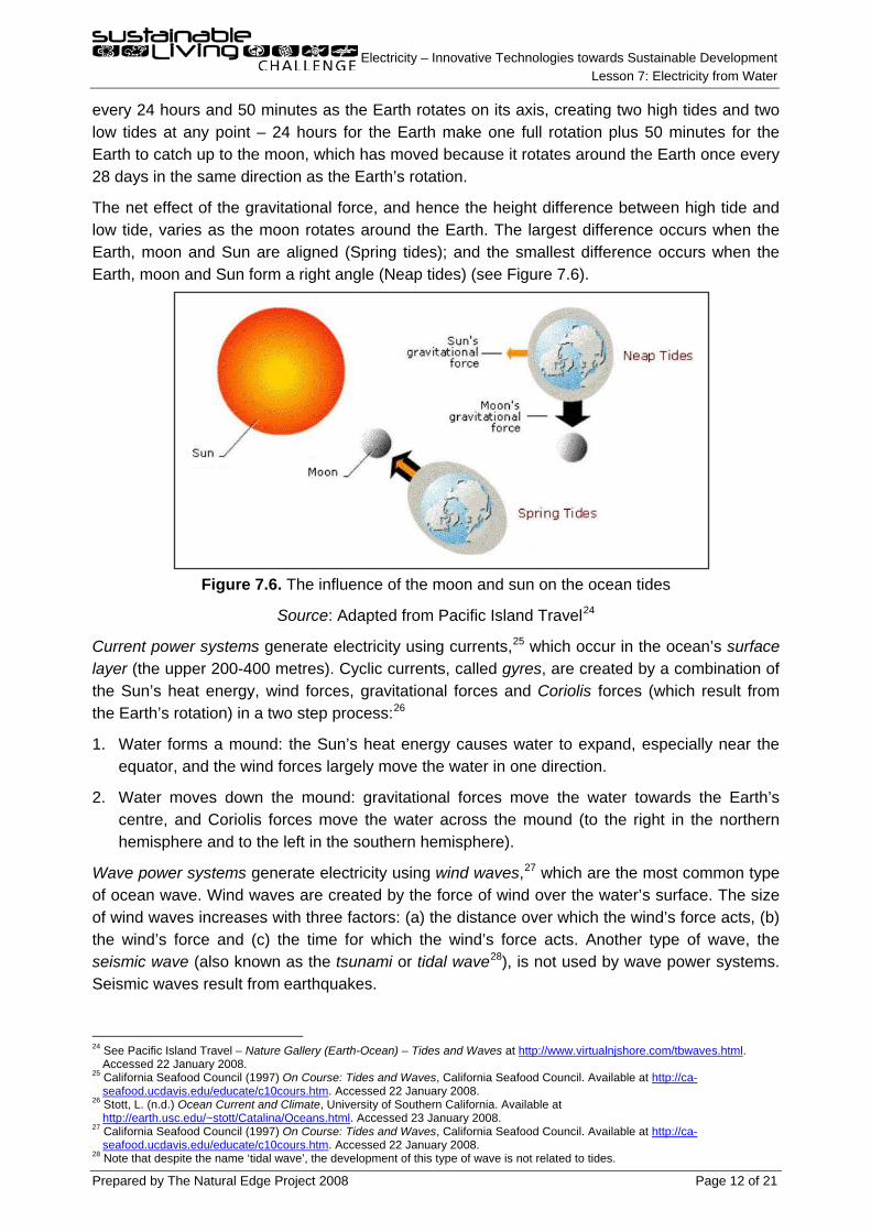
every 24 hours and 50 minutes as the Earth rotates on its axis, creating two high tides and two low tides at any point – 24 hours for the Earth make one full rotation plus 50 minutes for the Earth to catch up to the moon, which has moved because it rotates around the Earth once every 28 days in the same direction as the Earth’s rotation.
The net effect of the gravitational force, and hence the height difference between high tide and low tide, varies as the moon rotates around the Earth. The largest difference occurs when the Earth, moon and Sun are aligned (Spring tides); and the smallest difference occurs when the Earth, moon and Sun form a right angle (Neap tides) (see Figure 7.6).
Figure 7.6. The influence of the moon and sun on the ocean tides
Source: Adapted from Pacific Island Travel24
Current power systems generate electricity using currents,
25 which occur in the ocean’s surface
layer (the upper 200-400 metres). Cyclic currents, called gyres, are created by a combination of the Sun’s heat energy, wind forces, gravitational forces and Coriolis forces (which result from the Earth’s rotation) in a two step process:26
1. Water forms a mound: the Sun’s heat energy causes water to expand, especially near the equator, and the wind forces largely move the water in one direction.
2. Water moves down the mound: gravitational forces move the water towards the Earth’s centre, and Coriolis forces move the water across the mound (to the right in the northern hemisphere and to the left in the southern hemisphere).
Wave power systems generate electricity using wind waves,27 which are the most common type of ocean wave. Wind waves are created by the force of wind over the water’s surface. The size of wind waves increases with three factors: (a) the distance over which the wind’s force acts, (b) the wind’s force and (c) the time for which the wind’s force acts. Another type of wave, the seismic wave (also known as the tsunami or tidal wave28
24 See Pacific Island Travel – Nature Gallery (Earth-Ocean) – Tides and Waves at
), is not used by wave power systems. Seismic waves result from earthquakes.
http://www.virtualnjshore.com/tbwaves.html. Accessed 22 January 2008.
25 California Seafood Council (1997) On Course: Tides and Waves, California Seafood Council. Available at http://ca-seafood.ucdavis.edu/educate/c10cours.htm. Accessed 22 January 2008.
26 Stott, L. (n.d.) Ocean Current and Climate, University of Southern California. Available at http://earth.usc.edu/~stott/Catalina/Oceans.html. Accessed 23 January 2008.
27 California Seafood Council (1997) On Course: Tides and Waves, California Seafood Council. Available at http://ca-seafood.ucdavis.edu/educate/c10cours.htm. Accessed 22 January 2008.
28 Note that despite the name ‘tidal wave’, the development of this type of wave is not related to tides.
Electricity – Innovative Technologies towards Sustainable Development Lesson 7: Electricity from Water
Prepared by The Natural Edge Project 2008 Page 13 of 21
Tidal Power Systems29
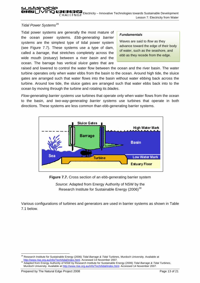
Tidal power systems are generally the most mature of the ocean power systems. Ebb-generating barrier systems are the simplest type of tidal power system (see Figure 7.7). These systems use a type of dam, called a barrage, that stretches completely across the wide mouth (estuary) between a river basin and the ocean. The barrage has vertical sluice gates that are raised and lowered to control the water flow between the ocean and the river basin. The water turbine operates only when water ebbs from the basin to the ocean. Around high tide, the sluice gates are arranged such that water flows into the basin without water ebbing back across the turbine. Around low tide, the sluice gates are arranged such that water ebbs back into to the ocean by moving through the turbine and rotating its blades.
Flow-generating barrier systems use turbines that operate only when water flows from the ocean to the basin, and two-way-generating barrier systems use turbines that operate in both directions. These systems are less common than ebb-generating barrier systems.
Figure 7.7. Cross section of an ebb-generating barrier system
Source: Adapted from Energy Authority of NSW by the Research Institute for Sustainable Energy (2006)30
29 Research Institute for Sustainable Energy (2006) Tidal Barrage & Tidal Turbines, Murdoch University. Available at
Various configurations of turbines and generators are used in barrier systems as shown in Table 7.1 below.
http://www.rise.org.au/info/Tech/tidal/index.html. Accessed 14 November 2007. 30 Adapted from Energy Authority of NSW by Research Institute for Sustainable Energy (2006) Tidal Barrage & Tidal Turbines,
Murdoch University. Available at http://www.rise.org.au/info/Tech/tidal/index.html. Accessed 14 November 2007.
Fundamentals
Waves are said to flow as they advance toward the edge of their body of water, such as the seashore, and ebb as they recede from the edge.
Electricity – Innovative Technologies towards Sustainable Development Lesson 7: Electricity from Water
Prepared by The Natural Edge Project 2008 Page 14 of 21
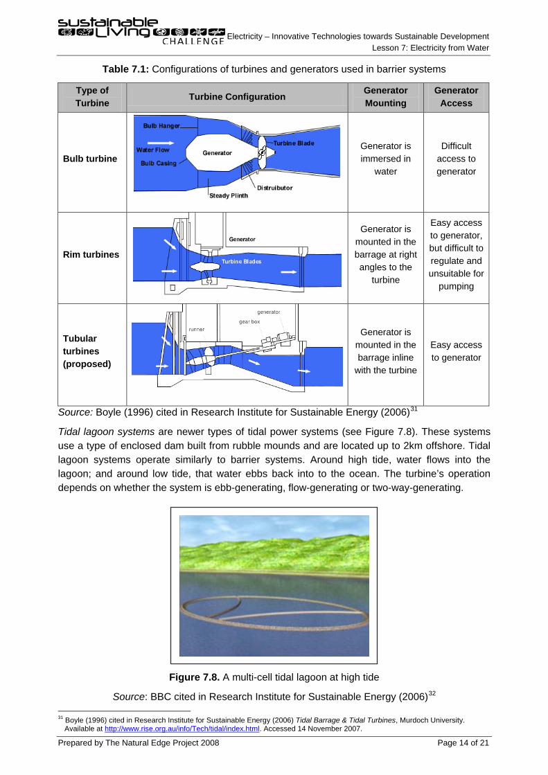
Table 7.1: Configurations of turbines and generators used in barrier systems
Type of Turbine
Turbine Configuration Generator Mounting
Generator Access
Bulb turbine
Generator is immersed in
water
Difficult access to generator
Rim turbines
Generator is mounted in the barrage at right angles to the
turbine
Easy access to generator, but difficult to regulate and unsuitable for
pumping
Tubular turbines (proposed)
Generator is mounted in the barrage inline
with the turbine
Easy access to generator
Source: Boyle (1996) cited in Research Institute for Sustainable Energy (2006)31
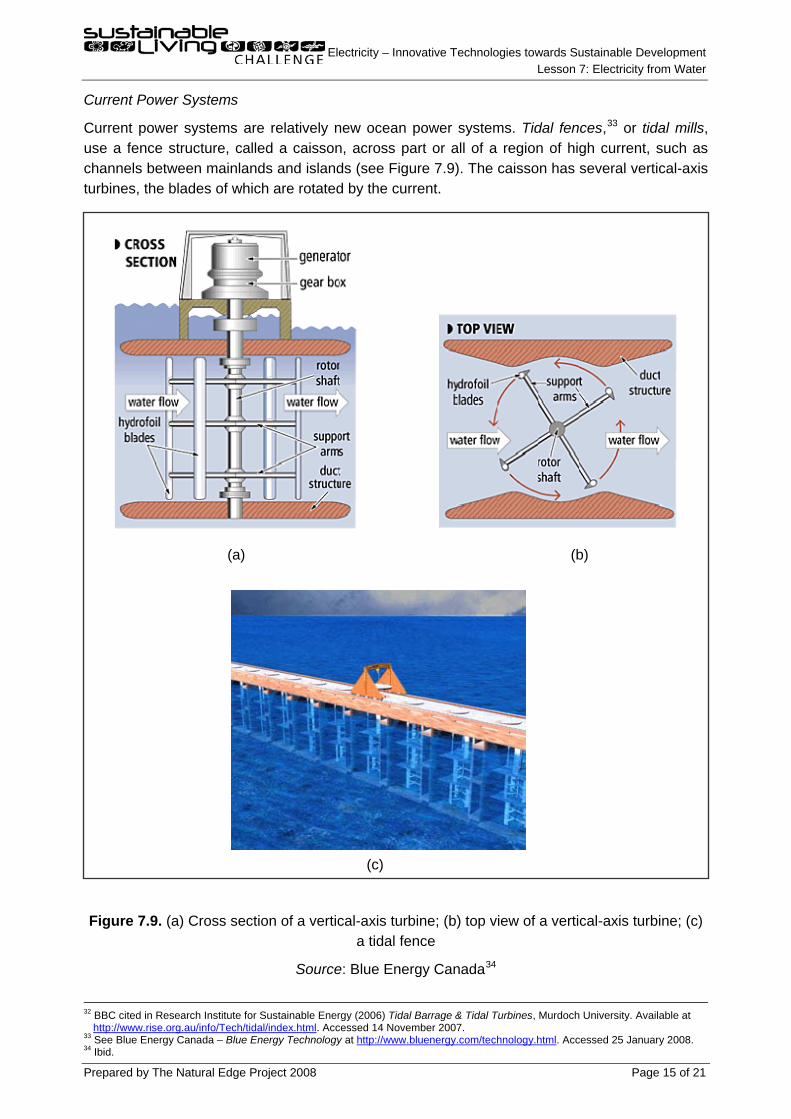
Tidal lagoon systems are newer types of tidal power systems (see Figure 7.8). These systems use a type of enclosed dam built from rubble mounds and are located up to 2km offshore. Tidal lagoon systems operate similarly to barrier systems. Around high tide, water flows into the lagoon; and around low tide, that water ebbs back into to the ocean. The turbine’s operation depends on whether the system is ebb-generating, flow-generating or two-way-generating.
Figure 7.8. A multi-cell tidal lagoon at high tide
Source: BBC cited in Research Institute for Sustainable Energy (2006)32
31 Boyle (1996) cited in Research Institute for Sustainable Energy (2006) Tidal Barrage & Tidal Turbines, Murdoch University.
Available at
http://www.rise.org.au/info/Tech/tidal/index.html. Accessed 14 November 2007.
Electricity – Innovative Technologies towards Sustainable Development Lesson 7: Electricity from Water
Prepared by The Natural Edge Project 2008 Page 15 of 21
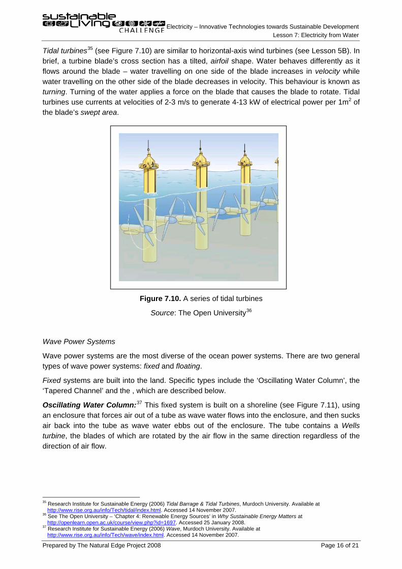
Current Power Systems
Current power systems are relatively new ocean power systems. Tidal fences,33
(a) (b)
(c)
Figure 7.9. (a) Cross section of a vertical-axis turbine; (b) top view of a vertical-axis turbine; (c) a tidal fence
or tidal mills, use a fence structure, called a caisson, across part or all of a region of high current, such as channels between mainlands and islands (see Figure 7.9). The caisson has several vertical-axis turbines, the blades of which are rotated by the current.
Source: Blue Energy Canada34
32 BBC cited in Research Institute for Sustainable Energy (2006) Tidal Barrage & Tidal Turbines, Murdoch University. Available at
http://www.rise.org.au/info/Tech/tidal/index.html. Accessed 14 November 2007. 33 See Blue Energy Canada – Blue Energy Technology at http://www.bluenergy.com/technology.html. Accessed 25 January 2008. 34 Ibid.
Electricity – Innovative Technologies towards Sustainable Development Lesson 7: Electricity from Water
Prepared by The Natural Edge Project 2008 Page 16 of 21
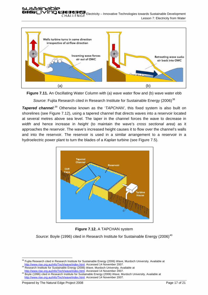
Tidal turbines35
Figure 7.10. A series of tidal turbines
(see Figure 7.10) are similar to horizontal-axis wind turbines (see Lesson 5B). In brief, a turbine blade’s cross section has a tilted, airfoil shape. Water behaves differently as it flows around the blade – water travelling on one side of the blade increases in velocity while water travelling on the other side of the blade decreases in velocity. This behaviour is known as turning. Turning of the water applies a force on the blade that causes the blade to rotate. Tidal turbines use currents at velocities of 2-3 m/s to generate 4-13 kW of electrical power per 1m2 of the blade’s swept area.
Source: The Open University36
Oscillating Water Column:
Wave Power Systems
Wave power systems are the most diverse of the ocean power systems. There are two general types of wave power systems: fixed and floating.
Fixed systems are built into the land. Specific types include the ‘Oscillating Water Column’, the ‘Tapered Channel’ and the , which are described below.
37
35 Research Institute for Sustainable Energy (2006) Tidal Barrage & Tidal Turbines, Murdoch University. Available at
This fixed system is built on a shoreline (see Figure 7.11), using an enclosure that forces air out of a tube as wave water flows into the enclosure, and then sucks air back into the tube as wave water ebbs out of the enclosure. The tube contains a Wells turbine, the blades of which are rotated by the air flow in the same direction regardless of the direction of air flow.
http://www.rise.org.au/info/Tech/tidal/index.html. Accessed 14 November 2007. 36 See The Open University – ‘Chapter 4: Renewable Energy Sources’ in Why Sustainable Energy Matters at
http://openlearn.open.ac.uk/course/view.php?id=1697. Accessed 25 January 2008. 37 Research Institute for Sustainable Energy (2006) Wave, Murdoch University. Available at
http://www.rise.org.au/info/Tech/wave/index.html. Accessed 14 November 2007.
Electricity – Innovative Technologies towards Sustainable Development Lesson 7: Electricity from Water
Prepared by The Natural Edge Project 2008 Page 17 of 21
(a) (b)
Figure 7.11. An Oscillating Water Column with (a) wave water flow and (b) wave water ebb
Source: Fujita Research cited in Research Institute for Sustainable Energy (2006)38
Tapered channel:
39
Figure 7.12. A TAPCHAN system
Otherwise known as the ‘TAPCHAN’, this fixed system is also built on shorelines (see Figure 7.12), using a tapered channel that directs waves into a reservoir located at several metres above sea level. The taper in the channel forces the wave to decrease in width and hence increase in height (to maintain the wave’s cross sectional area) as it approaches the reservoir. The wave’s increased height causes it to flow over the channel’s walls and into the reservoir. The reservoir is used in a similar arrangement to a reservoir in a hydroelectric power plant to turn the blades of a Kaplan turbine (see Figure 7.5).
Source: Boyle (1996) cited in Research Institute for Sustainable Energy (2006)40
38 Fujita Research cited in Research Institute for Sustainable Energy (2006) Wave, Murdoch University. Available at
http://www.rise.org.au/info/Tech/wave/index.html. Accessed 14 November 2007. 39 Research Institute for Sustainable Energy (2006) Wave, Murdoch University. Available at
http://www.rise.org.au/info/Tech/wave/index.html. Accessed 14 November 2007. 40 Boyle (1996) cited in Research Institute for Sustainable Energy (2006) Wave, Murdoch University. Available at
http://www.rise.org.au/info/Tech/wave/index.html. Accessed 14 November 2007.

Electricity – Innovative Technologies towards Sustainable Development Lesson 7: Electricity from Water
Prepared by The Natural Edge Project 2008 Page 18 of 21
WaveRoller:41
(a) (b)
Figure 7.13. (a) A WaveRoller plate and piston pump; (b) A WaveRoller system
This fixed system is built on shallow seabeds (see Figure 7.13), using plates that are hinged to the seabed. The plates partially rotate in both directions by force of the water flow and ebb of bottom waves. The plate’s partial rotation is converted into full shaft rotation by a piston pump.
Source: AW-Energy Oy42
Pelamis Wave Energy Converter:
Floating systems float in the ocean. Specific types include the ‘Pelamis Wave Energy Converter’, the ‘Salter Duck’, ‘Wave Dragon’
43
Figure 7.14. A Pelamis Wave Energy Converter
This floating system uses a series of hinged cylinders, with each hinge coupled to a hydraulic ram (a tube that contains oil that can be forced in and out) and a hydraulic motor (see Figure 7.14). The cylinders’ height varies with the wave’s height, and the hinges partially rotate accordingly. Each hinge’s partial rotation forces oil through a ram and into a hydraulic motor. The oil flow through the motor then causes the motor’s shaft to fully rotate.
Source: Pelamis Wave Power44
41 See AW-Energy Oy – WaveRoller. Available at
http://www.aw-energy.com/page_1_2.html. Accessed 25 January 2008. 42 See AW-Energy Oy – WaveRoller at http://www.aw-energy.com/page_1_2.html. Accessed 25 January 2008. 43 See Pelamis Wave Power – The Pelamis Wave Energy Converter at http://www.pelamiswave.com/content.php?id=161. Accessed
25 January 2008. 44 Ibid.
Electricity – Innovative Technologies towards Sustainable Development Lesson 7: Electricity from Water
Prepared by The Natural Edge Project 2008 Page 19 of 21
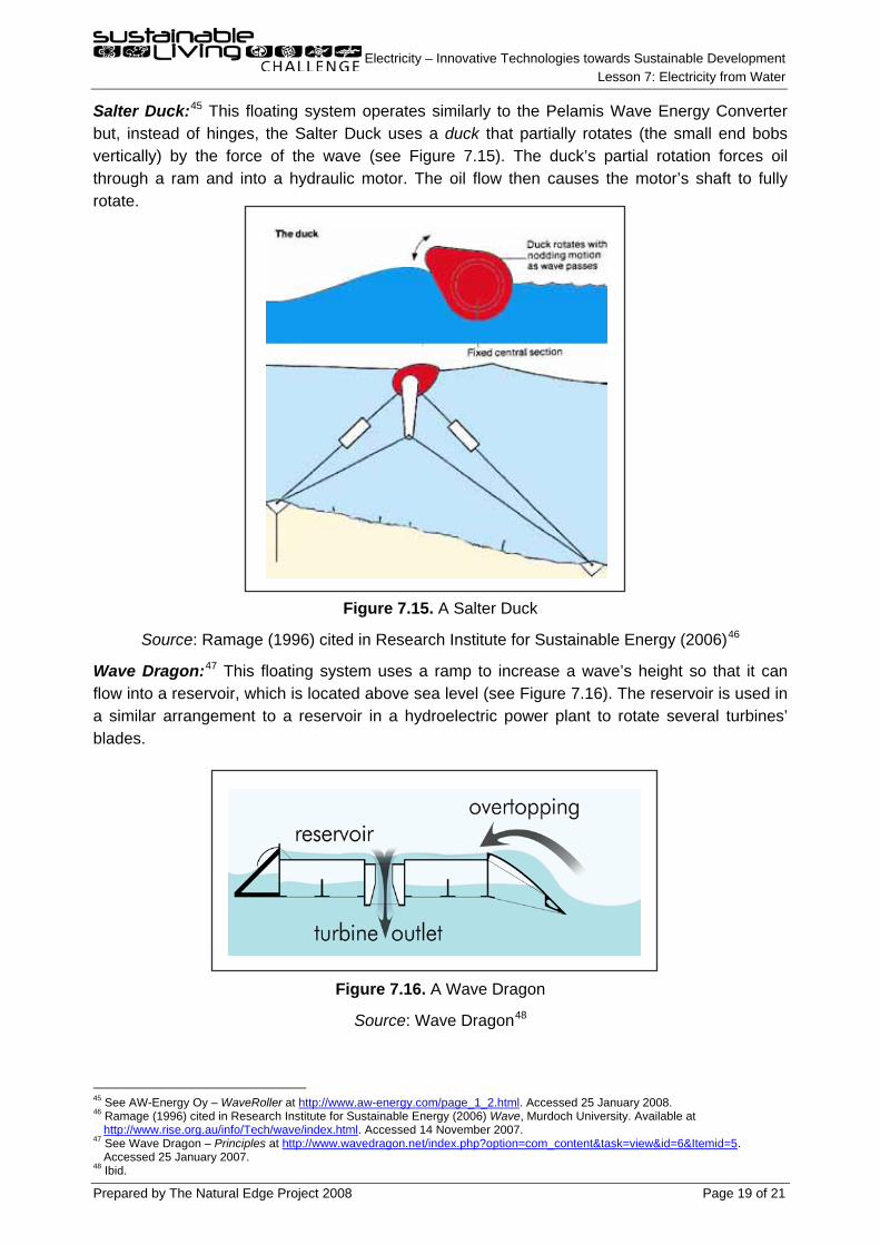
Salter Duck:45
Source: Ramage (1996) cited in Research Institute for Sustainable Energy (2006)
This floating system operates similarly to the Pelamis Wave Energy Converter but, instead of hinges, the Salter Duck uses a duck that partially rotates (the small end bobs vertically) by the force of the wave (see Figure 7.15). The duck’s partial rotation forces oil through a ram and into a hydraulic motor. The oil flow then causes the motor’s shaft to fully rotate.
Figure 7.15. A Salter Duck 46
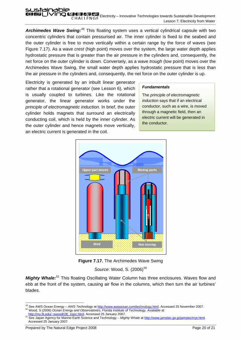
Wave Dragon:
47
Figure 7.16. A Wave Dragon
This floating system uses a ramp to increase a wave’s height so that it can flow into a reservoir, which is located above sea level (see Figure 7.16). The reservoir is used in a similar arrangement to a reservoir in a hydroelectric power plant to rotate several turbines’ blades.
Source: Wave Dragon48
45 See AW-Energy Oy – WaveRoller at
http://www.aw-energy.com/page_1_2.html. Accessed 25 January 2008. 46 Ramage (1996) cited in Research Institute for Sustainable Energy (2006) Wave, Murdoch University. Available at
http://www.rise.org.au/info/Tech/wave/index.html. Accessed 14 November 2007. 47 See Wave Dragon – Principles at http://www.wavedragon.net/index.php?option=com_content&task=view&id=6&Itemid=5.
Accessed 25 January 2007. 48 Ibid.
Electricity – Innovative Technologies towards Sustainable Development Lesson 7: Electricity from Water
Prepared by The Natural Edge Project 2008 Page 20 of 21
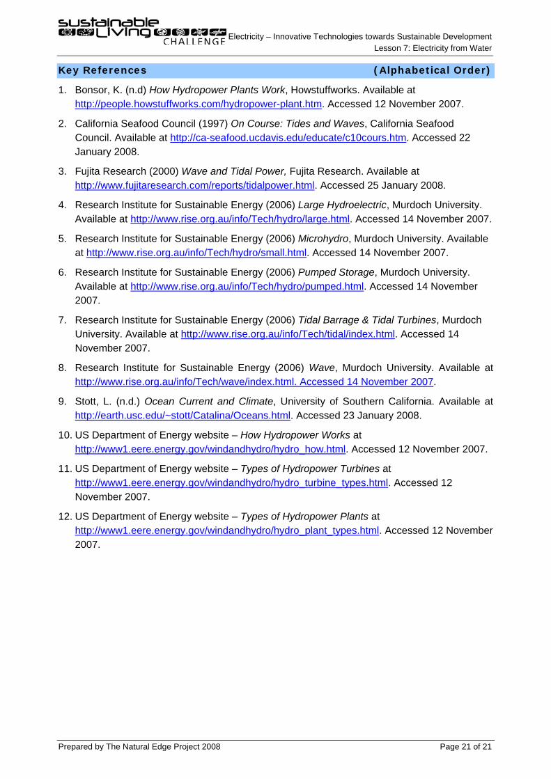
Archimedes Wave Swing:49
Electricity is generated by an inbuilt linear generator rather that a rotational generator (see Lesson 6), which is usually coupled to turbines. Like the rotational generator, the linear generator works under the principle of electromagnetic induction. In brief, the outer cylinder holds magnets that surround an electrically conducting coil, which is held by the inner cylinder. As the outer cylinder and hence magnets move vertically, an electric current is generated in the coil.
This floating system uses a vertical cylindrical capsule with two concentric cylinders that contain pressurised air. The inner cylinder is fixed to the seabed and the outer cylinder is free to move vertically within a certain range by the force of waves (see Figure 7.17). As a wave crest (high point) moves over the system, the large water depth applies hydrostatic pressure that is greater than the air pressure in the cylinders and, consequently, the net force on the outer cylinder is down. Conversely, as a wave trough (low point) moves over the Archimedes Wave Swing, the small water depth applies hydrostatic pressure that is less than the air pressure in the cylinders and, consequently, the net force on the outer cylinder is up.
Figure 7.17. The Archimedes Wave Swing
Source: Wood, S. (2006)50
Mighty Whale:
51
49 See AWS Ocean Energy – AWS Technology at
This floating Oscillating Water Column has three enclosures. Waves flow and ebb at the front of the system, causing air flow in the columns, which then turn the air turbines’ blades.
http://www.awsocean.com/technology.html. Accessed 25 November 2007. 50 Wood, S (2006) Ocean Energy and Observatories, Florida Institute of Technology. Available at
http://my.fit.edu/~swood/OE_topic.html. Accessed 25 January 2007. 51 See Japan Agency for Marine-Earth Science and Technology – Mighty Whale at http://www.jamstec.go.jp/jamstec/myt.html.
Accessed 25 January 2007.
Fundamentals
The principle of electromagnetic induction says that if an electrical conductor, such as a wire, is moved through a magnetic field, then an electric current will be generated in the conductor.
Electricity – Innovative Technologies towards Sustainable Development Lesson 7: Electricity from Water
Prepared by The Natural Edge Project 2008 Page 21 of 21
Key References (Alphabetical Order)
1. Bonsor, K. (n.d) How Hydropower Plants Work, Howstuffworks. Available at http://people.howstuffworks.com/hydropower-plant.htm. Accessed 12 November 2007.
2. California Seafood Council (1997) On Course: Tides and Waves, California Seafood Council. Available at http://ca-seafood.ucdavis.edu/educate/c10cours.htm. Accessed 22 January 2008.
3. Fujita Research (2000) Wave and Tidal Power, Fujita Research. Available at http://www.fujitaresearch.com/reports/tidalpower.html. Accessed 25 January 2008.
4. Research Institute for Sustainable Energy (2006) Large Hydroelectric, Murdoch University. Available at http://www.rise.org.au/info/Tech/hydro/large.html. Accessed 14 November 2007.
5. Research Institute for Sustainable Energy (2006) Microhydro, Murdoch University. Available at http://www.rise.org.au/info/Tech/hydro/small.html. Accessed 14 November 2007.
6. Research Institute for Sustainable Energy (2006) Pumped Storage, Murdoch University. Available at http://www.rise.org.au/info/Tech/hydro/pumped.html. Accessed 14 November 2007.
7. Research Institute for Sustainable Energy (2006) Tidal Barrage & Tidal Turbines, Murdoch University. Available at http://www.rise.org.au/info/Tech/tidal/index.html. Accessed 14 November 2007.
8. Research Institute for Sustainable Energy (2006) Wave, Murdoch University. Available at http://www.rise.org.au/info/Tech/wave/index.html. Accessed 14 November 2007.
9. Stott, L. (n.d.) Ocean Current and Climate, University of Southern California. Available at http://earth.usc.edu/~stott/Cata . Accessed 23 January 2008. lina/Oceans.html
10. US Department of Energy website – How Hydropower Works at http://www1.eere.energy.gov/windandhydro/hydro_how.html. Accessed 12 November 2007.
11. US Department of Energy website – Types of Hydropower Turbines at http://www1.eere.energy.gov/windandhydro/hydro_turbine_types.html. Accessed 12 November 2007.
12. US Department of Energy website – Types of Hydropower Plants at http://www1.eere.energy.gov/windandhydro/hydro_plant_types.html. Accessed 12 November 2007.