electrics for rolling stock - schaltbau · catalogue f290 :: footrests, dsd push buttons and dsd...
TRANSCRIPT
4
More information here: schaltbau-gmbh.com
Catalogue F290 :: Footrests, DSD push buttons and DSD foot switches for rail vehicles
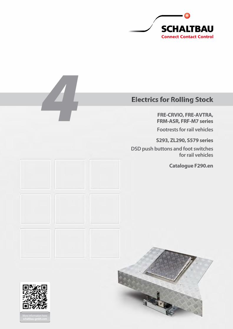
Electrics for Rolling Stock
FRE-CRVIO, FRE-AVTRA, FRM-ASR, FRF-M7 series Footrests for rail vehicles
S293, ZL290, S579 series DSD push buttons and foot switches
for rail vehicles
Catalogue F290.en
2
Subject to change
Footrests, DSD push buttons and DSD foot switches
Design to order
● Complete in-house customized design and manufacture ● Integrated DSD foot switch, additional foot switchs on request ● Reliable, rugged, maintenance-free ● Standard-compliant design and components
Based on many years' experience, we develop new footrests in close cooperation with the customer adependent on their require-ments and exact specifications. The footrests are then manufactured by Schaltbau in their own works. Schaltbau assists the customer with the specifications and supplies complete documentation.
Our Portfolio
Rail vehicles in good hands – with footrests, DSD foot switches and DSD push buttons
assembly in our factory is DIN EN ISO 9001 and IRIS (Interna tional Railway Industry Standard) compliant. The long term pay-off is the long term in low follow-up costs for service and maintenance and, of course, a high degree of safety over the vehicle‘s many years of operation. The design of our robust, shockproof and vibration-proof footrests enables a great variety of possible variants.
Footrests with DSD switches allow the driver to operate the driver safety device from an ergonomic seating position while keeping hands free. Addi-tional functions, e.g. for track sanding or horn activation can be integrated. An optional heatable base plate provides additional comfort in winter. Footrests and DSD switches can be found in railway vehicles all around the world. They operate with the utmost safety, reliability, longevity and low maintenance. The quality system for development, manufacturing and
Globally leading
Customized solutions
In cooperation with you, our experienced design engineers select appropriate solutions from the existing basic models and customize them to meet your needs.
Generally, footrests are customized product developments because of the need for adaptations.
Together, we find the optimum, state-of-the-art solution for every require-ment. Our inhouse electronics development division enables us to respond quickly and flexibly to changing needs. Comprehensive type testing is performed in our laboratory according to customer specifications.
Modern project management ensures adherence to the required dead-lines and quality – even when requirements change. Talk to us and set us a challenge.
3
Subject to change
Footrests DSD switches
Series overview
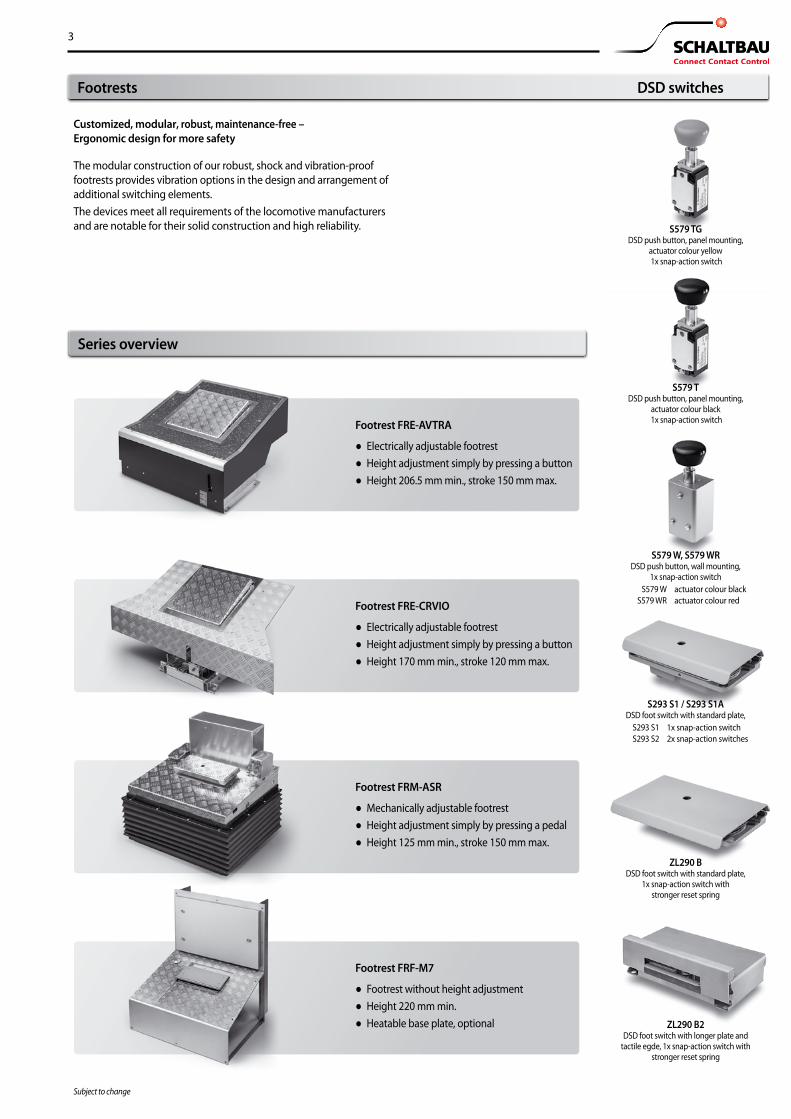
Customized, modular, robust, maintenance-free – Ergonomic design for more safety
The modular construction of our robust, shock and vibration-proof footrests provides vibration options in the design and arrangement of additional switching elements. The devices meet all requirements of the locomotive manufacturers and are notable for their solid construction and high reliability. S579 TG
DSD push button, panel mounting, actuator colour yellow 1x snap-action switch
S579 T DSD push button, panel mounting,
actuator colour black 1x snap-action switch
S293 S1 / S293 S1A DSD foot switch with standard plate,
S293 S1 1x snap-action switchS293 S2 2x snap-action switches
ZL290 B DSD foot switch with standard plate,
1x snap-action switch with stronger reset spring
ZL290 B2 DSD foot switch with longer plate and
tactile egde, 1x snap-action switch with stronger reset spring
Footrest FRE-AVTRA
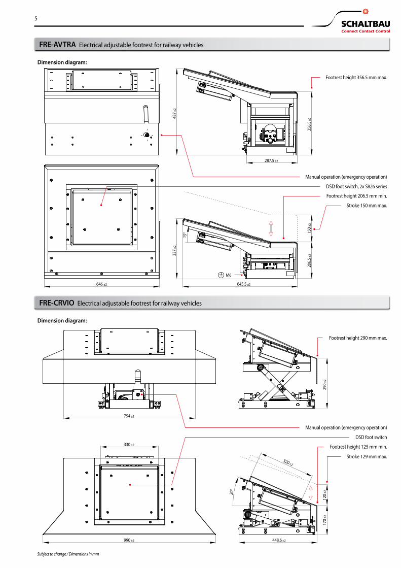
● Electrically adjustable footrest ● Height adjustment simply by pressing a button ● Height 206.5 mm min., stroke 150 mm max.
Footrest FRM-ASR
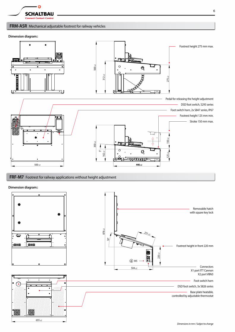
● Mechanically adjustable footrest ● Height adjustment simply by pressing a pedal ● Height 125 mm min., stroke 150 mm max.
Footrest FRE-CRVIO
● Electrically adjustable footrest ● Height adjustment simply by pressing a button ● Height 170 mm min., stroke 120 mm max.
Footrest FRF-M7
● Footrest without height adjustment ● Height 220 mm min. ● Heatable base plate, optional
S579 W, S579 WR DSD push button, wall mounting,
1x snap-action switch S579 W actuator colour black
S579 WR actuator colour red
4
Subject to change
The mechanically or electrically adjustable footrests can be easily posi-tioned at the desired height just by pressing a pedal or a button. A rug-ged DSD foot switch is included. Additional functions, e.g. track sanding and/or horn are available on request. The base plate with heating option provides additional comfort in winter.
The devices meets all the requirements of the rail vehicle manufacturers and are notable for their solid construction and high reliability.
Features:
● Modular, rugged, maintenance-free ● Customized design with or without height adjustment ● Integrated DSD foot switch ● Optional additional foot switches ● Optional heatable base plate ● High vibration and shock resistance
Variants (selection):
Features, applications, variants
Applications:
● Driver's cabs of locomotives and multiple units ● Driver's cabs of trams
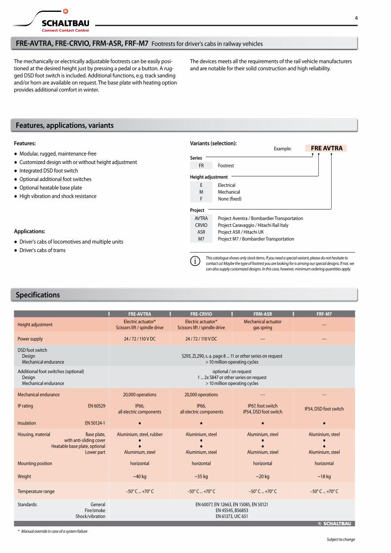
FRE-AVTRA, FRE-CRVIO, FRM-ASR, FRF-M7 Footrests for driver's cabs in railway vehicles
Specifications
FRE-AVTRA FRE-CRVIO FRM-ASR FRF-M7
Height adjustment Electric actuator* Scissors lift / spindle drive
Electric actuator* Scissors lift / spindle drive
Mechanical actuator gas spring ---
Power supply 24 / 72 / 110 V DC 24 / 72 / 110 V DC --- ---
DSD foot switch Design Mechanical endurance
S293, ZL290, s. a. page 8 ... 11 or other series on request
> 10 million operating cycles
Additional foot switches (optional) Design Mechanical endurance
optional / on request 1 ... 2x S847 or other series on request
> 10 million operating cycles
Mechanical endurance 20,000 operations 20,000 operations --- ---
IP rating EN 60529 IP66, all electric components
IP66, all electric components
IP67, foot switch IP54, DSD foot switch IP54, DSD foot switch
Insulation EN 50124-1
Housing, material Base plate, with anti-sliding cover
Heatable base plate, optional Lower part
Aluminium, steel, rubber
Aluminium, steel
Aluminium, steel
Aluminium, steel
Aluminium, steel
Aluminium, steel
Aluminium, steel
Aluminium, steel
Mounting position horizontal horizontal horizontal horizontal
Weight ~40 kg ~35 kg ~20 kg ~18 kg
Temperature range –50° C ... +70° C –50° C ... +70° C –50° C ... +70° C –50° C ... +70° C
Standards: General Fire/smoke
Shock/vibration
EN 60077, EN 12663, EN 15085, EN 50121 EN 45545, BS6853 EN 61373, UIC 651
* Manual override in case of a system failure
Example: FRE AVTRA Series
FR Footrest
Height adjustment
EMF
ElectricalMechanicalNone (fixed)
Project
AVTRACRVIO
ASRM7
Project Aventra / Bombardier TransportationProject Caravaggio / Hitachi Rail ItalyProject ASR / Hitachi UKProject M7 / Bombardier Transportation
This catalogue shows only stock items. If you need a special variant, please do not hesitate to contact us! Maybe the type of footrest you are looking for is among our special designs. If not, we can also supply customized designs. In this case, however, minimum ordering quantities apply.
5
206.
5 ±2
356.
5 ±248
7 ±2
645.5 ±2646 ±2
150 ±
2
M6
Stroke 150 mm max.
Footrest height 206.5 mm min.
Footrest height 356.5 mm max.
DSD foot switch, 2x S826 series
Manual operation (emergency operation)15
°
337 ±
2
287.5 ±2
DSD foot switch
Footrest height 125 mm min.
Stroke 129 mm max.
Footrest height 290 mm max.
320 ±2
Manual operation (emergency operation)
448,6 ±2
330 ±2
170 ±
229
0 ±2
990 ±2
754 ±2
20°
120 ±
2
Subject to changeSubject to change / Dimensions in mm
FRE-AVTRA Electrical adjustable footrest for railway vehicles
FRE-CRVIO Electrical adjustable footrest for railway vehicles
Dimension diagram:
Dimension diagram:
6
446 ±212
5 ±2
162 ±
2
350 ±
2
312 ±
2
500 ±
2
275 ±
215
0 ±2
5°
446 ±2500 ±2
DSD foot switch, S293 series
Foot switch horn, 2x S847 series, IP67
Pedal for releasing the height adjustment
Footrest height 125 mm min.
Stroke 150 mm max.
Footrest height 275 mm max.
878 ±
2
18°
220 ±
2
251 ±2
504 ±2
655 ±2
Footrest height in front 220 mm
DSD foot switch, 3x S826 series
Foot switch horn
Removable hatchwith square key lock
Base plate heatable,controlled by adjustable thermostat
ConnectorsX1 port ITT Cannon
X2 port VBN3
M5
Subject to changeDimensions in mm / Subject to change
FRF-M7 Footrest for railway applications without height adjustment
FRM-ASR Mechanical adjustable footrest for railway vehicles
Dimension diagram::
Dimension diagram::
7
31
42
S13
14
2S1
46
90 121.
6
81
103
36
54.4
27.5
51
30
40.5
15.5
38
3.6 29
3.6 29
153.
114
3.6
59.5
6.5
153.
115
0.6
Mounting borings2x Ø6 mm
ActuatorS579 W: blackS579 WR: red
Stroke 3.6 mm
Cable outlet Ø16 mm
ActuatorS579 T: black
S579 TG: yellow
Stroke 3.6 mm
Cable outlet Ø16 mm
Mounting borings4x Ø5 mm
1818
50 50
S579 W, S579 WR series1x S814 b40
S579 T, S579 TG series1x S804 b40
Housingaluminium / gold
Housing aluminum die-cast / black
Subject to changeSubject to change / Dimensions in mm
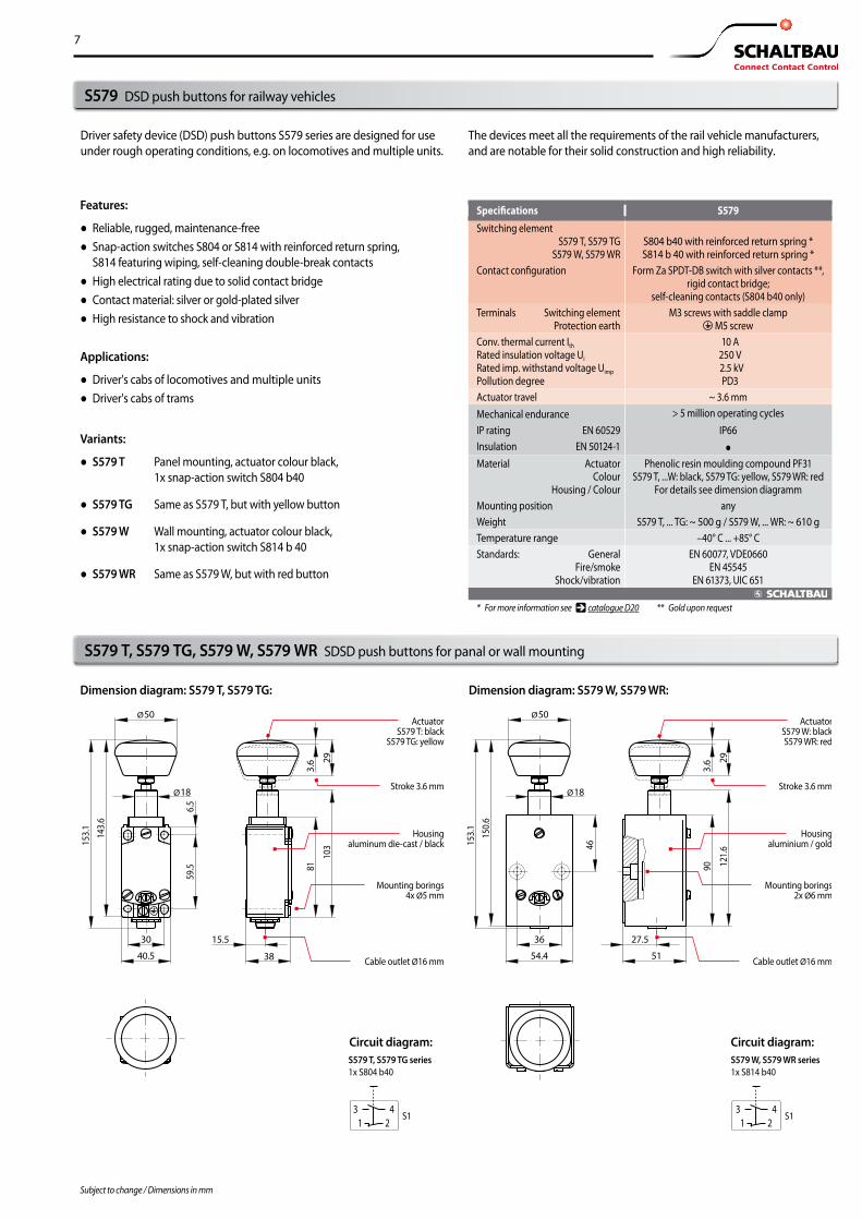
S579 DSD push buttons for railway vehicles
S579 T, S579 TG, S579 W, S579 WR SDSD push buttons for panal or wall mounting
Driver safety device (DSD) push buttons S579 series are designed for use under rough operating conditions, e.g. on locomotives and multiple units.
The devices meet all the requirements of the rail vehicle manufacturers, and are notable for their solid construction and high reliability.
Features:
● Reliable, rugged, maintenance-free ● Snap-action switches S804 or S814 with reinforced return spring,
S814 featuring wiping, self-cleaning double-break contacts ● High electrical rating due to solid contact bridge ● Contact material: silver or gold-plated silver ● High resistance to shock and vibration
Dimension diagram: S579 T, S579 TG: Dimension diagram: S579 W, S579 WR:
Applications:
● Driver's cabs of locomotives and multiple units ● Driver's cabs of trams
Variants:
● S579 T Panel mounting, actuator colour black, 1x snap-action switch S804 b40
● S579 TG Same as S579 T, but with yellow button
● S579 W Wall mounting, actuator colour black, 1x snap-action switch S814 b 40
● S579 WR Same as S579 W, but with red button
Specifications S579Switching element S579 T, S579 TG S579 W, S579 WR
S804 b40 with reinforced return spring * S814 b 40 with reinforced return spring *
Contact configuration
Form Za SPDT-DB switch with silver contacts **, rigid contact bridge;
self-cleaning contacts (S804 b40 only)Terminals Switching element
Protection earth M3 screws with saddle clamp
M5 screwConv. thermal current Ith Rated insulation voltage Ui Rated imp. withstand voltage Uimp Pollution degree
10 A 250 V 2.5 kV PD3
Actuator travel ~ 3.6 mmMechanical enduranceIP rating EN 60529Insulation EN 50124-1
> 5 million operating cyclesIP66●
Material Actuator Colour
Housing / Colour
Phenolic resin moulding compound PF31 S579 T, ...W: black, S579 TG: yellow, S579 WR: red
For details see dimension diagrammMounting position anyWeight S579 T, ... TG: ~ 500 g / S579 W, ... WR: ~ 610 gTemperature range –40° C ... +85° CStandards: General
Fire/smoke Shock/vibration
EN 60077, VDE0660 EN 45545
EN 61373, UIC 651
* For more information see catalogue D20 ** Gold upon request
Circuit diagram:Circuit diagram:
8
Subject to change
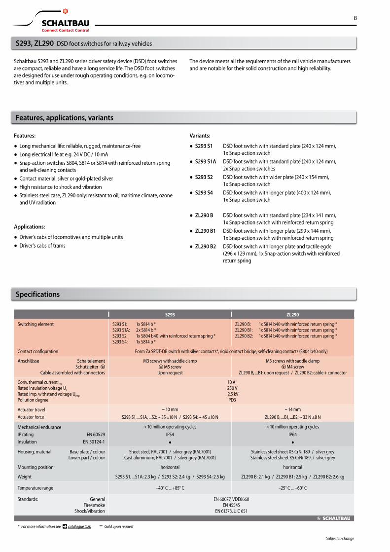
Features:
● Long mechanical life: reliable, rugged, maintenance-free ● Long electrical life at e.g. 24 V DC / 10 mA ● Snap-action switches S804, S814 or S814 with reinforced return spring
and self-cleaning contacts ● Contact material: silver or gold-plated silver ● High resistance to shock and vibration ● Stainless steel case, ZL290 only: resistant to oil, maritime climate, ozone
and UV radiation
Variants:
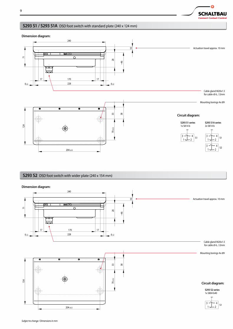
● S293 S1 DSD foot switch with standard plate (240 x 124 mm), 1x Snap-action switch
● S293 S1A DSD foot switch with standard plate (240 x 124 mm), 2x Snap-action switches
● S293 S2 DSD foot switch with wider plate (240 x 154 mm), 1x Snap-action switch
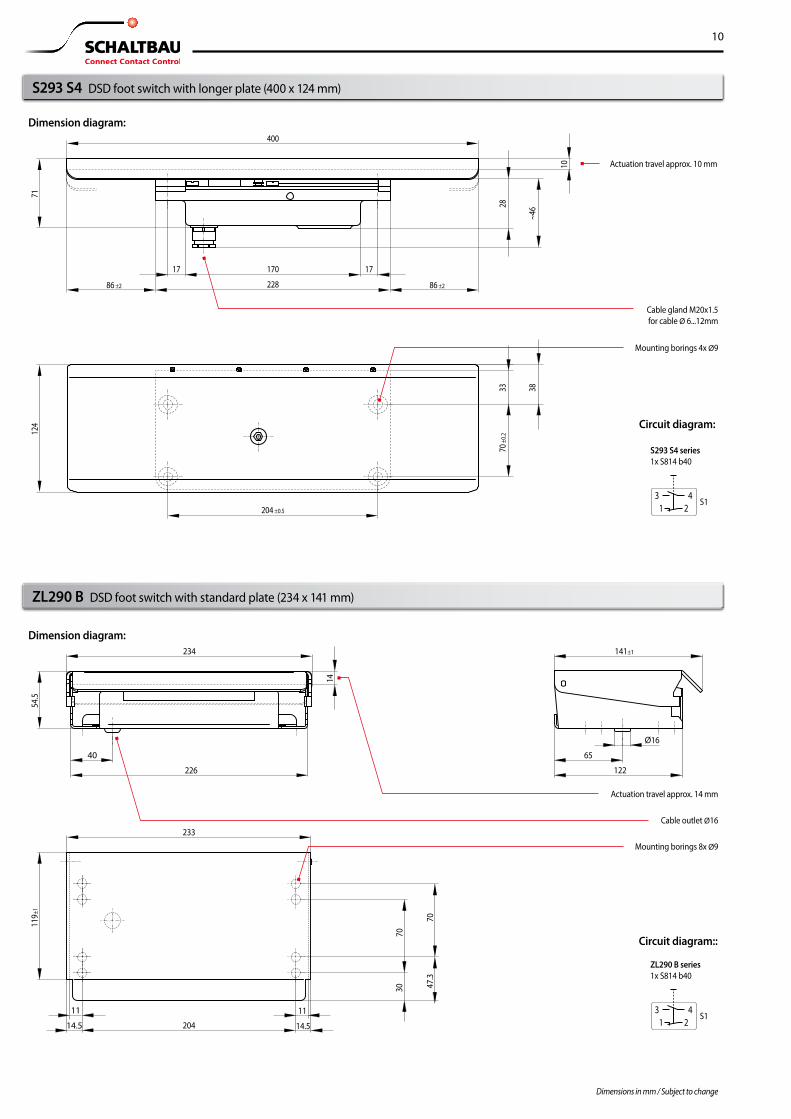
● S293 S4 DSD foot switch with longer plate (400 x 124 mm), 1x Snap-action switch
● ZL290 B DSD foot switch with standard plate (234 x 141 mm), 1x Snap-action switch with reinforced return spring
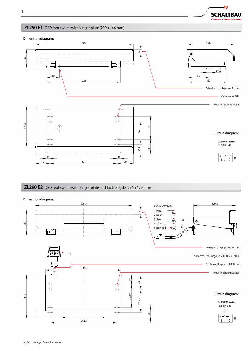
● ZL290 B1 DSD foot switch with longer plate (299 x 144 mm), 1x Snap-action switch with reinforced return spring
● ZL290 B2 DSD foot switch with longer plate and tactile egde (296 x 129 mm), 1x Snap-action switch with reinforced return spring
S293, ZL290 DSD foot switches for railway vehicles
Specifications
Features, applications, variants
Applications:
● Driver's cabs of locomotives and multiple units ● Driver's cabs of trams
S293 ZL290
Switching element
S293 S1: 1x S814 b * S293 S1A: 2x S814 b * S293 S2: 1x S804 b40 with reinforced return spring * S293 S4: 1x S814 b *
ZL290 B: 1x S814 b40 with reinforced return spring * ZL290 B1: 1x S814 b40 with reinforced return spring * ZL290 B2: 1x S814 b40 with reinforced return spring *
Contact configuration Form Za SPDT-DB switch with silver contacts*, rigid contact bridge; self-cleaning contacts (S804 b40 only)
Anschlüsse Schaltelement Schutzleiter Cable assembled with connectors
M3 screws with saddle clamp M5 screw
Upon request
M3 screws with saddle clamp M4 screw
ZL290 B, ...B1: upon request / ZL290 B2: cable + connector
Conv. thermal current Ith Rated insulation voltage Ui Rated imp. withstand voltage Uimp Pollution degree
10 A 250 V 2.5 kV PD3
Actuator travelActuator force
~ 10 mmS293 S1, ...S1A, ...S2: ~ 35 ±10 N / S293 S4: ~ 45 ±10 N
~ 14 mmZL290 B, ...B1, ...B2: ~ 33 N ±8 N
Mechanical endurance IP rating EN 60529Insulation EN 50124-1
> 10 million operating cyclesIP54●
> 10 million operating cyclesIP64●
Housing, material Base plate / colour Lower part / colour
Sheet steel, RAL7001 / silver grey (RAL7001) Cast aluminium, RAL7001 / silver grey (RAL7001)
Stainless steel sheet X5 CrNi 189 / silver grey Stainless steel sheet X5 CrNi 189 / silver grey
Mounting position horizontal horizontal
Weight S293 S1, ...S1A: 2.3 kg / S293 S2: 2.4 kg / S293 S4: 2.5 kg ZL290 B: 2.1 kg / ZL290 B1: 2.5 kg / ZL290 B2: 2.6 kg
Temperature range –40° C ... +85° C –25° C ... +60° C
Standards: General Fire/smoke
Shock/vibration
EN 60077, VDE0660 EN 45545
EN 61373, UIC 651
* For more information see catalogue D20 ** Gold upon request
Schaltbau S293 and ZL290 series driver safety device (DSD) foot switches are compact, reliable and have a long service life. The DSD foot switches are designed for use under rough operating conditions, e.g. on locomo-tives and multiple units.
The device meets all the requirements of the rail vehicle manufacturers and are notable for their solid construction and high reliability.
9
31
42
31
42
31
42
S1
S2
S1
124
71
240
204 ±0.5
228
170 17
6 ±26 ±2
17
70 ±
0.228
10
~46
33 38
Mounting borings 4x Ø9
Cable gland M20x1.5for cable-Ø 6...12mm
Actuation travel approx. 10 mm
S293 S1 series1x S814 b
S293 S1A series2x S814 b
31
42
S1
154
71
204 ±0.5
170 1717
70 ±
0.228
10
~46
33 38
Mounting borings 4x Ø9
Cable gland M20x1.5for cable Ø 6...12mm
Actuation travel approx. 10 mm
228 6 ±26 ±2
240
S293 S2 series1x S804 b40
Subject to changeSubject to change / Dimensions in mm
S293 S2 DSD foot switch with wider plate (240 x 154 mm)
S293 S1 / S293 S1A DSD foot switch with standard plate (240 x 124 mm)
Circuit diagram:
Dimension diagram:
Dimension diagram:
Circuit diagram:
10
31
42
S1
400
204 ±0.5
228
170 17
86 ±286 ±2
17
124
71
70 ±
0.228
10
~46
33 38
Mounting borings 4x Ø9
Cable gland M20x1.5for cable Ø 6...12mm
Actuation travel approx. 10 mm
S293 S4 series1x S814 b40
31
42
S1
234 141±1
7030
7047
.3
122
65
Ø16
204
233
14.5
1111
14.5
226
40
54.5
119±
1
14
Mounting borings 8x Ø9
Cable outlet Ø16
Actuation travel approx. 14 mm
ZL290 B series1x S814 b40
Subject to changeDimensions in mm / Subject to change
ZL290 B DSD foot switch with standard plate (234 x 141 mm)
S293 S4 DSD foot switch with longer plate (400 x 124 mm)
Circuit diagram:
Circuit diagram::
Dimension diagram:
Dimension diagram:
11
31
42
S1
296±1 129±1
204±2
30
20
4570
±0.1
570±0
.15
76±1
136±
1
56±1
233±1
1 2 3 4 5
Steckerbelegung 1 weiss
NC2 braun
5 grün-gelb
3 blau
NO4 schwarz
Mounting borings 8x Ø9
Cable length approx. 1,000 mm
Connector: 5 pol Wago No 231-105/037-000
Actuation travel approx. 14 mm
14
ZL290 B2 series1x S814 b40
31
42
S1
299
204
226
144±1
122
7032
.3
7047
.3
65
Ø16
1111
5045
40
5612
9±1
14ZL290 B1 series1x S814 b40
Mounting borings 8x Ø9
Cable outlet Ø16
Actuation travel approx. 14 mm
Subject to changeSubject to change / Dimensions in mm
ZL290 B2 DSD foot switch with longer plate and tactile egde (296 x 129 mm)
ZL290 B1 DSD foot switch with longer plate (299 x 144 mm)
Circuit diagram:
Circuit diagram:
Dimension diagram:
Dimension diagram:
Schaltbau GmbHFor detailed information on our products and services visit our website – or give us a call!
Schaltbau GmbH Hollerithstrasse 5 81829 Munich Germany
Phone +49 89 9 30 05-0 Fax +49 89 9 30 05-350 Internet www.schaltbau-gmbh.com e-Mail [email protected]
Connectors
■ Connectors manufactured to industry standards
■ Connectors to suit the special requirements of communications engineering (MIL connectors)
■ Charging connectors for battery-powered machines and systems
■ Connectors for railway engineering, including UIC connectors
■ Special connectors to suit customer requirements
Snap-action switches ■ Snap-action switches with positive opening operation
■ Snap-action switches with self-cleaning contacts
■ Enabling switches
■ Special switches to suit customer requirements
Contactors ■ Single and multi-pole DC contactors
■ High-voltage AC/DC contactors
■ Contactors for battery powered vehicles and power supplies
■ Contactors for railway applications
■ Terminal bolts and fuse holders
■ DC emergency disconnect switches
■ Special contactors to suit customer requirements
Electrics for rolling stock
■ Equipment for driver's cab
■ Equipment for passenger use
■ High-voltage switchgear
■ High-voltage heaters
■ High-voltage roof equipment
■ Equipment for electric brakes
■ Design and engineering of train electrics to customer requirements
with compliments:
RoHS2011/65/EC
Schaltbau GmbH manufactures in
compliance with RoHS.
The production facilities of Schaltbau GmbH have been IRIS certified since
2008.
Certified to DIN EN ISO 14001
since 2002. For the most recent certificate visit
our website.
Certified to DIN EN ISO 9001
since 1994. For the most recent certificate visit
our website.
Electrical Components and Systems for Railway Engineering and Industrial Applications
F2144/1808/1.0 Printed in Germany
We reserve the right to make technical alterations without prior notice.
For updated product information visit www.schaltbau-gmbh.com. Issued 08-2019
Electrical Components and Systems for Railway Engineering and Industrial Applications