electrochemical abuse testing
TRANSCRIPT

Sandia National Laboratories is a multimission laboratory managed and operated by National Technology and Engineering Solutions of Sandia LLC, a wholly owned
subsidiary of Honeywell International Inc. for the U.S. Department of Energy’s National Nuclear Security Administration under contract DE-NA0003525.
Electrochemical Abuse TestingJoshua Lamb, Leigh Anna M. Steele, Chris Grosso, Jerry
Quintana, Loraine Torres-Castro, June Stanley, Summer Ferreira and John Hewson
Sandia National Laboratories
Energy Storage Peer Review
San Diego, CA, October 11-12, 2017

Approach and Capabilities
2
Cell and Module TestingBattery Abuse Testing Laboratory (BATLab)
Battery Pack/System TestingThermal Test Complex (TTC) and Burnsite
Battery Calorimetry

Understanding Battery Safety
3
Materials R&D• Non-flammable electrolytes• Electrolyte salts• Coated active materials• Thermally stable materials
Testing• Electrical, thermal, mechanical abuse testing• Large scale thermal and fire testing (TTC)• Failure propagation testing on batteries/systems• Diagnostic techniques for battery state of stability • Development for DOE Vehicle Technologies and USABC
Simulations and Modeling• Multi-scale models for understanding thermal runaway• Validating vehicle crash and failure propagation models• Fire Simulations to predict the size, scope, and
consequences of battery fires
Procedures, Policy, and Regulation• USABC Abuse Testing Manual (SAND 2005-3123)• SAE J2464/UL 1642 procedures and standards• R&D programs with NHTSA/DOT to inform best
practices, policies, and requirements

Motivation for propagation testing
4
• Results of single cell nail penetration and 1S10P propagation test
• 26650 LFP cell• Single cell has relatively minor failure• Significant increase in intensity with a 10 cell pack

Failure Propagation: No Thermal Management
5
Failures initiated by mechanical insult to edge cell of COTS LiCoO2 packs (3Ah cells)
• Observed complete propagation when cell are close packed with no thermal management
• Successful initiation at Cell #1• Propagation to adjacent cells • Cascading failure to entire battery over 60 s
5 cell Battery
• • • • • •
C1
C1-2
C2-3
C3-4
C4-5
C5
TC layout
•
• •
•

Mitigation through de-rating cells
• 50% SOC no cell to cell propagation observed• Thermal runaway of initial cell failure also fairly minimal
• Limited propagation at 75%• Cell 2 went into thermal runaway following the failure of cell 1• Some other cell damage was observed but no high rate thermal runaway events seen
inn cells 3-5
0 5 10 15 200
50
100
150
200
250
300
Cell 1 T V
Cell 2 T V
Cell 3 T V
Cell 4 T V
Cell 5 T V
Av
g.
Te
mp
era
ture
(C
)
Time (min)
50% SOC
0
1
2
3
4
5
Vo
lta
ge
(V
)
0 5 10 15 200
50
100
150
200
250
300
Cell 1 T V
Cell 2 T V
Cell 3 T V
Cell 4 T V
Cell 5 T V
Avg
. T
em
pera
ture
(C
)
Time (min)
75% SOC
0
1
2
3
4
5
Vo
ltag
e (
V)

Limits to cell de-rating
7
• Full failure of pack observed starting at 80% SOC• Compared to unmitigated baseline, peak temperatures observed were only marginally
lower (550 °C vs 620 °C)• Total pack propagation observed after ~4 minutes vs ~80 seconds at 100% SOC

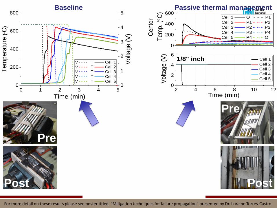
Failure Propagation Testing: Inclusion of Thermal Management
Methodology:
▪ Experimentally determine a reproducible thermal runaway initiator for each cell type
▪ Use this initiator to trigger a single cell thermal runaway failure in a battery
▪ Evaluate the propagation of that failure event
Experiment
▪ COTS LiCoO2 3Ah pouch cells
▪ 5 cells closely packed
▪ Failure initiated by a mechanical nail penetration along longitudinal axis of edge cell (cell 1)
▪ The current effort is focused on understanding extent of propagation with inclusion of passive thermal management in the form of heat sinks between pouch cells (aluminum and copper)
8
J. Lamb et al. J. Power Sources 283 (2015), 517-523 and C. J. Orendorff et al. SAND2014-17053
5 cell pack with aluminum or copper spacers between cells
Cell 1
For more detail on these results please see poster titled “Mitigation techniques for failure propagation” presented by Dr. Loraine Torres-Castro
0 1 2 3 4 50
200
400
600
800
V T Cell 1
V T Cell 2
V T Cell 3
V T Cell 4
V T Cell 5
Tem
pera
ture
(C
)
Time (min)
0
1
2
3
4
5
Volta
ge (
V)
0
200
400
600
2 4 6 8 10 120
2
4
6
Cell 1 O P1
Cell 2 P1 P2
Cell 3 P2 P3
Cell 4 P3 P4
Cell 5 P4 O
Ce
nte
r
Te
mp
. (
C)
1/8" inch
Vo
ltag
e (
V)
Time (min)
Cell 1
Cell 2
Cell 3
Cell 4
Cell 5
Pre
Post
Pre
Post
Baseline Passive thermal management
For more detail on these results please see poster titled “Mitigation techniques for failure propagation” presented by Dr. Loraine Torres-Castro

Discussion
▪ A cell may exhibit dramatically different failure response when in a string, module or pack than during single cell abuse testing
▪ Limiting the SOC can have a meaningful impact in propagating failure, however this comes at a significant cost to total energy storage
▪ Propagation can be mitigated through system engineering, however the results can be unpredictable. Further, electrical design will play a role in susceptibility to failure testing.
▪ Failure testing of large, complex systems is fairly resource intensive. Model based design presents a potential remedy to this, allowing us to infer a large amount of information from a relatively small number of tests.
10

Acknowledgements
• Christopher Orendorff
• Babu Chalamala
• Randy Shurtz
• Heather Barkholtz
• Kyle Fenton
• Eric Allcorn
• Lorie Davis
• Mani Nagasubramanian
• Jill Langendorf
• Imre Gyuk – US Department of Energy Office of Electricity
11