electromagnetic energy (eme) exposure report
TRANSCRIPT

ELECTROMAGNETIC ENERGY (EME) EXPOSURE REPORT
Site Name:
Site ID:
USID:
FA Location:
Site Type:
Location:
Latitude (NAD83):
Longitude (NAD83):
Report Completed:
AT&T M-RFSC
Prepared By:
n:
AD83):
(NAD83):
ompleted:
SC
Marin Avenue
CCL04554
101927
10113497
Rooftop
1035 San Pablo Avenue
Albany, CA 94706
37.885308
-122.297000
April 22, 2014
Casey Chan
Prepared for: AT&T Mobility
c/o Ericsson, Inc.
6140 Stoneridge Mall Rd.
Ste. 350
Pleasanton, CA 94588

OSC Engineering Inc. | www.OSCengineering.com | 858 436 4120 Page 2/19
Site Overview and Description
• The proposed antennas are mounted on a rooftop
• The site consists of three (3) sectors with a total of nine (9) antennas
• There are buildings within forty (40) feet of the transmitting antennas
• The site is co-located with Sprint antennas
Sector A Sector B Sector G
Azimuth 20º 345º 165º
Number of antennas 3 3 3
Bottom tip of antenna above
ground (ft.) 41.2 / 41.4 / 41.4 41.2 / 41.4 / 41.4 41.2 / 41.4 / 41.4
Bottomtip of antenna above
roof (ft.) 3.7 / 3.9 / 3.9 3.7 / 3.9 / 3.9 3.7 / 3.9 / 3.9
Technology UMTS / LTE UMTS / LTE UMTS / LTE
Antenna Make and Model
Commscope SBNHH-1D65A
Andrew SBNH-1D6565A
Commscope SBNHH-1D65A
Andrew SBNH-1D6565A
Commscope SBNHH-1D65A
Andrew SBNH-1D6565A
Sector Compliance
Compliant with
recommendations
Compliant with
recommendations
Compliant with
recommendations
Site Compliance Status
(FCC & AT&T Guidelines) Compliant with recommendations

OSC Engineering Inc. | www.OSCengineering.com | 858 436 4120 Page 3/19
Compliance Notes
Occupational Safety & Compliance Engineering (OSC Engineering) has been contracted by Ericsson to
conduct an RF (radio frequency) computer simulated analysis. The Federal Communications Commission
(FCC) has set limits on RF energy exposed to humans on a wireless cell site in order to ensure safety. The FCC
has also mandated that all RF wireless sites must be in compliance with the FCC limits and a compliance
check must be performed annually to ensure site compliance.
This report is an in depth analysis summarizing the results of the RF modeling provided to us by AT&T and in
relation to relevant FCC RF compliance standards. A reanalysis is recommended upon the site going on air.
OSC Engineering uses the FCC OET-65 as well as AT&T ND-00059 to make recommendations based on results
and information gathered from drawings and Radio Frequency Data Sheets.
For this report, OSC Engineering utilized Roofview® software for the theoretical analysis of the AT&T Cellular
Facility.
A site-specific compliance plan is recommended for each transmitting site. This report serves as a single piece
of the overall compliance plan.
Information utilized for this report: RFDS: SAN-FRANCISCO-SACRAMENTO_SAN-FRANCISCO_CNU4554_2014-LTE-
Next-Carrier_LTE...
Drawings: 25736-635-AA-CNU4554 IFC-REV0-TRANS

OSC Engineering Inc. | www.OSCengineering.com | 858 436 4120 Page 4/19
Compliance Recommendations & Results of the Proposed Site (theoretical simulation)
RF Sign(s) @ access point(s):
Information 1 Sign @ all roof access point(s) (to be posted)
RF Sign(s) and/or barriers @ antenna sector A:
To be installed: a 16’ X 12’ wide physical barrier with Caution and Information 1 Sign on physical barrier. Barriers
must be built a minimum of 6 feet away from roof edge to satisfy OSHA safety standards
RF Sign(s) and/or barriers @ antenna sector B:
To be installed: a 3’ X 4’ wide physical barrier with Caution and Information 1 Sign on physical barrier to block off
the entrance to the front of the antennas. Barriers must be built a minimum of 6 feet away from roof edge to satisfy
OSHA safety standards
RF Sign(s) and/or barriers @ antenna sector G:
To be installed: a Caution and Information 2 Sign in front of sector (optional)
Max RF Exposure Level from (AT&T antennas @ roof):
1762.1 % FCC General Population MPE Limit @ Sector A
1770.2 % FCC General Population MPE Limit @ Sector B
1770.2 % FCC General Population MPE Limit @ Sector G out into the air
Max RF Exposure Level simulated (cumulative roof / antenna level):
1773.0 % FCC General Population MPE Limit
Max RF Exposure Level simulated (AT&T antennas @ ground):
10.3 % FCC General Population MPE Limit
Max RF Exposure Level simulated (cumulative ground):
10.3 % FCC General Population MPE Limit

OSC Engineering Inc. | www.OSCengineering.com | 858 436 4120 Page 5/19
FCC Regulations and Guidelines from OET 65
When considering the contributions to field strength or power density from other RF sources, care should be taken to
ensure that such variables as reflection and re-radiation are considered. In cases involving very complex sites predictions
of RF fields may not be possible, and a measurement survey may be necessary The process for determining compliance
for other situations can be similarly accomplished using the techniques described in this section and in Supplement A to
this bulletin that deals with radio and television broadcast operations. However, as mentioned above, at very complex
sites measurements may be necessary.
In the simple example shown in the below diagram, it is desired to determine the power density at a given location X
meters from the base of a tower on which are mounted two antennas. One antenna is a CMRS antenna with several
channels, and the other is an FM broadcast antenna. The system parameters that must be known are the total ERP for
each antenna and the operating frequencies (to determine which MPE limits apply). The heights above ground level for
each antenna, H1 and H2, must be known in order to calculate the distances, R1and R2, from the antennas to the point of interest. 1
1 OET Bulletin 65, Evaluating Compliance with FCC Guidelines for Human Exposure to Radiofrequency Electromagnetic Fields, Page 37- 38
Antenna 2
Antenna 1
Point of Interest
H1H2
R1
R2
X
2 m
OSC Engineering Inc. | www.OSCengineering.com | 858 436 4120 Page 6/19
Computer Simulation Analysis
The Federal Communications Commission (FCC) governs the telecommunications services, facilities, and devices used by
the public, industrial and state organizations in the United States.
“RoofView® is a software analysis tool for evaluating radiofrequency (RF) field levels at roof-top telecommunications sites
produced by vertical collinear antennas of the type commonly used in the cellular, paging, PCS, ESMR and conventional
two-way radio communications services.”2
“RF near-field levels are computed from selected antennas by applying a cylindrical model that takes into account the
antenna’s aperture height, mounting height above the roof, azimuthal beam width for directional antennas and the
location of the antennas on the roof Resulting, spatially averaged power densities are expressed as a percentage of a
user selectable exposure limit depending on frequency. The entire roof is composed of one-square-foot pixels and RF
fields are computed for each of these pixels for each selected antenna.”3
Computer simulations produced for clients are simulated with “Uptime = 100%”. This means that all transmitters associated
with an antenna are considered to be “on”. 4
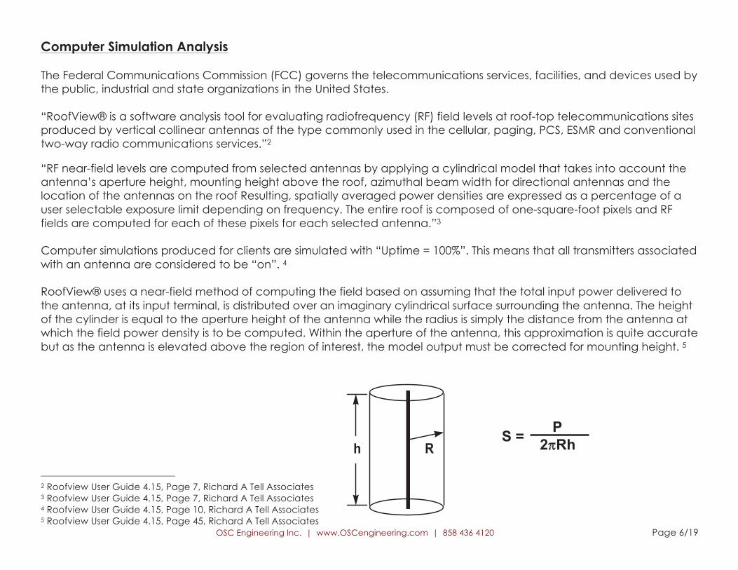
RoofView® uses a near-field method of computing the field based on assuming that the total input power delivered to
the antenna, at its input terminal, is distributed over an imaginary cylindrical surface surrounding the antenna. The height
of the cylinder is equal to the aperture height of the antenna while the radius is simply the distance from the antenna at
which the field power density is to be computed. Within the aperture of the antenna, this approximation is quite accurate
but as the antenna is elevated above the region of interest, the model output must be corrected for mounting height. 5
2 Roofview User Guide 4.15, Page 7, Richard A Tell Associates 3 Roofview User Guide 4.15, Page 7, Richard A Tell Associates 4 Roofview User Guide 4.15, Page 10, Richard A Tell Associates 5 Roofview User Guide 4.15, Page 45, Richard A Tell Associates
RhS =
P
2 Rh

OSC Engineering Inc. | www.OSCengineering.com | 858 436 4120 Page 7/19
Antenna Inventory All technical data and specifications shown below are collected from drawings and/or documents provided by the client, as well as from online
databases and/or a visit to this facility. Unknown wireless transmitting antennas are simulated using conservative values when information is not available.
Antenna
Operator /
Technology
Frequency
(MHz)
Total ERP
(Watts)
Antenna
Gain (dBd)
Antenna
Type
Antenna
Make Antenna Model
!" !#$#%&#' ()) ")*"+,- ")+./ 01234 5677896:3 ;<=>>?"@A/!
!" !#$#%&#' ".)) ")*"+,- ",+-/ 01234 5677896:3 ;<=>>?"@A/!
!B !#$#%CD#; ".)) "--A+A ",+(/ 01234 !2EF3G ;<=>?"@A/A/!
!- !#$#%CD#; */) "--A+A ""+(/ 01234 !2EF3G ;<=>?"@A/A/!
!- !#$#%CD#; ".)) "--A+A ",+(/ 01234 !2EF3G ;<=>?"@A/A/!
<" !#$#%&#' ()) ")*"+,- ")+./ 01234 5677896:3 ;<=>>?"@A/!
<" !#$#%&#' ".)) ")*"+,- ",+-/ 01234 5677896:3 ;<=>>?"@A/!
<B !#$#%CD#; ".)) "--A+A ",+(/ 01234 !2EF3G ;<=>?"@A/A/!
<- !#$#%CD#; */) "--A+A ""+(/ 01234 !2EF3G ;<=>?"@A/A/!
<- !#$#%CD#; ".)) "--A+A ",+(/ 01234 !2EF3G ;<=>?"@A/A/!
H" !#$#%&#' ()) ")*"+,- ")+./ 01234 5677896:3 ;<=>>?"@A/!
H" !#$#%&#' ".)) ")*"+,- ",+-/ 01234 5677896:3 ;<=>>?"@A/!
HB !#$#%CD#; ".)) "--A+A ",+(/ 01234 !2EF3G ;<=>?"@A/A/!
H- !#$#%CD#; */) "--A+A ""+(/ 01234 !2EF3G ;<=>?"@A/A/!
H- !#$#%CD#; ".)) "--A+A ",+(/ 01234 !2EF3G ;<=>?"@A/A/!
Azimuth
(IT)
Antenna
Aperture (ft)
Horizontal
Beamwidth
B) ,+/* AA
B) ,+/* A/
B) ,+B, /*
B) ,+B, AA
B) ,+B, /*
-,/ ,+/* AA
-,/ ,+/* A/
-,/ ,+B, /*
-,/ ,+B, AA
-,/ ,+B, /*
"A/ ,+/* AA
"A/ ,+/* A/
"A/ ,+B, /*
"A/ ,+B, AA
"A/ ,+B, /*
Ground
(Z) (ft)
Rooftop
(Z) (ft)
,"+B -+(
,"+B -+(
,"+, -+.
,"+, -+.
,"+, -+.
,"+B -+(
,"+B -+(
,"+, -+.
,"+, -+.
,"+, -+.
,"+B -+(
,"+B -+(
,"+, -+.
,"+, -+.
,"+, -+.

OSC Engineering Inc. | www.OSCengineering.com | 858 436 4120 Page 8/19
Antenna
Operator /
Technology
Frequency
(MHz)
Total ERP
(Watts)
Antenna
Gain (dBd)
Antenna
Type
Antenna
Make Antenna Model
Azimuth
(!T)
Antenna
Aperture (ft)
Horizontal
Beamwidth
Ground
(Z) (ft)
Rooftop
(Z) (ft)
!" #$%&'( )** +,-./ "- Panel 0'1'23' 0'1'23'
!- #$%&'( ",** 45-./ "/ Panel 0'1'23' 0'1'23'
!5 #$%&'( )** +,-./ "- Panel 0'1'23' 0'1'23'
6" #$%&'( )** +,-./ "- Panel 0'1'23' 0'1'23'
6- #$%&'( ",** 45-./ "/ Panel 0'1'23' 0'1'23'
65 #$%&'( )** +,-./ "- Panel 0'1'23' 0'1'23'
7/ 7 4/
7/ 7 4/
7/ 7 4/
"4* 7 4/
"4* 7 4/
"4* 7 4/
7- *
7- *
7- *
7- *
7- *
7- *

OSC Engineering Inc. | www.OSCengineering.com | 858 436 4120 Page 9/19
Theoretical Simulation Result Diagram – Cumulative Ground Level (Max Emission = 10.3% GP)
For the purpose of theoretical
simulation, OSC Engineering
models antennas as if they are
operating at full power (100%
capacity). This assumption yields
more conservative (higher)
results. On-site measurements
may yield different results, as
antennas do not always operate
at full capacity. To the right is a
result diagram of the site in
question. The diagram is a color-
coded map per ND-00059 levels,
which coincide with FCC MPE
Limits. Any exposure resulting in a
level higher than 100% exceeds
the Limits and requires further
action, such as barriers. A level
exceeding 100% does not make
a site out of compliance. All
results are given in General
Population percentages even
when a site may be considered
Occupational.

OSC Engineering Inc. | www.OSCengineering.com | 858 436 4120 Page 10/19
Theoretical Simulation Result Diagram – Cumulative Roof Level (Max Emission = 1773.0% GP)

OSC Engineering Inc. | www.OSCengineering.com | 858 436 4120 Page 11/19
Theoretical Simulation Result Diagram – AT&T Mobility only Ground Level (Max Emission = 10.3% GP)

OSC Engineering Inc. | www.OSCengineering.com | 858 436 4120 Page 12/19
Theoretical Simulation Result Diagram – AT&T Mobility only Roof Level (Max Emission = 1770.2% GP)

OSC Engineering Inc. | www.OSCengineering.com | 858 436 4120 Page 13/19
Certification
The undersigned is a Professional Engineer, holding a California Registration No. 19677
Reviewed and approved by:
John B. Bachoua, PE
Date: April 22, 2014
The engineering and design of all related structures as well as the impact of the antennas on the
structural integrity of the design are specifically excluded from this report’s scope of work. This report’s
scope of work is limited to an evaluation of the Electromagnetic Energy (EME) RF emissions field
generated by the antennas listed in this report. When client and others have supplied data, it is
assumed to be correct.

OSC Engineering Inc. | www.OSCengineering.com | 858 436 4120 Page 14/19
FCC MPE Limits (from OET-65)
OSC Engineering uses the FCC’s and clients’ guidelines to model the computer simulation. Explained in detail in Office of
Engineering & Technology, Bulletin No. 65 (“OET-65”) “Evaluating Compliance with FCC Guidelines for Human Exposure to
Radiofrequency Electromagnetic Radiation”.
Occupational/controlled6 exposure limits apply to situations in which persons are exposed as a consequence of their
employment and in which those persons who are exposed have been made fully aware of the potential for exposure
and can exercise control over their exposure. Occupational/controlled exposure limits also apply where exposure is of
a transient nature as a result of incidental passage through a location where exposure levels may be above general
population/uncontrolled limits (see below), as long as the exposed person has been made fully aware of the potential
for exposure and can exercise control over his or her exposure by leaving the area or by some other appropriate
means. As discussed later, the occupational/controlled exposure limits also apply to amateur radio operators and
members of their immediate household.
General population/uncontrolled7 exposure limits apply to situations in which the general public may be exposed or in
which persons who are exposed as a consequence of their employment may not be made fully aware of the
potential for exposure or cannot exercise control over their exposure. Therefore, members of the general public would
always be considered under this category when exposure is not employment-related, for example, in the case of a
telecommunications tower that exposes persons in a nearby residential area.
6 OET-65 “Evaluating Compliance with FCC Guidelines for Human Exposure to Radiofrequency Electromagnetic Fields pg. 9.
7 OET-65 “Evaluating Compliance with FCC Guidelines for Human Exposure to Radiofrequency Electromagnetic Fields pg. 9.
OSC Engineering Inc. | www.OSCengineering.com | 858 436 4120 Page 15/19
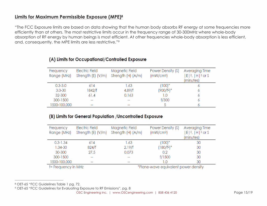
Limits for Maximum Permissible Exposure (MPE)8
“The FCC Exposure limits are based on data showing that the human body absorbs RF energy at some frequencies more
efficiently than at others. The most restrictive limits occur in the frequency range of 30-300MHz where whole-body
absorption of RF energy by human beings is most efficient. At other frequencies whole-body absorption is less efficient,
and, consequently, the MPE limits are less restrictive.”9
8 OET-65 “FCC Guidelines Table 1 pg. 72. 9 OET-65 “FCC Guidelines for Evaluating Exposure to RF Emissions”, pg. 8

OSC Engineering Inc. | www.OSCengineering.com | 858 436 4120 Page 16/19
Limits for Maximum Permissible Exposure (MPE) continued 10
“MPE Limits are defined in terms of power density (units of milliwatts per centimeter squared: mW/cm2), electric field
strength (units of volts per meter: V/m) and magnetic field strength (units of amperes per meter: A/m). In the far-field of a
transmitting antenna, where the electric field vector (E), the magnetic field vector (H), and the direction of propagation
can be considered to be all mutually orthogonal (“[plane-wave” conditions], these quantities are related by the
following equation:
10 OET-65 “FCC Guidelines Table 1 pg. 72.

OSC Engineering Inc. | www.OSCengineering.com | 858 436 4120 Page 17/19
Limitations
OSC Engineering completed this evaluation analysis based on information and data provided by the client. The data
provided by the client is assumed to be accurate. Estimates of the unknown, standard, and additional transmitting sites
are noted and based on FCC regulation and client requirements. These are estimated to the best of our professional
knowledge. This report is completed by OSC Engineering to determine whether the wireless communications facility
complies with the Federal Communications Commission (FCC) Radio Frequency (RF) Safety Guidelines. The Office of
Engineering and Technology (OET-65) Evaluating Compliance with FCC Guidelines for Human Exposure to
Radiofrequency Electromagnetic Radiation has been prepared to provide assistance in determining whether proposed
or existing transmitting facilities, operations or devices comply with limits for human exposure to radiofrequency (RF) fields
adopted by the Federal Communications Commission (FCC)11. As each site is getting upgraded and changed, this
report will become obsolete as this report is based on current information per the client, per the date of the report. Use of
this document will not hold OSC Engineering Inc. nor it’s employees liable legally or otherwise. This report shall not be used
as a determination as to what is safe or unsafe on a given site. All workers or other people accessing any transmitting site
should have proper EME awareness training. This includes, but is not limited to, obeying posted signage, keeping a
minimum distance from antennas, watching EME awareness videos and formal classroom training.
11 OET-65 “FCC Guidelines for Evaluating Exposure to RF Emissions”, pg. 1

OSC Engineering Inc. | www.OSCengineering.com | 858 436 4120 Page 18/19
EH&S and OSHA Barrier Consideration Environmental, Health and Safety (EH&S) guidelines prohibit construction of RF safety barriers that extend to, or are within the 6-ft
setback from, unprotected roof edges but do not meet the OSHA fall protection requirements of 29 CFR 1910.23 and 29 CFR
1926.500 through 1926.503. The following details are intended to assist AT&T RF safety engineers and RSVs in meeting the AT&T
Mobility RF safety compliance guidelines as defined in ND-00059. Whereas, AT&T employees and contractors working within 6 ft. from
an unprotected roof edge must follow OSHA guidelines with respect to fall protection and roof line safety.12
For Clarity: Unprotected roof edge refers to a parapet less than thirty-six (36) inches in height.
12
RF Safety Barrier 6-ft Rule v3_ehscmts_EHS cmts_ws, “Installing Radio Frequency (RF) safety barriers on roofs with unprotected edges job aid” Page 1 Overview

OSC Engineering Inc. | www.OSCengineering.com | 858 436 4120 Page 19/19
RECOMMENDATIONS
•Access Point
Information 1 Sign @ all
roof access point(s) (to
be posted)
•AT&T Sector A
To be installed: a 16’ X 12’
wide physical barrier with
Caution and Information
1 Sign on physical barrier.
Barriers must be built a
minimum of 6 feet away
from roof edge to satisfy
OSHA safety standards
•AT&T Sector B
To be installed: a 3’ X 4’
wide physical barrier with
Caution and Information
1 Sign on physical barrier
to block off the entrance
to the front of the
antennas. Barriers must be
built a minimum of 6 feet
away from roof edge to
satisfy OSHA safety
standards
•AT&T Sector G
To be installed: a Caution
and Information 2 Sign in
front of sector (optional)