electromechanical analogy approach to modeling analogy approach to modeling and analysis of air...
TRANSCRIPT

Sensors & Transducers, Vol. 25, Special Issue, December 2013, pp. 226-232
226
SSSeeennnsssooorrrsss &&& TTTrrraaannnsssddduuuccceeerrrsss
© 2013 by IFSAhttp://www.sensorsportal.com
Electromechanical Analogy Approach to Modeling and Analysis of Air Suspension with Auxiliary Chamber
1 Xing Xu, 1 Zhongxing Li, 2 Xiaoli Cui, 1 Minghong Gao
1 Jiangsu University, 301 Xuefu Road, Zhenjiang, Jiangsu Province, 212013, China 2 Hunan Institute of Technology, 18 Henghua Road, Hengyang, Hunan Province, 412002, China
Tel.: 86-511-88782845, fax: 86-511-88782845 E-mail: [email protected]
Received: 16 September 2013 /Accepted: 15 October 2013 /Published: 23 December 2013 Abstract: In order to effectively avoid the complexity and difficulty in analyzing the differential equations during the modeling process of air suspensions with auxiliary air chambers, electromechanical similarity theories were introduced, an equivalent electrical model was developed by analyzing parameters interaction relationship of the parts between electromechanical systems and mechanical system. The electrical model was verified and validated through comparisons and analysis between characteristic tests towards air suspension with auxiliary air chamber and simulation of equivalent electrical model. Based on the proposed electrical model, simulation was conducted to analyze main factors that influence the suspension performance, which could indicate that evaluation indexes of suspension system vary with the volume of auxiliary chamber and damping coefficient of damper. Analysis results show that both the volume of auxiliary chamber and damping coefficient of damper had considerable influence on air suspension performance, and the acceleration of sprung mass falls obviously with the auxiliary chamber increasing. Copyright © 2013 IFSA. Keywords: Auxiliary chamber, Air suspension, Electromechanical similarity, Electrical model, Factor analysis. 1. Introduction
Air spring system with auxiliary chambers is
constituted air spring with auxiliary chamber and the pipe, and it can obtain lower stiffness by adjusting the chamber volume [1]. The spring stiffness is closely related to the chamber volume, the suspension system’s performance could be improved by changing the volume of auxiliary air chambers. Recently, there are a few studies about air suspension system with auxiliary chamber. However, the major studies mainly focus on mathematical modeling which involves complex modeling processes [2].
In the early 1930s, electromechanical similarity theory has been applied in many ways such as mechanical vibration and control theory, because the
mechanical system and electrical system have same mathematical model essentially. There are two obvious advantages to analysis the vibration problem of mechanical system by electromechanical similarity theory [3-4], one is to bring in the theory of circuit analysis, network and control to mechanical system directly, besides, the design, modification or integrated of circuit system is much easier, and it is more convenient, fast, economy to simulation with electronic simulation software of SimPowerSystem [5-7]. To simplify the modeling process of mechanical system and avoid the complex mathematical equations, an equivalent electrical model of air suspension and its core component air spring with auxiliary chamber are proposed, and the corresponding relationship of suspension components
Article number P_SI_467
Sensors & Transducers, Vol. 25, Special Issue, December 2013, pp. 226-232
227
parameters between mechanical and electrical system is analyzed based on electromechanical similarity theory.
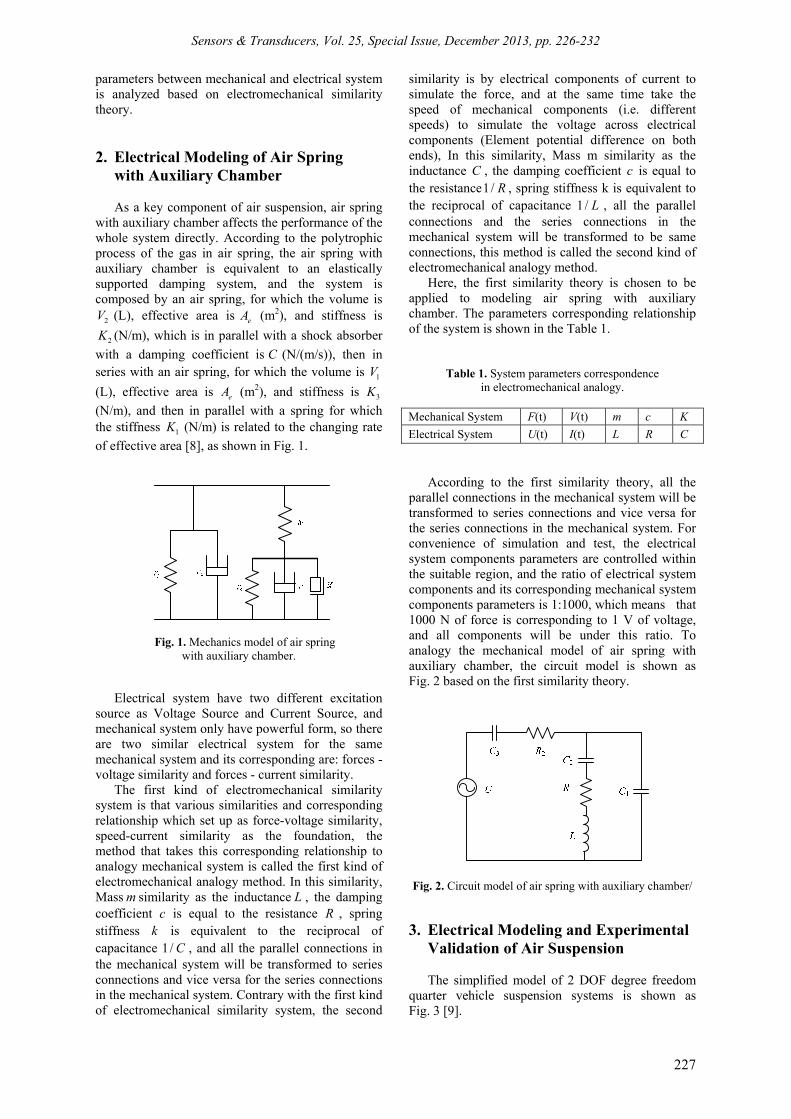
2. Electrical Modeling of Air Spring with Auxiliary Chamber As a key component of air suspension, air spring
with auxiliary chamber affects the performance of the whole system directly. According to the polytrophic process of the gas in air spring, the air spring with auxiliary chamber is equivalent to an elastically supported damping system, and the system is composed by an air spring, for which the volume is
2V (L), effective area is eA (m2), and stiffness is
2K (N/m), which is in parallel with a shock absorber with a damping coefficient is C (N/(m/s)), then in series with an air spring, for which the volume is 1V (L), effective area is eA (m2), and stiffness is 3K (N/m), and then in parallel with a spring for which the stiffness 1K (N/m) is related to the changing rate of effective area [8], as shown in Fig. 1.
Fig. 1. Mechanics model of air spring with auxiliary chamber.
Electrical system have two different excitation source as Voltage Source and Current Source, and mechanical system only have powerful form, so there are two similar electrical system for the same mechanical system and its corresponding are: forces - voltage similarity and forces - current similarity.
The first kind of electromechanical similarity system is that various similarities and corresponding relationship which set up as force-voltage similarity, speed-current similarity as the foundation, the method that takes this corresponding relationship to analogy mechanical system is called the first kind of electromechanical analogy method. In this similarity, Mass m similarity as the inductance L , the damping coefficient c is equal to the resistance R , spring stiffness k is equivalent to the reciprocal of capacitance 1/ C , and all the parallel connections in the mechanical system will be transformed to series connections and vice versa for the series connections in the mechanical system. Contrary with the first kind of electromechanical similarity system, the second
similarity is by electrical components of current to simulate the force, and at the same time take the speed of mechanical components (i.e. different speeds) to simulate the voltage across electrical components (Element potential difference on both ends), In this similarity, Mass m similarity as the inductance C , the damping coefficient c is equal to the resistance1/ R , spring stiffness k is equivalent to the reciprocal of capacitance 1/ L , all the parallel connections and the series connections in the mechanical system will be transformed to be same connections, this method is called the second kind of electromechanical analogy method.
Here, the first similarity theory is chosen to be applied to modeling air spring with auxiliary chamber. The parameters corresponding relationship of the system is shown in the Table 1.
Table 1. System parameters correspondence in electromechanical analogy.
Mechanical System F(t) V(t) m c K Electrical System U(t) I(t) L R C
According to the first similarity theory, all the
parallel connections in the mechanical system will be transformed to series connections and vice versa for the series connections in the mechanical system. For convenience of simulation and test, the electrical system components parameters are controlled within the suitable region, and the ratio of electrical system components and its corresponding mechanical system components parameters is 1:1000, which means that 1000 N of force is corresponding to 1 V of voltage, and all components will be under this ratio. To analogy the mechanical model of air spring with auxiliary chamber, the circuit model is shown as Fig. 2 based on the first similarity theory.
Fig. 2. Circuit model of air spring with auxiliary chamber/
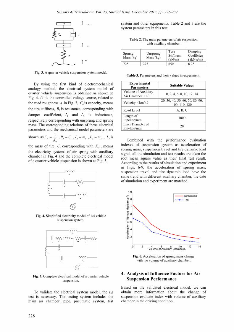
3. Electrical Modeling and Experimental Validation of Air Suspension The simplified model of 2 DOF degree freedom
quarter vehicle suspension systems is shown as Fig. 3 [9].
Sensors & Transducers, Vol. 25, Special Issue, December 2013, pp. 226-232
228
Fig. 3. A quarter vehicle suspension system model.
By using the first kind of electromechanical analogy method, the electrical system model of quarter vehicle suspension is obtained as shown in Fig. 4. U is the controlled voltage source, related to the road roughness q in Fig. 3, 4C is capacity, means the tire stiffness, 3R is resistance, corresponding with damper coefficient, 1L and 2L is inductance, respectively corresponding with unsprung and sprung mass. The corresponding relations of these electrical parameters and the mechanical model parameters are
shown as 41
t
CK
= , 3R C= , 1 1L m= , 2 2L m= , 3L is
the mass of tire. aC corresponding with aK , means the electricity systems of air spring with auxiliary chamber in Fig. 4 and the complete electrical model of a quarter vehicle suspension is shown as Fig. 5.
Fig. 4. Simplified electricity model of 1/4 vehicle suspension system.
Fig. 5. Complete electrical model of a quarter vehicle suspension.
To validate the electrical system model, the rig
test is necessary. The testing system includes the main air chamber, pipe, pneumatic system, test
system and other equipments. Table 2 and 3 are the system parameters in this test.
Table 2. The main parameters of air suspension with auxiliary chamber.
Sprung Mass (kg)
Unsprung Mass (kg)
Tyre Stiffness (kN/m)
Damping Coefficient (kN·s/m)
725 275 650 6.25
Table 3. Parameters and their values in experiment.
Experimental Parameters Suitable Values
Volume of Auxiliary Air Chamber(L) 0, 2, 4, 6, 8, 10, 12, 14
Velocity(km/h) 20, 30, 40, 50, 60, 70, 80, 90, 100, 110, 120
Road Level A, B, C Length of Pipeline/mm 1000
Inner Diameter of Pipeline/mm 20
Combined with the performance evaluation indexes of suspension system as acceleration of sprung mass, suspension travel and tire dynamic load signal, all the simulation and test results are taken the root mean square value as their final test result. According to the results of simulation and experiment in Figs. 6-9, the acceleration of sprung mass, suspension travel and tire dynamic load have the same trend with different auxiliary chamber, the date of simulation and experiment are matched.
0 2 4 6 8 10 12 14
1.3
1.4
1.5
1.6
1.7
1.8
1.9
Volume of Auxiliary Chamber/L
Acc
eler
atio
n of
Spr
ung
Mas
s/(m
/s2 )
SimulationTest
Fig. 6. Acceleration of sprung mass change with the volume of auxiliary chamber.
4. Analysis of Influence Factors for Air Suspension Performance
Based on the validated electrical model, we can obtain more information about the change of suspension evaluate index with volume of auxiliary chamber in the driving condition.

Sensors & Transducers, Vol. 25, Special Issue, December 2013, pp. 226-232
229
0 5 10 15 20 250
0.2
0.4
0.6
0.8
1
1.2
1.4
1.6
1.8
2
Frequency/Hz
PS
D/�
m2 /s
3 �
SimulationTest
Fig. 7. Frequency domain of acceleration.
0 2 4 6 8 10 12 146.5
7
7.5
8
8.5
9
9.5
10x 10-3
Volume of Auxiliary Chamber/L
Sus
pens
ion
Trav
el/m
SimulationTest
Fig. 8. Suspension travel change with the volume of auxiliary chamber.
0 2 4 6 8 10 12 143
3.1
3.2
3.3
3.4
3.5
3.6
3.7
3.8
3.9
4
Volume of Auxiliary Chamber/L
Tire
Dyn
amic
Loa
d/kN
SimulationTest
Fig. 9. Tire dynamic load change with the volume of auxiliary chamber.
Fig. 10 shows that how would the volume effect acceleration of sprung mass at different speed. As shown in Fig. 10, the acceleration of sprung mass decreases when the volume of auxiliary chamber increases, and the change will gradually be stable when the volume of auxiliary chamber increases
more under different speeds. Moreover, the acceleration of sprung mass declines quickly with the volume of auxiliary chamber when the volume is less than 6L, and it declines slowly when the volume is more than 6L.
0 2 4 6 8 10 12 141
1.2
1.4
1.6
1.8
2
Volume of Auxiliary Chamber/L
Acc
eler
atio
n of
Spr
ung
Mas
s/(m
/s2 �
50km/h70km/h90km/h
Fig. 10. Acceleration change with the volume of auxiliary chamber.
Fig. 11 is the acceleration power spectral density of sprung mass changes under the condition of the volume 2L and 10L of auxiliary chamber which find that sprung mass acceleration power spectrum values decrease obviously with the volume of auxiliary chamber increasing, especially during the frequency of 0~5 Hz. So, the auxiliary chamber volume can effectively decrease acceleration of sprung mass, and improve the ride performance of vehicle.
0 5 10 15 20 250
0.5
1
1.5
2
Frequency/Hz
PS
D(m
2 /s3 )
2L10L
Fig. 11. Acceleration power spectrum change with the volumes 2L and 10L of auxiliary chamber.
Fig. 12 and 13 shows that how would the volume effect suspension travel and tire dynamic load under different speeds. We find that suspension travel increases along with the volume of auxiliary chamber as shown in Fig. 12, but the increasing trend will be gradually smooth. It is no use to increase the volume of auxiliary chamber for suspension travel when the volume increases to the volume of 8L. Fig. 13 indicates that tire dynamic load decreases firstly and

Sensors & Transducers, Vol. 25, Special Issue, December 2013, pp. 226-232
230
then increases with the increase of auxiliary chamber volume, but the amplitude change is not obvious, the volume of 4L is the boundary. Totally, the volume change of auxiliary chamber has little impact on tire dynamic load.
0 2 4 6 8 10 12 143
3.5
4
4.5
5
5.5
6
6.5
7x 10⁻³
Volume of Auxiliary Chamber/L
Sus
pens
ion
Trav
el/m
50km/h70km/h90km/h
Fig. 12. Suspension travel change with different volume of auxiliary chamber.
0 2 4 6 8 10 12 14
1.8
2
2.2
2.4
2.6
Volume of Auxiliary Chamber/L
Tire
Dyn
amic
Loa
d/kN
50km/h70km/h90km/h
Fig. 13. Tire dynamic load change with different volume of auxiliary chamber.
On the other hand, the damper is mainly used to suppress the vibration of spring respond and absorb the shock of road. In fact, the spring stiffness and damper coefficient is a pair of matching parameters, they react on each other. Small stiffness and damping can improve the riding comfort of vehicle, and the better control stability is obtained under big stiffness and damping. With the volume 14L of auxiliary chamber, the suspension performance indexes change with the damper coefficient are shown as Figs. 14 - 16.
Choose the different damper coefficients as simulation variable, and the value is respectively 3125 N·s/m, 6250 N·s/m, 12500 N·s/m and 25000 N·s/m. It is corresponding to the equivalent resistance in the electrical mode.
By analyzing the results in Figs. 14-16, we can see that the three suspension performance index have a great change under different damper coefficients.
20 30 40 50 60 70
1
1.5
2
2.5
3
3.5
4
4.5
Speed/(km/h)
Acc
eler
atio
n of
Spr
ung
Mas
s/(m
/s2 )
R3=3125
R3=6250
R3=12500
R3=25000
Fig. 14. Influence of different damping coefficient to acceleration.
20 30 40 50 60 702
4
6
8
10
12
14x 10-3
Speed/(km/h)
Sus
pens
ion
Trav
el/m
R3=3125
R3=6250
R3=12500
R3=25000
Fig. 15. Influence of different damping coefficient to suspension travel.
0.5 1 1.5 2 2.5
x 104
2.5
3
3.5
4
4.5
5
5.5
Damping coefficient/(N·s/m)
Tire
Dyn
amic
Loa
d/kN
30km/h50km/h70km/h
Fig. 16. Influence of different damping coefficient to tire dynamic load.
Fig. 14 shows the acceleration of sprung mass increases along with damper coefficient. When the speed is 60 km/h, the coefficient vary from

Sensors & Transducers, Vol. 25, Special Issue, December 2013, pp. 226-232
231
6250 N·s/m to 25000 N·s/m, and the acceleration of sprung mass increases from 2.27 m/s2 to 3.71 m/s2, and the growing rate is about 63 %. Because the damping ratio increases with damper coefficient, which makes suspension harden, the damping effect of suspension decreased. The damper will have greater inhibition to the spring when the coefficient increases, and the inertia force of sprung mass can be transferred in a short distance, so the suspension travel decreases with damper coefficient increasing. Fig. 15 also shows that the greater damper coefficient, the less effect of speed to suspension travel, which indicates that damper coefficient, has more influence to the suspension performance than that of speed.
The tire dynamic load decrease firstly and then increases with the magnified damper coefficient in Fig. 16. The value of tire dynamic load is directly related to vehicle's road friendliness, so it is necessary to find the damping coefficient which corresponding to the minimum value of tire dynamic load. Further simulation was conducted with electrical model of the quarter vehicle suspension with the method of interpolation simulation, the results shown in Fig. 17.
0 0.5 1 1.5 2 2.5
x 104
2.5
3
3.5
4
4.5
5
5.5
Damping Coefficient/(N·s/m)
Tire
Dyn
amic
Loa
d/kN
30km/h50km/h70km/h
Fig. 17. Influence of different damping coefficient to tire dynamic load.
As shown in Fig. 17, the minimum of tire dynamic load appeared at the damper coefficient of 8250~9250 N·s/m in any speed. Combined with Fig. 15 and 16, we know that a damper coefficient cannot satisfy all performance indexes of suspension system, and it is need to have a comprehensive evaluate for suspension performance to get the most suitable damper coefficient.
5. Conclusions Based on Electromechanical Analogy Theory, the
equivalent electrical model of the air spring with auxiliary chamber and the air suspension system was
developed. The comparative analysis was carried out between the characteristic test of one-quarter suspension system and the simulation results for electrical model of air spring with auxiliary volume, and the accuracy of the electrical model is verified by rig-testing. According to the analysis results, it has been found that when the auxiliary volume increases, the sprung mass acceleration reduced gradually, dynamic rate of suspension increased and dynamic load of tire changed a little. When the auxiliary volume is less than 6L, the sprung mass acceleration and dynamic rate of suspension changed more. When the auxiliary volume is more than 6L, the amount of change was no longer obvious. With damping coefficient of the shock absorber changed, all performance indexes of suspension had great changes. So, the suitable damping coefficient of the shock absorber should be determined only when the suspension performance is evaluated.
Acknowledgement This study was supported by the National Natural
Science Foundation of China under Grant No. 51105177, the Natural Science Foundation of Jiangsu Province under Grant No. BK20131255, the Research Fund for the Doctoral Program of Higher Education of China under Grant No. 20113227120015, the Scientific Research Foundation for Advanced Talents, Jiangsu University under Grant No. 11JDG047 and the Hunan Provincial Hunan Provincial Science and Technology Key Project under Grant No. 2012GK2013. The first author gratefully acknowledges these support agencies.
References [1]. S. H. Zhu, J. SH. Wang, M. N. Zhang. Study on
vibration characteristics of one scissors linkage seat with suspension of the air spring and auxiliary chamber, Journal of Vibration and Shock, Vol. 28, Issue 11, pp. 104-106.
[2]. R. L. Roebuck, A. R. Jomnes, D. Cebon, An investigation of air damping for heavy goods vehicles, International Journal of Heavy Vehicle Systems, Vol. 18, Issue 2, 2011, pp. 115-134.
[3]. L. Chen, X. L. Zhang, H. B. Jiang, Vehicle Suspension System Employing Inerter Based on Electrical-mechanical Analogy Theory, China Mechanical Engineering, Vol. 20, Issue 10, 2009, pp. 1248-1251.
[4]. P. Di Sia, Magnetic Force as Source of Electron Attraction: A Classical Model and Applications, Journal Mechatronics, Vol. 1, Issue 1, 2012, pp. 48-50.
[5]. L. Wang, X. R. Zhou, J. G. Wang, Application Research of Similarity of Mechanics to Electricity Robotic Dynamics Analysis, Journal of Harbin University of Science and Technology, Vol. 6, Issue 1, 2001, pp. 9-12.

Sensors & Transducers, Vol. 25, Special Issue, December 2013, pp. 226-232
232
[6]. M. Z. Q. Chen, C. Papageorgiou, F. Scheibe, et al., The Missing Mechanical Circuit Element, IEEE Circuits and Systems Magazine, Vol. 9, Issue 1, 2009, pp. 10-26.
[7]. C. Hong, K. Benkrid, X. Iturbe, H. Hussain, Efficient Run-Time System Support for High Performance Reliable Reconfigurable Systems, Journal of Computational Intelligence and Electronic Systems, Vol. 1, Issue 2, 2012, pp. 213-219 .
[8]. M. J. Zheng, X. Y. Chen, Y. Lin, Dynamical Model and Characteristics Analysis of Air Spring, Transactions of the Chinese Society for Agricultural Machinery, Vol. 39, Issue 5, 2008, pp. 10-14.
[9]. Y. J Ying, M. Fang, Z. N. Zhang, Integrated Control of the EPS and ASS of An Automobile Based on H∞/PID Scheme, Transactions of the Chinese Society for Agricultural Machinery, Vol. 38, Issue 11, 2007, pp. 6-11.
___________________
2013 Copyright ©, International Frequency Sensor Association (IFSA). All rights reserved. (http://www.sensorsportal.com)