electronic pushbutton locks - lsda · (only available for remote control electronic deadbolt) 1....
TRANSCRIPT

Electronic Pushbutton LocksEL730SLR
© 2017 IDN, Inc. All rights reserved.0817
USER S GUIDE’security technology
IMPORTANT SAFETY INSTRUCT ION
!1. To prevent damage to the finish, DO NOT use any abrasives, sharp objects or harsh chemical products containing alcohol, petroleum solvents, acids or acetone to clean this lockset.
2. To prevent damage to the sensitive electronic components, DO NOT allow any liquids to enter lockset while installing or cleaning.
1. Do not attempt to disassemble any internal components of this lockset as this WILL void the limited warranty.
2. Do not drop or hit /strike the lockset as excessive shock may result in permanent damage.
3. Do not use sharp objects to press key buttons.
4. It is Strongly recommended that you always create a written backup of the programming code and individual user codes. Please use the last page of this booklet as your reference.
5. For your Security, please remember to change this lockset's factory default programming code to a PERSONAL programming code prior to normal day to day use of this product.
6. It is STRONGLY recommended that you use only ALKALINE BATTERIES to operate this product.
CAUTION
01A

Electronic Pushbutton LocksEL730SLR
© 2017 IDN, Inc. All rights reserved.0817
!
!
ATTENTION
INSTRUCT IONS IMPORTANTES DE SECUR ITE
1. N’utilisez pas de produits abrasifs ou de produits chimiques contenant de l'alcool, du benzene, de l'acide chlorhydrique ou de l'acide nitrique, et evitez d'utiliser des objets tranchants ou abrasifs pour nettoyer cette serrure. 2. Ne laissez pas l'eau ou un liquide dans la serrure pendant le processus d'installation.
1. Ne tentez pas de demonter vous-memes les composants internes de la serrure. Vous courez le risque d'annuler la garantie limitee. 2. Ne laissez pas tomber la serrure. Un grand choc pourrait causer des dommages permanents.3. N’utilisez pas des epingles ou des objets tranchants pour appuyer sur le clavier. 4. Creez toujours une copie de sauvegarde des informations que vous souhaitez conserver (telles que le code de programmation et les codes d'utilisateur). Veuillez utiliser la derniere page de ce manuel comme reference.5. Veuillez changer le code de programmation avant d'utiliser cette serrure.6. Il est fortement recommandé que vous utilisez uniquement des piles alcalines pour utiliser ce produit.
!
!
01B
CONTENTS
MAIN OPERATING INSTRUCTIONS
PROGRAMMING CODE AND USER CODECOMPONENTSINSTALLATION INSTRUCTIONS
SETUP MODE
01. HOW TO CHANGE PROGRAMMING CODE
02. HOW TO ADD AN USER CODE
03. HOW TO ADD A PROXIMITY CARD (RFID)04. HOW TO ADD A REMOTE CONTROL (RADIO FREQUENCY, RF)
06. HOW TO DELETE AN INDIVIDUAL EXISTING USER CODE
07. HOW TO DELETE AN INDIVIDUAL EXISTING PROXIMITY CARD
08. HOW TO DELETE AN INDIVIDUAL EXISTING REMOTE CONTROL
09. HOW TO DELETE ALL EXISTING USER CODES AT ONCE
10. HOW TO DELETE ALL EXISTING PROXIMITY CARDS/ REMOTE CONTROLS AT ONCE
02A
03
25
35
26
2728
29
31
33
32
34
050608
05. HOW TO ADD A SINGLE-USE USER CODE/ PROXIMITY CARD/ REMOTE CONTROL

Electronic Pushbutton LocksEL730SLR
© 2017 IDN, Inc. All rights reserved.0817
11. HOW TO DISABLE ALL EXISTING USER CODES / PROXIMITY CARDS / REMOTE CONTROLS (VACATION MODE)
36
12. HOW TO DISABLE BUTTON SOUND (MUTE MODE)
14. HOW TO SETUP AUTO-LOCK TIME DELAY13. HOW TO ENABLE AUTO-LOCK MODE
15. HOW TO ENABLE DOUBLE AUTHORIZATION MODE16. HOW TO RESTORE FACTORY SETTING17. HOW TO REPLACE A BATTERY OF REMOTE CONTROL
OPERATION MODE
TROUBLESHOOTING GUIDELINE
DECLARATIONS AND SAFETY STATEMENTS
01. HOW TO LOCK (i.e. TO ENABLE AUTO-LOCK)02. HOW TO UNLOCK
03. SAFE MODE
DATA RECORDS
4344
45
46
5152
37
3938
404142
02B
CONTENTS
MAIN OPERATING INSTRUCTIONS
1 23 45 67 89 0C
LED Indicator
Keypad
1. Green light: Code entered is valid.
1. To unlock the lockset by entering a valid code.
Thumbturn
2. To program the lockset.
2. Red light: Code entered is invalid / Under setup mode.3. Yellow light: Low battery warning.※ All batteries should be replaced if yellow light flashes.
Lock Button
Cancel Button
03
C
3. When mis-typing codes during any process, press Cancel Button to cancel the wrong codes and re-enter the correct codes if the yellow light is on or keeps flashing.4. To lock the lockset by pressing Lock Button .
Key Override
To unlock the lockset by a valid key.
To lock or unlock the lockset manually.
LED Indicator
Keypad
Key Override
Thumbturn
This manual is intended for both Proximity Card Electronic Deadbolt and Remote Control Electronic Deadbolt.
Any description which is related to proximity card (RFID technology)can only be applied on Proximity Card Electronic Deadbolt.
Any description which is related to remote controller (RF technology) can only be applied on Remote Control Electronic Deadbolt.

Electronic Pushbutton LocksEL730SLR
© 2017 IDN, Inc. All rights reserved.0817
MAIN OPERATING INSTRUCTIONS
(only available for Proximity Card Electronic Deadbolt)1. Inductive zone is around the keypad.2. The proximity card we offer is the latest Radio Frequency Identification (RFID) technology, compatible with standard Mifare -13.56 MHz.3. Unlock the door by touching the inductive zone with the proximity card.
(Radio Frequency, RF) (only available for Remote Control Electronic Deadbolt)1. There is one unlock button and one lock button on the remote control.2. Effective range of the controller is designed to be within 15 meters (50 feet). However, the range could be affected by ambient temperature and humidity.3. The LED light of the remote control will be turned on when holding the Lock Button for over 3 seconds.
1 23 45 67 89 0C
Inductive Zone
04
LED Indicator
Lock Button
Unlock Button
Inductive Zone & RFID Card:
Remote Control:
PROGRAMMING CODE AND USER CODE
PROGRAMMING CODE
05
1. Only one programming code will be allowed. The lockset can be programmed only by entering the programming code.2. A programming code is restricted to 6-digits in length only. The pre-set programming code is 1-2-3-4-5-6 (factory setting). Please change it before operating the lockset. 3. The programming code can be used to unlock the lockset.
USER CODE
1. A user code can be from four (4) to six (6) digits in length.2. A user code can be changed (added or deleted) by accessing the setup mode.3. The lockset cannot be programmed by entering any of the user codes. 4. The lockset will be unlocked by entering one user code.
Note: User code capacity: 10 sets maximum. Proximity card capacity: 10 sets maximum. Remote control capacity: 10 sets maximum.

Electronic Pushbutton LocksEL730SLR
© 2017 IDN, Inc. All rights reserved.0817
COMPONENTS
P
Q
R
J
I
H G
ED
S
F
U
BK
L
M
N
OC
A
T
06
A. Exterior Assembly
H. 5/16” (7.8mm) Screw (2)
I. 13/16” (20mm) Screw (1)
J. Decorative Cover
K. Adjustable Latch (Square or radius faceplate or drive-in)
L. 6/8” (19mm) Wood Screw (4)
M. Strike Plate
N. Reinforced Strike Plate
O. Dust Box
B. Cable
C. Tailpiece
D. Mounting Plate
COMPONENTS
E. 1-1/4” (32mm) Screw (1)
G. Interior Assembly
F. 2-1/8” (54mm) Mounting Bolt (2)
P. 3” (76mm) Wood Screw (2)
Q. Key (2)
07
R. Drive in Collar (Optional)
S. Bottom Plate (Optional)
T. Square or Radius Faceplate (Optional)
U. Screw post

Electronic Pushbutton LocksEL730SLR
© 2017 IDN, Inc. All rights reserved.0817
INSTALLATION INSTRUCTIONS
08
Mark the Door with a Template Sheet (attached separately)Note: If the door is pre-drilled, please begin with page 13.
a.Use TEMPLATE to mark centerline on door for for deadbolt about 3” to 6” (75 mm to 150 mm) above the existing knob or lever.b.Stand so door swings towards you. Align template on centerline and fold template as shown.
Centerline
Mark the door edge approximately 3” to 6”( 75 mm to 150 mm ) above the entry knob or lever.
09
INSTALLATION INSTRUCTIONS
DRILL PILOT HOLESSelect a backset. Mark and drill pilot holes as shown below.
Drill a 1/8 pilot hole
Drill a 1/8 pilot hole

Electronic Pushbutton LocksEL730SLR
© 2017 IDN, Inc. All rights reserved.0817
10
INSTALLATION INSTRUCTIONS
DRILL HOLESa.Drill a 2-1/8” ( 54 mm) or 1-1/2” ( 38 mm ) hole on the door face from both sides to avoid wood splitting.
11
DRILL HOLESb.Drill a 1”( 25 mm ) hole on the door edge for the latch.c. Use the faceplate as a template for mortise and pilot holes. Chisel 1/8”( 3 mm) deep. Faceplate should fit flush.d. Install the appropriate latch type as shown below.
INSTALLATION INSTRUCTIONS
Note: For a drive-in latch, please refer to page 14.
d

Electronic Pushbutton LocksEL730SLR
© 2017 IDN, Inc. All rights reserved.0817
12
INSTALLATION INSTRUCTIONS
PREPARE DOOR JAMB AND INSTALL STRIKE PLATE
Door jamb hole dimension
Strike dimension
Note: The dust box and reinforced strike plate are optional. It is recommended to install both of them for maximum security.
13
LATCH BACKSET ADJUSTMENTLatch backset adjustment only needs to be made if your door needs a 2-3/4” ( 70 mm ) backset. Please follow diagrams below as referece.( Skip this if your door has a 2-3/8” ( 60 mm ) backset )
INSTALLATION INSTRUCTIONS
1.
3. 4.
2.

Electronic Pushbutton LocksEL730SLR
© 2017 IDN, Inc. All rights reserved.0817
1.
3. 4.
2.
14
INSTALLATION INSTRUCTIONS
DRIVE-IN COLLAR or FACEPLATE ADJUSTMENTIn addition to 2-3/8”( 60 mm ) or 2-3/4”( 70 mm ) adjustable backset,you may change the faceplate to drive-in collar.(If your door is not a drive-in latch type, please skip this step.)
15
INSTALLATION INSTRUCTIONS
INSTALL LATCH IN MORTISED AREA OR INSTALL DRIVE-IN LATCHIf the door is designed for a standard type latch, please install the latch with 13/16” (20mm) screws provided. If a drive-in latch is used, please tap it into the appropriate position.
13/16” (20 mm) screws
Faceplate
Backset
Drive-in Latch
Tap Latch FlushWood Block (not included)
(See 1B before installation of drive-in latch)

Electronic Pushbutton LocksEL730SLR
© 2017 IDN, Inc. All rights reserved.0817
Thread the cable through the hole and under the latch.
Thread the tailpiece through the latch in horizontal position.
5
16
Drill a 5/16”(ø8mm) hole on the door when the screw post is installed.
INSTALLATION INSTRUCTIONS
6
17
The bulged part of mounting plate must face toward the door.
Slide cable through the notch of mounting plate.
INSTALLATION INSTRUCTIONS

Electronic Pushbutton LocksEL730SLR
© 2017 IDN, Inc. All rights reserved.0817
7
E
F
18
INSTALLATION INSTRUCTIONS
Make sure the mounting plate is parallel with the edge of the door.
Fasten the mounting plate with 2-1/8” (54mm) screws*2 and 1-1/4” (32mm) screw*1.Note: Screw (E) is an optional screw. We recommend using screw (E) for the stability of the lockset.
8 REMOVE THE DECORATIVE COVER
1. Hold on the lip of the decorative cover.
19
INSTALLATION INSTRUCTIONS
2. Put the thumbs on the thumbturn.
3. Remove the decorative cover by pushing the thumbturn.

Electronic Pushbutton LocksEL730SLR
© 2017 IDN, Inc. All rights reserved.0817
INSTALLATION INSTRUCTIONS
9
20
Connect the cable into the connector port firmly.The metal connector side should face outside.Note: The red portion of the cable is aligned with the red portion of the connector port.
Cable
Connectorport
INSTALLATION INSTRUCTIONS
12The cable must be arranged as shown in the diagram.
21

Electronic Pushbutton LocksEL730SLR
© 2017 IDN, Inc. All rights reserved.0817
12
INSTALLATION INSTRUCTIONS
22
Insert 5/16” (7.8mm) screws (H) and tighten them.
Insert a 13/16” (20mm) screw (I) and tighten it.AA
AAA
A
AA
SETDEL
INSTALLATION INSTRUCTIONS
1 23 45 67 89 0C
AUTOMATIC - BOLT DIRECTION DETERMINATION
1. Press and hold [SET] button for over 2 seconds. The Red LED will light up and beep twice. You are now under setup mode.2. Enter 123456 (or current programming code) and then press button. Enter [00] and press button. The Red LED will light up for 10 seconds. The lockset will have the bolt direction set.
23
Note:After installing the lock on the door, do the bolt direction determination first and then restore it to the factory setting.

Electronic Pushbutton LocksEL730SLR
© 2017 IDN, Inc. All rights reserved.0817
We recommend to re-install the decorative cover after completing setup mode in page 25 to page 42.
24
INSTALLATION INSTRUCTIONS
If you want to remove the decorative cover, please hold the bottom of the decorative cover and pull it toward yourself.
AA
AAA
A
AA
SETDEL
SETUP MODE
HOW TO CHANGE PROGRAMMING CODE
Important:The pre-set programming code is 1-2-3-4-5-6.Please change the programming code before operating the lockset.
1 23 45 67 89 0C
25
Steps are as follows: 1. Press and hold [SET] button for over 2 seconds. The Red LED will light up and beep twice. You are now under setup mode.2. Enter 123456 (or current programming code) and then press button . Enter [10] and press button . Enter new programming code (six digits) and press button . The Red LED will light up for 10 seconds. The lockset will have the new programming code set.
Note: 1.The lockset will go back to the standby status if no button is pressed in 10 seconds after accessing setup mode.2.If you enter new programming code in 10 seconds after accessing setup mode, the last programming code will be stored in the lockset.
Electronic Pushbutton LocksEL730SLR
© 2017 IDN, Inc. All rights reserved.0817
AA
AAA
A
AA
SETDEL
HOW TO ADD AN USER CODE
1 23 45 67 89 0C
26
SETUP MODE
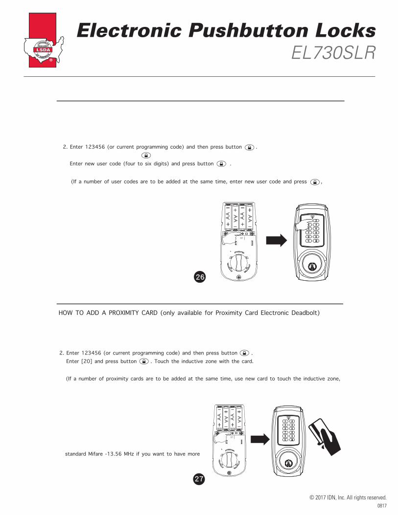
Steps are as follows: 1. Press and hold [SET] button for over 2 seconds. The Red LED will light up and beep twice. You are now under setup mode.2. Enter 123456 (or current programming code) and then press button . Enter [20]and press button . Enter new user code (four to six digits) and press button . The Red LED will light up for 10 seconds. The lockset will have the new user code set.
(If a number of user codes are to be added at the same time, enter new user code and press , and repeat above step prior to the indicator light timing out 10 seconds after the last press of a keypad button.)
Note: 1.The lockset will go back to the standby status if no button is pressed in 10 seconds after accessing setup mode.
AA
AAA
A
AA
SETDEL
1 23 45 67 89 0C
27
SETUP MODE
HOW TO ADD A PROXIMITY CARD (only available for Proximity Card Electronic Deadbolt)
Steps are as follows: 1. Press and hold [SET] button for over 2 seconds. The Red LED will light up and beep twice.You are now under setup mode.2. Enter 123456 (or current programming code) and then press button . Enter [20] and press button . Touch the inductive zone with the card. The Red LED will light up for 10 seconds. The lockset will have the new card set.
(If a number of proximity cards are to be added at the same time, use new card to touch the inductive zone, and repeat above step prior to the indicator light timing out 10 seconds after the last press of a keypad button.)
Note: 1.The lockset will go back to the standby status if no button is pressed in 10 seconds after accessing setup mode.2.Please use or purchase proximity cards compatible with standard Mifare -13.56 MHz if you want to have more than one proximity card.3.Proximity card capacity: 10 sets maximum.

Electronic Pushbutton LocksEL730SLR
© 2017 IDN, Inc. All rights reserved.0817
HOW TO ADD A SINGLE-USE USER CODE / PROXIMITY CARD / REMOTE CONTROL
29
SETUP MODE
Steps are as follows: 1. Press and hold [SET] button for over 2 seconds. The Red LED will light up and beep twice. You are now under setup mode.2. Enter 123456 (or current programming code) and then press button . 3. We recommend to turn on auto-lock mode according to page 38 before following the below steps to enable single-use user code/ remote control.
single-use Follow the below steps.
User code
Enter[21]
Enter user codes (4 digits)
Press any button on theremote control
Remote control
Proximity card
Pressbutton
Press button
User codes can be stored to5 sets
Remote controls can be stored to 5 sets
Touch the inductive zone
Proximity cards can be stored to 5 sets
30
Note:
1. The lockset will go back to the standby status if no button is pressed in 10 seconds after
accessing setup mode.
2. Single-use user code capacity: 5 sets maximum.
3. Single-use remote control capacity: 5 sets maximum.
4. Single-use proximity card capacity: 5 sets maximum.
5. Single-entry user code/ single-entry user remote control/ single-entry proximity card is only allowed to
work once and will become invalid after one-time use (entry).
6. Do not use your multiple-entry user code/ multiple-entry remote control/ multiple-entry proximity card
to facilitate single-entry operation, or your user code/ remote control/ proximity card will become invalid
after only one-time use (entry).
SETUP MODE

Electronic Pushbutton LocksEL730SLR
© 2017 IDN, Inc. All rights reserved.0817
AA
AAA
A
AA
SETDEL
1 23 45 67 89 0C
31
HOW TO DELETE AN INDIVIDUAL EXISTING USER CODE
SETUP MODE
Steps are as follows: 1. Press and hold [SET] button for over 2 seconds. The Red LED will light up and beep twice. You are now under setup mode.2. Enter 123456 (or current programming code) and then press button . Enter [30] and press button . Enter existing user code (that you wish to delete) and press button . The Red LED will light up for 10 seconds. The lockset will delete the existing user code that you do not want.
(If a number of user codes are to be deleted at the same time, enter each user code to be deleted and press on the keypad, and repeat above step prior to the indicator light timing out 10 seconds after the last press of akeypad button.)
Note: 1.The lockset will go back to the standby status if no button is pressed in 10 seconds after accessing setup mode.
32
HOW TO DELETE AN INDIVIDUAL EXISTING PROXIMITY CARD (only available for Proximity Card Electronic Deadbolt)
SETUP MODE
Steps are as follows: 1. Press and hold [SET] button for over 2 seconds. The Red LED will light up and beep twice. You are now under setup mode.2. Enter 123456 (or current programming code) and then press button . Enter [30] and press button . Put the card that you wish to delete to touch the inductive zone. The Red LED will light up for 10 seconds. The lockset will delete the existing card that you do not want.
(If a number of cards are to be deleted at the same time, use every card to touch the inductive zone consecutively prior to the indicator light timing out 10 seconds after the last press of a keypad button.)
Note: 1.The lockset will go back to the standby status if no button is pressed in 10 seconds after accessing setup mode.2.If any card is lost, for your safety, please delete all cards and re-add current cards excluding the lost one.

Electronic Pushbutton LocksEL730SLR
© 2017 IDN, Inc. All rights reserved.0817
SETUP MODE
HOW TO DELETE AN INDIVIDUAL EXISTING REMOTE CONTROL (only available for Remote Control Electronic Deadbolt)
Steps are as follows: 1. Press and hold [SET] button for over 2 seconds. The Red LED will light up and beep twice. You are now under setup mode.2. Enter 123456 (or current programming code) and then press button . Enter [30] and press button . Press any button on the remote control (that you wish to delete) and press button . The Red LED will light up for 10 seconds. The lockset will delete the existing remote control that you do not want.
(If a number of remote controls are to be deleted at the same time, press any button of the remote control that you want to delete and press button on the keypad, and repeat above step prior to theindicator light timing out 10 seconds after the last press of a keypad button.)
Note: 1.The lockset will go back to the standby status if no button is pressed in 10 seconds after accessing setup mode.2.If any remote control is lost, for your safety, please delete all remote controls and re-add current remote controls excluding the lost one.
33
AA
AAA
A
AA
SETDEL
1 24
5 67 89 0C
34
HOW TO DELETE ALL EXISTING USER CODES AT ONCE
SETUP MODE
Steps are as follows: 1. Press and hold [SET] button for over 2 seconds. The Red LED will light up and beep twice. You are now under setup mode.2. Enter 123456 (or current programming code) and then press button . Enter [40] and press button . Press and hold button until a beep is heard. The Red LED will light up for 10 seconds. The lockset will delete all existing user codes.
Note: 1.The lockset will go back to the standby status if no button is pressed in 10 seconds after accessing setup mode.
C
Electronic Pushbutton LocksEL730SLR
© 2017 IDN, Inc. All rights reserved.0817
AA
AAA
A
AA
SETDEL
1 23 45 67 89 0C
35
SETUP MODE
HOW TO DELETE ALL EXISTING PROXIMITY CARDS / REMOTE CONTROLS AT ONCE (only available for Proximity Card Electronic Deadbolt / Remote Control Electronic Deadbolt)
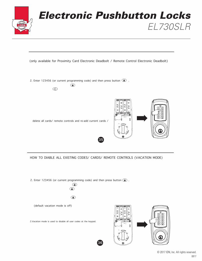
Steps are as follows: 1. Press and hold [SET] button for over 2 seconds. The Red LED will light up and beep twice. You are now under setup mode.2. Enter 123456 (or current programming code) and then press button . Enter [41] and press button . Press and hold button until a beep is heard. The Red LED will light up for 10 seconds. The lockset will delete all existing cards and remote controls.
Note: 1.The lockset will go back to the standby status if no button is pressed in 10 seconds after accessing setup mode.2.If any card / remote control is lost, for your safety, please delete all cards/ remote controls and re-add current cards / remote controls excluding the lost one.
C
AA
AAA
A
AA
SETDEL
1 23 45 67 89 0C
36
HOW TO DIABLE ALL EXISTING CODES/ CARDS/ REMOTE CONTROLS (VACATION MODE)
Steps are as follows: 1. Press and hold [SET] button for over 2 seconds. The Red LED will light up and beep twice. You are now under setup mode.2. Enter 123456 (or current programming code) and then press button . Enter [50] and press button . 3. Enter [0] and press button . The Red LED will light up for 10 seconds. The lockset will turn on vacation mode. 4. Enter [1] and press button . The Red LED will light up for 10 seconds. The lockset will turn off vacation mode. (default vacation mode is off)
SETUP MODE
Note: 1.The lockset will go back to the standby status if no button is pressed in 10 seconds after accessing setup mode.2.Vacation mode is used to disable all user codes at the keypad. If a valid user code is entered while the lock is in vacation mode, the lock will not be unlocked. If you will be away from your home for a period of, it is a good idea to use vacation mode to prevent repeated access attempts.

Electronic Pushbutton LocksEL730SLR
© 2017 IDN, Inc. All rights reserved.0817
AA
AAA
A
AA
SETDEL
1 23 45 67 89 0C
37
HOW TO DISABLE BUTTON SOUND (MUTE MODE)
SETUP MODE
Steps are as follows: 1. Press and hold [SET] button for over 2 seconds. The Red LED will light up and beep twice. You are now under setup mode.2. Enter 123456 (or current programming code) and then press button . Enter [60] and press button . 3. Enter [0] and press button . The Red LED will light up for 10 seconds. The lockset will turn on mute mode. 4. Enter [1] and press button . The Red LED will light up for 10 seconds. The lockset will turn off mute mode. (default mute mode is off)
Note: 1.The lockset will go back to the standby status if no button is pressed in 10 seconds after accessing setup mode.
38
AA
AAA
A
AA
SETDEL
1 23 45 67 89 0C
SETUP MODE
HOW TO ENABLE AUTO-LOCK MODE Steps are as follows: 1. Press and hold [SET] button for over 2 seconds. The Red LED will light up and beep twice. You are now under setup mode.2. Enter 123456 (or current programming code) and then press button . Enter [80] and press button . 3. Enter [0] and press button . The Red LED will light up for 10 seconds. The lockset will turn on auto-lock mode. 4. Enter [1] and press button . The Red LED will light up for 10 seconds. The lockset will turn off auto-lock mode. (default auto-lock mode is off)
Note: 1.The lockset will go back to the standby status if no button is pressed in 10 seconds after accessing setup mode.2.The lockset will auto-lock in 10 seconds (default value) without flashing and beeping after unlocking if you turn on auto-lock mode. 3.The lockset can still be locked by pressing button manually even if you turn on auto-lock mode.

Electronic Pushbutton LocksEL730SLR
© 2017 IDN, Inc. All rights reserved.0817
39
AA
AAA
A
AA
SETDEL
1 23 45 67 89 0C
SETUP MODE
HOW TO SETUP AUTO-LOCK TIME DELAY
Steps are as follows: 1. Press and hold [SET] button for over 2 seconds. The Red LED will light up and beep twice. You are now under setup mode.2. Enter 123456 (or current programming code) and then press button . Enter [70] and press button . Enter the seconds for delay time of auto-locking (10 to 90) and press button . The Red LED will light up for 10 seconds. The lockset will setup auto-lock time delay.
Note: 1.The lockset will go back to the standby status if no button is pressed in 10 seconds after accessing setup mode.2.The lockset will flash and beep three times if the seconds for delay time of auto-locking is not within 10 to 90 seconds.3.Default auto-lock time delay is 10 seconds.
AA
AAA
A
AA
SETDEL
1 23 45 67 89 0C
40
SETUP MODE
HOW TO ENABLE DOUBLE AUTHORIZATION MODE (only available for Proximity Card Electronic Deadbolt/ Remote Control Electronic Deadbolt)Steps are as follows: 1. Press and hold [SET] button for over 2 seconds. The Red LED will light up and beep twice. You are now under setup mode.2. Enter 123456 (or current programming code) and then press button . Enter [99] and press button . 3. Enter [0] and press button . The Red LED will light up for 10 seconds. The lockset will turn on double authorization mode. (When the double authorization mode is turned on, both user code and card, or both user code and remote control, must be authenticated to unlock the lockset)4. Enter [1] and press button . The Red LED will light up for 10 seconds. The lockset will turn off double authorization mode. (default double authorization mode is off)
Note: 1.The lockset will go back to the standby status if no button is pressed in 10 seconds after accessing setup mode.2.Please make sure that both user code and card, or both user code and remote control, are stored in the lockset before you turn on double authorization mode.

Electronic Pushbutton LocksEL730SLR
© 2017 IDN, Inc. All rights reserved.0817
AA A
A
AA A A
SETDEL
AA
AAA
A
AA
SETDEL
41
HOW TO RESTORE FACTORY SETTING
SETUP MODE
Steps are as follows: 1. Remove one battery from the battery pack. 2. Press and hold [SET] button and put the battery back. Keep holding [SET] button until a long beep and a short beep are heard. All functions will be restored back to factory setting.
Note: For your safety, restore factory setting after installing the lock on the door.All existing user codes/ cards/ remote controls will be deleted.Lock will be restored to the pre-set programming code of 1-2-3-4-5-6.Please change the programming code and add a new user code immediately before operating the lockset.
42
HOW TO REPLACE A BATTERY OF REMOTE CONTROL
Steps are as follows: 1. Loose two screws before opening the bottom shell.2. Take the PCB out.3. Push the battery out by inserting the tool into the crack between the PCB and the electrode terminal.4. Push into the new battery.5. Replace the PCB.6. Place the bottom shell back and tighten the screws.
SETUP MODE
Shell
Shell
PCB
CR2032 Battery
Screws
Battery box

Electronic Pushbutton LocksEL730SLR
© 2017 IDN, Inc. All rights reserved.0817
43
OPERATION MODE
HOW TO LOCK manually
Keypad: Press button to lock the door.Remote control: Press lock button to lock the door as shown. (only available for Remote Control Electronic Deadbolt) HOW TO LOCK automatically1. Auto-lock mode should be turned on and auto-lock time delay should be also set up.2. The lockset will be auto-locked in few seconds (default 10 seconds or the time you entered) after unlocking by using codes, card, or remote control.
Or Or
44
OPERATION MODE
HOW TO UNLOCK
1. Enter a valid code, touch the inductive zone with the card , or press unlock button on the remote control to unlock the lockset.2. When the double authorization mode is turned on, both user code and card, or both user code and remote control, must be authenticated to unlock the lockset.
C
C
C
Note: 1.If you cannot unlock the lockset by using card, especially the lockset is mounted outside or under the sun, please wakeup the lockset by pressing button on the keypad first, then unlock the lockset by using card.2.When you enter codes, and the keypad backlight will also be activated automatically under low light environment.3.Please press button to clear previous codes and re-enter codes if the previous codes are incorrect.4.If you do not press button to clear previous incorrect codes, the red LED will light up and you have to wait until the red LED lights off, then the lockset is allowed to re-enter codes.

Electronic Pushbutton LocksEL730SLR
© 2017 IDN, Inc. All rights reserved.0817
C
45
SAFE MODE
1. The keypad will be automatically deactivated for 1 minute after 4 wrong attempts.2. Wrong attempts will not be counted when you press button to clear previous incorrect codes before the red LED lights up.2. The deadbolt can be locked or unlocked by a valid traditional key under security.
OPERATION MODE
TROUBLESHOOTING GUIDELINE
The lockset did not operate correctly afterinstallation.
QUESTIONS ANSWERS
Feel a bump while turning of the motor?
1. Please rotate the thumbturn back and forth a few times.
1. Check center of strike hole for alignment with latch hole on the door to ensure free movement for the deadbolt.2. Make sure the tailpiece is properly inserted (in the horizontal position) in the latch.3. Do [AUTOMATIC -BOLT DIRECTION DETERMINATION].
46
Feel a bump while turning the thumbturn or the key?
1. Do not lock (or unlock) the door consecutively. This will cause a bump.2. If feeling a bump, press button while the door is unlocked to allow the motor to reposition.

Electronic Pushbutton LocksEL730SLR
© 2017 IDN, Inc. All rights reserved.0817
C
Keypad does not respond at all.
Programming code cannot be changed ?
1. Please complete the "HOW TO CHANGE PROGRAMMING CODE" process by inputting codes within 10 seconds.2. Please make sure you have entered the new programming code correctly or go back to the factory setting and reset the programming code again.
47
TROUBLESHOOTING GUIDELINE
1. Check to see if the batteries are well-installed.2. Check to see if the Yellow LED light is flashing or not. It means "low battery" if the light keeps flashing.3. Make sure the cable is well-connected to the port.
QUESTIONS ANSWERS
I cannot delete all user codes.
1. Make sure all code inputting processes should be completed within 10 seconds.2. Make sure you have entered the correct programming code.3. button should be held over 3 seconds.
I cannot add a new user code.
1. Make sure all code inputting processes should be completed within 10 seconds.2. Make sure you have entered the correct programming code.3. The new user code will not be accepted if 10 sets of user codes are already stored in the memory.
1. Make sure you have entered the correct user code.2. Check to see if the Yellow LED light is flashing or not. It means "low battery" if the light keeps flashing.3. Please make sure the position of strike plate is installed correctly if you see the latch is jammed.
1. Please refer to "HOW TO RESTORE FACTORY SETTING” section and make sure all steps are followed correctly.2. Check to see if the Yellow LED light is flashing or not. It means "low battery" if the light keeps flashing.
What happens if the locksetis not able to unlock by the keypad?
I am unable to reset the lockset.
48
TROUBLESHOOTING GUIDELINE
QUESTIONS ANSWERS

Electronic Pushbutton LocksEL730SLR
© 2017 IDN, Inc. All rights reserved.0817
C
49
TROUBLESHOOTING GUIDELINE
QUESTIONS ANSWERS
Red LED light is still on after setting is completed?
1. Please make sure if [SET] button is jammed.2. Please re-install the batteries.
"Auto lock" does not function.1. Please make sure turn on auto-lock mode.2. Check to see if the Yellow LED light is flashing or not. It means "low battery" if the light keeps flashing.
Yellow LED light keeps flashing.The battery is getting low, please reinstall all new batteries for best performance (AA size Alkaline batteries are only allowed).
What should I do if I input the wrong code?
1.Press button once and continue to input code according to regular procedures.
How to operate this lockset under a low-light environment?
1.Press any button on the keypad to initiate LED backlight.
The card or the remote control is lost.
1.For your safety, please delete all cards/ remote controls and re-add current cards/ remote controls excluding the lost one.
C
50
TROUBLESHOOTING GUIDELINE
QUESTIONS ANSWERS
Need more remote controls.1.Please purchase the remote control (produced by our company) from an authorized retailer. Other remote controls maybe not compatible with this lockset.
Need more proximity cards.
1.Proximity card we offer is the latest Radio Frequency Identification (RFID) technology, compatible with standard Mifare -13.56 MHz.2.You can use any card compatible with standard Mifare -13.56 MHz or purchase new cards from an authorized retailer.
What should I do if the lockset cannot be unlockedby using card?
1.Make sure this card is stored in the lockset.2.Please press button first then use card to unlock.3. Please touch the inductive zone with the card to unlock.
If the lock appears to be damaged or does not function properly, please contactyour local provider for more help.
Electronic Pushbutton LocksEL730SLR
© 2017 IDN, Inc. All rights reserved.0817
51
Federal Communications Commission Statement
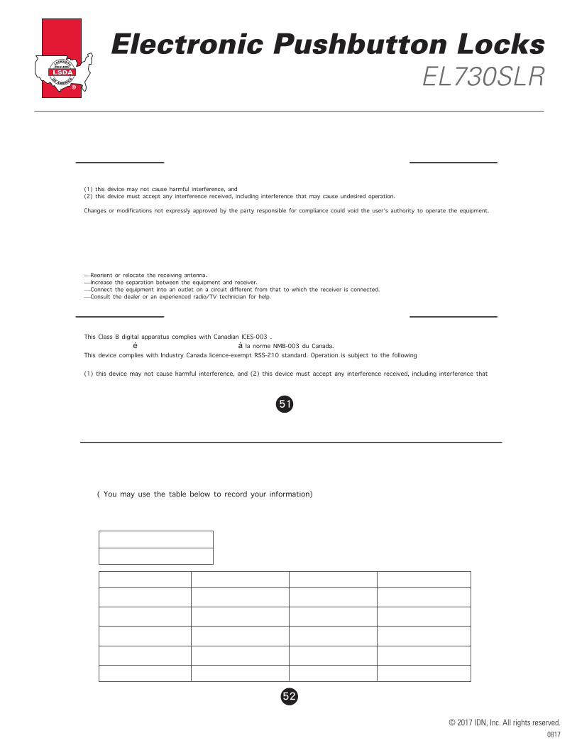
This device complies with Part 15 of the FCC. Operation is subject to the following two conditions: (1) this device may not cause harmful interference, and (2) this device must accept any interference received, including interference that may cause undesired operation.
Changes or modifications not expressly approved by the party responsible for compliance could void the user’s authority to operate the equipment.
NOTE: This equipment has been tested and found to comply with the limits for a Class B digital device, pursuant to part 15 of the FCC Rules. These limits are designed to provide reasonable protection against harmful interference in a residential installation. This equipment generates, uses and can radiate radio frequency energy and, if not installed and used in accordance with the instructions, may cause harmful interferenceto radio communications. However, there is no guarantee that interference will not occur in a particular installation. If this equipment does cause harmful interference to radio or television reception, which can be determined by turning the equipment off and on, the user isencouraged to try to correct the interference by one or more of the following measures:
—Reorient or relocate the receiving antenna.—Increase the separation between the equipment and receiver.—Connect the equipment into an outlet on a circuit different from that to which the receiver is connected.—Consult the dealer or an experienced radio/TV technician for help.
DECLARATIONS AND SAFETY STATEMENTS
IC Regulations
This Class B digital apparatus complies with Canadian ICES-003 .Cet appareil numérique de la classe B est conforme à la norme NMB-003 du Canada.This device complies with Industry Canada licence-exempt RSS-210 standard. Operation is subject to the following two conditions: (1) this device may not cause harmful interference, and (2) this device must accept any interference received, including interference that may cause undesired operation of the device.
INFORMATION PAGE
Programming code
Name User code Name User code
52
1. Do not share the programming code with anyone else.2.Keep a written copy of all vaild user codes in a safe place.( You may use the table below to record your information)3. The memory capacity for user codes is 10 sets.4. It is STRONGLY recommended changing all codes if any security information in the table is lost.
SECURITY INSTRUCTION