electronic safety and security (ess) system design and ... · (ess) system design and...
TRANSCRIPT

Electronic Safety and Security (ESS) System Design and
Implementation Best Practices
F. Patrick Mahoney CDT, RCDD Cannon Design Bob Faber RCDD/NTS MonoSystems
BICSI Draft Standard: D005

Why BICSI developed this standard
• Security equipment IP & standards based – No longer proprietary equipment & cable
– Pathways & spaces must be adequately planned to accommodate new equipment requirements
– Information technology infrastructure must be adequate to support security systems
• Standard needed to sustain design, who would you ask?

What is the Standards Development Process?
• Consensus-based Multiple interested participants include; end users, manufacturers, engineers/consultants, installers/integrators, consumer groups, testing labs, governments and research organizations.
• Industry wide Written for implementation globally.
• Voluntary Involvement is voluntary with many checks/balances.

Purpose of this standard
• For use in the design and implementation of structured cabling systems used within Electronic Safety and Security systems

Purpose of this standard
• Provides a reference of common technology & design practices
• Not intended to be used by consultants & engineers as their sole reference or as a step-by-step design guide

Purpose of this standard
• May also be used to determine design requirements in conjunction with the system owner or occupant’s security risk analysis

Purpose of this standard
• ESS system owners and operators
• Architects, Engineers and consultants
• ESS system project managers
• Authorities Having Jurisdiction
• ESS system installers
Intended primarily for, but not limited to:

Scope of this Standard
Performance specifications for ESS systems are not offered in this standard unless it relates to the structured cabling systems

Scope of this Standard
• Typical mounting heights: • Fire alarm pull station – 1200 mm (48 in) AFF
• Fire alarm horn/strobe – 2000 mm (78 in) AFF or 150 mm (6 in) below ceiling
• Intercom – 1200 mm (48 in) AFF
• Nurse call stations – 1200 mm (48 in) AFF
• Buzzers or bells – 2000 mm (78 in) AFF or 150 mm (6 in) below ceiling

Telecommunications Infrastructure Overview
• ESS systems either share the cabling system components, cabling pathways & related spaces with voice/data Information Technology (IT) networks…or…
• Use a dedicated ESS network operating in parallel with the IT network

Cabling Topology
• The topology for horizontal and backbone cabling shall be configured as a star (horizontal) or hierarchical star (backbone)

Cabling Topology
• Non-star based topologies may be used in order to accommodate other applications and associated media

Telecommunications Rooms and Telecommunications Enclosures
• Design and provisioning of the TR or TE should be in accordance with applicable standards (e.g., TIA-569-C)

Telecommunications Rooms and Telecommunications Enclosures
• Where ESS equipment is required to share space…: 1. Shall be separated from other equipment in the TR/TE
2. Shall be clearly labeled as ESS equipment
3. Shall be climate controlled • ESS designer shall calculate equipment loads, temperature
and humidity levels of all equipment in the TR, TE or ER
4. Shall be designed to incorporate security measures to restrict unauthorized access
5. Shall be located as close as practicable to the center of the area served

Telecommunications Rooms and Telecommunications Enclosures
• In shared spaces, the installation of the ESS equipment and support systems shall: 1. Be dedicated to the telecommunications function and
related support facilities 2. Equipment not related to the support of the distributor
room (e.g., water pipes, HVAC ductwork) shall not be installed in, pass through, or enter the TR or TE spaces
3. Comply with the requirements of applicable codes and standards (e.g., NFPA 70) for working space around electrical service equipment
4. Be sized to accommodate planned and unplanned MACs

Telecommunications Rooms (TR) and Telecommunications Enclosures (TE)
• TEs are typically intended to serve a portion of a floor in a building
Telecommunications Rooms and Telecommunications Enclosures
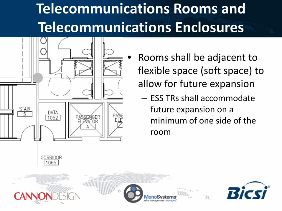
• Rooms shall be adjacent to flexible space (soft space) to allow for future expansion – ESS TRs shall accommodate
future expansion on a minimum of one side of the room

Telecommunications Rooms and Telecommunications Enclosures
• TRs should have access to two horizontal cabling pathways on a minimum of two walls
• TR should be located on the same floor as the area served and be sized at a minimum of 14 m2 (150 ft2)
• Additional TEs may be required to accommodate ESS systems

Recognized Backbone Cabling
• Backbone cabling shall follow the applicable standards (e.g., ANSI/TIA-568-C series, ISO/IEC 11801 Ed.2)

Recognized Backbone Cabling • The following media types are recognized for use in the
backbone cabling infrastructure; • 4-pair 100-ohm balanced twisted-pair cabling (e.g., ANSI/TIA-
568-C.2, ISO/IEC 11801 Ed.2) Category 5e/Class D or higher • multi-pair 100-ohm balanced twisted-pair cabling (e.g.,
ANSI/TIA-568-C.2, ISO/IEC 11801 Ed.2) Category 3/Class C or higher
• multimode optical fiber cabling (e.g., ANSI/TIA-568-C.3, ISO/IEC 11801 Ed.2) 50 micron, OM3 or 50 micron OM4 multimode cabling recommended
• single-mode optical fiber cabling (e.g., ANSI/TIA-568-C.3, ISO/IEC 11801 Ed.2) OS1 or OS2 single-mode cabling

Recognized Backbone Cabling
• Backbone cabling installed outdoors in a campus shall follow the applicable standards (e.g., ANSI/TIA-758-A, ISO/IEC 11801 Ed.2).

Recognized Horizontal Cabling
• Horizontal cabling topology should be planned to incorporate the deployment of numerous ESS services – including, but not limited to, • security cameras,
• access control devices,
• controller panels,
and other specialty applications -- that may reside on the IT network with voice and data applications.

Recognized Horizontal Cabling • Accommodate future equipment needs…
• moving from proprietary analog-based systems to IP-based systems
• Horizontal cabling types and distances of applicable cabling standards • (e.g., ISO/IEC 11801 Ed.2, ANSI/TIA-568-C, ANSI/TIA-
862-A)

Recognized Horizontal Cabling • The following media types are recognized for use in
the horizontal cabling infrastructure: • 4-pair 100-ohm balanced twisted-pair cabling (e.g., ANSI/TIA-
568-C.2, ISO/IEC 11801 Ed.2) Category 5e/Class D or higher. It is recommended to use category 6/class E or higher cabling in new installations
• multimode optical fiber cabling (e.g., ANSI/TIA-568-C.3, ISO/IEC 11801 Ed.2) 50 micron, OM3 or 50 micron OM4 multimode cabling recommended
• single-mode optical fiber cabling (e.g., ANSI/TIA-568-C.3, ISO/IEC 11801 Ed.2) OS1 or OS2 single-mode cabling
Recognized Horizontal Cabling • Horizontal cabling
installed outdoors in a campus environment, shall follow applicable standards (e.g., ANSI/TIA-758-A, ISO/IEC 11801 Ed.2)

• Coaxial cabling may be used for analog video systems… – not recommended for new installations.
– For IP cameras utilizing a coaxial cabling system, media converters or Baluns should be used to convert the signal for transmission over a recognized cabling media

Balanced Twisted-pair Cabling Use Guidelines
• Balanced twisted-pair cabling is the preferred cabling recommendation for IP devices. • Balanced twisted-pair cabling is preferred for distances
of 100 meters or less
• One pair of a 4-pair cabling channel is typically necessary for each video signal, which leaves the spare pairs available for power distribution
• When installing balanced twisted-pair cabling, it is recommended to install Category 6/Class E or higher for powering higher current PoE or PoE Plus devices

Non-user Administered Facility Connection (i.e., Direct Attach)
• Non-user administered coverage area AKA “direct attach”
• Horizontal cabling on the device end directly attaching (or connecting) to the device through a plug-ended cable or hard-wired termination, eliminating the workstation outlet, jack and patch cord

Non-user Administered Facility Connection (i.e., Direct Attach)
• IP applications that extend outside the voice and data scope, – Circumstances that do not allow a jack-to-outlet
connection on the device end
• Building automation systems (BAS) standards (e.g., ANSI/TIA-862-A) recognize these circumstances – Allowing elimination of a workstation outlet and patch
cord at the device end, when deemed unsafe and unfeasible

Non-user Administered Facility Connection (i.e., Direct Attach)
Horizontal Cross
Connect (HC)
Horizontal Cable Maximum 90 m
(295 ft)
Coverage Area
Device Termination
Coverage Area Cable
Horizontal Connection Point
(HCP)
Equipment Cord Not
Necessary

Non-user Administered Facility Connection (i.e., Direct Attach)
• Acceptable practice in the following scenarios: • In plenum spaces where an outlet or patch cord are not rated
plenum and therefore is not feasible
• If there is no room for a workstation outlet or patch cord
• If it is not safe or secure for an exposed outlet or patch cord
• If customer deems it is not aesthetically pleasing
• If the ESS cable is enclosed in conduit and the conduit system is directly attached to the ESS equipment (e.g., IP outdoor camera)
• Refer to national and local codes for compliance

Transmission Performance Field Testing
• Two new field test methods for qualifying the installed performance of a direct attach permanent link – CONFIGURATION ONE
• Single Connector Modified Permanent Link set up for Direct Attach without consolidation point
– CONFIGURATION TWO • Single Connector Modified Permanent Link set up for Direct
Attach with consolidation point

Single Connector Modified Permanent Link set up for Direct Attach without consolidation point
CONFIGURATION ONE
PERMANENT LINK ADAPTER
CHANNEL ADAPTER

Single Connector Modified Permanent Link set up for Direct Attach with consolidation point
OPTIONAL CONNECTIVITY CONFIGURATION TWO
PERMANENT LINK ADAPTER
CHANNEL ADAPTER

Thank You