elétrica de veículos com roda - parte i
DESCRIPTION
Parte 1 (de 2) do manual da Marinha Americana que trata da parte elétrica de seus veículos.TRANSCRIPT
United States Army Combined Arms Support Command
WHEELED VEHICLE ELECTRICAL SYSTEMS
(PART I)
SUBCOURSE NO. OD1002
US Army Ordnance Center and School
Aberdeen Proving Ground, Maryland
Five Credit Hours
GENERAL
The Wheeled Vehicle Electrical System (Part I) Subcourse, part of the Light Wheel VehicleMechanic MOS 63B Skill Level 3 course, is designed to teach the knowledge necessary forperforming tasks related to maintenance and repair of wheeled vehicle electrical systems.Information is provided on the fundamentals of automotive electrical systems, to include circuits,batteries, and the fundamentals and use of electrical test equipment. This subcourse is presented inthree lessons, each lesson corresponding to a terminal objective as indicated below.
Lesson 1: INTRODUCTION TO AUTOMOTIVE ELECTRICITY
TASK: Describe the fundamentals of alternating current (AC) and direct current (DC) electricityas applied to automotive equipment.
CONDITIONS: Given information on the history and theory of electricity; characteristics ofconductors and insulators; current, voltage, and resistance and their relationship; AC and DC;magnetism and induction; electrical symbols and circuits; and common circuit defects.
STANDARDS: Answer 70 percent of the multiple-choice items covering introduction toautomotive electricity.
i

Lesson 2: AUTOMOTIVE BATTERIES
TASK: Describe the construction, operation, and maintenance of automotive batteries.
CONDITIONS: Given information on the construction, operation, and rating of batteries;methods of connection; and maintenance procedures.
STANDARDS: Answer 70 percent of the multiple-choice items covering automotive batteries.
Lesson 3: FUNDAMENTALS OF ELECTRICAL TEST EQUIPMENT
TASK: Describe the purpose, construction, and operation of electrical test equipment.
CONDITIONS: Given information on voltmeters, ammeters, and ohmmeters; low-voltage circuittesters; multimeters; and simplified test equipment for internal combustion engines (STE/ICE).
STANDARDS: Answer 70 percent of the multiple-choice items covering electrical test equipment.
ii
TABLE OF CONTENTS
Section Page
TITLE PAGE.......................................................................................................................................i
TABLE OF CONTENTS....................................................................................................................iii
ADMINISTRATIVE INSTRUCTIONS..............................................................................................v
GRADING AND CERTIFICATION INSTRUCTIONS.....................................................................v
INTRODUCTION TO WHEELED VEHICLE ELECTRICAL SYSTEMS......................................vi
Lesson 1: INTRODUCTION TO AUTOMOTIVE ELECTRICITY
Learning Event 1: Describe Principles of Electricity and Magnetism.................................1
Learning Event 2: Describe Fundamentals of Electrical Circuits and Symbols................17
Practice Exercise...................................................................................................................29
Answers to Practice Exercise................................................................................................30
Lesson 2: AUTOMOTIVE BATTERIES
Learning Event 1: Describe Fundamentals of Automotive Batteries................................31
Learning Event 2: Describe Maintenance Procedures for Automotive Batteries..............48
Practice Exercise...................................................................................................................61
Answers to Practice Exercise................................................................................................62
Lesson 3: FUNDAMENTALS OF ELECTRICAL TEST EQUIPMENT
Learning Event 1: Describe Principles of Meters..............................................................63
Learning Event 2: Describe Construction and Use of Low-Voltage Circuit Testers........79
iii
Section Page
Learning Event 3: Describe Construction and Use of Multimeters..................................84
Learning Event 4: Describe Construction and Use of Simplified TestEquipment/Internal Combustion Engine (STE/ICE)...........................................................87
Practice Exercise.................................................................................................................118
Answers to Practice Exercise..............................................................................................120
EXAMINATION.............................................................................................................................121
iv
ADMINISTRATIVE INSTRUCTIONS
SUBCOURSE CONTENT
This subcourse contains three lessons, each related to wheeled vehicle electrical systems. Anintroduction presents an overall view of the subject. Each lesson then covers a specific topicpertaining to wheeled vehicle electrical systems. Each lesson is followed by a practice exercise. Anexamination covering the three lessons is provided at the end of the subcourse.
Supplementary Requirements
Materials Needed. You will need a No. 2 pencil and paper to complete this subcourse.
Supervisory Assistance. There are no supervisory requirements for completion of this subcourse.
References. No supplementary references are needed for this subcourse.
GRADING ANDCERTIFICATION INSTRUCTIONS
INSTRUCTIONS TO THE STUDENT
This subcourse has an examination that consists of 20 multiple-choice test items covering threelessons. You must score a minimum of 75% percent on this test to meet the objective of thesubcourse. Answer all questions on the enclosed ACCP examination response sheet. Aftercompleting the examination, place the answer sheet in the self-addressed envelope provided andmail it to the Institute for Professional Development (IPD) for scoring. IPD will send you a copy ofyour score.
Five credit hours will be awarded for successful completion of this subcourse.
v
INTRODUCTION TO WHEELED VEHICLE ELECTRICAL SYSTEMS
The electrical systems of military wheeled vehicles are well designed and constructed. With fewexceptions, they are much like the systems used on civilian-type vehicles. The biggest difference isthat 24-volt systems are used on military vehicles and 6- or 12-volt systems on civilian types. Also,the electrical systems on most military vehicles are waterproof.
Although these systems are well made, they still give some trouble, and they are systems that mostwheeled vehicle repairers understand the least.
One of your jobs is the maintenance of these systems. While this is not difficult, it does take some"know-how."
This subcourse will familiarize you with these systems and will provide you with the "know-how"you need.
vi

Lesson 1/Learning Event 1
LESSON 1
INTRODUCTION TO AUTOMOTIVE ELECTRICITY
TASK
Describe the fundamentals of AC and DC electricity as applied to automotive equipment.
CONDITIONS
Given information on the history and theory of electricity; characteristics of conductors andinsulators; current, voltage, and resistance and their relationship; AC and DC; magnetism andinduction; electrical symbols and circuits; and common circuit defects.
STANDARDS
Answer 70 percent of the multiple-choice items covering introduction to automotive electricity.
REFERENCES
TM9-8000
Learning Event 1:DESCRIBE PRINCIPLES OF ELECTRICITY AND MAGNETISM
INTRODUCTION
During the past 100 years, electricity became more important to man as each year went by. Today,in our homes, we depend on it for light, heat, and music. It provides power to operate waterpumps, tools, kitchen appliances, and many other household items. Outside of the home, we alsodepend on electricity for many things. The family car is a good example. It uses electricity forlights, music, heat, and to make the engine run.
1
Lesson 1/Learning Event 1
Most of the time we simply flip a switch to make electricity work for us. In a house, you use aswitch to turn the lights or radio on. You do the same thing in your car. If the electricity does notdo the work it is supposed to do when you move the switch, you usually need to get help from arepairer.
You, as a wheeled vehicle mechanic, are the repairer who will be called upon when the electricalsystems of Army vehicles do not work. You will need to find out what is wrong, first, and thencorrect the trouble.
Each of us realizes how much we depend on electricity in our day-to-day activity. Without it, therewould be no electric lights, heat, refrigeration, and so forth.
The military vehicles you will be working on must have electricity for many purposes such asignition, lights, blower fans, and so forth.
Therefore, it is easy to see that a wheeled vehicle mechanic must have a working knowledge ofelectrical circuits to keep the equipment in good operating condition.
To do your job, you will have to know what electricity is, how it is used, and how electrical itemswork. This lesson will give you the information to understand what electricity is and how it can bemade to do work for us.
COMMON KNOWLEDGE OF ELECTRICITY
To begin with, let's review some of the things commonly known about electricity.
Normally, closing a switch is all it takes to make it work.
It is available from several sources, such as flashlight batteries, storage batteries like the ones usedin cars, and generators ranging from hydroelectric plants to car generators.
We know electricity can cause a shocking sensation if it touches our bodies. We also know that, asthe amount of electricity increases, the shock we feel gets worse.
It can do work. Today, it is one of our most important sources of energy.
We also know that wires or other connections are needed between the source of electricity and theappliance to be operated.
2
Lesson 1/Learning Event 1
SCOPE OF THIS LESSON
The complete study of electricity is a wide and complicated field. Even now, a lot of questions areunanswered and there is still a lot to learn. This lesson is not designed to teach you all there is toknow about the subject. The information in this lesson will enable you to understand automotiveelectricity so that you know what it is, what it is supposed to do, how it does it, and how todetermine what is wrong if there is trouble.
HISTORICAL MILESTONES
The word "electricity" comes from the Greek word "elektron" which means amber. More than2,500 years ago, Thales, a famous Greek, found out that electricity existed. Thales noticed thatafter he rubbed a piece of amber with a woolen cloth, the amber would attract lightweight itemslike dust, straws, feathers, and lint. This was because the amber had become electrically charged.Thales knew nothing about electricity, so he thought that this happened only with amber.
In 1733, a French scientist named Dufay found out that if a piece of glass was rubbed with cat'sfur, the glass and the cat fur would become charged or electrified. He also found out that thecharged glass would attract certain things that the fur would repel or push away. From thisexperiment, he correctly decided there were two kinds of electricity that were directly opposite.
Benjamin Franklin decided the two kinds of electricity should be named POSITIVE andNEGATIVE. They are also commonly referred to as plus and minus and are shown as (+) and (-)."Positive," "plus," and "+" refer to one kind of electrical charge; "negative," "minus," and "-" referto the opposite charge.
Like charges repel each other, and unlike charges attract. Thus, if we have two items that havepositive charges, they will repel or push away from each other. The same action occurs if the itemshave negative charges. On the other hand, if we have one item with a positive charge and anotheritem with a negative charge, they will attract or pull together.
For many years it was believed that only such things as glass, amber, silk, and cat's fur could beelectrified or charged. We know now, however, that under certain conditions all substances can beelectrified.
3
Lesson 1/Learning Event 1
MATTER AND THE ATOM
The mystery of electrification and the positive and negative charges was finally solved by studyingthe construction of matter. "Matter" is any substance that has weight and occupies space.Examples of matter are the air we breathe, water, cars, clothing, and so forth. To give you an ideaof what electricity really is, so that you will be able to predict its action in automotive electricalcircuits, we need to take a brief look at the construction of matter.
Imagine that you could take some form of matter, such as a rock, and break it down into thesmallest particles that it can exist in and still be the original substance that you started with. Thesetiny particles are known as molecules.
Actually, you would not be able to do this, for as you continued to crush the rock you would finallyend up with particles of dust, and just one of the small dust particles would contain thousands ofmolecules.
Scientists have discovered that any molecule contains one or more building blocks known as atoms.Each atom is an element. There are about 100 different kinds of atoms or elements. Some aremetal, such as copper, iron, and gold. Others are nonmetallic, such as oxygen, hydrogen, andsulfur. While an element by itself is matter, different kinds of matter are formed by mixingelements. When two or more elements are mixed, we get matter that is known as a compound.For instance, a molecule of water is formed when two hydrogen atoms are joined with one oxygenatom. Therefore, water is a compound.
The secret of electrification was not discovered until scientists finally discovered that atoms aremade up of three smaller particles. These particles are electrons, protons, and neutrons. Theprotons have a positive charge, electrons have a negative charge, and neutrons are neutral (have nocharge). Figure 1 shows what we believe the atom looks like.
4
Lesson 1/Learning Event 1
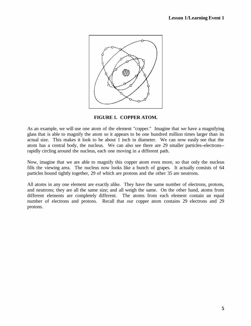
FIGURE 1. COPPER ATOM.
As an example, we will use one atom of the element "copper." Imagine that we have a magnifyingglass that is able to magnify the atom so it appears to be one hundred million times larger than itsactual size. This makes it look to be about 1 inch in diameter. We can now easily see that theatom has a central body, the nucleus. We can also see there are 29 smaller particles--electrons--rapidly circling around the nucleus, each one moving in a different path.
Now, imagine that we are able to magnify this copper atom even more, so that only the nucleusfills the viewing area. The nucleus now looks like a bunch of grapes. It actually consists of 64particles bound tightly together, 29 of which are protons and the other 35 are neutrons.
All atoms in any one element are exactly alike. They have the same number of electrons, protons,and neutrons; they are all the same size; and all weigh the same. On the other hand, atoms fromdifferent elements are completely different. The atoms from each element contain an equalnumber of electrons and protons. Recall that our copper atom contains 29 electrons and 29protons.
5
Lesson 1/Learning Event 1
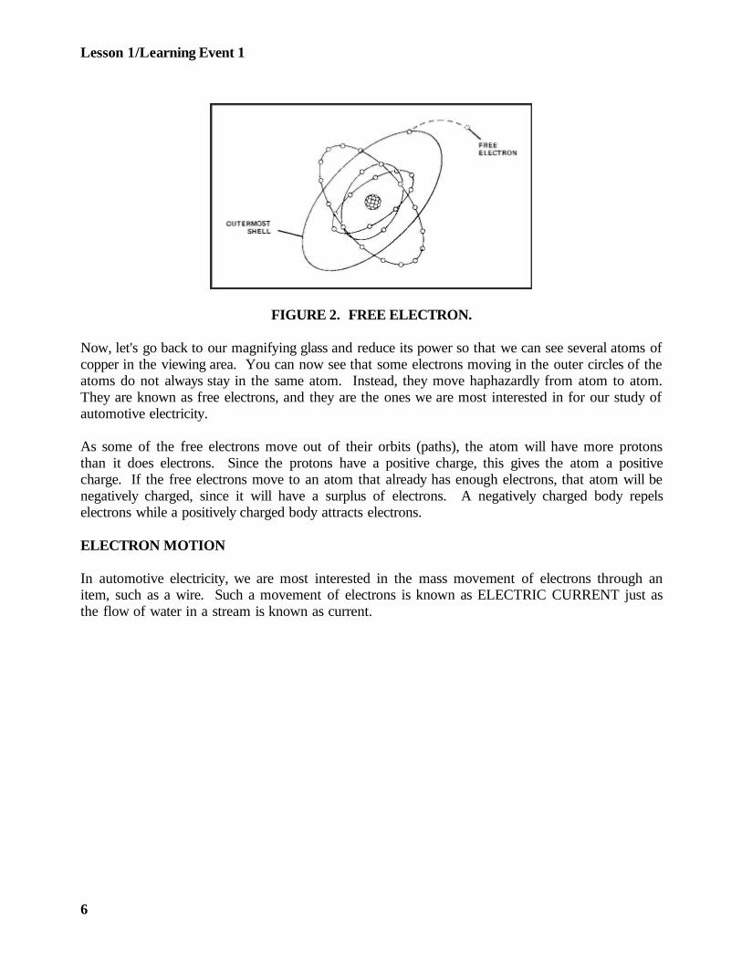
FIGURE 2. FREE ELECTRON.
Now, let's go back to our magnifying glass and reduce its power so that we can see several atoms ofcopper in the viewing area. You can now see that some electrons moving in the outer circles of theatoms do not always stay in the same atom. Instead, they move haphazardly from atom to atom.They are known as free electrons, and they are the ones we are most interested in for our study ofautomotive electricity.
As some of the free electrons move out of their orbits (paths), the atom will have more protonsthan it does electrons. Since the protons have a positive charge, this gives the atom a positivecharge. If the free electrons move to an atom that already has enough electrons, that atom will benegatively charged, since it will have a surplus of electrons. A negatively charged body repelselectrons while a positively charged body attracts electrons.
ELECTRON MOTION
In automotive electricity, we are most interested in the mass movement of electrons through anitem, such as a wire. Such a movement of electrons is known as ELECTRIC CURRENT just asthe flow of water in a stream is known as current.
6
Lesson 1/Learning Event 1
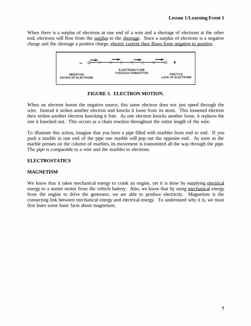
When there is a surplus of electrons at one end of a wire and a shortage of electrons at the otherend, electrons will flow from the surplus to the shortage. Since a surplus of electrons is a negativecharge and the shortage a positive charge, electric current then flows from negative to positive.
FIGURE 3. ELECTRON MOTION.
When an electron leaves the negative source, this same electron does not just speed through thewire. Instead it strikes another electron and knocks it loose from its atom. This loosened electronthen strikes another electron knocking it free. As one electron knocks another loose, it replaces theone it knocked out. This occurs as a chain reaction throughout the entire length of the wire.
To illustrate this action, imagine that you have a pipe filled with marbles from end to end. If youpush a marble in one end of the pipe one marble will pop out the opposite end. As soon as themarble presses on the column of marbles, its movement is transmitted all the way through the pipe.The pipe is comparable to a wire and the marbles to electrons.
ELECTROSTATICS
MAGNETISM
We know that it takes mechanical energy to crank an engine, yet it is done by supplying electricalenergy to a starter motor from the vehicle battery. Also, we know that by using mechanical energyfrom the engine to drive the generator, we are able to produce electricity. Magnetism is theconnecting link between mechanical energy and electrical energy. To understand why it is, we mustfirst learn some basic facts about magnetism.
7
Lesson 1/Learning Event 1
Magnetism is an invisible force that attracts iron and steel. It was first noticed in a particular typeof stone called magnetite that is a natural magnet. Magnetite was first used as a compass to telldirections for sailors on the ocean or travelers in unfamiliar country. This was possible because, ifa piece of magnetite is suspended so it is free to rotate, it will turn so it points to the earth'smagnetic north and south poles. One end always points to the north so this is called the north poleand the opposite end is called the south pole.
Pieces of magnetite, natural magnets taken from the earth, have little value now. Better magnetscan be made from iron and steel by artificial means. Magnets that are made from soft iron areknown as "temporary" magnets because they lose their magnetism quickly. Magnets made fromsteel are known as "permanent" magnets because they stay magnetized for a long time. Permanentmagnets that most of us are familiar with are the bar- and horseshoe-shaped kinds. Let's discuss afew experiments with some permanent bar magnets to gain some knowledge of the invisible forcesthey possess.
- If a bar magnet is suspended by a thread, it will swing into a north-south direction with itsends pointing to the earth's magnetic poles. Like the magnetite, the end of the magnettoward the north is known as the north pole and the end to the south the south pole.
- If we obtain a second bar magnet and move its north pole toward the north pole of thesuspended magnet we can see that the suspended magnet moves away from the secondmagnet. Likewise, if the south poles are moved close together, the suspended magnet willmove away. Therefore magnetic poles that are alike repel each other.
- Now, let's move the south pole of the second bar magnet toward the north pole of thesuspended magnet. Instead of moving away as it did before, the suspended magnet nowmoves toward the second magnet. In fact, if we allow the north and south poles of themagnets to come in contact, they stick together, and it takes considerable force to pullthem apart. This last experiment then proves that unlike magnetic poles attract eachother.
The surrounding space around a magnet that is affected by the magnet's invisible force is known asa MAGNETIC FIELD. The magnetic field is often demonstrated by sprinkling some iron filingson a piece of paper that has been placed on a tabletop. A bar magnet is then dropped into thecenter of the paper. Of course, a large number of the filings are immediately attracted and movedabout by the magnet.
8
Lesson 1/Learning Event 1
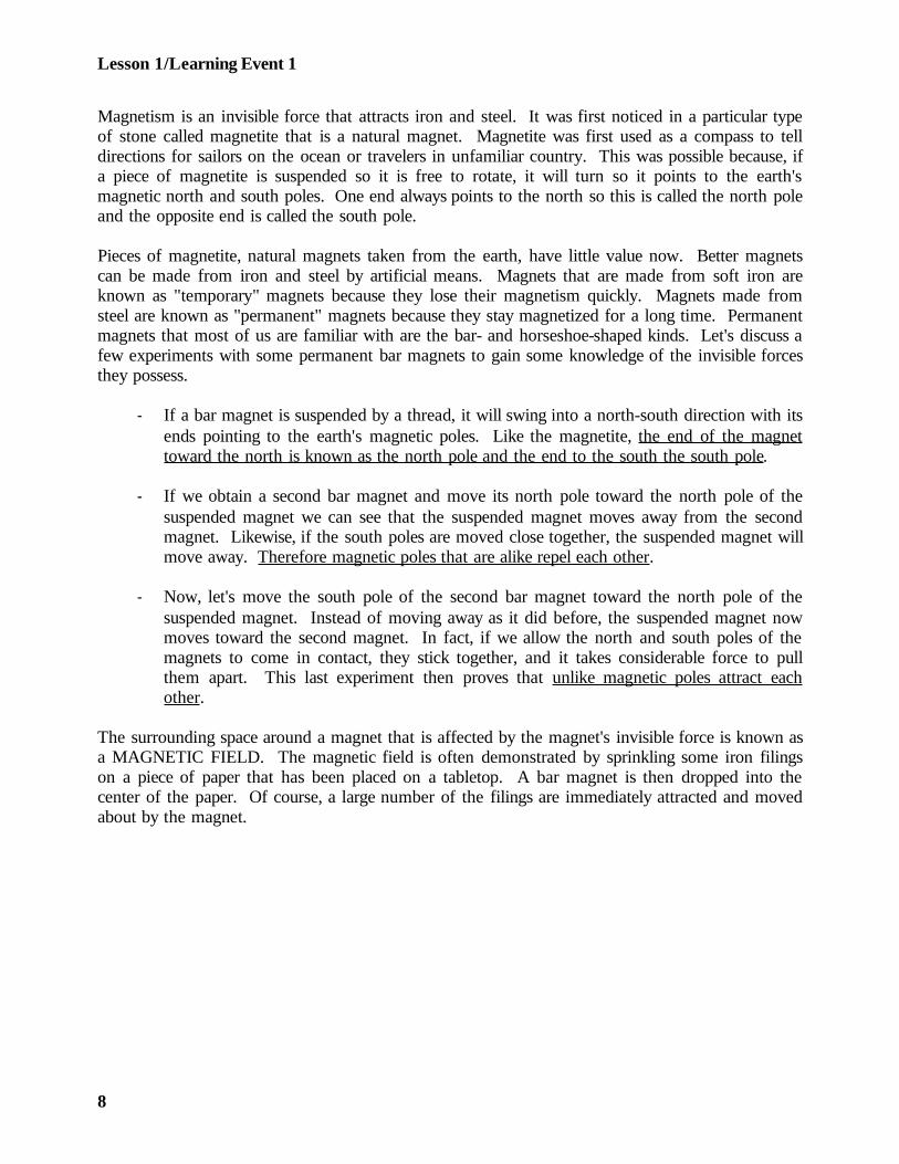
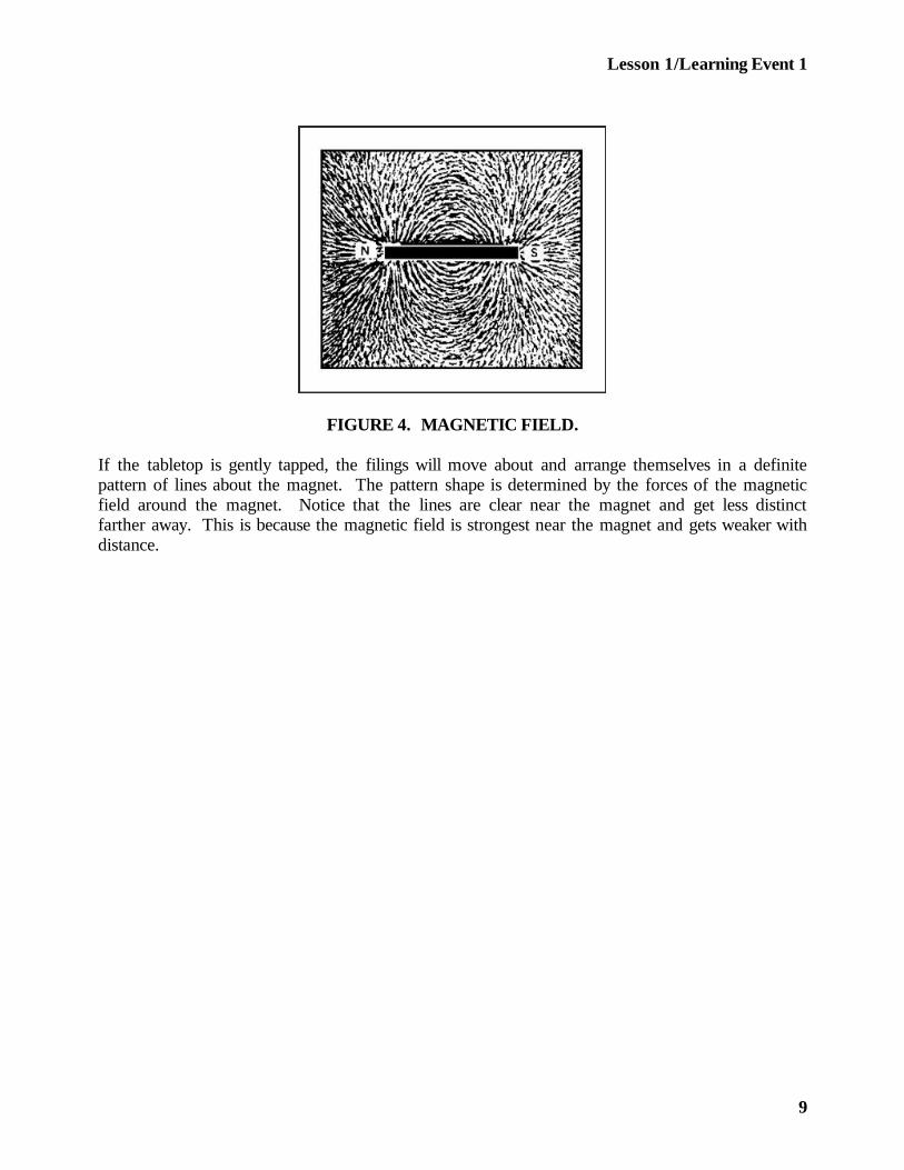
FIGURE 4. MAGNETIC FIELD.
If the tabletop is gently tapped, the filings will move about and arrange themselves in a definitepattern of lines about the magnet. The pattern shape is determined by the forces of the magneticfield around the magnet. Notice that the lines are clear near the magnet and get less distinctfarther away. This is because the magnetic field is strongest near the magnet and gets weaker withdistance.
9
Lesson 1/Learning Event 1
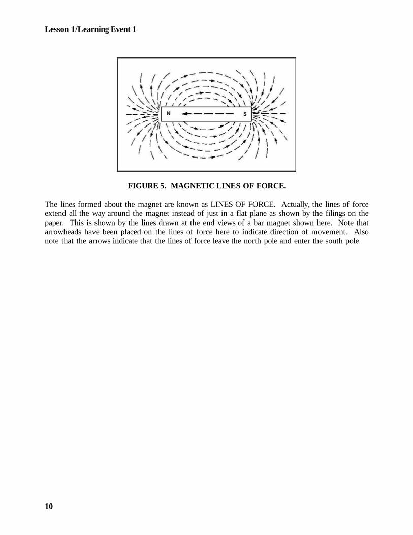
FIGURE 5. MAGNETIC LINES OF FORCE.
The lines formed about the magnet are known as LINES OF FORCE. Actually, the lines of forceextend all the way around the magnet instead of just in a flat plane as shown by the filings on thepaper. This is shown by the lines drawn at the end views of a bar magnet shown here. Note thatarrowheads have been placed on the lines of force here to indicate direction of movement. Alsonote that the arrows indicate that the lines of force leave the north pole and enter the south pole.
10
Lesson 1/Learning Event 1
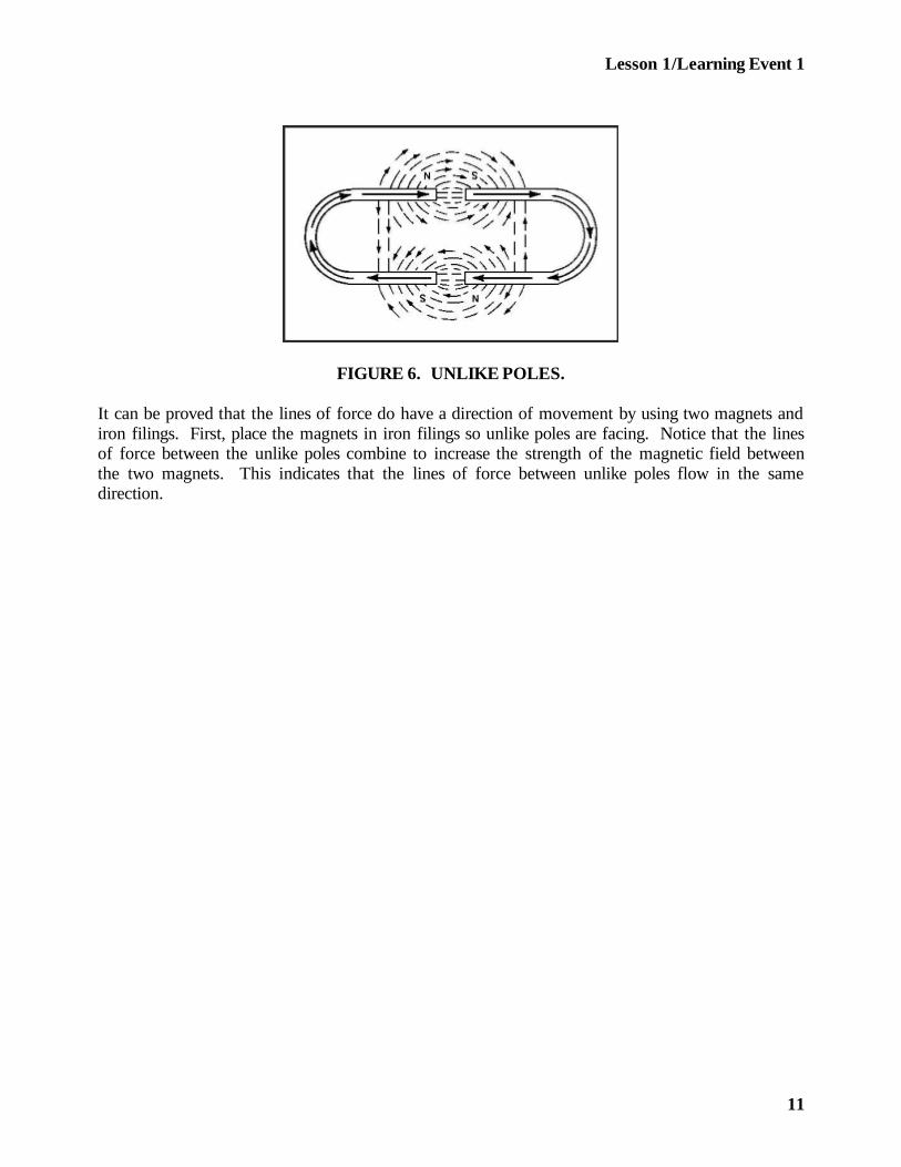
FIGURE 6. UNLIKE POLES.
It can be proved that the lines of force do have a direction of movement by using two magnets andiron filings. First, place the magnets in iron filings so unlike poles are facing. Notice that the linesof force between the unlike poles combine to increase the strength of the magnetic field betweenthe two magnets. This indicates that the lines of force between unlike poles flow in the samedirection.
11
Lesson 1/Learning Event 1
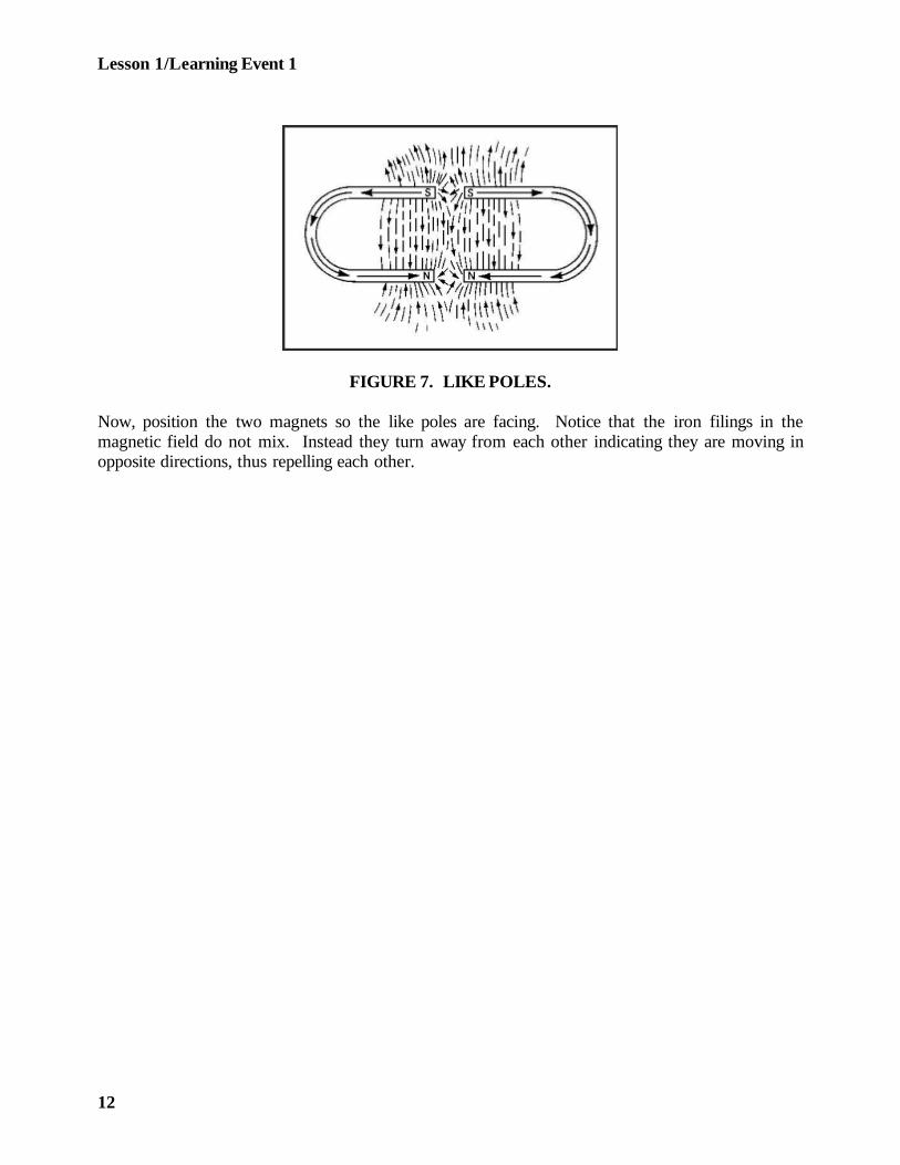
FIGURE 7. LIKE POLES.
Now, position the two magnets so the like poles are facing. Notice that the iron filings in themagnetic field do not mix. Instead they turn away from each other indicating they are moving inopposite directions, thus repelling each other.
12
Lesson 1/Learning Event 1
INDUCTION
By now you may be thinking, so what does magnetic force have to do with electricity? Well, let'sgive this matter more consideration and find out what the connection is and how it may be used.
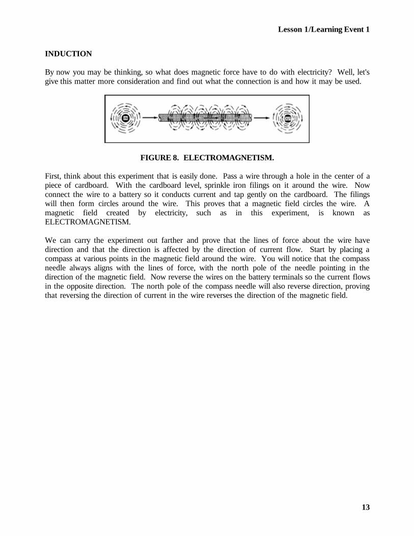
FIGURE 8. ELECTROMAGNETISM.
First, think about this experiment that is easily done. Pass a wire through a hole in the center of apiece of cardboard. With the cardboard level, sprinkle iron filings on it around the wire. Nowconnect the wire to a battery so it conducts current and tap gently on the cardboard. The filingswill then form circles around the wire. This proves that a magnetic field circles the wire. Amagnetic field created by electricity, such as in this experiment, is known asELECTROMAGNETISM.
We can carry the experiment out farther and prove that the lines of force about the wire havedirection and that the direction is affected by the direction of current flow. Start by placing acompass at various points in the magnetic field around the wire. You will notice that the compassneedle always aligns with the lines of force, with the north pole of the needle pointing in thedirection of the magnetic field. Now reverse the wires on the battery terminals so the current flowsin the opposite direction. The north pole of the compass needle will also reverse direction, provingthat reversing the direction of current in the wire reverses the direction of the magnetic field.
13
Lesson 1/Learning Event 1
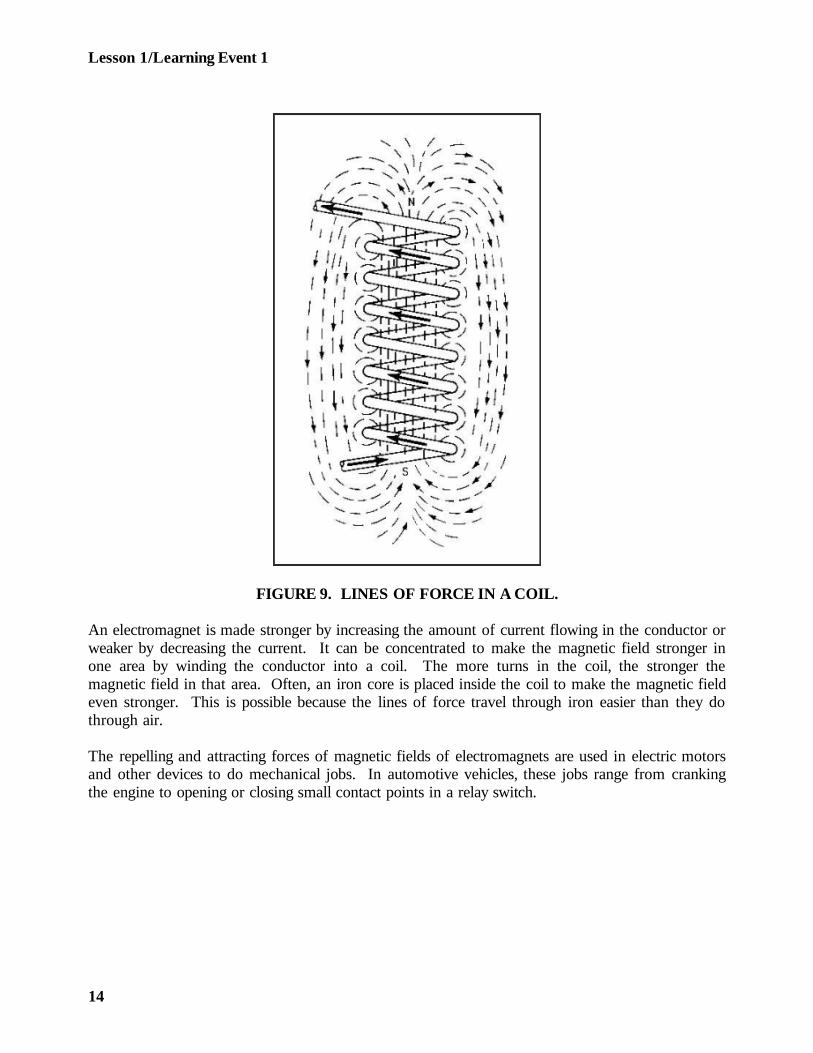
FIGURE 9. LINES OF FORCE IN A COIL.
An electromagnet is made stronger by increasing the amount of current flowing in the conductor orweaker by decreasing the current. It can be concentrated to make the magnetic field stronger inone area by winding the conductor into a coil. The more turns in the coil, the stronger themagnetic field in that area. Often, an iron core is placed inside the coil to make the magnetic fieldeven stronger. This is possible because the lines of force travel through iron easier than they dothrough air.
The repelling and attracting forces of magnetic fields of electromagnets are used in electric motorsand other devices to do mechanical jobs. In automotive vehicles, these jobs range from crankingthe engine to opening or closing small contact points in a relay switch.
14
Lesson 1/Learning Event 1
Now, let's see how mechanical force can be used in creating an electric current. Using a horseshoemagnet, a conductor (such as a copper wire), and a sensitive, current-indicating meter (such as agalvanometer), you can demonstrate this.
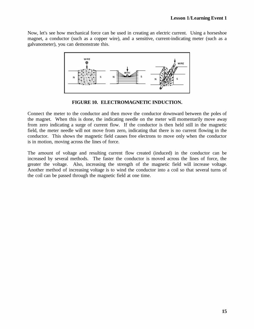
FIGURE 10. ELECTROMAGNETIC INDUCTION.
Connect the meter to the conductor and then move the conductor downward between the poles ofthe magnet. When this is done, the indicating needle on the meter will momentarily move awayfrom zero indicating a surge of current flow. If the conductor is then held still in the magneticfield, the meter needle will not move from zero, indicating that there is no current flowing in theconductor. This shows the magnetic field causes free electrons to move only when the conductoris in motion, moving across the lines of force.
The amount of voltage and resulting current flow created (induced) in the conductor can beincreased by several methods. The faster the conductor is moved across the lines of force, thegreater the voltage. Also, increasing the strength of the magnetic field will increase voltage.Another method of increasing voltage is to wind the conductor into a coil so that several turns ofthe coil can be passed through the magnetic field at one time.
15

Lesson 1/Learning Event 1
As you can see, to induce electricity in a conductor, we must have a magnetic field and motion. Inautomotive generators, mechanical energy from the engine is used to supply the motion. On sometypes of generators, the conductor is moved through a stationary magnetic field, while on others themagnetic field is moved and the conductor is stationary.
The induction principle is also used in TRANSFORMERS. A transformer is an electrical devicethat is used for stepping up or stepping down electrical voltage. The ignition coil of an automotivevehicle is actually a transformer that steps the 12- to 24-volt battery voltage up to the severalthousand volts needed to ignite the fuel mixture. In the following paragraphs, we will discuss theconstruction and operation of transformers.
A simple transformer often contains an iron core and consists of two coils of wire. One coil isactually an electromagnet and is called the primary winding. The second coil is called thesecondary winding.
If the primary winding is connected to a battery, current will flow through the winding causing amagnetic field to build up around the coil. As the field builds up, its lines of force move outwardcutting across the coils of the secondary winding. The secondary winding will have a voltageinduced in it as a result of the lines of force cutting across its coils. Now, if the ends of thesecondary winding conductor were connected into a complete circuit, current would flow until theinduced voltage dropped to zero.
When the primary winding is disconnected from the battery, the magnetic lines of force willcollapse and disappear. As this happens, the lines of force move rapidly inward toward the primarywinding. Again, the moving lines of force cut across the coils of the secondary winding inducing avoltage. This time the lines are moving in the opposite direction so the induced voltage causescurrent to flow in the opposite direction.
16
Lesson 1/Learning Event 2
Learning Event 2:DESCRIBE FUNDAMENTALS OF ELECTRICAL CIRCUITS AND SYMBOLS
CONDUCTORS
Atoms from different elements are not alike. Electrical current will flow through some materialseasily but, in others, practically no electrons will flow. If current flows through a material easily,the material is called a CONDUCTOR.
A good conductor is a material that has a large number of free electrons. All metals are conductorsof electricity, but some are better conductors than others. Examples of good conductors are silver,copper, and aluminum. Silver is a better conductor than copper, but copper is more widely usedbecause it is cheaper. Since aluminum is light, it is used as a conductor where weight is a majorconsideration.
The ability of a material to conduct electricity also depends on its size. The greater its diameterand the shorter its length, the better it conducts. Conductors may be in the forms of bars, tubes,or sheets, but the most common form is wire. Many sizes of wire are used, from the fine hair-likewire in sensitive measuring instruments to the large bar-like wire used for carrying high current inpower generating plants.
Most wire conductors that you will be working with on automotive vehicles are stranded wires. Astranded wire consists of many small wires twisted together to make one conductor. This makesthem very flexible so they can be bent and fitted around vehicle components without breaking.
INSULATORS
If a material has so few free electrons that it blocks electron flow, it is called an INSULATOR.
No material known is a perfect insulator, but some materials are such poor conductors that for allpractical purposes they are classed as insulators. Examples of insulators are porcelain, glass, air,rubber, oil, Bakelite, and certain kinds of enamel and varnish.
Insulators are used to make sure that the flow of electrons does not stray out of the path that hasbeen provided with conductors. An example of this is the insulator used to anchor overheadelectric lines to their utility poles. The insulators block the electrons to prevent them from flowinginto the pole and into the ground.
17
Lesson 1/Learning Event 2
In automotive vehicles, insulators must be used to keep the electrons or current in the proper path.Wire conductors are covered with insulating material, such as rubber, cotton, plastic, or enamel.Hard materials, such as fiberboard and Bakelite, are used in the ignition system and for switcheswhere parts need to be mounted securely by a rigid insulator.
CURRENT
Electric current, like the flow of water, can be measured. Water flowing in a pipe is measured bythe number of gallons of water that flow per minute. Electric current is measured by units knownas AMPERES. It takes more than six billion electrons moving past a given point in one second tomake up one ampere.
A device known as an AMMETER is used to measure amperes.
While 1 ampere may sound like a lot, in automotive electricity it is considered a rather smallamount of current. Some lights may require about 1 ampere, but the starter motor requires 100amperes or more.
VOLTAGE
As we said before, electron flow or current is caused by electron unbalance. In other words, whenone end of a conductor has a positive charge and the other end has a negative charge, electrons willmove to the positive end. The greater the difference in the amount of electrons at opposite ends ofa wire, the greater the pressure will be that is pushing the electrons through the wire. This pressureis commonly known as potential difference, or VOLTAGE.
Voltage and its effect on electric current in a wire can be compared to pressure and its effect onwater flowing in a pipe. When pressure is increased on water in a pipe, a greater volume of waterwill flow in a given period. If the voltage of an electrical circuit is increased, a greater number ofelectrons will move--more current will flow.
Voltage is measured with a VOLTMETER, which will be covered in detail later.
18

Lesson 1/Learning Event 2
RESISTANCE
When the voltage forces the current to flow in a wire, the electrons meet RESISTANCE.Resistance is caused by the friction of the electrons bumping into the atoms. If you rub yourfingertips across a table, the friction causes heat. As you move your fingertips faster, the heatbecomes greater. Likewise, electrons flowing through a wire cause heat. If the voltage is increased,current flow and the amount of heat are also increased. If the current flow is increased enough,the wire will become hot enough to literally burn up.
The heating action of current flow is one of the great uses of electricity. For an example, let's takea look at a light bulb.
The bulb contains a filament made of a material that has a lot of resistance to current flow and canwithstand extreme heat. The filament ends are connected to two contacts at the base of the bulb.(Usually the metal part of the base serves as one contact.) The filament is then enclosed in glass,and most of the air is removed, because if air gets to the filament, it will burn up too easily.
Voltage from a battery or other source is applied to the two contacts at the base of the bulb.Current then flows through the filament causing it to get white-hot which produces light.
For the bulb to function properly the material in the filament, the size of the filament, and theamount of voltage supplied must be carefully balanced so just the correct amount of current willflow. If the current flow is too small, the filament will not get heated enough and the bulb will notglow brightly. If the current flow is too great, the filament will burn up.
Sometimes a special part known as a RESISTOR is placed in the electrical circuit to reduce thecurrent flow. The action of the resistor can be compared to the restricting action of a water valveor faucet. Opening the valve more will cause more water to flow because there will be lessresistance to the flow of water. Likewise, reducing the resistance in an electrical circuit will causemore electrical current to flow.
Resistors are usually made from carbon or special wire. Some resistors are "fixed"; that is, they aremade so you cannot change the resistance as you can with the faucet in a water system. Resistorsthat you can adjust are known as "variable" resistors or RHEOSTATS. A rheostat usually has amovable contact that you can move along the length of a resistor. By moving the contact, youchange the effective length of the resistor. The greater the distance the current travels to getthrough the resistor, the greater the resistance of the rheostat.
19
Lesson 1/Learning Event 2
The amount of resistance that a resistor or any other conductor offers to current flow is measuredin OHMS. A material has 1 ohm of resistance when 1 volt (pressure) will force 1 ampere ofcurrent to flow through it. Resistance is measured with an OHMMETER, which will be coveredlater.
RELATIONSHIP OF QUANTITIES IN AN ELECTRICAL CIRCUIT
There is a definite relationship between voltage, resistance, and amperage that must be consideredwhen maintaining automotive electrical systems. From the example of the light bulb, you can seethat whether or not the bulb works as it should depends on the amount of current that is flowingthrough the circuit. From our study up to now, you can also see that a change in either theamount of voltage or the amount of resistance will change the amount of current flowing in acircuit. Here are some facts about changes in voltage, resistance, and amperage that you shouldremember.
If the voltage in a circuit is made higher and the resistance remains the same, the amperage(current) will also get higher. The reverse of this is also true--less voltage will cause less amperage.
If more resistance is put in an electrical circuit, the current is reduced whereas less resistance allowsmore current to flow.
Resistance can be changed by changing the length or diameter of a wire, by using a rheostat, or byusing different sizes of fixed resistors.
ALTERNATING CURRENT
The electricity that comes to your home for operating the lights, refrigerators, and so forth, isALTERNATING CURRENT (AC). It was given this name because the electrons move throughthe wire first in one direction and then in the opposite direction. Since current flows from negative(surplus of electrons) to positive (shortage of electrons), the generating plant producing analternating current must be periodically changing the electrical charge. In this manner, the electronsare caused to move back and forth in the circuit instead of in a constant stream moving in onedirection only.
20
Lesson 1/Learning Event 2
This can be illustrated if we compare AC to the swinging pendulum of a clock. Current, like thependulum, starts from one extreme point to the right or left and very slowly builds up to fastestspeed at about one-half of its travel. Then, its speed begins to fall off until it comes to a completestop for just an instant before swinging again in the opposite direction. AC is defined as a currentthat is constantly building up or falling off and periodically changing direction.
When the electron flow returns to the same point it started from, just as the pendulum completesits swing to and fro, this completes one cycle. The number of cycles that occur each second isknown as the frequency of the current. The current supplied to your home, in this country, has afrequency of 60 cycles per second. Lately, the term "Hertz" is often used instead of cycles. Soremember that both "60-Hertz AC" and "60-cycle AC" mean the same thing.
DIRECT CURRENT
Electric current that flows in one direction only is called DIRECT CURRENT. The term directcurrent is commonly shortened to DC. Batteries cannot reverse the electrical charge, as must bedone to produce AC, so they always supply DC. Since automotive vehicles use batteries, mostelectrical circuits that you will be working on use DC.
In automotive electricity, we are sometimes faced with the problem of changing AC to DC. Forinstance, if the vehicle is equipped with an AC generator, that current cannot be used to charge thevehicle battery. In this case, the AC must be changed to DC.
Parts called RECTIFIERS or diodes are used to change AC to DC. A rectifier works like a one-way check valve in a water system. Water or current can flow through the check valve or rectifierin one direction, but flow is blocked in the opposite direction. Rectifiers are made from materialsthat are constructed in such a manner that the atoms allow electrons to move in one direction butnot the other.
21
Lesson 1/Learning Event 2
SYMBOLS
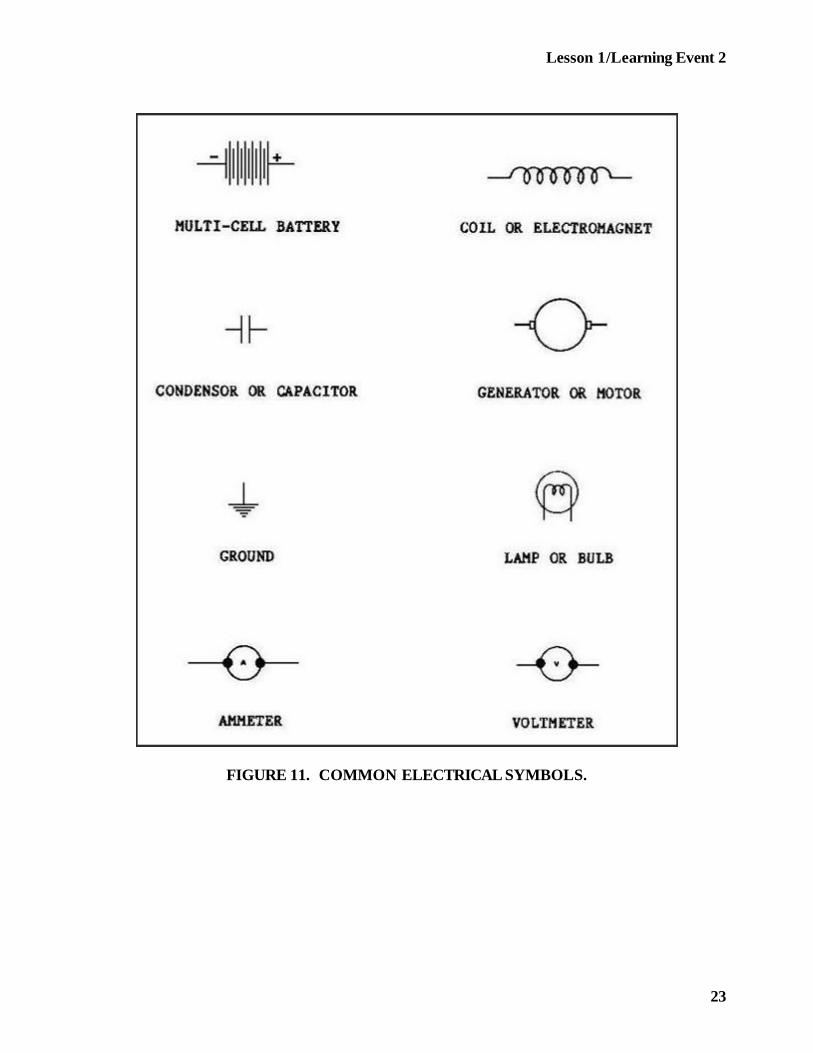
Automotive repair manuals use several methods to present all the information that you need torepair electrical systems. For instance, some of the information is presented through written words,but a lot is presented through drawings and the use of SYMBOLS. A symbol is a sign or figurethat stands for something else. Symbols are especially useful in electricity, since they can be usedto show many things that are actually invisible.
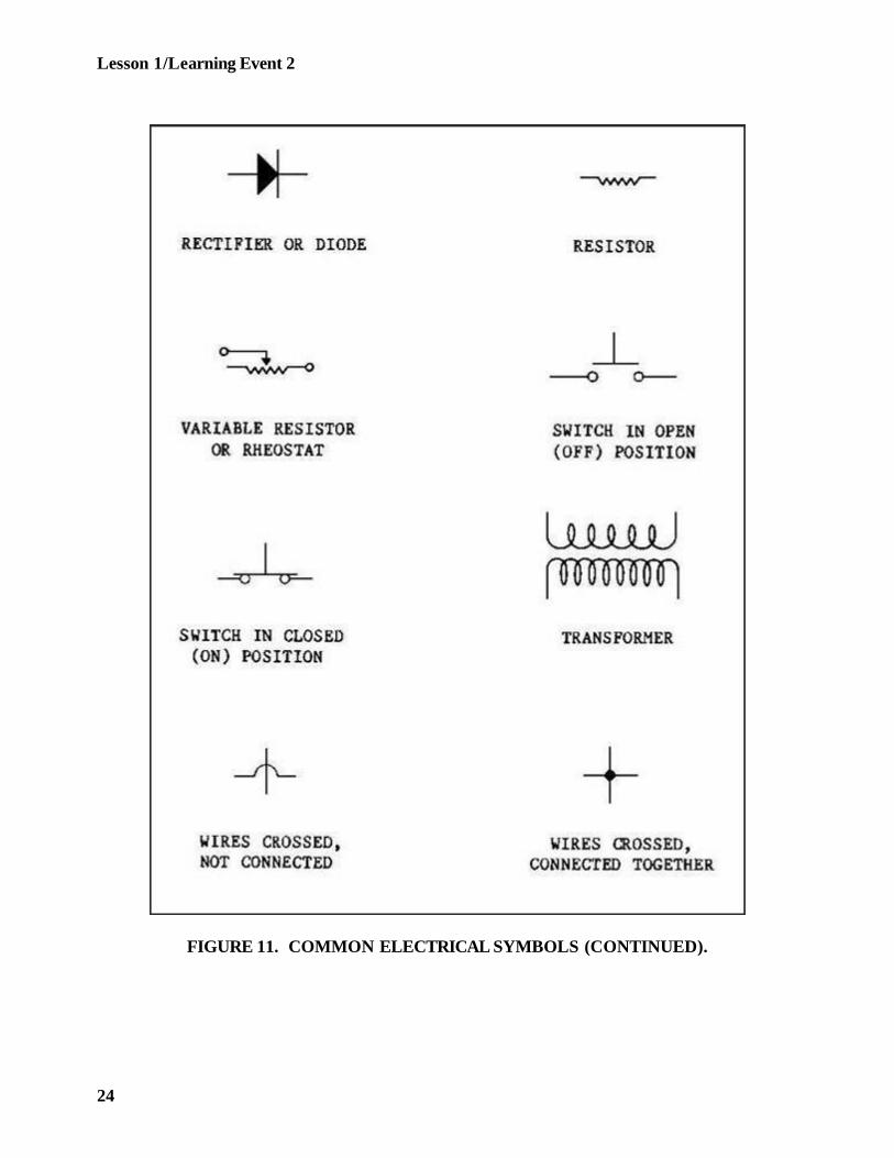
Before you can read and obtain the needed information from electrical drawings (schematicdiagrams), you must know the meaning of the symbols that are used. Let's take a look at somecommon symbols that are used in schematic diagrams of an automotive electrical circuit.
22
Lesson 1/Learning Event 2
FIGURE 11. COMMON ELECTRICAL SYMBOLS.
23
Lesson 1/Learning Event 2
FIGURE 11. COMMON ELECTRICAL SYMBOLS (CONTINUED).
24
Lesson 1/Learning Event 2
TYPES OF CIRCUITS
Electrical circuits can be laid out in series, parallel, or series-parallel. To troubleshoot an electricalcircuit, you must be able to identify the way it is laid out and understand how current flows in thecircuit.
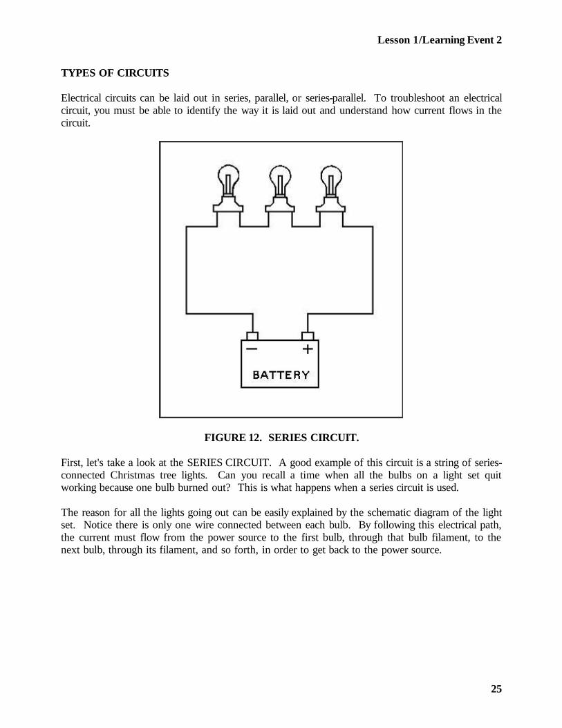
FIGURE 12. SERIES CIRCUIT.
First, let's take a look at the SERIES CIRCUIT. A good example of this circuit is a string of series-connected Christmas tree lights. Can you recall a time when all the bulbs on a light set quitworking because one bulb burned out? This is what happens when a series circuit is used.
The reason for all the lights going out can be easily explained by the schematic diagram of the lightset. Notice there is only one wire connected between each bulb. By following this electrical path,the current must flow from the power source to the first bulb, through that bulb filament, to thenext bulb, through its filament, and so forth, in order to get back to the power source.
25
Lesson 1/Learning Event 2
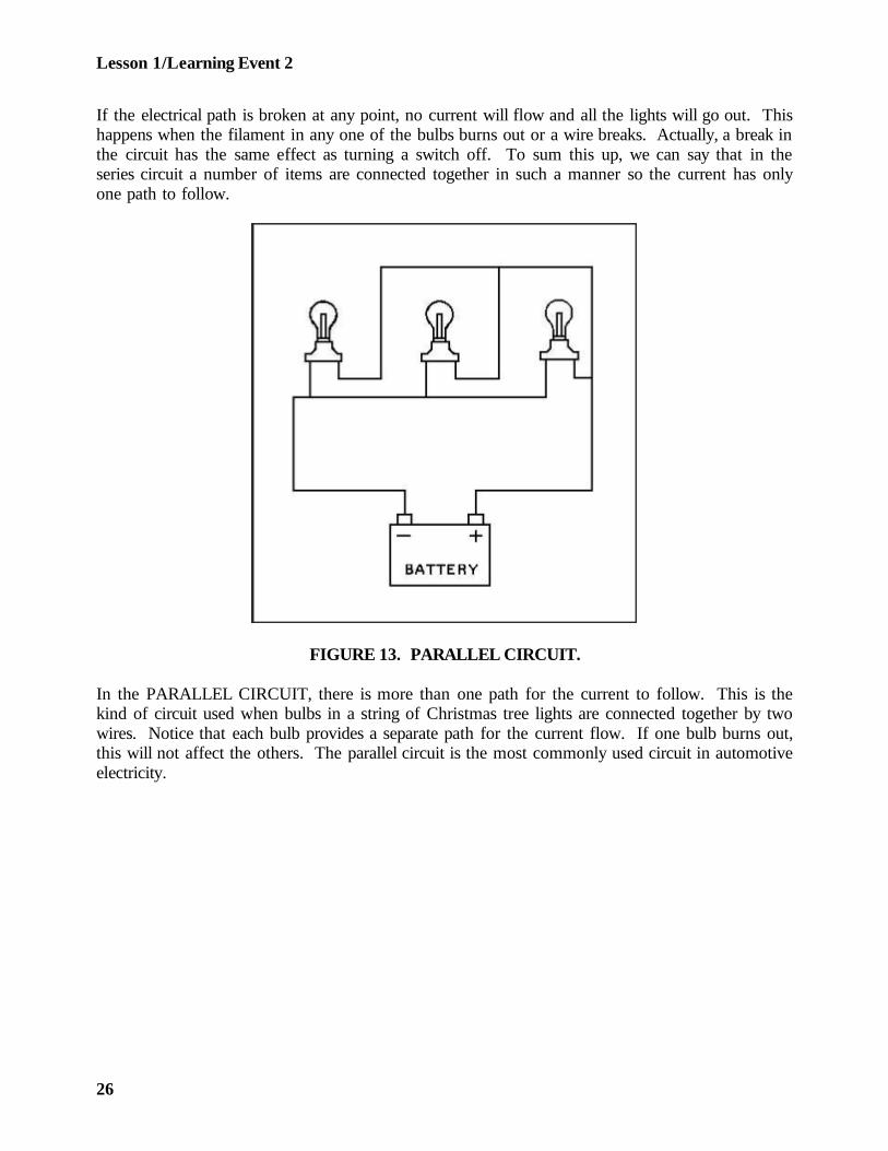
If the electrical path is broken at any point, no current will flow and all the lights will go out. Thishappens when the filament in any one of the bulbs burns out or a wire breaks. Actually, a break inthe circuit has the same effect as turning a switch off. To sum this up, we can say that in theseries circuit a number of items are connected together in such a manner so the current has onlyone path to follow.
FIGURE 13. PARALLEL CIRCUIT.
In the PARALLEL CIRCUIT, there is more than one path for the current to follow. This is thekind of circuit used when bulbs in a string of Christmas tree lights are connected together by twowires. Notice that each bulb provides a separate path for the current flow. If one bulb burns out,this will not affect the others. The parallel circuit is the most commonly used circuit in automotiveelectricity.
26

Lesson 1/Learning Event 2
FIGURE 14. SERIES-PARALLEL CIRCUIT.
The SERIES-PARALLEL circuit is a combined series and parallel circuit. This is illustrated by thethree-bulb circuit here. All the current flowing in the circuit must go through bulb 1. There is onlyone path here so this is the series part of the circuit. But, on the other side of bulb 1, the electricalpath divides. There, part of the current flows through bulb 2 and the remainder through bulb 3.Then, the paths join again to form a single path to the power source. The divided paths throughbulbs 2 and 3 are the parallel part of the circuit.
ELECTRICAL CIRCUIT DEFECTS
Circuits are also described as being grounded, shorted, or open or as having a high-resistanceconnection. These terms refer to conditions that exist in a circuit and usually describe a defect.Let's go into these terms in more detail so you will grasp the full meaning of each.
A GROUNDED circuit exists when defective insulation allows a conductor, such as a wire, to touchthe vehicle frame. This probably causes most of the electrical fires on automotive vehicles.
27
Lesson 1/Learning Event 2
In automotive circuits only one insulated wire to the battery is used. One battery terminal, usuallythe negative, is connected to the vehicle frame by a ground cable, and the frame serves as oneconductor. When the switch is closed, current flows from the negative terminal of the battery,through the frame to the bulb, then through an insulated wire, light switch, and to the positiveterminal of the battery.
Now, let's imagine that the insulation wears off exposing a bare spot on the wire between the lightswitch and the bulb. Let us further imagine that the exposed wire touches the frame. Batterycurrent can now flow from the frame to the touching wire, through the switch, and back to thebattery. Before, the high resistance of the bulb prevented a large amount of current from flowing.With the wire grounded on the frame, current can bypass the bulb, and the circuit now has verylittle resistance. As a result, so much current will flow through the wire that it will get hot enoughto melt and can set fire to any nearby flammable objects.
A SHORT CIRCUIT occurs when two exposed wires touch. This will let the current flow in thecircuits for both wires even though the switch is closed in only one circuit. You can realize theresults of this defect if you will imagine that a car has a short circuit between the wires to the tailand stoplights. When the taillight switch is turned on, battery current from the frame divides andflows through both lights and then joins to form one path at the short circuit. So both lights areburning even though the stoplight should not be.
When an OPEN CIRCUIT exists, no current flows. For example, a light circuit is open when itsswitch is off or open, when a wire conductor is broken, or when the bulb filament is burned out.An open circuit occurs in a circuit that is good when you turn off the switch. The other conditionsare defects in a bad circuit.
A HIGH-RESISTANCE CONNECTION is usually the result of corrosion at a battery post, loosewires at any terminal, or frayed wires. (A frayed wire has some but not all of the strands of wirebroken.) A high-resistance connection reduces the amount of current flowing so the circuit cannotwork as it should. In a light circuit, for instance, the bulb filament would not glow as brightly as itshould.
28
Lesson 1
PRACTICE EXERCISE
1. The nucleus of an atom contains particles with
a. negative and positive charges.b. positive and neutral charges.c. neutral and negative charges.
2. A material that contains many free electrons is called
a. a compound.b. a conductor.c. an insulator.
3. Which of the following does not affect the strength of an electromagnet?
a. The amount of current flowb. The number of turns in the coilc. The direction of current flow
4. Which defect will prevent current flow?
a. Short circuitb. Groundc. Open circuit
5. The current in a circuit can be reduced by increasing the
a. resistance.b. applied voltage.c. diameter of the conductor.
29
Lesson 1
ANSWERS TO PRACTICE EXERCISE
1. b (page 4)
2. b (page 17)
3. c (page 14)
4. c (page 28)
5. a (page 20)
30
Lesson 2/Learning Event 1
LESSON 2
AUTOMOTIVE BATTERIES
TASK
Describe the construction, operation, and maintenance of automotive batteries.
CONDITIONS
Given information on the construction, operation, and rating of batteries; methods of connection;and maintenance procedures.
STANDARDS
Answer 70 percent of the multiple-choice items covering automotive batteries.
REFERENCES
TM9-8000
Learning Event 1:DESCRIBE FUNDAMENTALS OF AUTOMOTIVE BATTERIES
INTRODUCTION
In the first lesson you learned that electricity can be produced magnetically. Electricity is alsoproduced chemically by means of a battery.
Batteries used in automotive vehicles supply electricity for cranking the engine, igniting the fuelmixture in the cylinders, and operating most accessories. In fact, cars as they are now designedcould not operate without batteries. Understanding the batteries and knowing how to keep them ingood condition are vital parts of good automotive maintenance. Present-day cars would be quitehelpless and of no use without the electricity furnished by a good battery that is properly connected.
31
Lesson 2/Learning Event 1
We, as mechanics, must know a great deal about batteries to keep them in good working order.Automotive batteries need daily attention from the operator plus some frequent maintenanceperformed by the operator and the mechanic, as well as special attention under certain conditions.To do your part, you will need knowledge of batteries and the procedures involved in theirmaintenance.
A battery is nothing more than two unlike conductors immersed in a special solution calledelectrolyte.
You can make a battery in a few minutes if you have a lemon, a paper clip, and a piece ofuninsulated copper wire. Here is how it is done:
- Straighten out the paper clip and cut the copper wire so it is the same length as the paperclip. Stick both the clip and the wire deep into the lemon so they are close together but nottouching. Now, if you touch the free ends of the wire and paper clip to your tongue, youwill experience a slight tingle and a metallic taste.
- The tingle and the metallic taste are due to electrons passing through the saliva on yourtongue. The lemon juice is the electrolyte solution; the steel paper clip and the copper wireare the two unlike conductors. Action of acid in the juice combining with the conductorscauses an excess of electrons to build up on one conductor. When you touched yourtongue to the conductors, you closed the circuit and electrons began to flow.
Almost everyone is familiar with the common flashlight battery (dry-cell battery).
The battery consists of a zinc cup-like container that is sealed at the top. A carbon rod is set in themiddle of, and insulated from, the container. The rod extends out the top with its exposed tipcovered by a metal cap. The cup is filled with a mixture of materials that make up a paste-likeelectrolyte. The carbon rod and the zinc case are the unlike conductors, with the case containingthe negative charge and the rod the positive.
A good flashlight battery has an electrical charge of 1½ volts. As the battery is used, the voltagegets lower. Finally, it reaches a point where it no longer furnishes enough electrical power to dothe job right and must be replaced. The battery is then said to be discharged or run-down.
32

Lesson 2/Learning Event 1
CONSTRUCTION
Storage batteries used in automotive vehicles are the lead-acid type and are often referred to as wet-cell batteries. They operate on the same principle as our lemon battery and the flashlight battery,using an electrolyte and two unlike conductors to store electrical energy in chemical form. Tosatisfy the high current and dependability requirements of automotive vehicles, the construction ofthe lead-acid storage battery is complex. The parts of the battery are described below.
FIGURE 15. PLATE CONSTRUCTION.
The conductors that are immersed in electrolyte are two kinds of PLATES known as positive andnegative plates. Both the positive and negative plates have a grid framework made of a stiff leadalloy for strength. The active material is applied to the grids in paste form and allowed to dry andharden like cement, then it is put through a special forming process. When finished, the activematerial of the positive plates is brown lead peroxide, the negative plates, gray spongy lead.
33
Lesson 2/Learning Event 1
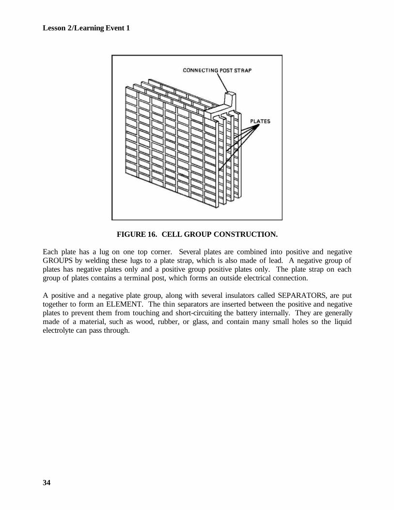
FIGURE 16. CELL GROUP CONSTRUCTION.
Each plate has a lug on one top corner. Several plates are combined into positive and negativeGROUPS by welding these lugs to a plate strap, which is also made of lead. A negative group ofplates has negative plates only and a positive group positive plates only. The plate strap on eachgroup of plates contains a terminal post, which forms an outside electrical connection.
A positive and a negative plate group, along with several insulators called SEPARATORS, are puttogether to form an ELEMENT. The thin separators are inserted between the positive and negativeplates to prevent them from touching and short-circuiting the battery internally. They are generallymade of a material, such as wood, rubber, or glass, and contain many small holes so the liquidelectrolyte can pass through.
34
Lesson 2/Learning Event 1
When the assembled element, consisting of the positive and negative plate groups and separators, isimmersed in electrolyte, it becomes a CELL. The voltage of a charged cell as measured with anopen circuit is about 2.1 volts, regardless of the size of the cell. For practical purposes we generallyjust say that the voltage of the cell is 2 volts. In order to obtain more than 2 volts from a battery,several cells are used and connected in series (negative to positive). For example, a 6-volt batterywill contain three cells and a 12-volt battery six cells. The cell terminals are connected by weldingthem to connector straps.
All the cells of a battery are placed in a one-piece container or case that is divided intocompartments. Each compartment is the container for one cell. The bottom of each cellcompartment generally has raised ribs for the element to rest on. The area between the ribs servesas sediment space. During use, the active material on the plates gradually sheds and falls into thesediment space. The entire container is made of hard rubber or some other insulating material thatis resistant to acid and to mechanical shock.
35
Lesson 2/Learning Event 1
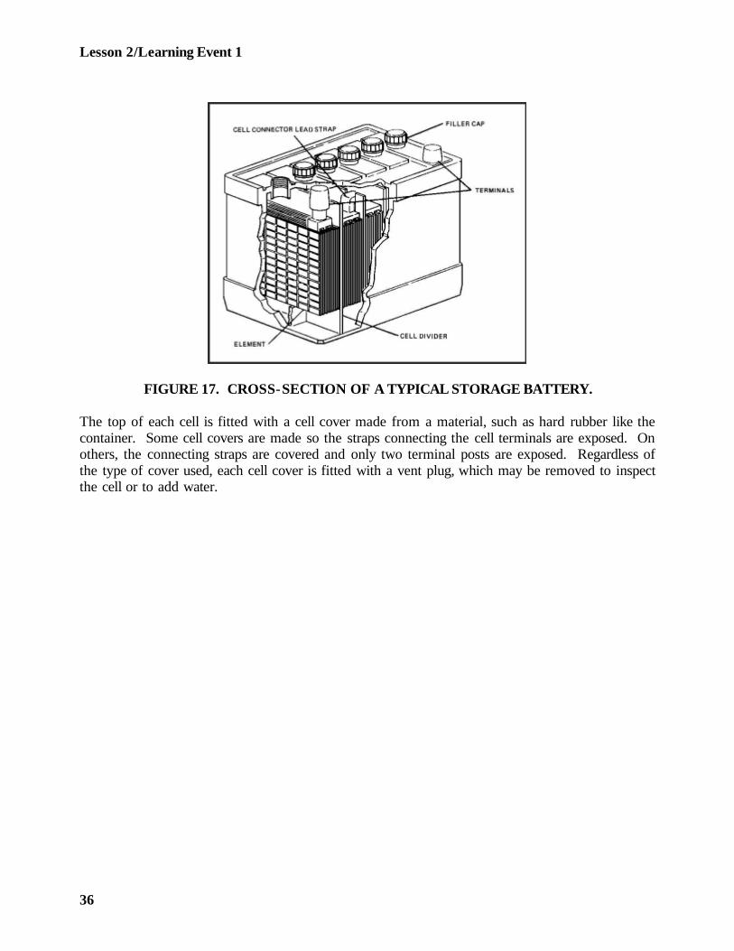
FIGURE 17. CROSS-SECTION OF A TYPICAL STORAGE BATTERY.
The top of each cell is fitted with a cell cover made from a material, such as hard rubber like thecontainer. Some cell covers are made so the straps connecting the cell terminals are exposed. Onothers, the connecting straps are covered and only two terminal posts are exposed. Regardless ofthe type of cover used, each cell cover is fitted with a vent plug, which may be removed to inspectthe cell or to add water.
36
Lesson 2/Learning Event 1
To seal the battery after the cell cover is installed, the space between the edges of the cell coversand the container is filled with an acid-resistant compound. Some form of seal is also used wherethe terminal post extends through the cover.
The vent plug (filler cap) contains a small hole to permit the escape of gas formed in the cell. Aseries of baffles may be built into the plug so the gas must pass around them in leaving the cell.The baffles prevent electrolyte from splashing out through the venthole. Also, any mist from theelectrolyte is collected here and returned to the cell.
Batteries designed for use in tactical vehicles are waterproof. The vent plugs will not allow water toenter the cells during fording operations but will still permit gases to escape. This is done by apressure vent valve in the vent plug. The valve closes to external water pressure and opens torelease internal gas pressure.
Electrical power comes from the battery through two TERMINAL POSTS. The posts are tapered,and the positive terminal is slightly larger than the negative terminal. The cable clamps are alsomade in two sizes, to reduce the chances of connecting a battery in reverse.
The cells of the battery are filled with a mixture of sulfuric acid and distilled water, the electrolyte.Electrical energy is produced by the chemical action of the sulfuric acid on the plates. Theelectrolyte also serves as a carrier for the electric current inside the battery. The electrolyte of afully charged battery contains about 38 percent sulfuric acid by weight (about 27 percent byvolume).
37
Lesson 2/Learning Event 1
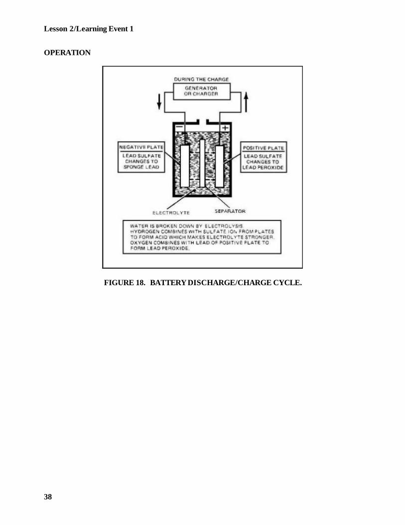
OPERATION
FIGURE 18. BATTERY DISCHARGE/CHARGE CYCLE.
38

Lesson 2/Learning Event 1
FIGURE 18. BATTERY DISCHARGE/CHARGE CYCLE (CONTINUED).
39
Lesson 2/Learning Event 1
Now that you are familiar with the construction of the automotive battery, let's consider thechemical reaction that takes place in the battery.
A battery cell is said to be fully charged when the electrolyte is full strength. The active material ofthe negative plates consists of spongy lead, and the active material of the positive plates consists oflead peroxide.
When a load is connected to the battery, electrons flow from the negative plates to the positiveplates. The battery is said to be "discharging." Chemical changes take place inside the batteryduring discharging:
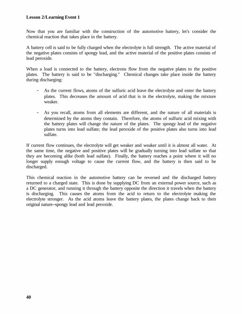
- As the current flows, atoms of the sulfuric acid leave the electrolyte and enter the batteryplates. This decreases the amount of acid that is in the electrolyte, making the mixtureweaker.
- As you recall, atoms from all elements are different, and the nature of all materials isdetermined by the atoms they contain. Therefore, the atoms of sulfuric acid mixing withthe battery plates will change the nature of the plates. The spongy lead of the negativeplates turns into lead sulfate; the lead peroxide of the positive plates also turns into leadsulfate.
If current flow continues, the electrolyte will get weaker and weaker until it is almost all water. Atthe same time, the negative and positive plates will be gradually turning into lead sulfate so thatthey are becoming alike (both lead sulfate). Finally, the battery reaches a point where it will nolonger supply enough voltage to cause the current flow, and the battery is then said to bedischarged.
This chemical reaction in the automotive battery can be reversed and the discharged batteryreturned to a charged state. This is done by supplying DC from an external power source, such asa DC generator, and running it through the battery opposite the direction it travels when the batteryis discharging. This causes the atoms from the acid to return to the electrolyte making theelectrolyte stronger. As the acid atoms leave the battery plates, the plates change back to theiroriginal nature--spongy lead and lead peroxide.
40
Lesson 2/Learning Event 1
- As a battery is charged, some of the water in the electrolyte is broken down and passesoff in the form of gas. If charging is continued after the battery is fully charged, theamount of gas given off increases and the battery overheats. This is called overchargingand can damage the battery. The gas given off by a battery during the charging process isexplosive and can be easily ignited by a spark.
- Repeated charging and discharging slowly wears out the battery. It causes the leadperoxide to fall off the positive plates into the sediment space in the bottom of thecontainer. The sediment may build up high enough to cause a short circuit between thenegative and positive plates, but normally the cell will be worn out before the sedimentreaches the bottom of the plates.
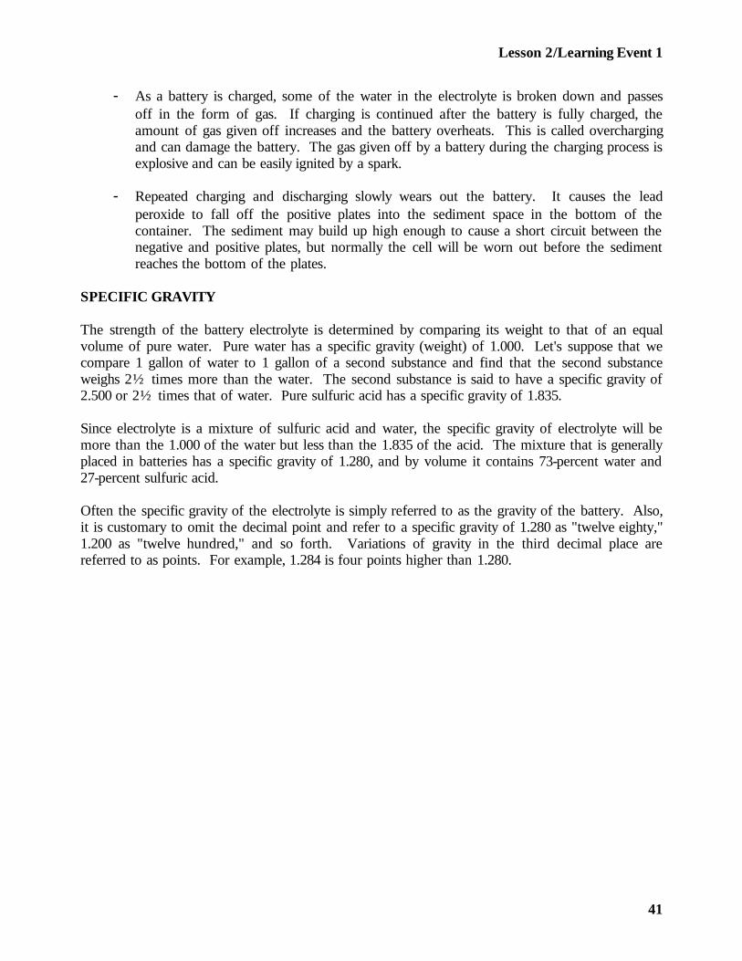
SPECIFIC GRAVITY
The strength of the battery electrolyte is determined by comparing its weight to that of an equalvolume of pure water. Pure water has a specific gravity (weight) of 1.000. Let's suppose that wecompare 1 gallon of water to 1 gallon of a second substance and find that the second substanceweighs 2½ times more than the water. The second substance is said to have a specific gravity of2.500 or 2½ times that of water. Pure sulfuric acid has a specific gravity of 1.835.
Since electrolyte is a mixture of sulfuric acid and water, the specific gravity of electrolyte will bemore than the 1.000 of the water but less than the 1.835 of the acid. The mixture that is generallyplaced in batteries has a specific gravity of 1.280, and by volume it contains 73-percent water and27-percent sulfuric acid.
Often the specific gravity of the electrolyte is simply referred to as the gravity of the battery. Also,it is customary to omit the decimal point and refer to a specific gravity of 1.280 as "twelve eighty,"1.200 as "twelve hundred," and so forth. Variations of gravity in the third decimal place arereferred to as points. For example, 1.284 is four points higher than 1.280.
41
Lesson 2/Learning Event 1
VOLTAGE AND CAPACITY
There is a distinct difference between the voltage and capacity of a battery.
This difference can be easily seen by picturing two cans of water, one small and the other large,placed on top of a building. If the water from both cans is poured over the side of the building,the pressure or force it has when it hits the ground will depend on the distance it falls. Thedistance is the same regardless of which can the water comes from. This is comparable to batteryvoltage since voltage is electrical pressure. Each cell of an automotive battery has slightly over 2volts. This is true regardless of the size of the cell.
Now, let's imagine that one of the cans contains one gallon of water and the other can five gallons.You can see that if the water is poured from both cans at the same rate, water can be poured fivetimes as long from the large can. From another viewpoint, if we empty both cans in the samelength of time, the large can pours five times as much water in the same amount of time. This iscomparable to battery capacity. More battery capacity is obtained by giving the electrolyte moreplate surface to contact. This can be done by making the plates larger or by using a larger numberof plates.
Battery voltage and capacity are different, and each one has a definite effect upon the other as wellas the circuit.
We know that the battery must supply the correct amount of voltage to push just the right amountof current through the circuits. Too much voltage will cause too much current to flow, which willburn out bulbs, and so forth. If battery voltage is too low, the current flow will not be enough andthe circuits will not operate right.
When a load is connected to the battery, the current flow will cause the battery voltage to drop dueto internal resistance in the battery cells. The amount of voltage drop under a load is affected bythe following:
- The larger the capacity of the battery, the less the voltage drops.
- As the battery's state of charge gets lower, the more the voltage drops.
- The greater the current flow, the greater the voltage drop.
42

Lesson 2/Learning Event 1
- As the battery wears out, active material drops off the plates, which reduces the battery'scapacity and causes a larger voltage drop under the load.
- As outdoor temperature drops, the electrolyte gets thicker, which slows down its actionand causes a larger voltage drop during cold weather.
BATTERY RATINGS
The current required by the electrical systems of two vehicles are often different, even though theyrequire the same voltage. For instance, both the ¼- and 5-ton trucks have 24-volt electricalsystems, but the batteries used in the ¼- ton truck will not supply enough current to satisfactorilycrank the large engine of the 5-ton truck.
We can tell which battery has a larger capacity or current-producing capability by physical size, justlike judging a bigger can will hold more water, but that is not an exact measurement.
The amount of water the cans will hold is measured in pints, quarts, or gallons. Battery capacity ismeasured in ampere-hours, which is the number of amperes the battery will deliver multiplied bythe number of hours the battery will deliver it. For example, suppose a battery will deliver 5amperes for 20 hours, then 5 amperes multiplied by 20 hours equals 100 ampere-hours.
If the ampere-hour rating is based on nothing more than the method described above, the ratingwould change if the rate of discharge changed. Suppose that we increase the load on the batteryfrom 5 to 10 amperes. The battery would produce the 10 amperes for a period less than 20 hours,so its rating would be less than 100 ampere-hours. As you can see, some standard procedure mustbe used to rate the ampere-hours so that the ratings will mean the same in all cases.
The capacity of automotive batteries is rated by a standard procedure known as the 20-hour rating.This rating gives the number of ampere-hours a battery will deliver if it is discharged at a uniformrate for 20 hours, at a temperature of 80°, and with a battery voltage of 1.75 volts per cell at theend of the 20-hour period.
Two sizes of batteries, type 2HN and 6TN, are commonly used in tactical wheeled vehicles. Bothtypes are 12-volt batteries. The smaller 2HN battery is rated 45 ampere-hours; the larger 6TNbattery is rated 100 ampere-hours.
43
Lesson 2/Learning Event 1
TESTING AUTOMOTIVE BATTERIES
Through use and age, the capacity of a battery decreases. This is due to some of the activematerial dropping off the plates and the build-up of a hard coating of sulfate on the plates. Becauseof this, testing the gravity of the battery with a hydrometer may not always reveal the truecondition of the battery. The electrolyte may be strong enough, but the battery capacity may bereduced to a point where the available current supply is too small. This condition can be detectedby making a high-rate discharge test of the battery.
Do not perform a high-rate discharge test when the specific gravity of the electrolyte is 1.225 or lessor if the variation of specific gravity between cells is more than 25 points. After charging, thebattery should be allowed to sit for several hours before a high-rate discharge test.
High-rate discharge testing instruments vary a great deal. Always perform a high-rate discharge testaccording to instructions for the test instrument you are using. In use, the test instrument draws ahigh current from the battery and the battery voltage is read on a voltmeter during the discharge.The correct amount of voltage will vary depending on the test instrument used.
If a high-rate discharge tester is not available, batteries can still be tested if they are installed in thevehicle. This is done by using an ordinary voltmeter to measure the battery voltage while crankingthe engine. The starter motor serves as the high-current load. Refer to -20 technical manual forthe vehicle for the exact procedures and correct voltage readings.
CONNECTING BATTERIES IN SERIES AND SERIES-PARALLEL
As you know, tactical vehicles have 24-volt electrical systems, twice the voltage supplied by each 12-volt battery used. In addition, some of the vehicles demand more current for cranking than the100 ampere-hour battery can supply. To satisfy the increased voltage and current requirements,more than one battery is used in each vehicle. To satisfy the specific requirements of differentvehicles, the batteries are connected in series or series-parallel.
44
Lesson 2/Learning Event 1
In order to increase voltage, the batteries are connected in series. Recall that in a series circuit thecurrent has only one path to follow; therefore, the same current will flow through all batteries whenthey are connected in series. A series connection of two batteries is made by connecting thenegative terminal post of one battery to the positive terminal post of another battery. Batteriesconnected in series should have the same ampere-hour rating. A voltage source equal to the sumof both batteries is then available at the two remaining terminal posts. The ampere-hour rating ofbatteries connected in series is the same as the smallest battery by itself. For instance, some trucksuse two 6TN batteries which are rated at 12 volts and 100 ampere-hours each. The batteries areconnected in series to furnish a power source of 24 volts and 100 ampere-hours.
In order to increase the ampere-hour rating, the batteries are connected in parallel. In a parallelcircuit the current has more than one path to follow. Batteries connected in parallel must have thesame voltage rating. To connect two batteries in this manner, the positive terminal posts of bothbatteries are connected together and then the negative terminals of the batteries are connected.Each battery will now furnish half the current flowing in the load so their ampere-hour ratings willbe added together, but the voltage will be the same as one battery alone. The parallel connectionof batteries when used in tactical wheeled vehicles is combined with the series connection and isknown as the series-parallel connection.
45
Lesson 2/Learning Event 1
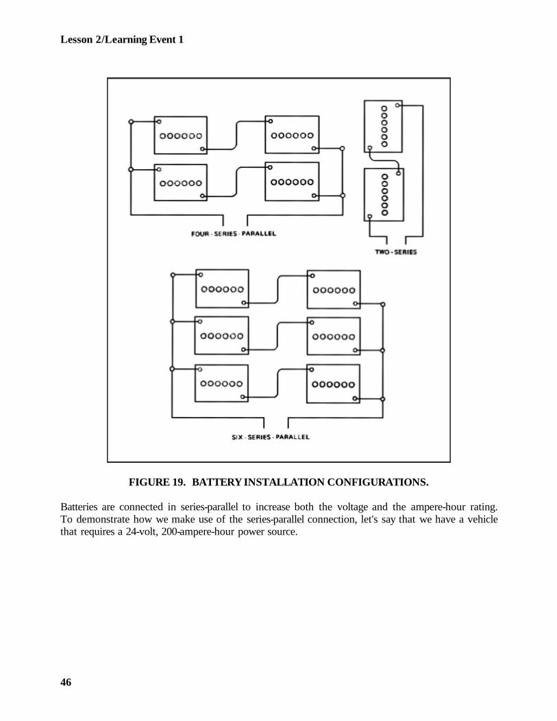
FIGURE 19. BATTERY INSTALLATION CONFIGURATIONS.
Batteries are connected in series-parallel to increase both the voltage and the ampere-hour rating.To demonstrate how we make use of the series-parallel connection, let's say that we have a vehiclethat requires a 24-volt, 200-ampere-hour power source.
46

Lesson 2/Learning Event 1
We will use four 12-volt, 100-ampere-hour batteries. The batteries are first set apart in pairs. Ineach pair, the batteries are connected in series so they will provide 24 volts and 100 ampere-hoursper pair. Then, the two pairs are connected in parallel to increase the capacity rating to 200ampere-hours.
47
Lesson 2/Learning Event 2
Learning Event 2:DESCRIBE MAINTENANCE PROCEDURES FOR AUTOMOTIVE BATTERIES
PREVENTIVE MAINTENANCE
In nearly all cases of early failure of automotive batteries, the cause can be traced to a lack ofpreventive maintenance. When given proper care, batteries generally will give no trouble until theyare worn out, unless damaged by accident or enemy action. The vehicle operator and theorganizational level mechanic are responsible for performing preventive maintenance on thebatteries of vehicles assigned to the unit.
Each time the vehicle is started and often during its operation, the driver should check the battery-generator indicator located on the dash panel. The battery-generator indicator on tactical vehicles isa meter that shows the level of battery voltage. It has a scale marked off in three colors: red,yellow or amber, and green.
When the ignition switch is first turned on, the indicator hand will usually point to the yellowsection, which is the center part of the scale. If the hand points to the red at the left side of thescale, the battery is in a low state of charge. (The hand may point to the green scale on the right ifthe battery was just recently charged at a high rate.)
If the battery charge is low, find out the cause and make necessary corrections. If a battery isallowed to remain in a low state of charge for very long, the sulfate formed in the plates willharden, and it will be impossible or very difficult to return the battery to a fully charged condition.
When the engine is started, the battery-generator indicator hand will move to the right if thecharging system is operating properly. The hand will point to the left half of the green part of thescale when the battery is fully charged.
If the hand moves into the right half of the green scale, the battery is being overcharged. (Onsome indicators this part of the scale is red instead of green.) The operator should have thecharging system checked immediately before the battery or charging system is damaged.Overcharging overheats the battery, causing it to lose water at a fast rate, and can warp the platescausing permanent damage.
48
Lesson 2/Learning Event 2
If the vehicle is equipped with an ammeter instead of a battery-generator indicator, the operatorshould check the position of the ammeter hand often during operation. For a fully charged battery,the ammeter should show a high rate of charge immediately after the vehicle is started. Afterabout 15 minutes of operation, the charge rate should drop to about 5 amperes. When the batteryis partly discharged before starting, the high-charge rate will continue for a longer period. If theammeter does not register a charge or if the high-charge rate continues, the charging circuit shouldbe checked immediately.
After operation, check the battery to see that it is clean, securely mounted, and not leaking. Cableterminals should be clean and secure on the battery posts. All vent caps should be present andtight.
The batteries should be thoroughly inspected and serviced once a week by doing the proceduresexplained below. Either the operator or the mechanic may be called upon to perform theseprocedures.
- Inspect the tops of the batteries very carefully and clean them if needed. They must bekept clean to prevent them from discharging through collected dirt, and so forth. Toclean, tighten the vent plugs and wash the batteries with a brush dipped in an alkalinesolution, such as a mixture of bicarbonate of soda (baking soda) and water. Foaming willoccur due to the reaction between the cleaning solution and battery electrolyte. After thefoaming stops, rinse off the batteries with clean water and wipe dry with a clean cloth.
- Inspect the battery terminals to see that they are clean and the cable clamps are tight andfree of corrosion. If they are corroded, remove the cable clamps and clean the clampsand the battery posts with a solution as described above. Then, reconnect and tighten thecable clamps. Coat the terminals with a light coat of general-purpose grease to fight offcorrosion. Dirt will collect on the grease, but it can be removed each time the batteriesare cleaned and the terminals recoated with grease. When disconnecting the batterycables, always disconnect the ground cable first to prevent a short circuit. Whenconnecting the cables, connect the ground cable last.
49

Lesson 2/Learning Event 2
- Remove and inspect the vent plugs to see that the ventholes are open. Use a short lengthof stiff wire to run through the ventholes to make sure they are not plugged, but becareful not to damage the check valves in vent plugs on waterproof batteries.
- Inspect the electrolyte level and add water if it is low. Filling instructions are located onthe vent plugs or the cell covers. When correct, the electrolyte level will be at least 3/8inch above the plates. Distilled water should be used to fill batteries if it is available; if itis not available, the second choice is rainwater.
- Do not store battery water in metal containers. Minerals in water from streams or wells,or from water stored in metal, can damage and shorten the life of a battery. Water that isused for drinking can be used, but only when distilled water or rainwater is not available.A battery will be damaged less by clean water that has some minerals than by letting theelectrolyte level drop below the top of the plates.
- Check the specific gravity of each cell with an optical battery/antifreeze tester.
- Inspect the battery hold-downs to make sure that the batteries are held properly in theircarriers. If a battery is loose, it may bounce around and damage the container or shakethe plates loose inside the cells. On the other hand, if the hold-downs are drawn tootight, the container may crack.
OPTICAL BATTERY/ANTIFREEZE TESTER
Since the amount of sulfuric acid in the electrolyte decreases as the battery discharges, the gravityof the battery also decreases as the battery's state of charge decreases. By using a tester, known asan optical battery/antifreeze tester, to measure the gravity of the electrolyte, we can tell the battery'sstate of charge.
The gravity of the battery is affected by temperature. When heated, the electrolyte expands so itoccupies more space. When the temperature drops, the electrolyte contracts and takes up lessspace. Therefore, warm electrolyte weighs less than the same volume of cold electrolyte, so warmelectrolyte has a lower specific gravity than cold electrolyte.
50

Lesson 2/Learning Event 2
Electrolyte mixed for normal use will test 1.280 at 80°F temperature. (This is the temperature ofthe electrolyte and not the surrounding air.) At ordinary temperatures, it is not necessary toconsider any variations when testing the gravity of a battery. However, any large variation above orbelow 80° is very important when deciding the true state of battery charge.
The state of the battery charge indicated by gravity readings is shown below.
Other factors to consider when you test the gravity of a battery are the level of the electrolyte andhow well the electrolyte is mixed.
51
Lesson 2/Learning Event 2
The electrolyte should be at the correct level in the cell. Water in the electrolyte evaporates; theacid does not. If the water has evaporated enough so the electrolyte level is low, the mixture willbe strong and the gravity reading will be high. On the other hand, if the battery has been overfilledwith water, the electrolyte will be weakened and the reading will be low.
When water is added, it will tend to remain at the top of the cell, and you should not testimmediately after adding water. If water must to be added before a reading, the battery should becharged for one to two hours to mix the electrolyte before the optical battery/antifreeze tester isused.
Gravity readings will not tell the true state of the electrolyte just after a battery has been dischargedat a high rate (such as just after the engine has been cranked for a long time). In this case, theacid has been used up next to the plates but the electrolyte near the top of the plates is still strong.The optical battery/antifreeze tester will read a higher state of charge than actually exists. Theelectrolyte will show a true reading if the battery is allowed to stand unused for several hours or ifit is charged for one to two hours.
MEASURING SPECIFIC GRAVITY WITH THE OPTICAL BATTERY/ANTIFREEZE TESTER
This tester is quick, accurate, and reliable. There is no guesswork or arithmetic involved. Thetester automatically adjusts for temperature.
The plastic cover and the measuring window must be clean and dry. Wipe clean with a soft cloth.Clean the eyepiece lens. Use clean water to clean dirty areas.
Swing the plastic cover down until it rests against the measuring window.
Make a separate test for each battery cell.
Using the black dipstick, place a few drops of electrolyte onto the exposed portion of the measuringwindow.
52
Lesson 2/Learning Event 2
WARNING
Be careful not to splash electrolyte onto you or the equipment.
Point the tester toward a bright light source. When you look through the eyepiece lens, you willsee a rectangle with two calibrated scales - battery charge readings on the left scale, antifreezereadings on the right.
The electrolyte sample will divide the rectangle with an area of light and an area of shadow. Youread the scale where they meet.
A full charge is 1.225 specific gravity for tropical electrolyte and 1.280 specific gravity for temperateelectrolyte.
If below 1.180 specific gravity for tropical electrolyte and 1.225 specific gravity for temperateelectrolyte, replace the battery with a fully charged one if you cannot charge it in the field.
COLD WEATHER
Battery capacity is greatly reduced by low temperatures because the electrolyte thickens and is lessactive. In addition, the engine is harder to crank so the starter motor requires more current. Toperform satisfactorily in cold weather, the battery must be kept in peak condition. So when thetemperature drops, you will have to keep a closer watch on the battery.
In cold weather do not let the specific gravity drop below 1.250 if you expect the vehicles to start.When the temperature is colder than -20°F, the vehicles should be stored inside where it is warm,if possible. If they must be parked outside, the batteries should be heated during long periods ofstandby; otherwise, they will not take a charge or have enough capacity for normal use.
The electrolyte is also subject to freezing; the exact freezing point depends on the specific gravity.In a fully charged battery, the electrolyte will freeze at -90°F. As the specific gravity drops, thefreezing point rises. The following table shows the freezing point for various specific gravities.
53
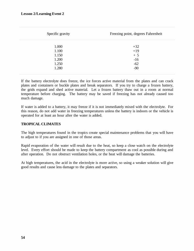
Lesson 2/Learning Event 2
Specific gravity Freezing point, degrees Fahrenheit
1.000 +321.100 +191.150 + 51.200 -161.250 -621.280 -90
If the battery electrolyte does freeze, the ice forces active material from the plates and can crackplates and containers or buckle plates and break separators. If you try to charge a frozen battery,the grids expand and shed active material. Let a frozen battery thaw out in a room at normaltemperature before charging. The battery may be saved if freezing has not already caused toomuch damage.
If water is added to a battery, it may freeze if it is not immediately mixed with the electrolyte. Forthis reason, do not add water in freezing temperatures unless the battery is indoors or the vehicle isoperated for at least an hour after the water is added.
TROPICAL CLIMATES
The high temperatures found in the tropics create special maintenance problems that you will haveto adjust to if you are assigned in one of those areas.
Rapid evaporation of the water will result due to the heat, so keep a close watch on the electrolytelevel. Every effort should be made to keep the battery compartment as cool as possible during andafter operation. Do not obstruct ventilation holes, or the heat will damage the batteries.
At high temperatures, the acid in the electrolyte is more active, so using a weaker solution will givegood results and cause less damage to the plates and separators.
54

Lesson 2/Learning Event 2
Electrolyte solution used for tropical climates should have a specific gravity of 1.200 to 1.225. Youwill have to weaken the solution yourself. Do this by drawing electrolyte from a supply that isalready mixed to 1.280 specific gravity and add battery water until the mixture has a specific gravityof 1.200 to 1.225. You will need to add about 1 quart of water to 1 gallon of electrolyte.
If the battery was in use before it was sent to the tropics, change the electrolyte in the followingmanner. Make sure that the battery is fully charged, so there will be no acid left in the plates.Then, remove the vent plugs and tip the battery upside down to drain all the old electrolyte. Refillthe battery with electrolyte that has been weakened to 1.200 to1.225 specific gravity.
WARNING
Be careful to avoid getting any of the electrolyte on yourself or your clothes.The acid can cause painful burns and will eat holes in your clothing.
The following table shows various specific gravities and the state of charge for batteries withweakened electrolyte for use in the tropics.
Specific gravity of electrolyteused in tropical climates State of battery charge
1.200 - 1.225 Fully charged1.180 75 percent1.135 50 percent1.090 25 percent1.045 Discharged
When the electrolyte in a battery has been weakened, a tag showing the full charge specific gravityshould be attached to the battery. These batteries should also be identified by a white dot about 1inch in diameter painted on the top of the battery where it can be easily seen.
55
Lesson 2/Learning Event 2
SLAVING
Normally, the charging system of a vehicle will keep the vehicle's batteries charged. Occasionally,due to excessive cranking, repeated short drives, or a fault in the electrical system, the batteries willbecome discharged. If the vehicle is in the field where no external method of charging is available,you will probably have to start it by towing or slaving the electrical system of another vehicle.
To slave a vehicle with discharged batteries, you must use heavy-duty jumper cables and connect itsdead batteries to the good batteries of a second vehicle. Stay alert when connecting the jumpercables. The hookup must always be positive to positive and negative to negative. If either of thevehicles has an AC charging system, the rectifier will be burned out if you even momentarily touchthe cables to the wrong terminals.
Never try to slave one vehicle from another one that has a power source with a smaller ampere-hour capacity rating. In other words, do not slave a 10-ton tractor with four 6TN 100 ampere-hourbatteries from a ¼- ton truck with two 2HN 45 ampere-hour batteries. This will only lead to moretrouble.
After connecting the jumper cables, run the live vehicle with good batteries at 1,800 revolutions perminute (RPM) for a short while. This allows its charging system to put a slight charge in thedischarged batteries which helps a lot when you attempt to crank the dead vehicle. While crankingthe dead vehicle, keep the live one running at 1,800 RPM so you can use the power created by itsgenerator.
Remember that batteries will be damaged if left in a discharged state for long. After you get theslaved vehicle started, make sure the vehicle is kept in operation long enough to fully recharge itsbatteries. If this is not possible, arrange for the batteries to be charged from an external source. Ifsome defect caused the batteries to discharge, get that defect corrected immediately.
Some vehicles are equipped with slave receptacles so a slave (jumper) cable can be easily plugged in.Both vehicles involved must be equipped with these receptacles. A special two-conductor slavecable that fits the receptacles is provided. The proper positive-to-positive and negative-to-negativeconnection for slaving is made by merely plugging the one-piece slave cable into the slavereceptacles of the two vehicles.
56
Lesson 2/Learning Event 2
CHARGING METHODS
Whenever the gravity of a battery drops below 1.225 (1.135 in tropical climates), it is best torecharge it with a battery charger under controlled conditions. The two principal ways of chargingare constant current and constant potential (voltage). The method you use will depend on theequipment and facilities available.
Constant-current charging is usually done only at installations where a regular battery shop is set up.Electrical power is furnished by the 110-volt current supplied by the high lines. Since the 110-voltsupply is usually AC, which will not charge batteries, it must be changed to DC. This is usuallydone by rectifiers.
After the incoming 110-volt power has been changed to DC, it must not be connected directly to asingle 12-volt battery or the battery will be ruined. A resistance must be placed in the circuit tolimit the current. This can be done by connecting a number of lamps in parallel. A 110-volt, 100-watt lamp consumes about 1 ampere of current, so four bulbs will permit 4 amperes to flow. Avariable resistor of the proper value can be used instead of lamps and adjusted to give the desiredcurrent.
Several batteries are generally connected in series when charging by the constant-current method, sothe power that is consumed by the current-limiting resistance is reduced. When the batteries areconnected, their combined voltage should never be higher than the charging voltage. Allow 2.5volts per cell when you add up the battery voltage. All batteries in the same series should be inabout the same condition. Batteries being charged by the constant-current method must bechecked often, particularly in the final stages, to avoid overcharging.
Battery chargers supplied for use in the field are the constant-potential type. A charger usuallyconsists of a DC generator powered by a gasoline engine. They are made with 7½- and 15-voltoutputs or with a 15- and 28-volt output.
When using the battery charger to charge one 12-volt battery, connect its 15-volt output or loadterminals to the battery terminals. Connections must be positive-to-positive and negative-to-negative. If more than one battery is to be charged from the 15-volt output, they must beconnected in parallel. If you connect the batteries in series, their voltage will be higher than thecharging voltage and the charger could not force current through the batteries.
57
Lesson 2/Learning Event 2
To charge 12-volt batteries from the 28-volt output of a charger, connect two batteries in series,then connect them to the 28-volt load terminals. To charge more than two batteries, you mustconnect them in series-parallel. The batteries in each series group should be in about the samecondition.
When a battery is first placed on a constant-potential charging system, its voltage is much lowerthan the charging voltage, so a high current will flow. As the battery is charged its voltageincreases, but the charging voltage remains constant. This causes the current to decrease as thebattery is charged and to taper off to a very slow rate. Less attention is required near the end, butcare must be taken to prevent overheating the battery at first. The constant-potential batterycharger is generally equipped with a variable resistor so the operator has some control over thecharging rate.
CHARGING PROCEDURES
Batteries should be charged only in the open air or a well-ventilated room because of the gases theyexpel. Before attempting to charge a battery, give it a thorough cleaning and inspection. Do notwaste your time on batteries that are cracked or damaged in any way that will make themunserviceable. Place good batteries on a board or wooden rack. Never stack them on top of eachother or on the ground or a concrete floor.
Check and record the specific gravity of each cell of all the batteries to be charged. Add water tobring the electrolyte to the proper level. Arrange and connect the batteries for charging. Allbatteries connected in one series group should have about the same specific gravity readings. Makesure all the vent plugs are secure and the vents are not plugged, then begin the charge.
Watch closely for overheating or excessive gassing for the first few minutes of charge. If eitheroccurs, reduce the charging rate. For best results, the battery electrolyte should not exceed 110°Ftemperature. The battery should gas very little when it is first placed on charge, but steady gassinglater on when the battery nears full charge is normal.
58
Lesson 2/Learning Event 2
Check the specific gravity of the battery often while it is being charged. Just how often willdepend on the rate of charge. If a charge rate of 2½ amperes for 2HN batteries or 5 amperes for6TN batteries is being used, check the gravity hourly when the batteries near full charge. You mayreduce the time between checks if the charge rate is decreased. Add water to replace any lostduring the charge. A battery is fully charged when three successive readings show no further risein specific gravity.
When the battery is charged, remove it from the charger and clean its top to remove any acid.Inspect the battery once again for any cracks that may have opened due to the charging process.Screw the vent plugs tightly in place. If the battery has handles and the paint on them is worn,apply a coat of acid-resistant black paint.
PLACING BATTERIES IN SERVICE
New batteries that you receive will probably be charged and dry. If they are, you will have to fillthem with electrolyte in preparing them for service. The instructions received with new batterieson how to prepare them for service should always be followed. In general, the followinginstructions apply:
Remove and discard the seals from the ventholes of the vent plugs. Remove the vent plugs and filleach cell with electrolyte to the proper level. The temperature of the battery must be at least 60°F.Let the battery stand for 30 minutes after filling to allow the plates and separators to becomesoaked, then check the specific gravity of each cell. The electrolyte level must be correct.
The battery is now ready for use unless one or more of the following conditions exist:
- The specific gravity of any cell is below 1.250 after the 30-minute stand.
- The battery will not be used for 12 hours after filling.
- The battery is going into service in temperatures below zero.
If any of the above conditions exists, the battery must be charged. If you have the time andequipment, it is always best to charge the battery regardless of the conditions to ensure longerservice life. After charging, the specific gravity should be at or very near 1.280.
59

Lesson 2/Learning Event 2
When batteries are selected for installation in a vehicle, they should be matched. This applies toboth new and charged batteries. If two batteries with one weaker than the other are placed in avehicle, the vehicle's charging system will overcharge the stronger battery in an attempt to chargethe weak one. This causes overheating and loss of water in the stronger battery, shortening its life.In matching batteries, you should pair batteries that have about the same specific gravity andvoltage.
60

Lesson 2
PRACTICE EXERCISE
1. The positive and negative plates in the lead-acid battery are made mechanically strong bythe use of a
a. separator.b. grid.c. paste.
2. What is the state of charge of a battery that reads 1.280 at 100°F?
a. Goodb. Fairc. Poor
3. The level of the electrolyte above the battery plates should be at least
a. 1/8 inch.b. 3/8 inch.c. ¾ inch.
4. In the field, you may have to start a vehicle with discharged batteries by
a. AC or DC current.b. cleaning the terminals.c. towing the vehicle or slaving the batteries.
5. What should be done if the battery electrolyte freezes?
a. Thaw at room temperatureb. Charge battery at a slow ratec. Add acid to lower freezing point
61

Lesson 2
ANSWERS TO PRACTICE EXERCISE
1. b (page 33)
2. a (page 51)
3. b (page 50)
4. c (page 56)
5. a (page 54)
62
Lesson 3/Learning Event 1
LESSON 3
FUNDAMENTALS OF ELECTRICAL TEST EQUIPMENT
TASK
Describe the purpose, construction, and operation of electrical test equipment.
CONDITIONS
Given information on voltmeters, ammeters, and ohmmeters; low voltage circuit testers;multimeters; and simplified test equipment for internal combustion engines (STE/ICE).
STANDARDS
Answer 70 percent of the multiple-choice items covering electrical test equipment.
REFERENCES
TM9-4910-571-12&PTM9-8000Applicable LVCT TMApplicable multimeter TM
Learning Event 1:DESCRIBE PRINCIPLES OF METERS
INTRODUCTION
If we did not know how to measure, where would we be? Throughout each day, we make variousmeasurements. For example, we squeeze out the right amount of toothpaste onto the toothbrush.When we go grocery shopping, we pay according to weight or size of the products we buy. Wemeasure time with our wristwatches and clocks.
63
Lesson 3/Learning Event 1
Another example of daily measurement is the water and electricity supplied to our homes. Thesemeasurements are made with meters that measure how much you use (volume or flowmeters).Water and electricity bills are based on these meter readings. You have probably seen at least oneof these meters as the electricity meter should be mounted on your house in plain view. Theseflowmeters, which are read by the "meter man," are only one of the many types of measuringdevices needed to show service personnel how a system is operating. Both water and electricitysystems work best in a certain pressure range. Both systems, therefore, include pressure-measuringdevices at various points along the line.
Automotive electrical systems also require various measurements to indicate how they are operating.The automotive electrical system actually resembles the water system in your home in many ways.
VOLTMETER
You know that voltage is measured with a voltmeter. Let's compare the flow of voltage with awater system.
Have you ever opened the valve or spigot at your bathroom sink and the water flowed very slowly?The next time you opened the valve a few hours later the waterflow was back to normal. Theproblem was probably caused by a pressure loss in the water system. If you could have looked at apressure gage on the water system, you would have found the pressure was lower than normalwhen the water flowed too slowly. This tells you that the pressure in a water system affects theflow. The same is true of an automotive electrical system. When the pressure (voltage) drops, itcauses the flow (current) to drop also and makes electrical components work improperly. Forexample, electric motors run too slow, solenoids or electromagnets do not have enough strength tooperate, and lights and lamps do not burn brightly.
Let's compare a simple electrical system to a simple water system and see how the voltmetermeasures pressure. Notice that the electrical system, shown in Figure 20 contains a battery on theleft. The battery is connected to the load on the right. The load could be any electricalcomponent, such as a light bulb, electromagnet, or an electric motor. The current flows from thebattery to the load, then through the load and back to the battery. Like the water system, theelectrical pressure gage (voltmeter) must sample the pressure or voltage in this circuit.
64
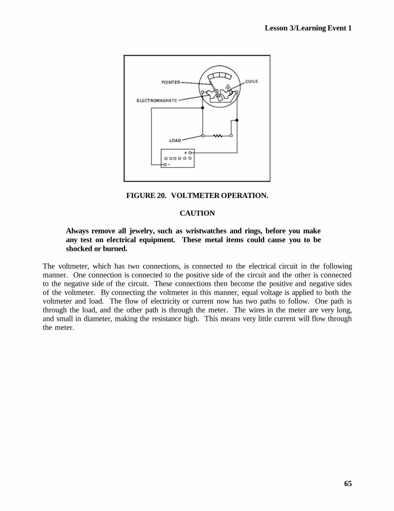
Lesson 3/Learning Event 1
FIGURE 20. VOLTMETER OPERATION.
CAUTION
Always remove all jewelry, such as wristwatches and rings, before you makeany test on electrical equipment. These metal items could cause you to beshocked or burned.
The voltmeter, which has two connections, is connected to the electrical circuit in the followingmanner. One connection is connected to the positive side of the circuit and the other is connectedto the negative side of the circuit. These connections then become the positive and negative sidesof the voltmeter. By connecting the voltmeter in this manner, equal voltage is applied to both thevoltmeter and load. The flow of electricity or current now has two paths to follow. One path isthrough the load, and the other path is through the meter. The wires in the meter are very long,and small in diameter, making the resistance high. This means very little current will flow throughthe meter.
65
Lesson 3/Learning Event 1
The resistance of the load varies depending on the type of load, such as a small lamp compared toa large motor. However, the resistance of the load is generally less than that of the meter. For thisreason, most of the current in the circuit flows through the load. The two paths are side by side orparallel. We say the voltmeter is connected parallel to the circuit.
The voltmeter contains a pointer or hand known as the indicating pointer. This pointer isconnected to an electromagnet. The pointer and electromagnet are mounted on a pivot or hingepin and can be moved or swung around like a door. A very small coil spring, known as ahairspring, holds the pointer on zero when the meter is not in use. It also returns the pointer tozero when the meter is in use if the voltage stops or the meter is disconnected.
When voltage is applied to the voltmeter, it moves the current through the electromagnet. Theelectromagnet then forces or moves the pointer away from zero. The amount it moves depends onhow much voltage is applied, because, as the voltage is increased the current will increase, and asthe voltage decreases so does the current. The more pressure or voltage applied to the circuit, themore current that will flow and the voltmeter will, therefore, change as the voltage changes.
The main thing to remember is that the voltmeter is connected parallel to the main circuit. If thevoltmeter was connected so that all the current within a circuit passed through the meter, it wouldbe connected in series. If a voltmeter was accidentally connected in this manner, it would in mostcases indicate the source voltage. However, the load component(s) would not operate normally dueto the high resistance the voltmeter placed in the circuit. When the voltmeter is used to test abattery with no load applied, positive is connected to positive and negative is connected to negative.However, in that case the meter and the battery make up the complete circuit.
Voltmeters do not all look alike. There are many types and sizes of portable voltmeters. Large,complex electrical equipment has built-in voltmeters, because slight variations in voltage greatlyaffect the operation of this equipment. Operators or service personnel must constantly measure thevoltage on such equipment and make quick adjustments whenever needed.
66
Lesson 3/Learning Event 1
Automotive electrical systems are not as sensitive and are designed for more variation in voltage.Therefore, built-in voltmeters are not needed on vehicles. If the voltage varies more than isallowed or if the voltage is thought to be wrong, portable voltmeters are available to measure thevoltage. Some voltmeters are in separate cases while others are part of a combination-type meter.Two good examples of combination meters are the low-voltage circuit tester and multimeter.
Voltmeters vary depending on their model and use. For example, some voltmeters have only onescale and others have two or more scales. All portable voltmeters include flexible test leads, lengthsof wire with a male plug on the meter end and a test probe or an alligator clip on the other end.The test leads are usually color-coded red and black. The red lead is connected to the positiveterminal on the meter and the positive side of the circuit to be tested. The black lead is used toconnect the negative terminal of the meter to the negative side of the circuit.
There are two ways to connect the two test leads to the meter so that all ranges can be used. Inone method, the test leads are always connected to the same two terminal sockets of the meter,and a selector switch is used to select the proper range. The second method uses one commonterminal for the negative or positive lead, and the other lead is connected to a different terminal foreach range.
Why do we need more than one range on a voltmeter? Why not have one range from 0 to 500volts? That is not practical. Electrical test meters are most accurate in the center of the scale orrange. This means the 0- to 500-volt scale would be most accurate around 250 volts. The battery-generator voltage of most military vehicles is in the 24- to 28-volt range. You will therefore beusing the voltmeter to test voltages ranging from 5 volts to a fraction of 1 volt.
Suppose you were issued a voltmeter like the one in Figure 21. Do you think you could use it?Notice that the meter dial contains three ranges or scales, but the selector switch indicates there areactually four ranges. The ranges on this voltmeter are 0 to 1 volt, 0 to 10 volts, 0 to 20 volts, and 0to 50 volts.
The range or scale for 0 to 10 volts can also be accurately used when the selector switch is in the 0-to 1-volt position. The numbers on the 0- to 10-volt scale then become tenths of a volt. Forexample, 2 becomes 0.2 (two tenths) of a volt, 3 becomes 0.3 volt and 10 becomes 1.0 volt.
67
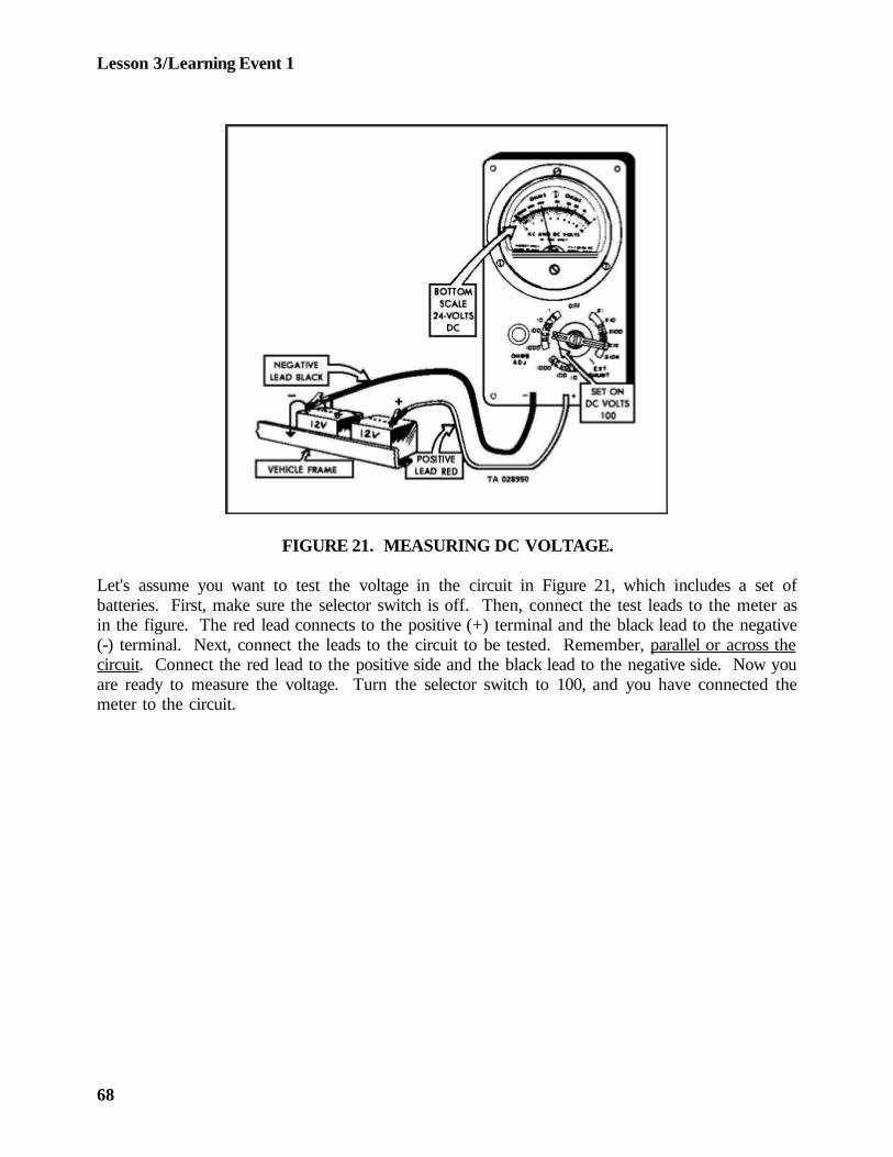
Lesson 3/Learning Event 1
FIGURE 21. MEASURING DC VOLTAGE.
Let's assume you want to test the voltage in the circuit in Figure 21, which includes a set ofbatteries. First, make sure the selector switch is off. Then, connect the test leads to the meter asin the figure. The red lead connects to the positive (+) terminal and the black lead to the negative(-) terminal. Next, connect the leads to the circuit to be tested. Remember, parallel or across thecircuit. Connect the red lead to the positive side and the black lead to the negative side. Now youare ready to measure the voltage. Turn the selector switch to 100, and you have connected themeter to the circuit.
68
Lesson 3/Learning Event 1
If the battery is charged and the load in this circuit is small, such as a small bulb, the meter shouldindicate close to 24 volts. Notice this is about the center of this scale. Let us say you are checkinga defective 24-volt circuit with a heavy load, such as a starter. When you switch the selector to 50,the meter indicates only approximately (about 12 volts). If you want to get a more exactmeasurement, switch the selector to 20. You are now using the 0 to 20 scale, and it is easier toread for this particular voltage.
CAUTION
You must turn the selector switch back to 50 or to OFF before this heavy loadis disconnected from the circuit. If you do not, the meter will be damaged ifthe voltage jumps past 20 volts when the load is disconnected.
Notice that ranges for the selector switch start with the highest range 0 to 50. As the selector isturned to the right, the ranges become smaller. This prevents burnout of the meter by the operatorhaving to go through the higher ranges first, once the operator leaves the OFF position.
Let us review what you have learned so far. We learned the automotive electrical system is inmany ways similar to a water system. We learned electrical pressure is measured with a voltmeteras water pressure is measured with a pressure gage. We have also learned how a voltmeter isconnected to an electrical circuit. We know this is only one of many measurements that can bemade on the automotive electrical system. Let us next see how current can be measured with anammeter.
AMMETERS
If we want to find out how much water is flowing through a pipe in a water system, we install aflowmeter, placed in the pipe in such a way that all of the water moving through the pipe goesthrough the meter. The meter "counts" (measures) the gallons of water that move through it.
The ammeter does the same thing in an electrical circuit. The ammeter measures the amount ofcurrent moving through the wire. While the flowmeter measures the water flow in gallons, theammeter measures the electrical current in amperes. The gallon is a unit of measure for water andother liquids; the ampere is a unit of measure for electrical current. Amperes are often called"amps" or "amps of current."
69
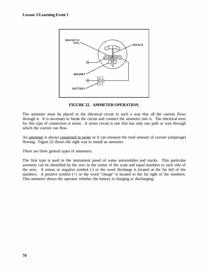
Lesson 3/Learning Event 1
FIGURE 22. AMMETER OPERATION.
The ammeter must be placed in the electrical circuit in such a way that all the current flowsthrough it. It is necessary to break the circuit and connect the ammeter into it. The electrical termfor this type of connection is series. A series circuit is one that has only one path or wire throughwhich the current can flow.
An ammeter is always connected in series so it can measure the total amount of current (amperage)flowing. Figure 22 shows the right way to install an ammeter.
There are three general types of ammeters.
The first type is used in the instrument panel of some automobiles and trucks. This particularammeter can be identified by the zero in the center of the scale and equal numbers to each side ofthe zero. A minus or negative symbol (-) or the word discharge is located at the far left of thenumbers. A positive symbol (+) or the word "charge" is located to the far right of the numbers.This ammeter shows the operator whether the battery is charging or discharging.
70
Lesson 3/Learning Event 1
The second type of ammeter has the zero located at the left side of the dial and numbersincreasing to the right side of the dial. This ammeter is found on many battery chargers. Itspurpose is to show the rate at which the battery is being charged.
The third type of ammeter is found in most automotive testing equipment. It can be identified bythe zero located close to the left end of the scale and the numbers increasing on each side of thezero. The right side increases much more than the left. Let's find out how this ammeter is used.
An ammeter resembles a voltmeter in many ways. It may contain one or more scales on its face ordial. Ammeters with only one scale, like voltmeters, are limited in use. Ammeters with two ormore scales generally have a terminal connection for each scale instead of a selector switch,especially if the ammeter is made to measure high amperage. Ammeters with terminal connectionsfor each range have one common terminal. One test lead is connected to this terminal; the other isconnected to the terminal of the range desired. The ammeter, like the voltmeter, may be aseparate meter or a part of a test instrument that contains other test equipment.
The electrical portion of the ammeter must be constructed to handle the amperage it must test. Aninternal shunt or resistor is built into many ammeters to help carry the current. Some ammetersare used to test very high amperage, and these meters are made to connect an external shunt orresistor to make the tests. This is the purpose of the exterior-shunt terminals on many ammeters.When the electrical leads are connected to these terminals, the external shunt assembly is includedin the meter circuit. All ammeter leads must be connected to the meter in the right polarity (red topositive, black to negative). As you now know, the circuit must be broken and the ammeter mustbe connected in series so that all current will pass through the ammeter or the external shunt.
An ammeter is easy to use, if you follow proper procedures:
- You should never try to connect the ammeter into a circuit under load. This will causearcing, when the test leads are connected, which could injure you as well as damage theequipment. This is especially true if the circuit carries a heavy amperage load. The loadcan generally be disconnected by opening a switch.
- The ammeter should never be connected while the vehicle engine is running.
71
Lesson 3/Learning Event 1
- Make sure that all switches are turned off including the master (battery) switch.
- You should always try to determine the amount of amperes or current that you are goingto measure. This information can be found in the vehicle technical manual. If you arenot able to find what amperage the circuit does carry, start with the highest range on theammeter and work down. Through this method you will not damage the ammeter byusing a range too small to handle the amperage. In fact, it is always best to start testingon a scale higher than you think is necessary for a particular circuit.
Let us follow the hookup of an ammeter in a circuit with a fully charged 12-volt battery, a load,and a switch to connect or disconnect the load to or from the battery. The load is a large lampsimilar to the headlamps on a vehicle. The information included with this circuit indicates thereshould be about 10 amperes flowing when the switch is closed. The ammeter has a range from 0to 10 amperes; however, we will use the 0- to 50-amp range just in case the flow happens to bemore than 10 amperes, which could harm the meter in the 10-ampere range. We connect the red(positive) test lead to the common terminal of the meter because it is marked positive (+). Theblack (negative) lead is then connected to the 50-ampere terminal on the meter. We know theammeter must be connected in series with the circuit, so we have connected the red lead to thepositive side of the circuit and the black lead to the negative side of the circuit.
In a generator output rate test, the current flow will be from the generator back to the battery. Toread upscale, the leads must be connected to the circuit in reverse of a load test. That would bered (positive) lead to negative, and black (negative) lead to positive. Any load on the circuit wouldthen be indicated to the left of zero or downscale. The charging rate from the generator would beindicated upscale.
Once you are connected correctly for a load test, complete the circuit by closing the switch.Current will then flow from the battery, through the load, through the ammeter to the switch, andback to the battery. As the current passes through the ammeter, the amount of current flow will beindicated on the upscale side of the ammeter.
The amperage capacity of an ammeter depends on its construction. The ammeter used for the loadtest above can accept no more than 100 amperes through the meter. With an external shunt,greater amounts of current can be measured. You will learn how a shunt is used later.
72
Lesson 3/Learning Event 1
From what we have covered so far, you see that the automotive electrical system can be comparedwith a water system. Both systems work under pressure, and the pressure can be measured. Wealso learned that pressure causes a flow in the system when the system is in use. This flow canalso be measured. The amount of flow in each system depends on the amount of pressure andhow much resistance is in the circuit or system. In the water system, the size of pipes and valvescan create resistance in the system, and the waterflow changes if the pressure is increased or theresistance is decreased. The flow of electricity in a circuit also depends on several factors. Oneimportant factor is resistance.
How can we know if the resistance in a circuit is correct? One way is to measure the voltage andamperage, and if the voltage is correct but the amperage is not, you call safely assume the resistanceis wrong. We can measure resistance by itself using an ohmmeter.
OHMMETERS
Anything that moves meets resistance (opposition to movement). Remember what happens to thespace capsule when it returns after a trip in space? It gets so hot it has to have a heat shield tokeep the astronauts from being burned to death. That heat is caused by the resistance of air as thespace capsule moves through it. The faster the capsule moves, the greater the resistance of the air,and resistance to motion always creates heat.
Resistance (opposition) to the movement of electricity in a wire also produces heat. Sometimes wewant a lot of resistance in a wire. For example, the wires in the burners on an electric stove get redhot, and the wires in a light bulb get hot enough to shine and produce light. At other times, wewant as little resistance as possible in an electrical circuit, because the resistance does cause heat andloss of voltage and reduces the amount of current that can flow.
The unit of measure for electrical resistance is the ohm. The instrument used to measure theresistance in an electrical circuit is an ohmmeter.
73
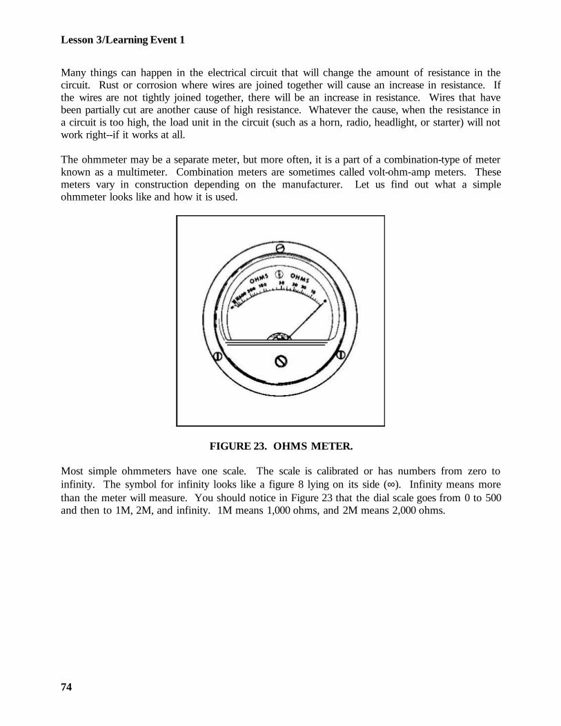
Lesson 3/Learning Event 1
Many things can happen in the electrical circuit that will change the amount of resistance in thecircuit. Rust or corrosion where wires are joined together will cause an increase in resistance. Ifthe wires are not tightly joined together, there will be an increase in resistance. Wires that havebeen partially cut are another cause of high resistance. Whatever the cause, when the resistance ina circuit is too high, the load unit in the circuit (such as a horn, radio, headlight, or starter) will notwork right--if it works at all.
The ohmmeter may be a separate meter, but more often, it is a part of a combination-type of meterknown as a multimeter. Combination meters are sometimes called volt-ohm-amp meters. Thesemeters vary in construction depending on the manufacturer. Let us find out what a simpleohmmeter looks like and how it is used.
FIGURE 23. OHMS METER.
Most simple ohmmeters have one scale. The scale is calibrated or has numbers from zero toinfinity. The symbol for infinity looks like a figure 8 lying on its side (∞). Infinity means morethan the meter will measure. You should notice in Figure 23 that the dial scale goes from 0 to 500and then to 1M, 2M, and infinity. 1M means 1,000 ohms, and 2M means 2,000 ohms.
74
Lesson 3/Learning Event 1
An ohmmeter is actually an ammeter that measures current flow in thousandths of an ampere.This type of ammeter is referred to as a milliammeter. Most ohmmeters consist of themilliammeter, a battery, some form of current-limiting resistance unit, and the case. In mostohmmeters, the resistance unit is actually two resistors. One is a fixed resistor and the other is avariable resistor (rheostat). The simple ohmmeter has two test leads connected to two terminals.
The ohmmeter has many uses. By measuring resistance, it locates shorted or open circuits andchecks circuit continuity (zero resistance). For example, consider a wire that is broken somewhereinside a wiring harness. You can see the ends of the wire where they connect in the circuit, butthe rest of the wire is hidden inside the harness. The ohmmeter can check the continuity of thewire and prove if it is broken.
Use the following procedures when beginning a test with the ohmmeter:
- Remove the ohmmeter test leads from the case and connect them to the two terminals onthe ohmmeter. If the wire to be tested is in a vehicle, turn off all electricity in thevehicle's electrical system. THIS IS IMPORTANT. The ohmmeter has its own low-voltage battery, and the meter will be burned out if higher voltage enters it.
- The next step is to zero the ohmmeter. When the meter is not in use, the pointer orhand will be on the infinity mark. To zero the meter, touch the test lead ends together tocomplete a circuit. If the meter hand does not move to zero, turn the zero-ohmadjustment knob until it does. This changes the resistance of the variable resistor.
- You will find as the meter ages that you have to adjust the zero-ohm adjustment knobmore and more to make up for the weaker battery. When the hand will not come backto zero with any adjustments, the battery is too weak and must be replaced.
- When the ohmmeter is zeroed, connect one lead to each end of the wire to be tested. Ifthe wire is not broken, the tested wire will complete the circuit through the ohmmeter.The hand will move to zero. If the wire is broken, the circuit will not be completed. Thehand will not move.
75
Lesson 3/Learning Event 1
The ohmmeter is also valuable for testing switches. Suppose you have a small on-off switch thatyou think is not working, even though the lever seems to click normally. The switch has twoelectrical terminals. To test the switch with an ohmmeter, first zero the ohmmeter as explainedabove, then connect one test lead to each terminal of the switch. With the switch in the OFFposition, the ohmmeter hand should not move. Then move the switch lever to the ON position.The ohmmeter hand should move to zero.
If the ohmmeter hand remained on zero in both positions, ON and OFF, what would this tell you?(Remember what makes the hand move to zero: a complete circuit through the ohmmeter andswitch.) This tells you the switch is not working properly; it does not break (open) the circuit. Onthe other hand, if the ohmmeter indicated infinity in both ON and OFF positions, the circuit is notbeing closed. This means the switch is not making contact inside.
You now see how the ohmmeter can be used to locate open circuits caused by a defective switch ora broken wire.
You can also use the ohmmeter to check for shorts or an unwanted grounding effect. Let's goback to that simple on-off switch and check it to see if it is grounded. You know that the vehiclechassis acts as one wire or part of the circuit. If the switch is mounted on metal, the circuitthrough the switch must be insulated from the metal or the circuit will be grounded out. If theinsulation fails, due to cracks, breaks, wear, and so forth, the contacts or terminals touch the metalframe and ground out. Test the switch for grounding by connecting one ohmmeter test lead to themetal frame of the switch and the other to one terminal. The ohmmeter hand should not move ifthe switch is not grounded. Then, change the switch position and look at the meter. Test bothterminals in this manner. If the ohmmeter hand moves from infinity, the switch is grounded.You have a complete circuit or continuity from a terminal through the switch metal frame. Theswitch must be replaced.
So far, we have tested using infinity and zero, but how about the numbers in between these two?The numbers are used when you want to measure resistance.
76
Lesson 3/Learning Event 1
As a wheeled vehicle repairer, you will not be removing or replacing many resistors; however, youwill be working with many electrical components. Many of these components, functioningproperly, do place resistance in an electrical circuit. Earlier in this lesson we learned thesecomponents are called the load in a circuit. If the resistance of these components is not thespecified resistance, the component or the electrical circuit will not function properly. Let's see howthe ohmmeter is used to measure the resistance of the load.
Let's assume we have a circuit that is fuse-protected. (Some circuits are circuit-breaker protected.)Our circuit includes a set of batteries, an electromagnet, an on-off switch, and a 3-amp fuse. Forthe purpose of this test, let's say the circuit blows the fuse each time a replacement fuse is installedand the switch is closed. The circuit has been checked, and the wires are not grounded. The fuseis of the right amperage (3 amperes) for the circuit. The battery voltage is normal (24 volts). Thefuse will not last long enough to make an amperage load test on the circuit. The only componentin this circuit that creates any measurable resistance is the load--the electromagnet. According tothe wiring schematic, the electromagnet should place 12 ohms of resistance on the circuit. We willdisconnect the electromagnet from the circuit and measure the electromagnet's resistance.
Do not forget to zero the ohmmeter first. Remember, the circuit to be tested is hooked up inseries with the ohmmeter.
For the purpose of this test, let's say the ohmmeter hand indicates 6 ohms of resistance. This isonly half of the 12 ohms the electromagnet should have. Could this difference cause the 3-amperefuse to blow? Remember the laws you learned so far about electricity: one law states if theresistance increases in a circuit and the voltage remains the same, the current or amperagedecreases.
In this case, we have the opposite of that law. The resistance decreases, the voltage remains thesame, and therefore, the amperage increases. The amperage increases to more than 3 amperes, andthe fuse blows, opening the circuit. This protects the circuit from an overload that would otherwisedamage the wiring and components.
You now know how the ohmmeter can help you in testing circuits and switches and locatingelectrical system troubles. The ohmmeter you will probably use will be part of a multimeter, whichis covered later in this lesson.
77
Lesson 3/Learning Event 1
Remember, the ohmmeter is actually an ammeter and is always connected in series with a circuit.ALWAYS disconnect the vehicle battery or batteries from the circuit BEFORE connecting theohmmeter to the circuit. You will use the ohmmeter to measure resistance, locate open circuits(broken wires), and shorts (touching wires). You can also check the operation of switches andlocate grounds in a circuit.
The ohmmeter is a valuable test meter--take care of it!
So far, you have learned about the voltmeter, ammeter, and ohmmeter as separate test meters orinstruments. It is more practical to combine these meters into one unit. You will be using twocombined instruments: the low-voltage circuit tester and the multimeter.
78
Lesson 3/Learning Event 2
Learning Event 2:DESCRIBE CONSTRUCTION AND USE OF LOW-VOLTAGE CIRCUIT TESTERS
INTRODUCTION
The military low-voltage circuit tester (LVCT) is a heavy-duty test instrument. When you open thecase, you will see two test meters that you are already familiar with, the ammeter and voltmeter,but there are some connections and controls not found on the separate ammeter and voltmeter.Some repairers shy away from the LVCT, but it is really simple to use. Once you learn what eachconnection and control is used for, the LVCT will make your troubleshooting problems a lot easierto solve.
CONSTRUCTION
When you are assigned to a unit that is authorized an LVCT, learn to use it as soon as possible. Ifyour unit is issued a second LVCT that does not look anything like the first, do not send it back.The Army now uses several different models of LVCTs with only one Federal stock number(FSN). This means your unit may order an LVCT under FSN 4910-092-9136 and receive one ofseveral different testers. All LVCTs include one ammeter and one voltmeter; however, the controlsand connections vary.
The LVCT in your unit could be made by any of the following firms: Auto Test, Inc., Model10308; Atomic Engineering, Model TV100; Austin Continental Industries, Model 1060/A; ElectroMechanisms, Inc., Model 1060; Ram Meter, Inc., Model 62F151; Allen Electric and EquipmentCompany, Model 30-92; or Futrenics Industries, Inc., Model 225-01. If you tried to learn each ofthese LVCTs from one lesson, you would be very confused. However, if you know how to useone, you easily learn how to use the others by following the instructions. Let's see what the AllenModel 30-92 LVCT looks like and how to use it.
The Allen Model 30-92 LVCT is a portable (hand carried) test instrument. It is used for testinglow voltage, DC, and electrical circuits on automotive vehicles. The unit includes a voltmeter andammeter, to measure voltage and amperage, and a load bank that is an adjustable resistance unit.The load bank is used for current tests of values up to 100 amperes on a 24-volt circuit.
79
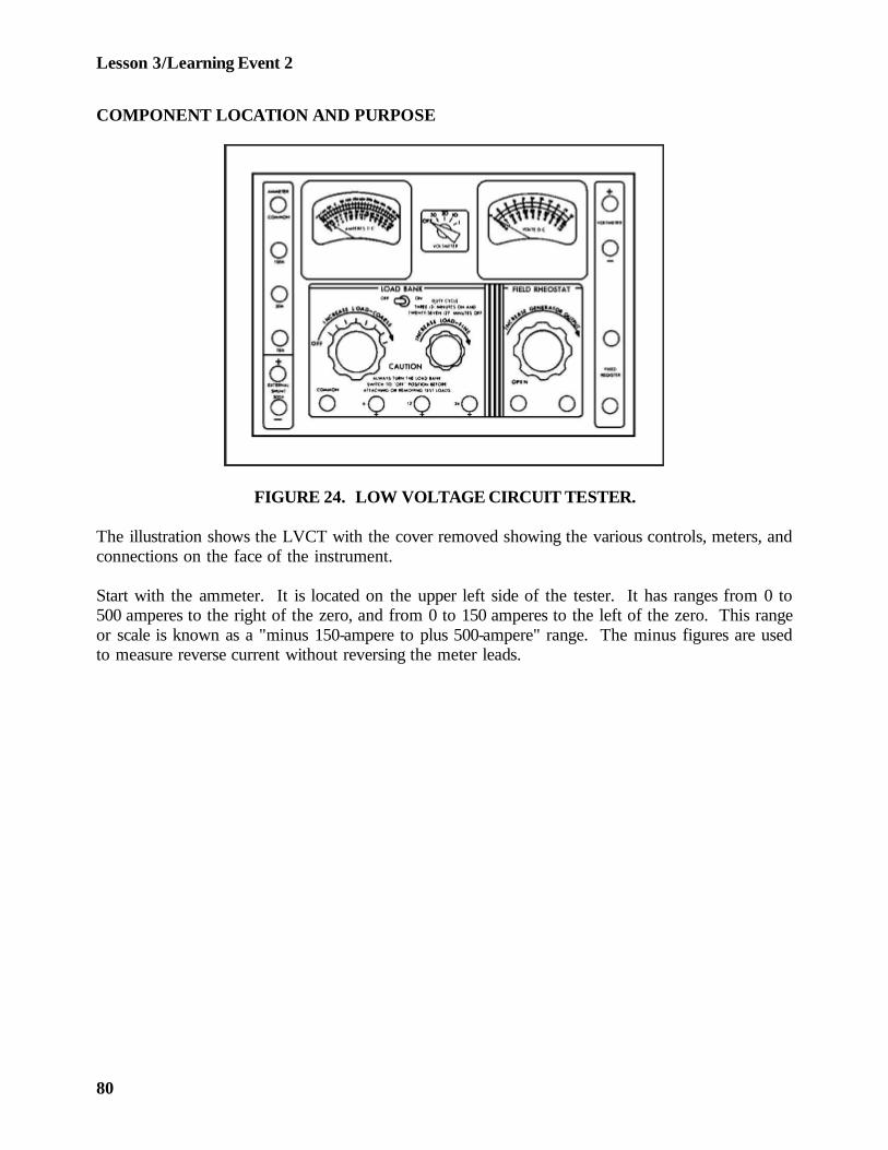
Lesson 3/Learning Event 2
COMPONENT LOCATION AND PURPOSE
FIGURE 24. LOW VOLTAGE CIRCUIT TESTER.
The illustration shows the LVCT with the cover removed showing the various controls, meters, andconnections on the face of the instrument.
Start with the ammeter. It is located on the upper left side of the tester. It has ranges from 0 to500 amperes to the right of the zero, and from 0 to 150 amperes to the left of the zero. This rangeor scale is known as a "minus 150-ampere to plus 500-ampere" range. The minus figures are usedto measure reverse current without reversing the meter leads.
80
Lesson 3/Learning Event 2
The coarse load control is located directly below the ammeter. This is part of the load bankcontrols. The control has eight positions and an OFF position. During a 24-volt load operation,each position adds 12.5 amperes of load when the knob is turned to the right. If the tester is beingused for a 12-volt load operation, each position from 2 to 8 adds 6.5 amperes of load. (Position 1of the coarse load control has no control during the 12-volt load operation.) The load bank alsohas a fine load control located to the right of the coarse load control. This is used when you wantan amperage load between the 12.5-ampere positions for 24 volts. It can also be used for the 12-volt load operation.
The field rheostat control, located in the lower right of the tester, is a variable resistor. It is used tochange the generator output. This control should be left in the open position when the fieldrheostat is not being used.
The voltmeter in the upper right of the tester has two scales, four rows of numbers, and fourranges that can measure from 0 to 50 volts. The 0 to 10 scale is also used as an accurate 0- to 1-volt scale or range. The voltmeter has a range selector switch located to its lower left. The switchto the left of the voltmeter dial is used to turn the load bank on or off and should be left in theOFF position when not in use.
The compartment along the right-hand side of the tester is used to store test leads. There areseven separate leads and an external shunt. The leads consist of four 16-gage (light) leads (threeblack and one red), two 6-gage heavy leads (one black and one red), and one black jumper lead.The 16-gage leads are used to connect the voltmeter to a circuit and to connect the field rheostat toa generating circuit. The two 6-gage leads are used to connect the adjustable load bank, ammeter,and the fixed resistor to a circuit. The black jumper lead can be used anywhere it is needed in acircuit with low amperage. The external shunt consists of two large and two small leads. It is usedwhen measuring loads from -150 amperes to +500 amperes.
The area above the ammeter and voltmeter has long slots cut in the metal. These slots allow air tocirculate through the LVCT for cooling. It is very important, when the meter is in use, that theyare not covered in any way.
81
Lesson 3/Learning Event 2
Many terminals or connections are located around three front sides of the LVCT. We will startwith the terminals to the left of the ammeter. The first two terminals are used to connect theexternal shunt to the LVCT. The terminals are polarity marked (+) and (-). The small red lead ofthe shunt is connected to the positive (+) terminal and the black lead to the negative (-) terminal.
The top of the terminal is the head of a screw. It is knurled and rough so it will not slip in yourfingers. The screw is threaded into a long, smooth nut. The nut has a hole bored at right anglesto the threaded screw hole, and the test lead has a long pin on the meter end, which fits into thishole. To make a connection, loosen the knurled screwhead by hand. Unscrew the knurled screwuntil the test lead pin will slide through the hole. Then turn the knurled screw in until it is snug onthe pin. Always tighten by hand only. All of the test lead connections are connected in thismanner.
Just below the external shunt connections you will see two straps. Each strap can be connected totwo terminals. These straps are called links because they are a link of a circuit when they areconnected. We could say they are actually a switch because they can be used to open or close acircuit. The upper link is used with the external shunt.
The next four terminals are used with the ammeter. The 6-gage test leads are connected to theseterminals. Three of the terminals are marked negative (-), and each of the three matches one ofthe scales or ranges on the ammeter. The fourth terminal is marked COMMON and is thereforethe positive (+) connection for the three ranges. For example, if you wish to measure a currentflow of 20 to 30 amperes, you would connect the leads to the LVCT as follows: the red leadpositive to the common terminal and the black lead to the -50A (ampere) terminal. The other endsof the leads would be connected in series with the circuit to be tested.
The next two terminals, located below the fine load control, are marked 24V and 12V respectively.These terminals are used with the COMMON terminal when placing a load on a circuit with theload bank. The 6-gage test leads are also used with these terminals, because heavy amperage (up to100 amperes on 24-volt circuits) can be forced to flow through these terminals. The black lead isconnected to the common terminal when using the load bank. The red lead is then connected tothe 12- or 24-volt terminal, depending on which voltage circuit is being tested.
82
Lesson 3/Learning Event 2
The next two terminals are used to connect a fixed resistor to a circuit. The resistor is located inthe LVCT and is rated at 0.25 (¼ ohm) of resistance. It is used to test some types of voltageregulators.
The next two terminals are marked FIELD RHEOSTAT. These terminals are used to connect theadjustable resistor to a circuit. The field rheostat is used to change the strength of theelectromagnet in generators, thereby changing the generator output. It can also be used to add avaried amount of resistance in other electrical circuits, if desired.
The last two connections or terminals are marked VOLTMETER. One terminal is marked positive,and the other is marked negative. These terminals are the connections for the voltmeter and arelocated right beside it. The 16-gage color-coded test leads (red/black) are used with these voltmeterterminals. The voltage range selector between the two meters connects the terminals to the properrange on the voltmeter.
The off-on switch between the two meters is used to turn the load bank on and off. It is alwaysleft in the OFF position except when the load bank is in use.
As you can see, it is easy to use the LVCT for simple tests. During this lesson, we discussed onlyone type of LVCT to help you learn what the tester is and what it is used for. Each LVCT has aninstruction booklet. If you have any questions on how to use the tester, always refer to theinstruction booklet.
83
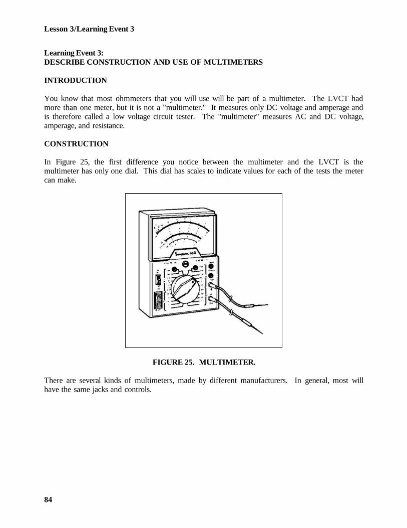
Lesson 3/Learning Event 3
Learning Event 3:DESCRIBE CONSTRUCTION AND USE OF MULTIMETERS
INTRODUCTION
You know that most ohmmeters that you will use will be part of a multimeter. The LVCT hadmore than one meter, but it is not a "multimeter." It measures only DC voltage and amperage andis therefore called a low voltage circuit tester. The "multimeter" measures AC and DC voltage,amperage, and resistance.
CONSTRUCTION
In Figure 25, the first difference you notice between the multimeter and the LVCT is themultimeter has only one dial. This dial has scales to indicate values for each of the tests the metercan make.
FIGURE 25. MULTIMETER.
There are several kinds of multimeters, made by different manufacturers. In general, most willhave the same jacks and controls.
84
Lesson 3/Learning Event 3
The jacks for various tests are usually located around the edges of the meter. There may be acommon jack. This is used for the negative lead for all tests. The positive lead is placed in theappropriate jack for the test being made. In some multimeters a range selector switch is usedinstead of separate jacks for each range, and these meters have common positive and negativejacks.
The rheostat knob is used to zero-adjust the meter for resistance tests.
The switch knob is used to position components of the meter in the proper circuit for the test to bemade.
The meter dial usually has three scales:
- One scale is for DC measurements. It can be used for either voltage or current.
- Another scale is the ohms scale. Remember, the scale is read from right to left. In otherwords, if there is no resistance in a circuit, the pointer will go all the way to the right or to0 ohms. As resistance increases, the pointer will stay farther to the left.
- Another scale is for AC voltages.
You must remember that all meter scales will not be the same. You must use each meter inaccordance with the way it is designed.
As you gain experience in automotive electrical system repair, you will learn the approximateresistance of each component. For example, you will learn that if the circuit is connected with lightwires (18 gage or smaller) the current flow is going to be low. By dividing the approximate currentflow (amperes) into the voltage, you will get some idea what the resistance should be. Alwayscheck the specifications for a system or component to get the exact amount. You should be able tofind either the current or resistance for most components in the technical manual.
85
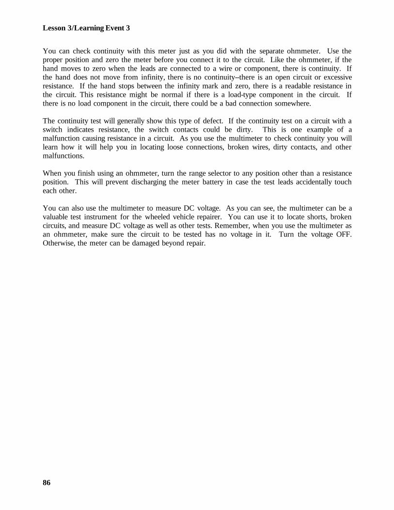
Lesson 3/Learning Event 3
You can check continuity with this meter just as you did with the separate ohmmeter. Use theproper position and zero the meter before you connect it to the circuit. Like the ohmmeter, if thehand moves to zero when the leads are connected to a wire or component, there is continuity. Ifthe hand does not move from infinity, there is no continuity--there is an open circuit or excessiveresistance. If the hand stops between the infinity mark and zero, there is a readable resistance inthe circuit. This resistance might be normal if there is a load-type component in the circuit. Ifthere is no load component in the circuit, there could be a bad connection somewhere.
The continuity test will generally show this type of defect. If the continuity test on a circuit with aswitch indicates resistance, the switch contacts could be dirty. This is one example of amalfunction causing resistance in a circuit. As you use the multimeter to check continuity you willlearn how it will help you in locating loose connections, broken wires, dirty contacts, and othermalfunctions.
When you finish using an ohmmeter, turn the range selector to any position other than a resistanceposition. This will prevent discharging the meter battery in case the test leads accidentally toucheach other.
You can also use the multimeter to measure DC voltage. As you can see, the multimeter can be avaluable test instrument for the wheeled vehicle repairer. You can use it to locate shorts, brokencircuits, and measure DC voltage as well as other tests. Remember, when you use the multimeter asan ohmmeter, make sure the circuit to be tested has no voltage in it. Turn the voltage OFF.Otherwise, the meter can be damaged beyond repair.
86
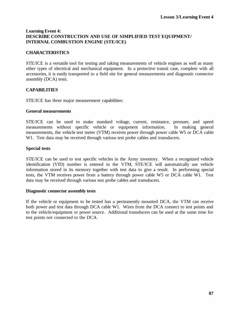
Lesson 3/Learning Event 4
Learning Event 4:DESCRIBE CONSTRUCTION AND USE OF SIMPLIFIED TEST EQUIPMENT/INTERNAL COMBUSTION ENGINE (STE/ICE)
CHARACTERISTICS
STE/ICE is a versatile tool for testing and taking measurements of vehicle engines as well as manyother types of electrical and mechanical equipment. In a protective transit case, complete with allaccessories, it is easily transported to a field site for general measurements and diagnostic connectorassembly (DCA) tests.
CAPABILITIES
STE/ICE has three major measurement capabilities:
General measurements
STE/ICE can be used to make standard voltage, current, resistance, pressure, and speedmeasurements without specific vehicle or equipment information. In making generalmeasurements, the vehicle test meter (VTM) receives power through power cable W5 or DCA cableW1. Test data may be received through various test probe cables and transducers.
Special tests
STE/ICE can be used to test specific vehicles in the Army inventory. When a recognized vehicleidentification (VID) number is entered in the VTM, STE/ICE will automatically use vehicleinformation stored in its memory together with test data to give a result. In performing specialtests, the VTM receives power from a battery through power cable W5 or DCA cable W1. Testdata may be received through various test probe cables and transducers.
Diagnostic connector assembly tests
If the vehicle or equipment to be tested has a permanently mounted DCA, the VTM can receiveboth power and test data through DCA cable W1. Wires from the DCA connect to test points andto the vehicle/equipment or power source. Additional transducers can be used at the same time fortest points not connected to the DCA.
87
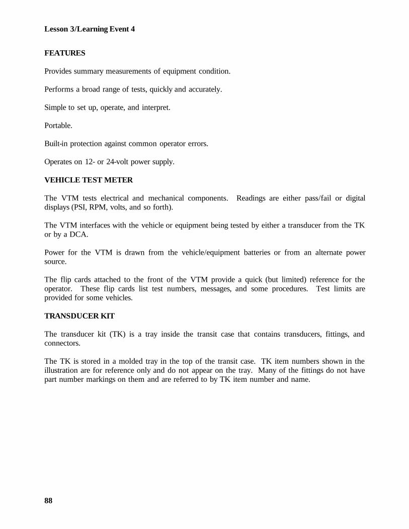
Lesson 3/Learning Event 4
FEATURES
Provides summary measurements of equipment condition.
Performs a broad range of tests, quickly and accurately.
Simple to set up, operate, and interpret.
Portable.
Built-in protection against common operator errors.
Operates on 12- or 24-volt power supply.
VEHICLE TEST METER
The VTM tests electrical and mechanical components. Readings are either pass/fail or digitaldisplays (PSI, RPM, volts, and so forth).
The VTM interfaces with the vehicle or equipment being tested by either a transducer from the TKor by a DCA.
Power for the VTM is drawn from the vehicle/equipment batteries or from an alternate powersource.
The flip cards attached to the front of the VTM provide a quick (but limited) reference for theoperator. These flip cards list test numbers, messages, and some procedures. Test limits areprovided for some vehicles.
TRANSDUCER KIT
The transducer kit (TK) is a tray inside the transit case that contains transducers, fittings, andconnectors.
The TK is stored in a molded tray in the top of the transit case. TK item numbers shown in theillustration are for reference only and do not appear on the tray. Many of the fittings do not havepart number markings on them and are referred to by TK item number and name.
88
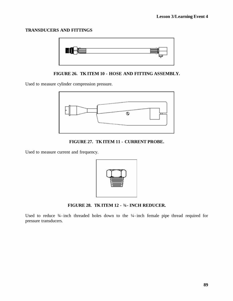
Lesson 3/Learning Event 4
TRANSDUCERS AND FITTINGS
FIGURE 26. TK ITEM 10 - HOSE AND FITTING ASSEMBLY.
Used to measure cylinder compression pressure.
FIGURE 27. TK ITEM 11 - CURRENT PROBE.
Used to measure current and frequency.
FIGURE 28. TK ITEM 12 - ¾- INCH REDUCER.
Used to reduce ¾- inch threaded holes down to the ¼- inch female pipe thread required forpressure transducers.
89
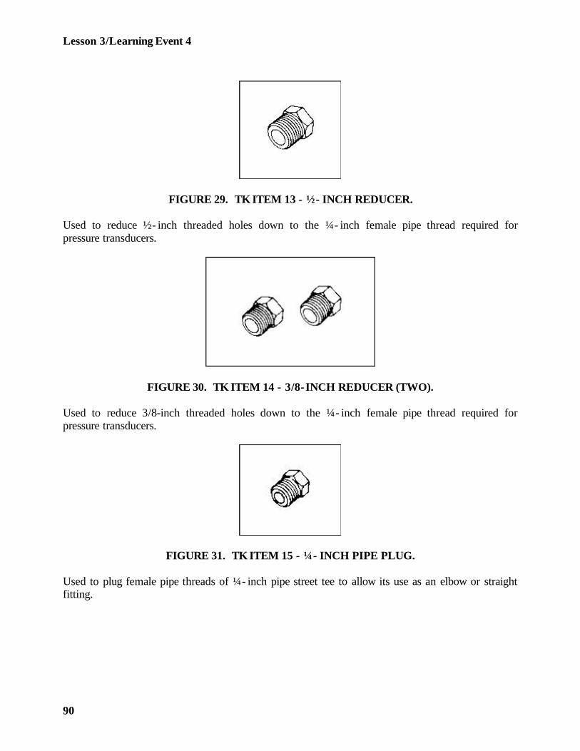
Lesson 3/Learning Event 4
FIGURE 29. TK ITEM 13 - ½- INCH REDUCER.
Used to reduce ½- inch threaded holes down to the ¼- inch female pipe thread required forpressure transducers.
FIGURE 30. TK ITEM 14 - 3/8-INCH REDUCER (TWO).
Used to reduce 3/8-inch threaded holes down to the ¼- inch female pipe thread required forpressure transducers.
FIGURE 31. TK ITEM 15 - ¼- INCH PIPE PLUG.
Used to plug female pipe threads of ¼- inch pipe street tee to allow its use as an elbow or straightfitting.
90
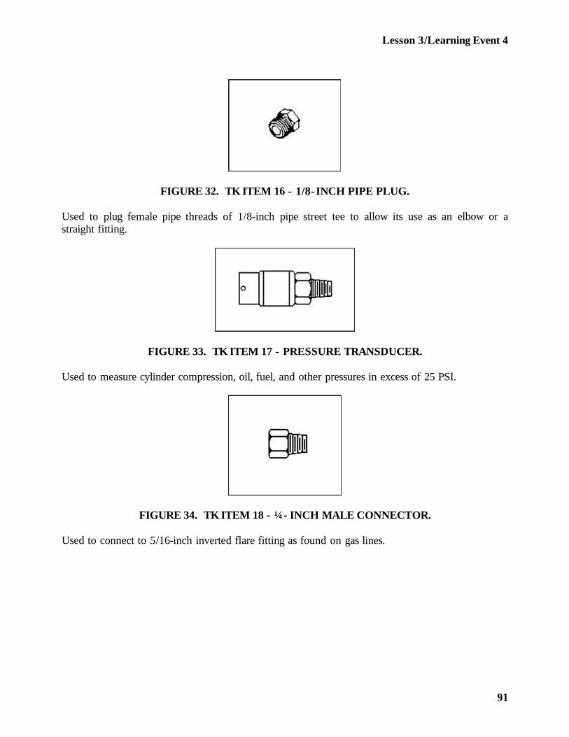
Lesson 3/Learning Event 4
FIGURE 32. TK ITEM 16 - 1/8- INCH PIPE PLUG.
Used to plug female pipe threads of 1/8-inch pipe street tee to allow its use as an elbow or astraight fitting.
FIGURE 33. TK ITEM 17 - PRESSURE TRANSDUCER.
Used to measure cylinder compression, oil, fuel, and other pressures in excess of 25 PSI.
FIGURE 34. TK ITEM 18 - ¼- INCH MALE CONNECTOR.
Used to connect to 5/16-inch inverted flare fitting as found on gas lines.
91
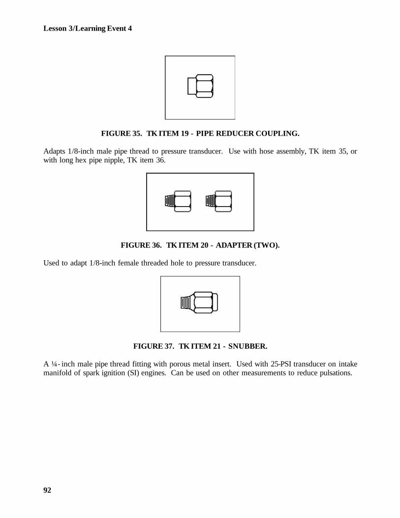
Lesson 3/Learning Event 4
FIGURE 35. TK ITEM 19 - PIPE REDUCER COUPLING.
Adapts 1/8-inch male pipe thread to pressure transducer. Use with hose assembly, TK item 35, orwith long hex pipe nipple, TK item 36.
FIGURE 36. TK ITEM 20 - ADAPTER (TWO).
Used to adapt 1/8-inch female threaded hole to pressure transducer.
FIGURE 37. TK ITEM 21 - SNUBBER.
A ¼- inch male pipe thread fitting with porous metal insert. Used with 25-PSI transducer on intakemanifold of spark ignition (SI) engines. Can be used on other measurements to reduce pulsations.
92
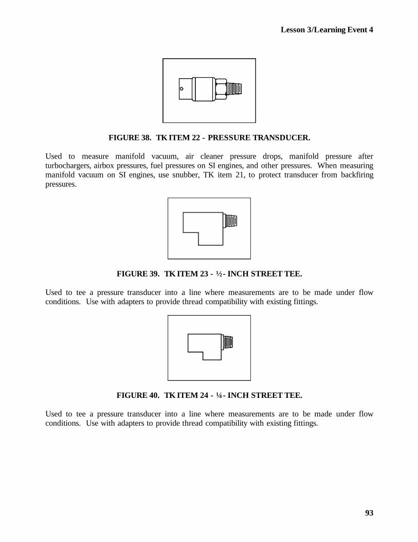
Lesson 3/Learning Event 4
FIGURE 38. TK ITEM 22 - PRESSURE TRANSDUCER.
Used to measure manifold vacuum, air cleaner pressure drops, manifold pressure afterturbochargers, airbox pressures, fuel pressures on SI engines, and other pressures. When measuringmanifold vacuum on SI engines, use snubber, TK item 21, to protect transducer from backfiringpressures.
FIGURE 39. TK ITEM 23 - ½- INCH STREET TEE.
Used to tee a pressure transducer into a line where measurements are to be made under flowconditions. Use with adapters to provide thread compatibility with existing fittings.
FIGURE 40. TK ITEM 24 - ¼- INCH STREET TEE.
Used to tee a pressure transducer into a line where measurements are to be made under flowconditions. Use with adapters to provide thread compatibility with existing fittings.
93
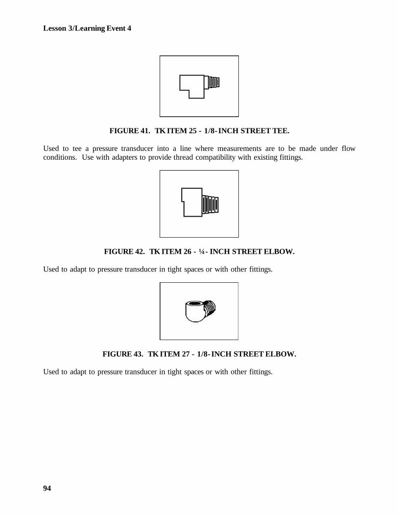
Lesson 3/Learning Event 4
FIGURE 41. TK ITEM 25 - 1/8-INCH STREET TEE.
Used to tee a pressure transducer into a line where measurements are to be made under flowconditions. Use with adapters to provide thread compatibility with existing fittings.
FIGURE 42. TK ITEM 26 - ¼- INCH STREET ELBOW.
Used to adapt to pressure transducer in tight spaces or with other fittings.
FIGURE 43. TK ITEM 27 - 1/8-INCH STREET ELBOW.
Used to adapt to pressure transducer in tight spaces or with other fittings.
94
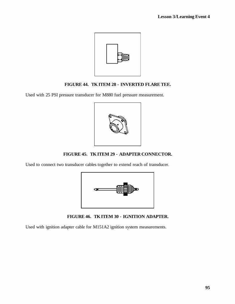
Lesson 3/Learning Event 4
FIGURE 44. TK ITEM 28 - INVERTED FLARE TEE.
Used with 25 PSI pressure transducer for M880 fuel pressure measurement.
FIGURE 45. TK ITEM 29 - ADAPTER CONNECTOR.
Used to connect two transducer cables together to extend reach of transducer.
FIGURE 46. TK ITEM 30 - IGNITION ADAPTER.
Used with ignition adapter cable for M151A2 ignition system measurements.
95
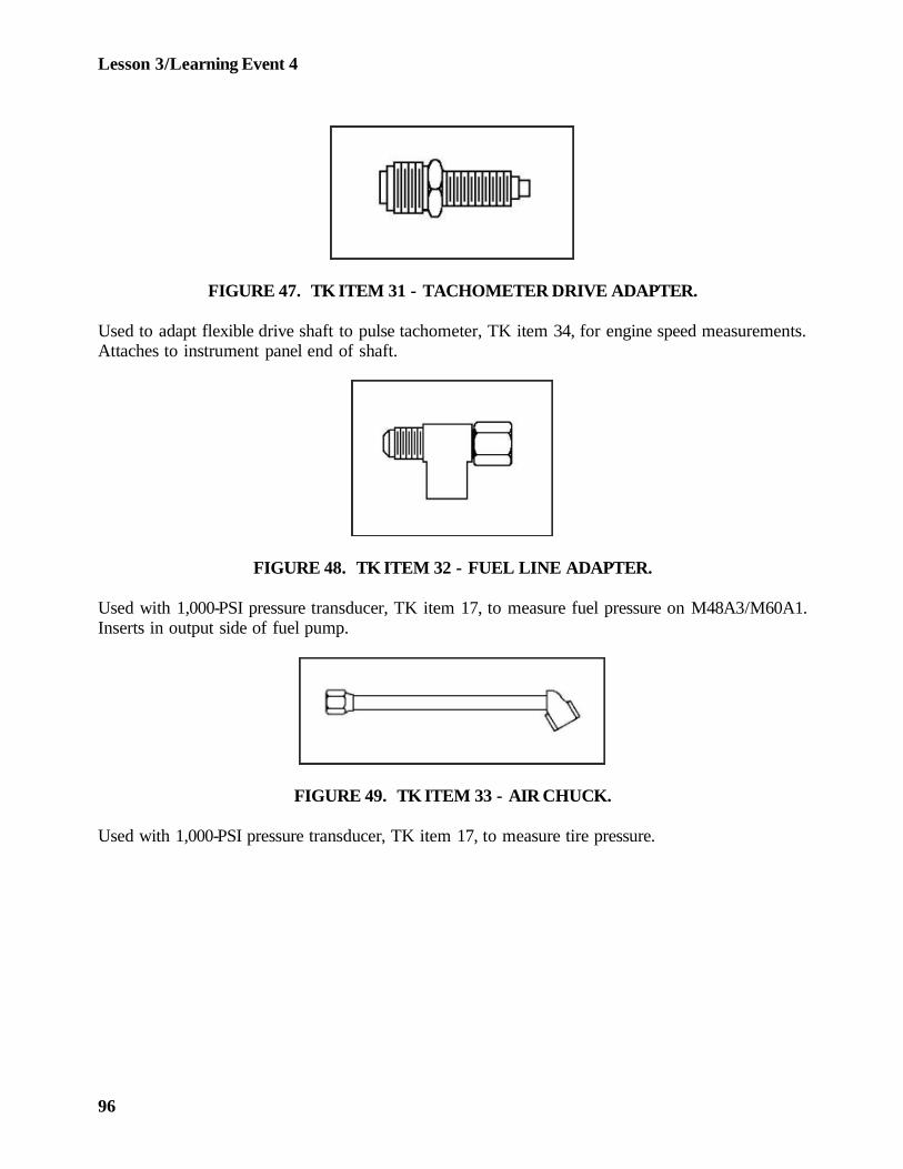
Lesson 3/Learning Event 4
FIGURE 47. TK ITEM 31 - TACHOMETER DRIVE ADAPTER.
Used to adapt flexible drive shaft to pulse tachometer, TK item 34, for engine speed measurements.Attaches to instrument panel end of shaft.
FIGURE 48. TK ITEM 32 - FUEL LINE ADAPTER.
Used with 1,000-PSI pressure transducer, TK item 17, to measure fuel pressure on M48A3/M60A1.Inserts in output side of fuel pump.
FIGURE 49. TK ITEM 33 - AIR CHUCK.
Used with 1,000-PSI pressure transducer, TK item 17, to measure tire pressure.
96
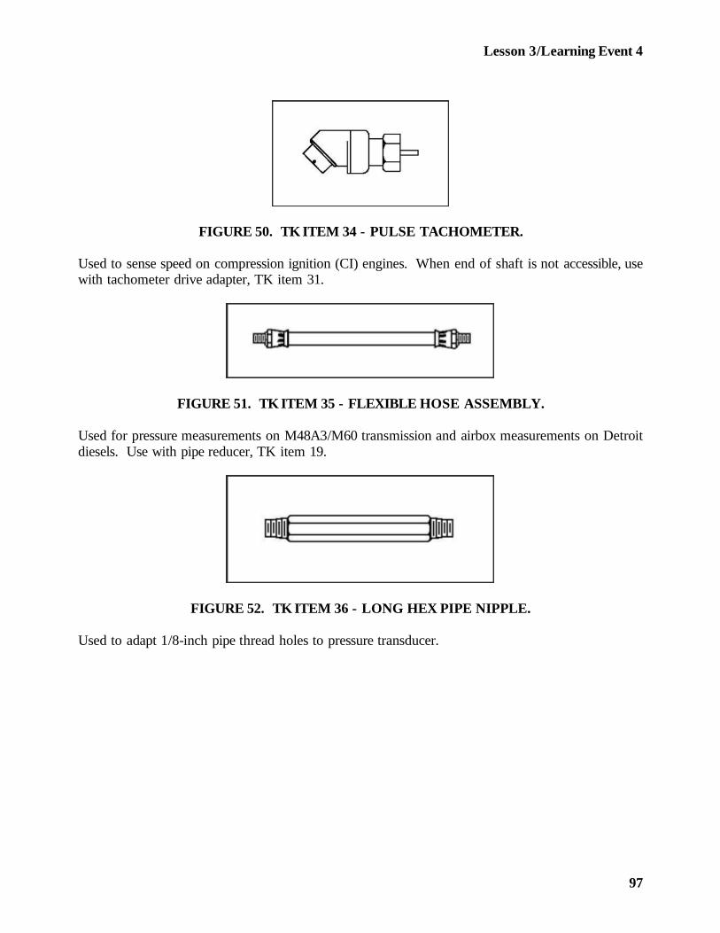
Lesson 3/Learning Event 4
FIGURE 50. TK ITEM 34 - PULSE TACHOMETER.
Used to sense speed on compression ignition (CI) engines. When end of shaft is not accessible, usewith tachometer drive adapter, TK item 31.
FIGURE 51. TK ITEM 35 - FLEXIBLE HOSE ASSEMBLY.
Used for pressure measurements on M48A3/M60 transmission and airbox measurements on Detroitdiesels. Use with pipe reducer, TK item 19.
FIGURE 52. TK ITEM 36 - LONG HEX PIPE NIPPLE.
Used to adapt 1/8-inch pipe thread holes to pressure transducer.
97
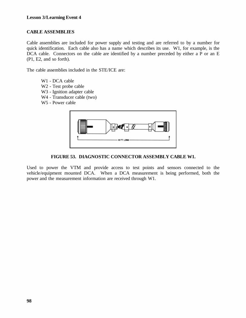
Lesson 3/Learning Event 4
CABLE ASSEMBLIES
Cable assemblies are included for power supply and testing and are referred to by a number forquick identification. Each cable also has a name which describes its use. W1, for example, is theDCA cable. Connectors on the cable are identified by a number preceded by either a P or an E(P1, E2, and so forth).
The cable assemblies included in the STE/ICE are:
W1 - DCA cableW2 - Test probe cableW3 - Ignition adapter cableW4 - Transducer cable (two)W5 - Power cable
FIGURE 53. DIAGNOSTIC CONNECTOR ASSEMBLY CABLE W1.
Used to power the VTM and provide access to test points and sensors connected to thevehicle/equipment mounted DCA. When a DCA measurement is being performed, both thepower and the measurement information are received through W1.
98

Lesson 3/Learning Event 4
FIGURE 54. TEST PROBE CABLE W2.
Used for general and special measurements. It is used for measuring voltages, frequency, resistance,and continuity; and also for the first-peak series and compression unbalance tests. W2 is dividedinto two color coded leads, red for E1 and black for E2. Test clips E1 and E2 of W2 attach topoints on the equipment being tested.
FIGURE 55. IGNITION ADAPTER CABLE W3.
Used in measuring dwell angle, points voltage, engine RPM, and power tests. W3 is divided intotwo color-coded leads; red for E1 and black for E2.
99
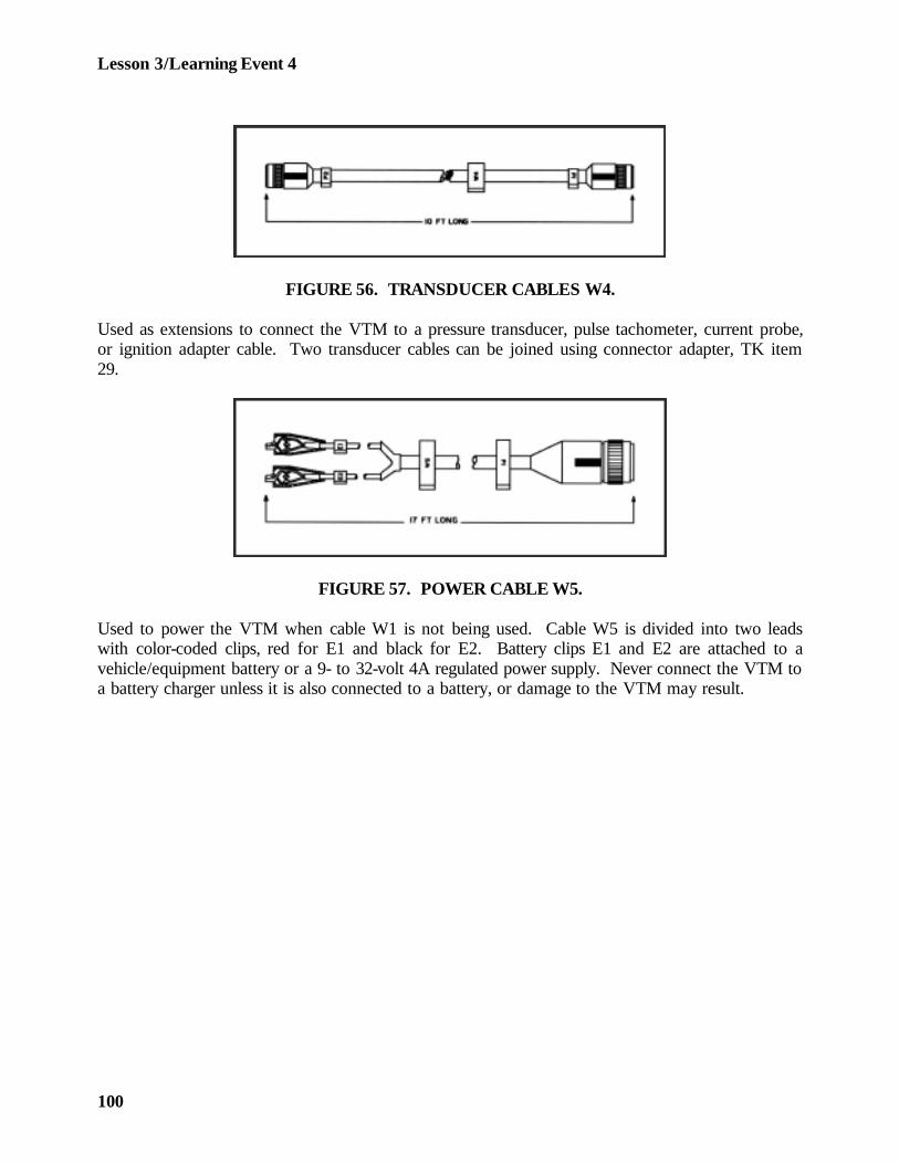
Lesson 3/Learning Event 4
FIGURE 56. TRANSDUCER CABLES W4.
Used as extensions to connect the VTM to a pressure transducer, pulse tachometer, current probe,or ignition adapter cable. Two transducer cables can be joined using connector adapter, TK item29.
FIGURE 57. POWER CABLE W5.
Used to power the VTM when cable W1 is not being used. Cable W5 is divided into two leadswith color-coded clips, red for E1 and black for E2. Battery clips E1 and E2 are attached to avehicle/equipment battery or a 9- to 32-volt 4A regulated power supply. Never connect the VTM toa battery charger unless it is also connected to a battery, or damage to the VTM may result.
100

Lesson 3/Learning Event 4
Transit Case
The STE/ICE is housed in a portable, protective transit case which contains all necessaryaccessories.
A relief vale on the front of the case allows the operator to release pressure or vacuum caused bychanges in climate during transit.
101
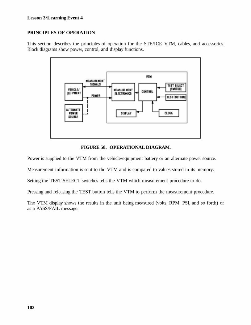
Lesson 3/Learning Event 4
PRINCIPLES OF OPERATION
This section describes the principles of operation for the STE/ICE VTM, cables, and accessories.Block diagrams show power, control, and display functions.
FIGURE 58. OPERATIONAL DIAGRAM.
Power is supplied to the VTM from the vehicle/equipment battery or an alternate power source.
Measurement information is sent to the VTM and is compared to values stored in its memory.
Setting the TEST SELECT switches tells the VTM which measurement procedure to do.
Pressing and releasing the TEST button tells the VTM to perform the measurement procedure.
The VTM display shows the results in the unit being measured (volts, RPM, PSI, and so forth) oras a PASS/FAIL message.
102
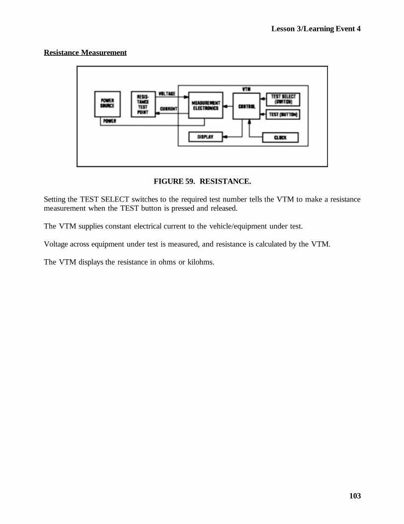
Lesson 3/Learning Event 4
Resistance Measurement
FIGURE 59. RESISTANCE.
Setting the TEST SELECT switches to the required test number tells the VTM to make a resistancemeasurement when the TEST button is pressed and released.
The VTM supplies constant electrical current to the vehicle/equipment under test.
Voltage across equipment under test is measured, and resistance is calculated by the VTM.
The VTM displays the resistance in ohms or kilohms.
103
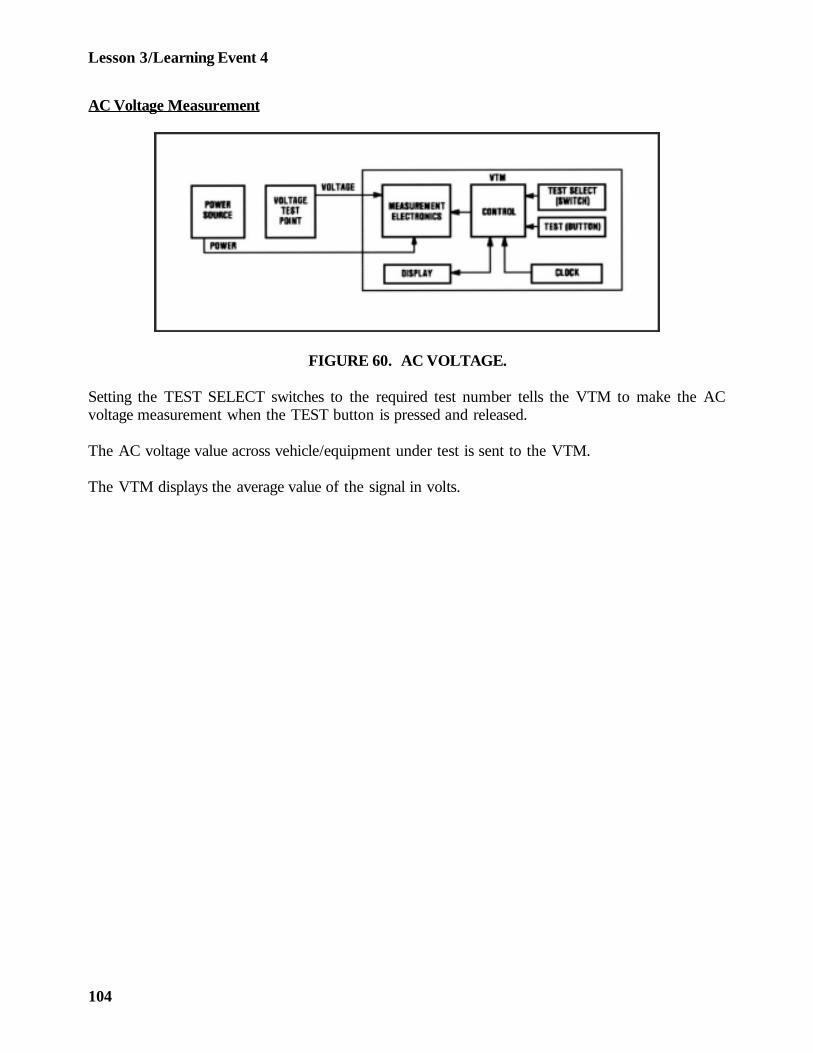
Lesson 3/Learning Event 4
AC Voltage Measurement
FIGURE 60. AC VOLTAGE.
Setting the TEST SELECT switches to the required test number tells the VTM to make the ACvoltage measurement when the TEST button is pressed and released.
The AC voltage value across vehicle/equipment under test is sent to the VTM.
The VTM displays the average value of the signal in volts.
104
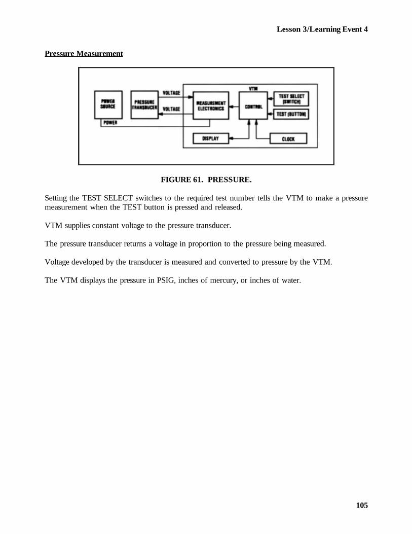
Lesson 3/Learning Event 4
Pressure Measurement
FIGURE 61. PRESSURE.
Setting the TEST SELECT switches to the required test number tells the VTM to make a pressuremeasurement when the TEST button is pressed and released.
VTM supplies constant voltage to the pressure transducer.
The pressure transducer returns a voltage in proportion to the pressure being measured.
Voltage developed by the transducer is measured and converted to pressure by the VTM.
The VTM displays the pressure in PSIG, inches of mercury, or inches of water.
105

Lesson 3/Learning Event 4
Current Measurement
FIGURE 62. CURRENT.
Setting the TEST SELECT switches to the required test number tells the VTM to make a currentmeasurement when the TEST button is pressed and released.
VTM supplies constant voltage to the current probe.
The current probe returns a voltage in proportion to the current being measured.
Voltage developed by the current probe is measured and converted to current by the VTM.
The VTM displays the current in amps.
106
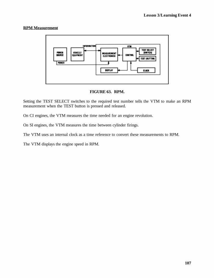
Lesson 3/Learning Event 4
RPM Measurement
FIGURE 63. RPM.
Setting the TEST SELECT switches to the required test number tells the VTM to make an RPMmeasurement when the TEST button is pressed and released.
On CI engines, the VTM measures the time needed for an engine revolution.
On SI engines, the VTM measures the time between cylinder firings.
The VTM uses an internal clock as a time reference to convert these measurements to RPM.
The VTM displays the engine speed in RPM.
107
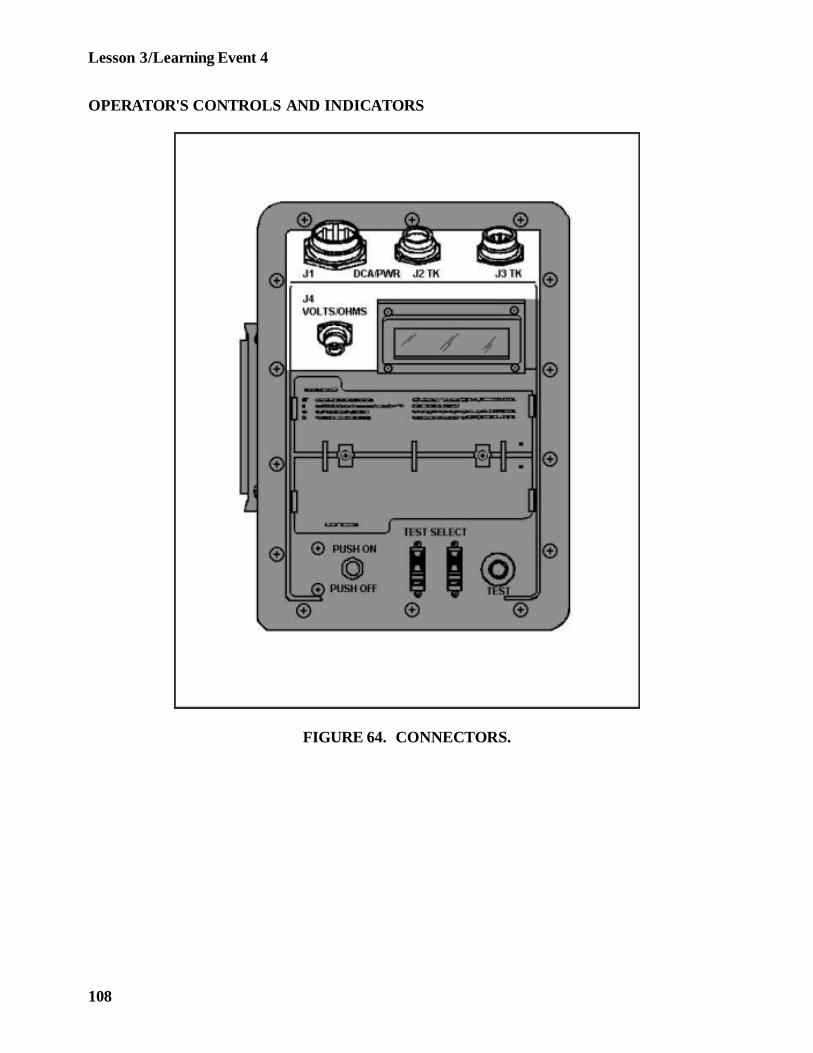
Lesson 3/Learning Event 4
OPERATOR'S CONTROLS AND INDICATORS
FIGURE 64. CONNECTORS.
108
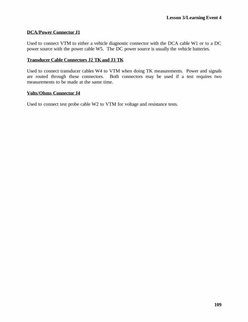
Lesson 3/Learning Event 4
DCA/Power Connector J1
Used to connect VTM to either a vehicle diagnostic connector with the DCA cable W1 or to a DCpower source with the power cable W5. The DC power source is usually the vehicle batteries.
Transducer Cable Connectors J2 TK and J3 TK
Used to connect transducer cables W4 to VTM when doing TK measurements. Power and signalsare routed through these connectors. Both connectors may be used if a test requires twomeasurements to be made at the same time.
Volts/Ohms Connector J4
Used to connect test probe cable W2 to VTM for voltage and resistance tests.
109
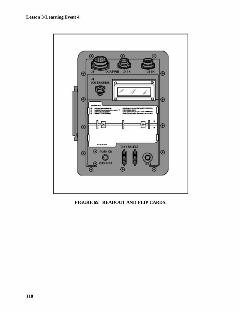
Lesson 3/Learning Event 4
FIGURE 65. READOUT AND FLIP CARDS.
110
Lesson 3/Learning Event 4
Readout Display
Displays different types of readouts during testing up to a maximum of four characters. Types ofreadouts are:
Status - keeps operator informed of what is happening, such as power applied, failed test, and soforth.
Numerical - measurement results. Units of measurement (PSI, RPM, volts, and so forth) are notdisplayed.
Error - informs operator of an error (wrong test number entered, transducer not connected, VTMfaulty, and so forth).
Flip Cards
General information to aid in testing.
111
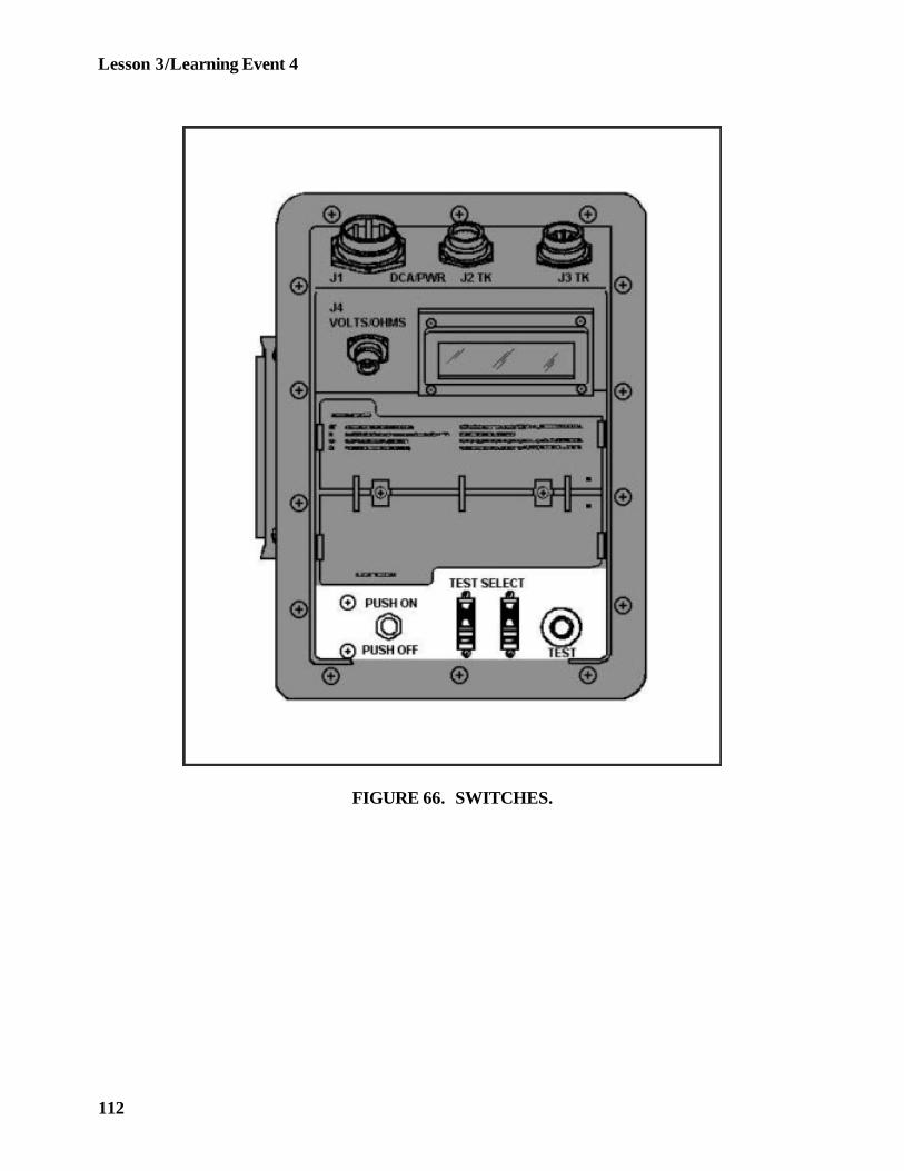
Lesson 3/Learning Event 4
FIGURE 66. SWITCHES.
112

Lesson 3/Learning Event 4
Test Button
This push-button switch has two functions:
Press and Release - causes selected test measurement to begin.
Press and Hold - initiates an offset test.
Test Select Switches
Two 10-position switches. Used to select the test to be performed by the VTM when the TESTbutton is pressed and released.
Push On/Pull Off Switch
Used to control power to the VTM from the power source. Switch contains a 4-ampere circuitbreaker to protect VTM internal circuitry.
113
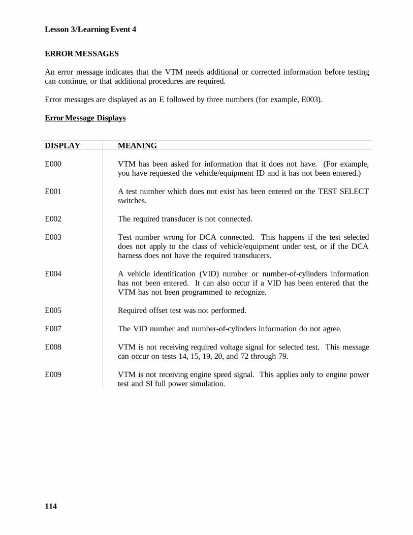
Lesson 3/Learning Event 4
ERROR MESSAGES
An error message indicates that the VTM needs additional or corrected information before testingcan continue, or that additional procedures are required.
Error messages are displayed as an E followed by three numbers (for example, E003).
Error Message Displays
DISPLAY MEANING
E000 VTM has been asked for information that it does not have. (For example,you have requested the vehicle/equipment ID and it has not been entered.)
E001 A test number which does not exist has been entered on the TEST SELECTswitches.
E002 The required transducer is not connected.
E003 Test number wrong for DCA connected. This happens if the test selecteddoes not apply to the class of vehicle/equipment under test, or if the DCAharness does not have the required transducers.
E004 A vehicle identification (VID) number or number-of-cylinders informationhas not been entered. It can also occur if a VID has been entered that theVTM has not been programmed to recognize.
E005 Required offset test was not performed.
E007 The VID number and number-of-cylinders information do not agree.
E008 VTM is not receiving required voltage signal for selected test. This messagecan occur on tests 14, 15, 19, 20, and 72 through 79.
E009 VTM is not receiving engine speed signal. This applies only to engine powertest and SI full power simulation.
114
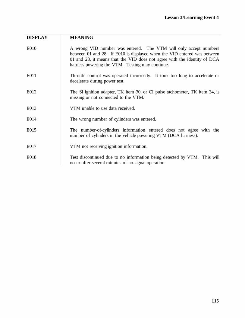
Lesson 3/Learning Event 4
DISPLAY MEANING
E010 A wrong VID number was entered. The VTM will only accept numbersbetween 01 and 28. If E010 is displayed when the VID entered was between01 and 28, it means that the VID does not agree with the identity of DCAharness powering the VTM. Testing may continue.
E011 Throttle control was operated incorrectly. It took too long to accelerate ordecelerate during power test.
E012 The SI ignition adapter, TK item 30, or CI pulse tachometer, TK item 34, ismissing or not connected to the VTM.
E013 VTM unable to use data received.
E014 The wrong number of cylinders was entered.
E015 The number-of-cylinders information entered does not agree with thenumber of cylinders in the vehicle powering VTM (DCA harness).
E017 VTM not receiving ignition information.
E018 Test discontinued due to no information being detected by VTM. This willoccur after several minutes of no-signal operation.
115
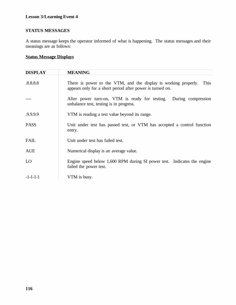
Lesson 3/Learning Event 4
STATUS MESSAGES
A status message keeps the operator informed of what is happening. The status messages and theirmeanings are as follows:
Status Message Displays
DISPLAY MEANING
.8.8.8.8 There is power to the VTM, and the display is working properly. Thisappears only for a short period after power is turned on.
---- After power turn-on, VTM is ready for testing. During compressionunbalance test, testing is in progress.
.9.9.9.9 VTM is reading a test value beyond its range.
PASS Unit under test has passed test, or VTM has accepted a control functionentry.
FAIL Unit under test has failed test.
AUE Numerical display is an average value.
LO Engine speed below 1,600 RPM during SI power test. Indicates the enginefailed the power test.
-1-1-1-1 VTM is busy.
116
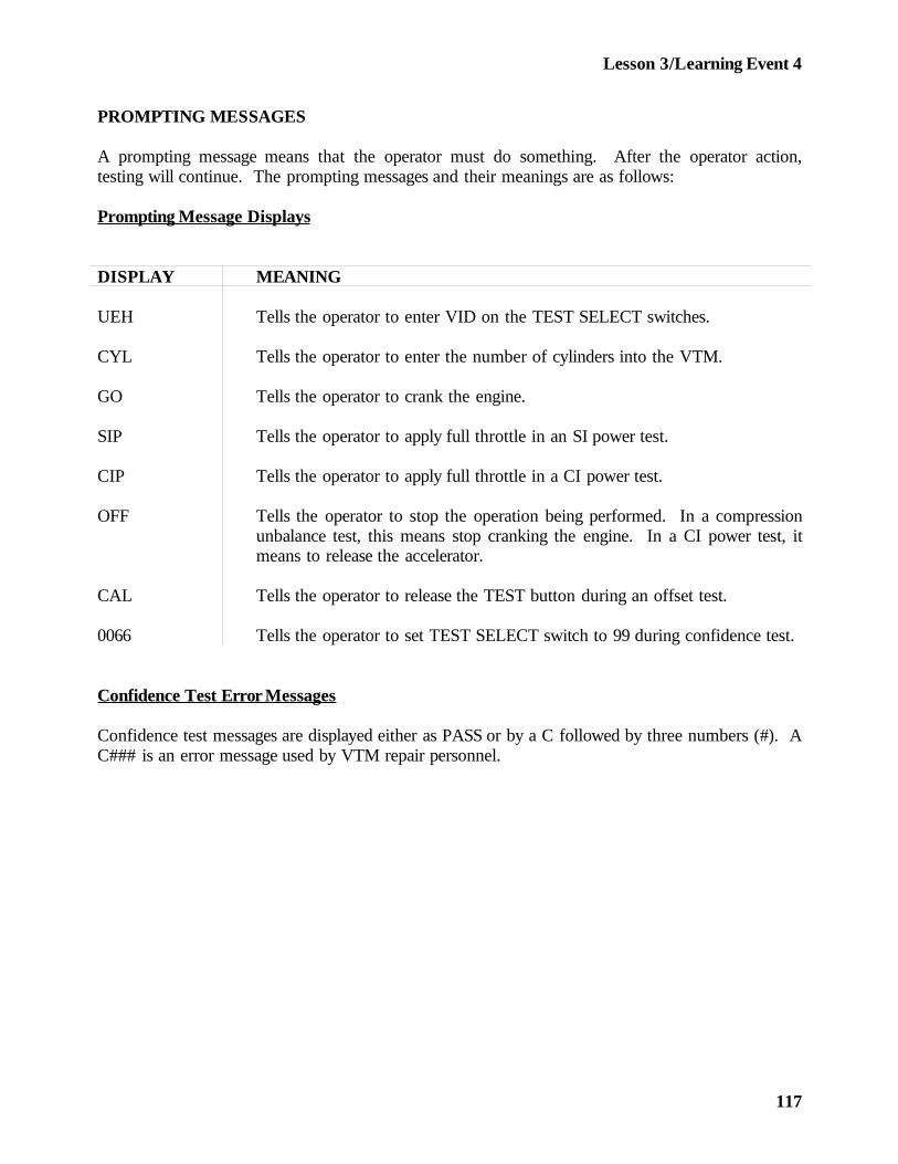
Lesson 3/Learning Event 4
PROMPTING MESSAGES
A prompting message means that the operator must do something. After the operator action,testing will continue. The prompting messages and their meanings are as follows:
Prompting Message Displays
DISPLAY MEANING
UEH Tells the operator to enter VID on the TEST SELECT switches.
CYL Tells the operator to enter the number of cylinders into the VTM.
GO Tells the operator to crank the engine.
SIP Tells the operator to apply full throttle in an SI power test.
CIP Tells the operator to apply full throttle in a CI power test.
OFF Tells the operator to stop the operation being performed. In a compressionunbalance test, this means stop cranking the engine. In a CI power test, itmeans to release the accelerator.
CAL Tells the operator to release the TEST button during an offset test.
0066 Tells the operator to set TEST SELECT switch to 99 during confidence test.
Confidence Test Error Messages
Confidence test messages are displayed either as PASS or by a C followed by three numbers (#). AC### is an error message used by VTM repair personnel.
117
Lesson 3
PRACTICE EXERCISE
1. How is a voltmeter connected into a circuit?
a. Seriesb. Parallelc. Series-parallel
2. Which meter is equipped with its own battery?
a. Voltmeterb. Ammeterc. Ohmmeter
3. Which test can be made with the multimeter that can also be made with the LVCT?
a. AC voltageb. DC voltagec. Resistance
4. The STE/ICE VTM can receive its power from
a. any 12- or 24-volt power supply.b. its own internal batteries.c. any power generator.
5. STE/ICE can be used to test
a. electrical components only.b. vehicle engines only.c. electrical and mechanical components.
118

Lesson 3
This page intentionally left blank.
119

Lesson 3
ANSWERS TO PRACTICE EXERCISE
1. b (page 66)
2. c (page 75)
3. b (page 84)
4. a (page 88)
5. c (page 88)
120