elp 7.5-10 ton heat pumps heat pump outdoor units elp
TRANSCRIPT
H E A T P U M P O U T D O O R U N I T S
ELPELITE® COMMERCIAL SPLIT SYSTEMS
R-410A - 60 HZ Bulletin No. 210805
August 2018 Supersedes April 2018
EER up to 11.07.5 to 10 Tons
Cooling Capacity - 89,000 to 115,000 BtuhHeating Capacity - 88,000 to 114,000 Btuh
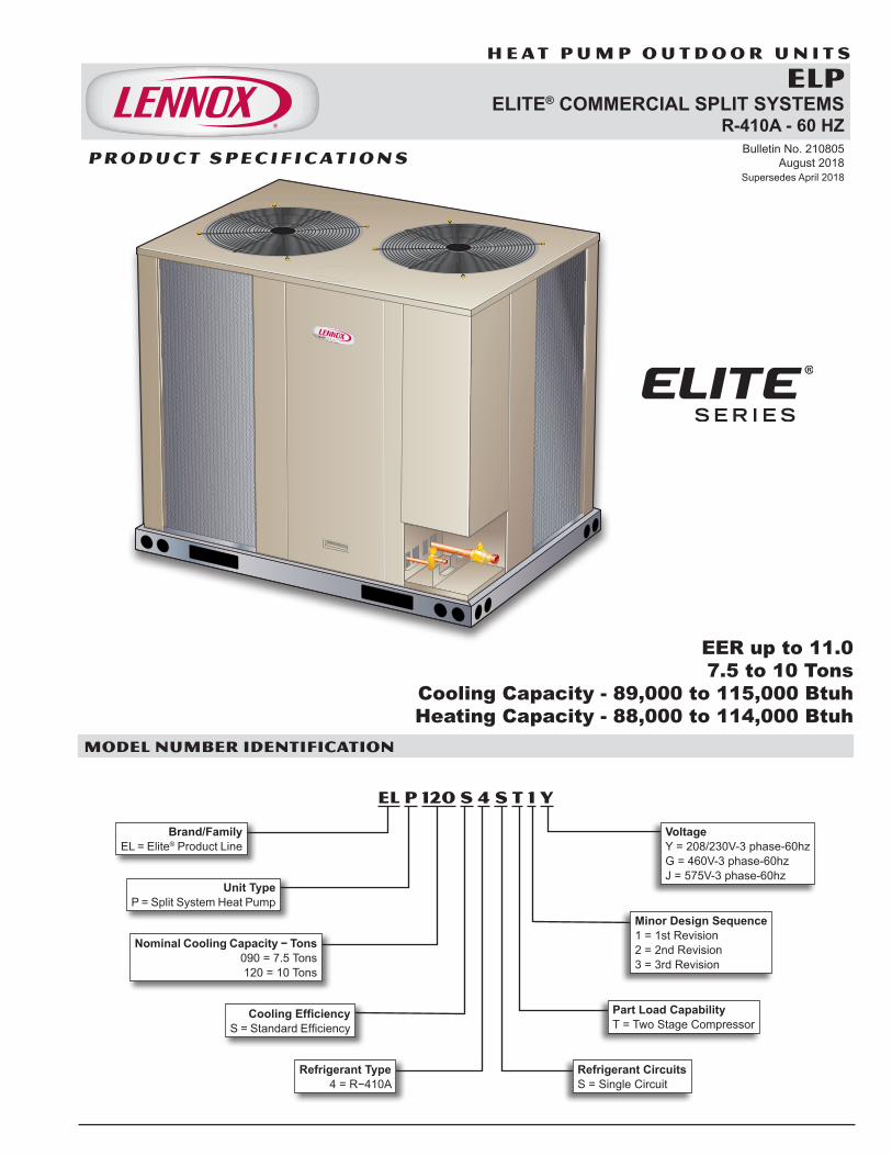
MODEL NUMBER IDENTIFICATION
EL P 120 S 4 S T 1 Y
Unit Type P = Split System Heat Pump
Cooling Efficiency S = Standard Efficiency
Minor Design Sequence 1 = 1st Revision 2 = 2nd Revision 3 = 3rd Revision
Voltage Y = 208/230V-3 phase-60hz G = 460V-3 phase-60hz J = 575V-3 phase-60hz
Nominal Cooling Capacity − Tons 090 = 7.5 Tons 120 = 10 Tons
Part Load Capability T = Two Stage Compressor
P R O D U C T S P E C I F I C AT I O N S
Refrigerant Circuits S = Single Circuit
Refrigerant Type 4 = R−410A
ELP 7.5-10 TON HEAT PUMPS
Brand/Family EL = Elite® Product Line
ELP 7.5 to 10 Ton Heat Pumps / Page 2
EQUIPMENT WARRANTY
Compressor - Limited warranty for five years in non-residential applications.All other covered components - One year in non-residential applications.Refer to Lennox Equipment Limited Warranty certificate for specific details.
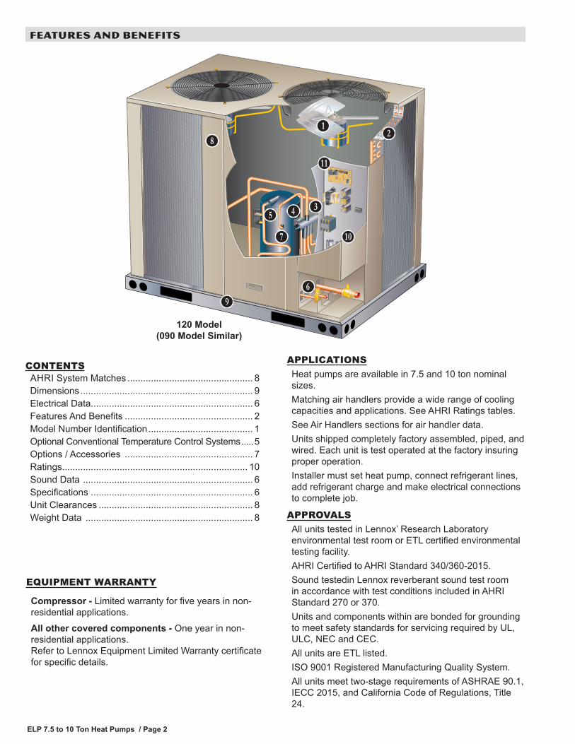
APPLICATIONSHeat pumps are available in 7.5 and 10 ton nominal sizes.Matching air handlers provide a wide range of cooling capacities and applications. See AHRI Ratings tables.See Air Handlers sections for air handler data.Units shipped completely factory assembled, piped, and wired. Each unit is test operated at the factory insuring proper operation.Installer must set heat pump, connect refrigerant lines, add refrigerant charge and make electrical connections to complete job.
APPROVALSAll units tested in Lennox’ Research Laboratory environmental test room or ETL certified environmental testing facility.AHRI Certified to AHRI Standard 340/360-2015.Sound testedin Lennox reverberant sound test room in accordance with test conditions included in AHRI Standard 270 or 370.Units and components within are bonded for grounding to meet safety standards for servicing required by UL, ULC, NEC and CEC.All units are ETL listed.ISO 9001 Registered Manufacturing Quality System.All units meet two-stage requirements of ASHRAE 90.1, IECC 2015, and California Code of Regulations, Title 24.
A
FEATURES AND BENEFITS
BC
DF E
G
H
I
J
K
120 Model (090 Model Similar)
L
CONTENTSAHRI System Matches ................................................ 8Dimensions .................................................................. 9Electrical Data.............................................................. 6Features And Benefits ................................................. 2Model Number Identification ........................................ 1Optional Conventional Temperature Control Systems .....5Options / Accessories ................................................. 7Ratings....................................................................... 10Sound Data ................................................................. 6Specifications .............................................................. 6Unit Clearances ........................................................... 8Weight Data ................................................................ 8
ELP 7.5 to 10 Ton Heat Pumps / Page 3
REFRIGERATION SYSTEMRefrigerantUnits operate with chlorine-free, ozone friendly, R-410A (field furnished).
Outdoor Coil Fan(s)Dual direct drive fan(s) moves large volumes of air uniformly through entire condenser coil(s) for high refrigerant cooling capacity.Upward discharge of air reduces operating sound levels and prevents damage to lawns, shrubs, and walkways.Fan motors are totally enclosed, overload protected and equipped with a rain shield.Fan service access is accomplished by removal of fan guards.
Copper Tube/Enhanced Fin Coil(s)ELP090S has a single “U” shaped coil.ELP120S has two “L” shaped coils.Lennox designed and fabricated coils constructed of precisely spaced ripple-edge aluminum fins machine fitted to seamless copper tubes.Lanced fins provide maximum exposure of fin surface to air stream resulting in excellent heat transfer.Fins equipped with collars that grip tubing for maximum contact area.Flared shoulder tubing connections and machine brazed silver soldering provide tight, leakproof joints.Long life copper tubing is corrosion-resistant and easy to field service.Thoroughly factory tested under high pressure to ensure leakproof construction.Completely accessible for cleaning.
Reversing ValveFactory installed 4-way reversing valve provides rapid change in refrigerant flow direction resulting in quick changeover from cooling to heating and vice-versa.Valve operates on pressure differential between outdoor unit and indoor unit.
High Pressure SwitchShuts off unit if abnormal operating conditions cause discharge pressure to rise above setting.Protects the compressor from excessive condensing pressure.Manual reset.
Loss of Charge SwitchProvides loss of charge and freeze-up protection.
Hi-Capacity Drier(s)Drier traps moisture or dirt that could contaminate the refrigerant system.
B
C
D
E
F
FEATURES AND BENEFITS
Refrigerant Lines and Service ValvesSweat connections.Fully serviceable liquid and suction line service valves provide complete service access to refrigerant system.Suction valve can be fully shut off, while liquid valve can be front seated to manage refrigerant charge while servicing system.Refrigerant lines and field wiring inlets are located in one central area of the unit cabinet.
COMPRESSORSAll models feature a single two-stage scroll compressor.Compressor features high efficiency with uniform suction flow, constant discharge flow and high volumetric efficiency and quiet operation.Compressor consists of two involute spiral scrolls matched together to generate a series of crescent shaped gas pockets between them.During compression, one scroll remains stationary while the other scroll orbits around it.Gas is drawn into the outer pocket, the pocket is sealed as the scroll rotates.As the spiral movement continues, gas pockets are pushed to the center of the scrolls. Volume between the pockets is simultaneously reduced.When pocket reaches the center, gas is now high pressure and is forced out of a port located in the center of the fixed scrolls.During compression, several pockets are compressed simultaneously resulting in a smooth continuous compression cycle.Continuous flank contact, maintained by centrifugal force, minimizes gas leakage and maximizes efficiency.Scroll compressor is tolerant to the effects of slugging and contaminants. If this occurs, scrolls separate, allowing liquid or contaminants to be worked toward the center and discharged.Low gas pulses during compression reduces operational sound levels.Compressor motor is internally protected from excessive current and temperature.Compressor is installed in the unit on resilient rubber mounts for vibration free operation.
G
H
ELP 7.5 to 10 Ton Heat Pumps / Page 4
FEATURES AND BENEFITS
COMPRESSORS (continued)
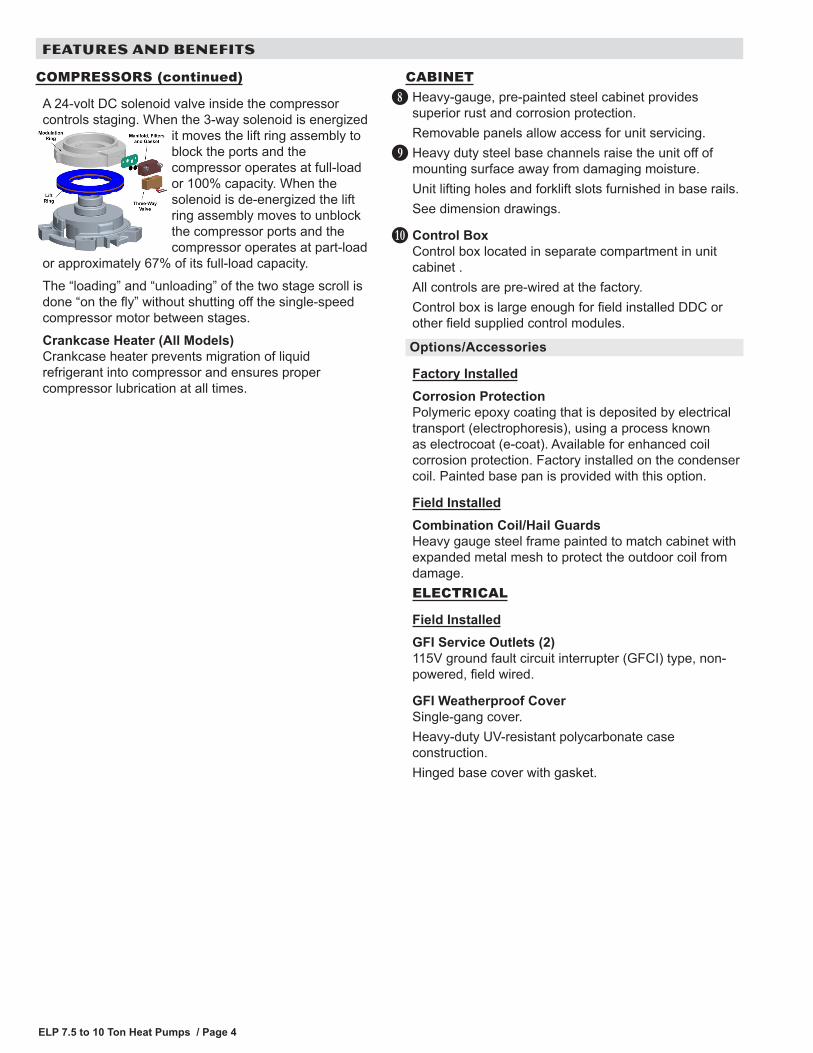
A 24-volt DC solenoid valve inside the compressor controls staging. When the 3-way solenoid is energized
it moves the lift ring assembly to block the ports and the compressor operates at full-load or 100% capacity. When the solenoid is de-energized the lift ring assembly moves to unblock the compressor ports and the compressor operates at part-load
or approximately 67% of its full-load capacity.The “loading” and “unloading” of the two stage scroll is done “on the fly” without shutting off the single-speed compressor motor between stages.Crankcase Heater (All Models)Crankcase heater prevents migration of liquid refrigerant into compressor and ensures proper compressor lubrication at all times.
CABINETHeavy-gauge, pre-painted steel cabinet provides superior rust and corrosion protection.Removable panels allow access for unit servicing.Heavy duty steel base channels raise the unit off of mounting surface away from damaging moisture.Unit lifting holes and forklift slots furnished in base rails.See dimension drawings.
Control BoxControl box located in separate compartment in unit cabinet .All controls are pre-wired at the factory.Control box is large enough for field installed DDC or other field supplied control modules.
Options/Accessories
Factory InstalledCorrosion ProtectionPolymeric epoxy coating that is deposited by electrical transport (electrophoresis), using a process known as electrocoat (e-coat). Available for enhanced coil corrosion protection. Factory installed on the condenser coil. Painted base pan is provided with this option.
Field InstalledCombination Coil/Hail GuardsHeavy gauge steel frame painted to match cabinet with expanded metal mesh to protect the outdoor coil from damage.ELECTRICAL
Field InstalledGFI Service Outlets (2)115V ground fault circuit interrupter (GFCI) type, non-powered, field wired.
GFI Weatherproof CoverSingle-gang cover.Heavy-duty UV-resistant polycarbonate case construction.Hinged base cover with gasket.
I
J
K
ELP 7.5 to 10 Ton Heat Pumps / Page 5
FEATURES AND BENEFITSCONTROLSDefrost ControlDefrost control includes the combined functions of a time/temperature defrost control, defrost relay, time delay, two diagnostic LEDs (green/red) as an aid in troubleshooting, and a terminal strip for field wiring connections.Provides a defrost cycle, if needed, every 30, 60 or 90 minutes (adjustable) of compressor “on” time at outdoor coil temperature below 42°F. Defrost thermostat mounted on outdoor coil liquid line determines defrost cycle.Built-in adjustable compressor delay can be set to allow compressor to cycle off for 30 seconds before and after a defrost cycle.Five minute timed-off delay short-cycle protection.
Options/Accessories
Field InstalledL Connection® NetworkComplete building automation control system for single or multi-zone applications. Options include local interface, software for local or remote communication, and hardware for networking other control functions.See L Connection Network Product Specifications Bulletin for details.
Network Thermostat Controller (NTC)Required for use with the L Connection Network. Monitors and controls system operation.NOTE - NTC Enclosure Kit is required for installation with the indoor unit and must be ordered extra.
L
NTC Enclosure KitRequired for mounting the Network Thermostat Controller external to the indoor unit.Mounted on the supply air end of the ELA air handler cabinet.Consists of a box and cover constructed of sheet metal (unpainted).Two openings for field wiring to the unit.Dimensions (L x W x H): 10-1/2 x 8-1/8 x 3-7/8 in. (267 x 203 x 98 mm).
Low Ambient ControlHeat pumps will operate satisfactorily in cooling mode down to 45°F outdoor air temperature without any additional controls.Low Ambient Control Kit can be field installed, allowing unit operation down to 0°F using pressure-regulated fan speed control.
Indoor Air Quality (CO2) SensorsMonitors CO2 levels, reports which adjusts economizer dampers as needed.
ThermostatThermostat is not furnished with unit and must be ordered extra.See page 6, also see individual Thermostat bulletins and Lennox Price Book.
Aftermarket Unit Controller OptionsSee Options/Accessories table for selection.
ELP 7.5 to 10 Ton Heat Pumps / Page 6
OPTIONAL CONVENTIONAL TEMPERATURE CONTROL SYSTEMS
Item Model No.
Catalog No.
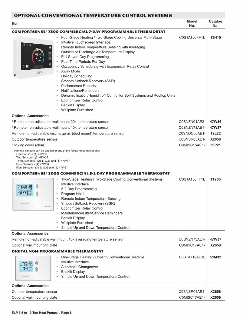
COMFORTSENSE® 7500 COMMERCIAL 7-DAY PROGRAMMABLE THERMOSTAT
• Four-Stage Heating / Two-Stage Cooling Universal Multi-Stage• Intuitive Touchscreen Interface• Remote Indoor Temperature Sensing with Averaging• Outside or Discharge Air Temperature Display• Full Seven-Day Programming• Four Time Periods Per Day• Occupancy Scheduling with Economizer Relay Control• Away Mode• Holiday Scheduling• Smooth Setback Recovery (SSR)• Performance Reports• Notifications/Reminders• Dehumidification/Humiditrol® Control for Split Systems and Rooftop Units• Economizer Relay Control• Backlit Display• Wallplate Furnished
C0STAT06FF1L 13H15
Optional Accessories1 Remote non-adjustable wall mount 20k temperature sensor C0SNZN01AE2- 47W361 Remote non-adjustable wall mount 10k temperature sensor C0SNZN73AE1- 47W37Remote non-adjustable discharge air (duct mount) temperature sensor C0SNDC00AE1- 19L22Outdoor temperature sensor C0SNSR03AE1- X2658Locking cover (clear) C0MISC15AE1- 39P211 R emote sensors can be applied in any of the following combinations:
One Sensor - (1) 47W36 Two Sensors - (2) 47W37 Three Sensors - (2) 47W36 and (1) 47W37 Four Sensors - (4) 47W36 Five Sensors - (3) 47W36 and (2) 47W37
COMFORTSENSE® 3000 COMMERCIAL 5-2 DAY PROGRAMMABLE THERMOSTAT
MAINT
Commercial
• Two-Stage Heating / Two-Stage Cooling Conventional Systems• Intuitive Interface• 5-2 Day Programming• Program Hold• Remote Indoor Temperature Sensing• Smooth Setback Recovery (SSR)• Economizer Relay Control• Maintenance/Filter/Service Reminders• Backlit Display• Wallplate Furnished• Simple Up and Down Temperature Control.
C0STAT05FF1L 11Y05
Optional AccessoriesRemote non-adjustable wall mount 10k averaging temperature sensor C0SNZN73AE1- 47W37Optional wall mounting plate C0MISC17AE1- X2659DIGITAL NON-PROGRAMMABLE THERMOSTAT
• One-Stage Heating / Cooling Conventional Systems• Intuitive Interface• Automatic Changeover• Backlit Display• Simple Up and Down Temperature Control.
C0STAT12AE1L 51M32
Optional AccessoriesOutdoor temperature sensor C0SNSR04AE1- X2658Optional wall mounting plate C0MISC17AE1- X2659
ELP 7.5 to 10 Ton Heat Pumps / Page 7
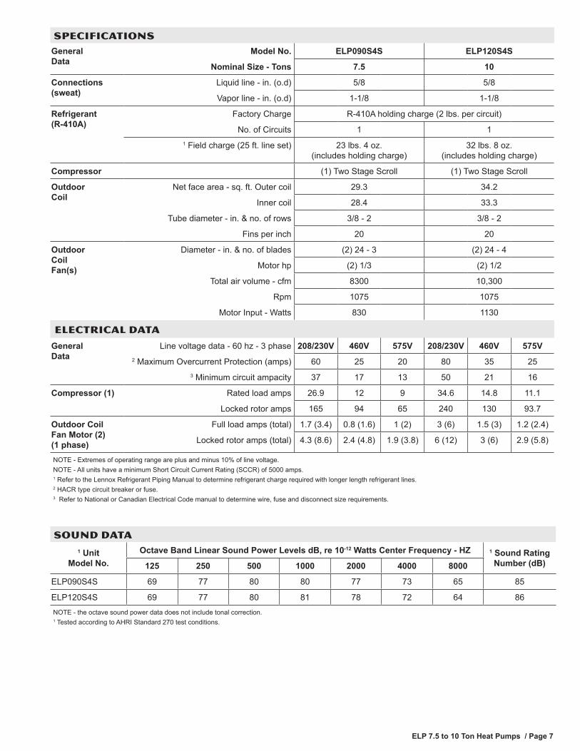
SPECIFICATIONS General Data
Model No. ELP090S4S ELP120S4S
Nominal Size - Tons 7.5 10
Connections (sweat)
Liquid line - in. (o.d) 5/8 5/8
Vapor line - in. (o.d) 1-1/8 1-1/8
Refrigerant (R-410A)
Factory Charge R-410A holding charge (2 lbs. per circuit)
No. of Circuits 1 11 Field charge (25 ft. line set) 23 lbs. 4 oz.
(includes holding charge)32 lbs. 8 oz.
(includes holding charge)
Compressor (1) Two Stage Scroll (1) Two Stage Scroll
Outdoor Coil
Net face area - sq. ft. Outer coil 29.3 34.2
Inner coil 28.4 33.3
Tube diameter - in. & no. of rows 3/8 - 2 3/8 - 2
Fins per inch 20 20
Outdoor Coil Fan(s)
Diameter - in. & no. of blades (2) 24 - 3 (2) 24 - 4
Motor hp (2) 1/3 (2) 1/2
Total air volume - cfm 8300 10,300
Rpm 1075 1075
Motor Input - Watts 830 1130
ELECTRICAL DATA
General Data
Line voltage data - 60 hz - 3 phase 208/230V 460V 575V 208/230V 460V 575V2 Maximum Overcurrent Protection (amps) 60 25 20 80 35 25
3 Minimum circuit ampacity 37 17 13 50 21 16
Compressor (1) Rated load amps 26.9 12 9 34.6 14.8 11.1
Locked rotor amps 165 94 65 240 130 93.7
Outdoor Coil Fan Motor (2) (1 phase)
Full load amps (total) 1.7 (3.4) 0.8 (1.6) 1 (2) 3 (6) 1.5 (3) 1.2 (2.4)
Locked rotor amps (total) 4.3 (8.6) 2.4 (4.8) 1.9 (3.8) 6 (12) 3 (6) 2.9 (5.8)
NOTE - Extremes of operating range are plus and minus 10% of line voltage.NOTE - All units have a minimum Short Circuit Current Rating (SCCR) of 5000 amps.1 Refer to the Lennox Refrigerant Piping Manual to determine refrigerant charge required with longer length refrigerant lines.2 HACR type circuit breaker or fuse.3 Refer to National or Canadian Electrical Code manual to determine wire, fuse and disconnect size requirements.
SOUND DATA 1 Unit
Model No.Octave Band Linear Sound Power Levels dB, re 10-12 Watts Center Frequency - HZ 1 Sound Rating
Number (dB)125 250 500 1000 2000 4000 8000
ELP090S4S 69 77 80 80 77 73 65 85
ELP120S4S 69 77 80 81 78 72 64 86NOTE - the octave sound power data does not include tonal correction.1 Tested according to AHRI Standard 270 test conditions.
ELP 7.5 to 10 Ton Heat Pumps / Page 8
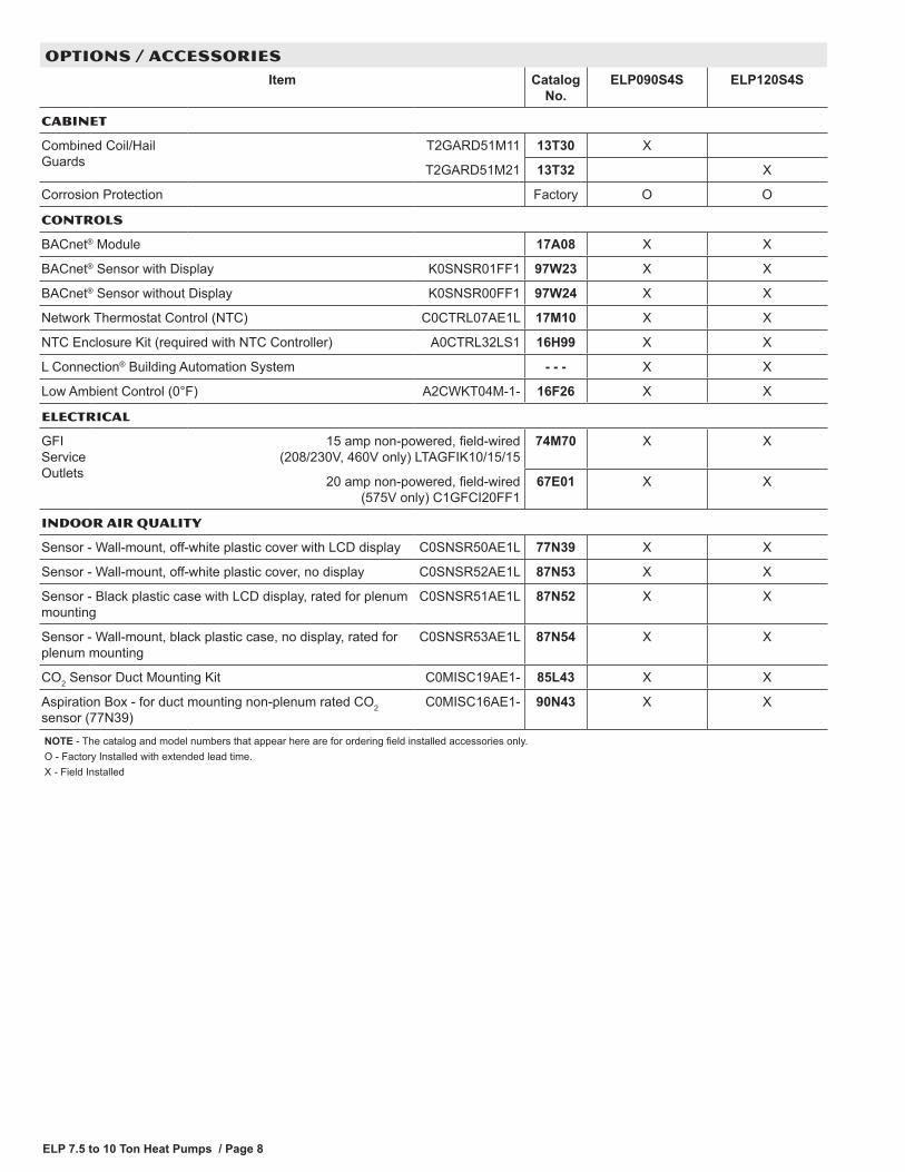
OPTIONS / ACCESSORIES Item Catalog
No.ELP090S4S ELP120S4S
CABINET
Combined Coil/Hail Guards
T2GARD51M11 13T30 X
T2GARD51M21 13T32 X
Corrosion Protection Factory O O
CONTROLS
BACnet® Module 17A08 X X
BACnet® Sensor with Display K0SNSR01FF1 97W23 X X
BACnet® Sensor without Display K0SNSR00FF1 97W24 X X
Network Thermostat Control (NTC) C0CTRL07AE1L 17M10 X X
NTC Enclosure Kit (required with NTC Controller) A0CTRL32LS1 16H99 X X
L Connection® Building Automation System - - - X X
Low Ambient Control (0°F) A2CWKT04M-1- 16F26 X X
ELECTRICAL
GFI Service Outlets
15 amp non-powered, field-wired (208/230V, 460V only) LTAGFIK10/15/15
74M70 X X
20 amp non-powered, field-wired (575V only) C1GFCI20FF1
67E01 X X
INDOOR AIR QUALITY
Sensor - Wall-mount, off-white plastic cover with LCD display C0SNSR50AE1L 77N39 X X
Sensor - Wall-mount, off-white plastic cover, no display C0SNSR52AE1L 87N53 X X
Sensor - Black plastic case with LCD display, rated for plenum mounting
C0SNSR51AE1L 87N52 X X
Sensor - Wall-mount, black plastic case, no display, rated for plenum mounting
C0SNSR53AE1L 87N54 X X
CO2 Sensor Duct Mounting Kit C0MISC19AE1- 85L43 X X
Aspiration Box - for duct mounting non-plenum rated CO2 sensor (77N39)
C0MISC16AE1- 90N43 X X
NOTE - The catalog and model numbers that appear here are for ordering field installed accessories only.O - Factory Installed with extended lead time.X - Field Installed
ELP 7.5 to 10 Ton Heat Pumps / Page 9
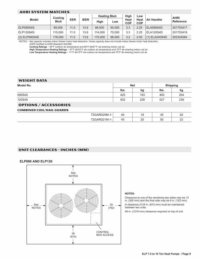
AHRI SYSTEM MATCHES
Model Cooling Btuh EER IEER
Heating Btuh High Heat COP
Low Heat COP
Air Handler AHRIReferenceHigh Low
ELP090S4S 89,000 11.0 13.6 88,000 50,000 3.3 2.25 ELA090S4D 201753417ELP120S4S 115,000 11.0 13.6 114,000 70,000 3.3 2.25 ELA120S4D 201753418(2) ELP090S4S 178,000 11.0 13.6 170,000 98,000 3.2 2.05 (1) ELA240S4D 202324584NOTES − Net capacity includes indoor blower motor heat deduction. Gross capacity does not include indoor blower motor heat deduction.
AHRI Certified to AHRI Standard 340/360: Cooling Ratings − 95 °F outdoor air temperature and 80° F db/67 °F wb entering indoor coil air. High Temperature Heating Ratings − 47° F db/43° F wb outdoor air temperature and 70 °F db entering indoor coil air. Low Temperature Heating Ratings − 17 °F db/15 °F wb outdoor air temperature and 70 °F db entering indoor coil air.
WEIGHT DATA Model No. Net Shipping
lbs. kg lbs. kg090S4S 425 193 450 204120S4S 502 228 527 239
OPTIONS / ACCESSORIESCOMBINED COIL/HAIL GUARDS
T2GARD20M-1- 40 18 45 20T2GARD21M-1- 45 20 50 23
ELP090 AND ELP120
CONTROLBOX ACCESS
30(762)
SeeNOTES
36(914)
SeeNOTES
NOTES:Clearance to one of the remaining two sides may be 12in. (305 mm) and the final side may be 6 in. (152 mm).A clearance of 24 in. (610 mm) must be maintainedbetween two units.48 in. (1219 mm) clearance required on top of unit.
UNIT CLEARANCES - INCHES (MM)
ELP 7.5 to 10 Ton Heat Pumps / Page 10
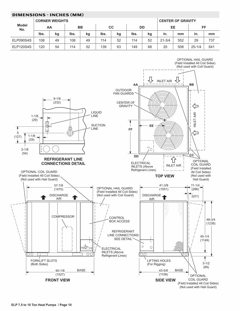
Model No.
CORNER WEIGHTS CENTER OF GRAVITY
AA BB CC DD EE FF
lbs. kg lbs. kg lbs. kg lbs. kg in. mm in. mm
ELP090S4S 108 49 108 49 114 52 114 52 21-3/4 552 29 737
ELP120S4S 120 54 114 52 139 63 149 68 20 508 25-1/4 641
9-1/8(232)
1-1/8(29)
2-1/8(54)
SUCTIONLINE
LIQUIDLINE
REFRIGERANT LINECONNECTIONS DETAIL
1-1/8(29)
5(127)
BASE
REFRIGERANTLINE CONNECTIONS
SEE DETAIL
DISCHARGEAIR
41-3/8(1051)
60-1/8(1527)
57-7/8(1470)
CONTROLBOX ACCESS
COMPRESSOR
DISCHARGEAIR
LIFTING HOLES(For Rigging)
FRONT VIEW
TOP VIEW
FORKLIFT SLOTS(Both Sides)
SIDE VIEW
43-5/8(1108)
48-3/4(1238)
3-1/2(89)
45-1/4(1149)
FFEE IN
LET
AIR
INLET AIR
BBAA
CCDD
CENTER OFGRAVITY
ELECTRICALINLETS (AboveRefrigerant Lines)
OUTDOORFAN GUARDS
INLET AIR
BASE
ELECTRICAL INLETS (Above Refrigerant Lines)
OPTIONAL HAIL GUARD(Field Installed All Coil Sides)(Not used with Coil Guard)
OPTIONAL HAIL GUARD(Field Installed All Coil Sides)
(Not used with Coil Guard)
OPTIONALCOIL GUARD
(Field Installed All Coil Sides)(Not used with Hail Guard)
2(51)
11-1/4(286)
(Not used withHail Guard)
OPTIONAL COIL GUARD(Field Installed All Coil Sides)
(Not used with Hail Guard)
OPTIONALCOIL GUARD(Field InstalledAll Coil Sides)
DIMENSIONS - INCHES (MM)
ELP 7.5 to 10 Ton Heat Pumps / Page 11
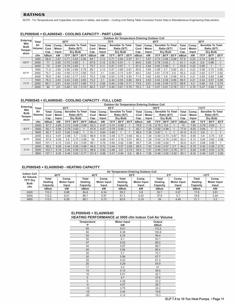
RATINGSNOTE - For Temperatures and Capacities not shown in tables, see bulletin - Cooling Unit Rating Table Correction Factor Data in Miscellaneous Engineering Data section.
ELP090S4S + ELA090S4D - COOLING CAPACITY - FULL LOADEntering
Wet Bulb
Temper-ature
Total Air
Volume
Outdoor Air Temperature Entering Outdoor Coil85°F 95°F 105°F 115°F
Total Cool Cap.
Comp. Motor Input
Sensible To Total Ratio (S/T)
Total Cool Cap.
Comp. Motor Input
Sensible To Total Ratio (S/T)
Total Cool Cap.
Comp. Motor Input
Sensible To Total Ratio (S/T)
Total Cool Cap.
Comp. Motor Input
Sensible To Total Ratio (S/T)
Dry Bulb Dry Bulb Dry Bulb Dry Bulbcfm kBtuh kW 75°F 80°F 85°F kBtuh kW 75°F 80°F 85°F kBtuh kW 75°F 80°F 85°F kBtuh kW 75°F 80°F 85°F
63°F2400 87.7 5.85 0.72 0.86 0.98 83.3 6.47 0.74 0.88 1 78.8 7.16 0.75 0.9 1 74 7.93 0.78 0.93 13000 92.1 5.94 0.78 0.93 1 87.8 6.57 0.79 0.95 1 82.7 7.26 0.82 0.98 1 77.8 8.03 0.84 1 13600 95.7 6.01 0.82 0.98 1 91.1 6.64 0.85 1 1 86.5 7.35 0.87 1 1 81.9 8.13 0.9 1 1
67°F2400 93.3 5.97 0.58 0.7 0.82 88.8 6.59 0.58 0.71 0.84 84.2 7.29 0.59 0.73 0.87 78.9 8.06 0.6 0.75 0.93000 97.8 6.06 0.6 0.75 0.89 93 6.69 0.61 0.76 0.91 88.2 7.39 0.62 0.79 0.94 82.4 8.15 0.64 0.82 0.983600 101.1 6.13 0.63 0.8 0.95 96.1 6.76 0.65 0.82 0.98 90.7 7.45 0.66 0.84 1 84.9 8.21 0.68 0.88 1
71°F2400 99.2 6.09 0.44 0.56 0.68 94.5 6.72 0.44 0.57 0.69 89.5 7.42 0.45 0.57 0.7 84.2 8.19 0.45 0.59 0.733000 103.7 6.18 0.45 0.59 0.72 98.8 6.82 0.46 0.6 0.74 93.4 7.51 0.46 0.61 0.76 87.7 8.28 0.46 0.63 0.793600 107.1 6.25 0.46 0.62 0.77 101.9 6.88 0.47 0.64 0.8 96.4 7.58 0.48 0.65 0.82 90.1 8.34 0.49 0.67 0.85
ELP090S4S + ELA090S4D - HEATING CAPACITY
Indoor Coil Air Volume
70°F Dry Bulb cfm
Air Temperature Entering Outdoor Coil65°F 45°F 25°F 5°F -15°F
Total Heating Capacity
Comp. Motor Input
Input
Total Heating Capacity
Comp. Motor Input
Input
Total Heating Capacity
Comp. Motor Input
Input
Total Heating Capacity
Comp. Motor Input
Input
Total Heating Capacity
Comp. Motor Input
InputkBtuh kW kBtuh kW kBtuh kW kBtuh kW kBtuh kW
2400 110.2 6.88 84.8 6.34 59.3 5.8 35.7 5.07 17.8 3.813000 112.2 6.51 86.7 5.97 61.3 5.43 37.6 4.7 19.8 3.443600 113.5 6.28 88.1 5.73 62.6 5.19 39 4.46 21.1 3.2
ELP090S4S + ELA090S4D HEATING PERFORMANCE at 3000 cfm Indoor Coil Air Volume
Temperature °F
Motor Input kW
Output kBtuh
65 6.51 112.260 6.38 105.855 6.24 99.450 6.1 93.147 6.02 89.345 5.97 86.740 5.84 80.435 5.7 74.130 5.56 67.725 5.43 61.320 5.29 54.917 5.2 5115 5.15 48.510 5.01 42.15 4.7 37.60 4.38 33.2-5 4.07 28.7
-10 3.75 24.2-15 3.44 19.8-20 3.12 15.3
ELP090S4S + ELA090S4D - COOLING CAPACITY - PART LOADEntering
Wet Bulb
Temper-ature
Total Air
Volume
Outdoor Air Temperature Entering Outdoor Coil65°F 75°F 85°F 95°F
Total Cool Cap.
Comp. Motor Input
Sensible To Total Ratio (S/T)
Total Cool Cap.
Comp. Motor Input
Sensible To Total Ratio (S/T)
Total Cool Cap.
Comp. Motor Input
Sensible To Total Ratio (S/T)
Total Cool Cap.
Comp. Motor Input
Sensible To Total Ratio (S/T)
Dry Bulb Dry Bulb Dry Bulb Dry Bulbcfm kBtuh kW 75°F 80°F 85°F kBtuh kW 75°F 80°F 85°F kBtuh kW 75°F 80°F 85°F kBtuh kW 75°F 80°F 85°F
63°F1600 66.9 2.67 0.71 0.83 0.95 64.1 3.14 0.71 0.84 0.97 61.1 3.67 0.73 0.86 0.99 57.9 4.25 0.74 0.89 12000 71 2.65 0.75 0.89 1 67.9 3.12 0.76 0.91 1 64.6 3.65 0.78 0.93 1 61.1 4.24 0.8 0.96 12400 74 2.64 0.79 0.95 1 70.7 3.11 0.81 0.97 1 67.2 3.64 0.83 0.99 1 63.8 4.22 0.85 1 1
67°F1600 71.5 2.65 0.56 0.68 0.79 68.7 3.12 0.57 0.69 0.81 65.6 3.65 0.58 0.7 0.82 62.1 4.23 0.58 0.72 0.852000 75.7 2.63 0.59 0.73 0.85 72.5 3.1 0.59 0.73 0.87 69.2 3.63 0.61 0.75 0.9 65.5 4.22 0.62 0.77 0.922400 78.9 2.62 0.62 0.77 0.91 75.3 3.09 0.63 0.78 0.93 71.5 3.62 0.63 0.8 0.96 67.6 4.21 0.65 0.83 0.98
71°F1600 76.3 2.63 0.44 0.55 0.65 73.2 3.1 0.44 0.55 0.66 69.9 3.63 0.44 0.56 0.68 66.5 4.21 0.44 0.57 0.692000 80.7 2.61 0.45 0.57 0.69 77.3 3.08 0.45 0.58 0.71 73.8 3.61 0.46 0.59 0.73 69.9 4.2 0.46 0.6 0.742400 84 2.6 0.46 0.6 0.74 80.3 3.07 0.46 0.61 0.76 76.3 3.6 0.47 0.61 0.78 72.1 4.19 0.47 0.64 0.8
ELP 7.5 to 10 Ton Heat Pumps / Page 12
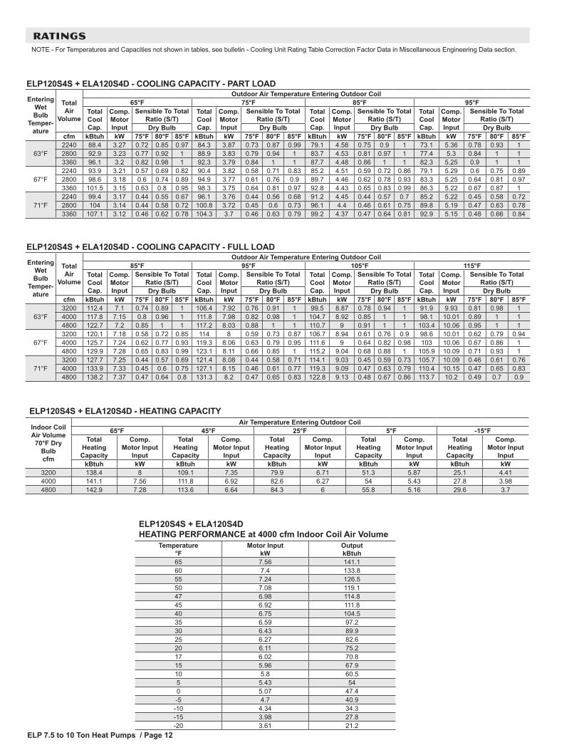
RATINGSNOTE - For Temperatures and Capacities not shown in tables, see bulletin - Cooling Unit Rating Table Correction Factor Data in Miscellaneous Engineering Data section.
ELP120S4S + ELA120S4D - COOLING CAPACITY - FULL LOADEntering
Wet Bulb
Temper-ature
Total Air
Volume
Outdoor Air Temperature Entering Outdoor Coil85°F 95°F 105°F 115°F
Total Cool Cap.
Comp. Motor Input
Sensible To Total Ratio (S/T)
Total Cool Cap.
Comp. Motor Input
Sensible To Total Ratio (S/T)
Total Cool Cap.
Comp. Motor Input
Sensible To Total Ratio (S/T)
Total Cool Cap.
Comp. Motor Input
Sensible To Total Ratio (S/T)
Dry Bulb Dry Bulb Dry Bulb Dry Bulbcfm kBtuh kW 75°F 80°F 85°F kBtuh kW 75°F 80°F 85°F kBtuh kW 75°F 80°F 85°F kBtuh kW 75°F 80°F 85°F
63°F3200 112.4 7.1 0.74 0.89 1 106.4 7.92 0.76 0.91 1 99.5 8.87 0.78 0.94 1 91.9 9.93 0.81 0.98 14000 117.8 7.15 0.8 0.96 1 111.8 7.98 0.82 0.98 1 104.7 8.92 0.85 1 1 98.1 10.01 0.89 1 14800 122.7 7.2 0.85 1 1 117.2 8.03 0.88 1 1 110.7 9 0.91 1 1 103.4 10.06 0.95 1 1
67°F3200 120.1 7.18 0.58 0.72 0.85 114 8 0.59 0.73 0.87 106.7 8.94 0.61 0.76 0.9 98.6 10.01 0.62 0.79 0.944000 125.7 7.24 0.62 0.77 0.93 119.3 8.06 0.63 0.79 0.95 111.6 9 0.64 0.82 0.98 103 10.06 0.67 0.86 14800 129.9 7.28 0.65 0.83 0.99 123.1 8.11 0.66 0.85 1 115.2 9.04 0.68 0.88 1 105.9 10.09 0.71 0.93 1
71°F3200 127.7 7.25 0.44 0.57 0.69 121.4 8.08 0.44 0.58 0.71 114.1 9.03 0.45 0.59 0.73 105.7 10.09 0.46 0.61 0.764000 133.9 7.33 0.45 0.6 0.75 127.1 8.15 0.46 0.61 0.77 119.3 9.09 0.47 0.63 0.79 110.4 10.15 0.47 0.65 0.834800 138.2 7.37 0.47 0.64 0.8 131.3 8.2 0.47 0.65 0.83 122.8 9.13 0.48 0.67 0.86 113.7 10.2 0.49 0.7 0.9
ELP120S4S + ELA120S4D - HEATING CAPACITY
Indoor Coil Air Volume
70°F Dry Bulb cfm
Air Temperature Entering Outdoor Coil65°F 45°F 25°F 5°F -15°F
Total Heating Capacity
Comp. Motor Input
Input
Total Heating Capacity
Comp. Motor Input
Input
Total Heating Capacity
Comp. Motor Input
Input
Total Heating Capacity
Comp. Motor Input
Input
Total Heating Capacity
Comp. Motor Input
InputkBtuh kW kBtuh kW kBtuh kW kBtuh kW kBtuh kW
3200 138.4 8 109.1 7.35 79.9 6.71 51.3 5.87 25.1 4.414000 141.1 7.56 111.8 6.92 82.6 6.27 54 5.43 27.8 3.984800 142.9 7.28 113.6 6.64 84.3 6 55.8 5.16 29.6 3.7
ELP120S4S + ELA120S4D HEATING PERFORMANCE at 4000 cfm Indoor Coil Air Volume
Temperature °F
Motor Input kW
Output kBtuh
65 7.56 141.160 7.4 133.855 7.24 126.550 7.08 119.147 6.98 114.845 6.92 111.840 6.75 104.535 6.59 97.230 6.43 89.925 6.27 82.620 6.11 75.217 6.02 70.815 5.96 67.910 5.8 60.55 5.43 540 5.07 47.4-5 4.7 40.9
-10 4.34 34.3-15 3.98 27.8-20 3.61 21.2
ELP120S4S + ELA120S4D - COOLING CAPACITY - PART LOADEntering
Wet Bulb
Temper-ature
Total Air
Volume
Outdoor Air Temperature Entering Outdoor Coil65°F 75°F 85°F 95°F
Total Cool Cap.
Comp. Motor Input
Sensible To Total Ratio (S/T)
Total Cool Cap.
Comp. Motor Input
Sensible To Total Ratio (S/T)
Total Cool Cap.
Comp. Motor Input
Sensible To Total Ratio (S/T)
Total Cool Cap.
Comp. Motor Input
Sensible To Total Ratio (S/T)
Dry Bulb Dry Bulb Dry Bulb Dry Bulbcfm kBtuh kW 75°F 80°F 85°F kBtuh kW 75°F 80°F 85°F kBtuh kW 75°F 80°F 85°F kBtuh kW 75°F 80°F 85°F
63°F2240 88.4 3.27 0.72 0.85 0.97 84.3 3.87 0.73 0.87 0.99 79.1 4.58 0.75 0.9 1 73.1 5.36 0.78 0.93 12800 92.9 3.23 0.77 0.92 1 88.9 3.83 0.79 0.94 1 83.7 4.53 0.81 0.97 1 77.4 5.3 0.84 1 13360 96.1 3.2 0.82 0.98 1 92.3 3.79 0.84 1 1 87.7 4.48 0.86 1 1 82.3 5.25 0.9 1 1
67°F2240 93.9 3.21 0.57 0.69 0.82 90.4 3.82 0.58 0.71 0.83 85.2 4.51 0.59 0.72 0.86 79.1 5.29 0.6 0.75 0.892800 98.6 3.18 0.6 0.74 0.89 94.9 3.77 0.61 0.76 0.9 89.7 4.46 0.62 0.78 0.93 83.3 5.25 0.64 0.81 0.973360 101.5 3.15 0.63 0.8 0.95 98.3 3.75 0.64 0.81 0.97 92.8 4.43 0.65 0.83 0.99 86.3 5.22 0.67 0.87 1
71°F2240 99.4 3.17 0.44 0.55 0.67 96.1 3.76 0.44 0.56 0.68 91.2 4.45 0.44 0.57 0.7 85.2 5.22 0.45 0.58 0.722800 104 3.14 0.44 0.58 0.72 100.8 3.72 0.45 0.6 0.73 96.1 4.4 0.46 0.61 0.75 89.8 5.19 0.47 0.63 0.783360 107.1 3.12 0.46 0.62 0.78 104.3 3.7 0.46 0.63 0.79 99.2 4.37 0.47 0.64 0.81 92.9 5.15 0.48 0.66 0.84
ELP 7.5 to 10 Ton Heat Pumps / Page 13
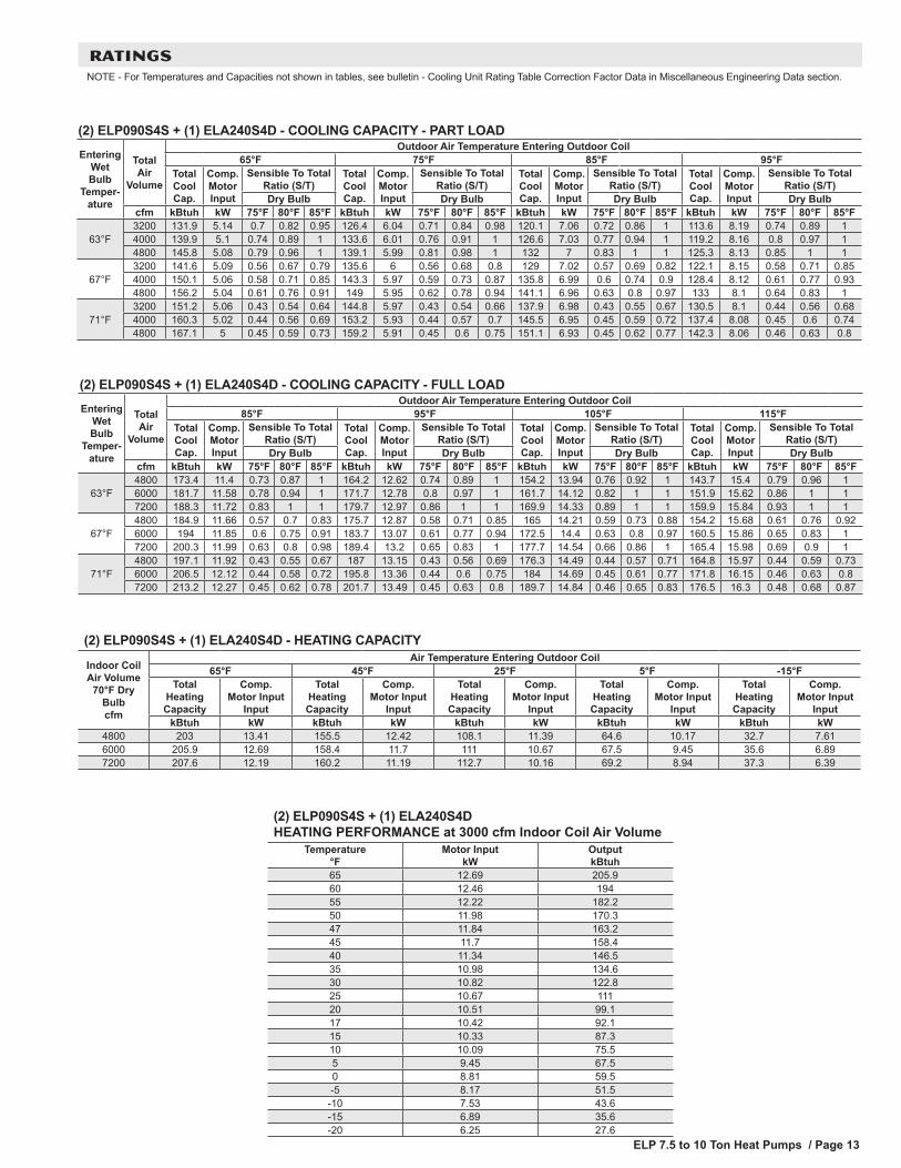
RATINGSNOTE - For Temperatures and Capacities not shown in tables, see bulletin - Cooling Unit Rating Table Correction Factor Data in Miscellaneous Engineering Data section.
(2) ELP090S4S + (1) ELA240S4D - COOLING CAPACITY - FULL LOADEntering
Wet Bulb
Temper-ature
Total Air
Volume
Outdoor Air Temperature Entering Outdoor Coil85°F 95°F 105°F 115°F
Total Cool Cap.
Comp. Motor Input
Sensible To Total Ratio (S/T)
Total Cool Cap.
Comp. Motor Input
Sensible To Total Ratio (S/T)
Total Cool Cap.
Comp. Motor Input
Sensible To Total Ratio (S/T)
Total Cool Cap.
Comp. Motor Input
Sensible To Total Ratio (S/T)
Dry Bulb Dry Bulb Dry Bulb Dry Bulbcfm kBtuh kW 75°F 80°F 85°F kBtuh kW 75°F 80°F 85°F kBtuh kW 75°F 80°F 85°F kBtuh kW 75°F 80°F 85°F
63°F4800 173.4 11.4 0.73 0.87 1 164.2 12.62 0.74 0.89 1 154.2 13.94 0.76 0.92 1 143.7 15.4 0.79 0.96 16000 181.7 11.58 0.78 0.94 1 171.7 12.78 0.8 0.97 1 161.7 14.12 0.82 1 1 151.9 15.62 0.86 1 17200 188.3 11.72 0.83 1 1 179.7 12.97 0.86 1 1 169.9 14.33 0.89 1 1 159.9 15.84 0.93 1 1
67°F4800 184.9 11.66 0.57 0.7 0.83 175.7 12.87 0.58 0.71 0.85 165 14.21 0.59 0.73 0.88 154.2 15.68 0.61 0.76 0.926000 194 11.85 0.6 0.75 0.91 183.7 13.07 0.61 0.77 0.94 172.5 14.4 0.63 0.8 0.97 160.5 15.86 0.65 0.83 17200 200.3 11.99 0.63 0.8 0.98 189.4 13.2 0.65 0.83 1 177.7 14.54 0.66 0.86 1 165.4 15.98 0.69 0.9 1
71°F4800 197.1 11.92 0.43 0.55 0.67 187 13.15 0.43 0.56 0.69 176.3 14.49 0.44 0.57 0.71 164.8 15.97 0.44 0.59 0.736000 206.5 12.12 0.44 0.58 0.72 195.8 13.36 0.44 0.6 0.75 184 14.69 0.45 0.61 0.77 171.8 16.15 0.46 0.63 0.87200 213.2 12.27 0.45 0.62 0.78 201.7 13.49 0.45 0.63 0.8 189.7 14.84 0.46 0.65 0.83 176.5 16.3 0.48 0.68 0.87
(2) ELP090S4S + (1) ELA240S4D - HEATING CAPACITY
Indoor Coil Air Volume
70°F Dry Bulb cfm
Air Temperature Entering Outdoor Coil65°F 45°F 25°F 5°F -15°F
Total Heating Capacity
Comp. Motor Input
Input
Total Heating Capacity
Comp. Motor Input
Input
Total Heating Capacity
Comp. Motor Input
Input
Total Heating Capacity
Comp. Motor Input
Input
Total Heating Capacity
Comp. Motor Input
InputkBtuh kW kBtuh kW kBtuh kW kBtuh kW kBtuh kW
4800 203 13.41 155.5 12.42 108.1 11.39 64.6 10.17 32.7 7.616000 205.9 12.69 158.4 11.7 111 10.67 67.5 9.45 35.6 6.897200 207.6 12.19 160.2 11.19 112.7 10.16 69.2 8.94 37.3 6.39
(2) ELP090S4S + (1) ELA240S4D HEATING PERFORMANCE at 3000 cfm Indoor Coil Air Volume
Temperature °F
Motor Input kW
Output kBtuh
65 12.69 205.960 12.46 19455 12.22 182.250 11.98 170.347 11.84 163.245 11.7 158.440 11.34 146.535 10.98 134.630 10.82 122.825 10.67 11120 10.51 99.117 10.42 92.115 10.33 87.310 10.09 75.55 9.45 67.50 8.81 59.5-5 8.17 51.5
-10 7.53 43.6-15 6.89 35.6-20 6.25 27.6
(2) ELP090S4S + (1) ELA240S4D - COOLING CAPACITY - PART LOADEntering
Wet Bulb
Temper-ature
Total Air
Volume
Outdoor Air Temperature Entering Outdoor Coil65°F 75°F 85°F 95°F
Total Cool Cap.
Comp. Motor Input
Sensible To Total Ratio (S/T)
Total Cool Cap.
Comp. Motor Input
Sensible To Total Ratio (S/T)
Total Cool Cap.
Comp. Motor Input
Sensible To Total Ratio (S/T)
Total Cool Cap.
Comp. Motor Input
Sensible To Total Ratio (S/T)
Dry Bulb Dry Bulb Dry Bulb Dry Bulbcfm kBtuh kW 75°F 80°F 85°F kBtuh kW 75°F 80°F 85°F kBtuh kW 75°F 80°F 85°F kBtuh kW 75°F 80°F 85°F
63°F3200 131.9 5.14 0.7 0.82 0.95 126.4 6.04 0.71 0.84 0.98 120.1 7.06 0.72 0.86 1 113.6 8.19 0.74 0.89 14000 139.9 5.1 0.74 0.89 1 133.6 6.01 0.76 0.91 1 126.6 7.03 0.77 0.94 1 119.2 8.16 0.8 0.97 14800 145.8 5.08 0.79 0.96 1 139.1 5.99 0.81 0.98 1 132 7 0.83 1 1 125.3 8.13 0.85 1 1
67°F3200 141.6 5.09 0.56 0.67 0.79 135.6 6 0.56 0.68 0.8 129 7.02 0.57 0.69 0.82 122.1 8.15 0.58 0.71 0.854000 150.1 5.06 0.58 0.71 0.85 143.3 5.97 0.59 0.73 0.87 135.8 6.99 0.6 0.74 0.9 128.4 8.12 0.61 0.77 0.934800 156.2 5.04 0.61 0.76 0.91 149 5.95 0.62 0.78 0.94 141.1 6.96 0.63 0.8 0.97 133 8.1 0.64 0.83 1
71°F3200 151.2 5.06 0.43 0.54 0.64 144.8 5.97 0.43 0.54 0.66 137.9 6.98 0.43 0.55 0.67 130.5 8.1 0.44 0.56 0.684000 160.3 5.02 0.44 0.56 0.69 153.2 5.93 0.44 0.57 0.7 145.5 6.95 0.45 0.59 0.72 137.4 8.08 0.45 0.6 0.744800 167.1 5 0.45 0.59 0.73 159.2 5.91 0.45 0.6 0.75 151.1 6.93 0.45 0.62 0.77 142.3 8.06 0.46 0.63 0.8


REVISIONS
REVISIONS
Sections Description of Change
AHRI System Matches Additional match added.
Rating Tables Additional match added.
NOTE - Due to Lennox’ ongoing commitment to quality, Specifications, Ratings and Dimensions subject to change without notice and without incurring liability. Improper installation, adjustment, alteration, service or maintenance can cause property damage or personal injury. Installation and service must be performed by a qualified installer and servicing agency. ©2018 Lennox Industries, Inc.
Visit us at www.lennox.com For the latest technical information, www.lennoxcommercial.com Contact us at 1-800-4-LENNOX