em200 aem cord connector - encision · the aem endoshield ® 2 burn protection system uses aem ®...
TRANSCRIPT
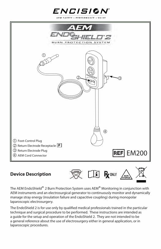
Device Description
The AEM EndoShield® 2 Burn Protection System uses AEM® Monitoring in conjunction with AEM instruments and an electrosurgical generator to continuously monitor and dynamically manage stray energy (insulation failure and capacitive coupling) during monopolar laparoscopic electrosurgery.
The EndoShield 2 is for use only by qualified medical professionals trained in the particular technique and surgical procedure to be performed. These instructions are intended as a guide for the setup and operation of the EndoShield 2. They are not intended to be a general reference about the use of electrosurgery either in general application, or in laparoscopic procedures.
EM200
Foot-Control Plug
Return Electrode Receptacle
Return Electrode Plug
AEM Cord Connector
2 of 51
WARNING: These devices have been specifically designed for use in electrosurgery. Do not use for other procedures.
Caution: The EndoShield 2 is designed to safely deliver electrosurgical energy and to prevent injury caused by insulation failure and capacitive coupling. The EndoShield 2 is not intended to test for insulation damage on laparoscopic instruments. Do not attempt to use this system as an instrument inspection tool.
Prior to using the EndoShield 2, read and review these instructions, the instructions for use for the electrosurgical generator, and the instructions for use for all instruments and accessories to be used.
Warnings and Cautions start on page 15
EndoShield 2 3 of 51
Table of Contents
How AEM ® Monitoring Works. . . . . . . . . . . . . . . . . . . 4
System Setup . . . . . . . . . . . . . . . . . . . . . . . . . . . 5
At End of Life . . . . . . . . . . . . . . . . . . . . . . . . . . . 9
Removing the Battery . . . . . . . . . . . . . . . . . . . . 9
End of Life Indicators . . . . . . . . . . . . . . . . . . . . . 10
Reprocessing . . . . . . . . . . . . . . . . . . . . . . . . . 10
Compatible Products . . . . . . . . . . . . . . . . . . . . . . . 10
Electrosurgical Generator . . . . . . . . . . . . . . . . . . 10
Return Electrode . . . . . . . . . . . . . . . . . . . . . . . 10
Active Electrode . . . . . . . . . . . . . . . . . . . . . . . 10
Instrument Cord . . . . . . . . . . . . . . . . . . . . . . . 10
Encision Adapter . . . . . . . . . . . . . . . . . . . . . . . 11
Troubleshooting and System Maintenance . . . . . . . . . . . . 12
Mechanical Inspection . . . . . . . . . . . . . . . . . . . . 12
Correcting Setup Faults . . . . . . . . . . . . . . . . . . . . 12
Responding to the EndoShield 2 Alarms . . . . . . . . . . . 13
Cleaning the EndoShield 2 . . . . . . . . . . . . . . . . . . 14
Storing the EndoShield 2 . . . . . . . . . . . . . . . . . . . 14
Warnings and Cautions . . . . . . . . . . . . . . . . . . . . . . 15
Technical Specifications . . . . . . . . . . . . . . . . . . . . . . 17
Limited Warranty . . . . . . . . . . . . . . . . . . . . . . . . . 22
Symbol Definitions . . . . . . . . . . . . . . . . . . . . . . . . 24
Indications for UseThe EndoShield 2 is an accessory for use with electrosurgical generators and AEM instruments that is designed to safely deliver electrosurgical energy and to prevent injury caused by insulation failure and capacitive coupling.
Active electrode monitoring is intended to control stray monopolar energy caused by insulation failure and capacitive coupling in surgical instruments on the shaft of the instrument.
ContraindicationsThere are no known contraindications for the use of the EndoShield 2.
4 of 51
How AEM® Monitoring Works
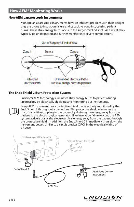
Non-AEM Laparoscopic InstrumentsMonopolar laparoscopic instruments have an inherent problem with their design; they are prone to insulation failure and capacitive coupling, causing patient burns. These stray energy burns occur in the surgeon’s blind spot. As a result, they typically go undiagnosed and further manifest into severe complications.
The EndoShield 2 Burn Protection SystemEncision’s AEM technology eliminates stray energy burns to patients during laparoscopy by electrically shielding and monitoring our instruments.Every AEM instrument has a protective shield that is actively monitored by the EndoShield 2 throughout a procedure. This protective shield eliminates the risk of capacitive coupling to the patient by draining the energy away from the patient to the electrosurgical generator. If an insulation failure occurs, the AEM system actively drains the electrosurgical energy away from the patient through the protective shield. In addition, the EndoShield 2 immediately shuts down the instrument power, similar to a circuit breaker (GFCI) in the electrical wiring of a house.
Patient Return Electrode
Electrosurgical Generator
EndoShield 2 AEM Foot-Control Instrument
AEM Cord
EndoShield 2 5 of 51
How AEM® Monitoring Works (continued)
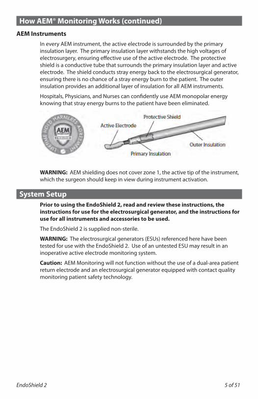
AEM InstrumentsIn every AEM instrument, the active electrode is surrounded by the primary insulation layer. The primary insulation layer withstands the high voltages of electrosurgery, ensuring effective use of the active electrode. The protective shield is a conductive tube that surrounds the primary insulation layer and active electrode. The shield conducts stray energy back to the electrosurgical generator, ensuring there is no chance of a stray energy burn to the patient. The outer insulation provides an additional layer of insulation for all AEM instruments.
Hospitals, Physicians, and Nurses can confidently use AEM monopolar energy knowing that stray energy burns to the patient have been eliminated.
WARNING: AEM shielding does not cover zone 1, the active tip of the instrument, which the surgeon should keep in view during instrument activation.
System Setup Prior to using the EndoShield 2, read and review these instructions, the
instructions for use for the electrosurgical generator, and the instructions for use for all instruments and accessories to be used.
The EndoShield 2 is supplied non-sterile.
WARNING: The electrosurgical generators (ESUs) referenced here have been tested for use with the EndoShield 2. Use of an untested ESU may result in an inoperative active electrode monitoring system.
Caution: AEM Monitoring will not function without the use of a dual-area patient return electrode and an electrosurgical generator equipped with contact quality monitoring patient safety technology.
6 of 51
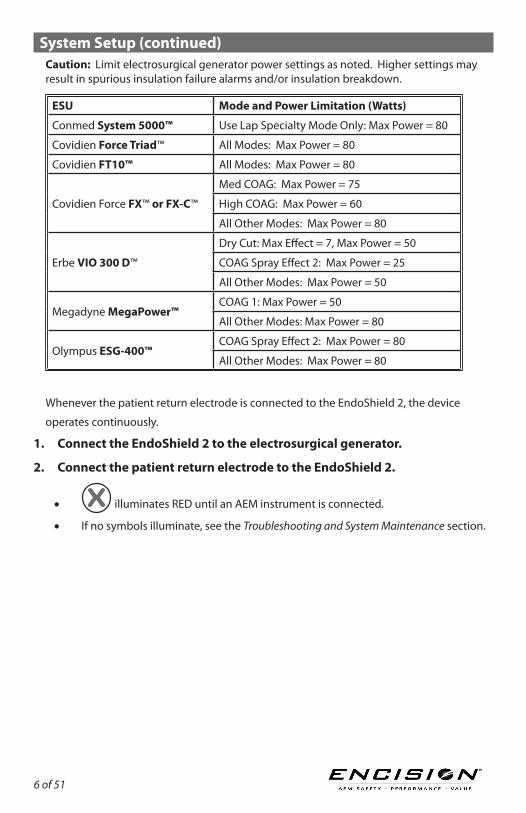
System Setup (continued)Caution: Limit electrosurgical generator power settings as noted. Higher settings may result in spurious insulation failure alarms and/or insulation breakdown.
ESU Mode and Power Limitation (Watts)
Conmed System 5000™ Use Lap Specialty Mode Only: Max Power = 80
Covidien Force Triad™ All Modes: Max Power = 80
Covidien FT10™ All Modes: Max Power = 80
Covidien Force FX™ or FX-C™
Med COAG: Max Power = 75
High COAG: Max Power = 60
All Other Modes: Max Power = 80
Erbe VIO 300 D™
Dry Cut: Max Effect = 7, Max Power = 50
COAG Spray Effect 2: Max Power = 25
All Other Modes: Max Power = 50
Megadyne MegaPower™COAG 1: Max Power = 50
All Other Modes: Max Power = 80
Olympus ESG-400™COAG Spray Effect 2: Max Power = 80
All Other Modes: Max Power = 80
Whenever the patient return electrode is connected to the EndoShield 2, the device
operates continuously.System Setup (continued)1. Connect the EndoShield 2 to the electrosurgical generator.
2. Connect the patient return electrode to the EndoShield 2.
• illuminates RED until an AEM instrument is connected.
• If no symbols illuminate, see the Troubleshooting and System Maintenance section.
EndoShield 2 7 of 51
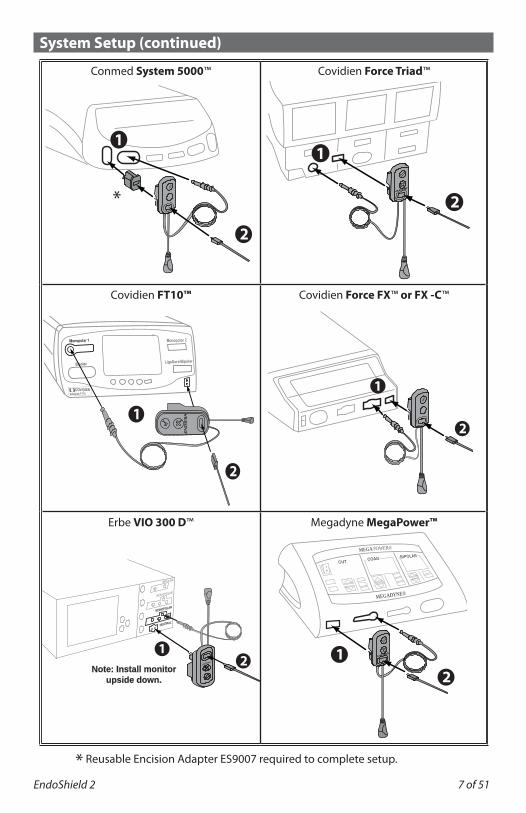
System Setup (continued)
Conmed System 5000™ Covidien Force Triad™
Covidien FT10™ Covidien Force FX™ or FX -C™
Erbe VIO 300 D™ Megadyne MegaPower™
* Reusable Encision Adapter ES9007 required to complete setup.
1
2
2
1
*
1
2
2
1
Monopolar 1
Bipolar LigaSure/Bipolar
Monopolar 2
[ ]COVIDIEN Valleylab FT10
12
Note: Install monitor upside down.
BIPOLAR
MONOPOLAR
MONOPOLAR
NEUTRAL
2
BIPOLAR COAG
CUT
MEGADYNE®
MEGA POWER®
1
10
8 of 51
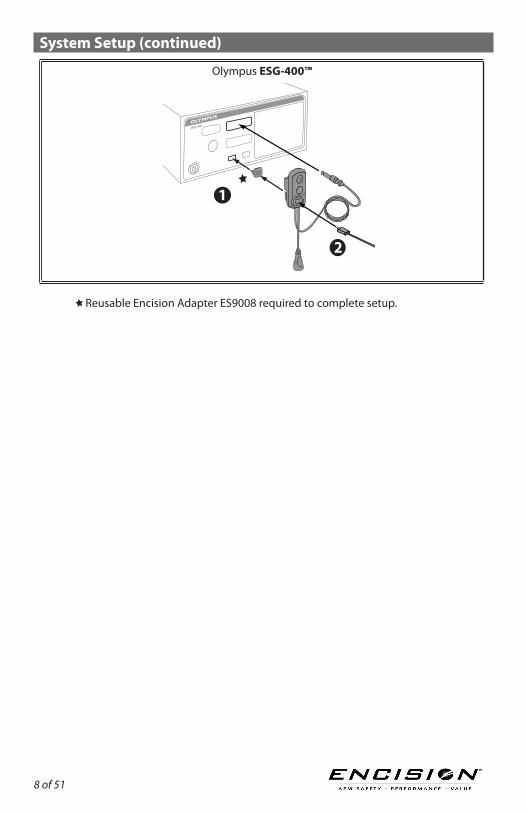
System Setup (continued)
Olympus ESG-400™
Reusable Encision Adapter ES9008 required to complete setup.
1
OLYMPUS
ESG-400
2
EndoShield 2 9 of 51
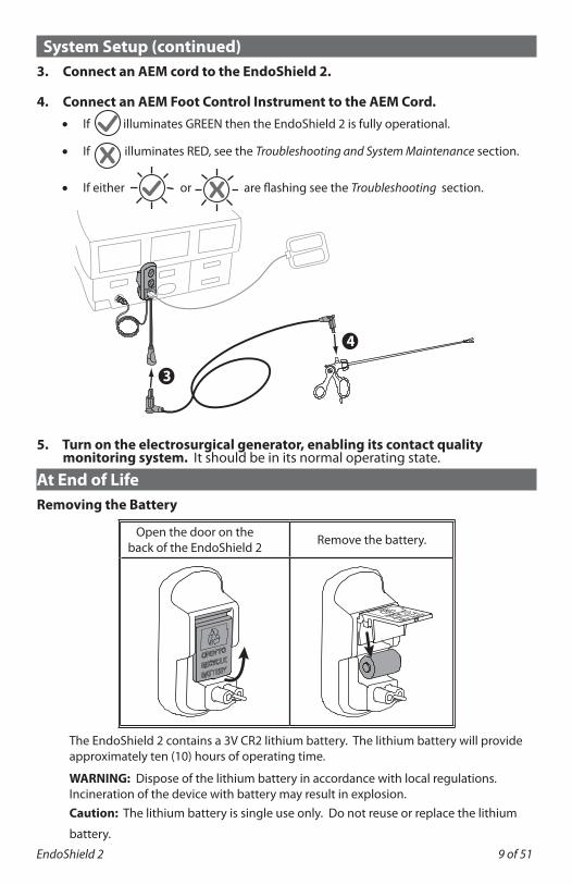
System Setup (continued)3. Connect an AEM cord to the EndoShield 2.
4. Connect an AEM Foot Control Instrument to the AEM Cord.• If illuminates GREEN then the EndoShield 2 is fully operational.
• If illuminates RED, see the Troubleshooting and System Maintenance section.
• If either or are flashing see the Troubleshooting section.
5. Turn on the electrosurgical generator, enabling its contact quality monitoring system. It should be in its normal operating state.
At End of LifeRemoving the Battery
Open the door on the back of the EndoShield 2 Remove the battery.
The EndoShield 2 contains a 3V CR2 lithium battery. The lithium battery will provide approximately ten (10) hours of operating time.
WARNING: Dispose of the lithium battery in accordance with local regulations. Incineration of the device with battery may result in explosion.Caution: The lithium battery is single use only. Do not reuse or replace the lithium
battery.
4
3

10 of 51
At End of Life (continued)End of Life Indicators
Discontinue use if any of the following are evident:• Intermittent electrical performance.• The device indicates a low or dead battery condition. See the Troubleshooting and
System Maintenance section for indications of low or dead battery.
ReprocessingWARNING: This product shall not be reprocessed.
Compatible ProductsFor successful operation, the EndoShield 2 must be used with the following compatible products.
Caution: Use of other accessories or cables may result in increased EMC emissions or decreased immunity.
Electrosurgical Generator
Electrosurgical Generator (ESU)Encision Adapter Required
Manufacturer Model
Conmed System 5000 ES9007
Covidien
Force Triad N/A
Force FX N/A
Force FX-C N/A
FT10 N/A
Erbe VIO 300 D N/A
Megadyne MegaPower N/A
Olympus ESG-400 ES9008
WARNING: The electrosurgical generators referenced here have been tested for use with the EndoShield 2. Use of an untested ESU may result in an inoperative active electrode monitoring system.Caution: All electrosurgical generators must have a contact quality monitoring circuit for return electrodes.
Return ElectrodeThe EndoShield 2 requires a dual-area patient return electrode.
Active ElectrodeThe foot-control instrument must have patented AEM technology and be manufactured by/for Encision Inc., or licensed by Encision Inc.Hand-control AEM instruments are not compatible with the EndoShield 2.
Instrument CordThe cord connecting the foot-controlled instrument to the EndoShield 2 must have patented AEM technology and be manufactured by/for Encision Inc., or licensed by Encision Inc.
EndoShield 2 11 of 51
Compatible Products (continued)Encision Adapter
Some electrosurgical generators require an adapter for setup of the EndoShield 2 (see the Electrosurgical Generator table above). Refer to the System Setup section for proper connections.

12 of 51
Troubleshooting and System MaintenanceMechanical InspectionBefore use, visually inspect the following items of EndoShield 2. Do not use if any of these items appear damaged:• Insulation of wiring and cables.• Instrument receptacles and connectors.
Correcting Setup Faults
Verify that the setup of the EndoShield 2 is complete.
Situation Recommended Action
No symbols illuminate on the front of AEM EndoShield 2.
Verify that a dual-area patient return electrode is connected properly and fully seated in the return electrode receptacle of the EndoShield 2.If the fault persists, replace the patient return electrode.
illuminates continuous RED
on the EndoShield 2.
Verify that the AEM Cord is properly connected to the EndoShield 2. Verify that the AEM instrument is properly connected to the AEM Cord.If the fault persists, replace the AEM instrument and/or AEM Cord.
No power to instrument,
but the illuminates GREEN on
the EndoShield 2.
Verify that both EndoShield 2 connectors to the electrosurgical generator (ESU) are properly and securely connected.Ensure that the power settings on the ESU are sufficient.Verify that the foot pedal is properly connected to the ESU.Reset the ESU's pad monitoring system (applies to some ESU models).Check the return electrode application to the patient. Follow the return electrode manufacturer’s instructions for proper placement.If the fault persists after performing all the previous steps, replace the AEM instrument or instrument cord.If the fault continues to persist, replace the EndoShield 2.
Low battery condition. illuminates flashing GREEN on the EndoShield 2.
The battery is nearing end of life. Finish existing procedure and replace the EndoShield 2.
Dead battery condition. illuminates flashing RED on the EndoShield 2.
Replace the EndoShield 2 immediately.
EndoShield 2 13 of 51
Troubleshooting and System Maintenance (continued)
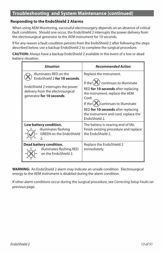
Responding to the EndoShield 2 AlarmsWhen using AEM Monitoring, successful electrosurgery depends on an absence of critical fault conditions. Should one occur, the EndoShield 2 interrupts the power delivery from the electrosurgical generator to the AEM instrument for 10 seconds.
If for any reason a fault condition persists from the EndoShield 2 after following the steps described below, use a backup EndoShield 2 to complete the surgical procedure.
CAUTION: Always have a backup EndoShield 2 available in the event of a low or dead battery situation.
Situation Recommended Action
illuminates RED on the EndoShield 2 for 10 seconds.
EndoShield 2 interrupts the power delivery from the electrosurgical generator for 10 seconds.
Replace the instrument.
If the continues to illuminate
RED for 10 seconds after replacing the instrument, replace the AEM Cord.
If the continues to illuminate
RED for 10 seconds after replacing the instrument and cord, replace the EndoShield 2.
Low battery condition.illuminates flashing GREEN on the EndoShield 2.
The battery is nearing end of life. Finish existing procedure and replace the EndoShield 2.
Dead battery condition. illuminates flashing RED on the EndoShield 2.
Replace the EndoShield 2 immediately.
WARNING: An EndoShield 2 alarm may indicate an unsafe condition. Electrosurgical energy to the AEM instrument is disabled during the alarm condition.
If other alarm conditions occur during the surgical procedure, see Correcting Setup Faults on previous page.
14 of 51
Troubleshooting and System Maintenance (continued)
Cleaning the EndoShield 2
WARNING: Electric Shock Hazard. Always unplug the EndoShield 2 before cleaning.
The EndoShield 2 may be cleaned in accordance with your facility's procedures.
1. Disconnect all accessories.2. Follow the procedures approved by your institution, or use a validated infection
control procedure.3. Dampen a cloth with a mild cleaning solution (100:1 water to mild detergent, by mass)
or disinfectant and thoroughly wipe all outside surfaces including cords.4. Ensure unit is dry before use.
Caution:
• Do not allow fluids to enter the EndoShield 2 housing.• Do not clean the EndoShield 2 with abrasive cleaning or disinfectant compounds,
solvents, or other materials that could damage the unit.• Do not steam sterilize the EndoShield 2.• Do not spray the EndoShield 2 directly with cleaning solution.
Storing the EndoShield 2
The EndoShield 2 should be stored within these parameters:• Temperature -13° to 140° F (-25° to 60° C).• Humidity: 5% to 95% relative, non-condensing.
If you store the EndoShield 2 at a temperature that is outside its normal operating range of 59° to 104° F (15° to 40° C), allow one hour for the EndoShield 2 to reach room temperature before use.
EndoShield 2 15 of 51
Warnings and Cautions Prior to using the EndoShield 2, read and review these instructions, the
instructions for use for the electrosurgical generator, and the instructions for use for all instruments and accessories to be used.
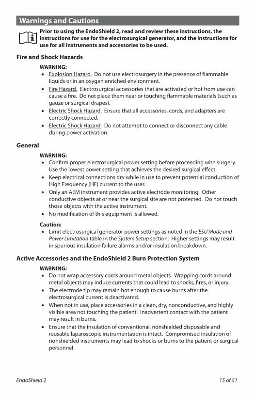
Fire and Shock HazardsWARNING:• Explosion Hazard. Do not use electrosurgery in the presence of flammable
liquids or in an oxygen enriched environment.• Fire Hazard. Electrosurgical accessories that are activated or hot from use can
cause a fire. Do not place them near or touching flammable materials (such as gauze or surgical drapes).
• Electric Shock Hazard. Ensure that all accessories, cords, and adapters are correctly connected.
• Electric Shock Hazard. Do not attempt to connect or disconnect any cable during power activation.
GeneralWARNING:• Confirm proper electrosurgical power setting before proceeding with surgery.
Use the lowest power setting that achieves the desired surgical effect.• Keep electrical connections dry while in use to prevent potential conduction of
High Frequency (HF) current to the user.• Only an AEM instrument provides active electrode monitoring. Other
conductive objects at or near the surgical site are not protected. Do not touch those objects with the active instrument.
• No modification of this equipment is allowed.
Caution:• Limit electrosurgical generator power settings as noted in the ESU Mode and
Power Limitation table in the System Setup section. Higher settings may result in spurious insulation failure alarms and/or insulation breakdown.
Active Accessories and the EndoShield 2 Burn Protection SystemWARNING:• Do not wrap accessory cords around metal objects. Wrapping cords around
metal objects may induce currents that could lead to shocks, fires, or injury.• The electrode tip may remain hot enough to cause burns after the
electrosurgical current is deactivated.• When not in use, place accessories in a clean, dry, nonconductive, and highly
visible area not touching the patient. Inadvertent contact with the patient may result in burns.
• Ensure that the insulation of conventional, nonshielded disposable and reusable laparoscopic instrumentation is intact. Compromised insulation of nonshielded instruments may lead to shocks or burns to the patient or surgical personnel.
16 of 51
Warnings and Cautions (continued)
• When using laparoscopic instrumentation with metal cannulas, the potential exists for abdominal wall burns to occur in the event of direct electrode tip contact to the cannula.
• Inspect cords for breaks, cracks, and/or nicks. If any are present, do not use. Failure to observe this precaution may result in injury or electrical shock to the patient or operating personnel.
• Damaged external insulation on instruments AND incorrect setup of the EndoShield 2 may result in a risk of unintended patient burn. Do not use product having damaged insulation.
• When an alarm is presented by the EndoShield 2, discontinue use of electrosurgery immediately. Find the cause of the alarm and correct it before continuing use.
• Damaged internal insulation of the instrument, or loss of shield continuity, may activate the EndoShield 2 alarms. For maximum patient safety, discontinue use of the instrument if this occurs.
• A single AEM instrument must be the sole conductor of energy to tissue. Do not conduct energy by touching an AEM instrument to a second instrument contacting tissue. The second device will not be protected from capacitive coupling and insulation failure.
Caution:• Read the instructions, warnings, and cautions provided with the EndoShield
2 accessories before using. Their specific instructions are not included in this manual.
• AEM Monitoring will not function without the use of a dual-area patient return electrode and an electrosurgical generator equipped with contact quality monitoring patient safety technology.
• No attempt should be made to reprocess this device.
Electromagnetic Compatibility (EMC) HazardsFor EMC specification tables, refer to the Technical Specifications section.
Caution:• Use of accessories, transducers, and cables other than those specified, with
the exception of transducers and cables sold by the manufacturer of the Equipment or System as replacement parts for internal components, may result in increased Emissions, or decreased Immunity of the Equipment or System.
EndoShield 2 17 of 51
Technical Specifications
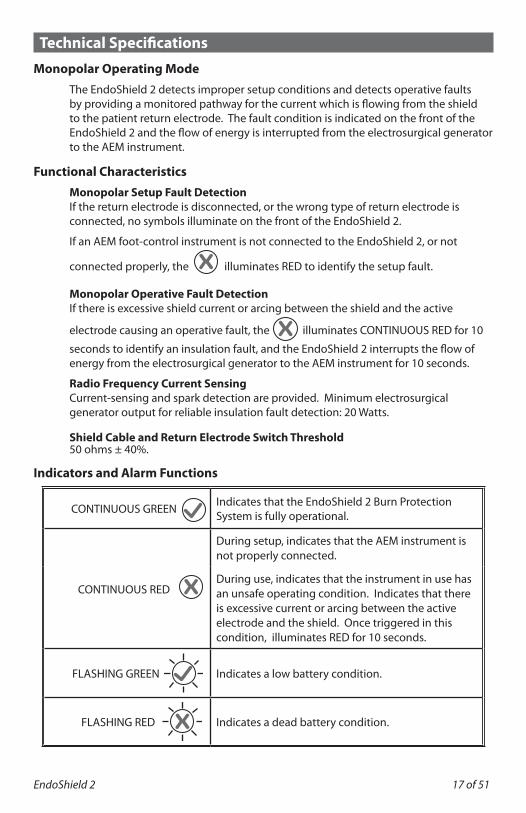
Monopolar Operating ModeThe EndoShield 2 detects improper setup conditions and detects operative faults by providing a monitored pathway for the current which is flowing from the shield to the patient return electrode. The fault condition is indicated on the front of the EndoShield 2 and the flow of energy is interrupted from the electrosurgical generator to the AEM instrument.
Functional CharacteristicsMonopolar Setup Fault DetectionIf the return electrode is disconnected, or the wrong type of return electrode is connected, no symbols illuminate on the front of the EndoShield 2.
If an AEM foot-control instrument is not connected to the EndoShield 2, or not
connected properly, the illuminates RED to identify the setup fault.
Monopolar Operative Fault Detection If there is excessive shield current or arcing between the shield and the active
electrode causing an operative fault, the illuminates CONTINUOUS RED for 10
seconds to identify an insulation fault, and the EndoShield 2 interrupts the flow of energy from the electrosurgical generator to the AEM instrument for 10 seconds.
Radio Frequency Current Sensing Current-sensing and spark detection are provided. Minimum electrosurgical generator output for reliable insulation fault detection: 20 Watts.
Shield Cable and Return Electrode Switch Threshold 50 ohms ± 40%.
Indicators and Alarm Functions
CONTINUOUS GREEN Indicates that the EndoShield 2 Burn Protection System is fully operational.
CONTINUOUS RED
During setup, indicates that the AEM instrument is not properly connected.
During use, indicates that the instrument in use has an unsafe operating condition. Indicates that there is excessive current or arcing between the active electrode and the shield. Once triggered in this condition, illuminates RED for 10 seconds.
FLASHING GREEN Indicates a low battery condition.
FLASHING RED Indicates a dead battery condition.

18 of 51
Technical Specifications (continued)
Connectors and CablesReturn Electrode Receptacle: A dual pin receptacle on the front of the EndoShield 2. The Return Electrode Receptacle connects a dual-area patient return electrode to the EndoShield 2.
Return Electrode Plug:A single pin plug on the rear of the EndoShield 2. The Return Electrode Plug connects to the electrosurgical generator's patient return electrode receptacle.
AEM Cord Connector:The AEM Cord Connector connects the EndoShield 2 to an AEM instrument cord.
Foot-Control Plug:A single active pin that connects the EndoShield 2 to the electrosurgical generator’s footswitch accessory receptacle.
Maximum Electrosurgical Generator Voltage4.1 kV peak.
Electrical CharacteristicsPower SourceLithium Battery, 3V CR2.
Patient Leakage CurrentSource or sink leakage current is 10 µA maximum.
Dimensions and WeightExternal Dimensions 4” tall x 2” wide x 2.5” deep, excluding integrated cords. AEM Instrument Connector: 7 inch cord length. Foot-Control Plug: 6 inch cord length.
Weight140 g (5 oz).
Environmental CharacteristicsOperating Temperature 59° to 104° F (15° to 40° C).
Storage and Transport Temperature -13° to 140° F (-25° to 60° C).
Operating, Storage and Transport Humidity 5% to 95% relative, non-condensing.
Atmospheric Pressure (Operating) 70 - 110 kPa.
EndoShield 2 19 of 51
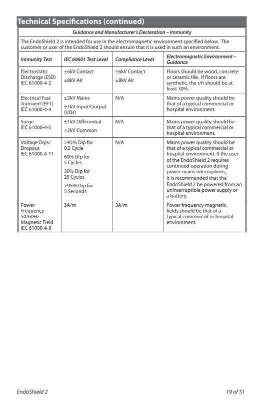
Technical Specifications (continued)Guidance and Manufacturer’s Declaration – Immunity
The EndoShield 2 is intended for use in the electromagnetic environment specified below. The customer or user of the EndoShield 2 should ensure that it is used in such an environment.
Immunity Test IEC 60601 Test Level Compliance Level Electromagnetic Environment – Guidance
Electrostatic Discharge (ESD)IEC 61000-4-2
±6kV Contact
±8kV Air
±6kV Contact
±8kV Air
Floors should be wood, concrete or ceramic tile. If floors are synthetic, the r/h should be at least 30%.
Electrical Fast Transient (EFT)IEC 61000-4-4
±2kV Mains
±1kV Input/Output (I/Os)
N/A Mains power quality should be that of a typical commercial or hospital environment.
SurgeIEC 61000-4-5
±1kV Differential
±2kV Common
N/A Mains power quality should be that of a typical commercial or hospital environment.
Voltage Dips/DropoutIEC 61000-4-11
>95% Dip for 0.5 Cycle
60% Dip for 5 Cycles
30% Dip for 25 Cycles
>95% Dip for 5 Seconds
N/A Mains power quality should be that of a typical commercial or hospital environment. If the user of the EndoShield 2 requires continued operation during power mains interruptions, it is recommended that the EndoShield 2 be powered from an uninterruptible power supply or a battery.
Power Frequency 50/60Hz Magnetic FieldIEC 61000-4-8
3A/m 3A/m Power frequency magnetic fields should be that of a typical commercial or hospital environment.
20 of 51
Technical Specifications (continued)
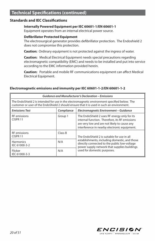
Standards and IEC ClassificationsInternally Powered Equipment per IEC 60601-1/EN 60601-1 Equipment operates from an internal electrical power source.
Defibrillator Protected Equipment The electrosurgical generator provides defibrillator protection. The Endoshield 2 does not compromise this protection.
Caution: Ordinary equipment is not protected against the ingress of water.
Caution: Medical Electrical Equipment needs special precautions regarding electromagnetic compatibility (EMC) and needs to be installed and put into service according to the EMC information provided herein.
Caution: Portable and mobile RF communications equipment can affect Medical Electrical Equipment.
Electromagnetic emissions and immunity per IEC 60601-1-2/EN 60601-1-2
Guidance and Manufacturer’s Declaration – Emissions
The EndoShield 2 is intended for use in the electromagnetic environment specified below. The customer or user of the EndoShield 2 should ensure that it is used in such an environment.
Emissions Test Compliance Electromagnetic Environment – Guidance
RF emissionsCISPR 11
Group 1 The EndoShield 2 uses RF energy only for its internal function. Therefore, its RF emissions are very low and are not likely to cause any interference in nearby electronic equipment.
RF emissionsCISPR 11
Class BThe EndoShield 2 is suitable for use in all establishments, including domestic, and those directly connected to the public low-voltage power supply network that supplies buildings used for domestic purposes.
HarmonicsIEC 61000-3-2
N/A
Flicker IEC 61000-3-3
N/A
EndoShield 2 21 of 51
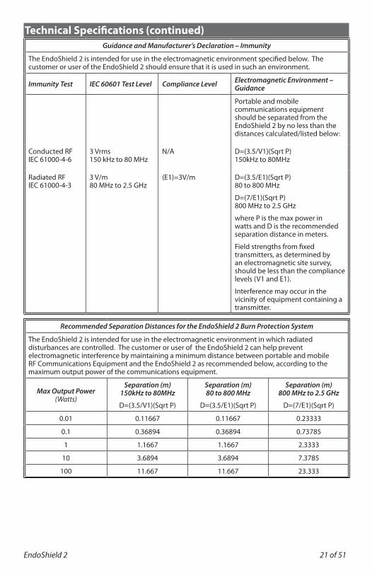
Technical Specifications (continued)Guidance and Manufacturer’s Declaration – Immunity
The EndoShield 2 is intended for use in the electromagnetic environment specified below. The customer or user of the EndoShield 2 should ensure that it is used in such an environment.
Immunity Test IEC 60601 Test Level Compliance Level Electromagnetic Environment – Guidance
Portable and mobile communications equipment should be separated from the EndoShield 2 by no less than the distances calculated/listed below:
Conducted RF IEC 61000-4-6
3 Vrms150 kHz to 80 MHz
N/A D=(3.5/V1)(Sqrt P) 150kHz to 80MHz
Radiated RF IEC 61000-4-3
3 V/m80 MHz to 2.5 GHz
(E1)=3V/m D=(3.5/E1)(Sqrt P) 80 to 800 MHz
D=(7/E1)(Sqrt P) 800 MHz to 2.5 GHz
where P is the max power in watts and D is the recommended separation distance in meters.
Field strengths from fixed transmitters, as determined by an electromagnetic site survey, should be less than the compliance levels (V1 and E1).
Interference may occur in the vicinity of equipment containing a transmitter.
Recommended Separation Distances for the EndoShield 2 Burn Protection System
The EndoShield 2 is intended for use in the electromagnetic environment in which radiated disturbances are controlled. The customer or user of the EndoShield 2 can help prevent electromagnetic interference by maintaining a minimum distance between portable and mobile RF Communications Equipment and the EndoShield 2 as recommended below, according to the maximum output power of the communications equipment.
Max Output Power(Watts)
Separation (m) 150kHz to 80MHz
D=(3.5/V1)(Sqrt P)
Separation (m) 80 to 800 MHz
D=(3.5/E1)(Sqrt P)
Separation (m) 800 MHz to 2.5 GHz
D=(7/E1)(Sqrt P)
0.01 0.11667 0.11667 0.23333
0.1 0.36894 0.36894 0.73785
1 1.1667 1.1667 2.3333
10 3.6894 3.6894 7.3785
100 11.667 11.667 23.333
22 of 51
Limited WarrantyExpress Warranty: ENCISION hereby warrants to Buyer that products purchased hereunder shall be free from defects in material and workmanship under normal use and service, as specified in ENCISION’s Instructions for Use provided with product, or until the labeled use by date.
Disclaimer: The express warranties set forth in this agreement are in lieu of, and buyer hereby expressly waives, all other guarantees and warranties of any kind, whether express, implied or statutory including, without limitation, merchantability, fitness for particular purpose, non-infringement or by sample, and all such other warranties are hereby disclaimed and excluded by ENCISION. The sole and exclusive remedy for breach of ENCISION’s warranty of the products shall be as stated herein.
Exclusions: The express warranty set forth above specifically excludes and does not apply to defects (i) caused through no fault of ENCISION during shipment to or from Buyer, (ii) caused by modifications or alterations made to the products by Buyer or any third party (iii) caused by unauthorized repair or maintenance performed on the products by Buyer or any third party, (iv) caused by the failure of Buyer to comply with any of the return procedures specified below, or (v) damaged by excessive current, temperature, physical stress or other deviation from the applicable environmental specifications.
Limitation of Remedies: ENCISION’s sole obligation and Buyer’s exclusive remedy for any breach of warranty is limited to the repair or replacement, at Encision’s option, of any warranted product that is returned to ENCISION in its standard shipping container or properly packed in accordance with ENCISION’s packing procedures, freight prepaid, where ENCISION’s examination shows the product to have failed under normal use. If ENCISION’s examination discloses that the returned product is not defective within the terms of this warranty, Buyer shall be subject to a $200.00 charge per individual product for testing expenses incurred by ENCISION and the product will be returned to Buyer, freight collect. Such repair or replacement and reshipment at ENCISION’s expense will be Buyer’s sole and exclusive remedy for such defect. ENCISION will pay shipping charges for the repaired or replaced from ENCISION’s factory to Buyer’s location. If, notwithstanding the foregoing, Buyer ships any product to ENCISION’s factory freight collect, then ENCISION shall ship the repaired or replaced product freight collect.
Warranty Procedures: Buyer shall request authorization from ENCISION prior to the return of each defective product for repair or replacement by ENCISION. Upon such request, ENCISION shall provide the address of the facility to which such product must be returned, together with Return Material Authorization (RMA) tracer number. ENCISION may, at its sole option, employ new or used parts for products to make such repair or replacement.
Stored Data: ENCISION shall not be liable for any loss or damage to any data stored in any product, including, without limitation, any data loss or damage resulting from any malfunction or defect or any loss or damage resulting from any inspection, repair, refurbishment, reconditioning or testing of the product or incurred in connection with transportation of the product to ENCISION or ENCISION’s authorized repair center.
EndoShield 2 23 of 51
Limited Warranty (continued)Technical Assistance: ENCISION’s warranty shall not be enlarged, and no obligation or liability shall arise out of ENCISION’s rendering of technical advice or assistance in connection with the products sold hereunder.
Limitation of Liability: To the extent allowable by applicable law, in no event shall ENCISION be liable for any special, incidental or consequential damages in connection with or arising out of the sale, installation, use, operation, service or repair of any product, whether based on breach of warranty or contract, strict liability, negligence or otherwise, whether or not ENCISION shall have been advised as to the possibility or reason for any such potential loss or damage. Direct damages shall be strictly limited to the cost to Buyer of the products sold or provided to Buyer, not withstanding any failure of essential purpose of any limited remedy.
Any evidence of repair, modification, or resterilization of this product will void this warranty.
24 of 51
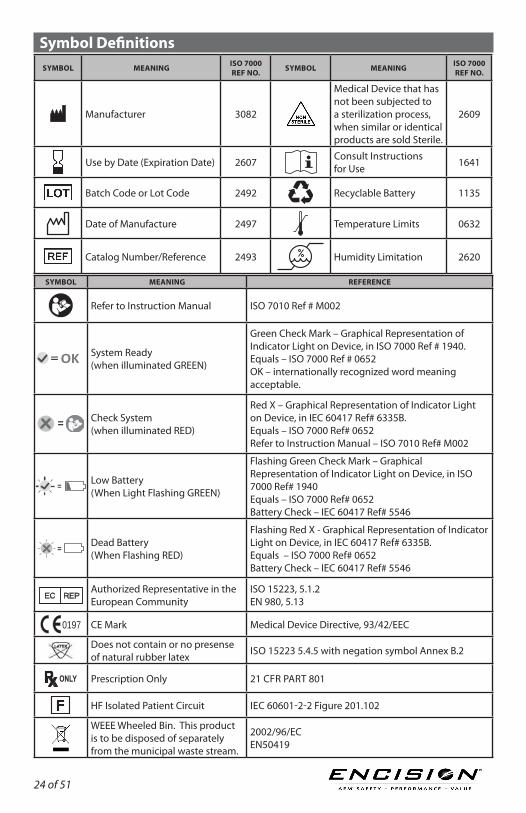
Symbol DefinitionsSYMBOL MEANING ISO 7000
REF NO. SYMBOL MEANING ISO 7000 REF NO.
Manufacturer 3082
Medical Device that has not been subjected to a sterilization process, when similar or identical products are sold Sterile.
2609
Use by Date (Expiration Date) 2607 Consult Instructions for Use 1641
Batch Code or Lot Code 2492 Recyclable Battery 1135
Date of Manufacture 2497 Temperature Limits 0632
Catalog Number/Reference 2493 Humidity Limitation 2620
SYMBOL MEANING REFERENCE
Refer to Instruction Manual ISO 7010 Ref # M002
OK= System Ready (when illuminated GREEN)
Green Check Mark – Graphical Representation of Indicator Light on Device, in ISO 7000 Ref # 1940. Equals – ISO 7000 Ref # 0652 OK – internationally recognized word meaning acceptable.
= Check System (when illuminated RED)
Red X – Graphical Representation of Indicator Light on Device, in IEC 60417 Ref# 6335B. Equals – ISO 7000 Ref# 0652 Refer to Instruction Manual – ISO 7010 Ref# M002
= Low Battery (When Light Flashing GREEN)
Flashing Green Check Mark – Graphical Representation of Indicator Light on Device, in ISO 7000 Ref# 1940 Equals – ISO 7000 Ref# 0652 Battery Check – IEC 60417 Ref# 5546
=Dead Battery (When Flashing RED)
Flashing Red X - Graphical Representation of Indicator Light on Device, in IEC 60417 Ref# 6335B. Equals – ISO 7000 Ref# 0652 Battery Check – IEC 60417 Ref# 5546
Authorized Representative in the European Community
ISO 15223, 5.1.2 EN 980, 5.13
0197 CE Mark Medical Device Directive, 93/42/EEC
Does not contain or no presense of natural rubber latex ISO 15223 5.4.5 with negation symbol Annex B.2
Prescription Only 21 CFR PART 801
HF Isolated Patient Circuit IEC 60601-2-2 Figure 201.102
WEEE Wheeled Bin. This product is to be disposed of separately from the municipal waste stream.
2002/96/EC EN50419
EndoShield 2 25 van 51
Return of Used Product If for any reason this product must be returned to ENCISION, a returned goods authorization is required prior to shipping. Appropriate return instructions may be obtained from ENCISION.
Product Changes ENCISION reserves the right to amend, modify, or to change any product, to introduce new products, to withdraw products and otherwise vary product specifications at any time without notice.
US Patents:# 5,312,401; 5,688,269; 8,007,494; 8,460,284; 8,500,728; D737,981.ENCISION®, AEM®, and AEM EndoShield® 2 are registered trademarks of ENCISION Inc. All other referenced trademarks are owned by their respective owners.
Manufactured by: © Copyright 2016 ENCISION Inc. ENCISION Inc All rights reserved6797 Winchester Circle 05704-004 Rev. E 2016/10Boulder, CO 80301 USA Printed in USAPhone: 303.444.2600 Fax: 303.444.2693
Authorized Representative(according to MDD93/42/EEC)MDSS GmbHSchiffgraben 4130175 Hannover, Germany
0197