instruction manual dräger msi em200-s · instruction manual dräger msi em200-s d 950 1 of 33...
TRANSCRIPT

Instruction Manual Dräger MSI EM200-s
Dräger MSI GmbH Rohrstraße 32 58093 Hagen Tel.: +49-2331 / 9584 - 0 Fax: +49-2331 / 9584 - 29 e-mail: [email protected] D 950; Edition 2011-01-01

Instruction Manual Dräger MSI EM200-s
D 950 1 of 33 Edition 2011-01-01
Content 1. Reference notes Page 3 1.1 Approvals 1.2 Information for use 1.3 Service 1.4 Specifications for disposal according WEEE 2. The instrument Page 4 3. Starting and function keys Page 5
3.1 Preparing for use 3.2 Function keys 3.3 Check of measuring gas duct (tightness test) Page 6 3.4 Terminating measurement
4. Selection of functions Page 7 5. Flue gas measurements
5.1 Select type of flue gas measurement 5.2 Flue gas analysis Page 8 5.3 Average measurements Page 11 5.4 Combustion air measurement in air ducts Page 12 5.6 Fresh air adjust Page 14
6. Pressure measurements 7. Special functions Page 16
7.1 Ambient air CO measurement 7.2 Measuring combustion air temperature Page 17 7.3 Automatic switch off 7.4 Shelter of the CO sensor 7.5 Online data transfer Page 18
8. Documentation menu

Instruction Manual Dräger MSI EM200-s
Edition 2011-01-01 2 of 33 D 950
Content (Page 3) 9. Data processing Page 18
9.1 Store data 9.2 Data menu Page 19 9.3 Info function of data menu 9.4 Show stored data records Page 20
9.5 Clear data files 9.6 Selection of table type
10. Info function Page 21 11. Selection or input of customer ID Page 22 12. Settings Page 23
12.1 General settings 12.2 Selection of damping Page 24 12.3 Date and time adjust 12.4 Backlight adjust Page 25 12.5 Key beep switch on / off 12.6 Printer protocol selection 12.7 Display contrast adjust Page 26
12.8 Factory setting restore 12.9 Display language selection Page 27 12.10 Efficiency and stack loss
13. Warning hints, error messages and operation references Page 28 13.1 Warning hints
13.2 Error messages 13.3 Operation references Page 30 14. Technical data Page 31 15. Maintenance and service Page 33

Instruction Manual Dräger MSI EM200-s
D 950 3 of 33 Edition 2011-01-01
1. Reference notes 1.1 Approvals The flue gas analyser MSI EM200-s is approved according the European Standard EN 50379 part 1 and part 3. 1.2 Information for use The MSI EM 200-s is an electronic multiple channel measuring instrument for analysing the flue gas of combustions and industrial processes. The MSI EM200-s is unlicensed as a gas detection alarm or personal security equipment. Any use of the MSI EM200-s requires a full understanding and strict adherence to these instructions and to national and international standards. The instrument has only to be used for the purposes specified in here. The display screens used in this instruction manual are only examples! Only locked values can be printed and stored. 1.3 Service To maintain accuracy and correct function the MSI EM200-s should be checked and re-calibrated by authorized service people once a year. 1.4 Specifications for disposal according WEEE As from 2005 EC specifications for disposal of electric and electronic equipment are valid. These are regulated in the 2002/96/EC directive and respective national law. Essential content is the establishment of special collection and recycling facilities for pri-vate users. Since this device is not registered for private users, it is not allowed to dispose it in this way. For disposal you can send it back to your local Dräger Safety organisation and if re-quested, get further information concerning this matter from Dräger MSI GmbH.
Instruction Manual Dräger MSI EM200-s
Edition 2011-01-01 4 of 33 D 950
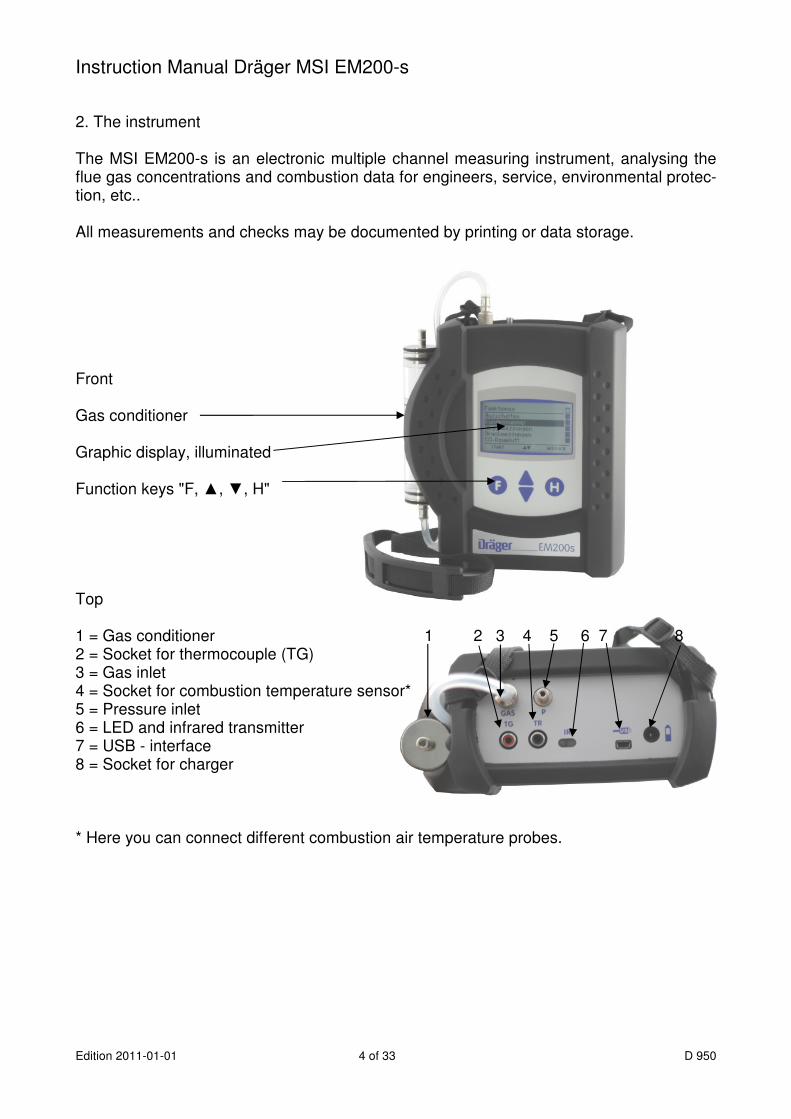
2. The instrument The MSI EM200-s is an electronic multiple channel measuring instrument, analysing the flue gas concentrations and combustion data for engineers, service, environmental protec-tion, etc.. All measurements and checks may be documented by printing or data storage. Front Gas conditioner Graphic display, illuminated Function keys "F, ▲, ▼, H" Top 1 = Gas conditioner 1 2 3 4 5 6 7 8 2 = Socket for thermocouple (TG) 3 = Gas inlet 4 = Socket for combustion temperature sensor* 5 = Pressure inlet 6 = LED and infrared transmitter 7 = USB - interface 8 = Socket for charger * Here you can connect different combustion air temperature probes.

Instruction Manual Dräger MSI EM200-s
D 950 5 of 33 Edition 2011-01-01
3. Starting and operating keys 3.1 Preparing the instrument Make sure that all components are in good condition e.g.: − no condensate in the gas conditioner − the filter fleece and the filter disks are clean − the gas hoses are in good condition − the probe is free from defects Connect the gas conditioner with the gas inlet of the MSI EM200-s. Never forget to use the gas conditioner. Verify that fresh air will be sucked through the gas conditioner before switching on, be-cause the zero signals of the sensors are checked with fresh air. 3.2 Function keys 3.2.1 Switching on / off of the MSI EM200-s Switch on the instrument by pushing for a second the buttons “F” and “H” together. If the annual service has do be done, a month earlier the MSI EM200-s displays a reminder. After pushing “F” (CONTINUE), or direct after switching on the display will read: Battery symbol Pump is working The time and the software version is shown and the battery symbols show the batteries capacity. The bar represents the progress of the run in of the el.-chem. sensors and the progress of the check function. The system check lasts 30 seconds. If errors have been detected, warning hints or error messages (see 13.) will be generated. Otherwise the menu “selection of functions” (see 4.) will be called. Switch off the instrument by using the switch off function in the menu “selection of func-tions” (see 4.) or by pushing “F” until the display reads “Switch off” (ca. > 3 sec).
Instruction Manual Dräger MSI EM200-s
Edition 2011-01-01 6 of 33 D 950
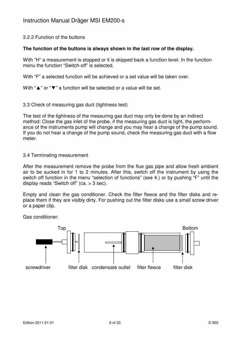
3.2.2 Function of the buttons The function of the buttons is always shown in the last row of the display. With “H” a measurement is stopped or it is skipped back a function level. In the function menu the function “Switch-off” is selected. With “F” a selected function will be achieved or a set value will be taken over. With “▲” or “▼” a function will be selected or a value will be set. 3.3 Check of measuring gas duct (tightness test) The test of the tightness of the measuring gas duct may only be done by an indirect method: Close the gas inlet of the probe, if the measuring gas duct is tight, the perform-ance of the instruments pump will change and you may hear a change of the pump sound. If you do not hear a change of the pump sound, check the measuring gas duct with a flow meter. 3.4 Terminating measurement After the measurement remove the probe from the flue gas pipe and allow fresh ambient air to be sucked in for 1 to 2 minutes. After this, switch off the instrument by using the switch off function in the menu “selection of functions” (see 4.) or by pushing “F” until the display reads “Switch off” (ca. > 3 sec). Empty and clean the gas conditioner. Check the filter fleece and the filter disks and re-place them if they are visibly dirty. For pushing out the filter disks use a small screw driver or a paper clip. Gas conditioner: Top Bottom screwdriver filter disk condensate outlet filter fleece filter disk

Instruction Manual Dräger MSI EM200-s
D 950 7 of 33 Edition 2011-01-01
4. Selection of functions Selectable functions are: Switch-off = Switches off the instrument Customer ID = Calls function “selection or input of customer ID” (see 11.) Flue gas analysis = Calls menu “select type of flue gas measurement” (see 5.1) Pressure tests = Calls menu “pressure measurements” (see 6.) CO ambient = Calls menu “ambient air CO measurement” (see. 7.1) Memory = Calls “data menu” (see 9.2) Info = Calls “info function” (see 10.) Settings = Calls menu “settings” (see 12.) 5. Flue gas measurements 5.1 Select type of flue gas measurement Selectable flue gas measurements are: Analysis / stack losses = Starts flue gas analysis (see 5.2) Average = Starts measurement of average values (see 5.3) Comb.air O2 = starts O2 measurement of combustion air in ducts (see 5.4) Fresh air adjust = zero point calibration with fresh ambient air (see 5.5) 5.1.1 Preparing for flue gas analyses and measurement of average values Connect the hose of the probe with the gas conditioner and then the plug of the thermo-couple (marked red) with the socket marked “TG”. The combustion temperature sensor is plugged into the socket “TR”. After starting the burner wait until the combustion is steady going. Direct after start the burner may emit high concentrations of toxic gases and soot and this would needlessly pollute the instruments sensors. After start of the measurement the fuel type selection (see 5.1.2) is called.
Instruction Manual Dräger MSI EM200-s
Edition 2011-01-01 8 of 33 D 950
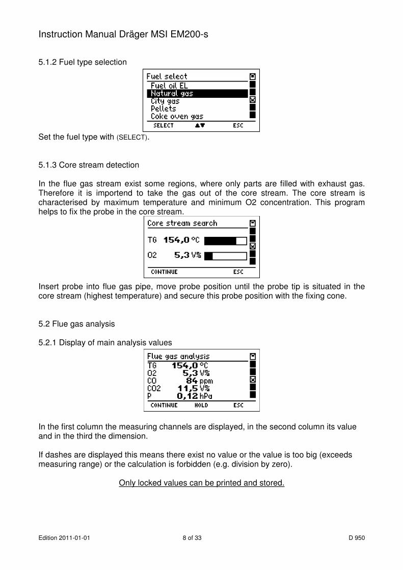
5.1.2 Fuel type selection Set the fuel type with (SELECT). 5.1.3 Core stream detection In the flue gas stream exist some regions, where only parts are filled with exhaust gas. Therefore it is importend to take the gas out of the core stream. The core stream is characterised by maximum temperature and minimum O2 concentration. This program helps to fix the probe in the core stream. Insert probe into flue gas pipe, move probe position until the probe tip is situated in the core stream (highest temperature) and secure this probe position with the fixing cone. 5.2 Flue gas analysis 5.2.1 Display of main analysis values In the first column the measuring channels are displayed, in the second column its value and in the third the dimension. If dashes are displayed this means there exist no value or the value is too big (exceeds measuring range) or the calculation is forbidden (e.g. division by zero).
Only locked values can be printed and stored.
Instruction Manual Dräger MSI EM200-s
D 950 9 of 33 Edition 2011-01-01
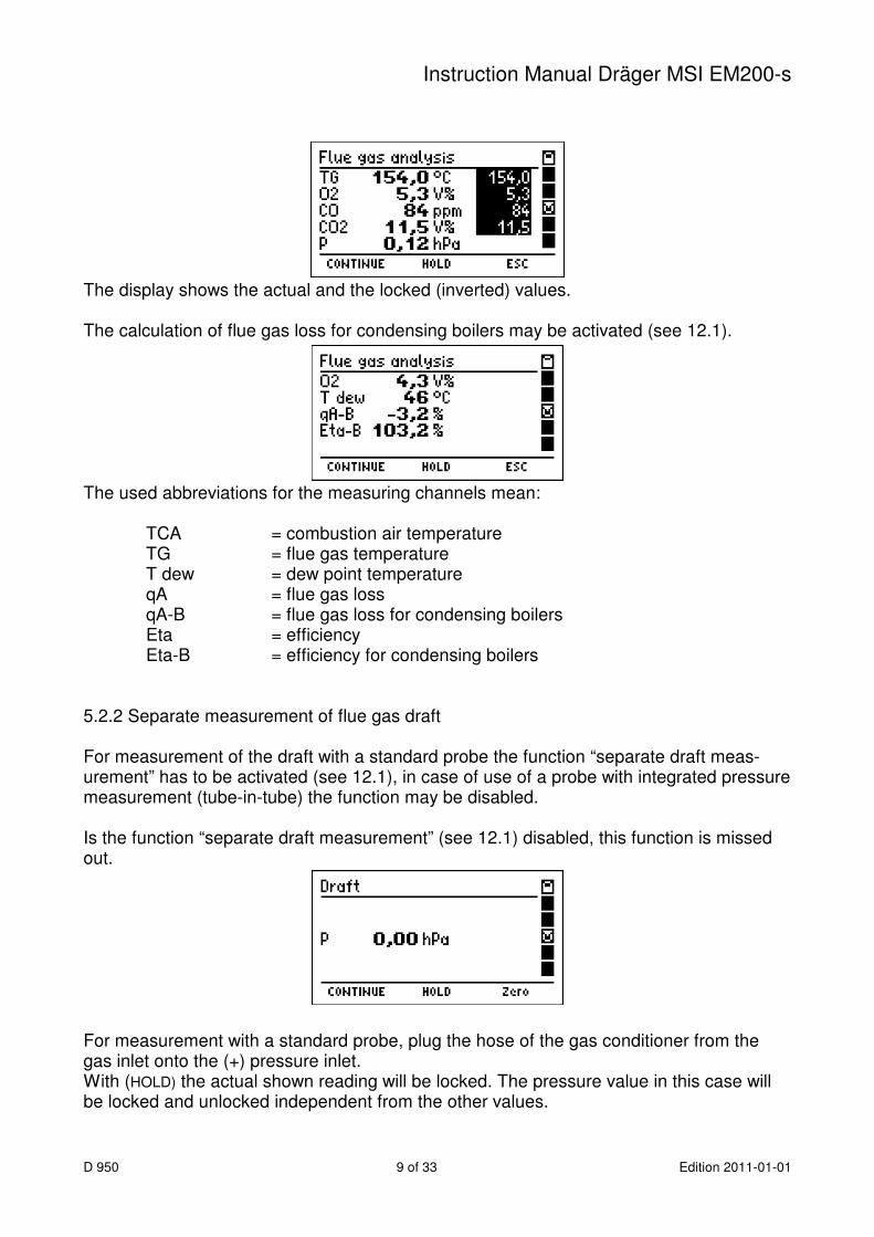
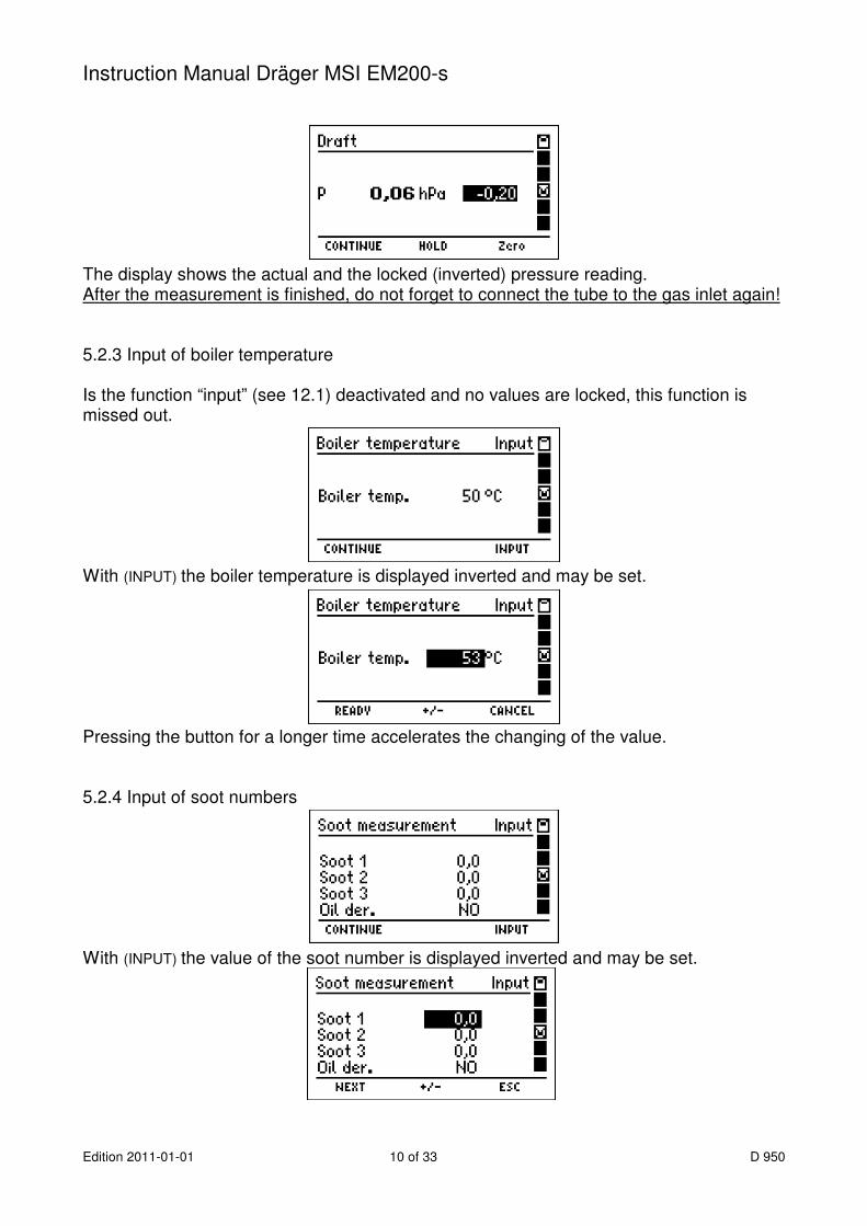
The display shows the actual and the locked (inverted) values. The calculation of flue gas loss for condensing boilers may be activated (see 12.1). The used abbreviations for the measuring channels mean:
TCA = combustion air temperature TG = flue gas temperature T dew = dew point temperature qA = flue gas loss qA-B = flue gas loss for condensing boilers Eta = efficiency Eta-B = efficiency for condensing boilers
5.2.2 Separate measurement of flue gas draft For measurement of the draft with a standard probe the function “separate draft meas-urement” has to be activated (see 12.1), in case of use of a probe with integrated pressure measurement (tube-in-tube) the function may be disabled. Is the function “separate draft measurement” (see 12.1) disabled, this function is missed out. For measurement with a standard probe, plug the hose of the gas conditioner from the gas inlet onto the (+) pressure inlet. With (HOLD) the actual shown reading will be locked. The pressure value in this case will be locked and unlocked independent from the other values.
Instruction Manual Dräger MSI EM200-s
Edition 2011-01-01 10 of 33 D 950
The display shows the actual and the locked (inverted) pressure reading. After the measurement is finished, do not forget to connect the tube to the gas inlet again! 5.2.3 Input of boiler temperature Is the function “input” (see 12.1) deactivated and no values are locked, this function is missed out. With (INPUT) the boiler temperature is displayed inverted and may be set. Pressing the button for a longer time accelerates the changing of the value. 5.2.4 Input of soot numbers With (INPUT) the value of the soot number is displayed inverted and may be set.
Instruction Manual Dräger MSI EM200-s
D 950 11 of 33 Edition 2011-01-01
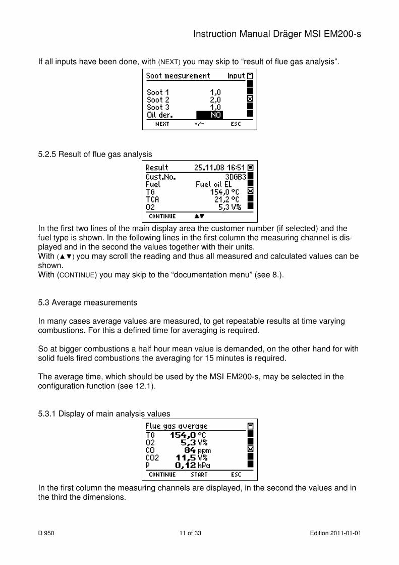
If all inputs have been done, with (NEXT) you may skip to “result of flue gas analysis”. 5.2.5 Result of flue gas analysis In the first two lines of the main display area the customer number (if selected) and the fuel type is shown. In the following lines in the first column the measuring channel is dis-played and in the second the values together with their units. With (▲▼) you may scroll the reading and thus all measured and calculated values can be shown. With (CONTINUE) you may skip to the “documentation menu” (see 8.). 5.3 Average measurements In many cases average values are measured, to get repeatable results at time varying combustions. For this a defined time for averaging is required. So at bigger combustions a half hour mean value is demanded, on the other hand for with solid fuels fired combustions the averaging for 15 minutes is required. The average time, which should be used by the MSI EM200-s, may be selected in the configuration function (see 12.1). 5.3.1 Display of main analysis values In the first column the measuring channels are displayed, in the second the values and in the third the dimensions.

Instruction Manual Dräger MSI EM200-s
Edition 2011-01-01 12 of 33 D 950
After (START) the chosen time (see 12.1) runs. After the average period the current and the mean measurement values (inverse) are dis-played. As described in the chapters 5.2.2 to 5.2.4 the separate measurement of flue gas draft, the input of boiler temperature and the input of soot numbers may be called. After the average measurement is finished "result of average measurement" (see.5.3.2) is called. 5.3.2 Result of average measurement With (CONTINUE) the “documentation menu” (see 8.) is called. 5.4 Combustion air measurement in air ducts At room-air independent combustions, you may check the tightness of the combined com-bustion-air duct and flue exhaust system, by measuring the O2-concentration in the air duct with a special multi hole probe. Connect the hose of the probe with the gas conditioner.

Instruction Manual Dräger MSI EM200-s
D 950 13 of 33 Edition 2011-01-01
In fresh air the value of the O2 concentration is 21 Vol. %. Is the flue exhaust pipe not tight, the O2 concentration will decrease. Displayed are the value of O2 (O2-CA), the O2 difference to 21,0 Vol. % (O2-Dif) and the value of CO (CO-CA). Displayed are the actual and the locked values. With (CONTINUE) the pressure measurement in the combustion air duct is called. For measurement with a standard probe, plug the hose of the gas conditioner from the gas inlet onto the (+) pressure inlet. With (HOLD) the actual shown reading will be locked. With (CONTINUE) the result of the combustion air measurement is called. With (CONTINUE) “documentation menu” is called (see 8.).

Instruction Manual Dräger MSI EM200-s
Edition 2011-01-01 14 of 33 D 950
5.5 Fresh air adjust This function allows a zero point calibration of all el.-chem. sensors and of the pressure sensor, before starting a flue gas analysis. The MSI EM200-s asks to care that fresh air may be sucked through the gas conditioner. There should no tube be connected to the pressure inlet. With (CONTINUE) the actual values of all el.-chem. sensors and of the pressure sensor are displayed. With (START) all zero points are recalibrated. 6. Pressure measurement For pressure measurement (gas or nozzle pressure) connect pressure inlet via pressure probe with the measuring point. On the left of the display screen the pressure value together with its dimension unit and on the right the selectable functions are displayed.

Instruction Manual Dräger MSI EM200-s
D 950 15 of 33 Edition 2011-01-01
Selectable functions are: Zero = The shown value is set to zero Damping = Calls adjusting the damping value (see 12.3) Start = Start of pressure measurement On the left of the display screen the first value is the pressure at the beginning of this measurement, the second value is the actual pressure value, the third is the mean value of the running measurement. The fourth value informs how long the pressure measure-ment is running. With (SELECT) the measurement may be finished. The first value is the actual pressure; the second value is the average of the last meas-urement. The start-, the stop- and 10 until 20 measurement values between them and the elapsed time have been stored in a buffer. These buffered values may be stored and transferred to a PC. With help of the software “EM Tools” a measurement report including a diagram of the time depending pressure measurement may be printed. Selectable functions are: Zero = The shown value is set to zero Damping = Calls function for adjusting the damping value (see 12.3) Start = Start of a new pressure measurement, the actual values are released. Print = Transfer of measurement data to an IR printer Store = Calls the function “storing of pressure measurements” (see 9.1)

Instruction Manual Dräger MSI EM200-s
Edition 2011-01-01 16 of 33 D 950
7. Special functions 7.1 Ambient air CO measurement In some countries (e.g. Spain) exists a regulation, to measure ambient air CO at the site of a combustion to prove their tightness. For this the MSI EM200-s needs no external sensor. At a place with fresh air without CO content, the reading has to be 0 ppm. Is the reading not 0 ppm, pull the hose off of the gas inlet of the gas conditioner and wait for a while and push (ZERO). The displayed value will become zero, this zero point is inde-pendent from the CO zero point of normal flue gas measurements. Slip the hose on the gas inlet again! With (CONTINUE) the actual value of CO in the air will be displayed. Go to the site of the combustion. The MSI EM200-s sucks ambient air in through the nor-mal probe and displays the CO concentration of the ambient air. With (HOLD) the actual value may be locked. With (CONTINUE) the result of the ambient air CO measurement is displayed: With (CONTINUE) the “documentation menu” may be called (see 8.).

Instruction Manual Dräger MSI EM200-s
D 950 17 of 33 Edition 2011-01-01
7.2 Measuring Combustion Air Temperature The MSI EM200-s is equipped with a built-in temperature sensor, which is able to meas-ure in first approximation the temperature of the ambient (room temperature) and where applicable the temperature of the combustion air. If no external sensor is plugged in, it is displayed after the check function. In order to enhance the accuracy of the measurement and according to the requirements of EN 50379 part 3, it is recommended to use an external temperature probe. The instru-ment recognises if an external probe is connected and takes automatically the results measured by the adapted probe. 7.3 Automatic switch off In order to increase the battery life time the instrument is provided with a standby mode. In case no key has been touched for 30 minutes and the instrument is not in a measuring mode (flue gas, pressure, CO-air measurement) the display back light and the gas pump will be switched off. If any key will be touched the MSI EM200-s automatically switches on again. The information "standby" is shown in the display. After 30 minutes of standby time the instrument will be switched off completely. 7.4 Shelter of the CO sensor The instrument is equipped with a special function protecting the sensors from getting harmed by too high CO concentrations. Already during the first contact with the flue gas the MSI EM200-s realises how fast the concentration rises and recognises if the measuring range (8,000 ppm) will be exceeded. The pump is switched off and the display demands to draw in fresh air. By pushing a button the pump starts again. Has the concentration been very high, it is possible that the concentration at the sensor is still > 8,000 ppm. In this case bars are dis-played as the CO value. Wait until the concentration is < 1,000 ppm before starting measuring again.
Instruction Manual Dräger MSI EM200-s
Edition 2011-01-01 18 of 33 D 950
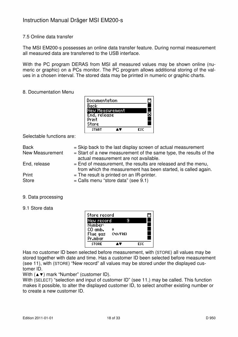
7.5 Online data transfer The MSI EM200-s possesses an online data transfer feature. During normal measurement all measured data are transferred to the USB interface. With the PC program DERAS from MSI all measured values may be shown online (nu-meric or graphic) on a PCs monitor. The PC program allows additional storing of the val-ues in a chosen interval. The stored data may be printed in numeric or graphic charts. 8. Documentation Menu Selectable functions are: Back = Skip back to the last display screen of actual measurement New Measurement = Start of a new measurement of the same type, the results of the
actual measurement are not available. End, release = End of measurement, the results are released and the menu,
from which the measurement has been started, is called again. Print = The result is printed on an IR-printer. Store = Calls menu “store data” (see 9.1) 9. Data processing 9.1 Store data Has no customer ID been selected before measurement, with (STORE) all values may be stored together with date and time. Has a customer ID been selected before measurement (see 11), with (STORE) “New record” all values may be stored under the displayed cus-tomer ID. With (▲▼) mark “Number” (customer ID). With (SELECT) “selection and input of customer ID” (see 11.) may be called. This function makes it possible, to alter the displayed customer ID, to select another existing number or to create a new customer ID.

Instruction Manual Dräger MSI EM200-s
D 950 19 of 33 Edition 2011-01-01
Is an existing data record selected, this data record may be overwritten. The records may be displayed with date or customer ID (see 9.6). 9. 2 Data menu Selectable functions are: Info = Calls info function of the data menu (see 9.3) Show, pos at last = Show last stored data record (see 9.4) Show, pos at first = Show first stored data record (see 9.4) Clear data file = Delete all stored data records (see 9.5) Table settings = Selection of table type (see 9.6) 9.3 Info function of data menu The display informs about the number of possible data records, the number of stored cus-tomer and measurement records and the date and time of the first and the last storing.

Instruction Manual Dräger MSI EM200-s
Edition 2011-01-01 20 of 33 D 950
9.4 Show stored data records If "Show, pos at first" or "Show, pos at last" has been called, the stored data records are displayed. In the first case the first data record is marked, in other case the last one. The head line informs about the number of the marked record and the number of stored records. The table informs about the type of measurement and the customer ID or date and time of storing (see 9.6). With (SHOW) the result screen of this measurement may be displayed. Following types of measurement may be shown: Comb.air O2 = Combustion air O2 concentration in air duct (see 5.4) CO Amb. = CO concentration in ambient air (see 7.1) Flue gas = Flue gas analysis and average (see 5.2.5 and 5.3.2) Press. mbar = Pressure measurements (see 6) 9.5 Clear Data Files With (YES) all stored data records will be deleted. 9.6 Selection of table type With this function the description of the table of data records (see 9.1 and 9.4) may be selected, either date and time or customer IDs. With (▲▼) may be changed between the description, date and time or customer IDs. With (END) the table type is accepted.

Instruction Manual Dräger MSI EM200-s
D 950 21 of 33 Edition 2011-01-01
Description with date and time: Description with customer numbers: 10. Info function The display informs about the analyser (MSI EM200-s), the manufacturer (Dräger MSI GmbH), the date and time when info function was called, the version of the firmware (e.g. 1.2,006) and the serial number of the analyser. With (CONTINUE) you get informed about all existing warnings and error messages (see 13.). With (CONTINUE) a complete system report may be printed. By means of this report, skilled service technician are able to find out easier, if malfunc-tions of the MSI EM200-s are existent.

Instruction Manual Dräger MSI EM200-s
Edition 2011-01-01 22 of 33 D 950
11. Selection or input of customer ID With the PC program “EM Tools” it is possible to compile a list with customer number and name and send all or parts of it to the MSI EM200-s. With this function you may create new customer numbers, or if numbers are stored in the MSI EM200-s you may select one of them or alter it. With (CONTINUE) the marked customer number and (if existing) object number and cus-tomer name are displayed. Has “Input” been called, the character which is marked by “▲” may be modified or a new customer ID may be created. Selectable characters are letters (A-Z), numbers (0 - 9) and 4 additional signs (_ . - /). The sign “_” means no character. With (►) the next position on the right is marked with “▲”. With (READY) the shown customer number is stored, selected and you skip back to the function, from where “selection or input of customer ID” has been called. The selected customer number is used for all measurements, until the instrument is swit-ched off or a new customer number is selected.

Instruction Manual Dräger MSI EM200-s
D 950 23 of 33 Edition 2011-01-01
12. Settings Selectable functions are: General = Call the menu for general settings (see 12.1) P-damping = Select the damping (see12.2) Clock = Adjust date and time (see 12.3) Backlight = Adjust backlight (see 12.4) Key beep = Switch on / off the key beep (see 12.5) Printer = Select HP or MSI printer protocol (see 12.6) Contrast = Adjust display contrast (see 12.7) Factory settings = Restore factory setting (see 12.8) Language = Select language of display text (see 12.9) 12.1 General settings With (INPUT) the marked setting may be changed. The changeable setting is displayed inverted. With pushing (+/-) or (ON/OFF) the setting may be modified. With (OK) the inverted displayed setting is activated. With (END) all general settings may be accepted.
Instruction Manual Dräger MSI EM200-s
Edition 2011-01-01 24 of 33 D 950
Selectable general settings are: setting choices function Input ON / OFF enables / disables:
input of vessel temperature (see 5.2 / 5.3) input of soot numbers (see 5.2 / 5.3)
Average time 30 s 30 seconds average time 60 s 1 minute average time 15 min average time needed for solid fuel combustions 30 min 1/2 hour average time Draft ON / OFF additional measurement of chimney draft
(see 5.2.2) Condens. boiler ON / OFF stack loss calculation for condensing boilers
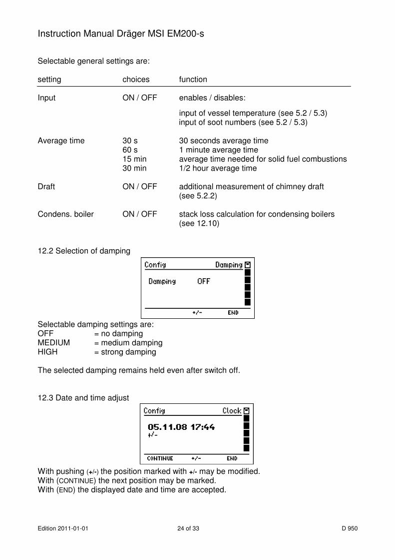
(see 12.10) 12.2 Selection of damping Selectable damping settings are: OFF = no damping MEDIUM = medium damping HIGH = strong damping The selected damping remains held even after switch off. 12.3 Date and time adjust With pushing (+/-) the position marked with +/- may be modified. With (CONTINUE) the next position may be marked. With (END) the displayed date and time are accepted.

Instruction Manual Dräger MSI EM200-s
D 950 25 of 33 Edition 2011-01-01
12.4 Backlight adjust Selectable intensity levels are: 0 %, 25 %, 50 %, 75 % and 100 %. The selected intensity level remains held even after switch off. 12.5 Key beep switch on / off With (ON / OFF) will be changed between “Key beep ON” and “Key beep OFF”. The selected function remains held even after switch off. 12.6 Printer Protocol Selection With (▲▼) the printer MSI IR3 or the printer HP may be selected. Printer MSI IR3: Data transfer and printing is much quicker than with HP compatible print-ers. Printer HP: Data transfer is conforming to the HP protocol and fits to all HP compatible printers, of course for MSI IR3 too. The selected function remains held, even after switch off.
Instruction Manual Dräger MSI EM200-s
Edition 2011-01-01 26 of 33 D 950
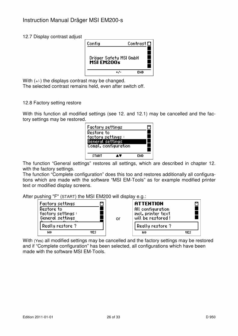
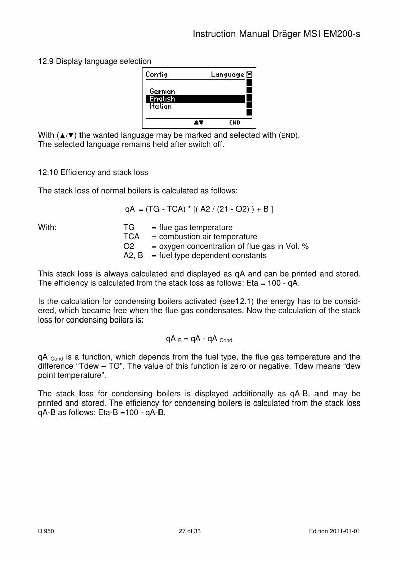
12.7 Display contrast adjust With (+/-) the displays contrast may be changed. The selected contrast remains held, even after switch off. 12.8 Factory setting restore With this function all modified settings (see 12. and 12.1) may be cancelled and the fac-tory settings may be restored. The function “General settings” restores all settings, which are described in chapter 12. with the factory settings. The function “Complete configuration” does this too and restores additionally all configura-tions which are made with the software “MSI EM-Tools” as for example modified printer text or modified display screens. After pushing "F" (START) the MSI EM200 will display e.g.: ^ or With (Yes) all modified settings may be cancelled and the factory settings may be restored and if “Complete configuration” has been selected, all configurations which have been made with the software MSI EM-Tools.
Instruction Manual Dräger MSI EM200-s
D 950 27 of 33 Edition 2011-01-01
12.9 Display language selection With (▲/▼) the wanted language may be marked and selected with (END). The selected language remains held after switch off. 12.10 Efficiency and stack loss The stack loss of normal boilers is calculated as follows:
qA = (TG - TCA) * [( A2 / (21 - O2) ) + B ] With: TG = flue gas temperature TCA = combustion air temperature O2 = oxygen concentration of flue gas in Vol. % A2, B = fuel type dependent constants This stack loss is always calculated and displayed as qA and can be printed and stored. The efficiency is calculated from the stack loss as follows: Eta = 100 - qA. Is the calculation for condensing boilers activated (see12.1) the energy has to be consid-ered, which became free when the flue gas condensates. Now the calculation of the stack loss for condensing boilers is:
qA B = qA - qA Cond qA Cond is a function, which depends from the fuel type, the flue gas temperature and the difference “Tdew – TG”. The value of this function is zero or negative. Tdew means “dew point temperature”. The stack loss for condensing boilers is displayed additionally as qA-B, and may be printed and stored. The efficiency for condensing boilers is calculated from the stack loss qA-B as follows: Eta-B =100 - qA-B.

Instruction Manual Dräger MSI EM200-s
Edition 2011-01-01 28 of 33 D 950
13. Warning hints, error messages and operation references Already after being switched on, as well as during the measurement process, the MSI EM200-s checks the function of all measuring channels. Warning hints and error mes-sages are shown before the selection of functions or during normal function. 13.1 Warning hints 13.1.1 TCA intern active This warning hint (TCA = Temperature sensor for Combustion Air) is displayed if no exter-nal sensor is plugged in or if the instrument can not recognise it. The MSI EM200-s switches to an internal temperature sensor, so that the stack loss and the efficiency may be measured without an external temperature sensor. The internal temperature sensor has not the accuracy and the response time of an external sensor and does not meet the demands of the European Standard. 13.1.2 TG missing / fault This warning hint (TG = Temperature sensor for Flue Gas) is displayed, if the thermocou-ple of the probe can not be detected, because it is missing (probe has no thermocouple) or because the thermocouple or the plug are faulty. All values, which need this tempera-ture, are displayed as "- - -". 13.2 Error messages 13.2.1 Error messages regarding sensors
Error message Error cause Remedy
O2 sensor probe has been in flue
sensor defect
calibrate again with fresh air
service
CO sensor probe has been in flue
sensor defect
calibrate again with fresh air
service
pressure sensor sensor with pressure during calibration
sensor defect
calibrate again without pressure
service

Instruction Manual Dräger MSI EM200-s
D 950 29 of 33 Edition 2011-01-01
13.2.2 General error messages
Error message Error reason; remedy
system temperature operating temperature range exceeded;
vary temperature, service
junction temperature operating temperature range exceeded;
vary temperature, service
battery temperature operating temperature range exceeded;
vary temperature, service
battery voltage voltage not between 4.4 V and 6.5 V; replace battery (service)
battery current battery current for charging or operating too high; service
battery error battery manager data error; charge battery
set clock clock lost data; charge battery, set clock
options data record options error; factory service settings wrong settings; check and change settings calibration data error in calibration data record; service data memory error in memory data record; service
next service next service data error; service fuel table fuel table error; reload fuel table with PC program EM-Tools display table display table error; reload display table with PC program EM-Tools printer table printer table error; reload printer table with PC program EM-Tools system configuration system configuration error, service
Instruction Manual Dräger MSI EM200-s
Edition 2011-01-01 30 of 33 D 950
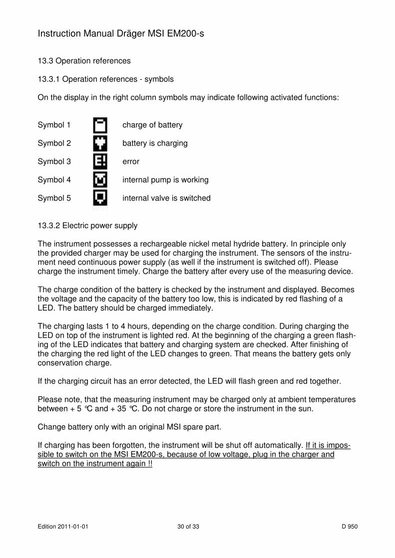
13.3 Operation references 13.3.1 Operation references - symbols On the display in the right column symbols may indicate following activated functions: Symbol 1 charge of battery Symbol 2 battery is charging
Symbol 3 error
Symbol 4 internal pump is working
Symbol 5 internal valve is switched
13.3.2 Electric power supply The instrument possesses a rechargeable nickel metal hydride battery. In principle only the provided charger may be used for charging the instrument. The sensors of the instru-ment need continuous power supply (as well if the instrument is switched off). Please charge the instrument timely. Charge the battery after every use of the measuring device. The charge condition of the battery is checked by the instrument and displayed. Becomes the voltage and the capacity of the battery too low, this is indicated by red flashing of a LED. The battery should be charged immediately. The charging lasts 1 to 4 hours, depending on the charge condition. During charging the LED on top of the instrument is lighted red. At the beginning of the charging a green flash-ing of the LED indicates that battery and charging system are checked. After finishing of the charging the red light of the LED changes to green. That means the battery gets only conservation charge. If the charging circuit has an error detected, the LED will flash green and red together. Please note, that the measuring instrument may be charged only at ambient temperatures between + 5 °C and + 35 °C. Do not charge or store the instrument in the sun. Change battery only with an original MSI spare part. If charging has been forgotten, the instrument will be shut off automatically. If it is impos-sible to switch on the MSI EM200-s, because of low voltage, plug in the charger and switch on the instrument again !!
Instruction Manual Dräger MSI EM200-s
D 950 31 of 33 Edition 2011-01-01
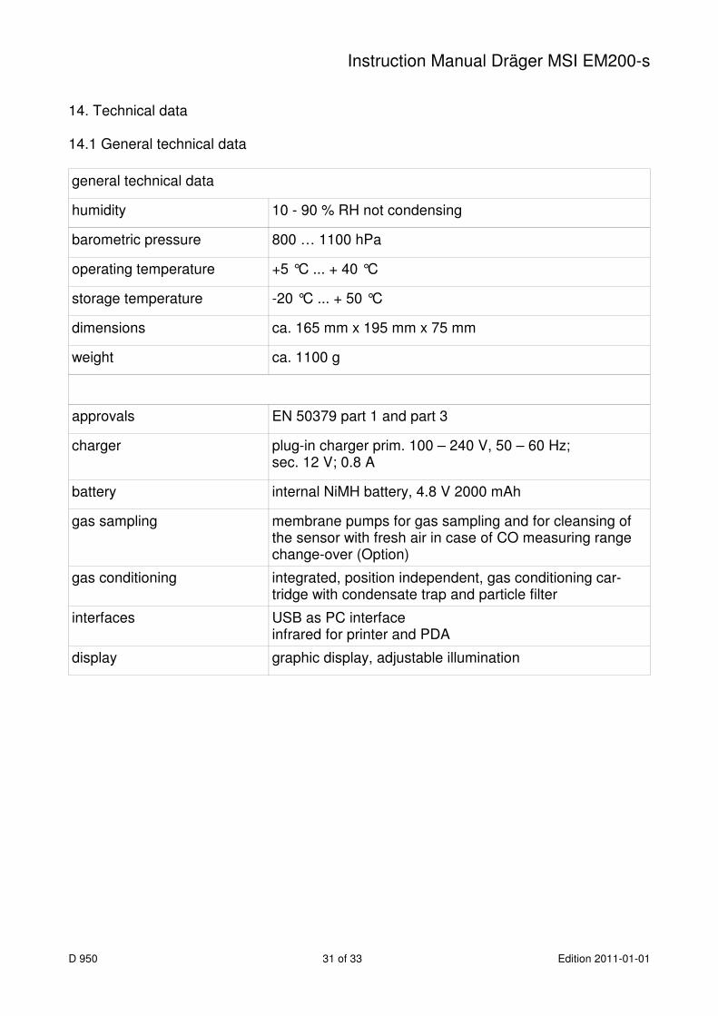
14. Technical data 14.1 General technical data
general technical data
humidity 10 - 90 % RH not condensing
barometric pressure 800 … 1100 hPa
operating temperature +5 °C ... + 40 °C
storage temperature -20 °C ... + 50 °C
dimensions ca. 165 mm x 195 mm x 75 mm
weight ca. 1100 g
approvals EN 50379 part 1 and part 3
charger plug-in charger prim. 100 – 240 V, 50 – 60 Hz; sec. 12 V; 0.8 A
battery internal NiMH battery, 4.8 V 2000 mAh
gas sampling membrane pumps for gas sampling and for cleansing of the sensor with fresh air in case of CO measuring range change-over (Option)
gas conditioning integrated, position independent, gas conditioning car-tridge with condensate trap and particle filter
interfaces USB as PC interface infrared for printer and PDA
display graphic display, adjustable illumination
Instruction Manual Dräger MSI EM200-s
Edition 2011-01-01 32 of 33 D 950
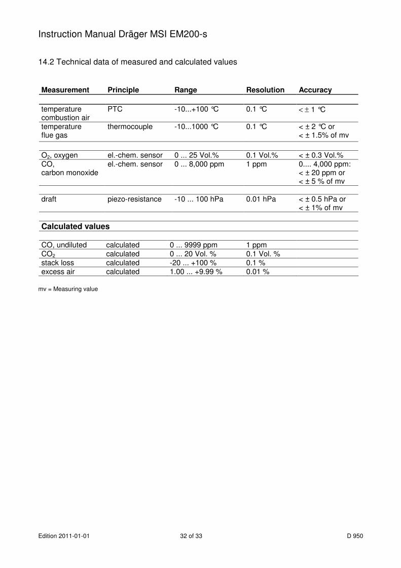
14.2 Technical data of measured and calculated values Measurement Principle Range Resolution Accuracy
temperature combustion air
PTC -10...+100 °C 0.1 °C < ± 1 °C
temperature flue gas
thermocouple -10...1000 °C
0.1 °C < ± 2 °C or < ± 1.5% of mv
O2, oxygen el.-chem. sensor 0 ... 25 Vol.% 0.1 Vol.% < ± 0.3 Vol.% CO, carbon monoxide
el.-chem. sensor 0 ... 8,000 ppm 1 ppm 0.... 4,000 ppm: < ± 20 ppm or < ± 5 % of mv
draft piezo-resistance -10 ... 100 hPa 0.01 hPa < ± 0.5 hPa or
< ± 1% of mv
Calculated values
CO, undiluted calculated 0 ... 9999 ppm 1 ppm CO2 calculated 0 ... 20 Vol. % 0.1 Vol. % stack loss calculated -20 ... +100 % 0.1 % excess air calculated 1.00 ... +9.99 % 0.01 %
mv = Measuring value
Instruction Manual Dräger MSI EM200-s
D 950 33 of 33 Edition 2011-01-01
15. Maintenance and service 15.1 Storing El.-chem. gas sensors react to gases in the ambient, even if the instrument is switched off. Make sure, that the instrument is stored in a place with room temperature without contamination with solvents, exhaust gases or combustibles and that it becomes recharged periodically (once a month). 15.2 Maintenance The gas conditioning cartridge should be cleaned after been in use. In addition to that, the cartridge should be checked due to tightness (O-ring seal). The filter discs and fleece have to be changed if dirty (see 3.4 too). The housing of the instrument can be cleaned with a damp cloth. Take care that the gas outlet at the bottom of the instrument will not get blocked. 15.3 Service In order to assure accurate measurement and the reliability of the functions the MSI EM200-s should be checked according to requirements of EN 50379 and if applicable be calibrated by an authorised service point once a year. 15.4 Consumables and accessories Printer with infra-red data transmission 5600401 Paper for IR-Printer 5690151 Consumable set 2 5600411 consisting of: 10 x disc filter 20 x filter fleece ø 26