embedded system - zero to hero for beginner module
DESCRIPTION
my new embedded system module, this time i try to simplify all the "code readability" and use laymen term as possible as i can. it my first try(not sure) so help me improve it . thanks a lot guys.TRANSCRIPT
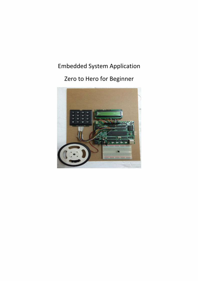
Embedded System Application
Zero to Hero for Beginner

Contents Chapter 1 ..................................................................................................................................................................................................... 3
1.1 The Introduction ................................................................................................................................................................ 3
1.2 Microcontroller Features ............................................................................................................................................... 4
1.3 Microcontroller Architecture ....................................................................................................................................... 8
1.4 Support Component ......................................................................................................................................................... 9
1.5 Transfer the Machine Code/Hex File into the PIC Microcontroller ......................................................... 10
Chapter 2 .................................................................................................................................................................................................. 13
2.1 LED Blinking ..................................................................................................................................................................... 13
2.2 LCD Display ....................................................................................................................................................................... 15
2.2.1 PIC18F4550_Lcddisplay.c (main file) ......................................................................................................... 15
2.2.2 Delay18.c ................................................................................................................................................................. 16
2.2.3 LCD.c .......................................................................................................................................................................... 16
2.2.4 Delay18.h ................................................................................................................................................................. 23
2.2.5 LCD.h.......................................................................................................................................................................... 23
2.2.6 System.h ................................................................................................................................................................... 24
2.3 Analog to Digital Converter ........................................................................................................................................ 26
2.3.1 PIC18F4550_adc.c (main file) ......................................................................................................................... 26
2.3.2 Adc.c//This file provides the functions for the ADC module ........................................................... 27
2.3.2 Adc.h .......................................................................................................................................................................... 28
2.4 Motor Controller ............................................................................................................................................................. 30
2.4.1 PIC18F4550_motorcontrol.c (main file) .................................................................................................... 30
2.5 Keypad ................................................................................................................................................................................. 32
2.5.1 PIC18F4550_keypad.c (main file)................................................................................................................. 32
2.5.2 Keypad.c ................................................................................................................................................................... 33
2.5.3 Keypad.h .................................................................................................................................................................. 35
Chapter 3 .................................................................................................................................................................................................. 36
3.1 Pulse Width Modulation .............................................................................................................................................. 36
3.2 Interrupt ............................................................................................................................................................................. 36
3.2.1 Time Critical Applications ................................................................................................................................ 36
3.2.2 Performing Routine Tasks ............................................................................................................................... 37
3.2.3 Task Switching In Multi-Tasking Applications ....................................................................................... 37
3.2.4 To Service Peripheral Devices Quickly ....................................................................................................... 37
3.3 USB Connection for Communication ...................................................................................................................... 37
References ............................................................................................................................................................................................... 38

Chapter 1
1.1 The Introduction The Embedded System can be use either by microcontroller or by microprocessor,
even though they have a few similarity but both have different in term of data processing performance, price, architecture and its application. This module will only discuss about the microcontroller.
A microcontroller is a type of microprocessor furnished in a single integrated circuit and needing a minimum of support chips. Its principal nature is self-sufficiency and low cost. It is not intended to be used as a computing device in the conventional sense; that is, a microcontroller is not designed to be a data processing machine, but rather an intelligent core for a specialized dedicated system.
Microcontrollers are embedded in many control, monitoring, and processing systems. Some are general-purpose devices but most microcontrollers are used in specialized systems such as washing machines, microwave ovens, automobiles of many kinds. A microcontroller usually includes a central processor, input and output ports, memory for program and data storage, an internal clock, and one or more peripheral devices such as timers, counters, analog-to-digital converters, serial communication facilities, and watchdog circuits[1].
Microcontrollers have traditionally been programmed using the assembly language of the target device. Although the assembly language is fast, it has several disadvantages. An assembly program consists of mnemonics, which makes learning and maintaining a program written using the assembly language difficult. Also, microcontrollers manufactured by different firms have different assembly languages, so the user must learn a new language with every new microcontroller he or she uses.
Microcontrollers can also be programmed using a high-level language, such as BASIC, PASCAL, or C. High-level languages are much easier to learn than assembly languages. They also facilitate the development of large and complex programs. In this book we shall be learning the programming of PIC microcontrollers using the popular C.
In theory, a single chip is sufficient to have a running microcontroller system. In practical applications, however, additional components may be required so the microcomputer can interface with its environment. With the advent of the PIC family of microcontrollers the development time of an electronic project has been reduced to several hours[2].
Basically, a microcomputer executes a user program which is loaded in its program memory. Under the control of this program, data is received from external devices (inputs), manipulated, and then sent to external devices (outputs).
In this module, the author decides to use the microcontroller from Microchip Technology. The Peripheral Interface Controller also known as PIC microcontroller. To understand the software and hardware of a microcontroller-based system, one must first master some very basic concepts underlying computer design.
1.2 Microcontroller Features
1.2.1 Supply Voltage Most microcontrollers operate with the standard logic voltage of 5V. Some
microcontrollers can operate at as low as 2.7V, and some will tolerate 6V without any problem. The manufacturer’s data sheet will have information about the allowed limits of the power supply voltage.
Usually, a voltage regulator circuit is used to obtain the required power supply
voltage when the device is operated from a mains adapter or batteries. For example, a 5V regulator is required if the microcontroller is operated from a 5V supply using a 9V battery.
1.2.2 The Clock All microcontrollers require a clock (or an oscillator) to operate, usually
provided by external timing devices connected to the microcontroller. In most cases, these external timing devices are a crystal plus two small capacitors. In some cases they are resonators or an external resistor-capacitor pair. Some microcontrollers have built-in timing circuits and do not require external timing components. If an application is not time-sensitive, external or internal (if available) resistor-capacitor timing components are the best option for their simplicity and low cost.
An instruction is executed by fetching it from the memory and then decoding it. This usually takes several clock cycles and is known as the instruction cycle. In PIC microcontrollers, an instruction cycle takes four clock periods. Thus the microcontroller operates at a clock rate that is one-quarter of the actual oscillator frequency. The PIC18F series of microcontrollers can operate with clock frequencies up to 40MHz.
1.2.3 Timers
Timers are important parts of any microcontroller. A timer is basically a counter which is driven from either an external clock pulse or the microcontroller’s internal oscillator. A timer can be 8 bits or 16 bits wide. Data can be loaded into a timer under program control, and the timer can be stopped or started by program control. Most timers can be configured to generate an interrupt when they reach a certain count (usually when they overflow). The user program can use an interrupt to carry out accurate timing-related operations inside the microcontroller. Microcontrollers in the PIC18F series have at least three timers.
Some microcontrollers offer capture and compare facilities, where a timer value can be read when an external event occurs, or the timer value can be compared to a pre-set value, and an interrupt is generated when this value is reached. Most PIC18F microcontrollers have at least two capture and compare modules.
1.2.4 Watchdog
Most microcontrollers have at least one watchdog facility. The watchdog is basically a timer that is refreshed by the user program. Whenever the program fails to refresh the watchdog, a reset occurs. The watchdog timer is used to detect a system problem, such as the program being in an endless loop. This safety feature prevents runaway software and stops the microcontroller from executing meaningless and
unwanted code. Watchdog facilities are commonly used in real-time systems where the successful termination of one or more activities must be checked regularly.
1.2.5 Reset Input
Reset input is used to reset a microcontroller externally. Resetting puts the microcontroller into a known state such that the program execution starts from address 0 of the program memory. An external reset action is usually achieved by connecting a push-button switch to the reset input. When the switch is pressed, the microcontroller is reset.
1.2.6 Interrupts
Interrupts are an important concept in microcontrollers. An interrupt causes the microcontroller to respond to external and internal (e.g., a timer) events very quickly. When an interrupt occurs, the microcontroller leaves its normal flow of program execution and jumps to a special part of the program known as the interrupt service routine (ISR). The program code inside the ISR is executed, and upon return from the ISR the program resumes its normal flow of execution.
The ISR starts from a fixed address of the program memory sometimes known as the interrupt vector address. Some microcontrollers with multi-interrupt features have just one interrupt vector address, while others have unique interrupt vector addresses, one for each interrupt source. Interrupts can be nested such that a new interrupt can suspend the execution of another interrupt. Another important feature of multi-interrupt capability is that different interrupt sources can be assigned different levels of priority. For example, the PIC18F series of microcontrollers has both low-priority and high priority interrupts levels.
1.2.7 Brown-out Reset/Detector
Brown-out detectors, which are common in many microcontrollers, reset the microcontroller if the supply voltage falls below a nominal value. These safety features can be employed to prevent unpredictable operation at low voltages, especially to protect the contents of EEPROM-type memories.
1.2.8 Analog to Digital Converter
An analog-to-digital converter (A/D) is used to convert an analog signal, such as voltage, to digital form so a microcontroller can read and process it. Some microcontrollers have built-in A/D converters. External A/D converter can also be connected to any type of microcontroller. A/D converters are usually 8 to 10 bits, having 256 to 1024 quantization levels. Most PIC microcontrollers with A/D features have multiplexed A/D converters which provide more than one analog input channel.
The A/D conversion process must be started by the user program and may take several hundred microseconds to complete. A/D converters usually generate interrupts when a conversion is complete so the user program can read the converted data quickly. A/D converters are especially useful in control and monitoring applications, since most sensors (e.g., temperature sensors, pressure sensors, force sensors, etc.) produce analog output voltages.

1.2.9 Serial Input Output Serial communication (also called RS232 communication) enables a
microcontroller to be connected to another microcontroller or to a PC using a serial cable. Some microcontrollers have built-in hardware called USART (universal synchronous asynchronous receiver-transmitter) to implement a serial communication interface.
The user program can usually select the baud rate and data format. If no serial input-output hardware is provided, it is easy to develop software to implement serial data communication using any I/O pin of a microcontroller. The PIC18F series of microcontrollers has built-in USART modules. We shall see in Chapter 6 how to write mikroC programs to implement serial communication with and without a USART module.
Some microcontrollers (e.g., the PIC18F series) incorporate SPI (serial peripheral interface) or I2C (integrated interconnect) hardware bus interfaces. These enable a microcontroller to interface with other compatible devices easily.
1.2.10 EEPROM Data Memory
EEPROM-type data memory is also very common in many microcontrollers. The advantage of an EEPROM memory is that the programmer can store non-volatile data there and change this data whenever required. For example, in a temperature monitoring application, the maximum and minimum temperature readings can be stored in an EEPROM memory.
If the power supply is removed for any reason, the values of the latest readings are available in the EEPROM memory. The PIC18F452 microcontroller has 256 bytes of EEPROM memory. Other members of the PIC18F family have more EEPROM memory (e.g., the PIC18F6680 has 1024 bytes).
1.2.11 Sleep Mode
Some microcontrollers (e.g., PICs) offer built-in sleep modes, where executing this instruction stops the internal oscillator and reduces power consumption to an extremely low level. The sleep mode’s main purpose is to conserve battery power when the microcontroller is not doing anything useful. The microcontroller is usually woken up from sleep mode by an external reset or a watchdog time-out.
1.2.12 Power-On Reset
Some microcontrollers (e.g., PICs) have built-in power-on reset circuits which keep the microcontroller in the reset state until all the internal circuitry has been initialized. This feature is very useful, as it starts the microcontroller from a known state on power-up. An external reset can also be provided, where the microcontroller is reset when an external button is pressed.
1.2.13 Low Power Operation
Low-power operation is especially important in portable applications where microcontroller-based equipment is operated from batteries. Some microcontrollers (e.g., PICs) can operate with less than 2mA with a 5V supply, and around 15mA at a 3V supply. Other microcontrollers, especially microprocessor-based systems with several chips, may consume several hundred milliamperes or even more.

1.2.14 Current Sink/Source Capability
Current sink/source capability is important if the microcontroller is to be connected to an external device that might draw a large amount of current to operate. PIC microcontrollers can source and sink 25mA of current from each output port pin. This current is usually sufficient to drive LEDs, small lamps, buzzers, small relays, etc. The current capability can be increased by connecting external transistor switching circuits or relays to the output port pins.
1.2.15 Usb Interface
USB is currently a very popular computer interface specification used to connect various peripheral devices to computers and microcontrollers. Some PIC microcontrollers provide built-in USB modules. The PIC18F2x50, for example, has built-in USB interface capabilities.
1.2.16 Motor Controller
Some PIC microcontrollers, for example the PIC18F2x31, provide motor control interface capability.
1.2.17 CAN Interface
CAN bus is a very popular bus system used mainly in automation applications. Some PIC18F-series microcontrollers (e.g., the PIC18F4680) provide CAN interface capability.
1.2.18 Ethernet Interface
Some PIC microcontrollers (e.g., the PIC18F97J60) provide Ethernet interface capabilities and thus are easily used in network-based applications.

1.3 Microcontroller Architecture This module use PIC18F4550 as the main reference as our trainer board also use the same microcontroller model. The right place to learn the microcontroller architecture is the datasheet. The ability to read the datasheet can be developing through experience but in reality, it is really not that hard to understand a technical paper.
Figure 1: PDIP model for PIC18F4550 pin mapping
Figure 1 show the pin mapping for the PIC18F4550 model PDIP, which have 40 pin. In summary, based on datasheet, the PIC18F4550 microcontroller has 5 input/output ports (PORTA, PORTB, PORTC, PORTD and PORTE), 4 timers, 13 channels or pin for 10-bit analog to digital module, 1 compare/capture/PWM module and support USB module.

1.4 Support Component
The PIC microcontroller might operate by its own, but to get higher level of efficiency, the support components become a compulsory. The following are a few scenarios which are quite popular related with the embedded system circuit design.
1.4.1 External Reset Circuit
Figure 2: External Reset Circuit
Figure 2 above show how the external reset for PIC microcontroller can be done. To use this feature, the user must enable the Master Clean Reset, MCLR configuration in the config word setting. This feature will give the user to hard reset the embedded system. For details of this feature, look at page 47 on PIC18F4550 datasheet.
1.4.2 Crystal Oscillator Operation and Setting
Figure 3: Circuit for Crystal Oscillator
Figure 3 shows how a crystal is connected to the microcontroller. The capacitor values depend on the mode of the crystal and the selected frequency. Table 2.4 gives the
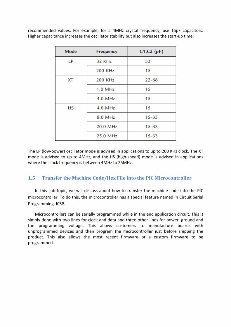
recommended values. For example, for a 4MHz crystal frequency, use 15pF capacitors. Higher capacitance increases the oscillator stability but also increases the start-up time.
The LP (low-power) oscillator mode is advised in applications to up to 200 KHz clock. The XT mode is advised to up to 4MHz, and the HS (high-speed) mode is advised in applications where the clock frequency is between 4MHz to 25MHz.
1.5 Transfer the Machine Code/Hex File into the PIC Microcontroller
In this sub-topic, we will discuss about how to transfer the machine code into the PIC microcontroller. To do this, the microcontroller has a special feature named In Circuit Serial Programming, ICSP.
Microcontrollers can be serially programmed while in the end application circuit. This is simply done with two lines for clock and data and three other lines for power, ground and the programming voltage. This allows customers to manufacture boards with unprogrammed devices and then program the microcontroller just before shipping the product. This also allows the most recent firmware or a custom firmware to be programmed.
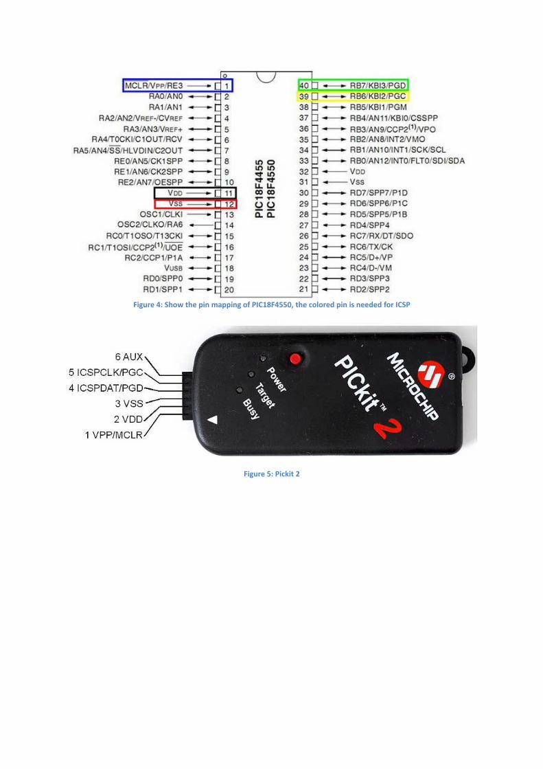
Figure 4: Show the pin mapping of PIC18F4550, the colored pin is needed for ICSP
Figure 5: Pickit 2

Figure 6: Show a connection between Pickit 2 and PIC microcontroller
For model PIC18 and above, there are a few method to transfer generated machine code into the microcontroller, other method is using the bootloader.

Chapter 2
In this chapter, we will discuss a few sample programmes for PIC microcontroller. A brief explanation for the written programme is use for better understanding. Before we start, it is strongly recommended that the reader has a basic understanding of C language, numbering format, digital system and know how to read electronic schematic diagram.
For all sample program shown in this guide, we use the same template for all application and modify the template only for specific need application like definition of variables, port direction depend on application and others that relevant. We would like to recommend making 1 file for 1 application, like 1 file specific only for adc function or 1 for lcd display only. This is for code maintenance or upgrade or for better understanding for other people while look at our coding.
2.1 LED Blinking // This is a sample program written for SeST Board@PMJ // PIC18F4550 + led blinking // used C language // MPLAB IDE v8.92 // MPLAB C18 V3.46 compiler // Last Updated date: 11 March 2015 // Embedded System Applications - Zero to Hero for Beginner #include <p18f4550.h> //include the PIC18F model of PIC header file //config word #pragma config FOSC = HS // Maximum Fosc is 48MHz, so if 20MHz external crystal is used, need to select HS #pragma config PWRT = ON // Power Up Timer Enable bit #pragma config BOR = OFF // Brown-out Reset Enable bits #pragma config WDT = OFF // Watch-Dog Timer Enable bit #pragma config PBADEN = ON // PORTB analog pin as analog input after Reset #pragma config MCLRE = ON // MCLR pin enable, RE3 input disabled #pragma config LVP = OFF // Low voltage programming disable //fucntion prototype void Delay1KTCYx( unsigned char unit ); //global variables #define _XTAL_FREQ 20000000 //result in Fosc to 20MHz with 20MHz Crystal //main fucntion void main(void) { // ensure all the hardware port in zero initially PORTD = 0; // Initialize the I/O port direction. TRISD = 0; while (1) { PORTD = 0xFF; //turn on all led on port D Delay10KTCYx(2000); //delay for 200 k cycle PORTD = 0; //turn off all led on port D Delay10KTCYx(2000); //delay for 200 k cycle
When a line start with ‘//’, it will be ignored by the compiler because it is a comment.
Include header/system file. In this case, we include the system file for the microcontroller model we use.
Specific setting for microcontroller. See configuration word setting section within the microcontroller datasheet.
Every function except the main function must be declared before the main function.
Variables that can be used for all function
The main function. The name must be ‘main’.
To make sure no initial value registered in port D
A port direction instruction. Set 0 for output, 1 for input. Apply to all pin in port D.
Instruction for infinity looping This instruction will continue
until power been cut-off. See comment for each line.
} // while (1) }// main
Figure 7: schematic diagram for pic18f4550 with led, crystal oscillator and external reset button.
PIC18F4550
Crystal oscillator
capacitor
This connections setup is for external reset button. R1 value must be higher than R2 value, thus if switch is pressed, the MCLR pin will be grounded and the pic microcontroller being reset.
R3 to R10 is a protective resistor, its protect the LED from the over current.
Normal value range between 220 ohm to 1k ohm. Depend on application and type of
LED.
LED for indicator. Connected to port D at
PIC microcontroller.

2.2 LCD Display 2.2.1 PIC18F4550_Lcddisplay.c (main file) // This is a sample program written for SeST Board@PMJ // PIC18F4550 + LCD display // used C language // MPLAB IDE v8.92 // MPLAB C18 V3.46 compiler // Last Updated date: 11 March 2015 // Embedded System Applications - Zero to Hero for Beginner //include files #include <p18f4550.h> //include the PIC18F model of PIC header file #include "delay18.h" //include the delay functions #include "system.h" //include system header file #include "lcd.h" //include lcd functions header file //config word #pragma config FOSC = HS // Maximum Fosc is 48MHz, so if 20MHz external crystal is used, need to select HS #pragma config PWRT = ON // Power Up Timer Enable bit #pragma config BOR = OFF // Brown-out Reset Enable bits #pragma config WDT = OFF // Watch-Dog Timer Enable bit #pragma config PBADEN = ON // PORTB analog pin as analog input after Reset #pragma config MCLRE = ON // MCLR pin enable, RE3 input disabled #pragma config LVP = OFF // Low voltage programming disable //global variables rom const char string_poli[] = " Politeknik\n Mersing"; //main fucntion void main(void) { PORTA = 0; PORTB = 0; PORTC = 0; PORTD = 0; PORTE = 0; // Initialize the I/O port direction. TRISA = 0b00010001; TRISB = 0b00001111; TRISC = 0b10010011; TRISD = 0; TRISE = 0; // Initialize the LCD. lcd_initialize(); // Display message lcd_clear_msg(string_poli); //display poli name delay_ms(500); //wait for ~2s //infinity looping //while (1) // {
Port direction can also be used to assign specific pin in the port.
Instruction for the function named lcd_initialze to start operation/run.
This function will start to operate/run after the previous instruction has been successfully completed.
The delay18.h, system.h and lcd.h are made by the programmer to assist the main file. This separation has advantage during troubleshoot and code maintenances.
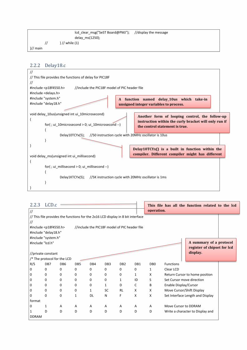
lcd_clear_msg("SeST Board@PMJ"); //display the message delay_ms(1250); // } // while (1) }// main
2.2.2 Delay18.c // // This file provides the functions of delay for PIC18F // #include <p18f4550.h> //include the PIC18F model of PIC header file #include <delays.h> #include "system.h" #include "delay18.h" void delay_10us(unsigned int ui_10microsecond) { for( ; ui_10microsecond > 0; ui_10microsecond --) { Delay10TCYx(5); //50 instruction cycle with 20MHz oscillator is 10us } } void delay_ms(unsigned int ui_millisecond) { for( ; ui_millisecond > 0; ui_millisecond --) { Delay1KTCYx(5); //5K instruction cycle with 20MHz oscillator is 1ms
} }
2.2.3 LCD.c // // This file provides the functions for the 2x16 LCD display in 8 bit interface // #include <p18f4550.h> //include the PIC18F model of PIC header file #include "delay18.h" #include "system.h" #include "lcd.h" //private constant /* The protocol for the LCD R/S DB7 DB6 DB5 DB4 DB3 DB2 DB1 DB0 Functions 0 0 0 0 0 0 0 0 1 Clear LCD 0 0 0 0 0 0 0 1 X Return Cursor to home position 0 0 0 0 0 0 1 ID S Set Cursor move direction 0 0 0 0 0 1 D C B Enable Display/Cursor 0 0 0 0 1 SC RL X X Move Cursor/Shift Display 0 0 0 1 DL N F X X Set Interface Length and Display format 0 1 A A A A A A A Move Cursor to DDRAM 1 D D D D D D D D Write a character to Display and DDRAM
A function named delay_10us which take-in unsigned integer variables to process.
Delay10TCYx() is a built in function within the compiler. Different compiler might has different
Another form of looping control, the follow-up instruction within the curly bracket will only run if the control statement is true.
This file has all the function related to the lcd operation.
A summary of a protocol register of chipset for lcd display.
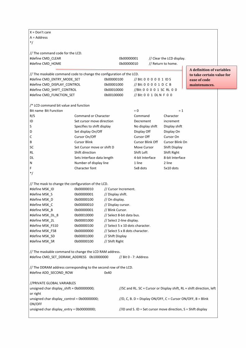
X = Don't care A = Address */ // The command code for the LCD. #define CMD_CLEAR 0b00000001 // Clear the LCD display. #define CMD_HOME 0b00000010 // Return to home. // The maskable command code to change the configuration of the LCD. #define CMD_ENTRY_MODE_SET 0b00000100 // Bit: 0 0 0 0 0 1 ID S #define CMD_DISPLAY_CONTROL 0b00001000 // Bit: 0 0 0 0 1 D C B #define CMD_SHIFT_CONTROL 0b00010000 //Bit: 0 0 0 0 1 SC RL 0 0 #define CMD_FUNCTION_SET 0b00100000 // Bit: 0 0 1 DL N F 0 0 /* LCD command bit value and function Bit name Bit Function = 0 = 1 R/S Command or Character Command Character ID Set cursor move direction Decrement increment S Specifies to shift display No display shift Display shift D Set display On/Off Display Off Display On C Cursor On/Off Cursor Off Cursor On B Cursor Blink Cursor Blink Off Cursor Blink On SC Set Cursor move or shift D Move Cursor Shift Display RL Shift direction Shift Left Shift Right DL Sets Interface data length 4-bit Interface 8-bit Interface N Number of display line 1 line 2 line F Character font 5x8 dots 5x10 dots */ // The mask to change the configuration of the LCD. #define MSK_ID 0b00000010 // Cursor Increment. #define MSK_S 0b00000001 // Display shift. #define MSK_D 0b00000100 // On display. #define MSK_C 0b00000010 // Display cursor. #define MSK_B 0b00000001 // Blink Cursor. #define MSK_DL_8 0b00010000 // Select 8-bit data bus. #define MSK_2L 0b00001000 // Select 2-line display. #define MSK_F510 0b00000100 // Select 5 x 10 dots character. #define MSK_F58 0b00000000 // Select 5 x 8 dots character. #define MSK_SD 0b00001000 // Shift Display #define MSK_SR 0b00000100 // Shift Right // The maskable command to change the LCD RAM address. #define CMD_SET_DDRAM_ADDRESS 0b10000000 // Bit 0 - 7: Address // The DDRAM address corresponding to the second row of the LCD. #define ADD_SECOND_ROW 0x40 //PRIVATE GLOBAL VARIABLES unsigned char display_shift = 0b00000000; //SC and RL. SC = Cursor or Display shift, RL = shift direction, left or right unsigned char display_control = 0b00000000; //D, C, B. D = Display ON/OFF, C = Cursor ON/OFF, B = Blink ON/OFF unsigned char display_entry = 0b00000000; //ID and S. ID = Set cursor move direction, S = Shift display
A definition of variables to take certain value for ease of code maintenances.
//PRIVATE FUNCTION PROTOTYPES void send_lcd_data(unsigned char b_rs, unsigned char uc_data); void set_lcd_e(unsigned char b_output); void set_lcd_rs(unsigned char b_output); void set_lcd_data(unsigned char uc_data); void lcd_initialize(void) { // Set the LCD E pin and wait for the LCD to be ready before we // start sending data to it. set_lcd_e(1); delay_ms(15); //delay 15ms for LCD to start up // Configure the Function Set of the LCD. send_lcd_data(0, CMD_FUNCTION_SET | MSK_DL_8 | MSK_2L | MSK_F58); // Configure the entry mode set of the LCD. display_entry = MSK_ID & ~MSK_S; send_lcd_data(0, CMD_ENTRY_MODE_SET | display_entry); // Configure the display on/off control of the LCD. display_control = MSK_D & ~MSK_C & ~MSK_B; send_lcd_data(0, CMD_DISPLAY_CONTROL | display_control); display_shift = MSK_SD | MSK_SR; // Clear the LCD display. lcd_clear(); } void lcd_config(unsigned char uc_config) { send_lcd_data(0, uc_config); } void lcd_clear(void) { // Send the command to clear the LCD display. send_lcd_data(0, CMD_CLEAR); } void lcd_home(void) { // Send the command to return the cursor to the home position. send_lcd_data(0, CMD_HOME); } void lcd_2ndline(void) { // Send the command to jump to the second row. send_lcd_data(0, CMD_SET_DDRAM_ADDRESS | ADD_SECOND_ROW); } void lcd_goto(unsigned char uc_position) { // Send the command to jump to the defined position.
This function is to make sure the lcd display is ready to operate with our setting.
send_lcd_data(0, CMD_SET_DDRAM_ADDRESS | uc_position); } void lcd_putchar(char c_data) { // Send the data to display. send_lcd_data(1, (unsigned char)c_data); } void lcd_putstr(rom const char* csz_string) { // Loop until the end of string. while (*csz_string != '\0') { // Jump to the second row if '\n' or '\r' is found. if (*csz_string == '\n' || *csz_string == '\r') { lcd_2ndline(); } // Else, display the character. else { lcd_putchar(*csz_string); } // Point to next character. csz_string++; } } void lcd_bcd(unsigned char uc_digit, unsigned int ui_number) { unsigned int ui_decimal[5] ={ 0 }; //extract 5 single digit from ui_number ui_decimal[4] = ui_number/10000; // obtain the largest single digit, digit4 ui_decimal[3] = ui_number%10000; // obtain the remainder ui_decimal[2] = ui_decimal[3]%1000; ui_decimal[3] = ui_decimal[3]/1000; // obtain the 2nd largest single digit, digit3 ui_decimal[1] = ui_decimal[2]%100; ui_decimal[2] = ui_decimal[2]/100; // obtain the 3rd largest single digit, digit2 ui_decimal[0] = ui_decimal[1]%10; // obtain the smallest single digit, digit0 ui_decimal[1] = ui_decimal[1]/10; // obtain the 4th largest single digit, digit1 if (uc_digit > 5) uc_digit = 5; // limit to 5 digits only for( ; uc_digit > 0; uc_digit--) { lcd_putchar(ui_decimal[uc_digit - 1] + 0x30); } } void lcd_binary(unsigned char uc_digit, unsigned char uc_number) { unsigned char i; if(uc_digit > 0) { for(i = uc_digit; i > 0; i--) {
A function to convert the data into bcd numbering format
lcd_putchar((0b00000001 & ( uc_number>> (i-1))) + '0'); } } } void lcd_float(unsigned char uc_digit, float f_value) { unsigned char uc_decimal[6] ={ 0 }; unsigned long int ui_temp = 0; //temporary register unsigned char i , j; //extract 6 single digit from f_value if(f_value <= 999.999) // the maximum float this function can convert { ui_temp =(unsigned long int) f_value; //cast the float value without round up uc_decimal[5] = ui_temp/100; uc_decimal[4] = ui_temp%100; // obtain the remainder uc_decimal[3] = uc_decimal[4]%10; // obtain the least significant digit before floating point uc_decimal[4] = uc_decimal[4]/10; //obtain the 1st digit, Most Significant digit //floating point value, maximum is 3 digit after floating point, in milli value ui_temp = ((unsigned int)(f_value * 1000))%1000; //get the 3 digit value after floating point, convert to integer uc_decimal[2] = ui_temp/100; uc_decimal[1] = ui_temp%100; uc_decimal[0] = uc_decimal[1]%10; // obtain the smallest single digit, digit0 uc_decimal[1] = uc_decimal[1]/10; // obtain the 4th largest single digit, digit1 if(uc_decimal[5] != 0) { lcd_putchar(uc_decimal[5] + '0'); lcd_putchar(uc_decimal[4] + '0'); } else if (uc_decimal[4] != 0) lcd_putchar(uc_decimal[4] + '0'); //display 1st digit, MS digit lcd_putchar(uc_decimal[3] + '0'); //display 2nd digit before floating point lcd_putchar('.'); //display "dot" to lcd if(uc_digit == 0) uc_digit = 1; // minimum need to display 1 digit after floating point j= 0; for(i=3; i>0; i--) //display the digit after floating point { lcd_putchar(uc_decimal[i-1] + 0x30); j++; if(j== uc_digit) break; // break from for loop } if(uc_decimal[4] == 0) lcd_putchar(' '); } else lcd_putstr("Over"); //display message to indicate the value is too big to convert } void lcd_clear_msg(rom const char* csz_string) { lcd_clear(); lcd_putstr(csz_string); }

void lcd_error_trap(rom const char* csz_string) { char i; // Display the error messages and trap the error. lcd_clear_msg(csz_string); for ( i = 0; i < 20; i ++) { //Delay10KTCYx(50); //10K instruction cycle is 1ms delay for 40MHz Fosc delay_ms(50); } //create delay for ~2 seconds /*for ( i = 0; i < 15; i ++) { Delay10KTCYx(50); //10K instruction cycle is 1ms delay for 40MHz Fosc } */ delay_ms(2000); //while (1); } void lcd_1stline_msg(rom const char* csz_string) { unsigned char i = 0; lcd_home(); while (*csz_string != '\0') { i++; lcd_putchar(*csz_string++); } for(; i<16;i++) lcd_putchar(' '); //append the rest of space with "space" } void lcd_2ndline_msg(rom const char* csz_string) { unsigned char i = 0; lcd_2ndline(); while (*csz_string != '\0') { i++; lcd_putchar(*csz_string++); } for(; i<16;i++) lcd_putchar(' '); //append the rest of space with "space" } void send_lcd_data(unsigned char b_rs, unsigned char uc_data) { // 8-bit Mode only need to send the data once. set_lcd_rs(b_rs); set_lcd_data(uc_data); // Send a positive e pulse. set_lcd_e(1); delay_ms(1); set_lcd_e(0); delay_ms(2); // make the default stage to logic low

set_lcd_rs(0); set_lcd_data(0); } void set_lcd_e(unsigned char b_output) { LCD_E = b_output; } void set_lcd_rs(unsigned char b_output) { LCD_RS = b_output; } void set_lcd_data(unsigned char uc_data) { LCD_DATA = uc_data; } void lcd_display(void) { display_control |= MSK_D; lcd_config(CMD_DISPLAY_CONTROL | display_control); } void lcd_no_display(void) { display_control &= ~MSK_D; lcd_config(CMD_DISPLAY_CONTROL | display_control); } void lcd_cursor(void) { display_control |= MSK_C; lcd_config(CMD_DISPLAY_CONTROL | display_control); } void lcd_no_cursor(void) { display_control &= ~MSK_C; lcd_config(CMD_DISPLAY_CONTROL | display_control); } void lcd_cursor_blink(void) { display_control |= MSK_B; lcd_config(CMD_DISPLAY_CONTROL | display_control); } void lcd_no_blink(void) { display_control &= ~MSK_B; lcd_config(CMD_DISPLAY_CONTROL | display_control); } void lcd_shift_left(void) {
lcd_config(CMD_SHIFT_CONTROL | MSK_SD & ~MSK_SR); } void lcd_shift_right(void) { lcd_config(CMD_SHIFT_CONTROL | MSK_SD | MSK_SR); } void lcd_left_to_right(void) { display_entry |= MSK_ID; lcd_config( CMD_ENTRY_MODE_SET | display_entry); } void lcd_right_to_left(void) { display_entry &= ~MSK_ID; lcd_config( CMD_ENTRY_MODE_SET | display_entry); } void lcd_autoscroll(void) { display_entry |= MSK_S; lcd_config( CMD_ENTRY_MODE_SET | display_entry); } void lcd_no_autoscroll(void) { display_entry &= ~MSK_S; lcd_config( CMD_ENTRY_MODE_SET | display_entry); }
2.2.4 Delay18.h #ifndef _DELAY18_H #define _DELAY18_H void delay_10us(unsigned int ui_10microsecond); void delay_ms(unsigned int ui_millisecond); #endif
2.2.5 LCD.h #ifndef _LCD_H #define _LCD_H extern void lcd_initialize(void); extern void lcd_config(unsigned char uc_config); extern void lcd_clear(void); extern void lcd_home(void); extern void lcd_2ndline(void); extern void lcd_goto(unsigned char uc_position); extern void lcd_putchar(char c_data); extern void lcd_putstr(rom const char* csz_string); extern void lcd_bcd(unsigned char uc_digit, unsigned int ui_number); extern void lcd_binary(unsigned char uc_digit, unsigned char uc_number);
Contain function prototype for every function define in delay18.c
If lcd.h hasn’t been define yet, this instruction will define it. Precautious measure.

void lcd_float(unsigned char uc_digit, float f_value); extern void lcd_clear_msg(rom const char* csz_string); extern void lcd_error_trap(rom const char* csz_string); extern void lcd_1stline_msg(rom const char* csz_string); extern void lcd_2ndline_msg(rom const char* csz_string); extern void lcd_display(void); extern void lcd_no_display(void); extern void lcd_cursor(void); extern void lcd_no_cursor(void); extern void lcd_cursor_blink(void); extern void lcd_no_blink(void); extern void lcd_shift_left(void); extern void lcd_shift_right(void); extern void lcd_left_to_right(void); extern void lcd_right_to_left(void); extern void lcd_autoscroll(void); extern void lcd_no_autoscroll(void); #endif
2.2.6 System.h // This is the header file that describes the system properties for SeST Board program // Oscillator Frequency, #define _XTAL_FREQ 20000000 // result in Fosc to 20MHz with 20MHz Crystal // I/O Connections. // Parallel 2x16 Character LCD #define LCD_E LATAbits.LATA3 // E clock pin is connected to RA3 #define LCD_RS LATAbits.LATA2 // RS pin is used for LCD to differentiate data is command or character, RA2 #define LCD_BACKLIGHT LATAbits.LATA1 // Back light of LCD, active high, connected to RA1 #define LCD_DATA LATD // Data Latch of LCD is connected to PORTD, 8 bit mode // DB7(LCD) = RD7(PIC) // DB6(LCD) = RD6(PIC) // DB5(LCD) = RD5(PIC) // DB4(LCD) = RD4(PIC) // DB3(LCD) = RD3(PIC) // DB2(LCD) = RD2(PIC) // DB1(LCD) = RD1(PIC) // DB0(LCD) = RD0(PIC)
This is a function prototype for every function define in lcd.c. The word ‘extern’ means that the availability of this function is for all file in the project.
The system.h file contain the global variables for the project. This file is optional, all these variable can also be written within the main file. The purpose of this file is for the ease of code maintenance.
This is the control pins for lcd display.
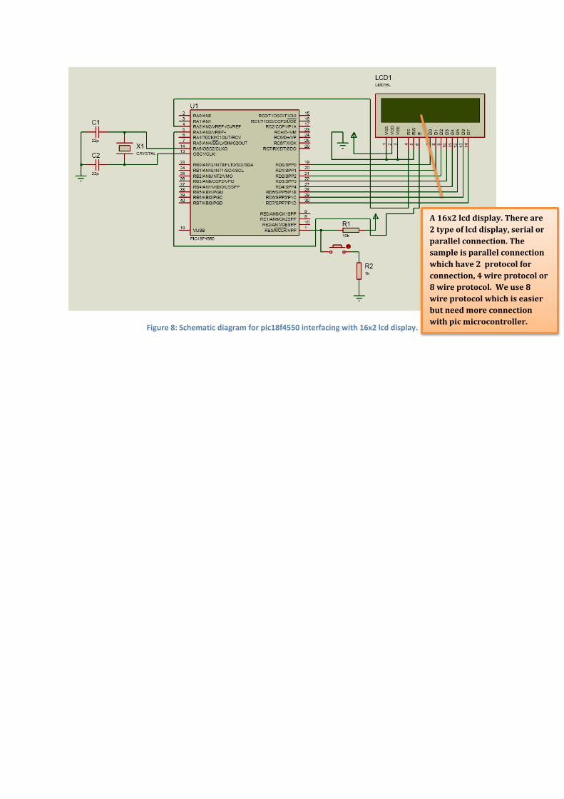
Figure 8: Schematic diagram for pic18f4550 interfacing with 16x2 lcd display.
A 16x2 lcd display. There are 2 type of lcd display, serial or parallel connection. The sample is parallel connection which have 2 protocol for connection, 4 wire protocol or 8 wire protocol. We use 8 wire protocol which is easier but need more connection with pic microcontroller.

2.3 Analog to Digital Converter 2.3.1 PIC18F4550_adc.c (main file) // This is a sample program written for SeST Board@PMJ // PIC18F4550 + LCD display + LM35 // used C language // MPLAB IDE v8.92 // MPLAB C18 V3.46 compiler // Last Updated date: 11 March 2015 // Embedded System Applications - Zero to Hero for Beginner #include <p18f4550.h> //include the PIC18F model of PIC header file #include "delay18.h" //include the delay functions #include "system.h" //include system header file #include "adc.h" //include adc functions header file #include "lcd.h" //include lcd functions header file //config word #pragma config FOSC = HS // Maximum Fosc is 48MHz, so if 20MHz external crystal is used, need to select HS #pragma config PWRT = ON // Power Up Timer Enable bit #pragma config BOR = OFF // Brown-out Reset Enable bits #pragma config WDT = OFF // Watch-Dog Timer Enable bit #pragma config PBADEN = ON // PORTB analog pin as analog input after Reset #pragma config MCLRE = ON // MCLR pin enable, RE3 input disabled #pragma config LVP = OFF // Low voltage programming disable //function prototype void test_adc(void); //global variable rom const char string_poli[] = " Politeknik\n Mersing"; //main fuction void main(void) { // ensure all the hardware port in zero initially PORTA = 0; PORTB = 0; PORTC = 0; PORTD = 0; PORTE = 0; // Initialize the I/O port direction. TRISA = 0b00010001; TRISB = 0b00001111; TRISC = 0b10010011; TRISD = 0; TRISE = 0; // Initialize ADC. adc_initialize(); // Initialize the LCD. lcd_initialize(); // Display message
Before we can use adc feature, a few setup has to be made. This function is for that reason.
We must write the instruction that we want to operate in the main file only. Only instruction within the main function will be run.

lcd_clear_msg(string_poli); //display poli name delay_ms(500); //wait for ~2s //infinity looping while (1) { lcd_clear_msg("SeST Board@PMJ"); //display the message delay_ms(500); //wait for ~2s test_adc(); } // while (1) }// main //adc function void test_adc(void) { unsigned int ui_adc = 0; unsigned char i = 0; float f_adc = 0.0; adc_on(); //activate ADC module lcd_clear_msg("AN: \nT: "); // Read from the ADC and display the value. while (1) { f_adc = 0.0; for(i = 0; i < 10; i++) { f_adc = f_adc + (float)ui_adc_read(); // read adc value from AN0 and accumulate with previous result } f_adc = f_adc/10.0; //averange the result lcd_goto(0x03); lcd_bcd(4, (unsigned int)f_adc); //display ADC value in decimal //convert the ADC value to voltage lcd_goto(0x43); lcd_float(1, f_adc*0.488); //convert the ADC value to temperature based on LM35 datasheet }}
2.3.2 Adc.c//This file provides the functions for the ADC module // #include <p18f4550.h> //include the PIC18F model of PIC header file #include "system.h" #include "adc.h" void adc_initialize(void) { // Set Vref+ to Vdd and Vref- to Vss ADCON1bits.VCFG1 = 0; ADCON1bits.VCFG0 = 0; // Set AN0 only as analog input, others AN as digital pin ADCON1bits.PCFG3 = 1; ADCON1bits.PCFG2 = 1; ADCON1bits.PCFG1 = 1; ADCON1bits.PCFG0 = 0;
Analog to digital converter or adc in pic microcontroller require a few step of setting before can be use. The adc in pic microcontroller were saved in 10-bit data and it have 13 pin that can be use as analog input pin. There is no analog output pin for pic18f4550.
Setting for adc. The saved data is stored in special register allocate for adc.
// configure the result to be right justified, will take as 10-bit ADC ADCON2bits.ADFM = 1; // A/D Conversion Clock = FOSC/64. ADCON2bits.ADCS2 = 1; ADCON2bits.ADCS1 = 1; ADCON2bits.ADCS0 = 0; // A/D Acquisition Time = 12TAD ADCON2bits.ACQT2 = 1; ADCON2bits.ACQT1 = 0; ADCON2bits.ACQT0 = 1; // Turn Off ADC module by default ADCON0bits.ADON = 0; } void adc_on(void) { // Turn On ADC module ADCON0bits.ADON = 1; } void adc_off(void) { // Turn Off ADC module, to save power ADCON0bits.ADON = 0; } unsigned int ui_adc_read(void) { // Select the ADC channel, PTK can only read AN0 ADCON0bits.CHS3 = 0; ADCON0bits.CHS2 = 0; ADCON0bits.CHS1 = 0; ADCON0bits.CHS0 = 0; // Start the conversion and wait for it to complete. ADCON0bits.GO = 1; //start ADC conversion, PIC18F will automatic wait for Acquisition time before start convert while (ADCON0bits.DONE == 1); //wait for ADC to complete the conversion return ADRES; //ADRES is the 16-bit of ADRESH:ADRESL }
2.3.2 Adc.h #ifndef _ADC_H #define _ADC_H extern void adc_initialize(void); extern void adc_on(void); extern void adc_off(void); extern unsigned int ui_adc_read(void); #endif

Figure 9: Schematic diagram for pic18f4550interfacing with analog sensor and 16x2 lcd display.
The temperature sensor, measure the surrounding temperature and give output in analog value with range from 0 to 1024 for 0V and 5V respectively after being digitized. See LM35 datasheet for more information.
2.4 Motor Controller 2.4.1 PIC18F4550_motorcontrol.c (main file) // This is a sample program written for SeST Board@PMJ // PIC18F4550 + Motor Control // used C language // MPLAB IDE v8.92 // MPLAB C18 V3.46 compiler // Last Updated date: 11 March 2015 // Embedded System Applications - Zero to Hero for Beginner #include <p18f4550.h> //include the PIC18F model of PIC header file //config word #pragma config FOSC = HS // Maximum Fosc is 48MHz, so if 20MHz external crystal is used, need to select HS #pragma config PWRT = ON // Power Up Timer Enable bit #pragma config BOR = OFF // Brown-out Reset Enable bits #pragma config WDT = OFF // Watch-Dog Timer Enable bit #pragma config PBADEN = ON // PORTB analog pin as analog input after Reset #pragma config MCLRE = ON // MCLR pin enable, RE3 input disabled #pragma config LVP = OFF // Low voltage programming disable //fucntion prototype void Delay1KTCYx( unsigned char unit ); //global variables rom const char string_poli[] = " Politeknik\n Mersing"; #define _XTAL_FREQ 20000000 //result in Fosc to 20MHz with 20MHz Crystal //main fucntion void main(void) { // ensure all the hardware port in zero initially PORTA = 0; PORTB = 0; PORTC = 0; PORTD = 0; PORTE = 0; // Initialize the I/O port direction. TRISA = 0b00010001; TRISB = 0b00001111; TRISC = 0b10010011; TRISD = 0; TRISE = 0; while (1) { LATDbits.LATD0=1; //port d0 sebagai on LATDbits.LATD1=0; //port d1 sebagai off Delay10KTCYx(200); //delay for 200x10k cycle Delay10KTCYx(200); //delay for 200x10k cycle Delay10KTCYx(200); //delay for 200x10k cycle LATDbits.LATD0=0; //port d0 sebagai off LATDbits.LATD1=1; //port d1 sebagai on
Motor controller using microcontroller is quite simple but it need motor driver. Pic microcontroller alone is not enough due to motor characteristic. Motor require a lot of current to operate but pic microcontroller can supply only up to 25mA which is not enough.
Set the crystal oscillator speed. This must be declare to use the delay built-in function.
These instruction here is a simple rotation movement for motor. At first, we set any terminal for motor connection and wait for a certain time. During this period, the motor shall rotate. After that, we instruct for reverse polarity for a reverse rotation and wait for a period of time. These process will continue until we cut off the power.
Delay10KTCYx(200); //delay for 200x10k cycle Delay10KTCYx(200); //delay for 200x10k cycle Delay10KTCYx(200); //delay for 200x10k cycle } // while (1) }// main
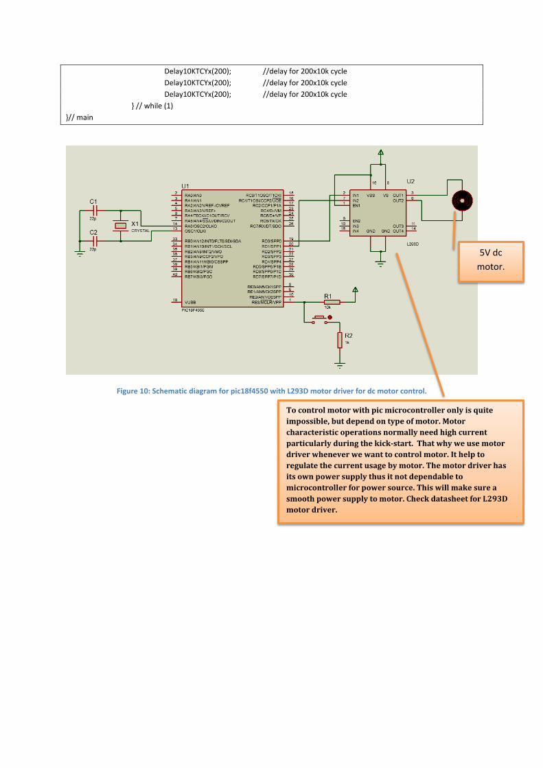
Figure 10: Schematic diagram for pic18f4550 with L293D motor driver for dc motor control.
To control motor with pic microcontroller only is quite impossible, but depend on type of motor. Motor characteristic operations normally need high current particularly during the kick-start. That why we use motor driver whenever we want to control motor. It help to regulate the current usage by motor. The motor driver has its own power supply thus it not dependable to microcontroller for power source. This will make sure a smooth power supply to motor. Check datasheet for L293D motor driver.
5V dc motor.

2.5 Keypad 2.5.1 PIC18F4550_keypad.c (main file) // This is a sample program written for SeST Board@PMJ // PIC18F4550 + keypad // used C language // MPLAB IDE v8.92 // MPLAB C18 V3.46 compiler // Last Updated date: 11 March 2015 // Embedded System Applications - Zero to Hero for Beginner #include <p18f4550.h> //include the PIC18F model of PIC header file #include "delay18.h" //include the delay functions #include "system.h" //include system header file #include "keypad.h" //include keypad functions header file #include "lcd.h" //include lcd functions header file //config word #pragma config FOSC = HS // Maximum Fosc is 48MHz, so if 20MHz external crystal is used, need to select HS #pragma config PWRT = ON // Power Up Timer Enable bit #pragma config BOR = OFF // Brown-out Reset Enable bits #pragma config WDT = OFF // Watch-Dog Timer Enable bit #pragma config PBADEN = ON // PORTB analog pin as analog input after Reset #pragma config MCLRE = ON // MCLR pin enable, RE3 input disabled #pragma config LVP = OFF // Low voltage programming disable //function prototype void test_keypad(void); rom const char string_poli[] = " Politeknik\n Mersing"; //main fucntion void main(void) { // ensure all the hardware port in zero initially PORTA = 0; PORTB = 0; PORTC = 0; PORTD = 0; PORTE = 0; // Initialize the I/O port direction. TRISA = 0b00010001; TRISB = 0b00001111; TRISC = 0b10010011; TRISD = 0; TRISE = 0; // Initialize the LCD. lcd_initialize(); // Display message lcd_clear_msg(string_poli); //display poli delay_ms(500); //wait for ~2s
Port direction to determine which is output or input. Set 1 for input or 0 for output.

while (1) { test_keypad(); } // while (1) }// main void test_keypad(void) { unsigned char i = 0; char c_pressed_key; static char sz_keys_array[] = "123A456B789C*0#D"; // Display message lcd_clear_msg("Test Keypad\nPlease press:"); // Loop to test every key in the keypad while (sz_keys_array[i] != '\0') { // Display message lcd_goto(0x4E); lcd_putchar(sz_keys_array[i]); // Waiting for user to press the keypad according to LCD message c_pressed_key = c_key_to_ASCII(c_wait_keypad()); delay_ms(50); // If incorrect key is pressed, trap the error. if (c_pressed_key != sz_keys_array[i]) { // Display the error messages and trap the error. lcd_error_trap("Error:\nIncorrect Key"); return; //terminate the test and return to main menu } // Increase the counter. i++; }//while (sz_keys_array[i] != '\0') delay_ms(200); }
2.5.2 Keypad.c //keypad.c #include <p18f4550.h> //include the PIC18F model of PIC header file #include "system.h" #include "delay18.h" #include "keypad.h" unsigned char c_read_keypad(void) { //start the scanning process KP_R1 = 0; // scan keypress on 1st row: 1, 2, 3, A KP_R2 = 1; KP_R3 = 1; KP_R4 = 1; //Delay a short time for the pin to get to correct state before detecting proper key
There are 2 common method to use the keypad with microcontroller. Using interrupt or scanning.
In this sample coding, we use scanning method. We turn off 1 row and set the other 3 row. And within the reset row, we wait for 10 micro seconds for pressed button on any button on row 1. If no pressed button, the scanning process continue.
This instruction is calling the test_keypad function to run/operate.
This is where we determine the keypad button layout. This must be the same as real keypad.
delay_10us(1); if (KP_C1 == 0) return 1; // Key '1' is pressed if (KP_C2 == 0) return 2; // Key '2' is pressed if (KP_C3 == 0) return 3; // Key '3' is pressed if (KP_C4 == 0) return 10; // Key 'A' is pressed, we will store as 10 KP_R1 = 1; // scan keypress on 2nd row: 4, 5, 6, B KP_R2 = 0; KP_R3 = 1; KP_R4 = 1; //Delay a short time for the pin to get to correct state before detecting proper key delay_10us(1); if (KP_C1 == 0) return 4; // Key '4' is pressed if (KP_C2 == 0) return 5; // Key '5' is pressed if (KP_C3 == 0) return 6; // Key '6' is pressed if (KP_C4 == 0) return 11; // Key 'B' is pressed, we will store as 11 KP_R1 = 1; // scan keypress on 3rd row: 7, 8, 9, C KP_R2 = 1; KP_R3 = 0; KP_R4 = 1; //Delay a short time for the pin to get to correct state before detecting proper key delay_10us(1); if (KP_C1 == 0) return 7; // Key '7' is pressed if (KP_C2 == 0) return 8; // Key '8' is pressed if (KP_C3 == 0) return 9; // Key '9' is pressed if (KP_C4 == 0) return 12; // Key 'C' is pressed, we will store as 12 KP_R1 = 1; // scan keypress on 4th row: *, 0, #, D KP_R2 = 1; KP_R3 = 1; KP_R4 = 0; //Delay a short time for the pin to get to correct state before detecting proper key delay_10us(1); if (KP_C1 == 0) return 14; // Key '*' is pressed, we will store as 14 if (KP_C2 == 0) return 0; // Key '0' is pressed if (KP_C3 == 0) return 15; // Key '#' is pressed, we will store as 15 if (KP_C4 == 0) return 13; // Key 'D' is pressed, we will store as 13 return 0xFF; // if no key press, the register is 0xFF } unsigned char c_key_to_ASCII (unsigned char key_number) { // if number is from 0 to 9, convert to ASCII character by adding 0x30 if (key_number < 10) return key_number + 0x30; // if number is greater than 9, it is alphabet and symbol if (key_number == 10) return 'A'; // convert to ASCII A if (key_number == 11) return 'B'; // convert to ASCII B if (key_number == 12) return 'C'; // convert to ASCII C if (key_number == 13) return 'D'; // convert to ASCII D if (key_number == 14) return '*'; // convert to ASCII * if (key_number == 15) return '#'; // convert to ASCII # return 0; //no key pressed, return null }
unsigned char c_wait_keypad(void) { // The pressed key. unsigned char c_pressed_key = 0xFF; // Wait until the key is pressed. do { c_pressed_key = c_read_keypad(); } while (c_pressed_key == 0xFF); // Wait until the key is released. while (c_read_keypad() != 0xFF); return c_pressed_key; }
2.5.3 Keypad.h #ifndef _KEYPAD_H #define _KEYPAD_H extern unsigned char c_read_keypad(void); extern unsigned char c_key_to_ASCII (unsigned char key_number); extern unsigned char c_wait_keypad(void); #endif
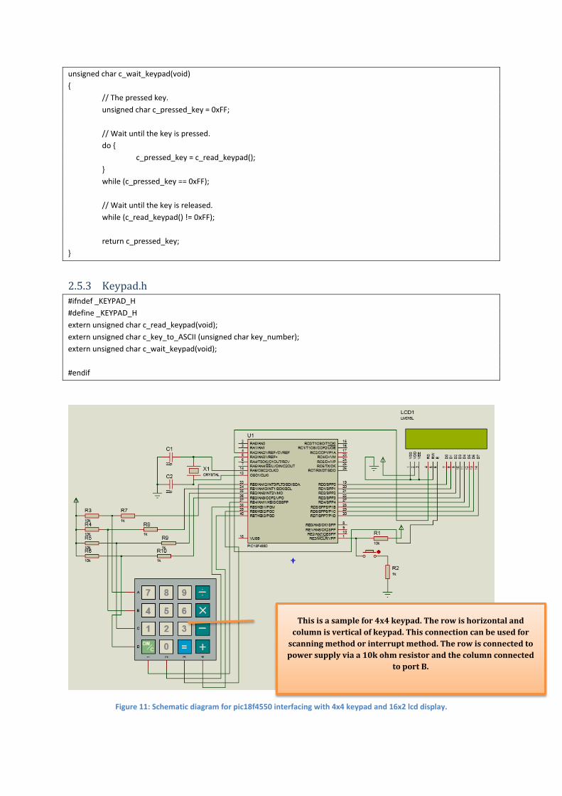
Figure 11: Schematic diagram for pic18f4550 interfacing with 4x4 keypad and 16x2 lcd display.
This is a sample for 4x4 keypad. The row is horizontal and column is vertical of keypad. This connection can be used for
scanning method or interrupt method. The row is connected to power supply via a 10k ohm resistor and the column connected
to port B.

Chapter 3 From the previous chapter, we can see a few of simple program which intended to make better understanding before we go for much complicated embedded system project. Therefore, below is a list for a few concepts in Part II of our guide book that we can use to enhance the level of complexity of the project.
3.1 Pulse Width Modulation The pulse width modulation (PWM) mode produces a PWM output at 10-bit resolution. A PWM output is basically a square waveform with a specified period and duty cycle.
Figure 12: The PWM waveform.
The PWM is quite useful if we intend to control motor. The sample program in chapter 2 only shows how to control rotation, but not the speed. If we need to control the speed rotation of the motor, we must apply the PWM element in the motor control instruction. Detail program will be in Part II of our guide book.
3.2 Interrupt An interrupt is an event that requires the CPU to stop normal program execution and then execute a program code related to the event causing the interrupt. Interrupts can be generated internally (by some event inside the chip) or externally (by some external event). An example of an internal interrupt is a timer overflowing or the A/D completing a conversion. An example of an external interrupt is an I/O pin changing state. Interrupts can be useful in many applications such as: 3.2.1 Time Critical Applications Applications which require the immediate attention of the CPU can use interrupts. For example, in an emergency such as a power failure or fire in a plant the CPU may have to shut down the system immediately in an orderly manner. In such applications an external interrupt can force the CPU to stop whatever it is doing and take immediate action.
3.2.2 Performing Routine Tasks Many applications require the CPU to perform routine work at precise times, such as checking the state of a peripheral device exactly every millisecond. A timer interrupt scheduled with the required timing can divert the CPU from normal program execution to accomplish the task at the precise time required. 3.2.3 Task Switching In Multi-Tasking Applications In multi-tasking applications, each task may have a finite time to execute its code. Interrupt mechanisms can be used to stop a task should it consume more than its allocated time. 3.2.4 To Service Peripheral Devices Quickly Some applications may need to know when a task, such as an A/D conversion, is completed. This can be accomplished by continuously checking the completion flag of the A/D converter. A more elegant solution would be to enable the A/D completion interrupt so the CPU is forced to read the converted data as soon as it becomes available. Interrupts in the PIC18F family can be divided into two groups: high priority and low priority. Applications that require more attention can be placed in the higher priority group. A high-priority interrupt can stop a low-priority interrupt that is in progress and gain access to the CPU. However, high-priority interrupts cannot be stopped by low-priority interrupts. If the application does not need to set priorities for interrupts, the user can choose to disable the priority scheme so all interrupts are at the same priority level. High-priority interrupts are vectored to address 00008H and low-priority ones to address 000018H of the program memory. Normally, a user program code (interrupt service routine, ISR) should be at the interrupt vector address to service the interrupting device. Interrupt also can be used to detect pressed button when interfacing with keypad. More detail explanation and program sample code will be in our Part II guide book.
3.3 USB Connection for Communication The PIC18F4550 microcontroller support for usb connection. To use the usb feature in pic microcontroller, the level of complexity is not for beginner, the protocol setting need to precisely configure to get valid data. In our Part II guide book, we will include a sample application of controlling an output port using a computer and pic microcontroller using usb connection.

References [1] M. A. Mazidi, R. D. McKinlay, and D. Causey, PIC Microcontroller and Embedded Systems:
Using Assembly and C for PIC18: Pearson Prentice Hall, 2008. [2] "The Microchip PIC," in Microcontroller Programming, ed: CRC Press, 2006, pp. 129-140.