emerge tm mpx hd multipoint extender - avstore
TRANSCRIPT

EmergeTM MPX
HD Multipoint Extender
Installer/User Guide

USA Notification
Warning: Changes or modifications to this unit not expressly approved by the party responsible for compliance
could void the user's authority to operate the equipment.
Note: This equipment has been tested and found to comply with the limits for a Class B digital device,
pursuant to Part 15 of the FCC Rules. These limits are designed to provide reasonable protection against
harmful interference when the equipment is operated in a commercial environment. This equipment generates,
uses and can radiate radio frequency energy and, if not installed and used in accordance with the instruction
manual, may cause harmful interference to radio communications. Operation of this equipment in a residential
area is likely to cause harmful interference in which case the user will be required to correct the interference at
his own expense. If this equipment does cause harmful interference to radio or television reception, which can
be determined by turning the equipment off and on, the user is encouraged to try to correct the interference by
one of the following measures: reorient or relocate the receiving antenna; increase the separation between the
equipment and receiver; connect the equipment into an outlet on a circuit different from that to which the
receiver is connected; consult the dealer or an experienced radio/TV technician for help. Only Avocent-
supplied antennas used in a configuration recommended by Avocent are supported by this product.
FCC Radiation Exposure Statement: This equipment complies with FCC radiation exposure limits set forth for
an uncontrolled environment. This equipment should be installed to provide a 20 cm separation from all
persons. This transmitter must not be co-located or operating in conjunction with any other antenna or
transmitter. Operations in the 5.15-5.25GHz band are restricted to indoor usage only.
Note: In order to maintain compliance with relevant emission standards, the MPX1000T extender analog
audio cables should contain a ferrite with a value of at least 150 ohms impedance at 100 MHz. A clamp on
ferrite may be used.
Canadian Notification
This digital apparatus does not exceed the Class B limits for radio noise emissions from digital apparatus set
out in the Radio Interference Regulations of the Canadian Department of Communications.
Note: In order to maintain compliance with relevant emission standards, the MPX1000T extender analog
audio cables should contain a ferrite with a value of at least 150 ohms impedance at 100 MHz. A clamp on
ferrite may be used.
Le présent appareil numérique n'émet pas de bruits radioélectriques dépassant les limites applicables aux
appareils numériques de la classe B prescrites dans le Règlement sur le brouillage radioélectrique édicté par le
Ministère des Communications du Canada.
De manière à maintenir la normes d'émission analogue, les câbles audio devraient contenir un ferrite avec une
valeur d'impédance d'au moins 150 ohms à 100 MHz. Une attache sur ferrite peut être utilisée.
Safety and EMC Approvals and Markings (Compliance Model Number (CMN): 2003 Series)
IEC 60950-1:2000, IEC 60065:2001+ Amd 1:2005 EN 60950-1:2001, EN 60065:2002 UL 60950 3rd Ed. /
CSA 22.2 No. 60950:2000, UL 60065:2002, EN 55103-1:1997, EN 55022:1998+A1:2000+A2:2003,EN
61000-3-2:1995 EN 61000-3-3:1995+A1:2001, EN 55103-2:1997, EN 55024:1998+A1:2001+A2:2003, FCC
Part 15 Subpart B Class B, FCC Part 15 Subpart C, FCC Part 15 Subpart E, EN 50392:2004, EN 301 893 v.
1.2.3 (2003-08), EN 489-1 v. 1.4.1 (2002-08), EN 489-17 V. 1.2.1 (2002-08)

Emerge™ MPX
HD Multipoint ExtenderInstaller/User Guide
Avocent, the Avocent logo and Emerge are trademarks or registered
trademarks of Avocent Corporation or its affiliates. HDMI, the HDMI
logo and High-Definition Multimedia Interface are trademarks or
registered trademarks of HDMI Licensing LLC. All other marks are the
property of their respective owners.
© 2008 Avocent Corporation. All rights reserved. 590-671-501F

Instructions
This symbol is intended to alert the user to the presence of important operating and maintenance
(servicing) instructions in the literature accompanying the appliance.
Dangerous Voltage
This symbol is intended to alert the user to the presence of uninsulated dangerous voltage within the
product’s enclosure that may be of sufficient magnitude to constitute a risk of electric shock to persons.
Power On
This symbol indicates the principal on/off switch is in the on position.
Power Off
This symbol indicates the principal on/off switch is in the off position.
Protective Grounding Terminal
This symbol indicates a terminal which must be connected to earth ground prior to making any other
connections to the equipment.

iii
Figure 1.1: Example MPX Multipoint Extender Configuration ........................................................ 3
Figure 2.1: Emerge MPX1000 HD Multipoint Extender Transmitter (Front)................................ 11
Figure 2.2: Emerge MPX1000 HD Multipoint Extender Transmitter (Rear) ................................. 12
Figure 2.3: Emerge MPX1000 HD Multipoint Extender Receiver (Front)..................................... 14
Figure 2.4: Emerge MPX1000 HD Multipoint Extender Receiver (Rear) ...................................... 15
Figure 2.5: Emerge MPX1000 HD Multipoint Extender Receiver (Front)..................................... 16
Figure 2.6: Emerge MPX1000 HD Multipoint Extender Receiver (Rear) ...................................... 17
Figure 2.7: HDMI Media Module ................................................................................................... 19
Figure 2.8: HD15 Media Module .................................................................................................... 20
Figure 3.1: Control LAN Settings.................................................................................................... 23
Figure 3.2: System Settings ............................................................................................................. 24
Figure 3.3: Bindings Page............................................................................................................... 27
Figure 3.4: Bound Receiver Status .................................................................................................. 34
Figure 3.5: Change Login Password Page ..................................................................................... 35
Figure 4.1: Transmitter Tuning Parameters - Basic Settings ......................................................... 39
Figure 4.2: Receiver Tuning Parameters ........................................................................................ 40
Figure 4.3: Transmitter Media LAN Settings .................................................................................. 43
Figure 4.4: Serial Passthrough Mode ............................................................................................ 45
Figure 4.5: Serial Settings Page: Serial Parameters ...................................................................... 46
Figure 4.6: IR Flow: Transmitter to Receiver ................................................................................. 47
Figure 4.7: IR Flow: Primary Receiver to Transmitter................................................................... 47
Figure 4.8: IR Loopback.................................................................................................................. 48
Figure 4.9: Serial Settings Page: IR Parameters ............................................................................ 49
Figure 4.10: System Reboot Page.................................................................................................... 52
Figure 4.11: Reset to Factory Defaults Page .................................................................................. 53
Figure C.1: MPX Receiver LED Status Indicators.......................................................................... 63
Figure C.2: MPX Receiver Rear LED Status Indicators................................................................. 66
Figure E.1: Display Device Settings Page for MPX1000 Receivers ............................................... 68
Figure E.2: Display Device Settings Page for MPX1500 Receivers ............................................... 69
Figure E.3: Transmitter Status Table .............................................................................................. 70
Figure E.4: Transmitter Media LAN Performance ......................................................................... 71
Figure F.1: Transmitter Rack Mount Brackets ............................................................................... 74
Figure F.2: Parts for Under Desk Mounting Option....................................................................... 75
LIST OF FIGURES

iv MPX Extender Installer/User Guide
Figure F.3: Installing the Horizontal Mounting Bracket (Under Desk Option) ............................. 75
Figure F.4: MPX1500 Mounting Bracket........................................................................................ 76
Figure F.5: MPX1500 Power Supply Bracket................................................................................. 77

v
Table 1.1: System Definitions for an MPX1000 Extender Solution .................................................. 3
Table 1.2: List of Accessories ............................................................................................................ 7
Table 2.1: Front Panel (Transmitter) .............................................................................................. 11
Table 2.2: Rear Panel (Transmitter) ............................................................................................... 12
Table 2.3: Front Panel ( Receiver) .................................................................................................. 14
Table 2.4: Rear Panel (Receiver) .................................................................................................... 15
Table 2.5: Front Panel ( Receiver) .................................................................................................. 16
Table 2.6: Rear Panel (Receiver) .................................................................................................... 17
Table 4.1: Transmitter Tuning Parameters - Basic Settings ........................................................... 38
Table 4.2: Receiver Tuning Parameters .......................................................................................... 40
Table 4.3: Methods for Fine Tuning ................................................................................................ 41
Table 4.4: Status Page Information ................................................................................................. 49
Table 4.5: Buttons for Manual Menu Navigation............................................................................ 53
Table 4.6: Buttons for Automatic Menu Display Mode ................................................................... 54
Table 4.7: Buttons for Parameter Modification Mode .................................................................... 55
Table C.1: LED Status - Wireless Connection ................................................................................ 64
Table C.2: LED Status - Wired Connection .................................................................................... 64
Table C.3: LED Status - Reset Button Press ................................................................................... 65
Table C.4: LED Status - Flash Update............................................................................................ 65
Table G.1: MPX1000T HD Multipoint Extender Product Specifications ....................................... 78
Table G.2: MPX1000R HD Multipoint Extender Product Specifications ....................................... 79
Table G.3: MPX1000T HDMI Input Module Product Specifications ............................................. 80
Table G.4: MPX1000R HDMI Output Module Product Specifications .......................................... 81
Table G.5: MPX1000T HD15 (VGA) Input Module Product Specifications .................................. 82
Table G.6: MPX1000R HD15 (VGA) Output Module Product Specifications................................ 83
Table G.7: MPX1500R HD Multipoint Extender Product Specifications ....................................... 83
Table H.1: Firmware and Hardware Versions Page Information .................................................. 87
Table J.1: MPX Extender Supported ISO Country Codes............................................................... 92
LIST OF TABLES

vi
Table K.1: MPX1000 Transmitter Kit Contents .............................................................................. 95
Table K.2: MPX1000 Receiver Kit Contents ................................................................................... 95
Table K.3: MPX1000 Receiver HDMI Media Module Kit Contents ............................................... 95
Table K.4: MPX1000 Transmitter HDMI Media Module Kit Contents .......................................... 95
Table K.5: MPX1000 Receiver VGA Media Module Kit Contents.................................................. 96
Table K.6: MPX1000 Transmitter VGA Media Module Kit Contents ............................................. 96
Table K.7: MPX1500 Receiver Kit Contents ................................................................................... 96
LIST OF TABLES

vii MPX Extender Installer/User Guide

ix
Chapter 1: Product Overview.......................................................................................... 1
Introduction ....................................................................................................................................... 1
Features ............................................................................................................................................. 1
Video ........................................................................................................................................... 1
Audio........................................................................................................................................... 2
Control........................................................................................................................................ 2
Benefits............................................................................................................................................... 2
System Overview ................................................................................................................................ 3
System definitions ....................................................................................................................... 3
Understanding User Interfaces.......................................................................................................... 6
Browser-based configuration ..................................................................................................... 6
Front panel display..................................................................................................................... 6
Accessories......................................................................................................................................... 7
Compatibility with Attached Devices................................................................................................. 8
EDID compatibility..................................................................................................................... 8
HDCP compatibility ................................................................................................................... 9
Rack Mount Safety Considerations.................................................................................................. 10
Chapter 2: Hardware Overview..................................................................................... 11
Transmitter....................................................................................................................................... 11
Receiver ........................................................................................................................................... 13
MPX1000R overview ................................................................................................................ 13
MPX1500R overview ................................................................................................................ 15
Media Modules ................................................................................................................................ 18
HDMI media module ................................................................................................................ 18
HD15 media module ................................................................................................................. 19
Cross conversion ...................................................................................................................... 20
Chapter 3: Installation ................................................................................................... 21
Getting Ready .................................................................................................................................. 21
Installing Media Modules ................................................................................................................ 21
Transmitter Configuration ............................................................................................................... 22
LAN settings.............................................................................................................................. 22
Validating media LAN connectivity .......................................................................................... 24
TABLE OF CONTENTS

x MPX Extender Installer/User Guide
Setting explicit receiver bindings (Optional)............................................................................ 25
Receiver Configuration.................................................................................................................... 27
Accessing your receiver’s web interface .................................................................................. 27
Configure receiver system settings (Optional) ......................................................................... 29
Multiple transmitter considerations ......................................................................................... 29
Configure receiver password (Optional).................................................................................. 30
Firmware Version Checking ............................................................................................................ 30
Initiating A Media Session ............................................................................................................... 30
Troubleshooting........................................................................................................................ 31
Transmitter and Receiver Placement............................................................................................... 32
Final Adjustments ............................................................................................................................ 34
Extension of IR and Serial Data ...................................................................................................... 34
Change Password ............................................................................................................................ 34
Chapter 4: Additional Functions................................................................................... 37
System Tuning .................................................................................................................................. 37
Transmitter tuning parameters ................................................................................................. 37
Receiver tuning parameters...................................................................................................... 39
Fine tuning suggestions ............................................................................................................ 41
Serial Control .................................................................................................................................. 43
I/R Control ....................................................................................................................................... 46
Configuring IR control ............................................................................................................. 48
Status Monitoring ............................................................................................................................ 49
Connection status ..................................................................................................................... 49
Media LAN performance .......................................................................................................... 51
System Reboot .................................................................................................................................. 52
Reset to Factory Defaults ................................................................................................................ 52
Front Panel Display......................................................................................................................... 53
Display modes........................................................................................................................... 53
Main menu ................................................................................................................................ 55
Screen saver.............................................................................................................................. 57
Appendix A: Technical Support ....................................................................................................... 59
Appendices.................................................................................................................... 59
Appendix B: Radio Considerations.................................................................................................. 60
Appendix C: MPX Receiver Status LEDs ........................................................................................ 63

xi
Appendix D: Audio........................................................................................................................... 67
Appendix E: Video Troubleshooting................................................................................................ 68
Appendix F: Mounting Options ....................................................................................................... 74
Appendix G: Technical Specifications ............................................................................................. 78
Appendix H: Displaying Firmware and Hardware Versions .......................................................... 87
Appendix I: Upgrading MPX Firmware .......................................................................................... 88
Appendix J: Supported ISO Country Codes .................................................................................... 92
Appendix K: Kit Contents ................................................................................................................ 95

xii MPX Extender Installer/User Guide

1
CHAPTER
1Product Overview
Introduction
Emerge™ MPX multipoint transmitters and receivers work in unison to form a managed audio
video extension network able to deliver a synchronized stream of high definition computer graphics
or video and associated audio from one source to as many as eight display devices in a wired or
wireless manner. Device identification, device control and content protection information, in the
form of IR and serial data, are passed from source to sink through the extension network, providing
a fully managed solution.
Features
The Emerge MPX1000T transmitter is a modular product. Audio/Video (A/V) data, whether
analog or digital, is converted to an encoded, compressed and encrypted digital stream before
transmission. To ensure support for a wide range of current and future video standards, video input
and output connections are provided in the form of field-installable media modules. Modular
support is available for HDMI video and audio, DVI-D and analog signals, including component
video, computer graphics and stereo audio.These media modules are purchased separately.
The Emerge MPX1000R receiver is a modular product similar to the MPX1000T transmitter.
Modular support is available for HDMI video and audio, DVI-D and analog signals, including
computer graphics and stereo audio.These media modules are purchased separately.
The Emerge MPX15000R features a single DVI-I video connector, which offers support for
HDMI, DVI-D, DVI-A, VGA, composite, component and s-video display devices. The product
also features connectors for external analog audio and coaxial and optical S/PDIF digital audio.
Video
MPX extenders support both progressive and interlaced video formats, however, they do not cross-
convert from one to the other. MPX transmitters support a wide range of source device video
formats, including: HDMI, DVI-D, VGA and component video.
The MPX1000R receiver supports the following display device video formats: HDMI, DVI-D and
VGA display devices.

2 MPX Extender Installer/User Guide
The MPX1500R receiver supports a wide range of display device video formats, including: HDMI,
DVI-D, DVI-A, VGA, composite, component and s-video display devices.
Audio
All MPX extenders support embedded HDMI digital audio and external analog audio via female
RCA jacks. In addition, the MPX1500R features connectors for optical and coaxial S/PDIF digital
audio. See Audio on page 67 for additional information.
Control
The products allow both RS232 and infrared control of source and display devices. Every MPX
extender has both IR receiver and emitter capability. IR strings are passed across the wired or
wireless media LAN, making it possible to control source devices while standing at a display
device, and vice-versa. A loopback function also makes it possible to control devices locally from
either side of the extension network. Likewise, bi-directional transmission of RS232 signals allows
device management across the extension network.
Benefits
The Emerge MPX1000 HD multipoint extender provides the following benefits:
• Multipoint wired or wireless extension of high definition content
• Low latency from input at transmitter to output at receiver, making the product suitable for live
presentations or recorded media
• Ability to send HDMI audio or unbalanced analog audio
• Ability to extend A/V control signals, including serial and IR
• Synchronized media across multiple display devices
• Lip sync is maintained at each receiver
• Simple web-based configuration is provided at the transmitter
• Provides content security through HDCP digital rights management
• Passes EDID information for plug-and-play operation
• Passes CEC information for native control of HDMI devices
• Product is field upgradable to support future functionality

Chapter 1: Product Overview 3
System Overview
The following diagram illustrates a typical configuration, including a single transmitter and three
receiver units using HDMI source and display devices.
Figure 1.1: Example MPX Multipoint Extender Configuration
System definitions
The Emerge MPX1000 HD multipoint extender system consists of one transmitter and one to eight
receiver units. The following terms are used in this manual to identify common components of an
MPX1000 extender solution:
Table 1.1: System Definitions for an MPX1000 Extender Solution
Term Definition
Active EDID A merged EDID string that describes the subset of characteristics supported by the
primary display device and the MPX1000 transmitter
Bound Receiver A receiver that is actively connected to a transmitter over a wired or wireless link
Control LAN A LAN connection to an MPX receiver or transmitter that allows access to its on-
board web interface. On MPX1000 extenders, this port is labelled L1. On an
MPX1500 receiver, the LAN port provides the combined functions of media LAN
and control LAN.
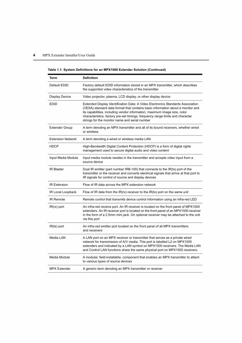
4 MPX Extender Installer/User Guide
Default EDID Factory default EDID information stored in an MPX transmitter, which describes
the supported video characteristics of the transmitter
Display Device Video projector, plasma, LCD display, or other display device
EDID Extended Display Identification Data: A Video Electronics Standards Association
(VESA) standard data format that contains basic information about a monitor and
its capabilities, including vendor information, maximum image size, color
characteristics, factory pre-set timings, frequency range limits and character
strings for the monitor name and serial number
Extender Group A term denoting an MPX transmitter and all of its bound receivers, whether wired
or wireless
Extension Network A term denoting a wired or wireless media LAN
HDCP High-Bandwidth Digital Content Protection (HDCP) is a form of digital rights
management used to secure digital audio and video content
Input Media Module Input media module resides in the transmitter and accepts video input from a
source device
IR Blaster Dual IR emitter (part number IRB-100) that connects to the IR(tx) port of the
transmitter or the receiver and converts electrical signals that arrive at that port to
IR signals for control of source and display devices
IR Extension Flow of IR data across the MPX extension network
IR Local Loopback Flow of IR data from the IR(rx) receiver to the IR(tx) port on the same unit
IR Remote Remote control that transmits device control information using an infra-red LED
IR(rx) port An infra-red receive port. An IR receiver is located on the front panel of MPX1000
extenders. An IR receiver port is located on the front panel of an MPX1500 receiver
in the form of a 2.5mm mini jack. On optional receiver may be attached to the unit
via this port
IR(tx) port An infra-red emitter port located on the front panel of all MPX transmitters
and receivers
Media LAN A LAN port on an MPX receiver or transmitter that serves as a private wired
network for transmission of A/V media. This port is labelled L2 on MPX1000
extenders and indicated by a LAN symbol on MPX1500 receivers. The Media LAN
and Control LAN functions share the same physical port on MPX1500 receivers.
Media Module A modular, field-installable, component that enables an MPX transmitter to attach
to various types of source devices
MPX Extender A generic term denoting an MPX transmitter or receiver
Table 1.1: System Definitions for an MPX1000 Extender Solution (Continued)
Term Definition

Chapter 1: Product Overview 5
Output Media Module Output media module that resides in MPX1000 receivers and outputs video data to
a display device
Primary Display
Device
A display device attached to the primary MPX receiver
Primary EDID EDID information received from the primary display device, which describes the
characteristics of the display device
Primary Receiver A single MPX receiver that you specify as the primary unit during configuration for
each system.
The primary receiver has the following characteristics:
• Only the primary receiver reports EDID information back to the transmitter, and
thus, back to the source device
• The primary receiver is the only receiver capable of bi-directional IR transfers
with the MPX transmitter
• The primary receiver is the selected unit for bi-directional RS232 serial transfers
with the transmitter
Receiver An MPX extender that inputs media from a transmitter, decrypts, uncompresses,
converts and manipulates the data back into the desired format and outputs to the
connected supported display devices
Source Device Computer, HD-DVD, or other source of A/V content
Transmitter An MPX extender that inputs media from a source device, compresses, encrypts
and transmits the content to an MPX receiver. MPX transmitters also provide a
back channel for transmission of control data back to a source device.
Transmitter Number An attr bute of a transmitter that enables multiple Extender Groups to co-exist on
the same wired media LAN
Universal A/V Port A DVI-I output port on an MPX1500 receiver that supports a wide range of video
formats such as: HDMI, DVI-D, DVI-A, VGA, component, composite and s-video.
Wired Link A 10/100 Mbps wired connection between a transmitter and bound receivers
Wireless Link An 802.11a connection between an MPX transmitter and bound receivers
Table 1.1: System Definitions for an MPX1000 Extender Solution (Continued)
Term Definition
6 MPX Extender Installer/User Guide
Understanding User Interfaces
Emerge MPX multipoint extenders are accessible through two primary user interfaces: an on-board
web server that allows browser-based configuration and system-wide monitoring and a front panel
display that provides push-button access to system status and initial network configuration.
Browser-based configuration
Browser-based configuration is available for both MPX transmitters and receivers. The web
interface provides access to the following functions:
• Configure system settings
• Configure network settings
• Display hardware and firmware version
• Display connection status and signal strength
• Update firmware
• Reboot system
• Reset to factory defaults
• Change password
Front panel display
The front panel of the transmitter has a 5-button menu display that provides access to the
following functions:
• View receiver connection status, including signal strength, data rate and frame rate. Single
receiver and multi-receiver scan modes are supported.
• View receiver configuration, including receiver name and MAC address. Single receiver and
multi-receiver scan modes are supported.
• View transmitter configuration, including IP (L1) and MAC address.
• Configure transmitter IP settings (L1).

Chapter 1: Product Overview 7
Accessories
The following accessories are available for use with Emerge MPX multipoint extenders.
Table 1.2: List of Accessories
Part Number Description
DB9-DUAL Dual DB9 female serial adapter
DMK-04 Wall/Desk mount bracket for MPX1500 extenders
DVI-HDMI Adapter (male) DVI-D to HDMI (female)
DVI-BNC3 Adapter for component video
DVI-HDMI/CEC Adapter (male) DVI-D to HDMI (female) with CEC support
DVI-YCV Adapter for composite and s-video
IRB-100 Dual IR emitter 3.5MM plug
IRB-Y 3.5mm mini jack splitter for connection of 2 IRB-100 emitters to an
MPX1000 extender
MPX1000MR-HD15 MPX1000R media module - VGA
MPX1000MR-HDMI MPX1000R media module - HDMI
MPX1000MT-HD15 MPX1000T media module - VGA
MPX1000MT-HDMI MPX1000T media module - HDMI
HD15-BNC3 HD15 to BNC3 female adapter for component video
HGA51G-DIR30 High gain 51GHz directional antenna with 30-degree beam width
PBK-01 Power supply bracket kit for MPX1500 extenders
RMK-56 Under desk mount brackets for MPX1000R
5G-1M 5GHz antenna extension kit: two 1-meter cables and brackets
5G-2M 5GHz antenna extension kit: two 2-meter cables and brackets
5G-3M 5GHz antenna extension kit: two 3-meter cables and brackets

8 MPX Extender Installer/User Guide
Compatibility with Attached Devices
The following sections provide guidelines regarding compatibility with source and display devices.
For an up to date device compatibility list, refer to the MPX extender product page on the Avocent
web site.
EDID compatibility
Display devices communicate with source devices using Extended Display Identification Data
(EDID), a Video Electronics Standards Association (VESA) standard data format that contains
basic information about a monitor and its capabilities, including vendor information, maximum
image size, color characteristics, factory pre-set timings, frequency range limits and character
strings for the monitor name and serial number.
EDID information stored in a display device is passed to the MPX receiver across the video cable
through a digital path called the Display Data Channel (DDC). The receiver forwards this
information to the transmitter across the media LAN. The transmitter, in turn, passes the EDID
information to the source device, thus allowing plug-and-play functionality among display and
source devices.
An MPX extender group has a single primary receiver, which has special responsibilities regarding
serial, IR, and video functionality. Regarding video, only the primary receiver passes its EDID
information back to the transmitter. Thus, the display device attached to the primary receiver
should be representative of the devices attached to other receivers.
The MPX transmitter is pre-configured with default EDID information, which indicates support
only for 640x480 resolution at 60Hz. This EDID will be passed to a source device in lieu of
information received from MPX receivers. As the transmitter learns about the attached display
devices through receiver bindings, it uses the information to create a more meaningful EDID string,
referred to as the active EDID string. The process occurs as follows:
• Initially, the active EDID string is blank
• When a receiver binding occurs, if the receiver is not the primary and if the active EDID string
is blank, then the transmitter will merge the received and default EDID strings such that the
resulting string represents the common features supported by both devices. This new string
will be stored as the active EDID and will be reported to the source device.
• When the primary receiver binds with the transmitter for the first time, the merge process will
be repeated using the default and primary EDID strings.
• When bindings are established with subsequent receivers, no action is taken.
• If a different receiver is selected as the primary via the transmitter’s web interface, then the
merge process will be repeated when a new primary EDID string is received.
• If the primary display device is replaced with a different model, then the receiver will report
the information to the transmitter and a merge process will take place.
NOTE: A blank screen may occur as EDID changes are being processed.

Chapter 1: Product Overview 9
HDCP compatibility
High-Bandwidth Digital Content Protection (HDCP) protects video content as it travels across
DVI-D or HDMI connections. Compliant devices do not allow users to make copies of protected
content and must effectively frustrate non-compliant attempts to view protected content.
For example, protected digital video content must be restricted to DVD quality when viewed on
non-HDCP display devices. Likewise, digital audio content is restricted to DAT quality on non-
HDCP digital audio output devices.
The following procedures ensure security for protected high definition content:
• Authentication: To identify non-compliant display devices
• Encryption: To prevent eavesdropping of protected content
• Key revocation: To block devices manufactured by vendors in violation of license agreements
from receiving HD content
MPX extenders serve as a repeater between compliant HDCP source and display devices. When all
display devices and the source device are HDCP compliant, high definition content will display
normally. HDCP special cases are handled as follows:
• When a new display device is added to the extension network, its key will be passed to the
source device for validation. The MPX transmitter will stop transmission of protected content
until the new display device is validated by the source device. The duration of this process may
last up to 15 seconds. The session will continue automatically upon successful authentication.
• In the event that a revoked key is detected, the session will terminate to all display devices. In
this case, the user will need to determine which display device is presenting a revoked key and
remove it from the extension network. Once removed, the MPX transmitter must be rebooted
to flush the key from its memory. At that point, the session should resume normally to all
compliant display devices.
• In the event that a display does not support HDCP, then the MPX receiver will not send
protected content to that display device. Unprotected analog audio will be processed normally
by the MPX receiver.
• The MPX receiver supports connection to compliant display devices. Connection to devices
such as an HDCP compliant switch, which may present multiple keys, is not supported. Should
this occur, the MPX receiver will refrain from sending video content to the device. Other
receivers in the extension network will not be affected.
10 MPX Extender Installer/User Guide
Rack Mount Safety Considerations
Before installing the appliance and other components in the rack (if not already installed), stabilize
the rack in a permanent location. Install the equipment starting at the bottom of the rack, then work
to the top. Avoid uneven loading or overloading of racks.
• Elevated ambient temperature: In a closed rack assembly, the operation temperature of the rack
environment can be greater than room ambient. Use care not to exceed the rated maximum
ambient temperature of the unit.
• Reduced air flow: Carefully install the equipment in a rack so that an adequate amount of
airflow is maintained for safe operation of the equipment.
• Mechanical loading: Avoid a potentially hazardous condition caused by uneven mechanical
loading by carefully mounting the equipment in the rack.
• Circuit overloading: Consider the connection of the equipment to the supply circuit and the
effect that overloading of circuits might have on overcurrent protection and supply wiring.
Observe equipment nameplate ratings for maximum current.
• Reliable earthing: Maintain reliable earthing of rack-mounted equipment. Pay particular
attention to supply connections other than direct connections to the branch circuit (for
example, use of power strips).

11
CHAPTER
2Hardware Overview
Transmitter
The transmitter encodes, compresses and sends media signals from a source device to a group of
bound receivers. Because the transmitter’s media input port is provided as a field-installable
module, it is able to support an expanding range of media types as additional modules are released.
Table 2.1 provides an overview of the transmitter.
IR Blaster
Front Panel Display
USBFront Panel Buttons
Reset
Omni-directional Antenna
Power
IR Receiver
Figure 2.1: Emerge MPX1000 HD Multipoint Extender Transmitter (Front)
Table 2.1: Front Panel (Transmitter)
Item Description
Front Panel Buttons Up, Down, Left and Right Arrows surrounding a Select button
used to view status and configuration settings and to establish
initial parameters
Unit Reset Recessed momentary button
12 MPX Extender Installer/User Guide
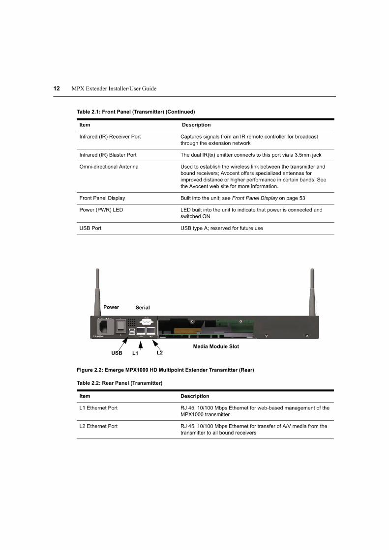
Figure 2.2: Emerge MPX1000 HD Multipoint Extender Transmitter (Rear)
Infrared (IR) Receiver Port Captures signals from an IR remote controller for broadcast
through the extension network
Infrared (IR) Blaster Port The dual IR(tx) emitter connects to this port via a 3.5mm jack
Omni-directional Antenna Used to establish the wireless link between the transmitter and
bound receivers; Avocent offers specialized antennas for
improved distance or higher performance in certain bands. See
the Avocent web site for more information.
Front Panel Display Built into the unit; see Front Panel Display on page 53
Power (PWR) LED LED built into the unit to indicate that power is connected and
switched ON
USB Port USB type A; reserved for future use
USB L1
Power Serial
Media Module Slot
L2
Table 2.2: Rear Panel (Transmitter)
Item Description
L1 Ethernet Port RJ 45, 10/100 Mbps Ethernet for web-based management of the
MPX1000 transmitter
L2 Ethernet Port RJ 45, 10/100 Mbps Ethernet for transfer of A/V media from the
transmitter to all bound receivers
Table 2.1: Front Panel (Transmitter) (Continued)
Item Description

Chapter 2: Hardware Overview 13
Receiver
The receiver decrypts, uncompresses and converts media signals back into the desired format and
outputs the signals to the connected display device. MPX1000 receivers feature a media module,
similar to the MPX1000 transmitter. MPX1500 receivers feature a universal A/V port. The
following sections provide an overview of these products.
MPX1000R overview
MPX1000 receiver is a modular product that provides support for HDMI, DVI-D and VGA display
devices. The following diagram illustrates the product.
Serial Port RS-232, 9-pin serial port to support serial passthrough for control
of display devices
Power IEC power socket with built-in fuse and on/off switch
USB Port USB Type B; reserved for future use
Media Module Slot Open slot on rear; used for insertion of A/V media module
Table 2.2: Rear Panel (Transmitter) (Continued)
Item Description

Power
Reset
USB
IR Blaster
StatusOmni-directional Antenna
IR Receiver
14 MPX Extender Installer/User Guide
Figure 2.3: Emerge MPX1000 HD Multipoint Extender Receiver (Front)
Table 2.3: Front Panel ( Receiver)
Item Description
Unit Reset Recessed momentary button
Infrared (IR) Receiver Captures signals from an IR remote controller for broadcast
through the extension network
Infrared (IR) Blaster The dual IR(tx) emitter connects via the 3.5mm jack
Omni-directional Antenna Used to establish the wireless link between the transmitter and
bound receivers. Avocent offers specialized antennas for
improved distance or higher performance in certain bands. See
the Avocent web site for more information
Status Lights Five colored LEDs that communicate the current state of the
device. Located on the front panel in the following order (left to
right): RED AMBER1 AMBER2 GREEN1 GREEN2
See MPX Receiver Status LEDs on page 63 for a detailed
description of LED status indicators
USB Port USB type A; reserved for future use
Power (PWR) Indicates that power is connected and turned ON
Power
USB Media Module SlotL1
Serial
L2
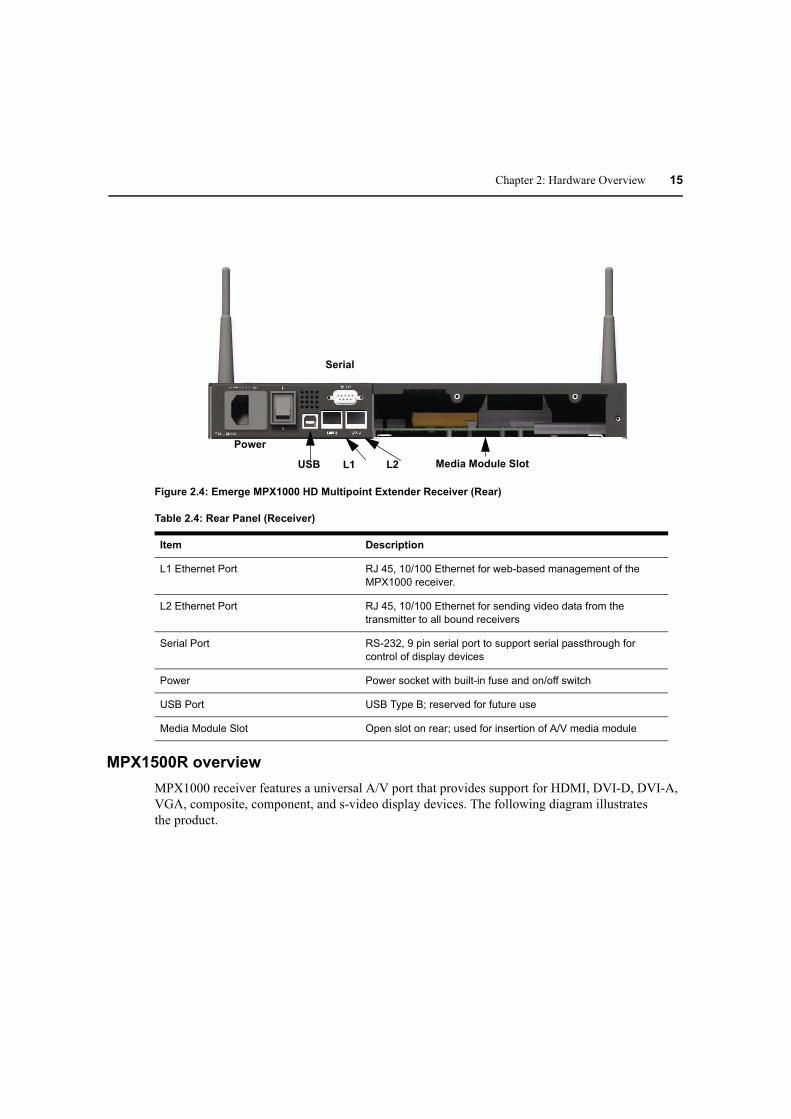
Chapter 2: Hardware Overview 15
Figure 2.4: Emerge MPX1000 HD Multipoint Extender Receiver (Rear)
Table 2.4: Rear Panel (Receiver)
Item Description
L1 Ethernet Port RJ 45, 10/100 Ethernet for web-based management of the
MPX1000 receiver.
L2 Ethernet Port RJ 45, 10/100 Ethernet for sending video data from the
transmitter to all bound receivers
Serial Port RS-232, 9 pin serial port to support serial passthrough for
control of display devices
Power Power socket with built-in fuse and on/off switch
USB Port USB Type B; reserved for future use
Media Module Slot Open slot on rear; used for insertion of A/V media module
MPX1500R overview
MPX1000 receiver features a universal A/V port that provides support for HDMI, DVI-D, DVI-A,
VGA, composite, component, and s-video display devices. The following diagram illustrates
the product.
Omni-directionalAntenna
Reset Status USB IR(Tx) IR(Rx)
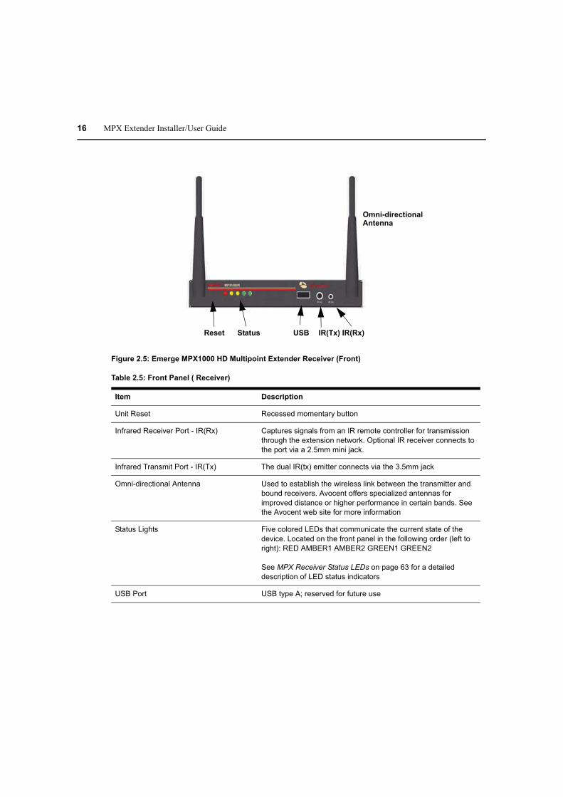
16 MPX Extender Installer/User Guide
Figure 2.5: Emerge MPX1000 HD Multipoint Extender Receiver (Front)
Table 2.5: Front Panel ( Receiver)
Item Description
Unit Reset Recessed momentary button
Infrared Receiver Port - IR(Rx) Captures signals from an IR remote controller for transmission
through the extension network. Optional IR receiver connects to
the port via a 2.5mm mini jack.
Infrared Transmit Port - IR(Tx) The dual IR(tx) emitter connects via the 3.5mm jack
Omni-directional Antenna Used to establish the wireless link between the transmitter and
bound receivers. Avocent offers specialized antennas for
improved distance or higher performance in certain bands. See
the Avocent web site for more information
Status Lights Five colored LEDs that communicate the current state of the
device. Located on the front panel in the following order (left to
right): RED AMBER1 AMBER2 GREEN1 GREEN2
See MPX Receiver Status LEDs on page 63 for a detailed
description of LED status indicators
USB Port USB type A; reserved for future use

Power
Status Dual Serial LAN Universal
A/V Port
RCA Toslink
Audio Audio
Chapter 2: Hardware Overview 17
Figure 2.6: Emerge MPX1000 HD Multipoint Extender Receiver (Rear)
Table 2.6: Rear Panel (Receiver)
Item Description
Power DC power input port
Rear Status LEDs Offers a subset of front panel status LED information. Rear
status LEDs are useful when front panel status LEDs are not
visible due to orientation of a deployed receiver.
Dual Serial Port RJ45 connector for attachment of optional DB9-DUAL adapter,
which splits into RS-232 DB9 female connectors. Supports
serial passthrough for control of display devices.
Ethernet LAN Port RJ 45, 10/100 Ethernet that provides combined media and
control LAN functionality
Universal A/V Port A DVI-I connector that provides connectivity to a wide range of
display devices, including: HDMI, DVI-D, DVI-A, VGA,
component, composite and s-video
RCA Audio Provides support for unbalanced analog stereo (left and right)
audio. Depending upon your firmware revision, the right channel
offers support for S/PDIF coaxial digital audio.

18 MPX Extender Installer/User Guide
Media Modules
Two types of media modules exist, as follows:
• Input media modules for MPX1000 transmitters
• Output media modules for MPX1000 receivers (shown below)
Media received from a source device at the input module of the transmitter is processed and passed
to bound receivers where it is properly converted and sent to display devices through the output
media module. Media modules must be installed in all MPX1000 extenders for proper operation.
NOTE: With your MPX1000 unit you have received two snap-on ferrites. If you are using the analog audio (RCA
Jacks) these ferrites should be applied to each end of the cables. Apply the ferrites approximately one inch from
the cable ends. One ferrite goes around both cables.
HDMI media module
The HDMI media module supports both HDMI and DVI-D signalling. HDMI functionality
includes support for HDMI video, embedded audio, EDID passing, digital rights management
(HDCP) and device control (CEC). DVI-D functionality includes video, external audio, EDID
passing and HDCP. DVI-D connectivity requires an DVI-HDMI adapter, which is included with
the media module.
Audio is limited to a single stream. HDMI embedded digital audio, if present, takes priority over
analog audio. See Audio on page 67 for additional information.
Toslink Audio Toslink connector that, depending upon your firmware revision,
provides support for optical S/PDIF digital audio
Table 2.6: Rear Panel (Receiver) (Continued)
Item Description
RCA Jacks (Unbalanced Audio)
HDMI Type A
Captive Screw
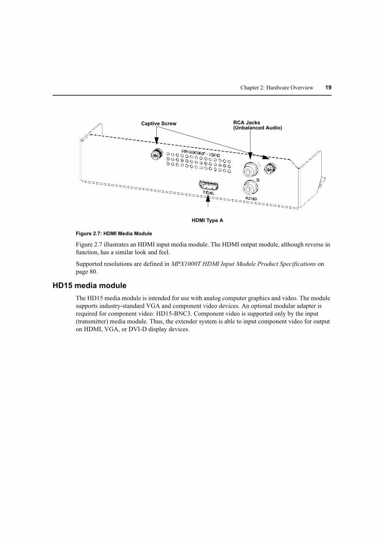
Chapter 2: Hardware Overview 19
Figure 2.7: HDMI Media Module
Figure 2.7 illustrates an HDMI input media module. The HDMI output module, although reverse in
function, has a similar look and feel.
Supported resolutions are defined in MPX1000T HDMI Input Module Product Specifications on
page 80.
HD15 media module
The HD15 media module is intended for use with analog computer graphics and video. The module
supports industry-standard VGA and component video devices. An optional modular adapter is
required for component video: HD15-BNC3. Component video is supported only by the input
(transmitter) media module. Thus, the extender system is able to input component video for output
on HDMI, VGA, or DVI-D display devices.
15-Pin HD female Connector
RCA Jacks (Unbalanced Audio)
Captive Screw
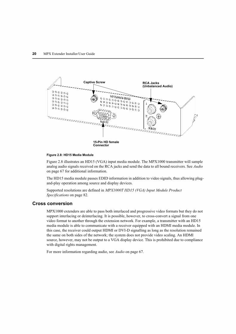
20 MPX Extender Installer/User Guide
Figure 2.8: HD15 Media Module
Figure 2.8 illustrates an HD15 (VGA) input media module. The MPX1000 transmitter will sample
analog audio signals received on the RCA jacks and send the data to all bound receivers. See Audio
on page 67 for additional information.
The HD15 media module passes EDID information in addition to video signals, thus allowing plug-
and-play operation among source and display devices.
Supported resolutions are defined in MPX1000T HD15 (VGA) Input Module Product
Specifications on page 82.
Cross conversion
MPX1000 extenders are able to pass both interlaced and progressive video formats but they do not
support interlacing or deinterlacing. It is possible, however, to cross-convert a signal from one
video format to another through the extension network. For example, a transmitter with an HD15
media module is able to communicate with a receiver equipped with an HDMI media module. In
this case, the receiver could output HDMI or DVI-D signalling as long as the resolution remained
the same on both sides of the network; the system does not provide video scaling. An HDMI
source, however, may not be output to a VGA display device. This is prohibited due to compliance
with digital rights management.
For more information regarding audio, see Audio on page 67.

21
CHAPTER
3Installation
Getting Ready
To begin installing your Emerge MPX extenders, do the following:
• Take proper precautions against antistatic discharge.
• Remove your MPX transmitter, receivers, antennas and media modules from their boxes.
• Refer to the kit contents list to ensure that you have all the items necessary for
your installation. See Kit Contents on page 95 for a complete list of product contents.
• Place the units on a stable working surface. To prevent radio receivers from being over-driven,
allow a distance of three feet between adjacent units.
• Connect antennas to the extenders. Fold the antennas inward while the extenders are in close
proximity to each other. Excessive signal strength may cause data loss and retransmission.
• Ensure that all units are turned off at this time.
Installing Media Modules
MPX1000MT media modules provide media input ports and are intended for use with MPX1000
transmitters. MPX1000MR media modules provide media output ports and are intended for use
with MPX1000 receivers.
NOTE: Proper electrostatic discharge (ESD) protection should be used at all times.
To install a module into your transmitter or receiver:
1. Align the edges of the media module with the open media module slot on the rear of the unit.
2. Slide the media module into the transmitter or receiver(s), until it is fully seated.
3. Fasten the media module into the unit using the provided screws. Do not over tighten or the
screw may be damaged.
22 MPX Extender Installer/User Guide
Transmitter Configuration
The transmitter can be configured by using an intuitive web interface. The following steps guide
you through this process.
LAN settings
To configure transmitter control LAN (L1) settings:
1. Attach the AC line cord and turn on your transmitter. The green LED should illuminate to
indicate presence of power. Use only an Avocent power cord.
2. Wait for the Avocent logo to appear on the front panel display indicating that the initial power-
up sequence is complete.
3. Using an Ethernet crossover cable or hub, connect a browser client to the control LAN port
(labeled L1) on the rear of the transmitter.
4. The default IP address for L1 of the transmitter is 192.168.1.1 with a subnet mask of
255.255.255.0. This may be changed using either the 5-button front-panel display or the web
interface. Refer to Configure control LAN on page 56 for detailed instructions regarding the
front-panel display.
5. Change the IP address of the browser client computer so it can directly access the transmitter,
for example 192.168.1.20, if necessary.
6. Launch a browser session to the IP address of the transmitter to invoke its web
configuration utility via L1, the control LAN port.
7. Type the default password, which is Admin (case sensitive).
8. If the unit has not yet been configured, you will be prompted to enter a country code. This code
is used by the product to establish allowable settings for wireless bands, channels and
power limits.
9. If desired, select the password page to change the system password. See Change Password on
page 34.
10. If you have not done so via the front panel, you may configure the IP address of the L1 control
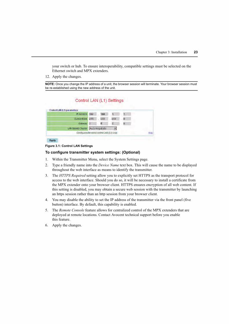
LAN port using the web interface. Figure 3.1 illustrates the network settings dialog box. To
alter the settings, select the Control LAN Settings page and set the parameters as follows:
a. Type the IP address for L1 (control LAN) to match the network on which it will be placed.
Use this address for subsequent browser connections. Do not use the following reserved IP
addresses: 0.0.0.0, 192.168.1.10, 192.168.1.1, 192.168.1.2, 192.168.10.xxx
or 192.168.11.xxx.
b. Type the subnet mask for L1.
c. Type the gateway address for L1, or 0.0.0.0 if there is no gateway.
11. The LAN Speed / Duplex setting allows you manually select 10 or 100Mbps LAN speed and
full or half duplex operation. By default, these settings will be automatically negotiated with
Chapter 3: Installation 23
your switch or hub. To ensure interoperability, compatible settings must be selected on the
Ethernet switch and MPX extenders.
12. Apply the changes.
NOTE: Once you change the IP address of a unit, the browser session will terminate. Your browser session must
be re-established using the new address of the unit.
Figure 3.1: Control LAN Settings
To configure transmitter system settings: (Optional)
1. Within the Transmitter Menu, select the System Settings page.
2. Type a friendly name into the Device Name text box. This will cause the name to be displayed
throughout the web interface as means to identify the transmitter.
3. The HTTPS Required setting allow you to explicitly set HTTPS as the transport protocol for
access to the web interface. Should you do so, it will be necessary to install a certificate from
the MPX extender onto your browser client. HTTPS ensures encryption of all web content. If
this setting is disabled, you may obtain a secure web session with the transmitter by launching
an https session rather than an http session from your browser client.
4. You may disable the ability to set the IP address of the transmitter via the front panel (five
button) interface. By default, this capability is enabled.
5. The Remote Console feature allows for centralized control of the MPX extenders that are
deployed at remote locations. Contact Avocent technical support before you enable
this feature.
6. Apply the changes.

24 MPX Extender Installer/User Guide
Figure 3.2: System Settings
Validating media LAN connectivity
Media session data (audio, video, and control information) is transferred from an MPX transmitter
to bound receivers either through the wireless LAN interface or the L2 wired LAN interface. By
default, MPX transmitters are configured for wireless operation. MPX receivers are configured
neither for wired or wireless operation, rather they search for an active transmitter first on their
wired and then on their wireless media LAN interfaces. The following sections will guide you
through a quick test of the wireless and wired modes of operation.
Wired Media LAN (L2) setup (Optional)
Perform the following steps if you wish to use MPX extenders in a wired mode of operation.
To set up a wired media LAN:
1. Interconnect the media LAN ports of the MPX transmitter and all receivers using standard
100Mbps Ethernet hubs or switches and UTP cabling.
NOTE: Wired connection should be made to the L2 of MPX1000 transmitters to the L2 port of MPX1000
receivers and to the LAN port, as indicated by the LAN symbol, on MPX1500 receivers.
2. Using your browser client, navigate to the Media LAN Settings page on the MPX transmitter.
This web page is illustrated in Figure 4.3 on page 43.
3. Select the radio button that enables wired operation.
NOTE: The IP address of MPX receiver’s media LAN port is dynamically assigned by its transmitter at bind time.
This process is similar to DHCP.
4. Although it is not possible to explicitly configure the IP address of the media LAN port of
MPX1000 receivers or transmitters, it is possible for 4 MPX1000 transmitters and bound

Chapter 3: Installation 25
receivers to share a single wired extension network. Skip to the next step if you are not
planning to install multiple transmitters on the same wired media LAN.
You may place more than one transmitter on a wired media LAN. To do so, select a unique
Transmitter Number from the pull-down menu on the media LAN Settings web page.
NOTE: To allow multiple groupings of transmitters and receivers to coexist on a shared wired media LAN, each
transmitter and its group of receivers must have a unique set of IP addresses.The Transmitter Number setting is
used to select a unique base address for a transmitter and its associated receivers.
NOTE: Media LAN traffic is timestamped and latency sensitive by nature. For this reason, media LAN IP
addresses are not routable. A wired media LAN may be interconnected using industry-standard Ethernet cables,
hubs and switches. VLAN capable switches may also be used. Extended distance may be accomplished via
fiber-based inter-switch links. In all cases, the media LAN must comprise a single subnet. It is not recommended
to share this subnet with non-MPX1000 devices.
5. Apply the change.
Dynamic binding
After power up initialization, MPX receivers begin to search both wired and wireless media LAN
interfaces for an accessible MPX transmitter. By default, an MPX transmitter accepts bind requests
from 8 receivers. Bound receivers are listed in the transmitter’s web interface and on its front
panel display.
To validate your media LAN and bindings:
1. Plug all receiver line cords into the AC mains and turn on your receivers.
2. Wait for the LEDs on all units to become locked. This indicates that the receivers have
successfully initialized and detected the transmitter. Two green LEDs will alternate during the
search process.
3. Launch a browser session to the transmitter’s web utility and select Bindings in the
transmitter menu.
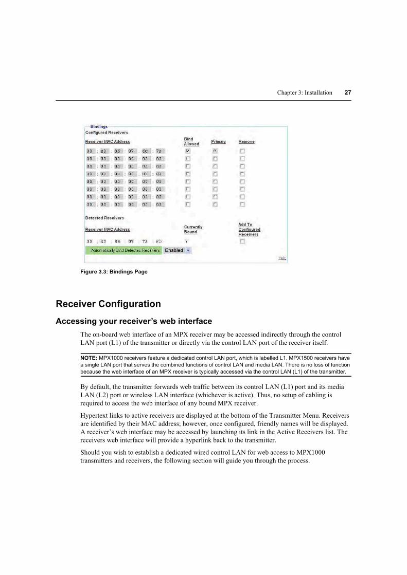
4. Scroll to the bottom of the Bindings page and verify that all active receivers are listed (by
MAC address) within the Detected Receivers table. Figure 3.3 on page 27 illustrates this table.
If a receiver is not listed, verify proper LAN connectivity or power state of the receiver. If the
receiver is not detected and your transmitter is configured for wireless operation, you may
need to adjust the transmitter power setting, refer to wireless transmission power settings on
page 42.
Setting explicit receiver bindings (Optional)
By default, a transmitter honors requests from any receiver that requests binding. You may,
however, configure a transmitter to honor bind requests only from a select list of receivers.
Requests from non-selected receivers will be rejected by the transmitter. This feature is referred to
as explicit bindings.
Explicit bindings offer the following benefits:

26 MPX Extender Installer/User Guide
• Loss of connection with dynamically bound receivers is not treated as an error condition
by the transmitter. Explicitly bound receivers, however, will be flagged as non-responsive
should they drop connection with the transmitter.
• Explicit bindings allow for the selection of a Primary Receiver, which is required for bi-
directional serial and IR communications. Further, the Primary Receiver may be used to
establish a particular display device as the source for EDID information.
• Multi-transmitter configurations require explicit pairings of receivers to transmitters.
The transmitter’s Bindings page contains separate tables for detected receivers and configured
receivers. In addition, there is a global setting that enables automatic binding of detected receivers.
The Detected Receivers table contains an entry for each receiver that has discovered the transmitter
and requested binding. Each entry provides the MAC address and bind status of the receiver. A
check box is provided for you to add detected receivers to the Configured Receivers table. The
Configured Receivers table provides explicit controls for receiver binding. A bound receiver
participates in media sessions with the transmitter. Explicitly unbound receivers may be bound by a
different transmitter.
The global option, labeled Automatically Bind Detected Receivers, is used to indicate whether or
not receiver bind requests are automatically granted.
NOTE: Automatic binding results in a dynamic extension network in which receivers bind and unbind as they are
turned on and off. Although simple to establish, dynamic extension networks lack a primary receiver, which
prevents the transmission of bi-directional serial and IR data.
To establish explicit receiver bindings:
1. Within the Detected Receivers table, select the Add to Configured Receivers checkbox next to
each detected receiver. Figure 3.3 on page 27 illustrates the Detected Receivers table.
2. Optional. You may manually enter a receiver’s MAC address. MAC address labels are affixed
to the bottom of an MPX receiver.
3. Optional. Configure the Automatically Bind Detected Receivers setting using drop-down list.
If enabled, the transmitter will automatically bind all detected receivers detected that are not
explicitly disabled for binding in the Configured Receivers table.
4. Apply the changes.
5. For each receiver that is intended to receive media from this transmitter, set the Bind Allowed
checkbox in the Configured Receivers table. The remaining receivers may be bound to a
different transmitter. Figure 3.3 on page 27 illustrates the Configured Receivers table.
6. Click the Primary radio button to assign one unit as the Primary receiver for bi-directional
exchange of IR and serial data and reception of EDID information.
7. Apply the changes.
Chapter 3: Installation 27
Figure 3.3: Bindings Page
Receiver Configuration
Accessing your receiver’s web interface
The on-board web interface of an MPX receiver may be accessed indirectly through the control
LAN port (L1) of the transmitter or directly via the control LAN port of the receiver itself.
NOTE: MPX1000 receivers feature a dedicated control LAN port, which is labelled L1. MPX1500 receivers have
a single LAN port that serves the combined functions of control LAN and media LAN. There is no loss of function
because the web interface of an MPX receiver is typically accessed via the control LAN (L1) of the transmitter.
By default, the transmitter forwards web traffic between its control LAN (L1) port and its media
LAN (L2) port or wireless LAN interface (whichever is active). Thus, no setup of cabling is
required to access the web interface of any bound MPX receiver.
Hypertext links to active receivers are displayed at the bottom of the Transmitter Menu. Receivers
are identified by their MAC address; however, once configured, friendly names will be displayed.
A receiver’s web interface may be accessed by launching its link in the Active Receivers list. The
receivers web interface will provide a hyperlink back to the transmitter.
Should you wish to establish a dedicated wired control LAN for web access to MPX1000
transmitters and receivers, the following section will guide you through the process.

28 MPX Extender Installer/User Guide
MPX1000 receiver control LAN (L1) settings (Optional)
To establish a dedicated wired control LAN for management of MPX1000 extenders, it will be
necessary to establish unique IP addresses for the control LAN ports (L1) of each receiver and
transmitter to be placed on the shared LAN.
NOTE: The LAN port of an MPX1500 receiver responds is programmed with different IP addresses for control
LAN and media LAN functions. Although it is not possible to manually assign the IP address for media LAN
functionality, it is possible to assign the IP address, subnet mask and gateway for control LAN functionality.
These addresses need not reside on the same subnet.
To establish a wired control LAN for MPX1000 receivers:
1. Interconnect the control LAN ports of the MPX transmitter and all receivers using industry-
standard 10/100Mbps Ethernet components.
2. Attach your browser client to the control LAN.
3. Turn on a single MPX receiver and leave all other receivers with default addresses turned off.
4. Launch a browser session to the default IP address of an MPX receiver, which is 192.168.1.2
with a subnet mask of 255.255.255.0.
5. If prompted, type the default password, which is Admin (case sensitive).
6. If the unit has not yet been configured, you will be prompted to enter a country code. The
wireless radio is disabled until a country code is entered. In addition to enabling the radio, the
country code will establish legal bands, channels, and power limits.
7. Within the receiver menu, select the Control LAN Settings page and set the parameters
as follows:
a. Enter the IP address of the control LAN to match the subnet on which it will be placed.
Use this address for subsequent browser connections. Do not use the following reserved IP
addresses: 0.0.0.0, 192.168.1.10, 192.168.1.1, 192.168.1.2, 192.168.10.xxx
or 192.168.11.xxx.
b. Enter the control LAN subnet mask.
c. Enter the control LAN gateway address, or 0.0.0.0 if there is no gateway.
8. For MPX1000 receivers, you may manually select the LAN speed and duplex settings. To
ensure interoperability, compatible settings must be selected on the Ethernet switch and
MPX1000 extenders.
9. Apply the changes.
10. Label the unit with its new IP address.
11. Return to step 3 until all MPX receivers are configured with unique IP addresses.

Chapter 3: Installation 29
Configure receiver system settings (Optional)
Although optional, it is recommended to configure each receiver with a friendly name. These
names will be displayed within the web interface of the transmitter. Other system settings affect
diagnostic splash screens and remote diagnostics.
To configure receiver system settings:
1. Using a browser client, access the web interface of the MPX receiver either directly or via the
transmitter web interface.
2. Within the Receiver Menu, launch the System Settings page.
3. Type a Device Name to associate a friendly name with the unit, such as “Aisle 4 Display.” The
device name may contain any combination of printable characters but it cannot exceed 127
characters. This name will be displayed for your convenience throughout the web interface.
The name will also be displayed on the front panel of an MPX1000 transmitter.
4. The HTTPS Required setting allow you to explicitly set HTTPS as the transport protocol for
access to the web interface. Should you do so, it will be necessary to install a certificate from
the MPX extender onto your browser client. HTTPS ensures encryption of all web content. If
this setting is disabled, you may obtain a secure web session with the transmitter by launching
an https session rather than an http session from your browser client.
5. The Display Status Screens setting allows you enable and disable the display of status
messages on the display device. Status messages include diagnostic information that may be
useful during initial installation but may not be desired once units are deployed.
6. The Remote Console feature allows for centralized control of the MPX extenders that are
deployed at remote locations. Contact Avocent technical support before you enable
this feature.
7. Apply the changes.
Multiple transmitter considerations
If there are multiple transmitters to which your receiver may bind, you may select a
particular transmitter.
To select a specific receiver:
1. Browse to the Media LAN Settings of the receiver.
2. In the MAC Address of Transmitter field, enter the MAC address of the transmitter to which
this receiver shall attempt to bind. The MAC Address may be displayed via the transmitter’s
System Settings web page.
3. Apply the changes.

30 MPX Extender Installer/User Guide
Configure receiver password (Optional)
Refer to Change Password on page 34 for detailed instructions.
Firmware Version Checking
Select the Version Information web page on the transmitter and each receiver. Make note of the
firmware version. Visit the Avocent web site at www.avocent.com and review the available
upgrades. Should you decide to upgrade your units, see Upgrading MPX Firmware on page 88 for
detailed instructions.
Initiating A Media Session
Your MPX transmitter is now ready to establish a media session with its bound receivers.
The following steps allow you to verify proper operation of your media modules, establish the
Active EDID string at the MPX transmitter and test compatibility of your source and display
devices through the extension network.
To establish your first media session across the extension network:
1. Turn off your MPX transmitter and receivers.
2. Turn off your display devices.
3. Properly shut down off your source device if it is not already turned off at this time.
4. Attach your display device to the primary MPX receiver using an appropriate cable.
NOTE: If your display device does not support DDC2B or if a cable or video switching device prevents the
normal flow of EDID information across the DDC bus, then refer to Common Tuning Needs on page 71 for
additional information. Please do so before moving on to the next step.
5. Power on the display device.
6. Power on the primary MPX receiver.
NOTE: This power up sequence ensures that the display device is online when the MPX1000 receiver reads
EDID information from the device.
7. Attach the source device to the MPX transmitter using an appropriate cable.
8. Turn on the MPX transmitter.
9. Wait for the MPX receiver to bind with the MPX transmitter, as previously described.
10. Power on your source device and activate as necessary to ensure flow of video data.
NOTE: This power up sequence ensures that proper EDID information is stored in the MPX transmitter before
the source device attempts to read it. The order of power up sequencing is important only once, during initial
configuration and setup. If it is necessary to replace a field-installed MPX transmitter with brand new unit, these
same steps should be used to properly establish valid EDID information in the replacement unit.

Chapter 3: Installation 31
11. Active video should appear on the display device attached to the MPX receiver within 30
seconds after the source device has completed initializing.
12. Additional receivers and display devices may now be added to the extension network.
Troubleshooting
If video fails to appear on your display device or if plug-and-play functionality is not functioning
normally, see Video Troubleshooting on page 68 for detailed troubleshooting procedures.

32 MPX Extender Installer/User Guide
Transmitter and Receiver Placement
To find acceptable locations for your extenders:
1. Turn off all MPX extenders.
2. Turn off your source and display devices.
3. Place the transmitters and receivers in their desired locations without firmly mounting
the units.
4. Turn on the MPX extenders and raise antennas to their upright positions. Allow the units to
initialize and bind.
5. Using the receiver signal strength indicator for guidance, position the units and antennas as
needed to obtain optimal signal strength. If possible, seek to obtain three or more signal
strength LEDs on the front of the receiver.
NOTE: Radio signals propagate outward from an omni-directional antenna in a disk-l ke perpendicular manner. A
vertical antenna results in horizontal signal propagation. For this reason, it is best to start with transmitter and
receiver antennas that are similarly oriented and aligned on the same horizontal or vertical plane. Vertical
antennas result in horizontal emission. High gain antenna produce a narrowed yet stronger beam of radio waves
than low gain antennas. Thus, it is more critical to position transmitters and receivers on the same plane when
using high gain antennas.
NOTE: If transient obstructions, such as people, boxes or vehicles are anticipated during normal operation, then
simulate these factors as best you can to observe their effect upon signal strength under real-world conditions.
If necessary, signal strength may be optimized as follows:
a. Increase your transmitter power: See Table 4.3 on page 41 for more information.
b. Use specialized directional or high gain antennas: See Antenna Options on page 61 for
more information.
c. Use antenna extension cables to raise antennas above obstructions or pass antennas
through walls. Although extension cables allow for optimal antenna placement, they will
attenuate signal strength. Thus, they should only be used when necessary and kept to a
minimum length. Proper placement of your receiver, if possible, is preferable to use of
extension cables. Never connect extension cables together as a means of extending
antenna placement. Thus will result in excessive signal loss. See Antenna Options on
page 61 for specific options and installation instructions.
d. Reposition your extenders: See Radio Considerations on page 60 for
additional information. A slight movement of several inches may result in a noticeable
increase of signal strength.
e. Depending upon your environment, it might be advantageous to orient the antennas on
your transmitters and receivers such that one antenna on each unit is upward in a 12
O’clock position and the other antenna is perpendicular to it, in a 3 or 9 O’clock position.
The vertical antenna will radiate on a horizontal plane and the horizontal antenna will
radiate on a vertical plane. This may increase the benefit of antenna diversity by taking

Chapter 3: Installation 33
advantage of diverse reflections off of environmental objects such as walls, floors, desks,
and ceilings.
f. Use of lower frequency channels may slightly increase transmission distance and
wall penetration. For maximum wall penetration, consider use of G band channels
and antennas.
g. As a final optimization, you might want to compare receiver signal strength across all
frequencies. Starting at the lowest frequency, make note of the weakest signal strength
reported by any receiver. Select the next frequency via the Media LAN Settings page on
the transmitter. Allow the receivers to bind. Again, record the weakest signal strength
reported by any receiver. Repeat this process until all channels have been tested. Set the
transmitter for the channel that resulted in the strongest recorded signal strength. Take
care to evaluate only those channels that are compatible with the antennas that you have
selected. For example, do not test G band channels with UNII band antennas.
6. Once acceptable signal strength is attained, turn off the MPX transmitter and receivers.
7. Mount your MPX extenders securely without altering their orientation. See Appendix C,
Mounting Options on page 74.
8. If your antennas will be subject to wind or other forces that might cause them to rotate out of
position, then you might consider use of a few drops of silicon gel to lock the position of
the antenna.
9. Attach the video and audio source devices to the MPX transmitter.
NOTE: With your MPX1000 unit, you have received two snap-on ferrites. If you are using the analog audio (RCA
Jacks) these ferrites should be applied to each end of the cables. Apply the ferrites approximately one inch from
the cable ends. One ferrite goes around both cables.
10. Attach the video and audio sink devices to the MPX receiver(s).
11. Turn on your sink devices.
12. Turn on your MPX receivers.
13. Turn on your MPX transmitter and wait for the receivers to bind.
14. Turn on your source device.
15. Start a media stream from the source device to the MPX transmitter.
16. Using the browser client, launch to the transmitter’s Connection Status page. Figure 3.4 on
page 34 illustrates the Bound Receiver Status table. Verify frame rate and signal strength for
each of the bound receivers. The Media LAN Performance web page provides additional
useful information. Make final adjustments, if necessary.

34 MPX Extender Installer/User Guide
Figure 3.4: Bound Receiver Status
Final Adjustments
Presentation of audio and video media should now be active at each display device, as if they were
each individually attached to the source device. Inspect each display for signs of hesitation, color
shift, audio loss, or other anomalies. Refer to System Tuning on page 37 for additional information.
Extension of IR and Serial Data
After mounting your MPX extenders, continue with the next chapter if you intend to use the
extension network to pass serial or IR control signals.
Change Password
During authentication, the browser asks for your password. The Change Password page lets the
administrator change the password.
NOTE: The password dialog box displays bullets or asterisks while you type information. If a secure connection
is not used, the browser sends the unencrypted password to the Web server during this configuration process.
Credentials are always encrypted during subsequent logons.
To change the password:
1. Type the old login password.
2. Type the new login password. The length of the password must be between 0 and 31
characters. The password may contain any combination of letters, digits, and
printable characters.
NOTE: When you are typing a password, the case is significant.
3. Type the new login password again. Both password parameters must match.
4. Click Apply.

Chapter 3: Installation 35
Figure 3.5: Change Login Password Page

36 MPX Extender Installer/User Guide

37
CHAPTER
4Additional Functions
System Tuning
Transmitter tuning parameters
Controls provided on the Tuning Parameters web page, illustrated in Figure 4.1, allow you to fine
tune the operation of your extension system.
To understand the video data rate parameters, it is useful to think of the media LAN as a pipe that is
able to carry a finite amount of data. Under normal conditions, the pipe is filled primarily with
video data. Audio and control packets require much less bandwidth. Video data consists of real-
time data (data which is being sent for the first time) and retransmitted data. Under ideal conditions,
the transmitter fills the pipe with real-time data. Under adverse conditions, as may be caused by RF
interference, some packets are corrupted. In response, receivers will issue retransmission requests
to the transmitter. The transmitter will respond to these requests even as even as real-time data
continues to flow. If the demand for missed data becomes large, the transmitter will need to
carefully manage the handling of retransmission requests to avoid a situation in which real-time
data is unable to flow.
To ensure the continued flow of the media session, the transmitter is able to dynamically alter its
processing of real-time and retransmitted data. Real-time data can be more highly compressed, if
needed, within user-defined bounds. Higher compression will soften the image and allow more
headroom for retransmitted data in the pipe. Retransmitted data can be metered within bounds;
thus, allowing more room in the pipe for real-time data.
When wireless bandwidth is restricted for any reason, the default tuning parameter values are
designed to maintain a constant frame rate. This is accomplished by increasing compression of real-
time data, thereby allowing more headroom for retransmission requests. Under worst case
conditions, the video data stream will be compressed down the minimum data rate. As conditions
permit, the transmitter will reduce compression levels to the maximum data rate.

38 MPX Extender Installer/User Guide
The transmitter offers basic and advanced settings. The basic settings are described in the
following table:
Table 4.1: Transmitter Tuning Parameters - Basic Settings
Setting Description
Wireless Video Data Rate These settings allow the MPX transmitter to dynamically adjust the
degree of compression applied to real-time video data. The actual data
rate at any given time will fall between the maximum and minimum data
rate values, unless the image requires less than minimum data rate (such
as a screen that is mostly black or white).
High data rates consume more bandwidth and result in the sharpest
possible image. Lower data rates result in a softened image that requires
less bandwidth.
During moments of interference, there may be insufficient bandwidth for
the transmitter to maintain 30 frames per second at the maximum data
rate while servicing requests for lost data. The minimum data rate setting
determines how the transmitter responds to this condition. Setting this
value high will cause the transmitter to drop frames as needed to
maintain the sharpest possible image. Setting this value low will cause
the transmitter to soften images as needed to maintain the highest
possible frame rate. High values may be preferable for still computer
graphics. High values may be preferable for motion video.
Maximum rates for wireless media sessions include integer values up to
20 Mbps. Maximum rates for wired media sessions include integer values
up to 40 Mbps.
Content Type The MPX transmitter supports two compression algorithms. One
algorithm is geared toward computer graphics. Office automation tools
such as presentation or spreadsheet applications will benefit from this
setting. The other compression algorithm is geared toward motion video.
Cameras and digital video players will benefit from this algorithm. Select
the algorithm that is best suited for your primary application.
Luma-Chroma This parameter affects the way in which the transmitter processes luma
and chroma information in the input video stream. By default, 67% of the
output stream is dedicated to luma information and 33% of the output
stream is dedicated to chroma information. This ratio is well suited for a
combination of motion video and some computer graphics. For
applications that are heavily slanted toward still graphic images with
sharp edges, you may have better results by increasing luma to 80%.
Experiment with the slider bar to find the settings that are best for
your application.
Retry Limit This parameter sets an upper bound on the percentage of available
media LAN bandwidth that a transmitter will allocate for servicing of
retransmitted data.
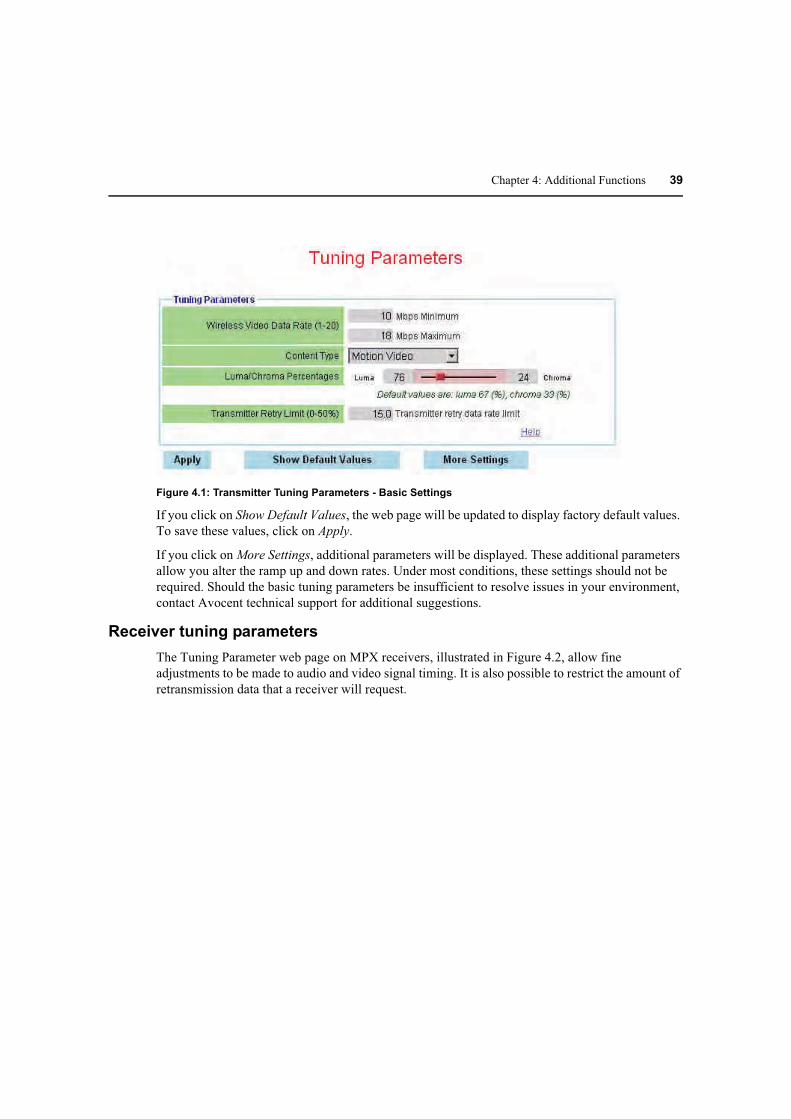
Chapter 4: Additional Functions 39
Figure 4.1: Transmitter Tuning Parameters - Basic Settings
If you click on Show Default Values, the web page will be updated to display factory default values.
To save these values, click on Apply.
If you click on More Settings, additional parameters will be displayed. These additional parameters
allow you alter the ramp up and down rates. Under most conditions, these settings should not be
required. Should the basic tuning parameters be insufficient to resolve issues in your environment,
contact Avocent technical support for additional suggestions.
Receiver tuning parameters
The Tuning Parameter web page on MPX receivers, illustrated in Figure 4.2, allow fine
adjustments to be made to audio and video signal timing. It is also possible to restrict the amount of
retransmission data that a receiver will request.

40 MPX Extender Installer/User Guide
The following table provides an overview of receiver tuning parameters:
Table 4.2: Receiver Tuning Parameters
Setting Description
Receiver Video Latency The MPX transmitter places a timestamp on audio and video data to
ensure proper lip-synch across all bound receivers. Thus audio and video
output will be synchronized across all display devices as long as the
devices themselves introduce equivalent latency prior to display.
Introduction of scalers, converters or other active processing devices
between the output of an MPX receiver and its associated display device
may cause a noticeable video or audio lag when compared to other
receivers. With this parameter, it is poss ble to mimic this delay on other
receivers, thus bringing all display devices into synchronization.
Default value for this parameter is 200ms. This delay provides an elastic
buffer of roughly 7 frames, allowing receivers to remain in lock step even
if lost packets need to be retransmitted. Reducing receiver latency below
the default of 200ms may compromise synchronization across receivers.
However, in applications consisting of one or two receivers, it may be
desirable to reduce this value if the primary application involves mouse-
driven presentations that are sensitive to latency. If choppy video occurs
on one or more receivers, raise the value until smooth video is obtained.
Receiver Audio Latency
Receiver Retry Limit This parameter limits the amount of retransmitted data that a receiver is
able to request from a transmitter.
Figure 4.2: Receiver Tuning Parameters
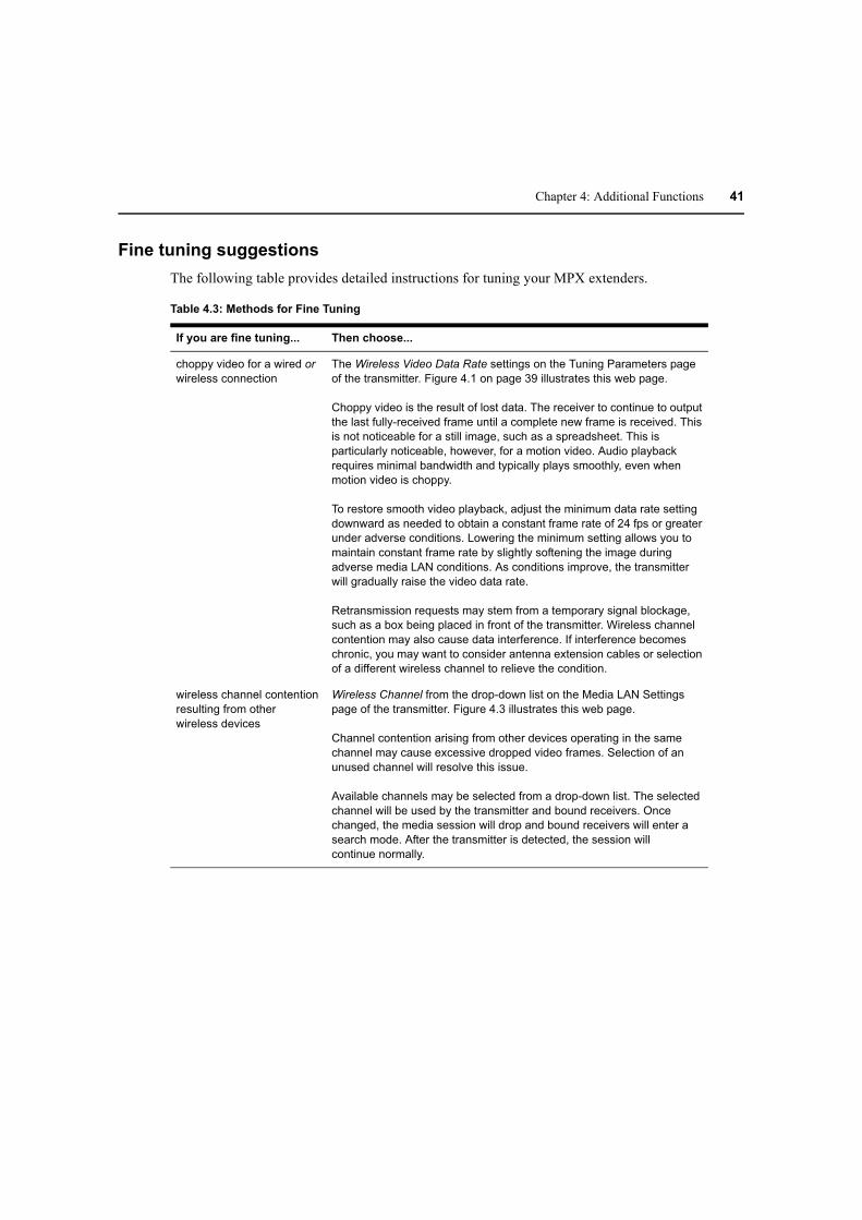
Chapter 4: Additional Functions 41
Fine tuning suggestions
The following table provides detailed instructions for tuning your MPX extenders.
Table 4.3: Methods for Fine Tuning
If you are fine tuning... Then choose...
choppy video for a wired or
wireless connection
The Wireless Video Data Rate settings on the Tuning Parameters page
of the transmitter. Figure 4.1 on page 39 illustrates this web page.
Choppy video is the result of lost data. The receiver to continue to output
the last fully-received frame until a complete new frame is received. This
is not noticeable for a still image, such as a spreadsheet. This is
particularly noticeable, however, for a motion video. Audio playback
requires minimal bandwidth and typically plays smoothly, even when
motion video is choppy.
To restore smooth video playback, adjust the minimum data rate setting
downward as needed to obtain a constant frame rate of 24 fps or greater
under adverse conditions. Lowering the minimum setting allows you to
maintain constant frame rate by slightly softening the image during
adverse media LAN conditions. As conditions improve, the transmitter
will gradually raise the video data rate.
Retransmission requests may stem from a temporary signal blockage,
such as a box being placed in front of the transmitter. Wireless channel
contention may also cause data interference. If interference becomes
chronic, you may want to consider antenna extension cables or selection
of a different wireless channel to relieve the condition.
wireless channel contention
resulting from other
wireless devices
Wireless Channel from the drop-down list on the Media LAN Settings
page of the transmitter. Figure 4.3 illustrates this web page.
Channel contention arising from other devices operating in the same
channel may cause excessive dropped video frames. Selection of an
unused channel will resolve this issue.
Available channels may be selected from a drop-down list. The selected
channel will be used by the transmitter and bound receivers. Once
changed, the media session will drop and bound receivers will enter a
search mode. After the transmitter is detected, the session will
continue normally.

42 MPX Extender Installer/User Guide
wireless transmission
power settings
Maximum Transmit Power field on the Media LAN Settings page. This
setting may be set separately for transmitters and receivers. Figure 4.3
illustrates this web page.
The range of values at the transmitter is determined by the country code
and wireless channel. The range of values at the receiver may be wider
than the transmitter because the receiver is not explicitly configured for
country code and wireless channel settings. Nonetheless, the receiver
will not exceed legal power limits at any time. The Actual Antenna Power
field of a receiver’s Connection Status page displays the receiver’s true
radiated power level.
Lower settings allow transmitters to be placed more closely. This is useful
when multiple video streams are required. Higher values allow for
increased distances between transmitters and receivers. In addition,
Avocent offers optional extended distance antennas for this purpose.
The default power setting may overdrive radio receivers when MPX
transmitters and receivers are positioned in close proximity to each other,
within ten feet or less, as might be the case during initial configuration
and testing. Over-driven signals may result in lost frames or in extreme
cases, in dropped connections. To avoid such errors, select the lowest
setting that results in a stable, acceptable image. Remember to raise
transmit power levels when extenders are placed in their final locations.
Depending upon environmental conditions, you may find it beneficial to
configure receiver transmit power settings slightly lower than the
transmitter. This will reduce contention among receivers and ensure that
the transmitter has the most dominant signal.
Sharpness of
computer graphics
Luma Chroma Percentages and Content Type on the Tuning Parameters
page of the transmitter. Figure 4.1 on page 39 illustrates this web page.
The luma chroma setting affects the way in which the transmitter
processes luma and chroma information in the input video stream. By
default, 67% of the output stream is dedicated to luma information and
33% of the output stream is dedicated to chroma information. This ratio is
well suited for a combination of motion video and some computer
graphics. For applications that are heavily slanted toward still graphic
images with sharp edges, you may have better results by increasing luma
to 80%. Experiment with the slider bar to find the settings that are best for
your application.
The content type may be used to select an encoding algorithm that is
geared toward computer graphics (still images) or motion video.
Table 4.3: Methods for Fine Tuning (Continued)
If you are fine tuning... Then choose...

Chapter 4: Additional Functions 43
Figure 4.3: Transmitter Media LAN Settings
Serial Control
Serial passthrough allows data to be sent from a device attached to the serial port of a transmitter to
device(s) attached to the serial port of the primary receiver or all bound receivers. Conversely, data
arriving at the serial port of the primary receiver will be forwarded to the transmitter and made
Audio video synchronization
across display devices
Receiver Video Latency and Receiver Audio Latency settings on the
receiver Tuning Parameters web page. Figure 4.2 on page 40 illustrates
these settings.
Default value for this parameter is 200ms. This delay provides an elastic
buffer of roughly 7 frames, allowing receivers to remain in lock step even
if lost packets need to be retransmitted. Increasing either of these
parameters will allow you to adjust audio and video playback across
display devices.
Reducing receiver latency below the default of 200ms may compromise
synchronization across receivers. However, in applications consisting of
one or two receivers, it may be desirable to reduce this value if the
primary application involves mouse-driven presentations that are
sensitive to latency. If choppy video occurs on one or more receivers,
raise the value until smooth video is obtained.
Table 4.3: Methods for Fine Tuning (Continued)
If you are fine tuning... Then choose...

44 MPX Extender Installer/User Guide
available to the device attached to its serial port. Serial data is passed in real-time and is not
buffered for subsequent reading.
Serial passthrough modes are enabled via the web interface of an MPX transmitter. Serial port
settings, such as baud rate, flow control, data size, stop bits and parity are also configurable only
via the transmitter’s web interface. When serial passthrough is enabled, these settings are
forwarded to all receiver units within the extender network. When serial mode is disabled, there is
no processing of serial data on either the transmitter or the receiver(s).
Serial settings on all serially attached devices must correspond with the serial settings established
via the web interface on the transmitter.
In summary, serial operation of the product is as follows:
• If simple passthrough is selected, then data received at the serial port of the transmitter will be
broadcast through the extension network to all bound receivers and, in turn, to all serially
attached display devices.
• If primary only passthrough is selected, then data received at the serial port of the transmitter
will be sent only to the primary receiver. This mode allows bidirectional communication with a
single device. Using the Primary radio button provided on the Bindings page, it is possible to
switch serial control from one receiver to another. In addition to serial connectivity, IR control
and EDID passing are tied to the primary receiver. Thus, it is important to consider the full
impact of selecting a new primary receiver.
• If serial passthrough is disabled, then serial data received at the serial port on the transmitter
will be ignored.
• If any passthrough mode is enabled and a primary receiver is selected, then data received from
the device attached to the serial port of the primary receiver will be forwarded across the
extension network to the MPX transmitter and, in turn, to the device attached to transmitter’s
serial port.
• If a primary receiver is not selected and serial passthrough is enabled, then serial data will be
broadcast from the transmitter to all bound receivers; however, bi-directional transfers will not
be available.
• All serial settings must be made via the web interface on the transmitter. The web interface on
the receiver does not offer serial configuration options.

Chapter 4: Additional Functions 45
Figure 4.4 illustrates the basic flow of serial data among MPX units and attached devices.
Figure 4.4: Serial Passthrough Mode
Use the Serial Passthrough parameters section on the transmitter’s Serial Settings page to specify
the serial mode and settings.
To configure serial passthrough modes:
1. Select Serial Settings from the Transmitter Menu, located on the left side of the web page.
Figure 4.5 on page 46 illustrates these settings.
2. Choose one of the following Serial Passthrough Modes from the drop-down list:
a. Disabled: Serial port on the transmitter and receiver units is not used.
b. Simple passthru: Serial data received at the serial port of the transmitter will be broadcast
to all bound receivers. Serial data will be sent only from the primary receiver to
the transmitter.
c. Primary only: Serial data received at the serial port of the transmitter will be sent only to
the primary receiver. Serial data will be sent only from the primary receiver to
the transmitter.
3. Choose the serial baud rate for the local serial port from the Baud Rate drop-down list.
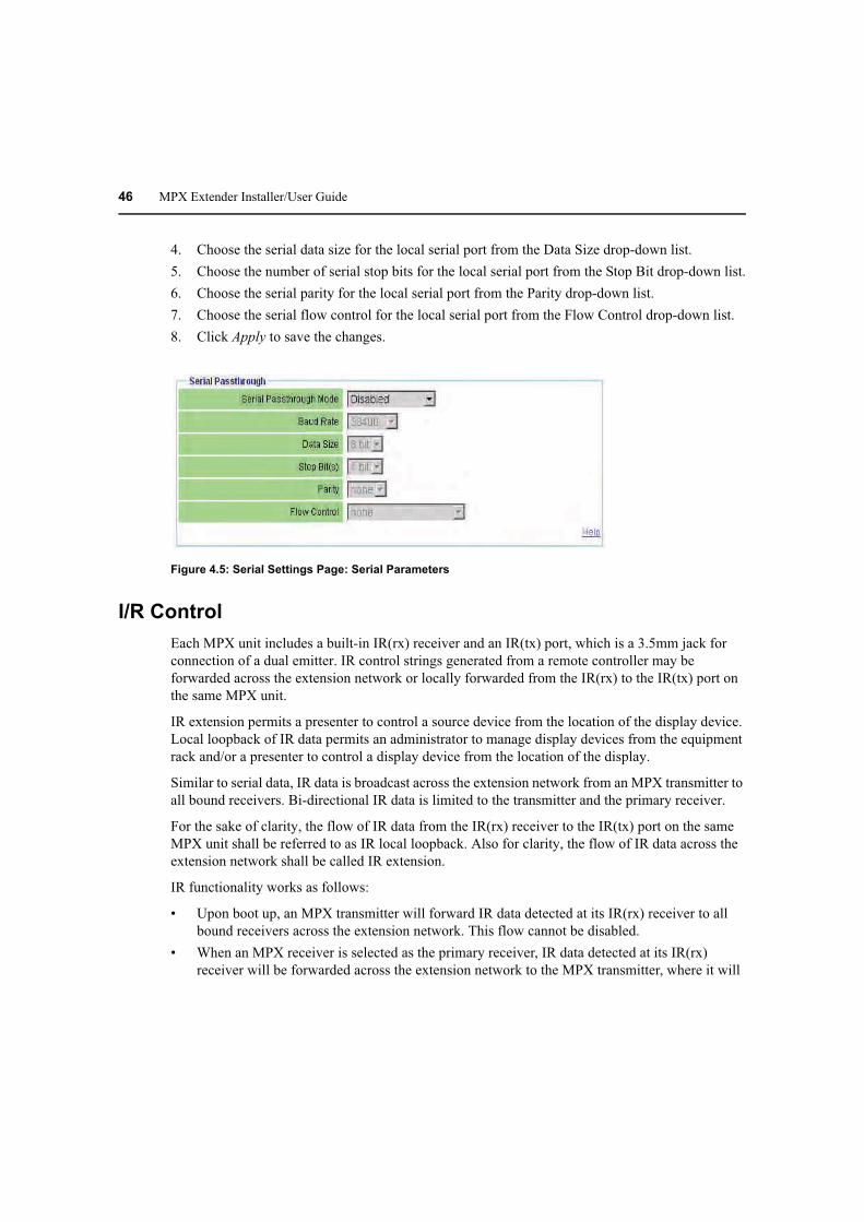
46 MPX Extender Installer/User Guide
4. Choose the serial data size for the local serial port from the Data Size drop-down list.
5. Choose the number of serial stop bits for the local serial port from the Stop Bit drop-down list.
6. Choose the serial parity for the local serial port from the Parity drop-down list.
7. Choose the serial flow control for the local serial port from the Flow Control drop-down list.
8. Click Apply to save the changes.
Figure 4.5: Serial Settings Page: Serial Parameters
I/R Control
Each MPX unit includes a built-in IR(rx) receiver and an IR(tx) port, which is a 3.5mm jack for
connection of a dual emitter. IR control strings generated from a remote controller may be
forwarded across the extension network or locally forwarded from the IR(rx) to the IR(tx) port on
the same MPX unit.
IR extension permits a presenter to control a source device from the location of the display device.
Local loopback of IR data permits an administrator to manage display devices from the equipment
rack and/or a presenter to control a display device from the location of the display.
Similar to serial data, IR data is broadcast across the extension network from an MPX transmitter to
all bound receivers. Bi-directional IR data is limited to the transmitter and the primary receiver.
For the sake of clarity, the flow of IR data from the IR(rx) receiver to the IR(tx) port on the same
MPX unit shall be referred to as IR local loopback. Also for clarity, the flow of IR data across the
extension network shall be called IR extension.
IR functionality works as follows:
• Upon boot up, an MPX transmitter will forward IR data detected at its IR(rx) receiver to all
bound receivers across the extension network. This flow cannot be disabled.
• When an MPX receiver is selected as the primary receiver, IR data detected at its IR(rx)
receiver will be forwarded across the extension network to the MPX transmitter, where it will

Chapter 4: Additional Functions 47
be emitted to the source device through the dual emitter. This IR data will not be forwarded to
other MPX receivers. This flow cannot be disabled.
• The web interface of each unit offers an IR Local Loopback setting. This setting affects IR
local loopback only. Altering this setting has no effect upon the flow of IR data across the
extension network.
Figure 4.6 illustrates the flow of IR data from the MPX transmitter to a single MPX receiver. This
data, however, will be received by all bound receivers. This functionality allows an administrator to
send control strings such as on/off to display devices from the equipment rack.
Figure 4.6: IR Flow: Transmitter to Receiver
Figure 4.7 illustrates the flow of IR data from the primary MPX receiver to the MPX transmitter.
This allows a presenter to send control strings, such as play/pause, to source devices from the
location of the display device. A single IRB-100 dual emitter is supplied with the MPX transmitter.
Should it be necessary to control more than two source devices, Avocent offers the IRB-Y splitter,
which allows two IRB-100 dual emitters to be attached to a single MPX transmitter. Additional
IRB-100 emitters may also be purchased separately. The MPX transmitter, or receiver, is capable
of driving up to 4 emitters (two IRB-100s).
Figure 4.7: IR Flow: Primary Receiver to Transmitter
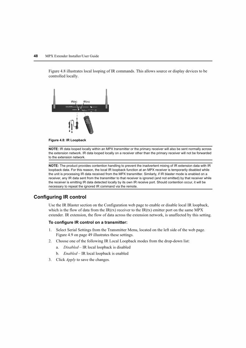
48 MPX Extender Installer/User Guide
Figure 4.8 illustrates local looping of IR commands. This allows source or display devices to be
controlled locally.
Figure 4.8: IR Loopback
NOTE: IR data looped locally within an MPX transmitter or the primary receiver will also be sent normally across
the extension network. IR data looped locally on a receiver other than the primary receiver will not be forwarded
to the extension network.
NOTE: The product provides contention handling to prevent the inadvertent mixing of IR extension data with IR
loopback data. For this reason, the local IR loopback function at an MPX receiver is temporarily disabled while
the unit is processing IR data received from the MPX transmitter. Similarly, if IR blaster mode is enabled on a
receiver, any IR data sent from the transmitter to that receiver is ignored (and not emitted) by that receiver while
the receiver is emitting IR data detected locally by its own IR receive port. Should contention occur, it will be
necessary to repeat the ignored IR command via the remote.
Configuring IR control
Use the IR Blaster section on the Configuration web page to enable or disable local IR loopback,
which is the flow of data from the IR(rx) receiver to the IR(tx) emitter port on the same MPX
extender. IR extension, the flow of data across the extension network, is unaffected by this setting.
To configure IR control on a transmitter:
1. Select Serial Settings from the Transmitter Menu, located on the left side of the web page.
Figure 4.9 on page 49 illustrates these settings.
2. Choose one of the following IR Local Loopback modes from the drop-down list:
a. Disabled – IR local loopback is disabled
b. Enabled – IR local loopback is enabled
3. Click Apply to save the changes.

Chapter 4: Additional Functions 49
Figure 4.9: Serial Settings Page: IR Parameters
Regardless of the IR blaster mode setting, all IR data received by the local IR receiver port on the
transmitter is forwarded to all connected receivers. This IR data will be sent to the IR transmit port
at each of those receivers.
To configure IR control on a receiver:
1. Select Serial Settings from the Receiver Menu, located on the left side of the web page, Figure
4.9 on page 49 illustrates these settings.
2. Choose one of the following IR Local Loopback modes from the drop-down list:
a. Disabled: IR local loopback is disabled
b. Enabled: IR local loopback is enabled
3. Click Apply to save the changes.
Status Monitoring
The MPX transmitter provides two web pages for system monitoring: the Connection Status web
page and the Media LAN Performance web page. The Connection Status page offers a status table
for transmitter and a separate table for status of each receiver. The MPX receivers provide similar
web pages.
Connection status
The Connection Status page on the transmitter displays the operational status of the transmitter and
all bound receivers. Figure E.3 on page 70 illustrates this web page. The content on this page
dynamically refreshes every five seconds. Status table entries are largely common to both MPX
transmitters and receivers; however, some functions are specific to transmitters or receivers. The
following table describes the status information that is provided for MPX transmitters (Tx), MPX
receivers (Rx) or both:
Table 4.4: Status Page Information
Field
Tx /
Rx Description
Device Name Both Provides a friendly name for an MPX transmitter or receiver for ease of
identification within the web interface.

50 MPX Extender Installer/User Guide
Control LAN MAC
Address
Both L1 MAC address (control LAN) of the transmitter or receiver, also printed on an
external label on the unit.
Wired Media LAN
MAC Address
Tx L2 MAC address (media LAN) of the transmitter.
Serial Number Tx The serial number assigned to the unit.
OEM ID Tx The OEM identifier assigned to the unit. This information may be required for
technical support but is not required for normal use of the product.
Country Code Both The country code for the product. See Supported ISO Country Codes on page 92.
Product Type Both The product type for the unit: MPX1000T, MPX1000R or MPX1500R.
A/V Module Type Both The type of media module inserted, such as HD15 or HDMI.
Operational Status Both For transmitters, this field will indicate the number of bound/active receivers. For
receivers, this field will indicate if the receiver is currently connected to a
transmitter. For all units, this field will provide flash upgrade status.
Session IP
Address
Both The media LAN IP address.
Session
Transmitter
Device Name
Rx The device name of transmitter to which this receiver is currently bound.
Wireless Channel
Number
Both The wireless channel number in use. Only displayed on wireless
extension networks.
Actual Antenna
Power
Both The effective radiated power inclusive of extension attenuation and gains due to
power settings and specialized antennas.
A/V Source Type Tx Type of source device: HDMI, DVI-D, VGA, Component.
A/V Source
Resolution
Tx Resolution, such as 1024x768 @60Hz, of the source device.
A/V Encoder
Running
Tx An indication that video is being encoded and transmitted in real-time.
A/V Source Error Tx Helpful diagnostic messages.
Primary Video
Resolutions
Tx A list of all resolutions that the Primary Receiver has reported to the transmitter.
Video Resolutions
in Use
Tx A list of resolutions that have been reported to the source device.
Table 4.4: Status Page Information (Continued)
Field
Tx /
Rx Description

Chapter 4: Additional Functions 51
Media LAN performance
Refer to section Available Information on page 68 for information regarding the Media LAN
Performance table.
RGB Video
Resolutions
Stored
Tx Resolutions that are currently stored in the Active EDID string of the transmitter.
This field is present for VGA display devices only.
Signal Strength
Indication
Rx An indication of the wireless signal strength on the receiver unit. Only displayed
on wireless A/V networks. Ranges from 0 to 100, with 0 representing weak signal
strength and 100 representing maximum signal strength. A graphical display is
also provided as follows:
• Poor signal – No bars or one red bar
• Passable signal quality – A red bar and one or two yellow bars; signal quality
should be improved
• Good signal quality – A red bar, two yellow bars and one or two green bars
Frame Rate Rx The video frame rate on the receiver unit. With no lost frames, the frame rate will
alternate between 29 and 30 frames per second. Wireless bandwidth contention
and poor signal quality may result in lower frame rates. Refer to Methods for Fine
Tuning on page 41 for tips on restoring acceptable frame rates.
Table 4.4: Status Page Information (Continued)
Field
Tx /
Rx Description
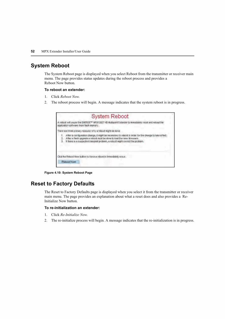
52 MPX Extender Installer/User Guide
System Reboot
The System Reboot page is displayed when you select Reboot from the transmitter or receiver main
menu. The page provides status updates during the reboot process and provides a
Reboot Now button.
To reboot an extender:
1. Click Reboot Now.
2. The reboot process will begin. A message indicates that the system reboot is in progress.
Figure 4.10: System Reboot Page
Reset to Factory Defaults
The Reset to Factory Defaults page is displayed when you select it from the transmitter or receiver
main menu. The page provides an explanation about what a reset does and also provides a Re-
Initialize Now button.
To re-initialization an extender:
1. Click Re-Initialize Now.
2. The re-initialize process will begin. A message indicates that the re-initialization is in progress.

Chapter 4: Additional Functions 53
Figure 4.11: Reset to Factory Defaults Page
Front Panel Display
The transmitter displays an Initializing message during power-up, followed by the Avocent logo.
Press any button while the Avocent logo is displayed to enter the menu display system.
Display modes
The front panel menu system has three major display modes:
• Manual Menu Navigation
• Automatic (Timed) Menu Display
• Parameter Modification
In all display modes, the Up and Down buttons automatically repeat every 750 milliseconds if
pressed continuously.
Manual Menu Navigation
While you are in Manual Menu Navigation mode, the button definitions are as follows:
Table 4.5: Buttons for Manual Menu Navigation
Button Description
Up Scrolls up through a set of menu items within a menu.
NOTE: While in this mode, the symbol is displayed in the upper left character
position of the display to indicate that the Up button will scroll up to the next item in
the menu. (If the menu being displayed only contains a single item, scrolling is not
possible. This is indicated by the absence of the symbol.)
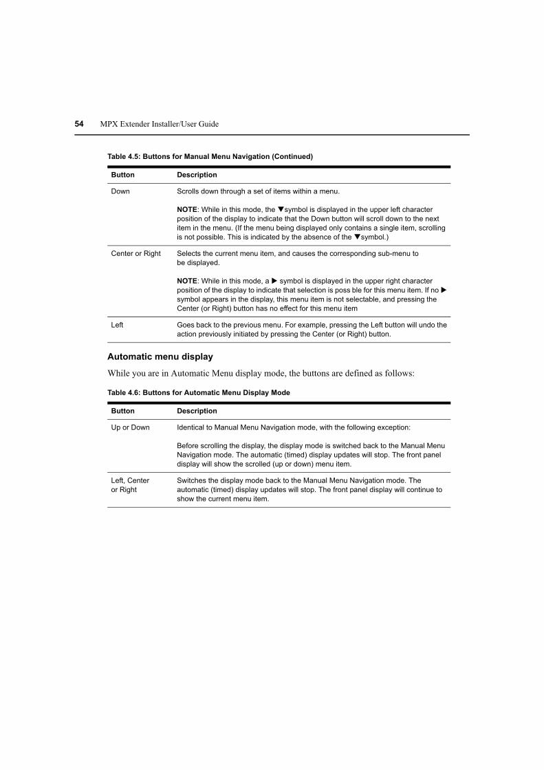
54 MPX Extender Installer/User Guide
Automatic menu display
While you are in Automatic Menu display mode, the buttons are defined as follows:
Table 4.6: Buttons for Automatic Menu Display Mode
Button Description
Up or Down Identical to Manual Menu Navigation mode, with the following exception:
Before scrolling the display, the display mode is switched back to the Manual Menu
Navigation mode. The automatic (timed) display updates will stop. The front panel
display will show the scrolled (up or down) menu item.
Left, Center
or Right
Switches the display mode back to the Manual Menu Navigation mode. The
automatic (timed) display updates will stop. The front panel display will continue to
show the current menu item.
Down Scrolls down through a set of items within a menu.
NOTE: While in this mode, the !symbol is displayed in the upper left character
position of the display to indicate that the Down button will scroll down to the next
item in the menu. (If the menu being displayed only contains a single item, scrolling
is not possible. This is indicated by the absence of the !symbol.)
Center or Right Selects the current menu item, and causes the corresponding sub-menu to
be displayed.
NOTE: While in this mode, a " symbol is displayed in the upper right character
position of the display to indicate that selection is poss ble for this menu item. If no "
symbol appears in the display, this menu item is not selectable, and pressing the
Center (or Right) button has no effect for this menu item
Left Goes back to the previous menu. For example, pressing the Left button will undo the
action previously initiated by pressing the Center (or Right) button.
Table 4.5: Buttons for Manual Menu Navigation (Continued)
Button Description

Chapter 4: Additional Functions 55
Parameter modification
While you are in Parameter Modification mode, the button definitions are as follows:
Table 4.7: Buttons for Parameter Modification Mode
Button Description
Up Changes the parameter value to the next valid value in the upward direction.
Note: While in this mode, the symbol is displayed in the lower right character
position of the display to indicate that pressing the Up button will increase the value
of the parameter.
Down Changes the parameter value to the next valid value in the downward direction.
Note: While in this mode, the ! symbol is displayed in the lower right character
position of the display to indicate that pressing the Down button will decrease the
value of the parameter.
Left, Center
or Right
Switches the display mode back to the Manual Menu Navigation mode. The front
panel display will continue to show the current menu item.
Note: While in this mode, a " symbol is displayed in the upper right character
position of the display to indicate that selection is poss ble for this menu item. If no "
symbol appears in the display, this menu item is not selectable, and pressing the
Center (or Right) button has no effect for this menu item.
Left Goes back to the previous menu. For example, pressing the Left button will undo the
action previously initiated by pressing the Center (or Right) button.
Main menu
The top level menu selections for the front panel display are as follows:
• Display Rx Status
• Display Tx Settings
• Configure Control LAN
To scroll through these top level menu selections when the Avocent logo is present, press any of
the four arrow buttons. To navigate through these items, press the Up or Down buttons. To select
and display a corresponding sub-menu, press the Center or Right buttons. Press the Left button to
return the front panel display to the Avocent logo.
Display Rx status
The sub-menu for this selection provides continually updated real-time receiver status. The
following information is provided:
• Receiver identification: MAC address and friendly name

56 MPX Extender Installer/User Guide
• Primary status: The primary receiver is identified by the presence of Pri in the
name display
• Signal strength: reported by the receiver back to the transmitter
• Frame rate
Press the Up and Down buttons to manually scroll through status for all receivers. Press the Right
button to enter into a timed scrolling mode, which displays status of all receivers in a round robin
manner. If you press any button while in the timed scrolling mode, the display reverts back to
the sub-menu.
Press the Left button to return to the main menu.
Display Tx settings
The sub-menu for this selection allows you to display the following information:
• Transmitter identification: MAC address and friendly name
• Control LAN address (L1) Settings: IP address, subnet mask and gateway
• Media LAN Settings: Wireless channel number or Wired for wired configurations
• Video quality setting: presented as a target throughput value such as 20Mbps
• IR local loopback setting: On / Off
You may press the Up and Down buttons to manually scroll through these items. Press the Left
button to return to the main menu.
Configure control LAN
The sub-menu for this selection allows you to configure the following settings for transmitter’s
Control LAN (L1) port:
• IP address
• Subnet mask
• Gateway
To configure control LAN settings:
1. Press the Right button to select an octet for configuration. Octets are underlined when selected.
2. Press the Up and Down buttons to change the value of the selected octet as needed.
3. Press the Right button to select the next octet.
4. Repeat steps 2 and 3 until the IP address, the subnet mask and gateway address are all
properly configured.
5. Press the Right button until Save Change is displayed.
6. Press the Up and Down buttons to alternate between Yes and No.
Chapter 4: Additional Functions 57
7. Press the Center button to complete the operation. The settings will be applied immediately if
Yes was selected and the settings were valid. Otherwise, the current configuration will not be
altered. In either case, you will be returned to top level of the Configure Control LAN menu.
Press the Left button to return to the Avocent logo or the Up and Down buttons to scroll through the
top level menu.
NOTE: Front panel configuration may be disabled via the transmitter’s web interface. By default, front panel
configuration is enabled. This setting may be changed in the System Settings page.
Screen saver
The front panel display has a screen saver that automatically comes on if no buttons are pressed for
30 consecutive minutes. When the screen saver is active, it horizontally scrolls the current screen
off the left edge of the display while scrolling in a blank screen from the right. The process repeats
every four seconds.
While the screen saver is active, updates to the content of the display occur only during the four
seconds that the screen stops in the center of the display. Automatic (timed) updates to the contents
of the screen are delayed while the screen is actively scrolling, and will not occur until the screen
reaches its center position. This lets you see every automatic status update, even if the screen saver
is active while the RxStatus is in scan mode.
Press any key while the screen saver is active to immediately stop the screen saver and display the
current screen in its normal (centered) position on the front panel.

58 MPX Extender Installer/User Guide

59
Appendix A: Technical Support
Our technical support staff is ready to assist you with installation or functional issues that you may
encounter with your Avocent product. If an issue should develop, follow the steps below for the
fastest possible service.
To resolve an issue:
1. Check the pertinent section of the manual to see if the issue can be resolved by following the
procedures outlined.
2. Check our web site at www.avocent.com/support to search the knowledge base or use the
online service request.
3. Call the Avocent Technical Support location nearest you.
Appendices

60 MPX Extender Installer/User Guide
Appendix B: Radio Considerations
The number, thickness and location of walls, ceilings and other objects that signals pass through
affect the range of MPX extenders. A typical wall has metal or wood studs covered on each side by
a single layer of gypsum or plaster board. Useful transmission range will vary depending on the
types of materials, obstructions and background radio frequency noise at your place of installation.
To maximize your wireless range:
1. Keep the number of walls and ceilings between the transmitter and receiver to a minimum;
each wall or ceiling can reduce your wireless product’s range.
2. Position a direct line between your transmitter and receiver so that the signal will travel
straight through a wall or ceiling. A wall that is 1.5 feet thick (.5 meters) at a 45°angle appears
to be almost 3 feet (1 meter) thick; at a 2°angle, it looks over 42 feet (14 meters) thick!
3. If possible, position your devices and extenders so that the signal passes through drywall or
open doorways and not other materials. Building materials such as a solid metal door or
aluminum studs can impede the wireless signal and will have a negative effect on the
wireless range.
4. Keep your MPX transmitter and receivers away (at least 3 to 6 feet or 1 to 2 meters) from
electrical devices or appliances that generate RF noise.
5. Antenna extension cables result in signal loss. When possible, move the transmitter or receiver
into the desired position in lieu of using an extension cable. When cables are necessary, use the
shortest Avocent-certified cable that allows you to properly position your antenna. Daisy-
chaining of antenna extension cables is not supported. Carefully follow installation
instructions provided with your cable kit and properly configure the extender when using
extension cables as described in “Antenna Options” on page 61.
NOTE: Signals will not pass through concrete walls or titanium coated glass.
The MPX extender provides wireless transmission over the Unlicensed National Information
Infrastructure (UNII) and on the Industrial, Scientific, and Medical (ISM) radio bands.
The product is able to operate over following bands:
• UNII 1: (4 channels) 5.15-5.25 GHz
• UNII 3: (4 channels) 5.725 to 5.825 GHz
• ISM: (11 channels) 2.412 to 2.462 GHz (Available for use within the United States)
Firmware upgrades, including Dynamic Frequency Selection (DFS), will be provided, allowing the
product to transmit in the following frequencies:
• UNII 2: (4 channels) 5.25-5.35 GHz
• ETSI: (11 channels) 5.470-5.725 GHz

Appendices 61
Antenna Options
Various antenna options are available for MPX extenders, including specialized antennas, antenna
extension kits and lightening arrestors. The following sections describe these options and offer an
overview of installation instructions.
NOTE: ISM band antennas and UNII band antennas are tuned for operation in their specific bands. An ISM
antenna is not effective for UNII-band radio transmission and vice-versa. Take care to choose an appropriate
antenna for the wireless channel that has been selected.
Installation of antenna options
Installation of antenna options have a direct impact on effective radiated power of MPX extenders.
NOTE: Because antenna options have a direct impact on the effective radiated power of MPX extenders, it is
important to use only Avocent-certified options. Furthermore, antenna options should be used only as descr bed
herein. Misuse of these options could result in excessive radiated power or degraded performance.
To Install antenna options:
1. Physically install the antenna, arrestor or extender as described in the instructions provided
with the option. It is acceptable to intermix antenna types within an extension network. For
example, a transmitter equipped with omni-directional antennas may communicate with
receivers using directional antennas. If you intermix antenna types on the same unit, then con-
figure the unit for the highest gain antenna. For example, if you install a 3dB and 8dB gain
antenna on the same extender, then configure the extender for use with your 8dB antenna.
2. Launch a browser client to the transmitter.
3. Select the System Settings page. Figure 3.2 on page 24 illustrates the System Settings page.
4. Within the Antenna Type pull-down menu, select the antenna installed on your extender. The
following specialized antennas are available for use with MPX extenders:
a. LGA51G-OMN: A low gain omni-directional antenna tuned for best performance in the
UNI 1 and 2 bands. This is the default antenna.
b. HGA51G-DIR30: A high gain, directional antenna tuned for best performance in the UNII
1 and 2 bands.
c. LGA55G-OMN: A low gain omni-directional antenna tuned for best performance in the
UNI 3 and ETSI bands.
d. HGA55G-OMN: A high gain omni-directional antenna tuned for best performance in the
UNI 3 and ETSI bands.
e. LGA24G-OMN: A low gain omni-directional antenna tuned for best performance in the
ISM band.
f. IGA24G-OMN: An intermediate gain omni-directional antenna tuned for best
performance in the ISM band.
g. Several generic antennas are listed in the pull-down menu. These entries represent
antennas that are anticipated for future release by Avocent. Use of third-party antennas is

62 MPX Extender Installer/User Guide
neither implied or supported by means of these entries. If you purchase an optional
antenna from Avocent that is not specifically listed in the pull-down list, then select the
generic antenna that most closely resembles the antenna that you have installed.
High gain and directional antennas act to concentrate radio waves in a narrow beam or plane in
the same way that a megaphone concentrates sound waves. These antennas are appropriate
when you need to maximize transmission distance. Low gain omni antennas allow radio waves
to propagate in a more spherical manner. Because the radio’s energy is sent equally in all
directions, the effective transmission range drops off more quickly than if it were concentrated
into a narrow beam. Use of these antennas allow transmitters to be placed in closer proximity.
Low gain antennas allow you to take advantage of reflections that might bounce off of floors,
walls and ceilings. Use of lower frequency antennas are preferable for penetration of walls or
other obstructions. In multi-transmitter environments, use of high frequency antennas allows
for good RF separation from extenders using low frequency antennas within the same RF
envelope.
5. Within the Lightening Arrestor pull-down menu, indicate if an arrestor is present or not.
6. Within the Antenna Extension pull-down menu, indicate which extension is installed, if any.
Supported antenna extenders include:
a. 1 Meter: Provides a 1 meter antenna extension.
b. 2 Meter: Provides a 2 meter antenna extension.
c. 3 Meter: Provides a 3 meter antenna extension.
NOTE: Although antenna extension cables allow for optimized antenna placement, they result in signal loss.
When properly installed and configured, the firmware will attempt to boost the transmit power to compensate for
this loss. Daisy-chaining of extension cables to increase the cable length is not supported as this will result in
excessive degradation of signal strength.
7. If you have installed a custom antenna, then you will need to configure the extender for a chan-
nel in the appropriate band. Select Media LAN Settings from the main menu. From Wireless
Channel pull-down menu, select an appropriate channel.
8. Repeat steps 3 through 7 for each active receiver.
Proper configuration allows your extenders to properly adjust radio transmit power as needed to
compensate for extension cable loss. Proper configuration also allows your extenders to accurately
report effective radiated power as effected by antenna gain.
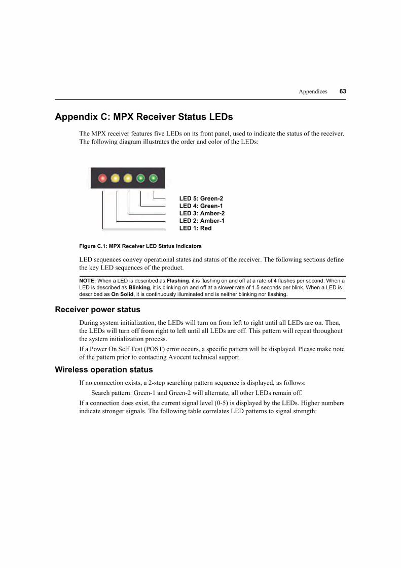
Appendices 63
Appendix C: MPX Receiver Status LEDs
The MPX receiver features five LEDs on its front panel, used to indicate the status of the receiver.
The following diagram illustrates the order and color of the LEDs:
LED 5: Green-2
LED 4: Green-1
LED 3: Amber-2
LED 2: Amber-1
LED 1: Red
Figure C.1: MPX Receiver LED Status Indicators
LED sequences convey operational states and status of the receiver. The following sections define
the key LED sequences of the product.
NOTE: When a LED is described as Flashing, it is flashing on and off at a rate of 4 flashes per second. When a
LED is described as Blinking, it is blinking on and off at a slower rate of 1.5 seconds per blink. When a LED is
descr bed as On Solid, it is continuously illuminated and is neither blinking nor flashing.
Receiver power status
During system initialization, the LEDs will turn on from left to right until all LEDs are on. Then,
the LEDs will turn off from right to left until all LEDs are off. This pattern will repeat throughout
the system initialization process.
If a Power On Self Test (POST) error occurs, a specific pattern will be displayed. Please make note
of the pattern prior to contacting Avocent technical support.
Wireless operation status
If no connection exists, a 2-step searching pattern sequence is displayed, as follows:
Search pattern: Green-1 and Green-2 will alternate, all other LEDs remain off.
If a connection does exist, the current signal level (0-5) is displayed by the LEDs. Higher numbers
indicate stronger signals. The following table correlates LED patterns to signal strength:

Table C.1: LED Status - Wireless Connection
Signal Level Red Amber-1 Amber-2 Green-1 Green-2
0 OFF OFF OFF OFF OFF
1 ON OFF OFF OFF OFF
2 ON ON OFF OFF OFF
3 ON ON ON OFF OFF
4 ON ON ON ON OFF
5 ON ON ON ON ON
64 MPX Extender Installer/User Guide
Wired operation status
If no connection exists, a 2-step searching pattern sequence is displayed, as follows:
Search pattern: Green-1 and Green-2 will alternate, all other LEDS remain off.
If a connection does exist, the current signal level (0-5) of the connection is displayed using one of
6 LED patterns, as follows:
Table C.2:
Signal Level Red Amber-1 Amber-2 Green-1 Green-2
5 OFF ON ON ON ON
LED Status - Wired Connection
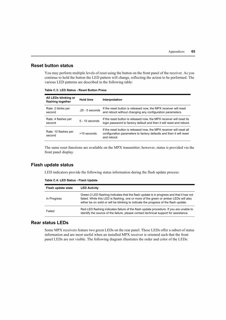
Appendices 65
Reset button status
You may perform multiple levels of reset using the button on the front panel of the receiver. As you
continue to hold the button the LED pattern will change, reflecting the action to be performed. The
various LED patterns are described in the following table:
Table C.3: LED Status - Reset Button Press
All LEDs blinking or
flashing togetherHold time Interpretation
Rate: 2 blinks per
second.25 - 5 seconds
If the reset button is released now, the MPX receiver will reset
and reboot without changing any configuration parameters.
Rate: 4 flashes per
second5 - 10 seconds
If the reset button is released now, the MPX receiver will reset its
login password to factory default and then it will reset and reboot.
Rate: 10 flashes per
second>10 seconds
If the reset button is released now, the MPX receiver will reset all
configuration parameters to factory defaults and then it will reset
and reboot.
The same reset functions are available on the MPX transmitter; however, status is provided via the
front panel display.
Flash update status
LED indicators provide the following status information during the flash update process:
Table C.4: LED Status - Flash Update
Flash update state LED Activity
In Progress
Green-2 LED flashing indicates that the flash update is in progress and that it has not
failed. While this LED is flashing, one or more of the green or amber LEDs will also
either be on solid or will be blinking to indicate the progress of the flash update.
FailedRed LED flashing indicates failure of the flash update procedure. If you are unable to
identify the source of the failure, please contact technical support for assistance.
Rear status LEDs
Some MPX receivers feature two green LEDs on the rear panel. These LEDs offer a subset of status
information and are most useful when an installed MPX receiver is oriented such that the front
panel LEDs are not visible. The following diagram illustrates the order and color of the LEDs:

ST-2
ST-1
66 MPX Extender Installer/User Guide
Figure C.2: MPX Receiver Rear LED Status Indicators
ST-1 operation:
• Blinking: Indicates system boot
• Solid Media LAN established
ST-2 operation:
• Off: Connection with transmitter is not established
• Slow blink: Signal level = 1
• Fast blink: Signal level = 2 or 3
• Solid: Signal level = 4 or 5
ST-1 and ST-2 together:
• Alternating: Searching for a transmitter
• Slow blink: Firmware upgrade in progress
• Fast blink: Firmware upgrade error occurred

Appendices 67
Appendix D: Audio
The HDMI media module for MPX1000 extenders offers support for embedded digital audio and
unbalanced analog audio via left and right RCA jacks. The HD15 media module supports only
unbalanced analog audio. Analog audio is sampled at 48Khz, which is CD quality audio.
NOTE: With your MPX1000 unit you have received two snap-on ferrites. If you are using the analog audio (RCA
Jacks) these ferrites should be applied to each end of the cables. Apply the ferrites approximately one inch from
the cable ends. One ferrite goes around both cables.
The MPX1500 receiver offers embedded HDMI digital audio as well as unbalanced analog audio
via left and right RCA jacks. Snap on ferrites are not required for the use with MPX1500 receivers.
Depending upon your firmware version, the MPX1500 receiver may or may not support coaxial
and optical digital audio (S/PDIF).
Because transmitters and receivers can be configured for differing media types, a variety of
configurations are possible. The following sections provide detailed information regarding these
additional configurations.
HDMI Considerations
When an HDMI source is received, the MPX transmitter ignores the external analog audio jacks
and passes the embedded digital audio signal. When a DVI-D signal is received, the transmitter will
accept audio input from the RCA jacks. In both cases, audio will be output by the receiver in the
form of embedded digital audio and external analog audio.
NOTE: If the primary receiver is attached to a VGA or DVI-D display, the EDID information provided by the
display will disable digital audio at the source device. In this case, the transmitter will pass analog audio even if
the source device connection is HDMI. Thus, if digital audio is required, be sure to select a receiver attached to
an HDMI display device.
NOTE: If the digital audio embedded within the HDMI signal is 96KHz, then analog output on the receiver
modules will be disabled. Digital audio will continue normally.
HD15 Considerations
A transmitter equipped with an HD15 media module will always input data on the dual RCA jacks.
When passed to a receiver with an attached HDMI display device, the audio will be embedded
within the HDMI signal and also available on the dual RCA jacks.
When HD15 devices are attached to both the transmitter and receiver, audio will be present only on
the dual RCA jacks.

68 MPX Extender Installer/User Guide
Appendix E: Video Troubleshooting
The following troubleshooting tips should help you to resolve most common setup and
initialization issues. If your problem persists, please contact Avocent technical support for
additional help.
Available Information
The on-board web interface of the MPX transmitter and receiver provide information that should
help to diagnose and resolve video connectivity issues. The Display Device Settings page on the
receiver is a good place to start.
NOTE: Using the web controls provided via the Display Device Settings page, you may override the EDID
information provided by your display device. Doing so, allows you to explicitly control the resolutions offered to
the end-user of the system. When you override the normal EDID function of a display device, the receiver no
longer attempts to read EDID information from the device. Thus, the receiver is unable to detect whether a
display device is attached or not. Normally a receiver will cease to request video data from the transmitter for a
Plug-and-Play display device that is not attached or not powered on. The act of overriding the Plug-and-Play
function, however, will cause the receiver to request video data regardless of whether a display device is
attached or not. Thus, this setting may impact overall performance in installations where display devices are not
always attached or powered on.
The Display Device Settings page for MPX1000 receivers, illustrated in Figure E.1. This page
allows the receiver to generate a custom EDID, which may be needed to compensate for non Plug-
and-Play display devices and to override EDID strings from Plug-and-Play devices. The following
example illustrates a means to simulate a display device that offers only 640x480 and
1024x768 resolutions.
NOTE: The ability to construct an EDID string is supported only for VGA display devices.
Figure E.1: Display Device Settings Page for MPX1000 Receivers

Appendices 69
The Display Device Settings page for MPX1500 receivers, illustrated in Figure E.2. This page
defaults to Plug-and-Play operation. In this mode, the receiver will read EDID information from the
attached display device and pass that information along to the transmitter. Alternatively, you may
manually select custom resolutions for VGA, component, s-video or composite video.
NOTE:It is not poss ble to select custom resolutions for HDMI or DVI-D modes of operation.
Modular adapters are optionally available from Avocent to adapt VGA, component, and composite
cables for connection to the DVI-I video output port of the receiver. When using these cables, the
receiver will automatic detect the selected video type. When using third-party converters, it will be
be necessary to configure the receiver for the appropriate video type and resolution via this page.
Figure E.2: Display Device Settings Page for MPX1500 Receivers
The Transmitter Status table, illustrated in Figure E.3, on the Connection Status page of an MPX
transmitter offers additional information. If video is actively being processed by the transmitter, the
A/V Source Resolution field indicates the current resolution.
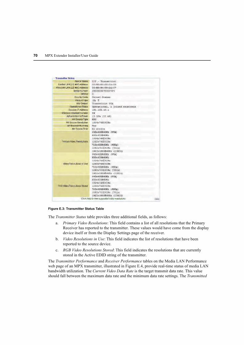
70 MPX Extender Installer/User Guide
Figure E.3: Transmitter Status Table
The Transmitter Status table provides three additional fields, as follows:
a. Primary Video Resolutions: This field contains a list of all resolutions that the Primary
Receiver has reported to the transmitter. These values would have come from the display
device itself or from the Display Settings page of the receiver.
b. Video Resolutions in Use: This field indicates the list of resolutions that have been
reported to the source device.
c. RGB Video Resolutions Stored: This field indicates the resolutions that are currently
stored in the Active EDID string of the transmitter.
The Transmitter Performance and Receiver Performance tables on the Media LAN Performance
web page of an MPX transmitter, illustrated in Figure E.4, provide real-time status of media LAN
bandwidth utilization. The Current Video Data Rate is the target transmit data rate. This value
should fall between the maximum data rate and the minimum data rate settings. The Transmitted
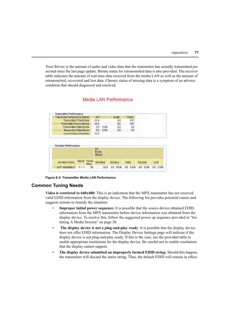
Appendices 71
Total Bitrate is the amount of audio and video data that the transmitter has actually transmitted per
second since the last page update. Bitrate status for retransmitted data is also provided. The receiver
table indicates the amount of real-time data received from the media LAN as well as the amount of
retransmitted, recovered and lost data. Chronic status of missing data is a symptom of an adverse
condition that should diagnosed and resolved.
Figure E.4: Transmitter Media LAN Performance
Common Tuning Needs
Video is restricted to 640x480: This is an indication that the MPX transmitter has not received
valid EDID information from the display device. The following list provides potential causes and
suggests actions to remedy the situation:
• Improper initial power sequence: It is possible that the source device obtained EDID
information from the MPX transmitter before device information was obtained from the
display device. To resolve this, follow the suggested power up sequence provided in “Ini-
tiating A Media Session” on page 30.
• The display device is not a plug-and-play ready: It is possible that the display device
does not offer EDID information. The Display Device Settings page will indicate if the
display device is not plug-and-play ready. If this is the case, use the provided table to
enable appropriate resolutions for the display device. Be careful not to enable resolutions
that the display cannot support.
• The display device submitted an improperly formed EDID string: Should this happen,
the transmitter will discard the entire string. Thus, the default EDID will remain in effect.

72 MPX Extender Installer/User Guide
In this case, use the Display Device Settings table on the MPX receiver to enable appropri-
ate resolutions for the display device.
• The VGA cable is damaged or does not pass data on the DDC channel: Pins 12 and
15: of a VGA cable represent DDC data and clock, respectively. EDID information is
passed via the DDC channel. Verify proper operation of your VGA cable.
No video is visible: This is an indication that the display device is either not properly connected or
is not compatible with MPX extenders. The following troubleshooting steps may help to resolve
this issue.
• For all display devices:
• Launch your browser to the Connection Status page on the transmitter. Helpful error infor-
mation may be displayed in the Transmitter Status table.
• Connect a display device directly to your source device. If active media is not displayed,
then resolve the issue before attempting to extend the signal. If active media is present,
then verify proper operation of the transmitter and receiver video cables and adapters,
if any.
• Power off all receivers other than the primary. Working with a reduced network will allow
you to simplify the troubleshooting environment.
• View the resolution and frame rate tables in the appendix of this manual to determine if
your source device is operating within supported parameters.
• If you have selected wireless operation, select a different channel in the Wireless Media
LAN settings to ensure that there is not a conflict with other nearby wireless devices.
• It might be useful to attempt using a wired media LAN to check for possible radio-
related issues.
• Make sure that you have selected a primary receiver. The primary is responsible for gener-
ation of EDID information for the source device.
• For HDMI or DVI-D display devices:
• Initiate a video hot plug of the source and display devices to ensure that the EDID infor-
mation has been read and transferred across the extension network.
• Power cycle the transmitter to clear invalid HDCP keys, which may have been collected
from a non-valid display device. An invalid key will prevent the transmitter from sending
protected content.
• Determine if you are sending protected content. If so, do all of the display devices have
appropriate content protection keys?
• If only one display is not working, try making it the primary. Perform a hotplug of the
video connection (HDMI, VGA). If the problem is resolved and the displays are different
models, there may be a incompatibility between the options these monitors support.

Appendices 73
Motion video is choppy: This is an indication that frames are being dropped. “Fine tuning
suggestions” on page 41 provides steps to resolve this issue.
Additional tips for VGA display devices
Display devices differ widely in their support of video resolution, refresh rates, color depth and
other configurable features. To allow source and display devices to negotiate available settings in a
plug-and-play manner, a display data channel standard has been adopted by the industry. The
standard supported by MPX extenders is DDC2B. This standard is adhered to by most VGA, DVI,
and HDMI display devices. Compliant display devices contain a PROM that can be read by a
source device across a display data channel (DDC). The PROM contains formatted information
about the capabilities of the display. This information is commonly referred to as extended display
information data, or EDID string for short.
DVI-D and HDMI source devices will dynamically query this information when a display device
hot-plug event is detected. Thus, displays are immediately available. Most VGA computer source
devices such as graphics cards, however, query information only once, upon power up. For this
reason it is particularly important that EDID information is passed through the extension network
and assembled by the transmitter into the Active EDID string before power up of VGA source
device. Therefore, the power sequence of MPX extenders, display devices, and source device
is critical when using a VGA source device.
NOTE: EDID information is maintained by the MPX transmitter in non-volatile storage; thus, the order of power
up sequencing is important only during initial installation.
If you followed the recommended power up procedure and no video is visible at the display device,
then the following tips may help you to resolve your problem.
• The VGA source may be operating at a resolution not supported by the MPX transmitter.
• If you are on a laptop, toggle the video back to the laptop display and check the resolution
of the secondary monitor. To test the connection between the transmitter and the receiver,
change the secondary monitor setting to 640 x 480 @ 60Hz resolution. Again, toggle the
video to the VGA connector. Video should appear within 30 seconds.
• If your source device is a desktop PC or server, then you must disconnect the MPX
transmitter from its VGA port and connect a VGA monitor in its place. It may be
necessary to reboot the computer to establish video. Change the resolution to 640 x 480 @
60Hz. After changing the resolution on the PC, restart the PC (or power cycle your VGA
source). Quickly reconnect to the MPX transmitter while the VGA source is initializing.
After you have obtained video at the 640 x 480 resolution, you may change the resolution on the
VGA source to one of the other supported resolutions.

74 MPX Extender Installer/User Guide
Appendix F: Mounting Options
MPX1000 mounting options
Transmitter mounting
The MPX1000 transmitter ships with rack mount brackets for installation into an equipment rack.
When installed, the transmitter requires only one unit of rack height.
Figure F.1: Transmitter Rack Mount Brackets
The MPX1000 transmitter also supports the following mounting options:
• Table mounting via the optional RMK-56 mounting kit, described below
• VESA MIS-E compatible mounting, using third-party brackets as described below
Receiver mounting
The MPX1000 receiver features the following mounting options, allowing it to adapt to most work
environments:
• Table mounting via the optional RMK-56 mounting kit, described below
• VESA MIS-E compatible mounting, using third-party brackets as described below
Table mounting
The Avocent RMK-56 table mounting bracket kit is compatible with MPX1000 transmitters and
receivers. The kit contains two brackets, which are interchangeable such that either may be used as
a left or right bracket. In addition, the brackets may be attached with keyholes facing up or down.
This flexibility allows a device to be mounted in a table top or below table manner.
Detailed instructions are provided with the kit. The following diagram illustrates the basic
components of the kit.

Appendices 75
Figure F.2: Parts for Under Desk Mounting Option
The following diagram offers dimensions, in inches, of the RMK-56 horizontal mounting brackets
when used in conjunction with the MPX1000R receiver.
Figure F.3: Installing the Horizontal Mounting Bracket (Under Desk Option)
NOTE: Mounting accessories are ordered separately. Contact your dealer for more information.
VESA mounting
MPX1000 transmitters and receivers provide VESA MIS-E threaded holes, allowing you to choose
from a wide range of third-party ceiling, wall, tilt, cabinet and desk mount products. The VESA

76 MPX Extender Installer/User Guide
MIS-E standard is designed for mounting of mid-size displays that weigh under 50 pounds.
Compliant products, such as the MPX1000 transmitter and receiver, are equipped with a 200 x
100mm mounting hole pattern.
Please follow the mounting instructions provided with the third-party mounting kit.
Mounting options for MPX1500 extenders
Wall and table mounting
An optional keyhole style mounting bracket (part number DMK-04) is available for use with
MPX1500 extenders that allows for wall mounting. The bracket also provides screw slots for
table mounting.
Figure F.4: MPX1500 Mounting Bracket
To install the mounting bracket:
1. Use the bracket as a template to mark desired holes on the mounting surface.
2. Insert mounting screws into the drilled holes.
3. Attach the bracket to unit using the supplied pan head machine screws.
NOTE: Take care to orient the bracket such that the narrow portion of keyhole slot will interlock with the heads of
the mounting screws when the unit suspended upon them.
4. Slots on outer edge of bracket can be used after the bracket is installed to unit. Hold unit /
bracket against the mounting surface and drive screws thru slots. Screws along bottom edge
should be installed before plugging in cables.
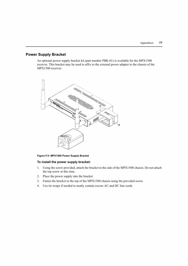
Appendices 77
Power Supply Bracket
An optional power supply bracket kit (part number PBK-01) is available for the MPX1500
receiver. This bracket may be used to affix to the external power adapter to the chassis of the
MPX1500 receiver.
Figure F.5: MPX1500 Power Supply Bracket
To install the power supply bracket:
1. Using the screw provided, attach the bracket to the side of the MPX1500 chassis. Do not attach
the top screw at this time.
2. Place the power supply into the bracket.
3. Fasten the bracket to the top of the MPX1500 chassis using the provided screw.
4. Use tie wraps if needed to neatly contain excess AC and DC line cords.
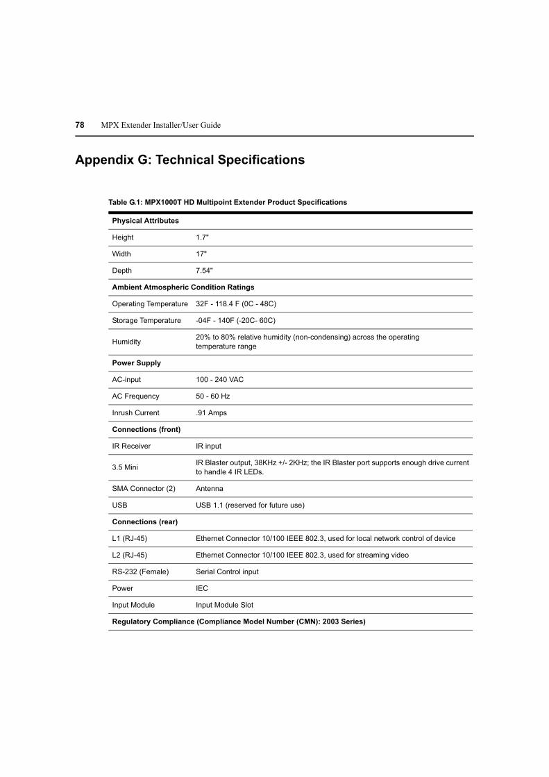
78 MPX Extender Installer/User Guide
Appendix G: Technical Specifications
Table G.1: MPX1000T HD Multipoint Extender Product Specifications
Physical Attributes
Height 1.7"
Width 17"
Depth 7.54"
Ambient Atmospheric Condition Ratings
Operating Temperature 32F - 118.4 F (0C - 48C)
Storage Temperature -04F - 140F (-20C- 60C)
Humidity20% to 80% relative humidity (non-condensing) across the operating
temperature range
Power Supply
AC-input 100 - 240 VAC
AC Frequency 50 - 60 Hz
Inrush Current .91 Amps
Connections (front)
IR Receiver IR input
3.5 MiniIR Blaster output, 38KHz +/- 2KHz; the IR Blaster port supports enough drive current
to handle 4 IR LEDs.
SMA Connector (2) Antenna
USB USB 1.1 (reserved for future use)
Connections (rear)
L1 (RJ-45) Ethernet Connector 10/100 IEEE 802.3, used for local network control of device
L2 (RJ-45) Ethernet Connector 10/100 IEEE 802.3, used for streaming video
RS-232 (Female) Serial Control input
Power IEC
Input Module Input Module Slot
Regulatory Compliance (Compliance Model Number (CMN): 2003 Series)

Appendices 79
Standards FCC Class B, UL, cUL, RoHS, CE, ICES-003, WEEE
Supported Radio Bands
UNII 1: (4 channels) 5.15-5.25 GHz
UNII 3: (4 channels) 5.725 to 5.825 GHz
ISM (11 channels) 2.412 to 2.462 GHz (supported in USA only)
Table G.2: MPX1000R HD Multipoint Extender Product Specifications
Physical Attributes
Height 1.7"
Width 12.75"
Depth 7.54"
Ambient Atmospheric Condition Ratings
Operating Temperature 32F - 118.4 F (0C - 48C)
Storage Temperature -04F - 140F (-20C- 60C)
Humidity20% to 80% relative humidity (non-condensing) across the operating
temperature range
Power Supply
AC-input 100 - 240 VAC
AC Frequency 50 - 60 Hz
Inrush Current .91 Amps
Connections (front)
IR Receiver IR input
3.5 MiniIR Blaster output, 38KHz +/- 2KHz; the IR Blaster port supports enough drive current
to handle 4 IR LEDs.
SMA Connector (2) Antenna
USB USB 1.1 (Not Used at this time)
Connections (rear)
L1 (RJ-45) Ethernet Connector 10/100 IEEE 802.3, used for local network control of device
L2 (RJ-45) Ethernet Connector 10/100 IEEE 802.3, used for streaming video
Table G.1: MPX1000T HD Multipoint Extender Product Specifications (Continued)

80 MPX Extender Installer/User Guide
RS-232 (Female) Serial Control input
Power IEC
Input Module Input Module Slot
Regulatory Compliance (Compliance Model Number (CMN): 2003 Series)
Standards FCC Class B, UL, cUL, RoHS, CE, ICES-003, WEEE
Supported Radio Bands
UNII 1: (4 channels) 5.15-5.25 GHz
UNII 3: (4 channels) 5.725 to 5.825 GHz
ISM (11 channels) 2.412 to 2.462 GHz (supported in USA only)
Table G.3: MPX1000T HDMI Input Module Product Specifications
Connections
RCA Female (2) Unbalanced Audio Input
HDMI Digital Audio/Video Control
Video
HDMI A/V input Port
Supports the following HDMI and DVI-D resolutions:
Computer resolutions: (at 30 frames per second)
- 640 x 480 @ 60Hz
- 800 x 600 @ 60Hz
- 1280x720 @ 60Hz
- 1280x768 @ 60Hz*
- 1360x768 @ 60Hz*
* Support for these resolutions may require a hardware upgrade. Contact Avocent
technical support for details.
SD video resolutions: (at 30 frames per second)
- 480i @ 60Hz
- 480p @ 60Hz
- 576i @ 50Hz
- 576p @ 50Hz
HD video resolutions: (at 30 frames per second)
- 720p @ 50/60Hz
- 1080i @ 50/60Hz
Audio
Table G.2: MPX1000R HD Multipoint Extender Product Specifications (Continued)

Appendices 81
Line Audio Inputs Less than or equal to 10K Ohm with 0-36db of headroom (Sensitivity)
Frequency ResponseThe Analog audio frequency response: 20Hz-20Khz with a 3dB per octave roll-off
beginning at 14 kHz
Regulatory Compliance (Compliance Model Number (CMN): 2003 Series)
Standards FCC Class B, UL, cUL, RoHS, CE, ICES-003, WEEE
Table G.4: MPX1000R HDMI Output Module Product Specifications
Connections
RCA Female (2) Unbalanced Audio Input
HDMI Digital Audio/Video Control
Video
Video Gain Unity ±1DB
HDMI A/V Output Port
Supports the following HDMI and DVI-D resolutions:
Computer resolutions: (at 30 frames per second)
- 640 x 480 @ 60Hz
- 800 x 600 @ 60Hz
- 1280x720 @ 60Hz
- 1280x768 @ 60Hz*
- 1360x768 @ 60Hz*
* Support for these resolutions may require a hardware upgrade. Contact Avocent
technical support for details.
SD video resolutions: (at 30 frames per second)
- 480i @ 60Hz
- 480p @ 60Hz
- 576i @ 50Hz
- 576p @ 50Hz
HD video resolutions: (at 30 frames per second)
- 720p @ 50/60Hz
- 1080i @ 50/60Hz
Audio
Audio Gain Unity
Table G.3: MPX1000T HDMI Input Module Product Specifications (Continued)

82 MPX Extender Installer/User Guide
Line Audio Outputs Line audio outputs should be 600 Ohm with a internal resistance of about 150 Ohm
Frequency ResponseThe Analog audio frequency response: 20Hz-20Khz with a 3dB per octave roll-off
beginning at 14 kHz
Regulatory Compliance (Compliance Model Number (CMN): 2003 Series)
Standards FCC Class B, UL, cUL, RoHS, CE, ICES-003, WEEE
Table G.5: MPX1000T HD15 (VGA) Input Module Product Specifications
Connections
RCA Female (2) Unbalanced Audio Input
HD15 Analog Video Input
Video
HD15 A/V Input Port
Supports the following resolutions:
Computer (VGA) resolutions: (at 30 frames per second)
- 640 x 480 @ 60Hz
- 800 x 600 @ 60Hz
- 1280x720 @ 60Hz
- 1280x768 @ 60Hz*
- 1360x768 @ 60Hz*
* Support for these resolutions may require a hardware upgrade. Contact Avocent
technical support for details.
SD video (component) resolutions: (at 30 frames per second)
- 480i @ 60Hz
- 480p @ 60Hz
- 576i @ 50Hz
- 576p @ 50Hz
HD video (component) resolutions: (at 30 frames per second)
- 720p @ 50/60Hz
- 1080i @ 50/60Hz
Audio
Line Audio Inputs Less than or equal to 10K Ohm with 0-36db of headroom (Sensitivity)
Frequency ResponseThe Analog audio frequency response: 20Hz-20Khz with a 3dB per octave roll-off
beginning at 14 kHz
Regulatory Compliance (Compliance Model Number (CMN): 2003 Series)
Standards FCC Class B, UL, cUL, RoHS, CE, ICES-003, WEEE
Table G.4: MPX1000R HDMI Output Module Product Specifications (Continued)

Table G.6: MPX1000R HD15 (VGA) Output Module Product Specifications
RCA Female (2) Unbalanced Audio Input
HD15 Analog Video Output
Video
Video Gain Unity ±1DB
HD15 A/V Output Port
Supports the following VGA video resolutions:
Computer (VGA) resolutions: (at 30 frames per second)
- 640 x 480 @ 60Hz
- 800 x 600 @ 60Hz
- 1280x720 @ 60Hz
- 1280x768 @ 60Hz
- 1360x768 @ 60Hz
SD video (VGA) resolutions: (at 30 frames per second)
- 480i @ 60Hz
- 480p @ 60Hz
- 576i @ 50Hz
- 576p @ 50Hz
HD video (VGA) resolutions: (at 30 frames per second)
- 720p @ 50/60Hz
- 1080i @ 50/60Hz
Audio
Audio Gain Unity
Line Audio Outputs Line audio outputs should be 600 Ohm with a internal resistance of about 150 Ohm
Frequency ResponseThe Analog audio frequency response: 20Hz-20Khz with a 3dB per octave roll-off
beginning at 14 kHz
Regulatory Compliance (Compliance Model Number (CMN): 2003 Series)
Standards FCC Class B, UL, cUL, RoHS, CE, ICES-003, WEEE
Appendices 83
Table G.7: MPX1500R HD Multipoint Extender Product Specifications
Physical Attributes
Height 1.0"
Width 6.92"
Depth 4.55"
Ambient Atmospheric Condition Ratings

84 MPX Extender Installer/User Guide
Operating Temperature 32F - 118.4 F (0C - 48C)
Storage Temperature -04F - 140F (-20C- 60C)
Humidity20% to 80% relative humidity (non-condensing) across the operating
temperature range
AltitudeAltitude 10,000 ft across the operating temperature range, 35,000 ft across storage
temperature range
Shock 140G - 3 axis
Power Supply
AC-input 100 - 240 VAC
AC Frequency 50 - 60 Hz
Inrush Current 14.2 Amps (AC/DC adapter)
Connections (front)
2.5mm mini-jack IR input (optional IR-RX adapter with 1m cable is required)
3.5mm mini-jackIR blaster output, 38KHz +/- 2KHz; the IR blaster port supports enough drive current
to handle 4 IR LEDs
RP-SMA Connector (2) Antenna connectors
USB USB 1.1 (not used at this time)
Connections (rear)
Power DC barrel connector
Serial (RJ-45)Dual serial port for control of attached display devices. Requires optional DB9-DUAL
female serial cable.
LAN (RJ-45) Ethernet connector 10/100 IEEE 802.3, used for streaming video and web access
DVI-I AV output port that supports a wide range of digital and analog video modes
RCA jacks (2) Left and right jacks for unbalanced analog audio.
S/PDIF Digital audio output. Operation of this port may require a firmware upgrade.
Video
Video Gain Unity ±1DB
Table G.7: MPX1500R HD Multipoint Extender Product Specifications (Continued)

Appendices 85
Video Resolutions
(VGA)
Supports the following VGA video resolutions:
Computer (VGA) resolutions: (at 30 frames per second)
- 640 x 480 @ 60Hz
- 800 x 600 @ 60Hz
- 1280x720 @ 60Hz
- 1280x768 @ 60Hz*
- 1360x768 @ 60Hz*
* Support for these resolutions may require a hardware upgrade. Contact Avocent
technical support for details.
SD video (VGA) resolutions: (at 30 frames per second)
- 480i @ 60Hz
- 480p @ 60Hz
- 576i @ 50Hz
- 576p @ 50Hz
HD video (VGA) resolutions: (at 30 frames per second)
- 720p @ 50/60Hz
- 1080i @ 50/60Hz
Video Resolutions
(component video)
SD video (component) resolutions: (at 30 frames per second)
- 480i @ 60Hz
- 480p @ 60Hz
- 576i @ 50Hz
- 576p @ 50Hz
HD video (component) resolutions: (at 30 frames per second)
- 720p @ 50/60Hz
- 1080i @ 50/60Hz
Table G.7: MPX1500R HD Multipoint Extender Product Specifications (Continued)

86 MPX Extender Installer/User Guide
Video Resolutions
(HDMI)
Supports the following HDMI and DVI-D resolutions:
Computer resolutions: (at 30 frames per second)
- 640 x 480 @ 60Hz
- 800 x 600 @ 60Hz
- 1280x720 @ 60Hz
- 1280x768 @ 60Hz
- 1360x768 @ 60Hz
SD video resolutions: (at 30 frames per second)
- 480i @ 60Hz
- 480p @ 60Hz
- 576i @ 50Hz
- 576p @ 50Hz
HD video resolutions: (at 30 frames per second)
- 720p @ 50/60Hz
- 1080i @ 50/60Hz
Audio
Sensitivity Line audio inputs less than or equal to 10K Ohm with 0-36db of headroom
Frequency responseAnalog audio frequency response: 20Hz-20Khz with a 3dB per octave roll-off
beginning at 14 kHz
Regulatory Compliance (Compliance Model Number (CMN): 2003 Series)
Standards FCC Class B, UL, cUL, RoHS, CE, ICES-003, WEEE
Supported Radio Bands
UNII 1: (4 channels) 5.15-5.25 GHz
UNII 3: (4 channels) 5.725 to 5.825 GHz
ISM (11 channels) 2.412 to 2.462 GHz (supported in USA only)
Table G.7: MPX1500R HD Multipoint Extender Product Specifications (Continued)

Appendices 87
Appendix H: Displaying Firmware and Hardware Versions
The Firmware and Hardware Versions page is used to display the firmware and hardware version
numbers. This page is the same for transmitters or receivers.
To display version information:
1. Select Version Information from the Transmitter Menu or Receiver Menu, located on the left
side of the web page.
2. Check the version numbers and decide whether you want to proceed with a Flash update.
The Firmware and Hardware Versions page displays the following information:
Table H.1: Firmware and Hardware Versions Page Information
Field Description
Device Name Transmitter or Receiver Name
MAC Address L1 MAC address (control LAN) of the transmitter or receiver, also printed on an
external label on the unit
Main Application
Firmware Version
The version number of the main application firmware
Front Panel
Firmware Version
The version number of the front panel interface application firmware
Bootloader
Firmware Version
The version number of the bootloader firmware
Main Board
Hardware Version
The version number of the main board hardware

88 MPX Extender Installer/User Guide
Appendix I: Upgrading MPX Firmware
NOTE: You must have access to a TFTP server to perform the Flash update process.
The Flash Update page is used to download and install new firmware. All of the steps in this
process and the web pages are the same for a transmitter and receivers. The Flash update process
goes through several different stages. The web interface displays a different page depending on its
current state.
It is possible to upgrade the firmware of an MPX receiver across the wireless media extension
network. Although the update process can be initiated during an active media session, it is
recommended to disconnect the source device from the MPX transmitter prior to starting the
upgrade process. This will allow more bandwidth for transmission of the upgrade file, thus
reducing the overall time to perform the upgrade.
The upgrade will complete in the shortest possible time when initiated directly via the physical
control LAN (L1) port of an MPX receiver.
To start a Flash update:
1. Select Flash Upgrade from the Transmitter Menu or Receiver Menu, located on the left side of
the web page.
2. Type the IP address of the TFTP server from which you are downloading the new Flash image.
By default, this will be the address of the server making the request.
NOTE: TFTP is used to download the image file; to do this it must be properly configured on the server.
3. Type the full path name of the image file to be downloaded.
NOTE: You may need to specify the file name relative to the server’s TFTP root directory.
4. Click Apply. If you provided valid parameters, the Flash update process starts downloading the
image file.
NOTE: Do not turn off the unit while the download is in progress.
Downloading the update
The image file is downloaded via TFTP. The web page indicates that the download is in progress.
This page updates every three seconds. Press Cancel, if necessary, to return to the main Flash
Update page.
Installing the update
After the image file has been downloaded, the web page shows version numbers for the main
firmware application and the boot firmware. For each, the current version is displayed as well as
the new version provided by the image file.

Appendices 89
To install the Flash update:
1. Check the version numbers and decide whether you want to proceed with the Flash update.
2. Click Install Image to start the Flash update process, or click Cancel to return to the main Flash
Update page.
NOTE: Do not turn off the unit while the download is in progress.

90 MPX Extender Installer/User Guide
Flash update progress
The web page shows the update progress and a percent complete for each of the Flash update steps.
The web page updates every three seconds. Press Cancel, if necessary, to return to the main Flash
Update page. Do not turn off the unit because it may not recover.
NOTE: Flash update steps for Erase boot region and Write boot image do not occur if the current boot version
and the new boot version are the same.
To continue with the Flash update steps and progress:
1. First, the boot region in Flash memory is erased.
2. Next, the boot region on Flash memory is written. The web page is the same as the Erase boot
region state. It shows the update progress and a percent complete.
3. The main firmware application region on Flash memory is erased.
4. The web page shows the update progress and a percent complete while updating every three
seconds. Again, do not turn off while in this state. Press Cancel, if necessary, to return to the
main Flash Update page.
5. The main firmware application is written to Flash memory. The web page is the same as the
Erase application region state; it shows the update progress and a percent complete.
6. If the Flash upgrade process successfully completes, the web page indicates this and the unit
will reboot to complete the update process.
Flash update status
The receiver has five colored LEDs on the front panel that communicate the current state of the
device. The LEDs are located in the following order (left to right):
RED AMBER1 AMBER2 GREEN1 GREEN2
While the receiver is upgrading Flash memory, these lights show the current state of the Flash
update. Each LED has a specific meaning as follows:
• GREEN2 - Flashes to indicate that the upgrade is in progress and that it has not failed. While
this LED is flashing, one or more of the GREEN1, AMBER2 or AMBER1 LEDs will also be a
solid color or blinking to indicate the progress of the Flash upgrade.
• GREEN1 - Blinks while file download is in progress. On solid after download has completed.
• AMBER2 - Blinks while erase or Flash of the boot image is in progress. On solid after boot
image Flash has successfully completed.
• AMBER1 - Blinks while erase or Flash of the application image is in progress. On solid after
application image Flash has successfully completed.
• RED - Flashes to indicate that an error has occurred. All other LEDs are off while this LED
is flashing.
NOTE: The difference between flashing and blinking of the LEDs is that flashing occurs at four flashes per
second, whereas blinking occurs at a slower rate of 1.5 seconds per blink.

Appendices 91
Flash update errors
A Flash update error may occur at any state. An error message is displayed. Click Restart to
try again.

92 MPX Extender Installer/User Guide
Appendix J: Supported ISO Country Codes
Table J.1: MPX Extender Supported ISO Country Codes
Country ISO Code
North America
United States US
Canada CA
Europe
Austria AT
Belgium BE
Cyprus CY
Czech Republic CZ
Denmark DK
Estonia EE
Finland FI
France FR
Germany DE
Greece GR
Hungary HU
Ireland IE
Italy IT
Latvia LV
Lithuania LT
Luxembourg LU
Malta MT
Netherlands NL
Norway NO
Poland PL
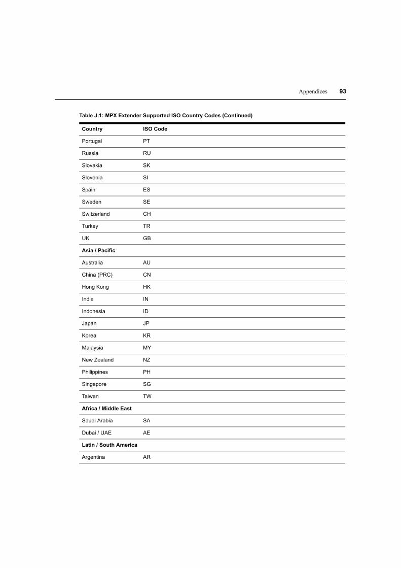
Appendices 93
Portugal PT
Russia RU
Slovakia SK
Slovenia SI
Spain ES
Sweden SE
Switzerland CH
Turkey TR
UK GB
Asia / Pacific
Australia AU
China (PRC) CN
Hong Kong HK
India IN
Indonesia ID
Japan JP
Korea KR
Malaysia MY
New Zealand NZ
Philippines PH
Singapore SG
Taiwan TW
Africa / Middle East
Saudi Arabia SA
Dubai / UAE AE
Latin / South America
Argentina AR
Table J.1: MPX Extender Supported ISO Country Codes (Continued)
Country ISO Code

94 MPX Extender Installer/User Guide
Brazil BR
Mexico MX
Table J.1: MPX Extender Supported ISO Country Codes (Continued)
Country ISO Code

Appendices 95
Appendix K: Kit Contents
Table K.1: MPX1000 Transmitter Kit Contents
Part Number Description
MPX1000T MPX transmitter
IRB-100 Dual IR blaster
038-0208-5 2 omni-directional antennas
570-1390-501 2 rack mount brackets
Varies by region Line cord
590-645-501x Quick Installation Guide
Table K.2: MPX1000 Receiver Kit Contents
Part Number Description
MPX1000R MPX receiver
038-0208-5 2 omni-directional antennas
Varies by region Line cord
590-645-501x Quick Installation Guide (x = revision)
Table K.3: MPX1000 Receiver HDMI Media Module Kit Contents
Part Number Description
MPX1000MR-HDMI Receiver media module
DVI-HDMI DVI-HDMI converter
Table K.4:
Part Number Description
MPX1000MT-HDMI Transmitter media module
DVI-HDMI DVI-HDMI converter
MPX1000 Transmitter HDMI Media Module Kit Contents

96 MPX Extender Installer/User Guide
Table K.5:
Part Number Description
MPX1000MR-HD15 Receiver media module
MPX1000 Receiver VGA Media Module Kit Contents
Table K.6:
Part Number Description
MPX1000MT-HD15 Transmitter media module
MPX1000 Transmitter VGA Media Module Kit Contents
Table K.7: MPX1500 Receiver Kit Contents
Part Number Description
MPX1500R MPX receiver
038-0208-5 2 omni-directional antennas
Varies by region Power supply and AC line cord
590-506-501x Quick Installation Guide

97
A
A/V signals 1
Accessories 7
Active EDID 3
Audio Considerations 67
B
Benefits, MPX1000 Extender product 2
Bound receiver 3
C
Configuration, transmitter 22
Configure network settings 6
Control LAN 3
D
Default EDID 4
Definitions 3
Display device 4
Display modes, front panel 53
E
EDID handling 8
Extender 4
Extension Network 4
F
Features, MPX1000 HD Multipoint Extender 1
Front panel display 53
Front panel, receiver 14, 16
Front panel, transmitter 11
H
HDCP 4, 9
I
Input media module 4
Installing, media module 21
L
Latency 2
Lip sync 2
M
Main menu, front panel display 55
Media module 4, 15, 21
Media module, HD15 19
Media module, HDMI 18
MPX Extender 4
O
Output media module 5
P
Password 34
Placement, Transmitter and Receiver 27
Primary Display Device 5
Primary EDID 5
Primary receiver 5, 8
R
Rear panel, receiver 15, 17
Rear panel, transmitter 12
Reboot system 52
Receiver 5, 13
Reset defaults 52
S
Safety considerations, rack mount 10
Source device 5
INDEX
98 MPX Extender Installer/User Guide
Status 49
System configuration diagram 3
T
Transmitter 5, 11
Transmitter Number 5
U
Universal A/V port 5
User interfaces 6
W
Web-based interface 6
Wired link 5
Wireless link 5

For Technical Support:
590-671-501F
www.avocent.com/support