emic/mda data sheetproducts.ecc.emea.honeywell.com/europe-historic... · 4 emic/mda data sheet...
TRANSCRIPT

EMIC/MDA Data Sheet TA201081 Issue 8, 27-Jul-2015. Applies to v2.06. 1
Data Sheet
EMIC/MDAEthernet MODBUS Metering Interface Controller
EMIC/MDA
Description
The EMIC/MDA (Ethernet Metering Interface Controller) provides an interface for up to 8, 16 or 32 energy meters. It connects to the Trend system using Ethernet, and to the meters using RS485, MODBUS. It sits on the internetwork and takes a LAN for its own use, each meter being represented by an outstation on that LAN. Data from each meter is collected using the RS485 bus and stored in the EMIC/MDA within the relevant outstation. Each meter can be chosen from a range of meters from various suppliers. It can be configured using an integral web server.
Features
▪ Versions for 8, 16, or 32 MODBUS meters ▪ A wide range of easily selectable meter definitions is available ▪ Configurable using built-in web pages ▪ Meters appear as outstations on a LAN ▪ RS485 cable provided ▪ EMIC IPTool can find EMICs’ IP addresses ▪ Can calculate cumulative kWh over defined period ▪ DHCP capability
Physical
EMIC
power supply inputEthernet to Trend System
MODBUS to meters
MODBUS LED
Power On LED
DIP switch
USB ports (not used)
LEDs not used
reset button
System OK LEDEthernet OK LED
4 off Ø4 mm
88 mm (3.46”)
77 mm (3.03”)
100 mm (3.93”)
26 mm 1.02”
19 mm
108
mm
(4.2
5”)
127
mm
(5”)
25
mm
(0
.98”
)
DIN rail clip shown on this view

2 EMIC/MDA Data Sheet TA201081 Issue 8, 27-Jul-2015. Applies to v2.06.
EMIC/MDA Data Sheet
FUNCTIONALITYThe EMIC’s functionality can be divided into can be divided into four sections: “System”, “Hardware”, “Firmware”, and “Web Pages”.
SYSTEM
The EMIC is a member of the internetwork, and its firmware simulates a LAN with each meter represented as an outstation (e.g. an IQ® Controller).
The two vCNCs (virtual CNCs), one at the default address of 119, are for use within the EMIC.
Lan
EMIC
Internetwork (126)
(119)v
CNC
vCNC
vINC
vOS
vOS
vOS
vOS
vOS
vOS
vOS
Up to 32 meters represented as virtual outstations
A supervisor (e.g 963) can connect to the EMIC via a vCNC in an XTEND or IQ Controller.
Internetwork
XTEND
Lan
Supervisor
supervisormodealarmmode
IQController
Lan
EMIC
(126)
(119)v
CNC
vCNC
vINC vOS
vOS
vOS
vOS
vOS
vOS
vOS
vCNC
vINC
vINC
vCNC
vCNC
vCNC
In the above diagram, the Supervisor connects to the XTEND’s LAN using a supervisor mode vCNC. The vINCs (in XTEND, EMIC, and IQ controller) construct an internetwork. The supervisor can communicate across the internetwork to obtain the meter readings from a vOS.
A vOS can send Sensor High and Low alarms to the supervisor either through the XTEND’s vCNC in supervisor mode if the supervisor is permanently connected or through a XTEND vCNC set to alarm mode if the supervisor is not permanently connected.
The IQ3 controller is able to send Inter-Contoller Communications to the EMIC/MDA (e.g. to obtain meter readings). The IC Comms cannot be attribute comms so are limited to simple Data To and Data From comms.
It is not recommended that the EMIC vCNCs are used to connect to the system.
The diagram below shows the physical connections equivalent to the above schematic.
EMIC/MDA
Supervisor
Ethernet
IQ Controller
XTEND
Meter 1 Meter n
MODBUS (RS485)
The Supervisor, IQ controller, XTEND, and EMIC are connected to the Ethernet bus. The EMIC/MDA is connected to its meters using the MODBUS (RS485).
Note that the EMIC takes a fixed IP address by default but this may be changed to DHCP addressing (on the IP settings web page). If sending IP alarms, the destination device (e.g. supervisor) must have a fixed address.
Note: Installing this unit as part of a Building Management System can support April 2006 Part L2 Building Regulations compliance.
HArDwArE
The EMIC consists of a metal box which can be either surface mounted (using 4 off 4 mm holes) or DIN rail mounted (using the screws and clips provided with the unit).
Supply: The unit requires 24 Vdc at 300 mA via a two part two terminal connector. The configuration data is saved to disk on power fail, and a supercapacitor supports the real time clock for about 7 days.
Ethernet: The Ethernet connection to the Trend system is via an RJ45 connector. Typical connections to the Trend system are shown in the diagram above in the system section. An example is a direct connection of a PC to the EMIC using a standard Ethernet cable with a crossover adaptor.
EMIC
PC
Crossover adaptor
Standard Ethernet cable
This configuration can be used for browser access (not 963) to the EMIC’s web pages to configure the EMIC.
rS485: The RS485 (MODBUS) connection to the meters is via an RJ45 connector. This is Port 1 on the bottom edge of the unit. A 2.5 m RJ45 to MODBUS cable is supplied with the unit
The EMIC/MDA connection to the meters is by RS485 2 wire which is multidrop, and half duplex. The EMIC/MDA is the master, and the meters are slaves. There may be up to 32 meters on the bus.
Note: Only bus topology should be used (not loop or star), and any stubs should be kept short.

EMIC/MDA Data Sheet TA201081 Issue 8, 27-Jul-2015. Applies to v2.06. 3
Data Sheet EMIC/MDA
SYSTEM (continued)
......
2 wire RS485
Meter n Meter 2 Meter 1
EMIC/MDA
The meter terminals may be labelled A(+) and B(-) (or D0 and D1) respectively; these correspond to DATA+ and DATA- on the EMIC/MDA. Polarity must be observed, A to A, B to B.
0V A B 0V A B 0V A B
0V DATA+
RJ45 Port 1
EMIC/MDA
DATA-
423
0V A B
Red
Ora
nge
Red
Orange
meter meter meter meter
terminatorterminator
For long runs (>30 m) the bus should be terminated with a 150 ohm resistor across the single pair of lines at each end of the bus only (not at any devices in the middle) for shorter runs terminators should not be used.
The maximum length including stubs at 9600 baud using 26 AWG twisted pair cable is 1000 m.
Some meters may require line polarisation. This requires to 0V line to be connected to each device and a pull down to 0V resistor on A line, with a pull up to 5V resistor on the B line. These resistors should be between 450 to 650 ohms. Use of line polarisation reduces the number of meters that can be connected.
0V A B 0V A B 0V A B
0V DATA+
RJ45 Port 1
EMIC/MDA
DATA-
423
0V A B
Red
Ora
ng
e
Re
d
Orange
5V
450 to
650 ohms
450 to
650 ohms
Bla
ck
Black
meter meter meter meter
Indicators: Various indicators are provided giving feedback on the operational status of the EMIC.
Indicator Colour FunctionPower Green ON when power is appliedSystem Ready Green ON when the EMIC is readyEthernet LAN Green ON indicates a good Ethernet
connection.M-Bus P1 Green/Yellow Flashing indicates activity on
the M-Bus (green - incoming, yellow - outgoing).
P2 to P4 (Not used)
DIP switch: Must be set correctly (all off)
USB ports: 2 off USB ports (not used).
Mini-USB port: (not used)
reset button: Resets the unit. This can be used to restart the unit if the software reboot fails.
FIrMwArE
Meters
The EMIC/MDA will communicate as a MODBUS master with either 8, 16, or 32 meters depending on the variant. Each meter appears as a virtual outstation (vOS).
There are fifteen meter definitions stored in the EMIC/MDA and each virtual outstation can be set to one of those types. The types of meter are:
Manufacturer MeterTrend EM-SB3/0/485/DC, EM-SB3/0/485/CT,
EM-MPO/Star3 (including/Star3DIN),EM-MPO/Sirio, EM-MPO/350(e),EM-MPO/400(e)
Honeywell EEM230-D-MO, EEM230-D-MO-MID,EEM400C-D-MO, EEM400C-D-MO-MID,EEM400-D-MO,EEM400-D-MO-MID
IME Nemo 96, Nemo 72, Nemo D4-LCarlo Gavazzi EM24-DIN, EM-21Socomec Diris A40/A41, Diris A20Autometers IC970 v4/v5 and v6Schneider PM710, PM750, PM800
Note: EM-MPO/350(e), and EM-MPO/400(e) can be used for Northern Design Cube 350 or Cube 400.
Up to 25 meter points can be transferred from each meter to the vOS where they will appear as sensor module values. The points for each type of meter are shown in the tables on the following two pages In addition Sensor 26 can be used to display the Cumulative kWh calculated by the calculator feature; the calculations must be set up in the Calculator (see later) and its label set up manually.
Each meter should be set up with a unique MODBUS slave address, and the MODBUS communication parameters should match those set up in the EMIC/MDA (see ‘Comms Settings’ on page 14).
Modules
Modules that apply to the whole EMIC
Virtual CNCs Outstation address of each of the 2 virtual CNCs.
UDP Group UDP Group numberNum. OSs/ Lan Number
Create or delete outstations and set LAN number.
IC Comms The EMIC is not able to initiate IC Comms but it will respond to Data To and Data From IC Comms initiated elsewhere (but not to any attribute comms - Max, Min, Sum, Average, Global to, or any label matching item selection).
Modules that apply to the individual OutstationThe following tables show the parameters for the configuration modules in each vOS. Parameters shown * are shared between all outstations so a change to one will change all.
Note: The text communication codes in the following tables are fully described in the IQ3 Configuration Manual (TE200768).

4 EMIC/MDA Data Sheet TA201081 Issue 8, 27-Jul-2015. Applies to v2.06.
EMIC/MDA Data Sheet
Modules that apply to the individual Outstation (continued)
Time: Text comms code (T), 1 off. The EMIC will set the time and date of all its vOSs on receipt of a timemaster synchronisation message.
Parameter Text Comms Code r/wHour *H R/WMinute *N R/WSecond *C RDay *D R/WMonth *M R/WYear *Y R/WWeekday *W R
Address module: Text comms code (R), 1 off.
Parameter Text Comms Code r/wLocal Lan L RLocal Node N RAlarm node A R/WAlarm Lan R R/WIdentifier D R/WMachine GUID *O R/WHuman GUID *$ R/WVersion C RDestination IP address -Destination Port -
Network: Text comms code (n), 1 off.
Parameter Text Comms Code r/wHost name *$ RType (set to 4, Ethernet IP) *Y RIP Address *I RAuto address (set to 1 for DHCP)
*P R
Default Gateway -Subnet mask -
Sensor: Text comms code (S), 100 off. Each meter parameter is monitored by a sensor module and there are up to 20 such sensors plus 20 sensors for displaying calculated energy usage at defined time periods. The remainder are not displayed on the sensors web page.
Parameter Text Comms Code r/wLabel L RUnits N RValue A R/WHigh alarm limit R R/WLow alarm limit D R/WAlarm status bits O R/WAlarm enable bits $ R/WAlarm Ack Bits C R
Plots: Text comms code (P), 99 off. They are precision and compact synchronised plots, but not IQ3 type triggered or periodic plots. There can be up to 1024 plots per EMIC, each plot may have up to 1000 values.
Parameter Sub parameter Text Comms Code r/wLabel L RSource sensor S R/WPeriod P R/WMaximum number of points N RCurrent number of points R RTotal points so far C RBBUF threshold n R/WPoints recorded since last BBUF r RPoints count at last BBUF l RTime at last BBUF b RPlot point B
Point value V RTotal point count E RSeconds since last point
O R
Point time T R
User: Text comms code (U), 6 off.
Parameter Text Comms Code r/wLevel L R/WPin number P R/W
Meter Points
Trend Meters
Sensor Point (EMIC Label) UnitsEM-SB3/0/485/CT
MODBUS Data Address Meter Label
1 Energy Total Trf 1 kWh 28-29 Energy Total Trf 12 Energy Partial Trf 1 kWh 30-31 Energy Partial Trf 13 Effective active Power of all phases kW 51 Effective active Power of all phases4 Effective reactive Power of all phases kVar 52 Effective reactive Power of all phases5 Effective active Power of Phase 1 kW 38 Effective active Power of Phase 16 Effective active Power of Phase 2 kW 43 Effective active Power of Phase 27 Effective active Power of Phase 3 kW 48 Effective active Power of Phase 38 Effective reactive Power of Phase 1 kVar 39 Effective reactive Power of Phase 19 Effective reactive Power of Phase 2 kVar 44 Effective reactive Power of Phase 210 Effective reactive Power of Phase 3 kVar 49 Effective reactive Power of Phase 311 Effective Current Ph1 A 37 Effective Current Ph112 Effective Current Ph2 A 42 Effective Current Ph213 Effective Current Ph3 A 47 Effective Current Ph314 Effective Voltage Ph1 V 36 Effective Voltage Ph115 Effective Voltage Ph2 V 41 Effective Voltage Ph216 Effective Voltage Ph3 V 46 Effective Voltage Ph317 Current Transformer Ratio 23 Not used

EMIC/MDA Data Sheet TA201081 Issue 8, 27-Jul-2015. Applies to v2.06. 5
Data Sheet EMIC/MDA
Trend Meters (continued)Note: When using CT ratio 1/1 on Trend EM-SB3/0/485/CT the readings from the EMIC will be 1/10 actual value. This can be corrected using the EMICs calculator function. The calculator must have 1 calculation for each register as below:
Source = OSnn S11, first operation = A/B (where B = fixed value of 0.1), Destination = OSnn S21
Source = OSnn S12, first operation = A/B (where B = fixed value of 0.1), Destination = OSnn S22
Source = OSnn S13, first operation = A/B (where B = fixed value of 0.1), Destination = OSnn S23
Sensor Point (EMIC Label) UnitsEM-SB3/0/485/DC
MODBUS Data Address Meter Label1 Energy Total Trf 1 kWh 28-29 Energy Total Trf 12 Energy Partial Trf 1 kWh 30-31 Energy Partial Trf 13 Energy Total Trf 2 kWh 32-33 Energy Total Trf 24 Energy Partial Trf 2 kWh 33-35 Energy Partial Trf 25 Effective active Power of all phases kW 51 Effective active Power of all phases6 Effective reactive Power of all phases kVar 52 Effective reactive Power of all phases7 Effective active Power of Phase 1 kW 38 Effective active Power of Phase 18 Effective active Power of Phase 2 kW 43 Effective active Power of Phase 29 Effective active Power of Phase 3 kW 48 Effective active Power of Phase 310 Effective reactive Power of Phase 1 kVar 39 Effective reactive Power of Phase 111 Effective reactive Power of Phase 2 kVar 44 Effective reactive Power of Phase 212 Effective reactive Power of Phase 3 kVar 49 Effective reactive Power of Phase 313 Effective Current Ph1 A 37 Effective Current Ph114 Effective Current Ph2 A 42 Effective Current Ph215 Effective Current Ph3 A 47 Effective Current Ph316 Effective Voltage Ph1 V 36 Effective Voltage Ph117 Effective Voltage Ph2 V 41 Effective Voltage Ph218 Effective Voltage Ph3 V 46 Effective Voltage Ph3
Sensor Point (EMIC Label) UnitsEM-MPO/STAr, STAr/DIN and EM-MPO/SIrO
MODBUS Data Address Meter Label1 Total Active Energy kWh 0021 Total active energy counter 2 Total Reactive
Energy kVArh 0025 Total reactive energy counter
3 Apparent Energy kVAh 0097 Apparent energy counter 4 Total Active Power kW 0005 Total active power 5 Total Reactive Power kVAr 0007 Total reactive power 6 Total Apparent Power kVA 0009 Total apparent power 7 Active Power L1 kW 0041 Active Power L1 8 Active Power L2 kW 0043 Active Power L2 9 Active Power L3 kW 0045 Active Power L3 10 Current L1 A 0035 Current L1 11 Current L2 A 0037 Current L2 12 Current L3 A 0039 Current L3 13 Total Power Factor pf 0011 Total power factor 14 Reactive Power L1 kVAr 0049 Reactive power L1 measured 15 Reactive Power L2 kVAr 0051 Reactive power L2 measured 16 Reactive Power L3 kVAr 0053 Reactive power L3 measured 17 Apparent Power L1 kVA 0055 Apparent power L1 18 Apparent Power L2 kVA 0057 Apparent power L2 19 Apparent Power L3 kVA 0059 Apparent power L3 20 Voltage L1 V V 0029 Voltage L1 21 Voltage L2 V V 0031 Voltage L2 22 Voltage L3 V V 0033 Voltage L3

6 EMIC/MDA Data Sheet TA201081 Issue 8, 27-Jul-2015. Applies to v2.06.
EMIC/MDA Data Sheet
Trend Meters (continued)
Sensor Point (EMIC Label) UnitsEM/MPO/350 (Cube 350) or EM/MPO/400 (Cube 4000)
MODBUS Data Address Meter Label1 Total Active Energy kWh 7680 & 7681 kWh High Word & Low Word2 Total Reactive Energy kVArh 7684 & 7685 kvarh High Word & Low Word 3 Apparent Energy kVAh 7682 & 7683 kVAh High Word & Low Word 4 Total Active Power kW 7705 System kW 5 Total Reactive Power kVAr 7713 System kvar 6 Total Apparent Power kVA 7709 System kVA 7 Active Power L1 kW 7702 Phase 1 kW 8 Active Power L2 kW 7703 Phase 2 kW 9 Active Power L3 kW 7704 Phase 3 kW 10 Current L1 A 7688 Phase 1 Amps 11 Current L2 A 7689 Phase 2 Amps 12 Current L3 A 7690 Phase 3 Amps 13 Total Power Factor pf 7701 System PF 14 Reactive Power L1 kVAr 7710 Phase 1 kvar 15 Reactive Power L2 kVAr 7711 Phase 2 kvar 16 Reactive Power L3 kVAr 7712 Phase 3 kvar 17 Apparent Power L1 kVA 7706 Phase 1 kVA 18 Apparent Power L2 kVA 7707 Phase 2 kVA 19 Apparent Power L3 kVA 7708 Phase 3 kVA 20 Voltage L1 V 7691 Phase 1 Volts 21 Voltage L2 V 7692 Phase 2 Volts 22 Voltage L3 V 7693 Phase 3 Volts 23 L1-L2 Voltage V 7694 Ph1-Ph2 Volts 24 L2-L3 Voltage V 7695 Ph2-Ph3 Volts 25 L3-L1 Voltage V 7696 Ph3-Ph1 Volts
Honeywell Meters
Sensor Point (EMIC Label) UnitsEEM400-D-MO and EEM400-D-MO-MID
MODBUS Data Address Meter Label1 Energy Total Trf 1 kWh 28-29 Energy Total Trf 12 Energy Partial Trf 1 kWh 30-31 Energy Partial Trf 13 Energy Total Trf 2 kWh 32-33 Energy Total Trf 24 Energy Partial Trf 2 kWh 33-35 Energy Partial Trf 25 Effective active Power of all phases kW 51 Effective active Power of all phases6 Effective reactive Power of all phases kVar 52 Effective reactive Power of all phases7 Effective active Power of Phase 1 kW 38 Effective active Power of Phase 18 Effective active Power of Phase 2 kW 43 Effective active Power of Phase 29 Effective active Power of Phase 3 kW 48 Effective active Power of Phase 310 Effective reactive Power of Phase 1 kVar 39 Effective reactive Power of Phase 111 Effective reactive Power of Phase 2 kVar 44 Effective reactive Power of Phase 212 Effective reactive Power of Phase 3 kVar 49 Effective reactive Power of Phase 313 Effective Current Ph1 A 37 Effective Current Ph114 Effective Current Ph2 A 42 Effective Current Ph215 Effective Current Ph3 A 47 Effective Current Ph316 Effective Voltage Ph1 V 36 Effective Voltage Ph117 Effective Voltage Ph2 V 41 Effective Voltage Ph218 Effective Voltage Ph3 V 46 Effective Voltage Ph320 Current Tariff 27 Current Tariff

EMIC/MDA Data Sheet TA201081 Issue 8, 27-Jul-2015. Applies to v2.06. 7
Data Sheet EMIC/MDA
Honeywell Meters (continued)
Sensor Point (EMIC Label) UnitsEEM400C-D-MO and EEM400C-D-MO-MID
MODBUS Data Address Meter Label1 Energy Total Trf 1 kWh 28-29 Energy Total Trf 12 Energy Partial Trf 1 kWh 30-31 Energy Partial Trf 13 Effective active Power of all phases kW 51 Effective active Power of all phases4 Effective reactive Power of all phases kVar 52 Effective reactive Power of all phases5 Effective active Power of Phase 1 kW 38 Effective active Power of Phase 16 Effective active Power of Phase 2 kW 43 Effective active Power of Phase 27 Effective active Power of Phase 3 kW 48 Effective active Power of Phase 38 Effective reactive Power of Phase 1 kVar 39 Effective reactive Power of Phase 19 Effective reactive Power of Phase 2 kVar 44 Effective reactive Power of Phase 210 Effective reactive Power of Phase 3 kVar 49 Effective reactive Power of Phase 311 Effective Current Ph1 A 37 Effective Current Ph112 Effective Current Ph2 A 42 Effective Current Ph213 Effective Current Ph3 A 47 Effective Current Ph314 Effective Voltage Ph1 V 36 Effective Voltage Ph115 Effective Voltage Ph2 V 41 Effective Voltage Ph216 Effective Voltage Ph3 V 46 Effective Voltage Ph317 Current Transformer Ratio 26 Transformer Ratio
Sensor Point (EMIC Label) UnitsEEM230-D-MO and EEM230-D-MO-MID
MODBUS Data Address Meter Label1 Energy Total Trf.1 kWh 28-29 Energy Total Trf.12 Energy Partial Trf.1 kWh 30-31 Energy Partial Trf.13 Power kW 38 Power4 Reactive Power total kVar 39 Reactive Power total5 Current A 37 Current6 Voltage V 36 Voltage7 cos phi 40 cos phi
IME Meters
Sensor Point (EMIC Label) UnitsNemo 96HD
MODBUS Data Address Meter Label1 Total Active Energy kWh 0x325 3-phase : positive active energy2 Total Reactive Energy kVArh 0x343 3-phase : positive reactive energy3 Total Active Power kW 0x1014 3-phase : active power4 Total Reactive Power kVAr 0x1016 3-phase : reactive power5 Total Apparent Power kVA 0x1018 3-phase : apparent power6 Active Power L1 kW 0x102c Phase 1 : active power7 Active Power L2 kW 0x102e Phase 2 : active power8 Active Power L3 kW 0x1030 Phase 3 : active power9 Current L1 A 0x1006 Phase 1 : current10 Current L2 A 0x1008 Phase 2 : current11 Current L3 A 0x100a Phase 3 : current12 Total Power Factor pf 0x1024 3-phase : power factor13 Reactive Power L1 kW 0x1035 Phase 1 : reactive power14 Reactive Power L2 kW 0x1037 Phase 2 : reactive power15 Reactive Power L3 kW 0x1039 Phase 3 : reactive power16 Apparent Power L1 kVA 0x103e Phase 1 : apparent power17 Apparent Power L2 kVA 0x1040 Phase 2 : apparent power18 Apparent Power L3 kVA 0x1042 Phase 3 : apparent power19 Voltage L1 V 0x1000 Phase 1 : phase voltage20 Voltage L2 V 0x1002 Phase 2 : phase voltage21 Voltage L3 V 0x1004 Phase 3 : phase voltage22 L1-L2 Voltage V Chained voltage : L1-L223 L2-L3 Voltage V Chained voltage : L2-L324 L3-L1 Voltage V Chained voltage : L3-L1

8 EMIC/MDA Data Sheet TA201081 Issue 8, 27-Jul-2015. Applies to v2.06.
EMIC/MDA Data Sheet
IME Meters (continued)
Sensor Point (EMIC Label) UnitsNemo 72-L
MODBUS Data Address Meter Label1 Total Active Energy kWh 0x325 3-phase : positive active energy2 Total Reactive Energy kVArh 0x343 3-phase : positive reactive energy3 Total Active Power kW 0x1014 3-phase : active power4 Total Reactive Power kVAr 0x1016 3-phase : reactive power5 Total Apparent Power kVA 0x1018 3-phase : apparent power6 Active Power L1 kW 0x102c Phase 1 : active power7 Active Power L2 kW 0x102e Phase 2 : active power8 Active Power L3 kW 0x1030 Phase 3 : active power9 Current L1 A 0x1006 Phase 1 : current10 Current L2 A 0x1008 Phase 2 : current11 Current L3 A 0x100a Phase 3 : current12 Total Power Factor pf 0x1024 3-phase : power factor13 Reactive Power L1 kW 0x1035 Phase 1 : reactive power14 Reactive Power L2 kW 0x1037 Phase 2 : reactive power15 Reactive Power L3 kW 0x1039 Phase 3 : reactive power16 Voltage L1 V 0x1000 Phase 1 : phase voltage17 Voltage L2 V 0x1002 Phase 2 : phase voltage18 Voltage L3 V 0x1004 Phase 3 : phase voltage19 L1-L2 Voltage V 0x100e Chained voltage : L1-L220 L2-L3 Voltage V 0x1010 Chained voltage : L2-L321 L3-L1 Voltage V 0x1012 Chained voltage : L3-L1
Sensor Point (EMIC Label) UnitsNemo D4-L
MODBUS Data Address Meter Label1 Total Active Energy kWh 0x101c 3-phase : positive active energy2 Total Active Power kW 0x1014 3-phase : active power3 Total Reactive Energy kVArh 0x1016 3-phase : reactive power4 Total Apparent Power kVA 0x1018 3-phase : apparent power5 Active Power L1 kW 0x102c Phase 1 : active power6 Active Power L2 kW 0x102e Phase 2 : active power7 Active Power L3 kW 0x1030 Phase 3 : active power8 Current L1 A 0x1006 Phase 1 : current9 Current L2 A 0x1008 Phase 2 : current10 Current L3 A 0x100a Phase 3 : current11 Total Power Factor pf 0x1024 3-phase : power factor12 Voltage L1 V 0x1000 Phase 1 : phase voltage13 Voltage L2 V 0x1002 Phase 2 : phase voltage14 Voltage L3 V 0x1004 Phase 3 : phase voltage15 L1-L2 Voltage V 0x100e Chained voltage : L1-L216 L2-L3 Voltage V 0x1010 Chained voltage : L2-L317 L3-L1 Voltage V 0x1012 Chained voltage : L3-L1

EMIC/MDA Data Sheet TA201081 Issue 8, 27-Jul-2015. Applies to v2.06. 9
Data Sheet EMIC/MDA
Autometers Meters
Sensor Point (EMIC Label) UnitsIC970
MODBUS Data Address Documentation name1 Total Active Energy kWh Total Active Energy kWh2 Total Reactive Energy kVArh Total Reactive Energy kVArh3 Apparent Energy kVAh Apparent Energy kVAh4 Total Active Power kW Total Active Power kW5 Total Reactive Power kVAr Total Reactive Power kVAr6 Total Apparent Power kVA Total Apparent Power kVA7 Active Power L1 kW Active Power L1 kW8 Active Power L2 kW Active Power L2 kW9 Active Power L3 kW Active Power L3 kW10 Current L1 A Current L1 A11 Current L2 A Current L2 A12 Current L3 a Current L3 A13 Total Power Factor pf Total Power Factor14 Reactive Power L1 kVAr Reactive Power L1 kVAr15 Reactive Power L2 kVAr Reactive Power L2 kVAr16 Reactive Power L3 kVAr Reactive Power L3 kVAr17 Apparent Power L1 kVA Apparent Power L1 kVA18 Apparent Power L2 kVA Apparent Power L2 kVA19 Apparent Power L3 kVA Apparent Power L3 kVA20 Voltage L1 V Voltage L1 V21 Voltage L2 V Voltage L2 V22 Voltage L3 V Voltage L3 V23 L1-L2 Voltage V24 L2-L3 Voltage V25 L3-L1 Voltage V
Carlo Gavazzi Meters
Sensor Point (EMIC Label) UnitsEM24-DIN EM-21
MODBUS Data Address Documentation name MODBUS Data
Address Documentation name
1 Total Active Energy kWh 300063 KWh(+) TOT 300053 KWh(+) TOT2 Total Reactive Energy kVArh 300065 Kvarh(+) TOT 300055 Kvarh(+) TOT3 Total Active Power kW 300041 W Σ 300041 W Σ4 Total Reactive Power kVAr 300045 VAR Σ 300045 VAR Σ5 Total Apparent Power kVA 300043 VA Σ 300043 VA Σ6 Active Power L1 kW 300019 W L1 300019 W L17 Active Power L2 kW 300021 W L2 300021 W L28 Active Power L3 kW 300023 W L3 300023 W L39 Current L1 A 300013 A L1 300013 A L110 Current L2 A 300015 A L2 300015 A L211 Current L3 A 300017 A L3 300017 A L312 Total Power Factor pf 300054 PF Σ 300050 PF Σ13 Reactive Power L1 kVAr 300031 VAR L1 300031 VAR L114 Reactive Power L2 kVAr 300033 VAR L2 300033 VAR L215 Reactive Power L3 kVAr 300035 VAR L3 300035 VAR L316 Apparent Power L1 kVA 300025 VA L1 300025 VA L117 Apparent Power L2 kVA 300027 VA L2 300027 VA L218 Apparent Power L3 kVA 300029 VA L3 300029 VA L319 Voltage L1 V 300001 V L1-N 300001 V L1-N20 Voltage L2 V 300003 V L2-N 300003 V L2-N21 Voltage L3 v 300005 V L3-N 300005 V L3-N22 L1-L2 Voltage V 300007 V L1-L2 300007 V L1-L223 L2-L3 Voltage V 300009 V L2-L3 300009 V L2-L324 L3-L1 Voltage V 300011 V L3-L1 300011 V L3-L1

10 EMIC/MDA Data Sheet TA201081 Issue 8, 27-Jul-2015. Applies to v2.06.
EMIC/MDA Data Sheet
Schneider Meters
Sensor Point (EMIC Label) UnitsPM710, PM750, PM800
MODBUS Data Address Meter Label1 Total Active Energy kWh Total Active Energy kWh2 Total Reactive Energy kVArh Total Reactive Energy kVArh3 Apparent Energy kVAh Apparent Energy kVAh4 Total Active Power kW Total Active Power kW5 Total Reactive Power kVAr Total Reactive Power kVAr6 Total Apparent Power kVA Total Apparent Power kVA7 Active Power L1 kW Active Power L1 kW8 Active Power L2 kW Active Power L2 kW9 Active Power L3 kW Active Power L3 kW10 Current L1 A Curent L1 A11 Current L2 A Current L2 A12 Current L3 A Current L3 A13 Total Power Factor pf Total Power Factor14 Reactive Power L1 kVAr Reactive Power L1 kVAr15 Reactive Power L2 kVAr Reactive Power L2 kVAr16 Reactive Power L3 kVAr Reactive Power L3 kVAr17 Apparent Power L1 kVA Apparent Power L1 kVA18 Apparent Power L2 kVA Apparent Power L2 kVA19 Apparent Power L3 kVA Apparent Power L3 kVA20 Voltage L1 V Voltage L1 V21 Voltage L2 V Voltage L2 V22 Voltage L3 V Voltage L3 V23 L1-L2 Voltage V L1-L2 Voltage24 L2-L3 Voltage V L2-L3 Voltage25 L3-L1 Voltage V L3-L1 Voltage
Socomec Meters
Sensor Point (EMIC Label) Units DirisA40/A41MODBUS Data Address Documentation name
1 Total Active Energy kWh 856 Active energy +2 Total Reactive Energy kVArh 858 Reactive energy +3 Apparent Energy kVAh 860 Apparent energy4 Total Active Power kW 1803 Σ active power +/-5 Total Reactive Power kVAr 1804 Σ reactive power +/-6 Total Apparent Power kVA 1805 Σ apparent power +/-7 Active Power L1 kW 798 Active power phase 1 +/-8 Active Power L2 kW 800 Active power phase 2 +/-9 Active Power L3 kW 802 Active power phase 3 +/-10 Current L1 L1 1792 Phase 1 current11 Current L2 L2 1793 Phase 2 current12 Current L3 L3 1794 Phase 3 current13 Total Power Factor pf 796 Σ power factor -: leading and +: lagging14 Reactive Power L1 kVAr 804 Reactive power phase 1 +/-15 Reactive Power L2 kVAr 806 Reactive power phase 2 +/-16 Reactive Power L3 kVAr 808 Reactive power phase 3 +/-17 Apparent Power L1 kVA 810 Apparent power phase 118 Apparent Power L2 kVA 812 Apparent power phase 219 Apparent Power L3 kVA 814 Apparent power phase 320 Voltage L1 V 1799 Phase to neutral voltage phase 121 Voltage L2 V 1800 Phase to neutral voltage phase 222 Voltage L3 V 1801 Phase to neutral voltage phase 323 L1-L2 Voltage V 1796 Phase to phase voltage U1224 L2-L3 Voltage V 1797 Phase to phase voltage U2325 L3-L1 Voltage V 1798 Phase to phase voltage U31
EMIC/MDA Data Sheet TA201081 Issue 8, 27-Jul-2015. Applies to v2.06. 11
Data Sheet EMIC/MDA
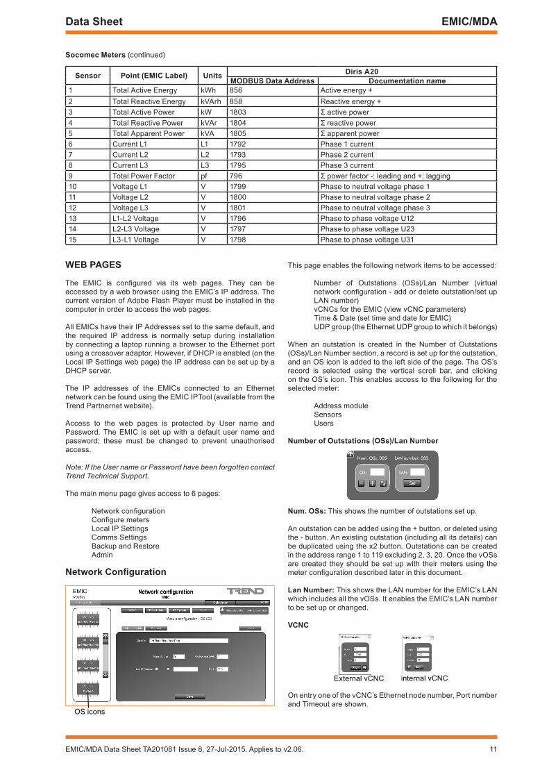
Socomec Meters (continued)
Sensor Point (EMIC Label) Units Diris A20MODBUS Data Address Documentation name
1 Total Active Energy kWh 856 Active energy +2 Total Reactive Energy kVArh 858 Reactive energy +3 Total Active Power kW 1803 Σ active power4 Total Reactive Power kVAr 1804 Σ reactive power5 Total Apparent Power kVA 1805 Σ apparent power6 Current L1 L1 1792 Phase 1 current7 Current L2 L2 1793 Phase 2 current8 Current L3 L3 1795 Phase 3 current9 Total Power Factor pf 796 Σ power factor -: leading and +: lagging10 Voltage L1 V 1799 Phase to neutral voltage phase 111 Voltage L2 V 1800 Phase to neutral voltage phase 212 Voltage L3 V 1801 Phase to neutral voltage phase 313 L1-L2 Voltage V 1796 Phase to phase voltage U1214 L2-L3 Voltage V 1797 Phase to phase voltage U2315 L3-L1 Voltage V 1798 Phase to phase voltage U31
wEB PAGES
The EMIC is configured via its web pages. They can be accessed by a web browser using the EMIC’s IP address. The current version of Adobe Flash Player must be installed in the computer in order to access the web pages.
All EMICs have their IP Addresses set to the same default, and the required IP address is normally setup during installation by connecting a laptop running a browser to the Ethernet port using a crossover adaptor. However, if DHCP is enabled (on the Local IP Settings web page) the IP address can be set up by a DHCP server.
The IP addresses of the EMICs connected to an Ethernet network can be found using the EMIC IPTool (available from the Trend Partnernet website).
Access to the web pages is protected by User name and Password. The EMIC is set up with a default user name and password; these must be changed to prevent unauthorised access.
Note: If the User name or Password have been forgotten contact Trend Technical Support.
The main menu page gives access to 6 pages:
Network configurationConfigure metersLocal IP SettingsComms SettingsBackup and RestoreAdmin
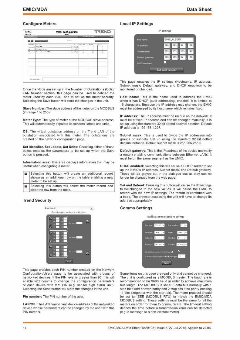
Network Configuration
OS icons
This page enables the following network items to be accessed:
Number of Outstations (OSs)/Lan Number (virtual network configuration - add or delete outstation/set up LAN number)vCNCs for the EMIC (view vCNC parameters)Time & Date (set time and date for EMIC)UDP group (the Ethernet UDP group to which it belongs)
When an outstation is created in the Number of Outstations (OSs)/Lan Number section, a record is set up for the outstation, and an OS icon is added to the left side of the page. The OS’s record is selected using the vertical scroll bar, and clicking on the OS’s icon. This enables access to the following for the selected meter:
Address moduleSensorsUsers
Number of Outstations (OSs)/Lan Number
Num. OSs: This shows the number of outstations set up.
An outstation can be added using the + button, or deleted using the - button. An existing outstation (including all its details) can be duplicated using the x2 button. Outstations can be created in the address range 1 to 119 excluding 2, 3, 20. Once the vOSs are created they should be set up with their meters using the meter configuration described later in this document.
Lan Number: This shows the LAN number for the EMIC’s LAN which includes all the vOSs. It enables the EMIC’s LAN number to be set up or changed.
VCNC
External vCNC internal vCNC
On entry one of the vCNC’s Ethernet node number, Port number and Timeout are shown.

12 EMIC/MDA Data Sheet TA201081 Issue 8, 27-Jul-2015. Applies to v2.06.
EMIC/MDA Data Sheet
VCNC (continued)Selecting the right arrow displays the same parameters for the other vCNC.
It is recommended that the EMIC’s vCNCs should not be used to connect to the system.
Time and Date
The EMIC contains a real time clock which is used to measure plot intervals and time stamp alarm messages. This page enables the time (24 hour notation), date (day, month, year) to be monitored and changed. The real time clock can be synchronised by a system timemaster, which would automatically re synchronise it at 00.05 hours. The clock is maintained for 7 days by a supercapacitor in case of power failure.
UDP group
Only devices in the same UDP (User Diagram Protocol) group can construct a communication network, so the other devices on the network (including across internetwork) must use the same UDP group number. This defaults to 57612.
GUID
The Human and Machine GUIDs are used on multi-site systems to identify the source of IP alarms. On a site with multiple Trend devices both GUIDs must all be set to match those of the other devices on the site.
Address ModuleSelected outstation (meter)
Identifier: The identifier of the virtual outstation, normally meter name.
Use IP Alarms: If this is unchecked the alarms (vOS sensor alarms) will be sent to a Trend address (device address, LAN number), but if checked the alarms will be sent to an IP address (IP address, port number). The receiving device will normally be a supervisor or display panel.
Alarm address: The device address on the Trend network to which the alarms are sent.
On remote LAN: The LAN number of the device to which the alarms are sent.
IP: The IP address of the device to which alarms are sent (e.g of format 192,168.2.28).
Port: The port address to which alarms are sent (e.g. 2774).
Sensors
This page is populated when the meter type is selected on the Meter Configuration page, and the Save button is selected (with appropriately enabled check boxes). This will set up the labels and units according to the pre-defined table for the particular meter type (see ‘Meter Points’ on page 4’). This page also displays the last received value for each sensor, and includes parameters to define and enable required high and low alarms, and to determine plot intervals and enable individual plots. Selecting the Send button will store the changes in the unit.
Label: The label of the sensor - normally pre-loaded from the table, but can be edited if required.
Value: Current value of the sensor.
Units: The units for the sensor - normally pre-loaded from the table, but can be edited if required.
H. Lim./L.Lim.: The high and low alarm limits for the sensor. Can be edited. The high limit must be higher than the low limit.
H. Enab./L. Enab.: Check the appropriate boxes to enable the High and/or Low alarms to be reported.
Plot: Check the box to enable the sensor to be plotted.
Plot Interval: This sets the plot interval in the range:1 m, 5 m, 10 m, 15 m, 20 m, 30 m, 1 h, 6 h, 24 h.
Set all: Checking this box will set all the sensors to be plotted at the interval specified
Users
This page enables the EMIC security to be set up. This applies to text comms being received by the EMIC.
There are up to 6 users each with a 4 digit PIN number and an associated PIN level. The administrator level (level 99) should be set up first. Selecting the Save button will store the changes.
Pin Number: A four digit PIN number in range 0000 to 9999
Pin Level: A PIN authority level in the range 0 to 99. A PIN level of 95 or greater is required to change module parameters; a PIN of level less than 95 can only read parameters.

EMIC/MDA Data Sheet TA201081 Issue 8, 27-Jul-2015. Applies to v2.06. 13
Data Sheet EMIC/MDA
Calculator
The Calculator page shows the calculations that have been setup in the EMIC. This enables a number of calculations (maximum 1000) to be set up; each will have an index number and label, each can have a sequence of up to 5 operations, and each is performed at a defined frequency.
This feature is used to calculate the Cumulative kWh for each meter. This requires 3 calculations for each meter:
Calculation 1 Copy Total Active Energy (S1) to S27 (performed once a period).
Calculation 2 Copy Calculated difference from S28 to S26 (performed once a period).
Calculation 3 Calculate difference between Current Total Active Energy (S1) and the last value stored in S27; store in S28 (performed as often as possible).
S26 is the Cumulative kWh taken over the period and is displayed on the web page.
S27 is the latest Total Active Energy value stored at the beginning of the period (not displayed on the web page)
S28 is the accumulating kWh; the energy consumed so far into the period (not displayed on the web page)
If required these calculations must be set up in the EMIC.
The buttons along the top operate as follows:
Add a calculation to next available index
Add a new row before selected index
Delete calculation at selected index
Replicates an existing calculation a defined number of times automatically changing the outstation or sensor numbers as required.
Clicking on a calculation shows the details of its operations in the schematic diagram below.
Frequency
Source operand configuration
Destination configuration
Operation 1 configuration
The diagram shows the calculation as a sequence of 5 operations. The first operation has 2 inputs (source operand input A, and input B), and each subsequent operation takes the previous output and another input, and the output of the final operation is the output of the complete calculation.
For Calculation 3, only the first operation is set up so that all 4 subsequent operations just pass operation 1’s calculated value through. Operation 1 is set up with inputs S1 and S27, and performs function A-B (i.e. S1-S27).
Clicking on the frequency icon enables the period to be set up. This calculation is set to ‘Every given second’ at 1 second, but calculations 1 and 2 are set to occur ‘Every given minutes’.
When set to ‘Every given minutes’ the ‘Parameter’ must be set up to define the number of minutes. This enables the user to select Cumulated kWh over 15 mins, 30 mins, 1 hour etc..
Clicking on the Source Operand configuration icon enables the first operation source A to be defined.
Operand Type: These calculations use a module output, but it can also be a constant (in which case the fixed value can be entered).
OS: The source outstation number.
Module type: This must be set to ‘Sensor (S)’.
Module number: The sensor number.
Clicking on the first operation setup icon enables the first operation to be configured. This is only set up for calculation 3.
Operation type: Set to A-B for calculation 3.
Operand Type, OS, Module type, and Module number are of the same function as those in the source operand setup but refer to the operations’s input B. For calculation 3 it is set to outstation 20, sensor 27.
14 EMIC/MDA Data Sheet TA201081 Issue 8, 27-Jul-2015. Applies to v2.06.
EMIC/MDA Data Sheet
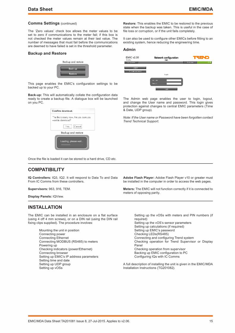
Configure Meters
Once the vOSs are set up in the Number of Outstations (OSs)/LAN Number section, this page can be used to defined the meter used by each vOS, and to set up the meter security. Selecting the Save button will store the changes in the unit.
Slave Number: The slave address of the meter on the MODBUS (in range 1 to 255).
Meter Type: The type of meter at the MODBUS slave address. This will automatically populate its sensors’ labels and units.
OS: The virtual outstation address on the Trend LAN of the outstation associated with this meter. The outstations are created on the network configuration page.
Set Identifier, Set Labels, Set Units: Checking either of these boxes enables the parameters to be set up when the Save button is pressed.
Information area: This area displays information that may be useful when configuring a meter.
Selecting this button will create an additional record shown as an additional row on the table enabling a new meter to be set up.Selecting this button will delete the meter record and clear the row from the table.
Trend Security
This page enables each PIN number created on the Network Configuration/Users page to be associated with groups of networked devices. If the PIN level is greater than 95, this will enable text comms to change the configuration parameters of each device with that PIN (e.g. sensor high alarm limit). Selecting the Send button will store the changes in the unit.
Pin number: The PIN number of the user.
LAN/OS: The LAN number and device address of the networked device whose parameters can be changed by the user with this PIN number.
Local IP Settings
This page enables the IP settings (Hostname, IP address, Subnet mask, Default gateway, and DHCP enabling) to be monitored or changed.
Host name: This is the name used to address the EMIC when it has DHCP (auto-addressing) enabled. It is limited to 15 characters. Because the IP address may change, the EMIC must be addressed by its host name which remains fixed.
IP address: The IP address must be unique on the network. It must be a fixed IP address and can be changed manually. It is set up using the standard 32 bit dotted decimal notation. Default IP address is 192.168.1.227.
Subnet mask: This is used to divide the IP addresses into groups or subnets. Set up using the standard 32 bit dotted decimal notation. Default subnet mask is 255.255.255.0.
Default gateway: This is the IP address of the device (normally a router) enabling communications between Ethernet LANs. It must be on the same segment as the EMIC.
DHCP enabled: Selecting this will cause a DHCP server to set up the EMIC’s IP address, Subnet mask, and Default gateway. These will be greyed out in the dialogue box as they can no longer be changed from the web page.
Set and reboot: Pressing this button will cause the IP settings to be changed to the new values. It will cause the EMIC to restart with the new IP settings. The restart is confirmed with a beep. The browser accessing the unit will have to change its address appropriately.
Comms Settings
Some items on this page are read only and cannot be changed. The unit is configured as a MODBUS master. The baud rate is recommended to be 9600 baud in order to achieve maximum bus length. The MODBUS is set at 8 data bits normally with 1 stop bit if odd or even parity and 2 stop bits if no parity (making 11 bits altogether with the start bit). The meter protocol should be set to IEEE (MODBUS RTU) to match the EMIC/MDA MODBUS setting. These settings must be the same for all the meters on order for them to communicate. The timeout setting defines the time before a transmission error can be detected (e.g. a message to a non-existent meter).
EMIC/MDA Data Sheet TA201081 Issue 8, 27-Jul-2015. Applies to v2.06. 15
Data Sheet EMIC/MDA
Comms Settings (continued)
The ‘Zero values’ check box allows the meter values to be set to zero if communications to the meter fail; if this box is not checked the meter values remain at their last value. The number of messages that must fail before the communications are deemed to have failed is set in the threshold parameter.
Backup and restore
This page enables the EMIC’s configuration settings to be backed up to your PC.
Back-up: This will automatically collate the configuration data ready to create a backup file. A dialogue box will be launched on you PC.
Once the file is loaded it can be stored to a hard drive, CD etc.
restore: This enables the EMIC to be restored to the previous state when the backup was taken. This is useful in the case of file loss or corruption, or if the unit fails completely.
It can also be used to configure other EMICs before fitting to an existing system, hence reducing the engineering time.
Admin
The Admin web page enables the user to login, logout, and change the User name and password. This login gives protection against changes to central EMIC parameters (Time & Date, UDP group).
Note: If the User name or Password have been forgotten contact Trend Technical Support.
COMPATIBILITYIQ Controllers: IQ3, IQ2. It will respond to Data To and Data From IC Comms from these controllers.
Supervisors: 963, 916, TEM.
Display Panels: IQView.
Adobe Flash Player: Adobe Flash Player v10 or greater must be installed in the computer in order to access the web pages.
Meters: The EMIC will not function correctly if it is connected to meters of opposing parity.
INSTALLATIONThe EMIC can be installed in an enclosure on a flat surface (using 4 off 4 mm screws), or on a DIN rail (using the DIN rail fixing clips supplied). The procedure involves:
Mounting the unit in positionConnecting powerConnecting EthernetConnecting MODBUS (RS485) to metersPowering upChecking indicators (power/Ethernet)Connecting browserSetting up EMIC’s IP address parametersSetting time and dateSetting up UDP groupSetting up vOSs
Setting up the vOSs with meters and PIN numbers (if required)Setting up the vOS’s sensor parametersSetting up calculations (if required)Setting up EMIC’s passwordChecking LEDs(RS485)Connecting and configuring Trend systemChecking operation for Trend Supervisor or Display PanelChecking operation from supervisorBacking up EMIC configuration to PCConfiguring IQs with IC Comms
A full description of installing the unit is given in the EMIC/MDA Installation Instructions (TG201082).

16 EMIC/MDA Data Sheet TA201081 Issue 8, 27-Jul-2015. Applies to v2.06.
EMIC/MDA Data Sheet
Please send any comments about this or any other Trend technical publication to [email protected]
© 2015 Honeywell Technologies Sàrl, ECC Division. All rights reserved. Manufactured for and on behalf of the Environmental and Combustion Controls Division of Honeywell Technologies Sàrl, Z.A. La Pièce, 16, 1180 Rolle, Switzerland by its Authorized Representative, Trend Control Systems Limited.
Trend Control Systems Limited reserves the right to revise this publication from time to time and make changes to the content hereof without obligation to notify any person of such revisions or changes.
Trend Control Systems LimitedAlbery House, Springfield Road, Horsham, West Sussex, RH12 2PQ, UK. Tel:+44 (0)1403 211888 Fax:+44 (0)1403 241608 www.trendcontrols.com
DISPOSALCOSHH (Control of Substances Hazardous to Health - UK Government Regulations 2002) ASSESSMENT FOR DISPOSAL OF EMIC/MDA.
RECYCLING .All plastic and metal parts are recyclable. The printed circuit board may be sent to any PCB recovery contractor to recover some of the components for any metals such as gold and silver.
wEEE Directive:
At the end of their useful life the packaging, and product should be disposed of by a suitable recycling centre.
Do not dispose of with normal household waste.Do not burn.
OrDEr CODESEMIC/MDA/8 :Ethernet Metering Interface Controller for 8 specified Modbus meters (includes RS485
cable and DIN rail mounting kit).EMIC/MDA/16 :Ethernet Metering Interface Controller for 16 specified Modbus meters (includes RS485
cable and DIN rail mounting kit).EMIC/MDA/32 :Ethernet Metering Interface Controller for 32 specified Modbus meters (includes RS485
cable and DIN rail mounting kit).
SPECIFICATIONSELECTrICAL
Power Supply Input :24 Vdc ±15% regulatedSupply Current :300 mA at 24 Vdc supplyEthernet :10 BASE-TMODBUS :(RS485) 11 bit character, 1 start bit, 8
data bits. Parity selectable (none, odd, or even). Odd or even parity have 1 stop bit, no parity has 2 stop bits.
Option of 7 data bits.Reset button :Restarts EMICPower fail :Configuration data stored to flash
memory, and Time and Date supported for up to 7 days by supercapacitor if power fails.
Indicators Power :Green LEDSystem Ready :Green LEDEthernet :Green LEDM-Bus P1 :Green/Yellow) LED
MECHANICAL
Dimensions :77 mm x 108 mm x 26 mm (3.03” x 4.25” x 1.02”)
:77 mm x 108 mm x 45 mm (3.03” x 4.25” x 1.77”) - includes DIN rail clips
Weight :330g (11.6 ozs) including DIN rail clips 410 g (14.4 ozs) shipped including DIN
rail clipsConnectors
Power :2 part connector with 2 screw terminals for 0.5 to 2.5 mm2 cross section area (20 to 14 AWG) cable.
Ethernet :RJ45 connector, unshielded or shielded twisted pair (UTP or FTP) cable 10 Mbps 100m (109 yds), 10 BASE-T. Connect via adjacent hub or directly using standard Ethernet cable with crossover adaptor.
MODBUS (P1) :(RS485) RJ45 connector. Connect to meter using adaptor cable supplied (2.5 m)
Operating Temperature :0 to 70 °C (32 to 158 °F)Regulation :CE Class A, FCC Class A