emotiglass - v4 - diy physics blog · the emotiglass prototype developed under this project shall...
TRANSCRIPT

© 2018, D. Prutchi, J. Meyers, EmotiGlass 1
EmotiGlass David Prutchi and Jason Meyers
V.4.0 Release – October 21, 2018
All augmented reality devices so far provide an interactive experience of the real‐world environment that
is enhanced by computer‐generated perceptual information. In contrast, the EmotiGlass project explores
ways in which a computer can modulate the user’s EMOTIONAL perception of reality. Our projects aims
to develop the first “Modulated‐Emotion Reality” device. EmotiGlass enables completely new
applications in the field of augmented reality in which emotional biases can be manipulated by computer
applications. Additionally, EmotiGlass has potential therapeutic applications as an aid to help control
stress and anxiety.
To demonstrate and develop the EmotiGlass concept, a wearable prototype was designed and
constructed. This open‐source project was designed from the beginning to be easy to build using tools
and materials widely available to makers and hobbyists. Full design files and detailed build instructions
are available at the hackaday.io project page so that anyone can reproduce or extend the EmotiGlass
design.
NOTE: The potential therapeutic applications for EmotiGlass have not been reviewed by FDA or any other
regulatory agency. Please see complete disclaimer in Section 10.

© 2018, D. Prutchi, J. Meyers, EmotiGlass 2
Table of Contents 1 Background ........................................................................................................................................... 3
2 The EmotiGlass Concept and Conceptual Requirements ..................................................................... 7
2.1 EmotiGlass Conceptual Requirements Specification .................................................................... 8
2.1.1 Hardware............................................................................................................................... 8
2.1.2 Firmware ............................................................................................................................... 8
2.1.3 User Interface ........................................................................................................................ 9
3 Operating Modalities ............................................................................................................................ 9
3.1 Visual Occlusion Synchronized to Baroreceptor Activation .......................................................... 9
3.2 Lateralized Brain Stimulation ...................................................................................................... 11
3.3 Swept‐Visual Stimulation ............................................................................................................ 14
3.4 Interoception Enhancement ....................................................................................................... 15
3.5 Automatic Sunglasses ................................................................................................................. 16
4 Basic Hardware Selection .................................................................................................................... 16
5 EmotiGlass Development .................................................................................................................... 17
5.1 First Conceptual Prototype Breadboard ..................................................................................... 17
5.2 Wearable Prototype Design ........................................................................................................ 19
5.2.1 Electronics ........................................................................................................................... 19
5.2.2 Mechanical .......................................................................................................................... 20
5.2.3 Firmware ............................................................................................................................. 21
6 GUI Design ........................................................................................................................................... 23
6.1 Initial GUI Screen ......................................................................................................................... 23
6.2 Clear ............................................................................................................................................ 23
6.3 Dark ............................................................................................................................................. 24
6.4 Auto‐Dark .................................................................................................................................... 24
6.5 Lateralized Brain Stimulation ...................................................................................................... 25
6.6 Visual Occlusion Synchronized to Baroreceptor Activation ........................................................ 26
6.7 Visual Sweep ............................................................................................................................... 27
6.8 GUI Installation and Development .............................................................................................. 28
7 Compliance with Requirements and Final Specifications ................................................................... 30
7.1 Compliance with Requirements .................................................................................................. 30
7.2 Specifications .............................................................................................................................. 32
8 Further Development and Productizing EmotiGlass ........................................................................... 33

© 2018, D. Prutchi, J. Meyers, EmotiGlass 3
8.1 Electronics ................................................................................................................................... 34
8.2 Enclosure ..................................................................................................................................... 34
8.3 Firmware ..................................................................................................................................... 35
8.4 GUI .............................................................................................................................................. 35
8.5 Other ........................................................................................................................................... 35
9 Licenses ............................................................................................................................................... 35
10 Disclaimer ........................................................................................................................................ 36
11 Acknowledgements ......................................................................................................................... 37
12 References ...................................................................................................................................... 37
Appendices .................................................................................................................................................. 39
A. EmotiGlass Wearable Prototype Schematics .................................................................................. 39
B. PCB Drawings and Assembly Notes ................................................................................................ 43
C. Wiring Information ......................................................................................................................... 44
D. Bill of materials ............................................................................................................................... 45
E. Build Instructions ............................................................................................................................ 47
1 Background Does the sight of a dog make you happy or fearful? Are you comfortable around people of other races?
We commonly think that the emotions aroused by events around us are the results of our biases and prior
experiences. This is very true, but there is much more than meets the eye when it comes to understanding
the way in which our brains attach emotional content to our perceptions.
We develop implantable cardiac medical devices for a living, and a few months ago, we came across an
interesting journal article that caught our curiosity. In this paper [Azevedo, et al. 2017], researchers from
the University of Sussex and the Royal Holloway University of London showed that presenting an image
at different periods of the cardiac cycle would cause changes in the way that subjects would emotionally
perceive that image.
The paper reported that racial biases could clearly be modulated by changing the timing at which an image
is presented. In this study, pictures of dark‐skinned or light‐skinned individuals holding various objects
were presented to coincide with either the heart’s contraction (cardiac systole) or relaxation (diastole)
(Figure 1). Results showed that if the image was presented during cardiac systole, subjects significantly
misidentified innocuous objects as weapons when they were held by dark‐skinned people (Figure 2).
Remarkable!

© 2018, D. Prutchi, J. Meyers, EmotiGlass 4
Figure 1 – In the study conducted by Azevedo, et al. [2017], participants were presented for a brief period (200 ms) with pictures of a light‐skinned or dark‐skinned male holding either a weapon or a harmless object in his hand, and were asked to decide whether to ‘shoot’ or ‘don’t shoot’ him, respectively. Crucially, investigators time‐locked the presentation of the target to coincide either with the cardiac systole or the cardiac diastole.

© 2018, D. Prutchi, J. Meyers, EmotiGlass 5
Figure 2 – Participants in the study by Azevedo, et al. [2017] were more likely to ‘shoot’ unarmed dark‐skinned than unarmed light‐skinned individuals when stimuli was perceived during systole compared to when perceived during diastole.
A group from University College London conducted a related study [Gray, et al., 2009] through which they
found that sensory processing depends on when stimuli are experienced in relation to heartbeat timing.
Specifically, the perception of pain – which is strongly biased by emotion—varied depending on when
during the cardiac cycle noxious stimuli were delivered to the subjects.
As shown in Figure 3, the mechanism behind these effects seems to be that the emotional arousal caused
by a stimulus depends on signals being received by the brain from the body’s internal blood pressure
sensors (baroreceptors). Simply timing the delivery of stimuli against the cardiac cycle can change the
way in which the brain processes stimuli! 1
1 Two interesting presentations by University of Sussex researchers on these topics are available on YouTube:
Sarah N Garfinkel, “Interoceptive Signals from the Heart can Guide Cognitive and Perceptual Experience”, November 2017: https://youtu.be/WqRss1NnEII
Hugo Critchley, “Interoception, Emotion and Self: How the Heart Gates Feelings and Perceptions”, https://youtu.be/xGqr5buHsXc

© 2018, D. Prutchi, J. Meyers, EmotiGlass 6
Figure 3 – Baroreceptors are pressure sensors in the blood vessels which relay information to the brain so that the autonomic nervous system can maintain appropriate blood pressure. The firing frequency of these baroreceptors tracks the blood pressure wave (a). b) Baroreceptor signals also reach structures within limbic structures of the brain that are responsible for the perception of emotional salience. c) These structures “tag” sensory input with emotional content, and research shows that the intensity of the emotional response is modulated by baroreceptor firing.
It’s not only the timing component of a stimulus that can change the emotions that it arouses. The spatial
component also has major effects on the emotional perception of visual scenes. In his exciting book “Of
Two Minds: The Revolutionary Science of Dual‐Brain Psychology”, Dr. Fredric Schiffer [1998], a Professor
of Psychiatry at Harvard Medical School and Attending Psychiatrist at McLean Hospital, showed that very
distinct emotions can be evoked by selectively blocking access of the visual field to one of the brain’s
hemispheres.
Spatio‐temporal changes in the visual field also cause deep changes in emotional response. EMDR (Eye
Movement Desensitization and Reprocessing) [Shapiro, 2017] is a known psychotherapy technique
whereby causing side‐to‐side eye movements is believed to unlock a memory mechanism that can be used
to reprocess traumatic events. Outside of the therapeutic setting, mild side‐to‐side sweeping of the visual
field appear to decrease the emotional impact of distressing events.
The objective of the EmotiGlass project is to develop a pair of active glasses that can be controlled to
selectively occlude vision with the proper timing and/or spatial distribution to allow a computer to
modulate the user’s EMOTIONAL perception of reality. Unlike augmented‐reality devices that limit
themselves to enhancing reality with computer‐generated content, we aim to develop the first device that
can modulate the perceived emotional content of reality.

© 2018, D. Prutchi, J. Meyers, EmotiGlass 7
2 The EmotiGlass Concept and Conceptual Requirements
Figure 4 – Conceptual view of the EmotiGlass goggles
Figure 5 – Conceptual block diagram for the EmotiGlass goggles
Figure 4 presents a conceptual view of the EmotiGlass goggles, while Figure 5 presents a general block
diagram. The concept calls for eyewear frames with multi‐pixel light shutters that can be controlled by

© 2018, D. Prutchi, J. Meyers, EmotiGlass 8
an on‐board microcontroller to selectively occlude the visual field. Furthermore, the occlusion may be
timed to occur in synchrony with the cardiac cycle as detected by a photoplethysmographic sensor or an
ECG channel. The emotional valence of reality can then be modulated by a computer or by the user
through a user interface. For the sake of convenience, the eyewear can incorporate all of the real‐time
electronics, while control of operating mode can be done wirelessly via BLE.
The therapeutic applications of EmotiGlass are obvious as an aid to help control stress and anxiety.
However, EmotiGlass enables completely new applications in the field of augmented reality. For example,
the emotional biases of police and other first responders could be dampened to lessen inappropriate use
of force. On the other hand, increased emotional arousal could be used in entertainment applications to
enhance movies and gaming applications.
2.1 EmotiGlass Conceptual Requirements Specification The EmotiGlass prototype developed under this project shall fulfill the following requirements:
2.1.1 Hardware 1. The EmotiGlass device shall be constructed as goggles wearable by an adult user.
2. The EmotiGlass device shall incorporate a microcontroller to control its operation such that
further development can be done by reprogramming the device with no need for hardware
changes.
3. The EmotiGlass device shall incorporate a sensor for detecting the wearer’s heartbeat.
4. The EmotiGlass goggles shall be stand‐alone (with exception of the GUI device) and be fully self‐
contained.
5. The EmotiGlass goggles shall be controlled via a wireless user interface, preferably one that can
run as an app on the user’s smartphone or similar portable device.
6. Hardware selected for the EmotiGlass Device shall be widely available. With the exception of
custom PCBs and frame, all electronic components shall be in current production and available in
small quantities from easily‐accessible vendors to enable experimenters to replicate the device
for personal use.
2.1.2 Firmware 1. The firmware for the EmotiGlass device shall implement the following operating modes:
a) Clear
b) Dark
c) Auto‐Dark
d) Lateralized Brain Stimulation
e) Occlusion synchronized to Baroreceptor Activation
f) Interoceptive Awareness
g) Visual Sweep
2. The firmware for the EmotiGlass device shall implement the logic layer for communicating with
the wireless user interface, preferably one that can run as an app on the user’s smartphone or
similar portable device.
3. Firmware shall be written in an easily‐accessible language, and shall use only open‐source
modules to enable experimenters to replicate and modify the device for personal use.

© 2018, D. Prutchi, J. Meyers, EmotiGlass 9
2.1.3 User Interface 1. The user interface shall be intuitive and easy to use
2. If possible, the user interface shall run as an app on the user’s smartphone or portable device
3. Software for the user interface Firmware shall be written in an easily‐accessible language, and
shall use only open‐source modules to enable experimenters to replicate and modify the device
for personal use.
3 Operating Modalities
3.1 Visual Occlusion Synchronized to Baroreceptor Activation It has been demonstrated that visceral afferent signals to the brain influence thoughts, feelings, and
behavior regardless of whether or not these signals reach conscious awareness. For example,
experiments performed by Critchley and his collaborators [Gray et al. 2011, Critchley et al. 2015] at the
University of Sussex (Brighton, UK) have shown that the emotional centers of the brain more easily detect
fear and assign greater emotional salience to stimuli presented during cardiac systole than when
presented at diastole.
In these experiments, subjective and brain responses were measured to pictures of faces showing
emotions presented before and during cardiac systole. Facial expressions of disgust were judged as more
intense when presented at systole, and rebound heart rate increases were reduced after expressions of
disgust and happiness. Neuroimaging studies showed that activity in the emotional centers of the brain
changed with cardiac timing. As mentioned in the background section, such timing‐dependent changes
influence emotional judgements, so powerfully that test subjects erred in the identification of items as
weapons when held by people with dark skin, but not by people with light skin if the images are presented
during cardiac systole. It is thus indisputable that there exists a close coupling of visceral and emotional
processes, and that regions in the body that receive internal information have a strong influence on
affective judgment.
Selectively occluding vision during parts of the cardiac cycle thus makes it possible to modulate the
emotional response to a scene. As shown in Figure 6, visual blanking may be synchronized to cardiac
activity either by using the ECG signal, or the plethysmography signal (which may be detected using the
light reflected off the skin as blood enters and leaves the small blood vessels near the pickup sensor). As
depicted in Figure 7, the hypothesis is that this will reduce the intensity of the emotional content assigned
to the scene by the limbic system.

© 2018, D. Prutchi, J. Meyers, EmotiGlass 10
Figure 6 – Visual occlusion may be applied in synchrony with either the top‐of‐R of the ECG (left) or when the pulse plethysmography signal crosses a certain threshold.
Figure 7 – The EmotiGlass device allows the user to see a scene while baroreceptor firing is low (a and d), but blocks the scene when baroreceptor activity is high (b and c). The hypothesis is that this will reduce the intensity of the emotional content tagged to the scene by the limbic system (see Figure 3)

© 2018, D. Prutchi, J. Meyers, EmotiGlass 11
Photoplethysmography is probably the better alternative because it requires just a LED and a photosensor
placed in contact with the skin to detect the heartbeat. The ear lobe or skull are good points to place the
sensor, and calculating timing is not necessary because the pressure signal detected at those locations is
virtually the same as that which excites the baroreceptors that innervate the brain.
3.2 Lateralized Brain Stimulation It is well known from the study of split‐brain patients that the right brain and left brain are capable of
having their own mentation and actions, whereby the right hemisphere can have intact mental faculties,
separate from and often beyond the awareness of a person's left‐sided mind. Dr. Fredric Schiffer [1998],
a professor of psychiatry at Harvard Medical School and Attending Psychiatrist at McLean Hospital, has
demonstrated that this is not only the case in split‐brain patients, but rather that everyone has two
autonomous minds ‐ one associated with the left brain and one with the right brain ‐ and that in healthy
individuals, these two minds cooperate harmoniously towards a balanced personality.
However, troubling behavioral symptoms may happen when a strong imbalance exists between the two
minds since an unhealthy person‐to‐person relationship can develop between these two autonomous
minds, whereby the same type of psychological issues and conflicts that would apply between two people
may apply to the relationship between the two minds in a single individual. The dominant hemisphere
can thus markedly and negatively affect an individual’s personality.
Dr. Schiffer [1999] 2 uses glasses that selectively occlude vision such that only one side of the brain is
stimulated, having static transparent and opaque regions to selectively stimulate only the right brain or
the left brain (Figure 8, left). When used during a psychotherapy session, a patient can be asked to
alternate between lateral visual fields and induce both an increase and a decrease in his symptoms to
show him that his fears reside only in a part of his mind. The glasses can also be used outside the context
of a psychotherapy session in order to reduce stress and anxiety. These glasses have fixed occlusion zones
and thus need to be specifically constructed for each user.
Based on Schiffer’s work, others have designed therapeutic glasses using moveable screens to selectively
occlude the patient’s vision. For example, in U.S. Patent No. 6,141,797 “Opaque goggles having openable
window” (Figure 8, right), Robert Buck describes glasses that have moveable opaque windows. These are
commercially available under the name “NeuView” (www.neuviewglasses.com).
2 An ABC 20/20 segment on this topic is available at: https://youtu.be/dSq3kkINe10

© 2018, D. Prutchi, J. Meyers, EmotiGlass 12
Figure 8 – Goggles of the type used by Dr. Fredric Schiffer to selectively occlude vision such that only one side of the brain is stimulated.
These existing eyeglasses for selective lateral stimulation are simple devices through which the temporal
and spatial distribution, as well as magnitude of the occlusion cannot be finely controlled. In addition,
these devices do not look like regular eyewear, thus attracting attention, which may be undesirable when
treating stress, anxiety, and other mental disturbances.
In contrast, the EmotiGlass goggles can selectively block a subject’s field of vision with controllable spatial
distribution and magnitude of the occlusion, and when fully developed into a product, can do so while
maintaining the semblance of a normal pair of sunglasses.
The science behind this modality is fascinating! The basic principle is that the right brain and left brain
are capable of having their own mentation and actions, whereby the right hemisphere can have intact
mental faculties, separate from and often beyond the awareness of one’s left‐sided mind. As such, a
person can have two autonomous minds, one associated with the left brain and one with the right brain.
Schiffer [1998] has demonstrated that a person‐to‐person relationship can develop between these two
autonomous minds, whereby the same type of psychological issues and conflicts that would apply
between two people may apply to the relationship between the two minds in a single individual. The
dominant hemisphere can often markedly determine a person's personality.
For example, in a certain person the left mind might “dominate” and “suppress” his right mind. In another,
the right mind may be dominant. In mentally‐healthy people, the two minds coexist in harmony with
mutual respect and cooperation. However, troubling behavioral symptoms may happen when a strong
imbalance (and hence conflict) between the two minds occurs.
According to Schiffer’s experiments, those who have been affected by emotional trauma lateralize the
effects, perhaps in an effort to maintain more‐or‐less‐normal functioning. One hemisphere or the other
gets stuck in the past, and acts out through the patient's symptoms.
Schiffer has demonstrated that by restricting vision to a portion of the retina of an eye that is connected
to a particular hemisphere of the brain, that hemisphere can be stimulated preferentially, causing changes
in the psychological state of a person that may be therapeutically beneficial.
This is possible because the eyes are connected to the brain so that vision to the left side of a person goes
primarily to the opposite (right) hemisphere and vision to the right side of a person goes primarily to the
left hemisphere. Figure 9 shows that the image of objects are projected by the lenses onto the retinas.

© 2018, D. Prutchi, J. Meyers, EmotiGlass 13
Each retina is divided into a medial and lateral aspect. Image points projected on the lateral aspect of the
retina of the left eye go directly to the brain’s left hemisphere, while points projected on the medial aspect
of the retina of the left retina go to the brain’s right hemisphere. Similarly, image points projected on the
lateral aspect of the retina of the right eye go directly to the brain’s right hemisphere, while points
projected on the medial aspect of the retina of the left retina go to the brain’s left hemisphere. Images
conveyed to only one hemisphere by the optic nerves can be communicated to the other hemisphere via
the corpus callosum.
Figure 9 – Connections between the eyes and the brain. Left: Healthy. Right: Lateralized vision in split‐brain patient
For the lateralized brain stimulation modality, the glasses need to occlude the visual field such that only
the parts of the retinas that innervate the left or right brain are illuminated by the scene. This requires at
least four distinct vertical regions as shown in Figure 10.

© 2018, D. Prutchi, J. Meyers, EmotiGlass 14
Figure 10 – Distribution of occlusion for lateralized brain stimulation. Figure on the left shows the configuration to preferentially stimulate the subject’s right brain hemisphere through both direct innervation (from the right retina’s lateral aspect) and contralateral innervation (from the left retina’s medial aspect).
The front side of the glasses need to be able to create a clear window of around 1cm width (or narrower),
and it should be programmable to allow fine tuning for each individual. A good programmability range
would be between 4 mm and 20 mm with 2mm resolution. It must be noted that since vision in the far
periphery of the visual field has low resolution, replacing the side shutters by simple light valves (not
pixelized, one for each side) should not result in any loss of therapeutic effectiveness.
3.3 Swept‐Visual Stimulation Eye Movement Desensitization and Reprocessing (EMDR) therapy was born in 1987 when psychologist Dr.
Francine Shapiro realized that side‐to‐side eye movements appeared to decrease the negative emotion
associated with her own distressing memories. She hypothesized that eye movements had a desensitizing
effect, and went on to test it under controlled clinical conditions [Shapiro, 2017].
The concept has led to a standard procedure that is commonly used to treat victims of psychological
trauma. Although the underlying mechanism is not known, it has been hypothesized that side‐to‐side
movement of the eyes activates the same neuronal networks responsible for REM sleep. Experimental
evidence seems to indicate that actual eye movement is not necessary, and that the same neural
activation can be elicited by side‐to‐side movements in the light patterns of the visual field.
It is thus hypothesized that sweeping a clear window back‐and‐forth through EmotiGlass will decrease the
emotional impact of distressing events.

© 2018, D. Prutchi, J. Meyers, EmotiGlass 15
Figure 11 – Swept visual stimulation with the EmotiGlass goggles.
For this modality, as shown in Figure 11, the clear window should have an approximate width of 1cm,
while the opacity of the occluded area should have a programmable range of about 20% of the clear
window and up to 100%. In classical EMDR, the approximate sweeping rate used to solidify a positive
experience is approximately 0.5 to 1Hz, while reprocessing of traumatic memories is done in a therapeutic
setting at sweep frequencies of up to 3 Hz. The most common spatial pattern is simple side‐to‐side, but
diagonal or figure‐of‐8 sweeps are also used, especially in conjunction with fast movements.
3.4 Interoception Enhancement Interoreceptive awareness is our sensitivity to our own internal sensations. Receptors throughout our
body gather information that enables us to feel hunger, satiety, itch, internal pain, body temperature,
nausea, need for the bathroom, tickles, physical exertion, sexual arousal, and other internal states.
Sensations from the interoceptive system alert us that our internal system is out of balance and requires
us to take action to restore the balance. For example, the sensation of thirst compels us to drink in order
to restore the body’s electrolyte concentration that is unbalanced by the loss of fluids to sweat and
urination.
Introceptive sensations are also important in the way in which we perceive, conceptualize, and remember
our affective experiences and other cognitive processes. These sensations allow us to feel our emotions.
For example, before speaking in public, we may feel our heart racing, slight nausea, muscle tension, and
shakiness in our hands. Not feeling these sensations would make it difficult to clearly identify the
emotions of anxiousness and nervousness.

© 2018, D. Prutchi, J. Meyers, EmotiGlass 16
Not being able to interpret our interoceptive signals in itself causes anxiety, and many biofeedback
techniques rely in fact on helping people learn how to “read” their own body. For example, a well‐
conducted study demonstrated that improving heartbeat perception in patients with medically‐
unexplained symptoms reduces symptom distress [Schaefer, 2014]. In addition, anxiety in autistic
individuals has been shown to decrease quite dramatically when heartbeat feedback is provided to the
subject, and is now the subject of a controlled clinical trial [Critchley, 2017].3
The EmotiGlass goggles are fully equipped to unobtrusively provide direct heartbeat feedback to the user,
for example by diming the side panels in synchrony with the plethysmographic signal. In fact, after the
subject is “trained” to perceive the side dimming as a proxy for heartbeat, the rhythm of the dimming can
be artificially modulated by a computer to change the emotional state of the user.
3.5 Automatic Sunglasses Although not a feature to modulate the emotional response of the user, automatically‐darkening
sunglasses can be easily implemented by the addition of a light sensor, so why not…
4 Basic Hardware Selection From the discussion above, and as shown in Figure 4, a practical implementation of the EmotiGlass
concept requires a pixelized light shutter with the following characteristics:
Spatial resolution of at least 2mm
Variable opacity and high contrast
Response speed in the tens of milliseconds or better
After researching possible solutions for fully pixelized electro‐optical elements, we settled on modular
LCDs for the front lenses. We chose the DOGM128E‐6 made by Electronic Assembly GmbH (Zeppelinstraße
19, D‐82205 Gilching, Germany) because it allows full control of the pattern of visual occlusion, as well as
the opacity level of the occluded and non‐occluded areas. The DOGM128E‐6 is sold by Mouser and Digikey
(around $23 each).
The DOGM128E‐6 (Figure 12) is a high‐contrast, 128x64 pixel LCD supertwist display with 15μm dot gap.
It incorporates a ST7565R controller with SPI interface. The display module requires just a single 3.0 to
3.3V power supply (270μA typical) and can be directly mounted on a PCB. The LCD is compact (55x46x2
mm) with a large viewing area of 51x31 mm.
3 Short videos about this research are available from the BBC at: http://www.bbc.com/future/story/20180423‐how‐a‐s

© 2018, D. Prutchi, J. Meyers, EmotiGlass 17
Figure 12 – The DOGM128E‐6 is a high‐contrast, 128x64 pixel LCD supertwist display with a large viewing area of 51x31 mm. It requires 9 external capacitors to operate from a 3.0 to 3.3V supply.
For the side panels we chose the “Small Liquid Crystal Light Valve ‐ Controllable Shutter Glass” distributed
by Adafruit as Product number 3627 ($2.95 each). The viewing window is 31x33 mm, while the panel size
is 36x36x2 mm, making it suitable to mount on the sides of goggles based on the DOGM128E‐6. The
device is a transmissive twisted nematic panel and requires an AC drive voltage in the 3.0V range.
5 EmotiGlass Development
5.1 First Conceptual Prototype Breadboard To make the EmotiGlass as open‐source as possible, we chose the controller to be an Arduino IDE‐
compatible Adafruit Feather M0 Bluefruit LE (Adafruit Product ID: 2995, $29.95). Power is derived from
a 3.7V 150mAh lithium ion polymer battery (Adafruit Product ID: 1317, $5.95) that can be recharged
directly from the Feather.
For the conceptual EmotiGlass prototype shown in Figure 13, we chose a ready‐made plethysmography
sensor (Pulse Sensor Amped, Adafruit Product ID: 1093, $25.00). A GA1A12S202 log‐scale analog light
sensor (on breakout board, Adafruit Product ID: 1384, $3.95) is used for the “automatic sunglasses mode”.
GUI control is via the Bluefruit Control Pad for iOS.
A simple oscillator and analog H‐bridge is used to drive the side panels at an amplitude set by two
MCP4725A1 DACs are used to control the side‐panel shutters (MCP4725 Breakout Board ‐ 12‐Bit DAC
w/I2C Interface, Adafruit Product ID: 935, $4.95).

© 2018, D. Prutchi, J. Meyers, EmotiGlass 18
Figure 13 – First breadboard prototype of the EmotiGlass goggles.
Code to run the EmotiGlass breadboard prototype was posted to the Hackaday.io project page for
EmotiGlass. A dedicated controller was then written under Evothings Studio as shown in Figure 14

© 2018, D. Prutchi, J. Meyers, EmotiGlass 19
Figure 14 – Dedicated BLE controller for the first breadboard prototype of EmotiGlass
5.2 Wearable Prototype Design
IMPORTANT NOTE: The purpose of this section is to describe and explain the design. However, since
improvements are constantly being made to this project, please do not rely on the design files presented
in this document to construct an EmotiGlass device. The latest design files are available at
https://hackaday.io/project/160615/files
5.2.1 Electronics The circuitry for the EmotiGlass device is shown in the schematic diagrams in Appendix A. Although
simple, the circuit needed to be distributed so that it would fit the goggle frames, so it was partitioned
into four PCBs, and these schematics correspond to each of the PCBs.
Two boards are stacked together with the Adafruit Feather M0 Bluefruit LE (Adafruit Product ID: 2995).
The “Right Side” PCB is used as a convenient method for connecting with the LCDs, liquid‐crystal light
shutters, and battery board to board wires. This board also holds a SMD fuse in series with the battery,
and an ON/OFF switch that is used to disable the Feather M0.
The “Right Side Dev” PCB implements the DC‐to‐AC converter to drive the liquid‐crystal shutters.
Although the shutters darken when DC is applied, twisted‐nematic liquid‐crystal devices are damaged
over time through electromigration when under DC drive. For this reason, an oscillator built around U5A‐
U5D (CD40106BE) is used to drive the switches of two H‐bridges implemented through MAX392 quad
analog switches U1 and U3. These convert the DC levels produced by MCP4725A digital‐to‐analog
converters U2 and U4 into an AC signal to drive the liquid‐crystal shutters.

© 2018, D. Prutchi, J. Meyers, EmotiGlass 20
It must be noted that we have made provisions in the implementation to greatly simplify the electronics
at the expense of writing a custom driver by using the microcontroller’s PWMs. The idea is to set up two
PWMs 180° out of phase to produce the square wave with alternating polarity to drive the liquid‐crystal
shutter. Two pairs of PWMs would be needed to control the two shutters. Changing the pulse width
would then change the optical density of the LC shutter. This has the same effect as the current
implementation of varying the amplitude of the AC drive, but obviates the need for the DACs and DC‐to‐
AC circuitry.
The circuits for the front PCBs contain all of the capacitors needed by the charge pumps of the LCD drivers
shown in Figure 12. In addition to pass‐through connectors, the right‐front PCB differs from the left‐front
PCB because it also includes an Everlight ALS PT‐19 light‐to‐current sensor used to implement the auto‐
darkening sunglasses mode.
The PCBs were designed to use the largest surface‐mount packages available for ICs (mostly SOICs) and
0603 passives (with plenty of space between them) so that the boards will be reasonable easy to assemble
with only a basic soldering iron.
5.2.2 Mechanical The wearable prototype frame is 3D printed. The frame is designed in 3 pieces (front and 2 sides). This
allows the front piece which holds the glass LCD displays and shutters to be printed from a stiff plastic,
allowing it to provide the most protection possible to the glass. PLA is being used currently, but switching
to a CPE family material will allow the device to survive a higher temperature. At the same time, the sides
are printed from a more flexible material from the Nylon family (the prototype uses Taulman 645), which
allows the Emotiglass prototype to fit on heads of different sizes without being uncomfortable. The three
frame pieces are keyed together and secured with screws. The frame was designed to use the same size
screw everywhere except the board stack, and can use either inch or metric hardware. The mechanical
components are shown in Figure 15.
Figure 15 – EmotiGlass mechanical components

© 2018, D. Prutchi, J. Meyers, EmotiGlass 21
5.2.3 Firmware
WARNING: Firmware was written by hardware engineers. This code may be offensive to some audiences.
Reader discretion is advised.
The firmware for EmotiGlass is coded as a sketch under the Arduino Development Environment. Its
principal functions are:
Communicating with the GUI via BLE and setting operating parameters
Controlling the LCDs
Controlling the liquid crystal light shutters
Sampling the plethysmography signal
Sampling ambient illumination
The code itself, available at the project page is well documented, but some explanations regarding the
various functions are in order, as follows.
The occlusion areas in the LCDs are drawn using the function rectangle(start_column, start_page,
end_column, end_page, pattern) of the dog_7565R library. This function draws a filled rectangle on the
screen. The filling is given through the pattern byte. Variables are: start column (0..127), start page (0..7),
end column (0..127), end page (0..7), pattern‐byte. LCD coordinates are shown in Figure 16.
The “single pixel” liquid crystal shutter for the side of the visual field is considered to be the 128th column
(where LCD columns are 0…127). The single‐pixel shutters are controlled by leftsideEnable and
rightsideEnable.
This version of EmotiGlass limits the shape of the occlusion to be rectangular, where the full height (Pages
0 … 7, with full fill pattern) of each column is either filled or remains blank.
Contrast of the LCDs is controlled via DOG.contrast(0..63), while the optical density of the liquid‐crystal
shutters is controlled by leftsideContrast and rightsideContrast by writing to their respective MCP4725
digital‐to‐analog converters using the Adafruit_MCP4725.h library’s dac.setVoltage(0..4095,
storeflag=false). Storeflag tells the MCP4725 whether or not it should store the value in EEPROM. This
function is not used in EmotiGlass.
Mode 1 (CLEAR) is simply implemented by clearing an applying zero contrast to the LCDs and shutters.
Mode 2 (DARK) fills a solid rectangle from column 0 through column 127 of the LCDs and applies maximum
contrast to the LCDs and shutters. Mode 3 (AUTODARK SUNGLASSES) does the same as Mode 2, but
modulates the contrast as a function of the light intensity measured from the light sensor via input A5.
Mode 4 (LATERALIZED BRAIN STIMULATION) is implemented by simulating a dark curtain (the “occlusion
curtain” of Figure 16) which can slide past the LCD and liquid‐crystal shutter. When the curtain hits the
“nose” (LCD column 0), it simply folds over itself and leaves the “ear” side of the LCD/shutter empty. The
position of the curtain is controlled by the variable span. If span is < 128, then the curtain is fully contained
within the LCD. For values of 128 and above, the curtain slides over the shutter and starts to leave the
“nose” side of the LCD clear.
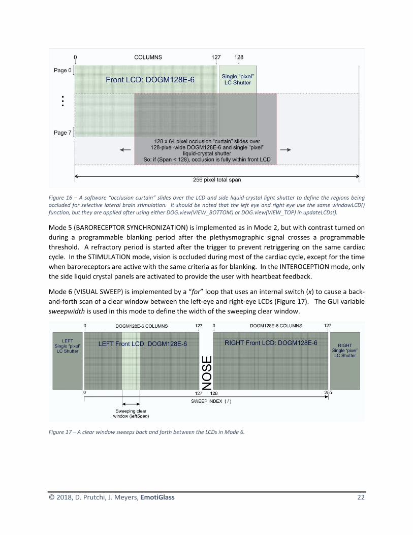
© 2018, D. Prutchi, J. Meyers, EmotiGlass 22
Figure 16 – A software “occlusion curtain” slides over the LCD and side liquid‐crystal light shutter to define the regions being occluded for selective lateral brain stimulation. It should be noted that the left eye and right eye use the same windowLCD() function, but they are applied after using either DOG.view(VIEW_BOTTOM) or DOG.view(VIEW_TOP) in updateLCDs().
Mode 5 (BARORECEPTOR SYNCHRONIZATION) is implemented as in Mode 2, but with contrast turned on
during a programmable blanking period after the plethysmographic signal crosses a programmable
threshold. A refractory period is started after the trigger to prevent retriggering on the same cardiac
cycle. In the STIMULATION mode, vision is occluded during most of the cardiac cycle, except for the time
when baroreceptors are active with the same criteria as for blanking. In the INTEROCEPTION mode, only
the side liquid crystal panels are activated to provide the user with heartbeat feedback.
Mode 6 (VISUAL SWEEP) is implemented by a “for” loop that uses an internal switch (x) to cause a back‐
and‐forth scan of a clear window between the left‐eye and right‐eye LCDs (Figure 17). The GUI variable
sweepwidth is used in this mode to define the width of the sweeping clear window.
Figure 17 – A clear window sweeps back and forth between the LCDs in Mode 6.

© 2018, D. Prutchi, J. Meyers, EmotiGlass 23
6 GUI Design We developed a BLE GUI for EmotiGlass that runs under the Evothings platform. Evothings Studio is a
development tool for creating mobile applications for IoT applications using web technologies and open‐
source software components.
The operating modes and GUI controls are detailed as follows:
6.1 Initial GUI Screen The initial GUI screen shows a stylized figure of EmotiGlass as seen by the user. Pressing “CONNECT”
establishes the BLE connection. A BLE session must be established before allowing the user to select any
of the modes. If a mode button is pressed without connecting, a message is displayed prompting the user
to connect.
Figure 18 – Wireframe for the initial GUI screen for EmotiGlass. BLE Connection must be established before enabling any of the operating modes.
6.2 Clear This mode causes the LCD panels and side liquid‐crystal shutters in EmotiGlass to be as clear as possible.

© 2018, D. Prutchi, J. Meyers, EmotiGlass 24
Figure 19 – EmotiGlass GUI wireframe for CLEAR mode
6.3 Dark This mode causes EmotiGlass to behave as sunglasses. The optical density is set to maximum.
Figure 20 ‐ EmotiGlass GUI wireframe for DARK mode
6.4 Auto‐Dark This mode causes EmotiGlass to behave as auto‐darkening sunglasses. The optical density of the LCDs
and shutters varies between maximum and minimum as a function of ambient illumination.

© 2018, D. Prutchi, J. Meyers, EmotiGlass 25
Figure 21 ‐ EmotiGlass GUI wireframe for AUTO‐DARK mode
6.5 Lateralized Brain Stimulation In this mode, the EmotiGlass goggles occlude the visual field such that only the parts of the retinas that
innervate the left or right brain are illuminated by the scene. A “curtain” that can be moved laterally is
displayed in front of each eye. The position of the “curtain” in front of each eye can be controlled via the
buttons under the image of EmotiGlass. The contrast of the occluding “curtain” is controlled via the
buttons on the side of the figure representing EmotiGlass.
Figure 22 ‐ EmotiGlass GUI wireframe for LATERALIZED BRAIN STIMULATION mode

© 2018, D. Prutchi, J. Meyers, EmotiGlass 26
6.6 Visual Occlusion Synchronized to Baroreceptor Activation In this mode, the scene is occluded in synchrony with baroreceptor activation. The threshold applied to
the plethysmographic signal picked up from the earlobe is programmable via the arrow buttons on top
and bottom of the line representing threshold. Vision may be occluded by EmotiGlass either when the
the baroreceptors are deemed to be active or not. This is controlled via the toggle button labeled
“BLANK/STIM” (Figure 24). “BLANK” is meant to dampen the emotional response to a scene, while “STIM”
is meant to enhance it. The contrast during the occlusion time is controlled via the buttons on the side of
the figure representing EmotiGlass.
Unobtrusively providing direct heartbeat feedback to the user is implemented by selecting the
“INTEROCEPTION” mode (button under the contrast arrow buttons). This causes the side panels to dim
or lighten (as selected by “BLANK” or “STIM”) in synchrony with the plethysmographic signal.
Figure 23 ‐ EmotiGlass GUI wireframe for BARORECEPTOR‐SYNCHRONIZED BLANKING mode

© 2018, D. Prutchi, J. Meyers, EmotiGlass 27
Figure 24 – Operation of EmotiGlass in the baroreceptor‐synchronized mode in a) BLANK mode and b) STIM mode.
6.7 Visual Sweep In the “Visual Sweep” mode, a clear window of programmable width is displayed in front of each eye. The
width is controlled via two arrow buttons under the figure depicting the left lens of the EmotiGlass
goggles. The sweep frequency is controlled by the arrow buttons under the right lens image. The contrast
of the occluded regions is controlled via the buttons on the side of the figure representing EmotiGlass.
The FULL/STIM toggle button reuses the command for Button 12 because it has the same effect as
pressing the “INTEROCEPTION” button in Mode 5 – i.e. leaves the front LCDs clear, while only activating
the side shutters.
Figure 25 ‐ EmotiGlass GUI wireframe for VISUAL‐SWEEP mode

© 2018, D. Prutchi, J. Meyers, EmotiGlass 28
6.8 GUI Installation and Development A GUI app that runs under Android is available at the project page. To install it, one simply has to open
the file manager on any Android device that supports BLE and install the EmotiGlass.apk.
We have not yet submitted an iOS app to the Apple App Store, but this doesn’t prevent running the
EmotiGlass App on any iOS device without having to jailbreak. To do so, the free CGTek Viewer app needs
to be installed from the App Store, and the GUI loaded through Evothings Studio. By the way, the same
works under Android by downloading Evothings Viewer from the Google Store.
Evothings Studio 2.0 first needs to be installed in the computer used for app development. Windows,
Mac OS X and Linux installers are available for free at: https://evothings.com/download/. A starter guide
is available at: https://evothings.com/doc/starter‐guides/evothings‐studio‐starter‐guide.html.
After installing Evothings Studio, a new project named “EmotiGlass” should be started, and the unzipped
contents of EmotiGlassGUI.zip copied into the project’s directory.
Evothings Studio and the Evothings player then need to be connected. This is done by getting a key and
sharing it with the app as shown in Figure 26. That’s it! The BLE‐enabled device running the client should
be able to control EmotiGlass without any further setup.

© 2018, D. Prutchi, J. Meyers, EmotiGlass 29
Figure 26 – Evothings Studio running on a Windows, Mac, or Linux machine is used to develop and upload the GUI into any Android or iOS device running an Evothings player app (e.g. CGTek Viewer for iOS).
For further developing the app, the GUI’s development files can be modified using a smart editor (e.g.
Visual Studio), and the app will be instantaneously updated into any connected Evothings player.

© 2018, D. Prutchi, J. Meyers, EmotiGlass 30
7 Compliance with Requirements and Final Specifications
7.1 Compliance with Requirements Table 1 below shows the way in which the EmotiGlass wearable prototype complies with the project’s
objectives defined by conceptual requirements in Section 2.1.
Table 1 – EmotiGlass wearable prototype compliance with conceptual requirements
Conceptual Requirements (See Section 2.1)
EmotiGlass Wearable Prototype Outcome / Comments
Hardware
The EmotiGlass device shall be constructed as goggles wearable by an adult user.
EmotiGlass fits comfortably a wide range of adult heads.
Fulfills requirement.
The EmotiGlass device shall incorporate a microcontroller to control its operation such that further development can be done by reprogramming the device with no need for hardware changes.
The Adafruit Feather M0 Bluefruit LE used to control EmotiGlass is based on a NXP 32‐bit Cortex‐M0™ microcontroller
Fulfills requirement
The EmotiGlass device shall incorporate a sensor for detecting the wearer’s heartbeat.
The EmotiGlass device incorporates a Pulse Sensor Amped plethysmography sensor.
Fulfills requirement
The EmotiGlass goggles shall be stand‐alone (with exception of the GUI device) and be fully self‐contained.
The EmotiGlass device incorporates all of its electronics (including battery), sensors, and light shutters into its face‐worn enclosure.
Fulfills requirement
The EmotiGlass goggles shall be controlled via a wireless user interface, preferably one that can run as an app on the user’s smartphone or similar portable device.
The user interface is a GUI running as an app in the user’s BLE‐enabled iOS or Android handheld device.
Fulfills requirement
Hardware selected for the EmotiGlass Device shall be widely available. With the exception of custom PCBs and frame, all electronic components shall be in current production and available in small quantities from easily‐accessible vendors to enable experimenters to replicate the device for personal use.
All components for the EmotiGlass are widely available from multiple distributors. All parts are in current production. Files for the manufacture of PCBs and enclosure are made available online.
Fulfills requirement
Firmware

© 2018, D. Prutchi, J. Meyers, EmotiGlass 31
Conceptual Requirements (See Section 2.1)
EmotiGlass Wearable Prototype Outcome / Comments
The firmware for the EmotiGlass device shall implement the following operating modes: a) Clear b) Dark c) Auto‐Dark d) Lateralized Brain Stimulation e) Occlusion synchronized to Baroreceptor Activation f) Interoceptive Awareness g) Visual Sweep
The EmotiGlass wearable prototype implements the following operating modes: a) Clear b) Dark c) Auto‐Dark d) Lateralized Brain Stimulation e) Occlusion synchronized to Baroreceptor Activation f) Interoceptive Awareness (as part of e, above) g) Visual Sweep
Fulfills requirement
The firmware for the EmotiGlass device shall implement the logic layer for communicating with the wireless user interface, preferably one that can run as an app on the user’s smartphone or similar portable device.
The firmware for EmotiGlass communicates with the iOS or Android control app via BLE.
Fulfills requirement
Firmware shall be written in an easily‐accessible language, and shall use only open‐source modules to enable experimenters to replicate and modify the device for personal use.
The firmware for EmotiGlass is written as an Arduino sketch, making it easy to replicate and modify.
Fulfills requirement
User Interface
The user interface shall be intuitive and easy to use
The user interface is very intuitive and easy to use.
Fulfills requirement
If possible, the user interface shall run as an app on the user’s smartphone or portable device
The user interface is a GUI running as an app in the user’s BLE‐enabled iOS or Android handheld device.
Fulfills requirement
Software for the user interface Firmware shall be written in an easily‐accessible language, and shall use only open‐source modules to enable experimenters to replicate and modify the device for personal use.
The GUI for EmotiGlass is written under Evothings Studio, making it easy to replicate and modify.
Fulfills requirement

© 2018, D. Prutchi, J. Meyers, EmotiGlass 32
7.2 Specifications The final specifications for the EmotiGlass wearable prototype are as follows:
Parameter Specification NotesPhysical Specifications
Dimensions 195 mm W X 57 mm H x 150 mm D
Weight 137 g
Frame Materials Ultimaker green PLA + Taulman 645 nylon
Plethysmography Sensor In contact with skin: Transparent nylon and chrome‐plated steel
Optical Specifications
Front optics (each eye) 128x64 pixel liquid‐crystal shutter backed with 0.01” polycarbonate film for eye protection in case of breakage
Side optics (each eye) Single‐pixel liquid‐crystal shutter backed with 0.01” polycarbonate film for eye protection in case of breakage
AC drive at 500Hz
Front optical window opening (each eye)
44.5 mm x 24.8 mm
Side optical window opening (each eye)
22mm x 29.2 mm
Electrical Specifications
Battery 350mAh LiPo
Recharge 5V micro USB
OFF‐state current consumption 73 μA @3.7V, using Feather M0’s ENABLE pin connected to ground
ON‐state current consumption, not connected to BLE
12.2 mA @3.7V, “CLEAR” mode
ON‐state current consumption, connected to VLE and operating
13.7 – 18.8 mA @3.7V, depending on mode
Operating Modes
Clear LCD panels and side liquid‐crystal shutters as clear as possible
Dark LCD panels and side liquid‐crystal shutters as dark as possible
Auto‐Dark Optical density varies between clear and programmable darkness as a function of ambient light intensity

© 2018, D. Prutchi, J. Meyers, EmotiGlass 33
Parameter Specification NotesLateralized Brain Stimulation LCD panels and side liquid‐
crystal shutters occlude the visual field such that only the parts of the retinas that innervate the left or right brain are illuminated by the scene
BaroSynch Scene is occluded in synchrony with baroreceptor activation. Plethysmographic signal threshold is programmable from GUI. “BLANK/STIM” programmable from GUI: “BLANK” dampens emotional response, “STIM” enhances emotional response. “INTEROCEPTION” mode provides direct heartbeat feedback causing side panels to dim or lighten (as selected by “BLANK” or “STIM”) in synchrony with the plethysmographic signal.
Heartbeat signal detected by optical plethysmographic sensor placed on earlobe
Visual Sweep Clear window of programmable width sweeps back‐and‐forth at rate programmable from GUI.
Interface Specifications
API transport Bluetooth Low Energy (BLE)
GUI Requirements
Platform Android 4.4 KitKat or newer Tested on Samsung Galaxy Tab E Lite 7"; 8 GB Wifi Tablet with Android 4.4 KitKat
8 Further Development and Productizing EmotiGlass The EmotiGlass project was developed as a proof‐of‐concept device. It needs further development and
optimization to be turned into an actual wellness product, as well as a device suitable for conducting
controlled clinical trials. One obvious starting point is replacing the expensive LCDs by custom‐built multi‐
segment panels as shown in Figure 27. These can be produced by the same manufacturers that make
custom LCDs. Although NRE is relatively high, unit price can be suitably low under volume production.
Each vertical segment would be more or less 3.5mm wide, making each front shutter have 16 separately‐
addressable segments (instead of the 8,192 pixels of the current LCD). This has the advantage that faster

© 2018, D. Prutchi, J. Meyers, EmotiGlass 34
refresh rates are possible, making spatio‐temporal sweeps much smoother than the prototype
implementation. In addition, much higher contrast can be achieved than with a small‐pixel LCD.
Figure 27 – Conceptual view of a productized version of EmotiGlass. A custom multi‐segment liquid‐crystal shutter would be used instead of the expensive LCDs for the front lenses.
8.1 Electronics The circuit can stripped to only the absolutely necessary components, eliminating the overhead created
by the connectors and dead PCB areas. A single flexible PCB can then be used as the substrate for the
complete EmotiGlass circuit.
8.2 Enclosure Reducing the volume of the circuitry makes it possible to design a much sleeker frame that can be
produced in volume through an injection‐molding process.
A productized version would need to be more robust then the prototype so that it can be widely used.
This could be accomplished by binding the multi‐segment shutters and side shutters to a transparent
impact‐resistant polycarbonate backing, which would be significantly thicker than the .01” film used in
the prototype

© 2018, D. Prutchi, J. Meyers, EmotiGlass 35
8.3 Firmware Firmware for the EmotiGlass prototype is written to implement basic functionality. There is quite a bit
of optimization that can be done on the code that can lead to reduced component count, current
consumption, display flicker, etc.
8.4 GUI Currently, the GUI sends commands to EmotiGlass without knowing if they were received. A productized
version of EmotiGlass would benefit from establishing a bidirectional BLE link with the GUI app. This would
allow the graphical elements in the GUI to be updated to reflect the actual state of EmotiGlass. In addition,
the plethysmography threshold and blanking period could be displayed on a real‐time graph of the
plethysmography signal.
Another aspect that requires attention for a productized version is Bluetooth pairing. At the moment, the
EmotiGlass prototype accepts commands from any device that establishes a link. One‐to‐one pairing
between an EmotiGlass device and its controller should be implemented as is common with Bluetooth‐
enabled consumer electronics.
8.5 Other A major market for EmotiGlass would be as a device for reducing anxiety. The regulatory process for
making a medical claim is much more complex and would require clinical data to support it. However,
EmotiGlass could be sold as a wellness device without making claims that need to be evaluated by FDA or
other regulatory agencies.
Unlike a medical device, which is intended to be used to diagnose, treat, mitigate or prevent a disease,
“wellness devices” are intended only as an aid for general healthy lifestyle. According to FDA regulations,
wellness devices present a minimal risk to the safety of the user and to others. Examples of wellness
devices are those that don’t make specific reference to diseases or conditions and instead make general
claims. These claims are typically related to weight management and physical fitness, including products
intended for recreational use, relaxation or stress management, mental acuity, self‐esteem, sleep
management, etc. EmotiGlass would thus fit well within the category of a wellness device intended for
relaxation and stress management until therapeutic claims can be made after conducting proper clinical
studies.
9 Licenses Hardware for the EmotiGlass project is licensed under the Creative Commons Attribution‐ShareAlike 4.0
International License. To view a copy of this license, visit http://creativecommons.org/licenses/by‐sa/4.0/
Software for the EmotiGlass project is supplied under the MIT open‐source license.
Permission is hereby granted, free of charge, to any person obtaining a copy of this software and
associated documentation files (the "Software"), to deal in the Software without restriction, including
without limitation the rights to use, copy, modify, merge, publish, distribute, sublicense, and/or sell copies
of the Software, and to permit persons to whom the Software is furnished to do so, subject to the
following conditions:

© 2018, D. Prutchi, J. Meyers, EmotiGlass 36
The above copyright notice and this permission notice shall be included in all copies or substantial portions
of the Software.
THE SOFTWARE IS PROVIDED "AS IS", WITHOUT WARRANTY OF ANY KIND, EXPRESS OR IMPLIED,
INCLUDING BUT NOT LIMITED TO THE WARRANTIES OF MERCHANTABILITY, FITNESS FOR A PARTICULAR
PURPOSE AND NONINFRINGEMENT. IN NO EVENT SHALL THE AUTHORS OR COPYRIGHT HOLDERS BE
LIABLE FOR ANY CLAIM, DAMAGES OR OTHER LIABILITY, WHETHER IN AN ACTION OF CONTRACT, TORT
OR OTHERWISE, ARISING FROM, OUT OF OR IN CONNECTION WITH THE SOFTWARE OR THE USE OR
OTHER DEALINGS IN THE SOFTWARE.
The following licenses apply to libraries that are used by the software that operates EmotiGlass:
The source code for the Arduino environment is covered by the GPL, which requires any modifications to
be open‐sourced under the same license. It does not prevent the sale of derivative software or its inclusion
in commercial products. The following libraries fall under this license:
<Arduino.h>
<string.h>
<SPI.h>
<Wire.h>
The LCD module library <dog_7565R.h> is open‐source released under GNU General Public License version
2 or the GNU Lesser General Public License version 2.1, both as published by the Free Software
Foundation.
The following Adafruit libraries are open source released under the BSD License:
Adafruit BLE:
o "Adafruit_BLE.h"
o "Adafruit_BluefruitLE_SPI.h"
o "Adafruit_BluefruitLE_UART.h"
o "BluefruitConfig.h"
<Adafruit_MCP4725.h>
We are not a patent attorneys and cannot render a “Freedom to Operate” opinion on the EmotiGlass
concept, apparatus, or methods. We expressly disclaim any liability for the infringement of any
intellectual property by the making, using, or selling of devices based on the descriptions provided in this
paper, and suggest that anyone interested in such projects seek proper legal counsel.
10 Disclaimer The EmotiGlass project is presented solely for educational purposes. The authors make no medical or
healthcare claims for the EmotiGlass device. The potential therapeutic applications for EmotiGlass have
not been reviewed by FDA or any other regulatory agency. The authors do not suggest that the circuits
and software presented herein can or should be used in place of or as an adjunct to professional medical
treatment or advice. Sole responsibility for the use of these circuits and/or software or of systems
incorporating these circuits and/or software lies with the reader, who must apply for any and all approvals
and certifications that the law may require for their use.

© 2018, D. Prutchi, J. Meyers, EmotiGlass 37
Furthermore, the safe operation of these circuits requires the use of batteries, and connection to external
signal acquisition/processing/monitoring equipment should be done only through signal isolators with the
proper isolation ratings. Users of these devices must also be aware that flickering may cause seizures in
sensitive individuals.
The authors do not make any representations as to the completeness or the accuracy of the information
contained herein, and disclaim any liability for damages or injuries, whether caused by or arising from the
lack of completeness, inaccuracies of the information, misinterpretations of the directions, misapplication
of the circuits and information, or otherwise. The authors expressly disclaim any implied warranties of
merchantability and of fitness of use for any particular purpose, even if a particular purpose is indicated
in this writing.
References to other manufacturers’ products do not constitute an endorsement of these products, but
are included for the purpose of illustration and clarification. It is not the authors’ intent to make any
technical information and interface data presented in this book to supersede information provided by
individual manufacturers.
The authors disclaim any liability for the infringement of patents by the making, using, or selling of such
equipment or circuitry, and suggest that anyone interested in such commercial projects seek proper legal
counsel.
Finally, the authors are not responsible to the reader or third parties for any claim of special or
consequential damages, in accordance to the previous disclaimer.
11 Acknowledgements We are very grateful to Gregory Leonberg for applying his HTML/JavaScript magic to turn our square‐
button EvoThings GUI into pretty graphics that match our wireframe vision.
12 References 1. Azevedo RT, Garfinkel SN, Critchley HD, Tsakiris M, “Cardiac Afferent Activity Modulates the
Expression of Racial Stereotypes”, Nature Communications, 8: 13854, 2017; DOI:
10.1038/NCOMMS13854. Available online at:
https://www.nature.com/articles/ncomms13854.pdf.
2. Buck R, U.S. Patent No. 6,141,797, “Opaque Goggles Having Openable Window”, November 7,
2000. Available online at:
https://patentimages.storage.googleapis.com/6f/7f/c2/bb86033b169aea/US6141797.pdf
3. Critchley HD, Garfinkel SN, “Interactions Between Visceral Afferent Signaling and Stimulus
Processing”, Frontiers in Neuroscience, 9, 2015; DOI: 10.3389/fnins.2015.00286. Available online
at: https://www.frontiersin.org/articles/10.3389/fnins.2015.00286/full.
4. Critchley HD, “ADIE to Prevent Development of Anxiety Disorders in Autism”, ISRCTN14848787,
2017. https://doi.org/10.1186/ISRCTN14848787
5. Electronic Assembly, DOGM GRAPHIC SERIES 128x64, 3.3V, Datasheet Issue 10.2014. Available
online at: https://www.lcd‐module.com/eng/pdf/grafik/dogm128e.pdf.

© 2018, D. Prutchi, J. Meyers, EmotiGlass 38
6. Electronic Assembly, Arduino meets EA DOG‐Graphic series with ST7565R controller, unknown
year of publication. Available online at: https://www.lcd‐module.com/support/application‐
note/arduino‐meets‐ea‐dog.html
7. Gray MA, Rylander K, Harrison NA, Wallin BG, Critchley HD, “Following One’s Heart: Cardiac
Rhythms Gate Central Initiation of Sympathetic Reflexes”, J. Neurosci, 29(6), 1817–1825, 2009;
DOI:10.1523/JNEUROSCI.3363‐08.2009. Available online at:
http://www.jneurosci.org/content/29/6/1817.
8. Gray MA, Rylander K, Harrison NA, Wallin BG, Critchley HD, “Cardiac Rhythms Gate Central
Initiation of Sympathetic Reflexes”, J Neurosci., 29(6), 1817–1825, 2009;
doi:10.1523/JNEUROSCI.3363‐08.2009
9. Gray MA, Beacher FD, Minati L, Nagai Y, Kemp AH, Harrison NA, Critchley H, “Emotional Appraisal
Is Influenced by Cardiac Afferent Information”, Emotion D., 2011; DOI: 10.1037/a0025083
10. Schaefer M, Egloff B, Gerlach AL, Witthöft M, “Improving heartbeat perception in patients with
medically unexplained symptoms reduces symptom distress”, Biol Psychol., 101, 69‐76, 2014;
DOI: 10.1016/j.biopsycho.2014.05.012.
11. Schiffer F, Of Two Minds: The Revolutionary Science of Dual‐Brain Psychology, Free Press, 1998
12. Schiffer F, U.S. Patent No. 5,963,294, “Method for using therapeutic glasses for stimulating a
change in the psychological state of a subject”, October 5, 1999. Available online at:
https://patentimages.storage.googleapis.com/2f/6c/60/8d6cedc5f07f36/US5963294.pdf
13. Shapiro F, Eye Movement Desensitization and Reprocessing (EMDR) Therapy, Third Edition: Basic
Principles, Protocols, and Procedures, The Guilford Press; Third Edition, 2017.

1
1
2
2
3
3
4
4
D D
C C
B B
A A
1 4
Right Side PCB
right side.SchDoc
Title:
File: Sheet of
1.1Rev:
A20181007Date:
Designed By: David Prutchi, Jason MeyersEmotiGlass PrototypeProject:
Size:
VDDSCKSDI
GND/RESET1
3V32
AREF3
GND4
A05
A16
A27
A38
A49
A510
SCK11
MOSI12
MISO13
D014
D115
DFU16 SDA 17SCL 18D5 19D6 20D9 21D10 22D11 23D12 24D13 25VBUS 26EN 27VBAT 28
U10
Feather M0 BLE Stack Connector
VDD
SCKSDI
/CSL
/CSR
SBLSAL
SBRSAR
PTO
GNDVBAT
123
P13
Header 3 A0
Pulse Sensor
GNDPVDDPulse
Pulse
/CSL
/CSR
SBLSAL
SBRSAR
PTO
RSTEN
RSTEN
GND
LED
SCLSDA
PVDD
A0
VBATGND
JST Connector tail for Battery - Watch Polarity
250ma slow
F30
31
2
S1
SW-SPDT
123456
P10
Header 6
123
P11
Header 3
1234
P12
Header 4
12
P14
Header 2 Pin
This work is licensed under the Creative Commons Attribution-ShareAlike 4.0 International License. To view a copy of this license, visit http://creativecommons.org/licenses/by-sa/4.0/.
IO Assignment changes from Breadboard:PVDD MovedA1-4 RemovedSAL-SBR addedPIF3001 PIF3002
COF30
PIP1001
PIP1002
PIP1003
PIP1004
PIP1005
PIP1006
COP10
PIP1101
PIP1102
PIP1103
COP11
PIP1201
PIP1202
PIP1203
PIP1204
COP12
PIP1301
PIP1302
PIP1303
COP13
PIP1401
PIP1402
COP14
PIS101
PIS102
PIS103
COS1
PIU1001
PIU1002
PIU1003
PIU1004
PIU1005
PIU1006
PIU1007
PIU1008
PIU1009
PIU10010
PIU10011
PIU10012
PIU10013
PIU10014
PIU10015
PIU10016 PIU10017
PIU10018
PIU10019
PIU10020
PIU10021
PIU10022
PIU10023
PIU10024
PIU10025
PIU10026
PIU10027
PIU10028
COU10
PIP1101
PIU10024 NL0CSL
PIP1201
PIU10022 NL0CSR
PIP1005
PIU10021 NLA0
PIS103
PIU10027
NLEN
PIP1001 PIP1301
PIP1401
PIS102
PIU1004
NLGND
PIU10026
PIU10025
PIU10023
PIU10020
PIU10018
PIU10017 PIU10016
PIU10013
PIU1007
PIU1003
PIU1001
PIS101
PIF3001 PIP1402
PIP1204
PIU10010 NLPTO
PIP1303
PIU1005
NLPulse PIP1302
PIU1006
NLPVDD
PIP1006
PIU10019 NLRST
PIP1102
PIU1008 NLSAL
PIP1202
PIU10014 NLSAR
PIP1103
PIU1009 NLSBL
PIP1203
PIU10015 NLSBR
PIP1003
PIU10011 NLSCK
PIP1004
PIU10012 NLSDI
PIF3002
PIU10028
NLVBAT
PIP1002
PIU1002 NLVDD

1
1
2
2
3
3
4
4
D D
C C
B B
A A
2 4
Right Front PCB
right front.SchDoc
Title:
File: Sheet of
1.1Rev:
A20181007Date:
Designed By: David Prutchi, Jason MeyersEmotiGlass PrototypeProject:
Size:
V021 V122 V223 V324 V425 VSS26 CAP2N27 CAP2P28 CAP1P29 CAP1N30 CAP3P31 VOUT32 VSS33 VDD234 VDD35 SI36 SCL37 A038 RST39 CS1B40
DS20
EA DOGM128E-6 (No Backlight)
/CSR
A0SCKSDI
Q20ALS PT-19
10kR20
PTO
VDD
GND
VDDSCKSDI
GNDVDDSCKSDI
GND
A0A0
1uC26
1uC25
1uC24
1uC23
1uC22
1uC29
1uC28
1uC27
GND
1uC21
1uC20
VDD
GND
VDDRST
/CSRPTO
RST
RST 123456
P21
Header 6
12345678
P20
Header 8
This work is licensed under the Creative Commons Attribution-ShareAlike 4.0 International License. To view a copy of this license, visit http://creativecommons.org/licenses/by-sa/4.0/.
PIC2001
PIC2002 COC20
PIC2101
PIC2102 COC21
PIC2201
PIC2202 COC22
PIC2301
PIC2302 COC23
PIC2401
PIC2402 COC24
PIC2501
PIC2502 COC25
PIC2601
PIC2602 COC26
PIC2701
PIC2702 COC27
PIC2801
PIC2802 COC28
PIC2901
PIC2902 COC29
PIDS20021
PIDS20022
PIDS20023
PIDS20024
PIDS20025
PIDS20026
PIDS20027
PIDS20028
PIDS20029
PIDS20030
PIDS20031
PIDS20032
PIDS20033
PIDS20034
PIDS20035
PIDS20036
PIDS20037
PIDS20038
PIDS20039
PIDS20040
CODS20
PIP2001
PIP2002
PIP2003
PIP2004
PIP2005
PIP2006
PIP2007
PIP2008
COP20
PIP2101
PIP2102
PIP2103
PIP2104
PIP2105
PIP2106
COP21
PIQ2001
PIQ2002
COQ20
PIR2001
PIR2002 COR20
PIDS20040
PIP2007 NL0CSR
PIDS20038
PIP2005 PIP2105 NLA0
PIC2001 PIC2101
PIC2501 PIC2601 PIC2701 PIC2801 PIC2901
PIDS20026
PIDS20033
PIP2001 PIP2101
PIR2001
NLGND
PIC2102
PIDS20032 PIC2201 PIC2302
PIDS20030
PIC2202
PIDS20031
PIC2301 PIDS20029
PIC2401 PIDS20027
PIC2402 PIDS20028
PIC2502
PIDS20025
PIC2602
PIDS20024
PIC2702
PIDS20023
PIC2802 PIDS20022
PIC2902 PIDS20021
PIP2008
PIQ2002 PIR2002
NLPTO
PIDS20039
PIP2006 PIP2106 NLRST
PIDS20037 PIP2003 PIP2103 NLSCK
PIDS20036 PIP2004 PIP2104 NLSDI PIC2002
PIDS20034
PIDS20035
PIP2002 PIP2102
PIQ2001 NLVDD

1
1
2
2
3
3
4
4
D D
C C
B B
A A
3 4
Left Front PCB
left front.SchDoc
Title:
File: Sheet of
1.1Rev:
A20180107Date:
Designed By: David Prutchi, Jason MeyersEmotiGlass PrototypeProject:
Size:
1uC36
V021 V122 V223 V324 V425 VSS26 CAP2N27 CAP2P28 CAP1P29 CAP1N30 CAP3P31 VOUT32 VSS33 VDD234 VDD35 SI36 SCL37 A038 RST39 CS1B40
DS30
EA DOGM128E-6 (No Backlight)1uC35
1uC34
1uC33
1uC32
1uC39
1uC38
1uC37
GND
1uC31
1uC30
VDD
/CSL
A0SCKSDI
VDDSCKSDI
GND
A0GND
VDD
/CSL
RST
RST
1234567
P30
Header 7
This work is licensed under the Creative Commons Attribution-ShareAlike 4.0 International License. To view a copy of this license, visit http://creativecommons.org/licenses/by-sa/4.0/.
PIC3001
PIC3002 COC30
PIC3101
PIC3102 COC31
PIC3201
PIC3202 COC32
PIC3301
PIC3302 COC33
PIC3401
PIC3402 COC34
PIC3501
PIC3502 COC35
PIC3601
PIC3602 COC36
PIC3701
PIC3702 COC37
PIC3801
PIC3802 COC38
PIC3901
PIC3902 COC39
PIDS30021
PIDS30022
PIDS30023
PIDS30024
PIDS30025
PIDS30026
PIDS30027
PIDS30028
PIDS30029
PIDS30030
PIDS30031
PIDS30032
PIDS30033
PIDS30034
PIDS30035
PIDS30036
PIDS30037
PIDS30038
PIDS30039
PIDS30040
CODS30
PIP3001
PIP3002
PIP3003
PIP3004
PIP3005
PIP3006
PIP3007
COP30
PIDS30040
PIP3007 NL0CSL
PIDS30038
PIP3005 NLA0
PIC3001 PIC3101
PIC3501 PIC3601 PIC3701 PIC3801 PIC3901
PIDS30026
PIDS30033
PIP3001 NLGND PIC3102
PIDS30032 PIC3201 PIC3302
PIDS30030
PIC3202
PIDS30031
PIC3301 PIDS30029
PIC3401 PIDS30027
PIC3402 PIDS30028
PIC3502
PIDS30025
PIC3602
PIDS30024
PIC3702
PIDS30023
PIC3802 PIDS30022
PIC3902 PIDS30021
PIDS30039
PIP3006 NLRST
PIDS30037
PIP3003 NLSCK
PIDS30036
PIP3004 NLSDI
PIC3002
PIDS30034
PIDS30035 PIP3002 NLVDD

1
1
2
2
3
3
4
4
D D
C C
B B
A A
4 4
Right Side Development PCB
right side dev.SchDoc
Title:
File: Sheet of
1.2Rev:
A20181016Date:
Designed By: David Prutchi, Jason MeyersEmotiGlass PrototypeProject:
Size:
/RESET1
3V32
AREF3
GND4
A05
A16
A27
A38
A49
A510
SCK11
MOSI12
MISO13
D014
D115
DFU16 SDA 17SCL 18D5 19D6 20D9 21D10 22D11 23D12 24D13 25VBUS 26EN 27VBAT 28
U6
Feather M0 BLE
VDD
SBRSAR
GND
SBL
22kR1
.01uC1
VOUT 1
A06
VSS 2
SDA4 SCL5
VDD3
U2
MCP4725A1T-E/CHVDD
VDD
SCLSDA
GND
GND
VOUT 1
A06
VSS 2
SDA4 SCL5
VDD3
U4
MCP4725A1T-E/CH
VDD
SCLSDA
PH1 PH2
PH1PH2
SAL
VDDGND
PH1PH2
SBR
GND
SAR
Liquid Crystal Shutter Drivers GND
.1uC5
VDD
.1uC6
.1uC7
.1uC8
.1uC9
SCLSDA
SBLSAL
IN11
D1 2S13
VSS 4
GND 5
S46 D4 7
IN48 IN39
D3 10S311
NC 12
VDD13
S214 D2 15
IN216
U1
MAX392
IN11
D1 2S13
VSS 4
GND 5
S46 D4 7
IN48 IN39
D3 10S311
NC 12
VDD13
S214 D2 15
IN216
U3
MAX392
21
U5A
CD40106BM
43
U5B
CD40106BM
65
U5C
CD40106BM
89
U5D
CD40106BM
1011
U5E
CD40106BM
1213
U5F
CD40106BM
VD
D14
VSS
7
U5GCD40106BM
10kR3
10kR4
GND
VDD
100k
31
2 R2
This work is licensed under the Creative Commons Attribution-ShareAlike 4.0 International License. To view a copy of this license, visit http://creativecommons.org/licenses/by-sa/4.0/.
A3,A4,D0,D1 must be set as inputs when HW shutter drive is used
PIC101
PIC102 COC1
PIC501
PIC502 COC5
PIC601
PIC602 COC6
PIC701
PIC702 COC7
PIC801
PIC802 COC8
PIC901
PIC902 COC9
PIR101
PIR102 COR1
PIR201 PIR202
PIR203
COR2
PIR301
PIR302 COR3
PIR401
PIR402 COR4
PIU101
PIU102 PIU103
PIU104
PIU105
PIU106 PIU107
PIU108
PIU109
PIU1010 PIU1011
PIU1012
PIU1013
PIU1014 PIU1015
PIU1016
COU1
PIU201
PIU202 PIU203
PIU204
PIU205
PIU206
COU2
PIU301
PIU302 PIU303
PIU304
PIU305
PIU306 PIU307
PIU308
PIU309
PIU3010 PIU3011
PIU3012
PIU3013
PIU3014 PIU3015
PIU3016
COU3
PIU401
PIU402 PIU403
PIU404
PIU405
PIU406
COU4
PIU501 PIU502
COU5A
PIU503 PIU504
COU5B
PIU505 PIU506
COU5C
PIU508 PIU509
COU5D
PIU5010 PIU5011
COU5E
PIU5012 PIU5013
COU5F
PIU507
PIU5014 COU5G
PIU601
PIU602
PIU603
PIU604
PIU605
PIU606
PIU607
PIU608
PIU609
PIU6010
PIU6011
PIU6012
PIU6013
PIU6014
PIU6015
PIU6016 PIU6017
PIU6018
PIU6019
PIU6020
PIU6021
PIU6022
PIU6023
PIU6024
PIU6025
PIU6026
PIU6027
PIU6028
COU6
PIC501 PIC601 PIC701 PIC801 PIC901
PIU103
PIU104
PIU105
PIU1014
PIU202
PIU206
PIU303
PIU304
PIU305
PIU3014
PIU402
PIU507 PIU5013
PIU604
NLGND PIU6028
PIU6027
PIU6026
PIU6025
PIU6024
PIU6023
PIU6022
PIU6021
PIU6020
PIU6019
PIU6016
PIU6013
PIU6012
PIU6011
PIU6010
PIU607
PIU606
PIU605
PIU603
PIU601
PIU5011 PIU5012 PIU5010
PIU3012
PIU306
PIU3011 PIU401
PIU1012
PIU106
PIU1011 PIU201
PIR102 PIU502 PIU503
PIR101 PIR201
PIC102
PIU504 PIU505
PIC101 PIR202
PIR203
PIU501
PIU108
PIU1016
PIU308
PIU3016
PIU506 PIU509
NLPH1
PIU101
PIU109
PIU301
PIU309
PIU508
NLPH2
PIU102
PIU107
PIU608
NLSAL
PIU302
PIU307
PIU6014
NLSAR
PIU1010
PIU1015
PIU609
NLSBL
PIU3010
PIU3015
PIU6015
NLSBR PIR401
PIU205
PIU405
PIU6018
NLSCL
PIR301
PIU204
PIU404
PIU6017
NLSDA
PIC502 PIC602 PIC702 PIC802 PIC902
PIR302 PIR402
PIU1013
PIU203
PIU3013
PIU403
PIU406
PIU5014
PIU602
NLVDD

U5
C1R2
U5 C6R1C5 U3
R4
R3
C7
C8
U1 C9
U4
U2
EmotiGlass RSD1.1 DP JRM
P1
2P
11P14
P1
0
EmotiGlass RS1.1 DP JRM
LF1.1 P JRMD
EmotiGlassEmotiGlass
RF1.1DP JRM
Right Side (Actual Size)
Right Front (Actual Size) Left Front (Actual Size)
Right Side Dev (Actual Size)
P1
2P
11P1
4
P1
0
EmotiGlass RS1.1 DP JRM
PCB Prints and Assembly NotesEmotiGlass Prototype Revision 1.1 Jason Meyers, David Prutchi 20181009
PCBs here are shown looking at outside of glasses (wearer is looking at you). Left and Right are as worn. Through hole components on top layer (red) unless noted.
EmotiGlass
RF1.1DP JRM
LF1.1 P JRMD
EmotiGlassU5
C1R2
U5 C6R1C5 U3
R4
R3
C7
C8
U1 C9
U4
U2
EmotiGlass RSD1.1 DP JRM
Install stack connector on bottom.
Right Front
Left Front
Shorten leads on stack connectorpins 11-14 so that they sit flush aftersoldering. Mount P3 to bottom of board.
Unlabeled footprints are C30-C39. Display mounts to bottom.
Q20 dot indicates collector. Unlabeled footprints are C20-C29. Display mounts to bottom.
Q20 R20Right Side Dev
Right Side
P3
This work is licensed under the Creative Commons Attribution-ShareAlike 4.0 International License. To view a copy of this license, visit http://creativecommons.org/licenses/by-sa/4.0/.
F30

PCB Wire to Board Header PinoutsEmotiGlass Prototype Revision 1.2 Jason Meyers, David Prutchi 20181017
PCBs here are shown looking at outside of glasses (wearer is looking at you). Left and Right are as worn.
Wire wrap wire (30AWG) with kynar or teflon insulation is recommended for connections. Battery connections and ground wiring should either be doubled or use 26 AWG wire.
All signals are wired from the Right Side PCB directly to their corresponding header or attachment point, with the exception of pins 1-6 of P30 which are wired to P21. Battery pigtail ground should be wired to P14.
Right Front Left Front
PV
DD
Pu
lse
P1
2 SAR
/CSR
SAL
/CSL A0
SBR
PTO
SBL
GN
D
P11
P1
0
GND
VDD
SCK
SDI
RST
P13
On
P1
2P
11P1
4
P1
0
GND
Bat+
P1
4
EmotiGlass
VD
D
A0
A0
SC
K
SD
I
PT
O
RS
T
/CS
R
SC
K
SD
I
RS
T
VD
D
GN
D
P20 P21
GN
D
Right Side
SD
I
A0
SC
K
RS
T
/CS
L
GN
D
VD
D
P30
Left Side Shutter
SAL SBL
Right Side Shutter
SAR SBR
This work is licensed under the Creative Commons Attribution-ShareAlike 4.0 International License. To view a copy of this license, visit http://creativecommons.org/licenses/by-sa/4.0/.
Puls
eP
VD
DG
nd
Pulse Sensor
Bat+GND
Battery Pigtail

Emotiglass Bill of MaterialsRevision 1.2 20181016
David Prutchi, Jason Meyers
Electronic Components
Standalone ComponentsQuantity Comment Value MFGR MFGR PN Digikey PN
1 Feather M0 BLE Adafruit 2995 1528‐1562‐ND
28 pos Feather Stack Connector Mill‐Max 311‐93‐164‐41‐001000 ED1064‐ND
2 LCD Shutter Adafruit 3627 1528‐2516‐ND
1 Pulse Sensor Pulsesensor.com Pulsesensor 1568‐1247‐ND
1 Pulse Sensor Connector Harwin M20‐1060300 952‐2228‐ND
1 Lipo Battery 350mAh Adafruit 2750 1528‐1858‐ND
1 JST‐PH male connector JST 455‐1704‐ND B2B‐PH‐K‐S(LF)(SN)
Right Side PCB AssemblyQuantity Designator Comment Value Asm type MFGR MFGR PN Digikey PN
1 Right Side PCB (unpopulated)
1 F30 Fuse 375ma SMD AVX Corporation F0603E0R37FSTR 478‐2859‐1‐ND
1 S1 SW‐SPDT CSS‐1210MC TH copal CSS‐1210MC 563‐1090‐ND
1 P13 Header 3 TH M20‐7890346 952‐1782‐ND
28 pos U10 Feather M0 BLE Stack Connector TH Mill‐Max 801‐93‐064‐10‐002000 ED10964‐64‐ND
0 P10, P11, P12, P14 Header ‐ direct wire dnp
Right Front PCB AssemblyQuantity Designator Comment Value Asm type MFGR MFGR PN Digikey PN
1 Right Front PCB (unpopulated)
10
C20, C21, C22, C23, C24,
C25, C26, C27, C28, C29 C 1u SMD Murata GRT188R61E105KE13D 490‐12321‐1‐ND
1 R20 R 10k SMD Panasonic ERJ‐3EKF1002V P10.0KHTR‐ND
1 Q20 ALS PT‐19 ALS PT‐19 SMD Everlight ALS‐PT19‐315C/L177/TR8 1080‐1244‐1‐ND
1 DS20 EA DOGM128E‐6 (No Backlight) EA DOGM128E‐6 TH EA EA DOGM128E‐6 1481‐1065‐ND
0 P20,P21 Header ‐ direct wire dnp
Left Front PCB AssemblyQuantity Designator Comment Value Asm type MFGR MFGR PN Digikey PN
1 Left Front PCB (unpopulated)
10
C30, C31, C32, C33, C34,
C35, C36, C37, C38, C39 C 1u SMD Murata GRT188R61E105KE13D 490‐12321‐1‐ND
1 DS30 EA DOGM128E‐6 (No Backlight) EA DOGM128E‐6 TH EA EA DOGM128E‐6 1481‐1065‐ND
0 P30 Header ‐ direct wire dnp
Right Side Dev PCB AssemblyQuantity Designator Comment Value Asm type MFGR MFGR PN Digikey PN
1 Right Side Dev PCB (unpopulated)
1 C1 C .01u SMD Murata GRM188R71H103KA01D 490‐1512‐1‐ND
5 C5, C6, C7, C8, C9 C .1u SMD Murata GRM188R71H104KA93D 490‐1519‐1‐ND
1 R1 R 22k SMD Panasonic ERJ‐3EKF2202V P22.0KHCT‐ND
2 R3, R4 R 10k SMD Panasonic ERJ‐3EKF1002V P10.0KHCT‐ND
1 R2 RPot 100k SMD Copal ST4ETB104 ST4ETB104CT‐ND
2 U1, U3 MAX392 MAX392 SMD Maxim MAX392CSE+ MAX392CSE+‐ND
2 U2, U4 MCP4725A0T‐E/CH MCP4725A1T‐E/CH SMD Microchip MCP4725A1T‐E/CH MCP4725A1T‐E/CHCT‐ND
1 U5 CD40106BM CD40106BM SMD Texas Instruments CD40106BM96 296‐14081‐1‐ND
28 pos U6 Feather M0 BLE Stack Connector Mill‐Max 350‐10‐164‐00‐001000 ED3864‐64‐ND

Mechanical ComponentsQuantity Part Mcmaster Part # Substitute Option
10 Screw, 2‐56x1/4" 91772A077 M2x6
2 Screw, 2‐56x7/8" 91772A085 M2x22
2 pieces Polycarbonate film, .01" 85585K103
3D Printed PartsQuantity Part
1 Frame
1 Left Side
1 Right Side
1 Key
6 Spacer
SuppliesQuantity Supply Details
Wire, 30 awg wire wrap Red, black, and one other color
Heatshrink tubing 1/16" and 1/4"
Kapton Tape 1/4"
This work is licensed under the Creative Commons Attribution‐ShareAlike 4.0 International License.
To view a copy of this license, visit http://creativecommons.org/licenses/by‐sa/4.0/.
EmotiGlass Build Intructions Jason Meyers, David Prutchi
Revision: 1.0 20181017
Documents Referenced • Bill of Materials Rev 1.2
o Contains listing of all components needed to build one EmotiGlass prototype
• PCB Drawings and Assembly Notes Rev 1.1 o Contains diagrams and notes needed to assemble
the EmotiGlass PCBs • Wiring Info 1.2
o Contains pinouts needed to wire together all components of the EmotiGlass prototype
This document contains instructions to build an EmotiGlass wearable prototype. Photos of most steps are included. Please gather the documents referenced above before proceeding.
All files and documentation can be found at https://hackaday.io/project/160615-emotiglass
Steps Collect and Prepare Components .................................................. 2
Order electronic components .................................................... 2
Order PCBs ................................................................................. 2
Gather tools and supplies .......................................................... 3
Assemble PCBs ........................................................................... 3
3D Print frame components ....................................................... 4
Install Firmware and GUI ............................................................... 5
Install Firmware ......................................................................... 5
Install GUI ................................................................................... 6
Wearable Prototype Assembly ...................................................... 7
Pre-assemble Frame................................................................... 7
Prepare Front Displays ............................................................... 8
Complete front PCB assembly .................................................... 9
Pre-wiring ................................................................................... 9
Install components in frame .................................................... 10
Wiring ....................................................................................... 11
Complete frame ....................................................................... 13
PCB Stack assembly .................................................................. 13
Power on .................................................................................. 14
Assemble Pulse Sensor ............................................................. 16
Complete EmotiGlass ............................................................... 17

Collect and Prepare Components
Order electronic components All electronic components used are readily available from a number of retailers. For convenience, the BOM includes DigiKey part numbers – all components were in stock at the time of writing. Passive component values are not critical, so similar parts may be substituted.
Order PCBs The PCBs were designed to be fabricated on a standard 1/16” (1.6mm) 2-layer process and were designed to meet typical design rules. They can be ordered from Osh Park or most other PCB fabricators. A zip file containing the Gerbers can be found on the project page. This file contains 4 zip files, each of which may be directly uploaded to the fabricator.

Gather tools and supplies In addition to the components, some tools and supplies will be needed. These include:
• Safety Equipment o Safety glasses
• Supplies o Wire wrap wire (red, black, and one additional color
preferably) 30AWG with Kynar (PVDF) insulation is
recommended (ex. DigiKey K394-ND) o Heatshrink – 1/16” for wires and (optional) 1/4” for o Kapton tape
Used to fix damaged wire insulation and for temporarily holding components
o Hot Glue • General assembly tools
o Pliers, o Tweezers o Screwdrivers
Small Philips and flat head o Dental pick, wire director, or similar o Scissors
• Electronic assembly tools and supplies o Wire cutters and strippers o Soldering iron o Solder, flux, flux remover, solder wick o Solder paste (optional)
• 3D Print finishing tools o Xacto knife o Flush cutters o Sandpaper (180-320 grit works best)
Assemble PCBs Refer to the “PCB Drawings and Assembly Notes” document for the details needed to assemble the PCBs. Components can be mounted using a standard soldering iron. If available, solder paste and a reflow oven may speed the process. The displays should not be mounted to the front left and front right PCBs until later in the process, but all other components should be installed. Photo below shows the assembled boards.

3D Print frame components There are 5 unique 3D Printed parts in the EmotiGlass design. Most filament extrusion-type 3D printers with a common .4mm nozzle should be able to print these without issue.
The frame is the largest piece, and should be printed from a stiff material such as PLA so that it can protect the glass components. The prototype in the pictures was printed in green Ultimaker PLA on an Ultimaker 2+. It is necessary to print with support material, and we suggest using a .4mm nozzle so that the support material can reasonably be removed. The prototype shown used .15mm layers, which work well for this part, although .1mm will give slightly smoother curves if print time is not critical.
The two side pieces should be printed from a less stiff plastic. The prototype shown used Taulman 645 nylon printed by a Cetus MK2, using a .4mm nozzle and .15mm layers. Other nylons or comparable materials should also work. Note that nylon must be dried before use for good print results.
The key and spacers can be printed from any convenient material. The ones shown below were printed in the same batch as the side pieces. I suggest printing extra spacers as they are tiny and easily lost.

The next step is to remove support material, strings, and brims/rafts from the printed parts. All of the parts other than the frame will require minimal cleanup. The frame will have a rough surface on the bottom curves, which can be cleaned up with a knife and some sandpaper. It is critical to remove all support material from the display grooves to prevent assembly problems.
Install Firmware and GUI In order to test and control the EmotiGlass prototype, the Adafruit Feather will need to have the firmware installed, and the GUI will need to be installed on a phone or tablet. The firmware must be installed on the Feather before final electronic assembly.
Install Firmware Firmware for EmotiGlass is loaded via the Arduino IDE. Besides the standard libraries available to the Arduino v1.8.2 IDE, support libraries for the Adafruit Feather M0 Bluefruit LE need to be installed. Detailed instructions are available at: https://cdn-learn.adafruit.com/downloads/pdf/adafruit-feather-m0-bluefruit-le.pdf
The driver library for the LCDs also needs to be installed. Download and unzip the package from: https://www.lcd-module.com/fileadmin/downloads/development%20service/Arduino/Arduino%20meets%20EA%20DOGM132-5%20DOGM128-6%20DOGL128-6.zip. After that, follow the instructions available at: Arduino meets EA DOGM132-5 DOGM128-6 DOGL128-6\Documentation\ReadMe.pdf.
After that, install the source files for EmotiGlass from https://hackaday.io/project/160615-emotiglass) and compile/verify. Make sure that the board selected under the Arduino IDE’s “Tools” is “Adafruit Feather M0.” Select the serial port assigned to your board and upload the compiled firmware.

Install GUI The GUI files may be downloaded from the project page. For Android only, a compiled application may be installed. For Android or iOS, the GUI may be installed via Evothings Studio
Android App Install
Open the file manager on any Android device that supports BLE and install the EmotiGlass.apk.
Evothings Studio PC Install Evothings Studio 2.0 needs to be installed on a computer used if using an iOS device or developing the APP. Windows, Mac OS X and Linux installers are available for free at: https://evothings.com/download/. A starter guide is available at: https://evothings.com/doc/starter-guides/evothings-studio-starter-guide.html.
After installing Evothings Studio, a new project named “EmotiGlass” should be started, and the unzipped contents of EmotiGlassGUI.zip copied into the project’s directory.
Evothings Studio and the Evothings player then need to be connected. This is done by getting a key and sharing it with the app as shown in the following imade. The BLE-enabled device running the client should be able to control EmotiGlass without any further setup.
Evothings Studio iOS Install Install the free CGTek Viewer app from the App Store, and load the GUI through Evothings Studio.
Evothings Studio Android Install Download and install Evothings Viewer from the Google Store

Wearable Prototype Assembly Pre-assemble Frame After the 3D printed parts have been finished, the threads need to be cut for the screws, which should be done before any electronics are installed. In these parts, it is sufficient to simply let the screws cut their own threads when initially installing them. Unless specified, use either #2-56x1/4” or M2x6 screws. Be careful to keep the screws straight during the initial installation. This is also a good time to check the fit of the side pieces into the frame. After this is complete, remove all screws.

Prepare Front Displays Some of the pins on the LCD Displays need to be removed (pins 1-3 and 18-20). These pins were installed by the manufacturer by crimping them onto the base glass and then putting some potting compound over them. To remove, they can be bent away from the display and then any excess potting compound can be scraped off. A wire cutter can be used for this. One of the cutting edges is inserted under edge of the metal pin, and the cutter is closed only enough to keep it in place as the cutter is rotated to bend the pin away from the glass. Be careful!
After the displays have had the bottom pins removed, cut pieces of polycarbonate film to match the size of these displays. Also cut pieces to match the side LCD shutters (not shown in photo). This film is intended to provide extra protection to the wearer in case the displays are somehow broken while the device is being worn.

Complete front PCB assembly Next, install the displays and the polycarbonate film into the frame. The film should be on the inside (wearer side) of the displays. The front PCBs can then be installed and screwed into place. Once the front PCBs are secured, the display can be soldered into the board. The spacing between the PCB and display is critical, so it must be assembled in place. Once the displays are soldered to the PCBs, remove the complete assemblies from the frame.
Pre-wiring Next, attach wires to the side shutters and to the headers which send wires towards the right side (P20 and P30). The wires should exit the rear of the PCBs as shown. Be sure that the insulation comes close enough to the boards to prevent shorts. You may want to put some Kapton tape on the connections for the side shutters. The battery pigtail can also be assembled at this time by attaching wires to the male JST connector. Be sure to leave a lot of extra length on the wires. The battery connections and board to board ground connections should be doubled or use thicker wire. The battery pigtail should be twisted together.

Install components in frame The battery should be installed with the lead proceeding up the channel provided in the frame. Install the left side piece, being careful not to pinch the battery wire. The pigtail can also be routed down this channel to place the connection point in front of the battery. Do not plug in the battery yet. (Note: the frame was designed for the battery to be hard wired, but we are leaving it connectorized until thorough testing is complete so we can easily unplug it if we have any issues.)
The side shutters now can be installed. The protective film on the shutters and on the polycarbonate film will need to be removed before they are installed. Be sure to clean the faces of the shutter and film that touch each other as they will not be accessible after assembly. It is helpful to use a screwdriver to pull the edge of the frame locking tabs forward slightly during the installation.
The right side PCB can also be installed. It should be installed with 3 screws as shown. Once wiring begins, this PCB should not ever be removed from the frame. The frame provides access for wiring when the right side piece is not installed.

The front displays should be installed, but should remain slightly above their nominal positions. They can be rested on a screw placed in one of the mounting holes (this can be tightened to hold these PCBs in place if needed)
Wiring Begin wiring by making the connections between the two front PCBs. Reference the wiring info diagram for connection info.

Once these connections are complete, the front PCBs may be dropped into their final positions and secured with their mounting screws. Next, dressing of the wires can begin. A number of holes are provided thorough which a tie can be installed. The prototype used offcuts of wire wrap wire for the ties, but thread of twine would probably work even better. Starting from the end with the battery, dress the wires into the groove and secure. A tool such as a wire director or dental pick or similar (a bent tiny screwdriver could also work) is extremely helpful for manipulating the wires. We suggest not tying around all wires, but rather letting some wires remain below the tied bundle and only tying around the battery lead and a few additional wires as needed.
Finish the wiring by trimming all of the wires and soldering them into the headers in the right side PCB. After that, finish dressing the wires.

Complete frame Next, the right side piece can be installed. Be careful not to pinch any wires. The right side piece is secured by two screws. After installing the side piece, remove the screws in the top left and bottom right positions.
PCB Stack assembly Before proceeding ensure that:
1. The Feather has been flashed with EmotiGlass firmware
2. The battery is still unplugged

The Right Side Dev PCB stacks onto the Feather, which stacks onto the Right Side PCB. Initially, these can be plugged together for testing. Once complete, 2 #2-56x7/8” secure the stack. 2 of the 3D printed spacers go between the top two boards, and 1 goes between the lower two boards (on each screw).
Power on Before powering on, measure the resistance between the two terminals of the battery connector to ensure there is no short. EmotiGlass can be powered via a USB connection or from the battery (USB power will charge the battery when both are connected). If a current-limited power supply is available, it is best to initially power the device from that. This is a good point to test basic functionality (connect the GUI via Bluetooth and click ‘Dark’ and ‘Clear’). The battery connector can be held to the battery with a piece of tape as shown.
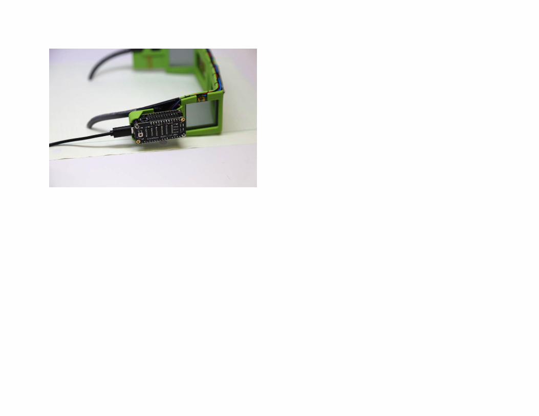

Assemble Pulse Sensor EmotiGlass uses an open-source plethysmography sensor from pulsesensor.com (see site for more information). This sensor can be hot glued to an ear clip, Velcro finger strap, or other mounting arrangement. Following the suggestions of the manufacturer, the sensor is encapsulated in hot glue as part of the mounting.
Lastly, a 3D printed key is added to the connector to prevent the sensor from being inserted backwards, which may damage the circuitry. Remove the three single pin connector housings, and replace with the 3 position connector housing (pins in same order as cable, black is pin 1). Then, with pin 1 (black) to the left, glue the key piece underneath the connector (see photos). The front face of the key should sit flush or slightly behind the front of the connector housing. If you desire to trim the cable and don’t have the crimp on pins available, the wire can be soldered to 3 positions of a standard header strip, which can then be glued to the key. Both options are shown in following photos.
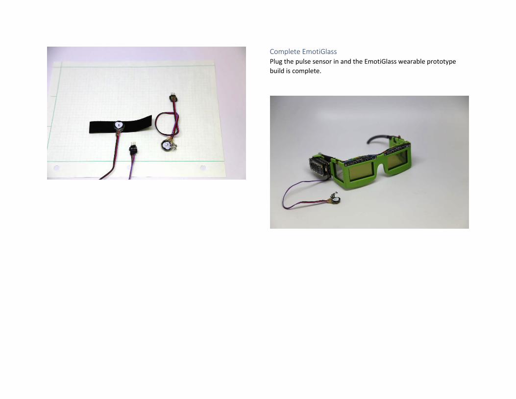
Complete EmotiGlass Plug the pulse sensor in and the EmotiGlass wearable prototype build is complete.