en 302 194 - v2.1.0 - navigation radar used on inland waterways
TRANSCRIPT

Draft ETSI EN 302 194 V2.1.0 (2016-05)
Navigation radar used on inland waterways; Harmonised Standard covering the essential requirements of
article 3.2 of the Directive 2014/53/EU
HARMONISED EUROPEAN STANDARD

ETSI
Draft ETSI EN 302 194 V2.1.0 (2016-05) 2
Reference REN/ERM-TG26-141
Keywords Harmonised standard, maritime, navigation,
radar, radio
ETSI
650 Route des Lucioles F-06921 Sophia Antipolis Cedex - FRANCE
Tel.: +33 4 92 94 42 00 Fax: +33 4 93 65 47 16
Siret N° 348 623 562 00017 - NAF 742 C
Association à but non lucratif enregistrée à la Sous-Préfecture de Grasse (06) N° 7803/88
Important notice
The present document can be downloaded from: http://www.etsi.org/standards-search
The present document may be made available in electronic versions and/or in print. The content of any electronic and/or print versions of the present document shall not be modified without the prior written authorization of ETSI. In case of any
existing or perceived difference in contents between such versions and/or in print, the only prevailing document is the print of the Portable Document Format (PDF) version kept on a specific network drive within ETSI Secretariat.
Users of the present document should be aware that the document may be subject to revision or change of status. Information on the current status of this and other ETSI documents is available at
https://portal.etsi.org/TB/ETSIDeliverableStatus.aspx
If you find errors in the present document, please send your comment to one of the following services: https://portal.etsi.org/People/CommiteeSupportStaff.aspx
Copyright Notification
No part may be reproduced or utilized in any form or by any means, electronic or mechanical, including photocopying and microfilm except as authorized by written permission of ETSI.
The content of the PDF version shall not be modified without the written authorization of ETSI. The copyright and the foregoing restriction extend to reproduction in all media.
© European Telecommunications Standards Institute 2016.
All rights reserved.
DECTTM, PLUGTESTSTM, UMTSTM and the ETSI logo are Trade Marks of ETSI registered for the benefit of its Members. 3GPPTM and LTE™ are Trade Marks of ETSI registered for the benefit of its Members and
of the 3GPP Organizational Partners. GSM® and the GSM logo are Trade Marks registered and owned by the GSM Association.

ETSI
Draft ETSI EN 302 194 V2.1.0 (2016-05) 3
Contents
Intellectual Property Rights ................................................................................................................................ 8
Foreword ............................................................................................................................................................. 8
Modal verbs terminology .................................................................................................................................... 8
1 Scope ........................................................................................................................................................ 9
2 References ................................................................................................................................................ 9
2.1 Normative references ......................................................................................................................................... 9
2.2 Informative references ........................................................................................................................................ 9
3 Definitions, symbols and abbreviations ................................................................................................. 10
3.1 Definitions ........................................................................................................................................................ 10
3.2 Symbols ............................................................................................................................................................ 10
3.3 Abbreviations ................................................................................................................................................... 11
4 General requirements ............................................................................................................................. 11
4.1 Purpose of the radar equipment ........................................................................................................................ 11
4.2 Construction and design ................................................................................................................................... 11
4.3 Operating frequency range ............................................................................................................................... 11
4.4 Operational controls ......................................................................................................................................... 12
4.5 Interfaces .......................................................................................................................................................... 12
4.5.1 Fail safe design ........................................................................................................................................... 12
4.5.2 Display of data received via interfaces ....................................................................................................... 12
4.5.3 Operation of equipments connected via interfaces ..................................................................................... 12
4.5.4 Interpretation and presentation of data delivered via interfaces.................................................................. 12
4.6 Software ........................................................................................................................................................... 13
4.6.1 Software performance ................................................................................................................................. 13
4.6.2 Software protection ..................................................................................................................................... 13
4.7 Equipment labelling ......................................................................................................................................... 13
4.8 Operating and service manuals ......................................................................................................................... 13
5 Testing for compliance with technical requirements .............................................................................. 13
5.1 Environmental conditions for testing ............................................................................................................... 13
5.2 Standard operating mode of the radar equipment ............................................................................................. 14
6 General conditions of tests ..................................................................................................................... 14
6.1 Normal test conditions ...................................................................................................................................... 14
6.1.1 Introduction................................................................................................................................................. 14
6.1.2 Normal temperature and humidity .............................................................................................................. 14
6.1.3 Normal test power supply ........................................................................................................................... 15
6.1.3.1 AC test power supply ............................................................................................................................ 15
6.1.3.2 DC test power supply ............................................................................................................................ 15
6.2 Extreme test conditions .................................................................................................................................... 15
6.2.1 Extreme temperatures ................................................................................................................................. 15
6.2.1.1 Indoor unit ............................................................................................................................................. 15
6.2.1.2 Outdoor unit .......................................................................................................................................... 15
6.2.2 Extreme power supply voltage test conditions ........................................................................................... 15
6.2.3 Extreme vibration test conditions ............................................................................................................... 15
7 Procedures for tests under extreme conditions ....................................................................................... 16
7.1 Performance check procedure .......................................................................................................................... 16
7.1.1 Introduction................................................................................................................................................. 16
7.1.2 Method ........................................................................................................................................................ 16
7.1.3 Required test result ..................................................................................................................................... 16
7.2 Extreme temperature tests ................................................................................................................................ 16
7.2.1 Test of the indoor unit ................................................................................................................................. 16
7.2.1.1 Definition .............................................................................................................................................. 16
7.2.1.2 Test method ........................................................................................................................................... 16
7.2.1.3 Required test result ................................................................................................................................ 16
7.2.2 Test of the outdoor unit ............................................................................................................................... 17

ETSI
Draft ETSI EN 302 194 V2.1.0 (2016-05) 4
7.2.2.1 Definition .............................................................................................................................................. 17
7.2.2.2 Test method ........................................................................................................................................... 17
7.2.2.3 Required test result ................................................................................................................................ 17
7.3 Damp heat test .................................................................................................................................................. 17
7.3.1 Definition .................................................................................................................................................... 17
7.3.2 Test method ................................................................................................................................................ 17
7.3.3 Required test result ..................................................................................................................................... 17
7.4 Extreme power voltage and frequency test ....................................................................................................... 18
7.4.1 Definition .................................................................................................................................................... 18
7.4.2 Test method ................................................................................................................................................ 18
7.4.3 Required test result ..................................................................................................................................... 18
7.5 Extreme vibration test ...................................................................................................................................... 18
7.5.1 Definition .................................................................................................................................................... 18
7.5.2 Test method ................................................................................................................................................ 18
7.5.3 Required test result ..................................................................................................................................... 18
8 Operational, functional and technical requirements, methods of testing and required test results......... 19
8.1 Operational and functional requirements ......................................................................................................... 19
8.1.1 Start up time ................................................................................................................................................ 19
8.1.1.1 Definition .............................................................................................................................................. 19
8.1.1.2 Test method ........................................................................................................................................... 19
8.1.1.3 Required test result ................................................................................................................................ 19
8.1.2 System sensitivity ....................................................................................................................................... 19
8.1.2.1 Definition .............................................................................................................................................. 19
8.1.2.2 Test method ........................................................................................................................................... 19
8.1.2.3 Required test result ................................................................................................................................ 19
8.1.3 Gain dynamic range .................................................................................................................................... 19
8.1.3.1 Definition .............................................................................................................................................. 19
8.1.3.2 Test method ........................................................................................................................................... 20
8.1.3.3 Required test result ................................................................................................................................ 20
8.1.4 Minimum range .......................................................................................................................................... 20
8.1.4.1 Definition .............................................................................................................................................. 20
8.1.4.2 Test method ........................................................................................................................................... 20
8.1.4.3 Required test result ................................................................................................................................ 20
8.1.5 Radial resolution capability ........................................................................................................................ 20
8.1.5.1 Definition .............................................................................................................................................. 20
8.1.5.2 Test method ........................................................................................................................................... 20
8.1.5.3 Required test results .............................................................................................................................. 21
8.1.6 Azimuthal resolution capability .................................................................................................................. 21
8.1.6.1 Definition .............................................................................................................................................. 21
8.1.6.2 Test method ........................................................................................................................................... 21
8.1.6.3 Required test results .............................................................................................................................. 21
8.1.7 Range scales and fixed range rings ............................................................................................................. 21
8.1.7.1 Definition .............................................................................................................................................. 21
8.1.7.2 Test method ........................................................................................................................................... 21
8.1.7.3 Required test result ................................................................................................................................ 21
8.1.8 Variable Range Marker (VRM) .................................................................................................................. 22
8.1.8.1 Definition .............................................................................................................................................. 22
8.1.8.2 Test method ........................................................................................................................................... 22
8.1.8.3 Required test result ................................................................................................................................ 22
8.1.9 Heading line and radar picture azimuth angular error ................................................................................ 22
8.1.9.1 Definition .............................................................................................................................................. 22
8.1.9.2 Test method ........................................................................................................................................... 22
8.1.9.3 Required test result ................................................................................................................................ 23
8.1.10 Bearing facilities and bearing scale ............................................................................................................ 23
8.1.10.1 Definition .............................................................................................................................................. 23
8.1.10.2 Test method ........................................................................................................................................... 23
8.1.10.3 Required test result ................................................................................................................................ 23
8.1.11 Nautical information and navigation lines .................................................................................................. 23
8.1.11.1 Definition .............................................................................................................................................. 23
8.1.11.2 Test method ........................................................................................................................................... 24
8.1.11.3 Required test result ................................................................................................................................ 24

ETSI
Draft ETSI EN 302 194 V2.1.0 (2016-05) 5
8.1.12 Facilities for suppressing sea and rain clutter ............................................................................................. 24
8.1.12.1 Definition .............................................................................................................................................. 24
8.1.12.2 Test method ........................................................................................................................................... 24
8.1.12.3 Required test result ................................................................................................................................ 24
8.1.13 Suppression of interference from other radars ............................................................................................ 24
8.1.13.1 Definition .............................................................................................................................................. 24
8.1.13.2 Test method ........................................................................................................................................... 25
8.1.13.3 Required test result ................................................................................................................................ 25
8.1.14 Compatibility with radar beacons ............................................................................................................... 25
8.1.14.1 Definition .............................................................................................................................................. 25
8.1.14.2 Test method ........................................................................................................................................... 25
8.1.14.3 Required test result ................................................................................................................................ 25
8.2 Operation controls and indicators ..................................................................................................................... 25
8.2.1 Directly accessible operation controls ........................................................................................................ 25
8.2.1.1 Definition .............................................................................................................................................. 25
8.2.1.2 Test method ........................................................................................................................................... 25
8.2.1.3 Required test result ................................................................................................................................ 25
8.2.2 Brilliance controls ....................................................................................................................................... 26
8.2.2.1 Definition .............................................................................................................................................. 26
8.2.2.2 Test method ........................................................................................................................................... 26
8.2.2.3 Required test result ................................................................................................................................ 26
8.2.3 Heading line on/off control (SHM) ............................................................................................................. 27
8.2.3.1 Definition .............................................................................................................................................. 27
8.2.3.2 Test method ........................................................................................................................................... 27
8.2.3.3 Required test result ................................................................................................................................ 27
8.2.4 Frequency tuning control and indicator ...................................................................................................... 27
8.2.4.1 Definition .............................................................................................................................................. 27
8.2.4.2 Test method ........................................................................................................................................... 27
8.2.4.3 Required test result ................................................................................................................................ 27
8.3 Display unit characteristics............................................................................................................................... 27
8.3.1 Display screen dimensions .......................................................................................................................... 27
8.3.1.1 Definition .............................................................................................................................................. 27
8.3.1.2 Test method ........................................................................................................................................... 27
8.3.1.3 Required test result ................................................................................................................................ 28
8.3.2 Display screen brilliance ............................................................................................................................. 28
8.3.2.1 Definition .............................................................................................................................................. 28
8.3.2.2 Test method ........................................................................................................................................... 28
8.3.2.3 Required test result ................................................................................................................................ 28
8.3.3 Display resolution ....................................................................................................................................... 28
8.3.3.1 Definition .............................................................................................................................................. 28
8.3.3.2 Test method ........................................................................................................................................... 28
8.3.3.3 Required test result ................................................................................................................................ 28
8.3.4 Picture generation characteristics ............................................................................................................... 28
8.3.4.1 Definition .............................................................................................................................................. 28
8.3.4.2 Test method ........................................................................................................................................... 29
8.3.4.3 Required test result ................................................................................................................................ 29
8.4 Radar picture characteristics............................................................................................................................. 29
8.4.1 Radar picture ............................................................................................................................................... 29
8.4.1.1 Definition .............................................................................................................................................. 29
8.4.1.2 Test method ........................................................................................................................................... 29
8.4.1.3 Required test result ................................................................................................................................ 29
8.4.2 Effective diameter of the radar picture ....................................................................................................... 29
8.4.2.1 Definition .............................................................................................................................................. 29
8.4.2.2 Test method ........................................................................................................................................... 29
8.4.2.3 Required test result ................................................................................................................................ 29
8.4.3 Colours of picture presentation ................................................................................................................... 30
8.4.3.1 Definition .............................................................................................................................................. 30
8.4.3.2 Test method ........................................................................................................................................... 30
8.4.3.3 Required test result ................................................................................................................................ 30
8.4.4 Radar picture refresh rate and storage......................................................................................................... 30
8.4.4.1 Definition .............................................................................................................................................. 30
8.4.4.2 Test method ........................................................................................................................................... 30

ETSI
Draft ETSI EN 302 194 V2.1.0 (2016-05) 6
8.4.4.3 Required test result ................................................................................................................................ 30
8.4.5 Target trails ................................................................................................................................................. 30
8.4.5.1 Definition .............................................................................................................................................. 30
8.4.5.2 Test method ........................................................................................................................................... 30
8.4.5.3 Required test result ................................................................................................................................ 31
8.4.6 Off-centring ................................................................................................................................................ 31
8.4.6.1 Definition .............................................................................................................................................. 31
8.4.6.2 Test method ........................................................................................................................................... 31
8.4.6.3 Required test result ................................................................................................................................ 31
8.5 Slave displays ................................................................................................................................................... 31
8.5.1 Definition .................................................................................................................................................... 31
8.5.2 Test method ................................................................................................................................................ 31
8.5.3 Required test results .................................................................................................................................... 31
8.6 Antenna and antenna drive characteristics ....................................................................................................... 32
8.6.1 Radiation pattern in the horizontal plane .................................................................................................... 32
8.6.1.1 Definition .............................................................................................................................................. 32
8.6.1.2 Test method ........................................................................................................................................... 32
8.6.1.3 Required test result ................................................................................................................................ 32
8.6.2 Radiation pattern in the vertical plane ........................................................................................................ 32
8.6.2.1 Definition .............................................................................................................................................. 32
8.6.2.2 Test method ........................................................................................................................................... 32
8.6.2.3 Required test result ................................................................................................................................ 32
8.6.3 Antenna drive characteristics ...................................................................................................................... 32
8.6.3.1 Definition .............................................................................................................................................. 32
8.6.3.2 Test method ........................................................................................................................................... 33
8.6.3.3 Required result ...................................................................................................................................... 33
8.7 Interfaces .......................................................................................................................................................... 33
8.7.1 Analogue input and display for ROT indicators ......................................................................................... 33
8.7.1.1 Definition .............................................................................................................................................. 33
8.7.1.2 Test method ........................................................................................................................................... 33
8.7.1.3 Required test result ................................................................................................................................ 33
8.7.2 Analogue output interface for raw radar ..................................................................................................... 33
8.7.2.1 Definition .............................................................................................................................................. 33
8.7.2.2 Test method ........................................................................................................................................... 33
8.7.2.3 Required test result ................................................................................................................................ 34
8.7.3 Interfaces for nautical sensors ..................................................................................................................... 34
8.7.3.1 Definition .............................................................................................................................................. 34
8.7.3.2 Test method ........................................................................................................................................... 34
8.7.3.3 Required result ...................................................................................................................................... 34
8.8 Radiated emissions of the radar transceiver ..................................................................................................... 34
8.8.1 Introduction................................................................................................................................................. 34
8.8.2 Operating frequency ................................................................................................................................... 34
8.8.2.1 Definition .............................................................................................................................................. 34
8.8.2.2 Test method ........................................................................................................................................... 34
8.8.2.3 Required test result ................................................................................................................................ 35
8.8.3 Transmitter pulse power ............................................................................................................................. 35
8.8.3.1 Definition .............................................................................................................................................. 35
8.8.3.2 Test method ........................................................................................................................................... 35
8.8.3.3 Required test result ................................................................................................................................ 35
8.8.4 Out-of-Band-emissions ............................................................................................................................... 35
8.8.4.1 Definition .............................................................................................................................................. 35
8.8.4.2 Test method ........................................................................................................................................... 37
8.8.4.3 Required test result ................................................................................................................................ 37
8.8.5 Radiated spurious emissions ....................................................................................................................... 37
8.8.5.1 Definition .............................................................................................................................................. 37
8.8.5.2 Test method ........................................................................................................................................... 37
8.8.5.3 Required test result ................................................................................................................................ 38
8.9 Compass safety distance requirements ............................................................................................................. 38
8.9.1 Definition .................................................................................................................................................... 38
8.9.2 Method ........................................................................................................................................................ 38
8.9.3 Required test result ..................................................................................................................................... 38
8.10 Interpretation of the measurement results ........................................................................................................ 38

ETSI
Draft ETSI EN 302 194 V2.1.0 (2016-05) 7
Annex A (normative): Relationship between the present document and the essential requirements of Directive 2014/52/EU ......................................................... 39
Annex B (normative): Set-up of the radar reflectors at the test field and preparation of the radar equipment under test .......................................................................... 41
B.1 Test site .................................................................................................................................................. 41
B.2 Standard reflectors .................................................................................................................................. 41
B.3 Set-up of the radar reflectors at the test field ......................................................................................... 41
B.4 Preparation of radar equipment to test ................................................................................................... 43
Annex C (informative): Minimum range, radial resolution and azimuthal resolutions .................. 44
C.1 Minimum range ...................................................................................................................................... 44
C.2 Radial resolution .................................................................................................................................... 44
C.3 Azimuthal resolution in all distance ranges up to and including 1 200 m .............................................. 44
Annex D (normative): Transmission power and unwanted emissions of radar systems; measuring methods ........................................................................................ 46
D.1 Measurements with dismounted antenna................................................................................................ 46
D.2 Free field measurements ......................................................................................................................... 46
D.3 Maximum permitted out of band emissions power levels ...................................................................... 47
D.4 Maximum permitted spurious emissions power levels .......................................................................... 47
Annex E (normative): Type approval procedure .............................................................................. 48
E.1 Type Testing ........................................................................................................................................... 48
E.2 Application for type testing .................................................................................................................... 48
E.3 Type-approval ........................................................................................................................................ 48
E.4 Identification, approval number of the equipment ................................................................................. 48
E.5 Composition of a type-approval number: ............................................................................................... 49
E.6 Manufacturers statement ........................................................................................................................ 49
E.7 Modifications of approved equipment ................................................................................................... 49
E.8 Instruction manual .................................................................................................................................. 49
E.9 Installation and operational tests ............................................................................................................ 50
Annex F (informative): Calculation of the equivalent radar cross section RCS .............................. 51
F.1 Definition ............................................................................................................................................... 51
Annex G (informative): Bibliography ................................................................................................... 52
History .............................................................................................................................................................. 53

ETSI
Draft ETSI EN 302 194 V2.1.0 (2016-05) 8
Intellectual Property Rights IPRs essential or potentially essential to the present document may have been declared to ETSI. The information pertaining to these essential IPRs, if any, is publicly available for ETSI members and non-members, and can be found in ETSI SR 000 314: "Intellectual Property Rights (IPRs); Essential, or potentially Essential, IPRs notified to ETSI in respect of ETSI standards", which is available from the ETSI Secretariat. Latest updates are available on the ETSI Web server (https://ipr.etsi.org/).
Pursuant to the ETSI IPR Policy, no investigation, including IPR searches, has been carried out by ETSI. No guarantee can be given as to the existence of other IPRs not referenced in ETSI SR 000 314 (or the updates on the ETSI Web server) which are, or may be, or may become, essential to the present document.
Foreword This draft Harmonised European Standard (EN) has been produced by ETSI Technical Committee Electromagnetic compatibility and Radio spectrum Matters (ERM), and is now submitted for the combined Public Enquiry and Vote phase of the ETSI standards EN Approval Procedure.
The present document has been prepared under the Commission's standardisation request C(2015) 5376 final [i.3] to provide one voluntary means of conforming to the essential requirements of Directive 2014/53/EU on the harmonisation of the laws of the Member States relating to the making available on the market of radio equipment and repealing Directive 1999/5/EC [i.1].
Once the present document is cited in the Official Journal of the European Union under that Directive, compliance with the normative clauses of the present document given in table A.1 confers, within the limits of the scope of the present document, a presumption of conformity with the corresponding essential requirements of that Directive, and associated EFTA regulations.
Proposed national transposition dates
Date of latest announcement of this EN (doa): 3 months after ETSI publication
Date of latest publication of new National Standard or endorsement of this EN (dop/e):
6 months after doa
Date of withdrawal of any conflicting National Standard (dow): 18 months after doa
Modal verbs terminology In the present document "shall", "shall not", "should", "should not", "may", "need not", "will", "will not", "can" and "cannot" are to be interpreted as described in clause 3.2 of the ETSI Drafting Rules (Verbal forms for the expression of provisions).
"must" and "must not" are NOT allowed in ETSI deliverables except when used in direct citation.

ETSI
Draft ETSI EN 302 194 V2.1.0 (2016-05) 9
1 Scope The present document applies to radar equipment intended for the navigation of vessels on inland waterways subject to the requirements of the Central Commission for the Navigation on the Rhine (CCNR) and the Danube Commission (DC). The present document contains the minimum technical, operational and functional requirements, describes the tests and the conditions under which the tests take place in order to establish that the equipment meets these minimum requirements.
Additional facilities, which may be provided on this equipment, e.g. Inland ECDIS functions, automatic steering functions or additional interfaces, are not covered by the present document, and other appropriate standards may apply.
The installation of radar equipment intended for the navigation on inland waterways is subject to additional conditions which are described in annex E.
These radio equipment types are capable of operating in all or any part of the frequency bands given in table 1.
Table 1: Radionavigation service frequencies
Radionavigation service frequencies Transmit 9 300 MHz to 9 500 MHz Receive 9 300 MHz to 9 500 MHz
The present document contains requirements to demonstrate that "... Radio equipment shall be so constructed that it both effectively uses and supports the efficient use of radio spectrum in order to avoid harmful interference" [i.1].
2 References
2.1 Normative references References are either specific (identified by date of publication and/or edition number or version number) or non-specific. For specific references, only the cited version applies. For non-specific references, the latest version of the referenced document (including any amendments) applies.
Referenced documents which are not found to be publicly available in the expected location might be found at http://docbox.etsi.org/Reference.
NOTE: While any hyperlinks included in this clause were valid at the time of publication, ETSI cannot guarantee their long term validity.
The following referenced documents are necessary for the application of the present document.
[1] ITU Radio Regulation (2015).
[2] IMO Recommendation A.278 (VIII) (1973): "Symbols for controls on marine navigational radar equipment".
[3] IEC EN 60945 Edition 4 (2002): "Maritime navigation and radiocommunication equipment and systems - General requirements - Methods of testing and required test results".
[4] Recommendation ITU-R M.1177-4 (04/2011): "Techniques for measurement of unwanted emissions of radar systems".
[5] ISO 25862:2009: "Ships and marine technology - Marine magnetic compasses, binnacles and azimuth reading devices".
2.2 Informative references References are either specific (identified by date of publication and/or edition number or version number) or non-specific. For specific references, only the cited version applies. For non-specific references, the latest version of the referenced document (including any amendments) applies.
ETSI
Draft ETSI EN 302 194 V2.1.0 (2016-05) 10
NOTE: While any hyperlinks included in this clause were valid at the time of publication, ETSI cannot guarantee their long term validity.
The following referenced documents are not necessary for the application of the present document but they assist the user with regard to a particular subject area.
[i.1] Directive 2014/53/EU of the European Parliament and of the Council of 16 April 2014 on the harmonisation of the laws of the Member States relating to the making available on the market of radio equipment and repealing Directive 1999/5/EC.
[i.2] Void.
[i.3] Commission Implementing Decision C(2015) 5376 final of 4.8.2015 on a standardisation request to the European Committee for Electrotechnical Standardisation and to the European Telecommunications Standards Institute as regards radio equipment in support of Directive 2014/53/EU of the European Parliament and of the Council.".
[i.4] ETSI TR 100 028-1: "Electromagnetic compatibility and Radio spectrum Matters (ERM); Uncertainties in the measurement of mobile radio equipment characteristics; Part 1".
[i.5] ETSI TR 100 028-2: "Electromagnetic compatibility and Radio spectrum Matters (ERM); Uncertainties in the measurement of mobile radio equipment characteristics; Part 2".
[i.6] Recommendation ITU-R M.824-2: "Technical parameters of radar beacons (RACONS)".
[i.7] Recommendation ITU-R SM.328-10: "Spectra and bandwidth of emissions".
[i.8] Recommendation ITU-R SM.1541-1: "Unwanted emissions in the out-of-band domain".
[i.9] Recommendation ITU-R SM.329-8: "Unwanted emissions in the spurious domain".
[i.10] "Regional Arrangement on the Radiocommunication Service for Inland Waterways (RAINWAT)"; Bucaresti, 14 October 2014".
[i.11] ZKR 1989-II-34 (1990): "Regulations regarding the minimum requirements and test conditions for rate of turn indicators used for inland waterways navigation. (Vorschriften betreffend die Mindestanforderungen und Prüfbedingungen für Wendegeschwindigkeitsanzeiger für die Binnenschifffahrt)".
3 Definitions, symbols and abbreviations
3.1 Definitions For the purposes of the present document, the following terms and definitions apply:
environmental profile: range of environmental conditions under which equipment within the scope of the present document is required to comply with the provisions of the present document
standard reflector: radar reflector with a Radar Cross Section (RCS) of RCS = 10 m2 at a frequency of 9 400 MHz
supplier: entity referred to in the Radio Equipment Directive responsible for the placing on the market of an equipment within the scope of the Directive
3.2 Symbols For the purposes of the present document, the following symbols apply:
λ Wavelength cd/m2 Unit of the luminance (density of light in candela per m2) σ Radar Cross Section (RCS) Q Resonance factor

ETSI
Draft ETSI EN 302 194 V2.1.0 (2016-05) 11
3.3 Abbreviations For the purposes of the present document, the following abbreviations apply:
AC Alternating Current ACP Azimuth Clock Pulse AR Azimuthal Resolution ARP Azimuth Reference Pulse CCNR Central Commission for Navigation on the Rhine DC Danube Commission EBL Electronic Bearing Line ECDIS Electronic Chart Display and Information System EUT Equipment Under Test FTC Fast Time Constant IMO International Maritime Organisation Inland ECDIS Inland Electronic Chart Display and Information System L Luminance LBG Luminance of the background area
NOTE: No echoes, no lines.
LFG Luminance of the foreground area
NOTE: Radar echoes, lines, symbols.
LNA Low Noise Amplifier MR Minimum Range OoB Out of Band PEP Peak Envelope Power PRT Pulse Repetition Time R&TTE Radio and Telecommunication Terminal Equipment RCS Radar Cross Section RF Radio Frequency RJ Rotary Joint ROT Rate Of Turn rpm rotation per minute RR Radial Resolution SHM Ships Head Marker STBY STand BY mode of the radar equipment STC Sensitive Time Control Tr Trigger V Video VRM Variable Range Marker
4 General requirements
4.1 Purpose of the radar equipment The radar equipment shall facilitate the navigation of vessels on inland waterways by providing an intelligible radar picture of their position in relation to buoys, shorelines and other navigational marks as well as enabling the reliable and timely recognition of other ships and obstructions protruding above the water surface.
4.2 Construction and design Mechanical and electrical construction and design of the radar equipment shall be suitable for operation on board vessels navigating on inland waterways.
4.3 Operating frequency range This radar equipment shall operate in the frequency range of 9 300 MHz to 9 500 MHz allocated to the radio navigation service as defined in article 5 of the ITU Radio Regulations [1].

ETSI
Draft ETSI EN 302 194 V2.1.0 (2016-05) 12
4.4 Operational controls The equipment shall be designed in such a way that incorrect operation will not cause the equipment to fail.
One person shall be able to operate the radar equipment and watch the display simultaneously.
When the control panel is provided as a separate unit, it shall contain all controls used directly for radar navigation. The use of cordless remote controls is not permitted.
The equipment shall not have more controls than are necessary for its correct operation. The design, markings and controls of the equipment shall enable simple, unambiguous and fast operation. The arrangement shall be such that the possibility of operating mistakes is minimized.
All controls shall be arranged in such a way that when a control is operated the associated indication remains visible and that the radar navigation can continue without restriction.
The effect of operation of controls shall be such that movements to the right or upwards shall have a positive effect on the manipulated variable, while movements to the left or downwards have a negative effect.
If pushbuttons are used, they shall be designed in such a way that they can also be found by touch. Moreover they shall have a noticeable pressure point (tactile feedback).
Controls to switch off the equipment shall be protected against unintentional operation.
All controls and indicators shall be equipped with a dazzle-free source of lighting suitable for use under all conditions of light which can be adjusted to zero by means of an independent control.
All controls and indicators shall be provided with symbols and/or a description in English and, if possible, switchable to the users language. Symbols shall meet the requirements of IMO Recommendation No. A.278 (VIII) [2].
The height of all indicative markings shall be at least 4 mm unless this is not technically feasible and therefore a reduction to 3 mm will be allowed.
Any functions additional to the minimum functions specified in the present document, as well as any connections for external apparatus, shall not impair the capability to meet the minimum requirements contained in the present document.
The antenna unit may have a safety switch by means of which the transmitter and the rotator drive can be switched off. After switching the equipment to the STBY or to the ON state, a message shall occur on the display, if the safety switch is activated.
4.5 Interfaces
4.5.1 Fail safe design
All interfaces shall be designed fail safe, so that connecting, disconnecting or a failure of the connected equipment or a short circuit shall not cause any deterioration of the radar equipment performance.
4.5.2 Display of data received via interfaces
Unless otherwise specified, all information received via an interface shall be displayed outside of the radar picture. Existing requirements concerning the presentation of such received data shall be fulfilled.
4.5.3 Operation of equipments connected via interfaces
Unless otherwise specified all operation menus for equipments connected via interfaces shall be placed outside of the radar picture. Existing requirements concerning the presentation and the functionality of such menus shall be fulfilled.
4.5.4 Interpretation and presentation of data delivered via interfaces
If the radar acts as a display for an external device it shall receive and display all information including alarms or status messages concerning the quality of the input data.

ETSI
Draft ETSI EN 302 194 V2.1.0 (2016-05) 13
4.6 Software
4.6.1 Software performance
Software used in equipment of the present document is assumed to be a safety critical part of a navigation system. Manufacturers of navigation systems shall make sure that all software components allow secure navigation in every situation. Software components have to be clearly designed by means of established software design methods and ergonomic criteria.
4.6.2 Software protection
Measures shall be provided to protect all operational software incorporated in the equipment. Any software required in equipment to ensure operation in accordance with its equipment standard, including that for its initial activation or reactivation, shall be permanently installed within the equipment, in such a way that it is not possible for the operator to have access to this software. It shall not be possible for the operator to augment, amend or erase any software in the equipment required for operation in accordance with its equipment standard.
4.7 Equipment labelling Each unit of the equipment including any external power supply, shall be clearly and indelibly marked on the exterior with the identification of the manufacturer, the type designation of the equipment, the serial number of the unit. All operating controls, indicators and terminals shall be clearly marked in accordance with IEC EN 60945 [3]. The compass safety distance shall be stated on the outdoor unit and on the display unit.
4.8 Operating and service manuals A detailed operating manual and a summarized operating manual on a durable medium shall be supplied with each equipment in the language(s) of the country(ies) in which it is intended to be placed on the market.
The detailed version of the operating manual shall contain at least the following information:
• activation and operation;
• maintenance and servicing;
• instructions as to the correct technical installation, and that the installation shall follow the procedure and meet the requirements of the Regional Arrangement on the Radiocommunication Service for Inland Waterways (RAINWAT) [i.10];
• general safety instructions with special reminders of safety risks due to the rotating antenna, and of the power flux density of the microwave radiation compared with the actual limits.
Each detailed operating manual shall contain a manufacturer's statement to the effect that the equipment meets the requirements of the present document.
Service manuals may be written in the English language only.
5 Testing for compliance with technical requirements
5.1 Environmental conditions for testing Tests defined in the present document shall be carried out at representative points within the boundary limits of the declared operational environmental profile which, as a minimum, shall be that specified in the test conditions contained in the present document.
As technical performance varies subject to environmental conditions, tests shall be carried out under a sufficient variety of environmental conditions as specified in the present document to give confidence of compliance for the affected technical requirements.

ETSI
Draft ETSI EN 302 194 V2.1.0 (2016-05) 14
5.2 Standard operating mode of the radar equipment Unless otherwise stated the radar equipment shall be set to the standard operating mode which is understood to be as follows:
Operation state: on (antenna turns);
Antenna height: 7 m;
RANGE: 1 200 m;
TUNE setting: optimal;
GAIN setting: optimal;
STC setting: zero;
FTC setting: off;
Range rings: visible;
VRM: visible;
EBL: visible;
Brilliance of all attributes: optimal (well readable).
6 General conditions of tests
6.1 Normal test conditions
6.1.1 Introduction
The various tests as described in the present document takes place in three different environments:
• in a laboratory;
• at the test field; and
• on board a river vessel.
Where the particular tests takes place depends on the task and is described in the test method. Unless otherwise stated, all tests shall take place under the following Normal test conditions. During the tests the radar equipment shall be operated as stated in the test description or in the standard operation mode as described in clause 5.1.
6.1.2 Normal temperature and humidity
The temperature and humidity conditions for tests shall be a combination of temperature and humidity within the following ranges:
a) temperature: +15 oC to +35 oC;
b) relative humidity: 20 % to 75 %.
When the relative humidity is lower than 20 %, it shall be stated in the test report.

ETSI
Draft ETSI EN 302 194 V2.1.0 (2016-05) 15
6.1.3 Normal test power supply
6.1.3.1 AC test power supply
The test voltage for equipment to be connected to an AC supply shall be the nominal mains voltage declared by the manufacturer -10 % to +10 %. For the purpose of the present document, the nominal voltage shall be the declared voltage or any of the declared voltages for which the equipment is indicated as having been designed. The frequency of the test voltage shall be 50 Hz ± 1 Hz.
6.1.3.2 DC test power supply
Where the equipment is designed to operate from a DC source, the normal test voltage shall be the nominal voltage as declared by the manufacturer -10 % to +20 %.
The internal impedance of the test power source shall be low enough for its effect on the test results to be negligible. For the purpose of testing the power source voltage shall be measured at the input terminals of the equipment.
During testing, the power source voltages shall be maintained within a tolerance of ±3 % relative to the voltage level at the beginning of each test.
6.2 Extreme test conditions
6.2.1 Extreme temperatures
6.2.1.1 Indoor unit
The temperature and humidity conditions for extreme tests shall be a combination of nominal temperature and humidity within the following ranges:
a) temperature: 0 oC to +40 oC;
b) relative humidity: 20 % to 75 %.
When the relative humidity is lower than 20 %, it shall be stated in the test report.
6.2.1.2 Outdoor unit
The temperature and humidity conditions for extreme tests shall be a combination of nominal temperature and humidity within the following ranges:
a) temperature: -20 oC to +55 oC;
b) relative humidity: 20 % to 93 %.
When the relative humidity is lower than 20 %, it shall be stated in the test report.
6.2.2 Extreme power supply voltage test conditions
Table 2: Extreme power supply voltage and frequency tolerances
Power supply Voltage variation % Frequency variation % AC ±10 ±5 DC +20
-10 Not applicable
6.2.3 Extreme vibration test conditions
The EUT shall be subjected to sinusoidal vertical vibration at all frequencies between:
a) 2 Hz (-0 + 3) Hz and up to 13,2 Hz with an excursion of ±1 mm ± 10 % (7 m/s2 maximum acceleration at 13,2 Hz);
b) above 13,2 Hz and up to 100 Hz with a constant maximum acceleration of 7 m/s2.

ETSI
Draft ETSI EN 302 194 V2.1.0 (2016-05) 16
The frequency sweep rate shall be 0,5 octaves/min in order to allow the detection of resonances in any part of the EUT.
7 Procedures for tests under extreme conditions
7.1 Performance check procedure
7.1.1 Introduction
Where stated in the present document a performance check shall be carried out.
7.1.2 Method
After the respective test under extreme conditions as described in the present document is completed, the radar set should be initiated from OFF to STANDBY and, after the warm up period, switched to ON. Then the items mentioned in clause 6.1.3 are checked.
7.1.3 Required test result
The following results are required:
• the warm up time shall not exceed 4 minutes;
• after switching to ON the antenna shall rotate and the transmitter functions;
• the display shall indicate the regular status of the equipment;
• the operation of GAIN, TUNE, STC, FTC, EBL and VRM controls shall function correctly.
7.2 Extreme temperature tests
7.2.1 Test of the indoor unit
7.2.1.1 Definition
This test determines the ability of the indoor unit to work under extreme temperatures without resulting in mechanical weakness or degradation in performance.
7.2.1.2 Test method
Before testing the indoor unit the equipment shall be switched off and the outdoor unit placed outside of the test chamber in conditions as described in clauses 5.2.2 and 5.2.3 of the present document. The radar antenna can be replaced by a dummy load.
The indoor unit shall be placed in the test chamber at normal temperature. Then the test temperature shall be reduced to 0 oC (±3oC) with a maximum rate of change of 1 oC/minute.
Before conducting tests at the extreme low temperature the equipment in the test chamber shall have reached thermal equilibrium and be subjected to the low extreme temperature for a period of 2 hours.
After the above mentioned equilibrium period a performance check as described in clause 6.1 shall be performed.
The test temperature shall be increased to 40 oC (±3oC) with a maximum rate of change of 1 oC/minute.
Before conducting tests at the extreme high temperature the equipment in the test chamber shall have reached thermal equilibrium and be subjected to the high extreme temperature for a period of 2 hours.
After the above mentioned equilibrium period a performance check as described in clause 6.1 shall be performed.
7.2.1.3 Required test result
The indoor equipment shall satisfy all requirements of the performance check as described in clause 6.1.3 for ambient temperatures of the indoor unit of 0 oC (±3 °C) and +40 oC (±3 oC).

ETSI
Draft ETSI EN 302 194 V2.1.0 (2016-05) 17
7.2.2 Test of the outdoor unit
7.2.2.1 Definition
This test determines the ability of the outdoor unit to withstand extreme temperatures without resulting in mechanical weakness or degradation in performance.
7.2.2.2 Test method
Before testing the outdoor unit the equipment shall be switched off and the indoor unit shall be placed outside of the test chamber at conditions as described in clauses 5.2.2 and 5.2.3.
The outdoor unit shall be placed in the test chamber at normal temperature. Then the test temperature shall be reduced to -20 oC (±3 oC) with a maximum rate of change of 1 oC/minute.
Before conducting tests at the extreme low temperature the equipment in the test chamber shall have reached thermal equilibrium and be subjected to the high extreme temperature for a period of 10 hours to 16 hours.
After the above mentioned equilibrium period a performance check as described in clause 6.1 shall be performed.
Then the test temperature shall be increased to 55 oC (±3 oC) with a maximum slewing rate of 1 oC/minute.
Before conducting tests at the extreme high temperature the equipment in the test chamber shall have reached thermal equilibrium and be subjected to the low extreme temperature for a period of 10 hours to 16 hours.
After the above mentioned equilibrium period a performance check as described in clause 6.1 shall be performed.
At the end of the test, with the equipment still in the chamber, the chamber shall be brought to normal temperature in not less than 1 hour. The equipment shall then be exposed to normal temperature and relative humidity for not less than 3 hours or until moisture has dispersed, whichever is the longer, before the next test is carried out. Alternatively, observing the same precautions, the equipment may be returned directly to the conditions required for the start of the next test.
7.2.2.3 Required test result
The outdoor equipment shall satisfy all requirements of the performance check for ambient temperatures of the outdoor unit between -20 oC (±3 oC) and +55 oC (±3 oC).
7.3 Damp heat test
7.3.1 Definition
This test determines the ability of the outdoor unit to be operated under conditions of high humidity.
7.3.2 Test method
The outdoor unit including the antenna shall be placed in a chamber at normal room temperature and relative humidity. The temperature shall then be raised to +40 oC (±3 oC) with a maximum rate of change of 1 °C/minute, and the relative humidity raised to 93 % (±3 %) over a period of three hours (±0,5 hour). These conditions shall be maintained for a period of 10 hours to 16 hours.
Then the EUT shall be switched on and shall be subjected to the performance check, while temperature and relative humidity of the chamber are maintained as specified.
After finishing the performance check, with the EUT still in the chamber, the chamber shall be brought to room temperature in not less than one hour.
7.3.3 Required test result
The equipment shall meet the requirements of the performance check.

ETSI
Draft ETSI EN 302 194 V2.1.0 (2016-05) 18
7.4 Extreme power voltage and frequency test
7.4.1 Definition
This test determines the ability of equipment to withstand extreme power supply conditions without resulting in mechanical weakness or degradation in performance.
7.4.2 Test method
The equipment shall be operated under normal room temperatures (between approx. 15 oC and approximately 25 oC), with the nominal power supply voltage and, if powered by AC, with the nominal frequency.
After a warm up time of 30 minutes the supply voltage and, if powered by AC, the frequency are reduced to the minimum value as stated in clause 6.2.2 and a performance check shall be performed.
Subsequently the supply voltage and, if powered by AC, the frequency are increased to the maximum value as stated in clause 6.2.2 and a performance check shall be performed.
7.4.3 Required test result
In both cases the equipment shall satisfy all requirements of the performance check for all power supply conditions of table 2.
7.5 Extreme vibration test
7.5.1 Definition
This test determines the ability of equipment to withstand vibration without resulting in mechanical weakness or degradation in performance.
7.5.2 Test method
The EUT shall be subjected to sinusoidal vertical vibration in accordance to IEC EN 60945 [3] at all frequencies between:
a) 2 Hz (-0 + 3) Hz and up to 13,2 Hz with an excursion of ±1 mm (±10 %) (7 m/s2 maximum acceleration at 13,2 Hz);
b) above 13,2 Hz and up to 100 Hz with a constant maximum acceleration of 7 m/s2.
The frequency sweep rate shall be 0,5 octaves/min in order to allow the detection of resonances in any part of the EUT.
A resonance search shall be carried out throughout the test. If any resonance of the EUT has Q ≥ 5 measured relative to the base of the vibration table, the EUT shall be subjected to a further vibration endurance test at each resonant frequency at the vibration level specified in the test with duration of two hours. If no resonance with Q ≥ 5 occurs the further endurance test shall be carried out at one single observed frequency. If no resonance occurred, the further endurance test shall be carried out at a frequency of 30 Hz.
The procedure shall be repeated with vibration in each of two mutually perpendicular directions in the horizontal plane.
Performance checks as described in clause 6.1 shall be performed without vibration before and after each complete vibration sweep.
7.5.3 Required test result
The equipment shall meet the requirements of the performance check. There shall be no harmful deterioration of the equipment visible.

ETSI
Draft ETSI EN 302 194 V2.1.0 (2016-05) 19
8 Operational, functional and technical requirements, methods of testing and required test results
8.1 Operational and functional requirements
8.1.1 Start up time
8.1.1.1 Definition
Start up time is the time the equipment takes to be operational after setting the relevant main switch from the OFF state to the ON state.
8.1.1.2 Test method
Starting from the OFF position the main switch shall be set to the STBY state and the time until the equipment reports ready will be measured.
After the equipment reports ready the main switch shall be set from the STBY to the ON state, and the time the equipment takes to be operational will be measured.
8.1.1.3 Required test result
The radar equipment shall take not more than 4 minutes to reach the STBY state. After switching from the STBY to the ON state a delay time of maximally one antenna revolution to reach the full operational state shall be accepted.
8.1.2 System sensitivity
8.1.2.1 Definition
The system sensitivity expresses the ability to detect and display a weak target.
8.1.2.2 Test method
A test field as described in annex B shall be used and the radar equipment set to the standard operation mode as defined in clause 5.1. By using an antenna height of 7 m, a range scale of 1 200 m and optimal settings of all relevant operation controls the visibility of all targets up to 1 200 m from the antenna should be observed for 10 antenna revolutions. Within the 10 revolutions those with a visible echo of the 1 m2 reflector in 1 200 m distance shall be counted.
8.1.2.3 Required test result
The echo blip of the standard reflectors (RCS = 10 m2) shall be visible in every antenna scan/revolution.
The echo blip of the small reflector (RCS = 1 m2) shall be visible in at least 8 antenna scans (blip/scan-Factor ≥ 0,8).
8.1.3 Gain dynamic range
8.1.3.1 Definition
Gain dynamic range is the difference in gain between the highest and the lowest possible gain settings of the gain control.
The gain control shall have a dynamic range that allow noise just to be made visible at ranges where the "sea" clutter suppression (STC) is no longer effective as well as allowing powerful radar echoes with an RCS in the order of 10 000 m2 in any range to be suppressed.

ETSI
Draft ETSI EN 302 194 V2.1.0 (2016-05) 20
8.1.3.2 Test method
A test field as described in annex B shall be used and the radar equipment set to the standard operation mode as defined in clause 5.1. The STC control shall be set at minimum, while the FTC control shall be switched to the "Off" position The GAIN shall be adjusted in such a way that in the area beyond the effective range of the STC noise is just suppressed. All controls that influence picture quality shall be adjusted appropriately and not changed for the duration of the test. The visibility of all reflectors of the test field are observed with successive antenna heights of 5 m, 7 m and 10 m above the surface of the test field.
At each antenna height the gain control shall be adjusted to achieve the optimum picture.
8.1.3.3 Required test result
With zero gain no targets shall be visible on the screen.
With maximum gain the noise floor on the outer range of the picture shall be visible.
With optimal gain all reflectors of the test field shall be visible simultaneously.
8.1.4 Minimum range
8.1.4.1 Definition
The minimum range is the shortest distance from which the radar is able to detect and display targets. In all low range scales up to and including 1 200 m this minimum range is required.
8.1.4.2 Test method
A test field as described in annex B shall be used and the radar equipment set to the standard operation mode as defined in clause 5.2. The STC control shall be set at minimum, while the FTC control shall be switched to the "Off" position The GAIN shall be adjusted in such a way that in the area beyond the effective range of the STC noise is just suppressed. All controls that influence picture quality shall be adjusted appropriately and not changed for the duration of the test. The visibility of all reflectors of the test field are observed with successive antenna heights of 5 m, 7 m and 10 m above the surface of the test field.
The visibility of all reflectors including the nearest reflector of the test field are observed with successive antenna heights of 5 m, 7 m and 10 m above the surface of the test field.
The visibility of the first radar reflector will be observed in all low range scales up to and including 1 200 m.
8.1.4.3 Required test result
In all low range scales up to and including 1 200 m the nearest reflector (15 m) shall be visible as long as the difference in height between the radar antenna and the nearest reflector is not more than 7,5 m.
8.1.5 Radial resolution capability
8.1.5.1 Definition
The radial resolution is the shortest distance between two targets on the same bearing that can be discriminated.
8.1.5.2 Test method
A test field as described in annex B shall be used and the radar equipment set to the standard operation mode as defined in clause 5.2. The STC control shall be set to its optimum value, while the FTC control shall be switched to the "Off" position. The GAIN shall be adjusted in such a way that in the area beyond the effective range of the STC noise is just suppressed. All controls that influence picture quality shall be adjusted appropriately and not changed for the duration of the test. The visibility of all reflectors of the test field are observed with successive antenna heights of 5 m, 7 m and 10 m above the surface of the test field.
It will be tested that the activation of the pulse length switch to higher values has no influence to the radial resolution.

ETSI
Draft ETSI EN 302 194 V2.1.0 (2016-05) 21
8.1.5.3 Required test results
At all distances between 15 and 1 200 m in all range scales up to and including 1 200 m, standard reflectors located 15 m apart on the same bearing shall be shown on the radar picture clearly separated. In range scales lower then 2 000 m the selection of longer pulse durations than the minimum value shall not be possible.
8.1.6 Azimuthal resolution capability
8.1.6.1 Definition
The azimuthal resolution is the ability of the radar to display and distinguish targets which are close to each other in azimuth and at the same distance from the antenna. In the present document the azimuthal resolution is understood to be the minimum azimuthal distance between standard reflectors at which they are shown clearly separated on the radar picture. The azimuthal resolution is related to range scale and distance. The required azimuthal resolution capability for the lower range scales up to and including 1 200 m is shown in annex B.
8.1.6.2 Test method
A test field as described in annex B shall be used and the radar equipment set to the standard operation mode as defined in clause 5.2. The STC control shall be set to the optimum, while the FTC control shall be switched to the "Off" position. The GAIN shall be adjusted in such a way that in the area beyond the effective range of the STC noise is just suppressed. All controls that influence picture quality shall be adjusted appropriately and not changed for the duration of the test. The visibility of all reflectors of the test field are observed with successive antenna heights of 5 m, 7 m and 10 m above the surface of the test field.
8.1.6.3 Required test results
All reflectors positioned at a distance of 85 m (with 5 m azimuthal spacing) and at a distance of 1 200 m (30 m azimuthal spacing) at all range scales up to and including 1 200 m shall be shown on the screen simultaneously as clearly separated targets, regardless of the azimuthal position of the test field in relation to the heading line (see annex B).
All requirements of this test shall be met at each antenna height of 5 m, 7 m and 10 m. Adjustments are allowed only at the operator accessible controls.
8.1.7 Range scales and fixed range rings
8.1.7.1 Definition
For the presentation of the radar picture the radar equipment shall be provided with 8 sequentially switchable range scales in combination with defined fixed range ring distances.
Further sequentially switchable range scales above and below the specified range scales are permitted.
8.1.7.2 Test method
A test field as described in annex B shall be used and the radar equipment set to the standard operation mode as defined in clause 5.2.
All defined range scales are chosen in succession and the fixed range rings are counted. The accuracy of the ranges and fixed rings are tested by comparing the distance rings with the reflectors of the test field.
8.1.7.3 Required test result
All above mentioned range scales and rings distances shall be switchable and displayed within the required accuracy of ±5 m or 1,5 % of the range in use, whereby the larger value shall apply in each case.
Range 1 500 m every 100 m one fixed range ring;
Range 2 800 m every 200 m one fixed range ring;
Range 3 1 200 m every 200 m one fixed range ring;
Range 4 1 600 m every 400 m one fixed range ring;

ETSI
Draft ETSI EN 302 194 V2.1.0 (2016-05) 22
Range 5 2 000 m every 400 m one fixed range ring;
Range 6 4 000 m every 1 000 m one fixed range ring;
Range 7 8 000 m every 2 000 m one fixed range ring;
Range 8 16 000 m every 4 000 m one fixed range ring.
The width of the range rings shall not exceed 0,5 mm. The display of sub-ranges and sector enlargements is not permitted.
The selected range scale and the distance between range rings shall be indicated in metres or kilometres.
8.1.8 Variable Range Marker (VRM)
8.1.8.1 Definition
A variable range marker is a concentric range ring with an adjustable radius. Additionally to the ring itself the actual radius of the VRM is numeric displayed.
8.1.8.2 Test method
A test field as described in annex B shall be used. Using the standard operating mode as defined in clause 5.2 the accuracy of the range rings and variable range marker are measured using the reflectors of the test field. Check that the requirements are met for each VRM provided and on each range scale up to 16 kilometres. The accuracy of fixed range rings and VRM shall be maintained in both cases, with the display centred and off-centred.
8.1.8.3 Required test result
The radar equipment shall have a VRM in the form of a concentric ring, clearly distinguishable from the fixed range rings. The VRM shall be capable of taking the distance to any target within approximately 5 s to any distance of the visible radar picture, with an error not exceeding 5 m or 1,5 % of the range in use, whereby the larger value shall apply in each case.
The distance adjusted with the VRM shall not change even after switch over to other range scales.
The VRM shall be accompanied by a numeric readout as a 3-digit-figure or 4-digit-figure with a reading resolution of 10 m, up to and including the 2 000 m range. The radius of the VRM shall correspond with the numerical readout and with the fixed distance rings.
Additional VRMs meeting the same requirements may be provided, in which case separate identifiable read-outs shall be provided.
The line thickness of the VRM shall not be greater than the maximum permissible thickness of the heading line (0,5 mm).
8.1.9 Heading line and radar picture azimuth angular error
8.1.9.1 Definition
A heading line is a vertical line in the radar display starting from the centre of the radar picture and leading to the middle of the uppermost edge of the radar display. The heading line represents a parallel line to, or the direction of the ship's longitudinal axis.
The radar picture azimuth error is the deviation of the radar picture orientation from the correct orientation (to the heading line).
8.1.9.2 Test method
A test field as described in annex B shall be used and the radar equipment set to the standard operation mode as defined in clause 5.2.
The requirements for the heading line indication are checked by inspection. The thickness of the displayed heading is controlled.

ETSI
Draft ETSI EN 302 194 V2.1.0 (2016-05) 23
The accuracy of the radar picture orientation with reference to the heading line will be tested.
8.1.9.3 Required test result
The heading line shall extend from the position on the radar display that corresponds to the antenna position up to the outermost edge of the radar picture.
On condition that the screen and picture brilliance is adjusted to make anything visible on the screen, the heading line shall be visible.
The thickness of the displayed heading line shall not be greater than 0,5° measured at maximum range at the edge of the radar display, when the display is centred.
The radar equipment shall have an adjusting device to enable correction of any azimuthal angular error. After correction of the angular error, the deviation of the radar pictures azimuthal angle from the heading line (keel line) shall not exceed 0,5°.
8.1.10 Bearing facilities and bearing scale
8.1.10.1 Definition
Bearing facilities i.e. an Electronic Bearing Line (EBL) allows to determine the azimuthal angle of a target with reference to the heading line (bearing angle). The bearing angle can be red on a bearing scale or on a numerical display.
A bearing scale is a scale arranged around the outermost edge of the radar picture.
8.1.10.2 Test method
The radar equipment is set to the standard operation mode as defined in clause 5.2.
The attributes of the bearing scale are identified with respect to the required test results.
8.1.10.3 Required test result
The radar equipment shall have a bearing scale arranged at the outermost edge of the radar picture. The bearings scale shall be divided into at least 72 parts each representing 5°.
The bearing scale shall be numbered three-figured from 000 to 360° in a clockwise direction. The numbering shall be provided in Arabic numerals every 10° or every 30°. A clear arrow sign may replace the figure 000.
Linear or non-linear bearing scales may be provided. The radar picture shall be within this scale.
The Electronic Bearing Line (EBL) shall be:
• clearly distinguishable from the heading line;
• displayed quasi-continuously;
• freely rateable through 360° left and right;
• at most 0,5° wide at the outermost edge of the radar picture;
• extend from origin up to the bearing scale;
• provided with a three- or four-figure decimal indication in degrees.
Bearing facilities shall be capable of taking a bearing angle of any target within approximately 5 s, with a maximum error of ±1°.
8.1.11 Nautical information and navigation lines
8.1.11.1 Definition
Nautical information and navigation lines are helpful information concerning the navigation additionally to the radar picture.

ETSI
Draft ETSI EN 302 194 V2.1.0 (2016-05) 24
8.1.11.2 Test method
The radar equipment is set to the standard operation mode as defined in clause 5.2.
All available nautical information and orientation lines are tested with respect to the required test results.
8.1.11.3 Required test result
If the nautical information presents the display of another navigational equipment i.e. a ROT-indicator, regarding the display and accuracy of nautical information the same requirements as those to the main equipment apply.
All screen information besides the radar picture shall be displayed quasi-statically and the refreshing rate shall satisfy the operational requirements.
On the radar picture only heading line, bearing lines, range rings and navigation lines may be superimposed.
Outside the radar picture and in addition to information on the operating conditions of the radar equipment, only nautical information such as that listed below may be displayed:
• rate of turn;
• speed of the vessel;
• rudder position;
• water depth;
• compass course.
Other navigational information are permitted.
8.1.12 Facilities for suppressing sea and rain clutter
8.1.12.1 Definition
Sea clutter is caused by reflection of the radar signal at surface waves in the vicinity of the own vessel and brightens the centre area of the radar picture. By time depending modulation of the receivers sensitivity (STC) the disturbing effect of see clutter can be reduced.
Rain clutter is caused by any kind of precipitation (rain, snow) and brightens affected areas of the radar picture. By suitable means, i.e. high passing the radar video signal (FTC), the disturbing effect of rain clutter can be reduced.
8.1.12.2 Test method
A test field as described in annex B shall be used and the radar equipment set to the standard operation mode as defined in clause 5.2.
The effects of STC and FTC are tested with respect to the required results.
8.1.12.3 Required test result
The radar equipment shall have facilities with manual controls for the suppression of clutter from sea and rain. Automatic acting facilities for the suppression of sea and rain clutter are not permitted.
The STC shall, at its maximum setting, be effective up to a distance of 1 200 m (±100 m).
At maximum setting of FTC the radial extension of all echoes may shortened not under 5 m (-1 m).
8.1.13 Suppression of interference from other radars
8.1.13.1 Definition
Transmitting pulses of other radars can cause interferences in form of dashed spirals or lines on the own radar picture. By suitable means, i.e. scan-to-scan-correlation, the disturbing effect of other radars are reduced.

ETSI
Draft ETSI EN 302 194 V2.1.0 (2016-05) 25
8.1.13.2 Test method
In a disturbing environment (either several vessels with operating radars are in the vicinity or with a disturbing signal produced by a microwave generator or another radar) the relevant function will be activated and deactivated and the reaction on the screen will be observed.
8.1.13.3 Required test result
There shall be a switchable facility enabling the reduction of interference caused by other radar equipment. The operation of this facility shall not result in the suppression of useful targets.
8.1.14 Compatibility with radar beacons
8.1.14.1 Definition
Signals from radar beacons as specified in Recommendation ITU-R M.824-2 [i.6] are displayed as a coded radial line in the radar picture.
8.1.14.2 Test method
A test field as described in annex B is used with a X-Band radar beacon with a Morse "T" (25 μs long dash) in a distance of 1 200 m far from the radar antenna. The radar equipment is set to the standard operation mode as defined in clause 5.2 and the range scale will be changed to an appropriate one.
8.1.14.3 Required test result
The signals from the radar beacon shall be displayed clearly with the rain clutter suppression (FTC) set to off.
8.2 Operation controls and indicators
8.2.1 Directly accessible operation controls
8.2.1.1 Definition
Some operation functions need a directly access. This can be done by separate controls or by always visible menus.
8.2.1.2 Test method
The radar equipment is set to the standard operation mode as defined in clause 5.2.
All relevant functions are tested with respect to the required test results.
8.2.1.3 Required test result
The following functions shall have their own directly accessible controls:
• STBY/ON;
• RANGE;
• TUNING;
• GAIN;
• STC;
• FTC;
• VRM;
• EBL;
• SHM.

ETSI
Draft ETSI EN 302 194 V2.1.0 (2016-05) 26
At least the controls for GAIN, STC and FTC shall be adjustable by means of a rotary knob or a comparable operation, and the effect of the controls shall be roughly proportional to their angle of rotation.
The anti-clutter operation controls STC and FTC shall be continuously adjustable from zero to the maximum effect.
The settings of the following functions shall be visible in all light conditions:
• PANEL ILLUMINATION (where applicable);
• TUNING;
• GAIN;
• FTC;
• MONITOR BRILLIANCE.
The control of the PANEL ILLUMINATION and MONITOR BRILLIANCE shall be located and adjusted by tactile (feel or touch) means.
8.2.2 Brilliance controls
8.2.2.1 Definition
The required brilliance of the whole screen or of some display attributes depends on the environmental luminance, which can vary in a wide range. So the equipment needs controls to adjust the brilliance of the different display attributes.
8.2.2.2 Test method
The radar equipment is set to the standard operation mode as defined in clause 5.2.
All relevant functions are tested with respect to the required test results.
8.2.2.3 Required test result
The respective brightness of the following display attributes shall be independently adjustable from zero to the level necessary for operation:
• radar picture;
• fixed range rings;
• variable range rings;
• bearing scale;
• bearing line;
• nautical information.
Provided that the difference in brightness of some of the displayed attributes is only slight and the fixed range rings, the variable range ring and the bearing line can be switched off independent of each other, there may be four brightness controls divided over the following values:
• radar picture and heading line;
• fixed range rings;
• variable range rings;
• bearing line and bearing scale;
• nautical information.
The brilliance of the heading line shall be adjustable but not be reducible to zero.

ETSI
Draft ETSI EN 302 194 V2.1.0 (2016-05) 27
8.2.3 Heading line on/off control (SHM)
8.2.3.1 Definition
In some cases it may be possible that the heading line masks a target. To make sure not to overlook a target the heading line can be switched off temporarily.
8.2.3.2 Test method
The radar equipment is set to the standard operation mode as defined in clause 5.2.
All relevant functions are tested with respect to the required test results.
The SHM on/off key is used and the resulting effect will be controlled.
8.2.3.3 Required test result
To switch off the heading line there shall be a control with automatic reset (e.g. spring-loaded switch).
If measures are prepared to prevent hidden targets, the above mentioned control is not required.
8.2.4 Frequency tuning control and indicator
8.2.4.1 Definition
With frequency tuning the receiver frequency will be adjusted to the frequency of the transmitter.
8.2.4.2 Test method
The radar equipment is set to the standard operation mode as defined in clause 5.2.
In all ranges up to and including 16 km a frequency tuning will be performed. The tuning indicator as well as the radar picture itself are controlled with respect to the required test results.
8.2.4.3 Required test result
A manual control to perform the frequency tuning or to activate an automatic frequency tuning shall be available.
The frequency tuning shall be effective in all ranges even without radar echoes. The frequency tuning shall be effective equally well when the gain is reduced or sea clutter suppression is activated.
The display unit shall be provided with a tuning indicator. The tuning scale shall have a length of at least 30 mm.
8.3 Display unit characteristics
8.3.1 Display screen dimensions
8.3.1.1 Definition
The display unit is understood to be that part of the equipment that contains the screen. The screen is understood to be the low reflection indicator on which either only the radar picture is shown, or the radar picture together with additional nautical information.
Display screen dimension is defined in case of circular screens by the diameter and in case of rectangular screens by the edge length. Rectangular screens are recommended to be oriented in portrait form.
8.3.1.2 Test method
The radar equipment is set to the standard operation mode as defined in clause 5.2.
The usable area of the screen will be measured with a ruler.
ETSI
Draft ETSI EN 302 194 V2.1.0 (2016-05) 28
8.3.1.3 Required test result
The minimum dimension of the usable screen shall be 27 cm diameter in case of circular screens or 27 × 27 cm2 in case of rectangular screens.
8.3.2 Display screen brilliance
8.3.2.1 Definition
The strong varying environmental brightness in a steer house between day and night requires a wide dynamic range of the display screen brilliance down to very low values.
8.3.2.2 Test method
The radar equipment is set to the standard operation mode as defined in clause 5.2.
As preparation for the test the radar display and the test crew will be placed in a dark room for a minimum of 30 minutes.
The background and foreground screen brilliance will be adjusted to the lowest adjustable value. Then the luminances were determined by a luminance meter.
At the completion of this low brightness test the radar display and test crew shall be subjected to considerable ambient brightness and a visual assessment shall be made by the test crew.
8.3.2.3 Required test result
The lowest adjustable luminance L of the screen shall be as follows:
• foreground area (radar echoes) LFG ≤ 5,00 cd/m2;
• background area (no echoes, no lines) LBG ≤ 0,15 cd/m2.
Under considerable ambient brightness it shall be possible to adjust the luminance controls such that the display can be clearly interpreted by the test crew
Any vision aids that may be necessary shall be appropriate to the equipment and shall be attachable and removable in a simple manner. Visual aids shall be useable by wearers of spectacles.
8.3.3 Display resolution
8.3.3.1 Definition
The display resolution is determined by the azimuthal and radial resolution requirements of the radar picture (see clauses 8.1.5 and 8.1.6).
8.3.3.2 Test method
Since the screen resolution of raster scan devices will be determined by the pixel counts of each screen edge, these will be assessed.
8.3.3.3 Required test result
The required resolution of the radar picture in the 1 200 m range has a value of 5 m, which requires a pixel area size of not greater than 2,5 m in the 1 200 m range (2 400 m diameter). So the short edge of the screen or the diameter of a circular screen shall consist a minimum of 1 000 pixels.
8.3.4 Picture generation characteristics
8.3.4.1 Definition
To avoid flickering either the whole picture will be redrawn several times in a second (raster scan presentation) or all unchanged parts of the picture stay and the changed parts of the picture only will be drawn new by replacing the previous parts.

ETSI
Draft ETSI EN 302 194 V2.1.0 (2016-05) 29
Raster scan representation of a picture is understood to be the quasi-static representation of a stored picture in form of a television picture (fast following line after line and frame after frame).
8.3.4.2 Test method
The radar equipment is set to the standard operation mode as defined in clause 5.2.
In case of a raster scan device the picture repetition frequency will be measured. On a static device the switching time to take over the new picture will be measured.
8.3.4.3 Required test result
The minimum picture repetition frequency shall be 50 Hz and the switching time shall not exceed 50 ms.
8.4 Radar picture characteristics
8.4.1 Radar picture
8.4.1.1 Definition
The raw radar picture is understood to be the scale representation of radar echoes of the surroundings on the display units screen from a complete antenna revolution with relative motion to the own ship, whereby the ship's keel line and the heading line shall be arranged in a fixed position parallel to each other. The linearity error of the raw radar picture is the elliptical deviation of a circular presentation.
8.4.1.2 Test method
This test will be performed on a test field as described in annex B as well as on board of a test vessel. The radar equipment shall be set to the standard operation mode as defined in clause 5.2.
The presentation of the radar picture concerning the scale, the brilliance, the used colours and the linearity will be controlled and compared with the requirements.
8.4.1.3 Required test result
The radar picture presentation shall performed independent of the echo strength in one colour only.
The linearity error of the radar picture shall be less than 5 %. In all ranges up to 2 000 m a fixed straight shore line at a distance of 30 m to the radar antenna shall be displayed as a straight coherent echo structure without observable distortions.
8.4.2 Effective diameter of the radar picture
8.4.2.1 Definition
The effective diameter of the radar picture is understood to be the diameter of the largest completely circular radar picture, which can be shown within the bearing scale.
8.4.2.2 Test method
The test of the effective diameter can take place either in a laboratory or in a test field as described in annex B. The radar equipment shall be set to the standard operation mode as defined in clause 5.2 but with an appropriate Antenna height. The effective diameter of the radar picture is determined by linear measurement with a rigid ruler.
8.4.2.3 Required test result
The effective diameter of the visible radar picture shall not be less than 270 mm.
The diameter of the fixed range ring of the range scales specified in clause 8.1.7 shall be at least 90 % of the effective radar picture diameter (27 cm × 0,9 = 24,3 cm).
ETSI
Draft ETSI EN 302 194 V2.1.0 (2016-05) 30
8.4.3 Colours of picture presentation
8.4.3.1 Definition
The picture presentation contains the radar picture, nautical data and other attributes. To be better distinguishable picture parts can have different brilliances, different styles or different colours.
8.4.3.2 Test method
The picture presentation and the colour scheme will be checked by visual inspection, the colour temperatures with a measuring equipment.
8.4.3.3 Required test result
The represented colour scheme shall be chosen on the basis of ergonomically and physiological factors.
If various colours can be reproduced on the screen, the actual radar picture shall be presented in monochrome.
The representation of indications in different colours shall not result in mixed colours by superimposing.
8.4.4 Radar picture refresh rate and storage
8.4.4.1 Definition
All echoes as a result of transmitting a microwave pulse create one spoke of the radar picture. All consecutive spokes within one complete antenna revolution have to be stored in the display memory and create the radar picture. After one antenna revolution the process starts again, and the old spokes are overwritten by the new ones. The time to replace the old echoes by the actual echoes is the reciprocal of the picture refresh rate.
8.4.4.2 Test method
A test field as described in annex B shall be used and the radar equipment set to the standard operation mode as defined in clause 5.2.
8.4.4.3 Required test result
Each echo on the screen shall be stored for at least the duration of one antenna rotation; but not longer than two antenna rotations. The representation of the radar picture may be performed in two fashions: either by a continuous display or by periodical picture refresh. This periodical picture refresh shall be effectuated with a repetition frequency of at least 50 Hz.
The difference in brightness between the writing of an echo and its afterglow during one antenna rotation shall be as small as possible.
The radar picture shown by the display shall be renewed by the actual radar picture within 2,5 s.
Picture freeze-up (screen picture not refreshed) shall not occur in any case. A fault, which prevents the update of a radar picture, shall delete the radar display area, and an appropriate alarm shall be given.
8.4.5 Target trails
8.4.5.1 Definition
Target trails are the radar echoes of the past antenna revolution(s), presented like an after glowing during the actual radar picture.
8.4.5.2 Test method
The radar equipment shall be installed on a vessel, its heading line aligned parallel to ships ahead axis. During the test the radar picture and the trails are observed and verified.

ETSI
Draft ETSI EN 302 194 V2.1.0 (2016-05) 31
8.4.5.3 Required test result
It shall be possible to display the previous positions of targets by means of trails. The representation of the target trails shall be quasi-continuous and the brightness shall be less than that of the associated target; target trails and targets shall have the same colour as the radar picture have.
The trails shall be distinguishable from the targets and shall be capable of being switched off. The length of the trails may be user adjustable and be capable of being reset.
It shall be possible to adapt the length of the trail to the operational requirements, but it shall come up with a duration lasting 2 antenna revolutions. The target trail shall not impair the radar picture.
8.4.6 Off-centring
8.4.6.1 Definition
Off-centring is a static shift of the radar picture with respect to the screen centre to enable an extended forward view.
8.4.6.2 Test method
A test field as described in annex B shall be used and the radar equipment set to the standard operation mode as defined in clause 5.2. The relevant switch will be set to "Off-centring".
8.4.6.3 Required test result
Off-centring shall be possible in all ranges specified in clause 8.1.7. In the ranges with extended forward view the range rings shall be extended and the variable range marker shall be adjustable and readable up to the maximum of the displayed range.
Off-centring shall result exclusively in an extension of the forward view and shall be adjustable to at least 25 % and at most 33 % of the effective picture diameter.
A permanent fixed extension of the radar picture in the forward direction is permitted, provided that in the circular part of the picture the effective diameter is not less than 270 mm (-10 %) and that the bearing scale is designed in such a way that a bearing can be taken in accordance with the requirements of the present document. In this case a facility for off centring as mentioned in this clause is not required.
8.5 Slave displays
8.5.1 Definition
A slave display may be a simple monitor or it may include operational controls, i.e. range scale switch, rings on/off, centre/off-centre, which affect the slave display only.
8.5.2 Test method
A test field as described in annex B shall be used and the radar equipment with slave display set to the standard operation mode as defined in clause 5.2. All distinctive features of the slave display are tested as with the main display.
8.5.3 Required test results
Slave displays shall comply with all requirements applicable to navigational radar equipment.
The operation manual shall contain a special remark concerning the possibility that switching the radar to a high range and the slave display to a low range may decrease the radial resolution when viewed on the slave display.

ETSI
Draft ETSI EN 302 194 V2.1.0 (2016-05) 32
8.6 Antenna and antenna drive characteristics
8.6.1 Radiation pattern in the horizontal plane
8.6.1.1 Definition
The radiation pattern in the horizontal plane is the relative gain factor of the antenna in reliance on the azimuth angle referred to the maximum gain in the main lobe (max gain = 0 dB). Due to the high dynamic range of targets RCSs a high difference in gain between the main lobe and the side lobes is required.
8.6.1.2 Test method
The antenna will be mounted on top of a turn table in a height of 5 m and powered by a constant level microwave generator. In a distance of 200 x length of the antenna aperture in the horizontal plane a microwave receiver geared to the radar antenna measures the microwave radiation level. Other equivalent methods are permitted.
8.6.1.3 Required test result
The horizontal radiation pattern of the antenna shall meet the following requirements:
• 3 dB beam width of the main beam max. 1,2°;
• -20 dB beam width of the main beam max. 3,0°;
• side-lobe attenuation within ±10° around the main lobe at least 25 dB;
• side-lobe attenuation outside ±10° around the main lobe at least 32 dB.
The microwave signal radiated from the antenna in working position shall be horizontally polarized.
8.6.2 Radiation pattern in the vertical plane
8.6.2.1 Definition
The radiation pattern in the vertical plane is the relative gain factor of the antenna in reliance on the elevation angle referred to the maximum gain in the main lobe (max gain = 0 dB). Due to the high dynamic range of targets RCSs a high difference in gain between the main lobe and the side lobes is required.
8.6.2.2 Test method
The antenna drive will be mounted on top of a turn table, tilted to 90° with respect to the normal mounting position, in a height of 5 m and powered by a constant level microwave generator. In a distance of 200 × length of the antenna aperture in the horizontal plane a microwave receiver geared to the radar antenna measures the microwave radiation level.
8.6.2.3 Required test result
The vertical radiation pattern of the antenna measured in one direction shall meet the following requirements:
• -3 dB beam width of the main lobe maximum. 30°;
• the maximum of the main lobe shall be in the horizontal axis of the normal mounting position;
• side lobe attenuation at least 25 dB.
8.6.3 Antenna drive characteristics
8.6.3.1 Definition
To detect radar echoes of all directions the antenna needs to rotate around a vertical axis (in the horizontal plane). The picture renewal rate will be determined by the antenna rotation rate. For special purposes a sector blanking is required, which means the disabling of transmission in a sector in the horizontal plane.

ETSI
Draft ETSI EN 302 194 V2.1.0 (2016-05) 33
8.6.3.2 Test method
A test field as described in annex B shall be used and the radar equipment set to the standard operation mode as defined in clause 5.2. With a stopwatch the time for 10 antenna revolutions will be measured. This time divided by 10 delivers the rotation time for one antenna revolution.
8.6.3.3 Required result
The antenna drive with all provided antennas shall be such as to allow start and correct operation at wind speeds of up to 100 km per hour. The manufacturer shall declare that compliance to this requirement is achieved and shall supply relevant documentation.
The scan shall be continuous clockwise in the horizontal plane with an antenna rotation rate not less than 24 rpm through 360° of azimuth. Accordingly the time for one antenna revolution shall not exceed 2,5 s.
Alternative methods of scanning are permitted provided that the performance is not inferior.
To suppress unwanted indirect reflected echoes in blind arcs, sector blanking of the transmission may be used. The sector blanking shall be clearly indicated on the display.
8.7 Interfaces
8.7.1 Analogue input and display for ROT indicators
8.7.1.1 Definition
The Rate Of Turn (ROT) is an important information the skipper needs to steer the vessel, especially during the navigation with radar in poor visibility conditions. The useful measuring range depends on the vessels mass.
8.7.1.2 Test method
On the ROT interface of the radar equipment a voltage will be applied and altered between -7,5 V and +7,5 V. Direction and value of ROT display are observed and measured.
8.7.1.3 Required test result
The analogue input of the ROT interface shall have a sensitivity of 20 mV/°/min (±10 %) and an input resistance of not less than 1 000 Ω. A positive input signal shall cause a movement of the displayed ROT value (bar) to starboard, a negative to port.
The ROT display scale shall have a minimum scale length of 20 cm and be oriented horizontal centred to the upper edge of the screen and above the radar picture. The complete requirements to ROT indicators are found in ZKR 1989-II-34 [i.11]).
8.7.2 Analogue output interface for raw radar
8.7.2.1 Definition
An analogue interface may be provided consisting of four different signals:
• ACP Azimuth Clock Pulse;
• ARP Azimuth Reference Pulse;
• Tr Trigger signal;
• V Video signal.
8.7.2.2 Test method
The electrical circuit shall be tested for being fail safe. In practical tests the influence of connecting and disconnecting any interface or short circuiting any interface line to ground to the radar picture of the main display shall be observed.
The picture of the slave display shall be tested in the same manner as a main display.

ETSI
Draft ETSI EN 302 194 V2.1.0 (2016-05) 34
8.7.2.3 Required test result
The radar picture of both the main and slave displays shall not be modified or degraded.
By using this interface it shall be possible for connected equipment to produce a complete radar picture fulfilling the requirements of the present document.
8.7.3 Interfaces for nautical sensors
8.7.3.1 Definition
Interfaces for nautical sensors provide the possibility to display nautical information on the screen.
8.7.3.2 Test method
The foreseen sensors are connected with the interface and the radar display shall be observed.
8.7.3.3 Required result
Connecting or disconnecting an external sensor or short circuiting any interface line to ground shall not modify or degrade the radar picture of the main display or the radar equipment in any case.
All interface operation menus and displays shall be placed outside of the radar picture or, if specified, in the intended area on the screen. Existing requirements concerning the operation of interface equipment shall be fulfilled.
8.8 Radiated emissions of the radar transceiver
8.8.1 Introduction
River radars send out short, unmodulated microwave pulses, whose duration and repetition frequency is different depending on the chosen distance range. Short microwave pulses cause a wide spectrum in the frequency domain and require therefore a large bandwidth in the transmission channel (see Recommendation ITU-R SM.328-10 [i.7]).
Since for the measurement of the transmitter output power the dismounting of the antenna and its substitution by a measuring unit (see figure D.3) is necessary anyway, the operating frequency are also measured with this measuring unit.
All unwanted emissions (spurious emissions and out-of-band-emissions) are measured as described in Recommendation ITU-R M.1177-4 [4] to what the radar is tested with mounted antenna. See annex D.
8.8.2 Operating frequency
8.8.2.1 Definition
The transmitter produces short microwave pulses, which causes a broad frequency spectrum, depending on the pulse duration and the pulse repetition frequency. The operating frequency is to be understood as the frequency of the microwave during the transmitting pulse and is represented by the spectral line of highest amplitude.
8.8.2.2 Test method
The antenna shall be replaced by an adapter (see figure D.1) to adapt the rotary joint to a waveguide (type: IEC R100) with a plane flange (type: JAN UG-39/U). This adapter shall be provided by the radar manufacturer. On that flange a high-power directional coupler will be mounted with its main port terminated by a matching high-power dummy load. The coupled port shall have an adequate attenuation within the whole frequency band 8 900 MHz to 9 900 MHz to protect the measurement equipment.
To measure and display the transmitted signal a suitable spectrum analyser will be used. The spectral line of highest amplitude will considered to be the operating frequency.
Alternatively the operating frequency can be measured as well with a direct reading frequency meter.
ETSI
Draft ETSI EN 302 194 V2.1.0 (2016-05) 35
8.8.2.3 Required test result
In all switchable distance ranges and pulse durations the operation frequency of the radar equipment shall have values in the range of 9 400 MHz ± 40 MHz.
8.8.3 Transmitter pulse power
8.8.3.1 Definition
Transmitter pulse power Pt is to be understood as the mean value of the microwave power during the transmission pulse
at the antenna side of the rotary joint (RJ). For the arithmetic mean value of the transmitting power, integrated over the PRT, the abbreviation Pm will be used in clause 8.8.3.
8.8.3.2 Test method
The antenna shall be replaced by an adapter (see figure. D.1) to adapt the rotary joint to a waveguide (type: IEC R100) with a plane flange (type: JAN UG-39/U). This adapter shall be provided by the radar manufacturer. On that flange a high-power directional coupler will be mounted with its main port terminated by a matching high-power dummy load. The coupled port shall have a known attenuation of about 40 dB within the whole frequency band 8 900 MHz to 9 900 MHz.
To determine the pulse power, the use of both, a mean power meter or a suitable pulse power meter with direct reading of the transmitter pulse power is permitted. In case of measurement with a mean power meter the transmission pulse duration tp and the pulse repetition time PRT has to be determined in a preceding step i.e. by use of a detector and an oscilloscope. Then the transmitter pulse power Pt is calculated as follows:
Pt = Pm × PRT/tp (1)
8.8.3.3 Required test result
The transmitter pulse power Pt shall not exceed 5 kW (+3 dB), but may be lower as long as the other requirements of
the present document are fulfilled.
8.8.4 Out-of-Band-emissions
8.8.4.1 Definition
Recommendation ITU-R SM.1541-1 [i.8] gives guidance to calculate the -40 dB bandwidth and to specify the OoB mask for primary radars in per cent of the -40 dB bandwidth (see figure 1).
The -40 dB bandwidth (B-40) for primary radars will be determined with the following established formula by using the lesser of:
t
rtt
KB
64or40
×=− (2)
where the coefficient K is 6,2 for radars with output power greater than 100 kW and 7,6 for lower-power radars and radars operating in the radionavigation service in the 2 900 MHz to 3 100 MHz and 9 300 MHz to 9 500 MHz bands. The latter expression applies if the rise time tr is less than about 0,0094t when K is 6,2 or about 0,014t when K is 7,6.

ETSI
Draft ETSI EN 302 194 V2.1.0 (2016-05) 36
1541-26
0 300 200 500 600
20
10
0
30
40
100 400
50
60
70
Frequency separation (per cent of 40 dB bandwidth)
Attenuation (dBpp)
Figure 1: OoB mask for primary radars
As the pulses used by river radars have trapezoidal character with a fix rise time of 10 ns, and the ratio of rise time to pulse duration exceeds 0,008 the 40 dB points will fall on the 40 dB per decade slope, in which case the bandwidth B-40 would be:
rtt
B⋅
=−7,5
40 (3)
This results in bandwidth values as shown in table 3 and in OoB frequency boundaries with respect to the operating frequency as shown in table 4.
Table 3: -40 dB bandwidth of a primary radar at different pulse durations (rise time = 10 ns)
Pulse duration -40 dB bandwidth B-40 Short pulse (t = 50 ns) B-40 = 255 MHz
Medium Pulse (t = 200 ns) B-40 = 127 MHz Long Pulse (t = 500 ns) B-40 = 81 MHz
Table 4: Frequency boundaries of the OoB mask with respect to the operation Frequency
Pulse duration B-40 50 % of B-40 500 % of B-40 Short pulse (t = 50 ns) 255 MHz 128 MHz 1.275 MHz Medium Pulse (t = 200 ns) 127 MHz 64 MHz 635 MHz Long Pulse (t = 500 ns) 81 MHz 41 MHz 405 MHz
Under consideration of the operating Frequency tolerances (9 400 MHz ± 40 MHz) the absolute OoB mask boundary frequencies are shown in table 5. A graphical presentation of the OoB mask will be found in figure D.3.
Table 5: Frequency values of the OoB mask under consideration of the operating Frequency tolerances
Pulse duration B-40 inner limits outer limits Short pulse (t = 50 ns) 255 MHz 9 400 ± 168 MHz 9 400 ± 1 315 MHz Medium Pulse (t = 200 ns) 127 MHz 9 400 ± 104 MHz 9 400 ± 675 MHz Long Pulse (t = 500 ns) 81 MHz 9 400 ± 81 MHz 9 400 ± 445 MHz

ETSI
Draft ETSI EN 302 194 V2.1.0 (2016-05) 37
8.8.4.2 Test method
To perform the measurement the radar and the measuring equipment shall be installed as displayed in figure D.2. Then the radar equipment shall be set to the standard operating mode as defined in clause 5.2 and to a distance range lower than 2 000 m (shortest pulse duration). Suitable measures as described in the Recommendation ITU-R M.1177-4 [4] should be taken to ensure that interferences caused by multiple reflections do not occur.
The radiated out of band power emission will be measured in the frequency bands from 8,0 GHz to 9,3 GHz and from 9,5 GHz to 10,8 GHz with the antenna rotating. The spectrum analyser shall be set to peak detection and max hold mode with a resolution bandwidth of 1 MHz and to a sweep time of less than that required by the antenna to rotate through an angle of 1°.
Additionally, if appropriate, the antenna rotation can be switched off and the antenna directed to the receiving antenna of the frequency measuring equipment.
8.8.4.3 Required test result
The maximum radiated out-of-band-emission power level shall not exceed the limits given in figure D.3.
8.8.5 Radiated spurious emissions
8.8.5.1 Definition
Spurious emissions as described in Recommendation ITU-R SM.329-8 [i.9] are defined as the entity of all emissions in the frequency range of 4,5 GHz (70 % of the cut-off frequency of the waveguide) to 26 GHz, but outside the OoB-boundaries.
They include:
• harmonic emissions (whole multiples of the operating frequency);
• parasitic emissions (independent, accidentally);
• intermodulation (between oscillator- and operation frequency or between oscillator and harmonics);
• emissions caused by frequency conversions.
Based on the ITU Radio Regulations [1], Appendix 3, Table II, the maximum spurious emission power level for radar equipment shall have a minimum attenuation of 43 dB + 10 log (PEP) or 60 dB (whichever is less stringent) with reference to the PEP level of the power supplied to the antenna transmission line.
NOTE: With a maximum allowed pulse mean power of 5 kW (+3 dB) the maximum allowed PEP level is 20 kW. It would appear from this that the maximum spurious emission power level is 60 dB lower, that means +13 dBm.
8.8.5.2 Test method
To perform the measurement the radar and the measuring equipment shall be installed as displayed in figure D.2. Then the radar equipment shall be set to the standard operating mode as defined in clause 5.2 and to a distance range lower than 2 000 m (shortest pulse duration).
Because of possible not reproducible effects of the interrelation between the transceiver output and the antenna the direct method as recommended in the Recommendation ITU-R M.1177-4 [4] shall be used.
Suitable measures as described in the Recommendation ITU-R M.1177-4 [4] should be taken to ensure that interferences caused by multiple reflections do not occur.
The radiated spurious power emission will be measured in several overlapping frequency sweep steps in the frequency bands from 4,5 GHz to 8,0 GHz and from 10,8 GHz to 26 GHz with the antenna rotating.
The spectrum analyser shall be set to peak detection and max hold mode with a resolution bandwidth of 1 MHz and to a sweep time of less than that required by the antenna to rotate through an angle of 1°.
If required to reach a dynamic amplitude measuring range of 70 dB minimum a Low Noise Amplifier (LNA), and to prevent the influence of the main carrier a notch filter for the operating frequency should be used.

ETSI
Draft ETSI EN 302 194 V2.1.0 (2016-05) 38
8.8.5.3 Required test result
All radiated spurious emission levels shall be 60 dB below the PEP level of the radiated operating frequency (see figure D.4).
8.9 Compass safety distance requirements
8.9.1 Definition
The compass safety distance is to be understood as the minimum distance between a magnetic compass and the installed component (indoor unit or outdoor unit) of the radar equipment as specified by the equipment manufacturer. ISO 25862 [5] defines "vicinity", relative to the compass.
8.9.2 Method
The marked compass safety distance on the equipment as described in ISO 25862 [5] shall be established.
8.9.3 Required test result
Each unit of equipment shall be clearly marked with the minimum safety distance at which it may be mounted from compasses.
The outdoor unit as well as indoor unit of the equipment have to be marked with the compass safety distance as described in ISO 25862 [5]. If the marked compass safety distance is stated as 1,5 m or more, no further actions are required. If the claimed compass safety distance of the equipment is lower than 1,5 m, a stamp of approval, provided by an accredited laboratory shall be presented.
8.10 Interpretation of the measurement results The interpretation of the results recorded in a test report for the measurements described in the present document shall be as follows:
• the measured value related to the corresponding limit will be used to decide whether an equipment meets the requirements of the present document;
• the value of the measurement uncertainty for the measurement of each parameter shall be included in the test report;
• the recorded value of the measurement uncertainty shall be, for each measurement, equal to or lower than the figures in table 7.
For the test methods, according to the present document, the measurement uncertainty figures shall be calculated and shall correspond to an expansion factor (coverage factor) k = 1,96 or k = 2 (which provide confidence levels of respectively 95 % and 95,45 % in the case where the distributions characterizing the actual measurement uncertainties are normal (Gaussian)). Principles for the calculation of measurement uncertainty are contained in ETSI TR 100 028 [i.4] and [i.5], in particular in annex D of the ETSI TR 100 028-2 [i.5].
Table 6 is based on such expansion factors.
Table 6: Maximum measurement uncertainty
Parameter Uncertainty RF frequency ±1 x 10⁻⁷ RF pulse power ±1,5 dB Radiated emission of transmitter ±6 dB

ETSI
Draft ETSI EN 302 194 V2.1.0 (2016-05) 39
Annex A (normative): Relationship between the present document and the essential requirements of Directive 2014/52/EU The present document has been prepared under the Commission's standardisation request C(2015) 5376 final [i.3] to provide one voluntary means of conforming to the essential requirements of Directive 2014/53/EU on the harmonisation of the laws of the Member States relating to the making available on the market of radio equipment and repealing Directive 1999/5/EC [i.1].
Once the present document is cited in the Official Journal of the European Union under that Directive, compliance with the normative clauses of the present document given in table A.1 confers, within the limits of the scope of the present document, a presumption of conformity with the corresponding essential requirements of that Directive, and associated EFTA regulations.
Table A.1: Relationship between the present document and the essential requirements of Directive 2014/53/EU
Harmonised Standard ETSI EN 302 194 The following requirements are relevant to the presumption of conformity
under the article 3.2 of Directive 2014/53/EC [i.1] Requirement Requirement Conditionality
No Description Reference: Clause No U/C Condition
Radar Transmit Functionality 1 Radiation pattern horizontal 8.6.1 U 2 Radiation pattern vertical 8.6.2 U 3 Radiated emissions 8.8.3 U 4 Operating frequency 8.8.2 U 5 Transmitter pulse power 8.8.3 U 6 Out of band emissions 8.8.4 U 7 Radiated spurious domain emissions 8.8.5 U
Radar Receive Functionality 8 System sensitivity 8.1.2 U 9 Gain dynamic range 8.1.3 U 10 Minimum range 8.1.4 U 11 Radial resolution 8.1.5 U 12 Azimuthal resolution 8.1.6 U 13 Sea and rain clutter 8.1.12 U 14 Suppression of interference from
other radars 8.1.13 U
15 Frequency tuning control 8.2.4 U
Key to columns:
Requirement:
No A unique identifier for one row of the table which may be used to identify a requirement.
Description A textual reference to the requirement.
Clause Number Identification of clause(s) defining the requirement in the present document unless another document is referenced explicitly.
Requirement Conditionality:
U/C Indicates whether the requirement shall be unconditionally applicable (U) or is conditional upon the manufacturers claimed functionality of the equipment (C).
Condition Explains the conditions when the requirement shall or shall not be applicable for a requirement which is classified "conditional".

ETSI
Draft ETSI EN 302 194 V2.1.0 (2016-05) 40
Presumption of conformity stays valid only as long as a reference to the present document is maintained in the list published in the Official Journal of the European Union. Users of the present document should consult frequently the latest list published in the Official Journal of the European Union..
Other Union legislation may be applicable to the product(s) falling within the scope of the present document.

ETSI
Draft ETSI EN 302 194 V2.1.0 (2016-05) 41
Annex B (normative): Set-up of the radar reflectors at the test field and preparation of the radar equipment under test
B.1 Test site The test field shown in clause B.3 for the testing of radar equipment shall be arranged on a calm water surface at least 1,5 km long and 0,3 km wide, or on a terrain with equivalent reflection properties.
B.2 Standard reflectors A standard reflector in the present document is to be understood as a radar reflector with an equivalent radar cross section of RCS = 10 m2 at a wavelength of 3,2 cm. If the reflector has not a unidirectional reflection characteristic, so as a corner reflector, it shall be adjusted and fixed with its main lobe in direction of the radar antenna both in azimuth and in elevation.
The dimensions of the reflectors determined for the testing of range and discrimination at a wavelength of 3,2 cm shall also be used when the radar equipment under test has a wavelength other than 3,2 cm.
B.3 Set-up of the radar reflectors at the test field All in the following text mentioned positions and distances are referred to the perpendicular point under the turn axis of the radar antenna (antenna position).
As shown in figure B.1, standard reflectors shall be set up at distances of 15 m, 30 m, 45 m, 60 m, 85 m, 300 m, 800 m, 1 170 m, 1 185 m and 1 200 m from the antenna position.
Beside the standard reflector at 85 m, standard reflectors shall be set up at a distance of 5 m on both sides, at right angles to the line of bearing.
Beside the standard reflector at 300 m, a reflector with an equivalent radar cross section of 300 m2 shall be set up at a distance of 18 m, at right angles to the line of bearing.
Further reflectors with an equivalent radar cross section of 1 m2 and 1 000 m2 shall be set up at an azimuthal angle to each other of at least 15o at the same distance of 300 m from the antenna.
Beside the standard reflector at 1 200 m, standard reflectors and a reflector with a radar cross section of 1m2 shall be set up at a distance of 30 m on both sides, at right angles to the line of bearing.
The reflectors shall be set up at such a height above the surface of the water or of the terrain that their effective radar return meets the specified value.

ETSI
Draft ETSI EN 302 194 V2.1.0 (2016-05) 42
30 3030
18
1530
45
6085
300
800
1200
Antenna position
1 000 m²
300 m²
10 m²
1 m²
Radar Cross Section RCSof the Radar reflectors
All distances are given in m
Dis
tanc
es o
f the
ref
lect
ors
with
res
pect
to th
e an
tenn
a
Distance of the reflectors
1515
55
> 50> 50
Figure B.1: Set-up of the radar reflectors to determine the radar picture resolution

ETSI
Draft ETSI EN 302 194 V2.1.0 (2016-05) 43
B.4 Preparation of radar equipment to test The radar antenna shall be mounted on top of a hydraulic mast enabling any desired height between 5 m and 10 m above the surface of the water or of the terrain. Unless otherwise stated during all appropriate tests, the radar antenna shall be set to a height of about 7 m above the surface or water.
The radar equipment shall be adjusted to the best quality of picture. The gain shall be adjusted in such a way that in the area beyond the range of operation of the anticlutter control, noise can just no longer be seen. The control of the sea-clutter suppression (STC) shall be set at minimum, while the rain-clutter suppression (FTC) shall be switched to the "Off" position. All controls that influence picture quality shall not be changed for the duration of the test at a certain antenna height and be fixed in an appropriate way.

ETSI
Draft ETSI EN 302 194 V2.1.0 (2016-05) 44
Annex C (informative): Minimum range, radial resolution and azimuthal resolutions
C.1 Minimum range Minimum range is the shortest distance from which it is possible to detect and to display a target in the vicinity of the radar antenna (see figure C.1).
MR ≤ 15 m
MR
Antenna position
Heading line
Figure C.1: Definition of the Minimum Range (MR)
C.2 Radial resolution Radial resolution is to be understood as the minimum required distance between two reflectors at the same bearing which allows to distinguish two separate echoes (see figure C.2).
RR ≤ 15 m
RR
Antenna position
Heading line
Two targets at the same bearing
Figure C.2: Definition of the Radial Resolution (RR)
C.3 Azimuthal resolution in all distance ranges up to and including 1 200 m
Azimuthal resolution is to be understood as the minimum required distance between two reflectors at the same range with respect to the radar antenna which allows to distinguish two separate echoes (see figures C.3 and C.4).
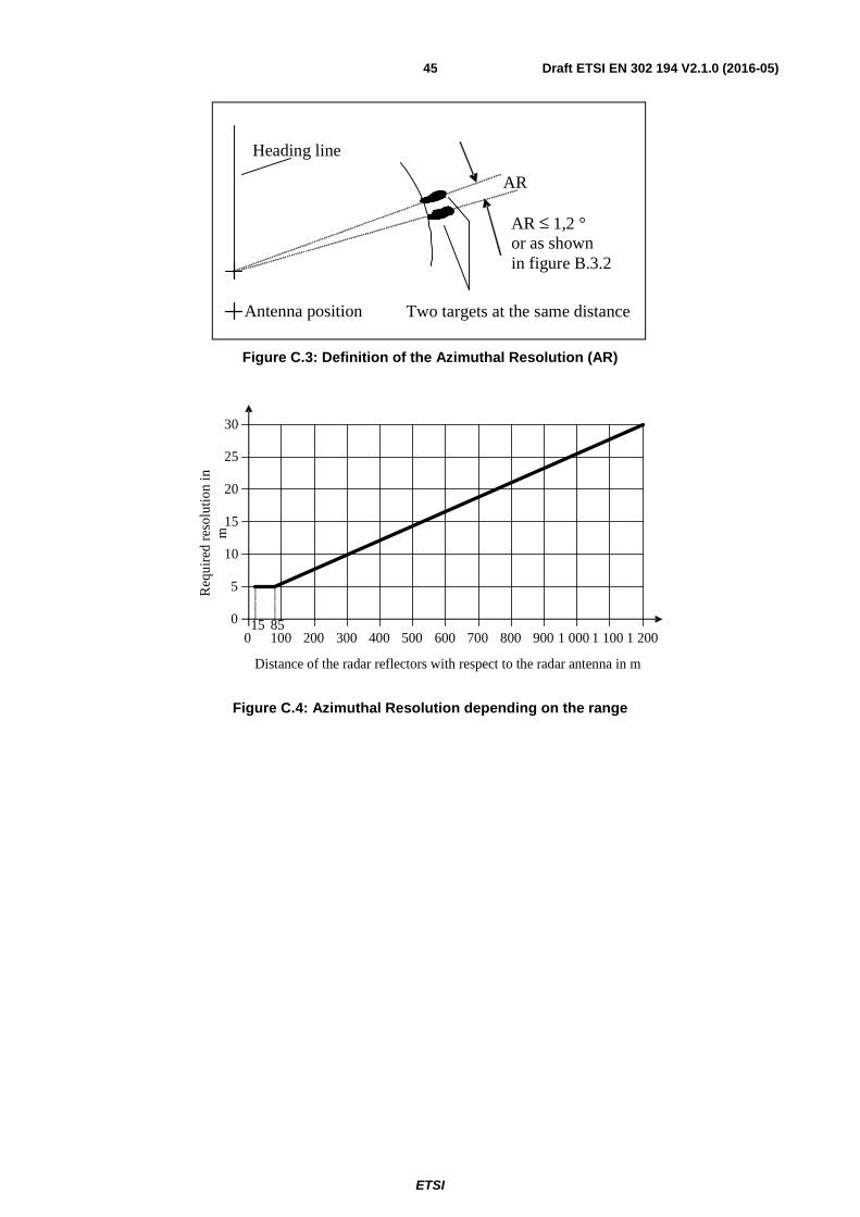
ETSI
Draft ETSI EN 302 194 V2.1.0 (2016-05) 45
AR ≤ 1,2 °or as shownin figure B.3.2
AR
Antenna position
Heading line
Two targets at the same distance
Figure C.3: Definition of the Azimuthal Resolution (AR)
30
25
15
10
5
0
20
200 300 400 500 600 700 800 900 1 000 1 100 1 2008515
0
Distance of the radar reflectors with respect to the radar antenna in m
100
Req
uire
d re
solu
tion
inm
Figure C.4: Azimuthal Resolution depending on the range

ETSI
Draft ETSI EN 302 194 V2.1.0 (2016-05) 46
Annex D (normative): Transmission power and unwanted emissions of radar systems; measuring methods
D.1 Measurements with dismounted antenna Measurements with dismounted antenna shall take place as shown in figure D.1.
1.
2.
3.
4.
5. 6
.
1. Radar transceiver
2. Adapter: Rotary Joint –Wave Guide (WG)
3. High power directional coupler (–40 dB)
4. Dummy load
5. Adapter WG-coax or MW-detector
Figure D.1: Measurement of the operation frequency and the pulse power
D.2 Free field measurements Free field measurements shall take place as shown in figure D.2.
≅ 200 m
≥ 10 m
12.
3.
1. Radar equipment under test
2. Directional antenna
3. Notch filter
4.
5.
Figure D.2: Measurement of spurious emissions and out of band emissions, placement of components
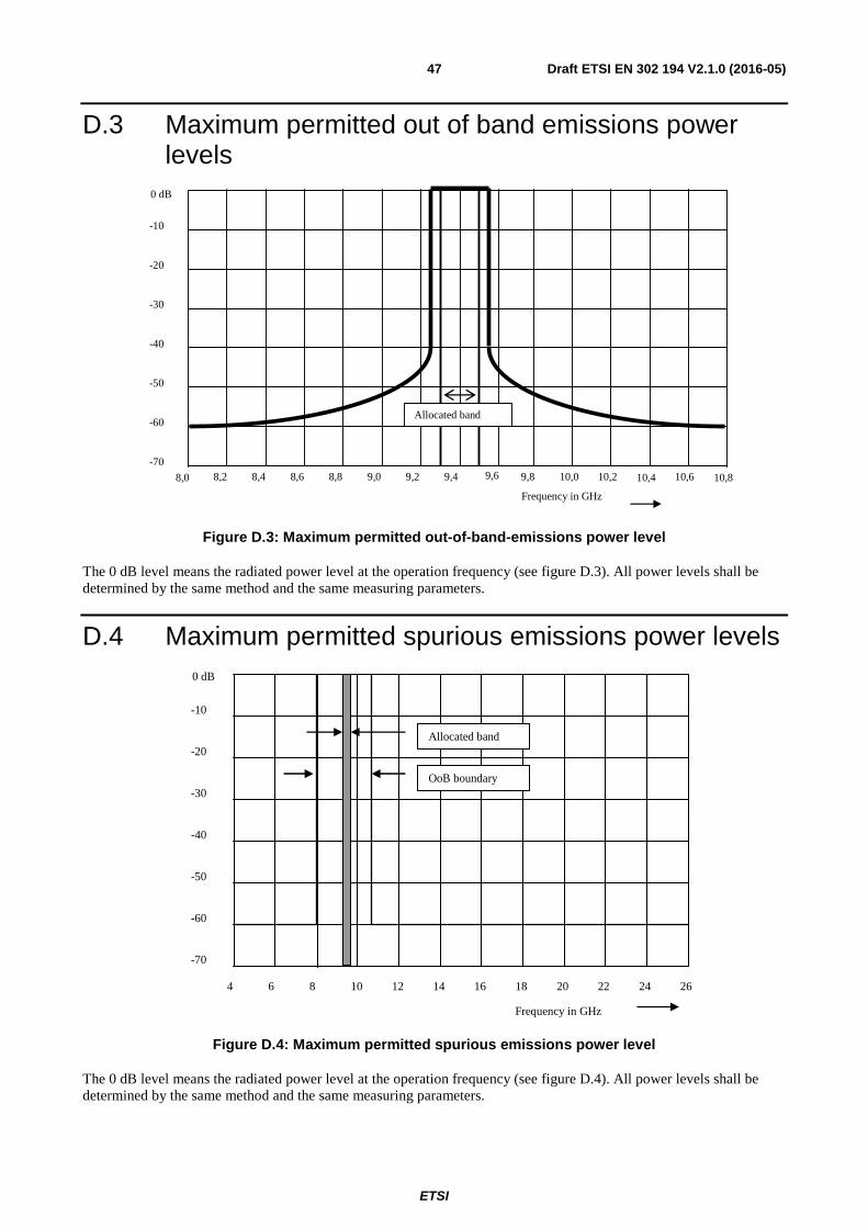
ETSI
Draft ETSI EN 302 194 V2.1.0 (2016-05) 47
D.3 Maximum permitted out of band emissions power levels
0 dB
-10
-20
-30
-40
-50
-60
-70 8,2 8,4 8,6 8,8 9,0 9,2 9,4 9,6 9,8 10,0 10,2 10,4 10,6
Frequency in GHz
8,0 10,8
Allocated band
Figure D.3: Maximum permitted out-of-band-emissions power level
The 0 dB level means the radiated power level at the operation frequency (see figure D.3). All power levels shall be determined by the same method and the same measuring parameters.
D.4 Maximum permitted spurious emissions power levels
4 6 8 10 12 14 16 18 20 22 24 26
0 dB
-10
-20
-30
-40
-50
-60
-70
Frequency in GHz
Allocated band
OoB boundary
Figure D.4: Maximum permitted spurious emissions power level
The 0 dB level means the radiated power level at the operation frequency (see figure D.4). All power levels shall be determined by the same method and the same measuring parameters.

ETSI
Draft ETSI EN 302 194 V2.1.0 (2016-05) 48
Annex E (normative): Type approval procedure
E.1 Type Testing Radar equipment for the navigation on inland waterways within the Rhine and Danube may only be installed aboard ships if it has been established by means of a type test that the equipment meets the specified minimum requirements laid down in the present document.
E.2 Application for type testing Applications for the type testing of radar equipment shall be made to a competent authority in one of the member countries of the CCNR and DC. The competent testing Authorities are to make known to the CCNR and to the DC.
Each application shall be accompanied by the following documents:
a) Two copies of a detailed technical manual.
b) Two complete sets of circuit diagrams and service manuals.
c) Two copies of a detailed operator's manual.
d) Two copies of a summarized operator's manual.
By means of tests, the applicant shall establish or cause to be established that the radar equipment meets the minimum requirements of the present document.
The results of the test and the measurement reports of the horizontal and vertical radiation pattern of the antenna shall be attached to the application.
These documents and the information obtained during type testing shall be retained by the Administration.
For type-testing purposes, an applicant is understood to be any legal or natural person whose name, trademark or any other form of identification is used to market the equipment submitted for type testing.
E.3 Type-approval If the equipment meets the specified minimum requirements, the testing authority shall issue a certificate of conformity. If the equipment fails to meet the minimum requirements, the applicant shall be notified in writing of the reasons for its rejection. After a certificate of conformity has been issued by the testing authority the type-approval certificate may be granted by the Administration. The Administration shall inform the CCNR of the equipment it has type-approved.
On initiative of the Administration, the testing authority is entitled to take an equipment from the production series at any time whatsoever for the purpose of verification. If this verification reveals shortcomings in the equipment, type-approval may be withdrawn. The type-approval shall be withdrawn by the Administration that issued it. The type-approval shall be valid for a period of ten years and may be renewed on request.
E.4 Identification, approval number of the equipment Each unit of the equipment shall be provided in an indelible fashion with the name of the manufacturer, the trade designation of the equipment, the type of unit and a serial number. The number under which type-approval was granted shall be provided indelibly on the display unit in such a way that it remains clearly visible after the equipment has been installed.

ETSI
Draft ETSI EN 302 194 V2.1.0 (2016-05) 49
E.5 Composition of a type-approval number: The approval is combined with an approval number of the following syntax:
R-N-NNN R = a one digit character of the River
Whereby: R = Rhine
D = Danube
N = a one-digit number of the national Administration
Whereby: 1 = F⇒ France
2 = N⇒ Netherlands
4 = D⇒ Germany
6 = B ⇒ Belgium
7 = CH⇒ Switzerland
NNN = a three digit number, to be determined by the Administration.
The type-approval number shall only be used in combination with the associated approval. It shall be the responsibility of the applicant to produce and affix the type-approval number.
The Administration informs immediately the CCNR and / or the DC of the issued approval number.
E.6 Manufacturers statement Each equipment shall be accompanied by a manufacturer's statement to the effect that the equipment meets the prevailing minimum requirements and that its construction is identical, without restriction, to that of the equipment submitted for type testing.
E.7 Modifications of approved equipment Any modification made to equipment already approved shall render the type-approval invalid. Whenever modifications are planned, details shall be sent in writing to the Administration.
The Administration will decide whether the approval still applies or whether an additional or new type-test is necessary. If a new approval is granted, a new approval number shall be issued.
E.8 Instruction manual A detailed operator's manual shall be supplied with each equipment. It shall be available in the users' language and shall contain at least the following information:
a) Activation and operation.
b) Maintenance and servicing.
c) General safety instructions (health hazards, e.g. the influencing of pacemakers and similar by electromagnetic irradiation).
d) Instructions as to the correct technical installation.
A summarized operator's manual in durable fashion shall be supplied with each equipment. It shall be available in the users' language.

ETSI
Draft ETSI EN 302 194 V2.1.0 (2016-05) 50
E.9 Installation and operational tests For the sake of installation, replacement and performance test, the directives of the Central Commission for the Navigation on the Rhine apply.
The radar installation, including the antenna, shall be in such manner that the maintenance of the radar system is not including substantially impaired. Guidance on installation shall be given in the manufacturer's documentation.

ETSI
Draft ETSI EN 302 194 V2.1.0 (2016-05) 51
Annex F (informative): Calculation of the equivalent radar cross section RCS
F.1 Definition The only body with omni-directional reflection characteristics is a sphere. To define the reflection capability of any object, the cross section of a sphere with the same reflection capability as the compared object delivers the RCS of the object.
The equivalent radar cross section RCS (Formula sign: σ, unit: m2) of a radar reflector (corner reflector) with triangular areas for a frequency of 9 400 MHz (λ ≅ 3,2 cm) is calculated according to the formula (F.1):
2
4
032,03
4
×××= aπσ (F.1)
a = edge length in metres (m) as shown in figure F.1.
A standard reflector as defined in the present document has a radar cross section of σ = 10 m2. To have this RCS the short edges of the triangular areas of a corner reflector has an edge length of a = 0,222 m.
a
Figure F.1: Edge a of a corner reflector

ETSI
Draft ETSI EN 302 194 V2.1.0 (2016-05) 52
Annex G (informative): Bibliography
• CCNR (Central Commission for the Navigation of the Rhine): www.ccr-zkr.org
• ZKR 1989-II-33 (1990): "Regulations regarding the minimum requirements and test conditions for radar equipment used for inland waterways navigation. (Vorschriften betreffend die Mindestanforderungen und Prüfbedingungen für Navigationsradaranlagen für die Binnenschifffahrt)".
• ZKR 1989-II-35 (1990): "Regulations regarding the installation and function test for radar equipment and rate of turn indicators used for inland waterways navigation. (Vorschriften betreffend den Einbau und die Funktionsprüfung von Navigationsradaranalgen und Wendegeschwindigkeitsanzeiger für die Binnenschifffahrt)".
• ZKR 2001-I-16 (2001): "Inland ECDIS Standard".

ETSI
Draft ETSI EN 302 194 V2.1.0 (2016-05) 53
History
Document history
V1.1.2 October 2006 Publication as ETSI EN 302 194-1
V1.1.2 August 2008 Publication as ETSI EN 302 194-2
V2.1.0 May 2016 EN Approval Procedure AP 20160308: 2016-05-05 to 2016-08-03