encribd com mech 4 sem course info feb june 07
TRANSCRIPT

7/21/2019 Encribd Com Mech 4 Sem Course Info Feb June 07
http://slidepdf.com/reader/full/encribd-com-mech-4-sem-course-info-feb-june-07 1/66
PESIT
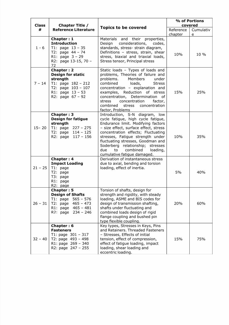
DESIGN OF MACHINE ELEMENTS - I
Subject Code: AU46Faculty: RSS No. of Hours: 52
7/21/2019 Encribd Com Mech 4 Sem Course Info Feb June 07
http://slidepdf.com/reader/full/encribd-com-mech-4-sem-course-info-feb-june-07 2/66
% of PortionscoveredClass
#Chapter Title /
Reference LiteratureTopics to be covered
Referencechapter
Cumulative
1 - 6
Chapter : 1Introduction
T1: page 13 – 35
T2: page 44 – 74R1: page 3 – 29R2: page 13-15, 70 –72
Materials and their properties,Design considerations, codes,standards, stress- strain diagram,
Definitions – stress, strain, shearstress, biaxial and triaxial loads,Stress tensor, Principal stress
10% 10 %
7 – 14
Chapter : 2Design for staticstrengthT1: page 182 – 212T2: page 103 – 107R1: page 13 – 53R2: page 67 – 92
Static loads – Types of loads andproblems, Theories of failure andproblems. Members undercombined loads, Stressconcentration – explanation andexamples, Reduction of stressconcentration, Determination ofstress concentration factor,combined stress concentrationfactor, Problems
15% 25%
15– 20
Chapter : 3Design for fatigue
strength T1: page 227 – 275T2: page 114 – 125R2: page 117 – 156
Introduction, S-N diagram, lowcycle fatigue, high cycle fatigue,Endurance limit. Modifying factors– size effect, surface effect, stressconcentration effects; Fluctuatingstresses, Fatigue strength underfluctuating stresses, Goodman andSoderberg relationship; stressesdue to combined loading,cumulative fatigue damaged.
10% 35%
21 – 25
Chapter : 4
Impact Loading T1: pageT2: pageT3: pageR1: pageR2: page
Derivation of instantaneous stress
due to axial, bending and torsionloading, effect of inertia.
5% 40%
26 – 31
Chapter : 5Design of Shafts
T1: page 565 – 576T2: page 465 – 473R1: page 465 – 481R2: page 234 – 246
Torsion of shafts, design forstrength and rigidity, with steadyloading, ASME and BIS codes fordesign of transmission shafting,shafts under fluctuating andcombined loads design of rigid
flange coupling and bushed pintype flexible coupling.
20% 60%
32 – 40
Chapter : 6FastenersT1: page 301 – 317T2: page 493 – 498R1: page 269 – 340R2: page 247 – 255
Key types, Stresses in Keys, Pinsand Retainers. Threaded Fasteners– Stresses, Effects of initialtension, effect of compression,effect of fatigue loading, impactloading, shear loading andeccentric loading.
15% 75%

7/21/2019 Encribd Com Mech 4 Sem Course Info Feb June 07
http://slidepdf.com/reader/full/encribd-com-mech-4-sem-course-info-feb-june-07 3/66
Text Books:T1: Mechanical Engg. Design by Joseph. E Shigley & Charles R MirchKe. Tata 6th Ed
2003. Mc Graw Hill Edition 2001T2: Design of Machine Elements by C.S.Sharma and Kamlesh Purohit, PHI 2003.
Reference Books:
R1: Machine Design by Maleev & Hartman, CBS Publishers & Distribution, New DelhiR2: Design of Machine Elements – V.B.Bhandari,. Tata McGraw Hill Pub. New DelhiR3: Theory and Problems of Machine Design by Hall Holowenko, (Schaum series)R4: Machine Design by Robert L Norton, Pearson Education Asia, 2001R5: Design of Machine Elements by M.F.Spotts, PHI 2003.R6: Machine Design by Paul H- Black, D.E.Adams McGraw Hill, 2001
Design Data Hand Books:Design Data Hand Book – K.Lingaiah, McGraw Hill, 2nd Ed, 2003
1. Design Data Hand Book – K.Mahadevan & Balaveera Reddy, CBS Publication2. Machine Design Data Hand Book by H.G.Patil, Shri Shashi Prakashan, Belgaum
41 – 48
Chapter : 7Power Screws T1: page 291 – 300T2: page 266 – 273R1: page 441 – 450R2: page 163 – 185
Mechanics of power screw,stresses in power screws,Efficiency and self locking.
15% 90%
49 – 52
Chapter : 8
Mechanical joints: T1: page 336 – 352T2: page 171 – 227R1: page 213 – 256R2: page 213 – 229
Cotter and knuckle joints, RivetedJoints – Types, rivet materials,Failures of Riveted joints,Efficiency, Boiler Joints, Tank andStructural Joints, riveted brackets.Welded joints – Types, strength ofbutt and fillet welds, Eccentricallyloaded welds.
10% 100%

7/21/2019 Encribd Com Mech 4 Sem Course Info Feb June 07
http://slidepdf.com/reader/full/encribd-com-mech-4-sem-course-info-feb-june-07 4/66

7/21/2019 Encribd Com Mech 4 Sem Course Info Feb June 07
http://slidepdf.com/reader/full/encribd-com-mech-4-sem-course-info-feb-june-07 5/66
12. *A machine part is statically loaded and has yield strength of 350 MPa. For thefollowing stresses calculate the factor of safety using the following theories of failure:
(i) Maximum normal stress theory.(ii) Maximum shear stress theory(iii) Von mires theory(a) σ1 = -70MPa, σ2 = 0MPa(b) σ1 = 70MPa, σ2 = -70MPa(c) σ1 = 70MPa, σ2 = 70MPa
13. A tension member shown in figure 7, supports an axial load P. It is necessary toreplace this member by one having a 15 mm hole as shown. Determine the thicknesst and radius r at the fillet of the second member, so that the maximum stress will notexceed that of the first member.(10)
14. Find the value of the max. Stress on the fillet if the stress concentration factor for thefilleted flat bar in tension is 1.8 and D/d is 1.2 as shown in figure 8. Determine thefactor of safety if it is made of steel having yield strength of 320N/mm2.(10)
15. A rod of circular cross section is to sustain a torsional moment of 300 KNm and abending moment of 200 KNm. Selecting a suitable material and assuming anappropriate value for the factor of safety, determine the diameter of the rod as per
the following theories of failure:(i) Maximum shear stress theory for failure.(ii) Von Mises or distortion energy theory for failure.(iii) Total energy theory for failure.
(15)16. Figure 9 shows a crank shaft loaded by a force Fy = 1500N
(i) Draw separate free body forces, bending moments and turning moments thatact on the crank and on the shaft. Label the directions of the co ordinates axison these diagrams.
(ii) Compute the maximum torsional stress and the maximum principal stress in thecrank at a section 80mm from the pin-end.
(iii) Locate the stress element on the top surface of the shaft at A and find the
principal stresses and the maximum shear stress at the same point.(15)
17. Obtain the magnitude of normal and shear stresses at the extreme fibers on thecross section AA of a clamp loaded as shown in figure 11(12)
18. Determine the diameters of a round rod to sustain a combined torsional load of 1500Nm and a bending moment of 100 Nm by the following theories of failure. Materialselected for the rod has a value of 300 MPa and 180 MPa for the normal stress andshear stress at yield respectively. Take a value of 2.50 for the factor of safety.
(i) Maximum shear stress theory(ii) Octa hedral shearing stress theory
(12)
19. Explain six theories of failure.(8)
20. Determine normal stresses at the extreme fibers on the cross section AA of a C-clamp loaded as shown in figure 12.(12)
21. Explain the following theories of failure(i) Maximum principle stress theory for failure(ii) Maximum shear stress theory for failure(iii) Octahedral shear stress theory for failure
(9)22. A round rod of diameter 30.0 mm is to sustain an axial compressive load of 20 kN
and a twisting moment of 150 Nm. The rod is made of carbon steel C40. Determine
factors of safety as per following theories of failure

7/21/2019 Encribd Com Mech 4 Sem Course Info Feb June 07
http://slidepdf.com/reader/full/encribd-com-mech-4-sem-course-info-feb-june-07 6/66
(i) Maximum principal strain theory for failure(ii) Maximum Elastic energy theory for failure(iii) Distortion energy theory for failure
(12)23. * A rectangular plate 15mm thick made of brittle material is shown in fig below.Calculate the stresses at each of three holes.(8)
3 Ø 5 Ø 10 Ø

7/21/2019 Encribd Com Mech 4 Sem Course Info Feb June 07
http://slidepdf.com/reader/full/encribd-com-mech-4-sem-course-info-feb-june-07 7/66
Ch a p t e r – 3 D e s i g n f o r f a t i g u e s t r e n g t h
1. A shaft can transmit power of 20 KW at 1000 RPM. The actual torque transmitted byshaft is ± 60% of the mean torque calculated. Shaft is also subjected to a variablebending moment of 500 N-m to 1000 N-m. The maximum bending moment occurs atthe same instant as that of maximum torque. Determine the diameter of the shaftrequired selecting suitable material. Take factor of safety 2, size factor = 0.85, andsurface factor = 0.8. (14)
2. A stepped shaft shown in figure 13 is subjected to the transverse load. The shaft ismade of steel with ultimate tensile strength of 400 MPa. The shaft is machined.Determine diameter of shaft based on the factor of safety of 2.(14)
3. Determine maximum stress induced in the following cases taking stressconcentration in case
(i) A rectangular plate under an axial load of 10KN. (figure 14)(3)
(ii) The circular shaft with a step under transverse load of 10KN asshown (figure 15)
(3)(iii) The shaft under a twisting moment of 50Nm. (figure16)
(3)4. Explain the significance of Goodman’s line and soderberg line in design of members
subjected to reversal of stresses.(8)
5. A steel member of circular cross section is subjected to a torsional stress that variesfrom 0 to 35 MPa and at the same time it is subjected to an axial stress that variesfrom 14 MPa to 28 MPa. Neglecting stress concentration and column effect determine
(i) the maximum equivalent shear stress.(ii) the design factor of safety based upon yield in shear. The material has an
endurance limit = 260 MPa and a yield strength = 480 MPa.
The size factor may be taken as UNITY and the surface has a mirror polish.(12)
6. A stepped shaft with its diameter reduced from ‘1.2 d’ to ‘d’ has a fillet radius of0.1d. Determine the diameters of the shaft and the radius of fillet to transmit apower of 60 KW at a rated of 1000 RPM limiting the maximum shear stress inducedto 65MPa. (7)
7. A shaft of circular cross section is subjected to a turning moment that fluctuatesbetween 800 KNm and 600 KNm and also a bending moment that fluctuates between+ 500 KNm and – 300KNm. The material selected for the shaft has a shear stressvalue of 100 MPa at endurance limit and a shear stress value of 120 MPa of the yieldlimit. Determine the diameter of the solid circular shaft taking a value of 2.50 for thefactor of safety. Surface factor, size factor and load factor can be taken as 0.90, 0.85and 1.0 respectively. Shear stress concentration factor is 1.80 and the notch
sensitivity is 0.95.
8. A cantilever beam of rectangular cross section has a span of 800 mm. Therectangular cross section of the beam has a depth of 200 mm. The free end of thebeam is subjected to a transverse load that fluctuates between 8 KN down to 5KNup. Selecting carbon steel C 30 as material for the beam and selecting a value of2.50 for the factor of safety, determine the width of rectangular cross section.Surface factor and size factor are respectively 0.95 and 0.90. Stress concentrationfactor is given to be 1.65 (14)
9. A round rod of diameter 1.2d is reduced to a diameter d with a fillet radius of 0.1d.This stepped rod is to sustain a twisting moment that fluctuates between +2.5KNm
and +1.5KNm together with a bending moment that fluctuates between +1KNm

7/21/2019 Encribd Com Mech 4 Sem Course Info Feb June 07
http://slidepdf.com/reader/full/encribd-com-mech-4-sem-course-info-feb-june-07 8/66
and –1.0KNm. The rod is made of carbon steel C40. Determine a suitable value ford. (14)
10.*A cantilever beam of circular cross-section is subjected to an alternating stress at apoint on the outer fiber in the plane of the support that varies from 21 MPa(compression) to 28 MPa (tension). At the same time there is an alternative stressdue to axial loading that varies from 14 MPa (compression) to 28 MPa (tension).The material has an ultimate strength of 412 MPa, yield strength of 309 MPa.Assume that actual stress concentration factor =1, size correction factor = 0.85,and surface correction factor = 0.9. Determine
i) the equivalent normal stress due to axial loadingii) the equivalent normal stress due to bending andiii) the total equivalent normal stress due to axial loading and bending
(12)
Chapter – 4 Impact Loading
1. Explain the influence of stress raiser on impact strength(06)
2. A 5 Kg block is dropped from a height of 200 mm on to a beam shown in figure 4. The material has an allowable yield stress of 50 MPa. Determine the dimensions ofthe rectangular section, whose depth is 1.5 times of the width. Take E= 70MPa.(14)
3. A weight of 1400 N is dropped on to a collar at the lower end of a vertical steel shaftof 3m long and 25 mm. diameter, calculate the height of drop if the maximuminstantaneous stress produced is not to exceed 120 MPa. Take E = 2.1 x 10⁵ MPa.(5)
4. Derive an expression for shock/impact factor.(5)
5. A cantilever beam of span 800.0 mm has a rectangular cross section of depth200.0m. The free end of the beam is subjected to a transverse load of 1KN, dropped
onto it from a height of 40.0 mm. selecting a suitable material and assuming anappropriate value for the factor of safety, determine the width of the rectangularcross section. (8)
6. Find the maximum stress due to impact in the bolt and in the beam shown in figure10. Assume the same material, namely steel, for both the members.
Chapter – 5 Design of Shafts
1. A horizontal piece of commercial shafting is supported by two bearing 1.5 m apart. Akeyed gear 20o involute and 200 mm in diameter is located 400 mm to the left ofright bearing and is driven by a gear directly behind it. A 600 mm diameter pulley iskeyed to the shaft 600mm to the right of left bearing and drives a pulley with a
horizontal belt directly behind it. The tension ratio of the belt is 3:1, with the slackside on top. The driver transmits 50KW at 350 RPM, Kb= Kt = 1.5.
a) Draw the moment diagramb) Calculate the diameter of the solid shaft requiredc) Calculate the torsional deflection in degrees
(20)2. Design a bush type flexible coupling to connect motor and centrifugal pump shafts.
Motor transmits 10 KW at 1440 RPM. Allowable stress in shear for shaft, key andbolts are 40 MPa. Allowable bearing pressure for rubber bush is 0.3 MPa. Check forstresses. (12)
3. Three identical pulleys of 500 mm diameter and weighing 500 N each are mounted
on a line shaft supported on two bearings 4000 mm apart. The pulley A is mountedat 300 mm to the right of left bearing and receives 30KW at 200RPM from a pulleyvertically below it. The pulley B is mounted 1000 mm to the right of left bearing and

7/21/2019 Encribd Com Mech 4 Sem Course Info Feb June 07
http://slidepdf.com/reader/full/encribd-com-mech-4-sem-course-info-feb-june-07 9/66
delivers 6KW to a pulley through a belt drive inclined backward at 45o to the vertical.The remaining power is taken out through another pulley C which is mounted at 3000mm to the right of left bearing and drives a planning machine the drive being 30o tothe front of the vertical. The angle of lap for all pulleys may be taken as 180o and thecoefficient of friction is 0.3. The working stress in shear for the shaft material is80N/mm2. Determine the diameter of the shaft.(20)
4. Design a bushed pin type flexible coupling to transmit 90 KW at 1440 RPM forconnecting two shafts of diameter 60 mm. Assume bearing pressure on the bushesas 0.35N/mm2, allowable shear stress in the material of the pins as 45 N/mm2 andallowable bending stress in the material of the pin is 80 N/mm2.
(14)5. Write a brief note on materials and heat treatments used for the shaft.
(06)6. A 1.2 m hollow shaft is subjected to bending moment 900N-m and turning moment
600 N-m. The shaft is also subjected to an end thrust 1.2KN. Taking d i /do = 0.7 andmaterial of the shaft to be cold rolled steel, determine the inner and outer diametersof the shaft. Consider heavy shock condition.
7. A 250mm diameter solid shaft is used to drive the propeller of a marine vessel. It isnecessary to reduce the weight of the shaft by 70%, what would be the dimensions
of a hollow shaft made of the same material as the solid shaft.(5)
8. A shaft is mounted between bearings located 9.5 m apart the transmits 10000 KW at90 rev/min. The shaft weighs 66000N has an outside diameter of 450 mm and insidediameter of 300 mm. Determine the stress induced in shaft and the angulardeflection between bearing. Do not neglect the weight of the shaft.
(10)9. Design a cast Iron flange coupling (protected type) to connect two shafts and
transmits a torque a 5000 Nm. The following permissible stresses may be used.Permissible shear stress for shaft, bolt and key material = 50 MPa. Permissible shearstress for CI = 16MPa.
10. Compare the weight, strength and stiffness of a hollow shaft of the same external
diameter as that of solid shaft. The inside dia. of the hollow shaft being half theexternal diameter. Both the shafts have the same material and length.(10)
11. A line shaft is to transmit 600 KW at 500RPM. The allowable shear stress for thematerial of the shaft is 42N/mm2 (42MPa). If the shaft carries a central load of 900Nand is simply supported between bearing 3 meter apart, determine the diameter ofthe shaft. The maximum tensile or compressive stress in not exceed 50 MPa.
(10)12. A shaft is required to transmit 1 MW power at 240RPM. The shaft must not twist
more that 1o on a length of 15 diameters. If the modulus of rigidity for the materialof the shaft is 80 KN/mm2, find the diameter of the shaft and the shear stressinduced.
13. Design a cast iron protective flange coupling to connect two shafts in order totransmit 7.5 KW at 720 RPM. the following permissible stresses may be usedpermissible shear stress for shaft, bolt and key material = 33MPa. Crushing stress forbolt and key material = 60 MPa. Shear stress for cast iron = 15MPa.
14. The shaft of uniform diameter as shown in figure 17 carries belt pulleys at A and Bwith vertical belts. It is supported in bearings at C and D. the shaft transmits 10 KWat 400 rpm. The tension on the tight side of belt A is 2000 N, and that on the slackside of belt B is 900N. Pulley A weighs 200 N and pulley B 400 N. Estimate suitablediameter for the shaft, adopting a working shear stress of 45 MPa.
15.
State the advantages of hollow shafts over solid shafts in transmission of power(5)

7/21/2019 Encribd Com Mech 4 Sem Course Info Feb June 07
http://slidepdf.com/reader/full/encribd-com-mech-4-sem-course-info-feb-june-07 10/66
16. A 60 cm pulley A receives 15 KW at 500 RPM from below at angle of 45o as shown inthe figure 18. A gear C with 450 mm pitch circle diameter delivers 30% of the powerhorizontally to the right gear D with pitch circle diameter of 300 mm delivers theremaining power downward to the left at an angle of 30o below the horizontal. Boththe gears have 20o involute teeth. Assuming working stress in shear 40 MN/m2 and intension at 80 MN/m2 and in tension as 80 MN/m2 for the shaft material. Design theshaft of uniform diameter. The ratio of tensions in the belt is 2.(20)
17. Design a protected type CI flange coupling for a steel shaft transmitting 15 KW at1200 RPM. take the maximum torque to be 20% more than the full-load torque.Draw to scale the coupling designed giving all important dimensions.(20)
18. A power transmission shaft is supported on two bearings 2000.0 mm apart. Theshaft receives a power of 40KW through a belt drive situated, at a distance of 600.0mm to the right of the left bearing. The weight & diameter of the pulley arerespectively 800N and 400.0mm. The belt moves towards the observer below thehorizontal, inclined at 60o to it. The ratio of the belt tensions is 3.0. The power istransmitted out of the shaft through a gear drive located on the shaft at a distance of500.0 mm to the left of the right bearing. The weight and pitch diameter of the gearmounted on the shaft are respectively 600N and 300.0 mm. The gear which receives
from this gear is located exactly behind. The teeth are of involute profile with apressure angle of 20o. Determine the diameter of the solid circular shaft selectingcarbon steel C40 as material & assuming a value of 2.50 for the factor of safety.(20)
19. Design a protected type of CI flange coupling to connect two shafts of the samediameters and transmit 150 KW at 100 RPM. Select suitable materials and factors ofsafety. Assume 25% over load.(14)
20. A power transmission shaft 1200.0 mm long receives power of 25 KW through a beltdrive located at its right extreme end. The shaft is supported at two points A and B.While A is at the left extreme end, B is at a distance of 300mm from the right
extreme end. The pulley on the shaft has a diameter of 500mm and weighs 800N.The belt on the pulley moves below towards the observer making an angle of 30o with the vertical. The power is taken out through a gear drive located at distance of400mm form the left support. The gear mounted on the shaft has a pitch diameter of250mm and weighs 500 N. The other gear which receives power form this gear isplaced just above this gear. The pressure angle is 20o. The shaft operates at 750RPM. Selecting a suitable material and assuming an appropriate value for the factorof safety, determine the diameter of the solid circular shaft.
21. A power transmission shaft 1800 mm long is supported at two points A and B.Whereas A is at a distance of 300mm from the left extreme end of the shaft, B is atthe right extreme end. A power of 50 kW is received at 500 RPM through a gear drivelocated at the left extreme end of the shaft. The gear mounted on the shaft here has
a pitch diameter of 300mm and weighs 700N. The driver gear is located exactlybehind. A power of 30KW is given out through a belt drive located at a distance of600mm from the left support. The pulley mounted on the shaft has a diameter of 400mm and weighs 1000N. The belt is directed towards the observer below thehorizontal and inclined at 45o to it. The ratio of belt tensions is 3. the remainingpower is given out through a gear drive located at a distance of 400 mm from theright support. The driver gear has a pitch diameter of 200 mm and weighs 500N. Thedriven gear is located exactly above. Selecting appropriate material and assuming asuitable value for the factor of safety determine the diameter of a solid shaft for thepurpose.
22. Design a rigid flanged coupling to transmit a power of 40 kW at a rated speed of100RPM
(10)

7/21/2019 Encribd Com Mech 4 Sem Course Info Feb June 07
http://slidepdf.com/reader/full/encribd-com-mech-4-sem-course-info-feb-june-07 11/66
Cha p t e r – 6 F a st e n e r s
1. Determine load capacity of the riveted joint loaded as shown in figure 19, if the shearstress of the material of the rivet is 100 N/ mm2.(12)
2. A 100mm shaft rotating at 100 RPM transmit 300 hp power is taken off through agear whose hub is 200 mm long. The key is made of steel having an ultimateshearing stress of 350N/ mm2. Using a factor of safety of 5, determine the width ofkey required. (6)
3. A bolt in a steel structure is subjected to a tensile load of 9 KN. The initial tighteningload on the bolt is 5 KN. Determine the size of the bolt taking allowable stress for thebolt material to be 80 MPa.
(08)4. A flanged bearing is fastened to a frame by means of four bolts spaced equally on
400mm bolt circle as shown in figure 20. The diameter of the flange is 500 mm and aload of 200 KN acts at a distance of 250 mm from the frame. If the tensile stress inthe bolt is not to exceed 63 MPa. Determine the bolt size.
(12)5. Select a rectangular parallel key for transmitting a power of 50 KW at a rated speed
of 500 RPM to mount a hub of length 60mm on a solid circular shaft ofdiameter 50 mm. (6)
6. Figure 21 shows the cylindrical head of a pressure vessel using 10 bolts and aconfined gasket. The static pressure in the cylinder is 6N/mm2. Select the size of themetric bolts for a factor of safety of 3.
7. For the system shown in figure 22 find the maximum stress in the weld. Find the sizeof the bolt.(20)
8. Determine the power capacity ratio of the two system: one a 24 mm diameter shaftwith a 48 x 6 x 6 mm key and another a 24 mm diameter shaft with a 6 mm dia pin.The stress concentration for the key way in the shaft is 1.3, and that for the pinnedshaft is 1.75. Assume only torsional load and the same material for all parts.
(12)

7/21/2019 Encribd Com Mech 4 Sem Course Info Feb June 07
http://slidepdf.com/reader/full/encribd-com-mech-4-sem-course-info-feb-june-07 12/66
Chapter – 7 Power screws
1. A split nut used with a lead screw is propelled at a speed of 5 m/min, against a loadof 20KN, along the spindle of a square thread (single start), having nominal diameterof 30 mm and a pitch of 6 mm. The axial thrust is absorbed by a collar of 100mmoutside diameter and 70 mm inside diameter. Assuming suitable coefficient offriction, determine :
(i) Power required to drive(ii) height of the bronze nut required
if allowable bearing pressure is 17MPa.(10)2. The following data applies to a C clamp shown in Figure 23. The screw has
trapezoidal metric thread.Pitch – 1.75mm, Outer dia. of screw – 12mm, Root Dia. – 9.853Coefficient of thread friction – 0.12
Coefficient of collar friction – 0.25Friction circle radius of collar – 6mmMaximum thrust on the screw – 4 KN
Determine:(i) Length of handling if the operator exerts a force of 80N at the end of the handle(ii) Maximum shear stress induced in the body of the screw and where does it exist.
(iii) Bearing pressure on threads.(14)3. A machine weighing 20KN is to be raised by a single start square threaded 50mm
diameter, 8mm pitch screw jack at a maximum speed of 600m/min. If the coefficientof friction between the threads is 0.2, determine the power required to lift themachine. The thrust collar of the screw has inside diameter of 30mm and out sidediameter of 60mm. The coefficient of collar friction is 0.1. (10)
4. A 15KN screw jack with a maximum extension of 150 mm has double square threads.Using an allowable compressive stress of 80N/mm2 and bearing pressure on thethreads 17.5 MPa Find:
(ii) Size of screw(iii) Height of nut
(10)5. A shaft straightner is designed to exert a load of 25 KN. It utilizes a square threaded
screw having outside diameter of 75mm and pitch of 6 mm determine the forcerequired to operate the handwheel of 300 mm diameter if the coefficient of frictionfor threads is 0.12. Also determine efficiency of straightner.
(8)6. What are power screws? State their applications.
(4)
7. Design the following parts of 20 KN screw jack selecting suitable materials andassuming appropriate values for the factors of safety, for a travel of 200mm
(iv) Screw rod
(v) Nut(vi) The hand lever
8. A turn buckle is used to tighten a wire rope. The threads are single right and lefthand square in section. The outside diameter of the screw is 38mm and the pitch is8.5 mm. The coefficient of friction between the screws and nuts is 0.15. what is themaximum shear stress induced in the screw of the turn buckle if the rope is to betightened to a tension of 8 KN.
9. Select thread proportions for the screw rod of a screw press to sustain an axialcompressive load of 40 KN for an unsupported length of 350.0mm. select anappropriate material and assume a suitable value for the factor of safety.(10)
10. A weight of 500KW is raised at a speed of 6m/min by two screw rods with squarethreads of 50 x 8 cut on them. The two screw rods are driven through bevel geardrives by a motor. Determine:

7/21/2019 Encribd Com Mech 4 Sem Course Info Feb June 07
http://slidepdf.com/reader/full/encribd-com-mech-4-sem-course-info-feb-june-07 13/66
(i) The torque required to raise the load(4)
(ii) The speed of rotation of the screw rod assuming the threads are of doublestart(2)
(iii) The maximum stresses induced on the cross section of the screw rod(4)
(iv) The efficiency of screw drive(3)
(v) The length of nuts for the purpose of supporting the load(vi) check for overhaul
(2)11.Design a turnbuckle to take an axial load of 100KN. The material of which the turn
buckle is to be made has a design normal stress of 165 N/mm2 and design shearstress of 100N/mm2.(08)
Cha p t e r – 8 Me c h a n i c a l J o i n t s
1. Design the longitudinal joint for a boiler for a steam pressure of 2 MPa. Diameter of
the boiler is 1 m. Select a double riveted butt joint with a required efficiency of 75%.Take the following allowable stresses. σt = 80 MPa, τ = 60MPa, σc = 120 MPa.(10)
2. An eccentrically loaded bracket welded to its support is loaded as shown in figure 24.Determine the size of the weld required. (10)
3. A steel bracket is welded to a structure and loaded as shown in figure 25. Calculatethe size of the weld, taking the permissible stress in the weld to be 84 N/mm2.(12)
4. Design a sleeve type of cotter joint to connect two tie rods subjected to an axial pullof 60KN. The allowable stress of C – 30 material used for rods and cotters areσt = 65 N/mm2, σc = 75 N/mm2 and τ = 35 N/mm2. Cast steel material used for thesleeve has the allowable stresses σt = 70 N/mm2 and τ = 45 N/mm2
5. Design the longitudinal and circumferential joints for a boiler whose diameter in 2meters and is subjected to a pressure of 1 MPa. The longitudinal joint is a tripleriveted butt joint with an efficiency of about 85% and the circumferential joint is adouble riveted lap joint with an efficiency of about 70%. The pitch in the outer rowsof the rivets is to be double that in the inner rows and the width of the cover plates isunequal. The allowable stresses are σt = 70MPa, τ shear stress = 50MPa crushingstress σc = 120MPa. Assume that the resistance of the rivets in double shear is 1.875times that of single shear. (20)
6. A bracket as shown in figure 26 carries a load of 40000N. Calculate the size of weld,if the allowable shear is not exceed 80MPa.
(10)
7. Two lengths of mild steel flat tie bars 200 mm x 10mm are to be connected by adouble riveted double cover butt joint using 24 mm diameter rivets. Design the joint,if the allowable working stresses are 112 MPa in tension, 84 MPa in shear and200MPa in crushing.
8. Sketch and explain the types of riveted joint failure.(8)
9. A knuckle joint is required for a rod which has to withstand a tensile load of 100 KN.Find the diameters of the rod and the pin. safe working stress both in tension andshear are 80 MPa and 60 MPa respectively. Suggest the suitable dimensions for theentire joint.
10. Design and draw a fully dimensioned neat sketch in two view of a double riveted butt joint with double cover plates for the longitudinal seam of a boiler 1.5m in diameter
when working pressure is 1 MPa. Use the following data:

7/21/2019 Encribd Com Mech 4 Sem Course Info Feb June 07
http://slidepdf.com/reader/full/encribd-com-mech-4-sem-course-info-feb-june-07 14/66
Allowable stress in tension for steel plate = 80MPaAllowable stress in shear for rivets = 60 MPaAllowable stress in crushing for rivets = 120 MPa.
(12)11. Find the difference in the diameters to be allowed for shrinkage when a compound
cylinder 200 mm external diameter, 100 mm internal diameter and 150 mm diameterat the junction of the two tubes has a radial pressure of 31 MPa at the junction. TakeE = 2.1 x 10⁵ MPa and Poisson’s ratio = 0.25.(10)
12. A triple-rivetted butt-joint with equal cover plates is used to connect two plates 16mm thick. Design the joint if the allowable crushing stress for rivet and plates is60 MN/m2. Find the joint efficiency. Allowable shear stress for rivets: 45 MN/m2.Draw to scale two views of the designed joint giving all dimensions.
(10)
13. A bracket supporting a load is welded to a stanchion by four fillet welds of 6mm sizeas shown in the figure 28. What is the maximum value of P if the normal stress onthe throat section is not to exceed 98 MN/m2?(10)
14. Design a triple riveted butt joint with unequal widths of cover plates to join twoplates of thickness 10mm. The extreme row of rivets, which are in single shear, havea pitch which is twice the pitch of rivets in the inner rows. The allowable stresses areas follows:
Tensile stress of the material of the plates = 80 MPaShear stress of the material of the rivets = 60 MPaCrushing stress of the material of the rivets = 120MPaSketch the joint. Also determine the various strengths & efficiencies of the joint.
(10)15. Design a knuckle joint to transmit an axial load of 120 KN. The allowable stress for
the material of the joint are as follows: σt = 120 MPa and τ = 80 MPa(10)
16. Design a cotter joint to sustain an axial load of 80 KN. Material selected for the jointhas the following mechanical properties.
Normal stress at yield = 300 MPaShear stress at yield = 150 MPaAllowable bearing pressure = 40 MPa
(12)17. Design a longitudinal butt joint with equal widths of cover plates for a pressure vessel
of diameter 1200.0 mm subjected to an internal pressure of 0.90 MPa. A jointefficiency of 75% can be assumed at this stage. For practical reasons the pitch ofrivets is to be restricted a value not less than 3 d and not more than 3.5 d where d isthe diameter of the rivets. Material selected for the main plate and rivets has thefollowing safe values:
Design normal stress for material of the main plate = 120 MPaDesign shear stress of the material of the rivet = 80 MPaDesign Crushing stress of the material of the rivet = 160 MPaSketch the joint and determine the various efficiencies.(14)
18. Design a socket and spigot type of cotter joint to sustain an axial load of 100kN. Thematerial selected for the joint has the following design stresses. σt = 120 MPa, σc =160 MPa and pb = 60 MPa (10)
19. Design a triple riveted butt joint to join two plates of thickness 10 mm. The pitch ofrivets in the extreme rows, which are in single shear, is twice the pitch of rivets inthe inner rows which are in double shear. The design stresses of the materials of the
main plate and the rivets are as follows:
7/21/2019 Encribd Com Mech 4 Sem Course Info Feb June 07
http://slidepdf.com/reader/full/encribd-com-mech-4-sem-course-info-feb-june-07 15/66
for plate material in tension σt = 12MPafor rivet material in compression σc = 160 MPafor rivet material in shear τ = 80 MPaDraw neat sketches of the joint in two views.(10)
20. Suggest a suitable weld size for a welded joint loaded as shown in figure- 29(10)
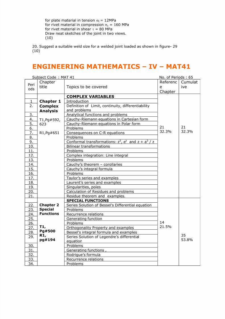
ENGINEERING MATHEMATICS – IV – MAT41
Subject Code : MAT 41 No. of Periods : 65
Periods
Chaptertitle Topics to be covered
ReferenceChapter
Cumulative
COMPLEX VARIABLES1 Introduction
2. Definition of Limit, continuity, differentiabilityand problems
3. Analytical functions and problems
4. Cauchy-Riemann equations in Cartesian form
5. Cauchy-Riemann equations in Polar form
6. Problems
7. Consequences on C-R equations
8. Problems
9. Conformal transformations: z2, ez and z + a2 / z
10. Bilinear transformations
11. Problems
12. Complex integration: Line integral
13. Problems14. Cauchy’s theorem – corollaries
15. Cauchy’s integral formula
16. Problems
17. Taylor’s series and examples
18. Laurent’s series and examples
19. Singularities, poles
20. Calculation of Residues and problems
21.
Chapter 1
ComplexAnalysis
T1,Pg#592,623
R1,Pg#651
Residue theorem and examples.
2132.3%
2132.3%
SPECIAL FUNCTIONS
22. Series Solution of Bessel’s Differential equation
23. Problems
24. Recurrence relations
25. Generating function
26. Problems
27. Orthogonality Property and examples
28. Bessel’s integral formula and examples
29. Series Solution of Legendre’s differentialequation
30. Problems
31. Generating functions ,
32. Rodrigue’s formula
33. Recurrence relations
34.
Chapter 2Special
Functions
T1,
Pg#500R1,
pg#194
Problems
1421.5%
3553.8%

7/21/2019 Encribd Com Mech 4 Sem Course Info Feb June 07
http://slidepdf.com/reader/full/encribd-com-mech-4-sem-course-info-feb-june-07 16/66
35. Orthogonality Property and problems
STATISTICS AND PROBABILITY
36. Curve fitting by the method of Least squares
37. Problems
38. Correlation and problems
39. Regression
40. Probability, conditional probability
41. Problems42. Baye’s rule and problems
43. Discrete and continuous random variables
44. PDF and CDF
45. Binomial distribution and problems
46. Poison distribution, Exponential distribution andproblems
47.
Chapter 3StatisticsandProbability
T1,Pg#733,780R1,Pg#1049R2,59,85,119,177,245
Normal distribution and problems
1218.5%
4772.3%
SAMPLING DISTRIBUTION
48. Sampling, Sampling distribution, Standard error
49. Type-I and Type-II errors and problems
50. Testing of hypothesis for means large samples
51. Testing of hypothesis for means small samples52. Level of Significance and problems
53. Confidence limits for means Large and Smallsamples
54.
Chapter 4Sampling
distributio
n
T1,Pg#822,R1,Pg#1104
Student’s t-distribution.
07
10.8%
54
83.1%
JOINT PROBABILITY DISTRIBUTION ANDMARKOV CHAINS
55. Concept of Joint Probability and Joint distribution
56. Discrete and independent random variables
57. Expectation and variance
58. Problems59. Introduction to Markov Chains
60. Probability vectors and problems
61. Stochastic Matrices and problems
62. Fixed points and regular Stochastic Matrices
63. Higher transition probabilities
64 Stationary distribution of regular Markov chains
65
Chapter 5Joint
Probability
Distributio
n &MarkovChains
R2,Pg#224282
Absorbing states
1116.9%
65100%
Literature
Book Type Code Title & Author Edition Publisher Year
Text Book T1 Higher EngineeringMathematics;B.S. Grewal
38th Khanna 2004
R1 Advanced EngineeringMathematics; ErwinKreyszig
8th Wiley 2001ReferenceBooks
R2 Schaum’s Outlines:Probability
2nd McGraw-Hill
2000

7/21/2019 Encribd Com Mech 4 Sem Course Info Feb June 07
http://slidepdf.com/reader/full/encribd-com-mech-4-sem-course-info-feb-june-07 17/66

7/21/2019 Encribd Com Mech 4 Sem Course Info Feb June 07
http://slidepdf.com/reader/full/encribd-com-mech-4-sem-course-info-feb-june-07 18/66
QUESTION BANK
COMPLEX ANALYSIS (20 marks)Analytic Functions:
1. Show that the function z z f =)( is continuous at every point but not differentiable at
any point.
2. Show that the function ( ) 2|| z z f = is continuous at every point but is not differentiable
at any point other than origin.
3. The necessary sufficient condition for the function f(z)= u + iv to be analytic is
y
v
x
u
∂∂
=∂∂
, y
u
x
v
∂∂
−=∂∂
4. If f (z) is analytic on an open set S and ( ) 0=′ z f for all S z ∈ show that f (z) is
constant.5. Show that an analytic function with constant real part is constant.6. Show that an analytic function with constant modulus is constant.7. If ( ) ivu z f += is analytic and is any differential function of x and y prove that
( ) 22222
|| z f vu y x
′⎪⎭
⎪⎬⎫
⎪⎩
⎪⎨⎧
⎟ ⎠
⎞⎜⎝
⎛ ∂∂
+⎟ ⎠
⎞⎜⎝
⎛ ∂∂
=⎟⎟ ⎠
⎞⎜⎜⎝
⎛
∂∂
+⎟ ⎠
⎞⎜⎝
⎛ ∂∂ ψ ψ ψ ψ
8. If ( ) ivu z f += is an analytic function, prove the following
(a) ( ) ( ) 222
2
2
2
||4|| z f z f y x
′=⎟⎟ ⎠
⎞⎜⎜⎝
⎛
∂
∂+
∂
∂
(b) ( ) ( ) ( ) 222
|||||| z f z f y
z f x
′=⎟⎟ ⎠
⎞⎜⎜⎝
⎛
∂∂
+⎟ ⎠
⎞⎜⎝
⎛ ∂∂
(c) ( ) 0||log2
2
2
2
=⎟⎟ ⎠
⎞⎜⎜⎝
⎛
∂
∂+
∂
∂ z f
y x
(d) If ( ) ivu z f += is analytic and φ is any differentiable function of x and y, prove that
( )
22222
|| z f vu y x′
⎪⎭
⎪
⎬
⎫
⎪⎩
⎪
⎨
⎧
⎟ ⎠
⎞
⎜⎝
⎛
∂
∂
+⎟ ⎠
⎞
⎜⎝
⎛
∂
∂
=⎟⎟ ⎠
⎞
⎜⎜⎝
⎛
∂
∂
+⎟ ⎠
⎞
⎜⎝
⎛
∂
∂ φ φ φ φ
(e) If ( ) ivu z f += is analytic, show that ( ) ( ) 222 |||| z f z f ′=∇
9. Prove that z z
F
y
F
x
F
∂∂∂
=∂
∂+
∂
∂ 2
2
2
2
2
4 Here F=F(x, y) z= x+ iy, iy x z −=
10. If f(z) = u +iv is analytic u and v satisfy Laplace’s equation, show that
02
2
2
2
=∂
∂+
∂
∂
y
u
x
u
2
2
x
v
∂
∂+
2
2
y
v
∂
∂= 0 i.e ., u & v are harmonic functions.
11. If f(z) = u + iv is analytic then the families of curves u= c1 and v= c2 here c1& c2 are constant are orthogonal.
12. Show that an analytic function constant modulus is constant.13. Find the analytic function f(z)=u + iv, given
(a) u =2x(1-y)(b) u = ex (x cosy – y siny)(c) x sinx cushy – ycosx sinhy(d) v=exsiny
(e) v=cosh2ycos2x
sinxsiny
+
(f) 22 y x
xvu
+=+

7/21/2019 Encribd Com Mech 4 Sem Course Info Feb June 07
http://slidepdf.com/reader/full/encribd-com-mech-4-sem-course-info-feb-june-07 19/66
PESIT
B.E. Mechanical 4th Semester Course Information
(g) y y
y
ee x
e x xvu
−
−
−−
−+=−
cos2
sincos
14. If θ ire z = and ( ) ( ) ( )θ θ ,, r ivr u z f += prove that
θ θ ∂∂
−=∂∂
∂∂
=∂∂ u
r r
vv
r r
u 1;
1
15. ( ) ( ) ( )θ θ ,, r ivr u z f += is analytic function, show that u and v satisfy the function
(a) 0112
2
22
2=
∂∂+
∂∂+
∂∂
θ
ϕ ϕ ϕ
r r r r
(b) 011
2
2
22
2
=∂
∂+
∂∂
+∂
∂
θ
u
r r
u
r r
u
(c) 011
2
2
22
2
=∂
∂+
∂∂
+∂
∂
θ
v
r r
v
r r
v
16. Find the analytic function ( ) ,ivu z f += given
(a) θ θ sin42cos2 −= r u (b) 0,2cos2
≠= r r
u θ
Complex Integration
1. Prove that ( ) ( ) ( )∫ ∫ ∫ ++−=c c c
vdxudyivdyudxdz z f
2. Prove that ( )∫ =c
dz z f 0
3. If c1,c2,c3…..cn are ‘n’ non overlapping simple closed curves within C and f(z) is analyticon these curves in the region bounded by them then prove that
( ) ( ) ( ) ( )∫∫∫∫ +++=
ncccc
dz z f dz z f dz z f dz z f .....
21
4. Verify the Cauchy’s theorem for the function ( ) 43 2 −+= iz z z f with c as the square
having vertices at 1 ± i , -1 ± i
5.
If f(z) is analytic within and on a simple closed curve c in the complex plane and a isany point c then prove that ( )
( )∫ −
=c
dza z
z f
ia f
π 2
1
6. If f(z) is analytic within and on a simple closed curve C and a is any point within C then
( ) ( )
( )∫ +−=
c
n
ndz
a z
z f
i
na f
12
!
π
7. Evaluate ∫ +
c
dz z
z,
12
where C is a simple closed contour enclosing the origin.
8. Evaluate ∫c
z
dz z
e3
where C is the circle |z|=1
9. Evaluate ∫ −+
c
dz z
z ,11
2
2where C is a circle of unit radius with center at (i) z= 1
(ii) z=-1
10. Obtain the Taylor’s and Laurent’s series for the function f(z)=( )( )21
12 ++ z z
for (a)|Z|<1
11. (b) 1<|z|<2 (c) |z|>2
12. Obtain Laurent’s expansion for ( )( )( )31
2
−−=
z z
z z f in the region (a) 1<|z|<3 (b) |z-
1|<2.

7/21/2019 Encribd Com Mech 4 Sem Course Info Feb June 07
http://slidepdf.com/reader/full/encribd-com-mech-4-sem-course-info-feb-june-07 20/66
PESIT
B.E. Mechanical 4th Semester Course Information
13. If C is a simple closed curve and f(z) is analytic within and on simple closed curve cexcept at finite points a1,a2,a3…..an inside c then prove that
( ) ( )∫ +++=c
n R R R Ridz z f ......2 321π here n R R R R ....,, 321 are residues of f(z) at a1,a2,a3,……an
14. Evaluate( )( )∫ −−
−
c
dz z z z
z
21
43 where C: |z|=3/2
15. ∫ −
+
c
dz z
z z
,1
22
2
where (i) C: |z|=2 (ii) C: |z-1|=1
16. Show that the transformation w = z2 transforms the circle | z-a | = c to a cardioid or alimacon.
17. Find the bilinear transformation that transforms the points z1 = 1, z2 = i, z3 = -1 ontothe points w1 = 2, w2 = i, w3 = -2. Find the fixed points of the transformation.
18. Find the images of (i) x-y = 1 (ii) x2 – y2 = 1 under the transformation w = z2.
BESSELS FUNCTIONS: (10 marks)
1. Find the series solution of Bessel's differential equation.2. Show that y = c1 Jn(kx ) + c2 J-n (kx) is the solution of x2 y2 + xy1 + (k2 x2 - n2)y =0.3. Verify that y = xn Jn(x) is the solution of x y2 +(1-2n)y1 + xy =0.
4. Show that (a) J ½ (x) = xπ
2Sinx (b) J -½ (x) =
xπ
2Cosx.
5. Show that 2n J n(x) = x [ ] (x)1J(x)1J ++ nn-
6. Show that J n'(x) = x [ ] (x)1J-(x)1J +nn-
7. Show that [ ])( x J xdx
d n
n = xn J n-1 (x) .
8. Show that [ ])( x J xdx
d n
n− = x-n J n+1 (x) .
9. Show that (a) J 3/2 (x) = xπ
2{(Sinx )/x - cosx }
(b) J --3/2 (x) = xπ
2{(Cosx)/x +sinx}
10. Show that [ ]).()( 1 x J x J xdx
d nn − = x[ J2 n (x) .- J2 n-1 (x)]
11. Show that cos (x sinθ) = J0(x) +2ΣJ2n(x)cos 2nθ 12. Show that sin (x sinθ) = 2ΣJ2n-1(x)sin (2n-1)θ
13. Prove that J n(x) = θ θ θ π
d xn )sincos(1∫ −
14. State and prove orthogonal property of Bessel's functions.
15. Show that 220
0
1
)(ba
dxbx J e ax
+=∫
∞−
16. Prove that ( ) ( ) ( ),xJ1J nn
xn −=− where n is a positive integer.
LEGENDRE POLYNOMIALS: (10 marks)
1. Find the series solution of Legendre's differential function.2. Show that (a)Pn (1) = 1 (b)Pn (-x) = (-1) n Pn (x) . Hence deduce that Pn (-1) = (-1)n
3. Express 3 - x + 2x2 + 2x3 + x4 in terms of Legendre’s polynomials.4. By using Rodrigue’s formula verify that Pn (x) satisfies Legendre’s differential equation.

7/21/2019 Encribd Com Mech 4 Sem Course Info Feb June 07
http://slidepdf.com/reader/full/encribd-com-mech-4-sem-course-info-feb-june-07 21/66
PESIT
B.E. Mechanical 4th Semester Course Information
5. Show that Pn (x) = θ θ π
π
d x x∫ ⎥⎦⎤
⎢⎣⎡ −±
0
2 cos11
6. Show that [ (2n+ 1) x Pn (x)] = (n+1) Pn+1 (x) + n Pn-1 (x)7. Show that Pn (x) = xP'n (x) - P'n-1 (x)8. Show that Pn (x) = P'n+1 (x) - 2x P'n (x) + P'n-1 (x)
9. Show that
)32)(12)(12(
1)(n2ndx(x)1.P(x)1.P
1
1
2
++−
+=−+∫
− nnn
nn x
10. Show that)14(
2ndx(x)1.P(x).P
2
1
1 −
=−∫−
nnn x
11. Show that)12(
2ndx(x).P'(x).P
1
1−
=∫−
nnn x
12. Prove that ( ) ( )nn
n
nn xdx
d
n xP 1
!2
1 2 −=
13. Express 543 23 +−+ x x x in terms of Lagendre’s Polynomials.
14. Prove that ( ) ( ) ( ) xnP x xP xP nnn 11''
−− +=
STATISTICS: (10 marks)
1. Fit the straight line of the form y= a + bx to the given datax: 0 5 10 15 20 25
y: 12 15 17 22 24 30
2. Fit a parabola cbxax y ++= 2 to the following data.
x: 20 40 60 80 100 120
y: 5.5 9.1 14.9 22.8 33.3 46.03. Fit a curve of the form y=axb for the data
x: 1 2 3 4 5 6
y: 2.98 4.26 5.21 6.1 6.8 7.5
4. The following table gives the marks obtained by a student in two subjects in ten tests.Find the coefficient of correlation.
Sub A : 77 54 27 52 14 35 90 25 56 60Sub B: 35 58 60 40 50 40 35 56 34 42
5. Show that there is a perfect correlation between x & y .x: 10 12 14 16 18 20y: 20 25 30 35 40 45
6. A computer while calculating the correlation coefficient bet x & y from 25 pairs ofobservations got the following constants n = 25, Σ x = 125, Σ x2 = 650, Σ y = 100,Σy2 = 460& Σ xy = 508. Later it was discovered it had copied down the pairs (8, 12) &(6, 8) as (6, 14) & (8, 6) respectively. Obtain the correct value of the correlationcoefficient.
7. If θ is the angle between two regression lines show that
22x
yx2 r -1
tan y
r σ σ
σ σ θ
+= and explain the significance when r = 0.
8. Find the lines of regression for the following data:x: 1 2 3 4 5 6 7 8 9 10y; 10 12 16 28 25 36 41 49 40
509. If the mean of x is 65, mean of y is 67, σx = 7. 5, σx = 3.5 & r = 0.8 find the value of x
corresponding to y= 75 & y corresponding to x = 70.

7/21/2019 Encribd Com Mech 4 Sem Course Info Feb June 07
http://slidepdf.com/reader/full/encribd-com-mech-4-sem-course-info-feb-june-07 22/66
PESIT
B.E. Mechanical 4th Semester Course Information
10. The two regression lines are x = 4y + 5 & 16y = x + 64 find the mean values of x, y& r.
11. In a partially destroyed laboratory record of correlation data only the following resultsare legible. variance of y is 16, regression equations are y = x + 5, 16x = 9y - 94,find the variance of x.
12. Fit a straight line to the data:(a) x: 0 1 2 3 4
y: 1 1.8 3.3 4.5 6.3
(b) x: 1 2 3 4 5y: 14 13 9 5 2
13. Fit a second degree parabola of the form y = ax2 + bx + c for the data:x: 1 2 3 4 5y: 1.8 5.1 8.9 14.1 19.8 . Estimate y for x = 2.5.
14. Fit an exponential curve of the form y = abx, for the following data:x: 1 2 3 4 5 6 7y: 87 97 113 129 202 195 193. Estimate y for x = 8.
PROBABILITY: (10 marks)
1. Define a sample space and probability of an event.. When are two events said to be(a) mutually exclusive (b) mutually independent.
2. If A & B are events P(A) = ½, P(B) = 1/3, P(A∩B) = 1/4,find (a) P(A/B) (b) P(B/A) (c) P(A∪B) (d) P(Ac)
3. An experiment succeeds twice as often as it fails. Find the chance that in the next 6trials there will be at least 4 successes.
4. A class consists of 6 girls & 10 boys If a committee of 3 is chosen at random find theprobability that (a) exactly 2 boys are selected (b) at least 1 boy is selected (c) exactly2 girls are selected.
5. A certain problem in mathematics is given to 4 students for solving. The probabilities ofsolving the problem individually are ½, 1/3, ¼, & 1/5 respectively. Find the probabilitythat (a) the problem is solved (b) the problem is solved exactly by one of them.
6. The chance that a doctor will diagnose a disease correctly is 60%. The chance that apatient will die after correct diagnosis is 40% and the chance of death after wrong
diagnosis is 70%. If a patient dies what is the chance that his disease was not diagnosedcorrectly.
7. Find the probability that a leap year selected at random will contain 53 Fridays.8. Four cards are drawn from a pack of 52 cards without replacement. Find the probability
that (a) they are all of different suits (b) no 2 cards are of equal value.9. State & prove Baye's theorem.10. Define (a) a random variable (b) Discrete and continuous random variable11. Define probability mass function and probability distribution function for a discrete
random variable.12. Define Geometrical distribution, uniform distribution, Exponential distribution.13. 3 machines A, B & C manufacture 40%, 50% & 10% of the total production of a factoryrespectively. The percentage of defective items produced by A, B & C are 2, 4, & 1.5respectively. An item is chosen at random & is found to be defective. Find the probability
that it was a product of C.4
14. There are 3 bags which contains 1 white, 2red & 3 green, 2 white, 3 red & 1 green and3 white, 1 red & 2 green marbles respectively. 2 marbles are drawn from a bag chosenat random and they are found to be 1 white & 1 red. Find the probability that the ballscame from the second bag.
15. Obtain the mean and variance for the following distributions: Binomial, Poisson,Exponential and Normal.
16. The probability of a man hitting a target is 1/3.(a) If he fires 5 times what is the probability of hitting a target at least twice.(b) How many times must he fire so that the probability of hitting a target

7/21/2019 Encribd Com Mech 4 Sem Course Info Feb June 07
http://slidepdf.com/reader/full/encribd-com-mech-4-sem-course-info-feb-june-07 23/66
PESIT
B.E. Mechanical 4th Semester Course Information
at least once is more than 90%.17. A cricket team has probability 2/3 of winning whenever it plays. If it plays 4 games, find
the probability that it wins (i) 2 games (ii) at least one game.18. A group of 20 airplanes are sent on an operational flight. The chance that an aero plane
fails to return from the flight is 5 %. Find the probability that (a) one plane does notreturn (b) at the most 5 planes do not return.
19. The probability that an individual suffers a bad reaction from a certain injection is 0.001.Determine the probability that out of 2000 individuals (a) exactly 3 (b) more than 2
individuals will suffer a bad reaction.20. Given that 2% of the fuses manufactured by a firm are defective, find the probability
that a box containing 200 fuses has (a) at least 1 defective fuse (b) at most 3 defectivefuses.
21. If the probability that a target is destroyed on any one shot is 0.5. What is theprobability that it will be destroyed in the 6th shot only and not before.
22. If the probability of the birth of a child with a defective heart in a certain city is 0.01.What is the probability that the 8th child born is the first one to have a defective heart?
23. On a certain city transport route, buses ply every 30 minutes between 6 a.m. & 10 p.m.If a person reaches a bus stop on this route at a random time during this period, what isthe probability that he will have to wait for at least 20 minutes?
24. The duration of time that an overhead tank will serve without refilling is found to followan exponential distribution with mean 10 days. Find the probability that (i) it needsfilling within 8 days & (ii) it will serve for more than 10 days.
25. Find the mean & S.D of a normal distribution of marks in an examination where 44% ofcandidates obtained below 55 & 6% above 80 and rest between 55 & 80.
26. The mean marks of 1000 students is 34.4 & S.D 16.5.Assuming that the marks arenormally distributed find the no. of students obtaining marks (i) bet 30 & 60 (ii) bet 70& 80.(iii) below 20 (iv)above 80.
27. A quality control engineer inspects a random sample of 3 batteries from each lot of 24car batteries that is ready to be shipped. If such a lot contains 6 batteries with slightdefects, what are the probabilities that an inspectors sample will contain(i) none of the batteries with defects (ii) only one of the batteries with defects(iii) at least 2 of the batteries with defects.
28. Among 300 employees of a company 240 are union members while the others are not.
If 8 employees are chosen by lot to serve on a committee, find the probability that 5 ofthem will be union members.
29. Find E(x) & V(x) for the following probability distribution:x: 3 4 5 6 7 8 9p: 0.05 0.12 0.20 0.24 0.17 0.14 0.008
30. A distributor makes a profit of $20 on an item. If it is shipped from the factory in perfectcondition and arrives on time but it is reduced by $2 if it does not arrive on time & $12regardless of whether it arrives on time if it is not shipped from the factory in perfectcondition. If 70% of such items are shipped in perfect condition and arrive on time, 10%are shipped in perfect condition but do not arrive on time and 20% are not shipped inperfect condition what is the distributors expected profit per item.
31. If a dealers profit in units of $1000 on a new automobile can be looked upon as a
random variable X having the density function f(x) = ⎩⎨⎧ <<−
elsewhere , 0
1x0 ),1(2 x
Find the
average profit per automobile and also E(X2).
32. Show that (i) E(c) = c (ii) E (aX + b) = a E(X) + b (iii)V(X) = E(X2) - E(X)2 .(iv) V(c) = 0 (v) V (aX + b) =a2 V(X).
33. The distribution of 2 independent random variables X & Y are given below:X 0 1 Y 1 2 3P(X) 0.2 0.8 P(Y) 0.1 0.4 0.5Find the joint probability distribution of X & Y.

7/21/2019 Encribd Com Mech 4 Sem Course Info Feb June 07
http://slidepdf.com/reader/full/encribd-com-mech-4-sem-course-info-feb-june-07 24/66
PESIT
B.E. Mechanical 4th Semester Course Information
34.The following table gives the joint probability distribution of 2 random variablesX &Y
X/Y -1 0 1
-1 0 0.2 0
0 0.1 0.2 0.1
1 0.1 0.2 0.1
Find the conditional probability of X given Y = 0.35. The joint distribution of two random variables X and Y is given by the following table.
X / Y -4 2 7
1 1/8 1/4 1/8
5 ¼ 1/8 1/8
Determine (i) the marginal distributions of X and Y. (ii) E (X) and E(Y) (iii) are X and Yindependent random variables?
Sampling Distribution: (20 marks)1. A Sample of 5 measurements of the diameter of a sphere was recorded as 6.33, 6.37,
6.36, 6.32, 6.37mm. Find unbiased and efficient estimates of (i) the populationmean (ii) the population variance.
2. For the frequency distribution given below find the unbiased and efficient estimates forthe mean and variance
Xi 60 61 62 63 64 65 66 67 68
f i 02 00 15 29 25 12 10 04 03
3. The sample mean of a population was recorded as 184.67 with a probable error of0.236. Find the 99.74% confidence limits for the true (population) mean.
4. The S.D of life time of 200 electric bulbs was computed to be 80 hours. Find (i) 95%&
(ii) 99% confidence limits for the S.D of all such bulbs.5. How large a sample should one take in order to be (i) 99% & (ii) 99.74 % confident that
a population S.D will not differ from a sample S.D by more than 2%.6. A die is thrown 9000 times and a draw of 3 or 4 observed 3240 times. Show that a die
cannot be regarded as an unbiased one. Also find the limits between which theprobability of throw of 3 or 4 lies at 99.74% level of confidence
7. A mean of a sample of size 900 is 3.4.Can the sample be reasonably as a true randomsample for a large population with means 3.25 and S.D 1.61
8. Ten screws are chosen at random from a population and their lengths are found as (inmms) 63,63,66,67,68,69,70,70,71,71. On the basis of this information can we say thatthe mean length in the population is 66mm at 95%confidence level?
9. Find 99% confidence limits for the correlation coefficient, which is computed to be 0.60from a sample of size 28
TESTING OF HYPOTHESIS:
1. An electrical firm manufactures light bulbs that have a length of life that isapproximately normally distributed with a mean of 500 hours and a S.D of 40hours. Test the hypothesis Ho: μ ≠ 800 of a random sample of 30 bulbs has anaverage life of 788 hours. Use 5 % level of significance.
2. Test the hypothesis that the average content of containers of a particular lubricantis 10 liters if the contents of the random sample of 10 containers are 10.2, 9.7,10.1, 10.3, 10.1, 9.8, 9.9, 10.4, 10.3 & Use 0.01 level of significance and assumethat the distribution of contents is normal.

7/21/2019 Encribd Com Mech 4 Sem Course Info Feb June 07
http://slidepdf.com/reader/full/encribd-com-mech-4-sem-course-info-feb-june-07 25/66
PESIT
B.E. Mechanical 4th Semester Course Information
3. A random sample of size n1 = 2.5 taken from a normal population with a S.D σ1 =5.2 has a mean .811 = x A second random sample of size n2 = 36 taken from a
different normal population with a S.D σ2 = 3.4 has mean 762 = x . Test the
hypothesis that μ1 = μ2 against the alternative μ1 > μ2 at 5% level of significance.4. A large automobile manufacturing company is trying to decide whether to purchase
brand A or B tyres for its new models. To help arrive at a decision, an experiment isconducted using 12 of each brand. The tyres are run until they wear out. Theresults are
Brand A : kmsskms x 5100,900,37 11 ==
Brand B : kmsskms x 5900,800,39 22 == .
Test the hypothesis at the 0.05 level of significance that there is no difference in the 2brands of tyres. Assume the population to be approximately normally distributed.
5. Explain the following a) Tests of Hypothesis b) Type I and Type II errors findmean and variance of the Chi square distributions.
JOINT PROBABILITY AND MARKOVCHAINS (20 marks)
1. Show that the vector (y, x) is a fixed point of the stochastic matrix P= ⎥⎦
⎤⎢⎣
⎡
−
−
y y
x x
1
1
2. Find the unique fixed probability vector of the regular stochastic matrix
⎥⎥⎥
⎦
⎤
⎢⎢⎢
⎣
⎡
010
2/102/14/14/12/1
3. If P= ⎥⎦
⎤⎢⎣
⎡2/12/1
1 ois the transition matrix with initial probability distribution ( ) ( )3/2,3/10 = p .
Define and compute.(a) ( )21
3 p (b) ( )3
p (c) ( )2
3 p
4. A salesman’s territory consists of three cities A, B &C. He never sells in the same city onconsecutive days. If he sells in a city A, the next day he sells in city B. However if hesells in either B or C then the next day he is twice as likely to sell it in city A or in othercity. Show that in the long run he sells 40% of the time in the city A, 45% of the time incity B and 15% of the time in the city C
5. A software engineer goes to his workplace everyday by motorbike or by car. He nevergoes by bike on 2 consecutive days but if he goes by car on a day then he isequally likely to go by car or by bike the next day. Find the transition probability matrixfor the chain mode of transport he uses. If car is used on the first day of a week find theprobability that after 4 day s (i) bike is used (ii) car is used.
6. A gambler’s luck follows a pattern. If he wins a game, the probability of winning the nextgame is 0.6. However if he loses a game, the probability of losing the next game is 0.7.There is an even chance that he wins the first game. If so,
(a) Find the transition matrix M of the Markov process.(b) Find the probability that he wins the second game.(c) Find the probability that he wins the third game.
(d) Find out how often, in the long run, he wins.
Define stochastic matrix. Find the unique fixed probability vector for the regular stochastic
matrix
⎥⎥⎥⎥
⎦
⎤
⎢⎢⎢⎢
⎣
⎡
010
021
21
41
430

7/21/2019 Encribd Com Mech 4 Sem Course Info Feb June 07
http://slidepdf.com/reader/full/encribd-com-mech-4-sem-course-info-feb-june-07 26/66
PESIT
B.E. Mechanical 4th Semester Course Information
APPLIED THERMODYNAMICS – ME 43
(2 hours / week for both IV ‘A’ and IV ‘B’ sections)
Faculty :Dr.T.R.Seetharam
Lecture Topics To be Covered %Coverage
of
syllabus
1 – 2 Review of Basic Thermodynamics – Applications of I &II law for closed and open systems, Important property relations forideal gases, properties of pure substances ; Use of tables & charts Nil
3 – 6 Gas Power Cycles: Introduction; Air – standard cycles for IC engines –analysis of Carnot,Otto,Diesel & Dual- combustion cycles ; 08
7- 11 Gas Turbine Cycles – Simple Brayton cycle, modifiedBrayton cycle for improvement in work output & thermalEfficiency, deviations of practical cycles from ideal cycle 08
12 – 17 Vapour Power cycles- Carnot vapour power cycle and its limitations;Simple Rankine cycle; effects of pressure & temperature on performanceof Rankine cycles; modifications of simple Rankine cycle to increasenet work output & thermal efficiency – Reheat cycle, Regenerative cycle,types of feed water heaters used in regenerative cycles;Reheat-Regenerative cycle; practical vapour power cycles .
12
18 - 20 Refrigeration – Definition of Refrigeration, refrigerated space, refrigerantRefrigeration cycle, refrigeration effect; units of refrigeration effect – Tonof refrigeration; COP ; Carnot refrigerator – analysis and its limitations;Air refrigeration plant – Bell-Coleman / Reversed Brayton cycle; practicalair refrigeration cycles
06
21 - 23 Vapour compression refrigeration cycle – analysis, effects of sub-coolingand superheating on the performance ; desirable properties of refrigerantsfor vapour compression cycle; steam jet refrigeration
06
24 - 25 Psychometrics – Thermodynamics of air-water vapour mixture – definitionsOf moist air, dry air, specific humidity, relative humidity, dries – bulb and wet –bulb and dew point temperatures; adiabatic saturation temperature, saturatedunsaturated air, enthalpy of moist air, construction and use of psychometricchart
0426 - 28 Thermodynamic analysis of psychometric processes like heating, cooling
Heating & humidification, cooling and de-humidification, adiabatic mixingAir streams, summer and winter air conditioning
08

7/21/2019 Encribd Com Mech 4 Sem Course Info Feb June 07
http://slidepdf.com/reader/full/encribd-com-mech-4-sem-course-info-feb-june-07 27/66
PESIT
B.E. Mechanical 4th Semester Course Information
ME 43: Applied Thermodynamics
Tutorial 1: Problems on Gas Power Cycles
A. Problems on Carnot Cycle
1.1. A Carnot power cycle using air as the working substance, works between theemperature limits of 900 K and 300 K. The pressure limits are 60 bar and 1 bar. Find
(i) pressure and temperature at salient points of the cycle, (ii) heat supplied and heatrejected per unit mass of air, (iii) net work output and thermal efficiency, and (iii)mean effective pressure.
1.2. The maximum pressure and temperature in a Carnot cycle is limited to 20 bar and 400C. The volumetric ratio of isentropic compression is 6 and the volumetric ratio ofisothermal expansion is 1.5. The volume of air at the beginning of isothermalexpansion is 0.1 m3. Find (i) the minimum temperature in the cycle, (ii) Thermalefficxiency of the cycle, (iii) power output form the cycle if the number of cycles perminute is 200.
1.3. In an air standard Carnot cycle heat is transferred to the working fluid at 1110 k andheat is rejected at 273 K. The heat transfer to the working fluid is 105 kJ / kg. Theminimum pressure in the cycle is 1 bar. Determine (i) the thermal efficiency and (ii)the m e p.
1.4. A Carnot engine converts 1/6 of the heat input into work. When the temperature of thesink is reduced by 70 C, the efficiency of the cycle is doubled. Determine thetemperature of the source and the sink.
B. Problems on Otto Cycle
1.5. In an air standard Otto cycle the maximum and minimum temperatures are 1400 C and15 C respectively. The heat supplied is 800 kJ / kg. Calculate the compression ratioand the thermal efficiency. Also calculate the ratio of maximum pressure to the
minimum pressure in the cycle.
1.6. In an engine working on Otto cycle, the clearance volume is 50 cm3, while the strokevolume is 350 cm3. If the temperature at the commencement of the compressionprocess is 27 C and the maximum temperature in the cycle is 1000 C determine (i) thecompression ratio, (ii) cycle efficiency, (iii) net work output per unit mass of air and(iv) mep.
1.7. From the p-v diagram of an engine working on Otto cycle, it is found that the pressureinside the cylinder after 1/8th of the compression stroke is completed is 1.4 bar. After5/8th of the compression stroke is completed, the pressure was found to be 3.5 bar.The maximum temperature in the cycle is limited to 1000 C. Determine (i) thecompression ratio,(ii) air standard efficiency, (iii) net work output per unit mass of air,
(iv) mep, (v) compression ratio corresponding to maximum work output, (vi)maximum work output and (vii) thermal efficiency corresponding to maximum workoutput. Assume that the minimum temperature in the cycle to be 27 C.
1.8. An engine working on Otto cycle has a volume of 0.5 m3 , a temperature of 27 C and apressure of 1 bar at the beginning of the compression process. At the end of thecompression process the pressure is 10 bar. Heat added is 200 kJ /kg. Determine (i)percent clearance, (ii) air standard efficiency, (iii) MEP, (iv) power developed by theengine if there are 200 cycles per minute.

7/21/2019 Encribd Com Mech 4 Sem Course Info Feb June 07
http://slidepdf.com/reader/full/encribd-com-mech-4-sem-course-info-feb-june-07 28/66
PESIT
B.E. Mechanical 4th Semester Course Information
1.9. Derive an expression for the air standard efficiency of a cycle similar to Otto cycleexcept that the compression process is isothermal, in terms of the compression ratio,maximum cycle temperature ratio and the ratio of specific heats.
1.10. The compression curve in an Otto cycle may be approximated by the equation pV1.35 =constant. The expansion curve is isentropic. The maximum temperature in the cycle is1000 K. If the temperature of air at entry to the engine is 27 C, find the thermalefficiency and the relative efficiency based on the air standard Otto cycle. The
compression ratio is 7.5. Assume the specific heats of air to be constant and γ = 1.4.
Tutorial 2 : Gas Power Cycles (continued)
C. Problems on Diesel Cycles
2.1. The compression ratio of an air standard diesel cycle is 14 and the cut-off ratio is2.2. At the beginning of the cycle the pressure and temperature of air are 0.98 bar and 300
K respectively. Find (i) pressure and temperatures at salient point of the cycle, (ii) thenet work output per unit mass of air, (iii) thermal efficiency, (iv)MEP, and (iv) specificair consumption in kg/kWh.
2.2. An air standard diesel cycle has a compression ratio of 18 and the heat transfer to theworking fluid is 1800 kJ/kg. At the beginning of the compression process the pressureand temperatures are 1 bar and 300 K respectively. Determine (i) air standardefficiency, and (ii) MEP
2.3. An oil engine works on a diesel cycle with compression ratio of 20. Heat addition takesplace up to 10 % of the stroke. Initial pressure and temperature of air are 1 bar and27 C. Assume that the compression process is according to the law pv1.32 = constantand the expansion process is according to the law pv1.30 = constant. The bore andstroke of the engine are 16 cm and 20 cm respectively. Find (i) the pressure andtemperature at salient points of the cycle, (ii)MEP, (iii) thermal efficiency, (iv) relativeefficiency
2.4. In a diesel cycle, the pressures at two points on the compression curve are 1.7 bar and13.4 bar, respectively, corresponding to positions where 3/10th and 9/10th of thestroke have been executed. Find the compression ratio if the compression andexpansion indices are 1.38 and 1.3 respectively. If the cut-off ratio is 1.8, determinethe cycle efficiency and the relative efficiency based on the air standard cycle.
2.5. In an air standard diesel cycle, air is compressed isentropically from 26 C and 105 kPato 3.7 kPa. The entropy change during heat rejection is − 0.6939 kJ/(kg – K).Determine (i) heat supplied per kg of air, (ii) thermal efficiency, (iii) maximumtemperature in the cycle, and (iv) temperature at the start of the heat rejection.
D. Problems on Dual Combustion cycles
2.6. The compression and expansion ratio of an oil engine working on a dual cycle is 9 and5 respectively. The initial pressure and temperature are 1 bar and 30 C. The heatadded at constant pressure is twice that at constant volume. The cyclider bore is 250mm and the stroke is 400 mm. Determine (i) thermal efficiency and (ii) MEP
2.7. The maximum and the compression pressures in a dual cycle are 64 bar and 32 barrespectively. The compression curve is polytropic with index n = 1.35. The pressure inthe cycle after 1/3rd of the compression stroke is completed is 1.65 bar. If 60 % of theenergy addition occurs at constant volume while 40 % occurs at constant pressure,find

7/21/2019 Encribd Com Mech 4 Sem Course Info Feb June 07
http://slidepdf.com/reader/full/encribd-com-mech-4-sem-course-info-feb-june-07 29/66
PESIT
B.E. Mechanical 4th Semester Course Information
(i) the compression ratio, (ii) the suction pressure, (iii) work output from the cycle ifthe expansion index is 1.34, and (iv) thermal efficiency.
2.8. A diesel engine works between the temperatures of 1250 C and 25 C. The energyaddition during combustion is 550 kJ /kg. A dual combustion cycle operates betweenthe same temperature limits, and has the same total energy addition as for dieselcycle except that this energy is equally divided between the constant volume andconstant pressure processes. Compare the efficiencies of the two cycles. Hence show
using T-s diagram that the diesel cycle is more efficient than the dual cycle under thesame maximum and minimum temperatures as well as the same amount of heataddition.
2.9. In a dual cycle, two thirds of the total energy added occurs at constant volume.. If thecompression ratio is 15, and the maximum pressure in the cycle is 53 bar,compute(i)the temperatures at the salient points of the cycle, and (ii) thermalefficiency. Assume standard conditions of air at the start of the compression process.
2.10. The compression ratio for an engine working on dual cycle is 7. The cylinder diameteris 25 cm and the stroke is 30 cm. The air at the start of the compression is at 101 kPaand 20 0C. At the end of the constant volume process, the pressure is 5600 kPa. Ifheat is added at constant pressure during 3 percent of the stroke, compute (i) the network output from the cycle, (ii) the thermal efficiency, (iii) the amount of heat added,and (iv) the mean effective pressure
Tutorial 3: Gas Power Cycles (Gas Turbine Cycles)
3.1. An air standard Brayton cycle has air enter the compressor at 27 C and 100 kPa. Thepressure ratio is 10 and the maximum allowable temperature is 1350 K. Determine (i)pressure and temperature at salient points of the cycle, (ii) compressor and turbinework per unit mass of air, (iii) net work output and work ratio, (iv) thermal efficiencyand specific air consumption in kg/(kWh).
3.2.The pressure ratio of an open gas turbine cycle is 6.The compressor inlet conditions are1 bar and 15 0C. The maximum temperature in the cycle is 800 0C. The compressorefficiency is 85 %, the turbine efficiency is 90 % and the combustion efficiency is 95 %.There is a pressure drop of 2 % of the inlet pressure in the combustion chamber. Thecalorific value of the fuel used is 42,000 kJ/kg.Assuming that cp and γ remains samethroughout the cycle and equal to those values for air determine (i) Net work outputper unit mass of air, (ii) Air-fuel ratio, (iii) thermal efficiency of the plant, (iv) specificfuel combustion in kg / kWh, and (v) power output form the plant for a mass flow rateof air of 1.0 kg / s.
3.3. The isentropic discharge temperature for the air flowing out of a compressor is 195 0Cwhile the actual temperature is 240 0C. The conditions of air at compressor inlet are 1bar and 17 0C. If the air-fuel ratio in the combustion chamber is 75:1 and net power
output is 650 kW, compute (i) the isentropic efficiencies of the compressor and turbineand (ii) the overall cycle efficiency. Assume that the plant consumes 5.2 kg/min of fuelsupplied and the calorific value of the fuel used is 42,000 kJ/kg.Also assume that for aircp = 1.005 kJ/kg – K and γ = 1.4 and cp = 1.148 kJ/kg – K and γ = 1.333 for productsof combustion.
3.4. Determine the thermal efficiency of a gas turbine cycle having two stages ofcompression and two stages of expansion. The overall pressure ratio of the cycle is 4.Air enters both the stages of compression at 15 0C and enters both the stages ofturbine at 900 0C. If an ideal regenerator is incorporated in the cycle to heat the aircoming out of the second stage compressor, what would be the improvement in the

7/21/2019 Encribd Com Mech 4 Sem Course Info Feb June 07
http://slidepdf.com/reader/full/encribd-com-mech-4-sem-course-info-feb-june-07 30/66
PESIT
B.E. Mechanical 4th Semester Course Information
thermal efficiency of the cycle. What would be the net work output and cycle efficiencyif the compressor and expansion stages have efficiencies of 80 % each and theregenerator effectiveness is 75 %
3.5. Determine the specific work output, specific fuel consumption and cycle efficiency for agas turbine power plant using a regenerator having the following specifications.
Compressor pressure ratio 4.0
Turbine inlet temperature 1100 KIsentropic efficiency of compressor 0.85Isentropic efficiency of turbine 0.87Mechanical transmission efficiency 0.99Combustion efficiency 0.98Heat exchanger effectiveness 0.80Pressure losses :-(i) Combustion chamber 2 % of compressor deliverypressure(ii) Heat exchanger air side loss 3 % of compressor deliverypressure(iii) Heat exchanger gas side loss 0.04 bar
3.6. An ideal gas turbine power plant operates with ‘m’ number of stages of compressionand ‘n’ number of stages of exp[ansion. The maximum temperature permitted in theplant is Tmax. Pressure ratios in all the compressor stages are equal and expansionratios in all the turbine stages are equal. The intercoolig between the compressorstages is perfect and the working fluid is reheated to Tmax in between the stages ofexpansion.If ‘t’ represents the maximum cycle temperature ratio in the cycle show that
t = (r a) (m+n)/mn
where r = ratio of maximum pressure to minimum pressure in the plant anda = (γ – 1) / γ.
3.7. A Brayton cycle works between 1 bar, 300 K and 5 bar, 1250 k. There are two stagesof compression with perfect intercooling and two stages of expansion. The work outputfrom the first stage turbine is used to drive the two compressors. The air from the firststage turbine is reheated back to 1250 K and then expanded in the second stage.Calculate the power output from the plant and the cycle efficiency. What would be thepower output and cycle efficiency if an ideal regenerator is incorporated in the cycle?
3.8.In a gas turbine unit with two-stage compression and two-stage expansion, the gastemperature at the entry to both the turbines is the same. The intercooler in betweenthe two stages of compression has an effectiveness of 83 %. The maximum andminimum temperatures in the cycle are 25 C and 1000 C. The low and high pressurelimits are 1.02 bar and 7 bar. Assuming that the intermediate pressure between the
two stages of compression is same as that at the exit of the first stage expansion andequal to the geometric mean of the high and low pressures of the unit, calculate (i) theair fuel ratio if the calorific value of the fuel used is 38650 kJ/kg, (ii)power output foran air flow rate of 1 kg/s. Assume that a regenerator with an effectiveness of o.80 isincorporated in the cycle. The pressure drop through the regenerator and firstcombustion chamber is 0.1 bar, while the pressure drop through the secondcombustion chamber is 0.05 bar. The exhaust pressure of the second turbine is 1.15bar. The pressure drop through the intercooler is negligible. Assume the compressorefficiency is 0.84 for both trhe stages and turbine efficiency is 0.89 for both the stages.

7/21/2019 Encribd Com Mech 4 Sem Course Info Feb June 07
http://slidepdf.com/reader/full/encribd-com-mech-4-sem-course-info-feb-june-07 31/66
PESIT
B.E. Mechanical 4th Semester Course Information
3.9. In a closed cycle gas turbine plant, the compressor inlet and exit conditions are 5 barand 32.5 bar respectively. After passing through a regenerator with an effectiveness of0.83, the air is heated in a nuclear reactor to 945 K. The pressure drop in theregenerator and the reactor reduces the air pressure at the turbine inlet to 31.5.bar.After expansion to 5.25 bar in the turbine with an efficiency of 0.88, the air passesthrough the regenerator and a cooler, before being ready to enter the compressor (efficiency = 0.80) again at 20 C. Calculate (a) the cycle thermal efficiency, (b) theturbine and compressor power, and (c) the heat transfer at the reactor and the net air
flow rate if the net power output from the plant is 650 kW.
3.10. The schematic diagram of a gas turbine power plant is shown in Fig. P1.30.The statesof the flowing gas at various points along the circuit are numbered. The following arethe data referring to these states.
T1 = 20 C; Pressure ratio for each compressor = 3.5; Compressor efficiencies = 0.84;Intercooler effectiveness = 0.95; pressure ratio across the intercooler = 0.96;pressure ratio across the regenerator = p5 / p4 = 0.95; regenerator effectiveness =0.85; enthalpy of combustion of fuel = − 42,000 kJ/kg; combustion efficiency = 0.98;pressure ratio across the combustion chamber = p6 / p5 = 0.97; T6 = 1110 K; T8 =1050 K; turbine efficiencies = 0.88. Pressure drop for gases leaving the turbine andflowing back through the regenerator = p10 / p9 = 0.97; pressure drop across intake =p1 / p∞ = p∞ / p10 = 0.98.Calculate (a) T2,T3,T4,T5,T7 and T9, (b) the total work required to drive the
compressors and hence the output of turbine T1, (c) the air fuel ratios at the twocombustion chambers,(d) the net work output from the plant, (e) the overall cyclethermal efficiency, and (f) the specific power output from the plant in kW/(kg – s) ofair flow through the compressor.
Tutorial 4 : Vapour Power Cycles
C1 C2 T1 T2
CC1
CC2Regenerator
Inter cooler
1
23
4
6
7 89
10
Fig. P 4.4 : Figure for problem P1.30

7/21/2019 Encribd Com Mech 4 Sem Course Info Feb June 07
http://slidepdf.com/reader/full/encribd-com-mech-4-sem-course-info-feb-june-07 32/66
PESIT
B.E. Mechanical 4th Semester Course Information
4.1. A simple Rankine cycle dry saturated steam at 20 bar enters the turbine and thecondenser pressure is 1 bar. Determine (i) the pump work, (ii) the turbine work, (iii)the net work out put, (iv) the thermal efficiency, (v) quality of steam entering thecondenser and (vi) steam rate in kg/kWh. What would be the corresponding valueswhen the condenser pressure is decreased to 0.1 bar other things being the same.
4.2. Steam conditions at the boiler exit are 10 bar and 300 C. In the pipe line between theboiler exit and turbine inlet, there is an energy loss of 42 kJ/kg and a drop in pressure
of 0.2 bar. The steam expands in the turbine to a pressure of 0.09 bar at the turbineexit, the efficiency of the turbine being 0.86. Find the stream conditions at the turbineinlet, the actual enthalpy drop across the turbine and the final condition at dischargefrom the turbine.
4.3. In a reheat cycle, the boiler exit conditions are 25 bar and 300 C. the exit pressure ofsteam at the end of the first turbine is 5 bar. The steam is reheated to 300 C before itis expanded in the second turbine to 0.05 bar. Assumiing the high and low pressureturbines to have efficiencies of 0.87 and 0.85 respectively, determine (i) the thermalenergy input in the reheater, (ii) the overall thermal efficiency of the cycle, (iii) specificsteam consumption in kg/kWh, and (iv) net power output from the cycle for a massflow rate of 1.0 kg/s.
4.4. Steam at 50 bar and 350 C expands to 12 bar in a high pressure stage and is drysaturated at the stage exit. This is now reheated to 280 C without any pressure drop.The reheated steam expands in an intermediate stage and again emerges as drysaturated steam at a lower pressure, to be reheated a second time to 280 C. Finally,the steam expands in a low pressure turbine to 0.05 bar. Assuming the work output isthe same for the high and intermediate stages, and the efficiencies of the high and lowpressure stages are equal, find: (i) efficiency of the high pressure stage, (ii) pressureof steam at exit of the intermediate stage, (iii) total power output from the threestages for a mass flow rate of 1.0 kg/s, (iv) condition of steam entering the condenser,and (v) thermal efficiency of the cycle
4.5. Determine the improvement in thermal efficiency which will result if one stage of
regenerative feed heating is added to a simple Rankine cycle which has the boiler exitcondition of 14 bar and 300 C and a condenser pressure of 0.08 bar. Steam for feedheating is to be extracted at 2.0 bar.
4.6. In a reheat – regenerative steam power plant cycle, the HP turbine receives steam at20 bar and 300 0C. After expansion to 7 bar, the steam is reheated to 300 0C and thenit expands in an intermediate stage to 1 bar. A fraction of the steam is now extractedfor feed water heating, while the remaining steam expands in a LP turbine to a finalpressure of 35 mm of mercury. If the efficiencies of high, intermediate and lowpressure stages are respectively 0.90, 0.88, and 0.87, determine the overall cycleefficiency of the plant.
4.7. Steam expands in a turbine from 30 bar, 360 0C to a condenser pressure of 0.04 bar.
The isentropic efficiency is 0.82 and the steam condition at any point in the turbinemay be assumed to be on a straight line joining the initial and final states, drawn on anh – s chart. During expansion steam is bled at two stages where the pressures are 5bar and 0.7 bar respectively. The heaters are of closed type, the condensed steamfrom the high pressure heater is being led to the steam space of the low pressureheater through a steam trap.The condensed steam from the low pressure heater is fedto the intake of the feed pump through a drain cooler. Assuming the feed water in eachheater to be heated to the saturation temperature corresponding to the bled steampressure for that heater and that the temperature of the condensate from the heatersat the exit of the drain cooler is 30.2 0C, find the overall thermal efficiency of the plantand the specific steam consumption..

7/21/2019 Encribd Com Mech 4 Sem Course Info Feb June 07
http://slidepdf.com/reader/full/encribd-com-mech-4-sem-course-info-feb-june-07 33/66
PESIT
B.E. Mechanical 4th Semester Course Information
4.8. In a two-stage regenerative feed heating system, the steam conditions at the turbineinlet and exit are 20 bar, 320 0C and 0.08 bar. The low pressure feed water heaterreceives steam at 0.9 bar and heats the feed water from 33.5 0C to 89.5 0C. Thecondensed steam is cascaded back into the condenser through a steam trap.For thehigh pressure heater, steam is extracted at 4 bar and heats the water from 89.5 0C to140 0C. Its condensate is pumped by a drain pump into the boiler feed line. Find themass flow rates of steam to each feed water heater per kg of steam generated in the
boiler. If the total steam generation is 18,000 kg/h, find the power output of the plantin kW. Assume the turbine efficiency to be 0.82 and the condition of steam at anypoint in the turbine to be on a straight line on the h – s diagram connecting the steamstates at inlet and exit. Draw a schematic for the system and indicate all the salientpoints on the Mollier diagram. Also determine the overall cycle efficiency of the plantand specific steam consumption.
4.9. An ideal Rankine cycle with regenerative heating operates between the pressure limitsof 10 MPa and 40 kPa. Temperature of steam at turbine inlet is 500 0C. There are twoopen feed water heaters. On the basis of optimum design, determine (i) the pump workto turbine work, (ii) the ratio of heat rejection to heat addition, (iii) the mass of steambled out for each feed water heater per unit mass of steam generated in the boiler, and(iv) cycle thermal efficiency.
Tutorial 5 : Refrigeration Cycles
A . P r o b l e m s o n A i r R e f r ig e r a t i o n c y c le s
5.1. A reversed Carnot cycle is used for heating and cooling. The work supplied is 10 kW. Ifthe COP is 3.5 for cooling determine (a) the ratio of maximum temperature to minimumtemperature in the cycle , (b) refrigeration effect in tons and (c) COP if the cycle isused as a heat pump.
5.2. An ideal air refrigeration cycle has the following specifications:
Pressure of air at compressor inlet = 101 kPa;Pressure of air at turbine inlet = 404 kPa;Temperature of air at compressor inlet = −6 C;Temperature of air at turbine inlet = 27 C;Determine (i) The COP of the cycle, (ii) Power required to produce 1 ton ofrefrigeration, and (iii) air circulation rate per ton of refrigeration.
5.3 In an air refrigerating machine, the compressor takes in air at 1 bar and 10 C. Aftercompression to 5.5 bar, the air is cooled to 30 C before expanding it back to 1 bar.Assuming ideal conditions, determine (i) refrigeration effect per unit mass ofair,(ii)heat rejected by air per unit mass in the intercooler, and (ii) COP of the cycle, Inan actual plant using the above cycle, the air flow rate is 1700 kg / h and the relative
COP of the actual plant is 0.65. Determine the power required for the actual plant forthe same refrigeration effect
5.4:- An air refrigeration system is to be designed according to the following specifications:Pressure of air at compressor inlet = 101 kPa;Pressure of air at compressor exit = 404 kPa;Temperature of air at compressor inlet = − 6 C;Temperature of air at turbine inlet = 27 C;Isentropic efficiency of compressor = 85 %;Isentropic efficiency of turbine = 85 %;Relative pressure drop in each heat exchanger = 3 %

7/21/2019 Encribd Com Mech 4 Sem Course Info Feb June 07
http://slidepdf.com/reader/full/encribd-com-mech-4-sem-course-info-feb-june-07 34/66
PESIT
B.E. Mechanical 4th Semester Course Information
Capacity of the plant = 1 tonDetermine (a) COP of the cycle, (ii) Power required in kW, and (iii) air circulation rate
5.5:-An air refrigerator unit uses a reciprocating compressor and a reciprocating expander.5 kg / min of air at 30 C (ambient temperature is 25 C) and 4.8 bar expand behind apiston to 1 bar. The expansion is according to the law pv1.35= constant. Afterexpansion, the air enters a cold chamber where its temperature rises to 0 C and the itis compressed back to 4.8 bar according to the law pv1.28 = constant. Determine (a)
the power required to drive the unit if the mechanical efficiencies of the expander andthe compressor are both equal to 85 %, (b) capacity of the refrigerator in tons, (c)energy rejected by air to the ambient during the cooling process at 4.8 bar and (d) theactual COP of the plant.
5.6:-In an ideal air refrigeration cycle, air after compression in the compressor is firstcooled in an intercooler and then passed through a regenerative heat exchanger. It isthen expanded in a turbine and after expansion the air flows through the regenerativeheat exchanger where it exchanges heat with the air coming from the intercooler.Then the cold air is passed through the cold chamber before it enters thecompressor.(a) Draw the schematic layout of the plant.(b) obtain an expression forthe COP of the cycle in terms of the pressure ratio of the compressor and thetemperature ratio of the compressor inlet temperature to the turbine inlettemperature.
5.7 :- An air refrigeration unit takes in air from a cold chamber at 5 C and compresses itfrom 1 bar to 6.5 bar. The index of compression is 1.25. The compressed air is cooledto a temperature which is 10 C above the ambient temperature of 30 C before beingexpanded isentropically in an expander. Neglecting the clearance volume of thecompressor and expander find the COP and the amount of air circulation per minute if2000 kg of ice at 0 C is to be formed per day from water at 25 C. What will be thetonnage of the unit?
B . Pr o b l e m s o n V a p o u r Com p r e s s io n R e f r i g e r a t i o n Cy c l e s
5.8:-In a vapour compression refrigeration system using ammonia, the evaporatortemperature is − 15 0C and the condensation temperature is 30 0C. The vapour beforeentering the compressor is just dry and saturated. If there is no sub-cooling of therefrigerant after condensation, compute (i) the COP of the unit, (ii) the ideal powerrequired to produce 1 ton of ice at 00C per day from water at 27 0C and (iii) the actualpower required if the actual COP of the unit is 50 % of that of the Carnot COP workingbetween the same evaporator and condensation temperature.
5.9:- Repeat part (i) and (ii) of the above problem if the refrigerant after condensation isfound to be subcooled by 6 0C. Assume that the compression in the compressor occurspolytropically with a compression index of 1.14.
5.9:-In a refrigerator using ammonia as the refrigerant, the condensation and the
evaporator temperatures are 330C and − 12 0C respectively. The vapour entering thecondenser is 60 0C and the compressor piston sweeps a volume of 400 lit/minute. Ifthe liquid emerging from the condenser is sub-cooled by 4 0C compute (i) theisentropic efficiency of the compressor, (ii) the mass flow rate of ammonia, assumingthe clearance volume to be zero, (iii) the refrigeration effect in tons and (iv) the COP
5.10. An ideal vapour compression refrigerator uses a sub-cooling cum superheating heatexchanger where the refrigerant vapour coming from the evaporator in dry saturatedstate is superheated by 10 0C by absorbing heat from the saturated liquid refrigerantcoming from the condenser.The evaporator operates at − 30 0C and the condenserpressure is 1.4 MPa. There is a cooling requirement of 50 tons. If the refrigerant is R-

7/21/2019 Encribd Com Mech 4 Sem Course Info Feb June 07
http://slidepdf.com/reader/full/encribd-com-mech-4-sem-course-info-feb-june-07 35/66

7/21/2019 Encribd Com Mech 4 Sem Course Info Feb June 07
http://slidepdf.com/reader/full/encribd-com-mech-4-sem-course-info-feb-june-07 36/66
PESIT
B.E. Mechanical 4th Semester Course Information
Assume that the entire process is carried out at a constant pressure of 101.325 kPa.Determine:(a) The amount of water to be removed from air.(b) The temperature of air leaving the dehumidifier.(c) Refrigeration in tons for an air flow rate of 0.47 m3 /s and heating required in kW.
6.10.A Stream of air at atmospheric pressure, 20˚ C and 30% RH, flows at a rate of 15m3 /min and mixes adiabatically with another stream of air at 35˚ C and 80% RH at
20 m3 /min. For the mixed stream calculate:(a) Specific Humidity.(b)Temperature.(c) Relative Humidity.(d) Specific Volume.
6.11. Atmospheric air at 12˚ C and 25 % RH is to be conditioned to a humidity ratioof 0.005 kg of water vapor / kg of dry air as it enters an insulated roomwith a flow rate of 60 m3 / min. Assuming that the humidifying water is at 12˚ C.Determine RH, the Temperature of the conditioned air and heat transfer per rate forthe following humidifying process.(a) Constant Dry Bulb Temperature (b) Constant Relative Humidity (c) Adiabaticevaporative process.
6.12. The appended figure shows the air condition in a central air conditioning plant,provided with a refrigeration circuit. It is meant to supply conditioned air at 20˚ CDry bulb temperature and 66% RH. The return air is 300 kg / min. While the makeup air is 20 kg / min taken from atmosphere. Find:(a) The heat transfer at the cooling coil.(b) The amount of the humidification per hour.(c ) The heating coil capacity and(d) The COP of the refrigeration from unit.
6.13. 39.6 m3 /min of a mixture of recirculated room air and outdoor air enters a cooling coil
at 310
C DBT and 18.50
C WBT. The effective surface temperature of the coil is 4.40
C. Thesurface area of the coil is designed so as to give 12.5 kW of refrigeration with the givenentering state of air. Determine the dry and wet bulb temperatures of air leaving the coiland the coil bypass factor.
FLUID MECHANICS – ME 45Faculty : V. Krishna / Ramachandra L.
% of portions covered
Class # Chapter title/Reference Literature
Topic to be Covered ReferenceChapter
Cumulative
1-2
Introduction to fluid mechanics,properites of fluids - Mass density,specific volume, specific weight,specific gravity.
3
Chapter : 1.0properties of fluids
T1: Page : 3-17T2 : Page : 13- 36R1 : Page : 1-31
Surface tension, capillarity
12% 12%

7/21/2019 Encribd Com Mech 4 Sem Course Info Feb June 07
http://slidepdf.com/reader/full/encribd-com-mech-4-sem-course-info-feb-june-07 37/66
PESIT
B.E. Mechanical 4th Semester Course Information
4-5Bulk Modulus, Compressibility,Viscosity and Newton's law ofviscosity, Numerical Problems.
6
R4 : Page : 9-36R5 : Page : 1-29R8 : Page : 1-25
Classification of fluids & regimes offlow
7-8Pressure variation in a static fluid,Pascal's law of pressure.
9-10 manometers: Simple and DifferentialU tube manometers, NumericalProblems
11-12
Hydrostatic forces and location ofhydrostatic forces on submergedplane surfaces and curved surfaces,Numerical problems.
13-14
Chapter : 2.0fluid statics
T1:Page # : 23-61T2:Page # : 142-144
& Page # : 59-77R1:Page # : 31-134R4:Page # : 43-85
R5:Page # : 104-138R8:Page # : 51-80
Buoyancy and floatation, Metacentre,Stability of floating bodies,Determination of metacentric heightby experimental and analyticalmethods, Numercial problems
16% 28%
15-16Fluids flow concepts, Lines of flow -path line, Stream line, Streak line,Stream tube
17-19Continuity equation in cartesian co-ordinates. Types of fluid flow.
20-21
Chapter # : 3.0Fluid kinematics
T1:Page# : 320-334T2:Page# : 204-218R1:Page# : 139-182R4:Page# : 104-141R5:Page# : 31-57R8:Page# : 36-44
Stream function for 2D flow, velocitypotential function for 2D flow,Relationship between stream functionand velocity potential function. Flownet. Numerical problems
12% 40%
22-23
Chapter # : 4.0
Dimensional analysisT1:Page # : 156-173
T2:Page # : 138-301 R1:Page
# : 502-549R4:Page # : 464-478R5:Page # : 230-258R8:Page # : 245-281
Dimensions of physical quantites,Dimensional homogenity, Buckinghampi theorem, Numerical problems.
8% 48%
24-25Raleigh's method, Importantdimensionless numbers, Similitude.
26-27
Introduction-Forces acting on a fluidmass, General energy and Momentumequation, Euler's equation of motionalong stream line.
28-29
Chapter # : 5.0Fliud Dyanmics
T1:Page # : 85-110T2:Page # : 250-276R1:Page # : 233-240R4:Page # : 171-189Page # : 212- 220R5:Page # : 76-92R8:Page # : 132-
172
Bernoulli's Priniciple - Derivation fromfundamentals, Euler's equation andBernoulli's equation for real fluids.
12% 60%

7/21/2019 Encribd Com Mech 4 Sem Course Info Feb June 07
http://slidepdf.com/reader/full/encribd-com-mech-4-sem-course-info-feb-june-07 38/66
PESIT
B.E. Mechanical 4th Semester Course Information
30-33
Chapter # : 6.0Fluid flowmeasurementsT1:Page # : 337-
357 T2:Page# : 602-623R1:Page # : 241-260
R4:Page : 223- 246R5:Page # :155 -171
Application of Bernoulli's equation,Pitot tube, Orifice meter,venturimeter, V-notch, Numericalproblems.
8% 68%
34-35
Viscous flow, Reynolds number,critical Reynolds number, laminar flowthrough pipes - Hagen - Poisuille'sequation
36-38
Chapter # : 7.0Laminar and Viscous
Flow
T1:Page # : 410-417T2:Page # : 443-449R1:Page # :420-450R4:Page # : 318-416R5:Page # : 362-378R8:Page # : 598-602
Laminar flow between parallelstationary plates, Numerical problems
8% 76%
39-40Friction loss in pipe flow - minor lossin pipe flow, Energy line & Hydraulicgradient line.
41-42
Chapter # : 8.0Flow through pipes
T1:Page # : 182-199T2:Page # : 391-417R1:Page # :347-366
Darcy's & Chezy's equation, numericalproblems
8% 84%
43-44Lift & Drag, skin friction & form drag.Boundary layer concept.
45-46
Chapter # : 9.0Flow past immersed
bodiesT1:Page # : 210-222
T2:Page # : 997-1000 R1:Page# :552-556 and Page
# :591-624R4:Page # : 347-377
R5:Page # : 406 -442
Calculation of laminar boundary layersthickness, displacement & momentumthickness.
8% 92%
47-48Sonic velocity, Mach number,Isentropic flow, speed of sound wave.
49-50
Chapter # : 10.0Introduction to
compressible flowT1:Page # : 262-271R1:Page # : 636-642R4:Page # : 442-460
R5:Page # : 535-552R8:Page # : 511-570
Numerical problems.
8% 100%
Literature
Book Type Code Title and Author Edition
Text Book T1 Fliud Mechanics by Streeter 7th

7/21/2019 Encribd Com Mech 4 Sem Course Info Feb June 07
http://slidepdf.com/reader/full/encribd-com-mech-4-sem-course-info-feb-june-07 39/66
PESIT
B.E. Mechanical 4th Semester Course Information
T2 Fliud Mechanics and Hydraulics by Dr.Jagadishlal
ReferenceBook R1 A Text Book of fluid Mechanics and Hydralics
by Dr.R.K. Bansal
R2 Fluid Mechanics by AgarwalR3 Fluid Mechanics by Binder
R4 Engineering Fluid Mechanics by K.L.Kumar
R5Engineering Fluid Mechanics by Dr.R.J.Garde
and Dr.A.J.Mirajgaoker
R6Introduction to fluid Mechanics and Machineryby Som and Biwas
2nd
R7 Fluid Mechanics by John F.Douglas, Janul andM.Gasiosek and John.A.Swaffied
4th
R8 Fluid Mechanics by White 5th
QUESTION BANK
Chapter I: Properties of Fluids
1. * Define a fluid. Distinguish between Real and Ideal fluids. (3)2. * State Newton’s law of viscosity. Hence define Absolute viscosity, Give its SI unit?
(4)3. A standard bearing 500 mm long and 151 mm in diameter encases a shaft of 150mm
outer dia. The oil film enclosed between the shaft and the bearing has a viscosity of0.9 poise. What is the power lost in friction., if the shaft revolves at 240 rpm? Findalso the torque developed. (6)
4. * Define the following fluid properties giving their SI units.(i) Pressure(ii) Specific mass(iii) Specific Weight(iv) Relative density(v) Kinematic Viscosity(vi) Surface tension(vii) Capillarity (2 marks each)
5. What do you understand by the term capillarity? (2)Mention the fluids in which this fluid phenomenon is observed (2)
6. Derive an expression for the capillary rise. (6)7. The dynamic viscosity of an oil used for lubrication between a shaft and sleeve is 6.0
poise. The shaft is of diameter 0.4 m. and rotates at 190 rpm. Calculate the power lostin the bearing for a sleeve length of 90 mm. The thickness of the oil film is 1.5 mm.
(6)8. A flat plate 0.1 m2 area is pulled at 400mm/s relative to another plate located at 0.15
mm from it, the fluid separating the two being water with μ = 1 centi-Poise. Find theforce and power required to maintain this velocity. (6)
9. Explain the terms Compressibility and Bulk Modulus of Elasticity. (2)

7/21/2019 Encribd Com Mech 4 Sem Course Info Feb June 07
http://slidepdf.com/reader/full/encribd-com-mech-4-sem-course-info-feb-june-07 40/66
PESIT
B.E. Mechanical 4th Semester Course Information
10. * Distinguish between Newtonian and Non-Newtonian Fluids. by means of a graph.(4)
11. If the equation of velocity distribution of a fluid over a plate is given by v = 2y-y2 inwhich ‘v’ is the velocity n m/s at a distance ‘y’ measured in meters above the plate,what is the velocity gradient at the boundary and at 75 mm from it. Also determine theshear stress at these points if the absolute viscosity, μ =8.6 poise. (6)
12. Prove that the relationship between surface tension and pressure inside a droplet inexcess of inside pressure is given by P=4 σ /d, where σ = Surface tension, d = dia of
droplet. ( 4)13. The Kinematic viscosity and S.G. of a certain liquid are 5.58 Stokes and 2 respectively.
Calculate the absolute viscosity of the fluid in i) Ns/m2 ii)poise. (4)14. * Explain how certain insects are able to walk on the surface of water. (4)15. The surface tension of water drop let in contact with air at 200 . is 0.071 N / m. The
pressure inside the droplet of water is 0.0196 N / cm2. greater than the outsidepressure. Calculate the diameter of the droplet. (6)
16. A Capillary tube having an inside dia of 4mm is dipped in water at atmospherictemperature of 200 C. Determine the height of water which will rise in the tube. Takesurface tension of water as 0.075 N / m and α = 600. What will be the % age increasein the value of height if the dia of the glass tube is 2mm. (6)
17. * What are the characteristics of the fluid properties to which the following phenomenaare attributed?
(a) Rise of sap (liquid) in a tree.(b) Spherical shape of drop a drop of a liquid.(c) Rising of a ship as it sails fresh water to sea water.(d) A needle heavier than water can float if it is placed lengthwise on the surface
of water.18. *Differentiate between
(a) Density and relative Density(b) Absolute viscosity and Kinematics Viscosity(c) Absolute pressure and Gauge pressure(d) Simple manometer and differential manometer.
19. *Give technical reason for(a) Viscosity of liquids decreases on heating whereas viscosity of gases increases on
heating(b) Water will wet clean glass but mercury will not.
20. * Determine the bulk modulus of elasticity of a liquid if the pressure of the liquid isincreased form 70N/ cm2 to 130n/cm2. The volume of the liquid decreases by 0.15%.
21. * Give technical reasons for the following :(a) certain insects are able to walk on the surface of water.(b) Viscosity of liquids decreses on heating whereas that of gases increases. (2)
21. * At a certain point in castor oil film, the shear stress in 0.2 N/m2 and thevelocity gradient is 0.216s-1. If the mass density is 959.42 kg/m3, find thekinematic viscosity of the oil. (4)
22.* State Newton’s law of viscosity. A U-tube is made up of two capillariesof bore 1mm and 2mm respectively. The tube is held vertically and is partiallyfilled with liquid of surface tension 0.05 N/m and zero contact angle. Calculatethe mass density of the liquid if the estimated difference in the level of twomenisci is 12.5mm. (2+6)
23.* A bubble of air is released at a depth of 1m in tank of water. If the diameter ofthe bubble at the time of release is 0.2mm, calculate the gauge pressure insidethe bubble( Surface tension for the air water interface is 0.073 N/m). (4)
24.* With the help of a neat plot ( stress vs. rate of strain) show the characteristics

7/21/2019 Encribd Com Mech 4 Sem Course Info Feb June 07
http://slidepdf.com/reader/full/encribd-com-mech-4-sem-course-info-feb-june-07 41/66
PESIT
B.E. Mechanical 4th Semester Course Information
behaviour for the following materials.(a) Elastic solid (b) Ideal fluid (c) Newtonian fluid (d) Ideal plastic (e) dilatant
Fluid (f) Pseudo plastic fluid. (6)
Chapter II: Fluid Statics
1. * (a) Distinguish between Pressure head and Pressure intensity(b) Convert a Pressure head of 15m of water to
(i) m of oil of SG 0.75 (ii) m of Hg of SG 13.6 ( 2+ 4)
2. State and prove Pascal’s Law. Give its applications. (8)3. * Define the terms Gauge Pressure, Vacuum Pressure and absolute Pressure. Indicate
their relative positions on a chart. (4)4. The pressure of a fluid is recorded as 60mm of Hg vacuum. What is the absolute
pressure of that fluid in terms of the following units. (i)N/m2 (ii) m of H2O. (3)5. Distinguish between a simple and differential manometer. Give examples. (3)6. Two pressure points in a water pipe are connected to a manometer, which has the form
of an inverted ‘U’ tube. The space above the water in the two limbs of the manometer isfilled with toluene of SG 0.875. If the difference of levels of water columns in the twolimbs is equal to 0.12m. What is the corresponding difference of pressure in N/m2.
(6)7. Show that the pressure at a point depends on the head of liquid above it in a static liquid8. *Petrol of SG 0.8 flows upwards though a vertical pipe. A and B are two points in the
pipe, B being 300 mm higher than A. Connections are led from A and B to a ‘U’ tubecontaining Hg. If the difference of pr. between A and B is 0.18 N/mm2. Find the readingshown by the differential Hg gauge. (8)
9. Atmospheric pressure measured at a place showed 700 mm of Hg. What is theatmospheric pr. intensity in N/m2 and in metres of H2o if the SG of Hg is 13.56. (4)
10. * Define the terms Total Pressure and Center of Pressure (2)11. * Show that for a vertical Lamina immersed in a liquid, the center of Pressure always
lies below the centroid. (6)12. * Derive an expression for hydrostatic force on an inclined submerged plane surface and
depth of centre of pressure. (6)
13. A trapezoidal plate having its parallel sides equal to 2a and a at distance H apart isimmersed vertically in a liquid with 2 a side uppermost and at a distance H below thesurface of the liquid. Find the thrust on the surface and the depth of center of pressure.
(6)14. * Derive an expression for the total pressure and center of pressure for an inclined
surface immersed in a liquid. (4)15. A flat angular ring of 30m ext. dia and 15 m int. dia is immersed in water such that its
top most edge is 1m below and the lower most edge is 2m below the free surface ofwater obtain the location of center of pressure of the ring and the total pressure. (6)
16. A triangular gate which has a base of 1.5m and an altitude of 2m lies in a vertical plane.The vertex of the gate is 1m below the surface of a tank which contains oil of SG 0.8.Find the force exerted on the gate and the position of center of Pressure. (6)
17. * Define Metacentre and metacentric height . (2)
18. * With usual notations, Prove BM = I / V . (6)19. A wooden cylinder of diameter “d” and length 2d floats in water with its axis vertical
.Is the equilibrium stable ? Locate the metacentre with reference to water surface.Specific Gravity of Wood is 0.6 . (6)
20. * What are the conditions of equilibrium of a floating body .Explain with reference tothe metacentric height . (4)
21. * Explain with sketches the stability of a submerged body. (6)22. *Explain the method of determining the metacentric height of a floating body
experimentally. (6)23. A hollow cylinder of specific gravity 0.55 has an outer diameter of 0.6m and an inner
diameter of 0.3m and has its ends open. It is required to float in oil of specific gravity

7/21/2019 Encribd Com Mech 4 Sem Course Info Feb June 07
http://slidepdf.com/reader/full/encribd-com-mech-4-sem-course-info-feb-june-07 42/66
PESIT
B.E. Mechanical 4th Semester Course Information
0.84 Calculate the maximum height of the cylinder so that it shall be stable whenfloating with its axis vertical .Find also the depth to which it will sink . (8)
24. Explain the terms buoyancy and centre of buoyancy . (3)25. What is the significance of Metacentric height . (2)26. A ship 60m long and 12m broad has a displaced water of 19620kN. A weight of 294.3kN
is moved across the deck through a distance of 6.5m .The ship is tilted through 5 . Themoment of inertia of ship at water surface is 75% moment of inertia of thecircumscribing rectangle. the centre of buoyancy is 2.75m below waterline. Find the
metacentric height and position of C.G of the ship . Take specific weight of sea-water as10104N/m3 . (6)
27. *A wooden cylinder having a specific gravity of 0.6 is required to float in an oil ofspecific gravity 0.8. If the diameter of the cylinder is ‘d’ and length ‘l’, show that ‘l’cannot exceed 0.817d for the cylinder to float with its longitudinal axis vertical. (6)
28. A wooden cylinder of specific gravity 0.6 and diameter D and length L is required tofloat in oil of specific gravity 0.9. Find the L / D ratio for the cylinder to float with itslongitudinal axis vertical. (8)
29. *Draw a rectangle parallelopied element of a fluid at rest, indicating the pressure on thefaces. For the element derive the hydrostatic equation in the form p=γ h, where ‘p’ is thepressure intensity at a depth ‘h’ from a liquid surface of specific weight ‘γ’.
(10)30. *Derive the criterion for stability of a floating body. (6)31. *Determine the pressure difference Pa-Pb for the system shown below. (4)
32.* Determine the minimum force F, required to keep the gate closed, in theFigure below. The gate is a square of 0.5m side and hinged in the middle as
Shown. The centre of the gate is 1m below the water surface.
ρw=1000kg/3
Diameter
ρ1=.8 ρw
Diameter
ρ3=0.6H1
H2
H1=0.2mH2=0.05

7/21/2019 Encribd Com Mech 4 Sem Course Info Feb June 07
http://slidepdf.com/reader/full/encribd-com-mech-4-sem-course-info-feb-june-07 43/66
PESIT
B.E. Mechanical 4th Semester Course Information
33.* calculate the horizontal and vertical forces, due to the gauge pressure of waterOn the cylinder portion of the tank shown below. The radius of the cylinder,
R is 2m, the level of water in the tank, H is 5m and the width of the tank, W is5m. The tank is open at the top. (8)
Chapter III: Fluid Kinematics
1. * Distinguish betweeni) Steady flow and unsteady flow ii) Uniform flow and non uniform flow iii)Compressible and incompressible flow. iv) Laminar and turbulent flow. (8)
2. What do you understand by the term continuity equation. (4)3. Explain in brief Lagrangian method and Eulerian method of studying fluid in motion.4. * Define the following : (i) Path line (ii) Streak line
(iii) Stream line (iv) Stream tube (8)5. * Obtain an expression for the continuity equation for a three dimensional flow. (6)6. * Define the terms : 1)Velocity potential 2) Stream function (4)7. Determine whether the continuity equation is satisfied by the following velocity
components for incompressible fluid: -
D
H
F
Hing
Gate ( 0.5*0.5
Wate
H=1mD=0.5m
H
W
H=5mW=5mR=2m
R

7/21/2019 Encribd Com Mech 4 Sem Course Info Feb June 07
http://slidepdf.com/reader/full/encribd-com-mech-4-sem-course-info-feb-june-07 44/66
PESIT
B.E. Mechanical 4th Semester Course Information
u = x3 - y3 - z2 x ; v =y3 - z3 ; w = -3 x2 z - 3 y2 z + z3 / 3. (4)8. The velocity components in a two dimensional flow field for an incompressible fluid are
as follows : u = y3 / 3 + 2 x - x2 y and v = x y2 - 2 y - x3 /3. Obtain an expressionfor the stream function. (6)
9. * What you mean by upper critical and Lower Critical Reynolds number. (4)10. * Compare and contrast the following:
(a) Path line vs. streak line. (2)(b) 1D vs. 3D flow. (2)
11.* The stream function for 2D incompressible flow is given by: ψ= xy3+x2y(a) Find φ if it exists. (4)(b) What is the equation of the steam line passing through (1,1). (2)
12.* Given V= (xy+2zt)I+(2y2+xyt)J+(12xy)k where x,y and z are in metres and tin seconds, determine ax the x component of the acceleration of the fluidparticle at (1,1,1) at t=1s. (4)
Chapter IV: Dimensional Analysis
1. What is similitude. (3)2. * Briefly explain [a] Geometric Similarity [b] Kinematic Similarity
[c] Dynamic Similarity (3)3. Write a note on Model studies. (3)4. * State Buckingham’s π theorem. (2)5. The efficiency η of a fan depends on density, dynamic viscosity, angular velocity,
diameter of rotor & discharge. Express η in terms of dimensionless parameters. (6)6. Define the following non-dimensional numbers. [i] Euler's Number [ii] Weber Number7. The drop in pressure due to an obstruction in a pipe depends on the pipe diameter,
average velocity, mass density, Viscosity of fluid and the characteristic length ofobstruction. Express the pressure drop in terms of dimensionless parameters. (6)
8. Using Buckingham's π- theorem, show that the velocity through a circular orifice isgiven by V = √ 2 g H X Φ ⟨ D / H , μ / , μ / ς VH ® where H is head causing theflow, D is the diameter of the orifice , μ is the viscosity , ς is the mass density and g isthe acceleration due to gravity. (8)
9. * The rate of discharge Q of a centrifugal pump is dependent upon density ρ of the fluid,pump speed N (rpm), the diameter of the impeller D, the pressure P & the viscosity offluid μ. Derive an expression for Q by using Buckingham's π theorem.(10)
10. * By Buckingham’s π theorem, obtain an expression for the frictional torque T of a discof diameter D, rotating at speed N, in a fluid of viscosity μ and density ρ in a turbulentflow. (8)
11. *Assuming that the rate of discharge Q of a hydraulic machine is dependent upon themass density ‘ρ’ and viscosity μ, show using Buckingham’s π theorem that it can berepresented by
Q= ND3 φ [9H/N2D2, ν /ND2]H being the head and ν the kinematic viscosity of the fluid.
12.*The distance traveled by a golf ball in still air, L , is known to be a function ofthe following:L=ƒ (Vo,D,d,μ,ω,m)Where,Vo is the initial velocity of the ball; D is the diameter of the ball ‘d’ is the diameter of the dimples; ρ is the density of air
ω is the angular speed of the ball; μ is the viscosity of air andm is the mass of the ball.
(a)using ρ, Vo and D as repeating variable find all the revelant π groups. (8)(b) Experiments are to be conducted on a model ball that is twice as large as theactual golf ball. For dynamic similarity find the ratio of the initial velocity of the modelto that of the actual ball. The fluid in both cases is air at STP. (2)
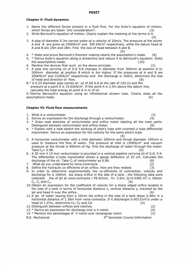
7/21/2019 Encribd Com Mech 4 Sem Course Info Feb June 07
http://slidepdf.com/reader/full/encribd-com-mech-4-sem-course-info-feb-june-07 45/66
PESIT
B.E. Mechanical 4th Semester Course Information
Chapter V: Fluid dynamics
1. Name the different forces present in a fluid flow. For the Euler’s equation of motion,which forces are taken into consideration?. (3)
2. Write Bernoulli’s equation of motion. Clearly explain the meaning of the terms in it.(4)
3. A pipe of diameter 0.3m carries water at a velocity of 20m/s. The pressure at the points
A and B are given as 350KN/m2 and 300 KN/m2 respectively, while the datum head atA and B are 25m and 28m. Find the loss of head between A and B.
(6)4. * State and prove Bernoulli’s theorem making clearly the assumption’s made. (8)5. * Derive Euler's equation along a streamline and reduce it to Bernoulli's equation. State
the assumptions made. (10)6. Mention the devices that work on the above principle. (2)7. A pipe line carrying oil of S.G 0.8 changes in diameter from 300mm at position A to
500mm diameter at position B which is 5m higher. If the pressures at A and B are200KN/m2 and 152KN/m2 respectively and the discharge is 150l/s, determine the lossof head and direction of flow. (8)
8.* A 0.25 diameter pipe carries an oil of SG 0.8 at the rate of 120 l/s and thepressure at a point A is 19.62kN/m3. If the point A is 3.5m above the datum line,calculate the total energy at point A in m of oil.
9.*Derive Bernoulli’s equation using an infinitesimal stream tube. Clearly state all theassumptions made. (6)
Chapter VI: Fluid flow measurements
1. What is a venturimeter. (2)2. Derive an expression for the discharge through a venturimeter. (4)3. * Draw neat sketches of venturimeter and orifice meter labeling all the main parts.
Distinguish between venturimeter and orifice meter. (8)4. * Explain with a neat sketch the working of pitot's tube with inverted U tube differential
manometer. Derive an expression for the velocity for the same pitot's tube.(6)
5. A horizontal venturimeter with a inlet diameter 200mm and throat diameter 100mm isused to measure the flow of water. The pressure at inlet is 150KN/m2 and vacuumpressure at the throat is 400mm of Hg. Find the discharge of water through the meter.Take Cd= 0.98. (6)
6. A 30 mm X 15 mm venturimeter is provided in a vertical pipeline carrying oil of S.G. 0.9.The differential U-tube manometer shows a gauge deflection of 25 cm. Calculate thedischarge of the oil. Take Cd of venturimeter as 0.98. (8)
7. What do you understand by Vena-Contracta. (2)8. Define the hydraulic co-efficients of an orifice. How are they related. (3)9. In order to determine experimentally the co-efficients of contraction, velocity and
discharge for a 100mm dia sharp orifice in the side of a tank , the following data were
collected. Dia of jet at vena-contracta =78.42mm, H= 3.6m, Q=0.0385 m3 / s. ObtainCc, Cv and Cd. (6)
10. Obtain an expression for the coefficient of velocity for a sharp edged orifice located inthe side of a tank in terms of horizontal distance x, vertical distance y, traveled by the jet and head H over the orifice . (6)
11. A jet of water issuing from a 25mm dia orifice in the side of a tank drops 0.48m in ahorizontal distance of 1.39m from vena-contracta. If it discharges 0.00131m3 /s under ahead of 1.07m, determine Cc, Cv and Cd. (4)
12. Distinguish between orifices and notches. (2)13. * Derive an expression for discharge over a V-notch. (4)14. * Mention the advantages of V-notch over rectangular notch. (3)

7/21/2019 Encribd Com Mech 4 Sem Course Info Feb June 07
http://slidepdf.com/reader/full/encribd-com-mech-4-sem-course-info-feb-june-07 46/66
PESIT
B.E. Mechanical 4th Semester Course Information
15. In an experiment on a 900 V-notch , the flow is collected in a vertical cylindrical tank0.9m dia. It is found that the depth of water in the tank increases by 0.65m in 16.8s,when the head over the notch is 0.2m. Determine the Cd of the notch. (4)
16. Find the depth and top width of a V-notch capable of discharging a maximum 0.7m3 /sand such that head the head shall be 75mm for a discharge of 5.6 litres
17. / s. It’s Cd is same as that of a similar (in material and sharpness of edges only) rightangled V-notch for which Q=1.407 H5/2. (6)
18. *Compare a Venturimeter and an orifice plate, based on the following points
(a) Cost and ease of manufacture(b) Accuracy(c) Energy loss(d) Sensitivity ( output manometer deflection per unit flow rate) (4)
19.* Derive the head vs. discharge relation equation for a V notch. State all theassumption made. (6)
20.*The inlet and throat diameters of a vertically mounted venturimeter are 300mmand 100mm respectively. The throat is below the inlet at a distance of 100mm.The mass density of the liquid is 900kg/m3. The pressure intensity at the inlet is140 kPa while at the throat is 80kPa. Calculate the flow rate. Assume that 2%of the differential head is lost between the inlet and the throat. (8)
Chapter-VII: Flow through pipes &
Chapter-VIII: Laminar & Viscous Flow
1. *Define Reynolds' Number. What is its physical significance? (4)2. For the flow of fluid through a circular pipe show that the friction factor f = 16/Re.
(6)3. Two reservoirs are connected by three pipes laid in parallel, their diameters being d, 2d
& 3d respectively and they are of the same length l. Assuming f to be the same for allpipes, determine the discharge through each of the larger pipes if the smallest pipe isdischarging 1m3 /s. (6)
4. * What are minor and major losses? Derive an expression to evaluate the loss of head
due to sudden contraction. (10)5. Write the expressions for the loss of head due to the following in pipes: Entrance to the
pipe, sudden contraction, sudden expansion, Exit from the pipe, Pipe fittings. (5)6. What is a compound pipe. Derive an expression for the equivalent size of a compound
pipe. (4)7. Two reservoirs are connected by a pipe 2250m long and 0.225m in diameter the
difference in water levels being 7.5m. Determine the flow through the pipe in litres /min if f = 0.03. Also find the % increase in the discharge if for the last 600m a secondpipe of the same diameter is laid alongside the first. (6)
8. Derive an expression for the loss of head due to friction for the laminar flow betweentwo parallel plates. (6)
9. A horizontal pipe 50mm diameter carrying glycerine has shear stress at the pipeboundary as 196.s N/m2. Determine the pressure gradient, mean velocity and
Reynolds' number. (6)10. * For turbulent flow through a pipe, derive Darcy’s equation for the head loss. (8)11. Two reservoirs are connected by a pipe 2250m long and 0.225m in diameter the
difference in water levels being 7.5m. Determine the discharge through the pipe if f =0.0075. (6)
12. Write short notes on Water hammer. (3)13. * Distinguish between Laminar and Turbulent flow. (4)14. * Explain the terms
(i) Critical Reynolds number(ii) Critical velocity(iii) Transition Zone (6)

7/21/2019 Encribd Com Mech 4 Sem Course Info Feb June 07
http://slidepdf.com/reader/full/encribd-com-mech-4-sem-course-info-feb-june-07 47/66
PESIT
B.E. Mechanical 4th Semester Course Information
15.* Derive the Darcy Weisbach equation for the loss of head due to friction in a pipe16.*What are hydraulic gradient and total energy lines.17.*Water is supplied to a town having a population of 1 lakh from a reservoir 6 km
away from the town and it is stipulated that half of the daily supply of 150 litresper head should be delivered in 8 hours. What should be the dia of the supplypipe. The loss of head due to friction in the pipe line is 12m. Take Chezy’s
constant as 45. (8)18.*In the Chezy equation V=C(RS)1/2, explain the physical meaning of the terms
C,R and S. (2)19.*Derive the expression for the energy loss due to a sudden expansion in a pipe
from area A1 to area A2(>A1), in terms of the inlet dynamic pressure ½ ρV12 Clearly state all the assumption made. (6)
20.*Starting from an appropriate control volume derive the expression for thevelocity distribution for steady, laminar, fully developed flow of an incompressible fluid
in a circular pipe.Further, show that the friction factor ƒ=2gDhf/LV2 is 64/Re for this flow. (10)
21.*For the system shown below qualitatively sketch the hydraulic and energy gradelines. The value is kept half open and the entry loss into the pipe is negligible
Chapter X: Introduction to compressible flow &Chapter IX: Flow past immersed bodies
1. Derive an expression for velocity of sound in a fluid in terms of bulk modulus.(4)
2. A projectile travels in air of pressure 0.065 N/m2 and temperature - 70C. If the Machangle is 300C, find the velocity of projectile. K = 1.4, R = 287 J / Kg K. (4)
3. Find the velocity of bullet in standard air if the Mach angle is 30o. Take R = 287.14 J/ kgo K and k = 1.4 for air. Assume temperature of air as 15o C.
4. Water at 15o C flows between two parallel plates at a distance of 1.6 mm apart.Determine the maximum velocity , the pressure loss per unit length, Shear stress at theplates, if the average velocity is 0.2 m/s. The viscosity of water at 15o C is given as0.01 poise. (8)
5. Define Mach No. What is its significance. (4)6. Derive an expression for the compressible flow of a fluid for (i) Isothermal process (ii)
Adiabatic process. (8)
smoothHo Rough
Valuekept half

7/21/2019 Encribd Com Mech 4 Sem Course Info Feb June 07
http://slidepdf.com/reader/full/encribd-com-mech-4-sem-course-info-feb-june-07 48/66
PESIT
B.E. Mechanical 4th Semester Course Information
7. An aeroplane is flying at an altitude of 15 Km where the temperature is -500. The speedof the plane corresponds to a Mach No.1.6. Assuming R = 1.4 andR = 2875/ kg-K, determine the speed of the aeroplane. (6)
8. * Explain the effect of area variation on one dimensional compressible fluid flow. (6)9. Define : Boundary layer thickness, Displacement thickness, Momentum thickness. (6)10. Derive an expression for velocity of propagation of elastic wave in an isothermal
medium. (8) 11. * A jet fighter flying at Mach number 2.0 is observed directly over head at a height of 10
km. How much distance it would cover before the sonic boom is heard on the ground? 12. * Explain (i) Lift (ii) Drag (iii) Wake region (iv) Boundary layer separation (8) 13. Define [a] Drag [b] Lift [c] Drag Co-efficient [d] Lift Co-efficient14. Define [a] Aero foil [b] Cord length [c] Angle of attack15. *Distinguish between friction drag and pressure drag. (5)16. *Sketch the nature of propagation of disturbance in compressible flow when Mach
number is more than one and hence define mach angle and mach cone. (6)17.*Experiment were conducted in a wild tunnel with a wind speed of 50 km/hr on a
flat plate of size 2m long and 1m wide. The specific weight of air is 11.282 N/m3 The plate is kept at such an angle that the coefficient of lift and drag are 0.75And 0.15 respectively. Determine:
(a) Lift force(b) Drag force(c) Resultant force(d) Power excited by air stream on the plate.(10)
18.*A Supersonic plane travels at 1.8 Mach at an altitude of 20Km above the groundHow far ahead the plane will be when one hears the sonic boom on theGround? (8)
19.*The velocity distribution in a boundary-layer is given by:u=U∝sin(π /2y/δ) 0≤y≤δ u=U∝ y≥δ
(a) Determine the displacement and momentum thickness if δ=cm andU∝=10m/s
(b) What would happen to the answer of part (a) above, if the shape of theVelocity profile remains the same and δ remains at 1cm but U∝ is doubled.
20.*An aircraft is flying at a uniform speed of 1Km/s at a height of 2 Km. Thedensity and pressure at that altitude are 0.6kg/m3 respectively.(a) How long after it flies directly overhead will the sonic boom be heard?
R for air is 287 J/kg/K and the ratio of specific heats, γ is 1.4. (6)(b) Calculate the pressure felt at the nose of the aircraft, assuming that, in the
Reference frames of the planes, the air is isentropically brought to rest at theNose. (4)
21.*Distinguish between the following:(a) form, drag and skin friction drag.(b) Lift force and drag force(c) The physical significance of displacement thickness and momentum thickness.(6)
* T h e s e q u e s t i o n s h a v e a p p e a r e d i n p a s t V TU q u e s t i o n p a p e r
KINEMATICS OF MACHINE–ME 44
Faculty: Sunith Babu. L

7/21/2019 Encribd Com Mech 4 Sem Course Info Feb June 07
http://slidepdf.com/reader/full/encribd-com-mech-4-sem-course-info-feb-june-07 49/66
PESIT
B.E. Mechanical 4th Semester Course Information
Class #Chapter Title /
Reference
LiteratureTopics to be covered
% Of Portions
Covered
1.
2.
Chapter #: 1.0
Introduction
T1: 1 - 19
R1: 3 – 14
Definition – Link or element, Paring of elementwith degrees of freedom, Grubler’s criterion(without derivation), Kinematic chain,Mechanism, Mobility of Mechanism, Inversion,
Machine
4 % 4 %
3.
4.
5
6.
Chapter #: 1.0
Kinematic chainand Inversion
T1: 20 - 30
R1: 15 - 21
Kinematic Chain and Inversion:
Kinematic chain with three lower pairs, Fourbar chain,
Single slider crank chain &
Double slider crank chain and
Their inversions
8 % 12 %
7.
8.
9.
10.
11.
12.
13.
Chapter #: 2.0
Mechanism
T1: 22 - 30
R1: 95 - 123
Mechanisms:
(I) Quick return mechanisms – Drag linkmechanism, Whitworth mechanism andCrank & slotted lever mechanism.
(II) Straight line motion mechanisms –Peacellier’s mechanism and Roberts’smechanism.
(III) Intermittent motion mechanisms – Genevamechanism and Ratchet & Pawl mechanism.
(IV) Toggle mechanism, Pantograph, Hooke’s joint and Ackerman steering mechanism
13 % 25 %
14.
15.
16.
17.
18.
19.
20.
21.
Chapter #: 3.0
Velocity and
AccelerationAnalysis of
Mechanisms
T1: 31 - 52
R1: 21 - 23
Velocity and Acceleration Analysis ofMechanisms
(Graphical Methods):
Velocity and Acceleration Analysis byvector polygons –
Relative velocity and acceleration ofparticles in a common link,
Relative velocity and accelerations ofcoincident particles on separate links,
Coriolis components of acceleration
15 % 40 %

7/21/2019 Encribd Com Mech 4 Sem Course Info Feb June 07
http://slidepdf.com/reader/full/encribd-com-mech-4-sem-course-info-feb-june-07 50/66
PESIT
B.E. Mechanical 4th Semester Course Information
22.
23.
24.
25.
26.
Chapter #: 4.0
VelocityAnalysis byInstantaneouscenter method
& Klein’s
constructionT1: 53 - 73
R1: 24 – 71
Definition,
Kennedy’s Theorem
Determination of velocity usinginstantaneous center method
Analysis of Velocity and Acceleration of singleslider crank mechanism by using Klein’s
construction
12%
52 %
27.
28.
29.
30.
Chapter #: 5.0
Velocity Analysisby Complex NoAnd Loop ClosureEquation
R2:
Velocity and Acceleration Analysis byComplex Numbers:
Analysis of
A) Single slider crank mechanism by
1) Loop closure equations
2) Complex numbers
B) Four Bar mechanism
1) Loop closure equations
2) Complex numbers
8%
60 %
31.
32.
33.
34.
35.
36.37.
38.
Chapter #: 6.0
Spur Gears
T1: 326 - 383
R1: 163 – 187
Law of gearing,
Involutometry,
Definitions, Characteristics of involute action,
Path of Contact, Arc of Contact, Contactratio, Interference in involute gears, Methods
of avoiding interference, Back lash,Comparison of involute and cycloidal teeth
15%
75 %
39.
40.
41.
42.
43.
44.
Chapter #: 7.0
Gear Trains
T1: 383 - 414
R1: 201 - 221
Simple gear trains,
Compound gear trains for large speedreduction,
Epicyclic gear trains,
Algebraic and tabular methods of findingvelocity ratio of epicyclic gear trains, Tooth
load and torqueCalculations in epicyclic gear trains.Differential mechanism of an automobile
12%
87 %

7/21/2019 Encribd Com Mech 4 Sem Course Info Feb June 07
http://slidepdf.com/reader/full/encribd-com-mech-4-sem-course-info-feb-june-07 51/66
PESIT
B.E. Mechanical 4th Semester Course Information
Learning Resources for the Subject
P r e s cr i b e d T e x t B o o k s :
Co d e T it l e A u t h o r ( s ) P u b l i sh e r / Ed i t i o n / Y e ar
T1. Theory of Machines – S. S. Rattan Tata Mc Graw Hill / Eighteen / 1998
T2. Mechanism and machine J. S. Rao New Age / Second / 2003
P r e s c r i b e d R e f e r e n c e B o o k s :
R1. Kinematics of Machines A.S Ravindran Sudha Publication / Fourth / 2004
Guidelines for Quick Study* [ACTUAL EXAM PATTERN MAY VARY]
Chapters 1 and 2 are theory type hence maintain descriptive answers in the exams with neat
sketches
Chapters 3 and 8 are to be solved in the Drawing Sheets hence practice problems in
Drawing Sheet only
Chapters 4 5 6 7 mainly contains problems of 15 to 20 marks while theory only 5 marks
45.
46.
47.
48.
49.
50.
51.
52.
Chapter #: 8.0
Cams
T1: 195 - 238R1: 124 - 162
Types of followers,Displacement,Velocity and Acceleration time curves forcam profiles,Disc cam with reciprocating followerhaving knife edge,Roller and flat faced follower, disc camwith oscillating roller follower, Followermotions including SHM, Uniform velocity,Uniform acceleration & retardation andcycloidal motion
13 % 100 %

7/21/2019 Encribd Com Mech 4 Sem Course Info Feb June 07
http://slidepdf.com/reader/full/encribd-com-mech-4-sem-course-info-feb-june-07 52/66
PESIT
B.E. Mechanical 4th Semester Course Information
QUESTION BANK
LINKAGES AND MECHANISMS:
1. Explain the following terms with examples(i) Element (ii) Link (iii) Kinematic pair (iv) Mechanism (v) Inversion(vi) Machine (vii) Mobility (viii) Degree of Freedom* (16)
2. Define a Kinematic pair. Explain the various types of Kinematic pairs. * (4)3. Distinguish between complete, incomplete and successful constraint of the relative
motion between the two links (4)4. Define the following (i) Lower pair (ii) Higher pair* (4)5. Define Kinematic chain and how does it differ from a mechanism * (4)6. Differentiate between (i) Machine and Mechanism (ii) Machine and structure*(8)7. Define mobility of a mechanism and write the Grubler’s mobility equation for planar
mechanism* (4)8. Write short notes on Kinematic chain with three lower pairs* (6)9. Sketch and explain the following* (12)
(i) Four Bar Chain and its inversions(ii) Single slider crank chain and its inversions
(iii) Double slider crank chain and its inversions10. Explain the working of an Ellipse Trammel and show how is it useful in drawing an
ellipse (10)11. Explain the construction of Oldham’s coupling and state for what purpose it is used*
(6)12. Describe the following quick return mechanism* (10)
(i) Drag Link(ii) Witworth
(iii) Crank and slotted lever mechanism13. What are straight-line motion mechanisms? How are they classified* (6)14. Describe Peacellier’s mechanism with a suitable sketch* (6)15. Describe Roberts approximate straight line motion mechanism with suitable sketches*
(4)16. What is a Pantograph and what are its uses? With neat sketches explain its working
principle * (6)
17. Describe toggle mechanism. What are its uses * (4)19. State and prove the condition that must satisfy by the steering mechanism of a car in
order that the wheel may have pure rolling motion when rounding a curve? (10)
19. Write short notes on Ackermann steering gear * (6)20. What is Hooke’s joint and what are its application* (4)21. What is a double Hooke’s joint? (4)
22. State the condition to be satisfied in double Hooke’s joint in order to provide auniform velocity ratio (8)
23. What is intermittent mechanism? Explain the following intermittent motion
Mechanism (i) Geneva (ii) Ratchet* (6)24. Two shafts are connected by a Hooke’s joint. The driving shaft rotates at a
uniform speed of 300 rpm and the angle between the shafts is 200. Find themaximum and minimum speed of the driven shaft and its max. Acceleration.c) Sketch & explain the working of a ratchet Mechanism
(10)25. A Hooke’s joint connects two shafts whose axes are inclined at 1500. The
driving shaft rotates at a uniform speed of 120 rpm. The driven shaft operatesagainst a study torque of 150 Nm and carries a flywheel whose mass is 45 kgand the radius of gyration is 140 mm. Find the maximum torque which will

7/21/2019 Encribd Com Mech 4 Sem Course Info Feb June 07
http://slidepdf.com/reader/full/encribd-com-mech-4-sem-course-info-feb-june-07 53/66
PESIT
B.E. Mechanical 4th Semester Course Information
be exerted by the driving shaft. At what value of ‘α ‘ will the total fluctuation ofspeed of the driven shaft be limited to 24 rpm (12)
26. Find the degree of freedom of the following mechanism shown in figure – 1 *(4)
27. In a with worth quick return mechanism as shown in figure – 2, OP = 240mm,OA = 150mm, AR = 165mm, RS = 430mm. If the crank OP rotates at anangular velocity of 2.5 rad/sec & has an angular acceleration of 20 rad/sec2,
determine the acceleration of the slider, the angular acceleration of the linkAR, RS. (10)
VELOCITY AND ACCELERATION IN MECHANISMS:
1. a) Write a brief note an instantaneous center of rotation. (4)b) A four bar chain ABCD as a fixed link AD = 1m. The driving rank AB = 0.3m. TheFollower link CD = 0.6 m and the connecting link BC = 1.2m. Find the velocity andacceleration of point ‘P’ midway between B and C When the angle BAD =135 0 and ABrotates at a speed of 300 rpm. (16)
2. Derive analytical expressions for velocity and acceleration of the piston in areciprocating engine mechanism.
b) The crank of a reciprocating engine is 60mm long and connecting rod is 240 mm long.The crank rotates at 400 rpm. Find the velocity and acceleration of both piston and theangular velocity and angular acceleration of the connecting rod when the crank is 300 from IDC by Klein’s construction method. (10)
3. In a slider crank mechanism, the crank is 50mm long and the connecting rod is150mm long. The crank is rotating at a speed of 10 rad/s and the crank is at 450 fromIDC. By kleins construction determine:i) Velocity of piston ii) Acceleration of the piston iii) Angular acceleration of theConnecting rod. (16)
4. A four bar chain mechanism ABCD is made up of 4 links pin jointed at ends. AD is fixedlink, which is 250 mm long. The links AB, BC & CD are 90mm, 180mm & 180mm longrespectively. The crank AB rotates at 100 rpm and an angular acceleration 100rad/sec2 at the instant when the crank AB makes an angle of 600 to the horizontal. Find theangular velocities and angular accelerations of links BC & CD.
(10)5. For the four bar mechanism shown in figure – 3, determine the acceleration of C and
angular acceleration of link 3 when crank 2, rotates at 20 radians per second. *(08)
6. Determine the velocity and acceleration of the piston by “Kleins Construction” for asteam engine for the following specification:Stroke of piston = 600mm, Ratio of length o connecting rod to crank length = 5, speedof the engine = 450rpm CW, position of the crank = 45 degree with IDC.
(10)7. Derive analytically the expression for the velocity and the acceleration of the piston in
a reciprocating engine mechanism. (10)8. The crank of a reciprocating engine is 90mm long and the connecting rod is 360mm
long. The crank rotates at 150rpm. Find the velocity and the acceleration of the piston
and angular velocity and angular acceleration of the connecting rod when the angle,which the crank makes with the IDC, is 300. (10)
9. A link ABC of a mechanism shown in figure – 4 is in motion. At the instant shown, ‘A’moves with 0.6 m/s in the direction shown and ‘B’ moves with a speed of 0.5 m/s/ findthe magnitude and direction of (i) Velocity of C and (ii) angular velocity of ABC. AB =BC = AC = 0.5cm x-x is parallel to AB, a reference line (08)
10. The crank of a slider crank mechanism rotates CW at a constant speed of 300 rpm.The crank is 150mm and the connecting rod is 600mm long. Determine (I) linearvelocity and acceleration of the mid point of the connecting rod (ii) Angular velocityand acceleration of the connecting rod, at a crank angle of 450 from IDC position.
(15)

7/21/2019 Encribd Com Mech 4 Sem Course Info Feb June 07
http://slidepdf.com/reader/full/encribd-com-mech-4-sem-course-info-feb-june-07 54/66
PESIT
B.E. Mechanical 4th Semester Course Information
11. An oscillatory cylinder mechanism is shown in the figure 5. The crank O2B rotates at300rpm (ccw). Determine the magnitude & direction ofI. Angular velocity of cylinder ii. Velocity of A3 a point on the system iii. Angularacceleration of the cylinder. Also state whether the magnitude of angular velocity. Isincreasing or decreasing at the instant A3 & A4 are coincident points of piston &cylinder respectively. O2B=150mm. O2O4=600mm. A3B=400mm. (15)
12. The crank of a slider crank mechanism is 480 mm long and rotates at 20 rad/sec in thecounter clockwise direction. It has a connecting rod of 160mm long, Determine the
following when the crank is at 60 degree from the inner dead center 1) Velocity ofslider 2) Angular velocity of connecting rod 3) The Position and velocity of a point P onthe connecting rod having at least absolute velocity. (15)
13. A pin jointed 4-bar mechanism ABCD is shown in figure - 6. LINK AB = 150mm, BC =180 mm CD = 180 mm, and the fixed Link AD = 300 mm. Link AB makes 60 degreewith Link AD and rotates uniformly at 100 rpm. Locate all the instantaneous centersand find the angular velocity of link BC and Linear velocity of link CD.(16)
14. Locate all the instantaneous centers for the toggle mechanism shown in figure –7(4)
15. Determine the velocity of point K in the mechanism shown in figure –8 (6)16. In the mechanism shown in figure – 9, crank rotates at 3000rpm. Find the acceleration
of the point c in magnitude, direction and sense. Find also the angular acceleration oflink 3. (10)
17. The crank 02A of the four bar mechanism shown in figure - 10 is rotating clockwise ata constant speed of 100 rad/sec. For the phase, shown in figure, determine I) theacceleration of the point c. II) the angular acceleration of link 3 and 4. (10)
18. A four bar chain ABCD has a fixed link AD = 1m. The driving rank AB = 0.3m. TheFollower link CD = 0.6 m and the connecting link BC = 1.2m. Find the velocity andacceleration of point ‘P’ midway between B and C When the angle BAD =135 0 and ABrotates at a speed of 300 rpm. (10)
19. In a slider crank mechanism, the crank is 50mm long and the connecting rod is150mm long. The crank is rotating at a speed of 10 rad/s and the crank is at 450 fromIDC. By kleins construction determine:
i) Velocity of piston ii) Acceleration of the piston iii) Angular acceleration ofthe Connecting rod * (15)
20. A four bar chain mechanism ABCD is made up of 4 links pin jointed at ends. AD is fixedlink, which is 250 mm long. The links AB, BC & CD are 90mm, 180mm & 180mm longrespectively. The crank AB rotates at 100 rpm and an angular acceleration 100rad/sec2 at the instant when the crank AB makes an angle of 600 to the horizontal. Find theangular velocities and angular accelerations of links BC & CD *
(20)21. The crank of an engine is 20cm long and connecting rod length to crank radius is 4.
Determine the acceleration of the piston when the crank has turned through 45 Degreefrom the inner dead center position and moving towards center at 240 rpm by thefollowing methods 1) complex algebra analysis 2) Klein’s construction and compare thevalues and get the error % figure – 11 * (20)
22. For the four bar mechanism shown in figure – 12 determine the acceleration of C andangular acceleration of link 3 when crank 2, rotates at 20 radians / sec* (10)
23. What is Coriolis component? Derive the expression for the same * (06)24. The crank of a reciprocating engine is 60mm long and connecting rod is 240mm long.
The crank rotates at 400rpm. Find the velocity and acceleration of the piston and theangular velocity and angular acceleration of the connecting rod, when the crank is 30degrees from inner dead center, by KLEIN’S construction. * (12)
25. What is instantaneous center? Locate all the instantaneous center for a single slidercrank mechanism and show how velocity of slider is determined? (08)
Velocity and acceleration analysis by complex method:

7/21/2019 Encribd Com Mech 4 Sem Course Info Feb June 07
http://slidepdf.com/reader/full/encribd-com-mech-4-sem-course-info-feb-june-07 55/66
PESIT
B.E. Mechanical 4th Semester Course Information
1. In an internal combustion engine mechanism, the crank radius is 100mm and thelength of the connecting rod is 450 mm. the crank is rotating at 10 rad/sec, in (CCW)direction. Determine the magnitude and direction of 1) Velocity of the piston 2) Theangular velocity of the connecting rod when crank is at 45 degree from the inner deadcenter by complex algebra method verify the same by Klein’s construction.
(15)2. In a 4 bar mechanism ABCD link, AB=300mm,BC=360mm,CD=360mm and the fixed
link AD=600mm. The angle of link AB with fixed is 60degree. The AB has an angular
velocity of 10rad/sec and angular acceleration of 30rad/sec2 both clock wise.Determine the angular velocity and angular acceleration of link BC and CD by RAVEN’Sapproach. * (20)
SPUR GEAR
1. What are toothed gears? State their uses* (4)2. What are the advantages and disadvantages of gear drives (4)3. How are gears classified* (4)4. State and prove “Law of gearing”* (6)5. What are the common curves used for tooth profile* (2)6. Discuss the merits and demerits of involute curve and cycloidal curve for the
profile of gear tooth. (6)7. What are the general Characteristics of spur gearing* (4)8. Draw a neat sketch of spur gear and explain the various terms (6)9. Define the following (i) Pitch circle diameter (ii) Circular Pitch (iii) Module
(iv) Addendum (v) Dedendum (vi) Pressure angle*10. Define the following (i) Path of Contact (ii) Arc of Contact (iii) Contact Ratio*
(12)11. Derive the formula for the length of arc of contact for two meshing spur Gears of
involute profile* (6)12. Explain the phenomenon of interference. State the condition for no Interference
(4)13. Describe the various methods of avoiding interference (4)
14. Derive an expression for minimum number of teeth necessary for a pinion to avoidinterference. (10)
15. Derive an expression for the length of path of contact for a pinion on rack (6)16. What is Involutometry? Derive an expression for the tooth thickness at any point on
the involute, if the tooth thickness at some other point is known (10)17. What is Backlash? Derive an expression for backlash if the center distance is pulled
apart at a distance Δc. (10)18. Two equal spur gears of 48 teeth mesh together with pitch radii of 100 mm, and the
addendum is 4.25 mm. If the pressure angle is 200, calculate the length of action andcontact ratio. Sketch the different types of gear trains and explain briefly (20)
19. A pair of gears having 40 and 20 teeth are rotating in mesh the speed of smaller being1800rpm. Determine the velocity of sliding between the gear teeth faces at the point ofengagement, at the pitch point, at the point of disengagement if the smaller gear is thedriver. Assume the gear teeth 200 involute form, addendum length is 5mm and themodule is 5mm (20)
20. The number of teeth on each of two equal spur gears is mesh each other are 40. Theteeth have 200 involute pressure angle and module is 5mm. If the arc of contact is1.75 times the circular pitch. Find the addendum (10)
21. The following are the particulars of a single reduction spur gear the gear ratio is 10: 1and the center distance is 275mm. The pinion transmits 375 KW at 1800 rpm. Theteeth's are of involute form with standard addendum of 1 module and pressure angle is22.50. Normal tooth pressure is not to exceed 9810N/cm width. Find (I) the nearest

7/21/2019 Encribd Com Mech 4 Sem Course Info Feb June 07
http://slidepdf.com/reader/full/encribd-com-mech-4-sem-course-info-feb-june-07 56/66
PESIT
B.E. Mechanical 4th Semester Course Information
standard diameter pitch if no interference is to occur (ii) the number of teeth in eachwheel (iii) the width of pinion* (20)
22. A spur Pinion 100 mm in diameter has a torque of 200Nm applied to it. The spur gearin mesh with it is 250 mm in dia. the pressure angle is 20 degree. Determine thetangential force FT and the separating force FR. Show the forces action on the wheelsseparately. * (5)
23. Two Gear wheels mesh externally and are to give a velocity ratio of 3. The teeth are ofinvolute form of module 6mm, and the standard addendum is one module. If the
pressure angle is 180 and the pinion rotates at 90 rpm. Find i) The minimum numberof teeth on each wheel to avoid interference. The length of path of contact iii) Themaximum velocity of sliding iv) number of pairs of teeth in contact* (16)
24. The following data refers to two mating involute gears of 200 pressure angle:Number of teeth on pinion – 20Module – 12mmIf the center distance between the gears is increased by 2mm, find the backlashbetween the gears.
(15)25. Two spur gears wheels have 24 and 30 teeth and a standard addendum of 1 module.
The pressure angle is 200. Calculate the path of contact and arc of contact. Derive theexpression used. * (15)
26. The following data refers to two mating involute gears of 200 pressure angle. Numberof teeth on the pinion is 20, gear ratio is 2, speed of the pinion is 250rpm, module12mm. If the addendum on each wheel is such that the path of approach and the pathof recess on each side are half of the maximum permissible length. Find the maximumvelocity of sliding during approach and the recess and the length of arc of contact. *
(14)27. A pair of gear has 16 teeth and 18 teeth, a module 12.5 mm an addendum 12.5mm
and a pressure angle 14.5 degrees. Prove that gears have interference. Determine theminimum number of teeth and the velocity ratio to avoid interference. * (08)
GEAR TRAINS
1. What do you understand by gear trains (2)
2. Explain Train Value? How is it related to velocity ratio? * (4)3. Name different types of Gear Trains and give examples (4)4. Explain Simple, Compounded & Reverted gear trains * (6)5. Explain Epicyclic gear trains (2)6. Explain Bevel gear differential* (4)7. Explain Spur gear differential (4)8. Obtain the expression for the length of path of contact for two involute profile gears in
mesh (10)9. In an epicyclic gear train of ‘ SUN & PLANET’ type the sun wheel has 15 teeth and is
fixed to the motor shaft rotating at 1500 rpm. The planet P; three in number has 45teeth's gears with fixed annulus ‘A’ and rotates on a spindle cared by an arm which isfixed to the output shaft. The planet ‘P’ also gears with the sun wheel ‘S’ Find thespeed of the output shaft, if the motor transmits 2Kw. Find the torque required to fitthe annulus. (20)
10. An internal wheel B with 80teeth is keyed to shaft F. A fixed internal wheel C with 82teeth is concentric with B. A compound wheel DE gears with the two internal wheels: Dhas 28 teeth and gears with C while E gears with B. The compound wheel revolvesfreely on a pin, which projects from a disc keyed to a shaft A co-axial with F. If thewheels have the same pitch and the shaft A makes 800rpm, What is the speed of theshaft F. Sketch the arrangement. (15)
11. In a reverted epicyclic gear train the arm A carries two wheels B & C and a compoundwheel DE. The wheel C gears with wheel D. The number of teeth on wheel B, C&D are

7/21/2019 Encribd Com Mech 4 Sem Course Info Feb June 07
http://slidepdf.com/reader/full/encribd-com-mech-4-sem-course-info-feb-june-07 57/66
PESIT
B.E. Mechanical 4th Semester Course Information
75, 30 & 90 respectively. Find the speed and directions of the wheel C when wheel B isfixed and the arm A makes 100rpm clockwise (15)
12. In a planetary gear system of sun and planet type, the sun wheel A has 20 teeth andis fixed to the frame. The arms C with Planet gear wheel B with 40 teeth revolve aboutthe gear wheel A. When the arm rotates at 30rpm, determine the speed planet gear B
(10)13. Figure – 13 shows an epicyclic gear train Wheel E is fixed and Wheel C and D are
integrally cast and mounted on the same pin. If arm A makes 1 revolution/ sec (CCW),
determine the speed and direction of the wheels B and F. (15)14. In the gear train shown in figure – 14. The wheel C is fixed, the gear B is connected to
the input shaft, & the gear F is connected to the output shaft. The arm A, carrying thecompound wheels D & E, turns freely on the output shaft. If the input speed is100rpm(ccw) when see from right. Determine the speed of output shaft. The No ofteeth on each gear is indicated in the fig. Find the output torque & the holding torqueto keep the wheel C fixed if the input power is 7.5kW* (20)
15. In the epicyclic gear train shown in figure - 15 A gear C, has teeth cut both internally& externally. The gear C is free to rotate on an arm driven by shaft S1 & meshesexternally with the casing D & internally with pinion B.The gears have the following No.Of teeth TB=24, TC=32 & 40, TD=48. Determine the vel. Ratio between S1 & S2 whenD is fixed S1 & D when D is fixed
(15)16. In an epicyclic gear train shown in figure - 16 the internal wheels A, Fand the
compound wheels C, D rotate about the axis O. The wheels B and E rotate on a pinfixed to the arm L. The wheels have same pitch and the number of teeth on B and Eare 18, C = 28, D = 26. If the arm L makes 150rpm clockwise, find the speed of Fwhen I) Wheel A is fixed and II) Wheel A makes 15rpm (CCW) by tabular columnmethod. (10)
17. In an epicycle gear train, the internal wheel A and B the compound wheel C and Drotate independently about axis O. The wheel E and F rotate on pins fixed to the armG. E gears with A and C and F gears with B and D. All wheels have the same moduleand the number of teeth are Tc = 28, Td = 26, Tf = 18,
i) Sketch the arrangementii) Find the number of teeth on A and B
iii) If the arm G makes 100rpm clock wise and A is fixed, find B speediv) If the arm G makes 100 rpm CW and wheel A makes 10rpm, CCW find
speed of B
CAMS
1. Give the classification of cams and follower* (4)2. Discuss the types of follower displacement diagrams* (4)3. Write short notes on cams and follower * (4)4. Why a roller follower is preferred to that of Knife edge follower (4)5. Explain w.r.t. Cams a) Base Circle b) Pitch circle 3) Pressure angle (6)6. What are the different types of follower motions (4)7. Derive an expression for velocity acceleration & displacement when the circular arc
cam is operating on an flat faced follower(i) When the contact is on the circular flank
(ii) When the contact is on circular nose (10)8. Derive an expression for velocity acceleration & displacement when the tangent cam is
operating on an radial translating roller follower When the contact is on straight flankWhen the contact is on circular nose (4)
9. Draw the outline of a cam which will transmit motion to a roller follower in thefollowing manner I) the follower to move outwards through a distance of 65 mmduring 180 degree of cam rotation. ii) Follower to return to its initial position during150 degree of cam rotation. iii) Follower to dwell for the remaining 30 degree of cam

7/21/2019 Encribd Com Mech 4 Sem Course Info Feb June 07
http://slidepdf.com/reader/full/encribd-com-mech-4-sem-course-info-feb-june-07 58/66
PESIT
B.E. Mechanical 4th Semester Course Information
rotation. The minimum radius of the cam is 30 mm & the displacement of the followeris to take place with cycloidal motion both during outward & return strokes. The rollerdiameter is 10mm & the follower axis is offset by 10mm from the axis of the shaft. *(8)
10. Draw the profile of the cam to give the following motion to the follower—Follower tomove through 30mm. During 180oof cam rotation with cycloidal motion. Follower toreturn with cycloidal motion during 180o of cam rotation. Base circle dia. of the cam is30mm and the roller dia of the follower is 10mm.the axis of the roller is offset by 8mm
to the right. Determine the maximum velocity and acceleration of the follower duringthe outstroke, when cam rotates at 2000rpm. * (8)
11. A disc cam is required to lift a flat-faced follower with U.A.R.M motion through 30 mmin 1/3 rd revolution. Keep it fully raised through 1/6th revolution & to lower it withS.H.M. in 1/3rd revolution and to dwell during rest of the revolution .The minimumradius of the cam is 25 mm. Draw the cam profile & also determine the maximumvelocity & acceleration of the follower during and return strokes if the cam rotates at200 rpm clockwise. * (20)
12. Draw the cam profile for the cam with reciprocating follower .The axis of the followerpasses through the axis of the cam. Details of the cam & the follower motion are thefollowing: Roller dia = 10mm, minimum radius of the cam = 22 mm, Total lift = 25mm .The cam has to lift the follower with SHM during 180 degree of cam rotation, thenallows the follower to drop suddenly halfway & further return the follower with UARMduring the remaining 180 degree cam rotation. Calculate the maximum velocity &acceleration of the follower during outstroke
(20)13. A push rod operated by a cam is to rise and fall with SHM along an inclined path. The
least radius of the cam is 30 mm and push rod is fitted at its lower end with a roller 15mm diameter. When in its lowest position, the roller center is above the cam axis. Themax. Displacement of the follower is 40 mm in a direction 30 degree to the right of thevertical .The cam rotates at 100 rpm in a clockwise direction .The time of lift is 0.15sec & the time of fall is 0.10 sec with a period of rest of 0.05 sec at the upper position,draw the graphical cam profile. (20)
14. A knife edged follower for the fuel valve of a four stroke diesel engine has its centerline coincident with the vertical center line of the cam .It rises 25 mm with SHM during
600
of cam rotation, then dwells for 30 degree of cam rotation and finally descendswith UARM during 90 degree of cam rotation, the deceleration period being 1/2 theacceleration period .The least radius of the cam is 30 mm. Draw the profile of the camto full size. (10)
15. It is required to set out the profile of a cam for the following data.i) Follower to move outward through an angular displacement of 20 degree during 900 of cam rotation ii) Follower to dwell for 45 degree of cam rotation .iii) Follower to dwellfor the remaining period of the revolution of the cam .iv) Follower to return to its initialposition of zero displacement in 5 degree of cam rotation. * (20)
16. The distance between the pivot center and the roller follower center is 70mm. Rollerdia is 10mm, minimum radius of cam is 30mm .The location of the pivot is 70mm tothe left and 50mm above the axis of the cam. The motion of the follower is to takeplace with SHM during outstroke and with UARM during return stroke, the acceleration
during outstroke of the follower, if the cam speed is 1200rpm. * (15)17. A cam rotating clockwise at uniform speed of 300rpm operates a reciprocating follower
through a roller 10mm dia the follower motion is defined: (I) Follower to moveoutwards during 1200 of the cam rotation with equal uniform acceleration and de-acceleration. (ii) Follower to dwell in the lifted position for the next 300 of camrotation. (iii) Follower to return to its starting position during 1200 of cam rotation withSHM. (iv) Follower to dwell for the rest of cam rotation* (15)
18. Draw the full size cam profile for a cam with roller of 25mm dia attached to thefollower to give a lift of 35mm. Axis of the follower is offset to right of cam axis by18mm. Ascend of the follower takes place with SHM in 0.05sec follower by a period ofrest of 0.0125sec. The follower then descends with UARM during 0.125sec and the

7/21/2019 Encribd Com Mech 4 Sem Course Info Feb June 07
http://slidepdf.com/reader/full/encribd-com-mech-4-sem-course-info-feb-june-07 59/66
PESIT
B.E. Mechanical 4th Semester Course Information
remaining period rest at the minimum lifted position. The acceleration being 3/5 timesretardation. The cam rotates in CCW direction at a constant speed 240rpm and thebase radius is 50mm*(20)
19. A translating roller follower has lift of 4cm. The follower has a uniform acceleration andretardation motion for both rise and return phases. How ever during the riseacceleration is twice the retardation. And during return the duration of acceleration istwice the duration of retardation. The angle of rotation of cam during rise and return is1500 each. The duration of the dwell before and after the rise is 30 0. Draw the
displacement diagram of the follower. Do not draw the cam profile* (20)20. A cam rotates at a uniform speed of 300 rpm clock wise and gives an oscillating
follower 75mm long, an angular displacement of 30 degree in each stroke. Thefollower is fitted with a roller of 20mm diameter, which makes contact with the cam.The outward and inward displacement of the follower each occupying 120 degree camrotation and there is no dwell in the lifted position. The follower moves through out bySHM. The axis of fulcrum is 80mm from the axis of cam and the least distance of rolleraxis from cam axis is 40mm* (20)
21. A roller follower is offset to the left by 1.2cm.the base circle radius of the cam is3cm.the desired displacement of the follower Y for any cam rotation θ is listed in thetable given below. Layout the cam profile if the radius of roller follower is 1cm. Thecam rotates in clockwise direction. * (20)
Cam rotationθo
0 30 60 90 120 150 180 210
240 270 300 330
Follower (cm)Y displacement
0 0.25 0.92 1.87 2.83 3.50 3.75 3.5 2.83 1.87 0.92 0.25
22. Draw the full size cam profile for a cam with roller of 25mm diameter attached to thefollower to give a lift of 35mm. Axis of the follower is offset to right of cam axis is18mm. Ascent of the follower takes place with SHM 0.05sec followed by a period of set0.125sec. The Follower then descends with UARM during 0.125sec and the remainingperiod as rest in the minimum lifted position, the acceleration being ¾ timesretardation. The cam rotates in CCW direction at a constant speed of 240rpm and thebase radius is 50mm (20)
* Questions appeared in VTU examinations
METROLOGY & MEASUREMENTS – IP42 B
Faculty: S.V.Satish/ Mukesh Patil
Class # Chapter title /ReferenceLiterature
Portions to be covered %Covered
PART-A1 – 4 Standards of
Measurement:R1:34-40R2:311
1.1-Definition and objectives of metrology1.2-Standards of length - international prototype meter1.3-Imperial standard yard, wave length standard1.4-Subdivision of standards1.5-Line and end standards1.6-Comparison1.7-Transfer from line standard to end standard1.8-Calibration of end bars (numericals)1.9-Slip gauges1.10-Wringing phenomena1.11-Indian Standards (M-87, M-112)
8

7/21/2019 Encribd Com Mech 4 Sem Course Info Feb June 07
http://slidepdf.com/reader/full/encribd-com-mech-4-sem-course-info-feb-june-07 60/66
PESIT
B.E. Mechanical 4th Semester Course Information
1.12-Numerical problems on building of slip gauges
5 – 13 System of Limits,Fits, Tolerancesand gauging:R1: 73-110R2: 312-446
2.1-Definition of tolerance2.2-Specification in assembly2.3-Principle of interchangeability and selective assembly2.4-Limits of size2.5-Indian standards2.6-Concept of limits of size and tolerances2.7-Compound tolerances
2.8-Accumulation of tolerances2.9-Definition of fits2.10-Types of fits and their designation (IS 919-1963)2.11-Geometrical tolerance2.12-Positional tolerances2.13-Hole basis system and shaft basis system2.14-Classification of gauges2.15-Brief concept of design of gauges (Taylor’s principle)2.16-Wear allowance on gauges2.17-Types of gauges -Plain plug gauge, ring gauge, snapgauge, limit gauge2.18-Gauge materials
26
14 – 18 Comparators:R1 : 63-70R2: 447 - 519
3.1-Introduction to comparator3.2-Characteristics and classification of comparators3.3-Mechanical comparators
- Johnson mikrokator- Sigma comparators- Dial indicator
3.4-optical comparators-principles3.5-Zeiss ultra optimeter3.6-Electric and electronic comparators-principles3.7-LVDT3.8-pneumatic comparators3.9-Back pressure gauges3.10-Solex comparators
38
19 – 22 AngularmeasurementsandInterferometerR1 : 111 – 127R2 : 654 - 724
4.1-Bevel protractor4.2-Sine principle, Sine bar, Sine center, Angle gauges(numericals on building of angles)4.3-Clinometers4.4-Principle of Interferometry4.5-Autocollimeter4.6-Optical flats
44
23 – 26 Screw thread andGearmeasurementR1 : 174- 190R2 : 879 -1008
5.1-Terminology of screw threads5.2-Measurement of major diameter5.3-Minor diameter5.4-Pitch5.5-Angle and effective diameter of screw threads by 2-wire & 3-wire methods5.6-Best size wire5.7-Tool makers microscope5.8-Gear terminology5.9-Use of gear tooth Vernier caliper5.10-Use of gear tooth micrometer
52
PART-B26 – 31 Measurements &
MeasurementsystemsR1: 268-270
6.1-Definition and Significance of measurement6.2-Generalised measurement system6.3-Definition and concept of accuracy6.4-Precision, sensitivity, calibration, threshold,
62

7/21/2019 Encribd Com Mech 4 Sem Course Info Feb June 07
http://slidepdf.com/reader/full/encribd-com-mech-4-sem-course-info-feb-june-07 61/66
PESIT
B.E. Mechanical 4th Semester Course Information
-hysteresis, repeatability linearity, loading effect-System response, time delay-Errors in measurements, classification of errors
32 – 35 TransducersR1:271-314
7.1-Transfer efficiency7.2-Primary and secondary transducers7.3-Mechanical, Electrical, electronic transducer7.4-Advantages of each type transducers
70
36 – 38 Intermediate
modifying devicesR1: 315-326
8.1-Mechanical systems
8.2-Inherent problems8.3-Electrical intermediate modifying devices8.4-Input circuitry8.5-Ballast circuit8.6-Electronic amplifiers and telemetry
76
39 – 40 TerminatingDevices
9.1-Mechanical9.2-Cathode Ray Oscilloscope9.3-Oscillographs9.4-X-Y Plotters
80
41 – 43 Measurement offorce & torqueR1:368-379
10.1-Principle10.2-Analytical balance10.3-Platform balance
10.4-Proving ring10.5-Torque measurement:- Prony brake dynamometer- Hydraulic dynamometer
86
44 – 46 PressuremeasurementsR1:380-418
11.1-Principle11.2-Use of elastic members11.3-Bridgeman gauge11.4-Mcleod gauge11.5-Pirani gauge
92
47 – 49 TemperaturemeasurementR1:419-455
12.1-Resistance thermometers12.2-Thermocouple12.3-Laws of thermocouple12.4-Materials used for construction of thermocouple
12.5-pyrometer12.6-Optical pyrometer
98
50– 52 StrainmeasurementR1:275-312
13.1-Strain gauge13.2-Preparation and mounting of strain gauges13.3-Gauge factor13.4-Methods of strain measurement
100
Text Books:1. Mechanical Measurements - Beckwith ,Marangoni & Lienhard2. Engineering Metrology- I.C.Gupta
Reference Books:
1.
Mechanical Measurements – Holeman2. Mechanical Measurements – Sirohi & Radhakrishna3. Mechanical measurements-Doblin4. Metrology for engineers-J.F.Galyer & C.R.Shotbolt5. Industrial Instrumentation-Alsutko & Jerry.D.Faulk6. Engineering Metrology - R.K.Jain
Scheme of examination:

7/21/2019 Encribd Com Mech 4 Sem Course Info Feb June 07
http://slidepdf.com/reader/full/encribd-com-mech-4-sem-course-info-feb-june-07 62/66
PESIT
B.E. Mechanical 4th Semester Course Information
Four questions to be set from Metrology – Part AFour questions to be set from Measurements – Part BAnswer any five questions taking at least TWO questions from each part.
QUESTION BANK
PART-A
Chapter 1: Standards of Measurement
1. Define Metrology. Explain various standards of length.2. What do you understand by line and end standards? Discuss their relative
characteristics.*3. Enumerate the advantages of using wavelength standard as a basic unit to define
primary standards.*4. Explain the NPL method of deriving end standards from line standards.*5. What are Airy points? How do they differ from the points of minimum deflection.*
Chapter 2: System of Limits, Fits, Tolerances and Gauging
1. What is the difference between unilateral and bilateral tolerances? Why unilateraltolerance is preferred over bilateral tolerance?*
2. Explain what is meant by:i) Interchangeable partii) Universal interchangeabilityiii) Local interchangeability*
3. Determine the type of fit, after deciding the fundamental deviations and tolerances inthe following:
Fit Ø 70H9e7, Diameter step (50-80)Fundamental deviation for e shaft = -11D0.41 IT7=16i, IT9=40i
i=0.453
√D+0.001D*4. Calculate the dimensions of plug and ring gauges to control the production of 50mm
shaft and hole pair of H7d8.The following assumptions may be made.50mm falls in thediameter step of 30-50mm.Upper deviation for “d”shaft is –16D0.44.IT7=16i,IT8=25i, i=0.453√D+0.001D *
5. Explain different types of fits.6. Write neat sketches and explain 'go' and 'Nogo' gauges.7. Briefly explain interchangeability.8. Briefly explain selective assembly.9. Explain Taylor's principle for 'go' and 'Nogo' gauges.10. Differentiate between:
i) Tolerance and allowanceii) Hole basis system and shaft basis system *
11. Explain Taylor’s principle for the design of limit gauges. *12. Illustrate with examples:
i) Geometrical toleranceii) Dimensional toleranceiii) Positional tolerance
13. A shaft-hole pair is designated as H7d8.The standard tolerance is given byi=0.453√D+0.001D,where D=Diameter(mm)falling in the step 18-30mm.Thefundamental deviation for fit d is given by –16D0.44 Take wear allowance as 10% of thegauge tolerance. Determine the shaft and hole dimensions, their tolerances, clearance,interference and the class of fit. Sketch the fit and mark the dimensions clearly. *

7/21/2019 Encribd Com Mech 4 Sem Course Info Feb June 07
http://slidepdf.com/reader/full/encribd-com-mech-4-sem-course-info-feb-june-07 63/66
PESIT
B.E. Mechanical 4th Semester Course Information
Chapter 3: Comparators1. What are the required characteristics of comparators?*2. What are the advantages of electrical comparator over mechanical comparator?3. Explain the working of Sigma comparator with neat sketches.4. Explain the working of Jhonson's Microkrater with neat sketches.*5. Explain the working of Brook level comparator with neat sketches.6. Explain the working of Optical comparator with neat sketches.7. What is the difference between a comparator and a measuring instrument? *
Chapter 4: Angular Measurements
1. Explain why it is preferred not to use a sine bar for generating angles larger than 45oifhigh accuracy is desired.*
2. Explain how sine bars are used for measurement of angle. Show the arrangement ofgauges.
i)57o 34’9” ii)12o20’36” *3. With a neat sketch explain Bevel protractor.4. With a neat sketch explain Universal Protactor.5. Give the significance of Clinometer in angular measurement.6. Write neat sketch and explain the principle of working of Auto Collimeter.7. How is setup of angular gauges different from simple gauges? Explain with an example.8. Sketch and label the parts of a Vernier bevel protractor. *9. Distinguish between:
i) Sine bar and sine centerii) Angle gauges and slip gauges. *
10. Select the sizes of angle gauges required to build the following angles:i)31deg29min24secii)102deg8min42sec *
Chapter 5: Screw thread and Gear measurement
1. Give the procedure to measure major and pitch diameter using 3 wire method.
2. Distinguish between 2 wire and 3 wire methods of measuring and suggest the bestone.
3. What are the two corrections applied in the measurement of effective diameter by themethod of wires?*
4. Explain the working principle of Tool Makers Microscope.5. Describe screw thread terminology with sketch.6. Compare profile projector with tool makers microscope.7. What are the various types of pitch errors on threads and explain the reasons for the
same. *8. How do you find effective diameter of a screw thread using two-wire method. *9. How do you measure the following in case of a spur gear:
i) Runoutii) Tooth thickness
iii) Backlash *10. Explain the terminology of a simple Spur gear11. Describe a Gear Tooth Vernier caliper and show how this is used for checking gear. *12. Explain how Gear Tooth Vernier is used for gear measurement.
PART-B
Chapter 6: Measurements and measurement systems

7/21/2019 Encribd Com Mech 4 Sem Course Info Feb June 07
http://slidepdf.com/reader/full/encribd-com-mech-4-sem-course-info-feb-june-07 64/66
PESIT
B.E. Mechanical 4th Semester Course Information
1. What do you mean by static calibration? Sketch the calibration curve of an instrumentand explain how it is obtained?*
2. Explain the following:i) Zero drift and sensitivity driftii) Threshold, Resolution and Hysteresis*
3. What are the sources of errors in instruments? Explain*4. What is a measurement?5. Draw a block diagram of generalized measurement systems and explain the salient
features of each stage.6. With the help of examples, distinguish between the two fundamental methods of
measurement.7. State the three basic elements of a measuring system and give an example to each of
the basic elements.8. Draw the displacement time characteristics for damped motion and explain the
importance of damping.9. Draw a block diagram of a generalized measurement system and explain the salient
feature of each stage.10. Distinguish between:
i) Digital and Analog measurementii) Direct reading and null balancing *
11. For Oscillating systems, show that, a more sensitive instrument oscillates moreslowly than a less sensitive instrument.
12. Draw a neat block diagram of measurement system employed for measuringacceleration.
13. Explain the following: i) Accuracy ii) Sensitivity iii) Precision14. Explain briefly the different types of errors encountered during measurement.15. Write a brief note an treatment of multisampling data.16. What are the requirements and objectives of measurement?17. State and explain the various forms of input to the instrument.18. Explain with an example the various stages of a generalized measurement system. *19. Explain with sketches:
i) Hysteresisii) Threshold
iii) Repeatabilityiv) Sensitivity drift *
Chapter 7: Transducers
1. Define the word Transducer. What do you understand by active and passivetransducers? Give examples.*
2. Explain the following with neat sketches:i)Mutual inductance transducerii)Piezo electric transducer*
3. Explain any one type of elastic transducer with a neat sketch.*4. Mention the advantages of electrical primary detector transducer elements over other
types.5. Describe with a neat sketch the ionization transducer.
6. Define transfer efficiency.7. Mention six mechanical elements used as detector transducers and indicate the
operations, which they perform.8. Discuss the relative merits and demerits of mechanical and electrical transducers.9. What are the parameters on which capacitive transducers are developed. Explain the
working of a pickup used for determining the level of liquid nitrogen with a neat sketch.10. With a neat sketch explain the working of a transducer using electro kinetic
phenomenon and indicate its applications.11. Explain the principle of working of a linear variable differential transducer with a neat
sketch and illustrate its characteristics.

7/21/2019 Encribd Com Mech 4 Sem Course Info Feb June 07
http://slidepdf.com/reader/full/encribd-com-mech-4-sem-course-info-feb-june-07 65/66
PESIT
B.E. Mechanical 4th Semester Course Information
12. What are the relative merits and demerits of electrical transducers over mechanicaltransducers?
13. Explain the principle of working of a piezoelectric transducer with a neat sketch.14. What are primary and secondary transducers? Explain with examples.15. Explain the working of a electronic transducer with a neat sketch.16. What are active and passive transducers, give examples.17. Explain the principle of variable resistance transducers with a neat sketch.18. What are photoelectric transducers? Explain any one type with a neat sketch.
19. Explain the principle of variable inductance transducer with a neat sketch.20. Distinguish between active and passive transducers. *21. Explain with neat sketches the following:
i) Piezo electric transducerii) Ionization transducer *
11. Discuss briefly with sketches two types of elastic pressure transducers. *
Chapter 8: Intermediate modifying devices
1. Explain in brief inherent problems encountered in mechanical systems as intermediatemodifying devices.
2. Give the advantages of electrical modifying devices compared to mechanical ones.3. Explain with a neat sketch ballast circuit.4. Write short notes on:
i) Electronic amplifiersii) Telemetry
Chapter 9:Terminating Devices
1. With a neat sketch explain the construction and working of Cathode ray oscilloscope.2. Write short notes on:
i) Oscillographsii) X-Y Plotters
Chapter 10: Measurement of force and torque
1. With the help of a neat sketch explain the working of a prony brake dynamometer.*2. Explain with a neat sketch the analytical balance. *
3. Write a note on hydraulic dynamometer4. How is electric dynamometer different from mechanical ones?5. Explain with a neat sketch, the method of torque measurement of rotating shafts using
strain gauges. *
Chapter 11:Pressure measurements
1. Explain with sketches the proper orientation of strain gauges for measurement of (i)Bending strain (ii) Torsional strain (iii) Axial strain.
2. How do you define high pressure range and low pressure range.3. Explain with neat sketch the working of any one device used for measurement for high
pressure.4. Explain with a neat sketch the working and application of a Bridgeman gauge.*5. With neat sketches explain Mcleod and Pirani gauges.
6. With neat sketches, explain the working principle of :i) Mcleod gaugeii) Knuolsm gauge *
Chapter 12: Temperature measurement
1. What are pyrometers? Explain any one.2. How resistance thermometer is used to measure temperature with advantages.3. Explain the thermocouple way of measuring temperature.*4. Differentiate between radiation and pressure thermometer.5. With a neat sketch explain bi-metal strip thermometer. *6. With a neat sketch explain resistance thermometer. *

7/21/2019 Encribd Com Mech 4 Sem Course Info Feb June 07
http://slidepdf.com/reader/full/encribd-com-mech-4-sem-course-info-feb-june-07 66/66