energy management working group brad schoening - … · energy management working group brad...
TRANSCRIPT

Energy Management Working Group Brad Schoening Internet Draft Independent Consultant Intended status: Informational Mouli Chandramouli Expires: October 19, 2013 Cisco Systems Inc. Bruce Nordman Lawrence Berkeley National Laboratory April 19, 2013
Energy Management (EMAN) Applicability Statement draft-ietf-eman-applicability-statement-03
Abstract
The objective of Energy Management (EMAN) is to provide an energy management framework for networked devices. This document presents the applicability of the EMAN framework to a variety of scenarios. This document lists use cases and target devices that can potentially implement the EMAN framework and associated SNMP MIB modules. These use cases are useful for identifying requirements for the framework and MIBs. Further, we describe the relationship of the EMAN framework to relevant other energy monitoring standards and architectures.
Status of this Memo
This Internet-Draft is submitted to IETF in full conformance with the provisions of BCP 78 and BCP 79.
Internet-Drafts are working documents of the Internet Engineering Task Force (IETF), its areas, and its working groups. Note that other groups may also distribute working documents as Internet-Drafts.
Internet-Drafts are draft documents valid for a maximum of six months and may be updated, replaced, or obsoleted by other documents at any time. It is inappropriate to use Internet- Drafts as reference material or to cite them other than as "work in progress."
The list of current Internet-Drafts can be accessed at http://www.ietf.org/ietf/1id-abstracts.txt
The list of Internet-Draft Shadow Directories can be accessed at http://www.ietf.org/shadow.html

Expires October 19, 2013 [Page 1]

Internet-Draft EMAN Applicability Statement April 2013 This Internet-Draft will expire on October 19, 2013.
Copyright Notice
Copyright (c) 2013 IETF Trust and the persons identified as the document authors. All rights reserved.
This document is subject to BCP 78 and the IETF Trust’s Legal Provisions Relating to IETF Documents (http://trustee.ietf.org/license-info) in effect on the date of publication of this document. Please review these documents carefully, as they describe your rights and restrictions with respect to this document. Code Components extracted from this document must include Simplified BSD License text as described in Section 4.e of the Trust Legal Provisions and are provided without warranty as described in the Simplified BSD License.
Table of Contents
1. Introduction ............................................... 3 1.1. Energy Management Overview ..............................4 1.2. EMAN Document Overview .................................4 1.3. Energy Measurement .....................................5 1.4. Energy Management ......................................5 1.5. EMAN Framework Application .............................6 2. Scenarios and Target Devices ........................... 7 2.1. Network Infrastructure Energy Objects ..................7 2.2. Devices Powered by and Connected to a Network Device ...8 2.3. Devices Connected to a Network .........................9 2.4. Power Meters ..........................................10 2.5. Mid-level Managers ....................................11 2.6. Non-residential Building System Gateways ..............11 2.7. Home Energy Gateways ..................................12 2.8. Data Center Devices ...................................13 2.9. Energy Storage Devices ................................14 2.10. Industrial Automation Networks .......................15 2.11. Printers .............................................15 2.12. Off-Grid Devices .....................................16 2.13. Demand Response ......................................17 2.14. Power Capping ........................................17 3. Use Case Patterns .................................... 18 3.1. Metering ..............................................18 3.2. Metering and Control ..................................18 3.3. Power Supply, Metering and Control ....................18 3.4. Multiple Power Sources ................................18
Expires October 19, 2013 [Page 2]

Internet-Draft EMAN Applicability Statement April 2013 4. Relationship of EMAN to other Standards .................. 19 4.1. Data Model and Reporting ...............................19 4.1.1. IEC - CIM .......................................19 4.1.2. DMTF.............................................19 4.1.3. ODVA.............................................21 4.1.4. Ecma SDC.........................................21 4.1.5. PWG..............................................22 4.1.6. ASHRAE...........................................22 4.1.7. ZigBee...........................................23 4.2. Measurement .............................................23 4.2.1. ANSI C12.........................................24 4.2.2. IEC 62301........................................24 4.3. Other ...................................................24 4.3.1. ISO..............................................24 4.3.2. Energy Star......................................25 4.3.3. Smart Grid.......................................25 5. Limitations ............................................ 26 6. Security Considerations ................................ 26 7. IANA Considerations .................................... 27 8. Acknowledgements ....................................... 27 9. References ............................................. 27 9.1. Normative References ....................................27 9.2. Informative References ..................................27
1. Introduction
The focus of the Energy Management (EMAN) framework is energy monitoring and management of energy objects [EMAN-DEF]. The scope of devices considered are network equipment and its components, and devices connected directly or indirectly to the network. The EMAN framework enables monitoring (heterogeneous devices to report their energy consumption) and, if permissible, control. There are multiple scenarios where this is desirable, particularly considering the increased importance of limiting consumption of finite energy resources and reducing operational expenses.
The EMAN framework [EMAN-FRAMEWORK] describes how energy information can be retrieved from IP-enabled devices using Simple Network Management Protocol (SNMP), specifically, Management Information Base (MIBs) for SNMP.
This document describes typical applications of the EMAN framework, as well as its opportunities and limitations. It also reviews other standards that are similar in part to EMAN

but address different domains. This document describes how those other standards relate to the EMAN framework.
Expires October 19, 2013 [Page 3]

Internet-Draft EMAN Applicability Statement April 2013 The rest of the document is organized as follows. Section 2 contains a list of use cases or network scenarios that EMAN addresses. Section 3 contains an abstraction of the use case scenarios to distinct patterns. Section 4 deals with other standards related to EMAN and applicable to EMAN.
1.1. Energy Management Overview
EMAN addresses the electrical energy consumed by devices connected to a network. A first step to increase the energy efficiency in network equipment and devices attached to the network is to enable energy objects to report their energy usage over time. The EMAN framework addresses this problem with an information model for electrical equipment: energy object identification, energy object context, power measurement and power characteristics.
The EMAN drafts define SNMP MIB modules based on the information model. By implementing the SNMP MIB modules, any energy object can report its energy consumption according to the information model. While the MIB drafts contain MIB modules, the information model can be adapted to other mechanisms such as YANG modules, NETCONF etc.
It is important to distinguish energy objects that can only report their own energy usage from devices that can also collect and aggregate energy usage of other energy objects.
Target devices and scenarios considered for energy management are presented in Section 2 with detailed examples.
1.2. EMAN Document Overview
The EMAN working group charter called for producing a series of Internet standard drafts in the area of energy management. The following drafts were created by the working group.
Applicability Statement [EMAN-AS] this document presents use cases and scenarios for energy management. In addition, other relevant energy standards and architectures are discussed.
Requirements [EMAN-REQ] this document presents requirements of energy management and the scope of the devices considered.
Expires October 19, 2013 [Page 4]

Internet-Draft EMAN Applicability Statement April 2013 Framework [EMAN-FRAMEWORK] This document defines a framework for providing energy management for devices within or connected to communication networks.
Energy-Aware MIB [EMAN-AWARE-MIB] This document proposes a MIB module that characterizes a device identity, context and relationships to other entities.
Monitoring MIB [EMAN-MONITORING-MIB] This document defines a MIB module for monitoring the power and energy consumption of a device. The MIB module contains an optional module for metrics associated with power characteristics.
Battery MIB [EMAN-BATTERY-MIB] This document contains a MIB module for monitoring characteristics of an internal battery.
Energy Management Terminology [EMAN-DEF] This document lists the definitions for the common terms used in the Energy Management Working Group.
1.3. Energy Measurement
More and more devices are able to measure and report their own energy consumption. Smart power strips and some Power over Ethernet (PoE) switches can meter consumption of connected devices. However, when managed and reported through proprietary means, this information is minimally useful at the enterprise level.
The primary goal of the EMAN MIBs is to enable reporting and management within a standard framework that is applicable to a wide variety of end devices, meters, and proxies. This enables a management system to know who’s consuming what, when, and how at any time by leveraging existing networks, across various equipment, in a unified and consistent manner.
Given that an energy object can consume energy and/or provide energy to other devices, there are three types of energy measurement: energy input to a device, energy supplied to other devices, and net (resultant) energy consumed (the difference between energy input and provided).
1.4. Energy Management
Beyond energy monitoring, the EMAN framework provides mechanisms for energy control.
Expires October 19, 2013 [Page 5]

Internet-Draft EMAN Applicability Statement April 2013 There are many cases where reducing energy consumption of devices is desirable, such as when the device utilization is low or when the electricity is expensive or in short supply.
In some cases, energy control requires considering the energy object context. For instance, in a building during non-business hours: usually not all phones would be turned off to keep some phones available in case of emergency; and office cooling is usually not turned off totally, but the comfort level is reduced.
Energy object control requires flexibility and support for different polices and mechanisms: from centralized management with a network management station, to autonomous management by individual devices, and alignment with dynamic demand-response mechanisms.
The EMAN framework can be used as a tool for the demand/response scenario where in response to time-of-day fluctuation of energy costs or possible energy shortages, it is possible to respond and reduce the energy consumption for the network devices, effectively changing its power state.
1.5. EMAN Framework Application
A Network Management System (NMS) is the entity that requests information from compatible devices using SNMP protocol. An NMS implements many network management functions, e.g. security management, or identity management. An NMS that deals exclusively with energy is called an Energy Management System (EnMS). It may be limited to monitoring energy use, or it may also implement control functions. An EnMS collects energy information for devices in the network.
Energy management can be implemented by extending existing SNMP support to the EMAN specific MIBs. SNMP provides an industry proven and well-known mechanism to discover, secure, measure, and control SNMP-enabled end devices. The EMAN framework provides an information and data model to unify access to a large range of devices.
The scope of the target devices and the network scenarios considered for energy management are listed in Section 2.
Expires October 19, 2013 [Page 6]

Internet-Draft EMAN Applicability Statement April 2013 2. Scenarios and Target Devices
In this section a selection of scenarios for energy management are presented. The fundamental objective of the use cases is to list important network scenarios that the EMAN framework should solve. These use cases then drive the requirements for the EMAN framework.
Each scenario lists target devices for which the energy management framework can be applied, how the reported-on devices are powered, and how the reporting is accomplished. While there is some overlap between some of the use cases, the use cases illustrate network scenarios that the EMAN framework supports.
2.1. Network Infrastructure Energy Objects
This scenario covers network devices and their components. Power management of energy objects is a fundamental requirement of energy management of networks.
It can be important to monitor the energy consumption and possibly manage the power state of these devices at a granularity level finer than just the entire device. For these devices, the chassis draws power from one or more sources and feeds all its internal components. It is highly desirable to have monitoring available for individual components, such as line cards, processors, and disk drives as well as peripherals such as USB devices.
As an illustrative example, consider a switch with the following grouping of sub-entities for which energy management could be useful.
. physical view: chassis (or stack), line cards, service modules of the switch. . component view: CPU, ASICs, fans, power supply, ports (single port and port groups), storage and memory.
The ENTITY-MIB provides the containment tree framework, for uniquely identifying the physical sub-components of network devices. A component can be an Energy Object and the ENTITY-MIB containment tree expresses if one Energy Object belongs to another Energy Object (e.g. a line-card Energy Object contained in a chassis Energy Object). The table entPhysicalContainsTable which has the index of entPhysicalChildIndex and the MIB object entPhysicalContainedIn which points to the containing entity.
Expires October 19, 2013 [Page 7]

Internet-Draft EMAN Applicability Statement April 2013 The essential properties of this use case are:
. Target devices: network devices such as routers and switches as well as their components. . How powered: typically by a Power Distribution Unit (PDU) on a rack or from a wall outlet. The components of a device are powered by the device chassis. . Reporting: direct power measurement can be performed at a device level. Components can report their power consumption directly or the chassis/device that can report on behalf of some components.
2.2. Devices Powered by and Connected to a Network Device
This scenario covers Power over Ethernet (PoE) devices. A PoE Power Sourcing Equipment (PSE) device [RFC3621] (e.g. a PoE switch) provides power to a Powered Device (PD) (e.g. a desktop phone). For each port, the PSE can control the power supply (switching it on and off) and meter actual power provided. PDs obtain network connectivity as well as power over a single connection so the PSE can determine which device is associated with each port.
PoE ports on a switch are commonly connected to devices such as IP phones, wireless access points, and IP cameras. The switch needs power for its internal use and to supply power to PoE ports. Monitoring the power consumption of the switch (supplying device) and the power consumption of the PoE end- points (consuming devices) is a simple use case of this scenario.
This scenario illustrates the relationships between entities. The PoE IP phone is powered by the switch. If there are many IP phones connected to the same switch and the power consumption of all the IP phones can be aggregated by the switch. In that case, the switch performs the aggregation function for other entities.
The essential properties of this use case are:
. Target devices: power over Ethernet devices such as IP phones, wireless access points, and IP cameras. . How powered: PoE devices are connected to the switch port which supplies power to those devices. . Reporting: PoE device power consumption is measured and reported by the switch (PSE) which supplies power. In addition, some edge devices can support the EMAN framework.
Expires October 19, 2013 [Page 8]

Internet-Draft EMAN Applicability Statement April 2013 This use case can be divided into two sub cases:
a) The end device supports the EMAN framework, in which case this device is an EMAN Energy Object by itself, with its own UUID, like in scenario "Devices Connected to a Network" below. The device is responsible for its own power reporting and control.
b) The end device does not have EMAN capabilities, and the power measurement may not be able to be performed independently, and so is only performed by the supplying device. This scenario is similar to the "Mid-level Manager" below.
In the sub case (a) note that two power usage reporting mechanisms for the same device are available: one performed by the PD itself and one performed by the PSE. Device specific implementations will dictate which one to use.
It is also possible to illustrate the relationships between entities. The PoE IP phone is powered by the switch. If there are many IP phones connected to the same switch and the power consumption of all the IP phones can be aggregated by the switch. In that case, the switch performs the aggregation function for other entities.
2.3. Devices Connected to a Network
The use case covers the metering relationship between an energy object and the parent energy object it is connected to, while receiving power from a different source.
An example is a PC which has a network connection to a switch, but draws power from a wall outlet. In this case, the PC can report power usage by itself, ideally through the EMAN framework.
The wall outlet the PC is plugged in can be metered for example by a Smart PDU, or unmetered.
a) If metered, the PC has a powered-by relationship to the Smart PDU, and the Smart PDU acts as a "Mid-Level Manager"
b) If unmetered - or running on batteries - the PC will report its own energy usage as any other Energy Object to the switch, and the switch can possibly provide aggregation.
Expires October 19, 2013 [Page 9]

Internet-Draft EMAN Applicability Statement April 2013 These two cases are not mutually exclusive.
In terms of relationships between entities, the PC has a powered by relationship to the PDU and if the power consumption of the PC is metered by the PDU then there is a metered by relation between the PC and the PDU.
The essential properties of this use case are:
. Target devices: energy objects that have a network connection, but receive power supply from another source. . How powered: end devices (e.g. PCs) receive power supply from the wall outlet (unmetered), or a PDU (metered). That can also be powered autonomously (batteries). . Reporting: devices can measure and report the power consumption directly via the EMAN framework, or, communicate it to the network device (switch) and the switch can report the device’s power consumption via the EMAN framework.
2.4. Power Meters
Some electrical devices are not equipped with instrumentation to measure their own power and accumulated energy consumption. External meters can be used to measure the power consumption of such electrical devices as well as collections of devices. This use case covers energy objects able to measure or report the power consumption of external electrical devices, not natively connected to the network.
Three types of external metering are relevant to EMAN: PDUs, standalone meters, and utility meters. External meters can measure consumption of a single device or a set of devices.
Power Distribution Unit (PDUs) usually have inbuilt meters for each socket and so can measure the power supplied to each device in an equipment rack. The PDUs have remote management functionality which can measure and possibly control the power supply of each outlet.
Standalone meters can be placed anywhere in a power distribution tree and so may measure the total of groups of devices. Utility meters monitor and report accumulated power consumption of the entire building. There can be sub-meters to measure the power consumption of a portion of the building.
Expires October 19, 2013 [Page 10]

Internet-Draft EMAN Applicability Statement April 2013 The essential properties of this use case are:
. Target devices: PDUs and meters. . How powered: from traditional mains power but as passed through a PDU or meter. . Reporting: PDUs report power consumption of downstream devices, usually a single device per outlet.
The meters can have a metering relationship and possibly aggregation relationship between the meters and the devices for which power consumption is accumulated and reported by the meter.
2.5. Mid-level Managers
This use case covers aggregation of energy management data at "mid-level managers" that can provide energy management functions for themselves as well as associated devices.
A switch can provide energy management functions for all devices connected to its ports, whether or not these devices are powered by the switch or whether the switch provides immediate network connectivity to the devices. Such a switch is a mid-level manager, offering aggregation of power consumption data for other devices. Devices report their EMAN data to the switch and the switch aggregates the data for further reporting.
The essential properties of this use case:
. Target devices: devices which can perform aggregation; commonly a switch or a proxy. . How powered: mid-level managers are commonly powered by a PDU or from a wall outlet but can be powered by any method. . Reporting: the middle-manager aggregates the energy data and reports that data to a NMS or higher mid-level manager.
2.6. Non-residential Building System Gateways
This use case describes energy management of non-residential buildings. Building Management Systems (BMS) have been in place for many years using legacy protocols not based on IP. In these buildings, a gateway can provide a proxy function between IP and legacy building automation protocols. The gateway provides an interface between the EMAN framework and relevant building management protocols.
Expires October 19, 2013 [Page 11]

Internet-Draft EMAN Applicability Statement April 2013 Due to the potential energy savings, energy management of buildings has received significant attention. There are gateway network elements to manage the multiple components of a building energy management system such as Heating, Ventilation, and Air Conditioning (HVAC), lighting, electrical, fire and emergency systems, elevators, etc. The gateway device uses legacy building protocols to communicate with those devices, collects their energy usage, and reports the results.
The gateway performs protocol conversion and communicates via RS-232/RS-485 interfaces, Ethernet interfaces, and protocols specific to building management such as BACNET [ASHRAE], MODBUS [MODBUS], or ZigBee [ZIGBEE].
The essential properties of this use case are:
. Target devices: building energy management devices - HVAC systems, lighting, electrical, fire and emergency systems. . How powered: any method. . Reporting: the gateway collects energy consumption of non- IP systems and communicates the data via the EMAN framework.
2.7. Home Energy Gateways
This use case describes the scenario of energy management of a home. The home energy gateway is another example of a proxy that interfaces to electrical appliances and other devices in a home. This gateway can monitor and manage electrical equipment (e.g. refrigerator, heating/cooling, or washing machine) using one of the many protocols that are being developed for residential devices.
In its simplest form, metering can be performed at home. Beyond the metering, it is also possible to implement energy saving policies based on energy pricing from the utility grid. The EMAN information model can be applied to energy management of a home.
The essential properties of this use case are:
. Target devices: home energy gateway and smart meters in a home. . How powered: any method. . Reporting: home energy gateway can collect power consumption of device in a home and possibly report the metering reading to the utility.
Expires October 19, 2013 [Page 12]

Internet-Draft EMAN Applicability Statement April 2013 Beyond the canonical setting of a home drawing power from the utility, it is also possible to envision an energy neutral situation wherein the buildings/homes that can produce and consume energy with reduced or zero net importing energy from the utility grid. There are many energy production technologies such as solar panels, wind turbines, or micro generators. This use case illustrates the concept of covers self-contained energy generation and consumption and possibly the aggregation of the energy use of homes.
2.8. Data Center Devices
This use case describes energy management of a data center. Energy efficiency of data centers has become a fundamental challenge of data center operation, as datacenters are big energy consumers and have expensive infrastructure. The equipment generates heat, and heat needs to be evacuated though a HVAC system.
A typical data center network consists of a hierarchy of electrical energy objects. At the bottom of the network hierarchy are servers mounted on a rack; these are connected to top-of-the-rack switches, which in turn are connected to aggregation switches, and then to core switches. Power consumption of all network elements, servers, and storage devices in the data center should be measured. Energy management can be implemented on different aggregation levels, at the network level, Power Distribution Unit (PDU) level, and server level.
Beyond the network devices, storage devices and servers, data centers contain UPSs to provide back-up power for the facility in the event in the event of a power outage. A UPS can provide backup power for many devices in a data center for a finite period of time. Energy monitoring of such energy storage devices is vital from a data center network operations point of view. Presently, the UPS MIB can be useful in monitoring the battery capacity, the input load to the UPS and the output load from the UPS. Currently, there is no link between the UPS MIB and the ENTITY MIB.
Thus, for data center energy management, in addition to monitoring the energy usage of IT equipment, it is also important to monitor the remaining capacity of the UPS.
Expires October 19, 2013 [Page 13]

Internet-Draft EMAN Applicability Statement April 2013 In addition to monitoring the power consumption of a data center, additional power characteristic metrics should be monitored. Some of these are dynamic variations in the input power supply from the grid referred to as power characteristics is one metric. Secondly, it can be useful to monitor how efficiently the devices utilize power.
The nameplate power consumption (the worst case possible power draw) of all devices will make it possible to know an aggregate of the potential worst-case power usage and compare it to the budgeted power in the data center.
The essential properties of this use case are:
. Target devices: all IT devices in a data center, such as network equipment, servers, and storage devices, as well as power and cooling infrastructure. . How powered: any method but commonly by one or more PDUs. . Reporting: devices may report on their own behalf, or for other connected devices as described in other use cases.
2.9. Energy Storage Devices
There are two types of devices with energy storage: those whose primary function is to provide power to another device (e.g. a UPS), and those with a different primary function, but which have energy storage as a component (e.g. a notebook). This use case covers both.
The energy storage can be a conventional battery, or any other means to store electricity such as a hydrogen cell.
An internal battery can be a back-up or an alternative source of power to mains power. As batteries have a finite capacity and lifetime, means for reporting the actual charge, age, and state of a battery are required. An internal battery can be viewed as a component of a device and so be contained within the device from an ENTITY-MIB perspective.
Battery systems are used in mobile telecom towers including for use in remote locations. It is important to monitor the remaining battery life and raise an alarm when this falls below a threshold.
The essential properties of this use case are:
. Target devices: devices that have an internal battery.
Expires October 19, 2013 [Page 14]

Internet-Draft EMAN Applicability Statement April 2013 . How powered: from internal batteries or mains power. . Reporting: the device reports on its internal battery.
2.10. Industrial Automation Networks
Energy consumption statistics in the industrial sector are staggering. The industrial sector alone consumes about half of the world’s total delivered energy, and is a significant user of electricity. Thus, the need for optimization of energy usage in this sector is natural.
Industrial facilities consume energy in process loads, and in non-process loads.
The essential properties of this use case are:
. Target devices: devices used in industrial automation. . How powered: any method. . Reporting: currently, CIP protocol is currently used for reporting energy for these devices.
2.11. Printers
This use case describes the scenario of energy monitoring and management of printers.
Printers in this use case stand in for all imaging equipment, also including multi-function devices (MFDs), copiers, scanners, fax machines, and mailing machines.
Energy use of printers has been an industry concern for several decades, and they usually have sophisticated power management with a variety of low-power modes, particularly for managing energy-intensive thermo-mechanical components. Printers also have long made extensive use of SNMP for end-user system interaction and for management generally, and cross-vendor management systems manage fleets of printers in enterprises. Power consumption during active modes can vary widely, with high peak levels.
Printers can expose detailed power state information, distinct from operational state information, with some printers reporting transition states between stable long-term states. Many also support active setting of power states, and setting of policies such as delay times when no activity will cause automatic transition to a lower power mode. Other features include
Expires October 19, 2013 [Page 15]

Internet-Draft EMAN Applicability Statement April 2013 reporting on components, counters for state transitions, typical power levels by state, scheduling, and events/alarms.
Some large printers also have a "Digital Front End" which is a computer that performs functions on behalf of the physical imaging system. These typically have their own presence on the network and are sometimes separately powered.
There are some unique characteristics of printers from the point of view energy management. While the printer is not in use, there are timer based low power states, which consume little power. On the other hand, while the printer is printing or copying the cylinder needs to be heated so that power consumption is quite high but only for a short period of time. Given this work load, periodic polling of power levels alone would not suffice.
The essential properties of this use case are:
. Target devices: all imaging equipment. . How powered: typically AC from a wall outlet. . Reporting: devices report for themselves.
2.12. Off-Grid Devices
This use case concerns self-contained devices that use energy but are not connected to an infrastructure power delivery grid. These devices typically scavenge energy from environmental sources such as solar energy or wind power. The device generally contains a closely coupled combination of
. power scavenging or generation component(s) . power storage component(s) (e.g., battery) . power consuming component(s)
With scavenged power, the energy input is often dependent on the random variations of the weather. These devices therefore require energy management both for internal control and remote reporting of their state. In order to optimize the performance of these devices and minimize the costs of the generation and storage components, it is desirable to vary the activity level, and, hopefully, the energy requirements of the consuming components in order to make best use of the available stored and instantaneously generated energy. With appropriate energy management, the overall device can be optimized to deliver an appropriate level of service without over provisioning the generation and storage components.
Expires October 19, 2013 [Page 16]

Internet-Draft EMAN Applicability Statement April 2013 In many cases these devices are expected to operate autonomously, as continuous communications for the purposes of remote control is either impossible or would result in excessive power consumption. Non continuous polling requires the ability to store and access later the information collected while the communication was not possible.
The essential properties of this use case are:
Target Devices: remote network devices (mobile network) that consume and produce energy. How Powered: can be battery powered or using local energy sources. Reporting: devices report their power usage, but only occasionally.
2.13. Demand Response
The theme of demand response from a utility grid spans across several use cases. In some situations, in response to time-of- day fluctuation of energy costs or sudden energy shortages due power outages, it may be important to respond and reduce the energy consumption of the network. From EMAN use case perspective, the demand response scenario can apply to a Data Center or a Building or a residential home. As a first step, it may be important to monitor the energy consumption in real-time of a Data center, building or home which is already discussed in the previous use cases. Then based on the potential energy shortfall, the EnMS could formulate a suitable response. The EnMS could shut down selected devices that are considered lower priority or uniformly reduce the power supplied to all devices. For multi-site data centers it may be possible to formulate policies such as follow- the-sun type of approach, by scheduling the mobility of VMs across Data centers in different geographical locations.
2.14. Power Capping
Power capping is a technique to limit the total power consumption of a server, and it can be useful for power limited data centers. Based on workload measurements, the server can choose the optimal power state of the server in terms of performance and power consumption. When the server operates at less than the power supply capacity, it runs at full speed. When the server power would be greater than the power supply
Expires October 19, 2013 [Page 17]

Internet-Draft EMAN Applicability Statement April 2013 capacity, it runs at a slower speed so that its power consumption matches the available power supply capacity. This gives vendors the option to use smaller, cost-effective power supplies that allow real world workloads to run at nominal themselves.
3. Use Case Patterns
The use cases presented above can be abstracted to the following broad patterns.
3.1. Metering
- energy objects which have capability for internal metering - energy objects which are metered by an external device
3.2. Metering and Control
- energy objects that do not supply power, but can perform only power metering for other devices
- energy objects that do not supply power, but can perform both metering and control for other devices
3.3. Power Supply, Metering and Control
- energy objects that supply power for other devices but do not perform power metering for those devices
- energy objects that supply power for other devices and also perform power metering
- energy objects supply power for other devices and also perform power metering and control for other devices
3.4. Multiple Power Sources
- energy objects that have multiple power sources and metering and control are performed by the same power source
- energy objects that have multiple power sources supplying power to the device and metering is performed by one source and control is performed by another source
Expires October 19, 2013 [Page 18]
Internet-Draft EMAN Applicability Statement April 2013 4. Relationship of EMAN to other Standards
The EMAN framework is tied to other standards and efforts that deal with energy. EMAN leverages existing standards when possible, and it helps enable adjacent technologies such as Smart Grid.
The standards most relevant and applicable to EMAN are listed below with a brief description of their objectives, the current state and how that standard relates to EMAN.
4.1. Data Model and Reporting
4.1.1. IEC - CIM
The International Electro-technical Commission (IEC) has developed a broad set of standards for power management. Among these, the most applicable to EMAN is IEC 61850, a standard for the design of electric utility automation. The abstract data model defined in 61850 is built upon and extends the Common Information Model (CIM). The complete 61850 CIM model includes over a hundred object classes and is widely used by utilities worldwide.
This set of standards was originally conceived to automate control of a substation (facilities which transfer electricity from the transmission to the distribution system). However, the extensive data model has been widely used in other domains, including Energy Management Systems (EMS).
IEC TC57 WG19 is an ongoing working group to harmonize the CIM data model and 61850 standards.
Several concepts from IEC Standards have been reused in the EMAN drafts. In particular, AC Power Quality measurements have been reused from IEC 61850-7-4. The concept of Accuracy Classes for measure of power and energy has been adapted from ANSI C12.20 and IEC standards 62053-21 and 62053-22.
4.1.2. DMTF
The Distributed Management Task Force (DMTF) has defined a Power State Management profile [DMTF.DSP1027] for managing computer systems using the DMTF’s Common Information Model (CIM). These specifications provide physical, logical, and virtual system management requirements for power-state control services. The DMTF standard does not include energy monitoring.
Expires October 19, 2013 [Page 19]

Internet-Draft EMAN Applicability Statement April 2013 The Power State Management profile is used to describe and manage the Power State of computer systems. This includes controlling the Power State of an entity for entering sleep mode, re-awaking, and rebooting. The EMAN framework references the DMTF Power Profile and Power State Set.
4.1.2.1. Common Information Model Profiles
The DMTF uses CIM-based (Common Information Model) ’Profiles’ to represent and manage power utilization and configuration of managed elements (note that this is not the 61850 CIM). Key profiles for energy management are ’Power Supply’ (DSP 1015), ’Power State’ (DSP 1027) and ’Power Utilization Management’ (DSP 1085). These profiles define many features for monitoring and configuration of a Power Managed Element’s static and dynamic power saving modes, power allocation limits and power states.
Reduced power modes can be established as static or dynamic. Static modes are fixed policies that limit power use or utilization. Dynamic power saving modes rely upon internal feedback to control power consumption.
Power states are eight named operational and non operational levels. These are On, Sleep-Light, Sleep-Deep, Hibernate, Off- Soft, and Off-Hard. Power change capabilities provide immediate, timed interval, and graceful transitions between on, off, and reset power states. Table 3 of the Power State Profile defines the correspondence between the ACPI and DMTF power state models, although it is not necessary for a managed element to support ACPI. Optionally, a TransitingToPowerState property can represent power state transitions in progress.
4.1.2.2. DASH
DMTF DASH (DSP0232) (Desktop And Mobile Architecture for System Hardware) addresses managing heterogeneous desktop and mobile systems (including power) via in-band and out-of-band communications. DASH provides management and control of managed elements like power, CPU, etc. using the DMTF’s WS-Management web services and CIM data model.
Both in-service and out-of-service systems can be managed with the DASH specification in a fully secured remote environment. Full power lifecycle management is possible using out-of-band management.
Expires October 19, 2013 [Page 20]

Internet-Draft EMAN Applicability Statement April 2013 4.1.3. ODVA
The Open DeviceNet Vendors Association (ODVA) is an association for industrial automation companies and defines the Common Industrial Protocol (CIP). Within ODVA, there is a special interest group focused on energy and standardization and inter- operability of energy-aware devices.
The Open DeviceNet Vendors Association (ODVA) is developing an energy management framework for the industrial sector. There are synergies and similar concepts between the ODVA and EMAN approaches to energy monitoring and management. In particular, one of the concepts being considered different energy meters based on if the device consumes electricity or produces electricity or a passive device.
ODVA defines a three-part approach towards energy management: awareness of energy usage, consuming energy more efficiently, and exchanging energy with the utility or others. Energy monitoring and management promote efficient consumption and enable automating actions that reduce energy consumption.
The foundation of the approach is the information and communication model for entities. An entity is a network- connected, energy-aware device that has the ability to either measure or derive its energy usage based on its native consumption or generation of energy, or report a nominal or static energy value.
4.1.4. Ecma SDC
The Ecma International committee on Smart Data Centre (TC38-TG2 SDC [Ecma-SDC]) is defining semantics for management of entities in a data center such as servers, storage, and network equipment. It covers energy as one of many functional resources or attributes of systems for monitoring and control. It only defines messages and properties, and does not reference any specific protocol. Its goal is to enable interoperability of such protocols as SNMP, BACNET, and HTTP by ensuring a common semantic model across them. Four power states are defined, Off, Sleep, Idle, and Active. The standard does not include actual energy or power measurements.
The 14th draft of SDC process was published in March 2011 and the development of the standard is still underway. When used with EMAN, the SDC standard will provide a thin abstraction on top of the more detailed data model available in EMAN.
Expires October 19, 2013 [Page 21]

Internet-Draft EMAN Applicability Statement April 2013 4.1.5. PWG
The IEEE-ISTO Printer Working Group [PWG5106.4] defines open standards for printer related protocols, for the benefit of printer manufacturers and related software vendors. The Printer WG covers power monitoring and management of network printers and imaging systems in the PWG Power Management Model for Imaging Systems [PWG5106.4]. Clearly, these devices are within the scope of energy management since these devices receive power and are attached to the network. In addition, there is ample scope of power management since printers and imaging systems are not used that often.
The IEEE-ISTO Printer Working Group (PWG) defines SNMP MIB modules for printer management and in particular a "PWG Power Management Model for Imaging Systems v1.0" [PWG5106.4] and a companion SNMP binding in the "PWG Imaging System Power MIB v1.0" [PWG5106.5]. This PWG model and MIB are harmonized with the DMTF CIM Infrastructure [DSP0004] and DMTF CIM Power State Management Profile [DSP1027] for power states and alerts.
These MIB modules can be useful for monitoring the power and Power State of printers. The EMAN framework takes into account the standards defined in the Printer working group. The PWG may harmonize its MIBs with those from EMAN. The PWG covers many topics in greater detail than EMAN, as well as some that are specific to imaging equipment. The PWG also provides for vendor-specific extension states (beyond the standard DMTF CIM states).
The IETF Printer MIB RFC3805 [RFC3805] has been standardized, however, this MIB module does not address power management.
4.1.6. ASHRAE
In the U.S., there is an extensive effort to coordinate and develop standards related to the "Smart Grid". The Smart Grid Interoperability Panel, coordinated by the government National Institute of Standards and Technology, identified the need for a building side information model (as a counterpart to utility models) and specified this in Priority Action Plan (PAP) 17. This was designated to be a joint effort by the American Society of Heating, Refrigerating and Air-Conditioning Engineers (ASHRAE) and the National Electrical Manufacturers Association (NEMA), both ANSI approved SDO’s. The result is to be an information model, not a protocol.
Expires October 19, 2013 [Page 22]

Internet-Draft EMAN Applicability Statement April 2013 The ASHRAE effort addresses data used only within a building as well as data that may be shared with the grid, particularly as it relates to coordinating future demand levels with the needs of the grid. The model is intended to be applied to any building type, both residential and commercial. It is expected that existing protocols will be adapted to comply with the new information model, as would new protocols.
There are four basic types of entities in the model: generators, loads, meters, and energy managers.
The metering part of the model overlaps with the EMAN framework to a large degree, though there are features unique to each. The load part speaks to control capabilities well beyond what EMAN covers. Details of generation and of the energy management function are outside of EMAN scope.
A public review draft of the ASHRAE standard was released in July, 2012. There are no apparent major conflicts between the two approaches, but there are areas where some harmonization is possible.
4.1.7. ZigBee
The ZigBee Smart Energy 2.0 effort [ZIGBEE] focuses on wireless communication to appliances and lighting. ZigBee 1.x is not based on IP, whereas ZigBee 2.0 is supposed to interoperate with IP. It is intended to enable building energy management and enable direct load control by utilities.
ZigBee protocols are intended for use in embedded applications with low data rates and low power consumption. ZigBee defines a general-purpose, inexpensive, self-organizing mesh network that can be used for industrial control, embedded sensing, medical data collection, smoke and intruder warning, building automation, home automation, etc.
ZigBee is currently not an ANSI recognized SDO.
The EMAN framework addresses the needs of IP-enabled networks through the usage of SNMP, while ZigBee looks for completely integrated and inexpensive mesh solution.
4.2. Measurement
Expires October 19, 2013 [Page 23]

Internet-Draft EMAN Applicability Statement April 2013 4.2.1. ANSI C12
The American National Standards Institute (ANSI) has defined a collection of power meter standards under ANSI C12. The primary standards include communication protocols (C12.18, 21 and 22), data and schema definitions (C12.19), and measurement accuracy (C12.20). European equivalent standards are provided by IEC 62053-22. ANSI C12.20 defines accuracy classes for power meters.
These standards are oriented to the meter itself, are very specific, and used by electricity distributors and producers.
The EMAN standard references ANSI C12 accuracy classes.
4.2.2. IEC 62301
IEC 62301, "Household electrical appliances Measurement of standby power", specifies a power level measurement procedure. While nominally for appliances and low-power modes, many aspects of it apply to other device types and modes and it is commonly referenced in test procedures for energy using products.
While the standard is intended for laboratory measurements of devices in controlled conditions, many aspects of it are informative to those implementing measurement in products that ultimately report via EMAN.
4.3. Other
4.3.1. ISO
The International Organization for Standardization (ISO) [ISO] is developing an energy management standard, ISO 50001, to complement ISO 9001 for quality management, and ISO 14001 for environmental management. The intent is to facilitate the creation of energy management programs for industrial, commercial, and other entities. The standard defines a process for energy management at an organization level. It does not define the way in which devices report energy and consume energy.
ISO 50001 is based on the common elements found in all of ISO’s management system standards, assuring a high level of compatibility with ISO 9001 and ISO 14001. ISO 50001 benefits include:
Expires October 19, 2013 [Page 24]

Internet-Draft EMAN Applicability Statement April 2013 o Integrating energy efficiency into management practices and throughout the supply chain o Energy management best practices and good energy management behaviors o benchmarking, measuring, documenting, and reporting energy intensity improvements and their projected impact on reductions in greenhouse gas (GHG) emissions o Evaluating and prioritizing the implementation of new energy- efficient technologies
ISO 50001 has been developed by ISO project committee ISO PC 242, Energy management. EMAN is complementary to ISO 9001.
4.3.2. Energy Star
The U.S. Environmental Protection Agency (EPA) and U.S. Department of Energy (DOE) jointly sponsor the Energy Star program [ESTAR]. The program promotes the development of energy efficient products and practices.
To qualify as Energy Star, products must meet specific energy efficiency targets. The Energy Star program also provides planning tools and technical documentation to encourage more energy efficient building design. Energy Star is a program; it is not a protocol or standard.
For businesses and data centers, Energy Star offers technical support to help companies establish energy conservation practices. Energy Star provides best practices for measuring current energy performance, goal setting, and tracking improvement. The Energy Star tools offered include a rating system for building performance and comparative benchmarks.
There is no immediate link between EMAN and EnergyStar, one being a protocol and the other a set of recommendations to develop energy efficient products. However, Energy Star could include EMAN standards in specifications for future products, either as required or rewarded with some benefit.
4.3.3. Smart Grid
The Smart Grid standards efforts underway in the United States are overseen by the U.S. National Institute of Standards and Technology [NIST]. NIST is responsible for coordinating a public-private partnership with key energy and consumer stakeholders in order to facilitate the development of smart
Expires October 19, 2013 [Page 25]

Internet-Draft EMAN Applicability Statement April 2013 grid standards. These activities are monitored and facilitated by the SGIP (Smart Grid Interoperability Panel). This group has working groups for specific topics including homes, commercial buildings, and industrial facilities as they relate to the grid. A stated goal of the group is to harmonize any new standard with the IEC CIM and IEC 61850.
When a working group detects a standard or technology gap, the team seeks approval from the SGIP for the creation of a Priority Action Plan (PAP), a private-public partnership to close the gap. PAP 17 is discussed in section 4.1.6.
PAP 10 addresses "Standard Energy Usage Information". Smart Grid standards will provide distributed intelligence in the network and allow enhanced load shedding. For example, pricing signals will enable selective shutdown of non critical activities during peak price periods. Both centralized and distributed management controls are in scope.
There is an obvious functional link between Smart Grid and EMAN in the form of demand response, even though the EMAN framework itself does not address any coordination with the grid. As EMAN enables control, it can be used by an EnMS to accomplish demand response through translation of a signal from an outside entity.
5. Limitations
EMAN addresses the needs of energy monitoring in terms of measurement and, considers limited control capabilities of energy monitoring of networks.
EMAN does not create a new protocol stack, but rather defines a data and information model useful for measuring and reporting energy and other metrics over SNMP.
EMAN does not address questions regarding Smart Grid, electricity producers, and distributors.
6. Security Considerations
EMAN uses the SNMP protocol and thus has the functionality of SNMP’s security capabilities. SNMPv3 [RFC3411] provides important security features such as confidentiality, integrity, and authentication.
Expires October 19, 2013 [Page 26]

Internet-Draft EMAN Applicability Statement April 2013 7. IANA Considerations
This memo includes no request to IANA.
8. Acknowledgements
Firstly, the authors thank Emmanuel Tychon for taking the lead for this draft and his substantial contributions to it. The authors thank Jeff Wheeler, Benoit Claise, Juergen Quittek, Chris Verges, John Parello, and Matt Laherty, for their valuable contributions. The authors thank Georgios Karagiannis for use case involving energy neutral homes, Elwyn Davies for off-grid electricity systems, and Kerry Lynn for demand response.
9. References
9.1. Normative References
[RFC3411] An Architecture for Describing Simple Network Management Protocol (SNMP) Management Frameworks, RFC 3411, December 2002.
[RFC3621] Power Ethernet MIB, RFC 3621, December 2003.
9.2. Informative References
[DASH] "Desktop and mobile Architecture for System Hardware", http://www.dmtf.org/standards/mgmt/dash/
[NIST] http://www.nist.gov/smartgrid/
[Ecma-SDC] Ecma TC38 / SDC Task Group, "Smart Data Centre Resource Monitoring and Control (DRAFT)", March 2011.
[ESTAR] http://en.wikipedia.org/wiki/Kilowatt_hour
[EMAN-AS] B. Schoening, Mouli Chandramouli, Bruce Nordman, "Energy Management (EMAN) Applicability Statement", draft-ietf-eman-applicability-statement-02.txt, October 2012.
[EMAN-REQ] Quittek, J., Chandramouli, M. Winter, R., Dietz, T., Claise, B., and M. Chandramouli, "Requirements for
Expires October 19, 2013 [Page 27]

Internet-Draft EMAN Applicability Statement April 2013 Energy Management ", draft-ietf-eman-requirements-12, February 2013.
[EMAN-MONITORING-MIB] M. Chandramouli, Schoening, B., Dietz, T., Quittek, J. and B. Claise "Energy and Power Monitoring MIB ", draft-ietf-eman-monitoring-mib-04, October 2012.
[EMAN-AWARE-MIB] J. Parello, B. Claise and Mouli Chandramouli, "draft-ietf-eman-energy-aware-mib-07", work in progress, October 2012.
[EMAN-FRAMEWORK] Claise, B., Parello, J., Schoening, B., J. Quittek and B. Nordman, "Energy Management Framework", draft-ietf-eman-framework-07, February 2013.
[EMAN-BATTERY-MIB] Quittek, J., Winter, R., and T. Dietz, "Definition of Managed Objects for Battery Monitoring" draft-ietf-eman-battery-mib-08.txt, February 2013.
[EMAN-DEF] J. Parello "Energy Management Terminology", draft- parello-eman-definitions-07, Work in progress, October, 2012.
[DMTF] "Power State Management ProfileDMTFDSP1027 Version 2.0" December2009. http://www.dmtf.org/sites/default/files/standards/docum ents/DSP1027_2.0.0.pdf
[ESTAR] http://www.energystar.gov/
[ISO] http://www.iso.org/iso/pressrelease.htm?refid=Ref1434
[ASHRAE] http://collaborate.nist.gov/twiki- sggrid/bin/view/SmartGrid/PAP17Information
[ZIGBEE] http://www.zigBee.org/
[ISO] http://www.iso.org/iso/pressrelease.htm?refid=Ref1337
Expires October 19, 2013 [Page 28]

Internet-Draft EMAN Applicability Statement April 2013 [DSP0004] DMTF Common Information Model (CIM) Infrastructure, DSP0004, May 2009. http://www.dmtf.org/standards/published_documents/DSP00 04_2.5.0.pdf
[DSP1027] DMTF Power State Management Profile, DSP1027, December 2009. http://www.dmtf.org/standards/published_documents/DSP10 27_2.0.0.pdf
[PWG5106.4] IEEE-ISTO PWG Power Management Model for Imaging Systems v1.0, PWG Candidate Standard 5106.4-2011, February 2011.ftp://ftp.pwg.org/pub/pwg/candidates/cs- wimspower10-20110214-5106.4.mib
[PWG5106.5] IEEE-ISTO PWG Imaging System Power MIB v1.0, PWG Candidate Standard 5106.5-2011, February 2011.
[IEC62301] International Electrotechnical Commission, "IEC 62301 Household electrical appliances Measurement of standby power", Edition 2.0, 2011.
[MODBUS] Modbus-IDA, "MODBUS Application Protocol Specification V1.1b", December 2006.
Expires October 19, 2013 [Page 29]

Internet-Draft EMAN Applicability Statement April 2013 Authors’ Addresses
Brad Schoening 44 Rivers Edge Drive Little Silver, NJ 07739 USA
Phone: +1 917 304 7190 Email: [email protected]
Mouli Chandramouli Cisco Systems, Inc. Sarjapur Outer Ring Road Bangalore 560103 India
Phone: +91 80 4429 2409 Email: [email protected]
Bruce Nordman Lawrence Berkeley National Laboratory 1 Cyclotron Road, 90-4000 Berkeley 94720-8136 USA
Phone: +1 510 486 7089 Email: [email protected]
Expires October 19, 2013 [Page 30]

Network Working Group J. QuittekInternet-Draft R. WinterIntended status: Standards Track T. DietzExpires: January 16, 2014 NEC Europe Ltd. July 15, 2013
Definition of Managed Objects for Battery Monitoring draft-ietf-eman-battery-mib-09
Abstract
This memo defines a portion of the Management Information Base (MIB) for use with network management protocols in the Internet community. In particular, it defines managed objects that provide information on the status of batteries in managed devices.
Status of this Memo
This Internet-Draft is submitted in full conformance with the provisions of BCP 78 and BCP 79.
Internet-Drafts are working documents of the Internet Engineering Task Force (IETF). Note that other groups may also distribute working documents as Internet-Drafts. The list of current Internet- Drafts is at http://datatracker.ietf.org/drafts/current/.
Internet-Drafts are draft documents valid for a maximum of six months and may be updated, replaced, or obsoleted by other documents at any time. It is inappropriate to use Internet-Drafts as reference material or to cite them other than as "work in progress."
This Internet-Draft will expire on January 16, 2014.
Copyright Notice
Copyright (c) 2013 IETF Trust and the persons identified as the document authors. All rights reserved.
This document is subject to BCP 78 and the IETF Trust’s Legal Provisions Relating to IETF Documents (http://trustee.ietf.org/license-info) in effect on the date of publication of this document. Please review these documents carefully, as they describe your rights and restrictions with respect to this document. Code Components extracted from this document must include Simplified BSD License text as described in Section 4.e of the Trust Legal Provisions and are provided without warranty as described in the Simplified BSD License.
Quittek, et al. Expires January 16, 2014 [Page 1]

Internet-Draft Battery MIB July 2013
Table of Contents
1. Introduction . . . . . . . . . . . . . . . . . . . . . . . . . 3
2. The Internet-Standard Management Framework . . . . . . . . . . 4
3. Design of the Battery MIB Module . . . . . . . . . . . . . . . 5 3.1. MIB Module Structure . . . . . . . . . . . . . . . . . . . 5 3.2. Battery Technologies . . . . . . . . . . . . . . . . . . . 7 3.3. Charging Cycles . . . . . . . . . . . . . . . . . . . . . 8
4. Definitions . . . . . . . . . . . . . . . . . . . . . . . . . 8
5. Security Considerations . . . . . . . . . . . . . . . . . . . 28
6. IANA Considerations . . . . . . . . . . . . . . . . . . . . . 30 6.1. SMI Object Identifier Registration . . . . . . . . . . . . 30 6.2. Battery Technology Registration . . . . . . . . . . . . . 30
7. Open Issues . . . . . . . . . . . . . . . . . . . . . . . . . 30 7.1. Battery replacement . . . . . . . . . . . . . . . . . . . 31 7.2. Compliance statements for notifications . . . . . . . . . 31
8. Acknowledgements . . . . . . . . . . . . . . . . . . . . . . . 31
9. References . . . . . . . . . . . . . . . . . . . . . . . . . . 31 9.1. Normative References . . . . . . . . . . . . . . . . . . . 31 9.2. Informative References . . . . . . . . . . . . . . . . . . 32
Authors’ Addresses . . . . . . . . . . . . . . . . . . . . . . . . 32
Quittek, et al. Expires January 16, 2014 [Page 2]

Internet-Draft Battery MIB July 2013
1. Introduction
Today, more and more managed devices contain batteries that supply them with power when disconnected from electrical power distribution grids. Common examples are nomadic and mobile devices, such as notebook computers, netbooks, and smart phones. The status of batteries in such a device, particularly the charging status is typically controlled by automatic functions that act locally on the device and manually by users of the device.
In addition to this, there is a need to monitor battery status of these devices by network management systems. This document defines a portion of the Management Information Base (MIB) that provides a means for monitoring batteries in or attached to managed devices. The Battery MIB module defined in Section 4 meets the requirements for monitoring the status of batteries specified in [I-D.ietf-eman-requirements].
The Battery MIB module provides for monitoring the battery status. According to the framework for energy management [I-D.ietf-eman-framework] it is an Energy Managed Object, and thus, MIB modules such as the Power and Energy Monitoring MIB [I-D.ietf-eman-energy-monitoring-mib] could in principle be implemented for batteries. The Battery MIB extends the more generic aspects of energy management by adding battery-specific information. Amongst other things, the Battery MIB enables the monitoring of:
o the current charge of a battery, o the age of a battery (charging cycles), o the state of a battery (e.g. being re-charged), o last usage of a battery, o maximum energy provided by a battery (remaining and total capacity).
Further, means are provided for battery-powered devices to send notifications when the current battery charge has dropped below a certain threshold to inform the management system of needed replacement. The same applies to the age of a battery.
Many battery-driven devices have existing instrumentation for monitoring the battery status, because this is already needed for local control of the battery by the device. This reduces the effort for implementing the managed objects defined in this document. For many devices only additional software will be needed but no additional hardware instrumentation for battery monitoring.
Since there are a lot of devices in use that contain more than one battery, means for battery monitoring defined in this document
Quittek, et al. Expires January 16, 2014 [Page 3]

Internet-Draft Battery MIB July 2013
support addressing multiple batteries within a single device. Also, batteries today often come in packages that can include identification and might contain additional hardware and firmware. The former allows tracing a battery and allows continuous monitoring even if the battery is e.g. installed in another device. The firmware version is useful information as the battery behavior might be different for different firmware versions.
Not explicitly in scope of definitions in this document are very small backup batteries, such as for example, batteries used on PC motherboard to run the clock circuit and retain configuration memory while the system is turned off. Other means may be required for reporting on these batteries. However, the MIB module defined in Section 3.1 can be used for this purpose.
A traditional type of managed device containing batteries is an Uninterruptible Power Supply (UPS) system; these supply other devices with electrical energy when the main power supply fails. There is already a MIB module for managing UPS systems defined in RFC 1628 [RFC1628]. The UPS MIB module includes managed objects for monitoring the batteries contained in an UPS system. However, the information provided by the UPS MIB objects is limited and tailored the particular needs of UPS systems.
The key words "MUST", "MUST NOT", "REQUIRED", "SHALL", "SHALL NOT", "SHOULD", "SHOULD NOT", "RECOMMENDED", "NOT RECOMMENDED", "MAY", and "OPTIONAL" in this document are to be interpreted as described in RFC 2119 [RFC2119].
2. The Internet-Standard Management Framework
For a detailed overview of the documents that describe the current Internet-Standard Management Framework, please refer to section 7 of RFC 3410 [RFC3410].
Managed objects are accessed via a virtual information store, termed the Management Information Base or MIB. MIB objects are generally accessed through the Simple Network Management Protocol (SNMP). Objects in the MIB are defined using the mechanisms defined in the Structure of Management Information (SMI). This memo specifies MIB modules that are compliant to the SMIv2, which is described in STD 58, RFC 2578 [RFC2578], STD 58, RFC 2579 [RFC2579] and STD 58,RFC 2580 [RFC2580].
Quittek, et al. Expires January 16, 2014 [Page 4]

Internet-Draft Battery MIB July 2013
3. Design of the Battery MIB Module
3.1. MIB Module Structure
The Battery MIB module defined in this document defines objects for reporting information about batteries. All managed objects providing information of the status of a battery are contained in a single table called batteryTable. The batteryTable contains one conceptual row per battery.
Batteries are indexed by the entPhysicalIndex of the entPhysicalTable defined in the ENTITY-MIB module [RFC6933]. An implementation of the ENTITY-MIB module complying with the entity4CRCompliance MODULE- COMPLIANCE statement is required for compliant implementations of the BATTERY-MIB module.
If batteries are replaced with the replacing battery using the same physical connector as the replaced battery had used, then the replacing battery SHOULD be indexed with the same value of object entPhysicalIndex as the replaced battery.
The kind of entity in the entPhysicalTable of the Entity MIB module is indicated by the value of enumeration object entPhysicalClass. All batteries SHOULD have the value of object entPhysicalClass set to battery(14) in their row of the entPhysicalTable.
The batteryTable contains three groups of objects. The first group (OIDs ending with 1-10) provides information on static properties of the battery. The second group of objects (OIDs ending with 11-18) provides information on the current battery state, if it is charging or discharging, how much it is charged, its remaining capacity, the number of experienced charging cycles, etc.
Quittek, et al. Expires January 16, 2014 [Page 5]

Internet-Draft Battery MIB July 2013
batteryTable(1) +--batteryEntry(1) [entPhysicalIndex] +-- r-n SnmpAdminString batteryIdentifier(1) +-- r-n SnmpAdminString batteryFirmwareVersion(2) +-- r-n Enumeration batteryType(3) +-- r-n Unsigned32 batteryTechnology(4) +-- r-n Unsigned32 batteryDesignVoltage(5) +-- r-n Unsigned32 batteryNumberOfCells(6) +-- r-n Unsigned32 batteryDesignCapacity(7) +-- r-n Unsigned32 batteryMaxChargingCurrent(8) +-- r-n Unsigned32 batteryTrickleChargingCurrent(9) +-- r-n Unsigned32 batteryActualCapacity(10) +-- r-n Unsigned32 batteryChargingCycleCount(11) +-- r-n DateAndTime batteryLastChargingCycleTime(12) +-- r-n Enumeration batteryChargingOperState(13) +-- rwn Enumeration batteryChargingAdminState(14) +-- r-n Unsigned32 batteryActualCharge(15) +-- r-n Unsigned32 batteryActualVoltage(16) +-- r-n Integer32 batteryActualCurrent(17) +-- r-n Integer32 batteryTemperature(18) +-- r-n SnmpAdminString batteryCellIdentifier(19) +-- rwn Unsigned32 batteryAlarmLowCharge(20) +-- rwn Unsigned32 batteryAlarmLowVoltage(21) +-- rwn Unsigned32 batteryAlarmLowCapacity(22) +-- rwn Unsigned32 batteryAlarmHighCycleCount(23) +-- rwn Integer32 batteryAlarmHighTemperature(24) +-- rwn Integer32 batteryAlarmLowTemperature(25)
The third group of objects in this table (OIDs ending with 20-25) indicates thresholds which can be used to raise an alarm if a property of the battery exceeds one of them. Raising an alarm may include sending a notification.
The Battery MIB defines seven notifications for indicating
1. a battery charging state change that was not triggered by writing to object batteryChargingAdminState, 2. a low battery charging state, 3. a critical battery that cannot be used anymore for power supply, 4. an aged battery that may need to be replaced, 5. a battery exceed a temperature threshold, 6. a battery that has been connected, 7. disconnection of one or more batteries.
Notifications 2.-5. can use object batteryCellIdentifier to indicate a specific cell or a set of cells within the battery that have triggered the notification.
Quittek, et al. Expires January 16, 2014 [Page 6]

Internet-Draft Battery MIB July 2013
3.2. Battery Technologies
Static information in the batteryTable includes battery type and technology. The battery type distinguishes primary (not rechargeable) batteries from rechargeable (secondary) batteries and capacitors. The battery technology describes the actual technology of a battery, which typically is a chemical technology.
Since battery technologies are subject of intensive research and widely used technologies are often replaced by successor technologies within an few years, the list of battery technologies was not chosen as a fixed list. Instead, IANA has created a registry for battery technologies at http://www.iana.org/assignments/eman where numbers are assigned to battery technologies (TBD).
The table below shows battery technologies known today that are in commercial use with the numbers assigned to them by IANA. New entries can be added to the IANA registry if new technologies are developed or if missing technologies are identified. Note that there exists a huge number of battery types that are not listed in the IANA registry. Many of them are experimental or cannot be used in an economically useful way. New entries should be added to the IANA registry only if the respective technologies are in commercial use and relevant to standardized battery monitoring over the Internet.
+----------------------------+----------+ | battery technology | assigned | | | number | +----------------------------+----------+ | Unknown | 1 | | Other | 2 | | Zinc-carbon | 3 | | Zinc chloride | 4 | | Nickel oxyhydroxide | 5 | | Lithium-copper oxide | 6 | | Lithium-iron disulfide | 7 | | Lithium-manganese dioxide | 8 | | Zinc-air | 9 | | Silver oxide | 10 | | Alkaline | 11 | | Lead acid | 12 | | Nickel-cadmium | 13 | | Nickel-metal hybride | 14 | | Nickel-zinc | 15 | | Lithium-ion | 16 | | Lithium polymer | 17 | | Double layer capacitor | 18 | +----------------------------+----------+
Quittek, et al. Expires January 16, 2014 [Page 7]

Internet-Draft Battery MIB July 2013
3.3. Charging Cycles
The lifetime of a battery can be approximated using the measure of charging cycles. A commonly used definition of a charging cycle is the amount of discharge equal to the design (or nominal) capacity of the battery [SBS]. This means that a single charging cycle may include several steps of partial charging and discharging until the amount of discharging has reached the design capacity of the battery. After that the next charging cycle immediately starts.
4. Definitions
BATTERY-MIB DEFINITIONS ::= BEGIN
IMPORTS MODULE-IDENTITY, OBJECT-TYPE, NOTIFICATION-TYPE, mib-2, Integer32, Unsigned32 FROM SNMPv2-SMI -- RFC2578 SnmpAdminString FROM SNMP-FRAMEWORK-MIB -- RFC3411 DateAndTime FROM SNMPv2-TC -- RFC2579 MODULE-COMPLIANCE, OBJECT-GROUP, NOTIFICATION-GROUP FROM SNMPv2-CONF -- RFC2580 entPhysicalIndex FROM ENTITY-MIB -- RFC6933 Unsigned64TC FROM APPLICATION-MIB; -- RFC2564
batteryMIB MODULE-IDENTITY LAST-UPDATED "201307151200Z" -- 15 july 2013 ORGANIZATION "IETF EMAN Working Group" CONTACT-INFO "General Discussion: [email protected] To Subscribe: http://www.ietf.org/mailman/listinfo/eman Archive: http://www.ietf.org/mail-archive/web/eman
Editor: Juergen Quittek NEC Europe Ltd. NEC Laboratories Europe Kurfuersten-Anlage 36 69115 Heidelberg Germany Tel: +49 6221 4342-115 Email: [email protected]"
Quittek, et al. Expires January 16, 2014 [Page 8]

Internet-Draft Battery MIB July 2013
DESCRIPTION "This MIB module defines a set of objects for monitoring batteries of networked devices and of their components.
Copyright (c) 2010 IETF Trust and the persons identified as authors of the code. All rights reserved.
Redistribution and use in source and binary forms, with or without modification, is permitted pursuant to, and subject to the license terms contained in, the Simplified BSD License set forth in Section 4.c of the IETF Trust’s Legal Provisions Relating to IETF Documents (http://trustee.ietf.org/license-info).
This version of this MIB module is part of RFC yyyy; see the RFC itself for full legal notices." -- replace yyyy with actual RFC number & remove this notice
-- Revision history
REVISION "201307151200Z" -- 15 July 2013 DESCRIPTION "Initial version, published as RFC yyyy." -- replace yyyy with actual RFC number & remove this notice
::= { mib-2 zzz } -- zzz to be assigned by IANA.
--****************************************************************** -- Top Level Structure of the MIB module --******************************************************************
batteryNotifications OBJECT IDENTIFIER ::= { batteryMIB 0 } batteryObjects OBJECT IDENTIFIER ::= { batteryMIB 1 } batteryConformance OBJECT IDENTIFIER ::= { batteryMIB 2 }
--================================================================== -- 1. Object Definitions --==================================================================
-------------------------------------------------------------------- -- 1.1. Battery Table -------------------------------------------------------------------- batteryTable OBJECT-TYPE SYNTAX SEQUENCE OF BatteryEntry MAX-ACCESS not-accessible STATUS current DESCRIPTION
Quittek, et al. Expires January 16, 2014 [Page 9]

Internet-Draft Battery MIB July 2013
"This table provides information on batteries. It contains one conceptual row per battery.
Batteries are indexed by the entPhysicalIndex of the entPhysicalTable defined in the ENTITY-MIB (RFC6933).
For implementations of the BATTERY-MIB an implementation of the ENTITY-MIB complying with the entity4CRCompliance MODULE-COMPLIANCE statement of the ENTITY-MIB is required.
If batteries are replaced with the replacing battery using the same physical connector as the replaced battery had used, then the replacing battery SHOULD be indexed with the same value of object entPhysicalIndex as the replaced battery." ::= { batteryObjects 1 }
batteryEntry OBJECT-TYPE SYNTAX BatteryEntry MAX-ACCESS not-accessible STATUS current DESCRIPTION "An entry providing information on a battery." INDEX { entPhysicalIndex } ::= { batteryTable 1 }
BatteryEntry ::= SEQUENCE { batteryIdentifier SnmpAdminString, batteryFirmwareVersion SnmpAdminString, batteryType INTEGER, batteryTechnology Unsigned32, batteryDesignVoltage Unsigned32, batteryNumberOfCells Unsigned32, batteryDesignCapacity Unsigned32, batteryMaxChargingCurrent Unsigned32, batteryTrickleChargingCurrent Unsigned32, batteryActualCapacity Unsigned32, batteryChargingCycleCount Unsigned32, batteryLastChargingCycleTime DateAndTime, batteryChargingOperState INTEGER, batteryChargingAdminState INTEGER, batteryActualCharge Unsigned64TC, batteryActualVoltage Unsigned32, batteryActualCurrent Integer32, batteryTemperature Integer32, batteryCellIdentifier SnmpAdminString, batteryAlarmLowCharge Unsigned32,
Quittek, et al. Expires January 16, 2014 [Page 10]

Internet-Draft Battery MIB July 2013
batteryAlarmLowVoltage Unsigned32, batteryAlarmLowCapacity Unsigned32, batteryAlarmHighCycleCount Unsigned32, batteryAlarmHighTemperature Integer32, batteryAlarmLowTemperature Integer32 }
batteryIdentifier OBJECT-TYPE SYNTAX SnmpAdminString MAX-ACCESS read-only STATUS current DESCRIPTION "This object contains an identifier for the battery.
Many manufacturers deliver not only simple batteries but battery packages including additional hardware and firmware. Typically, these modules include an identifier that can be retrieved by a device in which a battery has been installed. The identifier is useful when batteries are removed and re-installed in the same or other devices. Then the device or the network management system can trace batteries and achieve continuity of battery monitoring.
If the battery identifier cannot be represented using the ISO/IEC IS 10646-1 character set, then a hexadecimal encoding of a binary representation of the battery identifier must be used.
The value of this object must be an empty string if there is no battery identifier or if the battery identifier is unknown." ::= { batteryEntry 1 }
batteryFirmwareVersion OBJECT-TYPE SYNTAX SnmpAdminString MAX-ACCESS read-only STATUS current DESCRIPTION "This object indicates the version number of the firmware that is included in a battery module.
Many manufacturers deliver not pure batteries but battery packages including additional hardware and firmware.
Since the behavior of the battery may change with the firmware, it may be useful to retrieve the firmware version number.
Quittek, et al. Expires January 16, 2014 [Page 11]
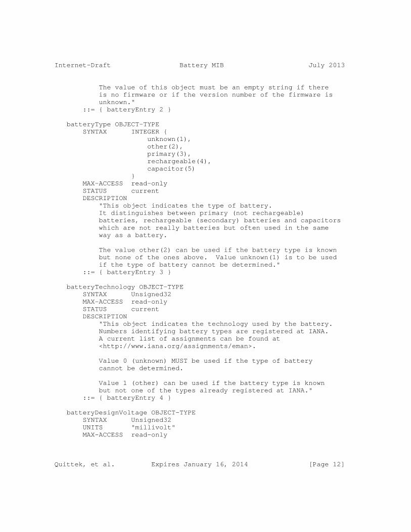
Internet-Draft Battery MIB July 2013
The value of this object must be an empty string if there is no firmware or if the version number of the firmware is unknown." ::= { batteryEntry 2 }
batteryType OBJECT-TYPE SYNTAX INTEGER { unknown(1), other(2), primary(3), rechargeable(4), capacitor(5) } MAX-ACCESS read-only STATUS current DESCRIPTION "This object indicates the type of battery. It distinguishes between primary (not rechargeable) batteries, rechargeable (secondary) batteries and capacitors which are not really batteries but often used in the same way as a battery.
The value other(2) can be used if the battery type is known but none of the ones above. Value unknown(1) is to be used if the type of battery cannot be determined." ::= { batteryEntry 3 }
batteryTechnology OBJECT-TYPE SYNTAX Unsigned32 MAX-ACCESS read-only STATUS current DESCRIPTION "This object indicates the technology used by the battery. Numbers identifying battery types are registered at IANA. A current list of assignments can be found at <http://www.iana.org/assignments/eman>.
Value 0 (unknown) MUST be used if the type of battery cannot be determined.
Value 1 (other) can be used if the battery type is known but not one of the types already registered at IANA." ::= { batteryEntry 4 }
batteryDesignVoltage OBJECT-TYPE SYNTAX Unsigned32 UNITS "millivolt" MAX-ACCESS read-only
Quittek, et al. Expires January 16, 2014 [Page 12]

Internet-Draft Battery MIB July 2013
STATUS current DESCRIPTION "This object provides the design (or nominal) voltage of the battery in units of millivolt (mV).
Note that the design voltage is a constant value and typically different from the actual voltage of the battery.
A value of 0 indicates that the design voltage is unknown." ::= { batteryEntry 5 }
batteryNumberOfCells OBJECT-TYPE SYNTAX Unsigned32 MAX-ACCESS read-only STATUS current DESCRIPTION "This object indicates the number of cells contained in the battery.
A value of 0 indicates that the number of cells is unknown." ::= { batteryEntry 6 }
batteryDesignCapacity OBJECT-TYPE SYNTAX Unsigned32 UNITS "milliampere hours" MAX-ACCESS read-only STATUS current DESCRIPTION "This object provides the design (or nominal) capacity of the battery in units of milliampere hours (mAh).
Note that the design capacity is a constant value and typically different from the actual capacity of the battery. Usually, this is a value provided by the manufacturer of the battery.
A value of 0 indicates that the design capacity is unknown." ::= { batteryEntry 7 }
batteryMaxChargingCurrent OBJECT-TYPE SYNTAX Unsigned32 UNITS "milliampere" MAX-ACCESS read-only STATUS current DESCRIPTION "This object provides the maximal current to be used for charging the battery in units of milliampere (mA).
Quittek, et al. Expires January 16, 2014 [Page 13]

Internet-Draft Battery MIB July 2013
Note that the maximal charging current may not lead to optimal charge of the battery and that some batteries can only be charged with the maximal current for a limited amount of time.
A value of 0 indicates that the maximal charging current is unknown." ::= { batteryEntry 8 }
batteryTrickleChargingCurrent OBJECT-TYPE SYNTAX Unsigned32 UNITS "milliampere" MAX-ACCESS read-only STATUS current DESCRIPTION "This object provides the recommended current to be used for trickle charging the battery in units of milliampere (mA).
Typically, this is a value recommended by the manufacturer of the battery or by the manufacturer of the charging circuit.
A value of 0 indicates that the recommended trickle charging current is unknown." ::= { batteryEntry 9 }
batteryActualCapacity OBJECT-TYPE SYNTAX Unsigned32 UNITS "milliampere hours" MAX-ACCESS read-only STATUS current DESCRIPTION "This object provides the actual capacity of the battery in units of milliampere hours (mAh).
Typically, the actual capacity of a battery decreases with time and with usage of the battery. It is usually lower than the design capacity
Note that the actual capacity needs to be measured and is typically an estimate based on observed discharging and charging cycles of the battery.
A value of ’ffffffff’H indicates that the actual capacity cannot be determined." ::= { batteryEntry 10 }
batteryChargingCycleCount OBJECT-TYPE
Quittek, et al. Expires January 16, 2014 [Page 14]

Internet-Draft Battery MIB July 2013
SYNTAX Unsigned32 MAX-ACCESS read-only STATUS current DESCRIPTION "This object indicates the number of completed charging cycles that the battery underwent. In line with the Smart Battery Data Specification Revision 1.1, a charging cycle is defined as the process of discharging the battery by a total amount equal to the battery design capacity as given by object batteryDesignCapacity. A charging cycle may include several steps of charging and discharging the battery until the discharging amount given by batteryDesignCapacity has been reached. As soon as a charging cycle has been completed the next one starts immediately independent of the battery’s current charge at the end of the cycle.
For batteries of type primary(1) the value of this object is always 0.
A value of ’ffffffff’H indicates that the number of charging cycles cannot be determined." ::= { batteryEntry 11 }
batteryLastChargingCycleTime OBJECT-TYPE SYNTAX DateAndTime MAX-ACCESS read-only STATUS current DESCRIPTION "The date and time of the last charging cycle. The value ’0000000000000000’H is returned if the battery has not been charged yet or if the last charging time cannot be determined.
For batteries of type primary(1) the value of this object is always ’0000000000000000’H." ::= { batteryEntry 12 }
batteryChargingOperState OBJECT-TYPE SYNTAX INTEGER { unknown(1), charging(2), fastCharging(3), maintainingCharge(4), noCharging(5), discharging(6) }
Quittek, et al. Expires January 16, 2014 [Page 15]

Internet-Draft Battery MIB July 2013
MAX-ACCESS read-only STATUS current DESCRIPTION "This object indicates the current charging state of the battery.
Value unknown(1) indicates that the charging state of the battery cannot be determined.
Value charging(2) indicates that the battery is being charged in a way that the charge of the battery increases.
Value fastCharging(3) indicated that the battery is being charged rapidly, i.e. faster than in the charging(2) state. If multiple fast charging states exist, all of these states are indicated by fastCharging(3).
Value maintainingCharge(4) indicates that the battery is being charged with a low current that compensates self-discharging. This includes trickle charging, float charging and other methods for maintaining the current charge of a battery.
Value noCharging(5) indicates that the battery is not being charged or discharged by electric current between the battery and electric circuits external to the battery. Note that the battery may still be subject to self-discharging.
Value discharging(6) indicates that the battery is being discharged and that the charge of the battery decreases." ::= { batteryEntry 13 }
batteryChargingAdminState OBJECT-TYPE SYNTAX INTEGER { charging(2), fastCharging(3), maintainingCharge(4), noCharging(5), discharging(6), notSet(7) } MAX-ACCESS read-write STATUS current DESCRIPTION "The value of this object indicates the desired status of the charging state of the battery. The real state is indicated by object batteryChargingOperState. See the
Quittek, et al. Expires January 16, 2014 [Page 16]

Internet-Draft Battery MIB July 2013
definition of object batteryChargingOperState for a description of the values.
When this object is initialized by an implementation of the BATTERY-MIB module, its value is set to notSet(7).
However, a SET request can only set this object to either charging(2), fastCharging(3), maintainingCharge(4), noCharging(5), or discharging(6). Attempts to set this object to notSet(7) will always fail with an ’inconsistentValue’ error. In case multiple fast charging states exist, the battery logic can choose an appropriate fast charging state - preferably the fastest.
When the batteryChargingAdminState object is set, then the BATTERY-MIB implementation must try to set the battery to the indicated state. The result will be indicated by object batteryChargingOperState.
Due to operational conditions and limitations of the implementation of the BATTERY-MIB module, changing the battery status according to a set value of object batteryChargingAdminState may not be possible.
Setting the value of object batteryChargingAdminState may result in not changing the state of the battery to this value or even in setting the charging state to another value. For example, setting batteryChargingAdminState to value fastCharging(3) may have no effect when the battery logic is not allowing fast charging due to temperature constraints."
::= { batteryEntry 14 }
batteryActualCharge OBJECT-TYPE SYNTAX Unsigned64TC UNITS "milliampere hours" MAX-ACCESS read-only STATUS current DESCRIPTION "This object provides the actual charge of the battery in units of milliampere hours (mAh).
Note that the actual charge needs to be measured and is typically an estimate based on observed discharging and charging cycles of the battery.
A value of ’ffffffff’H indicates that the actual charge
Quittek, et al. Expires January 16, 2014 [Page 17]

Internet-Draft Battery MIB July 2013
cannot be determined." ::= { batteryEntry 15 }
batteryActualVoltage OBJECT-TYPE SYNTAX Unsigned32 UNITS "millivolt" MAX-ACCESS read-only STATUS current DESCRIPTION "This object provides the actual voltage of the battery in units of millivolt (mV).
A value of ’ffffffff’H indicates that the actual voltage cannot be determined." ::= { batteryEntry 16 }
batteryActualCurrent OBJECT-TYPE SYNTAX Integer32 UNITS "milliampere" MAX-ACCESS read-only STATUS current DESCRIPTION "This object provides the actual charging or discharging current of the battery in units of milliampere (mA). Charging current is represented by positive values, discharging current is represented by negative values.
A value of ’7fffffff’H indicates that the actual current cannot be determined." ::= { batteryEntry 17 }
batteryTemperature OBJECT-TYPE SYNTAX Integer32 UNITS "deci-degrees Celsius" MAX-ACCESS read-only STATUS current DESCRIPTION "The ambient temperature at or near the battery.
A value of ’7fffffff’H indicates that the temperature cannot be determined." ::= { batteryEntry 18 }
batteryCellIdentifier OBJECT-TYPE SYNTAX SnmpAdminString MAX-ACCESS read-only STATUS current DESCRIPTION
Quittek, et al. Expires January 16, 2014 [Page 18]

Internet-Draft Battery MIB July 2013
"The value of this object identifies one or more cells of a battery. The format of the cell identifier may vary between different implementations. It should uniquely identify one or more cells of the indexed battery.
This object can be used for batteries, such as, for example, lithium polymer batteries for which battery controllers monitor cells individually.
This object is used by notifications of type batteryLowNotification, batteryTemperatureNotification, batteryCriticalNotification, and batteryAgingNotification. These notifications can use the value of this object to indicate the event that triggered the generation of the notification in more details by specifying a single cell or a set of cells within the battery which are specifically addressed by the notification.
An example use case for this object is a single cell in a battery that exceeds the temperature indicated by object batteryAlarmHighTemperature. In such a case, a batteryTemperatureNotification can be generated that not just indicates the battery for which the temperature is exceeded but also the particular cell.
The initial value of this object is the empty string. The value of this object is set at each time a batteryLowNotification, a batteryTemperatureNotification, a batteryCriticalNotification, or a batteryAgingNotification is generated.
When a notification is generated that does not indicate a specific cell or set of cells, the value of this object is set to the empty string." ::= { batteryEntry 19 }
batteryAlarmLowCharge OBJECT-TYPE SYNTAX Unsigned32 UNITS "milliampere hours" MAX-ACCESS read-write STATUS current DESCRIPTION "This object provides the lower threshold value for object batteryActualCharge. If the value of object batteryActualCharge falls below this threshold, a low battery alarm will be raised. The alarm procedure may include generating a batteryLowNotification.
Quittek, et al. Expires January 16, 2014 [Page 19]

Internet-Draft Battery MIB July 2013
A value of 0 indicates that no alarm will be raised for any value of object batteryActualCharge." ::= { batteryEntry 20 }
batteryAlarmLowVoltage OBJECT-TYPE SYNTAX Unsigned32 UNITS "millivolt" MAX-ACCESS read-write STATUS current DESCRIPTION "This object provides the lower threshold value for object batteryActualVoltage. If the value of object batteryActualVoltage falls below this threshold, a low battery alarm will be raised. The alarm procedure may include generating a batteryLowNotification.
A value of 0 indicates that no alarm will be raised for any value of object batteryActualVoltage." ::= { batteryEntry 21 }
batteryAlarmLowCapacity OBJECT-TYPE SYNTAX Unsigned32 UNITS "milliampere hours" MAX-ACCESS read-write STATUS current DESCRIPTION "This object provides the lower threshold value for object batteryActualCapacity. If the value of object batteryActualCapacity falls below this threshold, a battery aging alarm will be raised. The alarm procedure may include generating a batteryAgingNotification.
A value of 0 indicates that no alarm will be raised for any value of object batteryActualCapacity." ::= { batteryEntry 22 }
batteryAlarmHighCycleCount OBJECT-TYPE SYNTAX Unsigned32 MAX-ACCESS read-write STATUS current DESCRIPTION "This object provides the upper threshold value for object batteryChargingCycleCount. If the value of object batteryChargingCycleCount rises above this threshold, a battery aging alarm will be raised. The alarm procedure may include generating a batteryAgingNotification.
A value of 0 indicates that no alarm will be raised for any
Quittek, et al. Expires January 16, 2014 [Page 20]

Internet-Draft Battery MIB July 2013
value of object batteryChargingCycleCount." ::= { batteryEntry 23 }
batteryAlarmHighTemperature OBJECT-TYPE SYNTAX Integer32 UNITS "deci-degrees Celsius" MAX-ACCESS read-write STATUS current DESCRIPTION "This object provides the upper threshold value for object batteryTemperature. If the value of object batteryTemperature rises above this threshold, a battery high temperature alarm will be raised. The alarm procedure may include generating a batteryTemperatureNotification.
A value of ’7fffffff’H indicates that no alarm will be raised for any value of object batteryTemperature." ::= { batteryEntry 24 }
batteryAlarmLowTemperature OBJECT-TYPE SYNTAX Integer32 UNITS "deci-degrees Celsius" MAX-ACCESS read-write STATUS current DESCRIPTION "This object provides the lower threshold value for object batteryTemperature. If the value of object batteryTemperature falls below this threshold, a battery low temperature alarm will be raised. The alarm procedure may include generating a batteryTemperatureNotification.
A value of ’7fffffff’H indicates that no alarm will be raised for any value of object batteryTemperature." ::= { batteryEntry 25 }
--================================================================== -- 2. Notifications --==================================================================
batteryChargingStateNotification NOTIFICATION-TYPE OBJECTS { batteryChargingOperState } STATUS current DESCRIPTION "This notification can be generated when a charging state of the battery (indicated by the value of object
Quittek, et al. Expires January 16, 2014 [Page 21]

Internet-Draft Battery MIB July 2013
batteryChargingOperState) is triggered by an event other than a write action to object batteryChargingAdminState. Such an event may, for example, be triggered by a local battery controller." ::= { batteryNotifications 1 }
batteryLowNotification NOTIFICATION-TYPE OBJECTS { batteryActualCharge, batteryActualVoltage, batteryCellIdentifier } STATUS current DESCRIPTION "This notification can be generated when the current charge (batteryActualCharge) or the current voltage (batteryActualVoltage) of the battery falls below a threshold defined by object batteryAlarmLowCharge or object batteryAlarmLowVoltage, respectively.
The notification should not be sent again before the current voltage or the current charge becomes higher than the respective thresholds through charging before falling below the thresholds again.
If the low charge or voltage has been detected for a single cell or a set of cells of the battery and not for the entire battery, then object batteryCellIdentifier should be set to a value that identifies the cell or set of cells. Otherwise, the value of object batteryCellIdentifier should be set to the empty string when this notification is generated." ::= { batteryNotifications 2 }
batteryCriticalNotification NOTIFICATION-TYPE OBJECTS { batteryActualCharge, batteryActualVoltage, batteryCellIdentifier } STATUS current DESCRIPTION "This notification can be generated when the current charge of the battery falls so low that it cannot provide a power supply function anymore and below and needs to be charged first before it can be used for power supply again. threshold defined by object batteryAlarmLowCharge or object batteryAlarmLowVoltage, respectively.
Quittek, et al. Expires January 16, 2014 [Page 22]
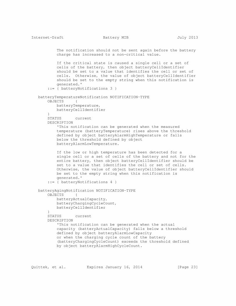
Internet-Draft Battery MIB July 2013
The notification should not be sent again before the battery charge has increased to a non-critical value.
If the critical state is caused a single cell or a set of cells of the battery, then object batteryCellIdentifier should be set to a value that identifies the cell or set of cells. Otherwise, the value of object batteryCellIdentifier should be set to the empty string when this notification is generated." ::= { batteryNotifications 3 }
batteryTemperatureNotification NOTIFICATION-TYPE OBJECTS { batteryTemperature, batteryCellIdentifier } STATUS current DESCRIPTION "This notification can be generated when the measured temperature (batteryTemperature) rises above the threshold defined by object batteryAlarmHighTemperature or falls below the threshold defined by object batteryAlarmLowTemperature.
If the low or high temperature has been detected for a single cell or a set of cells of the battery and not for the entire battery, then object batteryCellIdentifier should be set to a value that identifies the cell or set of cells. Otherwise, the value of object batteryCellIdentifier should be set to the empty string when this notification is generated." ::= { batteryNotifications 4 }
batteryAgingNotification NOTIFICATION-TYPE OBJECTS { batteryActualCapacity, batteryChargingCycleCount, batteryCellIdentifier } STATUS current DESCRIPTION "This notification can be generated when the actual capacity (batteryActualCapacity) falls below a threshold defined by object batteryAlarmLowCapacity or when the charging cycle count of the battery (batteryChargingCycleCount) exceeds the threshold defined by object batteryAlarmHighCycleCount.
Quittek, et al. Expires January 16, 2014 [Page 23]

Internet-Draft Battery MIB July 2013
If the aging has been detected for a single cell or a set of cells of the battery and not for the entire battery, then object batteryCellIdentifier should be set to a value that identifies the cell or set of cells. Otherwise, the value of object batteryCellIdentifier should be set to the empty string when this notification is generated." ::= { batteryNotifications 5 }
batteryConnectedNotification NOTIFICATION-TYPE OBJECTS { batteryIdentifier } STATUS current DESCRIPTION "This notification can be generated when it has been detected that a battery has been connected. The battery can be identified by the value of object batteryIdentifier as well as by the value of index entPhysicalIndex that is contained in the OID of object batteryIdentifier." ::= { batteryNotifications 6 }
batteryDisconnectedNotification NOTIFICATION-TYPE STATUS current DESCRIPTION "This notification can be generated when it has been detected that one or more batteries have been disconnected." ::= { batteryNotifications 7 }
--================================================================== -- 3. Conformance Information --==================================================================
batteryCompliances OBJECT IDENTIFIER ::= { batteryConformance 1 } batteryGroups OBJECT IDENTIFIER ::= { batteryConformance 2 }
-------------------------------------------------------------------- -- 3.1. Compliance Statements --------------------------------------------------------------------
batteryCompliance MODULE-COMPLIANCE STATUS current DESCRIPTION "The compliance statement for implementations of the BATTERY-MIB module.
A compliant implementation MUST implement the objects defined in the mandatory groups batteryDescriptionGroup
Quittek, et al. Expires January 16, 2014 [Page 24]

Internet-Draft Battery MIB July 2013
and batteryStatusGroup.
Note that compliance with this compliance statement requires compliance with the entity4CRCompliance MODULE-COMPLIANCE statement of the ENTITY-MIB (RFC6933)." MODULE -- this module MANDATORY-GROUPS { batteryDescriptionGroup, batteryStatusGroup }
GROUP batteryAlarmThresholdsGroup DESCRIPTION "A compliant implementation does not have to implement the batteryAlarmThresholdsGroup."
GROUP batteryNotificationsGroup DESCRIPTION "A compliant implementation does not have to implement the batteryNotificationsGroup."
GROUP batteryPerCellNotificationsGroup DESCRIPTION "A compliant implementation does not have to implement the batteryPerCellNotificationsGroup."
GROUP batteryAdminGroup DESCRIPTION "A compliant implementation does not have to implement the batteryAdminGroup."
OBJECT batteryAlarmLowCharge MIN-ACCESS read-only DESCRIPTION "The agent is not required to support set operations to this object."
OBJECT batteryAlarmLowVoltage MIN-ACCESS read-only DESCRIPTION "The agent is not required to support set operations to this object."
OBJECT batteryAlarmLowCapacity MIN-ACCESS read-only DESCRIPTION "The agent is not required to support set
Quittek, et al. Expires January 16, 2014 [Page 25]

Internet-Draft Battery MIB July 2013
operations to this object."
OBJECT batteryAlarmHighCycleCount MIN-ACCESS read-only DESCRIPTION "The agent is not required to support set operations to this object."
OBJECT batteryTemperatureNotification MIN-ACCESS read-only DESCRIPTION "The agent is not required to support set operations to this object."
::= { batteryCompliances 1 }
-------------------------------------------------------------------- -- 3.2. MIB Grouping --------------------------------------------------------------------
batteryDescriptionGroup OBJECT-GROUP OBJECTS { batteryIdentifier, batteryFirmwareVersion, batteryType, batteryTechnology, batteryDesignVoltage, batteryNumberOfCells, batteryDesignCapacity, batteryMaxChargingCurrent, batteryTrickleChargingCurrent } STATUS current DESCRIPTION "A compliant implementation MUST implement the objects contained in this group." ::= { batteryGroups 1 }
batteryStatusGroup OBJECT-GROUP OBJECTS { batteryActualCapacity, batteryChargingCycleCount, batteryLastChargingCycleTime, batteryChargingOperState, batteryActualCharge, batteryActualVoltage, batteryActualCurrent, batteryTemperature
Quittek, et al. Expires January 16, 2014 [Page 26]

Internet-Draft Battery MIB July 2013
} STATUS current DESCRIPTION "A compliant implementation MUST implement the objects contained in this group." ::= { batteryGroups 2 }
batteryAdminGroup OBJECT-GROUP OBJECTS { batteryChargingAdminState } STATUS current DESCRIPTION "A compliant implementation does not have to implement the object contained in this group." ::= { batteryGroups 3 }
batteryAlarmThresholdsGroup OBJECT-GROUP OBJECTS { batteryAlarmLowCharge, batteryAlarmLowVoltage, batteryAlarmLowCapacity, batteryAlarmHighCycleCount, batteryAlarmHighTemperature, batteryAlarmLowTemperature } STATUS current DESCRIPTION "A compliant implementation does not have to implement the objects contained in this group." ::= { batteryGroups 4 }
batteryNotificationsGroup NOTIFICATION-GROUP NOTIFICATIONS { batteryChargingStateNotification, batteryLowNotification, batteryCriticalNotification, batteryAgingNotification, batteryTemperatureNotification, batteryConnectedNotification, batteryDisconnectedNotification } STATUS current DESCRIPTION "A compliant implementation does not have to implement the notifications contained in this group." ::= { batteryGroups 5 }
Quittek, et al. Expires January 16, 2014 [Page 27]

Internet-Draft Battery MIB July 2013
batteryPerCellNotificationsGroup OBJECT-GROUP OBJECTS { batteryCellIdentifier } STATUS current DESCRIPTION "A compliant implementation does not have to implement the object contained in this group." ::= { batteryGroups 6 } END
5. Security Considerations
There are a number of management objects defined in this MIB module with a MAX-ACCESS clause of read-write. Such objects may be considered sensitive or vulnerable in some network environments. The support for SET operations in a non-secure environment without proper protection can have a negative effect on network operations. These are the tables and objects and their sensitivity/vulnerability:
o batteryChargingAdminState Setting the battery charging state can be beneficial for an operator for various reasons such as charging batteries when the price of electricity is low. However, setting the charging state can be used by an attacker to discharge batteries of devices and thereby switching these devices off if they are powered solely by batteries. In particular, if the batteryAlarmLowCharge and batteryAlarmLowVoltage can also be set, this attack will go unnoticed (i.e. no notifications are sent).
o batteryAlarmLowCharge and batteryAlarmLowVoltage These objects set the threshold for an alarm to be raised when the battery charge or voltage falls below the corresponding one of them. An attacker setting one of these alarm values can switch off the alarm by setting it to the ’off’ value 0 or modify the alarm behavior by setting it to any other value. The result may be loss of data if the battery runs empty without warning to a recipient expecting such a notification.
o batteryAlarmLowCapacity and batteryAlarmHighCycleCount These objects set the threshold for an alarm to be raised when the battery becomes older and less performant than required for stable operation. An attacker setting this alarm value can switch off the alarm by setting it to the ’off’ value 0 or modify the alarm behavior by setting it to any other value. This may either lead to a costly replacement of a working battery or too old or too weak batteries being used. The consequence of the latter could
Quittek, et al. Expires January 16, 2014 [Page 28]

Internet-Draft Battery MIB July 2013
e.g. be that a battery cannot provide power long enough between two scheduled charging actions causing the powered device to shut down and potentially lose data.
o batteryAlarmHighTemperature and batteryAlarmLowTemperature These objects set thresholds for an alarm to be raised when the battery rises above/falls below them. An attacker setting one of these alarm values can switch off these alarms by setting them to the ’off’ value ’7fffffff’H or modify the alarm behavior by setting them to any other value. The result may e.g. be an unnecessary shutdown of a device if batteryAlarmHighTemperature is set to too low or damage to the device by too high temperatures if switched off or set to too high values or by damage to the battery when it e.g. is being charged. Batteries can also be damaged e.g. in an attempt to charge them at too low temperatures.
Some of the readable objects in this MIB module (i.e., objects with a MAX-ACCESS other than not-accessible) may be considered sensitive or vulnerable in some network environments. It is thus important to control even GET and/or NOTIFY access to these objects and possibly to even encrypt the values of these objects when sending them over the network via SNMP. These are the tables and objects and their sensitivity/vulnerability:
All potentially sensible or vulnerable objects of this MIB module are in the batteryTable. In general, there are no serious operational vulnerabilities foreseen in case of an unauthorized read access to this table. However, privacy issues need to be considered. It may be a trade secret of the operator o how many batteries are installed in a managed node (batteryIndex) o how old these batteries are (batteryActualCapacity and batteryChargingCycleCount) o when the next replacement cycle for batteries can be expected (batteryAlarmLowCapacity and batteryAlarmHighCycleCount) o what battery type and make are used with which firmware version (batteryIdentifier, batteryFirmwareVersion, batteryType, and batteryTechnology)
SNMP versions prior to SNMPv3 did not include adequate security. Even if the network itself is secure (for example by using IPsec), there is no control as to who on the secure network is allowed to access and GET/SET (read/change/create/delete) the objects in this MIB module.
It is RECOMMENDED that implementers consider the security features as provided by the SNMPv3 framework (see [RFC3410], section 8), including full support for the SNMPv3 cryptographic mechanisms (for authentication and privacy).
Quittek, et al. Expires January 16, 2014 [Page 29]

Internet-Draft Battery MIB July 2013
Further, deployment of SNMP versions prior to SNMPv3 is NOT RECOMMENDED. Instead, it is RECOMMENDED to deploy SNMPv3 and to enable cryptographic security. It is then a customer/operator responsibility to ensure that the SNMP entity giving access to an instance of this MIB module is properly configured to give access to the objects only to those principals (users) that have legitimate rights to GET or SET (change/create/delete) them.
6. IANA Considerations
6.1. SMI Object Identifier Registration
The Battery MIB module defined in this document uses the following IANA-assigned OBJECT IDENTIFIER value recorded in the SMI Numbers registry:
Descriptor OBJECT IDENTIFIER value ---------- ----------------------- batteryMIB { mib-2 xxx }
[NOTE for IANA: Please allocate an object identifier at http://www.iana.org/assignments/smi-numbers for object batteryMIB.]
6.2. Battery Technology Registration
Object batteryTechnology defined in Section 4 reports battery technologies. Eighteen values for battery technologies have initially been defined. They are listed in a table in Section 3.2.
For ensuring extensibility of this list, IANA has created a registry for battery technologies at http://www.iana.org/assignments/eman and filled it with the initial list given in Section 3.2.
New assignments of numbers for battery technologies will be administered by IANA through Expert Review ([RFC5226]). Experts must check for sufficient relevance of a battery technology to be added.
[NOTE for IANA: Please create a new registry under http://www.iana.org/assignments/eman for battery types. Please fill the registry with values from the table in Section 3.2]
7. Open Issues
Quittek, et al. Expires January 16, 2014 [Page 30]

Internet-Draft Battery MIB July 2013
7.1. Battery replacement
How to deal with IDs in case of replacement of a battery? If a battery is replaced, shall the UUID in the entPhysicalTable be replaced by a new one?. Proposal: keep the UUID for the entity and use the batteryIdentifier to identify moving batteries.
7.2. Compliance statements for notifications
Compliance statements for Notifications need to be revisited and if necessary elaborated.
8. Acknowledgements
We would like to thank Steven Chew and Bill Mielke for their valuable input.
9. References
9.1. Normative References
[RFC2119] Bradner, S., "Key words for use in RFCs to Indicate Requirement Levels", BCP 14, RFC 2119, March 1997.
[RFC5226] Narten, T. and H. Alvestrand, "Guidelines for Writing an IANA Considerations Section in RFCs", BCP 26, RFC 5226, May 2008.
[RFC2578] McCloghrie, K., Ed., Perkins, D., Ed., and J. Schoenwaelder, Ed., "Structure of Management Information Version 2 (SMIv2)", STD 58, RFC 2578, April 1999.
[RFC2579] McCloghrie, K., Ed., Perkins, D., Ed., and J. Schoenwaelder, Ed., "Textual Conventions for SMIv2", STD 58, RFC 2579, April 1999.
[RFC2580] McCloghrie, K., Perkins, D., and J. Schoenwaelder, "Conformance Statements for SMIv2", STD 58, RFC 2580, April 1999.
[RFC6933] Bierman, A., Romascanu, D., Quittek, J., and M. Chandramouli, "Entity MIB (Version 4)", RFC 6933, May 2013.
Quittek, et al. Expires January 16, 2014 [Page 31]

Internet-Draft Battery MIB July 2013
9.2. Informative References
[I-D.ietf-eman-requirements] Quittek, J., Chandramouli, M., Winter, R., Dietz, T., and B. Claise, "Requirements for Energy Management", draft-ietf-eman-requirements-14 (work in progress), May 2013.
[I-D.ietf-eman-framework] Claise, B., Parello, J., Schoening, B., Quittek, J., and B. Nordman, "Energy Management Framework", draft-ietf-eman-framework-07 (work in progress), February 2013.
[I-D.ietf-eman-energy-monitoring-mib] Chandramouli, M., Schoening, B., Quittek, J., Dietz, T., and B. Claise, "Power and Energy Monitoring MIB", draft-ietf-eman-energy-monitoring-mib-05 (work in progress), April 2013.
[RFC1628] Case, J., "UPS Management Information Base", RFC 1628, May 1994.
[RFC3410] Case, J., Mundy, R., Partain, D., and B. Stewart, "Introduction and Applicability Statements for Internet- Standard Management Framework", RFC 3410, December 2002.
[SBS] "Smart Battery Data Specification", Revision 1.1, December 1998.
Authors’ Addresses
Juergen Quittek NEC Europe Ltd. NEC Laboratories Europe Network Research Division Kurfuersten-Anlage 36 Heidelberg 69115 DE
Phone: +49 6221 4342-115 Email: [email protected]
Quittek, et al. Expires January 16, 2014 [Page 32]

Internet-Draft Battery MIB July 2013
Rolf Winter NEC Europe Ltd. NEC Laboratories Europe Network Research Division Kurfuersten-Anlage 36 Heidelberg 69115 DE
Phone: +49 6221 4342-121 Email: [email protected]
Thomas Dietz NEC Europe Ltd. NEC Laboratories Europe Network Research Division Kurfuersten-Anlage 36 Heidelberg 69115 DE
Phone: +49 6221 4342-128 Email: [email protected]
Quittek, et al. Expires January 16, 2014 [Page 33]


Network Working Group J. Parello Internet-Draft B. Claise Intended Status: Standards Track Mouli Chandramouli Expires: January 12, 2014 Cisco Systems, Inc. July 12, 2013
Energy Object Context MIB draft-ietf-eman-energy-aware-mib-09
Status of this Memo
This Internet-Draft is submitted to IETF in full conformance with the provisions of BCP 78 and BCP 79.
Internet-Drafts are working documents of the Internet Engineering Task Force (IETF), its areas, and its working groups. Note that other groups may also distribute working documents as Internet-Drafts.
Internet-Drafts are draft documents valid for a maximum of six months and may be updated, replaced, or obsoleted by other documents at any time. It is inappropriate to use Internet- Drafts as reference material or to cite them other than as "work in progress."
The list of current Internet-Drafts can be accessed at http://www.ietf.org/ietf/1id-abstracts.txt
The list of Internet-Draft Shadow Directories can be accessed at http://www.ietf.org/shadow.html
This Internet-Draft will expire on January 12, 2014.

<Parello, Claise> Expires February 12, 2013 [Page 1]

Internet-Draft < Energy Object Context MIB > July 2013 Copyright Notice
Copyright (c) 2012 IETF Trust and the persons identified as the document authors. All rights reserved.
This document is subject to BCP 78 and the IETF Trust’s Legal Provisions Relating to IETF Documents (http://trustee.ietf.org/license-info) in effect on the date of publication of this document. Please review these documents carefully, as they describe your rights and restrictions with respect to this document. Code Components extracted from this document must include Simplified BSD License text as described in Section 4.e of the Trust Legal Provisions and are provided without warranty as described in the Simplified BSD License.
Abstract
This document defines a subset of a Management Information Base (MIB) for energy management of devices. The module addresses device identification, context information, and the relationships between reporting devices, remote devices, and monitoring devices.
Conventions used in this document
The key words "MUST", "MUST NOT", "REQUIRED", "SHALL", "SHALL NOT", "SHOULD", "SHOULD NOT", "RECOMMENDED", "NOT RECOMMENDED", "MAY", and "OPTIONAL" in this document are to be interpreted as described in RFC 2119 [RFC2119].
Table of Contents
1. Introduction............................................. 3 1.1. Energy Management Document Overview..................3 2. The Internet-Standard Management Framework............... 4 3. Requirements and Use Cases............................... 4 4. Terminology.............................................. 4 5. Architecture Concepts Applied to the MIB Module.......... 6 5.1 Energy Object Identification..........................9 5.2 Energy Object Context................................10 5.3 Links to Other Identifiers...........................10 5.4 Child: Energy Object Relationships...................11 5.5 Parent: Energy Object Relationships..................12 5.6 Energy Object Identity Persistence...................12
<Parello, Claise> Expires January 12, 2014 [Page 2]

Internet-Draft < Energy Object Context MIB > July 2013 6. MIB Definitions......................................... 13 7. Security Considerations................................. 29 8. IANA Considerations..................................... 30 9. Acknowledgement......................................... 30 10. References............................................. 31 10.1. Normative References...............................31 10.2. Informative References.............................32
1. Introduction
The EMAN standards provide a specification for Energy Management. This document defines a subset of a Management Information Base (MIB) for use with network management protocols for Energy monitoring of network devices and devices attached to the network and possibly extending to devices in the industrial automation setting with a network interface.
The focus of the MIB module specified in this document is on the identification of Energy Objects and reporting the context and relationships of Energy Objects as defined in [EMAN-FMWK]. The module addresses Energy Object Identification, Energy Object Context, and Energy Object Relationships.
1.1. Energy Management Document Overview
This document specifies the ENERGY-OBJECT-CONTEXT-MIB module. This document is based on the Energy Management Framework [EMAN- FMWK] and meets the requirements on identification of Energy Objects and their context and relationships as specified in the Energy Management requirements [EMAN-REQ].
A second MIB module required by the [EMAN-FMWK], the Power and Energy Monitoring MIB [EMAN-MON-MIB], monitors the Energy Objects for Power States, for the Power and Energy consumption. Power State monitoring includes: retrieving Power States, Power State properties, current Power State, Power State transitions, and Power State statistics. In addition, this MIB module provides the Power Characteristics properties of the Power and Energy, along with optional characteristics.
The applicability statement document [EMAN-AS] provides the list of use cases, and describes the common aspects of between existing Energy standards and the EMAN standard, and shows how the EMAN framework relates to other frameworks.
<Parello, Claise> Expires January 12, 2014 [Page 3]

Internet-Draft < Energy Object Context MIB > July 2013 2. The Internet-Standard Management Framework
For a detailed overview of the documents that describe the current Internet-Standard Management Framework, please refer to section 7 of RFC 3410 [RFC3410].
Managed objects are accessed via a virtual information store, termed the Management Information Base or MIB. MIB objects are generally accessed through the Simple Network Management Protocol (SNMP). Objects in the MIB are defined using the mechanisms defined in the Structure of Management Information (SMI). This memo specifies MIB modules that are compliant with SMIv2, which is described in STD 58, RFC 2578 [RFC2578], STD 58, RFC 2579 [RFC2579] and STD 58, RFC 2580 [RFC2580].
3. Requirements and Use Cases
Firstly, to illustrate the importance of energy monitoring in networks and secondly to list some of the important areas to be addressed by the energy management Framework, several use cases and network scenarios are presented in the EMAN applicability statement document [EMAN-AS]. In addition, for each scenario, the target devices for energy management, and how those devices powered and metered are also presented. To address the network scenarios, requirements for power and energy monitoring for networking devices are specified in [EMAN-REQ]. Based on the requirements [EMAN-REQ], the [EMAN-FMWK] presents an solution approach.
Accordingly, the scope of the MIB module in this document is in accordance to the requirements specified in [EMAN-REQ] and [EMAN-FMWK].
4. Terminology
Please refer to [EMAN-FMWK] for the definitions of the following terminology used in this draft.
Device
Component
<Parello, Claise> Expires January 12, 2014 [Page 4]

Internet-Draft < Energy Object Context MIB > July 2013 Energy Management
Energy Management System (EnMS)
ISO Energy Management System
Energy
Power
Demand
Power Characteristics
Electrical Equipment
Non-Electrical Equipment (Mechanical Equipment)
Energy Object
Electrical Energy Object
Non-Electrical Energy Object
Energy Monitoring
Energy Control
Provide Energy
Receive Energy
Power Interface
Power Inlet
Power Outlet
Energy Management Domain
Energy Object Identification
Energy Object Context
Energy Object Relationship
Aggregation Relationship
<Parello, Claise> Expires January 12, 2014 [Page 5]

Internet-Draft < Energy Object Context MIB > July 2013 Metering Relationship
Power Source Relationship
Energy Object Parent
Energy Object Child
Power State
Power State Set
Nameplate Power
5. Architecture Concepts Applied to the MIB Module
This section describes the basic concepts specified in the Energy Management Architecture [EMAN-FMWK], with specific information related to the MIB module specified in this document.
The Energy Object Context MIB module defined in this document defines MIB objects for identification of Energy Objects, and reporting context and relationship of an Energy Object. The managed objects are contained in two tables eoTable and eoRelationTable.
The first table eoTable focuses on link to the other MIB modules, context of the Energy Object. The second table eoRelationTable specifies the relationships between Energy Objects. This is a simplified representation of relationship between Energy Objects.
+- eoTable(2) | +- eoEntry(1) [entPhysicalIndex] | | | +-- r-n PethPsePortIndexOrZero eoEthPortIndex(1) | +-- r-n PethPsePortGroupIndexOrZero eoEthPortGrpIndex(2) | +-- r-n LldpPortNumberOrZero eoLldpPortNumber(3) | +-- rwn MacAddress eoMgmtMacAddress(4) | +-- r-n InetAddressType eoMgmtAddressType(5) | +-- r-n InetAddress eoMgmtAddress(6)
<Parello, Claise> Expires January 12, 2014 [Page 6]

Internet-Draft < Energy Object Context MIB > July 2013 | +-- r-n SnmpAdminString eoMgmtDNSName(7) | +-- rwn SnmpAdminString eoDomainName(8) | +-- rwn SnmpAdminString eoRoleDescription(9) | +-- rwn EnergyObjectKeywordList eoKeywords(10) | +-- rwn Integer32 eoImportance(11) | +-- r-n INTEGER eoPowerCategory(12) | +-- rwn SnmpAdminString eoAlternateKey(13) | | +- eoRelationTable(2) | | | +- eoRelationEntry(1) [entPhysicalIndex, eoRelationIndex] | | | | | +-- --n Integer32 eoRelationIndex(1) | | +-- --n UUIDorZero eoRelationID(2) | | +-- rwn IANAEnergyRelationship eoRelationship(3)
The following UML diagram illustrates the relationship of the MIB objects in the eoTable, eoRelationTable that describe the identity, context and relationship of an Energy Object.
+--------------------------+ | EO Context Information | | ------------------------ | | eoRoleDescription | | eoKeywords | | eoImportance | | eoPowerCategory | +--------------------------+ | | v +------------------------------+ |---> | EO Identification | | |----------------------------- | | | entPhysicalIndex (*) | | | entPhysicalName (*) | | | entPhysicalUUID (*) | | | | | | eoEthPortIndex (**) | | | eoEthPortGrpIndex (**) | | | eoLldpPortNumber (***) | | | eoAlternateKey |
<Parello, Claise> Expires January 12, 2014 [Page 7]

Internet-Draft < Energy Object Context MIB > July 2013 | | | | | eoMgmtMacAddress (optional) | | | eoMgmtAddressType (optional) | | | eoMgmtAddress (optional) | | | eoMgmtDNSName (optional) | | | eoDomainName | | +-------------------------------+ | | +------------------------------+ |---- | EO Relationship | | | ---------------------------- | | | eoRelationIndex | | | eoRelationID | | | IANAEnergyRelationship | | +------------------------------+
(*) Compliance with the ENTITY MIB V4 [RFC6933] (**) Link with the Power over Ethernet MIB [RFC3621] (***) Link with LLDP MIBs [LLDP-MIB] [LLDP-MED-MIB]
Figure 1: MIB Objects Grouping
As displayed in figure 1, the MIB objects can be classified in different logical grouping of MIB objects.
1) The Energy Object Identification. See Section 5.1 "Energy Object Identification". Devices and their sub-components are characterized by the power-related attributes of a physical entity present in the ENTITY MIB [RFC6933]. 2) The Context Information. See Section 5.2 "Energy Object Context" 3) The links to other MIB modules. See Section 5.3 "Links to other Identifiers" 4) The Energy Object Child Relationships specific information. See Section 5.4 "Child: Energy Objects Relationship." 5) The Energy Object Parent Relationships specific information. See Section 5.5 "Parent: Energy Objects Relationship." 6) The Energy Object Identity Persistence. See Section 5.6 "Energy Object Identity Persistence"
<Parello, Claise> Expires January 12, 2014 [Page 8]

Internet-Draft < Energy Object Context MIB > July 2013 5.1 Energy Object Identification
Refer to the "Energy Object Information" section in [EMAN-FMWK] for background information about Energy Objects.
Every Energy Object MUST implement the unique index, entPhysicalIndex, entPhysicalName and entPhysicalUUID from the ENTITY MIB [RFC6933]. Module Compliance with respect to entity4CRCompliance of ENTITY-MIB should be supported which require a limited number of objects supported (entPhysicalClass, entPhysicalName, entPhysicalUUID). entPhysicalIndex is used as index for the primary Energy Object information in the ENERGY- OBJECT-CONTEXT-MIB module.
Every Energy Object MUST have a printable name assigned to it. Energy Objects MUST implement the entPhysicalName object specified in the ENTITY-MIB [RFC6933], which must contain the Energy Object name.
For the ENERGY-OBJECT-CONTEXT-MIB compliance, every Energy Object instance MUST implement the entPhysicalUUID from the ENTITY MIB [RFC6933].
As displayed in [RFC4122], the following is an example of the string representation of a UUID as a URN: urn:uuid:f81d4fae- 7dec-11d0-a765-00a0c91e6bf6.
For example, to understand the relationship between Energy Object Components and Energy Objects, the ENTITY-MIB physical containment tree [RFC6933] MUST be implemented. A second example deals with one of the ENTITY-MIB extensions: if the Energy Object temperature is required, the managed objects from the ENTITY-SENSOR-MIB [RFC3433] should be supported. When an Energy Object Parent acts as a Power Aggregator the Energy Object Parent and its Energy Object Child/Children MUST be members of the same Energy Management Domain, specified by the eoDomainName MIB Object.
Each Energy Object MUST belong to a single Energy Management Domain or in other words, an Energy Object cannot belong to more than one Energy Management Domain. Refer to the "Energy Management Domain" section in [EMAN-FMWK] for background information. The eoDomainName, which is an element of the eoTable, is a read-write MIB object. The Energy Management Domain should map 1-1 with a metered or sub-metered portion of the network. The Energy Management Domain MUST be configured on the Energy Object Parent. The Energy Object Children MAY inherit
<Parello, Claise> Expires January 12, 2014 [Page 9]

Internet-Draft < Energy Object Context MIB > July 2013 the some of the domain parameters (possibly domain name, some of the context information such as role or keywords, importance) from the Energy Object Parent or the Energy Management Domain MAY be configured directly in an Energy Object Child.
5.2 Energy Object Context
Refer to the "Energy Object Context" section in [EMAN-FMWK] for background information.
An Energy Object must provide a value for eoImportance in the range of 1...100 to help differentiate the use or relative value of the device. The importance range is from 1 (least important) to 100 (most important). The default importance value is 1.
An Energy Object can provide a set of eoKeywords. These keywords are a list of tags that can be used for grouping and summary reporting within or between Energy Management Domains.
An Energy Object can be classified based on the physical properties of the Energy Object. That Energy Object can be classified as consuming power or supplying power to other devices or that Energy Object can perform both of those functions and finally, an Energy Object can be a passive meter.
Additionally, an Energy Object can provide an eoRoleDescription string that indicates the purpose the Energy Object serves in the network.
5.3 Links to Other Identifiers
While the entPhysicalIndex is the primary index for all MIB objects in the ENERGY-OBJECT-CONTEXT-MIB module, the Energy Management Systems (EnMS) must be able to make the link with the identifier(s) in other supported MIB modules.
If the Energy Object is a PoE port, and if the Power over Ethernet MIB [RFC3621] is supported by the Energy Object SNMP agent, then the Energy Object eoethPortIndex and eoethPortGrpIndex MUST contain the values of pethPsePortIndex and pethPsePortGroupIndex [RFC3621].
The Energy Object eoLldpPortNumber MUST contain the lldpLocPortNum from the LLDP MIB [LLDP-MIB], if the LLDP-MED MIB is supported on the Energy Object SNMP agent.
<Parello, Claise> Expires January 12, 2014 [Page 10]

Internet-Draft < Energy Object Context MIB > July 2013 The intent behind the links to the other MIB module identifier(s) is to correlate the instances in the different MIB modules. This will allow the ENERGY-OBJECT-CONTEXT-MIB MIB module to reference other MIB modules in cases where the Power over Ethernet and the LLDP MIB modules are supported by the SNMP agent. Some use cases may not implement any of these two MIB modules for the Energy Objects. However, in situation where any of these two MIB modules are implemented, the EnMS must be able to correlate the instances in the different MIB modules.
The eoAlternateKey alternate key object specifies a manufacturer defined string that can be used to identify the Energy Object. Since EnMS may need to correlate objects across management systems, this alternate key is provided to facilitate such a link. This optional value is intended as a foreign key or alternate identifier for a manufacturer or EnMS to use to correlate the unique Energy Object Id in other systems or namespaces. If an alternate key is not available or is not applicable then the value is the zero-length string.
5.4 Child: Energy Object Relationships
Refer to the "Energy Object Parent and Child" section in [EMAN- FMWK] for the definition and background information. In order to link the Energy Object Child and the Energy Object Parent, a separate table (eoRelationTable) has been introduced in this MIB module. The following relationships between Energy objects have been considered in the eoRelationTable.
Metering Relationship -> meteredBy, metering
Power Source Relationship -> poweredBy, powering
Aggregation Relationship -> aggregatedBy, aggregating
Each Energy object can have one or more Energy Object relationships with other Energy Objects. Depending on the direction of the relationship, an Energy Object can be considered as an Energy Object Parent or an Energy Object Child. The relationship between the Energy Objects is specified with an arbitrary index and the UUID of the remote Energy Object. The UUID MUST comply to the RFC 4122 specifications. It is
<Parello, Claise> Expires January 12, 2014 [Page 11]

Internet-Draft < Energy Object Context MIB > July 2013 important to note that it is possible that an Energy Object may not have an Energy Object relationship with other Energy Objects.
Since the communication between the Energy Object Parent and Energy Object Child may not be SNMP and is left to the choice of the device manufacturer (as defined in EMAN-FMWK), an Energy Object Child can have additional MIB objects that can be used for easier identification by the EnMS. The optional objects eoMgmtMacAddress, eoMgmtAddressType eoMgmtDNSName can be used to help identify the relationship between the child and other NMS objects. These objects can be used as an alternate key to help link the Energy Object with other keyed information that may be stored within the EnMS(s). For the optional objects that may not be included in some vendor implementations, the expected behavior when those objects are polled is noSuchInstance response.
5.5 Parent: Energy Object Relationships
When the Energy Object is an Energy Object Parent, the relationship table specifies the relationships to every Energy Object children. The explicit relationship between the Energy Object parent and each Energy Object child can be powering, metering and aggregating.
5.6 Energy Object Identity Persistence
In some situations, the Energy Object identity information should be persistent even after a device reload. For example, in a static setup where a switch monitors a series of connected PoE phones, there is a clear benefit for the EnMS if the Energy Object Identification and all associated information persist, as it saves a network discovery. However, in other situations, such as a wireless access point monitoring the mobile user PCs, there is not much advantage to persist the Energy Object Information. The identity information of an Energy Object should be persisted and there is value in the writable MIB objects persisted.
<Parello, Claise> Expires January 12, 2014 [Page 12]

Internet-Draft < Energy Object Context MIB > July 2013 6. MIB Definitions
-- ************************************************************ -- -- -- This MIB is used for describing the identity and the -- context information of Energy Objects in network -- -- -- *************************************************************
ENERGY-OBJECT-CONTEXT-MIB DEFINITIONS ::= BEGIN
IMPORTS MODULE-IDENTITY, OBJECT-TYPE, mib-2, Integer32 FROM SNMPv2-SMI TEXTUAL-CONVENTION, MacAddress, TruthValue FROM SNMPv2-TC MODULE-COMPLIANCE, OBJECT-GROUP FROM SNMPv2-CONF SnmpAdminString FROM SNMP-FRAMEWORK-MIB InetAddressType, InetAddress FROM INET-ADDRESS-MIB entPhysicalIndex FROM ENTITY-MIB UUIDorZero FROM UUID-TC-MIB IANAEnergyRelationship FROM IANA-ENERGY-RELATION-MIB;
energyAwareMIB MODULE-IDENTITY LAST-UPDATED "201306300000Z"
ORGANIZATION "IETF EMAN Working Group" CONTACT-INFO "WG Charter: http://datatracker.ietf.org/wg/eman/charter/
Mailing Lists: General Discussion: [email protected]
<Parello, Claise> Expires January 12, 2014 [Page 13]

Internet-Draft < Energy Object Context MIB > July 2013 To Subscribe: https://www.ietf.org/mailman/listinfo/eman Archive: http://www.ietf.org/mail-archive/web/eman
Editors: John Parello Cisco Systems, Inc. 3550 Cisco Way San Jose, California 95134 US Phone: +1 408 525 2339 Email: [email protected]
Benoit Claise Cisco Systems, Inc. De Kleetlaan 6a b1 Degem 1831 Belgium Phone: +32 2 704 5622 Email: [email protected]
Mouli Chandramouli Cisco Systems, Inc. Sarjapur Outer Ring Road Bangalore 560103 IN Phone: +91 80 4429 2409 Email: [email protected]"
DESCRIPTION "This MIB is used for describing the identity and the context information of Energy Objects" REVISION "201306300000Z" DESCRIPTION "Initial version, published as RFC XXXX."
::= { mib-2 xxxxx }
energyAwareMIBNotifs OBJECT IDENTIFIER ::= { energyAwareMIB 0 }
<Parello, Claise> Expires January 12, 2014 [Page 14]

Internet-Draft < Energy Object Context MIB > July 2013 energyAwareMIBObjects OBJECT IDENTIFIER ::= { energyAwareMIB 2 }
energyAwareMIBConform OBJECT IDENTIFIER ::= { energyAwareMIB 3 }
-- Textual Conventions
PethPsePortIndexOrZero ::= TEXTUAL-CONVENTION DISPLAY-HINT "d" STATUS current DESCRIPTION "This textual convention is an extension of the pethPsePortIndex convention, which defines a greater than zero value used to identify a power Ethernet PSE port. This extension permits the additional value of zero. The semantics of the value zero are object-specific and must, therefore, be defined as part of the description of any object that uses this syntax. Examples of the usage of this extension are situations where none or all physical entities need to be referenced." SYNTAX Integer32 (0..2147483647)
PethPsePortGroupIndexOrZero ::= TEXTUAL-CONVENTION DISPLAY-HINT "d" STATUS current DESCRIPTION "This textual convention is an extension of the pethPsePortGroupIndex convention from the Power Over Ethernet MIB [RFC3621], which defines a greater than zero value used to identify group containing the port to which a power Ethernet PSE is connected. This extension permits the additional value of zero. The semantics of the value zero are object-specific and must, therefore, be defined as part of the description of any object that uses this syntax. Examples of the usage of this extension are situations where none or all physical entities need to be referenced." SYNTAX Integer32 (0..2147483647)
<Parello, Claise> Expires January 12, 2014 [Page 15]

Internet-Draft < Energy Object Context MIB > July 2013 LldpPortNumberOrZero ::= TEXTUAL-CONVENTION DISPLAY-HINT "d" STATUS current DESCRIPTION "This textual convention is an extension of the LldpPortNumber convention specified in the LLDP MIB, which defines a greater than zero value used to uniquely identify each port contained in the chassis (that is known to the LLDP agent) by a port number. This extension permits the additional value of zero. The semantics of the value zero are object-specific and must, therefore, be defined as part of the description of any object that uses this syntax. Examples of the usage of this extension are situations where none or all physical entities need to be referenced." SYNTAX Integer32(0..4096)
EnergyObjectKeywordList ::= TEXTUAL-CONVENTION STATUS current DESCRIPTION "A list of keywords that can be used to group Energy Objects for reporting or searching. If multiple keywords are present, then this string will contain all the keywords separated by the ’,’ character. All alphanumeric characters and symbols (other than a comma), such as #, (, $, !, and &, are allowed. White spaces before and after the commas are ignored, as well as within a keyword itself.
For example, if an Energy Object were to be tagged with the keyword values ’hospitality’ and ’guest’, then the keyword list will be ’hospitality,guest’." SYNTAX OCTET STRING (SIZE (0..2048))
EnergyRelations ::= TEXTUAL-CONVENTION STATUS current DESCRIPTION "This object specifies relationship between Energy Objects. For example, poweredby relationship indicates, Energy Object A is powered by Energy Object B. From the
<Parello, Claise> Expires January 12, 2014 [Page 16]

Internet-Draft < Energy Object Context MIB > July 2013 point of view of Energy Object B, it is powering Energy Object A. " SYNTAX BITS { none (0), -- poweredby(1), -- power relationship powering(2), meteredby(3), -- meter relationship metering(4), aggregatedby(7), -- aggregation relationship aggregating(8) }
-- Objects
eoTable OBJECT-TYPE SYNTAX SEQUENCE OF EoEntry MAX-ACCESS not-accessible STATUS current DESCRIPTION "This table lists Energy Objects." ::= { energyAwareMIBObjects 2 }
eoEntry OBJECT-TYPE SYNTAX EoEntry MAX-ACCESS not-accessible STATUS current DESCRIPTION "An entry describes the attributes of an Energy Object. Whenever a new Energy Object is added or an existing Energy Object is deleted, a row in the eoTable is added or deleted."
INDEX {entPhysicalIndex } ::= { eoTable 1 }
EoEntry ::= SEQUENCE { eoEthPortIndex PethPsePortIndexOrZero, eoEthPortGrpIndex PethPsePortGroupIndexOrZero, eoLldpPortNumber LldpPortNumberOrZero, eoMgmtMacAddress MacAddress, eoMgmtAddressType InetAddressType, eoMgmtAddress InetAddress, eoMgmtDNSName SnmpAdminString, eoDomainName SnmpAdminString,
<Parello, Claise> Expires January 12, 2014 [Page 17]

Internet-Draft < Energy Object Context MIB > July 2013 eoRoleDescription SnmpAdminString, eoKeywords EnergyObjectKeywordList, eoImportance Integer32, eoPowerCategory INTEGER, eoAlternateKey SnmpAdminString
}
eoEthPortIndex OBJECT-TYPE SYNTAX PethPsePortIndexOrZero MAX-ACCESS read-only STATUS current DESCRIPTION "This variable uniquely identifies the power Ethernet port to which the attached device is connected [RFC3621]. In addition, PoE MIB should be instantiated on the device. If such a power Ethernet port cannot be specified or is not known then the object is zero." ::= { eoEntry 1 }
eoEthPortGrpIndex OBJECT-TYPE SYNTAX PethPsePortGroupIndexOrZero MAX-ACCESS read-only STATUS current DESCRIPTION "This variable uniquely identifies the group containing the port to which a power Ethernet PSE is connected [RFC3621]. In addition, PoE MIB should be instantiated on the device. If such a group cannot be specified or is not known then the object is zero." ::= { eoEntry 2 }
eoLldpPortNumber OBJECT-TYPE SYNTAX LldpPortNumberOrZero MAX-ACCESS read-only STATUS current DESCRIPTION "This variable uniquely identifies the port component (contained in the local chassis with the LLDP agent) as defined by the lldpLocPortNum in the [LLDP-MIB] and [LLDP-MED-MIB]. In addition, LLDP MIB should be instantiated on the device If such a port number cannot be specified or is not known then the object is zero." ::= { eoEntry 3 }
eoMgmtMacAddress OBJECT-TYPE
<Parello, Claise> Expires January 12, 2014 [Page 18]

Internet-Draft < Energy Object Context MIB > July 2013 SYNTAX MacAddress MAX-ACCESS read-only STATUS current DESCRIPTION "This object specifies a MAC address of the Energy Object. This object typically only applies to Energy Object Children. This object can be used as an alternate key to help link the Energy Object with other keyed information that may be stored within the EnMS(s). The eoMgmtMacAddress MIB object SHOULD be implemented for Energy Object Children, and MAY be implemented for Energy Object Parents." ::= { eoEntry 4 }
eoMgmtAddressType OBJECT-TYPE SYNTAX InetAddressType MAX-ACCESS read-only STATUS current DESCRIPTION "This object specifies the eoMgmtAddress type, i.e. an IPv4 address or an IPv6 address. This object MUST be populated when eoMgmtAddress is populated. The eoMgmtAddressType MIB object SHOULD be implemented for Energy Object Children, and MAY be implemented for Energy Object Parents." ::= { eoEntry 5 }
eoMgmtAddress OBJECT-TYPE SYNTAX InetAddress MAX-ACCESS read-only STATUS current DESCRIPTION "This object specifies the management address as an IPv4 address or IPv6 address of Energy Object. The IP address type, i.e. IPv4 or IPv6, is determined by the eoMgmtAddressType value. This object can be used as an alternate key to help link the Energy Object with other keyed information that may be stored within the EnMS(s). The eoMgmtAddress MIB object SHOULD be implemented for Energy Object Children, and MAY be implemented for Energy Object Parents." ::= { eoEntry 6 }
eoMgmtDNSName OBJECT-TYPE SYNTAX SnmpAdminString
<Parello, Claise> Expires January 12, 2014 [Page 19]

Internet-Draft < Energy Object Context MIB > July 2013 MAX-ACCESS read-only STATUS current DESCRIPTION "This object specifies the DNS name of the eoMgmtAddress. This object can be used as an alternate key to help link the Energy Object with other keyed information that may be stored within the EnMS(s). The eoMgmtDNSName MIB objects SHOULD be implemented for Energy Object Children, and MAY be implemented for Energy Object Parents."
::= { eoEntry 7 }
eoDomainName OBJECT-TYPE SYNTAX SnmpAdminString MAX-ACCESS read-write STATUS current DESCRIPTION "This object specifies the name of an Energy Management Domain for the Energy Object. This object specifies a zero-length string value if no Energy Management Domain name is configured. The value of eoDomainName must remain constant at least from one re-initialization of the entity local management system to the next re- initialization." ::= { eoEntry 8 }
eoRoleDescription OBJECT-TYPE SYNTAX SnmpAdminString MAX-ACCESS read-write STATUS current DESCRIPTION "This object specifies an administratively assigned name to indicate the purpose an Energy Object serves in the network.
For example, we can have a phone deployed to a lobby with eoRoleDescription as ’Lobby phone’.
This object specifies the value is the zero-length string value if no role description is configured. The value of eoRoleDescription must remain constant at least from one re-initialization of the entity local management system to the next re-initialization. " ::= { eoEntry 9 }
eoKeywords OBJECT-TYPE
<Parello, Claise> Expires January 12, 2014 [Page 20]

Internet-Draft < Energy Object Context MIB > July 2013 SYNTAX EnergyObjectKeywordList MAX-ACCESS read-write STATUS current DESCRIPTION "This object specifies a list of keywords that can be used to group Energy Objects for reporting or searching. The value is the zero-length string if no keywords have been configured. If multiple keywords are present, then this string will contain all the keywords separated by the ’,’ character. For example, if an Energy Object were to be tagged with the keyword values ’hospitality’ and ’guest’, then the keyword list will be ’hospitality,guest’.
If write access is implemented and a value is written into the instance, the agent must retain the supplied value in the eoKeywords instance associated with the same physical entity for as long as that entity remains instantiated. This includes instantiations across all re-initializations/reboots of the local management agent. " ::= { eoEntry 10 }
eoImportance OBJECT-TYPE SYNTAX Integer32 (1..100) MAX-ACCESS read-write STATUS current DESCRIPTION "This object specifies a ranking of how important the Energy Object is (on a scale of 1 to 100) compared with other Energy Objects in the same Energy Management Domain. The ranking should provide a business or operational context for the Energy Object as compared to other similar Energy Objects. This ranking could be used as input for policy-based network management.
Although network managers must establish their own ranking, the following is a broad recommendation:
90 to 100 Emergency response 80 to 90 Executive or business critical 70 to 79 General or Average 60 to 69 Staff or support 40 to 59 Public or guest 1 to 39 Decorative or hospitality
<Parello, Claise> Expires January 12, 2014 [Page 21]

Internet-Draft < Energy Object Context MIB > July 2013 The value of eoImportance must remain constant at least from one re-initialization of the entity local management system to the next re-initialization. " DEFVAL { 1 } ::= { eoEntry 11 }
eoPowerCategory OBJECT-TYPE SYNTAX INTEGER { consumer(0), producer(1), consumerproducer(2), meter(3) } MAX-ACCESS read-only STATUS current DESCRIPTION "This object describes the Energy Object category, which indicates the expected behavior or physical property of the Energy Object, based on its design. An Energy Object can be a consumer(0), producer(1), or consumerproducer (2) or meter (3).
There are devices with a dual mode - consuming energy and producing of energy and those are identified as consumerproducer.
In some cases, a meter is required to measure the power consumption. In such a case, this meter Energy Object category is meter(3). " ::= { eoEntry 12 }
eoAlternateKey OBJECT-TYPE SYNTAX SnmpAdminString MAX-ACCESS read-write STATUS current DESCRIPTION "This object specifies a manufacturer defined string that can be used to identify the Energy Object. Since Energy Management Systems (EnMS) and Network Management Systems (NMS) may need to correlate objects across management systems, this alternate key is provided to provide such a link. This optional value is intended as a foreign key or alternate identifier for a manufacturer or EnMS/NMS to use to correlate the unique Energy Object Id in other systems or namespaces. If an alternate key is not available or is not applicable then the value is the zero-length string. The value of eoAlternateKey must remain constant at
<Parello, Claise> Expires January 12, 2014 [Page 22]

Internet-Draft < Energy Object Context MIB > July 2013 least from one re-initialization of the entity local management system to the next re-initialization. " ::= { eoEntry 13 }
eoRelationTable OBJECT-TYPE SYNTAX SEQUENCE OF EoRelationEntry MAX-ACCESS not-accessible STATUS current DESCRIPTION "This table describes the relationships between Energy Objects." ::= { energyAwareMIBObjects 3 }
eoRelationEntry OBJECT-TYPE SYNTAX EoRelationEntry MAX-ACCESS not-accessible STATUS current DESCRIPTION "An entry in this table describes the relationship between Energy objects." INDEX { entPhysicalIndex, eoRelationIndex } ::= { eoRelationTable 1 }
EoRelationEntry ::= SEQUENCE { eoRelationIndex Integer32, eoRelationID UUIDorZero, eoRelationship IANAEnergyRelationship }
eoRelationIndex OBJECT-TYPE SYNTAX Integer32 (0..2147483647) MAX-ACCESS not-accessible STATUS current DESCRIPTION "This object is an arbitrary index to identify the Energy Object related to another Energy Object" ::= { eoRelationEntry 1 }
eoRelationID OBJECT-TYPE SYNTAX UUIDorZero MAX-ACCESS read-only STATUS current DESCRIPTION
"This object specifies the Universally Unique Identifier (UUID) of the peer (other) Energy Object. The UUID must comply the
<Parello, Claise> Expires January 12, 2014 [Page 23]

Internet-Draft < Energy Object Context MIB > July 2013 specifications of UUID in UUID-TC-MIB.
If UUID of the energy object is unknown or non-existent, the eoRelationID will be set to a zero-length string instead."
REFERENCE "RFC 6933, Entity MIB - version 4, May 2013 " ::= { eoRelationEntry 2 }
eoRelationship OBJECT-TYPE SYNTAX IANAEnergyRelationship MAX-ACCESS read-write STATUS current DESCRIPTION "This object describes the relations between Energy objects. For each Energy object, the relations between the other Energy objects are specified using the bitmap. If the Energy Object is a Parent and has no other relations, none(0) is specified." ::= { eoRelationEntry 3 }
-- Conformance
energyAwareMIBCompliances OBJECT IDENTIFIER ::= { energyAwareMIBObjects 5 }
energyAwareMIBGroups OBJECT IDENTIFIER ::= { energyAwareMIBObjects 6 }
energyAwareMIBFullCompliance MODULE-COMPLIANCE STATUS current DESCRIPTION "When this MIB is implemented with support for read-write, then such an implementation can claim full compliance. Such devices can then be both monitored and configured with this MIB."
MODULE -- this module MANDATORY-GROUPS { energyAwareMIBTableGroup, energyAwareRelationTableGroup
}
<Parello, Claise> Expires January 12, 2014 [Page 24]

Internet-Draft < Energy Object Context MIB > July 2013 GROUP energyAwareOptionalMIBTableGroup DESCRIPTION "A compliant implementation does not have to implement. Module Compliance of ENTITY-MIB with respect to entity4CRCompliance should be supported. "
::= { energyAwareMIBCompliances 1 }
energyAwareMIBReadOnlyCompliance MODULE-COMPLIANCE STATUS current DESCRIPTION "When this MIB is implemented without support for read-write (i.e. in read-only mode), then such an implementation can claim read-only compliance. Such a device can then be monitored but cannot be Configured with this MIB. Module Compliance of ENTITY-MIB with respect to entity4CRCompliance should be supported." MODULE -- this module
MANDATORY-GROUPS { energyAwareMIBTableGroup, energyAwareRelationTableGroup
}
GROUP energyAwareOptionalMIBTableGroup DESCRIPTION "A compliant implementation does not have to implement the managed objects in this GROUP. Module Compliance of ENTITY-MIB with respect to entity4CRCompliance should be supported. "
::= { energyAwareMIBCompliances 2 }
-- Units of Conformance
energyAwareMIBTableGroup OBJECT-GROUP OBJECTS {
<Parello, Claise> Expires January 12, 2014 [Page 25]

Internet-Draft < Energy Object Context MIB > July 2013 eoDomainName, eoRoleDescription, eoAlternateKey, eoKeywords, eoImportance, eoPowerCategory
} STATUS current DESCRIPTION "This group contains the collection of all the objects related to the EnergyObject. Module Compliance of ENTITY-MIB with respect to entity4CRCompliance should be supported. " ::= { energyAwareMIBGroups 1 }
energyAwareOptionalMIBTableGroup OBJECT-GROUP OBJECTS {
eoEthPortIndex, eoEthPortGrpIndex, eoLldpPortNumber, eoMgmtMacAddress, eoMgmtAddressType, eoMgmtAddress, eoMgmtDNSName } STATUS current DESCRIPTION "This group contains the collection of all the objects related to the Energy Object." ::= { energyAwareMIBGroups 2 }
energyAwareRelationTableGroup OBJECT-GROUP OBJECTS { -- Note that object eoRelationIndex is not -- included since it is not-accessible
eoRelationID, eoRelationship } STATUS current DESCRIPTION "This group contains the collection of all objects specifying the relationship between Energy Objects." ::= { energyAwareMIBGroups 3 }
<Parello, Claise> Expires January 12, 2014 [Page 26]

Internet-Draft < Energy Object Context MIB > July 2013 END
IANA-ENERGY-RELATION-MIB DEFINITIONS ::= BEGIN IMPORTS MODULE-IDENTITY, mib-2 FROM SNMPv2-SMI TEXTUAL-CONVENTION FROM SNMPv2-TC;
ianaEnergyRelationMIB MODULE-IDENTITY LAST-UPDATED "201306300000Z" -- June 30, 2013 ORGANIZATION "IANA" CONTACT-INFO " Internet Assigned Numbers Authority Postal: ICANN 4676 Admiralty Way, Suite 330 Marina del Rey, CA 90292 Tel: +1-310-823-9358 EMail: iana&iana.org"
DESCRIPTION "This MIB module defines a TEXTUAL-CONVENTION that describes the relationships between Energy Objects.
Copyright (C) The IETF Trust (2013).
The initial version of this MIB module was published in RFC yyyy; for full legal notices see the RFC itself. Supplementary information may be available at http://www.ietf.org/copyrights/ianamib.html"
REVISION "201306300000Z" -- June 30, 2013 DESCRIPTION "Initial version of this MIB as published in RFC yyyy." ::= { mib-2 xxx }
-- RFC Editor, please replace xxx with the IANA allocation -- for this MIB module and yyyy with the number of the -- approved RFC
<Parello, Claise> Expires January 12, 2014 [Page 27]

Internet-Draft < Energy Object Context MIB > July 2013 -- Textual Conventions
IANAEnergyRelationship ::= TEXTUAL-CONVENTION STATUS current DESCRIPTION
"An enumerated value specifies the type of relationship between Energy Objects.
The enumeration ’poweredBy’ is applicable if the Energy Object A is poweredBy Energy Object B.
The enumeration ’powering’ is applicable if the Energy Object A is powering Energy Object B.
The enumeration ’meteredBy’ is applicable if the Energy Object A is meteredBy Energy Object B.
The enumeration ’metering’ is applicable if the Energy Object A is metering Energy Object B.
The enumeration ’aggregatedBy’ is applicable if the Energy Object A is aggregatedBy Energy Object B.
The enumeration ’aggregating’ is applicable if the Energy Object A is aggregating Energy Object B."
SYNTAX INTEGER {
poweredBy(1), -- power relationship powering(2), meteredBy(3), -- meter relationship metering(4), aggregatedBy(5), -- aggregation relationship aggregating(6) }
<Parello, Claise> Expires January 12, 2014 [Page 28]

Internet-Draft < Energy Object Context MIB > July 2013 END
7. Security Considerations
Some of the readable objects in these MIB modules (i.e., objects with a MAX-ACCESS other than not-accessible) may be considered sensitive or vulnerable in some network environments. It is thus important to control even GET and/or NOTIFY access to these objects and possibly to even encrypt the values of these objects when sending them over the network via SNMP.
There are a number of management objects defined in these MIB modules with a MAX-ACCESS clause of read-write and/or read- create. Such objects MAY be considered sensitive or vulnerable in some network environments. The support for SET operations in a non-secure environment without proper protection can have a negative effect on network operations. The following are the tables and objects and their sensitivity/vulnerability:
. Unauthorized changes to the eoDomainName, entPhysicalName, eoRoleDescription, eoKeywords, and/or eoImportance MAY disrupt power and energy collection, and therefore any predefined policies defined in the network.
SNMP versions prior to SNMPv3 did not include adequate security. Even if the network itself is secure (for example, by using IPsec), there is still no secure control over who on the secure network is allowed to access and GET/SET (read/change/create/delete) the objects in these MIB modules.
It is RECOMMENDED that implementers consider the security features as provided by the SNMPv3 framework (see [RFC3410], section 8), including full support for the SNMPv3 cryptographic mechanisms (for authentication and privacy).
Further, deployment of SNMP versions prior to SNMPv3 is NOT RECOMMENDED. Instead, it is RECOMMENDED to deploy SNMPv3 and to enable cryptographic security. It is then a customer/operator responsibility to ensure that the SNMP entity giving access to an instance of these MIB modules is properly configured to give access to the objects only to those principals (users) that have legitimate rights to GET or SET (change/create/delete) them.
<Parello, Claise> Expires January 12, 2014 [Page 29]

Internet-Draft < Energy Object Context MIB > July 2013 8. IANA Considerations
The MIB module in this document uses the following IANA-assigned OBJECT IDENTIFIER values recorded in the SMI Numbers registry:
Descriptor OBJECT IDENTIFIER value ---------- ----------------------- energyAwareMIB { mib-2 xxx }
Additions to this MIB module are subject to Expert Review [RFC5226], i.e., review by one of a group of experts designated by an IETF Area Director. The group of experts MUST check the requested MIB objects for completeness and accuracy of the description. Requests for MIB objects that duplicate the functionality of existing objects SHOULD be declined. The smallest available OID SHOULD be assigned to a new MIB objects. The specification of new MIB objects SHOULD follow the structure specified in Section 6 and MUST be published using a well- established and persistent publication medium.
This document defines the first version of the IANA-maintained IANA-ENERGY-RELATION-MIB module, which allows new definitions of relationships between Energy Objects.
A Specification Required as defined in RFC 5226 [RFC5226], is REQUIRED for each modification of the energy relationships.
The MIB module in this document uses the following IANA-assigned OBJECT IDENTIFIER values recorded in the SMI Numbers registry:
Descriptor OBJECT IDENTIFIER value ---------- ----------------------- ianaEnergyRelationMIB { mib-2 xxx }
9. Acknowledgement
We would like to thank Juergen Quittek and Juergen Schoenwalder for their suggestions on the new design of eoRelationTable which was a proposed solution for the open issue on the representation of Energy Object children as a UUIDlist.
Many thanks to Juergen Quittek for many comments on the wording, text and design of the MIB thus resulting in an improved draft.
<Parello, Claise> Expires January 12, 2014 [Page 30]

Internet-Draft < Energy Object Context MIB > July 2013 Many thanks to Alan Luchuk for the review of the MIB and his comments.
In addition the authors thank Bill Mielke for his multiple reviews, Brad Schoening and Juergen Schoenwaelder for their suggestions and Michael Brown for dramatically improving this draft.
10. References
10.1. Normative References
[RFC2119] S. Bradner, Key words for use in RFCs to Indicate Requirement Levels, BCP 14, RFC 2119, March 1997.
[RFC2578] McCloghrie, K., Ed., Perkins, D., Ed., and J. Schoenwaelder, Ed., "Structure of Management Information Version 2 (SMIv2)", STD 58, RFC 2578, April 1999.
[RFC2579] McCloghrie, K., Ed., Perkins, D., Ed., and J. Schoenwaelder, Ed., "Textual Conventions for SMIv2", STD 58, RFC 2579, April 1999.
[RFC2580] McCloghrie, K., Perkins, D., and J. Schoenwaelder, "Conformance Statements for SMIv2", STD 58, RFC 2580, April 1999.
[RFC3621] Berger, A., and D. Romascanu, "Power Ethernet MIB", RFC3621, December 2003.
[RFC4122] Leach, P., Mealling, M., and R. Salz, "A Universally Unique IDentifier (UUID) URN Namespace ", RFC 4122, July 2005.
[RFC6933] Bierman, A. Romascanu,D. Quittek, J. and M. Chandramouli, "Entity MIB (Version 4)", RFC 6933, May 2013.
[LLDP-MIB] IEEE 802.1AB-2005, "Management Information Base module for LLDP configuration, statistics, local system data and remote systems data components", May 2005.
<Parello, Claise> Expires January 12, 2014 [Page 31]

Internet-Draft < Energy Object Context MIB > July 2013 [LLDP-MED-MIB] ANSI/TIA-1057, "The LLDP Management Information Base extension module for TIA-TR41.4 media endpoint discovery information", July 2005.
[EMAN-MON-MIB] M. Chandramouli, Schoening, B., Quittek, J., Dietz, T., and B. Claise "Power and Energy Monitoring MIB", draft-ietf-eman-energy-monitoring-mib-05, April 2013.
10.2. Informative References
[RFC3410] Case, J., Mundy, R., Partain, D., and B. Stewart, "Introduction and Applicability Statements for Internet Standard Management Framework", RFC 3410, December 2002.
[RFC3433] Bierman, A., Romascanu, D., and K.C. Norseth, "Entity Sensor Management Information Base", RFC 3433, December 2002.
[RFC5226] Narten, T. Alverstrand, H., A. and K. McCloghrie, "Guidelines for Writing an IANA Considerations Section in RFCs ", BCP 26, RFC 5226, May 2008.
[EMAN-REQ] Quittek, J., Winter, R., Dietz, T., Claise, B., and M. Chandramouli, "Requirements for Energy Management", draft-ietf-eman-requirements-14, work in progress, May 2013.
[EMAN-FMWK] Claise, B., Parello, J., Schoening, B., and J. Quittek, "Energy Management Framework", draft-ietf- eman-framework-08, work in progress, July 2013.
[EMAN-AS] Schoening, B., Chandramouli, M, and B. Nordman, "Energy Management (EMAN) Applicability Statement", draft-ietf-eman-applicability-statement-03.txt, work in progress, April 2013.
Authors’ Addresses
Benoit Claise Cisco Systems, Inc. De Kleetlaan 6a b1 Diegem 1813
<Parello, Claise> Expires January 12, 2014 [Page 32]

Internet-Draft < Energy Object Context MIB > July 2013 BE
Phone: +32 2 704 5622 Email: [email protected]
John Parello Cisco Systems, Inc. 3550 Cisco Way San Jose, California 95134 US
Phone: +1 408 525 2339 Email: [email protected]
Mouli Chandramouli Cisco Systems, Inc. Sarjapur Outer Ring Road Bangalore 560103 IN
Phone: +91 80 4429 2409 Email: [email protected]
<Parello, Claise> Expires January 12, 2014 [Page 33]

Network Working Group M. Chandramouli Internet-Draft Cisco Systems, Inc. Intended Status: Standards Track B. Schoening Expires: February 15, 2014 Independent Consultant J. Quittek T. Dietz NEC Europe Ltd. B. Claise Cisco Systems, Inc. July 15, 2013
Power and Energy Monitoring MIB draft-ietf-eman-energy-monitoring-mib-06
Status of this Memo
This Internet-Draft is submitted to IETF in full conformance with the provisions of BCP 78 and BCP 79.
Internet-Drafts are working documents of the Internet Engineering Task Force (IETF), its areas, and its working groups. Note that other groups may also distribute working documents as Internet-Drafts.
Internet-Drafts are draft documents valid for a maximum of six months and may be updated, replaced, or obsoleted by other documents at any time. It is inappropriate to use Internet- Drafts as reference material or to cite them other than as "work in progress."
The list of current Internet-Drafts can be accessed at http://www.ietf.org/ietf/1id-abstracts.txt
The list of Internet-Draft Shadow Directories can be accessed at http://www.ietf.org/shadow.html
This Internet-Draft will expire on January 2014.

<Claise, et. Al> Expires January 15, 2014 [Page 1]

Internet-Draft <Power and Energy Monitoring MIB> July 2013 Copyright Notice
Copyright (c) 2011 IETF Trust and the persons identified as the document authors. All rights reserved.
This document is subject to BCP 78 and the IETF Trust’s Legal Provisions Relating to IETF Documents (http://trustee.ietf.org/license-info) in effect on the date of publication of this document. Please review these documents carefully, as they describe your rights and restrictions with respect to this document. Code Components extracted from this document must include Simplified BSD License text as described in Section 4.e of the Trust Legal Provisions and are provided without warranty as described in the Simplified BSD License.
Abstract
This document defines a subset of the Management Information Base (MIB) for power and energy monitoring of devices.
Conventions used in this document
The key words "MUST", "MUST NOT", "REQUIRED", "SHALL", "SHALL NOT", "SHOULD", "SHOULD NOT", "RECOMMENDED", "NOT RECOMMENDED" "MAY", and "OPTIONAL" in this document are to be interpreted as described in RFC 2119 [RFC2119].
Table of Contents
1. Introduction............................................. 3 2. The Internet-Standard Management Framework............... 4 3. Use Cases................................................ 4 4. Terminology.............................................. 5 5. Architecture Concepts Applied to the MIB Module.......... 6 5.1. Energy Object Information............................. 13 5.2. Power State........................................... 14 5.2.1. Power State Set................................14 5.3. Energy Object Usage Information....................... 15 5.4. Optional Power Usage Attributes....................... 16 5.5. Optional Energy Measurement........................... 17 5.6. Fault Management...................................... 21 6. Discovery............................................... 21 7. Link with the other IETF MIBs........................... 22
<Claise, et. Al> Expires January 15, 2014 [Page 2]

Internet-Draft <Power and Energy Monitoring MIB> July 2013 7.1. Link with the ENTITY-MIB and the ENTITY-SENSOR MIB..22 7.2. Link with the ENTITY-STATE MIB......................23 7.3. Link with the POWER-OVER-ETHERNET MIB...............24 7.4. Link with the UPS MIB...............................24 7.5. Link with the LLDP and LLDP-MED MIBs................25 8. Implementation Scenario................................. 26 9. Structure of the MIB.................................... 28 10. MIB Definitions........................................ 29 11. Implementation Status.................................. 70 12. Security Considerations................................ 70 13. IANA Considerations.................................... 71 13.1. IANA Considerations for the MIB Modules.............. 71 13.2. IANA Registration of new Power State Set............. 72 13.2.1. IANA Registration of the IEEE1621 Power State Set..72 13.2.2. IANA Registration of the DMTF Power State Set......72 13.2.3. IANA Registration of the EMAN Power State Set.....73 13.3. Updating the Registration of Existing Power State Sets....................................................... 73 12. Contributors........................................... 73 13. Acknowledgment......................................... 74 14. Open Issues............................................ 74 15. References............................................. 74 15.2. Normative References...............................74 15.3. Informative References.............................75
1. Introduction
This document defines a subset of the Management Information Base (MIB) for use in energy management of devices within or connected to communication networks. The MIB modules in this document are designed to provide a model for energy management, which includes monitoring for power state and energy consumption of networked elements. This MIB takes into account the Energy Management Framework [EMAN-FMWK], which in turn, is based on the Requirements for Energy Management [EMAN-REQ].
Energy management is applicable to devices in communication networks. Target devices for this specification include (but are not limited to): routers, switches, Power over Ethernet (PoE) endpoints, protocol gateways for building management systems, intelligent meters, home energy gateways, hosts and servers, sensor proxies, etc. Target devices and the use cases for Energy Management are discussed in Energy Management Applicability Statement [EMAN-AS].
<Claise, et. Al> Expires January 15, 2014 [Page 3]

Internet-Draft <Power and Energy Monitoring MIB> July 2013 Where applicable, device monitoring extends to the individual components of the device and to any attached dependent devices. For example: A device can contain components that are independent from a power-state point of view, such as line cards, processor cards, hard drives. A device can also have dependent attached devices, such as a switch with PoE endpoints or a power distribution unit with attached endpoints.
Devices and their sub-components can be modeled using the containment tree of the ENTITY-MIB [RFC6933]. In addition, ENERGY-AWARE-MIB module [EMAN-AWARE-MIB] provides a framework for modeling the relationship between Energy Objects. It is conceivable to have implementations of ENERGY-AWARE-MIB and ENERGY-OBJECT-MIB for modeling the relationships between Energy Objects and also monitoring the Energy consumption. In some stuations, it is possible to have implementation of ENERGY- OBJECT-MIB along with the requirement of Module Compliance of ENTITY-MIB V4 [RFC6933] with respect to entity4CRCompliance should be supported which requires 3 MIB objects (entPhysicalIndex, entPhysicalName and entPhysicalUUID) MUST be implemented.
2. The Internet-Standard Management Framework
For a detailed overview of the documents that describe the current Internet-Standard Management Framework, please refer to section 7 of RFC 3410 [RFC3410].
Managed objects are accessed via a virtual information store, termed the Management Information Base or MIB. MIB objects are generally accessed through the Simple Network Management Protocol (SNMP). Objects in the MIB are defined using the mechanisms defined in the Structure of Management Information (SMI). This memo specifies MIB modules that are compliant to SMIv2, which is described in STD 58, RFC 2578 [RFC2578], STD 58, RFC 2579 [RFC2579] and STD 58, RFC 2580 [RFC2580].
3. Use Cases
Requirements for power and energy monitoring for networking devices are specified in [EMAN-REQ]. The requirements in [EMAN- REQ] cover devices typically found in communications networks, such as switches, routers, and various connected endpoints. For a power monitoring architecture to be useful, it should also apply to facility meters, power distribution units, gateway proxies for commercial building control, home automation
<Claise, et. Al> Expires January 15, 2014 [Page 4]

Internet-Draft <Power and Energy Monitoring MIB> July 2013 devices, and devices that interface with the utility and/or smart grid. Accordingly, the scope of the MIB modules in this document is broader than that specified in [EMAN-REQ]. Several use cases for Energy Management have been identified in the "Energy Management (EMAN) Applicability Statement" [EMAN-AS]. An illustrative example scenario is presented in Section 8.
4. Terminology
Please refer to [EMAN-FMWK] for the definitions of the following terminology used in this draft.
Device
Component
Energy Management
Energy Management System (EnMS)
ISO Energy Management System
Energy
Power
Demand
Power Attributes
Electrical Equipment
Non-Electrical Equipment (Mechanical Equipment)
Energy Object
Electrical Energy Object
Non-Electrical Energy Object
Energy Monitoring
Energy Control
Provide Energy:
<Claise, et. Al> Expires January 15, 2014 [Page 5]

Internet-Draft <Power and Energy Monitoring MIB> July 2013 Receive Energy:
Power Interface
Power Inlet
Power Outlet
Energy Management Domain
Energy Object Identification
Energy Object Context
Energy Object Relationship
Aggregation Relationship
Metering Relationship
Power Source Relationship
Proxy Relationship
Energy Object Parent
Energy Object Child
Power State
Power State Set
Nameplate Power
5. Architecture Concepts Applied to the MIB Module
This section describes the concepts specified in the Energy Management Framework [EMAN-FMWK] that pertain to power usage, with specific information related to the MIB module specified in this document. This subsection maps to the section "Architecture High Level Concepts" in the Power Monitoring Architecture [EMAN-FMWK].
The Energy Monitoring MIB has 2 independent MIB modules. The first MIB module energyObjectMib is focused on measurement of power and energy. The second MIB module powerCharMIB is focused on Power Attributes measurements.
<Claise, et. Al> Expires January 15, 2014 [Page 6]

Internet-Draft <Power and Energy Monitoring MIB> July 2013 The energyObjectMib MIB module consists of five tables.
The first table is the eoMeterCapabilitiesTable. It indicates the instrumentation available for each energy object. Thus, the entries in this table indicate to the EnMS which other tables from the ENERGY-OBJECT-MIB and POWER-ATTRIBUTES-MIB are available for each energy object. The eoMeterCapabilitiesTable is indexed by entPhysicalIndex.
The second table is the eoPowerTable. It returns the power consumption of each energy object, as well as the units, sign, measurement accuracy, and related objects. The eoPowerTable is indexed by entPhysicalIndex.
The third table is the eoPowerStateTable. For each energy object, it provides information and statistics about the supported power states. The eoPowerStateTable is indexed by entPhysicalIndex and eoPowerStateIndex.
The fourth table is the eoEnergyParametersTable. The entries in this table configure the parameters of energy and demand measurement collection. This table is indexed by eoEnergyParametersIndex.
The fifth table is the eoEnergyTable. The entries in this table provide the log the energy and demand information. This table is indexed by eoEnergyParametersIndex.
eoMeterCapabilitiesTable(1) | +---eoMeterCapabilitiesEntry(1)[entPhysicalIndex] | | | +---r-n BITS eoMeterCapability |
eoPowerTable(2) | +---eoPowerEntry(1) [entPhysicalIndex] | | | +---r-n Integer32 eoPower(1) | +-- r-n Integer32 eoPowerNamePlate(2) | +-- r-n UnitMultiplier eoPowerUnitMultiplier(3) | +-- r-n Integer32 eoPowerAccuracy(4) | +-- r-n INTEGER eoMeasurementCaliber(5) | +-- r-n INTEGER eoPowerCurrentType(6)
<Claise, et. Al> Expires January 15, 2014 [Page 7]

Internet-Draft <Power and Energy Monitoring MIB> July 2013 | +-- r-n INTEGER eoPowerOrigin(7) | +-- rwn IANAPowerStateSet eoPowerAdminState(8) | +-- r-n IANAPowerStateSet eoPowerOperState(9) | +-- r-n OwnerString eoPowerStateEnterReason(10) | | +---eoPowerStateTable(3) | +--eoPowerStateEntry(1) | | [entPhysicalIndex, eoPowerStateIndex] | | | +-- --n IANAPowerStateSet eoPowerStateIndex(1) | +-- r-n Interger32 eoPowerStateMaxPower (2) | +-- r-n UnitMultiplier | eoPowerStatePowerUnitMultiplier (3) | +-- r-n TimeTicks eoPowerStateTotalTime(4) | +-- r-n Counter32 eoPowerStateEnterCount(5) |
+eoEnergyParametersTable(4) +---eoEnergyParametersEntry(1) [eoEnergyParametersIndex] |
| +-- --n PhysicalIndex eoEnergyObjectIndex (1) | + r-n Integer32 eoEnergyParametersIndex (2) | +-- r-n TimeInterval | eoEnergyParametersIntervalLength (3) | +-- r-n Integer32 | eoEnergyParametersIntervalNumber (4) | +-- r-n Integer32 | eoEnergyParametersIntervalMode (5) | +-- r-n TimeInterval | eoEnergyParametersIntervalWindow (6) | +-- r-n Integer32 | eoEnergyParametersSampleRate (7) | +-- r-n RowStatus eoEnergyParametersStatus (8) | +eoEnergyTable(5) +---eoEnergyEntry(1) [ eoEnergyParametersIndex, eoEnergyCollectionStartTime] | | +-- r-n TimeTicks eoEnergyCollectionStartTime (1) | +-- r-n Integer32 eoEnergyConsumed (2) | +-- r-n Integer32 eoEnergyProduced (3) | +-- r-n Integer32 eoEnergyNet (4) | +-- r-n UnitMultiplier | eoEnergyUnitMultiplier (5) | +-- r-n Integer32 eoEnergyAccuracy(6) | +-- r-n Integer32 eoEnergyMaxConsumed (7)
<Claise, et. Al> Expires January 15, 2014 [Page 8]

Internet-Draft <Power and Energy Monitoring MIB> July 2013 | +-- r-n Integer32 eoEnergyMaxProduced (8) | +-- r-n TimeTicks | eoEnergyDiscontinuityTime(9)
The powerAttributesMIB consists of four tables. eoACPwrAttributesTable is indexed by entPhysicalIndex. eoACPwrAttributesPhaseTable is indexed by entPhysicalIndex and eoPhaseIndex. eoACPwrAttributesWyePhaseTable and eoACPwrAttributesDelPhaseTable are indexed by entPhysicalIndex and eoPhaseIndex.
eoACPwrAttributesTable(1) | +---eoACPwrAttributesEntry(1) [ entPhysicalIndex] | | | | | +---r-n INTEGER eoACPwrAttributesConfiguration (1) | +-- r-n Interger32 eoACPwrAttributesAvgVoltage (2) | +-- r-n Integer32 eoACPwrAttributesAvgCurrent (3) | +-- r-n Integer32 eoACPwrAttributesFrequency (4) | +-- r-n UnitMultiplier | eoACPwrAttributesPowerUnitMultiplier (5) | +-- r-n Integer32 eoACPwrAttributesPowerAccuracy (6) | +-- r-n Interger32 eoACPwrAttributesTotalActivePower (7) | +-- r-n Integer32 | eoACPwrAttributesTotalReactivePower (8) | +-- r-n Integer32 eoACPwrAttributesTotalApparentPower (9) | +-- r-n Integer32 eoACPwrAttributesTotalPowerFactor (10) | +-- r-n Integer32 eoACPwrAttributesThdAmpheres (11) | +eoACPwrAttributesPhaseTable(2) +---EoACPwrAttributesPhaseEntry(1)[ entPhysicalIndex, | | eoPhaseIndex] | | | +-- r-n Integer32 eoPhaseIndex (1) | +-- r-n Integer32 | | eoACPwrAttributesPhaseAvgCurrent (2) | +-- r-n Integer32 | | eoACPwrAttributesPhaseActivePower (3) | +-- r-n Integer32 | | eoACPwrAttributesPhaseReactivePower (4) | +-- r-n Integer32 | | eoACPwrAttributesPhaseApparentPower (5) | +-- r-n Integer32
<Claise, et. Al> Expires January 15, 2014 [Page 9]

Internet-Draft <Power and Energy Monitoring MIB> July 2013 | | eoACPwrAttributesPhasePowerFactor (6) | +-- r-n Integer32 | | eoACPwrAttributesPhaseImpedance (7) | | +eoACPwrAttributesDelPhaseTable(3) +-- eoACPwrAttributesDelPhaseEntry(1) | | [entPhysicalIndex, | | eoPhaseIndex] | +-- r-n Integer32 | | eoACPwrAttributesDelPhaseToNextPhaseVoltage (1) | +-- r-n Integer32 | |eoACPwrAttributesDelThdPhaseToNextPhaseVoltage (2) | +-- r-n Integer32 eoACPwrAttributesDelThdCurrent (3) | | +eoACPwrAttributesWyePhaseTable(4) +-- eoACPwrAttributesWyePhaseEntry(1) | | [entPhysicalIndex, | | eoPhaseIndex] | +-- r-n Integer32 | | eoACPwrAttributesWyePhaseToNeutralVoltage (1) | +-- r-n Integer32 | | eoACPwrAttributesWyePhaseCurrent (2) | +-- r-n Integer32 | | eoACPwrAttributesWyeThdPhaseToNeutralVoltage (3) | .
A UML representation of the MIB objects in the two MIB modules are energyObjectMib and powerAttributesMIB are presented.
+-------------------------+ | Energy Object State | | ----------------------- | | eoPowerAdminState | | eoPowerOperState | | eoPowerStateEnterReason | +-------------------------+ | | v +-----------------------+ |---> | Energy Object ID (*) | | | --------------------- | | | entPhysicalIndex | | | entPhysicalName |
<Claise, et. Al> Expires January 15, 2014 [Page 10]

Internet-Draft <Power and Energy Monitoring MIB> July 2013 | | entPhysicalUUID | | +-----------------------+ | | +-----------------------------+ |---- | Energy Object Measurement | | | --------------------------- | | | eoPower | | | eoPowerUnitMultiplier | | | eoPowerAccuracy | | +-----------------------------+ | | +---------------------------+ |---- | Energy Object Attributes | | | ------------------------- | | | eoPowerNamePlate | | | eoPowerMeasurementCaliber | | | eoPowerCurrentType | | | eoPowerOrigin | | +---------------------------+ | | +---------------------------------+ |---- | Energy Object State Statistics | |-------------------------------- | | eoPowerStateMaxPower | | eoPowerStatePowerUnitMultiplier | | eoPowerStateTotalTime | | eoPowerStateEnterCount | +---------------------------------+
Figure 1:UML diagram for energyObjectMib
(*) Compliance with the ENERGY-AWARE-MIB
+----------------------------------+ | Energy ParametersTable | | -------------------------------- | | eoEnergyObjectIndex | | eoEnergyParametersIndex | | eoEnergyParametersIntervalLength | | eoEnergyParametersIntervalNumber | | eoEnergyParametersIntervalMode | | eoEnergyParametersIntervalWindow | | eoEnergyParametersSampleRate | | eoEnergyParametersStatus | +----------------------------------+ | V
<Claise, et. Al> Expires January 15, 2014 [Page 11]
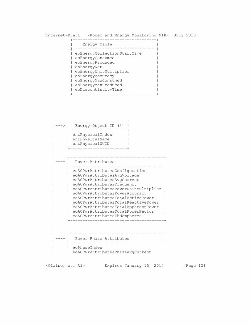
Internet-Draft <Power and Energy Monitoring MIB> July 2013 +----------------------------------+ | Energy Table | | -------------------------------- | | eoEnergyCollectionStartTime | | eoEnergyConsumed | | eoEnergyProduced | | eoEnergyNet | | eoEnergyUnitMultiplier | | eoEnergyAccuracy | | eoEnergyMaxConsumed | | eoEnergyMaxProduced | | eoDiscontinuityTime | +----------------------------------+
+-----------------------+ |---> | Energy Object ID (*) | | | --------------------- | | | entPhysicalIndex | | | entPhysicalName | | | entPhysicalUUID | | +-----------------------+ | | +--------------------------------------+ |---- | Power Attributes | | | ------------------------------------ | | | eoACPwrAttributesConfiguration | | | eoACPwrAttributesAvgVoltage | | | eoACPwrAttributesAvgCurrent | | | eoACPwrAttributesFrequency | | | eoACPwrAttributesPowerUnitMultiplier | | | eoACPwrAttributesPowerAccuracy | | | eoACPwrAttributesTotalActivePower | | | eoACPwrAttributesTotalReactivePower | | | eoACPwrAttributesTotalApparentPower | | | eoACPwrAttributesTotalPowerFactor | | | eoACPwrAttributesThdAmpheres | | +--------------------------------------+ | | | +--------------------------------------+ |---- | Power Phase Attributes | | | ------------------------------------ | | | eoPhaseIndex | | | eoACPwrAttributesPhaseAvgCurrent |
<Claise, et. Al> Expires January 15, 2014 [Page 12]

Internet-Draft <Power and Energy Monitoring MIB> July 2013 | | eoACPwrAttributesPhaseActivePower | | | eoACPwrAttributesPhaseReactivePower | | | eoACPwrAttributesPhaseApparentPower | | | eoACPwrAttributesPhasePowerFactor | | | eoACPwrAttributesPhaseImpedance | | +--------------------------------------+ | | | +------------------------------------------------+ |---- | AC Input DEL Configuration | | | ---------------------------------------------- | | | eoACPwrAttributesDelPhaseToNextPhaseVoltage | | | eoACPwrAttributesDelThdPhaseToNextPhaseVoltage | | | eoACPwrAttributesDelThdCurrent | | +------------------------------------------------+ | | +----------------------------------------------+ |---- | AC Input WYE Configuration | | -------------------------------------------- | | eoACPwrAttributesWyePhaseToNeutralVoltage | | eoACPwrAttributesWyePhaseCurrent | | eoACPwrAttributesWyeThdPhaseToNeutralVoltage | +----------------------------------------------+
Figure 2: UML diagram for the powerAttributesMIB
(*) Compliance with the ENERGY-AWARE-MIB
5.1. Energy Object Information
Refer to the "Energy Object Information" section in [EMAN-FMWK] for background information. An energy aware device is considered as an instance of a Energy Object as defined in the [EMAN-FMWK].
The Energy Object identity information is specified in the MIB ENERGY-AWARE-MIB module [EMAN-AWARE-MIB] primary table, i.e. the eoTable. In this table, the context of the Energy Object such as Domain, RoleDescription, Importance are specified. In addition, the ENERGY-AWARE-MIB module returns the relationship between Objects. There are several possible relationships between Parent and Child as defined in [EMAN-AWARE-MIB] such as MeteredBy, PoweredBy, and AggregatedBy.
<Claise, et. Al> Expires January 15, 2014 [Page 13]

Internet-Draft <Power and Energy Monitoring MIB> July 2013 5.2. Power State
Refer to the "Power States" section in [EMAN-FMWK] for background information.
An Energy Object may have energy conservation modes called Power States. Between the ON and OFF states of a device, there can be several intermediate energy saving modes. Those energy saving modes are called as Power States.
Power States, which represent universal states of power management of an Energy Object, are specified by the eoPowerState MIB object. The actual Power State is specified by the eoPowerOperState MIB object, while the eoPowerAdminState MIB object specifies the Power State requested for the Energy Object. The difference between the values of eoPowerOperState and eoPowerAdminState can be attributed that the Energy Object is busy transitioning from eoPowerAdminState into the eoPowerOperState, at which point it will update the content of eoPowerOperState. In addition, the possible reason for change in Power State is reported in eoPowerStateEnterReason. Regarding eoPowerStateEnterReason, management stations and Energy Objects should support any format of the owner string dictated by the local policy of the organization. It is suggested that this name contain at least the reason for the transition change, and one or more of the following: IP address, management station name, network manager’s name, location, or phone number.
The MIB objects eoPowerOperState, eoPowerAdminState , and eoPowerStateEnterReason are contained in the eoPowerTable MIB table.
The eoPowerStateTable table enumerates the maximum power usage in watts, for every single supported Power State of each Power State Set supported by the Energy Object. In addition, PowerStateTable provides additional statistics: eoPowerStateEnterCount, the number of times an entity has visited a particular Power State, and eoPowerStateTotalTime, the total time spent in a particular Power State of an Energy Object.
5.2.1. Power State Set
There are several standards and implementations of Power State Sets. A Energy Object can support one or multiple Power State Set implementation(s) concurrently.
<Claise, et. Al> Expires January 15, 2014 [Page 14]

Internet-Draft <Power and Energy Monitoring MIB> July 2013 There are currently three Power State Sets advocated:
unknown(0) IEEE1621(256) - [IEEE1621] DMTF(512) - [DMTF] EMAN(1024) - [EMAN-MONITORING-MIB]
The respective specific states related to each Power State Set are specified in the following sections. The guidelines for addition of new Power State Sets have been specified in the IANA Considerations Section.
The Power States within each Power State Set are listed in [EMAN-FMWK]. The Textual Convention IANAPowerStateSet provides the proposed numbering of the Power States within the IEEE1621 Power State Set, DMTF Power State Set and the EMAN Power State Set.
5.3. Energy Object Usage Information
Refer to the "Energy Object Usage Measurement" section in [EMAN- FMWK] for background information.
For an Energy Object, power usage is reported using eoPower. The magnitude of measurement is based on the eoPowerUnitMultiplier MIB variable, based on the UnitMultiplier Textual Convention (TC). Power measurement magnitude should conform to the IEC 62053-21 [IEC.62053-21] and IEC 62053-22 [IEC.62053-22] definition of unit multiplier for the SI (System International) units of measure. Measured values are represented in SI units obtained by BaseValue * 10 raised to the power of the scale.
For example, if current power usage of an Energy Object is 3, it could be 3 W, 3 mW, 3 KW, or 3 MW, depending on the value of eoPowerUnitMultiplier. Note that other measurements throughout the two MIB modules in this document use the same mechanism, including eoPowerStatePowerUnitMultiplier, eoEnergyUnitMultiplier, and eoACPwrAttributesPowerUnitMultiplier.
In addition to knowing the usage and magnitude, it is useful to know how a eoPower measurement was obtained. An NMS can use this to account for the accuracy and nature of the reading between different implementations. For this eoPowerOrigin describes whether the measurements were made at the device itself or from a remote source. The eoPowerMeasurementCaliber
<Claise, et. Al> Expires January 15, 2014 [Page 15]

Internet-Draft <Power and Energy Monitoring MIB> July 2013 describes the method that was used to measure the power and can distinguish actual or estimated values. There may be devices in the network, which may not be able to measure or report power consumption. For those devices, the object eoPowerMeasurementCaliber shall report that measurement mechanism is "unavailable" and the eoPower measurement shall be "0".
The nameplate power rating of an Energy Object is specified in eoPowerNameplate MIB object.
5.4. Optional Power Usage Attributes
Refer to the "Optional Power Usage Attributes" section in [EMAN-FMWK] for background information.
The optional powerAttributesMIB MIB module can be implemented to further describe power usage attributes measurement. The powerAttributesMIB MIB module adheres closely to the IEC 61850 7-2 standard to describe AC measurements.
The powerAttributesMIB MIB module contains a primary table, the eoACPwrAttributesTable table, that defines power attributes measurements for supported entPhysicalIndex entities, as a sparse extension of the eoPowerTable (with entPhysicalIndex as primary index). This eoACPwrAttributesTable table contains such information as the configuration (single phase, DEL 3 phases, WYE 3 phases), voltage, frequency, power accuracy, total active/reactive power/apparent power, amperage, and voltage.
In case of 3-phase power, the eoACPwrAttributesPhaseTable additional table is populated with Power Attributes measurements per phase (so double indexed by the entPhysicalIndex and eoPhaseIndex). This table, which describes attributes common to both WYE and DEL configurations, contains the average current, active/reactive/apparent power, power factor, and impedance.
In case of 3-phase power with a DEL configuration, the eoACPwrAttributesDelPhaseTable table describes the phase-to- phase power attributes measurements, i.e., voltage and current.
In case of 3-phase power with a Wye configuration, the eoACPwrAttributesWyePhaseTable table describes the phase-to- neutral power attributes measurements, i.e., voltage and current.
<Claise, et. Al> Expires January 15, 2014 [Page 16]

Internet-Draft <Power and Energy Monitoring MIB> July 2013 5.5. Optional Energy Measurement
Refer to the "Optional Energy and demand Measurement" section in [EMAN-FMWK] for the definition and terminology information.
It is relevant to measure energy and demand only when there are actual power measurements obtained from measurement hardware. If the eoPowerMeasurementCaliber MIB object has values of unavailable, unknown, estimated, or presumed, then the energy and demand values are not useful.
Two tables are introduced to characterize energy measurement of an Energy Object: eoEnergyTable and eoEnergyParametersTable. Both energy and demand information can be represented via the eoEnergyTable. Energy information will be an accumulation with no interval. Demand information can be represented. The eoEnergyParametersTable consists of the parameters defining eoEnergyParametersIndex an index of that specifies the setting for collection of energy measurements for an Energy Object, eoEnergyObjectIndex linked to the entPhysicalIndex of the Energy Object, the duration of measurement intervals in seconds, (eoEnergyParametersIntervalLength), the number of successive intervals to be stored in the eoEnergyTable, (eoEnergyParametersIntervalNumber), the type of measurement technique (eoEnergyParametersIntervalMode), and a sample rate used to calculate the average (eoEnergyParametersSampleRate). Judicious choice of the sampling rate will ensure accurate measurement of energy while not imposing an excessive polling burden.
There are three eoEnergyParametersIntervalMode types used for energy measurement collection: period, sliding, and total. The choices of the the three different modes of collection are based on IEC standard 61850-7-4. Note that multiple eoEnergyParametersIntervalMode types MAY be configured simultaneously. It is important to note that for a given Energy Object, multiple modes (periodic, total, sliding window) of energy measurement collection can be configured with the use of eoEnergyParametersIndex. However, simultaneous measurement in multiple modes for a given Energy Object depends on the Energy Object capability.
These three eoEnergyParametersIntervalMode types are illustrated by the following three figures, for which:
- The horizontal axis represents the current time, with the symbol <--- L ---> expressing the
<Claise, et. Al> Expires January 15, 2014 [Page 17]

Internet-Draft <Power and Energy Monitoring MIB> July 2013 eoEnergyParametersIntervalLength, and the eoEnergyCollectionStartTime is represented by S1, S2, S3, S4, ..., Sx where x is the value of eoEnergyParametersIntervalNumber.
- The vertical axis represents the time interval of sampling and the value of eoEnergyConsumed can be obtained at the end of the sampling period. The symbol =========== denotes the duration of the sampling period.
| | | =========== | |============ | | | | | | | | |============ | | | | | | | <--- L ---> | <--- L ---> | <--- L ---> | | | | | S1 S2 S3 S4
Figure 4 : Period eoEnergyParametersIntervalMode
A eoEnergyParametersIntervalMode type of ’period’ specifies non- overlapping periodic measurements. Therefore, the next eoEnergyCollectionStartTime is equal to the previous eoEnergyCollectionStartTime plus eoEnergyParametersIntervalLength. S2=S1+L; S3=S2+L, ...
|============ | | | | <--- L ---> | | | | |============ | | | | | | <--- L ---> | | | | | | |============ | | | | | | | | <--- L ---> | | | | | | | | |============ | | | | | | | | | | <--- L ---> | S1 | | | | | | | | | | | | S2 | | |
<Claise, et. Al> Expires January 15, 2014 [Page 18]

Internet-Draft <Power and Energy Monitoring MIB> July 2013 | | | | | | S3 | | | | | | S4
Figure 5 : Sliding eoEnergyParametersIntervalMode
A eoEnergyParametersIntervalMode type of ’sliding’ specifies overlapping periodic measurements.
| | |========================= | | | | | | | | <--- Total length ---> | | | S1
Figure 6 : Total eoEnergyParametersIntervalMode
A eoEnergyParametersIntervalMode type of ’total’ specifies a continuous measurement since the last reset. The value of eoEnergyParametersIntervalNumber should be (1) one and eoEnergyParametersIntervalLength is ignored.
The eoEnergyParametersStatus is used to start and stop energy usage logging. The status of this variable is "active" when all the objects in eoEnergyParametersTable are appropriate which in turn indicates if eoEnergyTable entries exist or not.
The eoEnergyTable consists of energy measurements in eoEnergyConsumed, eoEnergyProduced and eoEnergyNet, the units of the measured energy eoEnergyUnitMultiplier, and the maximum observed energy within a window eoEnergyMaxConsumed, eoEnergyMaxProduced.
Measurements of the total energy consumed by an Energy Object may suffer from interruptions in the continuous measurement of energy consumption. In order to indicate such interruptions, the object eoEnergyDiscontinuityTime is provided for indicating the time of the last interruption of total energy measurement. eoEnergyDiscontinuityTime shall indicate the sysUpTime [RFC3418] when the device was reset.
<Claise, et. Al> Expires January 15, 2014 [Page 19]

Internet-Draft <Power and Energy Monitoring MIB> July 2013 The following example illustrates the eoEnergyTable and eoEnergyParametersTable:
First, in order to estimate energy, a time interval to sample energy should be specified, i.e. eoEnergyParametersIntervalLength can be set to "900 seconds" or 15 minutes and the number of consecutive intervals over which the maximum energy is calculated (eoEnergyParametersIntervalNumber) as "10". The sampling rate internal to the Energy Object for measurement of power usage (eoEnergyParametersSampleRate) can be "1000 milliseconds", as set by the Energy Object as a reasonable value. Then, the eoEnergyParametersStatus is set to active (value 1) to indicate that the Energy Object should start monitoring the usage per the eoEnergyTable.
The indices for the eoEnergyTable are eoEnergyParametersIndex which identifies the index for the setting of energy measurement collection Energy Object, and eoEnergyCollectionStartTime, which denotes the start time of the energy measurement interval based on sysUpTime [RFC3418]. The value of eoEnergyComsumed is the measured energy consumption over the time interval specified (eoEnergyParametersIntervalLength) based on the Energy Object internal sampling rate (eoEnergyParametersSampleRate). While choosing the values for the eoEnergyParametersIntervalLength and eoEnergyParametersSampleRate, it is recommended to take into consideration either the network element resources adequate to process and store the sample values, and the mechanism used to calculate the eoEnergyConsumed. The units are derived from eoEnergyUnitMultiplier. For example, eoEnergyConsumed can be "100" with eoEnergyUnitMultiplier equal to 0, the measured energy consumption of the Energy Object is 100 watt-hours. The eoEnergyMaxConsumed is the maximum energy observed and that can be "150 watt-hours".
The eoEnergyTable has a buffer to retain a certain number of intervals, as defined by eoEnergyParametersIntervalNumber. If the default value of "10" is kept, then the eoEnergyTable contains 10 energy measurements, including the maximum.
Here is a brief explanation of how the maximum energy can be calculated. The first observed energy measurement value is taken to be the initial maximum. With each subsequent measurement, based on numerical comparison, maximum energy may be updated. The maximum value is retained as long as the measurements are taking place. Based on periodic polling of
<Claise, et. Al> Expires January 15, 2014 [Page 20]

Internet-Draft <Power and Energy Monitoring MIB> July 2013 this table, an NMS could compute the maximum over a longer period, i.e. a month, 3 months, or a year.
5.6. Fault Management
[EMAN-REQ] specifies requirements about Power States such as "the current power state" , "the time of the last state change", "the total time spent in each state", "the number of transitions to each state" etc. Some of these requirements are fulfilled explicitly by MIB objects such as eoPowerOperState, eoPowerStateTotalTime and eoPowerStateEnterCount. Some of the other requirements are met via the SNMP NOTIFICATION mechanism. eoPowerStateChange SNMP notification which is generated when the value(s) of ,eoPowerStateIndex, eoPowerOperState, eoPowerAdminState have changed.
6. Discovery
It is foreseen that most Energy Objects will require the implementation of the ENERGY-AWARE MIB [EMAN-AWARE-MIB] as a prerequisite for this MIB module. In such a case, eoPowerTable of the EMAN-MON-MIB is a sparse extension of the eoTable of ENERGY-AWARE-MIB. Every Energy Object MUST implement entPhysicalIndex, entPhysicalUUID and entPhysicalName from the ENTITY-MIB [RFC6933]. As the primary index for the Energy Object, entPhysicalIndex is used.
The NMS must first poll the ENERGY-AWARE-MIB module [EMAN-AWARE- MIB], if available, in order to discover all the Energy Objects and the relationships between those (notion of Parent/Child). In the ENERGY-AWARE-MIB module tables, the Energy Objects are indexed by the entPhysicalIndex.
If an implementation of the ENERGY-AWARE-MIB module is available in the local SNMP context, for the same Energy Object, the entPhysicalIndex value (EMAN-AWARE-MIB) shall be used. The entPhysicalIndex characterizes the Energy Object in the energyObjectMib and the powerAttributesMIB MIB modules (this document).
From there, the NMS must poll the eoPowerStateTable (specified in the energyObjectMib module in this document), which enumerates, amongst other things, the maximum power usage. As the entries in eoPowerStateTable table are indexed by the Energy Object ( entPhysicalIndex), by the Power State Set (eoPowerStateIndex), the maximum power usage is discovered per
<Claise, et. Al> Expires January 15, 2014 [Page 21]

Internet-Draft <Power and Energy Monitoring MIB> July 2013 Energy Object, and the power usage per Power State of the Power State Set. In other words, polling the eoPowerStateTable allows the discovery of each Power State within every Power State Set supported by the Energy Object.
If the Energy Object is an Aggregator or a Proxy, the MIB module would be populated with the Energy Object Parent and Children information, which have their own Energy Object index value (entPhysicalIndex). However, the parent/child relationship must be discovered thanks to the ENERGY-AWARE-MIB module.
Finally, the NMS can monitor the power attributes thanks to the powerAttributesMIB MIB module, which reuses the entPhysicalIndex to index the Energy Object.
7. Link with the other IETF MIBs
7.1. Link with the ENTITY-MIB and the ENTITY-SENSOR MIB
RFC 4133 [RFC4133] defines the ENTITY-MIB module that lists the physical entities of a networking device (router, switch, etc.) and those physical entities indexed by entPhysicalIndex. From an energy-management standpoint, the physical entities that consume or produce energy are of interest.
RFC 3433 [RFC3433] defines the ENTITY-SENSOR MIB module that provides a standardized way of obtaining information (current value of the sensor, operational status of the sensor, and the data units precision) from sensors embedded in networking devices. Sensors are associated with each index of entPhysicalIndex of the ENTITY-MIB [RFC4133]. While the focus of the Power and Energy Monitoring MIB is on measurement of power usage of networking equipment indexed by the ENTITY-MIB, this MIB proposes a customized power scale for power measurement and different power state states of networking equipment, and functionality to configure the power state states.
When this MIB module is used to monitor the power usage of devices like routers and switches, the ENTITY-MIB and ENTITY- SENSOR MIB SHOULD be implemented. In such cases, the Energy Objects are modeled by the entPhysicalIndex through the entPhysicalEntity MIB object specified in the eoTable in the ENERGY-AWARE-MIB MIB module [EMAN-AWARE-MIB].
However, the ENTITY-SENSOR MIB [RFC3433] does not have the ANSI C12.x accuracy classes required for electricity (i.e., 1%, 2%,
<Claise, et. Al> Expires January 15, 2014 [Page 22]

Internet-Draft <Power and Energy Monitoring MIB> July 2013 0.5% accuracy classes). Indeed, entPhySensorPrecision [RFC3433] represents "The number of decimal places of precision in fixed- point sensor values returned by the associated entPhySensorValue object". The ANSI and IEC Standards are used for power measurement and these standards require that we use an accuracy class, not the scientific-number precision model specified in RFC3433. The eoPowerAccuracy MIB object models this accuracy. Note that eoPowerUnitMultipler represents the scale factor per IEC 62053-21 [IEC.62053-21] and IEC 62053-22 [IEC.62053-22], which is a more logical representation for power measurements (compared to entPhySensorScale), with the mantissa and the exponent values X * 10 ^ Y.
Power measurements specifying the qualifier ’UNITS’ for each measured value in watts are used in the LLDP-EXT-MED-MIB, POE [RFC3621], and UPS [RFC1628] MIBs. The same ’UNITS’ qualifier is used for the power measurement values.
One cannot assume that the ENTITY-MIB and ENTITY-SENSOR MIB are implemented for all Energy Objects that need to be monitored. A typical example is a converged building gateway, monitoring several other devices in the building, doing the proxy between SNMP and a protocol like BACNET. Another example is the home energy controller. In such cases, the eoPhysicalEntity value contains the zero value, thanks to PhysicalIndexOrZero textual convention.
The eoPower is similar to entPhySensorValue [RFC3433] and the eoPowerUnitMultipler is similar to entPhySensorScale.
7.2. Link with the ENTITY-STATE MIB
For each entity in the ENTITY-MIB [RFC4133], the ENTITY-STATE MIB [RFC4268] specifies the operational states (entStateOper: unknown, enabled, disabled, testing), the alarm (entStateAlarm: unknown, underRepair, critical, major, minor, warning, indeterminate) and the possible values of standby states (entStateStandby: unknown, hotStandby, coldStandby, providingService).
From a power monitoring point of view, in contrast to the entity operational states of entities, Power States are required, as proposed in the Power and Energy Monitoring MIB module. Those Power States can be mapped to the different operational states in the ENTITY-STATE MIB, if a formal mapping is required. For example, the entStateStandby "unknown", "hotStandby", "coldStandby", states could map to the Power State "unknown",
<Claise, et. Al> Expires January 15, 2014 [Page 23]

Internet-Draft <Power and Energy Monitoring MIB> July 2013 "ready", "standby", respectively, while the entStateStandby "providingService" could map to any "low" to "high" Power State.
7.3. Link with the POWER-OVER-ETHERNET MIB
Power-over-Ethernet MIB [RFC3621] provides an energy monitoring and configuration framework for power over Ethernet devices. The RFC introduces a concept of a port group on a switch to define power monitoring and management policy and does not use the entPhysicalIndex as the index. Indeed, the pethMainPseConsumptionPower is indexed by the pethMainPseGroupIndex, which has no mapping with the entPhysicalIndex.
One cannot assume that the Power-over-Ethernet MIB is implemented for all Energy Objects that need to be monitored. A typical example is a converged building gateway, monitoring several other devices in the building, doing the proxy between SNMP and a protocol like BACNET. Another example is the home energy controller. In such cases, the eoethPortIndex and eoethPortGrpIndex values contain the zero value, thanks to new PethPsePortIndexOrZero and textual PethPsePortGroupIndexOrZero conventions.
However, if the Power-over-Ethernet MIB [RFC3621] is supported, the Energy Object eoethPortIndex and eoethPortGrpIndex contain the pethPsePortIndex and pethPsePortGroupIndex, respectively.
As a consequence, the entPhysicalIndex MIB object has been kept as the unique Energy Object index.
Note that, even though the Power-over-Ethernet MIB [RFC3621] was created after the ENTITY-SENSOR MIB [RFC3433], it does not reuse the precision notion from the ENTITY-SENSOR MIB, i.e. the entPhySensorPrecision MIB object.
7.4. Link with the UPS MIB
To protect against unexpected power disruption, data centers and buildings make use of Uninterruptible Power Supplies (UPS). To protect critical assets, a UPS can be restricted to a particular subset or domain of the network. UPS usage typically lasts only for a finite period of time, until normal power supply is restored. Planning is required to decide on the capacity of the UPS based on output power and duration of probable power outage. To properly provision UPS power in a data center or building, it
<Claise, et. Al> Expires January 15, 2014 [Page 24]

Internet-Draft <Power and Energy Monitoring MIB> July 2013 is important to first understand the total demand required to support all the entities in the site. This demand can be assessed and monitored via the Power and Energy Monitoring MIB.
UPS MIB [RFC1628] provides information on the state of the UPS network. Implementation of the UPS MIB is useful at the aggregate level of a data center or a building. The MIB module contains several groups of variables:
- upsIdent: Identifies the UPS entity (name, model, etc.).
- upsBattery group: Indicates the battery state (upsbatteryStatus, upsEstimatedMinutesRemaining, etc.)
- upsInput group: Characterizes the input load to the UPS (number of input lines, voltage, current, etc.).
- upsOutput: Characterizes the output from the UPS (number of output lines, voltage, current, etc.)
- upsAlarms: Indicates the various alarm events.
The measurement of power in the UPS MIB is in Volts, Amperes and Watts. The units of power measurement are RMS volts and RMS Amperes. They are not based on the EntitySensorDataScale and EntitySensorDataPrecision of ENTITY-SENSOR-MIB.
Both the Power and Energy Monitoring MIB and the UPS MIB may be implemented on the same UPS SNMP agent, without conflict. In this case, the UPS device itself is the Energy Object Parent and any of the UPS meters or submeters are the Energy Object Children.
7.5. Link with the LLDP and LLDP-MED MIBs
The LLDP Protocol is a Data Link Layer protocol used by network devices to advertise their identities, capabilities, and interconnections on a LAN network.
The Media Endpoint Discovery is an enhancement of LLDP, known as LLDP-MED. The LLDP-MED enhancements specifically address voice applications. LLDP-MED covers 6 basic areas: capability discovery, LAN speed and duplex discovery, network policy discovery, location identification discovery, inventory discovery, and power discovery.
<Claise, et. Al> Expires January 15, 2014 [Page 25]

Internet-Draft <Power and Energy Monitoring MIB> July 2013 Of particular interest to the current MIB module is the power discovery, which allows the endpoint device (such as a PoE phone) to convey power requirements to the switch. In power discovery, LLDP-MED has four Type Length Values (TLVs): power type, power source, power priority and power value. Respectively, those TLVs provide information related to the type of power (power sourcing entity versus powered device), how the device is powered (from the line, from a backup source, from external power source, etc.), the power priority (how important is it that this device has power?), and how much power the device needs.
The power priority specified in the LLDP-MED MIB [LLDP-MED-MIB] actually comes from the Power-over-Ethernet MIB [RFC3621]. If the Power-over-Ethernet MIB [RFC3621] is supported, the exact value from the pethPsePortPowerPriority [RFC3621] is copied over in the lldpXMedRemXPoEPDPowerPriority [LLDP-MED-MIB]; otherwise the value in lldpXMedRemXPoEPDPowerPriority is "unknown". From the Power and Energy Monitoring MIB, it is possible to identify the pethPsePortPowerPriority [RFC3621], thanks to the eoethPortIndex and eoethPortGrpIndex.
The lldpXMedLocXPoEPDPowerSource [LLDP-MED-MIB] is similar to eoPowerOrigin in indicating if the power for an attached device is local or from a remote device. If the LLDP-MED MIB is supported, the following mapping can be applied to the eoPowerOrigin: lldpXMedLocXPoEPDPowerSource fromPSE(2) and local(3) can be mapped to remote(2) and self(1), respectively.
8. Implementation Scenario
This section provides an illustrative example scenario for the implementation of the Energy Object, including Energy Object Parent and Energy Object Child relationships.
Example Scenario of a campus network: Switch with PoE Endpoints with further connected devices.
The campus network consists of switches that provide LAN connectivity. The switch with PoE ports is located in wiring closet. PoE IP phones are connected to the switch. The IP phones draw power from the PoE ports of the switch. In addition, a PC is daisy-chained from the IP phone for LAN connectivity.
<Claise, et. Al> Expires January 15, 2014 [Page 26]

Internet-Draft <Power and Energy Monitoring MIB> July 2013 The IP phone consumes power from the PoE switch, while the PC consumes power from the wall outlet.
The switch has implementations of ENTITY-MIB [RFC6933] and ENERGY-AWARE MIB [EMAN-AWARE-MIB] while the PC does not have implementation of the ENTITY-MIB, but has an implementation of ENERGY-AWARE MIB [EMAN-AWARE-MIB]. The switch has the following attributes, entPhysicalIndex "1", and entPhysicalUUID "UUID 1000". The power usage of the switch is "440 Watts". The switch does not have an Energy Object Parent.
The PoE switch port has the following attributes: The switch port has entPhysicalIndex "3", and entPhysicalUUID is "UUID 1000:3". The power metered at the POE switch port is "12 watts". In this example, the POE switch port has the switch as the Energy Object Parent, with its eoParentID of "1000".
The attributes of the PC are given below. The PC does not have an entPhysicalIndex, and the entPhysicalUUID is "UUID 1000:57 ". The PC has an Energy Object Parent, i.e. the switch port whose entPhysicalUUID is "UUID 1000:3". The power usage of the PC is "120 Watts" and is communicated to the switch port.
This example illustrates the important distinction between the Energy Object Children: The IP phone draws power from the switch, while the PC has LAN connectivity from the phone, but is powered from the wall outlet. However, the Energy Object Parent sends power control messages to both the Energy Object Children (IP phone and PC) and the Children react to those messages.
|-------------------------------------------------------| | Switch | |=======================================================| | Switch | Switch | Switch | Switch | | entPhyIndx | UUID |eoParentId | eoPower | | ===================================================== | | 1 | UUID 1000 | null | 440 | | ===================================================== | | | | SWITCH PORT | | ===================================================== | | | Switch | Switch | Switch | Switch | | | Port | Port | Port | Port | | | entPhyIndx | UUID | eoParentId | eoPower | | ===================================================== |
<Claise, et. Al> Expires January 15, 2014 [Page 27]

Internet-Draft <Power and Energy Monitoring MIB> July 2013 | | 3 | UUID 1000:3 | 1000 | 12 | | ======================================================| | ^ | | |-----------------------------------|------------------- | | POE IP PHONE | | | ====================================================== | IP phone | IP phone | IP phone | IP phone | | entPhyIndx | UUID | eoParentID | eoPower | ====================================================== | Null | UUID 1000:31| UUID 1000:3 | 12 | ======================================================= | | PC connected to switch via IP phone | | ===================================================== | PC | PC | PC | PC | |entPhyIndx | UUID | eoParentID | eoPower | ===================================================== | 7 | UUID 1000:57| UUID 1000:3 | 120 | =====================================================
Figure 1: Example scenario
9. Structure of the MIB
The primary MIB object in this MIB module is the energyObjectMibObject. The eoPowerTable table of energyObjectMibObject describes the power measurement attributes of an Energy Object entity. The notion of identity of the device in terms of uniquely identification of the Energy Object and its relationship to other entities in the network are addressed in [EMAN-AWARE-MIB].
Logically, this MIB module is a sparse extension of the [EMAN-AWARE-MIB] module. Thus the following requirements which are applied to [EMAN-AWARE-MIB] are also applicable. As a requirement for this MIB module, [EMAN-AWARE-MIB] should be implemented and as Module Compliance of ENTITY-MIB V4 [RFC6933] with respect to entity4CRCompliance should be supported which
<Claise, et. Al> Expires January 15, 2014 [Page 28]

Internet-Draft <Power and Energy Monitoring MIB> July 2013 requires 3 MIB objects (entPhysicalIndex, entPhysicalName and entPhysicalUUID ) MUST be implemented.
eoMeterCapabilitiesTable is useful to enable applications to determine the capabilities supported by the local management agent. This table indicates the energy monitoring MIB groups that are supported by the local management system. By reading the value of this object, it is possible for applications to know which tables contain the information and are usable without walking through the table and querying every element which involves a trial-and-error process.
The power measurement of an Energy Object contains information describing its power usage (eoPower) and its current power state (eoPowerOperState). In addition to power usage, additional information describing the units of measurement (eoPowerAccuracy, eoPowerUnitMultiplier), how power usage measurement was obtained (eoPowerMeasurementCaliber), the source of power (eoPowerOrigin) and the type of power (eoPowerCurrentTtype) are described.
An Energy Object may contain an optional eoPowerAttributes table that describes the electrical characteristics associated with the current power state and usage.
An Energy Object may contain an optional eoEnergyTable to describe energy measurement information over time.
An Energy Object may also contain optional battery information associated with this entity.
10. MIB Definitions
-- ************************************************************ -- -- -- This MIB is used to monitor power usage of network -- devices -- -- *************************************************************
ENERGY-OBJECT-MIB DEFINITIONS ::= BEGIN
<Claise, et. Al> Expires January 15, 2014 [Page 29]

Internet-Draft <Power and Energy Monitoring MIB> July 2013 IMPORTS MODULE-IDENTITY, OBJECT-TYPE, NOTIFICATION-TYPE, mib-2, Integer32, Counter32, TimeTicks FROM SNMPv2-SMI TEXTUAL-CONVENTION, DisplayString, RowStatus, TimeInterval, TimeStamp, TruthValue FROM SNMPv2-TC MODULE-COMPLIANCE, NOTIFICATION-GROUP, OBJECT-GROUP FROM SNMPv2-CONF OwnerString FROM RMON-MIB entPhysicalIndex, PhysicalIndex FROM ENTITY-MIB;
energyObjectMib MODULE-IDENTITY LAST-UPDATED "201306300000Z" -- 30 June 2013
ORGANIZATION "IETF EMAN Working Group" CONTACT-INFO "WG charter: http://datatracker.ietf.org/wg/eman/charter/
Mailing Lists: General Discussion: [email protected]
To Subscribe: https://www.ietf.org/mailman/listinfo/eman
Archive: http://www.ietf.org/mail-archive/web/eman
Editors: Mouli Chandramouli Cisco Systems, Inc. Sarjapur Outer Ring Road Bangalore 560103 IN Phone: +91 80 4429 2409 Email: [email protected]
Brad Schoening 44 Rivers Edge Drive Little Silver, NJ 07739
<Claise, et. Al> Expires January 15, 2014 [Page 30]

Internet-Draft <Power and Energy Monitoring MIB> July 2013 US Email: [email protected]
Juergen Quittek NEC Europe Ltd. NEC Laboratories Europe Network Research Division Kurfuersten-Anlage 36 Heidelberg 69115 DE Phone: +49 6221 4342-115 Email: [email protected]
Thomas Dietz NEC Europe Ltd. NEC Laboratories Europe Network Research Division Kurfuersten-Anlage 36 69115 Heidelberg DE Phone: +49 6221 4342-128 Email: [email protected]
Benoit Claise Cisco Systems, Inc. De Kleetlaan 6a b1 Degem 1831 Belgium Phone: +32 2 704 5622 Email: [email protected]"
DESCRIPTION "This MIB is used to monitor power and energy in devices.
This table sparse extension of the eoTable from the ENERGY-AWARE-MIB. As a requirement [EMAN-AWARE-MIB] should be implemented.
Module Compliance of ENTITY-MIB v4 with respect to entity4CRCompliance should be supported which requires implementation of 3 MIB objects (entPhysicalIndex, entPhysicalName and entPhysicalUUID)."
REVISION "201306300000Z" -- 30 June 2013
<Claise, et. Al> Expires January 15, 2014 [Page 31]

Internet-Draft <Power and Energy Monitoring MIB> July 2013 DESCRIPTION "Initial version, published as RFC XXXX."
::= { mib-2 xxx }
energyObjectMibNotifs OBJECT IDENTIFIER ::= { energyObjectMib 0 }
energyObjectMibObjects OBJECT IDENTIFIER ::= { energyObjectMib 1 }
energyObjectMibConform OBJECT IDENTIFIER ::= { energyObjectMib 2 }
-- Textual Conventions
IANAPowerStateSet ::= TEXTUAL-CONVENTION STATUS current DESCRIPTION
"IANAPowerState is a textual convention that describes Power State Sets and Power State Set Values an Energy Object supports. IANA has created a registry of Power State supported by an Energy Object and IANA shall administer the list of Power State Sets and Power States.
The textual convention assumes that power states in a power state set are limited to 255 distinct values. For a Power State Set S, the named number with the value S * 256 is allocated to indicate the power state set. For a Power State X in the Power State S, the named number with the value S * 256 + X + 1 is allocated to represent the power state."
REFERENCE "http://www.iana.org/assignments/eman RFC EDITOR NOTE: please change the previous URL if this is not the correct one after IANA assigned it."
SYNTAX INTEGER { other(0), -- indicates other set unknown(255), -- unknown power state
<Claise, et. Al> Expires January 15, 2014 [Page 32]

Internet-Draft <Power and Energy Monitoring MIB> July 2013 ieee1621(256), -- indicates IEEE1621 set ieee1621On(257), ieee1621Off(258), ieee1621Sleep(259),
dmtf(512), -- indicates DMTF set dmtfOn(513), dmtfSleepLight(514), dmtfSleepDeep(515), dmtfOffHard(516), dmtfOffSoft(517), dmtfHibernate(518), dmtfPowerOffSoft(519), dmtfPowerOffHard(520), dmtfMasterBusReset(521), dmtfDiagnosticInterrapt(522), dmtfOffSoftGraceful(523), dmtfOffHardGraceful(524), dmtfMasterBusResetGraceful(525), dmtfPowerCycleOffSoftGraceful(526), dmtfPowerCycleHardGraceful(527),
eman(1024), -- indicates EMAN set emanmechoff(1025), emansoftoff(1026), emanhibernate(1027), emansleep(1028), emanstandby(1029), emanready(1030), emanlowMinus(1031), emanlow(1032), emanmediumMinus(1033), emanmedium(1034), emanhighMinus(1035), emanhigh(1036) }
UnitMultiplier ::= TEXTUAL-CONVENTION STATUS current DESCRIPTION "The Unit Multiplier is an integer value that represents the IEEE 61850 Annex A units multiplier associated with the integer units used to measure the power or energy.
For example, when used with eoPowerUnitMultiplier, -3 represents 10^-3 or milliwatts." REFERENCE "The International System of Units (SI),
<Claise, et. Al> Expires January 15, 2014 [Page 33]

Internet-Draft <Power and Energy Monitoring MIB> July 2013 National Institute of Standards and Technology, Spec. Publ. 330, August 1991." SYNTAX INTEGER { yocto(-24), -- 10^-24 zepto(-21), -- 10^-21 atto(-18), -- 10^-18 femto(-15), -- 10^-15 pico(-12), -- 10^-12 nano(-9), -- 10^-9 micro(-6), -- 10^-6 milli(-3), -- 10^-3 units(0), -- 10^0 kilo(3), -- 10^3 mega(6), -- 10^6 giga(9), -- 10^9 tera(12), -- 10^12 peta(15), -- 10^15 exa(18), -- 10^18 zetta(21), -- 10^21 yotta(24) -- 10^24 }
-- Objects
eoMeterCapabilitiesTable OBJECT-TYPE SYNTAX SEQUENCE OF EoMeterCapabilitiesEntry MAX-ACCESS not-accessible STATUS current DESCRIPTION "This table is useful for helping applications determine the monitoring capabilities supported by the local management agents. It is possible for applications to know which tables are usable without going through a trial-and-error process." ::= { energyObjectMibObjects 1 }
eoMeterCapabilitiesEntry OBJECT-TYPE SYNTAX EoMeterCapabilitiesEntry MAX-ACCESS not-accessible STATUS current DESCRIPTION "An entry describes the metering capability of an Energy Object." INDEX { entPhysicalIndex } ::= { eoMeterCapabilitiesTable 1 }
<Claise, et. Al> Expires January 15, 2014 [Page 34]

Internet-Draft <Power and Energy Monitoring MIB> July 2013 EoMeterCapabilitiesEntry ::= SEQUENCE { eoMeterCapability BITS }
eoMeterCapability OBJECT-TYPE SYNTAX BITS { none(0), powermetering(1), -- power measurement energymetering(2), -- energy measurement powerattributes(3) -- power attributes } MAX-ACCESS read-only STATUS current DESCRIPTION "An indication of the Energy monitoring capabilities supported by this agent. This object use a BITS syntax and indicate the MIB groups supported by the probe. By reading the value of this object, it is possible to determine the MIB tables supported. " ::= { eoMeterCapabilitiesEntry 1 }
eoPowerTable OBJECT-TYPE SYNTAX SEQUENCE OF EoPowerEntry MAX-ACCESS not-accessible STATUS current DESCRIPTION "This table lists Energy Objects." ::= { energyObjectMibObjects 2 }
eoPowerEntry OBJECT-TYPE SYNTAX EoPowerEntry MAX-ACCESS not-accessible STATUS current DESCRIPTION "An entry describes the power usage of an Energy Object."
INDEX { entPhysicalIndex } ::= { eoPowerTable 1 }
EoPowerEntry ::= SEQUENCE {
eoPower Integer32, eoPowerNameplate Integer32, eoPowerUnitMultiplier UnitMultiplier,
<Claise, et. Al> Expires January 15, 2014 [Page 35]

Internet-Draft <Power and Energy Monitoring MIB> July 2013 eoPowerAccuracy Integer32, eoPowerMeasurementCaliber INTEGER, eoPowerCurrentType INTEGER, eoPowerOrigin INTEGER, eoPowerAdminState IANAPowerStateSet, eoPowerOperState IANAPowerStateSet, eoPowerStateEnterReason OwnerString }
eoPower OBJECT-TYPE SYNTAX Integer32 UNITS "Watts" MAX-ACCESS read-only STATUS current DESCRIPTION "This object indicates the power measured for the Energy Object. For alternating current, this value is obtained as an average over fixed number of AC cycles. . This value is specified in SI units of watts with the magnitude of watts (milliwatts, kilowatts, etc.) indicated separately in eoPowerUnitMultiplier. The accuracy of the measurement is specfied in eoPowerAccuracy. The direction of power flow is indicated by the sign on eoPower. If the Energy Object is consuming power, the eoPower value will be positive. If the Energy Object is producing power, the eoPower value will be negative.
The eoPower MUST be less than or equal to the maximum power that can be consumed at the power state specified by eoPowerState.
The eoPowerMeasurementCaliber object specifies how the usage value reported by eoPower was obtained. The eoPower value must report 0 if the eoPowerMeasurementCaliber is ’unavailable’. For devices that can not measure or report power, this option can be used." ::= { eoPowerEntry 1 }
eoPowerNameplate OBJECT-TYPE SYNTAX Integer32 UNITS "Watts" MAX-ACCESS read-only STATUS current DESCRIPTION
<Claise, et. Al> Expires January 15, 2014 [Page 36]

Internet-Draft <Power and Energy Monitoring MIB> July 2013 "This object indicates the rated maximum consumption for the fully populated Energy Object. The nameplate power requirements are the maximum power numbers and, in almost all cases, are well above the expected operational consumption. The eoPowerNameplate is widely used for power provisioning. This value is specified in either units of watts or voltage and current. The units are therefore SI watts or equivalent Volt-Amperes with the magnitude (milliwatts, kilowatts, etc.) indicated separately in eoPowerUnitMultiplier." ::= { eoPowerEntry 2 }
eoPowerUnitMultiplier OBJECT-TYPE SYNTAX UnitMultiplier MAX-ACCESS read-only STATUS current DESCRIPTION "The magnitude of watts for the usage value in eoPower and eoPowerNameplate." ::= { eoPowerEntry 3 }
eoPowerAccuracy OBJECT-TYPE SYNTAX Integer32 (0..10000) UNITS "hundredths of percent" MAX-ACCESS read-only STATUS current DESCRIPTION "This object indicates a percentage value, in 100ths of a percent, representing the assumed accuracy of the usage reported by eoPower. For example: The value 1010 means the reported usage is accurate to +/- 10.1 percent. This value is zero if the accuracy is unknown or not applicable based upon the measurement method.
ANSI and IEC define the following accuracy classes for power measurement: IEC 62053-22 60044-1 class 0.1, 0.2, 0.5, 1 3. ANSI C12.20 class 0.2, 0.5" ::= { eoPowerEntry 4 }
eoPowerMeasurementCaliber OBJECT-TYPE SYNTAX INTEGER { unavailable(1) , unknown(2), actual(3) , estimated(4), presumed(5) }
<Claise, et. Al> Expires January 15, 2014 [Page 37]

Internet-Draft <Power and Energy Monitoring MIB> July 2013 MAX-ACCESS read-only STATUS current DESCRIPTION "This object specifies how the usage value reported by eoPower was obtained:
- unavailable(1): Indicates that the usage is not available. In such a case, the eoPower value must be 0 for devices that can not measure or report power this option can be used.
- unknown(2): Indicates that the way the usage was determined is unknown. In some cases, entities report aggregate power on behalf of another device. In such cases it is not known whether the usage reported is actual(2), estimated(3) or presumed (4).
- actual(3): Indicates that the reported usage was measured by the entity through some hardware or direct physical means. The usage data reported is not presumed (4) or estimated (3) but is the measured consumption rate.
- estimated(4): Indicates that the usage was not determined by physical measurement. The value is a derivation based upon the device type, state, and/or current utilization using some algorithm or heuristic. It is presumed that the entity’s state and current configuration were used to compute the value.
- presumed(5): Indicates that the usage was not determined by physical measurement, algorithm or derivation. The usage was reported based upon external tables, specifications, and/or model information. For example, a PC Model X draws 200W, while a PC Model Y draws 210W"
::= { eoPowerEntry 5 }
eoPowerCurrentType OBJECT-TYPE SYNTAX INTEGER { ac(1), dc(2), unknown(3) } MAX-ACCESS read-only STATUS current DESCRIPTION
<Claise, et. Al> Expires January 15, 2014 [Page 38]

Internet-Draft <Power and Energy Monitoring MIB> July 2013 "This object indicates whether the eoPower for the Energy Object reports alternating current AC(1), direct current DC(2), or that the current type is unknown(3)." ::= { eoPowerEntry 6 }
eoPowerOrigin OBJECT-TYPE SYNTAX INTEGER { self (1), remote (2) } MAX-ACCESS read-only STATUS current DESCRIPTION "This object indicates the source of power measurement and can be useful when modeling the power usage of attached devices. The power measurement can be performed by the entity itself or the power measurement of the entity can be reported by another trusted entity using a protocol extension. A value of self(1) indicates the measurement is performed by the entity, whereas remote(2) indicates that the measurement was performed by another entity." ::= { eoPowerEntry 7 }
eoPowerAdminState OBJECT-TYPE SYNTAX IANAPowerStateSet MAX-ACCESS read-write STATUS current DESCRIPTION "This object specifies the desired Power State and the Power State Set for the Energy Object. Note that other(0) is not a Power State Set and unknown(255) is not a Power State as such, but simply an indication that the Power State of the Energy Object is unknown. Possible values of eoPowerAdminState within the Power State Set are registered at IANA. A current list of assignments can be found at <http://www.iana.org/assignments/eman> RFC-EDITOR: please check the location after IANA" ::= { eoPowerEntry 8 }
eoPowerOperState OBJECT-TYPE SYNTAX IANAPowerStateSet MAX-ACCESS read-only STATUS current DESCRIPTION
<Claise, et. Al> Expires January 15, 2014 [Page 39]

Internet-Draft <Power and Energy Monitoring MIB> July 2013 "This object specifies the current operational Power State and the Power State Set for the Energy Object. other(0) is not a Power State Set and unknown(255) is not a Power State as such, but simply an indication that the Power State of the Energy Object is unknown.
Possible values of eoPowerAdminState within the Power State Set are registered at IANA. A current list of assignments can be found at <http://www.iana.org/assignments/eman> RFC-EDITOR: please check the location after IANA"
::= { eoPowerEntry 9 }
eoPowerStateEnterReason OBJECT-TYPE SYNTAX OwnerString MAX-ACCESS read-write STATUS current DESCRIPTION "This string object describes the reason for the eoPowerAdminState transition Alternatively, this string may contain with the entity that configured this Energy Object to this Power State." DEFVAL { "" } ::= { eoPowerEntry 10 }
eoPowerStateTable OBJECT-TYPE SYNTAX SEQUENCE OF EoPowerStateEntry MAX-ACCESS not-accessible STATUS current DESCRIPTION "This table enumerates the maximum power usage, in watts, for every single supported Power State of each Energy Object.
This table has an expansion-dependent relationship on the eoPowerTable, containing rows describing each Power State for the corresponding Energy Object. For every Energy Object in the eoPowerTable, there is a corresponding entry in this table." ::= { energyObjectMibObjects 3 }
eoPowerStateEntry OBJECT-TYPE SYNTAX EoPowerStateEntry MAX-ACCESS not-accessible STATUS current DESCRIPTION
<Claise, et. Al> Expires January 15, 2014 [Page 40]

Internet-Draft <Power and Energy Monitoring MIB> July 2013 "A eoPowerStateEntry extends a corresponding eoPowerEntry. This entry displays max usage values at every single possible Power State supported by the Energy Object. For example, given the values of a Energy Object corresponding to a maximum usage of 0 W at the state 1 (mechoff), 8 W at state 6 (ready), 11 W at state 9 (mediumMinus),and 11 W at state 12 (high):
State MaxUsage Units 1 (mechoff 0 W 2 (softoff) 0 W 3 (hibernate) 0 W 4 (sleep) 0 W 5 (standby) 0 W 6 (ready) 8 W 7 (lowMinus) 8 W 8 (low) 11 W 9 (mediumMinus) 11 W 10 (medium) 11 W 11 (highMinus) 11 W 12 (high) 11 W
Furthermore, this table extends to return the total time in each Power State, along with the number of times a particular Power State was entered."
INDEX { entPhysicalIndex, eoPowerStateIndex } ::= { eoPowerStateTable 1 }
EoPowerStateEntry ::= SEQUENCE { eoPowerStateIndex IANAPowerStateSet, eoPowerStateMaxPower Integer32, eoPowerStatePowerUnitMultiplier UnitMultiplier, eoPowerStateTotalTime TimeTicks, eoPowerStateEnterCount Counter32 }
eoPowerStateIndex OBJECT-TYPE SYNTAX IANAPowerStateSet MAX-ACCESS not-accessible STATUS current DESCRIPTION " This object specifies the index of the Power State of the Energy Object within a Power State Set. The
<Claise, et. Al> Expires January 15, 2014 [Page 41]

Internet-Draft <Power and Energy Monitoring MIB> July 2013 semantics of the specific Power State can be obtained from the Power State Set definition." ::= { eoPowerStateEntry 1 }
eoPowerStateMaxPower OBJECT-TYPE SYNTAX Integer32 UNITS "Watts" MAX-ACCESS read-only STATUS current DESCRIPTION "This object indicates the maximum power for the Energy Object at the particular Power State. This value is specified in SI units of watts with the magnitude of the units (milliwatts, kilowatts, etc.) indicated separately in eoPowerStatePowerUnitMultiplier. If the maximum power is not known for a certain Power State, then the value is encoded as 0xFFFF.
For Power States not enumerated, the value of eoPowerStateMaxPower might be interpolated by using the next highest supported Power State." ::= { eoPowerStateEntry 2 }
eoPowerStatePowerUnitMultiplier OBJECT-TYPE SYNTAX UnitMultiplier MAX-ACCESS read-only STATUS current DESCRIPTION "The magnitude of watts for the usage value in eoPowerStateMaxPower." ::= { eoPowerStateEntry 3 }
eoPowerStateTotalTime OBJECT-TYPE SYNTAX TimeTicks MAX-ACCESS read-only STATUS current DESCRIPTION "This object indicates the total time in hundredth of second that the Energy Object has been in this power state since the last reset, as specified in the sysUpTime." ::= { eoPowerStateEntry 4 }
eoPowerStateEnterCount OBJECT-TYPE SYNTAX Counter32 MAX-ACCESS read-only STATUS current
<Claise, et. Al> Expires January 15, 2014 [Page 42]

Internet-Draft <Power and Energy Monitoring MIB> July 2013 DESCRIPTION "This object indicates how often the Energy Object has entered this power state, since the last reset of the device as specified in the sysUpTime." ::= { eoPowerStateEntry 5 }
eoEnergyParametersTable OBJECT-TYPE SYNTAX SEQUENCE OF EoEnergyParametersEntry MAX-ACCESS not-accessible STATUS current DESCRIPTION "This table is used to configure the parameters for Energy measurement collection in the table eoEnergyTable. This table allows the configuration of different measurement settings on the same Energy Object. Implementation of this table only sense for energy objects that an eoPowerMeasurementCaliber of actual(3)." ::= { energyObjectMibObjects 4 }
eoEnergyParametersEntry OBJECT-TYPE SYNTAX EoEnergyParametersEntry MAX-ACCESS not-accessible STATUS current DESCRIPTION "An entry controls an energy measurement in eoEnergyTable." INDEX { eoEnergyObjectIndex, eoEnergyParametersIndex } ::= { eoEnergyParametersTable 1 }
EoEnergyParametersEntry ::= SEQUENCE { eoEnergyObjectIndex PhysicalIndex, eoEnergyParametersIndex Integer32, eoEnergyParametersIntervalLength TimeInterval, eoEnergyParametersIntervalNumber Integer32, eoEnergyParametersIntervalMode INTEGER, eoEnergyParametersIntervalWindow TimeInterval, eoEnergyParametersSampleRate Integer32, eoEnergyParametersStatus RowStatus }
eoEnergyObjectIndex OBJECT-TYPE SYNTAX PhysicalIndex MAX-ACCESS not-accessible STATUS current DESCRIPTION
<Claise, et. Al> Expires January 15, 2014 [Page 43]

Internet-Draft <Power and Energy Monitoring MIB> July 2013 "The unique value, to identify the specific Energy Object on which the measurement is applied, the same index used in the eoPowerTable to identify the Energy Object." ::= { eoEnergyParametersEntry 1 }
eoEnergyParametersIndex OBJECT-TYPE SYNTAX Integer32 (0..2147483647) MAX-ACCESS read-create STATUS current DESCRIPTION "This object specifies the index of the Energy Parameters setting for collection of energy measurements for an Energy Object. An Energy Object can have multiple eoEnergyParametersIndex, depending on the capability of the Energy Object" ::= { eoEnergyParametersEntry 2 }
eoEnergyParametersIntervalLength OBJECT-TYPE SYNTAX TimeInterval MAX-ACCESS read-create STATUS current DESCRIPTION "This object indicates the length of time in hundredth of seconds over which to compute the average eoEnergyConsumed measurement in the eoEnergyTable table. The computation is based on the Energy Object’s internal sampling rate of power consumed or produced by the Energy Object. The sampling rate is the rate at which the Energy Object can read the power usage and may differ based on device capabilities. The average energy consumption is then computed over the length of the interval." DEFVAL { 90000 } ::= { eoEnergyParametersEntry 3 }
eoEnergyParametersIntervalNumber OBJECT-TYPE SYNTAX Integer32 MAX-ACCESS read-create STATUS current DESCRIPTION
"The number of intervals maintained in the eoEnergyTable. Each interval is characterized by a specific eoEnergyCollectionStartTime, used as an index to the table eoEnergyTable. Whenever the maximum number of entries is reached, the measurement over the new interval replaces the oldest measurement. There is one exception to this rule: when the eoEnergyMaxConsumed and/or eoEnergyMaxProduced are in (one of) the two oldest
<Claise, et. Al> Expires January 15, 2014 [Page 44]

Internet-Draft <Power and Energy Monitoring MIB> July 2013 measurement(s), they are left untouched and the next oldest measurement is replaced." DEFVAL { 10 } ::= { eoEnergyParametersEntry 4 }
eoEnergyParametersIntervalMode OBJECT-TYPE SYNTAX INTEGER { period(1), sliding(2), total(3) } MAX-ACCESS read-create STATUS current DESCRIPTION "A control object to define the mode of interval calculation for the computation of the average eoEnergyConsumed or eoEnergyProduced measurement in the eoEnergyTable table.
A mode of period(1) specifies non-overlapping periodic measurements.
A mode of sliding(2) specifies overlapping sliding windows where the interval between the start of one interval and the next is defined in eoEnergyParametersIntervalWindow.
A mode of total(3) specifies non-periodic measurement. In this mode only one interval is used as this is a continuous measurement since the last reset. The value of eoEnergyParametersIntervalNumber should be (1) one and eoEnergyParametersIntervalLength is ignored. " ::= { eoEnergyParametersEntry 5 }
eoEnergyParametersIntervalWindow OBJECT-TYPE SYNTAX TimeInterval MAX-ACCESS read-create STATUS current DESCRIPTION "The length of the duration window between the starting time of one sliding window and the next starting time in hundredth of seconds, in order to compute the average of eoEnergyConsumed, eoEnergyProduced measurements in the eoEnergyTable table. This is valid only when the eoEnergyParametersIntervalMode is sliding(2). The eoEnergyParametersIntervalWindow value should be a multiple of eoEnergyParametersSampleRate." ::= { eoEnergyParametersEntry 6 }
eoEnergyParametersSampleRate OBJECT-TYPE
<Claise, et. Al> Expires January 15, 2014 [Page 45]

Internet-Draft <Power and Energy Monitoring MIB> July 2013 SYNTAX Integer32 UNITS "Milliseconds" MAX-ACCESS read-create STATUS current DESCRIPTION "The sampling rate, in milliseconds, at which the Energy Object should poll power usage in order to compute the average eoEnergyConsumed, eoEnergyProduced measurements in the table eoEnergyTable. The Energy Object should initially set this sampling rate to a reasonable value, i.e., a compromise between intervals that will provide good accuracy by not being too long, but not so short that they affect the Energy Object performance by requesting continuous polling. If the sampling rate is unknown, the value 0 is reported. The sampling rate should be selected so that eoEnergyParametersIntervalWindow is a multiple of eoEnergyParametersSampleRate." DEFVAL { 1000 } ::= { eoEnergyParametersEntry 7 }
eoEnergyParametersStatus OBJECT-TYPE SYNTAX RowStatus MAX-ACCESS read-create STATUS current DESCRIPTION "The status of this row. The eoEnergyParametersStatus is used to start or stop energy usage logging. An entry status may not be active(1) unless all objects in the entry have an appropriate value. If this object is not equal to active(1), all associated usage-data logged into the eoEnergyTable will be deleted. The data can be destroyed by setting up the eoEnergyParametersStatus to destroy(2)." ::= {eoEnergyParametersEntry 8 }
eoEnergyTable OBJECT-TYPE SYNTAX SEQUENCE OF EoEnergyEntry MAX-ACCESS not-accessible STATUS current DESCRIPTION "This table lists Energy Object energy measurements. Entries in this table are only created if the corresponding value of object eoPowerMeasurementCaliber is active(3), i.e., if the power is actually metered." ::= { energyObjectMibObjects 5 }
<Claise, et. Al> Expires January 15, 2014 [Page 46]

Internet-Draft <Power and Energy Monitoring MIB> July 2013 eoEnergyEntry OBJECT-TYPE SYNTAX EoEnergyEntry MAX-ACCESS not-accessible STATUS current DESCRIPTION "An entry describing energy measurements." INDEX { eoEnergyParametersIndex, eoEnergyCollectionStartTime } ::= { eoEnergyTable 1 }
EoEnergyEntry ::= SEQUENCE { eoEnergyCollectionStartTime TimeTicks, eoEnergyConsumed Integer32, eoEnergyProduced Integer32, eoEnergyNet Integer32, eoEnergyUnitMultiplier UnitMultiplier, eoEnergyAccuracy Integer32, eoEnergyMaxConsumed Integer32, eoEnergyMaxProduced Integer32, eoEnergyDiscontinuityTime TimeStamp }
eoEnergyCollectionStartTime OBJECT-TYPE SYNTAX TimeTicks UNITS "hundredths of seconds" MAX-ACCESS not-accessible STATUS current DESCRIPTION "The time (in hundredths of a second) since the network management portion of the system was last re-initialized, as specified in the sysUpTime [RFC3418]. This object specifies the start time of the energy measurement sample. " ::= { eoEnergyEntry 1 }
eoEnergyConsumed OBJECT-TYPE SYNTAX Integer32 UNITS "Watt-hours" MAX-ACCESS read-only STATUS current DESCRIPTION "This object indicates the energy consumed in units of watt- hours for the Energy Object over the defined interval. This value is specified in the common billing units of watt- hours with the magnitude of watt-hours (kW-Hr, MW-Hr, etc.) indicated separately in eoEnergyUnitMultiplier." ::= { eoEnergyEntry 2 }
<Claise, et. Al> Expires January 15, 2014 [Page 47]

Internet-Draft <Power and Energy Monitoring MIB> July 2013 eoEnergyProduced OBJECT-TYPE SYNTAX Integer32 UNITS "Watt-hours" MAX-ACCESS read-only STATUS current DESCRIPTION "This object indicates the energy produced in units of watt- hours for the Energy Object over the defined interval. This value is specified in the common billing units of watt- hours with the magnitude of watt-hours (kW-Hr, MW-Hr, etc.) indicated separately in eoEnergyUnitMultiplier." ::= { eoEnergyEntry 3 }
eoEnergyNet OBJECT-TYPE SYNTAX Integer32 UNITS "Watt-hours" MAX-ACCESS read-only STATUS current DESCRIPTION "This object indicates the resultant of the energy consumed and energy produced for an energy object in units of watt-hours for the Energy Object over the defined interval. This value is specified in the common billing units of watt-hours with the magnitude of watt-hours (kW-Hr, MW-Hr, etc.) indicated separately in eoEnergyUnitMultiplier." ::= { eoEnergyEntry 4 }
eoEnergyUnitMultiplier OBJECT-TYPE SYNTAX UnitMultiplier MAX-ACCESS read-only STATUS current DESCRIPTION "This object is the magnitude of watt-hours for the energy field in eoEnergyConsumed, eoEnergyProduced, eoEnergyNet, eoEnergyMaxConsumed, and eoEnergyMaxProduced ." ::= { eoEnergyEntry 5 }
eoEnergyAccuracy OBJECT-TYPE SYNTAX Integer32 (0..10000) UNITS "hundredths of percent" MAX-ACCESS read-only STATUS current DESCRIPTION
<Claise, et. Al> Expires January 15, 2014 [Page 48]

Internet-Draft <Power and Energy Monitoring MIB> July 2013 "This object indicates a percentage value, in 100ths of a percent, representing the presumed accuracy of Energy usage reporting. eoEnergyAccuracy is applicable to all Energy measurements in the eoEnergyTable.
For example: 1010 means the reported usage is accurate to +/- 10.1 percent. This value is zero if the accuracy is unknown."
::= { eoEnergyEntry 6 }
eoEnergyMaxConsumed OBJECT-TYPE SYNTAX Integer32 UNITS "Watt-hours" MAX-ACCESS read-only STATUS current DESCRIPTION "This object is the maximum energy ever observed in eoEnergyConsumed since the monitoring started. This value is specified in the common billing units of watt-hours with the magnitude of watt-hours (kW-Hr, MW-Hr, etc.) indicated separately in eoEnergyUnitMultiplier." ::= { eoEnergyEntry 7 }
eoEnergyMaxProduced OBJECT-TYPE SYNTAX Integer32 UNITS "Watt-hours" MAX-ACCESS read-only STATUS current DESCRIPTION "This object is the maximum energy ever observed in eoEnergyEnergyProduced since the monitoring started. This value is specified in the units of watt-hours with the magnitude of watt-hours (kW-Hr, MW-Hr, etc.) indicated separately in eoEnergyEnergyUnitMultiplier." ::= { eoEnergyEntry 8 }
eoEnergyDiscontinuityTime OBJECT-TYPE SYNTAX TimeStamp MAX-ACCESS read-only STATUS current DESCRIPTION
"The value of sysUpTime [RFC3418] on the most recent occasion at which any one or more of this entity’s energy
<Claise, et. Al> Expires January 15, 2014 [Page 49]

Internet-Draft <Power and Energy Monitoring MIB> July 2013 counters in this table suffered a discontinuity: eoEnergyConsumed, eoEnergyProduced or eoEnergyNet. If no such discontinuities have occurred since the last re- initialization of the local management subsystem, then this object contains a zero value." ::= { eoEnergyEntry 9 }
-- Notifications
eoPowerEnableStatusNotification OBJECT-TYPE SYNTAX TruthValue MAX-ACCESS read-write STATUS current DESCRIPTION "This variable indicates whether the system produces the following notifications: eoPowerStateChange.
A false value will prevent these notifications from being generated." DEFVAL { false } ::= { energyObjectMibNotifs 1 }
eoPowerStateChange NOTIFICATION-TYPE OBJECTS {eoPowerAdminState, eoPowerOperState, eoPowerStateEnterReason} STATUS current DESCRIPTION "The SNMP entity generates the eoPowerStateChange when the value(s) of eoPowerAdminState or eoPowerOperState, in the context of the Power State Set, have changed for the Energy Object represented by the entPhysicalIndex." ::= { energyObjectMibNotifs 2 }
-- Conformance
energyObjectMibCompliances OBJECT IDENTIFIER ::= { energyObjectMib 3 }
energyObjectMibGroups OBJECT IDENTIFIER ::= { energyObjectMib 4 }
energyObjectMibFullCompliance MODULE-COMPLIANCE STATUS current DESCRIPTION "When this MIB is implemented with support for
<Claise, et. Al> Expires January 15, 2014 [Page 50]

Internet-Draft <Power and Energy Monitoring MIB> July 2013 read-create, then such an implementation can claim full compliance. Such devices can then be both monitored and configured with this MIB.
Module Compliance of [RFC6933] with respect to entity4CRCompliance should be supported which requires implementation of 3 MIB objects (entPhysicalIndex, entPhysicalName and entPhysicalUUID)."
MODULE -- this module MANDATORY-GROUPS { energyObjectMibTableGroup, energyObjectMibStateTableGroup, eoPowerEnableStatusNotificationGroup, energyObjectMibNotifGroup }
GROUP energyObjectMibEnergyTableGroup
DESCRIPTION "A compliant implementation does not have to implement.
Module Compliance of [RFC6933] with respect to entity4CRCompliance should be supported which requires implementation of 3 MIB objects (entPhysicalIndex, entPhysicalName and entPhysicalUUID)."
GROUP energyObjectMibEnergyParametersTableGroup
DESCRIPTION "A compliant implementation does not have to implement.
Module Compliance of {RFC6933] with respect to entity4CRCompliance should be supported which requires implementation of 3 MIB objects (entPhysicalIndex, entPhysicalName and entPhysicalUUID)."
GROUP energyObjectMibMeterCapabilitiesTableGroup
DESCRIPTION "A compliant implementation does not have to implement.
Module Compliance of [RFC6933]
<Claise, et. Al> Expires January 15, 2014 [Page 51]

Internet-Draft <Power and Energy Monitoring MIB> July 2013 with respect to entity4CRCompliance should be supported which requires implementation of 3 MIB objects (entPhysicalIndex, entPhysicalName and entPhysicalUUID)."
::= { energyObjectMibCompliances 1 }
energyObjectMibReadOnlyCompliance MODULE-COMPLIANCE STATUS current DESCRIPTION "When this MIB is implemented without support for read-create (i.e. in read-only mode), then such an implementation can claim read-only compliance. Such a device can then be monitored but cannot be configured with this MIB.
Module Compliance of [RFC6933] with respect to entity4CRCompliance should be supported which requires implementation of 3 MIB objects (entPhysicalIndex, entPhysicalName and entPhysicalUUID)."
MODULE -- this module MANDATORY-GROUPS { energyObjectMibTableGroup, energyObjectMibStateTableGroup, energyObjectMibNotifGroup }
OBJECT eoPowerOperState MIN-ACCESS read-only DESCRIPTION "Write access is not required." ::= { energyObjectMibCompliances 2 }
-- Units of Conformance
energyObjectMibTableGroup OBJECT-GROUP OBJECTS { eoPower, eoPowerNameplate, eoPowerUnitMultiplier, eoPowerAccuracy, eoPowerMeasurementCaliber, eoPowerCurrentType, eoPowerOrigin,
<Claise, et. Al> Expires January 15, 2014 [Page 52]

Internet-Draft <Power and Energy Monitoring MIB> July 2013 eoPowerAdminState, eoPowerOperState, eoPowerStateEnterReason } STATUS current DESCRIPTION "This group contains the collection of all the objects related to the Energy Object." ::= { energyObjectMibGroups 1 }
energyObjectMibStateTableGroup OBJECT-GROUP OBJECTS { eoPowerStateMaxPower, eoPowerStatePowerUnitMultiplier, eoPowerStateTotalTime, eoPowerStateEnterCount } STATUS current DESCRIPTION "This group contains the collection of all the objects related to the Power State." ::= { energyObjectMibGroups 2 }
energyObjectMibEnergyParametersTableGroup OBJECT-GROUP OBJECTS {
eoEnergyParametersIndex, eoEnergyParametersIntervalLength, eoEnergyParametersIntervalNumber, eoEnergyParametersIntervalMode, eoEnergyParametersIntervalWindow, eoEnergyParametersSampleRate, eoEnergyParametersStatus } STATUS current DESCRIPTION "This group contains the collection of all the objects related to the configuration of the Energy Table." ::= { energyObjectMibGroups 3 }
energyObjectMibEnergyTableGroup OBJECT-GROUP OBJECTS { -- Note that object -- eoEnergyCollectionStartTime is not -- included since it is not-accessible
<Claise, et. Al> Expires January 15, 2014 [Page 53]

Internet-Draft <Power and Energy Monitoring MIB> July 2013 eoEnergyConsumed, eoEnergyProduced, eoEnergyNet, eoEnergyUnitMultiplier, eoEnergyAccuracy, eoEnergyMaxConsumed, eoEnergyMaxProduced, eoEnergyDiscontinuityTime } STATUS current DESCRIPTION "This group contains the collection of all the objects related to the Energy Table." ::= { energyObjectMibGroups 4 }
energyObjectMibMeterCapabilitiesTableGroup OBJECT-GROUP OBJECTS { eoMeterCapability } STATUS current DESCRIPTION "This group contains the object indicating the capability of the Energy Object" ::= { energyObjectMibGroups 5 }
eoPowerEnableStatusNotificationGroup OBJECT-GROUP OBJECTS { eoPowerEnableStatusNotification } STATUS current DESCRIPTION "The collection of objects which are used to enable notification." ::= { energyObjectMibGroups 6 }
energyObjectMibNotifGroup NOTIFICATION-GROUP NOTIFICATIONS { eoPowerStateChange } STATUS current DESCRIPTION "This group contains the notifications for the power and energy monitoring MIB Module." ::= { energyObjectMibGroups 7 }
<Claise, et. Al> Expires January 15, 2014 [Page 54]

Internet-Draft <Power and Energy Monitoring MIB> July 2013 END
-- ************************************************************ -- -- This MIB module is used to monitor power attributes of -- networked devices with measurements. -- -- This MIB module is an extension of energyObjectMib module. -- -- *************************************************************
POWER- ATTRIBUTES -MIB DEFINITIONS ::= BEGIN
IMPORTS MODULE-IDENTITY, OBJECT-TYPE, mib-2, Integer32 FROM SNMPv2-SMI MODULE-COMPLIANCE, OBJECT-GROUP FROM SNMPv2-CONF UnitMultiplier FROM ENERGY-OBJECT-MIB OwnerString FROM RMON-MIB entPhysicalIndex FROM ENTITY-MIB;
powerAttributesMIB MODULE-IDENTITY
LAST-UPDATED "201306300000Z" -- 30 June 2013
ORGANIZATION "IETF EMAN Working Group" CONTACT-INFO "WG charter: http://datatracker.ietf.org/wg/eman/charter/
Mailing Lists: General Discussion: [email protected]
To Subscribe: https://www.ietf.org/mailman/listinfo/eman
Archive: http://www.ietf.org/mail-archive/web/eman
<Claise, et. Al> Expires January 15, 2014 [Page 55]

Internet-Draft <Power and Energy Monitoring MIB> July 2013 Editors:
Mouli Chandramouli Cisco Systems, Inc. Sarjapur Outer Ring Road Bangalore 560103 IN Phone: +91 80 4429 2409 Email: [email protected]
Brad Schoening 44 Rivers Edge Drive Little Silver, NJ 07739 US Email: [email protected]
Juergen Quittek NEC Europe Ltd. NEC Laboratories Europe Network Research Division Kurfuersten-Anlage 36 Heidelberg 69115 DE Phone: +49 6221 4342-115 Email: [email protected]
Thomas Dietz NEC Europe Ltd. NEC Laboratories Europe Network Research Division Kurfuersten-Anlage 36 69115 Heidelberg DE Phone: +49 6221 4342-128 Email: [email protected]
Benoit Claise Cisco Systems, Inc. De Kleetlaan 6a b1 Degem 1831 Belgium Phone: +32 2 704 5622 Email: [email protected]"
DESCRIPTION "This MIB is used to report AC power attributes in devices. The table is a sparse augmentation of the eoPowerTable table from the energyObjectMib module.
<Claise, et. Al> Expires January 15, 2014 [Page 56]

Internet-Draft <Power and Energy Monitoring MIB> July 2013 Both three-phase and single-phase power configurations are supported.
As a requirement for this MIB module, [EMAN-AWARE-MIB] should be implemented.
Module Compliance of ENTITY-MIB v4 with respect to entity4CRCompliance should be supported which requires implementation of 3 MIB objects (entPhysicalIndex, entPhysicalName and entPhysicalUUID)."
REVISION
"201306300000Z" -- 30 June 2013
DESCRIPTION "Initial version, published as RFC YYY."
::= { mib-2 yyy }
powerAttributesMIBConform OBJECT IDENTIFIER ::= { powerAttributesMIB 0 }
powerAttributesMIBObjects OBJECT IDENTIFIER ::= { powerAttributesMIB 1 }
-- Objects
eoACPwrAttributesTable OBJECT-TYPE SYNTAX SEQUENCE OF EoACPwrAttributesEntry MAX-ACCESS not-accessible STATUS current DESCRIPTION "This table defines power attributes measurements for supported entPhysicalIndex entities. It is a sparse extension of the eoPowerTable." ::= { powerAttributesMIBObjects 1 }
eoACPwrAttributesEntry OBJECT-TYPE SYNTAX EoACPwrAttributesEntry MAX-ACCESS not-accessible STATUS current DESCRIPTION
<Claise, et. Al> Expires January 15, 2014 [Page 57]

Internet-Draft <Power and Energy Monitoring MIB> July 2013 "This is a sparse extension of the eoPowerTable with entries for power attributes measurements or configuration. Each measured value corresponds to an attribute in IEC 61850-7-4 for non-phase measurements within the object MMUX."
INDEX {entPhysicalIndex } ::= { eoACPwrAttributesTable 1 }
EoACPwrAttributesEntry ::= SEQUENCE { eoACPwrAttributesConfiguration INTEGER, eoACPwrAttributesAvgVoltage Integer32, eoACPwrAttributesAvgCurrent Integer32, eoACPwrAttributesFrequency Integer32, eoACPwrAttributesPowerUnitMultiplier UnitMultiplier, eoACPwrAttributesPowerAccuracy Integer32, eoACPwrAttributesTotalActivePower Integer32, eoACPwrAttributesTotalReactivePower Integer32, eoACPwrAttributesTotalApparentPower Integer32, eoACPwrAttributesTotalPowerFactor Integer32, eoACPwrAttributesThdAmpheres Integer32, eoACPwrAttributesThdVoltage Integer32 }
eoACPwrAttributesConfiguration OBJECT-TYPE SYNTAX INTEGER { sngl(1), del(2), wye(3) } MAX-ACCESS read-only STATUS current DESCRIPTION "Configuration describes the physical configurations of the power supply lines:
* alternating current, single phase (SNGL) * alternating current, three phase delta (DEL) * alternating current, three phase Y (WYE)
Three-phase configurations can be either connected in a triangular delta (DEL) or star Y (WYE) system. WYE systems have a shared neutral voltage, while DEL systems do not. Each phase is offset 120 degrees to each other." ::= { eoACPwrAttributesEntry 1 }
eoACPwrAttributesAvgVoltage OBJECT-TYPE
<Claise, et. Al> Expires January 15, 2014 [Page 58]

Internet-Draft <Power and Energy Monitoring MIB> July 2013 SYNTAX Integer32 UNITS "0.1 Volt AC" MAX-ACCESS read-only STATUS current DESCRIPTION "A measured value for average of the voltage measured over an integral number of AC cycles For a 3-phase system, this is the average voltage (V1+V2+V3)/3. IEC 61850-7-4 measured value attribute ’Vol’" ::= { eoACPwrAttributesEntry 2 }
eoACPwrAttributesAvgCurrent OBJECT-TYPE SYNTAX Integer32 UNITS "Ampheres" MAX-ACCESS read-only STATUS current DESCRIPTION "A measured value of the current per phase. IEC 61850- 7-4 attribute ’Amp’" ::= { eoACPwrAttributesEntry 3 }
eoACPwrAttributesFrequency OBJECT-TYPE SYNTAX Integer32 (4500..6500) -- UNITS 0.01 Hertz UNITS "hertz" MAX-ACCESS read-only STATUS current DESCRIPTION "A measured value for the basic frequency of the AC circuit. IEC 61850-7-4 attribute ’Hz’." ::= { eoACPwrAttributesEntry 4 }
eoACPwrAttributesPowerUnitMultiplier OBJECT-TYPE SYNTAX UnitMultiplier MAX-ACCESS read-only STATUS current DESCRIPTION "The magnitude of watts for the usage value in eoACPwrAttributesTotalActivePower, eoACPwrAttributesTotalReactivePower and eoACPwrAttributesTotalApparentPower measurements. For 3-phase power systems, this will also include eoACPwrAttributesPhaseActivePower, eoACPwrAttributesPhaseReactivePower and eoACPwrAttributesPhaseApparentPower" ::= { eoACPwrAttributesEntry 5 }
eoACPwrAttributesPowerAccuracy OBJECT-TYPE SYNTAX Integer32 (0..10000)
<Claise, et. Al> Expires January 15, 2014 [Page 59]

Internet-Draft <Power and Energy Monitoring MIB> July 2013 UNITS "hundredths of percent" MAX-ACCESS read-only STATUS current DESCRIPTION "This object indicates a percentage value, in 100ths of a percent, representing the presumed accuracy of active, reactive, and apparent power usage reporting. For example: 1010 means the reported usage is accurate to +/- 10.1 percent. This value is zero if the accuracy is unknown.
ANSI and IEC define the following accuracy classes for power measurement: IEC 62053-22 & 60044-1 class 0.1, 0.2, 0.5, 1 & 3. ANSI C12.20 class 0.2 & 0.5" ::= { eoACPwrAttributesEntry 6 }
eoACPwrAttributesTotalActivePower OBJECT-TYPE SYNTAX Integer32 UNITS " watts" MAX-ACCESS read-only STATUS current DESCRIPTION "A measured value of the actual power delivered to or consumed by the load. IEC 61850-7-4 attribute ’TotW’." ::= { eoACPwrAttributesEntry 7 }
eoACPwrAttributesTotalReactivePower OBJECT-TYPE SYNTAX Integer32 UNITS "volt-amperes reactive" MAX-ACCESS read-only STATUS current DESCRIPTION "A mesured value of the reactive portion of the apparent power. IEC 61850-7-4 attribute ’TotVAr’." ::= { eoACPwrAttributesEntry 8 }
eoACPwrAttributesTotalApparentPower OBJECT-TYPE SYNTAX Integer32 UNITS "volt-amperes" MAX-ACCESS read-only STATUS current DESCRIPTION "A measured value of the voltage and current which determines the apparent power. The apparent power is the vector sum of real and reactive power.
<Claise, et. Al> Expires January 15, 2014 [Page 60]

Internet-Draft <Power and Energy Monitoring MIB> July 2013 Note: watts and volt-ampheres are equivalent units and may be combined. IEC 61850-7-4 attribute ’TotVA’." ::= { eoACPwrAttributesEntry 9 }
eoACPwrAttributesTotalPowerFactor OBJECT-TYPE SYNTAX Integer32 (-10000..10000) UNITS "hundredths of percent" MAX-ACCESS read-only STATUS current DESCRIPTION "A measured value ratio of the real power flowing to the load versus the apparent power. It is dimensionless and expressed here as a percentage value in 100ths of a percent. A power factor of 100% indicates there is no inductance load and thus no reactive power. Power Factor can be positive or negative, where the sign should be in lead/lag (IEEE) form. IEC 61850-7-4 attribute ’TotPF’." ::= { eoACPwrAttributesEntry 10 }
eoACPwrAttributesThdAmpheres OBJECT-TYPE SYNTAX Integer32 (0..10000) UNITS "hundredths of percent" MAX-ACCESS read-only STATUS current DESCRIPTION "A calculated value for the current total harmonic distortion (THD). Method of calculation is not specified. IEC 61850-7-4 attribute ’ThdAmp’." ::= { eoACPwrAttributesEntry 11 }
eoACPwrAttributesThdVoltage OBJECT-TYPE SYNTAX Integer32 (0..10000) UNITS "hundredths of percent" MAX-ACCESS read-only STATUS current DESCRIPTION "A calculated value for the voltage total harmonic distortion (THD). Method of calculation is not specified. IEC 61850-7-4 attribute ’ThdVol’." ::= { eoACPwrAttributesEntry 12 }
eoACPwrAttributesPhaseTable OBJECT-TYPE SYNTAX SEQUENCE OF EoACPwrAttributesPhaseEntry MAX-ACCESS not-accessible STATUS current DESCRIPTION
<Claise, et. Al> Expires January 15, 2014 [Page 61]

Internet-Draft <Power and Energy Monitoring MIB> July 2013 "This table describes 3-phase power attributes measurements. It is a sparse extension of the eoACPwrAttributesTable." ::= { powerAttributesMIBObjects 2 }
eoACPwrAttributesPhaseEntry OBJECT-TYPE SYNTAX EoACPwrAttributesPhaseEntry MAX-ACCESS not-accessible STATUS current DESCRIPTION "An entry describes common 3-phase power attributes measurements.
This optional table describes 3-phase power attributes measurements, with three entries for each supported entPhysicalIndex entity. Entities having single phase power shall not have any entities.
This table describes attributes common to both WYE and DEL. Entities having single phase power shall not have any entries here. It is a sparse extension of the eoACPwrAttributesTable.
These attributes correspond to IEC 61850-7.4 MMXU phase measurements." INDEX { entPhysicalIndex, eoPhaseIndex } ::= { eoACPwrAttributesPhaseTable 1 }
EoACPwrAttributesPhaseEntry ::= SEQUENCE { eoPhaseIndex Integer32, eoACPwrAttributesPhaseAvgCurrent Integer32, eoACPwrAttributesPhaseActivePower Integer32, eoACPwrAttributesPhaseReactivePower Integer32, eoACPwrAttributesPhaseApparentPower Integer32, eoACPwrAttributesPhasePowerFactor Integer32, eoACPwrAttributesPhaseImpedance Integer32 }
eoPhaseIndex OBJECT-TYPE SYNTAX Integer32 (0..359) MAX-ACCESS not-accessible STATUS current DESCRIPTION "A phase angle typically corresponding to 0, 120, 240." ::= { eoACPwrAttributesPhaseEntry 1 }
eoACPwrAttributesPhaseAvgCurrent OBJECT-TYPE
<Claise, et. Al> Expires January 15, 2014 [Page 62]

Internet-Draft <Power and Energy Monitoring MIB> July 2013 SYNTAX Integer32 UNITS "Ampheres" MAX-ACCESS read-only STATUS current DESCRIPTION "A measured value of the current per phase. IEC 61850- 7-4 attribute ’A’" ::= { eoACPwrAttributesPhaseEntry 2 }
eoACPwrAttributesPhaseActivePower OBJECT-TYPE SYNTAX Integer32 UNITS " watts" MAX-ACCESS read-only STATUS current DESCRIPTION "A measured value of the actual power delivered to or consumed by the load. IEC 61850-7-4 attribute ’W’" ::= { eoACPwrAttributesPhaseEntry 3 }
eoACPwrAttributesPhaseReactivePower OBJECT-TYPE SYNTAX Integer32 UNITS "volt-amperes reactive" MAX-ACCESS read-only STATUS current DESCRIPTION "A measured value of the reactive portion of the apparent power. IEC 61850-7-4 attribute ’VAr’" ::= { eoACPwrAttributesPhaseEntry 4 }
eoACPwrAttributesPhaseApparentPower OBJECT-TYPE SYNTAX Integer32 UNITS "volt-amperes" MAX-ACCESS read-only STATUS current DESCRIPTION "A measured value of the voltage and current determines the apparent power. Active plus reactive power equals the total apparent power.
Note: Watts and volt-ampheres are equivalent units and may be combined. IEC 61850-7-4 attribute ’VA’." ::= { eoACPwrAttributesPhaseEntry 5 }
eoACPwrAttributesPhasePowerFactor OBJECT-TYPE SYNTAX Integer32 (-10000..10000) UNITS "hundredths of percent" MAX-ACCESS read-only STATUS current
<Claise, et. Al> Expires January 15, 2014 [Page 63]

Internet-Draft <Power and Energy Monitoring MIB> July 2013 DESCRIPTION "A measured value ratio of the real power flowing to the load versus the apparent power for this phase. IEC 61850-7-4 attribute ’PF’. Power Factor can be positive or negative where the sign should be in lead/lag (IEEE) form." ::= { eoACPwrAttributesPhaseEntry 6 }
eoACPwrAttributesPhaseImpedance OBJECT-TYPE SYNTAX Integer32 UNITS "volt-amperes" MAX-ACCESS read-only STATUS current DESCRIPTION "A measured value of the impedance. IEC 61850-7-4 attribute ’Z’." ::= { eoACPwrAttributesPhaseEntry 7 }
eoACPwrAttributesDelPhaseTable OBJECT-TYPE SYNTAX SEQUENCE OF EoACPwrAttributesDelPhaseEntry MAX-ACCESS not-accessible STATUS current DESCRIPTION "This table describes DEL configuration phase-to-phase power attributes measurements. This is a sparse extension of the eoACPwrAttributesPhaseTable." ::= { powerAttributesMIBObjects 3 }
eoACPwrAttributesDelPhaseEntry OBJECT-TYPE SYNTAX EoACPwrAttributesDelPhaseEntry MAX-ACCESS not-accessible STATUS current DESCRIPTION "An entry describes power attributes attributes of a phase in a DEL 3-phase power system. Voltage measurements are provided both relative to each other and zero.
Measured values are from IEC 61850-7-2 MMUX and THD from MHAI objects.
For phase-to-phase measurements, the eoPhaseIndex is compared against the following phase at +120 degrees. Thus, the possible values are:
eoPhaseIndex Next Phase Angle 0 120 120 240
<Claise, et. Al> Expires January 15, 2014 [Page 64]

Internet-Draft <Power and Energy Monitoring MIB> July 2013 240 0 " INDEX { entPhysicalIndex, eoPhaseIndex} ::= { eoACPwrAttributesDelPhaseTable 1}
EoACPwrAttributesDelPhaseEntry ::= SEQUENCE { eoACPwrAttributesDelPhaseToNextPhaseVoltage Integer32, eoACPwrAttributesDelThdPhaseToNextPhaseVoltage Integer32, eoACPwrAttributesDelThdCurrent Integer32 }
eoACPwrAttributesDelPhaseToNextPhaseVoltage OBJECT-TYPE SYNTAX Integer32 UNITS "0.1 Volt AC" MAX-ACCESS read-only STATUS current DESCRIPTION "A measured value of phase to next phase voltages, where the next phase is IEC 61850-7-4 attribute ’PPV’." ::= { eoACPwrAttributesDelPhaseEntry 2 }
eoACPwrAttributesDelThdPhaseToNextPhaseVoltage OBJECT-TYPE SYNTAX Integer32 (0..10000) UNITS "hundredths of percent" MAX-ACCESS read-only STATUS current DESCRIPTION "A calculated value for the voltage total harmonic disortion for phase to next phase. Method of calculation is not specified. IEC 61850-7-4 attribute ’ThdPPV’." ::= { eoACPwrAttributesDelPhaseEntry 3 }
eoACPwrAttributesDelThdCurrent OBJECT-TYPE SYNTAX Integer32 (0..10000) UNITS "hundredths of percent" MAX-ACCESS read-only STATUS current DESCRIPTION "A calculated value for the voltage total harmonic disortion (THD) for phase to phase. Method of calculation is not specified. IEC 61850-7-4 attribute ’ThdPPV’." ::= { eoACPwrAttributesDelPhaseEntry 4 }
eoACPwrAttributesWyePhaseTable OBJECT-TYPE SYNTAX SEQUENCE OF EoACPwrAttributesWyePhaseEntry MAX-ACCESS not-accessible STATUS current
<Claise, et. Al> Expires January 15, 2014 [Page 65]

Internet-Draft <Power and Energy Monitoring MIB> July 2013 DESCRIPTION "This table describes WYE configuration phase-to-neutral power attributes measurements. This is a sparse extension of the eoACPwrAttributesPhaseTable." ::= { powerAttributesMIBObjects 4 }
eoACPwrAttributesWyePhaseEntry OBJECT-TYPE SYNTAX EoACPwrAttributesWyePhaseEntry MAX-ACCESS not-accessible STATUS current DESCRIPTION "This table describes measurements of WYE configuration with phase to neutral power attributes attributes. Three entries are required for each supported entPhysicalIndex entry. Voltage measurements are relative to neutral.
This is a sparse extension of the eoACPwrAttributesPhaseTable.
Each entry describes power attributes attributes of one phase of a WYE 3-phase power system.
Measured values are from IEC 61850-7-2 MMUX and THD from MHAI objects." INDEX { entPhysicalIndex, eoPhaseIndex } ::= { eoACPwrAttributesWyePhaseTable 1}
EoACPwrAttributesWyePhaseEntry ::= SEQUENCE { eoACPwrAttributesWyePhaseToNeutralVoltage Integer32, eoACPwrAttributesWyePhaseCurrent Integer32, eoACPwrAttributesWyeThdPhaseToNeutralVoltage Integer32 }
eoACPwrAttributesWyePhaseToNeutralVoltage OBJECT-TYPE SYNTAX Integer32 UNITS "0.1 Volt AC" MAX-ACCESS read-only STATUS current DESCRIPTION "A measured value of phase to neutral voltage. IEC 61850-7-4 attribute ’PhV’." ::= { eoACPwrAttributesWyePhaseEntry 1 }
eoACPwrAttributesWyePhaseCurrent OBJECT-TYPE SYNTAX Integer32 UNITS "0.1 ampheres AC" MAX-ACCESS read-only
<Claise, et. Al> Expires January 15, 2014 [Page 66]

Internet-Draft <Power and Energy Monitoring MIB> July 2013 STATUS current DESCRIPTION "A measured value of phase currents. IEC 61850-7-4 attribute ’A’." ::= { eoACPwrAttributesWyePhaseEntry 2 }
eoACPwrAttributesWyeThdPhaseToNeutralVoltage OBJECT-TYPE SYNTAX Integer32 (0..10000) UNITS "hundredths of percent" MAX-ACCESS read-only STATUS current DESCRIPTION "A calculated value of the voltage total harmonic distortion (THD) for phase to neutral. IEC 61850-7-4 attribute ’ThdPhV’." ::= { eoACPwrAttributesWyePhaseEntry 3 }
-- Conformance
powerAttributesMIBCompliances OBJECT IDENTIFIER ::= { powerAttributesMIB 2 }
powerAttributesMIBGroups OBJECT IDENTIFIER ::= { powerAttributesMIB 3 }
powerAttributesMIBFullCompliance MODULE-COMPLIANCE STATUS current DESCRIPTION "When this MIB is implemented with support for read-create, then such an implementation can claim full compliance. Such devices can then be both monitored and configured with this MIB.
Module Compliance of [RFC6933] with respect to entity4CRCompliance should be supported which requires implementation of 3 MIB objects (entPhysicalIndex, entPhysicalName and entPhysicalUUID)."
MODULE -- this module MANDATORY-GROUPS { powerACPwrAttributesMIBTableGroup }
GROUP powerACPwrAttributesOptionalMIBTableGroup
<Claise, et. Al> Expires January 15, 2014 [Page 67]

Internet-Draft <Power and Energy Monitoring MIB> July 2013 DESCRIPTION "A compliant implementation does not have to implement."
GROUP powerACPwrAttributesPhaseMIBTableGroup DESCRIPTION "A compliant implementation does not have to implement."
GROUP powerACPwrAttributesDelPhaseMIBTableGroup DESCRIPTION "A compliant implementation does not have to implement."
GROUP powerACPwrAttributesWyePhaseMIBTableGroup DESCRIPTION "A compliant implementation does not have to implement."
::= { powerAttributesMIBCompliances 1 }
-- Units of Conformance
powerACPwrAttributesMIBTableGroup OBJECT-GROUP OBJECTS { -- Note that object entPhysicalIndex is NOT -- included since it is not-accessible
eoACPwrAttributesAvgVoltage, eoACPwrAttributesAvgCurrent, eoACPwrAttributesFrequency, eoACPwrAttributesPowerUnitMultiplier, eoACPwrAttributesPowerAccuracy, eoACPwrAttributesTotalActivePower, eoACPwrAttributesTotalReactivePower, eoACPwrAttributesTotalApparentPower, eoACPwrAttributesTotalPowerFactor } STATUS current DESCRIPTION "This group contains the collection of all the power attributes objects related to the Energy Object." ::= { powerAttributesMIBGroups 1 }
<Claise, et. Al> Expires January 15, 2014 [Page 68]

Internet-Draft <Power and Energy Monitoring MIB> July 2013 powerACPwrAttributesOptionalMIBTableGroup OBJECT-GROUP OBJECTS { eoACPwrAttributesConfiguration, eoACPwrAttributesThdAmpheres, eoACPwrAttributesThdVoltage } STATUS current DESCRIPTION "This group contains the collection of all the power attributes objects related to the Energy Object." ::= { powerAttributesMIBGroups 2 }
powerACPwrAttributesPhaseMIBTableGroup OBJECT-GROUP OBJECTS { -- Note that object entPhysicalIndex is -- NOT included since it is -- not-accessible eoACPwrAttributesPhaseAvgCurrent, eoACPwrAttributesPhaseActivePower, eoACPwrAttributesPhaseReactivePower, eoACPwrAttributesPhaseApparentPower, eoACPwrAttributesPhasePowerFactor, eoACPwrAttributesPhaseImpedance } STATUS current DESCRIPTION "This group contains the collection of all 3-phase power attributes objects related to the Power State." ::= { powerAttributesMIBGroups 3 }
powerACPwrAttributesDelPhaseMIBTableGroup OBJECT-GROUP OBJECTS { -- Note that object entPhysicalIndex and -- eoPhaseIndex are NOT included -- since they are not-accessible eoACPwrAttributesDelPhaseToNextPhaseVoltage, eoACPwrAttributesDelThdPhaseToNextPhaseVoltage, eoACPwrAttributesDelThdCurrent } STATUS current DESCRIPTION "This group contains the collection of all power characteristic attributes of a phase in a DEL 3-phase power system." ::= { powerAttributesMIBGroups 4 }
<Claise, et. Al> Expires January 15, 2014 [Page 69]

Internet-Draft <Power and Energy Monitoring MIB> July 2013 powerACPwrAttributesWyePhaseMIBTableGroup OBJECT-GROUP OBJECTS { -- Note that object entPhysicalIndex and -- eoPhaseIndex are NOT included -- since they are not-accessible
eoACPwrAttributesWyePhaseToNeutralVoltage, eoACPwrAttributesWyePhaseCurrent, eoACPwrAttributesWyeThdPhaseToNeutralVoltage } STATUS current DESCRIPTION "This group contains the collection of all WYE configuration phase-to-neutral power attributes measurements." ::= { powerAttributesMIBGroups 5 }
END
11. Implementation Status
[RFC Editor: before publication please remove this section and the reference to [I-D.sheffer-running-code], along the offered experiment of which this section exists to assist document reviewers.]
At the time of this writing the mandatory tables of the MIB module eoPowerTable.and eoPowerStateTable have been implemented as a standalone prototype for monitoring the energy consumption of routers and switches. Network Management support for querying MIB objects is under development.
12. Security Considerations
Some of the readable objects in these MIB modules (i.e., objects with a MAX-ACCESS other than not-accessible) may be considered sensitive or vulnerable in some network environments. It is thus important to control even GET and/or NOTIFY access to these
<Claise, et. Al> Expires January 15, 2014 [Page 70]

Internet-Draft <Power and Energy Monitoring MIB> July 2013 objects and possibly to even encrypt the values of these objects when sending them over the network via SNMP.
There are a number of management objects defined in these MIB modules with a MAX-ACCESS clause of read-write and/or read- create. Such objects MAY be considered sensitive or vulnerable in some network environments. The support for SET operations in a non-secure environment without proper protection can have a negative effect on network operations. The following are the tables and objects and their sensitivity/vulnerability:
- Unauthorized changes to the eoPowerOperState (via theeoPowerAdminState ) MAY disrupt the power settings of the differentEnergy Objects, and therefore the state of functionality of the respective Energy Objects. - Unauthorized changes to the eoEnergyParametersTable MAY disrupt energy measurement in the eoEnergyTable table.
SNMP versions prior to SNMPv3 did not include adequate security. Even if the network itself is secure (for example, by using IPsec), there is still no secure control over who on the secure network is allowed to access and GET/SET (read/change/create/delete) the objects in these MIB modules.
It is RECOMMENDED that implementers consider the security features as provided by the SNMPv3 framework (see [RFC3410], section 8), including full support for the SNMPv3 cryptographic mechanisms (for authentication and privacy).
Further, deployment of SNMP versions prior to SNMPv3 is NOT RECOMMENDED. Instead, it is RECOMMENDED to deploy SNMPv3 and to enable cryptographic security. It is then a customer/operator responsibility to ensure that the SNMP entity giving access to an instance of these MIB modules is properly configured to give access to the objects only to those principals (users) that have legitimate rights to GET or SET (change/create/delete) them.
13. IANA Considerations
13.1. IANA Considerations for the MIB Modules
The MIB modules in this document uses the following IANA- assigned OBJECT IDENTIFIER values recorded in the SMI Numbers registry:
<Claise, et. Al> Expires January 15, 2014 [Page 71]

Internet-Draft <Power and Energy Monitoring MIB> July 2013 Descriptor OBJECT IDENTIFIER value ---------- ----------------------- energyObjectMib { mib-2 xxx } powerAttributesMIB { mib-2 yyy }
Additions to the MIB modules are subject to Expert Review [RFC5226], i.e., review by one of a group of experts designated by an IETF Area Director. The group of experts MUST check the requested MIB objects for completeness and accuracy of the description. Requests for MIB objects that duplicate the functionality of existing objects SHOULD be declined. The smallest available OIDs SHOULD be assigned to the new MIB objects. The specification of new MIB objects SHOULD follow the structure specified in Section 10. and MUST be published using a well-established and persistent publication medium.
13.2. IANA Registration of new Power State Set
The initial set of Power State Sets are specified in [EMAN- FMWK]. IANA maintains a Textual Convention IANAPowerStateSet with the initial set of Power State Sets and the Power States within those Power State Sets as proposed in the [EMAN-FMWK]. The current version of IANAPowerStateSet Textual convention can be accessed http://www.iana.org/assignments/IANAPowerStateSet
New Assignments to Power State Sets shall be administered by IANA and the guidelines and procedures are specified in [EMAN- FMWK].
13.2.1. IANA Registration of the IEEE1621 Power State Set
The Internet Assigned Numbers Authority (IANA) has created a new registry for IEEE1621 Power State Set identifiers and filled it with the initial list in the Textual Convention IANAPowerStateSet.
Guidelines for new assignments (or potentially deprecation) for IEEE1621 Power State Set are specified in [EMAN-FMWK].
13.2.2. IANA Registration of the DMTF Power State Set
The Internet Assigned Numbers Authority (IANA) has created a new registry for DMTF Power State Set identifiers and filled it in the Textual Convention IANAPowerStateSet.
<Claise, et. Al> Expires January 15, 2014 [Page 72]

Internet-Draft <Power and Energy Monitoring MIB> July 2013 Guidelines for new assignments (or potentially deprecation) for DMTF Power State Set are specified in [EMAN-FMWK].
13.2.3. IANA Registration of the EMAN Power State Set
The Internet Assigned Numbers Authority (IANA) has created a new registry for EMAN Power State Set identifiers and filled it in the Textual Convention IANAPowerStateSet.
Guidelines for new assignments (or potentially deprecation) for EMAN Power State Set are specified in [EMAN-FMWK].
13.3. Updating the Registration of Existing Power State Sets
IANA maintains a Textual Convention IANAPowerStateSet with the initial set of Power State Sets and the Power States within those Power State Sets. The current version of Textual convention can be accessed http://www.iana.org/assignments/IANAPowerStateSet
With the evolution of standards, over time, it may be important to deprecate of some of the existing the Power State Sets or some of the states within a Power State Set.
The registrant shall publish an Internet-draft or an individual submission with the clear specification on deprecation of Power State Sets or Power States registered with IANA. The deprecation shall be administered by IANA through Expert Review [RFC5226], i.e., review by one of a group of experts designated by an IETF Area Director. The process should also allow for a mechanism for cases where others have significant objections to claims on deprecation of a registration. In cases, where the registrant cannot be reached, IESG can designate an Expert to modify the IANA registry for the deprecation.
12. Contributors
This document results from the merger of two initial proposals. The following persons made significant contributions either in one of the initial proposals or in this document.
John Parello
Rolf Winter
<Claise, et. Al> Expires January 15, 2014 [Page 73]

Internet-Draft <Power and Energy Monitoring MIB> July 2013 Dominique Dudkowski
13. Acknowledgment
The authors would like to thank Shamita Pisal for her prototype of this MIB module, and her valuable feedback. The authors would like to Michael Brown for improving the text dramatically.
We would like to thank Juergen Schoenwalder for proposing the design of the Textual Convention for IANAPowerStateSet and Ira McDonald for his feedback. Thanks for the many comments on the design of the EnergyTable from Minoru Teraoka and Hiroto Ogaki.
14. Open Issues
OPEN ISSUE 1 check if all the requirements from [EMAN-REQ] are covered. Nominal Voltage to be reported as a range ?
OPEN ISSUE 2 IANA Registered Power State Sets deferred to [EMAN- FMWK]
15. References
15.2. Normative References
[RFC2119] S. Bradner, Key words for use in RFCs to Indicate Requirement Levels, BCP 14, RFC 2119, March 1997.
[RFC2578] McCloghrie, K., Ed., Perkins, D., Ed., and J. Schoenwaelder, Ed., "Structure of Management Information Version 2 (SMIv2)", STD 58, RFC 2578, April 1999.
[RFC2579] McCloghrie, K., Ed., Perkins, D., Ed., and J. Schoenwaelder, Ed., "Textual Conventions for SMIv2", STD 58, RFC 2579, April 1999.
<Claise, et. Al> Expires January 15, 2014 [Page 74]

Internet-Draft <Power and Energy Monitoring MIB> July 2013 [RFC2580] McCloghrie, K., Perkins, D., and J. Schoenwaelder, "Conformance Statements for SMIv2", STD 58, RFC 2580, April 1999.
[RFC3621] Berger, A., and D. Romascanu, "Power Ethernet MIB", RFC3621, December 2003.
[RFC4133] Bierman, A. and K. McCloghrie, "Entity MIB (Version 3)", RFC 4133, August 2005.
[LLDP-MED-MIB] ANSI/TIA-1057, "The LLDP Management Information Base extension module for TIA-TR41.4 media endpoint discovery information", July 2005.
[EMAN-AWARE-MIB] J. Parello, B. Claise and M. Chandramoili, "draft-ietf-eman-energy-aware-mib-09 ", work in progress, July 2013.
15.3. Informative References
[RFC1628] S. Bradner, "UPS Management Information Base", RFC 1628, May 1994
[RFC3410] Case, J., Mundy, R., Partain, D., and B. Stewart, "Introduction and Applicability Statements for Internet Standard Management Framework ", RFC 3410, December 2002.
[RFC3418] Presun, R., Case, J., McCloghrie, K., Rose, M, and S. Waldbusser, "Management Information Base (MIB) for the Simple Network Management Protocol (SNMP)", RFC3418, December 2002.
[RFC3433] Bierman, A., Romascanu, D., and K. Norseth, "Entity Sensor Management Information Base", RFC 3433, December 2002.
[RFC4268] Chisholm, S. and D. Perkins, "Entity State MIB", RFC 4268, November 2005.
[RFC5226] Narten, T. Alverstrand, H., A. and K. McCloghrie, "Guidelines for Writing an IANA Considerations Section in RFCs ", BCP 26, RFC 5226, May 2008.
<Claise, et. Al> Expires January 15, 2014 [Page 75]
Internet-Draft <Power and Energy Monitoring MIB> July 2013 [EMAN-REQ] Quittek, J., Winter, R., Dietz, T., Claise, B., and M. Chandramouli, " Requirements for Energy Management", draft-ietf-eman-requirements-14, May 2013.
[EMAN-FMWK] Claise, B., Parello, J., Schoening, B., Quittek, J. and Nordman, B, "Energy Management Framework", draft- ietf-eman-framework-08, July 2013.
[EMAN-MONITORING-MIB] M. Chandramouli, Schoening, B., Dietz, T., Quittek, J. and B. Claise "Energy and Power Monitoring MIB ", draft-ietf-eman-energy-monitoring-mib-05, April 2013.
[EMAN-AS] Schoening, B., Chandramouli, M. and Nordman, B. "Energy Management (EMAN) Applicability Statement", draft-ietf-eman-applicability-statement-03, April 2013.
[RFC6933] A. Bierman, D. Romascanu, J. Quittek and M. Chandramouli " Entity MIB (Version 4)", RFC 6933, May 2013.
[ACPI] "Advanced Configuration and Power Interface Specification",http://www.acpi.info/DOWNLOADS/ACPIspec3 0b.pdf
[DMTF] "Power State Management Profile DMTF DSP1027 Version 2.0" December 2009 http://www.dmtf.org/sites/default/files/standards/docum ents/DSP1027_2.0.0.pdf
[IEEE1621] "Standard for User Interface Elements in Power Control of Electronic Devices Employed in Office/Consumer Environments", IEEE 1621, December 2004.
[IEC.61850-7-4] International Electrotechnical Commission, "Communication networks and systems for power utility automation Part 7-4: Basic communication structure Compatible logical node classes and data object classes", 2010.
[IEC.62053-21] International Electrotechnical Commission, "Electricity metering equipment (a.c.) Particular requirements Part 22: Static meters for active energy (classes 1 and 2)", 2003.
[IEC.62053-22]International Electrotechnical Commission, "Electricity metering equipment (a.c.) Particular
<Claise, et. Al> Expires January 15, 2014 [Page 76]

Internet-Draft <Power and Energy Monitoring MIB> July 2013 requirements Part 22: Static meters for active energy (classes 0,2 S and 0,5 S)", 2003.
Authors’ Addresses
Mouli Chandramouli Cisco Systems, Inc. Sarjapur Outer Ring Road Bangalore 560103 IN
Phone: +91 80 4429 2409 Email: [email protected]
Brad Schoening 44 Rivers Edge Drive Little Silver, NJ 07739 US Email: [email protected]
Juergen Quittek NEC Europe Ltd. NEC Laboratories Europe Network Research Division Kurfuersten-Anlage 36 Heidelberg 69115 DE
Phone: +49 6221 4342-115 Email: [email protected]
Thomas Dietz NEC Europe Ltd. NEC Laboratories Europe Network Research Division Kurfuersten-Anlage 36 Heidelberg 69115 DE
Phone: +49 6221 4342-128 Email: [email protected]
<Claise, et. Al> Expires January 15, 2014 [Page 77]

Internet-Draft <Power and Energy Monitoring MIB> July 2013 Benoit Claise Cisco Systems, Inc. De Kleetlaan 6a b1 Diegem 1813 BE
Phone: +32 2 704 5622 Email: [email protected]
<Claise, et. Al> Expires January 15, 2014 [Page 78]

Network Working Group J. Parello Internet-Draft B. Claise Intended Status: Informational Cisco Systems, Inc. Expires: April 18, 2014 B. Schoening Independent Consultant J. Quittek NEC Europe Ltd
October 18, 2013
Energy Management Framework draft-ietf-eman-framework-11
Status of this Memo
This Internet-Draft is submitted in full conformance with the provisions of BCP 78 and BCP 79.
Internet-Drafts are working documents of the Internet Engineering Task Force (IETF), its areas, and its working groups. Note that other groups may also distribute working documents as Internet-Drafts.
Internet-Drafts are draft documents valid for a maximum of six months and may be updated, replaced, or obsoleted by other documents at any time. It is inappropriate to use Internet-Drafts as reference material or to cite them other than as "work in progress."
The list of current Internet-Drafts can be accessed at http://www.ietf.org/ietf/1id-abstracts.txt
The list of Internet-Draft Shadow Directories can be accessed at http://www.ietf.org/shadow.html
This Internet-Draft will expire on April 18, 2014.
Claise et al Expires April 18, 2014 [Page 1]

Internet-Draft EMAN Framework October 2013
Copyright Notice
Copyright (c) 2013 IETF Trust and the persons identified as the document authors. All rights reserved.
This document is subject to BCP 78 and the IETF Trust’s Legal Provisions Relating to IETF Documents (http://trustee.ietf.org/license-info) in effect on the date of publication of this document. Please review these documents carefully, as they describe your rights and restrictions with respect to this document. Code Components extracted from this document must include Simplified BSD License text as described in Section 4.e of the Trust Legal Provisions and are provided without warranty as described in the Simplified BSD License.
Abstract
This document defines a framework for Energy Management for devices and device components within or connected to communication networks. The framework presents a physical reference model and information model. The information model consists of an Energy Management Domain as a set of Energy Objects. Each Energy Object can be attributed with identity, classification, and context. Energy Objects can be monitored and controlled with respect to power, Power State, energy, demand, Power Attributes, and battery. Additionally the framework models relationships and capabilities between Energy Objects.
Claise et al. Expires April 18, 2014 [Page 2]

Internet-Draft EMAN Framework October 2013
Table of Contents
1. Introduction.......................................... 3 1.1. Energy Management Documents Overview............. 4 2. Terminology........................................... 5 3. Target Devices....................................... 10 4. Physical Reference Model............................. 11 5. Not Covered by the Framework......................... 12 6. Energy Management Abstraction........................ 13 6.1. Conceptual Model................................ 13 6.2. Energy Object (Class)........................... 14 6.3. Energy Object Attributes........................ 15 6.4. Measurements.................................... 18 6.5. Control......................................... 20 6.6. Relationships................................... 25 7. Energy Management Information Model.................. 29 8. Modeling Relationships between Devices............... 34 8.1. Power Source Relationship....................... 34 8.2. Metering Relationship........................... 38 8.3. Aggregation Relationship........................ 39 9. Relationship to Other Standards...................... 39 10. Security Considerations............................. 40 10.1. Security Considerations for SNMP............... 40 11. IANA Considerations................................. 41 11.1. IANA Registration of new Power State Sets...... 41 11.2. Updating the Registration...Power State Sets... 43 12. References.......................................... 43 13. Acknowledgments..................................... 46
1. Introduction
Network management is often divided into the five main areas defined in the ISO Telecommunications Management Network model: Fault, Configuration, Accounting, Performance, and Security Management (FCAPS) [X.700]. Not covered by this traditional management model is Energy Management, which is rapidly becoming a critical area of concern worldwide, as seen in [ISO50001].
This document defines an Energy Management framework for devices within or connected to communication networks. The devices, or components of these devices (such as line cards, fans, disks) can then be monitored and controlled. Monitoring includes measuring power, energy, demand, and attributes of power. Energy control can be performed by setting a devices’ or components’ state. The framework also covers monitoring and control of batteries contained in devices.
Claise et al. Expires April 18, 2014 [Page 3]

Internet-Draft EMAN Framework October 2013
This framework further describes how to identify, classify and provide context for such devices. While context information is not specific to Energy Management, some context attributes are specified in the framework, addressing the following use cases: how important is a device in terms of its business impact, how should devices be grouped for reporting and searching, and how should a device role be described. Guidelines for using context for Energy Management are described.
The framework introduces the concept of a Power Interface that is analogous to a network interface. A Power Interface is defined as an interconnection among devices where energy can be provided, received, or both.
The most basic example of Energy Management is a single device reporting information about itself. In many cases, however, energy is not measured by the device itself, but measured upstream in the power distribution tree. For example, a power distribution unit (PDU) may measure the energy it supplies to attached devices and report this to an energy management system. Therefore, devices often have relationships to other devices or components in the power network. An EnMS (Energy Management System) generally requires an understanding of the power topology (who provides power to whom), the metering topology (who meters whom), and an understanding of the potential aggregation (who aggregates values of others).
The relationships build on the Power Interface concept. The different relationships among devices and components, specified in this document, include: power source, metering, and aggregation relationships.
1.1. Energy Management Documents Overview
The EMAN standard provides a set of specifications for Energy Management. This document specifies the framework, per the Energy Management requirements specified in [EMAN- REQ].
The applicability statement document [EMAN-AS] includes use cases, a cross-reference between existing standards and the EMAN standard, and a description of this framework’s relationship to other frameworks.
The Energy Object Context MIB [EMAN-OBJECT-MIB] specifies objects for addressing device/component identification,
Claise et al. Expires April 18, 2014 [Page 4]

Internet-Draft EMAN Framework October 2013
classification, context information, and relationships from the point of view of Energy Management.
The Power and Energy Monitoring MIB [EMAN-MON-MIB] specifies objects for monitoring of power, energy, demand, and control.
The Battery Monitoring MIB [EMAN-BATTERY-MIB] defines managed objects that provide information on the status and condition of batteries in managed devices.
2. Terminology
The key words "MUST", "MUST NOT", "REQUIRED", "SHALL", "SHALL NOT", "SHOULD", "SHOULD NOT", "RECOMMENDED", "MAY", and "OPTIONAL" in this document are to be interpreted as described in RFC-2119 [RFC2119].
In this document these words will appear with that interpretation only when in ALL CAPS. Lower case uses of these words are not to be interpreted as carrying RFC- 2119 significance.
In this section some terms have a NOTE that is not part of the definition itself, but accounts for differences between terminologies of different standards organizations or further clarifies the definition.
The terms are listing in an order that aids in reading where terms may build off a previous term as opposed to an alphabetical ordering. Some terms that are common in electrical engineering or that describe common physical items use a lower case notation.
Energy Management Energy Management is a set of functions for measuring, modeling, planning, and optimizing networks to ensure that the network and network attached devices use energy efficiently and appropriately for the nature of the application and the cost constraints of the organization.
Reference: Adapted from [ITU-T-M-3400]
NOTES: 1. Energy Management refers to the activities, methods, procedures and tools that pertain to measuring, modeling, planning, controlling and optimizing the use of energy in networked systems [NMF].
Claise et al. Expires April 18, 2014 [Page 5]

Internet-Draft EMAN Framework October 2013
2. Energy Management is a management domain which is congruent to any of the FCAPS areas of management in the ISO/OSI Network Management Model [TMN]. Energy Management for communication networks and attached devices is a subset or part of an organization’s greater Energy Management Policies.
Energy Management System (EnMS) An Energy Management System is a combination of hardware and software used to administer a network with the primary purpose of energy management.
NOTES: 1. An Energy Management System according to [ISO50001] (ISO-EnMS) is a set of systems or procedures upon which organizations can develop and implement an energy policy, set targets, action plans and take into account legal requirements related to energy use. An ISO-EnMS allows organizations to improve energy performance and demonstrate conformity to requirements, standards, and/or legal requirements.
2. Example ISO-EnMS: Company A defines a set of policies and procedures indicating there should exist multiple computerized systems that will poll energy measurements from their meters and pricing / source data from their local utility. Company A specifies that their CFO (Chief Financial Officer) should collect information and summarize it quarterly to be sent to an accounting firm to produce carbon accounting reporting as required by their local government.
3. For the purposes of EMAN, the definition herein is the preferred meaning of an Energy Management System (EnMS). The definition from [ISO50001] can be referred to as ISO Energy Management System (ISO-EnMS).
Energy Monitoring Energy Monitoring is a part of Energy Management that deals with collecting or reading information from devices to aid in Energy Management.
Energy Control Energy Control is a part of Energy Management that deals with directing influence over devices.
electrical equipment A general term including materials, fittings, devices, appliances, fixtures, apparatus, machines, etc., used as
Claise et al. Expires April 18, 2014 [Page 6]

Internet-Draft EMAN Framework October 2013
a part of, or in connection with, an electric installation. Reference: [IEEE100]
non-electrical equipment (mechanical equipment) A general term including materials, fittings, devices, appliances, fixtures, apparatus, machines, etc., used as a part of, or in connection with, non-electrical power installations.
Reference: Adapted from [IEEE100]
device A piece of electrical or non-electrical equipment.
Reference: Adapted from [IEEE100]
component A part of an electrical or non-electrical equipment (device).
Reference: Adapted from [ITU-T-M-3400]
power inlet A power inlet (or simply inlet) is an interface at which a device or component receives energy from another device or component.
power outlet A power outlet (or simply outlet) is an interface at which a device or component provides energy to another device or component.
energy That which does work or is capable of doing work. As used by electric utilities, it is generally a reference to electrical energy and is measured in kilowatt hours (kWh).
Reference: [IEEE100]
NOTES 1. Energy is the capacity of a system to produce external activity or perform work [ISO50001]
power The time rate at which energy is emitted, transferred, or received; usually expressed in watts (joules per second).
Claise et al. Expires April 18, 2014 [Page 7]

Internet-Draft EMAN Framework October 2013
Reference: [IEEE100]
demand The average value of power or a related quantity over a specified interval of time. Note: Demand is expressed in kilowatts, kilovolt-amperes, kilovars, or other suitable units.
Reference: [IEEE100]
NOTES: 1. While IEEE100 defines demand in kilo measurements, for EMAN we use watts with any suitable metric prefix.
provide energy A device (or component) "provides" energy to another device if there is an energy flow from this device to the other one.
receive energy A device (or component) "receives" energy from another device if there is an energy flow from the other device to this one.
meter (energy meter) a device intended to measure electrical energy by integrating power with respect to time.
Reference: Adapted from [IEC60050]
battery one or more cells (consisting of an assembly of electrodes, electrolyte, container, terminals and usually separators) that are a source and/or store of electric energy.
Reference: Adapted from [IEC60050]
Power Interface A power inlet, outlet, or both.
Nameplate Power The Nameplate Power is the nominal power of a device as specified by the device manufacturer.
Power Attributes Measurements of the electrical current, voltage, phase and frequencies at a given point in an electrical power system.
Claise et al. Expires April 18, 2014 [Page 8]

Internet-Draft EMAN Framework October 2013
Reference: Adapted from [IEC60050]
NOTES: 1. Power Attributes are not intended to be judgmental with respect to a reference or technical value and are independent of any usage context.
Power Quality Characteristics of the electrical current, voltage, phase and frequencies at a given point in an electric power system, evaluated against a set of reference technical parameters. These parameters might, in some cases, relate to the compatibility between electricity supplied in an electric power system and the loads connected to that electric power system.
Reference: [IEC60050]
NOTES: 1. Electrical characteristics representing power quality information are typically required by customer facility energy management systems. It is not intended to satisfy the detailed requirements of power quality monitoring. Standards typically also give ranges of allowed values; the information attributes are the raw measurements, not the "yes/no" determination by the various standards.
Reference: [ASHRAE-201]
Power State A Power State is a condition or mode of a device (or component) that broadly characterizes its capabilities, power, and responsiveness to input.
Reference: Adapted from [IEEE1621]
Power State Set A Power State Set is a collection of Power States that comprises a named or logical control grouping.
Claise et al. Expires April 18, 2014 [Page 9]

Internet-Draft EMAN Framework October 2013
3. Target Devices
With Energy Management, there exists a wide variety of devices that may be contained in the same deployment as a communication network but comprise a separate facility, home, or power distribution network.
Energy Management has special challenges because a power distribution network supplies energy to devices and components, while a separate communications network monitors and controls the power distribution network.
The target devices for Energy Management are all devices that can be monitored or controlled (directly or indirectly) by an Energy Management System (EnMS). These target devices include, for example: o Simple electrical appliances and fixtures o Hosts, such as a PC, a server, or a printer o Switches, routers, base stations, and other network equipment and middle boxes o Components within devices, such as a battery inside a PC, a line card inside a switch, etc. o Power over Ethernet (PoE) endpoints o Power Distribution Units (PDU) o Protocol gateway devices for Building Management Systems (BMS) o Electrical meters o Sensor controllers with subtended sensors
Target devices include devices that communicate via the Internet Protocol (IP) as well as devices using other means for communication. The latter are managed through gateways or proxies that can communicate using IP.
Claise et al. Expires April 18, 2014 [Page 10]
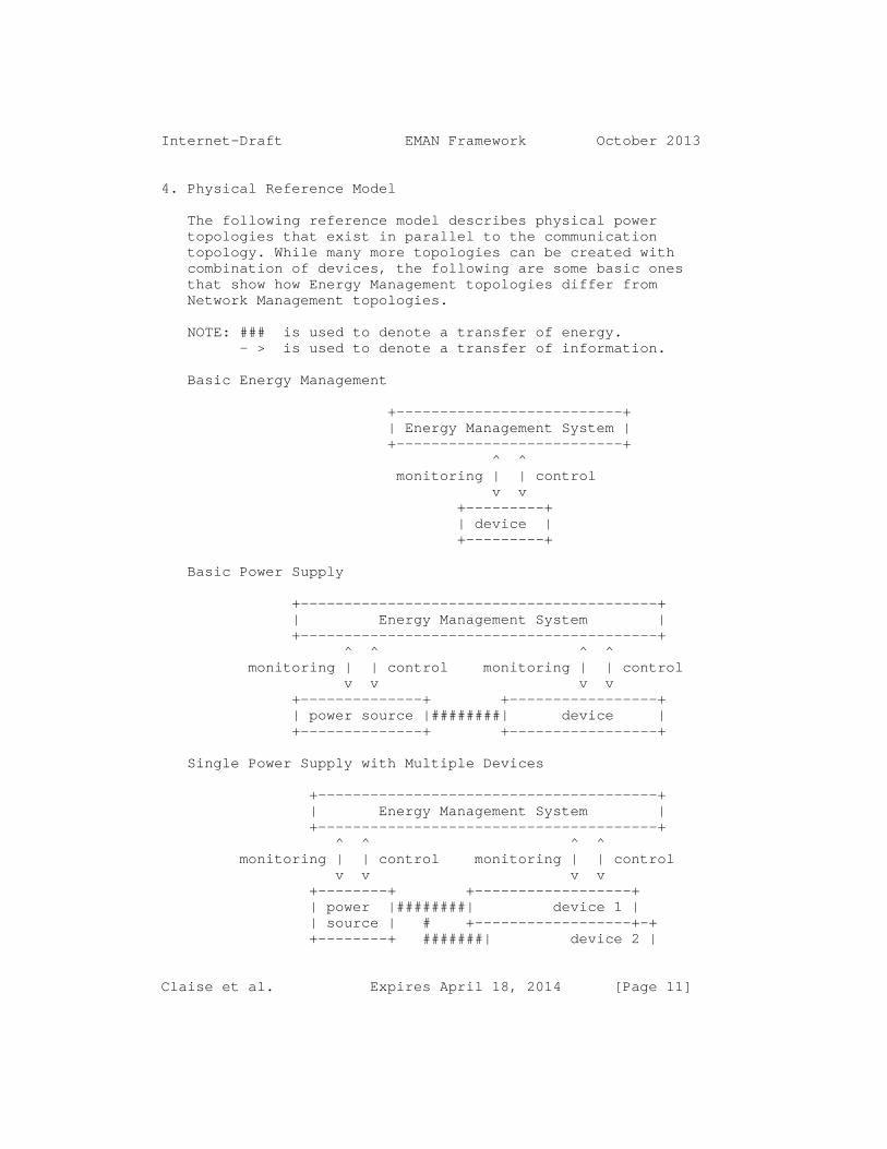
Internet-Draft EMAN Framework October 2013
4. Physical Reference Model
The following reference model describes physical power topologies that exist in parallel to the communication topology. While many more topologies can be created with combination of devices, the following are some basic ones that show how Energy Management topologies differ from Network Management topologies.
NOTE: ### is used to denote a transfer of energy. - > is used to denote a transfer of information.
Basic Energy Management
+--------------------------+ | Energy Management System | +--------------------------+ ^ ^ monitoring | | control v v +---------+ | device | +---------+
Basic Power Supply
+-----------------------------------------+ | Energy Management System | +-----------------------------------------+ ^ ^ ^ ^ monitoring | | control monitoring | | control v v v v +--------------+ +-----------------+ | power source |########| device | +--------------+ +-----------------+
Single Power Supply with Multiple Devices
+---------------------------------------+ | Energy Management System | +---------------------------------------+ ^ ^ ^ ^ monitoring | | control monitoring | | control v v v v +--------+ +------------------+ | power |########| device 1 | | source | # +------------------+-+ +--------+ #######| device 2 |
Claise et al. Expires April 18, 2014 [Page 11]

Internet-Draft EMAN Framework October 2013
# +------------------+-+ #######| device 3 | +------------------+
Multiple Power Supplies with Single Devices
+----------------------------------------------+ | Energy Management System | +----------------------------------------------+ ^ ^ ^ ^ ^ ^ mon. | | ctrl. mon. | | ctrl. mon. | | ctrl. v v v v v v +----------+ +----------+ +----------+ | power |######| device |######| power | | source 1 |######| | | source 2 | +----------+ +----------+ +----------+
5. Not Covered by the Framework
While this framework is intended as a framework for Energy Management in general, there are some areas that are not covered.
Non-Electrical Equipment
The primary focus of this framework is the management of electrical equipment. Non-Electrical equipment can be covered by the framework by providing interfaces that comply with the framework. For example, using the same units for power and energy. Therefore, non-electrical equipment that do not convert-to or present-as equivalent to electrical equipment are not addressed.
Energy Procurement and Manufacturing
While an EnMS may be a central point for corporate reporting, cost computation, environmental impact analysis, and regulatory compliance reporting - Energy Management in this framework excludes energy procurement and the environmental impact of energy use.
As such the framework does not include: o Cost in currency or environmental units of manufacturing a device. o Embedded carbon or environmental equivalences of a device
Claise et al. Expires April 18, 2014 [Page 12]

Internet-Draft EMAN Framework October 2013
o Cost in currency or environmental impact to dismantle or recycle a device. o Supply chain analysis of energy sources for device deployment o Conversion of the usage or production of energy to units expressed from the source of that energy (such as the greenhouse gas emissions associated the transfer of energy from a diesel source).
6. Energy Management Abstraction
This section describes a conceptual model of information that can be used for Energy Management. The classes and categories of attributes in the model are described with rationale for each.
6.1. Conceptual Model
This section describes an information model that addressing issues specific to Energy Management, which complements existing Network Management models.
An information model for Energy Management will need to describe a means to monitor and control devices and components. The model will also need to describe the relationships among and connections between devices and components.
This section proposes a similar conceptual model for devices and components to that used in Network Management: devices, components, and interfaces. This section then defines the additional attributes specific to Energy Management for those entities that are not available in existing Network Management models.
For modeling the devices and components this section describes three classes: a Device (Class), a Component (Class), and a Power Interface (Class). These classes are sub-types of an abstract Energy Object (Class).
Summary of Notation for Modeling Physical Equipment
Physical Modeling (Meta Data) Model Instance --------------------------------------------------------- equipment Energy Object (Class) Energy Object device Device (Class) Device component Component (Class) Component inlet / outlet Power Interface (Class) Power Interface
Claise et al. Expires April 18, 2014 [Page 13]
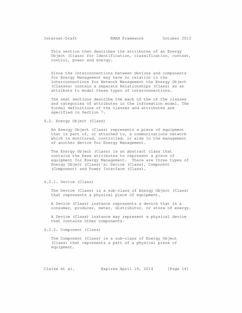
Internet-Draft EMAN Framework October 2013
This section then describes the attributes of an Energy Object (Class) for identification, classification, context, control, power and energy.
Since the interconnections between devices and components for Energy Management may have no relation to the interconnections for Network Management the Energy Object (Classes) contain a separate Relationships (Class) as an attribute to model these types of interconnections.
The next sections describe the each of the of the classes and categories of attributes in the information model. The formal definitions of the classes and attributes are specified in Section 7.
6.2. Energy Object (Class)
An Energy Object (Class) represents a piece of equipment that is part of, or attached to, a communications network which is monitored, controlled, or aids in the management of another device for Energy Management.
The Energy Object (Class) is an abstract class that contains the base attributes to represent a piece of equipment for Energy Management. There are three types of Energy Object (Class)’s: Device (Class), Component (Component) and Power Interface (Class).
6.2.1. Device (Class)
The Device (Class) is a sub-class of Energy Object (Class) that represents a physical piece of equipment.
A Device (Class) instance represents a device that is a consumer, producer, meter, distributor, or store of energy.
A Device (Class) instance may represent a physical device that contains other components.
6.2.2. Component (Class)
The Component (Class) is a sub-class of Energy Object (Class) that represents a part of a physical piece of equipment.
Claise et al. Expires April 18, 2014 [Page 14]

Internet-Draft EMAN Framework October 2013
6.2.3. Power Interface (Class)
A Power Interface (Class) represents the interconnections (inlet, outlet) among devices or components where energy can be provided, received, or both.
The Power Interface (Class) is a sub-class of Energy Object (Class) that represents a physical inlet or outlet.
There are some similarities between Power Interfaces and network interfaces. A network interface can be set to different states, such as sending or receiving data on an attached line. Similarly, a Power Interface can be receiving or providing energy.
A Power Interface (Class) instance can represent (physically) an AC power socket, an AC power cord attached to a device, or an 8P8C (RJ45) PoE socket, etc.
6.3. Energy Object Attributes
This section describes categories of attributes for an Energy Object (Class).
6.3.1. Identification
A Universal Unique Identifier (UUID) [RFC4122] is used to uniquely and persistently identify an Energy Object.
Every Energy Object has an optional unique printable name. Possible naming conventions are: textual DNS name, MAC address of the device, interface ifName, or a text string uniquely identifying the Energy Object. As an example, in the case of IP phones, the Energy Object name can be the device’s DNS name.
Additionally an alternate key is provided to allow an Energy Object to be optionally linked with models in different systems.
6.3.2. Context in General
In order to aid in reporting and in differentiation between Energy Objects, each object optionally contains information establishing its business, site, or organizational context within a deployment.
The Energy Object (Class) contains a category attribute that broadly describes how an instance is used in a
Claise et al. Expires April 18, 2014 [Page 15]

Internet-Draft EMAN Framework October 2013
deployment. The category indicates if the Energy Object is primarily functioning as a consumer, producer, meter, distributor or store of energy.
Given the category and context of an object, an EnMS can summarize or analyze measurements for the site.
6.3.3. Context: Importance
An Energy Object can provide an importance value in the range of 1 to 100 to help rank a device’s use or relative value to the site. The importance range is from 1 (least important) to 100 (most important). The default importance value is 1.
For example: A typical office environment has several types of phones, which can be rated according to their business impact. A public desk phone has a lower importance (for example, 10) than a business-critical emergency phone (for example, 100). As another example: A company can consider that a PC and a phone for a customer-service engineer are more important than a PC and a phone for lobby use.
Although EnMS and administrators can establish their own ranking, the following example is a broad recommendation for commercial deployments [CISCO-EW]:
90 to 100 Emergency response 80 to 90 Executive or business-critical 70 to 79 General or Average 60 to 69 Staff or support 40 to 59 Public or guest 1 to 39 Decorative or hospitality
6.3.4. Context: Keywords
The Energy Object (Class) contains an attribute with context keywords.
An Energy Object can provide a set of keywords that are a list of tags that can be used for grouping, for summary reporting (within or between Energy Management Domains), and for searching.
All alphanumeric characters and symbols (other than a comma), such as #, (, $, !, and &, are allowed. Potential examples are: IT, lobby, HumanResources, Accounting, StoreRoom, CustomerSpace, router, phone, floor2, or SoftwareLab.
Claise et al. Expires April 18, 2014 [Page 16]

Internet-Draft EMAN Framework October 2013
There is no default value for a keyword. Multiple keywords can be assigned to an Energy Object. White spaces before and after the commas are excluded, as well as within a keyword itself. In such cases, commas separate the keywords and no spaces between keywords are allowed. For example, "HR,Bldg1,Private".
6.3.5. Context: Role
The Energy Object (Class) contains a role attribute. The "role description" string indicates the primary purpose the Energy Object serves in the deployment. This could be a string representing the purpose the Energy Object fulfills in the deployment.
Administrators can define any naming scheme for the role. As guidance, a two-word role that combines the service the Energy Object provides along with type can be used [IPENERGY].
Example types of devices: Router, Switch, Light, Phone, WorkStation, Server, Display, Kiosk, HVAC.
Example Services by Line of Business:
Line of Business Service ----------------------------------------------------- Education Student, Faculty, Administration, Athletic Finance Trader, Teller, Fulfillment Manufacturing Assembly, Control, Shipping Retail Advertising, Cashier Support Helpdesk, Management Medical Patient, Administration, Billing
Role as a two-word string: "Faculty Desktop", "Teller Phone", "Shipping HVAC", "Advertising Display", "Helpdesk Kiosk", "Administration Switch".
6.3.6. Context: Domain
The Energy Object (Class) contains a string attribute to indicate membership in an Energy Management Domain. An Energy Management Domain can be any collection of Energy Objects in a deployment, but it is recommended to map 1:1 with a metered or sub-metered portion of the site.
Claise et al. Expires April 18, 2014 [Page 17]

Internet-Draft EMAN Framework October 2013
In building management, a meter refers to the meter provided by the utility used for billing and measuring power to an entire building or unit within a building. A sub-meter refers to a customer- or user-installed meter that is not used by the utility to bill but is instead used to get measurements from sub portions of a building.
An Energy Object should be a member of a single Energy Management Domain therefore one attribute is provided.
6.4. Measurements
The Energy Object (Class) contains attributes to describe power, energy and demand measurements.
An analogy for understanding power versus energy measurements can be made to speed and distance in automobiles. Just as a speedometer indicates the rate of change of distance (speed), a power measurement indicates the rate of transfer of energy. The odometer in an automobile measures the cumulative distance traveled and similarly an energy measurement indicates the accumulated energy transferred.
Demand measurements are averages of power measurements over time. So using the same analogy to an automobile: measuring the average vehicle speed over multiple intervals of time for a given distance travelled, demand is the average power measured over multiple time intervals for a given energy value.
Within this framework, energy will only be quantified in units of watt-hours. Physical devices measuring energy in other units must convert values to watt-hours or be represented by Energy Objects that convert to watt-hours.
6.4.1. Measurements: Power
The Energy Object (Class) contains a Nameplate Power attribute that describes the nominal power as specified by the manufacturer of the device. The EnMS can use the Nameplate Power for provisioning, capacity planning and (potentially) billing.
The Energy Object (Class) has attributes that describe the present power information, along with how that measurement was obtained or derived (e.g., actual, estimated, or static).
Claise et al. Expires April 18, 2014 [Page 18]

Internet-Draft EMAN Framework October 2013
A power measurement is qualified with the units, magnitude and direction of power flow, and is qualified as to the means by which the measurement was made.
Power measurement magnitude conforms to the [IEC61850] definition of unit multiplier for the SI (System International) units of measure. Measured values are represented in SI units obtained by BaseValue * (10 ^ Scale). For example, if current power usage of an Energy Object is 17, it could be 17 W, 17 mW, 17 kW, or 17 mW, depending on the value of the scaling factor. 17 W implies that the BaseValue is 17 and Scale = 0, whereas 17 mW implies BaseValue = 17 and ScaleFactor = -3.
An Energy Object (Class) indicates how the power measurement was obtained with a caliber and accuracy attribute that indicates: o Whether the measurements were made at the device itself or at a remote source. o Description of the method that was used to measure the power and whether this method can distinguish actual or estimated values. o Accuracy for actual measured values
6.4.2. Measurements: Power Attributes
The Energy Object (Class) contains an optional attribute that describes Power Attribute information reflecting the electrical characteristics of the measurement. These Power Attributes adhere to the [IEC-61850-7-2] standard for describing AC measurements.
6.4.3. Measurements: Energy
The Energy Object (Class) contains optional attributes that represent the energy used, received, produced and or stored. Typically only devices or components that can measure actual power will have the ability to measure energy.
6.4.4. Measurements: Demand
The Energy Object (Class) contains optional attributes that represent demand information over time. Typically only devices or components that can report actual power are capable of measuring demand.
Claise et al. Expires April 18, 2014 [Page 19]

Internet-Draft EMAN Framework October 2013
6.5. Control
The Energy Object (Class) contains a Power State Set (Class) attribute that represents the set of Power States a device or component supports.
A Power State describes a condition or mode of a device or component. While Power States are typically used for control they may be used for monitoring only.
A device or component is expected to support at least one set of Power States consisting of at least two states, an on state and an off state.
There are many existing standards describing device and component Power States. The framework supports modeling a mixed set of Power States defined in different standards. A basic example is given by the three Power States defined in IEEE1621 [IEEE1621]: on, off, and sleep. The DMTF [DMTF], ACPI [ACPI], and PWG all define larger numbers of Power States.
The semantics of a Power State are specified by a) the functionality provided by an Energy Object in this state, b) a limitation of the power that an Energy Object uses in this state, c) a combination of a) and b)
The semantics of a Power State should be clearly defined. Limitation (curtailment) of the power used by an Energy Object in a state may be specified by: o an absolute power value o a percentage value of power relative to the energy object’s nameplate power o an indication of power relative to another power state. For example: Specify that power in state A is less than in state B. o For supporting Power State management an Energy Object provides statistics on Power States including the time an Energy Object spent in a certain Power State and the number of times an Energy Object entered a power state.
When requesting an Energy Object to enter a Power State an indication of the Power State’s name or number can be used. Optionally an absolute or percentage of Nameplate Power can be provided to allow the Energy Object to transition to a nearest or equivalent Power State.
Claise et al. Expires April 18, 2014 [Page 20]

Internet-Draft EMAN Framework October 2013
When an Energy Object is set to a particular Power State, the represented device or component may be busy. The Energy Object should set the desired Power State and then update the actual Power State when the device or component changes. There are then two Power State (Class) control attributes: actual and requested.
The following sections describe well-known Power States for devices and components that should be modeled in the information model.
6.5.1. Power State Sets
There are several standards and implementations of Power State Sets. The Energy Object (Class) support modeling one or multiple Power State Set implementation(s) on the device or component concurrently.
There are currently three Power State Sets advocated: IEEE1621(256) - [IEEE1621] DMTF(512) - [DMTF] EMAN(768) - [EMAN-MON-MIB]
The respective specific states related to each Power State Set are specified in the following sections. The guidelines for the modification of Power State Sets are specified in the IANA Considerations Section.
6.5.2. Power State Set: IEEE1621
The IEEE1621 Power State Set [IEEE1621] consists of 3 rudimentary states: on, off or sleep.
In IEEE1621 devices are limited to the three basic power states’ on, sleep, and off. Any additional power states are variants of one of the basic states rather than a fourth state [IEEE1621].
6.5.3. Power State Set: DMTF
The DMTF [DMTF] standards organization has defined a power profile standard based on the CIM (Common Information Model) model that consists of 15 power states:
{ON (2), SleepLight (3), SleepDeep (4), Off-Hard (5), Off- Soft (6), Hibernate(7), PowerCycle Off-Soft (8), PowerCycle Off-Hard (9), MasterBus reset (10), Diagnostic Interrupt (11), Off-Soft-Graceful (12), Off-Hard Graceful (13),
Claise et al. Expires April 18, 2014 [Page 21]
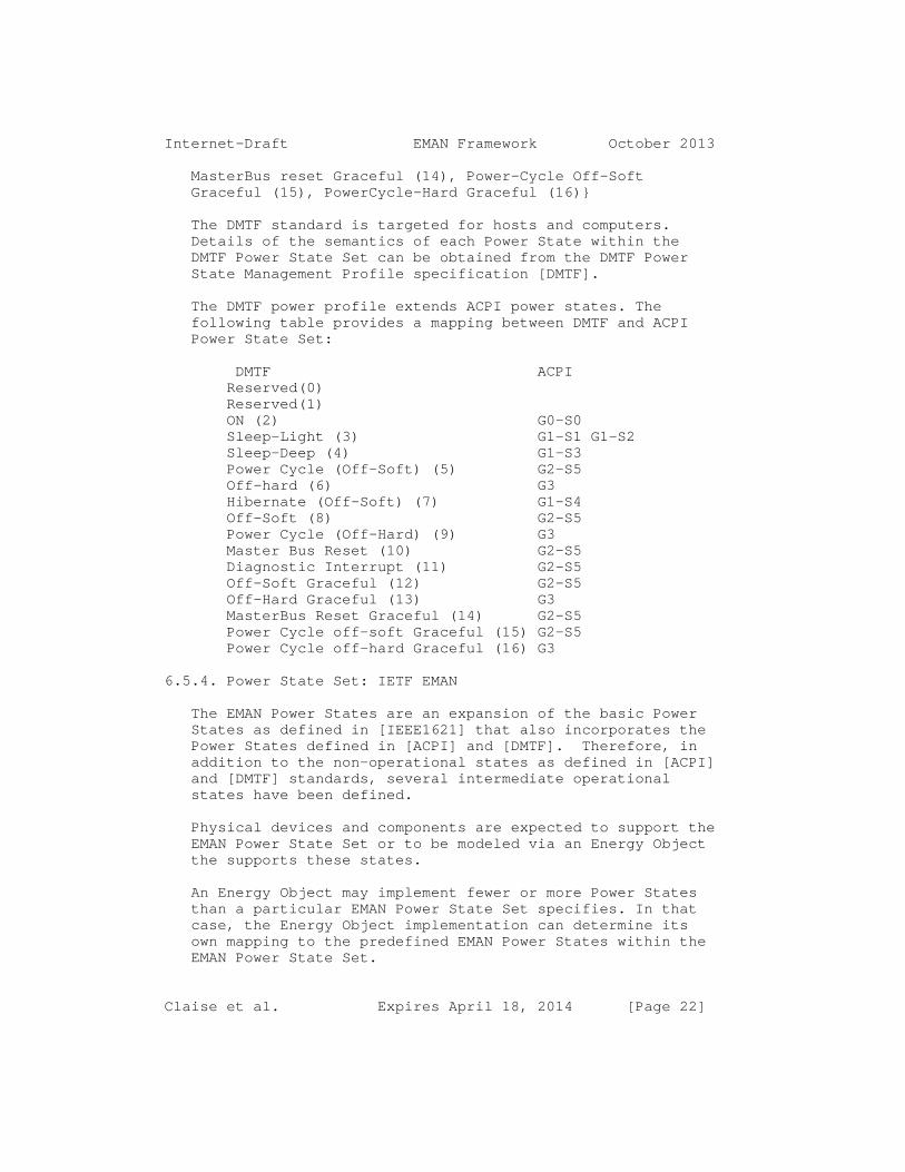
Internet-Draft EMAN Framework October 2013
MasterBus reset Graceful (14), Power-Cycle Off-Soft Graceful (15), PowerCycle-Hard Graceful (16)}
The DMTF standard is targeted for hosts and computers. Details of the semantics of each Power State within the DMTF Power State Set can be obtained from the DMTF Power State Management Profile specification [DMTF].
The DMTF power profile extends ACPI power states. The following table provides a mapping between DMTF and ACPI Power State Set:
DMTF ACPI Reserved(0) Reserved(1) ON (2) G0-S0 Sleep-Light (3) G1-S1 G1-S2 Sleep-Deep (4) G1-S3 Power Cycle (Off-Soft) (5) G2-S5 Off-hard (6) G3 Hibernate (Off-Soft) (7) G1-S4 Off-Soft (8) G2-S5 Power Cycle (Off-Hard) (9) G3 Master Bus Reset (10) G2-S5 Diagnostic Interrupt (11) G2-S5 Off-Soft Graceful (12) G2-S5 Off-Hard Graceful (13) G3 MasterBus Reset Graceful (14) G2-S5 Power Cycle off-soft Graceful (15) G2-S5 Power Cycle off-hard Graceful (16) G3
6.5.4. Power State Set: IETF EMAN
The EMAN Power States are an expansion of the basic Power States as defined in [IEEE1621] that also incorporates the Power States defined in [ACPI] and [DMTF]. Therefore, in addition to the non-operational states as defined in [ACPI] and [DMTF] standards, several intermediate operational states have been defined.
Physical devices and components are expected to support the EMAN Power State Set or to be modeled via an Energy Object the supports these states.
An Energy Object may implement fewer or more Power States than a particular EMAN Power State Set specifies. In that case, the Energy Object implementation can determine its own mapping to the predefined EMAN Power States within the EMAN Power State Set.
Claise et al. Expires April 18, 2014 [Page 22]

Internet-Draft EMAN Framework October 2013
There are twelve EMAN Power States that expand on [IEEE1621]. The expanded list of Power States is derived from [CISCO-EW] and is divided into six operational states and six non-operational states.
The lowest non-operational state is 1 and the highest is 6. Each non-operational state corresponds to an [ACPI] Global and System state between G3 (hard-off) and G1 (sleeping). Each operational state represents a performance state, and may be mapped to [ACPI] states P0 (maximum performance power) through P5 (minimum performance and minimum power).
In each of the non-operational states (from mechoff(1) to ready(6)), the Power State preceding it is expected to have a lower Power value and a longer delay in returning to an operational state:
mechoff(1) : An off state where no Energy Object features are available. The Energy Object is unavailable. No energy is being consumed and the power connector can be removed.
softoff(2) : Similar to mechoff(1), but some components remain powered or receive trace power so that the Energy Object can be awakened from its off state. In softoff(2), no context is saved and the device typically requires a complete boot when awakened.
hibernate(3): No Energy Object features are available. The Energy Object may be awakened without requiring a complete boot, but the time for availability is longer than sleep(4). An example for state hibernate(3) is a save to-disk state where DRAM context is not maintained. Typically, energy consumption is zero or close to zero.
sleep(4) : No Energy Object features are available, except for out-of-band management, such as wake- up mechanisms. The time for availability is longer than standby(5). An example for state sleep(4) is a save-to-RAM state, where DRAM context is maintained. Typically, energy consumption is close to zero.
standby(5) : No Energy Object features are available, except for out-of-band management, such as wake- up mechanisms. This mode is analogous to cold-standby. The time for availability is longer than ready(6). For example processor context is may not be maintained. Typically, energy consumption is close to zero.
Claise et al. Expires April 18, 2014 [Page 23]

Internet-Draft EMAN Framework October 2013
ready(6) : No Energy Object features are available, except for out-of-band management, such as wake- up mechanisms. This mode is analogous to hot-standby. The Energy Object can be quickly transitioned into an operational state. For example, processors are not executing, but processor context is maintained.
lowMinus(7) : Indicates some Energy Object features may not be available and the Energy Object has taken measures or selected options to use less energy than low(8).
low(8) : Indicates some features may not be available and the Energy Object has taken measures or selected options to use less energy than mediumMinus(9).
mediumMinus(9): Indicates all Energy Object features are available but the Energy Object has taken measures or selected options to use less energy than medium(10).
medium(10) : Indicates all Energy Object features are available but the Energy Object has taken measures or selected options to use less energy than highMinus(11).
highMinus(11): Indicates all Energy Object features are available and has taken measures or selected options to use less energy than high(12).
high(12) : Indicates all Energy Object features are available and the Energy Object may use the maximum energy as indicated by the Nameplate Power.
Claise et al. Expires April 18, 2014 [Page 24]

Internet-Draft EMAN Framework October 2013
6.5.5. Power State Sets Comparison
A comparison of Power States from different Power State Sets can be seen in the following table: IEEE1621 DMTF ACPI EMAN
Non-operational states off Off-Hard G3, S5 MechOff(1) off Off-Soft G2, S5 SoftOff(2) off Hibernate G1, S4 Hibernate(3) sleep Sleep-Deep G1, S3 Sleep(4) sleep Sleep-Light G1, S2 Standby(5) sleep Sleep-Light G1, S1 Ready(6)
Operational states: on on G0, S0, P5 LowMinus(7) on on G0, S0, P4 Low(8) on on G0, S0, P3 MediumMinus(9) on on G0, S0, P2 Medium(10) on on G0, S0, P1 HighMinus(11) on on G0, S0, P0 High(12)
6.6. Relationships
The Energy Object (Class) contains a set of Relationship (Class) attributes to model the relationships between devices and components. Two Energy Objects can establish an Energy Object Relationship to model the deployment topology with respect to Energy Management.
Relationships are modeled with a Relationship (Class) that contains the UUID of the other participant in the relationship and a name that describes the type of relationship [CHEN]. The types of relationships are: Power Source, Metering, and Aggregations.
o A Power Source Relationship is relationship where one Energy Object provides power to one or more Energy Objects. The Power Source Relationship gives a view of the physical wiring topology. For example: a data center server receiving power from two specific Power Interfaces from two different PDUs.
Claise et al. Expires April 18, 2014 [Page 25]

Internet-Draft EMAN Framework October 2013
Note: A Power Source Relationship may or may not change as the direction of power changes between two Energy Objects. The relationship may remain to indicate the change of power direction was unintended or an error condition.
o A Metering Relationship is relationship where one Energy Object measures power, energy, demand or Power Attributes of one or more other Energy Objects. The Metering Relationship gives the view of the metering topology. Physical meters can be placed anywhere in a power distribution tree. For example, utility meters monitor and report accumulated power consumption of the entire building. Logically, the metering topology overlaps with the wiring topology, as meters are connected to the wiring topology. A typical example is meters that clamp onto the existing wiring.
o An Aggregation Relationship is a relationship where one Energy Object aggregates Energy Management information of one or more other Energy Objects. The Aggregation Relationship gives a model of devices that may aggregate (sum, average, etc) values for other devices. The Aggregation Relationship is slightly different compared to the other relationships as this refers more to a management function.
In some situations, it is not possible to discover the Energy Object relationships, and an EnMS or administrator must set them. Given that relationships can be assigned manually, the following sections describe guidelines for use.
6.6.1. Relationship Conventions and Guidelines
This Energy Management framework does not impose many "MUST" rules related to Energy Object Relationships. There are always corner cases that could be excluded with too strict specifications of relationships. However, the framework proposes a series of guidelines, indicated with "SHOULD" and "MAY".
6.6.2. Guidelines: Power Source
Power Source relationships are intended to identify the connections between Power Interfaces. This is analogous to
Claise et al. Expires April 18, 2014 [Page 26]

Internet-Draft EMAN Framework October 2013
a Layer 2 connection in networking devices (a "one-hop connection").
The preferred modeling would be for Power Interfaces to participate in Power Source Relationships. It some cases Energy Objects may not have the capability to model Power Interfaces. Therefore a Power Source Relationship can be established between two Energy Objects or two non-connected Power Interfaces.
While strictly speaking Components and Power Interfaces on the same Device do provide or receive energy from each other, the Power Source relationship is intended to show energy transfer between Devices. Therefore the relationship is implied when on the same Device.
An Energy Object SHOULD NOT establish a Power Source Relationship with a Component. o A Power Source Relationship SHOULD be established with the next known Power Interface in the wiring topology.
o The next known Power Interface in the wiring topology would be the next device implementing the framework. In some cases the domain of devices under management may include some devices that do not implement the framework. In these cases, the Power Source relationship can be established with the next device in the topology that implements the framework and logically shows the Power Source of the device.
o Transitive Power Source relationships SHOULD NOT be established. For example, if an Energy Object A has a Power Source Relationship "Poweredby" with the Energy Object B, and if the Energy Object B has a Power Source Relationship "Poweredby" with the Energy Object C, then the Energy Object A SHOULD NOT have a Power Source Relationship "Poweredby" with the Energy Object C.
6.6.3. Guidelines: Metering Relationship
Metering Relationships are intended to show when one device acting as a meter is measuring the power or energy at a point in a power distribution system. Since one point of a power distribution system may cover many devices within a wiring topology, this relationship type can be seen as a set.
Claise et al. Expires April 18, 2014 [Page 27]

Internet-Draft EMAN Framework October 2013
Some devices, however, may include measuring hardware for components, and outlets or for the entire device. For example, some PDUs may have the ability to measure power for each outlet and are commonly referred to as metered-by- outlet. Others may be able to control power at each power outlet but can only measure power at the power inlet - commonly referred to as metered-by-device.
While the Metering Relationship could be used to represent a device as metered-by-outlet or metered-by-device, the Metering Relationship SHOULD be used to model the relationship between a meter and all devices covered by the meter downstream in the power distribution system
In general: o A Metering Relationship MAY be established with any other Energy Object, Component, or Power Interface.
o Transitive Metering Relationships MAY be used.
o When there is a series of meters for one Energy Object, the Energy Object MAY establish a Metering relationship with one or more of the meters.
6.6.4. Guidelines: Aggregation
Aggregation relationships are intended to identify when one device is used to accumulate values from other devices. Typically this is for energy or power values among devices and not for Components or Power Interfaces on the same device.
The intent of Aggregation relationships is to indicate when one device is providing aggregate values for a set of other devices when it is not obvious from the power source or simple containment within a device.
Establishing aggregation relationships within the same device would make modeling more complex and the aggregated values can be implied from the use of Power Inlets, outlet and Energy Object values on the same device.
Since an EnMS is naturally a point of aggregation it is not necessary to model aggregation for Energy Management Systems.
The Aggregation Relationship is intended for power and energy. It MAY be used for aggregation of other values from
Claise et al. Expires April 18, 2014 [Page 28]

Internet-Draft EMAN Framework October 2013
the information model, but the rules and logical ability to aggregate each attribute is out of scope for this document.
In general: o A Device SHOULD NOT establish an Aggregation Relationship with Components contained on the same device. o A Device SHOULD NOT establish an Aggregation Relationship with the Power Interfaces contained on the same device. o A Device SHOULD NOT establish an Aggregation Relationship with an EnMS. o Aggregators SHOULD log or provide notification in the case of errors or missing values while performing aggregation.
6.6.5. Energy Object Relationship Extensions
This framework for Energy Management is based on three relationship types: Aggregation , Metering, and Power Source. This framework is defined with possible future extension of new Energy Object Relationships in mind. For example: o Some Devices that may not be IP connected. This can be modeled with a proxy relationship to an Energy Object within the domain. This type of proxy relationship is left for further development. o A Power Distribution Unit (PDU) that allows devices and components like outlets to be "ganged" together as a logical entity for simplified management purposes, could be modeled with an extension called a "gang relationship", whose semantics would specify the Energy Objects’ grouping.
7. Energy Management Information Model
This section presents an information model expression of the concepts in this framework as a reference for implementers. The information model is implemented as a MIB in the different related IETF EMAN documents. However, other programming structures with different data models could be used as well.
Data modeling specifications of this information model may where needed specify which attributes are required or optional.
Claise et al. Expires April 18, 2014 [Page 29]

Internet-Draft EMAN Framework October 2013
EDITORs NOTE: The working group is converging on the use of code/pseudo-code rather than ascii UML diagram. If so we would have to define primitive type as reference (eg. Int, string, etc)If agreeable we can indicate a BNF syntax in a formal syntax section, use a schema definition from JSON/XML, or use the following table if obvious:
Syntax
UML Construct [ISO-IEC-19501-2005] Equivalent Notation -------------------- ------------------------------------ Notes // Notes Class (Generalization) CLASS name {member..} Sub-Class (Specialization) CLASS subclass EXTENDS superclass {member..} Class Member (Attribute) attribute : type
Claise et al. Expires April 18, 2014 [Page 30]

Internet-Draft EMAN Framework October 2013
Model
CLASS EnergyObject {
// identification / classification index : int identifier : uuid alternatekey : string
// context domainName : string role : string keywords [0..n] : string importance : int
// relationship relationships [0..n] : Relationship
// measurements nameplate : Nameplate power : PowerMeasurement energy : EnergyMeasurment demand : DemandMeasurement
// control powerControl [0..n] : PowerStateSet }
CLASS PowerInterface EXTENDS EnergyObject{ eoIfType : enum { inlet, outlet, both} }
CLASS Device EXTENDS EnergyObject { eocategory : enum { producer, consumer, meter, distributor, store } powerInterfaces[0..n]: PowerInterface components [0..n] Component }
CLASS Component EXTENDS EnergyObject eocategory : enum { producer, consumer, meter, distributor, store } powerInterfaces[0..n]: PowerInterface components [0..n] Component
} // EDITOR NOTE: Component could sub-class from Device
Claise et al. Expires April 18, 2014 [Page 31]

Internet-Draft EMAN Framework October 2013
CLASS Nameplate { nominalPower : PowerMeasurement details : URI }
CLASS Relationship { relationshipType : enum { meters, meteredby, powers, poweredby, aggregates, aggregatedby } relationshipObject : uuid }
CLASS Measurement { multiplier: enum { -24..24} caliber : enum { actual, estimated, static } accuracy : enum { 0..10000} // hundreds of percent }
CLASS PowerMeasurement EXTENDS Measurement { value : long units : "W" powerAttribute : PowerAttribute }
CLASS EnergyMeasurement EXTENDS Measurement { startTime : time units : "kWh" provided : long used : long produced : long stored : long }
CLASS TimedMeasurement EXTENDS Measurement { startTime : timestamp value : Measurement maximum : Measurement }
CLASS TimeInterval { value : long units : enum { seconds, miliseconds,...} }
CLASS DemandMeasurement EXTENDS Measurement { intervalLength : TimeInterval interval : long intervalMode : enum { periodic, sliding, total }
Claise et al. Expires April 18, 2014 [Page 32]

Internet-Draft EMAN Framework October 2013
intervalWindow : TimeInterval sampleRate : TimeInterval status : enum { active, inactive } measurements[0..n] : TimedMeasurements }
CLASS PowerStateSet { powerSetIdentifier : int name : string powerStates [0..n] : PowerState operState : int adminState : int reason : string configuredTime : timestamp }
CLASS PowerState { powerStateIdentifier : int name : string cardinality : int maximumPower : PowerMeasurement totalTimeInState : time entryCount : long }
CLASS PowerAttribute {
acQuality : ACQuality }
CLASS ACQuality { acConfiguration : enum {SNGL, DEL,WYE} avgVoltage : long avgCurrent : long frequency : long unitMultiplier : int accuracy : int totalActivePower : long totalReactivePower : long totalApparentPower : long totalPowerFactor : long phases [0..2] : ACPhase }
CLASS ACPhase { phaseIndex : long avgCurrent : long activePower : long reactivePower : long
Claise et al. Expires April 18, 2014 [Page 33]

Internet-Draft EMAN Framework October 2013
apparentPower : long powerFactor : long }
CLASS DelPhase EXTENDS ACPhase { phaseToNextPhaseVoltage : long thdVoltage : long thdCurrent : long }
CLASS WYEPhase EXTENDS ACPhase { phaseToNeutralVoltage : long thdCurrent : long thdVoltage : long }
8. Modeling Relationships between Devices
In this section we give examples of how to use the EMAN information model to model physical topologies. Where applicable, we show how the framework can be applied when devices can be modeled with Power Interfaces. We also show how the framework can be applied when devices cannot be modeled with Power Interfaces but only monitored or control as a whole. For instance, a PDU may only be able to measure power and energy for the entire unit without the ability to distinguish among the inlets or outlets.
8.1. Power Source Relationship
The Power Source relationship is used to model the interconnections between devices, components and/Power Interfaces to indicate the source of energy for a device. In the following examples we show variations on modeling the reference topologies using relationships.
Given for all cases:
Device W: A computer with one power supply. Power Interface 1 is an inlet for Device W.
Device X: A computer with two power supplies. Power Interface 1 and power interface 2 are both inlets for Device X.
Device Y: A PDU with multiple Power Interfaces numbered 0..10. Power Interface 0 is an inlet and Power Interface 1..10 are outlets.
Claise et al. Expires April 18, 2014 [Page 34]

Internet-Draft EMAN Framework October 2013
Device Z: A PDU with multiple Power Interfaces numbered 0..10. Power Interface 0 is an inlet and Power Interface 1..10 are outlets.
Case 1: Simple Device with one Source
Physical Topology:
o Device W inlet 1 is plugged into Device Y outlet 8.
With Power Interfaces:
o Device W has an Energy Object representing the computer itself as well as one Power Interface defined as an inlet. o Device Y would have an Energy Object representing the PDU itself (the Device), with a Power Interface 0 defined as an inlet and Power Interfaces 1..10 defined as outlets.
The interfaces of the devices would have a Power Source Relationship such that: Device W inlet 1 is powered by Device Y outlet 8.
+-------+------+ poweredBy +------+----------+ | PDU Y | PI 8 |-----------------| PI 1 | Device W | +-------+------+ powers +------+----------+
Without Power Interfaces:
o Device W has an Energy Object representing the computer. o Device Y would have an Energy Object representing the PDU.
The devices would have a Power Source Relationship such that: Device W is powered by Device Y.
+----------+ poweredBy +------------+ | PDU Y |-----------------| Device W | +----------+ powers +------------+
Case 2: Multiple Inlets
Physical Topology:
Claise et al. Expires April 18, 2014 [Page 35]
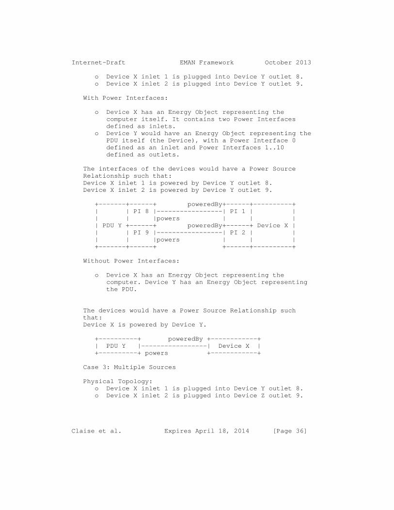
Internet-Draft EMAN Framework October 2013
o Device X inlet 1 is plugged into Device Y outlet 8. o Device X inlet 2 is plugged into Device Y outlet 9.
With Power Interfaces:
o Device X has an Energy Object representing the computer itself. It contains two Power Interfaces defined as inlets. o Device Y would have an Energy Object representing the PDU itself (the Device), with a Power Interface 0 defined as an inlet and Power Interfaces 1..10 defined as outlets.
The interfaces of the devices would have a Power Source Relationship such that: Device X inlet 1 is powered by Device Y outlet 8. Device X inlet 2 is powered by Device Y outlet 9.
+-------+------+ poweredBy+------+----------+ | | PI 8 |-----------------| PI 1 | | | | |powers | | | | PDU Y +------+ poweredBy+------+ Device X | | | PI 9 |-----------------| PI 2 | | | | |powers | | | +-------+------+ +------+----------+
Without Power Interfaces:
o Device X has an Energy Object representing the computer. Device Y has an Energy Object representing the PDU.
The devices would have a Power Source Relationship such that: Device X is powered by Device Y.
+----------+ poweredBy +------------+ | PDU Y |-----------------| Device X | +----------+ powers +------------+
Case 3: Multiple Sources
Physical Topology: o Device X inlet 1 is plugged into Device Y outlet 8. o Device X inlet 2 is plugged into Device Z outlet 9.
Claise et al. Expires April 18, 2014 [Page 36]

Internet-Draft EMAN Framework October 2013
With Power Interfaces:
o Device X has an Energy Object representing the computer itself. It contains two Power Interface defined as inlets. o Device Y would have an Energy Object representing the PDU itself (the Device), with a Power Interface 0 defined as an inlet and Power Interfaces 1..10 defined as outlets. o Device Z would have an Energy Object representing the PDU itself (the Device), with a Power Interface 0 defined as an inlet and Power Interfaces 1..10 defined as outlets.
The interfaces of the devices would have a Power Source Relationship such that: Device X inlet 1 is powered by Device Y outlet 8. Device X inlet 2 is powered by Device Z outlet 9.
+-------+------+ poweredBy+------+----------+ | PDU Y | PI 8 |-----------------| PI 1 | | | | |powers | | | +-------+------+ +------+ | | Device X | +-------+------+ poweredBy+------+ | | PDU Z | PI 9 |-----------------| PI 2 | | | | |powers | | | +-------+------+ +------+----------+
Without Power Interfaces:
o Device X has an Energy Object representing the computer. Device Y and Z would both have respective Energy Objects representing each entire PDU.
The devices would have a Power Source Relationship such that: Device X is powered by Device Y and powered by Device Z.
+----------+ poweredBy +------------+ | PDU Y |---------------------| Device X | +----------+ powers +------------+
+----------+ poweredBy +------------+ | PDU Z |---------------------| Device X | +----------+ powers +------------+
Claise et al. Expires April 18, 2014 [Page 37]

Internet-Draft EMAN Framework October 2013
8.2. Metering Relationship
A meter in a power distribution system can logically measure the power or energy for all devices downstream from the meter in the power distribution system. As such, a Metering relationship can be seen as a relationship between a meter and all of the devices downstream from the meter.
We define in this case a Metering relationship between a meter and devices downstream from the meter.
+-----+---+ meteredBy +--------+ poweredBy +-------+ |Meter| PI|--------------| switch |-------------| phone | +-----+---+ meters +--------+ powers +-------+ | | | meteredBy | +-------------------------------------------+ meters
In cases where the Power Source topology cannot be discovered or derived from the information available in the Energy Management Domain, the metering topology can be used to relate the upstream meter to the downstream devices in the absence of specific Power Source relationships.
A Metering Relationship can occur between devices that are not directly connected, as shown in the following figure:
+---------------+ | Device 1 | +---------------+ | PI | +---------------+ | +---------------+ | Meter | +---------------+ . . . meters meters meters +----------+ +----------+ +-----------+ | Device A | | Device B | | Device C | +----------+ +----------+ +-----------+
An analogy to communications networks would be modeling connections between servers (meters) and clients (devices) when the complete Layer 2 topology between the servers and clients is not known.
Claise et al. Expires April 18, 2014 [Page 38]

Internet-Draft EMAN Framework October 2013
8.3. Aggregation Relationship
Some devices can act as aggregation points for other devices. For example, a PDU controller device may contain the summation of power and energy readings for many PDU devices. The PDU controller will have aggregate values for power and energy for a group of PDU devices.
This aggregation is independent of the physical power or communication topology.
The functions that the aggregation point may perform include the calculation of values such as average, count, maximum, median, minimum, or the listing (collection) of the aggregation values, etc. Based on the experience gained on aggregations at the IETF [draft-ietf-ipfix-a9n-08], the aggregation function in the EMAN framework is limited to the summation.
When aggregation occurs across a set of entities, values to be aggregated may be missing for some entities. The EMAN framework does not specify how these should be treated, as different implementations may have good reason to take different approaches. One common treatment is to define the aggregation as missing if any of the constituent elements are missing (useful to be most precise). Another is to treat the missing value as zero (useful to have continuous data streams).
The specifications of aggregation functions are out of scope of the EMAN framework, but must be clearly specified by the equipment vendor.
9. Relationship to Other Standards
This Energy Management framework uses, as much as possible, existing standards especially with respect to information modeling and data modeling [RFC3444].
The data model for power- and energy-related objects is based on [IEC61850].
Specific examples include: o The scaling factor, which represents Energy Object usage magnitude, conforms to the [IEC61850] definition of unit multiplier for the SI (System International) units of measure.
Claise et al. Expires April 18, 2014 [Page 39]

Internet-Draft EMAN Framework October 2013
o The electrical characteristic is based on the ANSI and IEC Standards, which require that we use an accuracy class for power measurement. ANSI and IEC define the following accuracy classes for power measurement: o IEC 62053-22 60044-1 class 0.1, 0.2, 0.5, 1 3. o ANSI C12.20 class 0.2, 0.5 o The electrical characteristics and quality adhere closely to the [IEC61850-7-2] standard for describing AC measurements. o The power state definitions are based on the DMTF Power State Profile and ACPI models, with operational state extensions.
10. Security Considerations
Regarding the data attributes specified here, some or all may be considered sensitive or vulnerable in some network environments. Reading or writing these attributes without proper protection such as encryption or access authorization may have negative effects on the network capabilities.
10.1. Security Considerations for SNMP
Readable objects in MIB modules (i.e., objects with a MAX- ACCESS other than not-accessible) may be considered sensitive or vulnerable in some network environments. It is important to control GET and/or NOTIFY access to these objects and possibly to encrypt the values of these objects when sending them over the network via SNMP.
The support for SET operations in a non-secure environment without proper protection can have a negative effect on network operations.
For example: o Unauthorized changes to the Energy Management Domain or business context of a device may result in misreporting or interruption of power. o Unauthorized changes to a power state may disrupt the power settings of the different devices, and therefore the state of functionality of the respective devices. o Unauthorized changes to the demand history may disrupt proper accounting of energy usage.
With respect to data transport, SNMP versions prior to SNMPv3 did not include adequate security. Even if the
Claise et al. Expires April 18, 2014 [Page 40]

Internet-Draft EMAN Framework October 2013
network itself is secure (for example, by using IPsec), there is still no secure control over who on the secure network is allowed to access and GET/SET (read/change/create/delete) the objects in these MIB modules.
It is recommended that implementers consider the security features as provided by the SNMPv3 framework (see [RFC3410], section 8), including full support for the SNMPv3 cryptographic mechanisms (for authentication and privacy). Further, deployment of SNMP versions prior to SNMPv3 is not recommended. Instead, it is recommended to deploy SNMPv3 and to enable cryptographic security. It is then a customer/operator responsibility to ensure that the SNMP entity giving access to an instance of these MIB modules is properly configured to give access to the objects only to those principals (users) that have legitimate rights to GET or SET (change/create/delete) them.
11. IANA Considerations 11.1. IANA Registration of new Power State Sets
This document specifies an initial set of Power State Sets. The list of these Power State Sets with their numeric identifiers is given is Section 6. IANA maintains the lists of Power State Sets.
New assignments for Power State Set are administered by IANA through Expert Review [RFC5226], i.e., review by one of a group of experts designated by an IETF Area Director. The group of experts MUST check the requested state for completeness and accuracy of the description. A pure vendor specific implementation of Power State Set shall not be adopted; since it would lead to proliferation of Power State Sets.
Power states in a Power State Set are limited to 255 distinct values. New Power State Set must be assigned the next available numeric identifier that is a multiple of 256.
11.1.1. IANA Registration of the IEEE1621 Power State Set
This document specifies a set of values for the IEEE1621 Power State Set [IEEE1621]. The list of these values with their identifiers is given in Section 6.6.2. IANA created
Claise et al. Expires April 18, 2014 [Page 41]

Internet-Draft EMAN Framework October 2013
a new registry for IEEE1621 Power State Set identifiers and filled it with the initial list of identifiers.
New assignments (or potentially deprecation) for the IEEE1621 Power State Set is administered by IANA through Expert Review [RFC5226], i.e., review by one of a group of experts designated by an IETF Area Director. The group of experts must check the requested state for completeness and accuracy of the description.
11.1.2. IANA Registration of the DMTF Power State Set
This document specifies a set of values for the DMTF Power State Set. The list of these values with their identifiers is given in Section 6. IANA has created a new registry for DMTF Power State Set identifiers and filled it with the initial list of identifiers.
New assignments (or potentially deprecation) for the DMTF Power State Set is administered by IANA through Expert Review [RFC5226], i.e., review by one of a group of experts designated by an IETF Area Director. The group of experts must check the conformance with the DMTF standard [DMTF], on the top of checking for completeness and accuracy of the description.
11.1.3. IANA Registration of the EMAN Power State Set
This document specifies a set of values for the EMAN Power State Set. The list of these values with their identifiers is given in Section 6.6.4. IANA has created a new registry for EMAN Power State Set identifiers and filled it with the initial list of identifiers.
New assignments (or potentially deprecation) for the EMAN Power State Set is administered by IANA through Expert Review [RFC5226], i.e., review by one of a group of experts designated by an IETF Area Director. The group of experts must check the requested state for completeness and accuracy of the description.
11.1.4. Batteries Power State Set
Batteries have operational and administrational states that could be represented as a Power State Set. Since the work for battery management is parallel to this document, we are not proposing any Power State Sets for batteries at this time.
Claise et al. Expires April 18, 2014 [Page 42]

Internet-Draft EMAN Framework October 2013
11.2. Updating the Registration of Existing Power State Sets
With the evolution of standards, over time, it may be important to deprecate some of the existing the Power State Sets, or to add or deprecate some Power States within a Power State Set.
The registrant shall publish an Internet-draft or an individual submission with the clear specification on deprecation of Power State Sets or Power States registered with IANA. The deprecation or addition shall be administered by IANA through Expert Review [RFC5226], i.e., review by one of a group of experts designated by an IETF Area Director. The process should also allow for a mechanism for cases where others have significant objections to claims on deprecation of a registration.
12. References
Normative References
[RFC2119] Bradner, S., "Key words for use in RFCs to Indicate Requirement Levels", BCP 14, RFC 2119, March 1997
[RFC3410] Case, J., Mundy, R., Partain, D., and B. Stewart, "Introduction and Applicability Statements for Internet Standard Management Framework ", RFC 3410, December 2002
[RFC4122] Leach, P., Mealling, M., and R. Salz," A Universally Unique Identifier (UUID) URN Namespace", RFC 4122, July 2005
[RFC5226] Narten, T., and H. Alvestrand, "Guidelines for Writing an IANA Considerations Section in RFCs", RFC 5226, May 2008
[RFC6933] Bierman, A. and K. McCloghrie, "Entity MIB (Version4)", RFC 6933, May 2013
[RFC3444] Pras, A., Schoenwaelder, J. "On the Differences between Information Models and Data Models", RFC 3444, January 2003
[ISO-IEC-19501-2005] ISO/IEC 19501:2005, Information technology, Open Distributed Processing -- Unified Modeling Language (UML), January 2005
Claise et al. Expires April 18, 2014 [Page 43]

Internet-Draft EMAN Framework October 2013
Informative References
[RFC2578] McCloghrie, K., Perkins, D., and J. Schoenwaelder, "Structure of Management Information Version 2 (SMIv2", RFC 2578, April 1999
[RFC5101bis] Claise, B., Ed., and Trammel, T., Ed., "Specification of the IP Flow Information Export (IPFIX) Protocol for the Exchange of IP Traffic Flow Information ", draft-ietf-ipfix-protocol- rfc5101bis-08, (work in progress), June 2013
[RFC6020] M. Bjorklund, Ed., " YANG - A Data Modeling Language for the Network Configuration Protocol (NETCONF)", RFC 6020, October 2010
[ACPI] "Advanced Configuration and Power Interface Specification", http://www.acpi.info/spec30b.htm
[IEEE1621] "Standard for User Interface Elements in Power Control of Electronic Devices Employed in Office/Consumer Environments", IEEE 1621, December 2004
[LLDP] IEEE Std 802.1AB, "Station and Media Control Connectivity Discovery", 2005
[LLDP-MED-MIB] ANSI/TIA-1057, "The LLDP Management Information Base extension module for TIA-TR41.4 media endpoint discovery information", July 2005
[EMAN-REQ] Quittek, J., Winter, R., Dietz, T., Claise, B., and M. Chandramouli, "Requirements for Energy Management", draft-ietf-eman-requirements-14, (work in progress), May 2013
[EMAN-OBJECT-MIB] Parello, J., and B. Claise, "Energy Object Contet MIB", draft-ietf-eman-energy-aware- mib-08, (work in progress), April 2013
[EMAN-MON-MIB] Chandramouli, M.,Schoening, B., Quittek, J., Dietz, T., and B. Claise, "Power and Energy Monitoring MIB", draft-ietf-eman-energy- monitoring-mib-05, (work in progress), April 2013
Claise et al. Expires April 18, 2014 [Page 44]

Internet-Draft EMAN Framework October 2013
[EMAN-BATTERY-MIB] Quittek, J., Winter, R., and T. Dietz, " Definition of Managed Objects for Battery Monitoring", draft-ietf-eman-battery-mib-08, (work in progress), February 2013
[EMAN-AS] Schoening, B., Chandramouli, M., and B. Nordman, "Energy Management (EMAN) Applicability Statement", draft-ietf-eman-applicability- statement-03, (work in progress), April 2013
[ITU-T-M-3400] TMN Recommendation on Management Functions (M.3400), 1997
[NMF] "Network Management Fundamentals", Alexander Clemm, ISBN: 1-58720-137-2, 2007
[TMN] "TMN Management Functions : Performance Management", ITU-T M.3400
[IEEE100] "The Authoritative Dictionary of IEEE Standards Terms" http://ieeexplore.ieee.org/xpl/mostRecentIssue.js p?punumber=4116785
[ISO50001] "ISO 50001:2011 Energy management systems - Requirements with guidance for use", http://www.iso.org/
[IEC60050] International Electrotechnical Vocabulary http://www.electropedia.org/iev/iev.nsf/welcome?o penform
[IEC61850] Power Utility Automation, http://www.iec.ch/smartgrid/standards/
[IEC61850-7-2] Abstract communication service interface (ACSI), http://www.iec.ch/smartgrid/standards/
[IEEE-802.3at] IEEE 802.3 Working Group, "IEEE Std 802.3at- 2009 - IEEE Standard for Information technology - Telecommunications and information exchange between systems - Local and metropolitan area networks - Specific requirements - Part 3: Carrier Sense Multiple Access with Collision Detection (CSMA/CD) Access Method and Physical Layer Specifications - Amendment: Data Terminal Equipment (DTE) - Power via Media Dependent Interface (MDI) Enhancements", October 2009
Claise et al. Expires April 18, 2014 [Page 45]

Internet-Draft EMAN Framework October 2013
[DMTF] "Power State Management Profile DMTF DSP1027 Version 2.0" December 2009 http://www.dmtf.org/sites/default/files/standards /documents/DSP1027_2.0.0.pdf
[IPENERGY] R. Aldrich, J. Parello "IP-Enabled Energy Management", 2010, Wiley Publishing
[X.700] CCITT Recommendation X.700 (1992), Management framework for Open Systems Interconnection (OSI) for CCITT applications
[ASHRAE-201] "ASHRAE Standard Project Committee 201 (SPC 201)Facility Smart Grid Information Model", http://spc201.ashraepcs.org
[CHEN] "The Entity-Relationship Model: Toward a Unified View of Data", Peter Pin-shan Chen, ACM Transactions on Database Systems, 1976
[CISCO-EW] "Cisco EnergyWise Design Guide", John Parello, Roland Saville, Steve Kramling, Cisco Validated Designs, September 2010, http://www.cisco.com/en/US/docs/solutions/Enterpr ise/Borderless_Networks/Energy_Management/energyw isedg.html
13. Acknowledgments
The authors would like to thank Michael Brown for his editorial work improving the text dramatically. Thanks to Rolf Winter for his feedback and to Bill Mielke for feedback and very detailed review. Thanks to Bruce Nordman for brainstorming with numerous conference calls and discussions. Finally, the authors would like to thank the EMAN chairs: Nevil Brownlee, Bruce Nordman, and Tom Nadeau.
This document was prepared using 2-Word-v2.0.template.dot.
Authors’ Addresses
John Parello Cisco Systems, Inc. 3550 Cisco Way San Jose, California 95134 US
Claise et al. Expires April 18, 2014 [Page 46]

Internet-Draft EMAN Framework October 2013
Phone: +1 408 525 2339 Email: [email protected]
Benoit Claise Cisco Systems, Inc. De Kleetlaan 6a b1 Diegem 1813 BE
Phone: +32 2 704 5622 Email: [email protected]
Brad Schoening 44 Rivers Edge Drive Little Silver, NJ 07739 US
Phone: Email: [email protected]
Juergen Quittek NEC Europe Ltd. Network Laboratories Kurfuersten-Anlage 36 69115 Heidelberg Germany
Phone: +49 6221 90511 15 EMail: [email protected]
Claise et al. Expires April 18, 2014 [Page 47]


Network Working Group B. NordmanInternet-Draft Lawrence Berkeley National LaboratoryIntended status: Informational October 21, 2013Expires: April 24, 2014
Energy Reporting Framework draft-nordman-eman-er-framework-02
Abstract
Managing energy consumption of devices presents new challenges and issues. The EMAN Requirements draft identifies essential capabilities needed to accomplish this. This draft describes how an energy management system can use EMAN to gather and interpret data from individual devices, and how some of the Requirements are implemented in the model. This document focuses on Energy Reporting, though acknowledges and fully includes the limited control functions specified in the Requirements draft. Topics addressed in detail include the topology of power distribution, reporting mechanisms, and the various roles of devices, power interfaces, and components.
Status of This Memo
This Internet-Draft is submitted in full conformance with the provisions of BCP 78 and BCP 79.
Internet-Drafts are working documents of the Internet Engineering Task Force (IETF). Note that other groups may also distribute working documents as Internet-Drafts. The list of current Internet- Drafts is at http://datatracker.ietf.org/drafts/current/.
Internet-Drafts are draft documents valid for a maximum of six months and may be updated, replaced, or obsoleted by other documents at any time. It is inappropriate to use Internet-Drafts as reference material or to cite them other than as "work in progress."
This Internet-Draft will expire on April 24, 2014.
Copyright Notice
Copyright (c) 2013 IETF Trust and the persons identified as the document authors. All rights reserved.
This document is subject to BCP 78 and the IETF Trust’s Legal Provisions Relating to IETF Documents (http://trustee.ietf.org/license-info) in effect on the date of publication of this document. Please review these documents
Nordman Expires April 24, 2014 [Page 1]

Internet-Draft Energy Reporting Framework October 2013
carefully, as they describe your rights and restrictions with respect to this document. Code Components extracted from this document must include Simplified BSD License text as described in Section 4.e of the Trust Legal Provisions and are provided without warranty as described in the Simplified BSD License.
Table of Contents
1. Introduction . . . . . . . . . . . . . . . . . . . . . . . . 3 1.1. Guiding Principles . . . . . . . . . . . . . . . . . . . 4 2. Concepts . . . . . . . . . . . . . . . . . . . . . . . . . . 4 2.1. Energy Management System . . . . . . . . . . . . . . . . 4 2.2. Device . . . . . . . . . . . . . . . . . . . . . . . . . 4 2.3. Power Interface . . . . . . . . . . . . . . . . . . . . . 5 2.4. Component . . . . . . . . . . . . . . . . . . . . . . . . 5 2.5. Energy Object . . . . . . . . . . . . . . . . . . . . . . 5 2.6. Battery . . . . . . . . . . . . . . . . . . . . . . . . . 6 3. Topologies . . . . . . . . . . . . . . . . . . . . . . . . . 6 3.1. Power Distribution . . . . . . . . . . . . . . . . . . . 6 3.2. Reporting . . . . . . . . . . . . . . . . . . . . . . . . 9 4. Fulfilling Basic EMAN Requirements . . . . . . . . . . . . . 10 4.1. Identification . . . . . . . . . . . . . . . . . . . . . 10 4.2. Local Data . . . . . . . . . . . . . . . . . . . . . . . 11 4.3. Power Interfaces . . . . . . . . . . . . . . . . . . . . 12 4.4. Power, Static . . . . . . . . . . . . . . . . . . . . . . 12 4.5. Power . . . . . . . . . . . . . . . . . . . . . . . . . . 13 4.6. Power State . . . . . . . . . . . . . . . . . . . . . . . 13 4.7. Energy . . . . . . . . . . . . . . . . . . . . . . . . . 13 4.8. Control . . . . . . . . . . . . . . . . . . . . . . . . . 14 4.9. Reporting . . . . . . . . . . . . . . . . . . . . . . . . 14 4.10. Data Summary . . . . . . . . . . . . . . . . . . . . . . 14 5. How the ER Framework Fulfills Advanced EMAN Requirements . . 15 5.1. Identification, Advanced . . . . . . . . . . . . . . . . 15 5.2. Power, Advanced . . . . . . . . . . . . . . . . . . . . . 16 5.3. Power State, Advanced . . . . . . . . . . . . . . . . . . 16 5.4. Energy, Advanced . . . . . . . . . . . . . . . . . . . . 17 5.5. Battery . . . . . . . . . . . . . . . . . . . . . . . . . 17 5.6. Time-series Data . . . . . . . . . . . . . . . . . . . . 18 5.7. Reporting, Advanced . . . . . . . . . . . . . . . . . . . 18 5.8. Proxy Control . . . . . . . . . . . . . . . . . . . . . . 18 5.9. Security . . . . . . . . . . . . . . . . . . . . . . . . 19 6. EnMS Operation . . . . . . . . . . . . . . . . . . . . . . . 19 6.1. Incomplete data . . . . . . . . . . . . . . . . . . . . . 19 6.2. Separately Tracking Energy Flows by Direction . . . . . . 20 6.3. Aggregate Devices . . . . . . . . . . . . . . . . . . . . 20 6.4. Proxy Control . . . . . . . . . . . . . . . . . . . . . . 21 6.5. Cloud Devices . . . . . . . . . . . . . . . . . . . . . . 21 6.6. External Power Meters . . . . . . . . . . . . . . . . . . 21
Nordman Expires April 24, 2014 [Page 2]

Internet-Draft Energy Reporting Framework October 2013
7. EMAN Requirements Summary . . . . . . . . . . . . . . . . . . 21 8. Outstanding Issues . . . . . . . . . . . . . . . . . . . . . 25 8.1. How to Address Requirement 7.5 . . . . . . . . . . . . . 25 8.2. EMAN Framework Content . . . . . . . . . . . . . . . . . 26 8.3. Metering . . . . . . . . . . . . . . . . . . . . . . . . 26 8.4. PI Capability . . . . . . . . . . . . . . . . . . . . . . 26 8.5. Data Representation for Section 5.1 . . . . . . . . . . . 26 8.6. Move Requirement Satisfaction Details to Appendix . . . . 26 9. Security Considerations . . . . . . . . . . . . . . . . . . . 26 10. IANA Considerations . . . . . . . . . . . . . . . . . . . . . 26 11. Acknowledgements . . . . . . . . . . . . . . . . . . . . . . 26 12. Informative References . . . . . . . . . . . . . . . . . . . 26 Author’s Address . . . . . . . . . . . . . . . . . . . . . . . . 28
1. Introduction
Managing energy consumption of devices is different from typical network management functions because of the special nature of energy supply and use. The EMAN Requirements draft [RFC6988] identifies necessary capabilities for an energy management standard. This document describes how an energy management system (EnMS) uses EMAN and how to use and interpret EMAN data.
In addition to the Requirements draft, this document derives content and inspiration from several now-expired drafts: Considerations for Power and Energy Management [I-D.norwin-energy-consider], Energy Perspective on Applicability [I-D.nordman-eman-energy-perspective], and most significantly, the Reference Model for Energy Management [I-D.quittek-eman-reference-model]. The EMAN Applicability statement [I-D.ietf-eman-applicability-statement] is also informative.
The current EMAN Framework draft [I-D.ietf-eman-framework] addresses some of the requirements in ways suitable for this framework, particularly for Advanced capabilities (see Section 5). Those requirements are noted below.
The EMAN requirements are overwhelmingly about the reporting of energy data, not about control. The only requirements that address control are setting power state (directly and by a proxy) and cutting power supply. Thus, while these are fully included in this framework, it is titled "Energy Reporting" to match the empirical facts about the content of the EMAN requirements.
Nordman Expires April 24, 2014 [Page 3]

Internet-Draft Energy Reporting Framework October 2013
1.1. Guiding Principles
This presentation, in form and content, takes simplicity as an overarching goal. Complexity is burdensome for implementation of EMAN capabilities in individual devices, burdensome for implementation of management systems, and burdensome for readers and users of this standard to understand what they need to to accomplish their goals.
Energy management involves people of many backgrounds and so documents about it should be accessible to a wide variety of audiences, from network professionals, to energy professionals, to building managers, or any person with an interest in energy use.
2. Concepts
At the core of this framework are just a few key concepts. Energy is used by Devices. Devices have Power Interfaces, which are like network interfaces, through which power is transferred into or out of a device. Devices may have internal components with distinct power consumption or other characteristics. Measurement for devices occurs at interfaces so that the total or net consumption of a device can be determined from these. EMAN data are transferred from a device to an Energy Management System.
2.1. Energy Management System
An Energy Management System (EnMS) is an entity that receives EMAN data from many devices and interprets it. An EnMS is often in the same building as the devices being monitored. A building can have zero, one, or many EnMS. A device can do both, acting as an EnMS and reporting EMAN data to another EnMS. While the EMAN Requirements draft does not identify requirements for an EnMS, it is necessary to understand some of EnMS operation to fully describe how the EMAN framework operates.
Basic EnMS operations include: discovering relevant devices, acquiring static data about them, acquiring dynamic data about them on a periodic basis, processing the resulting data, and implementing control and/or reporting functions.
2.2. Device
A Device is most commonly a complete product. At any given time, a device may be drawing electricity in, and may be sending electricity out. Combining these results in the net energy consumed by a device.
Nordman Expires April 24, 2014 [Page 4]

Internet-Draft Energy Reporting Framework October 2013
For devices with a single power interface, there is an identity between data about the interface and about the device as a whole, so the two can share an identity within EMAN. The power interface reports some data that a device does not (see Section 2.5) so that in most cases both will be needed.
2.3. Power Interface
A Power Interface (PI) is an interface on a device through which power can flow into a device (an inlet) or out of it (an outlet). Some PIs change over time from being an inlet to being an outlet and vice versa, however most PIs never change. Most devices have a single inlet. Devices with multiple inlets often have them connected to separate power distribution trees. Most devices have no outlets, but those that do often have many. The only distinction between an inlet and outlet is the sign of the power value: positive for an inlet and negative for an outlet. A PI can indicate whether it is capable of being only an inlet, only an outlet, or can switch between the two. PIs are all contained (in ENTITY MIB sense) in the device; a PI is never contained in a component, and a PI cannot contain anything within it. A PI consumes no power itself. It is always on the border of a device, never internal.
The flow of electricity within a building is determined by which power interfaces are connected to each other - the wiring topology. Thus, a key attribute of a PI is a list of the other interfaces it is connected to. The power interface term is not new. It is used similarly by the Power over Ethernet (PoE) standard [IEEE-802.3af] and [IEEE-802.3at] where a power interface denotes the interface between a device and the Ethernet transmission medium.
2.4. Component
A component is a distinct part of a device. Components lack some of the features of devices, such as having power interfaces; instead, they simply have a net total consumption from the pool of power available within a device. A component can contain other components, that draw from the pool of power within the containing component.
2.5. Energy Object
Devices, PIs, and Components are all Energy Objects (EOs). The term "entity" in the Requirements draft generally corresponds to Energy Object. The kinds of data available for an EO depends on its type as shown in Figure 1. Basic data will be implemented by many or most devices. Most devices are unlikely to implement advanced data.
Nordman Expires April 24, 2014 [Page 5]

Internet-Draft Energy Reporting Framework October 2013
The total energy and power for a device must match the total of all of its PIs. PIs dump power into or take power out of the pool of power in a device. A component draws power from the pool. Components do not have power interfaces. The sum of all components in a device may be less than total device consumption as there may be hardware consuming power that is not part of any modeled component.
Device PI Component Kind Basic X X X Identification X X X Local data X Power Interfaces X Power, static X X X Power X X X Power state X X X Energy X Reporting Advanced X X Identification, Advanced X Power, Advanced X Battery‘‘‘‘‘‘ X X X Energy, Advanced X X X Time-series data X Reporting, advanced X Proxy control
Figure 1: Kinds of EMAN data
2.6. Battery
A battery in a device is a special type of component. EMAN has battery-specific data such as battery chemistry and charge state, see [I-D.ietf-eman-battery-mib]. A device can report on a battery with the battery-specific data, the component data, or both.
3. Topologies
EMAN covers several distinct topologies, particularly the distribution of electricity and the communication of information. The ability of EMAN to model power interfaces (PIs) of devices enables flexible and powerful capabilities. This section describes some of them. With this model an EnMS can query all devices in a building for their EMAN data and combine what it receives from each into a comprehensive picture of electricity flows and device state.
3.1. Power Distribution
Nordman Expires April 24, 2014 [Page 6]

Internet-Draft Energy Reporting Framework October 2013
An EnMS combines all the data it acquires to create as complete a picture of power flows as possible; it is not necessary for each device to have complete information about its connectivity. For example, terminal devices that only consume power may only know the identity of the PI from which they draw power. The EnMS then sees many devices connected to a single outlet PI and can infer that they are all wired to each other, regardless of whether the supplying PI knows the identity of the devices it powers. Similarly, a supplying device may know the identify of the PI it supplies power to and so can create the map, even if the supplied device does not know where it draws power from.
For each PI on a device, the group of PIs that are known to be directly wired to that PI is reported. In Figure 2, Device-A can report that its PI-1 is wired to PI-2, and Device-B can report that PI-2 is wired to PI-1. The EnMS knows that PI-1 is part of Device-A and that PI-2 is part of Device-B. Only one of the PIs needs to know of the wiring connection for the EnMS to fully understand it. The drawing shows how a PI is part of a device but is on its periphery. The line shown is of power flow only.
+---------------+ +---------------+ | +--------+ +--------+ | | Device-A | PI-1 |>-------->| PI-2 | Device-B | | +--------+ +--------+ | +---------------+ +---------------+
Figure 2: Simple wiring topology example
Figure 3 shows how wiring is commonly done in AC supply systems, with Device A being a circuit breaker. In this case, four devices are wired together. It is possible that all four know of the identity of all others, but commonly less is known. PI-2, PI-3, and PI-4 may each know they are wired to PI-1, and PI-1 may know nothing, but the linkage of all four can be inferred by the EnMS. As another example, PI-3 and PI-4 may know of the connection to PI-1, with PI-1 knowing it is connected to PI-2; this also enables construction of the full set. Finally, PI-1 could know it is connected to PI-2 and PI-3, but have no knowledge of PI-4; however, it could observe that PI-2 and PI-3 do not account for all the energy leaving PI-1 and so infer that at least one other device is also wired to PI-1.
+--------+----------+ ---->| PI-2 | Device-B | +---------------+ | +--------+----------+ | +--------+ | +--------+----------+ | Device-A | PI-1 |>-------->| PI-3 | Device-C |
Nordman Expires April 24, 2014 [Page 7]

Internet-Draft Energy Reporting Framework October 2013
| +--------+ | +--------+----------+ +---------------+ | +--------+----------+ ---->| PI-4 | Device-D | +--------+----------+
Figure 3: Typical AC wiring topology example
Figure 4 shows how wiring is commonly done in DC supply systems, with Device-A being a PoE switch, USB hub, or similar device. For technologies which inherently have communication, device identity can be readily determined.
+----------+--------+ +--------+----------+ | | PI-1 |>-------->| PI-4 | Device-B | | +--------+ +--------+----------+ | +--------+ +--------+----------+ | Device-A | PI-2 |>-------->| PI-5 | Device-C | | +--------+ +--------+----------+ | +--------+ +--------+----------+ | | PI-3 |>-------->| PI-6 | Device-D | +----------+--------+ +--------+----------+
Figure 4: Typical DC wiring topology example
From the capability of each PI (or the direction of power flow on first report) it is clear which PI is the source. For devices that provide power (typically a power distribution unit, circuit breaker, or PoE switch), one can determine which PIs are inlets and which are outlets. Thus, mapping a traditional tree-structured power distribution system is a simple process.
Some installations have more complex power distribution, as with more than one device providing power to a circuit, or PIs that can and do change the direction of power flow. These can be readily modeled though require more sophisticated interpretation by the EnMS.
An EnMS may choose to put information it has inferred (principally about PI connectivity) back into the individual devices, but is not required to. Doing so is valuable when there is more than one EnMS present.
With a power distribution map, a management system knows which devices supply power to which other devices, so that the effect of switching off a PI (usually at an outlet, but possibly at an inlet) can be determined. The same applies to metering at PIs, which can also occur at an outlet or inlet.
Nordman Expires April 24, 2014 [Page 8]

Internet-Draft Energy Reporting Framework October 2013
Power source control is accomplished by physically preventing power from flowing, or re-enabling it. In contrast, power state control is accomplished by communication protocols and not by power distribution control so that power state control mechanisms and capabilities have no required relation to power distribution systems. Power control for a PI is modeled with power state, with on corresponding with power able to flow, and off that power cannot flow.
3.2. Reporting
Only devices report data; PIs and components do not. An EMAN device may report on itself, or on a device other than itself. Self- reporting is the basic EMAN case and simply involves a device putting its internal data into the EMAN representation. The EnMS knows the identity of the device doing the reporting and the identity of the device being reported on, and these are the same. The left side of Figure 5 shows this.
+----------+ +----------+ | EnMS | | EnMS | +----------+ +----------+ ^ ^ | | +----------+ +----------+ +----------+ | Device-A | | Device-A |<-----| Device-B | +----------+ +----------+ +----------+
Figure 5: Two basic reporting scenarios
The other EMAN case is non-self-reporting, or other-reporting. The EnMS knows the identity of the device reporting and the identify of the device being reported on and can see that they are different. There are three types of other-reporting relationships, where Device-B is:
a) an IP device (like Device-A) that has the ability to report EMAN data to an EnMS, b) an IP device that does not have the ability to report EMAN data to an EnMS, or c) a non-IP device.
The right side of Figure 5 shows this where the Device-B to Device-A communication technology depends on which case applies.
Case a) is particularly useful when some amount of collection and/or summation is done. Summation can be across energy objects, and/or across time for an individual energy object. The reporting device
Nordman Expires April 24, 2014 [Page 9]

Internet-Draft Energy Reporting Framework October 2013
may retain the detailed data in case it becomes of interest to an EnMS later.
Case c) includes circumstances in which some or all of the EMAN data are communicated over non-IP mechanisms, as well as when the EMAN device monitors power flowing to the monitored device and may have access to other information, such as the identity of the device it provides power to.
Case b) is similar to c) except that the device reported on is an IP device that is unable to report data in EMAN format.
Practically, the EnMS is indifferent to the distinction between these cases or even whether the data is self-reported or other-reported; it only matters what device is being reported on.
The lines shown in Figure 5 are data transfer, not power flow. For the right side of Figure 5, Device-B could be powered by Device-A, or have no power relation at all with Device-A (only a reporting connection). How Device-A obtains the data about Device-B has no effect on how the data are reported.
4. Fulfilling Basic EMAN Requirements
This section further elaborates the ER Framework and shows how its features fulfill many of the requirements in the EMAN Requirements draft. Each subsection includes the relevant requirements, abbreviated (for the full list see Section 7). Requirement numbers are noted in the text where the requirement is met. This section only covers basic requirements that many devices will implement. More advanced capabilities and requirements are covered in Section 5.
When implementing EMAN capability on a device, only the basic identification data are required. All other data in Section 4 and all data in Section 5 are optional to report. In a few cases, features included that do not derive from specific requirements are included, and these are always identified as such.
4.1. Identification
4.1. uniquely identifying entities.
Figure 6: EMAN Requirement for Identification
There are only two truly mandatory items for an energy object to implement in EMAN. The first is a unique identity (UUID) (4.1). The second is an energy object type which can be device, component, power interface, or aggregate device (see Section 6.3). The EMAN Framework
Nordman Expires April 24, 2014 [Page 10]

Internet-Draft Energy Reporting Framework October 2013
specifies the UUID and includes an integer as an index for the energy objects the device can report on.
In addition to the requirements, a widely useful feature for a device is to report a URL for standard manufacturer data on the brand/model of the device, represented as a string. Related to this, and also not derivative of a requirement, is a string for each of the brand (manufacturer) and model of the device.
4.2. Local Data
5.1.1. configure, retrieve and report a textual name or a description 5.1.2. retrieving and reporting context information ..., for example, tags associated with an entity that indicate the entity’s role. 5.1.3. retrieving and reporting the significance of entities within its context, for example, how important the entity is. 5.1.4. retrieving and reporting Power priorities of entities. Power priorities indicate an order in which Power States of entities are changed. 5.1.5. grouping entities. This can be achieved in multiple ways, for example, by providing means to tag entities, to assign them to domains, or to assign device types to them.
Figure 7: EMAN Requirements for Local Data
Local data are those generated at the point of product use and so are created for each building individually. The first item is a text string for the name (5.1.1). The second is a list of keywords, each of which will be a pair of strings, one representing a name or type and the other one representing a value (5.1.2, .3, .4, .5). Since none of these data types - role, priority, grouping, domain, or device type - has been standardized, their representation and encoding are determined locally. This flexible mechanism can be used for various purposes, as the following examples illustrate using different notation styles.
role="switch"
powerDownPriority: 6
"lineofbusiness:Helpdesk"
<location>South Wing</location>
domain::office
Nordman Expires April 24, 2014 [Page 11]

Internet-Draft Energy Reporting Framework October 2013
4.3. Power Interfaces
5.2.1. monitoring the list of Power Interfaces of a device. 5.2.2. monitoring the operational mode of a Power Interface which is either "Power Inlet" or "Power Outlet". 5.2.3. identifying the Power Outlet that provides the Power received at a Power Inlet. 5.2.4. identifying the list of Power Inlets that receive the Power provided at a Power Outlet. 5.2.5. monitoring the availability of Power at each Power Interface. ... indicates whether ... supply is switched on or off. 5.2.6. monitoring for each Power Interface if it is in actual use. ... inlets ... device actually receives Power. ... outlets ... Power is actually provided.
Figure 8: EMAN Requirements for Power Interfaces
PIs provide wiring topology and are the source of core energy and power data. A device provides PI information as a list of UUIDs of PIs it contains (5.2.1). Each PI provides a list of UUIDs of PIs that it knows it is wired to (5.2.3, .4). The power mode of a PI is indicated by the sign of the power value; positive for power flowing in, and negative for power flowing out (5.2.2). The availability of power at a PI is shown by its power state (see Section 4.6) (5.2.5). Actual flow of power is indicated by the power value being non-zero (5.2.6).
Since wiring topology usually changes only infrequently, it would be burdensome for an EnMS to constantly refresh these data. To avoid this, a device can provide a timestamp of the last time there was a wiring topology change. Only when this changes does an EnMS need to rescan the topology. This feature does not arise from a listed requirement.
Another capability not specified by any requirement is what directions of power flow a PI is capable of. This is indicated by an enumeration value of either inlet-only, outlet-only, or both.
4.4. Power, Static
5.2.7. reporting the type of current (AC or DC) for each Power Interface as well as for a device. 5.2.8. reporting the nominal voltage range for each Power Interface. 5.2.9. reporting the nominal AC frequency for each Power Interface. 5.2.10. reporting the number of AC phases for each Power Interface.
Figure 9: EMAN Requirements for Power, Static
Nordman Expires April 24, 2014 [Page 12]

Internet-Draft Energy Reporting Framework October 2013
These characteristics of power apply only to PIs and are static. They do not change so can be set at the factory. They can be represented by an enumeration (5.2.7), two strings (5.2.8, .9), and an integers (5.2.10).
The requirements say that a device should also report its type of current, but as some devices support both AC and DC simultaneously on different PIs. There is not always a single type of current for a whole device (as there is for a single PI). This is a shortcoming of the requirements document, and the situation is covered by single PI devices (see Section 2.2).
4.5. Power
5.3.1. reporting the real power for each Power Interface as well as for an entity. ... includes ... the direction. 5.3.2. reporting the corresponding time or time interval for which a Power value is reported.
Figure 10: EMAN Requirements for Power
Power is represented as an integer and a power-of-ten multiplier and the direction of power is by its sign (5.3.1; see Section 4.3). Any kind of energy object can report power level data. The time of a power reading is indicated by a corresponding timestamp.
4.6. Power State
5.4.1. reporting the actual Power State of an entity.
Figure 11: EMAN Requirement for Power State
The EMAN Framework [I-D.ietf-eman-framework] describes how EMAN supports devices to have any number of power state series, and at any time, a state can be reported for each. This representation is suitable. Each energy object has a list of power state series it supports and a corresponding state for each entry in the list (5.4.1).
For PIs, the state indicates whether or not power can flow: ’on’ means power can flow, ’off’ that power unable to flow, and ’sleep’ that only trickle power is available. Technologies which support trickle power include PoE, USB, and UPAMD. Since the IEEE 1621 power state series has these three states and only these, it is a natural one to use for PIs.
4.7. Energy
Nordman Expires April 24, 2014 [Page 13]

Internet-Draft Energy Reporting Framework October 2013
5.5.1. reporting measured values of Energy and the direction of the Energy flow received or provided by an entity. ... report the Energy passing through each Power Interface. 5.5.2. reporting the time interval for which an Energy value is reported.
Figure 12: EMAN Requirements for Energy
Energy is reported as an accumulated meter reading and a timestamp (5.5.1). An EnMS subtracts one reading/timestamp from a later one to get an interval of time and the energy flow during that time (5.5.2). The sign of this energy value indicates whether net energy was brought into a device or component (a positive value) or sent out of it (a negative one) (5.5.1).
4.8. Control
6.1. setting Power States of entities. 6.2. switching Power supply off or turning Power supply on at Power Interfaces.
Figure 13: EMAN Requirements for Control
A device or component may accept a command to set the power state value to attempt a changing of the power state (6.1). For a PI, this turns supply on and off (6.2; see Section 4.6). No new data elements are introduced by these requirements.
4.9. Reporting
7.1. an entity to report information on another entity. 7.2. reporting the identity of other entities on which information is reported. ... For entities that report on one or more other entities. 7.4. reporting the complete list of all those entities on which Energy-related information can be reported. ... For entities that report on one or more other entities.
Figure 14: EMAN Requirements for Reporting
Each device must be able to report the UUIDs of each device it can report for, including itself (7.2). An EnMS can request data for any listed device (7.1, .4). It can also request data for any PI or component of any listed device.
4.10. Data Summary
Nordman Expires April 24, 2014 [Page 14]

Internet-Draft Energy Reporting Framework October 2013
The basic requirements above result in the following data elements for a fully compliant implementatios. Note that a minimal implementation would only require the first two data elements. In the table below, the first column lists which type of energy objects are relevant: device, PI, or component. The second column lists the requirement level, mandatory, recommended, or optional.
EOs R Kind Data --- - -------------- ----------------------------------------------- DPC m Identification Index (within the device) DPC m UUID (for unique identification globally) D o URL for brand/model specifications D C o Brand, model (strings) DPC m Local Data Text name DPC o Keyword list (strings) D r Power Interf. List of PIs in device (UUIDs) P r List of PIs known to be connected to PI (UUIDs) P r Timestamp of last change to wiring topology P m Power, Static Type of current (AC or DC) P m Nominal voltage range, AC frequency, AC phases DPC r Power Timestamp of power reading DPC r Numeric value and exponent for power in W DPC m Power State List of supported power state series DPC m Current power state (for each supported series) DPC m Energy Timestamp of energy reading DPC m Numeric value and exponent for energy in Wh D r Reporting List of devices that can be reported on (UUIDs)
Figure 15: Summary of Basic EMAN Data
A key point about the above table is that it is modest in size and minimally burdensome for both implementers and those who use the EMAN data in real buildings.
5. How the ER Framework Fulfills Advanced EMAN Requirements
This section describes how the ER Framework fulfills the rest of the requirements in the EMAN Requirements draft. Each subsection begins with the requirements listed, abbreviated, as from Section 7. Most devices will not implement any of these, and many EnMS may not as well. That said, for those devices and buildings where these are relevant, these provide important capability. Many readers can skip this section entirely. For most of these, content from the EMAN Framework draft is suitable.
5.1. Identification, Advanced
Nordman Expires April 24, 2014 [Page 15]

Internet-Draft Energy Reporting Framework October 2013
4.2. indicating whether identifiers ... are persistent across a re-start. 4.3. indicate any change of entity identifiers. 4.4. re-using entity identifiers from existing standards including ... the Entity MIB module ... the LLDP MIB module ... the LLDP-MED MIB module ... and the ... the Power Ethernet MIB. ... Generic means for re-using other entity identifiers must be provided.
Figure 16: EMAN Requirements for Identification, Advanced
These require a flag for identifier persistance (4.2), a timestamp of the last entity identifier change (4.3), and a list of identifiers each consisting of a pair of strings, one string representing a type and the other one representing a value (4.4).
5.2. Power, Advanced
5.3.3. means to indicate the method how these values have been obtained. 5.3.4. reporting the accuracy of reported Power and Energy values. 5.3.5. reporting the actual voltage and actual current for each Power Interface as well as for a device. In case of AC Power supply ... per phase. 5.3.6. creating notifications if Power values of an entity rise above or fall below given thresholds. 5.3.7. reporting the complex power for each Power Interface and for each phase at a Power Interface. 5.3.8. reporting the actual AC frequency for each Power Interface. 5.3.9. reporting the Total Harmonic Distortion (THD) of voltage and current for each Power Interface. 5.3.10. reporting the impedance of Power supply for each Power Interface. In case of AC Power supply ... per phase.
Figure 17: EMAN Requirements for Power, Advanced
The treatment of these requirements in the EMAN Framework draft is suitable. Note that 5.3.3, .4, and .6 apply to any energy object, but the rest only apply to PIs.
5.3. Power State, Advanced
5.4.2. retrieving the list of all potential Power States of an entity. 5.4.3. supporting multiple Power State sets simultaneously at an entity. 5.4.4. retrieving the list of all Power State sets supported by an entity.
Nordman Expires April 24, 2014 [Page 16]

Internet-Draft Energy Reporting Framework October 2013
5.4.5. retrieving the list of all potential Power States of an entity for each supported Power State set. 5.4.6. retrieving the typical Power for each supported Power State. 5.4.7. monitoring statistics per Power State including the total time spent in a Power State, the number of times each state was entered and the last time each state was entered. 5.4.8. generating a notification when the actual Power State of an entity changes.
Figure 18: EMAN Requirements for Power State
The treatment of these requirements in the EMAN Framework draft is suitable.
5.4. Energy, Advanced
5.5.3. reporting the received and provided Energy for each individual Power State.
Figure 19: EMAN Requirement for Energy, Advanced
The treatment of these requirements in the EMAN Framework draft is suitable, except for the notion of distinct values for consumed, provided, and net consumption (see Section 6.2).
5.5. Battery
5.6.1. reporting the current charge ... in units of milliampere hours 5.6.2. reporting the charging state (charging, discharging, etc.) 5.6.3. reporting the number of completed charging cycles 5.6.4. reporting the actual capacity 5.6.5. reporting the actual temperature 5.6.6. reporting static properties ... including the nominal capacity, the number of cells, the nominal voltage, and the ... technology. 5.6.7. generating a notification when the charge ... decreases below a given threshold. 5.6.8. generating a notification when the number of charging cycles ... exceeds a given threshold. 5.6.9. meeting requirements 5.6.1 to 5.6.8 for each individual battery contained in a single entity.
Figure 20: EMAN Requirements for Batteries
The treatment of these requirements in the Battery MIB draft [I-D.ietf-eman-battery-mib] is suitable.
Nordman Expires April 24, 2014 [Page 17]

Internet-Draft Energy Reporting Framework October 2013
5.6. Time-series Data
5.7.1. reporting time series of Energy values. If ... comparison ... between multiple entities ... is required, then time synchronization ... must be provided. 5.7.2. supporting alternative interval types. Requirement 5.5.2 applies to every reported time value. 5.7.3. should ... reporting the number of values of a time series that can be stored.
Figure 21: EMAN Requirements for Time-series data
Time-series data is of the same form as single-value data for power and energy, notably a timestamp plus the relevant value. Thus, reporting is of a list of these (5.7.1). Every interval type can be derived from pairs of single-value data, by subtracting the time and energy values (5.7.2). For sequential windows, adjacent values are compared; for overlapping windows, non-adjacent values are compared. The energy object must be able to report the number of available time series data slots (5.7.3). A device must be able to accept a setting of time from an EnMS for time syncronization (5.7.1), though for security purposes, this might affect only EMAN reporting and not change the global system clock of the device. To implement all this, a device must be able to accept commands to initiate time-series data collection, including the requested time interval.
5.7. Reporting, Advanced
7.3. reporting the list of all entities from which contributions are included in an accumulated value. 7.5. indicating which Energy-related information can be reported for which of those entities. ... For entities that report on one or more other entities.
Figure 22: EMAN Requirements for Reporting, Advanced
This framework includes the concept of an aggregate device (7.3; see Section 6.3). No new dta elements are required for this. The method to implement 7.5 is TBD.
5.8. Proxy Control
8.1.1. an Energy Management System to send Power State control commands to an entity that concern the Power States of [other] entities. 8.1.2. reporting the identities of the entities for which the reporting entity has means to control their Power States. 8.1.3. an entity to report the list of all entities for which it can
Nordman Expires April 24, 2014 [Page 18]

Internet-Draft Energy Reporting Framework October 2013
control the Power State. 8.1.4. an entity that receives commands controlling its Power State from other entities to report the list of all those entities.
Figure 23: EMAN Requirements for Proxy Control
Only a device can control the power state of another entity, but any energy object can be controlled this way. An energy object that can be controlled by a proxy must be able to provide a list of controllers (8.1.4). A device must be able to provide a list of energy objects that it is capable to control the power state of (8.1.2). 8.1.3 appears to be a duplicate of 8.1.2. To use this feature, a device receives a power state set command for a UUID that it is not itself.
5.9. Security
9.1. provide privacy, integrity, and authentication mechanisms for all actions addressed in Sections 5 - 8. ... must meet the security requirements elaborated in Section 1.4 of [RFC3411]. 9.2. allow for isolation of entities that that are not sufficiently secure to operate on the public Internet.
Figure 24: EMAN Requirements for Security
The treatment of these requirements in the EMAN Framework draft is suitable.
6. EnMS Operation
The full utility and application of EMAN can only be understood with some understanding of how an EnMS operates. This section covers several of these. This section does not introduce new data items.
6.1. Incomplete data
Section 3 noted that data on PI connectivity need not be complete to be useful, and need not be complete on every device to be comprehensive. The ability to report and use incomplete data is generic in EMAN. This is particularly valuable for including the many legacy devices with few or no EMAN capabilities.
Note that for the case in the right side of Figure 5, the data available from Device-A and Device-B need not be the same. There may be a different combination of PIs and components available on them, and for each energy object, one of the devices may know and report more data than the other.
Nordman Expires April 24, 2014 [Page 19]

Internet-Draft Energy Reporting Framework October 2013
Devices may lack power or energy detail for several PIs but still be able to report data about the device total.
6.2. Separately Tracking Energy Flows by Direction
In some cases it may be desired to separately track the flows of energy into or out of a device, PI, or component for those that support bi-directional power flow. When the direction of power flow changes within a reporting period, the opposite flows cancel each other out, giving a correct indication of the net flow, but lacking the tracking of the total in each direction. Doing this is readily accomplished by having two PIs in place of one, or two components in place of one. Each is used only for a single direction of power flow. In this way, the separate directions are correctly tracked, and by summation, the net flow can be calculated. Implementations which desire this (batteries being a prime example) can do this, and those that do not simply use a single PI or component. This ability adds no data fields or complexity to the ER framework.
6.3. Aggregate Devices
An aggregate device is a not a real device, but an information construct to represent the summation of data across a set of energy objects. It has a UUID as any device does, has no power interfaces (since it does not interact with power in the real world), and has one or more components. Each component of an aggregate device can be any type of energy object. Commonly, all objects in an aggregate object will be of the same type (all devices, all PIs, or all components) but this is not required. A device may or may not report any data for the UUIDs in the aggregate object components; all that is required is to have the component UUIDs. The aggregate device concept introduces no new data items to the EMAN structure.
In producing an aggregate result, EMAN does not define how a reporting device should treat incomplete data, any mismatch in the alignment of timestamps among the objects to be aggregated, or whether power states should be aggregated or how such an aggregation would be interpreted. A device is free to do whatever it likes in this regard. The only requirement is that power and energy reported reflect a summation of all the constituent energy objects. Since this is an aggregate device and not an aggregate PI, advanced power data are not reported.
Common examples of aggregate objects might be all servers in a data center rack, all fans in a data center, all devices in a single room, all lights in a building, or all devices under the financial responsibility of a single tenant.
Nordman Expires April 24, 2014 [Page 20]

Internet-Draft Energy Reporting Framework October 2013
6.4. Proxy Control
Control of the power state of one device by a second device is not common, but does occur. A prime example is the ability to wake (or turn on) a sleeping PC with the "Wake On LAN" technology. Another example would be when the device being controlled is not an IP device.
6.5. Cloud Devices
Another use of EMAN to accomplish real-world needs is through the use of "cloud" devices. Like an aggregate device, these are not a single real-world object (or not necessarily one), but do correspond to real wiring topology. An example is a tree-structured wiring topology with circuit breaker panels. An individual circuit breaker, or collection of them, can be represented as a cloud device. The meter device shows a PI on it wired to an inlet PI on the cloud device, and individual end-use devices (or downstream circuit breakers) are wired to an outlet PI on the cloud device. The cloud device has a UUID, but is not a device on the network, and no data are reported from the cloud device. Since no data are reported, there is no cloud device of energy object.
What this does is correctly represent the data known about the wiring topology, while hiding some potentially-existing (but unknown) complexity inside the cloud. It adds no complexity to the EMAN model and only adds the creation and use of a single UUID in PIs as appropriate. It is flexible in allowing for a wire variety of topologies of devices, clouds, and devices operating as meters.
6.6. External Power Meters
A device which is only a power meter is modeled exactly as any other device. It is modeled as a device that has an inlet power interface receiving power and one or more outlet power interfaces providing power. The fact that a device may consume none of the energy that passes through it is not relevant to EMAN, and in this case, the quantitative values on both PIs will be identical except of opposite sign.
A DC-powered blade server in a chassis has its own identity on the network and if it reports for itself, it is a separate device, not a component of the chassis. Similarly, a PoE-powered device can be modeled as either a separate device, or a component of the powering device.
7. EMAN Requirements Summary
Nordman Expires April 24, 2014 [Page 21]

Internet-Draft Energy Reporting Framework October 2013
This section summarizes the content of the EMAN Requirements document, lists all specific requirements. The text is excerpted for brevity, in one case text in [ brackets ] is added, and "..." indicates text deleted within a requirement. The words "should" and "must" occur in the introductory text; these are often redundant to the actual requirements and so are not included in this list. Requirements generally begin with "The standard must provide means for ..."; this text is omitted. The headings below are not part of the requirements draft.
Requirements: Basic
Identification 4.1. uniquely identifying entities.
Local Data 5.1.1. configure, retrieve and report a textual name or a description 5.1.2. retrieving and reporting context information ..., for example, tags associated with an entity that indicate the entity’s role. 5.1.3. retrieving and reporting the significance of entities within its context, for example, how important the entity is. 5.1.4. retrieving and reporting Power priorities of entities. Power priorities indicate an order in which Power States of entities are changed. 5.1.5. grouping entities. This can be achieved in multiple ways, for example, by providing means to tag entities, to assign them to domains, or to assign device types to them.
Power Interfaces 5.2.1. monitoring the list of Power Interfaces of a device. 5.2.2. monitoring the operational mode of a Power Interface which is either "Power Inlet" or "Power Outlet". 5.2.3. identifying the Power Outlet that provides the Power received at a Power Inlet. 5.2.4. identifying the list of Power Inlets that receive the Power provided at a Power Outlet. 5.2.5. monitoring the availability of Power at each Power Interface. ... indicates whether ... supply is switched on or off. 5.2.6. monitoring for each Power Interface if it is in actual use. ... inlets ... device actually receives Power. ... outlets ... Power is actually provided.
Power, Static 5.2.7. reporting the type of current (AC or DC) for each Power Interface as well as for a device. 5.2.8. reporting the nominal voltage range for each Power Interface. 5.2.9. reporting the nominal AC frequency for each Power Interface. 5.2.10. reporting the number of AC phases for each Power Interface.
Nordman Expires April 24, 2014 [Page 22]

Internet-Draft Energy Reporting Framework October 2013
Power 5.3.1. reporting the real power for each Power Interface as well as for an entity. ... includes ... the direction. 5.3.2. reporting the corresponding time or time interval for which a Power value is reported.
Power State 5.4.1. reporting the actual Power State of an entity.
Energy 5.5.1. reporting measured values of Energy and the direction of the Energy flow received or provided by an entity. ... report the Energy passing through each Power Interface. 5.5.2. reporting the time interval for which an Energy value is reported.
Control 6.1. setting Power States of entities. 6.2. switching Power supply off or turning Power supply on at Power Interfaces.
Reporting 7.1. an entity to report information on another entity. 7.2. reporting the identity of other entities on which information is reported. ... For entities that report on one or more other entities. 7.4. reporting the complete list of all those entities on which Energy-related information can be reported. ... For entities that report on one or more other entities.
Requirements: Advanced
Identification, Advanced 4.2. indicating whether identifiers ... are persistent across a re-start. 4.3. indicate any change of entity identifiers. 4.4. re-using entity identifiers from existing standards including ... the Entity MIB module ... the LLDP MIB module ... the LLDP-MED MIB module ... and the ... the Power Ethernet MIB. ... Generic means for re-using other entity identifiers must be provided.
Power, Advanced 5.3.3. means to indicate the method how these values have been obtained. 5.3.4. reporting the accuracy of reported Power and Energy values. 5.3.5. reporting the actual voltage and actual current for each Power Interface as well as for a device. In case of AC Power supply ...
Nordman Expires April 24, 2014 [Page 23]

Internet-Draft Energy Reporting Framework October 2013
per phase. 5.3.6. creating notifications if Power values of an entity rise above or fall below given thresholds. 5.3.7. reporting the complex power for each Power Interface and for each phase at a Power Interface. 5.3.8. reporting the actual AC frequency for each Power Interface. 5.3.9. reporting the Total Harmonic Distortion (THD) of voltage and current for each Power Interface. 5.3.10. reporting the impedance of Power supply for each Power Interface. In case of AC Power supply ... per phase.
Power State 5.4.2. retrieving the list of all potential Power States of an entity. 5.4.3. supporting multiple Power State sets simultaneously at an entity. 5.4.4. retrieving the list of all Power State sets supported by an entity. 5.4.5. retrieving the list of all potential Power States of an entity for each supported Power State set. 5.4.6. retrieving the typical Power for each supported Power State. 5.4.7. monitoring statistics per Power State including the total time spent in a Power State, the number of times each state was entered and the last time each state was entered. 5.4.8. generating a notification when the actual Power State of an entity changes.
Energy, Advanced 5.5.3. reporting the received and provided Energy for each individual Power State.
Battery 5.6.1. reporting the current charge ... in units of milliampere hours 5.6.2. reporting the charging state (charging, discharging, etc.) 5.6.3. reporting the number of completed charging cycles 5.6.4. reporting the actual capacity 5.6.5. reporting the actual temperature 5.6.6. reporting static properties ... including the nominal capacity, the number of cells, the nominal voltage, and the ... technology. 5.6.7. generating a notification when the charge ... decreases below a given threshold. 5.6.8. generating a notification when the number of charging cycles ... exceeds a given threshold. 5.6.9. meeting requirements 5.6.1 to 5.6.8 for each individual battery contained in a single entity.
Time-series data
Nordman Expires April 24, 2014 [Page 24]
Internet-Draft Energy Reporting Framework October 2013
5.7.1. reporting time series of Energy values. If ... comparison ... between multiple entities ... is required, then time synchronization ... must be provided. 5.7.2. supporting alternative interval types. Requirement 5.5.2 applies to every reported time value. 5.7.3. should ... reporting the number of values of a time series that can be stored.
Reporting 7.3. reporting the list of all entities from which contributions are included in an accumulated value. 7.5. indicating which Energy-related information can be reported for which of those entities. ... For entities that report on one or more other entities.
Proxy Control 8.1.1. an Energy Management System to send Power State control commands to an entity that concern the Power States of [other] entities. 8.1.2. reporting the identities of the entities for which the reporting entity has means to control their Power States. 8.1.3. an entity to report the list of all entities for which it can control the Power State. 8.1.4. an entity that receives commands controlling its Power State from other entities to report the list of all those entities.
Security 9.1. provide privacy, integrity, and authentication mechanisms for all actions addressed in Sections 5 - 8. ... must meet the security requirements elaborated in Section 1.4 of [RFC3411]. 9.2. allow for isolation of entities that that are not sufficiently secure to operate on the public Internet.
8. Outstanding Issues
The following are questions that need further consideration by the EMAN working group.
8.1. How to Address Requirement 7.5
"7.5. indicating which Energy-related information can be reported for which of those entities. ... For entities that report on one or more other entities." An EnMS could simply query all data for an energy object and observe what are available. A more efficient mechanism could be defined. Regardless, any value should have "unknown" as an option.
Nordman Expires April 24, 2014 [Page 25]
Internet-Draft Energy Reporting Framework October 2013
8.2. EMAN Framework Content
Incorporate details from the EMAN Framework draft and the Battery MIB draft where they are to be included substantially as-is.
8.3. Metering
Add text to section 3 explaining how measurement done at different power interfaces leads to conclusions about device metering.
8.4. PI Capability
Per Section 4.3, should there be a data element to indicate if a PI can be only an inlet, only an outlet, or either?
8.5. Data Representation for Section 5.1
Consider the syntax of the items to be represented and whether the proposal for a single text string is sufficient. Possibly provide examples.
8.6. Move Requirement Satisfaction Details to Appendix
Consider whether the details in sections 4 and 5 on how specific requirements are satisfied should be moved to an appendix. Sections 4 and 5 would retain, and possibly expand, their explanation of the framework content itself. This would make the document more readable (and shorter, not counting the appendix) while retaining documentation of the relationships of framework content to requirements in the appendix.
9. Security Considerations
This memo currently does not impose any security considerations.
10. IANA Considerations
This memo has no actions for IANA.
11. Acknowledgements
This memo was inspired by discussions with many people, including (but not limited to) Juergen Quittek, Rolf Winter, Benoit Claise, John Parello, and Mouli Chandramouli.
12. Informative References
Nordman Expires April 24, 2014 [Page 26]

Internet-Draft Energy Reporting Framework October 2013
[RFC3411] Harrington, D., Presuhn, R., and B. Wijnen, "An Architecture for Describing Simple Network Management Protocol (SNMP) Management Frameworks", STD 62, RFC 3411, December 2002.
[RFC6988] Quittek, J., Chandramouli, M., Winter, R., Dietz, T., and B. Claise, "Requirements for Energy Management", RFC 6988, September 2013.
[I-D.ietf-eman-framework] Parello, J., Claise, B., Schoening, B., and J. Quittek, "Energy Management Framework", draft-ietf-eman- framework-11 (work in progress), October 2013.
[I-D.ietf-eman-applicability-statement] Schoening, B., Chandramouli, M., and B. Nordman, "Energy Management (EMAN) Applicability Statement", draft-ietf- eman-applicability-statement-04 (work in progress), October 2013.
[I-D.ietf-eman-battery-mib] Quittek, J., Winter, R., and T. Dietz, "Definition of Managed Objects for Battery Monitoring", draft-ietf-eman- battery-mib-09 (work in progress), July 2013.
[I-D.nordman-eman-energy-perspective] Nordman, B., "Energy perspective on applicability", draft- nordman-eman-energy-perspective-01 (work in progress), March 2011.
[I-D.norwin-energy-consider] Nordman, B. and R. Winter, "Considerations for Power and Energy Management", draft-norwin-energy-consider-02 (work in progress), March 2011.
[I-D.quittek-eman-reference-model] Quittek, J., Nordman, B., and R. Winter, "Reference Model for Energy Management", draft-quittek-eman-reference- model-03 (work in progress), October 2011.
[IEEE-802.3af]
Nordman Expires April 24, 2014 [Page 27]

Internet-Draft Energy Reporting Framework October 2013
IEEE 802.3 Working Group, ., "IEEE Std 802.3af-2003 - IEEE Standard for Information technology - Telecommunications and information exchange between systems - Local and metropolitan area networks - Specific requirements - Part 3: Carrier Sense Multiple Access with Collision Detection (CSMA/CD) Access Method and Physical Layer Specifications - Amendment: Data Terminal Equipment (DTE) - Power via Media Dependent Interface (MDI)", July 2003.
[IEEE-802.3at] IEEE 802.3 Working Group, ., "IEEE Std 802.3at-2009 - IEEE Standard for Information technology - Telecommunications and information exchange between systems - Local and metropolitan area networks - Specific requirements - Part 3: Carrier Sense Multiple Access with Collision Detection (CSMA/CD) Access Method and Physical Layer Specifications - Amendment: Data Terminal Equipment (DTE) - Power via Media Dependent Interface (MDI) Enhancements", October 2009.
Author’s Address
Bruce Nordman Lawrence Berkeley National Laboratory 1 Cyclotron Road Berkeley 94720 US
Phone: +1 510 486 7089 Email: [email protected]
Nordman Expires April 24, 2014 [Page 28]

Network Working Group Takuo SuganumaINTERNET-DRAFT Tohoku UniversityIntended Status: Proposed Standard Naoki NakamuraExpires: January 12, 2014 Tohoku University Satoru Izumi Tohoku University Hiroshi Tsunoda Tohoku Institute of Technology Masahiro Matsuda Tohoku Institute of Technology Kohei Ohta Cyber Solutions July 11, 2013
<Green Usage Monitoring Information Base> draft-suganuma-greenmib-02.txt
Status of this Memo
This Internet-Draft is submitted to IETF in full conformance with the provisions of BCP 78 and BCP 79.
Internet-Drafts are working documents of the Internet Engineering Task Force (IETF), its areas, and its working groups. Note that other groups may also distribute working documents as Internet- Drafts.
Internet-Drafts are draft documents valid for a maximum of six months and may be updated, replaced, or obsoleted by other documents at any time. It is inappropriate to use Internet-Drafts as reference material or to cite them other than as "work in progress."
The list of current Internet-Drafts can be accessed at http://www.ietf.org/ietf/1id-abstracts.txt.
The list of Internet-Draft Shadow Directories can be accessed at http://www.ietf.org/shadow.html.
This document is a product of the EMAN Working Group. Comments should be addressed to the authors or the mailing list at [email protected]
This Internet-Draft will expire on January 12, 2014.
Takuo Suganuma Expires: January 12, 2014 [Page 1]

Internet Draft greenMib July 2013
Copyright Notice Copyright (c) 2012 IETF Trust and the persons identified as the document authors. All rights reserved.
This document is subject to BCP 78 and the IETF Trust’s Legal Provisions Relating to IETF Documents (http://trustee.ietf.org/license-info) in effect on the date of publication of this document. Please review these documents carefully, as they describe your rights and restrictions with respect to this document. Code Components extracted from this document must include Simplified BSD License text as described in Section 4.e of the Trust Legal Provisions and are provided without warranty as described in the Simplified BSD License.
Abstract
This memo defines a portion of the Management Information Base (MIB), the GreenUsage MIB, for use with network management protocols in the Internet community. In particular, the GreenUsage MIB can be used to monitor the power-on/power-off status of electrical devices.
Table of Contents
1. The Internet-Standard Management Framework . . . . . . . . . . 3 2. Overview . . . . . . . . . . . . . . . . . . . . . . . . . . . 3 2.1. The GreenUsage monitoring concept . . . . . . . . . . . . 3 2.2. Terminology . . . . . . . . . . . . . . . . . . . . . . . 3 3. GreenUsage Monitoring Requirements . . . . . . . . . . . . . 4 4. MIB Design . . . . . . . . . . . . . . . . . . . . . . . . . . 4 5. MIB Definitions . . . . . . . . . . . . . . . . . . . . . . . 5 5.1. The GreenUsage MIB . . . . . . . . . . . . . . . . . . . . 5 6. Security Considerations . . . . . . . . . . . . . . . . . . . 13 7. IANA Considerations . . . . . . . . . . . . . . . . . . . . . 13 8. References . . . . . . . . . . . . . . . . . . . . . . . . . . 14 8.1. Normative References . . . . . . . . . . . . . . . . . . . 14 8.2. Informative References . . . . . . . . . . . . . . . . . . 14 9. Acknowledgements . . . . . . . . . . . . . . . . . . . . . . . 15 10. Authors’ Addresses . . . . . . . . . . . . . . . . . . . . . . 15
Takuo Suganuma Expires: January 12, 2014 [Page 2]

Internet Draft greenMib July 2013
1. The Internet-Standard Management Framework
For a detailed overview of the documents that describe the current Internet-Standard Management Framework, please refer to section 7 of RFC 3410 [RFC3410].
Managed objects are accessed via a virtual information store, termed the Management Information Base or MIB. MIB objects are generally accessed through the Simple Network Management Protocol (SNMP).
Objects in the MIB are defined using the mechanisms defined in the Structure of Management Information (SMI). This memo specifies a MIB module that is compliant to the SMIv2, which is described in STD 58, RFC 2578 [RFC2578], STD 58, RFC 2579 [RFC2579] and STD 58, RFC 2580 [RFC2580].
2. Overview
2.1. The GreenUsage monitoring concept Monitor the power-on/power-off status of electrical devices. If a device is in power-on state beyond business hours, it is wasteful usage of electricity. The GreenUsage concept aims to monitor and reduce this wastage. The GreenUsage-MIB is simple and easy to use and develop. The GreenUsage-MIB aims to reduce the wastage of the existing network systems in easy way. The GreenUsage-MIB is a simple structure, but ALL connected devices can be monitored based on their network activity. This document defines a set of managed objects (MOs) that can be used to monitor the power-on/power-off status of electrical devices.
2.2. Terminology Electrical device: a device that consumes electricity. Power- on/power-off status indicates whether the device is powered on or not. Often it is not possible to get a direct indication of whether a device is powered on or not. But indirect means may be used to infer the power-on/power-off status of a device. For example, if a device shows some network activity, it can be inferred that the device is powered on. Note that it is difficult to infer that a device is powered off. Also, there may be several states between power-on and power-off e.g. sleep state, power-saving state etc.
The key words "MUST", "MUST NOT", "REQUIRED", "SHALL", "SHALL NOT", "SHOULD", "SHOULD NOT", "RECOMMENDED", "NOT RECOMMENDED", "MAY", and "OPTIONAL" in this document are to be interpreted as described in BCP 14, RFC 2119 [RFC2119].
Takuo Suganuma Expires: January 12, 2014 [Page 3]

Internet Draft greenMib July 2013
3. GreenUsage Monitoring Requirements
Multiple mechanisms may be used to determine whether a device is powered on or not. The mechanisms will depend on the nature of the device. Since the number of devices may be very large, the identification, usage type, and location of devices needs to be addressed with care.
4. MIB Design
The basic principle has been to keep the MIB as simple as possible and at the same time to make it effective enough so that the essential needs of monitoring are met.
The GreenUsage-MIB is composed of the following
- device Table: a list of the devices that will be monitored - deviceStatus Table: the power-on/power-off status of the devices
Takuo Suganuma Expires: January 12, 2014 [Page 4]

Internet Draft greenMib July 2013
5. MIB Definitions
5.1. The GreenUsage MIB
GREENUSAGE-MIB DEFINITIONS ::= BEGIN IMPORTS MODULE-IDENTITY, mib-2, Unsigned32, OBJECT-TYPE FROM SNMPv2-SMI -- RFC 2578 TimeStamp, MacAddress, TEXTUAL-CONVENTION FROM SNMPv2-TC -- RFC 2579 MODULE-COMPLIANCE, OBJECT-GROUP FROM SNMPv2-CONF -- RFC 2580 SnmpAdminString FROM SNMP-FRAMEWORK-MIB ;
greenUsageMIB MODULE-IDENTITY LAST-UPDATED "201301080000Z" -- 8th January, 2013 ORGANIZATION "PREDICT Working Group" CONTACT-INFO " Takuo Suganuma Postal: Tohoku University. 2-1-1 Katahira Aoba-ku, Sendai, Japan 980-8577. Tel: +81-22-217-5081 Fax: +81-22-217-5080 E-mail: [email protected]
Naoki Nakamura Postal: Tohoku University. 2-1 Seiryo-machi, Aoba-ku, Sendai, Japan 980-8575. Tel: +81-22-717-8024 Fax: +81-22-717-8024 E-mail: [email protected]
Satoru Izumi Postal: Tohoku University. 2-1-1 Katahira Aoba-ku, Sendai, Japan 980-8577. Tel: +81-22-217-5080 Fax: +81-22-217-5080 E-mail: [email protected]
Takuo Suganuma Expires: January 12, 2014 [Page 5]

Internet Draft greenMib July 2013
Hiroshi Tsunoda Postal: Tohoku Institute of Technology. 35-1, Yagiyama Kasumi-cho Taihaku-ku, Sendai, Japan 982-8577. Tel: +81-22-305-3411 E-mail: [email protected]
Masahiro Matsuda Postal: Tohoku Institute of Technology. 35-1, Yagiyama Kasumi-cho Taihaku-ku, Sendai, Japan 982-8577.
Tel: +81-22-305-3424 E-mail: [email protected]
Kohei Ohta Postal: Cyber Solutions Inc. 6-6-3, Minami Yoshinari Aoba-ku, Sendai, Japan 989-3204. Tel: +81-22-303-4012 Fax: +81-22-303-4015 E-mail: [email protected]
Support Group E-mail: xxxxxxxxxxxxxx " DESCRIPTION "This MIB module is for monitoring the power-on/power-off status of electrical devices.
Copyright (C) The IETF Trust (2012). This version of this MIB module is part of RFC XXXX; see the RFC itself for full legal notices. " -- RFC Ed.: replace XXXX with the actual RFC number & remove this -- note
Takuo Suganuma Expires: January 12, 2014 [Page 6]

Internet Draft greenMib July 2013
REVISION "201301080000Z" -- 8th January, 2013 DESCRIPTION "added gumDevUsageCreatedTimeStamp to usage table"
REVISION "201207070000Z" -- 7th July, 2012 DESCRIPTION "The initial version, published as draft-suganuma-greenmib-00.txt"
-- RFC Ed.: replace XXXX with the actual RFC number & remove this -- note
::= { mib-2 YYY1 } -- Will be assigned by IANA
-- IANA Reg.: Please assign a value for "YYY1" under the -- ’mib-2’ subtree and record the assignment in the SMI -- Numbers registry.
-- RFC Ed.: When the above assignment has been made, please -- remove the above note -- replace "YYY1" here with the assigned value and -- remove this note.
-- ------------------------------------------------------------- -- Textual Conventions -- -------------------------------------------------------------
GumStatusDetectionMethod ::= TEXTUAL-CONVENTION STATUS current DESCRIPTION "The object specifies the technology which is used to detect the power-on/power-off status of a device. The enumerated values and the corresponding technology are as follows: reserved (0): reserved (Not used) arpSensing (1): arp packets from the device neighborDiscoverySensing (2): neighbor discovery packets from the device icmpEchoProbing (3): ICMP echo packets switchMonitoring (4): switch monitoring
" SYNTAX INTEGER { reserved (0), arpSensing (1), neighborDiscoverySensing (2),
Takuo Suganuma Expires: January 12, 2014 [Page 7]

Internet Draft greenMib July 2013
icmpEchoProbing (3), switchMonitoring (4) }
GumDeviceStatus ::= TEXTUAL-CONVENTION STATUS current DESCRIPTION "The object represents the power-on/power-off status of a monitored device. unknown (0) powerOn (1): device is powered on powerOff (2): device is powered off sleepMode (3): device is in sleep mode powerSavingMode (4): device is in powersaving mode " SYNTAX INTEGER { unknown (0), powerOn (1), powerOff (2), sleepMode (3), powerSavingMode (4) }
-- The GREENUSAGE MIB has the following 3 primary groups
gumNotifications OBJECT IDENTIFIER ::= { greenUsageMIB 0 } gumObjects OBJECT IDENTIFIER ::= { greenUsageMIB 1 } gumConformance OBJECT IDENTIFIER ::= { greenUsageMIB 2 }
gumDeviceTable OBJECT-TYPE SYNTAX SEQUENCE OF GumDeviceEntry MAX-ACCESS not-accessible STATUS current DESCRIPTION "This table models the device list
Entries in this table are required to survive a reboot of the managed entity. " ::= { gumObjects 1 }
gumDeviceEntry OBJECT-TYPE SYNTAX GumDeviceEntry MAX-ACCESS not-accessible STATUS current DESCRIPTION
Takuo Suganuma Expires: January 12, 2014 [Page 8]

Internet Draft greenMib July 2013
"This entry represents a conceptual row in the gumDevice table. It represents a device that will be monitored for power-on/power-off status. " INDEX { gumDeviceID } ::= { gumDeviceTable 1 }
GumDeviceEntry ::= SEQUENCE { gumDeviceID Unsigned32, gumDeviceName SnmpAdminString, gumDeviceMacAddress MacAddress, gumDeviceType SnmpAdminString, gumDeviceLocation SnmpAdminString }
gumDeviceID OBJECT-TYPE SYNTAX Unsigned32 MAX-ACCESS not-accessible STATUS current DESCRIPTION "A unique arbitrary identifier for this device." ::= { gumDeviceEntry 1 }
gumDeviceName OBJECT-TYPE SYNTAX SnmpAdminString (SIZE(1..64)) MAX-ACCESS read-create STATUS current DESCRIPTION "Administratively assigned textual name of this device." ::= { gumDeviceEntry 2 }
gumDeviceMacAddress OBJECT-TYPE SYNTAX MacAddress MAX-ACCESS read-only STATUS current DESCRIPTION "MAC Address of this device. If there is no MAC address, this object will be inaccessible." ::= { gumDeviceEntry 3 }
gumDeviceType OBJECT-TYPE SYNTAX SnmpAdminString (SIZE(1..64)) MAX-ACCESS read-create STATUS current DESCRIPTION
Takuo Suganuma Expires: January 12, 2014 [Page 9]

Internet Draft greenMib July 2013
"Administratively assigned textual description about usage type of this device." ::= { gumDeviceEntry 4 }
gumDeviceLocation OBJECT-TYPE SYNTAX SnmpAdminString (SIZE(1..64)) MAX-ACCESS read-create STATUS current DESCRIPTION "Administratively assigned textual location name of this device." ::= { gumDeviceEntry 5 }
gumDevUsageTable OBJECT-TYPE SYNTAX SEQUENCE OF GumDevUsageEntry MAX-ACCESS not-accessible STATUS current DESCRIPTION "This table models the device usage status
Entries in this table are required to survive a reboot of the managed entity. " ::= { gumObjects 2 }
gumDevUsageEntry OBJECT-TYPE SYNTAX GumDevUsageEntry MAX-ACCESS not-accessible STATUS current DESCRIPTION "This entry represents a conceptual row in the gumDevUsage table. It represents a power-on/power-off status of a monitored device. " INDEX { gumDeviceID, gumDevUsageDetID } ::= { gumDevUsageTable 1 }
GumDevUsageEntry ::= SEQUENCE { gumDevUsageDetID GumStatusDetectionMethod, gumDevUsageDetStatus GumDeviceStatus, gumDevUsageDetTimeStamp TimeStamp, gumDevUsageCreatedTimeStamp TimeStamp }
gumDevUsageDetID OBJECT-TYPE SYNTAX GumStatusDetectionMethod MAX-ACCESS not-accessible
Takuo Suganuma Expires: January 12, 2014 [Page 10]

Internet Draft greenMib July 2013
STATUS current DESCRIPTION "The detection method by which the usage status is computed." ::= { gumDevUsageEntry 1 }
gumDevUsageDetStatus OBJECT-TYPE SYNTAX GumDeviceStatus MAX-ACCESS read-only STATUS current DESCRIPTION "the usage status of the device." ::= { gumDevUsageEntry 2 }
gumDevUsageDetTimeStamp OBJECT-TYPE SYNTAX TimeStamp MAX-ACCESS read-only STATUS current DESCRIPTION "the time at which the usage status of the device was computed." ::= { gumDevUsageEntry 3 }
gumDevUsageCreatedTimeStamp OBJECT-TYPE SYNTAX TimeStamp MAX-ACCESS read-only STATUS current DESCRIPTION "the time at which the entry of usage table created." ::= { gumDevUsageEntry 4 }
-- Units of conformance gumGroups OBJECT IDENTIFIER ::= { gumConformance 1} gumCompliances OBJECT IDENTIFIER ::= { gumConformance 2}
gumObjectsGroup OBJECT-GROUP OBJECTS { gumDeviceName, gumDeviceMacAddress, gumDeviceType, gumDeviceLocation, gumDevUsageDetStatus, gumDevUsageDetTimeStamp, gumDevUsageCreatedTimeStamp } STATUS current DESCRIPTION " A collection of objects for basic GreenUsage
Takuo Suganuma Expires: January 12, 2014 [Page 11]

Internet Draft greenMib July 2013
monitoring." ::= { gumGroups 1 }
-- Compliance statements gumCompliance MODULE-COMPLIANCE STATUS current DESCRIPTION "The compliance statement for SNMP entities which implement the GREENUSAGE-MIB " MODULE -- this module MANDATORY-GROUPS { gumObjectsGroup } ::= { gumCompliances 1 }
END
Takuo Suganuma Expires: January 12, 2014 [Page 12]

Internet Draft greenMib July 2013
6. Security Considerations There are no management objects defined in this MIB module with a MAX-ACCESS clause of read-write. Some of the readable objects in this MIB module (i.e., objects with a MAX-ACCESS other than not-accessible) may be considered sensitive or vulnerable in some network environments. It is thus important to control even GET and/or NOTIFY access to these objects and possibly to even encrypt the values of these objects when sending them over the network via SNMP. These are the tables and objects and their sensitivity/vulnerability: gumDeviceName, gumDeviceMacAddress, gumDeviceType, gumDeviceLocation, gumDevUsageDetStatus, gumDevUsageDetTimeStamp The above objects may be be used to identify users and their activities. Thus these objects may be considered to be particularly sensitive and/or private.
SNMP versions prior to SNMPv3 did not include adequate security. Even if the network itself is secure (for example by using IPsec), even then, there is no control as to who on the secure network is allowed to access and GET/SET (read/change/create/delete) the objects in this MIB module.
It is RECOMMENDED that implementers consider the security features as provided by the SNMPv3 framework (see [RFC3410], section 8), including full support for the SNMPv3 cryptographic mechanisms (for authentication and privacy).
Further, deployment of SNMP versions prior to SNMPv3 is NOT RECOMMENDED. Instead, it is RECOMMENDED to deploy SNMPv3 and to enable cryptographic security. It is then a customer/operator responsibility to ensure that the SNMP entity giving access to an instance of this MIB module is properly configured to give access to the objects only to those principals (users) that have legitimate rights to indeed GET or SET (change/create/delete) them.
7. IANA Considerations
IANA should assign 1. a base arc in the ’mib-2’ (standards track) OID tree for the ’greenUsageMIB’ MODULE-IDENTITY defined in the
Takuo Suganuma Expires: January 12, 2014 [Page 13]

Internet Draft greenMib July 2013
GREENUSAGE-MIB.
Takuo Suganuma Expires: January 12, 2014 [Page 14]

Internet Draft greenMib July 2013
8. References
8.1. Normative References
[RFC2119] Bradner, S., Key words for use in RFCs to Indicate Requirements Levels, BCP 14, RFC 2119, March 1997.
[RFC2578] McCloghrie, K., Perkins, D., Schoenwaelder, J., Case, J., Rose, M. and S. Waldbusser, Structure of Management Information Version 2 (SMIv2), STD 58, RFC 2578, April 1999.
[RFC2579] McCloghrie, K., Perkins, D., Schoenwaelder, J., Case, J., Rose, M. and S. Waldbusser, Textual Conventions for SMIv2, STD 58, RFC 2579, April 1999.
[RFC2580] McCloghrie, K., Perkins, D., Schoenwaelder, J., Case, J., Rose, M. and S. Waldbusser, Conformance Statements for SMIv2, STD 58, RFC 2580, April 1999.
[RFC4293] Routhier, S., Management Information Base for the Internet Protocol (IP), RFC 4293, April 2006.
[RFC4001] Daniele, M., Haberman, B., Routhier, S. and Schoenwaelder, J., Textual Conventions for Internet Network Addresses, RFC 4001, February 2005.
[RFC2863] McCloghrie, K., and Kastenholz., F., The Interfaces Group MIB, RFC 2863, June 2000.
8.2. Informative References
[RFC3410] Case, J., Mundy, R., Partain, D. and B. Stewart, Introduction and Applicability Statements for Internet-Standard Management Framework, RFC 3410, December 2002.
Takuo Suganuma Expires: January 12, 2014 [Page 15]
Internet Draft greenMib July 2013
9. Acknowledgements
The following individuals and groups have contributed to this draft with discussions and comments: Norio Shiratori WIDE Project netman-WG EMAN WG of the IETF
The authors would like to thank Glenn Mansfield Keeni for proposing this MIB module and comments for improving this document.
10. Authors’ Addresses
Takuo Suganuma Tohoku University. 2-1-1, Katahira Aoba-ku, Sendai, Japan 980-5877.
Phone: +81-22-217-5081 E-mail: [email protected]
Naoki Nakamura Tohoku University. 2-1 Seiryo-machi, Aoba-ku, Sendai, Japan 980-8575.
Phone: +81-22-717-8024 E-mail: [email protected]
Satoru Izumi Tohoku University. 2-1-1 Katahira Aoba-ku, Sendai, Japan 980-8577.
Phone: +81-22-217-5080 E-mail: [email protected]
Hiroshi Tsunoda Tohoku Institute of Technology. 35-1, Yagiyama Kasumi-cho Taihaku-ku, Sendai, Japan 982-8577.
Phone: +81-22-305-3411 E-mail: [email protected]
Takuo Suganuma Expires: January 12, 2014 [Page 16]

Internet Draft greenMib July 2013
Masahiro Matsuda Tohoku Institute of Technology.
35-1, Yagiyama Kasumi-cho Taihaku-ku, Sendai, Japan 982-8577.
Phone: +81-22-305-3424 E-mail: [email protected]
Kohei Ohta Cyber Solutions Inc. 6-6-3, Minami Yoshinari Aoba-ku, Sendai, Japan 989-3204.
Phone: +81-22-303-4012 E-mail: [email protected]
Takuo Suganuma Expires: January 12, 2014 [Page 17]