energy production from high level radioactive waste at … · energy production from high level...
TRANSCRIPT
Energy production from high level radioactive waste at the Ignalina NPP
E. Uspuras & S. Rimkevicius Lithuanian Energy Institute, Lithuania
Abstract
Ignalina NPP comprises two Units with RBMK-1500 reactors. After the shutdown of Ignalina NPP Unit 1 in 2004, approximately 1000 of fuel assemblies from Unit 1 were applicable for further reuse in the reactor of Unit 2. The fuel transportation container, transport vehicle, protection shaft and other necessary equipment were designed in order to implement the process for on-site transportation of Unit 1 fuel for reuse in the Unit 2 reactor of Ignalina NPP. The safety assessment of equipment, intended for on-site transportation of RBMK fuel, is an issue of highest importance. Therefore, safety justification report is developed in order to demonstrate that the proposed set of equipment performs all functions and assures required level of safety. The safety justification demonstrated that proposed technology and equipment is in compliance with functional, design and regulations requirements and assures the required level of safety for both normal operation and accident conditions. The implementation of proposed technology at the Ignalina NPP allows to reuse the irradiated fuel from Unit 1 for energy production, instead of the treatment of this fuel as high level radioactive waste. Keywords: nuclear fuel transportation container, safety justification, radioactive waste, fuel reuse.
1 Introduction
RBMK is a water-cooled graphite-moderated channel-type power reactor. One of the specific features of RBMK type reactor is that after the reactor shutdown for decommissioning in the reactor there is a substantial amount of fuel assemblies with low burn-up depth (considerable lower than design burn-up depth). Such fuel assemblies have high energetic potential and can be reused for the energy
www.witpress.com, ISSN 1743-3541 (on-line)
© 2008 WIT PressWIT Transactions on Ecology and the Environment, Vol 109,
Waste Management and the Environment IV 79
doi:10.2495/WM080091

production. After Unit 1 of Ignalina was shut down in 2004, approximately 1000 fuel assemblies from Unit 1 were available for further reuse in Unit 2. Therefore, the project is implemented at Ignalina NPP in order to develop the process and set of equipment intended for reuse of Unit 1 fuel (which remains in the reactor after its shutdown) in the Unit 2 reactor. It is important to note that besides the reduction of the amount of fuel to be imported to Lithuania, the project implementation allows reducing the amount of radioactive wastes to be stored. The safety justification report is developed to demonstrate that the proposed set of equipment performs all functions and assures the required level of safety. The structural integrity, thermal, radiological and nuclear safety calculations are performed and the calculation results are compared with safety criteria and principles to assess the acceptance of the proposed set of equipment. The purpose of this paper is to introduce the developed process and set of equipment, which allows to reuse the irradiated fuel from Unit 1 for energy production, instead of the treatment of this fuel as high level radioactive waste. The main results of safety justification are also briefly presented in the paper.
2 Description of process and equipment for Ignalina NPP Unit 1 fuel reuse in Unit 2 reactor
In the first phase of the project, the process, which covers all the steps of transporting fuel from the Unit 1 reactor to the reactor of Unit 2, was developed. Technological process on fuel reuse can be divided into the following stages:
• preparation of spent fuel assemblies (SFA) for transportation on Unit 1; • preparation of on-site transportation container for loading of the basket
on Unit 1; • loading of SFA into basket employing refueling machine on Unit 1; • loading of basket into transportation container on Unit 1; • preparation of on-site transport container for transportation on Unit 1; • transportation of on-site transport container from Unit 1 to Unit 2; • preparation of on-site transport container for unloading/loading basket
on Unit 2; • unloading loaded basket from container on Unit 2; • unloading SFA from basket employing refueling machine on Unit 2; • loading basket into transportation container on Unit 2; • preparation of on-site container for transportation on Unit 2; • preparation of SFAs for loading in Unit 2; • SFA loading into Unit 2.
The fuel transportation container, vehicle, protection shaft and other necessary equipment were designed to implement the proposed process. The Guide protective shaft (GPS) represents the block construction composed of seven thick-walled cylindrical elements (Figure 1) made of high-strength cast iron. Both Units 1 and 2 have a guide protective shaft. The GPS connects the transport corridor and reactor hall. The GPS is used to protect personnel from ionizing radiation and is the guiding path for transporting the
www.witpress.com, ISSN 1743-3541 (on-line)
© 2008 WIT PressWIT Transactions on Ecology and the Environment, Vol 109,
80 Waste Management and the Environment IV

basket from the container down to the level of reactor hall floor and back. The GPS has a block construction to achieve a uniform distribution of loadings to the building construction: each block of GPS has a separate support. The SFAs are transported from Unit 1 to Unit 2 in the container designed for the maintenance of radiation and nuclear safety at transportation of SFA between power plant units. The container is placed on the transportation vehicle and is the steel thick-walled cylindrical vessel (Figure 1, Figure 2), providing the arrangement of basket with six SFA, protection from ionizing radiation, retention of radionuclides within the container and SFA integrity during transportation.
Figure 1: The schematic sketch of the equipment during loading/unloading of the fuel assemblies.
www.witpress.com, ISSN 1743-3541 (on-line)
© 2008 WIT PressWIT Transactions on Ecology and the Environment, Vol 109,
Waste Management and the Environment IV 81

Figure 2: Transportation container on vehicle is ready for transporting fuel between Units at the Ignalina NPP site.
The transportation container is one of the most important components of the developed equipment set. Besides the requirements for compliance with required nuclear and radiation characteristics, the transportation container and all the associated equipment shall assure that the fuel will not be damaged during transportation and will be able to be reused in Unit 2.
3 Content of safety analysis report
The safety analysis report (SAR) begins with the detailed description of process and equipment, which is proposed and developed for on-site transportation of nuclear fuel at the Ignalina NPP. The safety classification of equipment in accordance with the Regulations of the Lithuanian Nuclear Safety Authority is provided in the following chapter of SAR. Then safety assessment of systems and equipment compliance with functional and design requirements as well as with safety standards and regulations (Engineering assessment) is performed. A large part of the safety analysis report provides the assessment of container and other equipment operation at normal operational conditions and in the case of accidents. The structural integrity, thermal, radiological and nuclear safety calculations are performed, and the calculation results are compared with safety criteria and principles to assess the acceptance of the proposed set of equipment. Preparation of the justified list of the initial events (necessary for considering the substantiation of safety of the equipment providing transportation of fuel from Unit 1 to Unit 2) is carried out on the basis of the analysis of the suggested
www.witpress.com, ISSN 1743-3541 (on-line)
© 2008 WIT PressWIT Transactions on Ecology and the Environment, Vol 109,
82 Waste Management and the Environment IV

list of the initial events from Safety regulations [1]. All possible initiating events were considered and an in-depth analysis of these events was performed in order to justify the newly developed design of transportation container. The results of container safety assessment in the case of Drop of Fuel-loaded Basket from the maximal possible height are presented in this paper in more detail. In addition to these accidents, the seismic event, fire, shock wave, collision of the transportation vehicle and the container with an obstacle (railway vehicles or bays) along the line, loss of power supply, and human errors are considered in the safety analysis report and compliance with safety criteria is justified in case of all these events.
4 Drop of fuel-loaded basket from the maximum possible high
The most dangerous accident is dropping a fuel-loaded basket from the maximal possible height (17 m) during fuel assemblies loading (unloading) to (from) the transportation container. The equipment used for transportation-technological operations with SFA (cranes of reactor hall and spent fuel pools, gripping devices) exclude a possibility of spontaneous unhooking and the drop of SFA and basket loaded with SFA. However, the drop of a basket loaded with SFAs can be caused by the failure of these mechanisms as well as by human error. Therefore, a braking device was built into the flange of the basket to slow down the basket drop speed along the guide shaft. At the emergency drop of a basket loaded with fuel, the brake device operates automatically, which presses brake blocks to an internal surface of the guide protective shaft. The drop of basket into the container standing vertically is accompanied by the collapse of intra-container shock absorber, lowering the shock loading on the case of the container, the transportation vehicle, and the floor of the corridor. Thus the inertial loading affecting the SFAs essentially decreases. The strength calculations of the equipment in case of emergency drop of Fuel-loaded Basket into container are performed to justify structural integrity of SFA during this event. The allowable overload of fuel assemblies during the drop is determined by the strength of the carrier rod of each assembly, as the rods must remain intact. The strength calculations include a definition of resistance value and deformation of intra-container shock absorber, calculation of parameters of mechanical behaviour of basket from the moment of drop, movement through the shaft, drop on the shock absorber, and up to its full stop in the container. One of most important components dealing with the consequences of dropping a basket loaded with fuel is the shock absorber. The analysis of shock absorber performance includes both computational and experimental investigations, intended for justifying compliance with safety criteria. The shock absorber models were manufactured and series of experiments were performed to justify the performance of shock absorber in the case of drop of fuel assemblies. As a result of an experimental investigation of specimens of shock absorber models (1:5) the character of mechanical behaviour of the suggested design of
www.witpress.com, ISSN 1743-3541 (on-line)
© 2008 WIT PressWIT Transactions on Ecology and the Environment, Vol 109,
Waste Management and the Environment IV 83

absorber (e.g., confirmation of its linear rigidity, assessment of damping capability) is determined. One of the shock absorber models is shown in Figure 3-A after it has been tested for dynamic damping. The finite-element model of shock absorber was developed employing computer code BRIGADE/Plus [2]. The general view of the prepared shock absorber model is presented in Figure 3-B. As shock absorber is symmetric therefore only 12th part was simulated by finite element model and used for analysis (Figure 3-C). The side surfaces of shock absorber model have symmetry restrains, which accounts the effect of neglected structure (see Figure 3-C).
A) B) C)
Figure 3: Shock absorber model: A - after testing for dynamic damping; B - the general view, C - the finite-element model, boundary conditions for simulation: 1 – bottom surface restrains Tx, Ty, Tz, 2 – symmetry restrains Tx, Ty, 3 – load pressure for static analysis.
Comparison of experimental and calculation results of both static (calculations were performed using computer code BRIGADE/Plus) and dynamic (calculations were performed using computer code ABAQUS/Explicit [3]) characteristic for shock absorber was performed. The experimental deformation curves of the shock absorber specimens are presented in Figure 4. The static finite- element analysis was performed using the identical finite-element model of the shock absorber as was used for the experimental investigation. The prognosis results of the deformation curve were compared with testing data (see Figure 4). The results agreed well with experimental data. The deviation of the modelled load - displacement curve from experimental did not exceed 1%. Thus, the calculation methods were verified for the further use in the development of an optimum design of the shock absorber and for the simulation of the behaviour of the final design of the shock absorber. The computational analysis of shock absorber of final design demonstrated that the absorber will be compressed up to value ∆max = 0.322 m, which is lower
www.witpress.com, ISSN 1743-3541 (on-line)
© 2008 WIT PressWIT Transactions on Ecology and the Environment, Vol 109,
84 Waste Management and the Environment IV

0
10000
20000
30000
40000
50000
60000
70000
0 10 20 30 40 50 60 7Displacement, mm
F, N
0
Specimen _1Specimen_2Specimen_3Prognosis
Figure 4: Comparison of experimental and calculation results of static characteristic for shock absorber in the case of axial damping.
than acceptable value (0.45 m). It means that the absorber under design conditions can absorb the energy from dropping the basket. Further, by calculations it is shown that the rod of fuel assembly does not break during drop of basket into container. Results of the carried out calculations show that all other constructive elements (spent fuel assembly, the container, transportation vehicle, protective shaft) also satisfy the strength conditions taking into account additional loading in case the basket is dropped in the container. The strength assessment of floor of the transport corridor in case of drop of basket filled with 6 SFAs was also performed. The loading affecting the floor of the transport corridor under normal operation will consist of the weight of all equipment (transportation vehicle, container, loaded basket), in total 1.53 МN (mega Newtons). In an emergency situation, the dynamic component is added to this loading and the total loading on a floor of the transport corridor in case of drop of fuel-loaded basket into container is 2.14 МN. In the strength analysis of floor of the transport corridor it is conservatively assumed that loading on floor of the transport corridor without taking into account the operation of the brake device providing braking of basket will be 5 MN. As it is seen the accepted loading is 2.3 times higher than the one obtained from the calculations (5/2.14=2.3) for conservatism of the analysis. For the analysis are used the standard mechanical characteristics of the concrete and armature, and the characteristics of concrete obtained as a result of the investigations of the concrete condition in compartments of INPP Units 1 and 2, carried out within the framework of the project on Unit 1 fuel reuse in the reactor of Ignalina NPP Unit 2.
www.witpress.com, ISSN 1743-3541 (on-line)
© 2008 WIT PressWIT Transactions on Ecology and the Environment, Vol 109,
Waste Management and the Environment IV 85

The finite-element model has been prepared for the strength analysis of blocking of the transport corridor. The finite element model of building constructions has been developed using the finite element computer code ALGOR [4]. Computer code ALGOR/NEPTUNE has been used for the transformation of all input data (nodes coordinates and materials properties) of ALGOR initial file into the initial file of code NEPTUNE, Dundulis et al [5]. In the case selected for the assessment analysis with failure of jacks of the transportation vehicle the loading from weight of the carriage and the container also loading from drop of basket filled with 6 SFA is imposed on points of contact of transportation vehicle wheels with rails (Figure 5, loading is presented by arrows).
Figure 5: Finite-element model for the strength analysis of floor of the transport corridor.
The calculations performed for the standard mechanical characteristics of floor showed that the destructions of floor will not occur, but formation of cracks in concrete will start at loading of floor of the transport corridor by weight of 5 MN.
www.witpress.com, ISSN 1743-3541 (on-line)
© 2008 WIT PressWIT Transactions on Ecology and the Environment, Vol 109,
86 Waste Management and the Environment IV
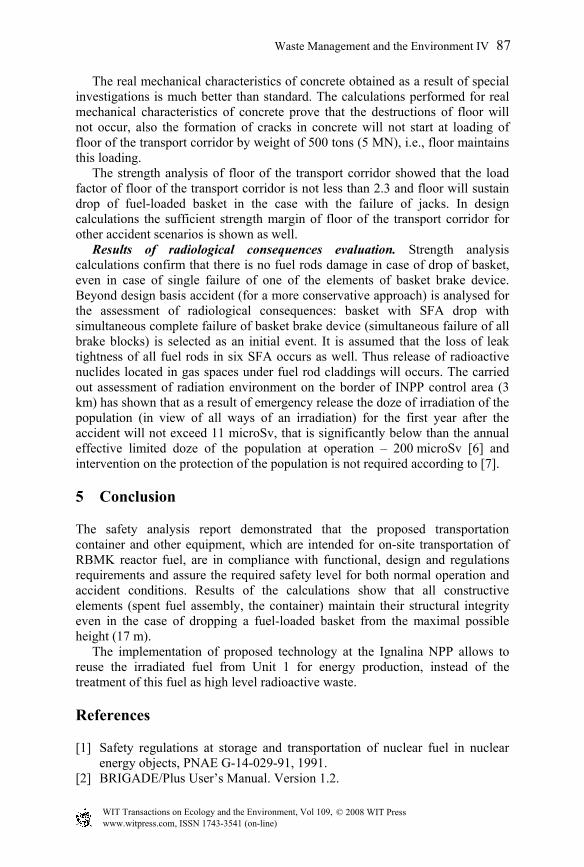
The real mechanical characteristics of concrete obtained as a result of special investigations is much better than standard. The calculations performed for real mechanical characteristics of concrete prove that the destructions of floor will not occur, also the formation of cracks in concrete will not start at loading of floor of the transport corridor by weight of 500 tons (5 MN), i.e., floor maintains this loading. The strength analysis of floor of the transport corridor showed that the load factor of floor of the transport corridor is not less than 2.3 and floor will sustain drop of fuel-loaded basket in the case with the failure of jacks. In design calculations the sufficient strength margin of floor of the transport corridor for other accident scenarios is shown as well. Results of radiological consequences evaluation. Strength analysis calculations confirm that there is no fuel rods damage in case of drop of basket, even in case of single failure of one of the elements of basket brake device. Beyond design basis accident (for a more conservative approach) is analysed for the assessment of radiological consequences: basket with SFA drop with simultaneous complete failure of basket brake device (simultaneous failure of all brake blocks) is selected as an initial event. It is assumed that the loss of leak tightness of all fuel rods in six SFA occurs as well. Thus release of radioactive nuclides located in gas spaces under fuel rod claddings will occurs. The carried out assessment of radiation environment on the border of INPP control area (3 km) has shown that as a result of emergency release the doze of irradiation of the population (in view of all ways of an irradiation) for the first year after the accident will not exceed 11 microSv, that is significantly below than the annual effective limited doze of the population at operation – 200 microSv [6] and intervention on the protection of the population is not required according to [7].
5 Conclusion
The safety analysis report demonstrated that the proposed transportation container and other equipment, which are intended for on-site transportation of RBMK reactor fuel, are in compliance with functional, design and regulations requirements and assure the required safety level for both normal operation and accident conditions. Results of the calculations show that all constructive elements (spent fuel assembly, the container) maintain their structural integrity even in the case of dropping a fuel-loaded basket from the maximal possible height (17 m). The implementation of proposed technology at the Ignalina NPP allows to reuse the irradiated fuel from Unit 1 for energy production, instead of the treatment of this fuel as high level radioactive waste.
References
[1] Safety regulations at storage and transportation of nuclear fuel in nuclear energy objects, PNAE G-14-029-91, 1991.
[2] BRIGADE/Plus User’s Manual. Version 1.2.
www.witpress.com, ISSN 1743-3541 (on-line)
© 2008 WIT PressWIT Transactions on Ecology and the Environment, Vol 109,
Waste Management and the Environment IV 87

[3] ABAQUS/Explicit User’s Manual Volume IV, Version 6.4, 2003. [4] Algor Finite Element Analysis System. ALGOR Instruction Manuals. Algor,
Inc. Pittsburgh, 2000. [5] Dundulis, G., Narvydas E., Uspuras E., Listopadskis N., Confinement Study
Using Algor and Neptune Codes, Transactions of 15th International Conference on Structural Mechanics in Reactor Technology, Seoul, Korea, VI, 333, 1999.
[6] Hygiene Standard. Radiation Protection in nuclear facilities, HN 87-2001, Vilnius, 2002.
[7] Hygiene Standard. Basic standards of radiation protection, HN 73-2001. Vilnius, 2001.
www.witpress.com, ISSN 1743-3541 (on-line)
© 2008 WIT PressWIT Transactions on Ecology and the Environment, Vol 109,
88 Waste Management and the Environment IV