engine coordination actionengine.brgm.fr/documents/engine_bestpracticehandbook.pdf · engine...
TRANSCRIPT

ENGINE Coordination Action (ENhanced Geothermal
Innovative Network for Europe)
BEST PRACTICE HANDBOOK
for the development of Unconventional Geothermal Resources
with a focus on
ENHANCED GEOTHERMAL SYSTEM
In bibliography, this document will be referenced as:
ENGINE Coordination Action. Best Practice Handbook for the development of Unconventionnal Geothermal Ressources with a focus on Enhanced Geothermal System. 2008. Orleans, BRGM Editions. Collection Actes/Proceedings. ISBN 978-2-7159-2482-6. ISSN 1773-6161. Available at: [http://engine.brgm.fr/Documents/ENGINE_BestPracticeHandbook.pdf] (January 25, 2010)


Best Practice Handbook ENGINE Coordination Action (ENhanced Geothermal Innovative Network for Europe)
3
Summary
Executive summary .....................................................................................................................9
Introduction ................................................................................................................................11
1. Site Investigation ..................................................................................................................13
1.1. GENERAL INTRODUCTION ..........................................................................................13
1.2. SITE SCREENING: DOWNSCALING WORKFLOW......................................................15
1.2.1. Continental scale approach ...............................................................................19
1.2.1.1. Definition of interesting regions............................................................ 19 1.2.1.2. Construction of European mechanical structure.................................. 20 1.2.1.3. Neotectonics (seismic history) ............................................................. 21
1.2.2. Regional scale (e.g. Rhine Graben, Pannonian basin)......................................23
1.2.2.1. Broad-scale Geophysical studies......................................................... 23 1.2.2.2. Remote sensing ................................................................................... 26
1.2.3. Local scale (e.g. typical 50 km x 50 km)............................................................26
1.2.3.1. Geochemistry....................................................................................... 26 1.2.3.2. Intermediate-scale Geophysical studies .............................................. 26 1.2.3.3. Resource potential ............................................................................... 28 1.2.3.4. Cross-checking with other economic factors ....................................... 28
1.2.4. Reservoir scale (e.g. typical 2 km x 2 km) .........................................................29
1.2.4.1. 3-D geology - field geology .................................................................. 29 1.2.4.2. Well investigation and fine-scale geophysics ...................................... 30 1.2.4.3. Geochemistry and geothermometers .................................................. 32 1.2.4.4. Local stresses and reservoir geomechanics........................................ 33 1.2.4.5. Conceptual model and reservoir modelling ......................................... 34
1.3. WORKFLOW EXAMPLES IN DIFFERENT GEO-ENVIRONMENTS.............................34
1.3.1. Volcanic environment.........................................................................................35
1.3.1.1. Iceland.................................................................................................. 35 1.3.1.2. Guadeloupe, France ............................................................................ 36 1.3.1.3. Kamchatka, Russia .............................................................................. 37 1.3.1.4. Vesuvius, Italy ...................................................................................... 37
1.3.2. Crystalline or Metamorphic environment ...........................................................38
1.3.2.1. Soultz-sous-Forêts, France.................................................................. 38 1.3.2.2. Larderello, Italy..................................................................................... 39

Best Practice Handbook ENGINE Coordination Action (ENhanced Geothermal Innovative Network for Europe)
4
1.3.3. Sedimentary environment.................................................................................. 40
1.3.3.1. Groß Schönebeck, Germany................................................................40 1.3.3.2. Altheim, Austria ....................................................................................41
1.3.4. Critical overview of workflow processes............................................................ 42
1.4. FROM THE STATE OF THE ART TOWARD THE FUTURE......................................... 44
1.4.1. Goals of exploration........................................................................................... 45
1.4.1.1. Characterization of host rock conditions ..............................................45 1.4.1.2. Integrate data .......................................................................................48 1.4.1.3. Improve imaging between wells ...........................................................49
1.4.2. Concluding remarks........................................................................................... 50
2. Drilling, reservoir assesment and Monitoring ................................................................... 51
2.1. DRILLING ....................................................................................................................... 51
2.1.1. Drilling sediments - Gross Schönebeck ............................................................ 51
2.1.2. Drilling volcanics - Iceland ................................................................................. 53
2.1.3. Drilling granites - Soultz..................................................................................... 57
2.1.4. Drilling metamorphics - Larderello & Philippines............................................... 58
2.2. STIMULATION................................................................................................................ 59
2.2.1. Hydraulic stimulation ......................................................................................... 59
2.2.1.1. Hydraulic stimulation - sediments - Gross Schönebeck.......................60 2.2.1.2. Hydraulic stimulation - volcanics - Gross Schönebeck ........................62 2.2.1.3. Hydraulic stimulation - Granites - Soultz ..............................................62 2.2.1.4. Hydraulic stimulation - Metamorphics - Larderello ...............................62
2.2.2. Thermal stimulation ........................................................................................... 63
2.2.3. Chemical stimulation ......................................................................................... 63
2.3. TESTING ........................................................................................................................ 65
2.3.1. Hydraulic testing ................................................................................................ 65
2.3.2. Tracer testing..................................................................................................... 67
2.4. RESERVOIR ASSESSMENT MANAGEMENT AND MONITORING............................. 68
2.4.1. Reservoir assessment ....................................................................................... 69
2.4.2. Reservoir management ..................................................................................... 70
2.4.3. Corrosion and scaling........................................................................................ 70
2.4.4. Reservoir monitoring ......................................................................................... 71
3. Exploitation: Best Practices and innovation Needs ......................................................... 73

Best Practice Handbook ENGINE Coordination Action (ENhanced Geothermal Innovative Network for Europe)
5
3.1. OVERVIEW .....................................................................................................................73
3.2. EXPLOITATION CYCLE .................................................................................................74
3.2.1. Piping .................................................................................................................75
3.2.2. Production pumps ..............................................................................................75
3.2.3. Reinjection pumps..............................................................................................75
3.2.4. Heat exchangers ................................................................................................76
3.2.5. Inhibitors injecting equipment ............................................................................77
3.3. POWER GENERATION..................................................................................................77
3.3.1. Condensing Plants .............................................................................................77
3.3.2. Binary Plants ......................................................................................................78
3.3.3. Heating applications...........................................................................................80
3.4. MONITORING AND FIELD MANAGEMENT ..................................................................80
3.5. RESEARCH AND DEVELOPMENT NEEDS..................................................................81
4. Environmental and socioeconomic impact........................................................................83
4.1. ENVIRONMENTAL CONCERNS....................................................................................83
4.1.1. Introduction ........................................................................................................83
4.1.2. Low Enthalpy Hydrothermal Fields ....................................................................83
4.1.3. High Enthalpy Hydrothermal Fields ...................................................................84
4.1.4. Enhanced Geothermal Systems ........................................................................86
4.2. SOCIAL ASPECTS .........................................................................................................88
4.3. INNOVATION NEEDS.....................................................................................................90
Authors........................................................................................................................................91
References ..................................................................................................................................93

Best Practice Handbook ENGINE Coordination Action (ENhanced Geothermal Innovative Network for Europe)
6
List of Figures Figure 1 - Site selection benefits vary considerably (see criteria) from taking into
account key information and knowledge available on regional, local and reservoir scales and using a multidisciplinary approach in data compilation, acquisition, interpretation, modelling and validation. The approach incorporates innovative concepts from both academia and industry relevant for the development of conventional and unconventional geothermal resources. ..................................................................................................................... 15
Figure 2 - Definition of the multi-tiered workflow approach. This approach proposes a methodology for selecting an adequate site for geothermal investigations, based on the use and execution of different tools, models and analyses. The scale dependant approach allows definition of several sizes of potential areas, from the reservoir size to the geological region. ................................. 18
Figure 3 - Seismic velocity anomalies from tomography ΔVP, S (left) and conversion of velocities to temperature (blue=500°C; red=1300°C). The high temperature zones at 100 km depth derived from P waves correspond to areas with mantle plumes (e.g. Eifel area and French Massif Central) and lithosphere extension in postorogenic collapse and /back-arc extension (e.g. Western Mediterranean, Aegean, Pannonian Basin) (Goes et al., 2000) ............................................................................................................................. 19
Figure 4 - Section Amsterdam-Basel and Section D of strength reconstruction of the European foreland of the Alps, showing a clearly stratified rheology strongly controlled by crustal structure and deep lithospheric thermal structure (Cloetingh et al., 2005).................................................................................................. 21
Figure 5 - Stress map of Europe, displaying present-day orientation of the maximum horizontal stress. Different symbols stand for different stress indicators. The length of symbols represents the data quality. Background shading indicates topographic elevation (Heidbach, 2004)........................................................ 22
Figure 6 - Map of Europe with superimposed distribution of seismicity (red dots), illustrating present-day active intraplate deformation (Cloetingh et al., 2005). ............................................................................................................................ 24
Figure 7 - Downhole motor (Moineau - Motor) for directional drilling (A. Sperber). ...................... 54
Figure 8 - A typical large-diameter HT-well in Iceland (S. Thorhallsson). ..................................... 56
Figure 9 - Typical gel proppant treatment during stimulation operations at the Groß Schönebeck well Gt GrSk 4/05 A (G. Zimmermann). ................................................... 61
Figure 10 - Installation of a pumping unit for injection of chemical compounds at Coso geothermal field (photo P. Rose, EGI, Univ. of Utah). .................................................. 64
Figure 11 - Injection Test after stimulation of the Soultz well GPK2 (T. Tischner).......................... 67
Figure 12 - View of injection pumping system at Berlin Geothermal field, in El Salvador............... 76
Figure 13 - Flow chart of a single flash condensing geothermal power plant. ................................ 78
Figure 14 - Flow chart of a double flash condensing geothermal power plant................................ 78
Figure 15 - Schematic presentation of a geothermal water cooled ORC power plant. ................... 79

Best Practice Handbook ENGINE Coordination Action (ENhanced Geothermal Innovative Network for Europe)
7
List of Tables Table 1 - Investigations performed at the Bouillante site (Volcanic environment)...........................36
Table 2 - Investigations performed at the Soultz site (Crystalline environment). ............................39
Table 3 - Investigations performed at Larderello. ............................................................................40
Table 4 - Investigations performed at Gross Schönebeck...............................................................41
Table 5 - Investigations lead and results obtained at Altheim. ........................................................42
Table 6 - Results of HCl-HF treatments for scaling removal and connectivity development in high temperature geothermal wells. ........................................................65
Table 7 - Geothermal Systems Overview ........................................................................................74
Table 8 - Comparison of CO2 emissions between geothermal and conventional power plants. ...............................................................................................................................84


Best Practice Handbook ENGINE Coordination Action (ENhanced innovative Network for Europe
9
Executive summary The ENGINE work has been synthesized in a Best Practice Handbook presenting an overview of the investigation, exploration, and exploitation of unconventional geothermal reservoirs (UGR) and Enhanced Geothermal Systems (EGS) taking into account economic and socio-environmental impacts.
The Best Practice Handbook is designed for different groups of interest such as engineers, politicians, and decision makers from industry. The entire EGS life cycle is covered in four chapters:
Chapter 1: Site investigation
This chapter addresses the best practices for locating of a geothermal site. A scale-dependent workflow has been developed for this purpose describing a step-by-step procedure on how to locate a reservoir using different techniques. It introduces different tools and approaches to investigate resources from continental to regional, as well as local and reservoir scales (Figure 2). This method is implemented into workflow examples applied to various geo-environments depending on the geological context of the site: sediments, volcanics, granites and metamorphics. Taking into account sites in Iceland, France, Russia, Italy, Germany and Austria, a critical overview of the workflow processes is presented. This first chapter ends with prospective considerations about mapping parameters, integrating data, and improving imaging between wells.
Chapter 2: Drilling, stimulation and reservoir assessment
Drilling operations are performed in order to access geothermal reservoirs for energy exploitation. This chapter describes various topics, ranging from drilling of wells to reservoir preparation for exploitation. Drilling techniques are synthesised from the experience acquired on various geothermal sites in Germany, Iceland, France, Italy and the Philippines. They are specifically presented using the geological context classification introduced in the first chapter (sediments, volcanics, granites and metamorphics). Next, the hydraulic, thermal and chemical stimulations are detailed keeping the same geological context classification. Then, testing tools for characterising hydraulic connection between wells are described. The final part of the chapter establishes the state-of-the-art and proposes good practices for reservoir assessment, management and monitoring.
Chapter 3: Exploitation
Considering the economical context, the exploitation chapter presents plant configurations and technologies for power production and heat supply before making R&D proposals. It develops a critical analysis of the geothermal exploitation options from classical condensing power generation to binary units and co-generation plants. The first part of this chapter discusses the key factors for choosing between the possible options and provides important economic considerations. Best practices for technology including fluid supply and power generation (e.g. thermodynamical cycles), are presented in the second part. The chapter concludes with a description on ways to fill the gaps for reducing exploitation costs and improving EGS economics.

Best Practice Handbook ENGINE Coordination Action (ENhanced Geothermal Innovative Network for Europe)
10
Chapter 4: Environmental and socioeconomic impact
The last chapter of the Best Practice Handbook examines how environmental impacts need to be carefully assessed and how geothermal energy project(s) will benefit the environment and local development. This chapter introduces the main benefits offered by geothermal energy, such as emission reduction, local environmental protection and community development. The second part describes the practices needed to minimize environmental impacts linked to geothermal installation of Low Enthalpy Hydrothermal Fields, High Enthalpy Hydrothermal Fields and Enhanced Geothermal Systems. Finally the public acceptance is addressed both at the general scale through education, training and governmental regulations and at the site scale to develop the geothermal project(s) in harmony with the local population.

Best Practice Handbook ENGINE Coordination Action (ENhanced Geothermal Innovative Network for Europe)
11
Introduction The BEST PRACTICE HANDBOOK (BPH) presents an overview of the investigation, exploration, and exploitation of unconventional geothermal reservoirs (UGR) and Enhanced Geothermal Systems (EGS), taking into account economic and socio-environmental impacts. This BHP is designed for different groups of interest such as engineers, politicians, and decision makers from industry. In contrast to the conventional high-temperature steam reservoirs in volcanic environments, EGS resources and UGR are more difficult to localise and to assess. While volcanic resources are clearly indicated by obvious effects at the surface (e.g. geysers, fumaroles, etc.), unconventional and EGS resources commonly have indirect traces (e.g. increased surface heat flow). Usually, they are water-dominated systems and characterised by a wide range of production temperatures. The lower temperature limit in unconventional reservoirs is defined by the current technical limitations in conversion of heat into electric energy. An EGS is defined by improvement of the natural resource.


Best Practice Handbook ENGINE Coordination Action (ENhanced innovative Network for Europe
13
1. Site Investigation
1.1. GENERAL INTRODUCTION
Site Investigation covers the initial phase of an unconventional project. It provides an investigation scheme for possible EGS resources and reservoirs and includes a validation of appropriate exploration techniques in different geo-environments. The Site Investigation methodology is treated in chapter 1.2: Site Screening, which describes the best practice for the localization of a geothermal site. A scale-dependent workflow has been developed for this purpose. It describes a step-by-step procedure, how to locate a reservoir using different, and geoscientific techniques. It introduces different tools and approaches to investigate resources on a continental scale. While downscaling to regional and local scales, tools and approaches are adopted to the respective scale and the information of interest on the specific scale. A second chapter is dedicated to the evaluation of the different methods described in the first chapter. This is realised through the description of investigation examples in different geo-environments. Then, examples for validating the techniques applied so far are described in the section on Analogue Sites. Special emphasis is given to the enhancement of the hydraulic conditions of the later reservoir and performance assessment during production governed by the development of thermal, hydraulic, and chemical conditions in the later reservoir.
Geothermal energy in EGS is assessed using geothermal brine as carrier fluid in a number of wells for production and re-injection. In particular, the number and depth of wells strongly influences the financial planning. The energy is usually utilized in a doublet system with a production and re-injection well (Landau, Gross Schönebeck, Unterhaching, etc.). Energetically more complex systems are developed using two or more wells; for example, a triplet system in Soultz or an economically optimised multiple-well system (Vörös et al., 2007), as existing in Larderello, Travale, and Mt. Amiata. The current high drilling costs, however, prevent a wide use of multiple well systems.
The high financial investment for well drilling goes along with a high risk of identifying a non-productive reservoir in which production flow rates and temperatures obtained are not economically viable. The workflow in the chapter Site Screening has been developed to provide a best practice procedure offering an evaluation of the efficiency of individual tools in different geological environments in order to minimize this risk. Other challenges in EGS and UGR exploration are also described. Excluding accident risks during drilling of boreholes, the risk of occurrence of positive magnitude seismic events during hydraulic stimulation must be carefully taken into account, as public acceptance can be considered as a key factor of achievement of unconventional geothermal reservoir assessment.
Site investigation requires clearly defining conditions and criteria for a productive and sustainable EGS/UGR utilization. Geothermal production is defined from the relation:
[ ] ( )REINJPRODfPTHERM TTcQP −⋅⋅= ρ
with PTHERM the produced thermal power; TPROD the production temperature, TREINJ the reinjection temperature, [ ]fPcρ the heat capacity of fluid (approx. 4.2 106 [J m-3 K-1] for a liquid-
phase reservoir), and Q the flow rate [m3 s-1]. The relation illustrates that the thermal productivity of a plant increases linearly with the two key factors: temperature and flow rate. Therefore, the herein presented EGS/UGR site investigation is based on the following criteria:

Best Practice Handbook ENGINE Coordination Action (ENhanced Geothermal Innovative Network for Europe)
14
1. Flow rate:
In a specific geo-environment with a given reservoir temperature, the productivity of a geothermal system is increased by higher flow rates. The dominant factor is subsurface permeability that can vary in a broad range from < 10-18 m2 up to > 10-12 m2. Large reservoir permeabilities commonly yield natural convection patterns that influence the heat distribution in the subsurface. Permeability can be controlled by fractures or by matrix porosity. Generally, the natural permeability is increased by various stimulation techniques (see Chapter 2). In geothermal systems, typical operation flow rates can vary between 10 kg s-1 up to > 100 kg s-1. From an economic perspective reasonable flow rates (> 50 kg s-1) have to be targeted for EGS systems. Besides technical constraints, high flow rates will dramatically increase the power required for pumping in low permeable reservoirs. Prospection for potential geothermal systems should therefore focus preferentially on areas with high natural permeability.
2. Temperature:
The temperature field in major parts of Europe increases generally by 20°C to 30°C per km depth. At specific locations in active tectonic areas, however, temperature gradients above 100 K km-1 can be met. The thermal field can become a critical factor for economic viable geothermal system, since it determines the necessary drilling depth for a given target temperature. In view of the fact that drilling costs increase non-linearly with depth, shallower EGS systems tend to be more lucrative (see Chapter 4). The target production temperature needs to reflect the present state of conversion technology in the Organic Rankine Cycle (ORC) (lower limit around 85°C) and of Kalina technology (lower limit around 100°C).
3. Stress field
The stress field is generally defined by the value of three stress components (one vertical and two horizontal ones) and by orientation of the maximal horizontal stress. The stress regime is defined by the relative magnitudes of vertical and horizontal components of the stress tensor:
- σv<σh<σH: compressional regime (reverse faulting);
- σh< σv<σH: transcurrent regime (strike-slip faulting);
- σh<σH<σv: extensional regime (normal faulting).
σv, σh and σH being respectively the vertical, minimum and maximum horizontal stress components.
Shearing is favoured by a large difference between minimum and maximum stresses. The direction of σmax defines the orientation of the main fractures. Stress regime variation patterns can be identified from a continental to a very local scale. Indeed, stress field evaluation and importance will be treated in several sections of this handbook. At reservoir scale, the stress regime defines the failure conditions of the rock mass. This, in turn defines for the creation of flow paths, a very important factor for reservoir exploitation. The local stress can also be linked with the mean orientation of fractures within and near the reservoir; the well orientation (in the case of drilling a deviated well) should be defined according to local stress, in order to maximize the probability of crossing important fractures, allowing large water inflows. Stress field characterization will be treated in section 0.
4. Secondary key factors:
There are several other crucial factors that determine the longevity of a geothermal system. If the system cools down too rapidly, existing flow paths may be clogged by chemical

Best Practice Handbook ENGINE Coordination Action (ENhanced Geothermal Innovative Network for Europe)
15
precipitation or scaling in the geothermal loop, thus destroying the technical infrastructure. Therefore, beginning in the investigation phase, possibilities of reservoir extension or fluid chemistry should be included in the considerations. Economic sustainability of geothermal production depends strongly on the reservoir characteristics and the selected drilling operations.
1.2. SITE SCREENING: DOWNSCALING WORKFLOW
The major challenges in site screening are:
- Identification of areas of relatively high geothermal potential on continental and regional scale;
- Delineation of economically viable reservoirs at local scales.
The two scales are addressed using information provided by different geoscientific fields, which are summarized in Figure 1. On a continental and regional scale, the geothermal potential is investigated by geodynamical approaches using parameter evaluation of lithosphere strength, stress field, heat flow, etc. More applied geoscientific methods are used to investigate the reservoir on a finer scale. Regional and local resource analyses integrate the continental knowledge in localized studies of a discrete assessable area.
Continental Regional Local/Concessional Reservoir
Lithosphere Strength
Seismic tomography
Geology, Hydrogeology
Airborne Magnetics, Surface Geophysics (gravimetric, EM, Seismic)
Resource analysis
Hydraulic properties
Borehole Geophysics (Borehole Imaging, VSP,...)
Heat Flow
Moho Depth
Geochemistry, fluid geochemistry
Petrography, Petrophysics, Mineralogy
Stress Field and Structural Analysis
Figure 1 - Site selection benefits vary considerably (see criteria) from taking into account key information and knowledge available on regional, local and reservoir scales and using a multidisciplinary approach in
data compilation, acquisition, interpretation, modelling and validation. The approach incorporates innovative concepts from both academia and industry relevant for the development of conventional and
unconventional geothermal resources.

Best Practice Handbook ENGINE Coordination Action (ENhanced Geothermal Innovative Network for Europe)
16
The existence of an economically viable geothermal reservoir results from multi-scale physical processes. In order to present a realistic and comprehensive overview of the different processes herein involved and the way to investigate them, a multi-tiered approach is proposed in the following chapter. It also presents the major advantage of allowing different entry levels as mentioned in the introduction.
Four different scales are defined on the basis of political, geological and technical/economical parameters:
- Continental scale: area of common energy policy;
- Regional scale: a region defined by a set of common geological characteristics;
- Local scale (typically 50 km x 50 km): an intermediate area of economical interest, which allows down-scaling from regional to a technically assessable scale;
- Reservoir scale (typical 2 km x 2 km): a geothermal reservoir defined as a hot rock volume that is likely to host injected or produced fluids.
The scale dependent approach is presented as a workflow. This scheme provides a step-by-step procedure to localize an economically viable resource or reservoir. In the workflow presented for each scale, methods and tools are proposed in order to answer the following questions, linked with the major challenges of site screening: is there a chance to find an economically viable reservoir in this region/continent? Is the risk of finding a non-productive reservoir acceptable (on finer scales)?
The workflow includes a brief description of each suggested method or tool at the four different scales. The following points are developed:
- Which geo-environment can this method/tool be applied to?
- How does this method / tool / model / analysis contribute to the task? To which conclusion can it lead us? Which user level is the beneficiary of the investigation?
- Are these results trustworthy? The question of the degree of confidence that we can have for each method is, though very hard to estimate, a key factor.
- In which direction should research efforts be made in order to improve results and confidence in results?
As some of the methods exposed in the multi-tiered approach can be applied to different scale levels (essentially geophysical methods), short definitions are proposed here, in order to avoid repetition at each scale.
Seismology
Seismology aims at studying earthquakes and propagation of induced seismic waves. It is of great interest in geothermal exploration because, among others, it allows locating the hypocenters of earthquakes, delineating faults, identifying focal mechanisms and imaging the deep structure of the earth. It is closely linked with the determination of stress field.
Seismic tomography
Seismic tomography involves estimating and acquiring information concerning the velocity and attenuation of seismic waves, generated either by natural or induced seismic events or man-made sources. Velocity and attenuation depend on various factors (type of the medium, density, fluid and gas saturation...) that can be linked to potential geothermal reservoirs.

Best Practice Handbook ENGINE Coordination Action (ENhanced Geothermal Innovative Network for Europe)
17
Seismic refraction
Seismic refraction involves measuring the travel time of seismic waves generated by a surface source (hammer, explosives...) that travel down to a layer of different acoustic impedance, are refracted along the top of the layer and return to the surface. Seismic refraction gives mainly information about 2-D distribution of velocity with depth.
Seismic reflection
Seismic reflection is based on the interpretation of two-way travel time of seismic waves generated by a surface source (hammer, explosives, vibroseis...) that are reflected at the interface of two layers of difference acoustic impedance. Seismic reflection gives mainly information about 2-D and 3-D distribution of reflectors with depth. Important data treatment is needed in order to identify and interpret results. Costs of seismic reflection are higher than seismic refraction, but the vertical resolution obtained is generally better.
Direct Current (DC) electric method
DC method is actually a group of controlled-source electric methods characterized by quasi-direct electric current injection in the earth from grounded electrodes. The electrical field in the earth is generated by current flowing between two pairs of electrode (injection and receiver) fed by batteries or some form of current generator. Interpretation of the measured equipotential lines or surfaces enables mapping of electric resistivity heterogeneities in 2-D or 3-D.
Transient ElectroMagnetic (TEM) method
TEM is a group of controlled-source electric and EM methods characterized by using time varying currents induced in the earth by the current loops lying at the earth surface or by other dipole-like sources. The interpretation of the electromagnetic field measured at the surface is typically used for mapping near-surface or deep structures.
Airborne EM (electromagnetic) method
This group of controlled-source EM methods (differing from each other by the hardware configuration used) is characterized by mounting part or all of the standard electromagnetic profiling systems on an aircraft. The objective of the airborne EM survey is to carry out electromagnetic profiling rapidly (especially in the large areas in regions where access on the ground is difficult). Interpretation of the anomalies detected in the earth enables mapping electrical resistivity differences between rock units.
Magnetotelluric method
The magnetotelluric method is a natural source EM method based on electromagnetic induction in the earth by ionospheric or magnetospheric currents. Interpretation of the electrical and magnetic fields measured at the earth surface in the range of periods enables 2-D and 3-D mapping of resistivity structures and is especially useful for exploration of deep geothermal targets.
Gravimetry
As the gravitational field of the earth depends on the density of the rocks, variations of the gravitational field (Bouguer anomalies) observed at the surface or in a borehole are due to density changes in the subsurface, which can be interpreted in terms of changes in the composition and/or geometry of the geological layers.

Best Practice Handbook ENGINE Coordination Action (ENhanced Geothermal Innovative Network for Europe)
18
Magnetism and aeromagnetism
Measurements of the static magnetic field (ground or airborne) are used to map anomalies that can be used for determining the Curie temperature depth (i.e. the temperature above which rocks lose their characteristic ferromagnetic ability). This depth is generally inversely correlated with heat flow. At large scale (> 500 by 500 km), this method can be used when high-quality heat flow measurements are not available globally or when they are not uniformly distributed or when they are contaminated by local thermal anomalies.
Remote sensing
Remote sensing is the general name of techniques used for measuring physical properties of a remote object or phenomenon. In general, we measure the electromagnetic radiation emitted from a remotely sensed object.
Continental scale approach OBJECTIVE: Qualitative overview of the geothermal potential in a continent
Definition of interesting Regions Thermo-mechanical crustal models Neotectonics
Regional scale (e.g. Rhine Graben, Pannonian basin) OBJECTIVE: Quantification and mapping of the geothermal potential in a
geological region Broad scale Geophysics studies Remote sensing
Local scale (e.g. typical 50 km x 50 km) OBJECTIVE: Site location of an exploration well
Geochemistry Intermediate scale Geophysics studies Resource potential Cross-checking with other economic factors
Reservoir scale (e.g. typical 2 km x 2 km) OBJECTIVE: Site location of further wells
3-D geology Well investigation and fine-scale geophysics Geochemistry and geothermometers Local stress Conceptual model and reservoir modelling
Figure 2 - Definition of the multi-tiered workflow approach. This approach proposes a methodology for selecting an adequate site for geothermal investigations, based on the use and execution of different tools, models and analyses. The scale dependant approach allows definition of several sizes of potential areas,
from the reservoir size to the geological region.

Best Practice Handbook ENGINE Coordination Action (ENhanced Geothermal Innovative Network for Europe)
19
1.2.1. Continental scale approach
OBJECTIVE: Qualitative overview of the geothermal potential in a continent
1.2.1.1. Definition of interesting regions EGS are preferentially planned in areas with high temperatures at depths of 3 km – 6 km. Until now areas have been selected largely on the basis of observations of high temperature gradients near the surface (e.g. volcanic areas such as Iceland) and/or relative high temperatures assessed in deep boreholes drilled mainly for hydrocarbon exploration and production (e.g. Gross Schönebeck, Landau, Soultz).
For assessing the exploration potential of continental regions for geothermal energy we need to look beyond depths of temperatures known from shallow wells and require capabilities to predict temperatures at depth in areas where no well control is available.
Thermal characteristics of lithosphere beyond well control
Predicting the temperature of the Earth at depths beyond existing well control and in areas where no well data is available has been a prime topic in Earth science for centuries. Tectonic models integrating geological and geophysical databases in a process-oriented approach provides a continent-wide assessment of first order temperature prediction of the lithosphere. In these models the lithosphere constitutes a mechanically strong topmost layer of the Earth, which is c.a. 100-200 km thick and floats on the asthenosphere, which behaves –on geological times-scales as a fluid. The base of the lithosphere is marked by a relatively constant temperature of around 1330°C (Figure 3).
Figure 3 - Seismic velocity anomalies from tomography ΔVP, S (left) and conversion of velocities to temperature (blue=500°C; red=1300°C). The high temperature zones at 100 km depth derived from P
waves correspond to areas with mantle plumes (e.g. Eifel area and French Massif Central) and lithosphere extension in postorogenic collapse and /back-arc extension (e.g. Western Mediterranean, Aegean,
Pannonian Basin) (Goes et al., 2000).

Best Practice Handbook ENGINE Coordination Action (ENhanced Geothermal Innovative Network for Europe)
20
The actual temperatures extrapolated at depth are sensitive to surface heat flow, and thermal parameters of the rocks (thermal conductivity and heat production essentially) (Clauser, 2006). Knowledge of rock conductivity is generally based on extrapolation from laboratory experiments, taking into account mineralogical, pressure, temperature and porosity effects.
Continental-scale transient effects
Tectonically induced continental deformation is most pronounced at the boundaries of plates, e.g. spreading ridges or subduction zones. However, plate boundary forces are transmitted far into to the continental interior resulting in intraplate deformation. This deformation is reflected by extension or compression of the interiors of the lithosphere (Ziegler et al., 1998), which can have a significant effect on predicted heat flow and temperature.
The passive stretching model (McKenzie, 1978) was one of the first tectonic model delivering a quantitative assessment of kinematic extension of the lithosphere in relation to the sedimentary infilling history of basins. Tectonic models show that extension can be accompanied or preceded by a period of deep lithospheric thermal upwelling, related to mantle plumes. This upwelling, and associated magmatic activity results in a significant increase of heat flow. Examples in Europe include portions of the Rhine Graben, the Eifel area (Germany) and the Massif Central (France).
Lithospheric compression typically results in crustal thickening and mountain building. The lithospheric thickening results in relatively low heat flows. However, elevated mountains can be actively eroded in fault bounded zones, resulting in elevated heat flows close to the surface. Exhumation with elevated heat flows can also occur in lithospheric extension in particular on rift flanks of extensional basins.
The Earth is marked by a multistage deformational history in which extension can occur over areas that have been previously marked by a compressional orogeny with significant mountain building. Extension over such areas can result in thinning and minimizing thermal attenuation of the crust in absence of significant sediment infill and loss of heat production in the crust. Consequently, the heat flow can be strongly elevated. Areas in Europe include the Western Mediterranean (Italy), the Pannonian Basin, and the eastern Aegean. In these areas, active deep mantle processes may partly enhance the terrestrial heat flows.
1.2.1.2. Construction of European mechanical structure The temperatures in the crust and mantle lithosphere can be used to calculate the rheology of the lithosphere, which is used as a parameter in finite element tectonic models of the stress-strain distribution in the lithosphere. The strength of continental lithosphere is controlled by its depth-dependent rheological structure in which the thickness and composition of the crust, the thickness of the mantle–lithosphere, the potential temperature of the asthenosphere, the presence or absence of fluids, and strain rates play a dominant role.
The strength of the European lithosphere typically shows a stratification into a brittle upper crustal, ductile lower crust and strong ductile upper mantle (Figure 4). The layered rheology is clearly reflected in the way stress is transmitted from the plate boundaries into the European continent resulting in upper crustal extensional and strike-slip faulting and complex stress and strain interactions around the Mediterranean. The stress-strain interactions can be modelled in more detail by crustal and lithospheric scale thermo-mechanical deformation models that can be validated by stress measurements, observed seismicity (magnitude, stress tensor), and neotectonic deformation. These models provide first order information on active deformation

Best Practice Handbook ENGINE Coordination Action (ENhanced Geothermal Innovative Network for Europe)
21
mechanisms, the active tectonic stress field driving fracturing and deformation and its relation to (induced) seismicity.
Figure 4 - Section Amsterdam-Basel and Section D of strength reconstruction of the European foreland of the Alps, showing a clearly stratified rheology strongly controlled by crustal structure and deep lithospheric
thermal structure (Cloetingh et al., 2005).
1.2.1.3. Neotectonics (seismic history) The term neotectonics refers to the youngest and recent tectonic processes and tectonic regime in an area. The tectonic regime can be extensional, compressional, strike-slip, or combination of strike-slip with either extensional or compressional style, depending on the state of stress. (See section 0) The stress results in deformation of the crust, which manifests itself in horizontal and vertical motions. These motions occur along faults and/or folds. From the viewpoint of the identification of EGS and location of exploratory wells, fracture and fault systems are of primary importance as they are potential water conduits. In the north-western Great Basin the geothermal fields lie in belts of intersecting, overlapping, and terminating faults, in many cases of Quaternary age (Faulds et al., 2006).
Active faults are more promising targets compared to older inactive faults, as recent or subrecent motion along the faults may provide sufficient permeability for water flow. In case of extensional stress and tectonic regime the faults are more likely open than in case of compressional tectonics. Therefore, the most important features of neotectonics relevant to research of EGS and UGR, as well as site location of exploration wells, are the accurate identification of active faults and the state of stress and tectonic regime.
The regional stress field in Europe (Figure 5) is based on data obtained by hydraulic fracturing, borehole break-outs and fault planes solutions of earthquakes. Local faults and weak zones may disturb the regional stress field and change the direction and type of the stress regime. At the beginning of the exploration phase we must assume that the regional stress field prevails. It may be better defined after the drilling and analysis of the first borehole (See section 1.2.4.4.)

Best Practice Handbook ENGINE Coordination Action (ENhanced Geothermal Innovative Network for Europe)
22
Figure 5 - Stress map of Europe, displaying present-day orientation of the maximum horizontal stress. Different symbols stand for different stress indicators. The length of symbols represents the data quality.
Background shading indicates topographic elevation (Heidbach, 2004).
Location of active faults is not a simple task, because deep rooted faults can splay to smaller branches near the surface. These may be discontinuous, and the surface manifestations could be weak. Earthquake hypocenter determinations can have a few kilometres of error, or earthquakes can occur along different segments of the fault system. Therefore, hypocenters indicate only the approximate width of the fault zone. Integration of all available geological and geophysical data is necessary to identify recently active faults: remote sensing, digital terrain models, structural analyses, geophysical methods such as reflection seismology, including vertical seismic profiles.
Active faults are often seismogenic. Seismicity in the study area indicates that the Earth's crust is close to failure, a state that is referred to as being critically stressed. If permeability of the reservoir rock is then increased by hydraulic stimulation, a small increase in the well head pressure results in (re)-opening of fractures. In areas hosting hydrothermal fluids rich in gas content (magmatic origin) gas geochemistry may help recognizing active fault by mapping natural gas discharge from the ground.

Best Practice Handbook ENGINE Coordination Action (ENhanced Geothermal Innovative Network for Europe)
23
1.2.2. Regional scale (e.g. Rhine Graben, Pannonian basin)
OBJECTIVE: Quantification and mapping of the geothermal potential in a geological region
1.2.2.1. Broad-scale Geophysical studies From a regional point of view, the main target of large-scale geophysical investigation is to provide constraints regarding the temperature distribution at depth and the tectonic setting. Different constraints can be provided by several methods.
Broad-scale gravimetry
This method provides primary information regarding density distribution at depth, which may be attributed to subsurface structure and temperature distribution. The long-wavelength gravity anomalies reflect large-scale structural heterogeneities of the lithosphere, which can be related to its thermal regime. The regional relatively short-wavelength components (L <100 km – 400 km) correlate with specific tectonic structures, which in turn may be related to geothermal conditions. Where regional seismic reflection and tomography data are available, it is possible to separate the effect on gravity of Moho depth variations and density variations within the crust and mantle. Where broad-scale density distribution is available, and the effect of shallow formations can be subtracted, it is possible to define anomalous areas that could possibly be related to favourable geothermal conditions.
Heat-flow and temperature gradient analysis
One of the basic methods to outline prospective areas for geothermal research is the analysis of terrestrial heat flow density (or terrestrial heat flow), which defines the amount of heat flowing across a unit surface area during a time unit. It is expressed as the product of the thermal conductivity of rocks and the temperature gradient. The temperature gradient gives the rate of increase of temperature with depth. Assuming that the heat is transported only by conduction, the temperature at any depth (relevant for exploration) can be calculated using the temperature gradient (Haenel et al., 1988). Accordingly, areas characterized by high heat flow and low thermal conductivities resulting in a large temperature increase with depth should be the most favourable sites for geothermal research.
These methods have been intensively used in order to define temperature distribution down to a depth of several kilometres. Since the 1980s, much effort has been devoted to the investigation of the thermal field in Europe culminating in regional mapping projects, such as the ‘Geothermal Atlas of Europe’ (Working Group "Geothermal Atlas of Europe" of the International Heat Flow Commission, 1992) and the ‘Atlas of Geothermal Resources in Europe’ (Hurter and Haenel, 2002). These maps form a broad base to assess Europe’s thermal field on a regional scale. They are based on information from many boreholes, whereby a great portion of these data stem from the exploration for hydrocarbons. Using these data, stored in national databases and updated whenever new data become available, assessments of the thermal potential have been made at regional scales throughout Europe. These data represent the first reference when developing new geothermal prospects.
However, heat flow is influenced by numerous phenomena and processes such as the spatial variation of thermal conductivity and heat production due to different rock types, sedimentation and erosion, groundwater flow, volcanism, etc. In such cases the heat flow and the temperature gradient vary with depth and the prediction of temperature at great depth is carried out by numerical modelling (see section 0). Most of these processes act on a local scale (e.g.

Best Practice Handbook ENGINE Coordination Action (ENhanced Geothermal Innovative Network for Europe)
24
groundwater flow) and less on a regional scale (e.g. erosion). On continental and regional scales the assumption of conductive heat transport is a good approximation. Therefore, the average heat flow describes well the underground temperature conditions. On the continental scale, the average heat flow depends partly on the last profound tectonic event (Artemieva et al., 2006). Modelling of tectonic events provides a general framework to explain the average heat flow of a region and predict temperatures on lithospheric depth scale. The heat flow is an important input or control parameter in these models.
Seismic methods
Seismology provides a measure of mechanical properties and parameters in the lithosphere. Earthquake foci and focal mechanisms are reasonably good indicators of stress orientation and distribution. These data, integrated with wellbore and geological data provide information regarding stress distribution and tectonic features (Figure 6). Seismic tomography is particularly suitable for defining the seismic velocity distribution at depth. Geometry is hardly recognized, but velocity anomalies can be clearly defined both in the crust and in the mantle. Tomography is used to locate the lithosphere-asthenosphere boundary and calculate the temperature distribution.
Figure 6 - Map of Europe with superimposed distribution of seismicity (red dots), illustrating present-day active intraplate deformation (Cloetingh et al., 2005).
Deep crustal reflection and refraction seismic data are now available thanks to numerous crustal projects collected in the last few decades in Europe. They are used to define the geometry of the crustal interfaces and the P-wave velocity distribution, as well as the Moho depth. The interpretation of deep crustal and lithospheric temperatures from seismic tomography data, deep seismic reflection and refraction and/or receiver function studies and

Best Practice Handbook ENGINE Coordination Action (ENhanced Geothermal Innovative Network for Europe)
25
gravity data requires careful tectonic interpretation and integrated lithospheric process models. The interpreted deep lithosphere and crustal temperatures reveal at some points a strong correlation with the measured surface heat-flow pattern. This is best reflected in areas of great lithosphere thickness (e.g. the Precambrian and Caledonian terranes), which show relatively lower heat flow and temperature at drillable depth than areas with lithospheric thinning. Active tectonic settings can result in strong dynamic effects of crustal and lithospheric heat flow, which can help predict and understand regional patterns in heat flow, constraining exploration assumptions.
However, of less global significance, but usually of great importance to the temperatures in a particular area, are relative shallow (< 10 km) static and dynamic phenomena such as (1) magma intrusions into high crustal levels (e.g., Larderello); (2) thermal conductivity variations, both vertical and horizontal as they occur in sedimentary basins; (3) large- and small-scale fluid flow (e.g. the Rhine Valley); and (4) radiogenic sources in the upper crust (e.g. Cornwall). The scale of control on temperatures by these global- and regional-scale processes is variable, and many examples now are available to quantify these effects.
Electromagnetic prospection
Geothermal resources, especially when liquid phase is involved, are ideal targets for electromagnetic (EM) methods since they produce strong variations in underground electrical resistivity. Properties such as temperature, porosity, permeability, fluid salinity, partial melt fraction and viscosity, many of which may take an important role in defining a geothermal system, affect electrical resistivity and often produce strong variations. Since rheology is profoundly affected by temperature and the presence of fluids, low electrical resistivity may be an indication of rheologically weak zones in the lithosphere within which deformation can concentrate. Moreover, active deformation greatly influences fluid interconnectivity, so that low resistivity also may represent the state of the deformation itself. Electrical resistivity models may offer an image of fluid generation during active crustal thickening and of its transport toward the surface in major zones of crustal weakness (Wannamaker et al., 2002). In addition to rheological investigation, resistivity distribution at various depths may show the location of possible enhanced fluid concentration and the presence of still molten intrusions. On the other hand, resistivity should be always considered with care. Experience has shown that the correlation between low resistivity and fluid concentration is not always correct since alteration minerals produce comparable, and often a greater reduction in resistivity. Moreover, although water-dominated geothermal systems have an associated low resistivity signature, the opposite is not true, and the analysis requires the inclusion of geological and, possibly, other geophysical data, in order to limit the uncertainties.
Among EM methods only magnetotelluric (MT) may provide the suitable investigation depth for regional characterization. Disadvantages of the MT method are its low geometrical resolution (though lateral resolution may be improved when using short site spacing) and noise (both geological and industrial) sensitivity.
Aeromagnetics
Airborne magnetic anomalies can be used for determining the Curie temperature depth (i.e. the temperature above which rocks lose their ferromagnetic properties). This depth is generally inversely correlated with heat flow.
At the broad scale (> 500 km by 500 km), this method can be used where high-quality heat flow measurements are not available globally, where they are not uniformly distributed, or where they are contaminated by local thermal anomalies. The method is based on the analysis of the power density spectrum of the magnetic anomalies (Ross et al., 2006).

Best Practice Handbook ENGINE Coordination Action (ENhanced Geothermal Innovative Network for Europe)
26
1.2.2.2. Remote sensing One possible method in the search and detection of special geological features (e.g. faults and other structural features) controlling the existence of a potential geothermal site is the use of satellite images. The Landsat-1 satellite (originally ERTS – Earth Resources Technological Satellite, 1972) was dedicated to this task. The MSS instrument made a multi-spectral image of the land surface. It recorded the reflected solar radiation of the surface elements in the visible and in the near-infrared wavelength region. This made possible to classify different rock types on these images. In less vegetated, arid and semi-arid regions different soil or rock type and soil water content can be classified on these satellite images. However, EGS or URG reservoirs are generally characterized by the absence of geothermal manifestations on the surface. That means that satellite information is generally poorly adapted to EGS reconnaissance.
Satellites and infrared sensors can also be used to determine the temperature of the Earth’s surface (wavelength is temperature dependant). Thermal anomalies in moderate climate areas can be identified using air photos or high-resolution satellite images of snowy conditions. The melting, wet snow has less reflectance than cold and dry snow. These melting and molten surfaces can be identified on these images as dark spots indicating higher temperature, which may result from geothermal activity.
1.2.3. Local scale (e.g. typical 50 km x 50 km)
OBJECTIVE: Site location of an exploration well
1.2.3.1. Geochemistry The main purpose of geochemical surveys is to predict subsurface temperatures and to obtain knowledge of the origin and flow directions of the geothermal fluid. The basic philosophy behind this type of prospecting is that geothermal fluids on the surface reflect physical, chemical and thermal conditions at depth.
Access to the geothermal fluids and to the surrounding rocks is needed in order to analyse them. Except for particular geothermal environments where geothermal fluids reach the surface and where spatial variations of the lithologies may be limited (e.g. Iceland), it is necessary to have a well drilled in the reservoir in order to perform geochemical analysis. Thus, the geochemical aspects of thermal reservoirs will be treated in section 0. However, the geochemical composition of fluids sampled from natural springs surrounding a targeted geothermal area is generally a rather good indicator of in situ conditions.
1.2.3.2. Intermediate-scale Geophysical studies At reservoir scale, the use of high-resolution geophysical tools is generally required in order to elucidate the spatial variation of rock parameters that can be coupled with temperature distribution and productivity of wells drilled for a geothermal exploitation of the subsurface (e.g. density, wave velocity, electrical resistivity).
Seismic methods
Seismic imaging (2-D/3-D seismic reflection and refraction) is the most common exploration tool to be used. Advanced methodologies initially developed for oil exploration are available: Amplitude Versus Offset (AVO) and Amplitude Variation with Azimuth and offset (AVAZ). Seismic methods enable detection of the stratigraphy of an area and provide good geometrical

Best Practice Handbook ENGINE Coordination Action (ENhanced Geothermal Innovative Network for Europe)
27
resolution of the main lithological units. Sophisticated algorithms and methods have improved resolution and accuracy of imaging.
However, seismic imaging, while a powerful geological mapping tool, does not always lead to a significant improvement in understanding the nature and composition of the deep structure of complicated geothermal systems. Other disadvantages of seismic methods are their weak response from permeable zones and high cost. Moreover, in Western Europe, many potential EGS sites are located in basement rocks overlain by sediments. That means that seismic methods can be very helpful but only for deriving a good image of the structure above the EGS target. In this way, fault geometry visible in the sediments can be extrapolated downward into the top of crystalline rocks.
Electromagnetic methods (Magneto telluric - MT, Direct Current – DC, Transient Electromagnetic – TEM)
Thanks to improved methodology and software, EM methods are now very affordable in terms of costs and field logistics.
Investigation depth of MT is much greater at long source periods compared to most controlled-source EM methods like TEM which are usually unable to detect geothermal reservoirs deeper than 1-2 km (Demissie, 2005). Of the various geophysical methods, the MT technique was found to be the most effective in defining a conductive reservoir overlain by a more conductive clay cap. MT sounding of volcanic geothermal areas enables detection the location of the geothermal reservoir beneath the volcanic sediments. Thus, MT imaging of geothermal zones provides information on the base of the conductive clay cap and spatial location of the anomalously low resistivity zones, which could be considered as candidates for being the geothermal reservoir. TEM data are also often used in order to reduce the negative effect of the near-surface geological noise on the results of MT soundings (Romo et al., 2000).
It is important to mention that even though the resistivity anomalies are controlled mainly by faults, the resistivity variations do not necessarily reflect the formational boundary nor the lithological differences of the rocks mapped in the area. Another problem associated with finding the fluid circulation zones by EM methods is that the correlation between low resistivity and fluid volume is not always correct, because alteration minerals produce comparable and often a greater reduction in resistivity. Moreover, although fluid circulation has an associated low resistivity signature, the opposite is not true. Therefore, low resistivity anomalies are not always suitable as geothermal targets. However, if they are accompanied by low-density and/or low seismic velocity anomalies, this may increase the probability of such a conclusion. So, integration with geological, other geophysical and drilling data may help to eliminate undesirable low resistivity targets from consideration.
Gravimetry
Gravity data provide important information at a local scale when added to other data. Taking into account the anomalous geothermal gradient present in the area and attributing reasonable densities to the lower crust, upper mantle, and major rock types in the area, the density distribution in the upper crust can be defined through modelling and attributed to the various formations and to the elements of the geothermal systems, e.g. intrusions and reservoirs.
Gravity data are particularly effective for determining location and depth of vertical and sub-vertical density contrasts. These density contrasts can be, for example, limits of sedimentary basins, vertical or sub-vertical faults (steps), boundaries of bodies with different porosity. It also allows the determination of the shape of sedimentary basins where the density contrast is

Best Practice Handbook ENGINE Coordination Action (ENhanced Geothermal Innovative Network for Europe)
28
strong enough (> 50 kg·m3). Gravity methods can also help to eliminate, constrain, or select structural hypotheses.
Aeromagnetic
The airborne magnetic method is the most powerful and cheap method for determining the depth to magnetic basement. Results are very similar to those obtained with gravimetry, but only apply for crystalline units; it is possible to obtain information about the presence or absence of vertical and subvertical faults, or to define limits of basins relative to surrounding crystalline basement. Combinations between magnetic and gravity data provide generally valuable information about EGS basement structures and batholith shape.
1.2.3.3. Resource potential The resource potential evaluation is a key method that provides useful information concerning the possible location of exploration boreholes. It is based on the integration of the global geological knowledge available in the region. The first step of the work consists of collecting geological data (from well, geological cross section and geophysical interpretation essentially), hydrogeological data (hydraulic conductivities of different layers derived from well tests) and thermal data (estimation of thermal conductivities of layers, mean surface temperature and borehole temperature logs). Then, temperature of the identified aquifers can be computed through 3-D numerical models calibrated on borehole measurements, and the geothermal potential of such target horizons can be calculated, with respect to available hydrogeological data.
The entire heat (EHIP for heat in place) of the ground cannot be extracted and used. The utilisable energy Eut is defined by the integration over a time period �t of the power produced by a doublet at a constant flow rate. This energy can be only indirectly calculated, as the flow rate used for the calculation depends on the hydraulic properties of the aquifer, and as the produced temperature depends on its depth and geographic location. The Recovery factor R is defined by the ratio between Eut and EHIP.
From that point, two different approaches to quantify Eut can be used. The first approach is a direct approach, which consists in calculating the recovery factor directly (Paschen et al., 2003; Tester et al., 2006). The second indirect approach, is based on the calculation of possible energy production with a doublet system in a considered aquifer (Signorelli and Kohl, 2006). Depending on the characteristics and class of the aquifer, resulting recovery factors are estimated between 1.5 % and 40 %.
The resource potential analysis allows quantification of the total amount of energy that can be extracted from underground and definition of geographical zones and depths where the potential of a geothermal reservoir would be the greatest.
1.2.3.4. Cross-checking with other economic factors In the case of electric power production from geothermal energy in EGS, residual heat is available after the conversion process. It is essential for economical viability of the plant to give value to this heat. There are two types of residual heat occurring as by-product in the conversion process:
- The residual thermal energy stored in the geothermal brine after heat exchange in the binary cycle (Tmax≈75°C): Heat at this temperature level is suitable for district heating in high-density

Best Practice Handbook ENGINE Coordination Action (ENhanced Geothermal Innovative Network for Europe)
29
areas, hot water supply, and low-temperature industrial processes (e.g. food industry and textile industry).
- The residual heat of the condensed binary liquid after conversion in the turbine (Tmax=35°C): in particular, the agricultural sector offers possible utilisation of heat with temperatures <35°C (e.g. greenhouses, aquaculture technology).
Cross-checking with areas of energy demand depends strongly on the technical possibilities as mentioned above, but also on the economic framework. The evaluation of the energy demand covers the present-day situation of the main economic and technical constraints of a possible geothermal site:
- Balance of production costs and price of electric energy for the site, including the technical constraints of input of the electric power in a local or regional electric net.
- Comparison of the costs and prices of electric power generation with the balance for heat production only.
- Possibilities of electric power generation and utilisation of residual heat with the aim of a complete identification of the present potential heat consumers and the development of a cascade system for heat utilization.
1.2.4. Reservoir scale (e.g. typical 2 km x 2 km)
OBJECTIVE: Site location of further wells
1.2.4.1. 3-D geology - field geology
Local field scale analysis
For EGS reservoirs developed in fractured rocks, study of the fracture system is done by combining several methods at local scale. The geometry of pre-existing fractures or faults must be mapped by different techniques or field measurements (structural mapping, gas in soils, field outcrops analysis). Generally, fractures and small scale faults have a great impact on the reservoir behaviour and fluid flow under initial and changed stress conditions. However small scale structures are rarely detectable since they are in the subseismic region. Geomechanical models integrating data from outcrop analogs and fracture statistics help to quantify and understand fault and fracture systems. The main geological interfaces are then identified such as the contact between the sediments and the basement. In volcanic context, the volcano-tectonic structures must be mapped. They correspond to the alignment of recent volcanoes generally related to a deep heat source (magma chamber, intrusions). Radiogenic dating is also a useful technique to determine the most recent volcanic centre or hydrothermal activity. The mapping of different surface hydrothermal manifestations (thermal springs, fumaroles, hot soils, altered soils, sinter, and/or travertine) is also a valuable method for targeting a geothermal well.
Outcrop scale analysis
In order to estimate the fracture organisation (type, density, orientation) and to determine the mineralogical composition of the reservoir rocks, local outcrop analyses are necessary. Then, fine-scale fracture geometry is investigated as well as the internal structure of larger fault zones by detailed geological mapping. Petrographic, mineralogic and hydrothermal alteration studies are robust methods for fully characterizing the subsurface geothermal deposit.

Best Practice Handbook ENGINE Coordination Action (ENhanced Geothermal Innovative Network for Europe)
30
Well scale analysis
Based on various well data (cuttings, cores, geophysical logs, borehole image logs), substantial information can be obtained about the reservoir composition and the reservoir structure (see section 1.2.4.2). In volcanic, granitic or metamorphic environments, examination of cuttings permits delineation of a geological profile of the geothermal wells in terms of massive rocks and hydrothermally altered and fractured zones. In a sedimentary environment, geological well studies are similar to petroleum reconnaissance. Core study gives access to more detailed and precise geological information such as rock texture, rock petrography, fracture type and fracture content (filling). Moreover, detailed mineralogical and petrophysical investigations can be done in order to determine the nature of the hydrothermal alteration and derive some physical properties (porosity; bulk density). Comparison between rocks and cutting is a valuable way for calibrating well logs. Fractures and faults are evaluated with depth based on borehole image logs and core studies. Then, the location, size and orientation of the fractures intersecting the wells are fully characterized by borehole imaging techniques. Classic geophysical logs allow locating facies variations and the main geological interfaces (lithological contact, faults, dikes…) in the wells.
1.2.4.2. Well investigation and fine-scale geophysics Several tools are available in order to increase information about the reservoir from the well.
Temperature log
The aim of temperature logging is to provide direct information about the temperature in a borehole. However, drilling and drilling fluid circulation alter the original temperature by cooling the bottom of the borehole and heating the upper part of the borehole. In the case of deep boreholes the decay of the disturbances takes a few months. In general, it is not possible to wait for the steady state due to economic reasons. The original formation temperatures can be corrected from repeated temperature logs measured during the recovery period (Horner, 1951). Undisturbed temperature profiles provide information concerning heat transport near the borehole.
The temperature log is interpreted together with all available geophysical, hydrological and geological data. One of the routine methods is the calculation of interval heat flows. The lithology along the borehole is known from core samples, cuttings, and gamma ray and resistivity logs. The thermal conductivity of rocks is estimated based on the lithology, and using the thermal conductivity and the temperature gradient (measured or) derived from the temperature log, the heat flow is calculated. Heat flow variations with depth may indicate groundwater flow.
The most precise interpretation of temperature logs is possible by 3-D numerical modelling of heat transport, where the geometry of different rocks, their thermal conductivity, heat production, and hydraulic conductivity are taken into account (see section 0). The most important fitting parameter in these models is the temperature log. 3-D modelling of temperature also increases reliability of the temperature extrapolation to greater depth.
Temperature logs are also important tools to monitor the reservoir during exploitation. The first temperature log, which reflects the natural conditions in the reservoir and around it, is used as a reference. Temperature logs may also give information about the phase of fluid in the reservoir. E.g. the temperature-depth curves in high enthalpy reservoirs in natural conditions in Iceland follow the boiling point curve, indicating that the fissures contain hot water (Asmundsson, 2007).

Best Practice Handbook ENGINE Coordination Action (ENhanced Geothermal Innovative Network for Europe)
31
Temperature measurements are also good indicators for locating drilling fluid losses or entry points of formation fluids into the borehole. These locations are marked by rapid temperature changes. Gas release into the borehole is indicated by a temperature drop. Temperature logs are also applied to check the quality of cementing behind the casing.
Vertical seismic profile
As the reflection surface seismic method is hardly able to image subsurface structures within the crystalline basement, the borehole seismic techniques constitute an attractive way to collect spatial information about the major and potentially permeable structures in the vicinity of the geothermal wells drilled in fractured basement rocks. Vertical Seismic Profiling (VSP) permits acquisition of an inter-well image of the deep-seated rock beyond the borehole wall. The main permeable major faults can be imaged and localised by the VSP method. Moreover, VSP data allow a better constraint of the velocity model, useful for reflection and refraction interpretation. 3-D geophysics and VSP are not routinely used in geothermal exploration, due to higher costs. However, recent 3-D geophysical results and VSP acquisition on the Soultz site provides encouraging results about the location of major faults intersecting the wells. In the oil industry, this method constitutes the first step for targeting new wells in both sedimentary basins and in fractured oil-field reservoirs in basement rocks, and the same should be done for geothermal exploration.
Borehole imaging and sonic log
Borehole acoustic imaging tools provide essential information concerning the fractures intersecting boreholes. Orientation and damage zone thickness of faults and fractures can be derived from such acoustic logs. Local variations of the fracture orientations can also give important information on the variations of the stress field orientation (see section 0). A sonic log allows estimating variations in porosity along the borehole. Borehole electrical image logs are also a very valuable method for characterizing the fracture system and the present-day stress field in EGS.
Borehole gravimetry
The borehole gravimetry, BHGM, is a simple large-penetration logging tool. Applications include detection of fluids and gas-filled porosity, and detection and definition of remote structure.
One of the great advantages of the BHGM as a density logging tool is that it is practically unaffected by near-hole influences like casing, poor cement bounding, hole roughness, washout, etc. Another advantage is the simplicity of the relationship between gravity, mass, rock volume, and density.
The BHGM measurements sample a large volume of rock, which provides a density porosity value that is more representative of the formation. This is especially beneficial in fractured reservoirs. The wide radius of investigation is also successfully used to determine gas-fluid contacts in reservoirs where other measurements are ineffective.
Gamma ray logs
Gamma ray logs provide valuable information about the natural radioactivity and the various lithologies penetrated by the well. Spectral gamma ray gives continuous variations of uranium, thorium, and potassium contents, which, combined with density, allows calculation of heat production of the rock mass. In granitic context, litho logy variations as well as hydrothermal alteration can be evidenced from these logs.

Best Practice Handbook ENGINE Coordination Action (ENhanced Geothermal Innovative Network for Europe)
32
Resistivity log
Resistivity logs provide information about the electric conductivity of the rock. Resistivity is expressed in Ohm·m. It is sensitive to the type of rock and to the amount of water in the rock mass (depending on the porosity). Other factors also influence the resistivity, such as temperature and composition of the formation fluid. Therefore, the correlation between temperature, porosity and resistivity is not straightforward. In spite of this, contrasts observed in resistivity logs, cross-checked with other well data can provide information concerning the ability of the media to constitute an economical and accessible geothermal reservoir.
1.2.4.3. Geochemistry and geothermometers Global studies of hydrothermal processes showed that specific properties of the underground fluid composition are closely related with the geothermal conditions of their formation. Therefore, studying of these properties provides information about the thermal state at depth that complements the results of direct thermometry and serves as a basis for forecasting the deep geothermal conditions in little explored regions.
It was experimentally established that temperature and concentration of some characteristic species (the so-called geothermometers) are related. Using empirical or semi-empirical formulas, one can estimate the “base depth” temperature from the known amount or proportion of these components in areas of surface manifestations of thermal activity. In practice, geological, geochemical or geophysical geothermometers are used usually for this purpose. Several geothermometers can be distinguished:
- Hydrochemical geothermometers: The most important hydrochemical thermometers are based on the dissolved silica content, atomic and ion Na/K and Na/Li ratios, and Na, К and Са concentration proportions (Kharaka and R.H., 1989). The use of these parameters is based on two main assumptions: 1) the water-rock system within the zone of hydrothermal formation is in equilibrium, and 2) absence of precipitation-dissolution of the given component along the path of water migration from the heating zone (thermal supply) to the sampling point. Readings of these thermometers depend on many factors including temperature, pressure, hydrothermal flow speed, mineralogical conditions, partial pressure of gases, pH of the medium and others. One of the most widespread chemical geothermometers is based on silica. This is due to the fact that the solubility of silica contained in the solution as Si(ОН)4 molecules depends strongly on temperature and weakly on the content of other ions within a wide pH range. Usually, silica is depositing quite slowly. Estimates calculated from Si-geothermometers reflect the temperature in deepest parts of hydrothermal systems. Experience in Iceland shows that geothermal waters equilibrate with chalcedony (very fine quartz crystals) below 180°C and with quartz at higher temperatures.
- Gas geothermometers: Gas geothermometers are based on equilibrium chemical reactions between gaseous species. For each reaction considered, a thermodynamic equilibrium constant may be written, where the concentration of each species is represented by its partial pressure in the vapour phase. The concentrations (or ratios) of gases like CO2, H2S, H2, N2, NH3, and CH4 are controlled by temperature (Arnorsson and Gunnlaugsson, 1985). As such, these data are used to study a correlation between the relative gas concentrations and the temperature of the reservoir. The gas-gas equilibrium in geothermal fields with two phase-components should not reflect the real gas composition present in the reservoir. It depends on many factors, including the gas/steam ratio. No re-equilibration of chemical species from the source or sources to wellhead is assumed. Application of geothermometric techniques based on thermodynamic equilibrium of organic gases is a

Best Practice Handbook ENGINE Coordination Action (ENhanced Geothermal Innovative Network for Europe)
33
reliable tool to evaluate the temperature of deep systems even by adopting the hydrocarbon composition of natural discharges.
- Mineral geothermometers: Stability of the alteration mineral assemblages in different temperature ranges is used for indirect temperature estimation at depth. An empirical relationship between formation temperature and the occurrence of specific alteration minerals is used to determine a proper depth for the production casing. This method offers currently the best estimation of aquifer production temperature that can be made during drilling. Mixed-layer clay geothermometers have proved useful in the study of many hydrothermal systems around the world (Harvey and Browne, 1991). Although they have proved most effective in sediments or tuff sequences, they may not provide correct results in fracture-dominated geothermal reservoirs, because incomplete water-rock interaction away from major flow paths may invalidate their use.
- Isotopic geothermometers: In isotopic geothermometry the δD, δ18O, δCO213C, δCH4
13C, 3Не/4Не quantities are used. In particular, studies showed that the ratio 3Не/4Не in underground fluids is a stable regional marker: it remains virtually the same within the given region for different type fluids, but differs considerably from region to region, thus reflecting their tectonic characteristics. Regional 3Не/4Нe variations in the Earth's gases generally agree with heat flow variations. The established empirical dependency between these parameters (Polyak and Tolstikhin, 1985) allows a rough heat flow estimation from the isotopic-helium ratio.
- Electromagnetic geothermometers: The electrical conductivity of rocks is primarily related to rock composition but is also a function of temperature. This dependence permits its use as an electromagnetic geothermometer. If wells with known temperature profiles are available, an indirect estimation of the spatial temperature distribution from surface magnetotelluric measurements may be possible (Spichak et al., 2007b). However, complex inhomogeneous structures often met in geothermal areas only allow construction of coarse temperature models. Such cases require multiple assumptions regarding the mechanisms of electrical conductance. Using an EM geothermometer in homogeneous rocks could enable temperature extrapolation to depths 2-3 times exceeding the depth of the well.
1.2.4.4. Local stresses and reservoir geomechanics Characterisation of the in-situ stress field is mainly done by determining the orientation and the magnitude of the maximum principal stresses. Where no information on stress magnitudes is available stress models can be developed assuming that in situ stress magnitudes in the crust will not exceed the condition of frictional sliding on well-oriented faults.
Commonly, geometrical constraints (fault throw and fault intersections) in mapped 3D fault pattern (from seismic surveys) indicate a limited variation of stress regimes (Zoback, 2006). A comprehensive review of stress characterisation has been achieved for engineered geothermal systems (Evans et al., 1999). Depth profiles of the orientation of the horizontal principal stress axes and the magnitude of minimum horizontal stress can be obtained by different methods with a sufficient accuracy. Several methods are used that permit derivation of the stress field. Stress measurement can be essentially achieved by overcoring and hydraulic fracturing. Based on borehole samples, overcoring allows calculating the magnitude and directions of the stresses existing in hard rocks. Borehole hydrofracturing is also used to measure the minimum horizontal stress and the orientation of the maximum horizontal stress. For example, the HTPF (hydraulic testing of pre-existing fractures) method provides a mean of determining the complete stress tensor (Cornet and Valette, 1984). From borehole data, such as an acoustic borehole televiewer, electrical image tools, and caliper logs, it is possible to analyse vertically induced fractures, ovalisation processes, borehole breakouts, en echelon fractures, or more generally

Best Practice Handbook ENGINE Coordination Action (ENhanced Geothermal Innovative Network for Europe)
34
borehole instabilities. In cases of inclined wells the rotation of borehole-near stress tensor need to be considered in analysing artificial fractures. As such tools have their system of inclinometry, the orientation of principal stresses can be deduced. The stress field can also be deduced at a more regional scale from focal mechanism solution of earthquakes.
If the in situ stress field is known, geomechanical reservoir models define local stress perturbations along faults and in compartment blocks. The slip-tendency analysis (Morris et al. 1996) helps to understand the fault behaviour under changed stress conditions while drilling and stimulation. Wellbore stability and fault reactivation potential can be quantified by geomechanical approaches.
1.2.4.5. Conceptual model and reservoir modelling A conceptual model of the reservoir takes into account as much available information as possible. Geological and geophysical data (well and field scale) as well as geochemical results can be integrated into a conceptual model of the reservoir. Indeed, it is a logical synthesis of the different results obtained by investigation and experiments realised on the site.
Reservoir modelling is a key tool that can help monitoring and optimising performance of an EGS system. Numerical modelling is a very broad branch of actual scientific research in the domain of geothermal energy. Great progress has been made these last few decades. Several computer codes are now available in Europe, based on different numerical scheme (finite difference, elements or volumes), using various spatial discretisation methods (structured or unstructured mesh) (Kohl et al., 2007). Many couplings are possible, and models can definitely help understand the physical processes occurring in the reservoir. It is important to note that reservoir modelling can help define the conceptual model. Simple reservoir models can be built in order to test assumptions of the conceptual model or in order to validate or falsify the conceptual model on which it is based.
The conceptual model helps to determine the viability of the reservoir for exploitation and the extent of needed further investigations.
1.3. WORKFLOW EXAMPLES IN DIFFERENT GEO-ENVIRONMENTS
Analogue sites are defined by a set of common features with the geo-environment of a selected site. Examples for analogue sites are outcrops (e.g. to observe mechanical features such as fracture distribution), representative geothermal sites (e.g. Soultz or Gross Schönebeck), or test sites (e.g. Grimsel nuclear waste test site or CO2 sequestration sites). Concerning the representative geothermal sites, three groups are distinguished:
- Volcanic environment;
- Crystalline environment;
- Sedimentary environment.
In the following, for each experimental site, the approach used for geothermal exploration is explained or summarized in a table. Iceland is considered as a unique experimental site due to the homogeneity of geothermal conditions over the entire Island.

Best Practice Handbook ENGINE Coordination Action (ENhanced Geothermal Innovative Network for Europe)
35
1.3.1. Volcanic environment
1.3.1.1. Iceland Iceland is a sub-aerial part of the ocean floor, located where the central axis of the Mid-Atlantic Ridge intersects the Iceland hot-spot, resulting in abnormal crustal thickness and complicated tectonic patterns. The half-spreading rate is close to 1cm/yr. The ridge axis crosses the island from southwest to northeast forming a volcanic rift zone characterized by many active central volcanoes and associated high-temperature geothermal fields (T>200°C at 1 km depth). The rift zone is highly faulted, and the uppermost 1 km is composed of permeable young basaltic material. Outside of the volcanic zone the crust typically consists of altered basaltic lavas of low primary permeability due to secondary mineralization. However, recent tectonic activity, probably due to glacial rebound and relative movement of the ridge axis and the hot spot, has formed permeable fractures that are pathways for geothermal fluids and result in numerous low-to-medium temperature geothermal fields ( T< 150°C at 1 km depth). The background heat flow in Iceland varies with age from 70 mW·m-2 to 250 mW·m-2, and the oceanic crustal thickness varies from 20 km to nearly 40 km.
Geothermal exploration is done with a multidisciplinary approach where geological mapping, geochemistry and geophysics interact. Geological mapping (essentially tectonic structure, but also stratigraphy, hydrothermal alteration and eruption history) and geochemistry (if hot springs or fumaroles exist) are widely used. Concerning geophysical studies, resistivity soundings, mainly based on TEM (0 km – 1 km) and MT (1 km – 15 km) measurements play a key role. In high temperature fields the resistivity reflects foremost the thermal alteration that depends on the temperature in the reservoir. A high resistivity core overlain by a low resistivity cap reflects a body with temperatures exceeding 250°C provided there is equilibrium between temperature and thermal alteration at present. A second low resistivity layer at depths 3 km – 15 km may reveal up-flow of the geothermal fluid into the reservoir or shallow magma chambers.
Analysis of natural seismic events may reveal active fracture zones within the crust and hence potential up-flow zones. Magma chambers are detectible by S-wave shadows or high Vp/Vs ratios. An important parameter to estimate the temperature conditions in the proposed unconventional part of the systems is to map the maximum depth of earthquakes within the system. This is done by local seismic networks. The maximum focal depth is most likely controlled by the temperature. Usually, earthquakes do not occur under a depth where temperature is in the range 650°C – 850°C. Thus by combination of seismic data, resistivity data, and temperature logs from boreholes in the conventional part of the system, constraints can be set for the possible supercritical depth range.
Aeromagnetic and gravity surveys are also helpful, the former reflecting the extent of intensive hydrothermal alteration, the latter showing density anomalies like intrusions or in-filling of calderas.
The exploratory work leads to a conceptual model of the geothermal field. Based on that, the wells are sited. During the exploratory drilling phase borehole geology supported by geophysical well logging are the main tasks, which together with results from well testing make the basis for a revised geological and hydrological model of the reservoir.
During exploitation geo-scientific research is still important to understand the response of the geothermal reservoir to production. This includes monitoring of temperature, pressure, induced seismicity, as well as changes in fluid chemistry. Geodesy and gravity methods are used to monitor the mass reduction from the reservoir and may also detect eventual formation of steam

Best Practice Handbook ENGINE Coordination Action (ENhanced Geothermal Innovative Network for Europe)
36
caps that might be a good target for production but also may form potentially hazardous areas due to steam explosion danger.
1.3.1.2. Guadeloupe, France The Bouillante field is located along the coast of western Guadeloupe within the volcanic Caribbean islands. This hydrothermal system is related to the occurrence of recent active volcanoes. The Bouillante field is currently exploited for electricity generation as a conventional high enthalpy system with reservoir temperature around 250°C – 260°C. Reservoir characterisation in the Bouillante field of Guadeloupe is based on four old wells drilled in the 70’s and three recent wells drilled in 2001. Four of these wells are producers and presently, only three of them feed the two plants (4.5 MWe and 11 MWe). Permeability is primarily controlled by faulting within the basement composed of submarine volcanic formations. The geothermal fluid is a NaCl brine with a 20g/L TDS (Total Dissolved Solid) and has a mixed origin between meteoric water and seawater.
The exploration field work done at the scale of the reservoir in the Bouillante field are mainly geology (structural analysis, hydrothermal alteration) hydrogeochemistry (geochemical composition of thermal springs, gas in soils), and geophysics. Different geophysical methods have been applied around the Bouillante geothermal field: off shore, high-resolution reflection seismic, magnetic and bathymetric surveys and, onshore, 2-D electrical resistivity imaging, magnetic, gravimetry and broad band seismology surveys (Fabriol et al., 2005). Off-shore seismic reflection data provide additional structural information between off shore and inland areas mainly in terms of fracture/fault geometry. Magnetic data show structural features and potential altered zones related to the geothermal field. 2-D electric resistivity measurements crossing producing wells show good correlation with the vertical zoning of hydrothermal alteration in the wells. 3-D geological modelling integrating well data and surface geological information was done in order to visualise the main geological interfaces and faults as well as for estimating the reservoir volume and petrophysics. Erreur ! Source du renvoi introuvable. details the experiments realised in the Bouillante geothermal site. Hydraulical and thermal modelling integrating tracer results are currently in progress.
Table 1 - Investigations performed at the Bouillante site (Volcanic environment).
I. Investigations
Ground Temperatures
Temperature Gradient in wells
Structural analysis
Geochemistry Thermal springs, gas
II. Fluid/Rock interactions Fluid Studies Hydrothermal
alteration
III. Geophysics Geophysics Off shore On shore
IV. Reservoir Engineering
Production tests
Thermal Stimulation
Tracer experiment

Best Practice Handbook ENGINE Coordination Action (ENhanced Geothermal Innovative Network for Europe)
37
1.3.1.3. Kamchatka, Russia
The Mutnovsky geothermal system is located approximately 75 km south of the city of Petropavlovsk-Kamchatsky, close to the northern foothills of Mutnovsky volcano, at an elevation of 800 m – 900 m above sea level. The Mutnovsky field is situated at the intersection of three tectonic features: a young NE-SW regional fracture system, an older N-S regional fracture system; and a subordinate (of unknown age) NW-SE and W-E fracture system. Rock types cropping out in the area include Miocene sandstones, tuffs and lavas, and Quaternary lava flows, ignimbrites and tuffs, which include the products of the Mutnovsky, Zhirovsky and Gorely volcanoes.
The production occurs from a fault zone of approximately 80 m thickness with a north-northeast strike and 60° east-southeast dip. High-temperature liquid upflows (40 kg/s, 1390 kJ/kg) from southeast of the fracture, where a deep 280°C liquid-dominated zone shows quartz-epidote-chlorite secondary hydrothermal mineralization. In the upper part of the main production zone, ascending fluids encounter two-phase conditions characterized by prehnite-wairakite precipitation.
Geophysical exploration of the geothermal region started in 1958 when a 1:200'000 airborne magnetic survey of South Kamchatka was carried out. In 1970-1975, the region was covered by a survey at 1:50'000 scale, the data of which were generalized for the South Kamchatka area, and a resulting map of anomalous magnetic field was drawn. A detailed (1:25'000) gravity survey was carried out of a considerable part of the deposit area. This map in general reflects the structure of interface between the upper density horizons which are associated with the roof of the Miocene formations. DC measurements in 94 sites were carried out in a relatively small area within the Dachny section where thermal anomalies are located. In regions adjoining to these sites, DC measurements were performed along a few short profiles. As a result of DC data interpretation an image of conductivity distribution at a depth 250 m below the surface was built. TEM measurements were carried out along 8 profiles covering the whole area. About 300 MT sites along 3 profiles were carried out in the geothermal region of Mutnovsky. The obtained results allowed the construction of the longitudinal electrical conductance map and two-dimensional resistivity cross-sections, as well as the elaboration of its conceptual model (Spichak et al., 2007a).
1.3.1.4. Vesuvius, Italy
The geothermal exploration of the Vesuvian area was performed in the 1980’s by the Joint-Venture AGIP-ENEL. The exploration scheme was based on a multidisciplinary approach, which was subdivided into pre-feasibility and feasibility levels. During the pre-feasibility phase, geological (volcanological), geochemical, and geophysical surveys were carried out in order to define the presence and nature of the heat source (magmatic reservoir) and the related geothermal system, if any, the typology of the impervious cover, and the best locations for positioning exploratory drillings, which represent the subject of the feasibility study. In the case of Vesuvius, the existence of a shallow magma chamber was not in doubt. Based on petrological data, it was inferred to be of 2 km3 - 2.5 km3 in volume, with an initial temperature of approx 1'100°C – 1'200°C and to be located at a depth of 3 km - 5 km. The main reservoir was supposed to be represented by Mesozoic calcareous formations affected by fracture-related secondary permeability due to intensive recent tectonism.
The main problem of the geothermal exploration of the area was determining the intensity and lateral extent of the thermal anomaly, which could have been too small to sustain a high-enthalpy geothermal system. This doubt was supported by the absence of surface geothermal

Best Practice Handbook ENGINE Coordination Action (ENhanced Geothermal Innovative Network for Europe)
38
discharges at the periphery of the volcano. To check this negative situation, the deep borehole Trecase 1 was drilled on the southern flanks of the Vesuvius edifice, at mid distance between the crater and the coast, where the thermal indications were weakly encouraging. The drilling ended on March 13, 1981, at the total depth of 2072 m. The measured bottom-hole temperature was 51°C, lower than the expected value for a “normal” geothermal gradient of 30°C·km-1. The reasons for this negative result were found (i) in the small dimension of the magmatic heat source, (ii) in the absence of a true impervious cover over the limestones; and (iii) in the structure of the carbonate Mesozoic terrains. Based on these results, it was concluded that the small thermal anomaly, which could have been induced by stationing at shallow depth of small magma batches, has been totally cancelled by inflow of cold marine water into the carbonate Mesozoic terrains (Balducci et al., 1983).
1.3.2. Crystalline or Metamorphic environment
1.3.2.1. Soultz-sous-Forêts, France The Soultz-sous-Forêts site (Alsace, France) was initially chosen in a region characterized by a high geothermal anomaly based on extensive well data collected in the Upper Rhine Graben thanks to a former petroleum field exploration. Abundant sub-surface information was available in the sediments, including seismic profiles, thousands of wells of various depth, and down-hole temperature measurements. The geothermal target is a Palaeozoic altered and fractured granite overlain by a thick sedimentary cover made of Triassic, Jurassic, and Tertiary formations.
In a first step, the basic information was derived from available seismic surveys, calibrated on former oil wells. A 3-D geological model was built based on the seismic profile interpretation. Based on gas content in the soils, some fault mapping surveys were done in the Soultz area in order to determine the traces of the main normal faults intersecting the topographic surface and bearing gas (He, CO2). Before the drilling of the first well, a photo-satellite interpretation of a high resolution SPOT image was done in the Soultz area in order to identify the main photo-fractures. Fluids were also investigated for a geothermometer study, as well as overall fluid composition, by sampling the thermal springs and some producing geothermal wells intersecting the Triassic sandstone reservoir. In a second step, exploration wells were drilled and partly cored permitting investigation of petrography, composition of the crystalline rock, hydrothermal alteration (mineralogy), petrophysics, and the fracture system.
In the first wells, various geophysical logs (sonic, resistivity, neutron, images) were tested and compared with the geological profiles. To obtain a better understanding of the Soultz reservoir, three main logs were routinely run in the deepest wells (GPK3, GPK4): (1) caliper logs for cementing the casing, (2) borehole image logs for evaluating both the natural fracture system as well as the in-situ stress conditions, and (3) the spectral gamma ray (U, Th, K, radioactivity) in order to obtain a geological profile sensitive to hydrothermal alteration. Borehole image logs were proved very useful for estimating natural fracture location and orientation (Genter et al., 1997) and identifying nearly vertical drilling-induced tensile fractures, as well as breakouts, in order to obtain basic information about the stress field orientation. Spectral gamma ray logs were run for identifying the main petrographic formation and altered zones. Fracture type, fracture aperture, and fracture permeability associated with hydrothermal alteration was also investigated from borehole image logs. Moreover, cross correlation between geophysical logs and permeability was evaluated in the entire granitic section. A Vertical Seismic Profile campaign (VSP) was done in spring 2007 in wells GPK3 and GPK4 in order to characterise and locate the main permeable fault zones intersecting the wells. The data are currently being processed. Table 2 shows the different investigations completed at Soultz.

Best Practice Handbook ENGINE Coordination Action (ENhanced Geothermal Innovative Network for Europe)
39
However, a part of the pre-existing fracture characterisation is not documented by the classical (i.e. not comprehensive) geophysical logs acquired in the Soultz wells. For example, fracture filling (calcite, quartz, clay minerals) are not detectable by geophysical loggings. A recent study was focused on estimating the amount of potential dissolution minerals within the Soultz granite by measuring calcite ponderal concentration in the cutting samples of the 3 deep wells between 4000 m and 5000 m depth using manocalcimetry technique (Grall et al., 2007). The high content of calcite related with naturally permeable fracture zones at Soultz is an interesting indicator for choosing well-adapted chemical stimulation.
Table 2 - Investigations performed at the Soultz site (Crystalline environment).
I. Investigations
Temperature Gradient in wells
Structural analysis
Geochemistry Thermal springs, gas
Geophysics 2-D
II. Fluid/Rock interactions
Fluid Studies Core analysis Cutting
Rock Petrography
Hydrothermal alteration
Dating altered minerals
Petrophysics
III. Geophysics
Classical logs
Borehole image logs
Spectral gamma ray
Image logs Fractures
IV. Reservoir Engineering
Hydro. stim. Seismicity
Chemical Stimulation
Circulation tests
Tracer experiment
V. Others Analogues
1.3.2.2. Larderello, Italy
Larderello is a large geothermal area in Southern Tuscany, which includes the fields of Larderello, Travale and Radicondoli. Southern Tuscany belongs to the inner part of the Northern Appenines, originating from the collision between the Corsica-Sardinia and Apulia microplates. The extensional tectonic was accompanied by anatectic magmatism producing shallow intrusive bodies, which represent the heat source of the geothermal area (Gianelli et al., 1997). In the Larderello region, boreholes often encountered felsic dykes and granitoids, with cooling ages of 2.25-3.80 Ma, which intruded the Palaeozoic micaschists and the Gneiss complex. The remarkably constant composition of the fluid and hydraulic pressure, over a drilled area of approximately 400 km2, supports the hypothesis of the presence of a giant reservoir (estimated reservoir volume is about 1000 km3), consisting of different rock types, whose permeability is due to fracturing.
The drilling of geothermal wells in the Larderello field started 100 years ago, producing since then superheated steam that is used for electricity production with a running capacity of about 700 MW.Two different reservoirs have been identified:
- A shallow steam dominated reservoir hosted at depths of 500 m – 1000 m in the carbonate Tuscan Nappe units and evaporitic tectonic Wedges formations. This reservoir is characterised by medium-to-high permeability, temperature of about 270°C, and reservoir pressure of 6 MPa. Approaching the sedimentary basins, these same lithological units host the reservoir at variable depth (1000 m – 2500 m) and are usually referred as “Horst” and “Graben” reservoirs.
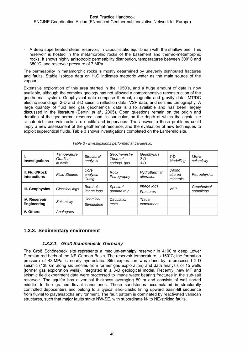
Best Practice Handbook ENGINE Coordination Action (ENhanced Geothermal Innovative Network for Europe)
40
- A deep superheated steam reservoir, in vapour-static equilibrium with the shallow one. This reservoir is hosted in the metamorphic rocks of the basement and thermo-metamorphic rocks. It shows highly anisotropic permeability distribution, temperatures between 300°C and 350°C, and reservoir pressure of 7 MPa.
The permeability in metamorphic rocks is mostly determined by unevenly distributed fractures and faults. Stable isotope data on H2O indicates meteoric water as the main source of the vapour.
Extensive exploration of this area started in the 1950’s, and a huge amount of data is now available, although the complex geology has not allowed a comprehensive reconstruction of the geothermal system. Geophysical data comprise thermal, magnetic and gravity data, MT/DC electric soundings, 2-D and 3-D seismic reflection data, VSP data, and seismic tomography. A large quantity of fluid and gas geochemical data is also available and has been largely discussed in the literature (Bertini et al., 2005). Open questions remain on the origin and duration of the geothermal resource, and, in particular, on the depth at which the crystalline silicate-rich reservoir rocks are ductile and impervious. The answer to these problems could imply a new assessment of the geothermal resource, and the evaluation of new techniques to exploit supercritical fluids. Table 3 shows investigations completed on the Larderello site.
Table 3 - Investigations performed at Larderello.
I. Investigations
Temperature Gradient in wells
Structural analysis
Geochemistry Thermal springs, gas
Geophysics 2-D 3-D
3-D Modelling
Micro seismicity
II. Fluid/Rock interactions Fluid Studies
Core analysis Cuttig
Rock Petrography
Hydrothermal alteration
Dating altered minerals
Petrophysics
III. Geophysics Classical logs Borehole image logs
Spectral gamma ray
Image logs Fractures
VSP Geochmical samplings
IV. Reservoir Engineering Seismicity
Chemical Stimulation
Circulation tests
Tracer experiment
V. Others Analogues
1.3.3. Sedimentary environment
1.3.3.1. Groß Schönebeck, Germany The Groß Schönebeck site represents a medium-enthalpy reservoir in 4100 m deep Lower Permian red beds of the NE German Basin. The reservoir temperature is 150°C; the formation pressure of 43 MPa is nearly hydrostatic. Site exploration was done by re-processed 2-D seismic (138 km along six profiles from former gas exploration) and data analysis of 15 wells (former gas exploration wells), integrated in a 3-D geological model. Recently, new MT and seismic field experiment data were processed to image water bearing fractures in the sub-salt reservoir. The aquifer has a vertical thickness averaging 80 m and consists of well sorted middle- to fine grained fluvial sandstones. These sandstones accumulated in structurally controlled depocenters and belong to a typical silici-clastic fining upward basin-fill sequence from fluvial to playa/sabcha environment. The fault pattern is dominated by reactivated variscan structures, such that major faults strike NW-SE, with subordinate N- to NE-striking faults.

Best Practice Handbook ENGINE Coordination Action (ENhanced Geothermal Innovative Network for Europe)
41
In the former gas exploration well GrSk 3/90, various stimulation flow tests and several well logging (temperature, pressure, resistivity, gamma ray, and sonic) were carried out to characterize hydraulic parameters of the reservoir rock. The in situ stress field was determined by integrating frac results and structural analysis. Detailed logging, including FMI (Fullbore Formation Imaging) and BHTV (Borehole Televiewer Tool), revealed petrophysical and structural characteristics of the Lower Permian section. This knowledge was used in drilling and stimulating the new well GrSk 4/05. Table 4 summarizes the investigations realised at Gross Schönebeck.
Table 4 - Investigations performed at Gross Schönebeck.
I. Investigations
Temperature Gradient in wells
Structural analysis Stress field
Geochemistry Thermal springs, gas
Geophysics 2-D MT
3-D modelling
II. Fluid/Rock interactions Fluid Studies Core analysis
Cutting Rock Petrography
Hydrothermal alteration Petrophysics
III. Geophysics Classical logs Borehole image logs
Spectral gamma ray
FMI logs Fractures
IV. Reservoir Engineering
Hydro. stim. Seismicity
Thermal Stimulation
Circulation tests
Tracer experiment
4D Reservoir Simulation
V. Others Analogues Geomechanics Borehole Stability
Corrosion effects on casing
1.3.3.2. Altheim, Austria
The Altheim power plant is located in Upper Austria, closed to the German border. It is based on the exploitation of the well-known aquifer of the Malm, at an approximate depth of 2000 m. In this region, several geothermal doublets exist and provide heating for spas or residences. The Malm aquifer in this region has excellent transmissivities estimated between 10-4 m2·s-1 and 10-
2 m2·s-1) and is permanently recharged by infiltration of hot fluids from the subjacent crystalline basement. This results in an apparent thermal gradient anomaly between the surface and the Malm aquifer, as values up to 50 K·km-1 can be measured in geothermal boreholes.
The main information available concerning the Malm aquifer geometry in this region comes from seismic profiles acquired between 1980 and 1990, when it was decided to actively use the energy provided by this warm aquifer in the region.
Borehole measurements were conducted in the first well, Altheim 1, between depths of 2100 m and 2300 m. An electric resistivity log was realized in order to isolate main fault zones (small values of electric resistivity). A gamma ray log, completed later in the same section of the well, confirmed results from this electric log. A sonic log allowed derivation porosity indicators in this section of the well. The "Sonic porosity" was estimated between 8 % and 28 %. Hydro chemical and isotopic investigations were also realised in the district of the Altheim doublet. These analyses showed that the main part of water in the Malm has meteoric origin, indicating a high

Best Practice Handbook ENGINE Coordination Action (ENhanced Geothermal Innovative Network for Europe)
42
regeneration component in this aquifer. Table 5Erreur ! Source du renvoi introuvable. shows investigations and results obtained in Altheim.
A very detailed numerical model was built in order to evaluate the potential of the aquifer and to model different solicitation scenarios (Goldbrunner et al., 2007). The study emphasized the importance of reinjection boreholes, since the Malm aquifer is strongly exploited by several geothermal utilization in the region.
Table 5 - Investigations lead and results obtained at Altheim.
I. Investigations
Ground Temperatures
Temperature Gradient in wells
Structural analysis
Geochemistry Thermal springs, gas
Geophysics 2-D
3-D modelling
II. Fluid/Rock interactions Fluid Studies Core analysis
Cutting Rock Petrography
Hydrothermal alteration Petrophysics
III. Geophysics Classical logs Spectral gamma ray
Sonic logs
IV. Reservoir Engineering
Hydro. stim. Seismicity
Chemical Stimulation
Circulation tests
4D Reservoir Simulation
V. Others Analogues
1.3.4. Critical overview of workflow processes
The workflow of geothermal exploration depends on 1) the geoenvironment, and 2) the previous knowledge of the site, i.e. whether it is a well-known geothermal field, or a new site.
All types of geological exploration start with the collection of available data. Except for volcanic environments, where obvious signs of geothermal activity are commonly observed, geothermal exploration is always carried out in places, where temperature information is available from boreholes. Additionally, the regional geology, type of rocks, age of rocks, tectonic history and present stress conditions of the area are important to estimate the characteristics of a potential reservoir.
Volcanic environment
The methods and the workflow applied are quite similar in Iceland and Bouillante. Structural geological mapping (in Bouillante supplemented by off shore seismic reflection data) was made to determine the main structural features. It was accompanied by geochemical and mineralogical analyses of the hydrothermal deposits. Sampling from hot springs and fumaroles (chemical and isotopic analyses) allowed determination of the fluid present and paleo-circulations (δD and δ18O analyses), as well as an estimate of the depth of the main geothermal reservoir and nature of reservoir rocks (δ7Li analysis).
In both sites, magnetotellurics is the most important geophysical method, as it maps the low resistivity zones typical for hydrothermal alterations. These alterations are related to present or past fluid flows. Magnetotellurics was supplemented by airborne surveys, magnetism gravity and EM to obtain data in remote areas difficult for access. The former is sensitive to

Best Practice Handbook ENGINE Coordination Action (ENhanced Geothermal Innovative Network for Europe)
43
hydrothermal alteration, the second gives information about deep changes in density, and the latter about shallow electrical resistivity anomalies. Additionally, in Iceland seismological methods as Vp/Vs ratio, and S-wave shadows are used to identify magma chambers.
Finally, in both sites the geological and geophysical data are integrated into a conceptual model of the geothermal field. The drilling location is determined from this model.
In Bouillante, Dipole-Dipole measurements as well as off-shore seismic imaging and airborne surveys could bring interesting information to the knowledge of the system. New chemical and isotopic analyses of fluids (waters and gases) collected from hydrothermal events could also be performed, and field sampling for mapping and characterising the hydrothermal mineral composition (clays, mixed layers), as well as their precise dating by innovative methods, would allow estimating the age of the most recent hydrothermal activity.
The small number of wells drilled in the Bouillante geothermal field, the absence of cores from existent wells, and the reduced measurements into the wells are a significant limitation for understanding this field. Moreover, there is no information about the stress field as well as the fracture orientation in the well. More wells and more logging would result in a greater amount of useful information about the field. This is less relevant in Iceland due to the many years of exploration.
Crystalline basement
Exploration in crystalline rocks is a challenging task since geological conditions are always complex and the subsurface heterogeneous. A common feature of geothermal reservoirs in crystalline rocks is that permeability is mainly controlled by fractures. Therefore, one of the main goals of the exploration in such areas is to clarify the geometry and kinematics of the main structural features. The first step is the analysis or production of structural maps and aerial photographs of the area. In areas covered by sediments, seismic reflection sections can provide critical subsurface information about major fault system(s) in the sediments and at the interface between the sedimentary cover and the basement.
In case of deeply buried crystalline basement, as in Soultz or Larderello, 2-D/3-D seismic exploration are very helpful for determining the structure of the major fault system(s) in the sediments and at the interface between the sedimentary cover and the basement. The critical point is to be able to detect the downward extent of the fault system inside the basement rocks, as seismic methods can still be refined in crystalline rocks. Innovative methods able to map fault structure at great depth in basement would be helpful. VSP (Vertical Seismic Profile) measurements recently performed in the Soultz and Larderello wells show encouraging results in terms of permeable fault zone detection, both in and near the wells.
However, there is a need to better characterize the inter-well domain. Even in Larderello, where hundreds of wells have been drilled, the circulation paths are far from being defined due to the complex geology of the area. A better understanding of geological, hydrogeological, and geophysical features between wells by detailed wellbore geophysics and correlation analyses between wells is desirable. In Soultz, the only method currently used is micro-seismicity related to hydraulic stimulations, but the relations between induced seismic events, permeability, in situ stress, and the fracture system are debatable (Shapiro et al., 1999). Innovative concepts related to electric or electromagnetic signals would be helpful.
Inside the well the mineralogical composition of the fracture filling (calcite, silica, clays, sulfides, etc…) needs a better characterization, which is actually not provided by logs. High-resolution

Best Practice Handbook ENGINE Coordination Action (ENhanced Geothermal Innovative Network for Europe)
44
geochemical tools able to detect the chemical or mineralogical composition of fractures would be very helpful for designing chemical stimulations.
Sedimentary environment
The main advantage of sedimentary environment is that standard geophysical techniques applied in hydrocarbon exploration can be used. Borehole data and the results of usually 2-D, and sometimes 3-D seismic surveys are available. The lithology and (hopefully) the temperature are known from the boreholes, and, when a reservoir is identified, it can be followed in the seismic sections, and its volume can be estimated. In this particular geo-environment, where permeability is controlled by porosity, relation between porosity and permeability are known. As porosity is determined more easily from seismics or geo-electrical methods, this offers an attractive option to estimate permeability in the reservoir.
A main problem of the sedimentary environment is that the porosity and therefore the permeability decreases with depth due to compaction and diagenesis of sediments, and at depth where the temperature reaches a suitable value for electricity production (~4 km – 6 km), the permeability of sediments may be too low to provide enough water circulation. Therefore, acidization and other chemical techniques often provide good results for permeability enhancement and could be further developed.
Groß Schönebeck is an example of a well-documented EGS in a sedimentary environment. The project started immediately on a reservoir scale, as the well Groß Schönebeck 3/90 already existed from earlier hydrocarbon exploration. The well penetrated the Rotliegend sandstone reservoir, which is a widespread formation in the North-Eastern German Basin. The formation is well known from other wells and seismic sections. Permeability measurements have been carried out on core samples from other wells. Reservoir engineering is currently on going. The success of the project depends on how the reservoir permeability can be improved without shortcutting the two wells.
1.4. FROM THE STATE OF THE ART TOWARD THE FUTURE
The search for geothermal and tools of investigation have changed. In the ’80s the main search focused on large reserve, high enthalpy systems with T >> 150°C and EGS concept was at its early stage. Now, lower temperature can be exploited and EGS technology is becoming more mature. What was considered unexploitable or not economic in the past is becoming possible nowadays, if bottleneck for exploitation are overcome. Moreover, advances in technology make what is uneconomic today economic tomorrow.
In the framework of the ENGINE Coordination Action a main issue has been the definition of innovative concepts for the development of UGR or EGS. Important technical obstacles to attaining near-term and long-term EGS and UGR goals and objectives exist in the areas of resource characterization; reservoir design and development; and reservoir operation and management. In all these fields investigation and exploration provide a fundamental base. Resource characterization regards research in geothermal gradients and heat flow; geological structure, including lithology and hydrogeology; tectonics; induced seismicity potentials. Reservoir design and development includes research in fracture mapping and in-situ stress determination; prediction of optimal stimulation zones. Reservoir operation and maintenance includes research in reservoir performance monitoring through the analysis of temporal variation of reservoir properties. Moreover, in a new era of geothermal development, the sustainability

Best Practice Handbook ENGINE Coordination Action (ENhanced Geothermal Innovative Network for Europe)
45
and mitigation of environmental effects should be defined and optimised prior to major financial commitment.
1.4.1. Goals of exploration
During the past, 50 years of exploration large amount of temperature data and significant knowledge of subsurface geology were accumulated. Based on this a priori knowledge several areas prospective for EGS exploration can be outlined in Europe and many regions in the World. Further exploration must prove the two most important conditions for developing an EGS: temperature higher than 85°C, and existence of permeable rocks either due to porosity in sediments or due to fractures in crystalline and volcanic rocks.
Two main goals should be addressed by exploration and investigation: to reduce the mining risk by cutting the exploration cost and increasing the probability of success in identification of EGS in prospective areas, and to provide all necessary subsurface information to guarantee the best exploitation efficiency, the sustainability of the resource and the lowest possible environmental impact.
Technological challenges targeted to these goals are mainly aimed to: 1) find improved and newly developed methodologies able to map reservoir condition suitable for EGS exploitation, in particular at local scale; 2) provide data integration (static and dynamic) and uncertainty analysis. Integration of technology and multidisciplinary evaluation of data, such as the one speeding up in the last 15 years for hydrocarbon exploration, must become a core competency also in the geothermal world; 3) find tools able to improve imaging between existing wells and performing real time measurements: some of these tools might be borrowed from oil and gas exploration but adapted to meet unique geothermal conditions, such as high temperature and pressure and possibly aggressive chemical composition.
1.4.1.1. Characterization of host rock conditions What starting conditions are necessary to develop/stimulate an EGS? What are the conditions classifying a thermally suited area for the development of an EGS? There is a need to refer to existing geothermal sites, for which data on heat distribution and permeability networks are available to model pathways for fluid circulation, gas-water-rock interaction processes (and their effects on effective porosity and permeability) and heat exchange. Such equivalent conceptual models should account for local geological structure and integrate the most significant datasets and their interpretation on reference key areas, like Larderello, Bouillante, Soultz, Groß Schönebeck. These models must be updated as soon as new data or new experiences and results are available. Technological platforms could be promoted to develop new methods and tools, test hypotheses in situ and accuracy of conceptual models. A significant improvement of the knowledge is expected from natural analogue on which hypotheses could be tested about for example circulation of fluids in relation with seismicity and heterogeneity of the lithologies, thermal imprint of fluid circulation. The links with other investigation programmes like nuclear waste storage, capture and geological storage of CO2 and oil and gas field development will be developed to take benefit of existing installation and experiences.
Advances in exploration data acquisition, processing and workflows need continuous attention in order to provide better images in complex areas. Three main parameters should be known before drilling for exploitation of potential geothermal reservoirs: permeability, temperature and stress field (priority ranking). Temperature defines the energy stored in the subsurface. Permeability characterizes the flow rate that could be produced and reinjected in the system, which is directly linked with both temperature and the amount of energy that can be expected

Best Practice Handbook ENGINE Coordination Action (ENhanced Geothermal Innovative Network for Europe)
46
from a doublet system. Information on stress conditions allows selecting the most favourable sites for high flow rates, for drilling and for enhancement of the natural permeability of the system.
Presently, at a regional scale different exploration methods are available for estimating temperature, geology and stress distribution at depth, but it is very hard to map permeability. At local scale, where details of the reservoir and its potential energy need to be assessed, resolution is still rather low, while main gaps exist in combining geological, geochemical and geophysical data coming from different methods. Experiences made in hydrocarbon exploration must be modified for EGS, since EGS requires usually more knowledge about fracture and fault systems with respect to their role as potential water conduits. The reservoir imaging strategy should include large scale approaches supplemented by high-resolution experiments. Further benefit should come from adapted processing techniques.
Besides the structural inventory of the subsurface, the mapping of permeability, temperature and stress field is the key elements with priority research needs. The percentage of an innovative impact is estimated as follows:
- Priority A Mapping of permeability (50%)
- Priority B Mapping of temperature (40%)
- Priority C Mapping of stress field (40%)
a) Mapping of permeability
Even if the permeability is locally well known from borehole measurements, it is far from evident that the permeability obtained at one given point could be extrapolated (combining surface geophysics and borehole data) to a nearby location. This can result from variations in the facies of the host rocks, to changes in the fracture network, or in the fracture properties that often control the permeability at great depths.
Workflows encompassing fault interpretation from 3-D geophysics and geostatistic tools, 3-D retro-deformation and fracture interpretation from well data should be further developed to give a base for possible pathway interpretation and reconstruct the evolution with time. Palaeostress maps may also help in distinguishing between open or closed pathways.
Acoustic (compressional and shear wave) signatures of deforming rocks should be investigated with the aim to provide a database on rock physics and rock deformational properties so that high resolution 3-D or 4-D seismic surveys can be used to image reservoir enhanced permeability zones or to identify rock units where enhanced permeability could potentially occur. Moreover, the development of an integrated tool to handle fault and fracture analyses, drilling engineering, logging, and seismic data would provide great benefit toward a detailed permeability assessment. The link between microseismicity and flow paths should also be further investigated.
b) Mapping of temperature
The mapping of temperature is essentially achieved by interpolating available temperature logs over a given area. It is now possible to compute the large scale temperature distribution by a numerical 3-D model and to adjust the geothermal parameters from local temperature measurements. Indeed, the existence of unknown local advection or convection processes due to water circulation in the host rock represents challenges for temperature prediction at these depths. Numerical models can reproduce these effects (Clauser, 2003; Kohl et al., 2000) but require adequate field data. A broad range of thermodynamic processes and hydrodynamic

Best Practice Handbook ENGINE Coordination Action (ENhanced Geothermal Innovative Network for Europe)
47
regimes (fracture networks, multiphase flows…) should be incorporated in the main reservoir simulators in order to model at best geothermal systems and their evolution with time.
However, the extension of large-wavelength heat flow anomalies at depth is often inaccurate due to the improper knowledge of the causes of the heat-flow anomaly. The existence of convective and advective cells, such as met in Soultz and in the Rhine Graben area, hinders a temperature extrapolation to greater depth and can lead to wrong evaluation of thermal gradients.
These convective and advective processes should be identified and characterized through detailed geochemical studies comprising definition of water chemistry, application of suitable geothermometric techniques (hydrochemical and gas geothermometers), mapping of CO2 fluxes from soils, defining electrical resistivity variations, etc. Neural network analysis could be also useful in order to extrapolate laterally and at depth data coming from temperature logs and geothermometric data (geochemical and geophysical data)
It would be of great interest to build digital databases comprising all information available in Europe that is relevant for geothermal resource exploitation (temperature, geology, logging test results...). These databases would then allow computing temperature maps at regional scales plotted on some relevant geological interfaces. For example in Western Europe, temperature distribution at the top of Trias, at the interface between sedimentary formations and basement rocks, in the uppermost 500 m of the basement, and in Eastern Europe, at the top of the Tertiary are of strong interest. Because numerical models used to compute the temperature distribution are based on the geological knowledge, there is a need to produce litho-tectonic maps at the interface between sedimentary formations and basement rocks.
There is the need to calibrate stratigraphy, reservoir, fluid circulation and thermal history in under-explored areas. Measures to be taken need to involve a critical screening of thermal data, developing baseline temperature models, and investigating the modification through the time of reservoir exploitation, providing the essential thermal rock properties, and combining the temperature field properties with reservoir properties. Analogue sites should be studied and results incorporated in the workflow in order to help the interpreters to take advantages from known similar conditions. Other investigation programmes like nuclear waste storage, capture and geological storage of CO2 and oil and gas field development may also provide useful information and experiences.
c) Mapping of stress
Evidences exist and show the influence of the stress field on hydro fracturing. The knowledge of spatial stress distribution (map and depth) on a local as well as on a regional scale is thus fundamental for any future experiment. Mechanisms of rupture and propagation of an existing fault system and related displacement remain debated, especially in connection with the circulation of fluids and efficiency for improving sustainable permeability.
The circulation and accumulation of fluids in the crust are fundamentally controlled by the geometry of the fault and fracture systems. The ability of these systems for the channelling of fluids is directly dependant of the stress field (orientation and intensity). Favourable and unfavourable conditions exist depending of the tectonic context and geological environment.
The mapping of stress can be obtained at various scales. At a continental scale, tectonic models provide a good estimate of the zones of different regimes. At a local scale, when exploration boreholes are available, the determination of the stress field can be done through microseismic interpretation or through hydrofracturing.

Best Practice Handbook ENGINE Coordination Action (ENhanced Geothermal Innovative Network for Europe)
48
The major knowledge gap concerning stress estimation is located between regional and local scale. An important problem is that local stress variation can occur due to the existence of faults or magma bodies. Indeed, a possible objective for research could be to estimate stress at different depths, using a modelling procedure and taking in account pre-existing faults and any evidence for magma. The relationship between stress field and permeability should also be researched further.
Definition of in-situ stress, which is crucial both for understanding the dynamic of the fluid circulation and to help during exploitation, foreseeing the drilling requirements to avoid collapses, stacking and guarantee wellbore stability, as well as controlling stimulation effects including induced seismicity.
1.4.1.2. Integrate data Data integration (e.g., static and dynamic) is a reoccurring theme throughout most Exploration and Reservoir Characterization elements and must be considered a key area to improve tools. There is no single software tool capable of providing a fully integrated reservoir model all the way from geophysics and geochemistry, through geological model to flow model.
Several physical parameters (density, wave velocity, electrical resistivity, thermal conductivity…), as well as chemical and mineralogical properties are coupled with temperature and can be imaged by different geological, geophysical and geochemical methods. Thus, the definition of possible targets for EGS could be improved by the use of a 3-D modelling platform, in which all solutions from geological, geochemical and geophysical modelling, direct and inverse, could be combined and analysed.
Geophysical methods are suitable to determine the architecture, geometry, and quality of target intervals. However improvement of existing methods and in particular reasonable combination of different, most sensitive techniques (passive and active seismic, MT, and others) are needed to meet the requirements of modern geophysical exploration. The interpretation of geophysical features must be supported and validated by petrophysical laboratory and borehole measurements, as well as modelling. Petrophysical studies should be extended in order to define the main relations between physical parameters, mineralogical composition, fluid chemistry and water-rock interaction effects. This would improve the knowledge of the whole resource and would allow optimising exploitation strategy. E.g., hydro-fracturing is not the only option to enhance the permeability of reservoir rocks: selective dissolution should also be taken into account (as a technique to increase effective porosity and permeability) as it could be more effective than fracturing, provided that it is applied to suitable lithological frameworks (e.g., sandstones made up of quartz and silicate minerals but also containing relevant amounts of fast-dissolving carbonate minerals) and under carefully selected conditions.
Lithology and Fluid Prediction can be improved using full wave fields. Reflection seismic through a detailed seismic attribute analysis, gravity, electromagnetic data allow defining density contrasts, porosity and permeability, nature of fluid. All these information, monitored in time, are used to make inferences about reservoir dynamic and helps in optimization of drainage. Depth migrated seismic should pay special attention on the velocity model construction. New inversion modelling tools should be defined, joining different geophysical information.
Eventually, geothermal community standards for additional data types should be developed to improve the maintenance of high quality databases and data handling and to facilitate the input of these data into simulators.

Best Practice Handbook ENGINE Coordination Action (ENhanced Geothermal Innovative Network for Europe)
49
1.4.1.3. Improve imaging between wells The necessity to guarantee the sustainability of the resource and zero environmental impact add focus on high availability of water including produced water injection solutions, no or reduced fluid discharge, no or reduced induced seismicity. Mapping of environmental condition before entering new areas and monitoring during operational phases is needed. This includes methods to assess impacts from discharges to shallow waters and emissions to air, the effects of compliance to a zero discharge versus a zero harmful discharge framework. A baseline should be established mapping the conditions before operation, predicting the effects of activity (risk and impact based evaluations) and monitoring actual condition during stimulation and production. To this aim a main technological challenge is the development of improved logging tools for imaging physical conditions at depth but also capable to resist at very aggressive condition (high temperature, high pressure, highly corrosive fluids) maintaining the costs as low as possible and guaranteeing a quick and reliable data transfer and storage.
As the EGS technology aims at exploiting heat in the ground at every point of the crust, the needs for mapping of permeability are more relevant at the scale of the reservoir to locate at best further boreholes. Today, various logging techniques give access to the fracture orientations and density crossing the borehole. The major issue is that the properties of the media between boreholes are poorly constrained.
In order to avoid these gaps, several geophysical tools need to be developed with the following objectives: 1) to identify the extension of a given fracture zone which intersects the borehole, and 2) to identify and characterize important fracture zones, which do not intersect the borehole. In other words, there is a need to develop a geophysical tool to image the 3-D structure within the inter-well domain in hard rocks. Possible improvements to achieve this goal are listed below :
- Logging through casing should be improved. Cased-hole logging technology is a research field in oil and gas but the different casing problems of geothermal wells requires ad hoc solutions to be defined.
- A main effort should be made to design and demonstrate high temperature (> 200°C) measurement-while-drilling (MWD) tools using a unique high temperature battery system. Research projects made in the hydrocarbon exploration are focused on devices incorporating silicon-on-insulator (SOI) fabrication technology into the manufacturing process for the microchips required. The goal is to improve the reliability of high-temperature electronic components found in MWD tools needed to improve drilling efficiency and success rate at depths up to 8 km and temperatures greater than 200°C.
- The development of a combined microseismic receiver-tiltmeter system would provide an advanced hydraulic fracture mapping tool to measure created fracture geometry. Such system would reduce the need for observation wells and reduce overall costs.
- The use of borehole seismic imaging supplemented with electromagnetic methods would help to map fluid content at distance of hundreds of meters from the bore hole with resolution comparable to existing logging methods. Since seismic methods provide information on the structural and mechanical properties of the medium and the conductivity provides independent information on the fluid state, these jointed measurements will provide a more complete map of the fluid distribution and matrix properties.
- Computational improvements should be made in order to obtain 3-D electrical tomographs, providing the equivalent of electric logs deployed every few meters between existing wells. These high-resolution tomographs have been used with success for oil and gas formation characterization and monitoring subsurface fluid movement (i.e. tank leaks, steam floods), but should be adapted to geothermal condition where also temperature changes must be

Best Practice Handbook ENGINE Coordination Action (ENhanced Geothermal Innovative Network for Europe)
50
taken into account. The Electrical Resistivity Tomographs (ERT) would also address the problem of tracking the fluid during stimulation or production.
1.4.2. Concluding remarks The demand for better understanding of the reservoir is setting new challenges, which are technical as well as organisational. A reservoir study project requires the availability of all the relevant prospect information, which on turn should be available to all the applications involved in the management and analysis of such a project. The improvement of the conceptual model to decrease the drilling risk of the exploitation wells needs more integration between different methods, advanced 3-D modelling coupled with thermo-hydrodynamic modelling and rock physics measurements.
Integrated workflow includes geophysical imaging, interpretation and earth modelling, and provides all information necessary for reservoir characterization and well design and simulation. An effective planning should incorporate all data at different scales, making the link between geology and other disciplines. The next generation of exploration tools should include an increased geological realism and representation of uncertainties, improved physics and chemistry, and should be designed for new and future computing environments.
The technical challenge is to create the systems and technologies that will streamline and optimise this sophisticated and complex workflow. The logistical and organisational challenge is to create the units and the processes within the geothermal community.
The new tools would permit the asset teams to work differently, taking advantage of a higher level of professional interaction among the various geosciences and engineering disciplines.
With the advances in geosciences knowledge we can integrate the exploration workflow, advanced volume based visualisation technology and the well design parameters, to optimise the drilling engineering process using the available information from field measurement. Establishing predicted fluid circulation and temperature distribution for optimised well design, interactively locating the optimal well path and using real-time monitoring while drilling would allow achieving modelling-while-drilling, as well as the interactive redesign and re-engineering of the well path. All of this would save both significant time and expense in the very costly drilling process, and would allow the minimum impact to the environment while providing the sustainability of the accessed resource.

Best Practice Handbook ENGINE Coordination Action (ENhanced innovative Network for Europe
51
2. Drilling, reservoir assesment and Monitoring
2.1. DRILLING
Drilling operations are performed in order to open up geothermal reservoirs for energy exploitation. During the drilling process, the drilling rig has to fulfil various functions. It has to rotate the drilling bit – either by rotating the whole drillstring or by delivering the hydaulic energy to drive the downhole motor - in order to achieve penetration into the drilled formations. It has to ensure circulation of the drilling mud, so as for the drill cuttings to be transported up the well bore, it has to provide traction power, for the drill string to be pulled out of the well, and to control the weight on the drill bit during drilling.
The choice of an appropriate drilling rig is one of the most important decisions in well planning. The rig should have a sufficient safety margin and fit in its technical specifications (hook load, rig horse power, etc.) to the specific well planning. In order to avoid unnecessary costs, standard bit sizes and casing diameters should be used wherever possible.
At the same time particular necessary differences in well design between hydrocarbon wells and geothermal wells have to be taken into account. Due to the high production rate in geothermal wells for example, well diameters, and correspondingly diameters of injection and production strings have to be bigger in geothermal wells.
A rig management system which has been developed by many drilling companies is a key to attain a cost effective well. This directs the drilling personnel of different positions to be familiar with their respective task in the day to day drilling operation. Familiarity with safety, well control, drill string design, cementing calculations, mud formulation and experience in dealing with numerous drilling problems, coupled with dedication by rig personnel will for sure result in a cost effective drilling operation.
With only very few exceptions a drilling mud will circulate within the well bore during the drilling operations. The drilling mud has to fulfil various main functions within the drilling process. First of all, it serves in transporting cutting material away from the drill bit, up the well bore. Secondly it helps to stabilize the well bore by means of balancing the pressures at the borehole wall, and thirdly it might be used for cooling the drilling equipment. In order to enable a continuous operation, a sufficient supply of drilling mud has to be ensured. Mud pumps have to be dimensioned such that they are capable of providing drilling mud in adequate quantity per time unit. Mud cleaning facilities have to be installed and, if necessary, mud cooling services as well.
The drilling personnel should be properly trained and familiar with all aspects in the drilling operation. Training of rig personnel should be a continuous process as this will enhance their capabilities in producing an economical well.
2.1.1. Drilling sediments - Gross Schönebeck After Sperber et al. 2005, the drilling techniques applied in exploiting geothermal reservoirs do not fundamentally differ from those applied in drilling hydrocarbon (oil or gas) wells. They are to be found in standard textbooks like Bourgoyne (1986), Nguyen (1996), Jackson (2000) or Nguyen et al. (2006). The main fields to which particular attention has to be paid when drilling geothermal wells in sedimentary environments are borehole diameter, directional drilling and techniques targeted at avoiding formation damage.

Best Practice Handbook ENGINE Coordination Action (ENhanced Geothermal Innovative Network for Europe)
52
In order to obtain flow rates in geothermal wells, which are high enough to secure an economically viable operation of a geothermal power plant, the borehole and casing diameters have to be big enough. Thus diameters of geothermal wells are generally bigger than the diameters of corresponding hydrocarbon wells of comparable depth. This has implications not only for drilling costs, but also for issues of borehole stability, since a given formation with certain parameters of strength, and a certain, generally anisotropic, stress field, the formation is more prone to borehole breakouts, the bigger the borehole diameter is. This becomes even more important if the well is deviated. It is therefore recommended to carefully investigate the in situ stress field and borehole stability ahead of well planning, such that well path (particularly its direction in relation to the stress field), mud weight and casing program can be chosen accordingly.
In order to hit the subsurface target zone with a sufficient degree of accuracy, it is generally necessary to drill directionally. This is accomplished through the use of proper bottom hole assembly (BHA) configurations, instruments to measure the path of the well bore in three dimensional space, data links to communicate measurements taken downhole to the surface, mud motors and special BHA components and drill bits. Drilling parameters like weight on bit (WOB) and rotary speed (rmp) are also sometimes used to deflect the bit away from the axis of the existing well bore. The most common way to point the bit in the direction one wants to drill is through the use of a bent in a downhole steerable mud motor assembly. The bent points the bit in a direction different from the axis of the well bore, when the entire drill string is not rotating. By pumping mud through the mud motor, the bit turns, while the drill string does not rotate, allowing the bit to drill in the direction it points.
The drilling bit generally has to be chosen according to the geological formation to be drilled. In sedimentary environments this will in most cases be a roler-cone bit, which either has steel teeth or may have hard metal inserts made from tungsten carbide (TCI-bits). Polycrystalline Diamond Compacts (PDC) bits have been used successfully when drilling uniform sections of carbonates and evaporates, that are not broken up with shale stringers (Bourgoyne et al., 1986) Although successful use of these bits has also been reported from sandstone, siltstone and shale formations, PDC bits can certainly not be recommended generally in these formations.
Although a high drilling speed (ROP = rate of penetration) is generally desirable in order to keep drilling costs low, for technical reasons it is not always recommended. While drilling ductile formations like clay or claystone for example, it may be recommended to reduce drilling speed, and, if necessary, also the WOB in order to keep the bit in a cutting mode, and not turn into a pressing mode.
Differential sticking occurs, when the drill string is held against the well bore by a force. This force is created by the imbalance of the hydrostatic pressure in the well bore and the pore pressure in the permeable formation (Bowes, 1997). When the hydrostatic pressure is greater than the pore pressure, the difference is called the overbalance. The resultant force of the overbalance acting on an area of drill string is the force that sticks the string. Differential sticking might occur with a stationary or slow moving string, when an overbalance is present, across a permeable formation, in a thick filter cake, when a contact exists between the string and the well bore; it is proportional to the contact area between drillstring and filtercake-covered borehole wall section. This means deviated sections of wells in permeable, sedimentary environments are particularly prone to differential sticking. Any action to reduce the aforementioned causes (e.g. lowest possible density and solids content of the drill mud) will reduce the risk of differential sticking.
Drilling salt formations is a particular challenge in its own, where highly plastic salt formations can easily cause casing collapse. This is a particular risk when salts are found deep in the well,

Best Practice Handbook ENGINE Coordination Action (ENhanced Geothermal Innovative Network for Europe)
53
since the plasticity of salt increase with temperature. Careful attention has to be paid to the selection of drilling speed, adjustment of mud weight, and choice of an appropriate (thick-walled) casing.
In order to achieve the highest flow rates possible from the geothermal well, formation damage due to, for example, mud invasion has to be avoided. When drilling in sandstone dominated formations it is desirable to avoid mobilisation of clay minerals. For this purpose it is recommended to drill under balanced or near balanced. Special drilling mud should be used which reduce clay mineral mobilization. A marble-flour might be added to the drilling mud which will help building up a thin mud cake, which protects the reservoir formation. If necessary this thin mud cake might later easily be removed through acidization.
Thermally induced stress on the casing during hot water production has to be considered and casing damage generally has to be prevented. This commonly requires a complete cementing along the whole profile. Alternatively the uncemented part of a casing string has to be pulled in tension in order to compensate the thermally induced elongation.
In order to prevent fluid circulation behind the casing within the overburden, cementation up to the surface is essential. The bond between tubing, cement and the rock has to withstand the thermal tensions and the pressure changes during the entire life span of the well. Blast furnace cement has turned out to be very suitably. The process of cementation up to the surface represents a high pressure load for the unlocked formations. The cement slurry density can be adapted to these conditions by specific additives. In Groß Schönebeck cement slurry densities of 1300 kg/m³ were reached with sufficient firmness.
Usually cementing of a well will be performed from the bottom to the top, but in case this is not successful, a squeeze cementation can be performed from top of the well to, for example, the former cement infiltration zone. It is generally recommended to verify the successful placement of the cement. This can either be achieved by means of conventional cased hole logging operations or by thermal logging.
Attention has to be paid in case gas bearing formations have to be drilled. The mud weight has to be chosen high enough, as to avoid the gas to enter the drilling mud. Potentially gas bearing formations also have to be considered when planning the casing program for the well.
2.1.2. Drilling volcanics - Iceland In this paragraph drilling technology applied to shallow (<3500 m) high-temperature drilling (defined as >180°C at 1000 m and not exceeding 320°C) in volcanic systems will be described. Volcanic systems are in one way or another associated with volcanic activity. The heat sources for such systems are hot intrusions or magma. They are most often situated inside, or close to, volcanic complexes such as calderas and/or spreading centers. Permeable fractures and fault zones mostly control the flow of water in volcanic systems.
The majority of all high-temperature geothermal wells in Iceland are drilled to 1500–3000 m. Many of them are drilled as directional wells like mostl of the geothermal wells in sediments -. The trajectory chosen is rather similar, a kick off point (KOP) at 300–600 m after landing the anchor casing and then a build-up to 30–45° after which the inclination is maintained to total depth. The resulting horizontal displacement is commonly 700-800 m. Directional wells are preferred for environmental reasons, and the targeting of near-vertical structures is easier.

Best Practice Handbook ENGINE Coordination Action (ENhanced Geothermal Innovative Network for Europe)
54
The drilling rigs used for geothermal drilling are oil well rigs with 200 - 450 t hook load capacity and were equipped with rotary table drives, but now many of the rigs have a top-drive. To be able to maintain cooling while tripping into a well is very important as the bits and tools used are destroyed or have a shorter life is they are exposed to high temperatures.
In order to optimize drilling performance and thus reduce drilling costs, it is recommended to look at a curve potting depth vs. days that the drilling-job has taken. Any “flat spots” where there is no advance in depth for several days will clearly show, which will indicate that there may be potential for operational improvement.
Mud motors are required for directional drilling, but they were also found to improve the rate of penetration a lot, contrary to the experiences of drilling granites in Soultz. In Iceland, mud motors have therefore also been used in drilling vertical holes.
Figure 7 - Downhole motor (Moineau - Motor) for directional drilling (A. Sperber).
Mud motors have parts of elastomers (rubber to form the sealing shape of the stator) that cannot take high temperatures. This problem is addressed by cooling the well through the circulation of drilling mud. This works so efficiently, that a temperature of less than 100°C can be maintained in a 2000 m deep well even though the reservoir temperature is over 300°C. Effective cooling of the well also allows Measurement While Drilling (MWD) tools to be run deep in the hole just above the mud motor.
The BHA is the lowest part of the drill string. In the past there was a drill bit and on top of it the drill collars to exert load /WOB) to the bit and then stabilizers to keep the string in the middle of the hole and prevent bending (buckling). Now the BHA usually contains a shock absorber, the mud motor, the Measurement While Drilling (MWD) tool, and then the drill collars with a hydraulic jar to free the string should it get stuck. On top of the drill collars there is a key-seat reamer and to smooth the transition over to the normal drill pipes a few “heavy-wate” drill pipes.

Best Practice Handbook ENGINE Coordination Action (ENhanced Geothermal Innovative Network for Europe)
55
The life of drill bits has steadily improved especially the ones with journal bearings and with hard metal inserts as “teeth” and to maintain diameter (“gauge protection”). These are considerably more expensive but can be rotated over 1 million revolutions and drill some 100m perhaps up to 1000 m without being replaced. Polycrystalline diamond bits (PDC) have found some use in geothermal drilling. They can drill fast even without a mud motor, but the rotary torque is usually twice as high and life shorter than for a good tri-cone bit.
Geothermal wells are designed to enable safe drilling into geothermal reservoirs and then to allow production of steam and water over several decades. In volcanic systems, geothermal fluids are compatible as far as the scaling chemistry is concerned, so that the produced fluid can come from any depth, as long as the temperature and flow volume requirements are met.
This means that the open hole part of geothermal wells is usually over 1000 m long and is supported by a slotted liner. This allows any fluid to enter the well. Most geothermal wells have 3–5 cemented casing strings, the deepest one to 700–1500 m (production casing). The expected productivity of the reservoir and target output of the well primarily influence the diameter selection.
For most HT geothermal wells the selection stands between a 9-5/8” production casing and a 13-3/8” casing. In case the well productivity is high enough, large wells with a 16” production casing are drilled as well. If the permeability of the reservoir is excellent then the diameter of the wells becomes the limiting factor as far as output is concerned. The output is roughly proportional to the cross-sectional area of the production casing. The most common casing strings used are: 7” or 9-5/8” (for slotted liner), 9-5/8” or 13-3/8” for production casing and then 18-5/8” or 20”, 22-1/2” or 24” 1/2etc. The reason for the many casing strings is to support the hole and especially to provide safety in controlling blow-out´s. The last cemented casing string, the production casing, also has to consider the minimum target temperature by reaching at least that deep into the reservoir. As a very rough “rule of thumb” for each section of the well being drilled, the casing needs to cover 1/3 of the target depth for that section. For example in a 2400 m hole with three cased sections the production casing should reach 900 m, the anchor casing to 300 m and the surface casing to 100 m. Note that by targeting the well to go deeper, all casing strings need to be longer.
The detailed and final casing program is planned once the expected temperature and pressure profile is known for a particular drilling location. This has to include considerations on the depths at which the target temperature is reached, and the general geological conditions.
For very permeable wells and where the boiling point is within the cemented casing, wells have successfully operated without a slotted liner, so called “barefoot” completion. This is also the completion of choice, when drilling into shallow steam caps, where “kicks” (sudden eruptions) are most common in the 100–300 m interval where there is boiling ground. For such wells, it is difficult to run the slotted liner, which may in cases not be possible at all due to “kicks”.
The casing steel grade takes notice of the H2S found in the geothermal fluid and usually grade API K-55 or L 80 is used.
Casing connections are mainly screwed API buttress thread but other connection types are now also found. In Iceland the 18-5/8“casing and 22-1/2” are butt-welded to allow slim clearances in the 21” and 24” drilled holes. All low temperature wells in Iceland use butt-welded connections and the casing is API line pipe.

Best Practice Handbook ENGINE Coordination Action (ENhanced Geothermal Innovative Network for Europe)
56
18-5/8" Anchor casing (473,1 mm x 12,32 mm),96,5 lb/ft (143,61 kg/m), X-56, butt weld, R3.
Casing head 20-3/4". Slip-on weld
800 m
350 m
Float-collar with stab-in 13-3/8"
Float-shoe 13-3/8"
Flot-collar with stab-in 18-5/8"
Float-shoe 18-5/8"
Centralizers every third joint
13-3/8" Production casing (339,7 mm x 12,19 mm),68 lb/ft (98,46 kg/m), K-55, buttress, R3
Master Valve12" x 900 ANSI
21" Bit
17-1/2" Bit
12 1/4" Bit
Expansion spool 18-5/8" x 13-3/8" CSG
Kill line ANSI 3" x 900 RTJ
Valve on annulus ANSI 3" x 900 RTJ
Centralizer
2200 m
Drilled ø20 mm, 8 holes
103 mm
80 mm
Liner hanger for 9-5/8"
9 5/8" Slotted liner (244,5 mm x 12 mm),47 lb/ft (69,94 kg/m), K55, buttress, R3
Casing shoe
22-1/2" Surface casing (572 mm x 12,7 mm),srw, butt weld, X-5226" Bit
90 m
Seal
Centralizers every third joint
Figure 8 - A typical large-diameter HT-well in Iceland (S. Thorhallsson).
By standardizing on two to three casing program sizes the inventory of drilling tools becomes simpler and the drilling become routine. This in time contributes to lowering costs. The casing program is virtually the same for directional wells as for vertical ones.
In Iceland water based bentonite mud is used while drilling with large bits >17-1/2“, to obtain adequate hole cleaning. The low-solids water based mud (SG 1.02) is a “simple” one made with high yield bentonite clay (Wyoming bentonite), and the additives are only caustic to maintain high pH, and a dispersant. In order to control artesian overpressure in wells, a high density mud of SG 1.4 is occasionally prepared by adding grinded solids like barite etc.

Best Practice Handbook ENGINE Coordination Action (ENhanced Geothermal Innovative Network for Europe)
57
In the productive part of the well where very often severe mud losses occur, water-only is the preferred drilling fluid, perhaps occasionally using polymer or mud-pills to clean fill-ins. It is felt that less formation damage is caused by the use of water and also it is of course less expensive than mud and allows uninterrupted drilling after the desired loss zones are encountered.
Lately methods that attempt to overcome the formation damage have been applied by what is called “balanced drilling” (aerated drilling) or sometimes “underbalanced drilling” (Hole, 2006). It requires large air compressors, a rotating head, and a separator on the flow-line. Similar amounts of water are pumped into the hole as in normal drilling, together with the air. Compressed air and soap is mixed with the drilling fluid (usually water only) thereby reducing the density so much, that the pressure inside the well will be no greater than the respective reservoir pressure. Thus no fluid or cuttings should be lost to the formation.
When wells are drilled into steam dominated reservoirs, using compressed air alone is the preferred method. After intersecting steam it flows out of the well together with the air. Remarkably the rate of penetration for normal rotary drilling goes up as well, offsetting in part the increased cost. On average, these wells are reported to have up to twice the output of conventionally drilled wells in the same field (Hole, 2006).
Cementing is one of the most critical and time consuming operations of the drilling effort. Zones of unwanted circulation losses were treated in the past by stopping soon thereafter and cementing to heal the loss, taking 1-3 days, but now it is common practice to bypass these zones. Good cementing can nevertheless be obtained by inner-string cementing up to the loss zone. Inner string-cementing allows cementing large diameter strings through drillpipe or tubing that is inserted and sealed in floating equipment, a method which is sometimes less costly than cementing large casing using the conventional plug displacement method. Flow of water top down in the annulus then keeps the loss zone open and thereafter the annulus is filled up by “squeeze cementing” pumping down to the loss zone. Recently “reverse” cementing where the cement is pumped down the annulus, has been successfully tried. In some countries “foam” cement is used to reduce the slurry density and loss of circulation material is added to block the losses.
The cement has to withstand the high temperatures and the chemical environment and to that end API grade G cement with 40% silica flour added (ground quartz, -325 mesh) is most commonly used.
Additives such as retarders, fluid loss, friction reducer, antifoam, are then selected based on the expected temperature, size and duration of job etc.
In Iceland expanded perlite has been used to reduce the cement slurry density to 1.65 and in other countries “micro spheres” or “foaming” by injection of gas or air are similarly used to reduce the collapse pressure exerted on the casing from the cement column and to decrease the chance of a breakout.
2.1.3. Drilling granites - Soultz In order to optimize drilling cost effectiveness, rotary drilling is applied wherever possible. Only for a short section, directional drilling with downhole motor is used for kick off and build up of the planned deviation angle although no improvements of drilling performance are to be observed when applying downhole mud motors. Due to frequent grain size changes at short distances, alterations and numbers of fractures no PDC bits are used. Slick, packed or pendulum bottom hole assemblies were applied.

Best Practice Handbook ENGINE Coordination Action (ENhanced Geothermal Innovative Network for Europe)
58
Natural salt (sodium chloride) is used as solid free weighting agent, as long as possible - Sodium chloride is an inexpensive weight agent, easily soluble and non toxic. Caustic soda is used to raise ph level and to minimize corrosion. If required, Bentonite is used as viscosifying agent for transport of cuttings. Settling pools and Polymers are used to separate fluid and cuttings. In order to thicken the mud for disposal, cuttings and cement were added.
A “free floating” casing is installed which is supported at the bottom by open hole casing copper nickel packers, and a short cementation. The casing is “free” at the wellhead using high temperature fluorelastomer ring seal pack offs to allow for estimated casing growth/shrinkage. With a depth of 5 km wells at the technical limit is reached for a free casing well completion.
A light HMR cement (High Magnesium Resistant Cement), A mixture of Portland cement and blast furnace, is used which is capable to resist aggressive brines at high temperatures. Besides their insensitivity to various chlorides they are characterized by a high stability towards chloridic acids.
Gyro surveys are performed at kick off, and whenever confirmation of well trajectory is required. MWD are used while drilling directional to monitor the trajectory at early stages of kick-off. CBL – VDL tools and USI are run in order to inspect for cementation, casing thickness, scaling, corrosion and ovalisation.
2.1.4. Drilling metamorphics - Larderello & Philippines The most prominent challenges during drilling of geothermal wells in Larderello are: high temperatures of more than 300 °C, highly corrosive reservoir fluids, a failure of the drill strings, often due to stuck pipe, total loss of circulation when very high permeability fracture zones are encountered during drilling and problems in setting cementing and maintaining the casing (Brunetti et al., 1970, Bottani et al., 1985, Lazarotto et al., 2005).
In the presence of high temperature formations, the temperature of the drilling fluid is controlled by means of cooling operations, which includes pumping the slurry to remove the drilling cuttings, and injecting water in the annular space between drill string and casing.
Failure of the drill string often occurs due to stuck pipe. One solution to this problem can be to reduce the unitary stress on the drill string by increasing its diameter. Utilizing only such drill strings, which have been inspected and certified on a regular basis. Using a top drive drilling system significantly reduced the risk of getting stuck in the well, thus avoiding the risk of costly rescue operations, or even a partial loss of the well. Apart from this, it may also considerably contribute to reducing tripping time by adding multiple drill pipes (up to three joints/stand) at a time.
In case very high permeability fracture zones are encountered during drilling, total loss of circulation (TLC) might occur. If plugging the formation proves to be impossible, these formations are drilled with water while accepting the total loss of circulation which might require a flow rate of 40 – 80 m³/h (Lazarotto et al., 2005). In order to reduce fresh water consumption for TLC, geothermal steam condensate from a nearby power plant can be used for this purpose, if available.
Since the well casing has to withstand extremely high temperatures once the well is under production, a good cement bond along the entire casing length is essential in order to prevent casing collapse. Achieving a good cement bond can be a problem in areas where intensive fracturing is found. These absorbing zones can be plugged, using injections or squeezes with

Best Practice Handbook ENGINE Coordination Action (ENhanced Geothermal Innovative Network for Europe)
59
accelerating additives. Where this does not work, a diesel oil cement bentonite plugging technique (DOCP) can be the solution, in cases where the fracture zone occurs deep enough, so that no pollution of fresh water occurs. Running cement bond logs serves in identifying zones of poor cementation, which might lead to casing collapse during rapid heating, or to stress corrosion. These threats may be addressed by drilling a hole in the formation and than re-cementing. These measures might be avoidable entirely, by means of creating conditions for setting the casing and the cement such that an acceptable level of mechanical stress on the casing is guaranteed for the entire lifetime of the well (Bottani et al., 1985)
In the past corrosion in drilling has been part of the numerous problems experienced in the conduct of drilling whether it is oil and gas or geothermal drilling operations. It is the decomposition of the metallic state of an element. The different types of corrosion are due to physical and chemical causes and if not addressed properly will eventually affect the drilling performance. The effect of corrosion in drilling is costly as it may cause drilling string twist off and fishing and sometimes loss of the entire well, in case the problem persists. It is always a good practice to follow the developed guideline in dealing with corrosion. The practice may add cost to the well but will pay off as a critical or major problem which costs the company more is avoided. If for some reason a severe corrosion problem exists, engineers and field personnel should be able to prevent a major catastrophe by closely observing changes in the parameters. For example: a drop in pressure while drilling means there is something that is not normal i.e. pump problem, leak in fluid system, change in fluid density etc. or there may be a crack in the drill string due to thinning because of corrosion. Early detection can prevent major problems.
In Larderello, steam scrubbing with an alkaline solution is a mandatory practice in order to prevent accelerated corrosion of any carbon steel equipment and failures of the turbine blades. According to the degree of superheating, steam scrubbing is carried out downhole, at the wellhead or at the power plant inlet. Since the integrity of the casing near the wellhead is of paramount importance, the use of a corrosion proof production casing in the vicinity of the wellhead may be indicated (Lazarotto et al., 2005), despite of the high costs of such high steel grades.
2.2. STIMULATION In many cases, particularly in sedimentary environments and in deep granites, the drilling operations will not open up the geothermal reservoir under such conditions that an extraction of geothermal energy is economically viable without any further measures. Geothermal wells often have to be stimulated, in order to increase well productivity. Well stimulation might be performed hydraulically, chemically or thermally.
2.2.1. Hydraulic stimulation Since the early 1980s, research at various sites confirmed that shearing rather than tensile fracturing is the dominant process (Pine & Batchelor, 1984; Baria et al., 1999; Cornet, 1987). Natural joints, favourably aligned with the principal stress directions, fail in shear. As a consequence, formations with high stress anisotropy and hence, a high shear stress, should be best candidates for hydraulic fracturing in low permeable rock.
Knowledge about the stress regime is of great importance to understand or even to predict the hydraulic fracturing process (Cornet et al., 2007; Evans et al., 2005). Borehole breakouts, borehole fractures, microseismic events and stimulation pressures have been evaluated to confine the orientation and amplitude of the principal stress components.

Best Practice Handbook ENGINE Coordination Action (ENhanced Geothermal Innovative Network for Europe)
60
One method to reduce the risk of creating shortcuts is the isolation of intervals in the borehole and the successive stimulation of these intervals. This way, a larger effective fracture area can be obtained than with one massive stimulation over a long open hole section. Such strategy is also favourable to reduce the risk of creating larger seismic events.
Cases of induced seismicity have been reported from hydraulic stimulation programs in geothermal wells, but not all geological formations are prone to these events. Induced seismic events, which could be felt at the surface, have been reported from hard rock environments. Since the permeability in these formations is a fracture-permeability, the pressures generated to frac the formation can only diffuse through the fracture and fault network, which will lead to a reduction in effective stress. In sedimentary environments, due to their matrix porosity and permeability, elevated pressures will not focus on fracture and fault pathways, but diffuse through the porous matrix. A potentially considerable sedimentary coverage of a hydraulically stimulated hard rock formation will also damp induced seismic events.
Controlling the reservoir growth while stimulating or circulating is an important issue for all projects in low permeable rock (Baria, 2006). Microseismic monitoring gives 3-D time-resolved pictures of event location and magnitude from which the fractured rock volume can be inferred. This method has evolved to the key technique to map the reservoir in HDR projects (Niitsuma, 2004; Wallroth et al., 1996). In current projects (Soultz, Cooper Basin-Australia) the microseismic event distribution serves for the determination of the target area for new wells. More recently, microseismic monitoring has become important to detect and to control larger seismic events, which might occur during stimulation in geological active areas (Bommer et al., 2005).
2.2.1.1. Hydraulic stimulation - sediments - Gross Schönebeck The geometric orientation of a geothermal well system has to follow conflicting goals. The wells should be located in such a way, that the pressure in the reservoir will not drop significantly during production, while at the same time a thermal short circuit between the wells, has to be avoided.
In HDR systems, the orientation of the wells is typically in the direction of the maximum horizontal stress with hydraulically induced fractures propagating to each other in an impermeable rock matrix, whereas hydrothermal systems are generally designed in such a way, that hydraulically induced fractures are oriented parallel to each other. This alignment admits flow through the permeable reservoir rock between the fractures and avoids a short circuit between the wells.
In deviated wells convergent flow issues can be expected as a vertical fracture with a small width will intersect the well bore, which means, only a few perforations will accept the majority of the flow. To counterbalance this effect, it is recommended to keep the perforation intervals small while using a high shot density perforating technique. In order to reduce the effect of convergent flow further, the slickwater treatment should be ended with a high proppant concentration to increase the fracture width in the near-well bore region and improve the inflow performance.

Best Practice Handbook ENGINE Coordination Action (ENhanced Geothermal Innovative Network for Europe)
61
Figure 9 - Typical gel proppant treatment during stimulation operations at the Groß Schönebeck well Gt GrSk 4/05 A (G. Zimmermann).
The gel-proppant treatments will typically start with a DataFRAC to obtain information about the fracture pressure, the friction and tortuosity of the perforated interval, and the leakoff behaviour of the reservoir. In this DataFRAC one will first pump an uncrosslinked gel which will give an indication if any near-well bore problems exist. This will then be followed by pumping a crosslinked fluid which will give an idea of leakoff as well as help to predict closure pressures, frac geometry and whether there is any indication of pressure dependent leakoff.
The MainFRAC treatment is an injection of gel loaded with proppants with a stepwise or ramped increase of proppant concentration with a high viscous crosslinked gel into the fracture. The result of the treatment mainly depends on the achieved fracture characteristics – its dimensions and its conductivity. The slurry rate and the concentration of proppants added and their variation as a function of time will determine this.
An adjustment of slurry rate and proppant concentration during the treatment is possible and often necessary to omit a screen-out of the well, and in case the pressure progression causes concerns of a potential failure of the treatment.
Waterfrac treatments and gel-proppant treatments can also be combined (hybrid treatments, e.g. Sharma et al., 2004).
0
200
400
600
800
1000
1200
1400
09:00 10:00 11:00 12:00 13:00 14:00 15:00
time [hh:mm]
pres
sure
[bar
] & p
rop
conc
[g/l]
0
1
2
3
4
5
6
7
flow
rate
[m³/m
in]
pressure proppant flowrate

Best Practice Handbook ENGINE Coordination Action (ENhanced Geothermal Innovative Network for Europe)
62
2.2.1.2. Hydraulic stimulation - volcanics - Gross Schönebeck
Flow rate during waterfrac treatments can be held constant during the whole treatment or vary in a cyclic manner. Simulations have shown that the impact of high flow rates for the fracture performance is higher, even if high flow intervals are limited in time, compared to a constant flow rate (e.g. Zimmermann et al., 2007).
Scaling can be avoided, by adding salt like KCl to the water, or acid to reduce the pH prior to injection. An abrasive agent such as sand can be added during the high flow rates in order to enhance the treatment. Using a proppant suspending agent gives the proppant mechanical suspension while travelling through the frac. This will increase the fracture height and allow the proppant to move to the end of the fracture. Using a friction reducing agent in the fluid instead of a guar based gel can be considered, if gel is not an option (e.g. in acidised environments).
2.2.1.3. Hydraulic stimulation - Granites - Soultz Different stimulation concepts have been applied to enhance the productivity of geothermal wells in crystalline rock. These techniques can be subdivided with respect to their radius of influence. Techniques to improve the near well bore region up to a distance of few tens of meters are chemical treatments, explosive stimulation and thermal fracturing. The only approved stimulation method with the potential to improve the far field, up to several hundreds of meters away from the borehole, is hydraulic fracturing.
The concept of hydraulic fracturing as applied in low permeable rock differs from the one usually applied in sedimentary rock with respect to fluid type, fluid volume and proppants. In crystalline rock it is common practice to inject only water without proppants, but much larger volumes than in sedimentary rock are pumped. Large fracture areas have to be stimulated in crystalline rock whereas the improvement of the near well bore region is usually the main target in permeable sedimentary rock.
At the Soultz test site, an important relationship was found between the injection rate during stimulation and the productivity of the well after stimulation (Jung and Weidler, 2000). The productivity of the wells appears to increase linearly with the injection rate during stimulation.
2.2.1.4. Hydraulic stimulation - Metamorphics - Larderello
After Cataldi et al. (1983) hydraulic stimulations are mainly performed in the Larderello geothermal field in order to convert production wells which are no longer commercial into injection wells. Numerical modelling studies have been carried out with the intention of investigating fracture creation or propagation of fracture systems. Practical hydraulic stimulation tests indicated that the stimulation results are encouraging, but cannot be considered totally adequate for practical purposes.
Hydraulic injection tests performed resulted in the creation and propagation of a fracture zone, a gradual shift of skin from positive to negative values, an improvement in injectivity from increasingly longer injection time and a hydraulic behaviour typical for fractured media. However, the results are confined to a small part of the reservoir. More satisfactory results will most likely only be reached when artificial fractures intersect and connect zones of naturally high permeability.

Best Practice Handbook ENGINE Coordination Action (ENhanced Geothermal Innovative Network for Europe)
63
2.2.2. Thermal stimulation In the volcanic rock environment in Iceland, a stimulation process involves a combination of induced pressure and temperature changes, performed in order to clear existing flow passages and create new ones.
Stimulation processes normally start with water circulation through drill-string followed by pumping cold water into the well, sometimes at elevated wellhead pressures. This is interrupted by intervals of non-activity, during which the well is allowed to heat up towards its natural temperature state. This way, a combination of thermally induced cracking forces and pressure impulses can increase the permeability of existing fractures and possibly create new fractures or conducting pores.
Stimulations at low temperature fields (below 150°C reservoir temperature) primarily involve pressure changes induced either directly at wellhead or down-hole, where inflatable packers (seals) are placed to more effectively address deeper well sections. Air-lift pumping is, furthermore, commonly used in low-temperature stimulation operations.
The ideal evaluation of the effect of stimulation is achieved by a combination of pressure, flow and temperature monitoring at wellhead with temperature, pressures and well bore imaging down-hole. In this way, the overall effect of stimulation is monitored along with observations of local fracturing leading to well bore enhancement.
A more detailed description of stimulation methods including case histories from Iceland is given in Axelsson et al. (2006), ENGINE publication presented at Ittingen, Switzerland.
2.2.3. Chemical stimulation Economic exploitation of enhanced geothermal systems is strongly dependant on natural or induced mineral precipitation and associated decrease in permeability of the system. One solution to this problem consists in injecting a reacting fluid into the wells, in order to dissolve the secondary minerals scaled on the casing or sealing fractures, to increase the permeability. Until recently, most experiences in chemical stimulation came from the oil industry.
Choice of the acid and any additives for a given situation depends on the underground reservoir characteristics and on the specific intention of the treatment, for example near well bore damage removal, dissolution of scale in fractures. HCl and HF are two acids reacting quickly with carbonates and silicates. However, the objectives of acid treatment are to increase porosity and permeability of the medium, deeply in the formation.
This second main technique is performed above fracturing rates and pressures. Etching of the created fractures provides well stimulation, not just damage removal. The aim is to change the future flow pattern of the reservoir from radial to linear to effectively stimulate the reservoir and increase production. The key to success is the penetration of reactive acid along the fracture. To achieve deeper penetration in fracture acidizing, it is often desirable to retard acid reaction rate.
Compared to carbonate reservoirs, the acidification of a sandstone reservoir, requires a specific procedure. The objective of acidizing sandstone wells is to increase permeability by dissolving clays and other pore plugging materials near the well bore. Clays may be naturally occurring formation clays or those introduced from drilling, completion or workover fluids.

Best Practice Handbook ENGINE Coordination Action (ENhanced Geothermal Innovative Network for Europe)
64
Three sequences are needed for the treatment of a sandstone reservoir: preflush, main flush and overflush. The preflush is performed most often with an HCl solution, first to displace the formation brines. The main flush is used to remove the damage and most often, a mixture of HF and HCl or organic acids is pumped into the well. Finally the overflush performs the displacement of the nonreacted mud acid into the formation and of the mud acid reaction products away from the well bore.
Current practices of sandstone acidizing are linked to concentration and ratio of HCl and HF acids, as well as the volumes pumped into the formation during the different phases, which are dependant on the formation rock mineralogy. Corrosion inhibitor is always necessary and it must be added to all acid stages (preflush, mainflush, and overflush).
Coiled tubing is a very useful tool for improving acid placement. Coiled tubing is of less use in fracturing acidizing because of pumping rate limitations. It is still best to pump fracturing treatments through larger strings, such as production tubing. In larger open hole sections, acid diversion is important, otherwise only the interval, which breaks down or open fractures first will be treated. Diversion can be achieved with packers.
Figure 10 - Installation of a pumping unit for injection of chemical compounds at Coso geothermal field (photo P. Rose, EGI, Univ. of Utah).
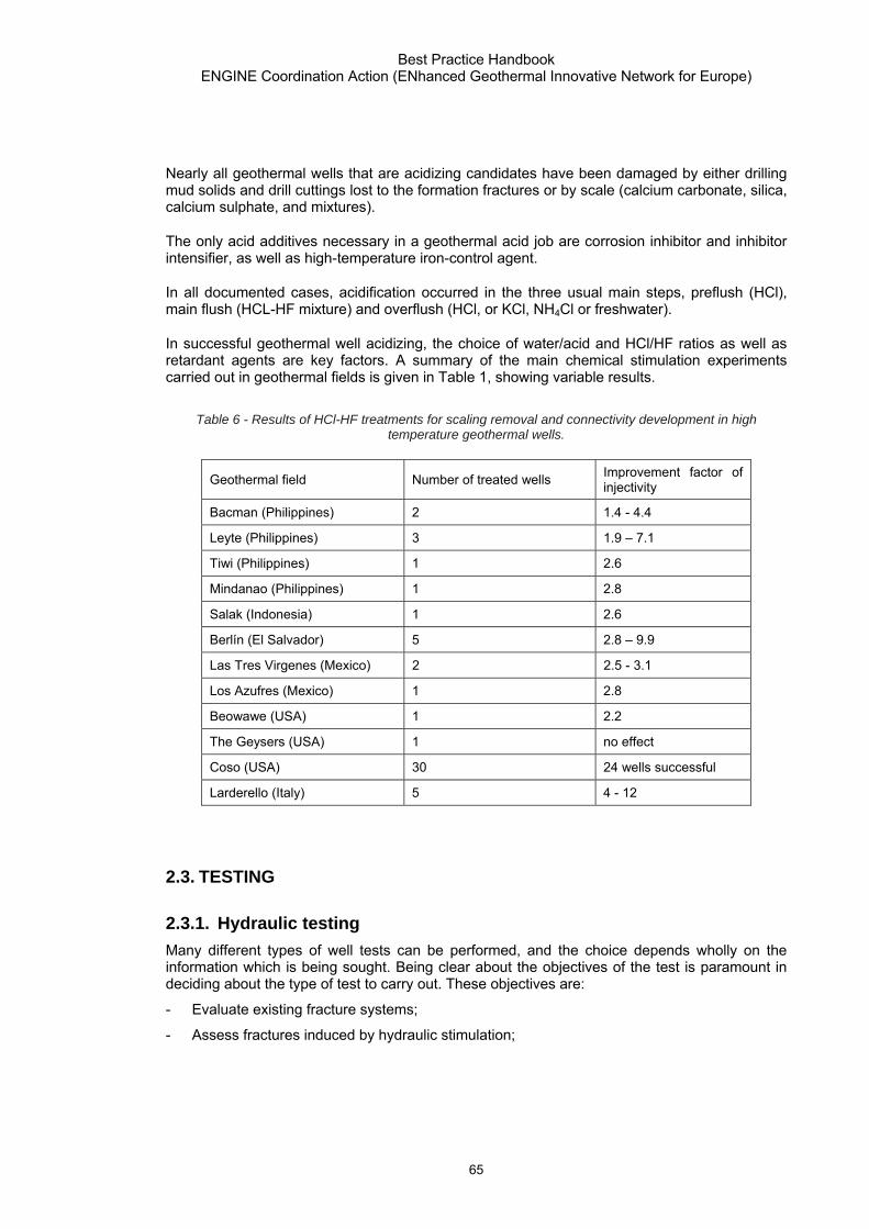
Best Practice Handbook ENGINE Coordination Action (ENhanced Geothermal Innovative Network for Europe)
65
Nearly all geothermal wells that are acidizing candidates have been damaged by either drilling mud solids and drill cuttings lost to the formation fractures or by scale (calcium carbonate, silica, calcium sulphate, and mixtures).
The only acid additives necessary in a geothermal acid job are corrosion inhibitor and inhibitor intensifier, as well as high-temperature iron-control agent.
In all documented cases, acidification occurred in the three usual main steps, preflush (HCl), main flush (HCL-HF mixture) and overflush (HCl, or KCl, NH4Cl or freshwater).
In successful geothermal well acidizing, the choice of water/acid and HCl/HF ratios as well as retardant agents are key factors. A summary of the main chemical stimulation experiments carried out in geothermal fields is given in Table 1, showing variable results.
Table 6 - Results of HCl-HF treatments for scaling removal and connectivity development in high temperature geothermal wells.
Geothermal field Number of treated wells Improvement factor of injectivity
Bacman (Philippines) 2 1.4 - 4.4
Leyte (Philippines) 3 1.9 – 7.1
Tiwi (Philippines) 1 2.6
Mindanao (Philippines) 1 2.8
Salak (Indonesia) 1 2.6
Berlín (El Salvador) 5 2.8 – 9.9
Las Tres Virgenes (Mexico) 2 2.5 - 3.1
Los Azufres (Mexico) 1 2.8
Beowawe (USA) 1 2.2
The Geysers (USA) 1 no effect
Coso (USA) 30 24 wells successful
Larderello (Italy) 5 4 - 12
2.3. TESTING
2.3.1. Hydraulic testing Many different types of well tests can be performed, and the choice depends wholly on the information which is being sought. Being clear about the objectives of the test is paramount in deciding about the type of test to carry out. These objectives are:
- Evaluate existing fracture systems;
- Assess fractures induced by hydraulic stimulation;

Best Practice Handbook ENGINE Coordination Action (ENhanced Geothermal Innovative Network for Europe)
66
- Investigate Matrix transport properties;
- Determine Reservoir boundaries;
- Reservoir compartmentalization.
A Pressure drawdown survey, in which the flowing bottomhole pressure is measured while the well is flowing, is a primary method of measuring productivity index (PI). Establishing a stable rate over a long period can be difficult, creating some uncertainty in the analysis.
Pressure build-up surveys measure the bottom hole pressure response during the shut in period which follows a pressure drawdown. This is useful for measuring reservoir properties and near well effects such as skin. In this test, the flow rate is known (zero).
Interference tests between two wells are used to estimate the transmissibility (kh/μ) of the formation in the interval between the wells. A pressure change is created at the active well by shutting in or opening up the well, and a pressure gauge in the closed-in observation well awaits a pressure response, the arrival time of which can be used to estimate transmissibility.
A pulse test is a version of the interference test, but attempts to provide enough information to allow the interpreter to eliminate the effects of noise and gauge drift in pressures (to which the interference test is prone) as measured at the observation well.
A Stepped flow and stimulation test basically is a small hydraulic stimulation, aimed at reducing near well bore inlet and outlet hydraulic impedances. It consists of injecting into a well at constant flow rate, and recording the pressure rise within time.
In a Multi-rate-pre-fracturing-hydraulic-test, the injection flow rate is increased in steps. In each step the flow is continued at constant rate until the injection pressure attains an asymptotic value. The test delivers valuable information on transmissibility, the significance of turbulence and details of fracture dilation Murphy et al. 1999.
A Multi-rate-post-fracture-performance-test is performed to determine the hydraulic properties of the stimulated fracture system. They are performed like the corresponding pre-fracture tests except that the flow rates are usually much higher, and the test duration is longer.

Best Practice Handbook ENGINE Coordination Action (ENhanced Geothermal Innovative Network for Europe)
67
Figure 11 - Injection Test after stimulation of the Soultz well GPK2 (T. Tischner).
Long-term injection and production tests in a single well are especially useful for determining the outer hydraulic boundary conditions of the stimulate fracture system. It can help to predict the long-term fluid loss from the reservoir during operation.
Generally, pressure differences during the test phase should be kept sufficiently small, in order to remain in the hydraulic mode instead of frac mode.
All off the aforementioned test procedures were developed in order to test wells which produce a single well fluid. In the more general case of multiphase flow, multiphase effects have to be taken into account in test interpretation. After Horne, 1995, it is almost always better to design a well test ahead of time, to avoid multiphase conditions during the test.
2.3.2. Tracer testing Tracer testing is an efficient method to detect and characterize hydraulic connections between deep geothermal wells, to understand the migration of injected and natural fluids, and to estimate their proportions in discharged fluids, their velocities, flow rates, residence times. Depending upon the tracer test methodology, useful information on transport properties and hydraulic connections essential for heat exchange or for fluid re-injection in geothermal reservoirs can be obtained from the data collected during such tests after their interpretation and modelling (Sanjuan et al., 2006, Ghergut et al., 2007).
Following the required information, several types of modelling approach can be used to analyze the tracer Return-Curve data from a slug injection: signal processing codes such TEMPO based on a model of dispersive transfer (Sanjuan et al., 2006) or using the moment analysis method (Shook, 2005), hydraulic or hydrodynamic codes such as SHEMAT (Blumenthal et al., 2007) or TOUGH2 (Pruess et al., 2000), coupled hydro-mechanical codes, etc.

Best Practice Handbook ENGINE Coordination Action (ENhanced Geothermal Innovative Network for Europe)
68
As the physicochemical behaviour of the tracers under given reservoir conditions (high salinity fluid, very low redox potential, low pH, etc.) is not always well known, the use of a minimum of two tracers (or comparison with a natural tracer or laboratory experiments) is recommended.
Among the tracers recommended in the literature for using at high temperature conditions, we can distinguish the following compounds:
- Liquid phase tracers: · naphthalene (di, tri)sulfonates (nds, nts, ns) family: 1,5-, 1,6-, 2,6-, 2,7-nds, 1,3,5- and
1,3,6-nts, 1- and 2-ns (Rose et al., 2001), · aromatic compounds: sodium benzoate or other benzoates (Adams et al., 1992).
Fluorobenzoic acids are water tracers widely used and preferred in oil reservoirs (J. Muller, IFE, pers. comm.),
· fluorescein (T < 260°C ; the other organic dyes are not recommended).
The use of inorganic and radioactive tracers is limited because of the high natural background of the halides (Cl, Br, I…) and difficulty in obtaining permits for radioactive tracers:
- Vapour or two-phase tracers: · alcohols (isopropanol, butan-2-ol, etc.) and hydrofluorocarbons (volatile low molecular
weight compounds R-134a (CF3CH2F) and R-23 (CHF3), Adams et al., 2001) as geothermal vapour-phase tracers, and perfluorocarbons as geothermal vapour-phase tracers. Perfluorocarbons are gas tracers widely used and preferred in oil reservoirs (J. Muller, IFE, pers. comm.),
· homologous series of short-chain aliphatic alcohols as geothermal two-phase tracers: ethanol, n-propanol (Adams et al., 2004; Mella et al., 2006a and b).
Naphthalene sulfonates have been or are used in numerous deep volcanic, granite and sedimentary geothermal fields. Alcohol tracers (isopropanol, butan-2-ol, etc.) have been used as steam-phase tracers in New Zealand (Lovelock, 2001) and at the Matsukawa vapour-dominated geothermal field in Japan (Fukuda et al., 2005). Halogenated alkanes and hydrofluorocarbons (R-134a and R-23) have been used as tracers in vapour-dominated systems such as The Geysers in the United States (Adams et al., 2001). Ethanol and n-propanol were successfully used as two-phase tracers at the Coso site in United States (Mella et al., 2006a and b).
Inter-well tracer tests using organic compounds such as Na-benzoate, 1,5-, 1,6-, 2,6 and 2,7-nds were conducted at the Soultz granite site during hydraulic stimulation operations (Sanjuan et al., 2006). A tracer test using fluorescein also accompanied a 5-month fluid circulation loop between GPK-3 (injection well) and GPK-2/GPK-4 (production wells) in 2005.
In the deep crystalline basement of the German KTB site, a combination of short-term and long-term tracings using uranine, nds compounds and tritiated water accompanied a long-term hydraulic and seismic testing program (Ghergut et al., 2007).
2.4. RESERVOIR ASSESSMENT MANAGEMENT AND MONITORING Once a geothermal reservoir has been opened up for energy extraction through one or several wells, a reservoir assessment should be performed, in order to estimate the amount of energy which will be extractable from the reservoir. To mine the available resource in a sustainable manner, a reservoir management or development plan should be implemented, which in most cases will have to be updated during the course of production to account for growing insight into

Best Practice Handbook ENGINE Coordination Action (ENhanced Geothermal Innovative Network for Europe)
69
the field and understanding of the reservoir. A monitoring program has to be implemented according to reservoir specific requirements.
2.4.1. Reservoir assessment Geothermal Reservoir assessment can be defined as the broadly based estimation of supplies of geothermal heat that might become available for use, given reasonable assumptions about technology, economics, governmental policy and environmental constraints (Muffler and Christiansen, 1978). Such reservoir assessment in terms of reserve estimation and valuation is currently not yet common practice within the geothermal community.
Like in the Mineral- and in the Hydrocarbon industry, any quantification of the reliability of the physical resource is generally performed using a classification into various classes: proven, probable and inferred reserves for example, with associated cumulative probabilities (P10, P50, P90). Clear criteria have been formulated by various Authors (Clothworthy et al., 2006, Sanyal et al., 2005) for such classifications.
Up to now there are no standards for a geothermal reservoir assessment, but various approaches exist. From these, only a volumetric reserve estimation, and a valuation based on numerical reservoir simulation can be considered as generally appropriate for geothermal reservoirs (Sanyal, 2005). The first Method gives a basic but sound estimation, which can be used in an early state, already ahead of an actual reservoir development. But it is associated with a certain degree of uncertainty. The second method heavily depends on comprehensive input data including an advanced production history, but it delivers the most accurate and reliable results.
In a volumetric reserve estimation, first the spatial extent and the thickness of the reservoir are determined from geophysical and geological exploration results, and, if applicable, the information from existing wells. In a second step, the “heat in place” about a certain reference level, for example ambient temperature or injection temperature, is calculated from reservoir volume and average temperature. After Sanyal, (2005) this is followed by estimating the recoverable heat energy reserves using a certain recovery factor, which describes the part of the heat in place, which can be produced at the well head. Electrical reserves are determined form thermal reserves und consideration of the relevant conversion efficiency. Finally the field capacity is calculated from the recoverable energy reserves, for an assumed power plant life and capacity factor. Generally, such a volumetric reserve estimation can be applied in several different ways which have been described and critically reviewed by various authors (Muffler, 1979, Sanyal et al., 2004, Sanyal and Henneberger 2004.) The aforementioned method is not applicable for steam dominated reservoirs, but for these cases an alternative formulation is given by Sanyal (2005).
A comprehensive review of numerical modelling procedures for geothermal reservoir assessment is given by Hochstein (1988). A numerical simulation starts with setting up a numerical model according to the geometry of a first conceptual reservoir model, which contains all information from previous assessments (static reservoir parameters, pressure and temperature data from wells and dynamic reservoir parameters from well tests). The model is calculated into an initial equilibrium. After that the induced heat and mass transfer is computed for the period of known production. The computed time variable parameters are compared with the observed values, and if necessary, the model (permeability distribution and/or model geometry) are modified in order for the simulation results to best fit the production history. A numerical simulation is obviously only relevant and applicable for reserves which were classified as proven.

Best Practice Handbook ENGINE Coordination Action (ENhanced Geothermal Innovative Network for Europe)
70
Since the volumetric reserve calculations are prone to overestimation, they should be based on conservative assumptions of the input parameters (Sanyal et al., 2005). It is generally stated (Clothworthy et al., 2006, Sanyal et al., 2005) that reserves should only be classified as proven, if, and only if prospects for the commercial productivity from the reservoir have been demonstrated.
2.4.2. Reservoir management For each geothermal system and for each mode of extraction there exists a certain level of maximum energy production E0, below which it will be possible to maintain constant energy production for a very long time. E0 is not known a priori, but can be estimated, by modelling, on the basis of available data, (Axelsson et al. 2004). In many cases several decades of experience have shown that by maintaining the production below a certain limit, a geothermal system reaches a certain balance, which may be maintained for a long time. The overall generating capacity of geothermal systems is often poorly known, and they often respond unexpectedly to long term production. Careful monitoring and modelling as well as energy efficient utilization are essential ingredients of a sustainable geothermal reservoir management.
The reason for overexploitation of geothermal reservoirs often is a poor understanding of the geothermal system due to lack of monitoring and data collection. Rybach (2007), performed FE calculations at EGS Models, investigating two different exploitation scenarios. These investigations showed that with lower extraction rates, longevity of the resource, and thus sustainable production, can be achieved and still generate as much energy as from excessive production.
In order to maintain a sustainable production Management of geothermal fields should always include common management of nearby wells which might be utilized by different users. The negative experiences of the Geysers field, USA, with 22 power plants and a cumulative capacity of 1531 MW should be avoided, where a drastic pressure drop in the field caused the steam production to be insufficient for all the power plants and production declined steadily. The pressure drawdown due to overexploitation of the Geysers geothermal field could meanwhile notably be diminished since the water reinjection programme has started.
2.4.3. Corrosion and scaling Alkalinity and CO2 together with temperature control the corrosion in the geothermal production wells. It is a general belief that the corrosion is usually controlled by the formation of protective films of corrosion products or an efficient corrosion inhibitor and that the corrosion rate is low. The corrosion in the injection well is currently controlled by applying a corrosion inhibitor and oxygen scavengers.
With regard to CaCO3 and SiO2 scaling it will be advantageous to reduce the pH in the injection water from ca. 4.8 to 4.3. This will affect the corrosion rate in the injection well, and it is recommended to carry out an experimental program to evaluate the effect this will have on corrosion. It has to be documented that the corrosion inhibition will be sufficiently effective at the lower pH.
There is a range of monitoring systems that can be used for online monitoring of corrosion rates. The challenge is to place them at the most relevant positions. Weight loss coupons can be applied during circulation tests. It is also recommended that iron counts are carried out regularly. It might also be worthwhile to evaluate the possibility of using hydrogen monitoring as corrosion surveillance on the production wells.

Best Practice Handbook ENGINE Coordination Action (ENhanced Geothermal Innovative Network for Europe)
71
2.4.4. Reservoir monitoring Monitoring of geothermal fields and their production currently is no standard procedure. Goal, purpose and design of any geothermal monitoring program depend to a great deal on the particular geological environment and production conditions. Potential monitoring parameters are the conditions of state, reservoir pressure and temperature, fluid chemistry, flow rate (spinner surveys), seismicity, gravity and the electrical potential. An adequate monitoring program helps to avoid overexploitation of the geothermal reservoir, leads to a better understanding of the geothermal system and allow a more reliable reservoir modelling (Axelsson et al., 2004).
Monitoring of the chemical composition of water and steam discharged from wells in exploited geothermal fields provides valuable information on the response of the reservoir to the production load (Arnorsson and Gudmundsson, 2003). Withdrawal of deep reservoir fluid generally induces recharge, which may alter the chemistry of the fluid, especially if a significant portion of the recharge water has a very different chemistry. Monitoring of the dilution trends can provide information about the rate of lateral movement of the invasion front.
Geophysical monitoring can be a useful tool, helping to understand pathways within the reservoir as well as fluid migration, and thus aid in optimizing reservoir exploitation strategies (Rivas et al., 2005). Apart from these purposes, seismic monitoring has also proven to be a potentially very useful exploration tool. But this has up to now mainly been reported from volcanic environments. The Analysis for fracture density can indicate potentially fractured areas as exploration targets (Simiyu, 2000). Axelsson et al. (2006) report on a case, where earthquakes at a much deeper depth than the injection horizon indicated that a hydraulic connection exists to deeper Horizons. This meant that the source area for the particular field was much bigger that assumed up to that point, and the field had the potential for much wider geothermal use.
Any monitoring of a geothermal reservoir should commence at the time, the actual production begins, at the latest (Hunt, 2000). It should be performed frequently enough, that natural variations can be distinguished from exploitation induced changes. The data have to be archived and documented in such a way, that they are accessible for the potentially changing interpretation personnel over the entire field life.


Best Practice Handbook ENGINE Coordination Action (ENhanced innovative Network for Europe
73
3. Exploitation: Best Practices and innovation Needs
3.1. OVERVIEW Power generation is the main option considered for geothermal development. In contrast to heat, the market for power supply is widely developed and usually accessible; furthermore national regulations usually foresee economic incentives to promote renewable energies in terms of guaranteed feed-in tariffs for electricity, quota systems and/or investment subsidies. Depending upon the available temperature, existing geothermal power plants are either steam condensing plants or binary plants. Steam condensing plants are traditionally used when the geothermal temperature exceeds 180°C. Depending on geothermal fluid temperature and pressure, they can be designed as dry steam, single flash or double flash units. Binary plants are used for geothermal supply temperatures of 90-180°C. Site specific optimization in terms of energy use can lead to plant concepts combining a steam condensing plant with binary units. Due to high initial investments and low heat-to-power conversion efficiencies because of the temperatures involved, geothermal power plant economics tend to be marginal even if load factors higher than 95% make a continuous power supply feasible.
In order to improve geothermal plant economics, there is the need to utilize more heat of the produced fluid, and hence operate a geothermal plant providing power and heat by using the residual heat in the brine and/or the waste heat from the conversion process. At present geothermal cogeneration plants use the heat of the brine exclusively downstream, or in parallel to the power plant. Electricity is thereby usually generated at times where there is limited or no demand for heat. In essence, heat is supplied when needed, usually for 30% of the time, and power for the remaining 70%.
Geothermal plant economics can be improved further by constructing hybrid plants such as a combined geothermal and gas plant. Such a plant has the advantage of CO2 emissions reductions resulting from utilizing a renewable energy form together with the positive economics and high conversion efficiency of a gas power plant. Other hybrid concepts are also possible such as the combination of biomass and geothermal energy. Hybrid concepts generally can utilize more of the heat potential of the geothermal reservoirs and waste heat of other processes.
In hydrothermal fields, geothermal condensing plants usually consume 6-8 kg steam per kWh(e), have 10-20% energy efficiency, and capacities ranging between 20-133 MW(e) for dry steam fields and 10-55 MW(e) for two phase fields. Investment costs amount at 1000-2200 €/kW(e) and overall electricity generation costs amount at 0.04-0.06 €/kWh(e) including capital amortization. Geothermal binary plants investment costs amount at 1500-3000 €/kW(e) and overall electricity generation costs amount at 0.05-0.07 €/kWh(e) including capital amortization.
Depending on the site, Enhanced Geothermal System plants capital costs may vary from 10,000 €/kW(e) to 26,000 €/kW(e) and overall power generation costs may vary between 0.17 €/kWh(e) and 0.35 €/kWh(e) including capital amortization. Heat-to-power conversion efficiency is estimated between 7% and 12%, governed by the conversion efficiency of binary plants which depends on the temperature of the heat carrier fluid. Further, the produced power is reduced by the power consumption of the downhole pump. Power generation costs can be effectively reduced by the above named measures of additional heat provision or implementing hybrid plants.

Best Practice Handbook ENGINE Coordination Action (ENhanced Geothermal Innovative Network for Europe)
74
The main advantage of an EGS plant is that it can basically be engineered everywhere, with the ability to control the main operating parameters such as temperature, reservoir volume, fluid chemistry, flow rate and pressure. Related costs however, will most likely be close to the upper end of the scale, or around 25,000 €/kW(e).
Table 7 - Geothermal Systems Overview
Type of Resources Hydrothermal Fields Enhanced Geothermal Systems
Supercritical Reservoirs & Magma
Chamber
Location Volcanic areas, Deep Sedimentary Basins Everywhere Volcanic areas only
Commercially Available Yes No No
Power Plant Range 0.3 – 133 MWe 1 – 6 MWe 40 – 100 MWe
Heat carrier Natural Steam, Two Phase or Liquid Water Injected water Supercritical water
Heat-to-Power Conversion Efficiency 7% - 20% 7% - 12% 30%
Environmental aspects liquid phase chemistry,
H2S & salts traces in the steam
Micro-seismic activity unknown
Other Features Cogeneration, >90% capacity factor
Cogeneration, >90% capacity factor unknown
Costs, power generation 1000 – 3000 €/kW(e) 0,04-0,07 €/kWh(e)
10000 - 26000 €/kW(e)
0,17-0,35 €/kWh(e) unknown
Costs, heat supply 100 – 300 €/kW(th) 0,004-0,007 €/kWh(th)
1000 - 2600 €/kW(th)0,017-0,035 €/kWh(th) unknown
Commercial Status well deployed Experimental Plants Basic Research
3.2. EXPLOITATION CYCLE The fluid supply and disposal system includes production wells, fluid pipelines and reinjection wells. Well locations, paths and specifications (depth, hole-diameters, casing string, downhole pumps if any) are based on the results of the exploration works taking also into consideration new information acquired from subsequent well drilling and testing. A thorough well testing

Best Practice Handbook ENGINE Coordination Action (ENhanced Geothermal Innovative Network for Europe)
75
program is necessary to identify well production characteristics and reservoir properties. It includes production tests, injection tests, interference tests and tracers. The number of production wells depends upon the necessary geothermal fluid mass flow rate output, and on the need to tap enough proven stored heat resources, for a given plant size. A reservoir engineering study is necessary in order to predict well output behaviour during long term exploitation (pressure, temperature and chemistry transients), which is updated as new data comes in.
Depending on the plant design incl. well completion design (see chapter 2), main equipment used includes downhole pumps, well-head assembly with valves and controls, sand/particles removal equipment, silencers, separators, steam moisture separators, two phase pipelines, steam lines, hot water (brine) lines, main heat exchanger, brine booster pumps, reinjection pumps as well as scale/corrosion inhibitors injection equipment.
3.2.1. Piping Pre-insulated or on site insulated pipes are used to transport geothermal fluid from the production wells to the plant. The transmission pipelines are designed for maximum pressure drop of 0,5-1,0 bars per km. Most common pipe material is carbon steel or in case of no H2S and temperature up to 138°C flexible copper. Insulation is usually either polyurethane foam protected externally by polyethylene or aluminium sheet or stainless steel. Other materials include fibreglass, polypropylene, polybuthylene, polyethylene and other plastics for small size piping and/or lower temperatures. For extreme corrosive brines and high temperature applications, resistant steel alloys (>25% chromium) or titanium are used.
3.2.2. Production pumps When self flow is not sufficient to guarantee the plant economics, the installation of a production pump is necessary. Depending on the setting depth and water temperature different types of pumps are currently in use. They include line shaft pumps, submersible pumps and turbopumps. The shaft driven submersible pump comprises a multistage downhole centrifugal pump and surface mounted motor plus long drive assembly extending from the motor to the pump. This pump is used for shallow depths down to 200m, and 80-130°C temperature. Electric submersible pumps consist of a multistage centrifugal pump connected to an electrical motor, directly set in the well on the bottom of the pump. They can be used in larger depths and have a capacity up to 2,000 lt/min, about seven times more that of the shaft driven pumps. As 50% of the pump breakdowns are due to electrical problems, any water infiltration must be eliminated by the waterproof design for the motor. In the case of bottom hole high fluid temperature (200°C), special electric oil filled motors are available. Submersible turbopumps have a hydraulic part driven by a turbine, itself driven by pressurised geothermal water circulation aided by a surface pump. It has lower energy efficiency, but needs less maintenance.
3.2.3. Reinjection pumps To minimize environmental impact and enhance fluid recharge into the geothermal system during exploitation, reinjection of waste water becomes a model feature of all geothermal developments. As a standard practice, reinjection wells are located at lower elevation than the production wells to eliminate the use of reinjection pumps. However in cases where this is not applicable because of topographic constraints and reservoir characteristics, the use of reinjection pumps becomes part of the production facilities. Usually, horizontal pumps are adopted for this purpose. They have a capacity up to 1,500 l/min and operate with water

Best Practice Handbook ENGINE Coordination Action (ENhanced Geothermal Innovative Network for Europe)
76
temperature up to 80°C. A photo of an injection pumping system at the Berlin Geothermal field, in El Salvador is shown in Figure 12.
Figure 12 - View of injection pumping system at Berlin Geothermal field, in El Salvador.
3.2.4. Heat exchangers Two types of heat exchangers are used, plate heat exchangers and shell-and-tube. Materials used depend on the fluid corrosion tendency and may include stainless steel, or titanium. A plate heat exchanger consists of a pack of metal plates with portholes for the passage of the two fluids. The plates are fitted with a gasket which seals the channel and directs the fluid in two alternate directions. Different solutions (plate corrugations or wiring grid between plates) promote fluid turbulence to reduce fouling between the plates. The plate pack is assembled between a frame plate and a pressure plate by means of tightening bolts. The typical performance limits are temperatures up to 130°C and pressures up to 25bar. The brazed plate heat exchanger is a variation on the normal plate heat exchanger and consists of a pack of metal plates fitted without interplate gaskets. The pack of plates is tightened by bolts between a frame plate and a pressure plate; special gaskets are installed between the external plates and the pack of plates. The plates are brazed together in a vacuum oven to form a compact pressure-resistant unit. The turbulence created by the plate corrugations promotes heat transfer and reduces fouling. The system is designed to work up to 225°C and 30bar. The shell and tube heat exchanger consists of a series of tubes surrounded by an enclosing shell. The tubes may have a U-tube configuration but in order to facilitate cleaning of the tubes, the solution with

Best Practice Handbook ENGINE Coordination Action (ENhanced Geothermal Innovative Network for Europe)
77
straight tubes and removable heads at both ends is usually adopted. Operating limits are 130°C and 25bar.
3.2.5. Inhibitors injecting equipment Effective protection from corrosion and scaling can take place by injecting into the fluid inhibitors based on quaternary amines, whose filming capacity ensures an optimum protection of the casing. Chemical inhibition systems, such as down-hole injection lines, have been installed in production wells at more than 40 plants in Europe.
3.3. POWER GENERATION
3.3.1. Condensing Plants 94% of the total generated power globally is derived by steam flash plants, the majority of which use condensing turbines, which in practice yield twice as much power output than the atmospheric exhaust ones. In a condensing plant the steam is condensed at the turbine outlet, at exhaust pressure of 0.10-0.12 bar, which results in improved cycle efficiency. Specific steam consumption of 7-8 kg/kWhe is typical for non condensable gases content of 1%.
Production from water dominated fields requires the use of steam/water separators with either single or double flash cycles. In single flash plants, typical separation pressures are 5-7 bars optimizing the inlet pressure to the turbine. As the separated water is of 150-170°C temperature and has high energy content, it can be flashed further at a lower pressure of 2-2.5 bars and either supply the second stage of the turbine or feed a second turbine operating at lower pressure. The magnitude of separation pressure, and the decision of whether to use single or double flash units, depends on the scaling tendency of the fluid, e.g. higher separation pressures may be necessary in order to control silica or calcite scaling in the separator and brine lines.
Main equipment items may include steam scrubbers, wet steam turbines, dual admission turbines, condenser, controls and remote control, condensate pumps, cooling water pumps, steam jet ejector, compressors, vacuum pumps, cooling towers, gas extraction equipment, hydrogen sulphide and mercury abatement equipment.
In flash plants, as plenty of steam condensate is available for make up water, the standard technology adopted almost exclusively is cost effective direct contact condensers coupled with wet cooling towers. However, if the plant is located close to the sea or river, where water availability in large quantities is not a problem, the direct contact condensers can be supplied by surface water in once-through systems, leading to improved conversion efficiency.
The flow charts of geothermal condensing plants are shown in Figures 13 and 14 for single flash and double flash plants respectively.

Best Practice Handbook ENGINE Coordination Action (ENhanced Geothermal Innovative Network for Europe)
78
Figure 13 - Flow chart of a single flash condensing geothermal power plant.
Figure 14 - Flow chart of a double flash condensing geothermal power plant.
3.3.2. Binary Plants In case of geothermal fluid temperature less than 150ºC, the most common technology used are binary Organic Rankine Cycle (ORC) machines. In an ORC machine, the geothermal fluid transfers thermal energy to a closed loop of circulating fluid, or working fluid, through a heat exchanger. Typical working fluids used in ORC machines are either hydrocarbons (isobutane or

Best Practice Handbook ENGINE Coordination Action (ENhanced Geothermal Innovative Network for Europe)
79
isopentane) or fluor-hydrocarbons, which operate at relatively low pressures. The circulating fluid evaporates within the geothermal heat exchanger mentioned above, and from there its vapour is conveyed into a condensing turbine for power generation. The condenser, can either be water cooled (cooled by surface water or by water from a cooling tower), or air cooled. Then, the liquid working fluid is pumped to the geothermal heat exchanger and the cycle is repeated. The whole process of a geothermal power plant with Rankine cycle is presented in Figure 15.
Figure 15 - Schematic presentation of a geothermal water cooled ORC power plant.
A similar cycle using a mixture of water and ammonia as working fluid may also be used, with the corresponding process termed as Kalina. Although Kalina cycle had initially high expectations in terms of conversion efficiency and costs, operation of existing plants indicate more or less similar performance with ORC machines.
Present geothermal binary plants are designed for cost effective operation with entering geothermal fluid temperature of at least 90°C. Due to the low temperature of the geothermal heat source and their small size, binary plants (ORC or Kalina) have higher
capital costs per unit of installed power, compared with traditional condensing geothermal power plants.
ORC plants are computer controlled with automatic start-up. They require no supervision during operation, monitored and controlled remotely through a telephone line, or operated by part time semi-skilled personnel. They operate in a variety of load conditions, such as base load, peek load, fluctuating load, low load down to 0-25% of rate power. Conversion efficiency depends on both heat supply temperature and load, usually varying from 6.5%-15% for geothermal fluids of 90ºC-150ºC.
Three main cooling options are used: a) surface water (once-through systems), b) wet type cooling towers, and c) dry type cooling towers. Cooling with surface water yields the lowest condensing pressure and temperature and the highest conversion efficiency, followed by wet cooling towers, and then by dry cooling towers. Regarding the need for cold water supply, the order is reversed. Typical values are 970 t/h, 30 t/h and zero t/h respectively per MWe of installed power. In terms of costs, once through cooling may require both high capital costs and electricity consumption for transporting water. Dry cooling is the most expensive option due to the much higher heat capacity and heat transfer coefficient of water compared with ambient air. A dry cooling tower for a binary power plant of high conversion efficiency may cost 10 times more than its wet counterpart, which may result in raising overall power plant costs by 50%. In binary plants, where the more expensive shell-and-tube or plate heat exchangers are used as

Best Practice Handbook ENGINE Coordination Action (ENhanced Geothermal Innovative Network for Europe)
80
surface condensers, the selection of the cooling system type is governed by water availability, local water use regulations and economics.
3.3.3. Heating applications Heating applications using residual or waste heat include space and district heating, heating of soil and greenhouses, sea farming and heating of low temperature industrial processes such as drying, seawater desalination, and washing. The energy output of a geothermal low temperature heating plant can be improved by water source heat pumps.
3.4. MONITORING AND FIELD MANAGEMENT Defining a monitoring program during exploitation and allocating the necessary budget is important in order to study the evolution of reservoir and fluid parameters over time, and further decide on the exploitation strategy of the geothermal field, e.g. increase or decrease production rates, change the location of reinjection wells, drilling additional wells, treating the fluid with chemical agents in order to prevent scaling or corrosion, etc. A geophysical and geochemical monitoring program is essential. Geophysical parameters monitored should include micro-earthquakes, resistivity and gravity data with the aim to predict possible future environmental impact (micro-earthquakes evolution and subsidence if any), as well as the fluid changes that may take place within the geothermal reservoir. The latter should include chemistry transients of the produced geo-fluids, aiming in predicting future evolution of its scaling or corrosion tendency. In addition pressure, flow rate, temperature/enthalpy transients at the production and reinjection wells should be monitored. The data collected from the above monitoring program, should feed an integrated reservoir engineering and computer simulation task, which should direct the future exploitation strategy of the geothermal field.
An important part to be also monitored are the thermal manifestations, which must include evolution of hot springs and fumaroles, steaming ground, hydrothermal evidence, while for environmental purposes monitoring parameters should include the chemistry of nearby water streams or rivers, the air quality around the wells and plants, as well as the noise level.
Geothermal plants may need periodic maintenance work in order to eliminate scale and recondition the boreholes. Methods used are mechanical cleaning with a scraping tricone tool hanging from a rod assembly, hydraulic jetting with a coil-tubing unit of small diameter, and combined hydraulic-mechanical processes.
The main objective of field management is to sustain production at desired levels. Some of the field management practices include:
(a) drilling additional production wells in new areas to offset the generation loss from dying wells due to cold surface water inflow or reinjection returns,
(b) casing-off acid zones or establishing downhole corrosion mitigation to eliminate problems associated with inflow of cold acid fluids,
(c) moving injection wells or limiting injection rate in order to minimize injection breakthrough,
(d) work-over drilling and acidizing to dissolve silica scales encountered in the injection wells,
(e) installation of calcite inhibition system whereby inhibitors are injected to slow down calcite deposition in production wells

Best Practice Handbook ENGINE Coordination Action (ENhanced Geothermal Innovative Network for Europe)
81
(f) convert injection from cold to hot, in order to minimize scaling in the injection lines, wellbore and reservoir,
(g) perforation of cased-off permeable zones for additional production,
(h) upgrade production facilities to address changing reservoir conditions by including "brine-scrubbing" of steam, and by improving brine separation efficiency,
(i) installation of steam washing and solids removal trapping facilities along the steamline to catch the fine solids carryover from drying steam reservoirs.
(j) optimizing the use of thermal energy by modifying or updating the equipment parts in order to adapt them to new exploitation conditions (ejectors, large pressure loss in the pipes, etc.)
3.5. RESEARCH AND DEVELOPMENT NEEDS As the technical feasibility for EGS exploitation has been proven by the Soultz European Hot Dry Rock project, further research should focus towards reducing the output unit energy costs from EGS plants, as this is the main barrier towards their large scale exploitation. A European research and demonstration project proving the economical feasibility of EGS plants is necessary in order to stimulate large scale development and effectively contribute to the EU renewable energy objectives of 2020.

Best Practice Handbook ENGINE Coordination Action (ENhanced innovative Network for Europe
83
4. Environmental and socioeconomic impact
Geothermal energy, as a renewable energy form, is an indigenous energy source and its use results in stimulating local development and increasing local employment. In addition, as it replaces imported fossil fuels it results in improving the trade balance of the European Union and reducing carbon dioxide emissions. As EGS plants have practically zero carbon emissions per kilowatt-hour of electricity generated, the increase in deployment of geothermal energy will have a large net positive effect on the environment in comparison with the development of fossil fuels, which is in alignment with the Kyoto targets. In addition, geothermal power plants have considerably lower sulphur emissions rates than fossil-fuel alternatives, including natural gas.
However, no energy source is completely free of adverse impacts on the environment. As sustainable geothermal energy provision has to result in benefits to the environment compared to other alternatives, environmental impacts need to be precisely assessed. Therefore, communicating environmental impacts and working on diminishing them is an integral part for further developing geothermal energy.
4.1. ENVIRONMENTAL CONCERNS
4.1.1. Introduction Although geothermal energy is a renewable energy form and friendly to the environment, its large scale development is not entirely free from local environmental impact. This impact depends on practices of the geothermal contractor and on geothermal plant design. The most critical environmental problems are associated with the chemistry of the geothermal fluids, which can be chemically aggressive brines, as the hot water usually has a lot of minerals dissolved. The steam evaporationg from the brine as well as the water itself can have harmful effects to the environment and become a nuisance for the local population, if not properly taken care of. These probelmes normally only occur, if water/steam is only produced but not reinjected into the subsurface. Reinjecting the cooled, liquid phase and proper plant design to eliminate the effect of non-condensable gases present in the steam usually solves these problems. In some cases, especially during the early exploration phase, escape of steam or hot geothermal brine to the surface or air may be inevitable, which may cause limited localized damages to plants, or a characteristic smell of sulphur in the vicinity of the wells. Other impact may be the appearance of micro-earthquakes, which generally do not not pose a threat to people and structures, but they may worry local society. Nonetheless, these concerns have to be taken seriously and to be properly addressed. Some geothermal projects had to be abandoned due to strong opposition from local community, associated with the above effects of geothermal development.
4.1.2. Low Enthalpy Hydrothermal Fields The positive environmental impact of all geothermal plants is attributed to foregone CO2 and other emissions (e.g. carbon monoxide, carbon particles, nitrogen oxides, sulfur oxides), had the same quantity of energy been produced by fossil fuels. However, in some low enthalpy geothermal fields the deep hot water may contain dissolved CO2 in the form of bicarbonate ions. When these fluids are brought to the surface and their pressure is lowered, they tend to deposit calcite and release CO2. Such fluids are usually located at the margins of larger hydrothermal systems. The CO2 emissions from a geothermal field can be reduced by engineering the exploitation scheme accordingly. For example, maximizing the energy extracted from a given

Best Practice Handbook ENGINE Coordination Action (ENhanced Geothermal Innovative Network for Europe)
84
flow rate by placing the users in cascade, results in minimum CO2 emissions. In agricultural uses, the geothermal CO2 can be directly released within the greenhouse, in order to increase the growth rate of the plants and save fossil fuels. Other impact from long term low enthalpy geothermal utilization may be the dropping of water level of near surface aquifers and the flow reduction or dry-up of nearby springs and shallow water wells. All these problems can be avoided by reinjecting the cooled liquid.
4.1.3. High Enthalpy Hydrothermal Fields In high enthalpy hydrothermal systems, the steam phase of the geothermal fluid frequently contains small quantities of non-condensable CO2, the quantity of which varies from field to field but it is limited to a few percentage units, usually in the range 0,05-5%. CO2 emissions from geothermal power plants compared with conventional power plants are presented in Table 8. When comparing these figures, the natural degassing of CO2 from the subsurface has to be deducted which occurs everywhere on Earth, especially in places with naturla hot springs.
Table 8 - Comparison of CO2 emissions between geothermal and conventional power plants.
Location Net Power, MW(e)
CO2, % w/w
Conversion efficiency
CO2 emissions, kg / kWh(e)
Net effect, kg CO2/ kWh(e)
Milos, Greece - 1,5 % 19,1 %(*) 0,10 0 Upper Rhine Graben** 0,85 - 11% 0,06 0,06 North German Basin** 0,85 - 11% 0,08 0,08 Lago 8,30 1,7 % 13,3% 0,16 0 Monterotondo 8,19 1,6 % 13,2% 0,16 0 Molinetto 17,95 4 % 17,7% 0,29 0 Gabbro 16,52 12 % 14,6% 1,05 0 Radicondou 36,89 5 % 19,0% 0,34 0 Travale 40,75 5 % 21,0% 0,31 0 Natural Gas 50% 0,38 0,38 Diesel Oil 33% 0,75 0,75 Coal 33% 0,90 0,90 (*) steam phase only (**) life cycle assessment (LCA) - ecobalance
Additional and more intense effects to local environment are associated with the chemistry of the steam, which may contain non condensable gases, such as CO2, traces of H2S and entrained silica or other dissolved solids in the liquid phase. In Milos, Greece,, sulfur smell and silica scale on car windows were two of the three factors that finally forced operators to abandon the pilot plant after only 2 years of operation, as it had completely lost acceptance by the local population.
These problems can be effectively alleviated by minimizing the steam losses from the geothermal plant (in fact steam losses should be allowed only at the safety valves), and by conveying the non-condensable gases to the cooling tower draft, where they are diluted by large quantities of air. If these measures fail to limit the H2S concentration in the air below the smelling threshold, then an H2S treatment plant should be installed, such as the “Amis” technology developed by Enel already installed in 16 power plants.
Another very effective way is to keep all geothermal fluid under pressure at a closed circuit and reinject all liquid, steam and gas phases back to the deep reservoir, and using a binary plant for

Best Practice Handbook ENGINE Coordination Action (ENhanced Geothermal Innovative Network for Europe)
85
power generation. The application of this plant design however, is limited by the availability of dowhnole pumps suitable for the high temperature, pressure and chemistry of the geothermal fluid.
Other problems associated with high enthalpy hydrothermal plants are:
- Micro-seismic activity: it is of small magnitude, usually only registered by the seismographs and does not pose any threat to buildings or structures. Normally, seismicity induced by human intervention such as mining, gas exploitation, the building of dams for hydropower or geothermal exploration and exploitation activities, mostly – although not exclusively – occurs in tectonically active regions, where natural seismicity is the rule rather than the exception. Thus most of the seismic activity associated with geothermal developments takes place in existing and often known fault and fracture zones. Nonetheless, the magnitude of seismic events can become critical and cause some regional unrest among the population if measures to prevent such problems are not taken in advance. Such preventive measures have to follow two paths: those that reduce the number and magnitude of seismic events and the others that educate the local population and policy makers, gain their support and reduce the risk of social problems.
- Understanding seismicity is a complicated venture, which has kept thousands of scientists busy for many decades. Even though the seismic risks associated with the exploitation of geothermal resources have been know for a long time, measures to mitigate induced seismicity have only been taken in very few cases, and only sometimes had the desired success. Most case studies in the geothermal context concern Enhganced Geothermal Sysetems, which are addressed in subchapter 4.1.4 The most prominent example of seismicity caused by fluid reinjection (and extraction) is probably The Geysers in California, USA (Majer and Peterson, 2007), where micro-earthquakes even of M>4 have been monitored and documented for most of its production history.
Ways to avoid damage and public concern at The Geysers have been: · Constant monitoring of the seismic activity in the entire area, not just around the well. · Intelligent injection control reducing risk of large events (M>3). This implies a proper
balance of fluid injection and extraction rates.
Moreover, the seismic history and local geology have to be known. If an active fault cuts the reservoir, seismic events are more likely to occur compared to tectonically quiet regions. In addition, densely populated areas in the vicinity of the well are ususally prone to increased public awareness and concerns, which requires even more public communication and perhaps a reduction in injection activity to maintain long-term acceptance. In the case of The Geysers, the low population density and the naturally occurring seismicity of the region also help to keep acceptance levels sufficiently high.
- Soil subsidence: it is of one or more meters magnitude and should occur in the centre of the production zone after many years of exploitation and withdrawal of large quantities of geothermal fluids. Horizontal soil movements are also possible. In Wairakei, New Zealand, a subsidence zone more than 2 meters deep covering an area of 1 km2 has been observed at the borders of the production zone after 20 years of exploitation,. Maximum reported subsidence was >9 meters. The problem is solved by reinjecting all the separated liquid phase and the steam condensate back to the geothermal reservoir from the very beginning of the project. During the plant design phase, care should be taken not to locate in the subsidence zone any buildings, pipelines or other structures. Furthermore, monitoring micro-gravity transients and regular topographic surveys are necessary during exploitation, in order to study the evolution of the subsidence zone.

Best Practice Handbook ENGINE Coordination Action (ENhanced Geothermal Innovative Network for Europe)
86
- Noise: can be severe and a nuisance to local residents who live close to the geothermal plant. In Milos, noise was one of the three factors leading to complaints by the local population during the short time of operation of the pilot plant. It is countered by proper plant engineering (e.g. avoiding noisy equipment) and by placing noise barriers if necessary.
- Damage to local flora: it occurs every time steam or hot geothermal fluids are released on local plants. It happens due to the high temperature and salinity of the geothermal fluids. This is usually not a problem when fluids are reinjected.Care should be taken during the exploration and field development phases for proper disposal of fluids delivered to the surface. Removal of damaged trees, plants, etc., may be necessary for improving local aesthetics, while compensations for damaged property should be foreseen.
- Aesthetics: Some direct use installations have no visual impact. Thermal heating plants can be integrated within the urban landscape since all equipment including the pipes of large district heating systems can be placed underground. Other uses of geothermal energy such as horticulture and fish farming tend to have relatively minor visual appearance, depending on the scale of development and the nature of the terrain in which these activities occur. Electrical generation plant can have relatively minor visual impact and certainly no greater than the conventional fossil fuel burning plants. With proper design, the geothermal plant can be transformed to a tourist attraction, such as in cases of Larderello.
- Heat pollution: when waste heat is released to local environment. This problem can be avoided by minimizing the waste heat disposed to the surface from the plant, i.e., proper cooling. Effective solutions are reinjection, and geothermal heat and power cogeneration.
- Changes in surface flow of water: some changes in the thermal manifestations can occur especially in reservoir exploitation, the hot spring and fumaroles intensity depend on the pressure drawdown of the reservoir and it is more evident when these thermal manifestations are directly connected to the reservoir. Some hydrothermal eruptions could be also correlated with the exploitation. Actually the “Craters of the Moon” in the Wairaki field New Zealand is the only evidence of hydrothermal eruption correlated with the exploitation.
4.1.4. Enhanced Geothermal Systems In the case of enhanced geothermal systems, where water is initially injected and then circulates through the system, not only zero CO2 emissions are much less, but also the problems regarding water chemistry will be less severe, as water chemistry can be strongly influenced from above, even if it only dilutes existing fluids. If an existing fluid system is enhanced to increase permeability, all the problems mentioned for the other hydrothermal systems may apply.
The most problematic side-effect of enhancing geothermal reservoirs by hydraulic stimulation is the potential to generate earthquakes, which may become detrimental for the further development of project. In the case of EGS, fluid injection is carried out to enhance rock permeability and recover heat from the rock, often at depths greater than 2 km. During the process of opening permeable space in the rock or during subsequent exploitation of the reservoir, stress patterns in the rock may change and produce microseismic events. In almost all cases, these events have been of such low magnitude that they are not felt at the surface by the local population. The events usually have so little energy relative to natural earthquakes, with relatively short duration, high frequency and very low amplitude, that they pass unnoticed. However, there have been some significant seismic events arising from short-term stimulation operations at EGS. These include the 2003 M=3.7 event at the Cooper basin EGS site, Australia (Baisch et al., 2006) and the most recent event in December 2006 with M=3.4 in Basel (Switzerland). The project in Basel was put on preliminary halt. Similarly, the stimulation programme at Soultz-sous-Forêts further north in the Rhine Graben had to be changed due to

Best Practice Handbook ENGINE Coordination Action (ENhanced Geothermal Innovative Network for Europe)
87
complaints by local residents, after earthquakes up to magnitude 2.9 occurred. A good summary of induced seismicity associated with enhanced geothermal systems is given by Majer et al. (2007).
In addition to the actual seismic hazard, the sound emitted by an earthquake can cause some public concerns especially at night or in an otherwise calm environment. It has been described as similar to the noise level of a truck going by or that of blast in nearby quarry.
While seismicity in general is hard to predict and the mechanics of induced seismicity in a tectonically complex environment are still not fully understood, there are a number of preventive steps to be taken to mitigate the risk of damaging seismic events and to counteract the erosion of public support.
Such steps have been suggested by the International Energy Agency (IEA) for the IEA-
Geothermal Implementing Agreement (Annex 1, Task D – Induced Seismicity).
1. Review of laws and regulations. Even though most countries don’t have regulations specifically addressing enhanced geothermal systems, procedures to mitigate induced seismicity may be included in the mining laws. It may be hlpful to refer to other mining operations that potentially cause seismicity, such as gas recovery, quarry blasting or dams. If induced sesimicity is not explicitely included in the laws, there may be local regulations regarding maximum allowable vibration and ground shaking, often defined for construction, which should be followed or at least be discussed with the relevant authorities.
2. Assess natural seismic hazard potential. The natural seismic activity is usually well documented and the relevant information is accessible by the public. Information should include earthquake history, geologic and tectonic setting and any information about earthquake statistics such as location and magnitude. This information serves as basis for the assesment of the induced seismicity potential.
3. Assess induced seismicity potential and prepare mitigation plan. The microseismicity induced during the initial stimulation phase, conducted to enhance rock permeability and water flow at the EGS site, must be estimated on the basis of microseismic sequences occurred in similar geological settings and of the results from geomechanical modelling. Knowledge of the local (in-situ) stress field is of major importance. In addition to microseismicity, the probability of triggering a large earthquake at an EGS site? The probability of triggering a larger earthquake (M>4) ahead of its natural time of occurrence, either during the stimulation phase or during the long-term EGS operation must be estimated as part of the hazard assessment for an EGS site. A mitigation plan has to be developed to keep the level of expected seismicity at a level acceptable to the nearest residents and to prevent damage. Such a plan would limit the injection pressure corresponding to the level of the observed seismicity. A key requisite is that the induced seismicity associated with the reservoir stimulation at should not produce levels of ground shaking at the surface that would present a threat or serious disturbance to those living in and around the field. At the Berlin field in El Salvador, a pump control system - which is referred to as the traffic light system - was implemented which utilized real-time seismic monitoring data and ground-motion estimates calibrated using accelerograph measurements. Thresholds of tolerable ground motion were inferred from guidelines and regulations on tolerable levels of vibration and from correlations between instrumental strong-motion parameters and intensity, considering the vulnerability affected housing. These thresholds were defined in terms of peak ground velocity (PGV) and incorporated into the traffic light system through locally derived predictive equations for PGV in terms of event magnitude (Bommer et al., 2006). The system also took into account the frequency of occurrence of the induced earthquakes. The major shortcoming of this type of approach is that it does not address the issue of seismicity occurring after the end of the pumping operation, as observed in Basel in 2006.

Best Practice Handbook ENGINE Coordination Action (ENhanced Geothermal Innovative Network for Europe)
88
4. Establish dialogue with local authority. Local authorities should be contacted before the general public becomes aware of planned activities. The purpose of the project has to be explained to and to be appreciated by them. Long-term costs and benefits need to be listed in detail. Potentially induced seismicity, its consequences and a mitigation plan have to be addressed and openly discussed. It also helps to ask their advice and guidance on regulatory issues. In addition, authorities should always be kept informed on progress, changes and problems as they occur. It may also be helpful to involve them in the next steps, mainly in the interaction with stakeholders. Ideally, information is shared and updated on a regular basis, to keep the level of involved and appreciation and to get support when it comes to addressing the public.
5. Educate stakeholders. Prior to operations, the interested public as well as politicians and institutions with a potential concern such as environmental groups, the forestry commission, local community groups need to be educated in reular public meetings and briefings on the planned operations and their implications, risks and benefits. All public concerns should be addressed and be taken seriously. This step will eventually coalesce with steps 4 and 7.
6. Establish seismic monitoring network. To ensure reliable seismic monitoring the instrumental network design must be optimized prior to the actual installation. During the fracture stimulation campaign and further production, realtime microseismic monitoring will be a key pre-requisite to provide input to an early warning system. Such a network will help authorities and operators minimize the seismic hazard and manage the risks during operations and production. Experience of past seismic events caused by mining and in the oil and gas industry should be included to address the proper handling of public awareness and acceptance. Sometimes a national seismic network exists that can be complemented. In general, it is advisable to let an independent expert group perform the monitoring.
7. Interact with stakeholders. This step builds on steps 4 and 5. Regular public hearings as well as town hall meetings, public tours etc. help build confidence and local support. Constant flow of information for the general public as well as at the expert level and reports in the media help to maintain acceptance levels high. A web-site and a call-in center are alos useful tools to keep stakeholders updated, but they do not replace the active first step an operator should do to communicate. Good communication will pay off in times of crisis.
8. Implement procedure for evaluating damage. If the level of seismicity becomes a matter of concern and of complaint, claims should always be taken seriously. An open process of monitoring sesimicity and avaluating the damage ideally by independent experts should be organised. Normally the level of ground shaking measured by surface seismometers (boradband-seismometers to include all frequencies) can be compared to the intensities generated by other events such as truck traffic or quarry blasting, which is also recorded. These recordings provide a fair basis for both sides, the operators and the party affected by the seismicity, especially if they are performed by independent experts.
4.2. SOCIAL ASPECTS As the changes to local life and habits, introduced by geothermal energy project development, get more and more evident in a specific area, it may become difficult to get social acceptance in the short run, even if resulting in short term and favourable benefits to the community. Sometimes, it is better to start with smaller projects to acquaint the local population to the presence and benefits of a new energy source, than to go immediately into completion of big projects.
Close collaboration with local population providing honest answers to their questions and concerns is essential, accompanied by educational activities to the general public and schools

Best Practice Handbook ENGINE Coordination Action (ENhanced Geothermal Innovative Network for Europe)
89
seem to be a good practice towards spreading understanding of the technology to local population.
When starting a geothermal project, careless practices may result in initial negative impressions to develop quickly, and the re-establishment of good image may need large investments in effort and time.
- Proper technical/technological and organizational solutions should be applied for all phases of project development, (exploration, planning, design, implementation, technical acceptance, trial work, operations and maintenance). Furthermore, before starting the work for project implementation, all the elements of social acceptance within the local environment should be identified, with honest solutions to prevent the appearance of negative opinions, and plan to communicate the benefits.
- Education programs can be really helpful in order to make geothermal energy friendlier and accepted by children and their communities in general. Educative materials can be prepared for students and professors with suitable style. Programs of this kind of material referring to groundwater with respect to its protection in quality (polluting processes, marine intrusion) and its protection in amount, introducing the concept of sustainable use can be also used.
- Geothermal regulation should be also taken into account. It is apparent that the present lack of regulation for geothermal energy exploitation over most of the EU is inhibiting the effective exploitation of this underutilized resource. The process is planned to outline and encourage investment in geothermal energy by private and public sector partnerships. Furthermore lack of clarity or inadequate regulation can be as restrictive as no regulation.
Measures that have been successfully applied have included the following:
- Enforcing legislation separating geothermal resources from the mining code;
- Demonstration of very small scale geothermal pilot power plants (a few kWe);
- Providing strong incentives to investors;
- Communicating positive impact of geothermal development through independent experts;
- Educating local society and company staff;
- Communication best practices by inviting local journalists to foreign geothermal power plants.
Nowadays successful geothermal companies and governments are trying to develop their policy and their social responsibility during development of new geothermal plants. They are also making an effort to develop a strategy and examine the policy that should be followed in order to prevent the development of bad image and social opposition, which is attributed to the fact that sometimes geothermal projects may not meet the expectations for clean and environmental friendly energy supply. The policy that these companies and these governments have successfully followed, should be taken into account as a positive example for all the geothermal community so that geothermal energy will attain more quickly the development it deserves.
Baisch, S., R. Weidler, R. Vörös, D. Wyborn, and L. de Graaf (2006). Induced Seismicity during the Stimulation of a Geothermal HFR Reservoir in the Cooper Basin, Australia. Bull. Seism. Soc. Am. 96, 2242-2256.
Bommer et al. (2006) Control of hazard due to seismicity induced by a hot fractured rock geothermal project, Engineering Geology, 83, Issue 4, pp. 287-306.

Best Practice Handbook ENGINE Coordination Action (ENhanced Geothermal Innovative Network for Europe)
90
Majer, E. L. and Peterson, J. E. (2007) The impact of injection on seismicity at The Geysers, California Geothermal Field. International Journal of Rock Mechanics and Mining Sciences, 44, issue 8, pp. 1079-1090
Majer, E.L., Baria, R., Stark, M., Oates, S, Bommer, J, Smith, B. and Asanuma, H. (2007) Induced seismicity associated with Enhanced Geothermal Systems. Geothermics, 36, pp. 185-222.
4.3. INNOVATION NEEDS Innovative schemes of local community participation (e.g. cooperatives, etc.) in the geothermal development are necessary, in order to a-priori guarantee the success of a geothermal project. Apart from providing compensations to agricultural property damaged by geothermal fluids, such a scheme may include establishing a kind of partnership with local population. This partnership should include seminars on geothermal energy, exchange of views and discussions with local people on their concerns related to geothermal development, maximizing employment of local people to the geothermal sites and plant, charities and other welfare activities, as well as assisting local community in improving local infrastructure (road works, port facilities, etc.). During subsequent stages of geothermal development this partnership should be extended to lead local development towards a geothermal community exploiting the availability of cheap energy supply. One or more geothermal wells may be dedicated for this purpose.

Best Practice Handbook ENGINE Coordination Action (ENhanced innovative Network for Europe
91
Authors
Chapter 1
Coordinators: T. Kohl, C. Baujard, A. Manzella
GEOWATT AG Dohlenweg 28 - 8050 Zürich SWITZERLAND
BRGM 3, avenue C. Guillemin BP 36009 - 45060 Orléans Cedex 2 FRANCE
GFZ Telegrafenberg 14473 Potsdam GERMANY
CNR-IGG Via G. Moruzzi 1 - 56124 Pisa ITALY
ISOR Gresasvegi 9 – 108 Reykjavik ICELAND
GEIE BP 38 - Route de Soultz 67250 Kutzenhausen FRANCE
TNO PO Box 6060 2600 JA Delft NETHERLANDS
VUA De Boelelaan 1085 1081 HV Amsterdam NETHERLANDS
ELTE Egyetem tér 1-3 - 1053 Budapest HUNGARY
GEMRC IPE RAS Box 30 - Troitsk 142190 Moscow Region RUSSIAN FEDERATION
IGEM Am Langenstein 21 D-55411 Bingen GERMANY
Chapter 2 Coordinator: T. Schulte
Abanes R. FEDCO Philippines [email protected] André L. BRGM France l.andré@brgm.fr Asmundson R. ISOR Iceland [email protected] Calore, C., IGG - CNR Italy [email protected] Fokker, P. TNO Netherlands [email protected] Hopkirk, R.J. PE Switzerland [email protected] Montanari, D. IGG - CNR Italy [email protected] Monterrosa, M. LAGEO El Salvador [email protected] Muller, J. IFE Norway [email protected] Nami, P. GGA Germany [email protected] Portier, S. CREGE Switzerland [email protected] Rummel, F. MESY Germany [email protected] Sanjuan, B BRGM France [email protected] Schindler, M BGR Germany [email protected] Seiersten, M IFE Norway [email protected] Stamatakis, E NCSR. Demokritos Greece [email protected] Tischner, T BGR Germany [email protected] Vuataz, F CREGE Switzerland [email protected] Zimmermann, G GFZ Germany [email protected]

Best Practice Handbook ENGINE Coordination Action (ENhanced Geothermal Innovative Network for Europe)
92
Chapter 3 Coordinator: Dr. C. Karytsas Dr. A. Alkhasov IGR DSC RAS Dr. O. Flovenz ISOR Iceland Prof. J. Goldbrunner GEOTEAM Dr. C. Karytsas CRES Greece Dr. L. Le Bel BRGM France Mr. D. Mendrinos CRES Greece Prof. O. Mertoglu ORME Switzerland Mr. M. Monterrosa LAGEO El Salvador Dr. K. Povarov JSC Italy Mr. Z. Sarmiento FEDCO Philippines Dr. P. Seibt GTN Dr. D. Tournaye CFG France Dr. P. Ungemach GPC France Dr. J. Van Wees TNO Netherlands
Chapter 4 Coordinator: Dr. C. Karytsas Dr. A. Alkhasov IGR DSC RAS Dr. O. Flovenz ISOR Iceland Prof. J. Goldbrunner GEOTEAM Dr. C. Karytsas CRES Greece Dr. L. Le Bel BRGM France Mr. D. Mendrinos CRES Greece Prof. O. Mertoglu ORME Switzerland Dr. K. Povarov JSC Italy Mr. Z. Sarmiento FEDCO Philippines Dr. P. Seibt GTN Dr. D. Tournaye CFG France Dr. P. Ungemach GPC France Dr. J. Van Wees TNO Netherlands

Best Practice Handbook ENGINE Coordination Action (ENhanced innovative Network for Europe
93
References
Arnorsson, S. and Gunnlaugsson, E. (1985) - New gas geothermometers for geothermal exploration-calibration and application. Geochimica et Cosmochimica Acta, 49(6): 1307-1325.
Artemieva, I.M., Thybo, H. and Kaban, M.K. (2006) - Deep Europe today: geophysical synthesis of the upper mantle structure and lithospheric processes over 3.5 Ga. In: D.G. Gee and R.A. Stephenson (Editors), European Lithosphere Dynamics. Geol. Soc., London, pp. 11-41.
Asmundsson, R. (2007) - High temperature logging. In: S. Thorhallsson and T. Schulte (Editors), Engine Workshop 4 "Drilling cost effectiveness and feasibility of high-temperature drilling", Reykjavík, Iceland.
Balducci, S., Vaselli, M. and Verdiani, G. (1983) - Exploration well in the Ottaviano permit, Italy, Trecase 1. European Geothermal Update, 3rd International Seminar, Munich, 29 Nov -1 Dec, pp. 407-418.
Bertini, G., Casini, M., Ciulli, B., Ciuffi, S. and Fiordelesi, A. (2005) - Data Revision and Upgrading of the Structural Model of the Travale Geothermal Field (Italy), World Geothermal Congress, Antalya, Turkey.
Clauser, C. (2003) - Numerical Simulation of Reactive Flow in Hot Aquifers - SHEMAT and Processing SHEMAT. Springer Verlag.
Clauser, C. (2006) - Geothermal Energy. Landolt-Börnstein, Group VIII "Advanced Materials and Technologies", 3 "Energy Technologies". Springer Verlag, Heidelberg Berlin, 116 pp.
Cloetingh, S., Ziegler, P.A., Beekman, F., Andriessen, P.A.M., Hardebol, N. and Dèzes, P. (2005) - Intraplate deformation and 3D rheological structure of the Rhine Rift System and adjacent areas of the northern Alpine foreland. Int. J. Earth Sci., 94: 758–778.
Cornet, F.H. and Valette, B. (1984) - In situ stress determination from hydraulic injection data. Journal of Geophysical Research, 89: 11527-11537.
Demissie, Y. (2005) - Transient Electromagnetic Resistivity Survey at the Geysir Geothermal Field South Iceland, World Geothermal Congress, Antalya, Turkey.
Evans, K.F., Cornet, F.H., Hashida, T., Hayashi, K., Ito, T., Matsuki, K. and Wallroth, T. (1999) - Stress and rock mechanics issues of relevance to HDR/HWR engineered geothermal systems: review of developments during the pas 15 years. Geothermics, 28: 455-474.
Fabriol, H. et al. (2005) - Geophysical methods applied to the assessment ot the Bouillante geothermal field (Guadeloupe -French West Indies), 5th World Geothermal Congress, Antalya, Turkey.
Faulds, J., Coolbaugh, M., Vice, G. and Edwards, M.L. (2006) - Characterizing Structural Controls of Geothermal Fields in the Northwestern Great Basin: A Progress Report. Geothermal Resources Council Transactions, 30: 69-76.

Best Practice Handbook ENGINE Coordination Action (ENhanced Geothermal Innovative Network for Europe)
94
Frick, Stephanie, MARTIN, Kaltschmitt, “Environmental impacts by the use of geothermal energy”. Presented during the ENGINE mid-term conference, Potsdam, 9-12 February 2007.
Genter, A., Castaing, C., Dezayes, C., Tenzer, H., Traineau, H. and Villemin, T. (1997) - Comparative analysis of direct (core) and indirect (borehole imaging tools) collection of fracture data in the Hot Dry Rock Soultz reservoir (France). Journal of Geophysical Research, 102(B7): 15419-15431.
Ghergut I., Sauter M., Behrens H., Licha T., McDermott C.I., Herfort M., Rose P., Zimmermann G., Orzol J., Jung R., Huenges E., Kolditz O., Lodemann M., Fisher S., Wittig U., Güthoff F. and Kühr M. (2007) - Tracer tests evaluating hydraulic stimulation at deep geothermal reservoirs in Germany. Proceedings 32nd Workshop on Geothermal Reservoir Engineering, Stanford University, California, January 22-24, 2007, SGP-TR-183.
Gianelli, G., Manzella, A. and Puxeddu, M. (1997) - Crustal models of the geothermal areas of Southern Tuscany (Italy). Tectonophysics, 281: 231-239.
Goes, S., Govers, R. and Vacher, P. (2000) - Shallow upper mantle temperatures under Europe from P and S wave tomography. Journal of Geophysical Research, 105: 11153-11169.
Goldbrunner, H., Kohl, T., Baujard, C. and Huber, B. (2007) - TAT: Thermische Auswirkung von Thermalwassernutzungen im oberösterreichisch-niederbayerischen Innviertel - Endbericht. Freistaat Bayern, Republik Österreich, Land Oberösterreich.
Grall, C., Ledesert, B., Hebert, R., Genter, A., Dezayes, C. and Gerard, A., 2007. How calcimetry can help for a better knowledge of flow pathways in the Soultz-sous-Forêts Enhanced Geothermal System, EHDRA Scientific conference, Soultz-sous-Forêts, France.
Haenel, R., Stegena, L. and Rybach, L. (1988) - Handbook of Terrestrial Heat-flow density determination. Solid Earth Sciences Library, vol 4. Kluwer Academic Publishers.
Harvey, C.C. and Browne, P.R.L. (1991) - Mixed-layer clay geothermometry in the Wairakei geothermal field. Clay and Clay Minerals, 39: 614-621.
Heidbach, O. (2004) - World Stress Map Project, http://www.world-stress-map.org.
Hochstein M.P. (1988) - Assessment and modelling of geothermal reservoirs (small utilization schemes). Geothermics Vol.17, No. 1 pp. 15 – 49.
Hole H. (2006) - Geothermal Drilling and Direct Uses. United Nations University Geothermal Training Programme. Reports 2006 Number 3, 1–12.
Horner, D.R. (1951) - Pressure build-up in wells, Third World Petroleum Congress, The Hague.
Hunt T. M. (2000) - Five lectures on environmental effects of geothermal utilization. The United Nations University, Geothermal training programme. Reports, Number 1, p.51-61.
Hurter, S. and Haenel, R. (2002) - Atlas of geothermal resources in Europe. Publication of the Commission of the European Communities. N. EUR 17511, Brussels, Belgium (BEL).
Jackson W. (2000) - Drilling A Straight Hole - Rotary Drilling Series Unit 2 - Lesson 3, 3rd Ed. PETEX (Publisher), 121 p. ISBN: 0-88698-193-X.

Best Practice Handbook ENGINE Coordination Action (ENhanced Geothermal Innovative Network for Europe)
95
Jung R., Weidler R (2000) - A conceptual model for the stimulation process of the HDR-system at Soultz. Geothermal Resources Council Transactions, 24, 143-147.
KAPA SYSTEMS and EGEC: “Overview of geothermal industry and technologies”. CD-ROM prepared under the contract NNE5/1999/0098 of European Commission – DG-TREN and distributed during the World Geothermal Congress 2000.
Kharaka, Y.K. and R.H., M. (1989) - Chemical geothermometers and their application to formation waters from sedimentary basins. In: S.V. N.D. Naeser and T. McCulloch (Editor), Thermal History of Sedimentary Basins. S.C.P.M. special issue.
Kohl, T., Bächler, D. and Rybach, L. (2000) - Steps towards a comprehensive thermo-hydraulic analysis of the HDR test site Soultz-sous-Forêts, World Geothermal Congress 2000, Kyushu-Tohoku, Japan, pp. 3459-3464.
Kohl, T., Baujard, C. and Zimmermann, G. (2007) - Modelling of Geothermal reservoirs - an overview, Engine Mid-term conference, Potsdam, Germany.
Lazarotto A., Sabatelli F. (2005) - Technological Developments in Deep Drilling in the Larderello Area, Proceedings World Geothermal Congress, Antalya, Turkey, 24 – 29 April.
Lovelock B.G. (2001) - Steam flow measurement using alcohol tracers. Geothermics, 30, 6, 641-654.
McKenzie, D. (1978) - Some remarks on the development of sedimentary basins. Earth and Planet. Sci. Lett, 40: 25-32.
Mella M.J., Rose P.E., Adams M.C., Dahdah N.F., McCulloch J., Buck C. (2006) - The use of n-Propanol at the Site of the Coso Engineered Geothermal System. Proceedings 31st Workshop on Geothermal Reservoir Engineering, Stanford University, California, January 30-February 1, SGP-TR-179
Mella M.J., Rose P.E., McCulloch J., Buck C. (2006) - A tracer test using Ethanol as a two-phase tracer and 2-Naphthalene Sulfonate as a liquid-phase tracer at the Coso geothermal field. GRC Transactions, 30, 919-921.
Mendrinos D., Karytsas C., “The environmental impact of the geothermal industry”, ENGINE Launching Conference, Orleans, France, 12-15 February 2006.
Muffler L.J.P., Christiansen R.L., Geothermal resource assessment of the United States, Pure and applied Geophysics, Vol. 177, 1978, (1).
Nguyen J.-P. (1996) - Drilling, Editions TECHNIP (Publisher), 367 p.
Niitsuma, H. (2004) - Detection of hydraulically created permeable structures in hdr/hwr reservoir by high resolution seismic mapping techniques. Elsevier Geo-Engineering Book Series, Volume 2, 73-79.
Paschen, H., Oertel, D. and Grünwald, R. (2003) - Möglichkeiten geothermischer Stromerzeugung in Deutschland - Sachstandsbericht (TAB - Arbeitsbericht Nr. 84), DEUTSCHER BUNDESTAG - Ausschuss für Bildung, Forschung undTechnikfolgenabschätzung, Berlin.

Best Practice Handbook ENGINE Coordination Action (ENhanced Geothermal Innovative Network for Europe)
96
Pine R.J., Batchelor A.S. (1984) - Downward migration of shearing in jointed rock during hydraulic injections. Int. J. Rock Mech. Min. Sci. & Geomech. Abstr. 21, 249-263.
Polyak, B.G. and Tolstikhin, I.N. (1985) - Isotopic composition of the Earth's helium and the motive forces of tectogenesis. Chem. Geology, 52: 99-117.
Pruess K., O’Sullivan M.J. and Kennedy B.M. (2000) - Modelling of phase-partitioning tracers in fractured reservoirs. Proceedings 25th Workshop on Geothermal Reservoir Engineering, Stanford University, Stanford, California, January 24-26, 2000, SGP-TR-165.
Rivas J.R., Castellon J.A., Maravilla J.N. (2005) - Seven years of reservoir seismic monitoring at Berlin Geothermal Field, Usulutan, El Salvador. Proceedings World Geothermal congress 2005, Antalya, Turkey, 24-29 April.
Romo, J.M., Wong, V. and Flores, C. (2000) - The subsurface electrical conductivity and the attenuation of coda waves at Las Tres Virgines geothermal field in Baja California Sur, Mexico, World Geothermal Congress, Antalia, Turkey.
Rose P.E., Benoit W. R. and Kilbourn P.M. (2001) - The application of the polyaromatic sulfonates as tracers in geothermal reservoirs. Geothermics, 30, 617-640.
Ross, E.H., Blakely, R.J. and Zoback, D. (2006) - Testing the use of aeromagnetic data for the determination of Curie depth in California. Geophysics, 71(5): 51-59.
Rybach L. (2007), Geothermal sustainability, GHC Bulletin, September. http://geoheat.oit.edu/publist.htm
Sanjuan B., Pinault J.-L., Rose P., Gérard A., Brach M., Braibant G., Crouzet C., Foucher J.-C., Gautier A., Touzelet S. (2006) - Tracer testing of the geothermal heat exchanger at Soultz-sous-Forêts (France) between 2000 and 2005. Geothermics, 35, n°5-6, 622-653.
Sanyal S. K., Klein W.C., Lovekin J. W., Henneberger, R. C. (2004) - National Assessment of U.S. Geothermla Resources – A Perspective.
Sanyal S. K., Sarmiento Z. (2005) - Booking Geothermal Energy Reserves, Transactions Goethermal Research Council, Vol. 29, 2005, p. 467 – 474.
Sanyal S. K. (2005) - Sustainability and Renewability of Geothermal Power Capacity. Proceedings World Geothermal Congress, Antalya, Turkey, 25 – 29 April 2005.
Sanyal S. K., Henneberger R. C. (2005) - Recovery Factor – The Archilles Heel in Geothermal Reserve estimation.
Sanyal S.K., Henneberger R.C. (2005) - Recovery factor - The Achilles heel in geothermal reserve estimation. Transactions geothermal resources council, Vol. 29
Shapiro, A., Royer, J.J. and Audigane, P. (1999) - Large scale in-situ permeability tensor of rocks from induced microseismicity. Geophysical Journal International, 137: 207-213.
Sharma M. M., Gadde P. B., Sullivan R., Sigal R., Fielder R., Copeland D. Griffin L., Weijers, L. (2004) - Slick Water and Hybrid Fracs in the Bossier: Some Lessons Learnt, Society of Petroleum Engineers, SPE 89876.

Best Practice Handbook ENGINE Coordination Action (ENhanced Geothermal Innovative Network for Europe)
97
Shook (2005) - A systematic method for tracer test analysis: an example using Beowawe tracer data. Proceedings 30th Workshop on Geothermal Reservoir Engineering, Stanford University, Stanford, California, January 31-February 2, SGP-TR-176.
Signorelli, S. and Kohl, T. (2006) - Geothermischer Ressourcenatlas der Nordschweiz - Gebiet des nördlichen Schweizer Mittellandes, Schweizerische Geophysikalische Kommission, Zürich.
Simiyu S.M., Malin, P.E. (2000) - A “Volcanoseismic” Approach to the geothermal exploration and Reservoir Monitoring : Olkaria, Kenya and Casa Diabolo, USA. Proceedings World Geothermal Congress 2000, Kyushu – Tohoku Japan, May 28 – June 10.
Sperber A., Wundes B. (2005) - Geothermie am Oberrhein. Leitfaden und Marktführer für eine zukunftsfähige Energieform. fesa - Förderverein Energie- und Solaragentur Regio Freiburg e.V., p. 1-72
Spichak, V., Schwartz, Y. and Nurmukhamedov, A. (2007a) - Conceptual model of the Mutnovsky geothermal deposit (Kamchatka) based on electromagnetic, gravity and magnetic data, EGM 2007 International Workshop on Innovation in EM, Grav and Mag Methods: a new Perspective for Exploration, Capri, Italy.
Spichak, V., Zakharova, O. and Rybin, A. (2007b) - Estimation of the sub-surface temperature by means of magnetotelluric sounding, Workshop on Geothermal Reservoir Engineering, Stanford, USA.
Tester, J.W. et al. (2006) - The Future of Geothermal Energy – Impact of Enhanced Geothermal Systems (EGS) on the United States in the 21st Century, MIT - Massachusetts Institute of Technology, Cambridge, MA.
Vörös, R., Weidler, R., de Graaf, L. and Wyborn, D. (2007) - Thermal modelling of long term circulation of multi-well development at the Cooper basin hot fractured rock (HFR) project and current proposed scale-up program, Thirty-Second Workshop on Geothermal Reservoir Engineering, Stanford University, Stanford, California.
Wallroth T., Jupe A.J., Jones R.H. (1996) - Characterisation of a fractured reservoir using microearthquakes induced by hydraulic injections. Marine Petroleum Geology,13(4), 447-455.
Wannamaker, P.E., Jiracek, G.R., Stodt, J.A., Caldwell, T.G., Gonzales, V.M., McKnight, J.D. and Porter, A.D. (2002) - Fluid generation and pathways beneath an active compressional orogen, the New Zealand southern Alps, inferred from magnetotelluric data. J. Geophys. Res., 107(6): 1-22.
Working Group "Geothermal Atlas of Europe" of the International Heat Flow Commission (1992) - Geothermal Atlas of Europe.
Ziegler, P.A., Van Wees, J.D. and Cloetingh, S. (1998) - Mechanical control on collision-related compressional intraplate deformation. Tectonophysics, 300: 103-129.
Zimmermann G., Reinicke A., Blöcher G., Milsch H., Gehrke D., Holl H.-G., Moeck I., Brandt W., Saadat A., Huenges, E. (2007) - Well path design and stimulation treatments at the geothermal research well GtGrSk4/05 in Groß Schönebeck, Proceedings, Thirty-Second Workshop on Geothermal Reservoir Engineering, Stanford University, Stanford, California, January 22-24, 2007, SGP-TR-183, 75-80.