engine – dismantle and assemble (21 134 8) - ford scorpio · section title xx/xx model 00-01-1...
TRANSCRIPT

Section Title
xx/xx Model 00-01-1
Engine – Dismantle and Assemble (21 134 8)Special Tools
15053
15–053Slide hammer
21002
21–002Splined head socket,cylinder head bolts
21059C
21–059CInstaller for radial seal
21064
21–064Mounting bracket
21128
21–128Cylinder head guide studs
21135
21–135Flywheel immobilising tool
21137
21–137Oil seal installer/aligner
21147
21–147Vibration damper remover
21–187Mounting stand with geareddrive
21540
21–540Angle gauge
Proprietary Tools
Oil filter wrench
Universal strap wrench
Magnetic fixture
Dial indicator
Piston ring compressor
Angled torx key T30
4,5 mm Allen key
Materials
Plastigage
Obtainable through:ReplacementServices Limited,16 Euston Street,Freemans IndustrialEstate,Leicester LE2 7ST
Hylosil sealer 502 WSK-M4G320-A
Sealer – Loctite 518 ESK-M4G269
Dismantle
1. General instruction.
All parts should be set aside in order.

Section Title
xx/xx Model 00-01-2
21–064
21–187
ELD2105237
2. Attach the engine to the assembly stand.
� Drain off the engine oil.
� Screw in the oil drain plug and tighten it to24 Nm.
1
2
3
2ELD2105151
3. Detach the exhaust gas recirculation(EGR) valve.
1 Slacken the nut.
2 Detach the EGR pipes.
3 Remove the exhaust gas recirculation (EGR)valve.
1
2ELD2105152
4. Disconnect the plug from the ignitioncoil.
1 Ignition coil plug.
2 HT lead.
IAS2105256
5. Detach the ignition coil bracket.
Section Title
xx/xx Model 00-01-3
2
5
4
5
3
16
IAS2105315
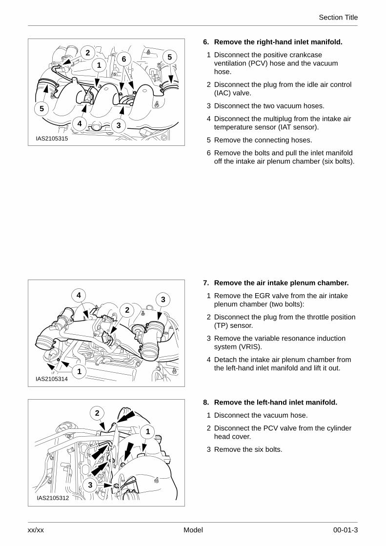
6. Remove the right-hand inlet manifold.
1 Disconnect the positive crankcaseventilation (PCV) hose and the vacuumhose.
2 Disconnect the plug from the idle air control(IAC) valve.
3 Disconnect the two vacuum hoses.
4 Disconnect the multiplug from the intake airtemperature sensor (IAT sensor).
5 Remove the connecting hoses.
6 Remove the bolts and pull the inlet manifoldoff the intake air plenum chamber (six bolts).
IAS21053141
32
4
7. Remove the air intake plenum chamber.
1 Remove the EGR valve from the air intakeplenum chamber (two bolts):
2 Disconnect the plug from the throttle position(TP) sensor.
3 Remove the variable resonance inductionsystem (VRIS).
4 Detach the intake air plenum chamber fromthe left-hand inlet manifold and lift it out.
IAS2105312
1
2
3
8. Remove the left-hand inlet manifold.
1 Disconnect the vacuum hose.
2 Disconnect the PCV valve from the cylinderhead cover.
3 Remove the six bolts.

Section Title
xx/xx Model 00-01-4
ELD2105163
9. Detach the PCV bracket.
ELD2105164
10. Remove the fuel rails.
Disconnect the six fuel injection plugs.
ELD2105167
11. Disconnect the plugs and detach thethermostat housing bracket.
� Engine coolant temperature (ECT) sensorplug.
� Temperature gauge sender unit plug.
� Thermostat housing bracket.
ELD2105165
12. Remove the coolant pipe.
Section Title
xx/xx Model 00-01-5
ELD2105166
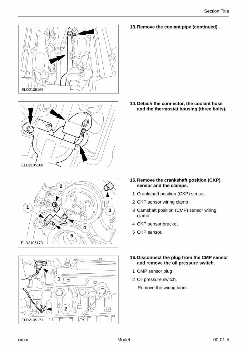
13. Remove the coolant pipe (continued).
ELD2105168
14. Detach the connector, the coolant hoseand the thermostat housing (three bolts).
ELD2105170
31
2
5
4
15. Remove the crankshaft position (CKP)sensor and the clamps.
1 Crankshaft position (CKP) sensor.
2 CKP sensor wiring clamp
3 Camshaft position (CMP) sensor wiringclamp
4 CKP sensor bracket
5 CKP sensor.
ELD2105171
1
2
16. Disconnect the plug from the CMP sensorand remove the oil pressure switch.
1 CMP sensor plug
2 Oil pressure switch.
Remove the wiring loom.

Section Title
xx/xx Model 00-01-6
PZS2105341
17. Remove the exhaust manifold heatshields (left-hand side shown).
ELD2105174
18. Remove the cylinder head heat shields(left-hand side shown).
ELD2105175
19. Pull out the dipstick tube and detach thelifting eye.
ELD2105176
20. Remove the PCV connector (left-handside shown).

Section Title
xx/xx Model 00-01-7
ELD2105180
21. Detach the two cylinder head covers(left-hand side shown).
ELD2105181
22. Set the engine to TDC.
ELD2105182
23. Remove the upper chain guide (left-handside shown).

Section Title
xx/xx Model 00-01-8
1ELD2105238
2
NOTE: The chain tensioner is locked once thereis an audible click and when it has reached itsstop.
24. Remove the right and left-hand chaintensioners.
1 Remove the chain tensioner blanking plug(4,5 mm Allen key).
NOTE: Use the TORX T30 angled socket.
� Lock the chain tensioner by rotating itclockwise.
2 Unscrew the bolts.
ELD2105184
25. Remove the chain guide bolt.
Prise out the blanking plug.
ELD2105185
NOTE: Undo the camshaft sprocket bolts tenturns.
26. Remove the camshaft sprockets.

Section Title
xx/xx Model 00-01-9
ELD2105186
NOTE: Hold the timing chain to prevent it fallingin.
27. Remove the camshaft sprockets(continued).
� Lightly tap on the drive plates to loosenthem from the camshaft sprockets.
� Remove the camshaft sprocket bolts.
� Remove the camshaft sprockets, driveplates and thrust washers and lay themaside in order.
ELD2105187
NOTE: Loosening sequence: workingdiagonally from the outside inwards.
NOTE: Remove the camshaft bearing caps andthe camshafts and lay them aside in order.
28. Remove the camshaft bearing caps andtake out the camshafts.
ELD2105189
2 7 35
4681
8 164
3 5 27
NOTE: Bolt-slackening sequence.
29. Remove the cylinder heads.
� Remove the cylinder head bolts withspecial tool 21–002.
� Remove the bolt from the timing chainhousing.
� Remove the cylinder heads and thecylinder head gaskets.

Section Title
xx/xx Model 00-01-10
ELD2105190
30. Detach the coolant pump pulley.
Use a universal strap wrench to stop thecoolant pump pulley from turning.
31. Detach the coolant hose.
ELD210519121–147
32. Remove the crankshaft vibration damper.
� Immobilise the flywheel with locking tool21–135.
� Unscrew the bolt approximately 20 mm.
� Pull off the crankshaft vibration damper.
� Remove the bolt.
� Remove the immobilising tool.
ELD2105192
33. Detach the coolant pump.
12
ELD2105193
3
34. Remove the oil filter connector.
1 Oil filter
2 Oil cooler
3 Oil filter connector

Section Title
xx/xx Model 00-01-11
1
12
13
14
151665
24
22
21
2
20
19
18
4 3 7
8
9
10
11
17
23
ELD2105194
NOTE: Bolt-slackening sequence.
NOTE: Remove the sump downwards so thatabraded particles and sludge cannot fall intothe engine.
35. Remove the sump.
3
1 2
ELD2105195
NOTE: The left-hand chain guide attached tothe timing chain housing.
36. Detach the timing chain housing (eightbolts).
1 Seven bolts at the front, one at the top of theback.
2 Remove the crankshaft oil seal withremover 21–051.
3 Lift the left-hand timing chain away from thechain guides and remove the timing chainhousing.
Section Title
xx/xx Model 00-01-12
ELD2105196
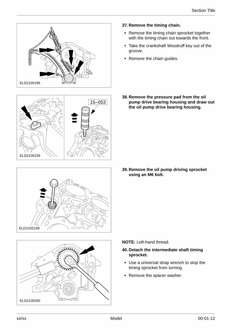
37. Remove the timing chain.
� Remove the timing chain sprocket togetherwith the timing chain out towards the front.
� Take the crankshaft Woodruff key out of thegroove.
� Remove the chain guides.
15–053
ELD2105239
38. Remove the pressure pad from the oilpump drive bearing housing and draw outthe oil pump drive bearing housing.
ELD2105199
39. Remove the oil pump driving sprocketusing an M6 bolt.
ELD2105200
NOTE: Left-hand thread.
40. Detach the intermediate shaft timingsprocket.
� Use a universal strap wrench to stop thetiming sprocket from turning.
� Remove the spacer washer.

Section Title
xx/xx Model 00-01-13
ELD2105201
41. Remove the bearing plate and withdrawthe intermediate shaft.
ELD2105202
42. Detach the oil baffle plate and the oilpump.
ELD2105215
43. Withdraw the driving shaft from the oilpump.
4
4
5
5
ELD2105203
�CAUTION: Do not damage the cylinderbores.
44. Remove the pistons.
� Remove the carbon from the upper edge ofthe cylinder bores.
� Detach the big-end bearing caps.
� Remove the pistons and connecting rods.

Section Title
xx/xx Model 00-01-14
4 3 2
ELD2105204
45. Remove the crankshaft.
Detach the main bearing caps.
ELD2105205
46. Take out the crankshaft.
Remove the radial oil seal.
Assemble
47. Preparatory measures.
All mating faces and reusable parts shouldbe thoroughly cleaned and checked fordamage.
Section Title
xx/xx Model 00-01-15
10mm
10mm
A
XY
B
D2105206
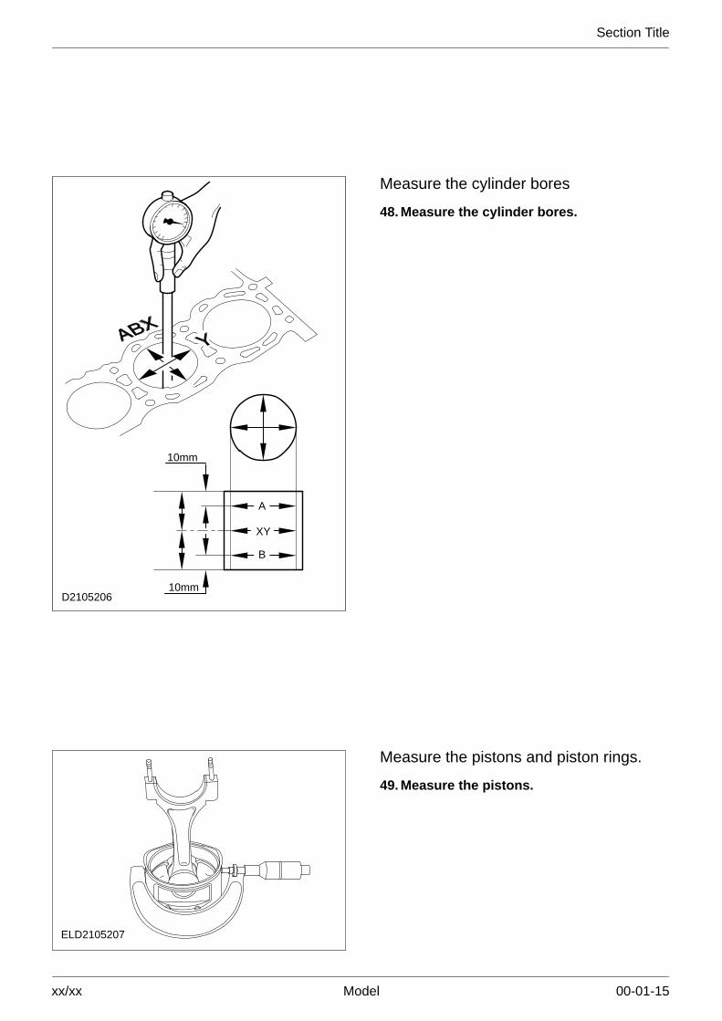
Measure the cylinder bores
48. Measure the cylinder bores.
ELD2105207
Measure the pistons and piston rings.
49. Measure the pistons.

Section Title
xx/xx Model 00-01-16
ELD2105208
�CAUTION: Do not mix up the piston rings.They should be refitted in the samepositions.
NOTE: Carry out the measurement at the topend of the run-in cylinder bore.
50. Measure the piston ring gaps.
� If necessary renew the piston rings.
� See technical data for piston ring gaps.

Section Title
xx/xx Model 00-01-17
M2103771
NOTE: Measure the clearance with the ringprotruding from the groove.
51. Measure the piston ring clearance.
ELD2105214
52. Measure the diameter of the main andbig-end bearing journals.
� In each case, repeat the measurement 90°around the circumference.
� Rework or renew the crankshaft ifnecessary.
Measure the main bearing clearance.
53. General notes.
NOTE: Measure each bearing individually witha length of Plastigage thread.
� Fit the main bearing cap of the bearingwhich is to be measured and tighten it tothe specified torque.
� The bearing shells/journals and thecrankshaft must be clean and free of oil.
� The measuring point should be near therespective dead centre position.
� The crankshaft must not be turned duringthe measuring operation.
� Measure the bearing clearances one afterthe other in numerical order.

Section Title
xx/xx Model 00-01-18
D2105209
54. Measure the crankshaft main bearingclearance.
Lay a length of Plastigage thread on thebearing journal across the bearing.
97 Nm
4 2 1
D2105210
3
NOTE: The main bearing cap numbering startsat the timing chain end, to which the arrows alsopoint.
� Fit the main bearing caps with theassociated bearing shells and tighten them.
� Remove the main bearing caps.
D2105211
55. Compare the Plastigage thread with thePlastigage scale.
If the reading does not correspond to thespecified bearing clearance, renew thebearing shells as necessary and repeat theoperation from step 54.

Section Title
xx/xx Model 00-01-19
97 Nm
4 2 1
D2105210
3
NOTE: Installation position of the studs.
NOTE: The main bearing cap numbering startsat the timing chain end, to which the arrows alsopoint.
56. Install the crankshaft.
� Coat the crankshaft main bearing journals,bearing shells, and all bolt threads and boltcontact faces with engine oil.
� Fit the crankshaft.
� Fit the rear main bearing cap using sealer(ESK-M4G269).
� Fit the main bearing caps with theassociated bearing shells.
� Tighten the bolts.
ELD2105212
57. Check the crankshaft end float.
� Set up a dial indicator.
� Check the end float by lifting the crankshaft.
58. If necessary, correct the end float withthrust half rings on main bearing no. 3.

Section Title
xx/xx Model 00-01-20
ELD2105213
NOTE: The numbering on the connecting rodsstarts at the timing chain end. The arrow on thepiston crown points towards the timing chainend.
59. Fit the pistons.
� Lubricate the pistons and cylinder bores withengine oil.
� Arrange the piston ring gaps at 120�intervals.
� Compress the piston rings with a proprietarypiston ring compressor.
� Fit the associated bearing shells clean andoiled into the connecting rods and thebig-end bearing caps.
� Press the pistons into the cylinders using thehandle of a hammer, guiding the connectingrods on to the big-end bearing journals. Theappropriate big-end bearing journal must beat BDC.
1 2
ELZ9621176
21,8
6AA
54,3 0,539,35 1,25
KX 110
54,3 0,5
KX 900
5AB
30,75 0,25
7,5
23,3
9
15 19

Section Title
xx/xx Model 00-01-21
60. Identifying used conrod bolts andconnecting rods.
4
4
5
5
30 Nm
ELD2105703
Measure the big-end bearing clearance.
Only for engines with conrods and conrod bolts6AA or KX110.
61. Measure the big-end bearing clearance.
Carry out the same procedure as formeasuring the main bearing clearance.
NOTE: The connecting rods and their bearingcaps have the same numbers.
62. Fit the big-end bearing caps.
� Lubricate the bearing shells, big-end bearingjournals and the bolt threads and boltcontact faces with engine oil.
� Fit the associated big-end bearing caps withthe bearing shells and secure them.
Section Title
xx/xx Model 00-01-22
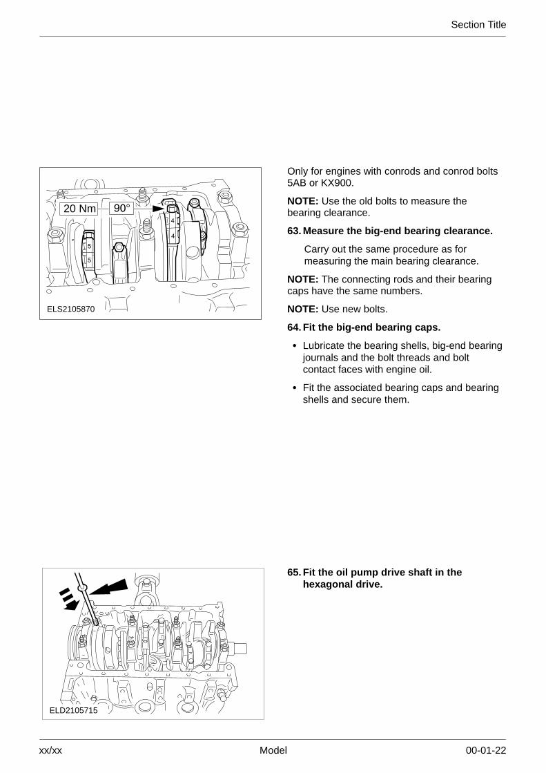
ELS2105870
20 Nm
Only for engines with conrods and conrod bolts5AB or KX900.
NOTE: Use the old bolts to measure thebearing clearance.
63. Measure the big-end bearing clearance.
Carry out the same procedure as formeasuring the main bearing clearance.
NOTE: The connecting rods and their bearingcaps have the same numbers.
NOTE: Use new bolts.
64. Fit the big-end bearing caps.
� Lubricate the bearing shells, big-end bearingjournals and the bolt threads and boltcontact faces with engine oil.
� Fit the associated bearing caps and bearingshells and secure them.
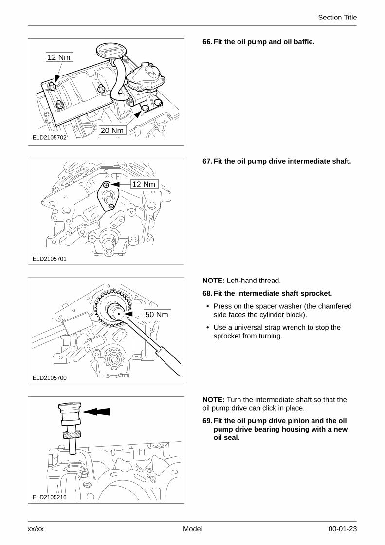
ELD2105715
65. Fit the oil pump drive shaft in thehexagonal drive.
Section Title
xx/xx Model 00-01-23
20 NmELD2105702
12 Nm
66. Fit the oil pump and oil baffle.
12 Nm
ELD2105701
67. Fit the oil pump drive intermediate shaft.
50 Nm
ELD2105700
NOTE: Left-hand thread.
68. Fit the intermediate shaft sprocket.
� Press on the spacer washer (the chamferedside faces the cylinder block).
� Use a universal strap wrench to stop thesprocket from turning.
ELD2105216
NOTE: Turn the intermediate shaft so that theoil pump drive can click in place.
69. Fit the oil pump drive pinion and the oilpump drive bearing housing with a newoil seal.
Section Title
xx/xx Model 00-01-24
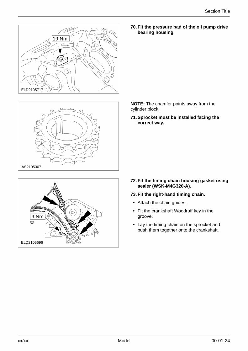
19 Nm
ELD2105717
70. Fit the pressure pad of the oil pump drivebearing housing.
IAS2105307
NOTE: The chamfer points away from thecylinder block.
71. Sprocket must be installed facing thecorrect way.
ELD2105696
9 Nm
72. Fit the timing chain housing gasket usingsealer (WSK-M4G320-A).
73. Fit the right-hand timing chain.
� Attach the chain guides.
� Fit the crankshaft Woodruff key in thegroove.
� Lay the timing chain on the sprocket andpush them together onto the crankshaft.

Section Title
xx/xx Model 00-01-25
19 Nm
21–137
ELD2105695
NOTE: The left-hand chain guides are attachedto the timing chain housing.
74. Fit the timing chain housing.
� Lay the left-hand timing chain on thesprocket and fit the timing chain housing.
� Align the timing chain housing using thespecial tool.
� Screw in the timing chain housing boltsfinger tight.
� Hold the chain tight.
� Check that the special tool is accessible.
NOTE: Ensure that the timing chain housingand cylinder block mating faces are flush.
� Tighten the eight bolts on the timing chainhousing (one on the back at the top).
� Remove the special tool.
ELD21052183
1
2
21–137
75. Install the crankshaft front oil seal.
1 Special tool
2 Spacer sleeve
3 Bolt on the crankshaft vibration damper.
ELD2105219
76. Fit the sump gaskets.
Coat the ends of the new gaskets withsealer (ESK-M4G269).

Section Title
xx/xx Model 00-01-26
1
12
13
14
151665
24
22
21
2
20
19
18
4 3 7
8
9
10
11
17
23
12 Nm
ELD2105694
NOTE: Tightening sequence and different boltlengths.
77. Fit the sump.
� Bolts five and six: M6 x 115
� Bolts 23 and 24: M6 x 45
� All other bolts: M6 x 20
ELD2105693
1
12 Nm2 3
78. Fit the oil filter connector.
1 Oil filter connector with a new seal.
2 Oil cooler
3 New oil filter.
12 Nm
ELD2105692
79. Fit the coolant pump with a new gasket.

Section Title
xx/xx Model 00-01-27
ELD2105690
19 Nm
80. Fit the coolant pump pulley.
Use a universal strap wrench to stop thepulley from turning.
81. Fit the coolant hose.
ELD2105691
45 Nm 90°
NOTE: The stepped side of the disc faces thecylinder block.
82. Fit the crankshaft vibration damper.
� Immobilise the flywheel with locking tool21–135.
� Fit a new O-ring.
� Remove the immobilising tool.
21–059 C
ELD2105220
83. Fit the crankshaft rear oil seal.
� Insert a new oil seal into the special tool.
� Fit the oil seal.
ELD2105222
FRONT TOPNOTE: FRONT TOP marking.
84. Fit the cylinder head gaskets.
Cut through the left-hand cylinder headgasket, remove the corners and smooth offany sharp edges.

Section Title
xx/xx Model 00-01-28
ELD2105230
21–128
85. Insert the studs into the cylinder block.
ELD2105223
86. Fit the cylinder heads (left-hand sideshown.
� Fit the cylinder heads.
� Guide the timing chains through the timingchain housing and secure them to preventthem from falling in.
7 2 4 6
5 3 1 8
8 1 3 5
6 4 2 7
ELD2105689
19 Nm
19 Nm
NOTE: The cylinder head bolts may only bereused twice. Mark them with a punch mark onthe bolt head when they are reused.
87. Fit the left-hand cylinder head(continued).
� Insert the cylinder head bolts and tightenthem to the first stage in the indicatedsequence.
� Screw in the timing chain housing bolt.

Section Title
xx/xx Model 00-01-29
50 Nm
21–540
ELD2105232
21–002
180°
NOTE: Tightening sequence (seesub-operation 87.).
88. Tighten the cylinder head bolts.
ELD2105231
89. Set the crankshaft to the TDC marking forcylinder no. 1.
IAS2105274
E
F
G
H
5
6
7
8
A
B
C
D
1
2
3
4

Section Title
xx/xx Model 00-01-30
NOTE: The wider contact areas of camshaftbearing caps 1 and 5 and A and E pointtowards the middle.
90. Identification of the camshaft baringcaps.
B D
GFE
CA
H
ELD2105226
10 Nm91. Fit the hydraulic tappets.
NOTE: Tightening sequence: evenly, workingdiagonally from the inside outwards.
92. Install the camshafts for the right-handcylinder head.
� The inlet cams on camshaft 1 must bevertical at cylinder no. 1.
� The exhaust cams on camshaft 2 must bevertical at cylinder no. 1.
� Fit the camshaft bearing caps.
93. Install the camshafts for the left-handcylinder head.
� The inlet cams on camshaft 3 must bevertical at cylinder no. 6.
� The exhaust cams on camshaft 4 must bevertical at cylinder no. 4.
� Fit the camshaft bearing caps.
IAS2105275
NOTE: The drive plate follower must engage inthe bore on the camshaft sprocket.
94. Camshaft components.

Section Title
xx/xx Model 00-01-31
IAS2105278
95. Set the camshafts to the timing marks.
� Push on the thrust washers and drive plates,screw in the bolts a few turns.
� Set the camshafts to the timing marks.
� Remove the drive plates.
3 4
72 Nm
ELD2105228
NOTE: Engine is set to TDC.
NOTE: Do not rotate the camshafts.
96. Attach the camshaft sprockets.
� Pull the timing chain tight on the driving run(the opposite side to the chain tensioner),and working from this side attach thecamshaft sprockets (do not yet tighten thebolts).
ELD2105738
9 Nm
2
1
13 Nm
NOTE: The left and right-hand chain tensionersare different (thin left-hand inner spacer andthick right-hand inner spacer). The chaintensioner must be locked before installation.
97. Fit the right and left-hand chaintensioners
1 Screw in the bolts.
Tension the timing chain according tostep 98.
2 Screw in chain tensioner blanking plugs(4,5 mm).
IAS2105270
NOTE: The chain tensioner is released oncethere is an audible click and when it hasreached its stop.
98. Tighten the timing chains.
NOTE: Use the TORX T30 angled socket.
Twist the chain tensioner anti-clockwise torelease it.
Section Title
xx/xx Model 00-01-32
ELD2105233
99. Carefully turn the engine through tworotations and check the valve timings.
If necessary, follow steps 53. to 56. tocorrect the valve timings.
19 Nm
ELD2105682
100.Fit the upper chain guides.
9 Nm
ELD2105684
101.Fit the right-hand chain guide bolt.
� Screw in the chain guide bolt.
� Fit the blanking plug in the bore using a newO-ring.
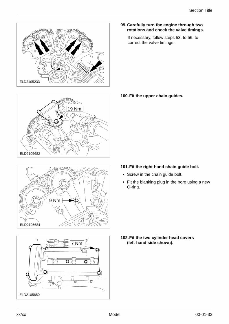
ELD2105680
7 Nm102.Fit the two cylinder head covers
(left-hand side shown).

Section Title
xx/xx Model 00-01-33
9 Nm
ELD21056769 Nm
103.Fit the PCV connector (left-hand sideshown).
9 Nm
19 Nm
ELD2105675
104.Fit the oil dipstick tube and enginelifting eye.
Insert the oil dipstick.
9 Nm
ELD2105674
105.Fit the cylinder head heat shields(left-hand side shown).
PZS2105841
9 Nm
106.Fit the exhaust manifold heat shields(left-hand side shown).

Section Title
xx/xx Model 00-01-34
ELD2105171
1
2
107.Connect the CMP sensor multiplug andfit the oil pressure switch.
Route the wiring loom.
1 Camshaft position (CMP) sensor.
2 Oil pressure switch.
Connect the oil pressure switch multiplug.
5
9Nm 1
3
2
9 Nm
9 Nm
9 Nm
4
ELD2105670
108.Fit the CKP sensor and the clips.
1 CKP sensor.
2 CKP sensor wiring clip.
3 Bracket for CKP sensor.
4 CMP sensor wiring clip.
5 CKP sensor plug.
ELD2105668
9 Nm109.Fit the thermostat housing.
� Guide in the thermostat housing and attachthe coolant hose.
� Fit the three thermostat housing bolts.
� Fit the connector.
9 Nm
ELD2105666
110. Fit the coolant pipe.

Section Title
xx/xx Model 00-01-35
19 Nm
ELD2105665
111. Fit the coolant pipe (continued)
9 Nm
ELD2105667
112. Connect the plugs and fit the thermostathousing bracket.
� Engine coolant temperature (ECT) sensorplug.
� Temperature gauge sender unit plug.
� Thermostat housing bracket.
9 NmELD2105664
113. Fit the fuel rails.
Connect the six fuel injection valvemultiplugs.
IAS2105812
3
2
16 Nm1
114. Fit the left-hand inlet manifold with anew gasket.
1 Fit the six bolts.
2 Insert the PCV valve into the cylinder headcover.
3 Connect the vacuum hose.
Move the wiring and hoses for the inlet airplenum chamber and the right-hand inletmanifold into installation position.

Section Title
xx/xx Model 00-01-36
IAS21058149 Nm 4
32
1
115. Fit the air intake plenum chamber.
1 Push the air intake plenum chamber ontothe left-hand inlet manifold.
2 Attach the VRIS.
3 Connect the TP sensor plug.
4 Attach the EGR valve to the inlet manifold(two bolts).
5
2
3
2
4
6 16 Nm 1
IAS2105815
116. Attach the right-hand inlet manifold witha new gasket.
1 Push the inlet manifold onto the air intakeplenum chamber and fit the six bolts.
2 Fit the connecting hoses.
3 Connect the IAT sensor multiplug.
4 Push on the two vacuum hoses.
5 Connect the IAC valve multiplug.
6 Push on the PCV hose and the vacuumhose.
9 Nm
ELD2105663
117. Fit the bracket for the PCV hose.
Section Title
xx/xx Model 00-01-37
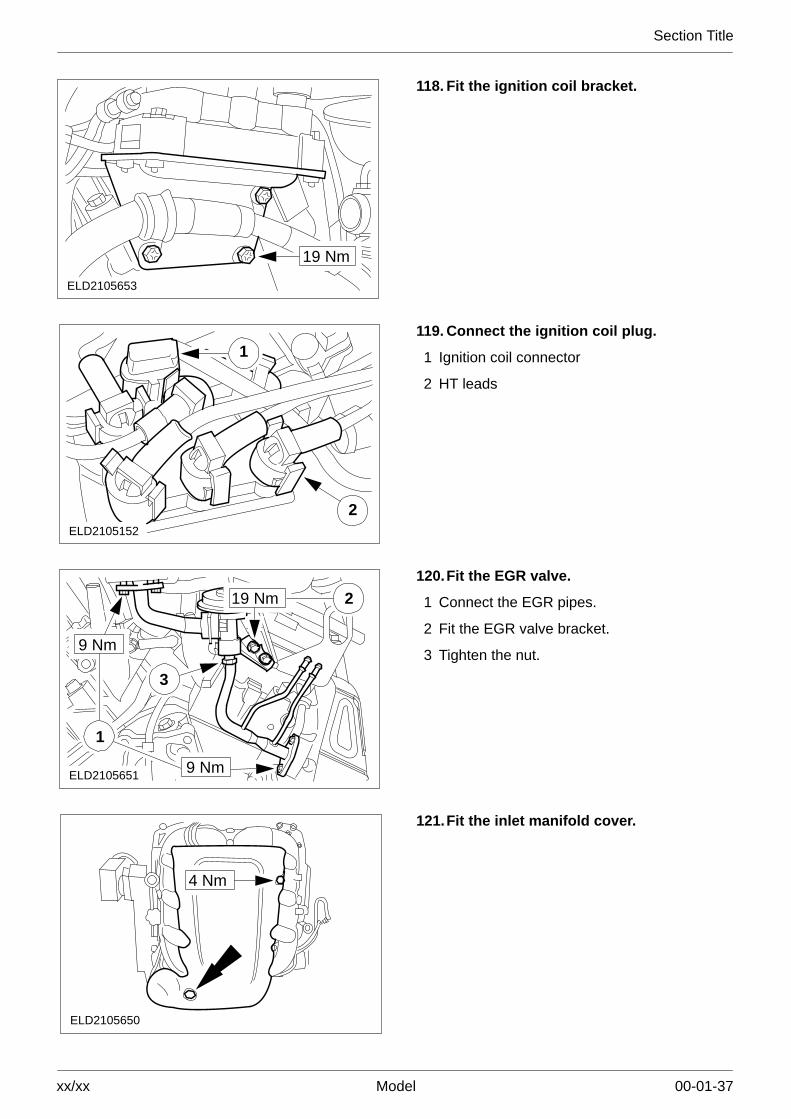
19 Nm
ELD2105653
118. Fit the ignition coil bracket.
1
2ELD2105152
119. Connect the ignition coil plug.
1 Ignition coil connector
2 HT leads
3
2
1
9 Nm
9 Nm
19 Nm
ELD2105651
120.Fit the EGR valve.
1 Connect the EGR pipes.
2 Fit the EGR valve bracket.
3 Tighten the nut.
ELD2105650
4 Nm
121.Fit the inlet manifold cover.

Section Title
xx/xx Model 00-01-38
ELD2105235
21–064
122.Detach the engine from the assemblystand.