engine management systems - ron beckett's home...
TRANSCRIPT

GENERIC ENGINE MANAGEMENT SYSTEM (GEMS)
GENERIC ENGINE MANAGEMENT SYSTEM (GEMS)Land Rover moves into the next level of sophistication in engine management with the Generic Engine Management System (GEMS). GEMS incorporates the function of the distributor into the ECM to provide a computer-controlled Distributorless Ignition System (DIS).
GEMS also provides more precise fuel delivery through the use of adaptive operating software and Sequential Multiport Fuel Injection. More sophisticated OBD II diagnostic capabilities are also included as part of the package.
New default strategies have been incorporated into the GEMS to allow the vehicle to continue running in the event of sensor failure - sometimes without any apparent symptoms other than an illuminated MIL. When this is occurring, however, there is a reduction in vehicle performance, economy, or emissions system operation.
Generic Engine Management System (GEMS) 107

GENERIC ENGINE MANAGEMENT SYSTEM (GEMS)
ELECTRONIC CONTROL MODULE (ECM)
GEMS Electronic Control Module
System InputsThe ECM is mounted in the engine compartment. The expanded list of ECM inputs is as follows:
• Crankshaft Position (CKP) Sensor• Ignition Signal (Key on signal)• Camshaft Position (CMP) Sensor • Knock Sensor (KS)• Intake Air Temperature Sensor• Engine Coolant Temperature (ECT) Sensor• Engine Fuel Temperature (EFT) Sensor• Throttle Position Sensor (TPS)• Mass Air Flow Sensor (MAFS)• Park/Neutral Position Switch (PNPS)• Heated Oxygen Sensors (4)• Fuel Level Sensor• Heated Front Screen• Road speed (Range Rover)• Air Conditioning request• Battery Voltage• Cooling fan request• Security link• ABS link
Several of these inputs (road speed, A/C request) originate in the ABS Module and are received via the Body Control Module.
108

GENERIC ENGINE MANAGEMENT SYSTEM (GEMS)
System OutputsSystem outputs are as follows:
• A/C Compressor Clutch • Fan Control• Fuel Injectors• Idle Air Control• Purge Valve• Malfunction Indicator Lamp (MIL)• Fuel Pump Relay• Main Relay• Coil Driver
NEW COMPONENTSMany system inputs and outputs remain similar previous models. There are, however, several important exceptions:
Generic Engine Management System (GEMS) 109
GENERIC ENGINE MANAGEMENT SYSTEM (GEMS)
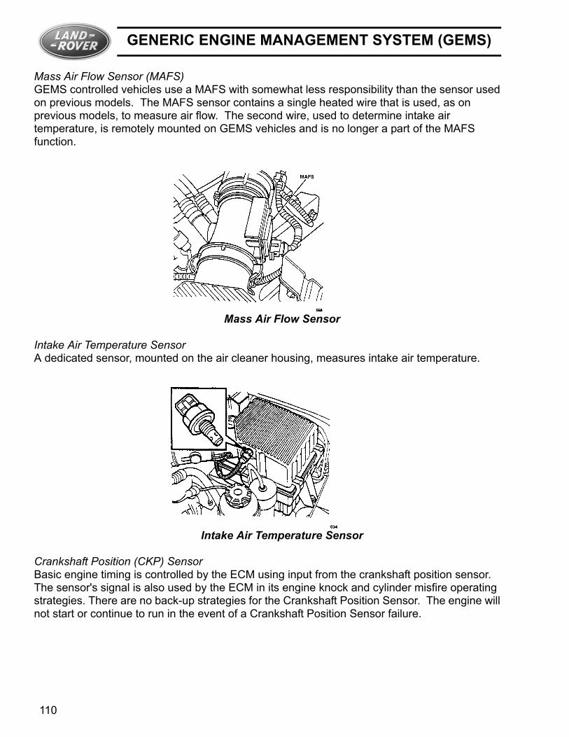
Mass Air Flow Sensor (MAFS)GEMS controlled vehicles use a MAFS with somewhat less responsibility than the sensor used on previous models. The MAFS sensor contains a single heated wire that is used, as on previous models, to measure air flow. The second wire, used to determine intake air temperature, is remotely mounted on GEMS vehicles and is no longer a part of the MAFS function.
Mass Air Flow Sensor
Intake Air Temperature SensorA dedicated sensor, mounted on the air cleaner housing, measures intake air temperature.
Intake Air Temperature Sensor
Crankshaft Position (CKP) SensorBasic engine timing is controlled by the ECM using input from the crankshaft position sensor. The sensor's signal is also used by the ECM in its engine knock and cylinder misfire operating strategies. There are no back-up strategies for the Crankshaft Position Sensor. The engine will not start or continue to run in the event of a Crankshaft Position Sensor failure.
110

GENERIC ENGINE MANAGEMENT SYSTEM (GEMS)
The sensor is mounted on the flywheel housing.
Crankshaft Position Sensor
A detailed description of the Crankshaft Position Sensor's signal is provided in the Ignition System section of this book.
Crankshaft Position Sensor Scope Pattern
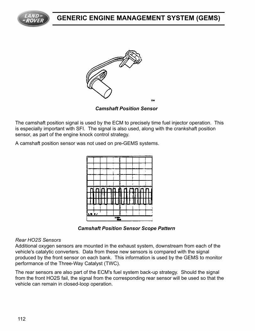
Camshaft Position (CMP) SensorCamshaft position input is provided to the GEMS by a Hall Effect sensor located on the engine's front cover. Electronic pulses are produced as lobes on the cam chain wheel pass the sensor tip. Four pulses are produced for every two engine revolutions.
Generic Engine Management System (GEMS) 111
GENERIC ENGINE MANAGEMENT SYSTEM (GEMS)
Camshaft Position Sensor
The camshaft position signal is used by the ECM to precisely time fuel injector operation. This is especially important with SFI. The signal is also used, along with the crankshaft position sensor, as part of the engine knock control strategy.
A camshaft position sensor was not used on pre-GEMS systems.
Camshaft Position Sensor Scope Pattern
Rear HO2S SensorsAdditional oxygen sensors are mounted in the exhaust system, downstream from each of the vehicle's catalytic converters. Data from these new sensors is compared with the signal produced by the front sensor on each bank. This information is used by the GEMS to monitor performance of the Three-Way Catalyst (TWC).
The rear sensors are also part of the ECM's fuel system back-up strategy. Should the signal from the front HO2S fail, the signal from the corresponding rear sensor will be used so that the vehicle can remain in closed-loop operation.
112

GENERIC ENGINE MANAGEMENT SYSTEM (GEMS)
Oxygen Sensor Circuit
Inertia SwitchThe inertia switch on GEMS equipped vehicles has been relocated to the passenger compartment, behind a trim panel on the right side footwell. Operation is identical to that of previous models.
Inertia Switch
Ignition Coils
New ignition coils are used as part of the GEMS controlled Distributorless Ignition System (DIS). Four double-ended coils are mounted on a bracket at the rear of the engine compartment.
The circuit for each coil is completed by switching within the ECM. This produces sparks in two cylinders simultaneously, one cylinder on the compression stroke and one on the exhaust stroke. The spark on the exhaust stroke is the "wasted" spark described in the Ignition section of this book.
Generic Engine Management System (GEMS) 113

GENERIC ENGINE MANAGEMENT SYSTEM (GEMS)
The ECM provides precise coil operation and ignition timing based on inputs including cam and crank position, coolant temperature, engine knock and load.
Range Rover SE Ignition Coils
RelaysThe GEMS engine management system uses four relays:
• Main Relay• Ignition Relay• Starter Motor Relay• Fuel Pump Relay
Each of these relays is located in a fuse box mounted in the engine compartment.
The main relay supplies power to the ECM, fuel injectors, mass air flow meter and purge valve. Failure of this relay will prevent the engine from starting.
The ignition relay supplies power to the coils, fuel pump relay and heated oxygen sensors. This relay is immediately de-energized when the ignition key is turned to the OFF position.
The starter relay provides the power feed to the starter motor. Operation of this relay is controlled by the ignition key.
114

GENERIC ENGINE MANAGEMENT SYSTEM (GEMS)
The fuel pump relay is powered through the ignition relay and controlled by the ECM. The relay is first activated briefly with the key in the ON position to prime the fuel system. The relay remains activated during cranking and while the engine is running.
Relay Location in Fuse Box
Generic Engine Management System (GEMS) 115

GENERIC ENGINE MANAGEMENT SYSTEM (GEMS)
116
GEMS CONNECTOR PINOUTS
GEMS CONNECTOR PINOUTS
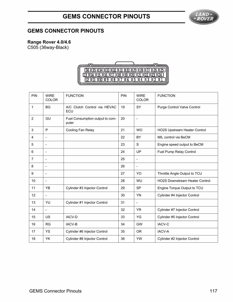
Range Rover 4.0/4.6C505 (36way-Black)
PIN WIRECOLOR
FUNCTION PIN WIRECOLOR
FUNCTION
1 BG A/C Clutch Control via HEVACECU
19 SY Purge Control Valve Control
2 GU Fuel Consumption output to com-puter
20 -
3 P Cooling Fan Relay 21 WO HO2S Upstream Heater Control
4 - 22 BY MIL control via BeCM
5 - 23 S Engine speed output to BeCM
6 - 24 UP Fuel Pump Relay Control
7 - 25 -
8 - 26 -
9 - 27 YO Throttle Angle Output to TCU
10 - 28 WU HO2S Downstream Heater Control
11 YB Cylinder #3 Injector Control 29 SP Engine Torque Output to TCU
12 - 30 YN Cylinder #4 Injector Control
13 YU Cylinder #1 Injector Control 31 -
14 - 32 YR Cylinder #7 Injector Control
15 US IACV-D 33 YG Cylinder #5 Injector Control
16 RG IACV-B 34 GW IACV-C
17 YS Cylinder #6 Injector Control 35 OR IACV-A
18 YK Cylinder #8 Injector Control 36 YW Cylinder #2 Injector Control
GEMS Connector Pinouts 117
GEMS CONNECTOR PINOUTS
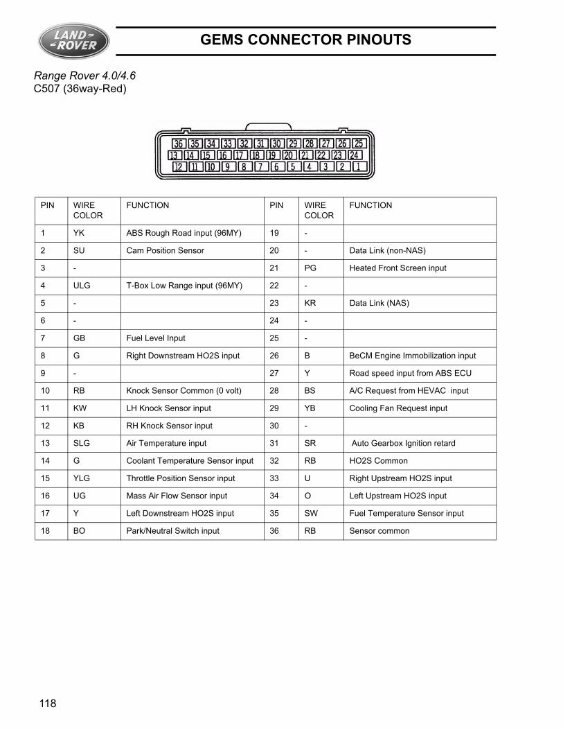
Range Rover 4.0/4.6C507 (36way-Red)
PIN WIRECOLOR
FUNCTION PIN WIRECOLOR
FUNCTION
1 YK ABS Rough Road input (96MY) 19 -
2 SU Cam Position Sensor 20 - Data Link (non-NAS)
3 - 21 PG Heated Front Screen input
4 ULG T-Box Low Range input (96MY) 22 -
5 - 23 KR Data Link (NAS)
6 - 24 -
7 GB Fuel Level Input 25 -
8 G Right Downstream HO2S input 26 B BeCM Engine Immobilization input
9 - 27 Y Road speed input from ABS ECU
10 RB Knock Sensor Common (0 volt) 28 BS A/C Request from HEVAC input
11 KW LH Knock Sensor input 29 YB Cooling Fan Request input
12 KB RH Knock Sensor input 30 -
13 SLG Air Temperature input 31 SR Auto Gearbox Ignition retard
14 G Coolant Temperature Sensor input 32 RB HO2S Common
15 YLG Throttle Position Sensor input 33 U Right Upstream HO2S input
16 UG Mass Air Flow Sensor input 34 O Left Upstream HO2S input
17 Y Left Downstream HO2S input 35 SW Fuel Temperature Sensor input
18 BO Park/Neutral Switch input 36 RB Sensor common
118
GEMS CONNECTOR PINOUTS
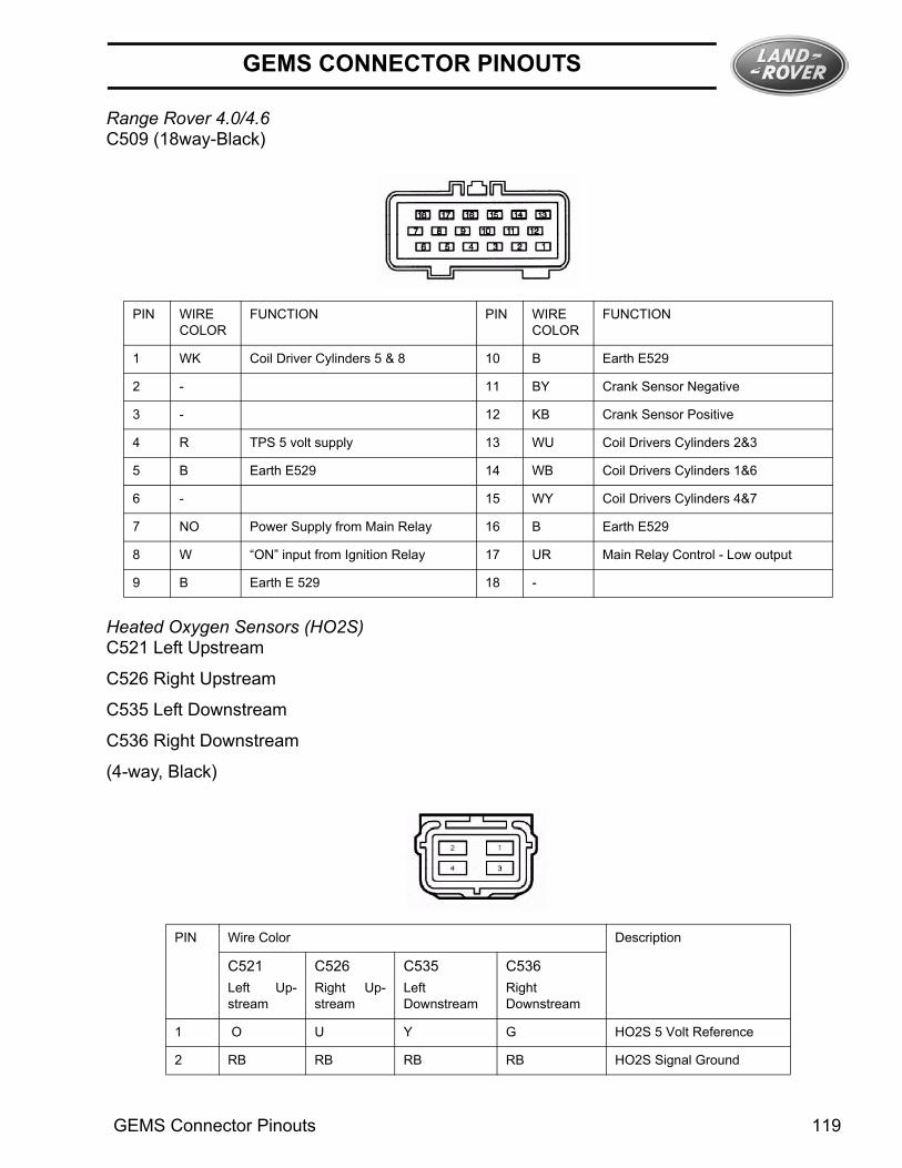
Range Rover 4.0/4.6C509 (18way-Black)
Heated Oxygen Sensors (HO2S)C521 Left Upstream
C526 Right Upstream
C535 Left Downstream
C536 Right Downstream
(4-way, Black)
PIN WIRECOLOR
FUNCTION PIN WIRECOLOR
FUNCTION
1 WK Coil Driver Cylinders 5 & 8 10 B Earth E529
2 - 11 BY Crank Sensor Negative
3 - 12 KB Crank Sensor Positive
4 R TPS 5 volt supply 13 WU Coil Drivers Cylinders 2&3
5 B Earth E529 14 WB Coil Drivers Cylinders 1&6
6 - 15 WY Coil Drivers Cylinders 4&7
7 NO Power Supply from Main Relay 16 B Earth E529
8 W “ON” input from Ignition Relay 17 UR Main Relay Control - Low output
9 B Earth E 529 18 -
PIN Wire Color Description
C521Left Up-stream
C526Right Up-stream
C535Left Downstream
C536RightDownstream
1 O U Y G HO2S 5 Volt Reference
2 RB RB RB RB HO2S Signal Ground
GEMS Connector Pinouts 119

GEMS CONNECTOR PINOUTS
Data Link Connector (X-318)C231 (16-way, Black)
3 W W W W Heater Power supply
4 WO WO WU WU Heater Control
PIN WIRECOLOR
FUNCTION PIN WIRECOLOR
FUNCTION
1 SR Air Suspension Reset 9 -
2 - 10 -
3 - 11 WLG “K”-Air Suspension
4 B Battery Negative 12 WK “L”-Air Suspension
5 BP Chassis Negative 13 YK “K”-SRS
6 - 14 YG “L”-SRS
7 KR “K”-GEMS,BeCM,HVAC,ABS 15 LGR “L”-GEMS,BeCM,HVAC,ABS
8 - 16 N Battery Positive(F33-Underhood)
120
GEMS CONNECTOR PINOUTS
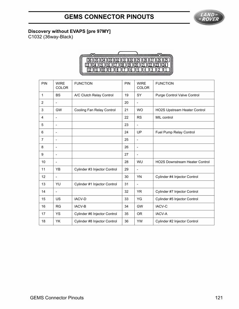
Discovery without EVAPS [pre 97MY]C1032 (36way-Black)
PIN WIRECOLOR
FUNCTION PIN WIRECOLOR
FUNCTION
1 BS A/C Clutch Relay Control 19 SY Purge Control Valve Control
2 - 20 -
3 GW Cooling Fan Relay Control 21 WO HO2S Upstream Heater Control
4 - 22 RS MIL control
5 - 23 -
6 - 24 UP Fuel Pump Relay Control
7 - 25 -
8 - 26 -
9 - 27 -
10 - 28 WU HO2S Downstream Heater Control
11 YB Cylinder #3 Injector Control 29 -
12 - 30 YN Cylinder #4 Injector Control
13 YU Cylinder #1 Injector Control 31 -
14 - 32 YR Cylinder #7 Injector Control
15 US IACV-D 33 YG Cylinder #5 Injector Control
16 RG IACV-B 34 GW IACV-C
17 YS Cylinder #6 Injector Control 35 OR IACV-A
18 YK Cylinder #8 Injector Control 36 YW Cylinder #2 Injector Control
GEMS Connector Pinouts 121

GEMS CONNECTOR PINOUTS
Discovery without EVAPS [pre-97MY]
C1017 (36way-Red)
PIN WIRECOLOR
FUNCTION PIN WIRECOLOR
FUNCTION
1 YK ABS Rough Road input (96MY) 19 -
2 SU Cam Position Sensor 20 WK Data Link (non-NAS)
3 - 21 -
4 - 22 -
5 - 23 WLG Data Link (NAS)
6 - 24 -
7 GB Fuel Level Input 25 -
8 R Right Downstream HO2S input 26 B 10AS Engine Immobilization input
9 - 27 YK Road speed input from ABS ECU
10 RB Knock Sensor Common (0 volt) 28 YB A/C Request input
11 O LH Knock Sensor input 29 PB Cooling Fan Request input
12 Y RH Knock Sensor input 30 -
13 SLG Air Temperature input 31 -
14 G Coolant Temperature Sensor in-put
32 RB HO2S Common
15 YLG Throttle Position Sensor input 33 OG Right Upstream HO2S input
16 UG Mass Air Flow Sensor input 34 GR Left Upstream HO2S input
17 GW Left Downstream HO2S input 35 SW Fuel Temperature Sensor input
18 OB Park/Neutral Switch input 36 RB Sensor common
122
GEMS CONNECTOR PINOUTS
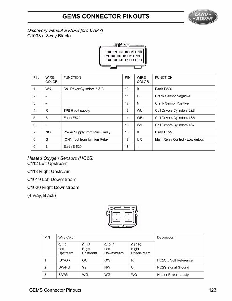
Discovery without EVAPS [pre-97MY]C1033 (18way-Black)
Heated Oxygen Sensors (HO2S)C112 Left Upstream
C113 Right Upstream
C1019 Left Downstream
C1020 Right Downstream
(4-way, Black)
PIN WIRECOLOR
FUNCTION PIN WIRECOLOR
FUNCTION
1 WK Coil Driver Cylinders 5 & 8 10 B Earth E529
2 - 11 G Crank Sensor Negative
3 - 12 N Crank Sensor Positive
4 R TPS 5 volt supply 13 WU Coil Drivers Cylinders 2&3
5 B Earth E529 14 WB Coil Drivers Cylinders 1&6
6 - 15 WY Coil Drivers Cylinders 4&7
7 NO Power Supply from Main Relay 16 B Earth E529
8 G “ON” input from Ignition Relay 17 UR Main Relay Control - Low output
9 B Earth E 529 18 -
PIN Wire Color Description
C112LeftUpstream
C113RightUpstream
C1019Left Downstream
C1020Right Downstream
1 UY/GR OG GW R HO2S 5 Volt Reference
2 UW/NU YB NW U HO2S Signal Ground
3 B/WG WG WG WG Heater Power supply
GEMS Connector Pinouts 123

GEMS CONNECTOR PINOUTS
MULTI-FUNCTION RELAY UNIT CONNECTORSDiscovery (without EVAPS) C1029 (8way-Black)
Discovery (without EVAPS) C1030 (6way-Black)
4 NU/WO WO WU WU Heater Control
PIN WIRECOLOR
FUNCTION
1 -
2 -
3 NO Load Relay power out to ECM, Injec-tors, CANPV, MAFS, CMP
4 WP Fuel Pump Power out
5 -
6 NLG Battery power to Load relay fromFuse F7
7 PW Battery power to Fuel Pump RelayFuse F6
8 NO Load Relay power out common withpin 3
PIN WIRECOLOR
FUNCTION
1 UP Fuel Pump Relay control from ECM
2 WG Key on power Fuel Pump Relay con-trol from Fuse F3
3 UR Main Relay control from ECM
4 -
5 -
6 -
124

GEMS CONNECTOR PINOUTS
Discovery with EVAPS [97-99½ MY] C1032 (36way-Black)
PIN WIRECOLOR
FUNCTION PIN WIRECOLOR
FUNCTION
1 BS A/C Clutch Relay Control 19 SY Purge Control Valve Control
2 - 20 -
3 GW Cooling Fan Relay Control 21 WO HO2S Upstream Heater Control
4 - 22 RS MIL control
5 - 23 -
6 NR Canister Vent Seal Valvecontrol
24 UP Fuel Pump Relay Control
7 - 25 -
8 - 26 -
9 - 27 -
10 - 28 WU HO2S Downstream Heater Control
11 YB Cylinder #3 Injector Control 29 -
12 - 30 YN Cylinder #4 Injector Control
13 YU Cylinder #1 Injector Control 31 -
14 - 32 YR Cylinder #7 Injector Control
15 US IACV-D 33 YG Cylinder #5 Injector Control
16 RG IACV-B 34 GW IACV-C
17 YS Cylinder #6 Injector Control 35 OR IACV-A
18 YK Cylinder #8 Injector Control 36 YW Cylinder #2 Injector Control
GEMS Connector Pinouts 125
GEMS CONNECTOR PINOUTS
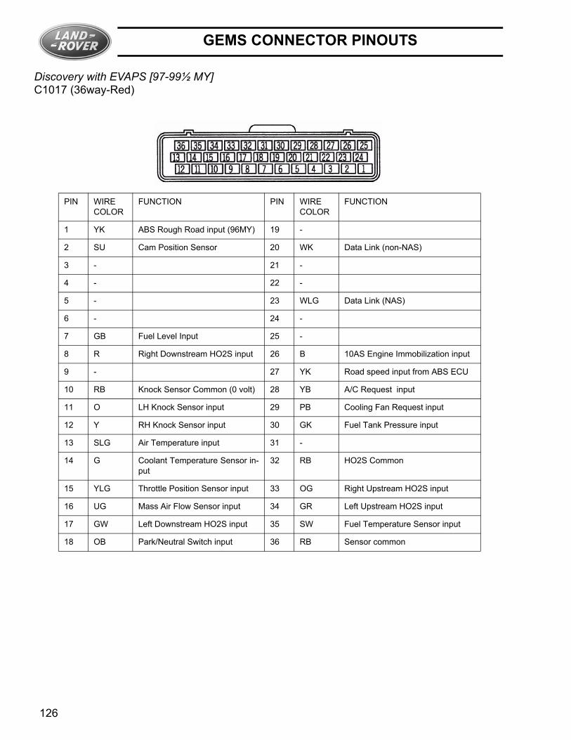
Discovery with EVAPS [97-99½ MY]C1017 (36way-Red)
PIN WIRECOLOR
FUNCTION PIN WIRECOLOR
FUNCTION
1 YK ABS Rough Road input (96MY) 19 -
2 SU Cam Position Sensor 20 WK Data Link (non-NAS)
3 - 21 -
4 - 22 -
5 - 23 WLG Data Link (NAS)
6 - 24 -
7 GB Fuel Level Input 25 -
8 R Right Downstream HO2S input 26 B 10AS Engine Immobilization input
9 - 27 YK Road speed input from ABS ECU
10 RB Knock Sensor Common (0 volt) 28 YB A/C Request input
11 O LH Knock Sensor input 29 PB Cooling Fan Request input
12 Y RH Knock Sensor input 30 GK Fuel Tank Pressure input
13 SLG Air Temperature input 31 -
14 G Coolant Temperature Sensor in-put
32 RB HO2S Common
15 YLG Throttle Position Sensor input 33 OG Right Upstream HO2S input
16 UG Mass Air Flow Sensor input 34 GR Left Upstream HO2S input
17 GW Left Downstream HO2S input 35 SW Fuel Temperature Sensor input
18 OB Park/Neutral Switch input 36 RB Sensor common
126
GEMS CONNECTOR PINOUTS
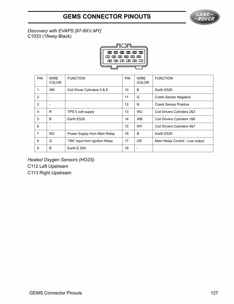
Discovery with EVAPS [97-99½ MY]C1033 (18way-Black)
Heated Oxygen Sensors (HO2S)C112 Left UpstreamC113 Right Upstream
PIN WIRECOLOR
FUNCTION PIN WIRECOLOR
FUNCTION
1 WK Coil Driver Cylinders 5 & 8 10 B Earth E529
2 - 11 G Crank Sensor Negative
3 - 12 N Crank Sensor Positive
4 R TPS 5 volt supply 13 WU Coil Drivers Cylinders 2&3
5 B Earth E529 14 WB Coil Drivers Cylinders 1&6
6 - 15 WY Coil Drivers Cylinders 4&7
7 NO Power Supply from Main Relay 16 B Earth E529
8 G “ON” input from Ignition Relay 17 UR Main Relay Control - Low output
9 B Earth E 529 18 -
GEMS Connector Pinouts 127
GEMS CONNECTOR PINOUTS
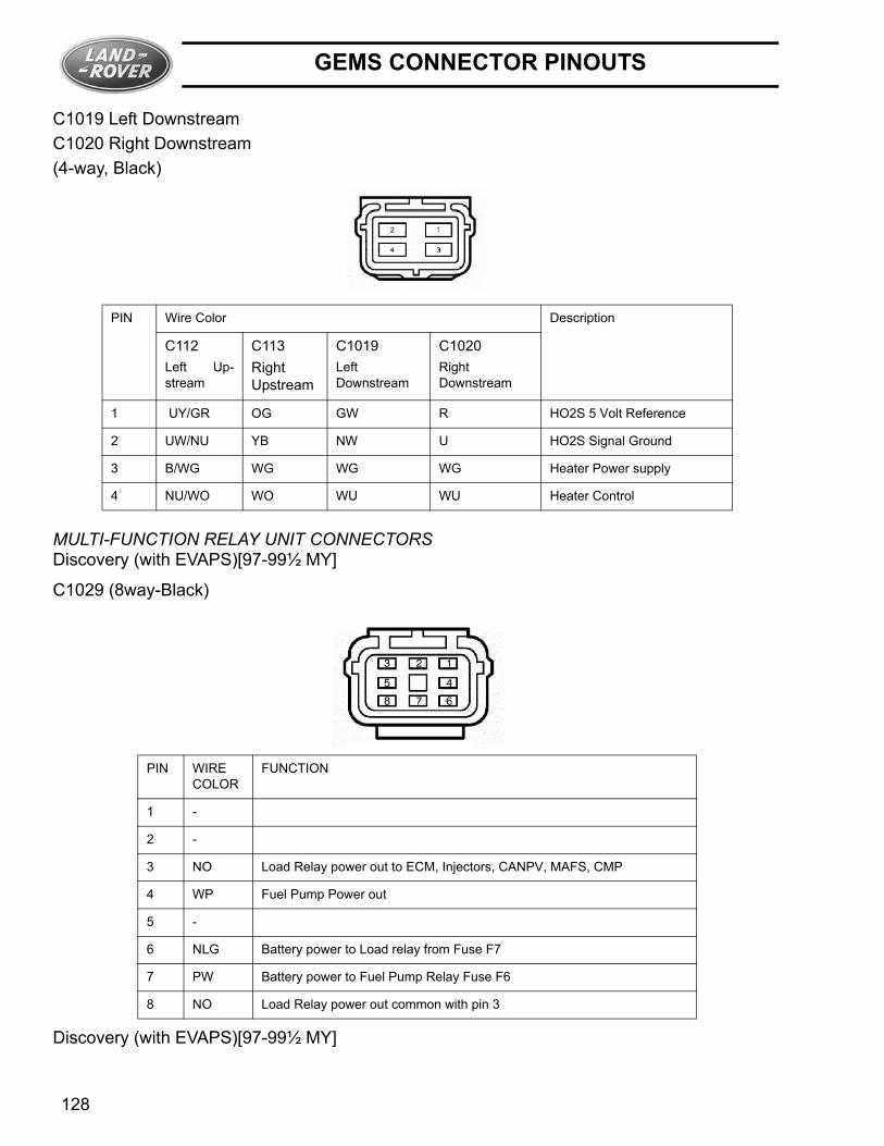
C1019 Left DownstreamC1020 Right Downstream(4-way, Black)
MULTI-FUNCTION RELAY UNIT CONNECTORSDiscovery (with EVAPS)[97-99½ MY]
C1029 (8way-Black)
Discovery (with EVAPS)[97-99½ MY]
PIN Wire Color Description
C112Left Up-stream
C113Right Upstream
C1019Left Downstream
C1020Right Downstream
1 UY/GR OG GW R HO2S 5 Volt Reference
2 UW/NU YB NW U HO2S Signal Ground
3 B/WG WG WG WG Heater Power supply
4 NU/WO WO WU WU Heater Control
PIN WIRECOLOR
FUNCTION
1 -
2 -
3 NO Load Relay power out to ECM, Injectors, CANPV, MAFS, CMP
4 WP Fuel Pump Power out
5 -
6 NLG Battery power to Load relay from Fuse F7
7 PW Battery power to Fuel Pump Relay Fuse F6
8 NO Load Relay power out common with pin 3
128
GEMS CONNECTOR PINOUTS
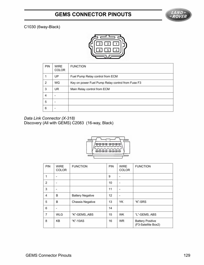
C1030 (6way-Black)
Data Link Connector (X-318)Discovery (All with GEMS) C2083 (16-way, Black)
PIN WIRECOLOR
FUNCTION
1 UP Fuel Pump Relay control from ECM
2 WG Key on power Fuel Pump Relay control from Fuse F3
3 UR Main Relay control from ECM
4 -
5 -
6 -
PIN WIRECOLOR
FUNCTION PIN WIRECOLOR
FUNCTION
1 - 9 -
2 - 10 -
3 - 11 -
4 B Battery Negative 12 -
5 B Chassis Negative 13 YK “K”-SRS
6 - 14
7 WLG “K”-GEMS,,ABS 15 WK “L”-GEMS, ABS
8 KB “K”-10AS 16 WR Battery Positive (F3-Satellite Box2)
GEMS Connector Pinouts 129

GEMS CONNECTOR PINOUTS
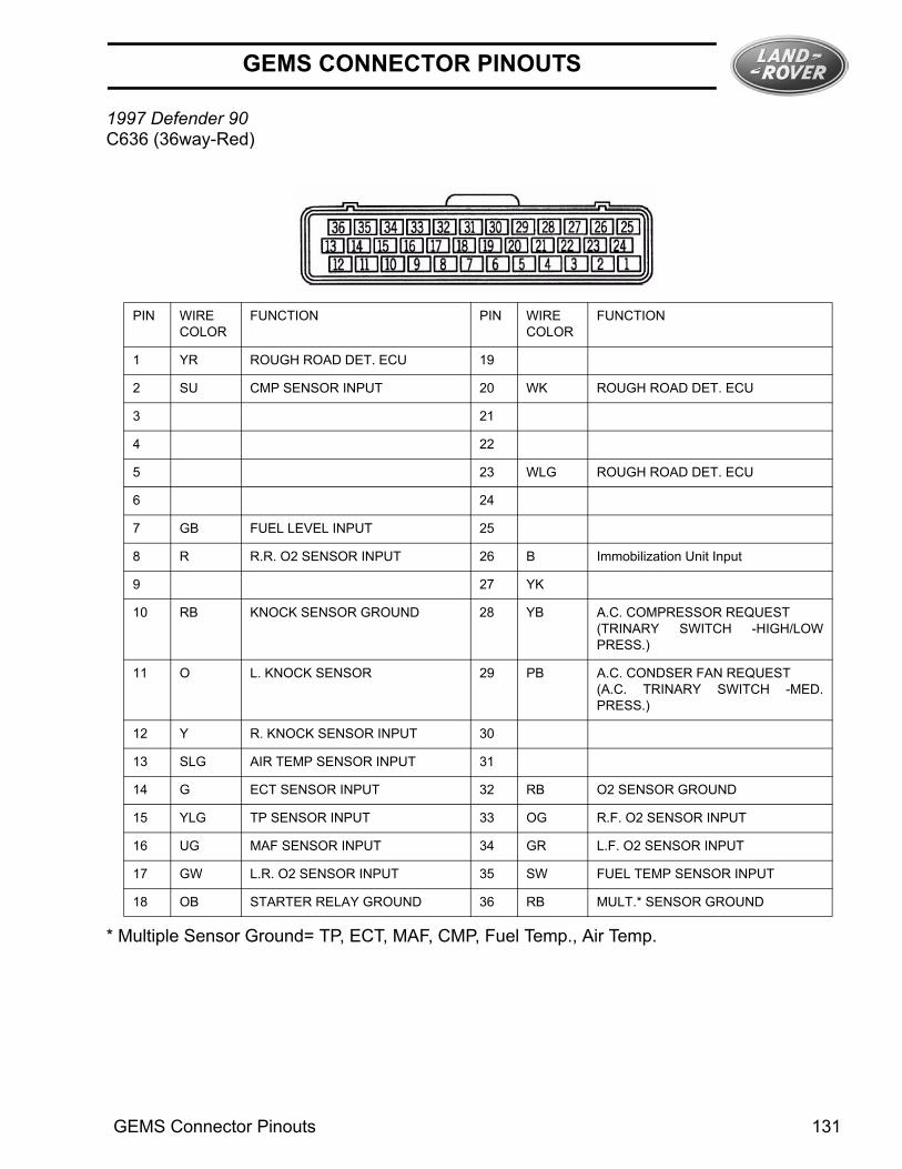
1997 Defender 90C634 (36way-Black)
PIN WIRECOLOR
FUNCTION PIN WIRECOLOR
FUNCTION
1 BS A/C Clutch Relay enable (-) 19 SY Purge Control Valve enable (-)
2 - 20 -
3 GW Cooling Fan Relay enable (-) 21 WO HO2S Upstream Heater Control
4 - 22 RS MIL bulb and Immob. ECU (Output)
5 - 23 -
6 - 24 UP Fuel Pump Relay Control (+)
7 - 25 -
8 - 26 -
9 - 27 -
10 - 28 WU HO2S Downstream Heater Control
11 YB Cylinder #3 Injector Control 29 -
12 - 30 YN Cylinder #4 Injector Control
13 YU Cylinder #1 Injector Control 31 -
14 - 32 YR Cylinder #7 Injector Control
15 US IACV-D 33 YG Cylinder #5 Injector Control
16 RG IACV-B 34 GW IACV-C
17 YS Cylinder #6 Injector Control 35 OR IACV-A
18 YK Cylinder #8 Injector Control 36 YW Cylinder #2 Injector Control
130
GEMS CONNECTOR PINOUTS
1997 Defender 90C636 (36way-Red)
* Multiple Sensor Ground= TP, ECT, MAF, CMP, Fuel Temp., Air Temp.
PIN WIRECOLOR
FUNCTION PIN WIRECOLOR
FUNCTION
1 YR ROUGH ROAD DET. ECU 19
2 SU CMP SENSOR INPUT 20 WK ROUGH ROAD DET. ECU
3 21
4 22
5 23 WLG ROUGH ROAD DET. ECU
6 24
7 GB FUEL LEVEL INPUT 25
8 R R.R. O2 SENSOR INPUT 26 B Immobilization Unit Input
9 27 YK
10 RB KNOCK SENSOR GROUND 28 YB A.C. COMPRESSOR REQUEST (TRINARY SWITCH -HIGH/LOWPRESS.)
11 O L. KNOCK SENSOR 29 PB A.C. CONDSER FAN REQUEST(A.C. TRINARY SWITCH -MED.PRESS.)
12 Y R. KNOCK SENSOR INPUT 30
13 SLG AIR TEMP SENSOR INPUT 31
14 G ECT SENSOR INPUT 32 RB O2 SENSOR GROUND
15 YLG TP SENSOR INPUT 33 OG R.F. O2 SENSOR INPUT
16 UG MAF SENSOR INPUT 34 GR L.F. O2 SENSOR INPUT
17 GW L.R. O2 SENSOR INPUT 35 SW FUEL TEMP SENSOR INPUT
18 OB STARTER RELAY GROUND 36 RB MULT.* SENSOR GROUND
GEMS Connector Pinouts 131

GEMS CONNECTOR PINOUTS
1997 Defender 90C635 (18way-Black)
Heated Oxygen Sensors (HO2S)C644 Left UpstreamC645 Right Upstream
PIN WIRECOLOR
FUNCTION PIN WIRECOLOR
FUNCTION
1 WK Coil Driver Cylinders 5 & 8 10 B Earth C560
2 - 11 G Crank Sensor Negative
3 - 12 N Crank Sensor Positive
4 R TPS 5 volt supply 13 WU Coil Drivers Cylinders 2&3
5 B Earth C560 14 WB Coil Drivers Cylinders 1&6
6 - 15 WY Coil Drivers Cylinders 4&7
7 NO Power Supply from Main Relay 16 B Earth C560
8 WG Fuel Pump Relay enable (-) 17 UR Main Relay Control - enable (-)
9 B Earth C560 18 -
132

GEMS CONNECTOR PINOUTS
C643 Left DownstreamC642 Right Downstream(4-way, Black)
Data Link Connector (X-318)C040 (16-way, Black)
PIN Wire Color Description
C644Left Up-stream
C645Right Up-stream
C643Left Downstream
C642Right Downstream
1 O U Y G HO2S 5 Volt Reference
2 RB RB RB RB HO2S Signal Ground
3 W W W W Heater Power supply
4 WO WO WU WU Heater Control
PIN WIRECOLOR
FUNCTION PIN WIRECOLOR
FUNCTION
1 - 9 -
2 - 10 -
3 - 11 -
4 B Chassis Negative (Header C286,C550)
12 -
5 B Chassis Negative (Header C286,C550)
13 -
6 - 14 -
7 WLG “K”-GEMS, Rough Road Det. ECU 15 WK “L”-GEMS, Rough Road Det. ECU
8 OLG 16 P Battery Positive(Fuse 3-Passen-ger Compartment)
GEMS Connector Pinouts 133
GEMS CONNECTOR PINOUTS
134

GEMS ECM TUNE SUMMARY
GEMS ECM TUNE SUMMARYNOTE: Any of the following tune levels may be valid for the year/model listed. ECM tunes should only be changed according to published service documentation or at the direction of the Technical Help desk, and only due to verified complaint or symptoms. Should a replacement be necessary, only 'Final Service Fix' PROM's should be used unless otherwise directed by Techline.
Model Tune # Description 95MY RR 9612 Production Tune, POE installed.
9613 Production Tune, Line Build.
9638 “Final" Service fix
96MY RR 9618 Original Production Tune
9622 Service Fix for ABS/T-box Link Faults (P1317/1703)
9636 “Final" Service fix
97MY RR 9635 POE fix for Oxy period fix on 4.6L
9639 “Final" Service fix
98MY RR 9648 Original Production Tune (Contains all RR final service fixes)
99MY RR 9648 Original Production Tune (same as 98 MY)
99MY Calloway 9659 Available only with complete ECM
96MY Discovery 9621 Orignial Production Tune - phase 1
9623 Orignial Production Tune - phase 2
9631 Service Fix for ABS Link P1317 and Warm up timer P0125 (both phase 1&2)
9637 “Final" Service fix - Auto trans
9630 “Final" Service fix - Man trans
97MY Discovery 9624 Original Production Tune - Auto trans
9629 Original Production Tune - Man trans
9662 “Final" Service fix - Auto trans
9644 “Final" Service fix - Man trans
97.5MY Discovery w/EVAP Leak Detection
9633 Original Production Tune - Auto trans
9634 Original Production Tune - Man trans
9640 Running change, fix for Idle Surge and Fuel Level Fault P0461
9641 Running change, fix for Idle Surge and Fuel Level Fault P0461
9652 “Final" Service fix - Auto trans
9653 “Final" Service fix - Man trans
98MY Discovery 9652 Original Production Tune - Auto trans (Contains all 97 Discovery final service fixes)
9655 “Final" Service fix - Auto trans
99MYDisco 9655 Original Production Tune - Auto trans (same as 98 MY)
97MY Def 90 9632 Original Production Tune
9661 “Final" Service fix
Range Rover “Final" Service fix tunes will include: Oxy period resolution to driver induced faults, Idle speed improvementpreventing cold hesitation, and Engine Speed Fault (Gbox 21). Improved torque map to prevent Torque Reduction Fault(Gbox 23).
Discovery “Final" Service fix tunes will include: Oxy period resolution to driver induced faults, Trailing Throttle Misfire, Idlespeed improvement preventing cold hesitation, Idle speed fluctuation on decel, Fuel Level Fault P0461.
GEMS ECM Tune Summary 135

GEMS ECM TUNE SUMMARY
Interim Service TunesThe following is a list of unreleased tunes that were sent out by the GEMS Helpline on a case by case basis to correct individual problems.
Each one contains elements of the final service fix, but does not provide the full benefit of a final service fix tune.
Other TunesThe following is a list of tunes that may be encountered in a vehicle, but are not appropriate for the year/model listed.
Model Tune # Description
95 MY RR 4000 Increased Idle speed, Oxy Period fix (P0130/0150)
96 MY RR 4001 Increased Idle speed, Oxy Period fix (P0130/0150)
97 MY RR 4002 Increased Idle speed, Oxy Period fix (P0130/0150)
96 MY Discovery 8173 Increased Idle speed.
96 MY Discovery 568_563 Misfire trailing throttle and Oxy period fix (P0130/0150)
Model Tune # Description
95MY RR 9601 Original Production Tune - never sold
97MY RR 9626 Original Production Tune (All reworked to 9635)
98MY Discovery 9653 Original Production Tune - Man trans (no NAS Man trans built)
136