engine mechanical - dynv12.dyndns.org/toyota/hilux (1985-1994)/chapter3_engine_mechani… ·...
TRANSCRIPT
EM-1
ENGINE MECHANICALPage
TROUBLESHOOTING (22R-E) EM-2'
(22R) EM-5ENGINE TUNE-UP................................................ EM-9
IDLE HC/CO CONCENTRATION CHECKMETHOD EM-10
COMPRESSION CHECK........................................ EM-11
CYLINDER HEAD................................................. EM-12 ImITIMING CHAIN................................................... EM-40
CYLINDER BLOCK........ EM-47
EM-2 ENGINE MECHANICAL - Troubleshooting
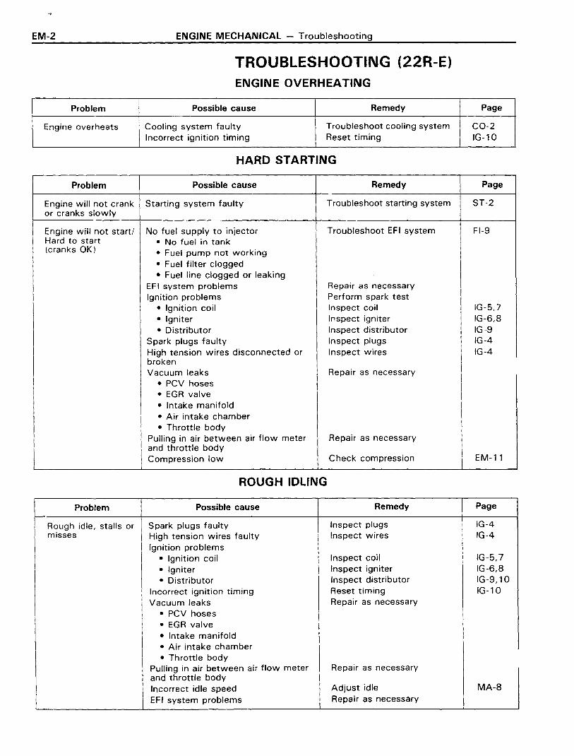
TROUBLESHOOTING (22R-E)ENGINE OVERHEATING
Problem Possible cause Remedy Page
Engine overheats Cooling system faulty Troubleshoot cooling system CO-2Incorrect ignition timing Reset timing IG-10
HARD STARTING
Problem Possible cause Remedy Page
Engine will not crank Starting system faulty Troubleshoot starting system ST-2or cranks slowly
Engine will not start/ No fuel supply to injector Troubleshoot EFI system FI-9Hard to start • No fuel in tank(cranks OK) • Fuel pump not working
• Fuel filter clogged• Fuel line clogged or leaking
EFI system problems Repair as necessaryIgnition problems Perform spark test
• Ignition coil Inspect coil IG-5,7
• Igniter Inspect igniter IG-6,8
• Distributor Inspect distributor IG-9Spark plugs faulty Inspect plugs IG-4High tension wires disconnected or Inspect wires IG-4brokenVacuum leaks Repair as necessary
• PCV hoses• EGR valve• Intake manifold• Air intake chamber• Throttle body
Pulling in air between air flow meter Repair as necessaryand throttle bodyCompression low Check compression EM-11
ROUGH IDLING
Problem Possible cause Remedy Page
Rough idle, stalls or Spark plugs faulty Inspect plugs IG-4misses High tension wires faulty Inspect wires IG-4
Ignition problems• Ignition coil Inspect coil IG-5,7
• Igniter Inspect igniter IG-6,8
• Distributor Inspect distributor IG-9,10Incorrect ignition timing Reset timing IG-10Vacuum leaks Repair as necessary
• PCV hoses• EGR valve• Intake manifold• Air intake chamber• Throttle body
Pulling in air between air flow meter Repair as necessaryand throttle bodyIncorrect idle speed Adjust idle MA-8
EFI system problems Repair as necessary

ENGINE MECHANICAL - Troubleshooting
ROUGH IDLING (CONT'D)
EM-3
Problem Possible cause Remedy Page
Rough idle, stalls or Engine overheats Check cooling system CO-2misses (cont'd) Compression low Check compression EM-11
Incorrect valve clearance Adjust valve clearance MA-7
ENGINE HESITATES/POOR ACCELERATION
Problem Possible cause Remedy Page
Engine hesitates/ Spark plugs faulty Inspect plugs IG-4Poor acceleration High tension wires faulty Inspect wires IG-4
Vacuum leaks Repair as necessary• PCV hoses• EGR valve• Intake manifold• Air intake chamber• Throttle body
Pulling in air between air flow meter Repair as necessaryand throttle bodyIncorrect ignition timing Reset timing IG-10Fuel system clogged Check fuel systemAir cleaner clogged Check air cleanerEF I system problems Repair as necessaryEmission control system problem(cold engine)
• EGR system always on Check EGR system
IEngine overheats Check cooling system CO-2Compression low Check compression EM-11
ENGINE DIESELING
Problem Possible cause Remedy Page
Engine dieseling EFI system problems Repair as necessary(run after ignitionswitch is turned off)
AFTER FIRE, BACKFIRE
Problem Possible cause Remedy Page
Muffler explosion Deceleration fuel cut system always Check EFI (fuel cut) system FI-74(after fire) on offdeceleration only
Muffler explosion Air cleaner clogged Check air cleaner(after fire) all the EFI system problem Repair as necessarytime Incorrect ignition timing Reset timing IG-10
Incorrect valve clearance Adjust valve clearance MA-7
EM-4 ENGINE MECHANICAL - Troubleshooting
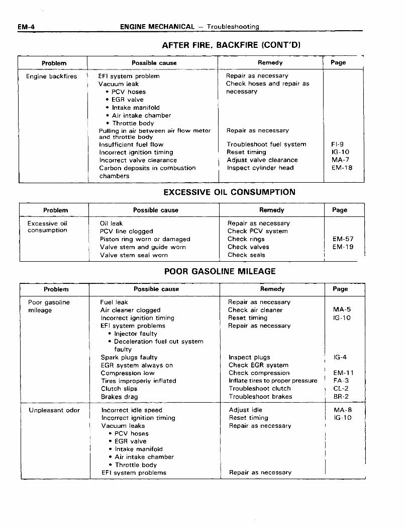
AFTER FIRE, BACKFIRE (CONT'D)...
Problem Possible cause Remedy Page
Engine backfires EFI system problem Repair as necessaryVacuum leak Check hoses and repair as
• PCV hoses necessary
• EGR valve• Intake manifold• Air intake chamber• Throttle body
Pulling in air between air flow meter Repair as necessaryand throttle bodyInsufficient fuel flow Troubleshoot fuel system FI-9Incorrect ignition timing Reset timing IG-10Incorrect valve clearance Adjust valve clearance MA-7Carbon deposits in combustion Inspect cylinder head EM-18chambers
EXCESSIVE OIL CONSUMPTION
Problem Possible cause Remedy Page
Excessive oil Oil leak Repair as necessaryconsumption PCV line clogged Check PCV system
Piston ring worn or damaged Check rings EM-57Valve stem and guide worn Check valves EM-19Valve stem seal worn Check seals
POOR GASOLINE MILEAGE
Problem Possible cause Remedy Page
Poor gasoline Fuel leak Repair as necessarymileage Air cleaner clogged Check air cleaner MA-5
Incorrect ignition timing Reset timing IG-10EFI system problems Repair as necessary
• Injector faulty• Deceleration fuel cut system
faultySpark plugs faulty Inspect plugs IG-4EGR system always on Check EGR systemCompression low Check compression EM-11Tires improperly inflated Inflate tires to proper pressure FA-3Clutch slips Troubleshoot clutch CL-2Brakes drag Troubleshoot brakes BR-2
Unpleasant odor Incorrect idle speed Adjust idle MA-8Incorrect ignition timing Reset timing IG-10Vacuum leaks Repair as necessary
• PCV hoses• EGR valve• Intake manifold• Air intake chamber• Throttle body
EF I system problems Repair as necessaryI

ENGINE MECHANICAL - Troubleshooting
TROUBLESHOOTING (22R)ENGINE OVERHEATING
EM-5
Problem Possible cause Remedy Page
Engine overheats Cooling system faulty Troubleshoot cooling system CO-2Incorrect ignition timing Reset timing IG-10
HARD STARTING
Problem Possible cause Remedy Page
Engine will not crank Starting system faulty Troubleshoot starting system ST-2or cranks slowly
Engine will not start/ No fuel supply to carburetor Troubleshoot fuel system FU-2Hard to start Carburetor problems Repair as necessary FU-4(cranks OK) • Choke operating
• Flooding• Needle valve sticking or clogged• Vacuum hose disconnected or
damaged• Fuel cut solenoid valve not open• Secondary throttle valve not
closeIgnition problems Perform spark test IG-4
• Ignition coil Inspect coil IG-5,7• Igniter Inspect igniter IG-6,8• Distributor Inspect distributor IG-9, 10
Spark plugs faulty Inspect plugs IG-4Ignition wiring disconnected or broken Inspect wiring IG-4Vacuum leaks Repair as necessary
• PCV line• EGR line• MC line• Intake manifold• CMH
Compression low Chek compression EM-11
ROUGH IDLING
Problem Possible cause Remedy Page
Rough idle or stalls Spark plugs faulty Inspect plugs IG-4Ignition wiring faulty Inspect wiring IG-4Vacuum leaks Repair as necessary
• PCV line• Me line• EGR line• Intake manifold• HAC line• CMH
Incorrect ignition timing Reset timing IG-10Ignition problems Perform spark test IG-4
• Ignition coil Inspect coil IG-5,7
• Igniter Inspect igniter IG-6,8
• Distributor Inspect distributor IG-9, 10

EM-6 ENGINE MECHANICAL - Troubleshooting
ROUGH IDLING (CONT'D)
Problem Possible cause Remedy Page
Rough idle or stalls Carburetor problems Perform on-vehicle FU-3• Id Ie speed incorrect inspection of carburetor• Slow jet clogged• Idle mixture incorrect• Fuel cut solenoid valve not open• Fast idle speed setting incorrect
(cold engine)• Choke system faulty
HAl system faulty Check compression EC-53Engine overheats Troubleshoot cooling system CO-2EGR valve faulty Check EGR valve EC-30MC valve faulty Check MC valve EC-26Incorrect valve clearance Adjust valve clearance MA-7Compression low Check compression EM-ll
ENGINE HESITATES/POOR ACCELERATION
Problem Possible cause Remedy Page
Engine hesitates/ Spark plugs faulty Inspect plugs IG-4Poor acceleration Ignition wiring faulty Inspect wiring IG-4
Vacuum leaks Repair as necessary• PCV line• EGR line• HAC line• Intake manifold
• CMH• MC
Incorrect ignition timing Reset timing IG-10Air filter clogged Check air filter MA-5Fuel line clogged Check fuel lineCarburetor problems Repair as necessary FU-4
• Float level too low• Accelerator pump faulty• Power valve faulty• Choke valve closed (hot engine)• Choke system• Secondary throttle stopper
operation faulty (cold engine)CMH system faulty (cold engine)Emission control system problem
• HA I system always on Check HAl system EC-53(hot engine)
• AAP system faulty Check AAP system EC-61• EGR system always on Check EGR system EC-30
(cold engine)• HAC system faulty Check HAC system EC-48
Engine overheats Check cooling system CO-2Compression low Check compression EM-ll
ENGINE MECHANICAL - Troubleshooting
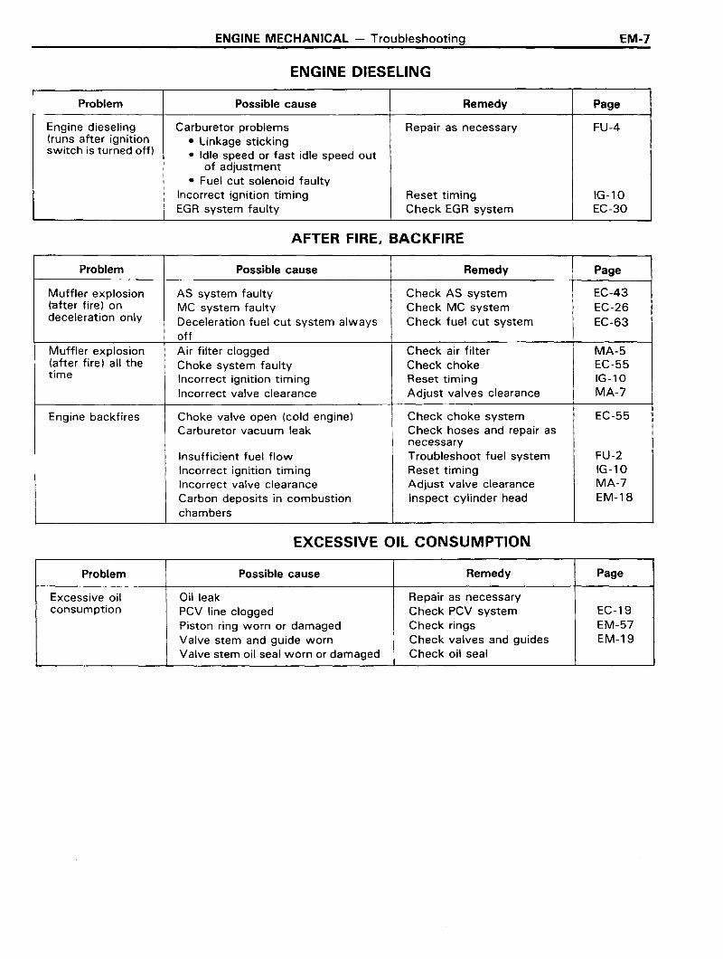
ENGINE DIESELING
EM-7
rProblem Possible cause Remedy Page
Engine dieseling Carburetor problems Repair as necessary FU-4(runs after ignition • Linkage stickingswitch is turned off) • Idle speed or fast idle speed out
of adjustment• Fuel cut solenoid faulty
Incorrect ignition timing Reset timing IG-l0EGR system faulty Check EGR system EC-30
AFTER FIRE, BACKFIRE
Problem Possible cause Remedy Page
Muffler explosion AS system faulty Check AS system EC-43(after fire) on MC system faulty Check MC system EC-26deceleration only Deceleration fuel cut system always Check fuel cut system EC-63
offMuffler explosion Air filter clogged Check air filter MA-5(after fire) all the Choke system faulty Check choke EC-55time Incorrect ignition timing Reset timing IG-10
Incorrect valve clearance Adjust valves clearance MA-7
Engine backfires Choke valve open (cold engine) Check choke system EC-55Carburetor vacuum leak Check hoses and repair as
necessaryInsufficient fuel flow Troubleshoot fuel system FU-2Incorrect ignition timing Reset timing IG-l0Incorrect valve clearance Adjust valve clearance MA-7Carbon deposits in combustion Inspect cylinder head EM-18chambers
EXCESSIVE OIL CONSUMPTION
Problem Possible cause Remedy Page
Excessive oil Oil leak Repair as necessaryconsumption PCV line clogged Check PCV system EC-19
Piston ring worn or damaged Check rings EM-57Valve stem and guide worn Check valves and guides EM-19Valve stem oil seal worn or damaged Check oil seal
EM-8 ENGINE MECHANICAL - Troubleshooting
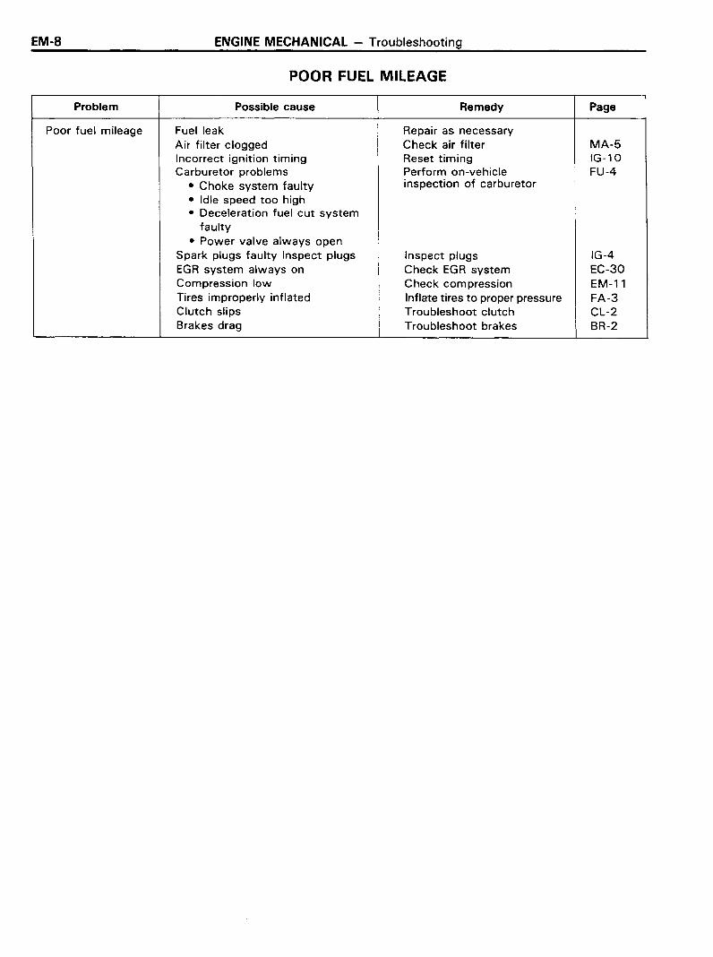
POOR FUEL MILEAGE,
Problem Possible cause Remedy Page
Poor fuel mileage Fuel leak Repair as necessaryAir filter clogged Check air filter MA-5Incorrect ignition timing Reset timing IG-10Carburetor problems Perform on-vehicle FU-4
• Choke system faulty inspection of carburetor
• Idle speed too high• Deceleration fuel cut system
faulty• Power valve always open
Spark plugs faulty Inspect plugs Inspect plugs IG-4EGR system always on Check EGR system EC-30Compression low Check compression EM-11Tires improperly inflated Inflate tires to proper pressure FA-3Clutch slips Troubleshoot clutch CL-2Brakes drag Troubleshoot brakes BR-2
ENGINE MECHANICAL - Engine Tune-Up
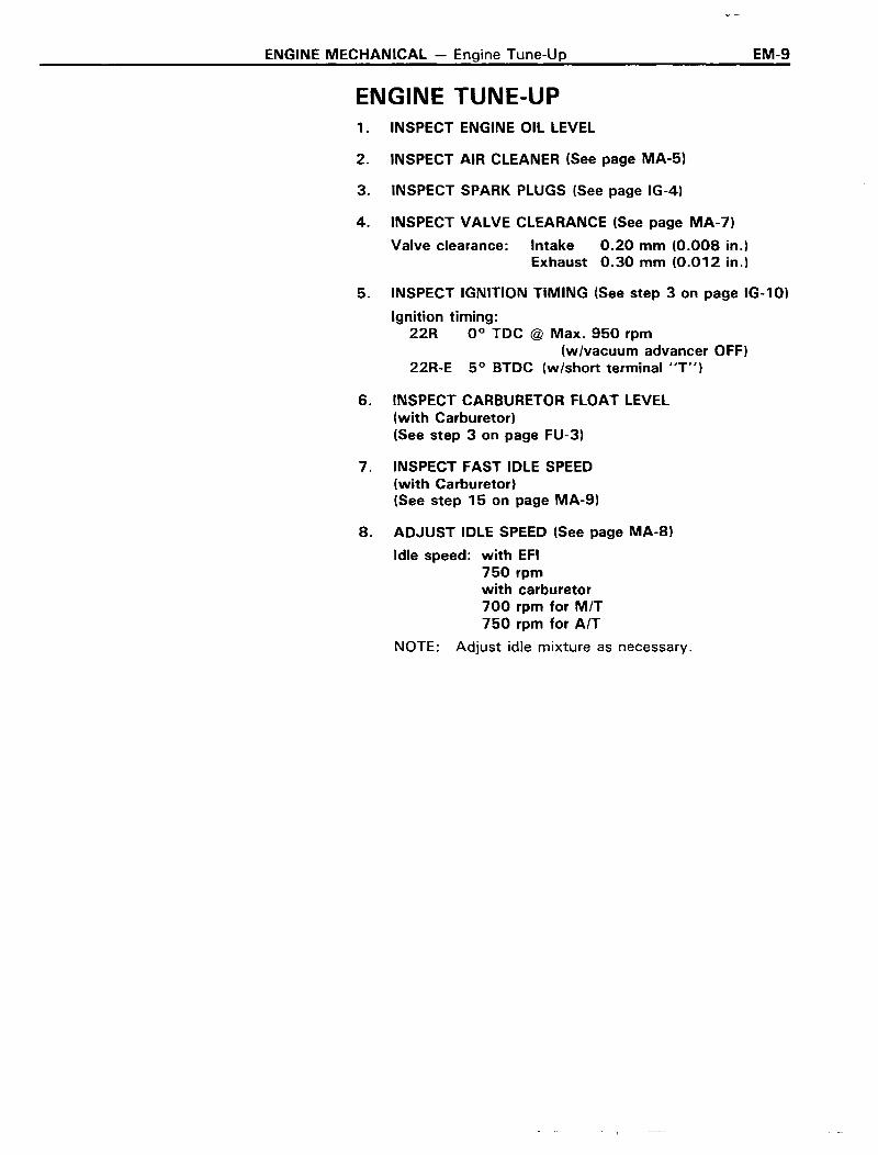
ENGINE TUNE-UP1. INSPECT ENGINE OIL LEVEL
2. INSPECT AIR CLEANER (See page MA-5)
3. INSPECT SPARK PLUGS (See page IG-4)
4. INSPECT VALVE CLEARANCE (See page MA-7)
Valve clearance: Intake 0.20 mm (0.008 in.)Exhaust 0.30 mm (0.012 in.)
EM-9
5. INSPECT IGNITION TIMING (See step 3 on page IG-10)
Ignition timing:22R 0° TDC @ Max. 950 rpm
(wIvacuum advancer OFF)22R-E 5° BTDC (w/short terminal liT")
6. INSPECT CARBURETOR FLOAT LEVEL(with Carburetor)(See step 3 on page FU-3)
7. INSPECT FAST IDLE SPEED(with Carburetor)(See step 15 on page MA-9)
8. ADJUST IDLE SPEED (See page MA-8)
Idle speed: with EFI750 rpmwith carburetor700 rpm for MIT750 rpm for AIT
NOTE: Adjust idle mixture as necessary.

EM-10 ENGINE MECHANICAL - Idle HC/CO Concentration Check Method
IDLE HC/CO CONCENTRATION CHECK METHODNOTE: This check method is used only todetermine whether or not the idle HC/CO complies with regulations.
PRECHECKINITIAL CONDITIONS
(a) Normal engine operating temperature
(b) Choke fully open (with carburetor)
(c) Air cleaner installed
(d) All pipe and hoses of air intake systemconnected (with EFI)
(e) All accessories switched off
(f) All vacuum lines properly connected
(g) EFI system wiring connectors fullyplugged.
(h) Idle speed set correctly
TROUBLESHOOTING
(i) Carburetor fuel level about even with ~.
correct level in the sight glass
(j) Tachometer and HC/CO meter calibratedand at hand
MEASUREMENT1. INSERT TESTING PROBE OF HC/CO METER
INTO TAILPIPE AT LEAST 40 em (1.3 ft)
2. MEASURE HC/CO CONCENTRATION AT IDLE
Wait at least one minute before measuring toallow the concentration to stabilize.
Complete the measuring within three minutes.
If the HC/CO concentration does not conformto regulation, see the table below for possible causes.
HC CO Problems Causes
High Normal Rough idle 1. Faulty ignition:• Incorrect timing• Fouled, shorted or improperly gapped plugs• Open or crossed ignition wires• Cracked distributor cap
2. Incorrect valve clearance3. Leaky EGR valve4. Leaky exhaust valves5. Leaky cylinder
High Low Rough idle 1. Vacuum leak:• Vacuum hose
Fluctuating HC reading • Intake manifold• Air chamber (with EFI)• PCV line• Carburetor base (with carburetor)• Throttle body (with EFI)• CMH (with carburetor)
2. Leaky MC valve (with carburetor)
High High Rough idle 1. Restricted air filter2. Plugged PCV valve3. AS system problem (with carburetor)
Black smoke from exhaust 4. Faulty carburetion: (with carburetor)• Faulty choke action• Incorrect float setting• Leaking needle or seat• Leaking power valve
5. Faulty EFI system: (with EFI)• Faulty pressure regulator• Clogged fuel return line• Faulty air flow meter• Defective water thermo sensor• Defective air thermo sensor• Faulty EFI computer• Faulty injector• Faulty cold start injector

ENGINE MECHANICAL - Compression Check
COMPRESSION CHECK
EM-11
NOTE: If there is lack of power, excessive oil consumption or poor fuel mileage, measure the cylinder compression pressure.
1. WARM UP ENGINE
2. REMOVE FOUR SPARK PLUGS
3. DISCONNECT HIGH TENSION WIRE FROM IGNITION COIL
4. MEASURE CYLINDER COMPRESSION PRESSURE
(a) Insert a compression gauge into the spark plug hole.
(b) Fully open the throttle.
(c) While cranking the engine with the starter motor,measure the compression pressure.
CAUTION: This test must be done for as short a time aspossible to avoid overheating of the catalytic converter.
NOTE: A fully changed battery must be used to obtainat least 250 rpm.
(d) Repeat steps (a) through (c) for each cylinder.
Compression pressure: 12 kg/cm2 (171 psi, 1,177 kPa)Minimum pressure: 10 kg/cm2 (142 psi, 981 kPa)Difference between each cylinder:
Less than 1.0 kg/cm2 (14 psi,98 kPa)
(e) If cylinder compression in one or more cylinders is low,pour a small amount of engine oil into the cylinderthrough the spark plug hole and repeat steps (a)through (e) for the low compression cylinder.
• If adding oil helps the compression, chances are thatthe piston rings and/or cylinder bore are worn ordamaged.
• If pressure stays low, a valve may be sticking orseating improperly, or there may be leakage pastthe gasket.
EM-12
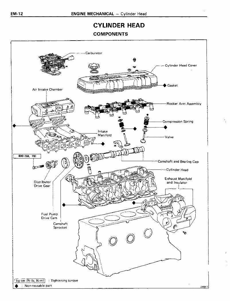
Air Intake Chamber
rDistributorDrive Gear
Fuel PumpDrive Cam
CamshaftSprocket
ENGINE MECHANICAL - Cylinder Head
CYLINDER HEADCOMPONENTS
....-----Carburetor
Cylinder Head Cover
~~~\~ ~~~~iIr~,--RockerArm Assembly
~~~
---Compression Spring
•----Valve
Camshaft and Bearing Cap
r-----Cylinder Head
I kg-cm (ft-Ib, N·m) I : Tightening torque
• : Non-reusable part EM0817

ENGINE MECHANICAL - Cylinder Head
22R-EPREPARATION FOR REMOVAL
EM-13
1. DISCONNECT CABLE FROM NEGATIVE TERMINAL OFBATTERY
2. DRAIN COOLANT FROM RADIATOR AND CYLINDERBLOCK
3. DRAIN ENGINE OIL
4. REMOVE AIR CLEANER HOSE
5. DISCONNECT EXHAUST PIPE FROM EXHAUSTMANIFOLD
(a) Disconnect the Ox sensor wire.
(b) Remove three nuts holding exhaust manifold to theexhaust pipe.
6. DISCONNECT RADIATOR UPPER HOSE FROM THERMOSTAT HOUSING
7. DISCONNECT TWO HEATER HOSES
8. DISCONNECT ACCELERATOR CABLE
Disconnect the accelerator cable and throttle cable for AfTfrom the bracket.
9. DISCONNECT FOLLOWING PARTS:
(a) PCV hoses No.1 and No.2
(b) Brake booster hose
(c) Air control valve hoses
(d) EVAP hose (from canister)
(e) Actuator hose (with cruise control)
(f) EGR vacuum modulator hose
(g) Air valve hose No.1 from the throttle body
(h) Air valve hose No.2 from the chamber
(i) Water by-pass hoses No.2 and No.3 from thethrottle body
(j) Air control valve hose for actuator
(k) Pressure regulator hose from the chamber
(I) Cold start injection pipe
(m) BVSV hoses
10. DISCONNECT FOLLOWING WIRES:
(a) Cold start injection wire
(b) Throttle position wire
(c) Air valve wire

EM-14 ENGINE MECHANICAL - Cylinder Head
11. REMOVE CHAMBER WITH THROTTLE BODY
(a) Remove the bolt holding the EGR valve to thp.chamber.
(b) Disconnect the chamber and stay.
(c) Remove the bolts and nuts holding the chamber to theintake manifold.
(d) Remove the chamber with the throttle body.
12. DISCONNECT FOLLOWING WIRES:
(a) Water temperature sender gauge wire
(b) Temperature sensor wire
(c) Start injection time switch wire
(d) OD thermo switch wire (with AfT)
(e) Injection wires
13. DISCONNECT FUEL HOSE FROM DELIVERY PIPE
(a) Remove the pulsation damper.
(b) Remove the bolt holding the fuel hose to the deliverypipe.
(c) Disconnect the fuel hose from the delivery pipe.
14. REMOVE AIR VALVE FROM INTAKE MANIFOLD
(a) Disconnect the NO.4 by-pass hose.
(b) Remove the air valve from intake manifold.
15. DISCONNECT BY-PASS HOSE FROM INTAKE MANIFOLD
16. REMOVE DISTRIBUTOR AND SPARK PLUGS
17. DISCONNECT BOND CABLE FROM VANE PUMP BRACKET
\
FI0020
18. IF VEHICLE HAS POWER STEERING, REMOVE VANEPUMP WITH BRACKET
(a) Disconnect the vacuum hose from the air controlvalve.
(b) Loosen and remove the drive belt.
(c) Remove the vane pump to one side without disconnecting the hoses.
19. DISCONNECT BOND CABLE ON REAR SIDE
ENGINE MECHANICAL - Cylinder Head EM-15
EM0815
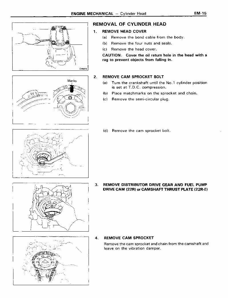
REMOVAL OF CYLINDER HEAD
1. REMOVE HEAD COVER
(a) Remove the bond cable from the body.
(b) Remove the four nuts and seals.
(c) Remove the head cover.
CAUTION: Cover the oil return hole in the head with arag to prevent objects from falling in.
Marks2. REMOVE CAM SPROCKET BOLT
(a) Turn the crankshaft until the No.1 cylinder positionis set at T.O.C. compression.
(b) Place matchmarks on the sprocket and chain.
(c) Remove the semi-circular plug.
(d) Remove the cam sprocket bolt.
3. REMOVE DISTRIBUTOR DRIVE GEAR AND FUEL PUMPDRIVE CAM (22R) or CAMSHAFT THRUST PLATE (22R-E)
4. REMOVE CAM SPROCKET
Remove the cam sprocket and chain from the camshaft andleave on the vibration damper.
EM-16 ENGINE MECHANICAL - Cylinder Head
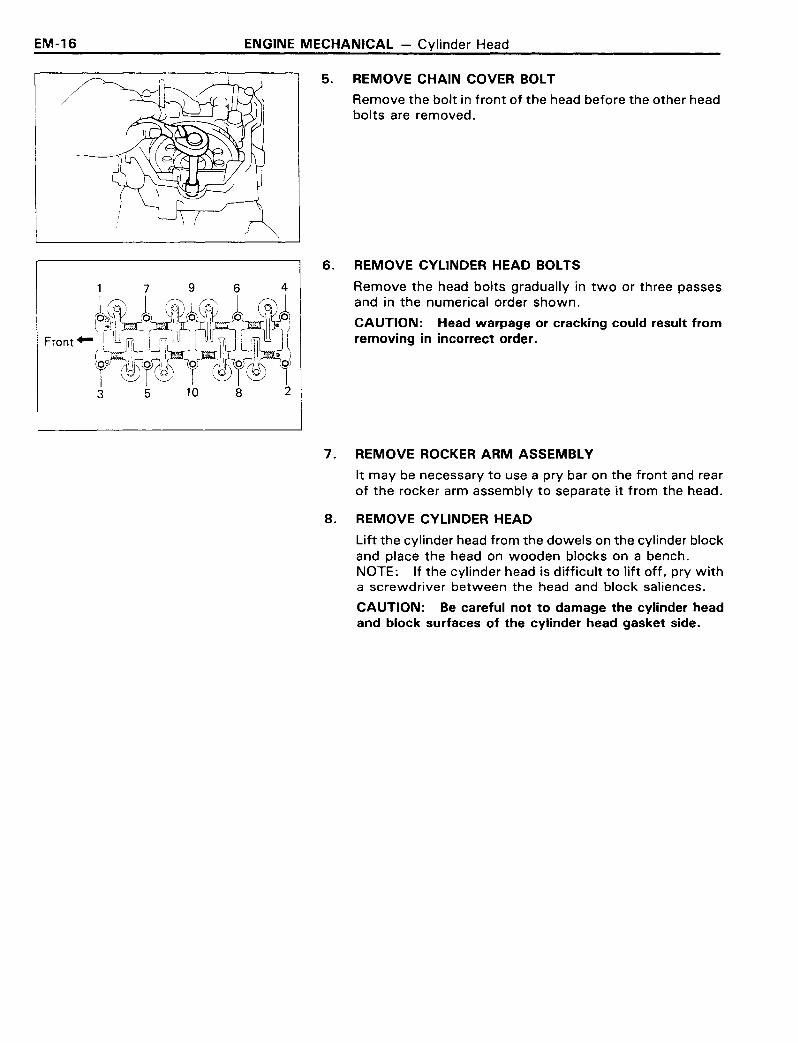
5. REMOVE CHAIN COVER BOLT
/ Remove the bolt in front of the head before the other headbolts are removed.
Front'"
7 9 6 4
6. REMOVE CYLINDER HEAD BOLTS
Remove the head bolts gradually in two or three passesand in the numerical order shown.
CAUTION: Head warpage or cracking could result fromremoving in incorrect order.
7. REMOVE ROCKER ARM ASSEMBLY
It may be necessary to use a pry bar on the front and rearof the rocker arm assembly to separate it from the head.
8. REMOVE CYLINDER HEAD
Lift the cylinder head from the dowels on the cylinder blockand place the head on wooden blocks on a bench.NOTE: If the cylinder head is difficult to lift off, pry witha screwdriver between the head and block saliences.
CAUTION: Be careful not· to damage the cylinder headand block surfaces of the cylinder head gasket side.

ENGINE MECHANICAL - Cylinder Head EM-17
!/
SST---"+
DISASSEMBLY OF CYLINDER HEAD(See page EM-12)
1. REMOVE INTAKE MANIFOLD WITH DELIVERY PIPE ANDINJECTION NOZZLE
(a) Remove the six bolts, one hexagon bolt and two nuts.
(b) Remove the intake manifold together with the deliv-ery pipe and the injection nozzles.
2. REMOVE EGR VALVE WITH VACUUM MODULATORFROM CYLINDER HEAD
3. REMOVE EXHAUST MANIFOLD FROM CYLINDER HEAD
4. MEASURE CAMSHAFT THRUST CLEARANCE
Using a feeler gauge, measure the camshaft thrustclearance between the thrust bearing and camshaft.
If clearance is greater than the maximum, replace the head.
Maximum clearance: 0.25 mm (0.010 in.)Standard clearance: 0.08 - 0.18 mm
(0.003 - 0.007 in.)
5. REMOVE CAM BEARING CAPS AND SHAFT
6. REMOVE VALVES
(a) Using SST, compress the valve retainer until the twokeepers can be removed.
SST 09202-43013
(b) Remove the valve keepers, retainers, springs andvalves.
(c) Remove the valve seals.
(d) Using a small screwdriver or magnet, remove the valvespring seats.
NOTE: Keep the valves arranged so they can be installed in the same order as removed.
EM-18 ENGINE MECHANICAL - Cylinder Head
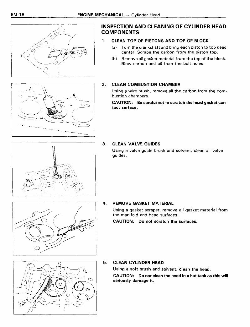
INSPECTION AND CLEANING OF CYLINDER HEADCOMPONENTS
1. CLEAN TOP OF PISTONS AND TOP OF BLOCK
(a) Turn the crankshaft and bring each piston to top deadcenter. Scrape the carbon from the piston top.
(b) Remove all gasket material from the top of the block.Blow carbon and oil from the bolt holes.
2.
3.
4.
5.
CLEAN COMBUSTION CHAMBER
Using a wire brush, remove all the carbon from the combustion chambers.
CAUTION: Be careful not to scratch the head gasket contact surface.
CLEAN VALVE GUIDES
Using a valve guide brush and solvent, clean all valveguides.
REMOVE GASKET MATERIAL
Using a gasket scraper, remove all gasket material fromthe manifold and head surfaces.
CAUTION: Do not scratch the surfaces.
CLEAN CYLINDER HEAD
Using a soft brush and solvent, clean the head.
CAUTION: Do not clean the head in a hot tank as this willseriously damage it.
ENGINE MECHANICAL - Cylinder Head EM-19
6.
7.
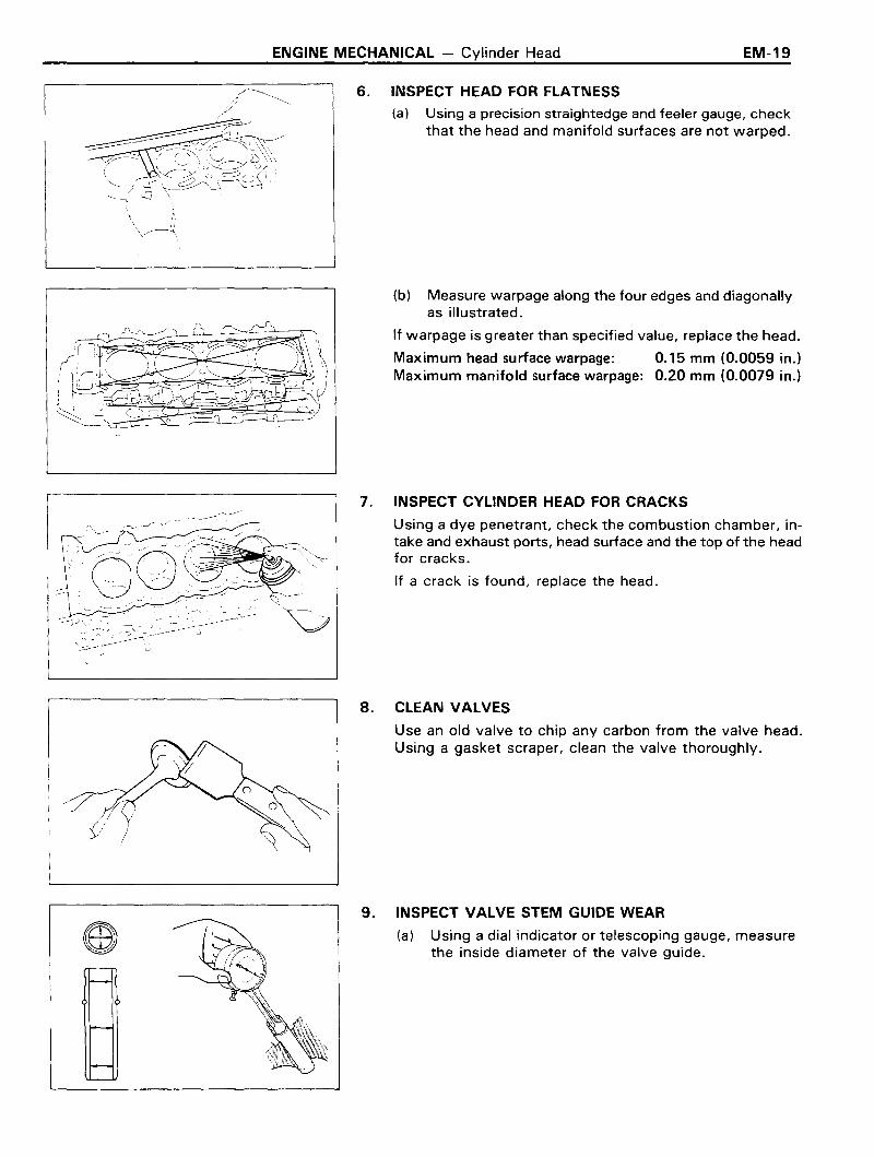
INSPECT HEAD FOR FLATNESS
(a) Using a precision straightedge and feeler gauge, checkthat the head and manifold surfaces are not warped.
(b) Measure warpage along the four edges and diagonallyas illustrated.
If warpage is greater than specified value, replace the head.
Maximum head surface warpage: 0.15 mm (0.0059 in.)Maximum manifold surface warpage: 0.20 mm (0.0079 in.)
INSPECT CYLINDER HEAD FOR CRACKS
Using a dye penetrant, check the combustion chamber, intake and exhaust ports, head surface and the top of the headfor cracks.
If a crack is found, replace the head.
8. CLEAN VALVES
Use an old valve to chip any carbon from the valve head.Using a gasket scraper, clean the valve thoroughly.
9. INSPECT VALVE STEM GUIDE WEAR
(a) Using a dial indicator or telescoping gauge, measurethe inside diameter of the valve guide.

EM-20 ENGINE MECHANICAL - Cylinder Head
+ (b) Using a micrometer, measure the diameter of the valvestem.
(c) Subtract the valve stem measurement from the vaguide measurement.
If the clearance is greater than the following values, replacethe valve and guide:
Maximum intake clearance: 0.08 mm (0.0031 in.)Maximum exhaust clearance: 0.10 mm (0.0039 in.)
10. IF NECESSARY, REPLACE VALVE GUIDE
(a) Using a brass punch and hammer, break the valveguide.
(b) Heat the cylinder head to about 90°C (194°F).
(c) Using SST and hammer, drive out the valve guide.
SST 09201-60011
(d) Heat the cylinder head to about 90°C (194°F).
(e) Using SST and hammer, drive in a new valve guideuntil the snap ring makes contact with the cylinderhead.
SST 09201-60011
ENGINE MECHANICAL - Cylinder Head EM-21
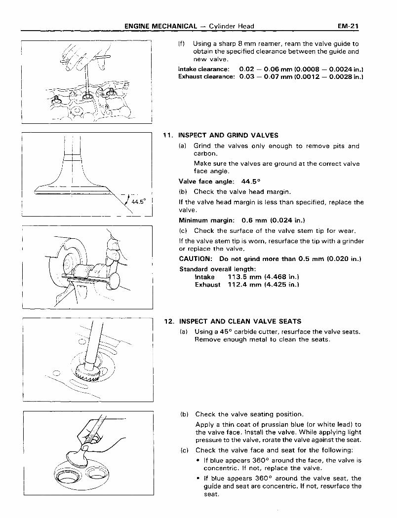
(f) Using a sharp 8 mm reamer, ream the valve guide toobtain the specified clearance between the guide andnew valve.
Intake clearance: 0.02 - 0.06 mm (0.0008 - 0.0024 in.)Exhaust clearance: 0.03 - 0.07 mm (0.0012 - 0.0028 in.)
11. INSPECT AND GRIND VALVES
(a) Grind the valves only enough to remove pits andcarbon.
Make sure the valves are ground at the correct valveface angle.
Valve face angle: 44.5 0
(b) Check the valve head margin.
If the valve head margin is less than specified, replace thevalve.
Minimum margin: 0.6 mm (0.024 in.)
(c) Check the surface of the valve stem tip for wear.
If the valve stem tip is worn, resurface the tip with a grinderor replace the valve.
CAUTION: Do not grind more than 0.5 mm (0.020 in.)
Standard overall length:Intake 113.5 mm (4.468 in.)Exhaust 112.4 mm (4.425 in.)
12. INSPECT AND CLEAN VALVE SEATS
(a) Using a 45 0 carbide cutter, resurface the valve seats.Remove enough metal to clean the seats.
(b) Check the valve seating position.
Apply a thin coat of prussian blue (or white lead) tothe valve face. Install the valve. While applying lightpressure to the valve, rorate the valve against the seat.
(c) Check the valve face and seat for the following:
• If blue appears 360 0 around the face, the valve isconcentric. If not, replace the valve.
• If blue appears 360 0 around the valve seat, theguide and seat are concentric. If not, resurface theseat.

EM-22 ENGINE MECHANICAL - Cylinder Head
Squareness Limit
• Check that the seat contact is on the middle of thevalve face with the following width:
1.2 - 1.6 mm (0.047 - 0.063 in.)
If not, correct the valve seat as follows:
If seating is too high on the valve face, use 30°and 45° cutters to correct the seat.
If seating is too Iowan the valve face, use 60°(IN) or 65° (EX) and 45° cutters to correct theseat.
(d) Hand-lap the valve and valve seat together withabrasive compound.
(e) Clean the valve and valve seat after hand-lapping.
13. INSPECT VALVE SPRINGS
(a) Using a steel square, check the squareness of thevalve springs. If a spring is out of square more thanthe maximum allowable, replace the spring.
Maximum allowable: 1.6 mm (0.063 in.)
(b) Measure the free height of all springs. Replace anyspring that is not correct.
Free height: 48.5 mm (1.909 in.)
(c) Using a spring tester, check the tension of each springat the specified installed height.
If the installed tension is less than the minimum, replacethe spring.
Installed height: 40.5 mm (1.594 in.)Minimum installed tension: 28.5 kg (62.8 Ib, 279 N)

ENGINE MECHANICAL - Cylinder Head EM-23
--_.----~------~
M2503
Z5026
14. INSPECT CAMSHAFT AND BEARING CAPS
(a) Using a micrometer, measure the cam lobes.
If the lobe height is less than the minimum allowable, thecamshaft is worn and must be replaced.
Minimum intake lobe height: 42.63 - 42.72 mm(1.6783 - 1.6819 in.)
Minimum exhaust lobe height: 42.69 - 42.78 mm(1.6807 - 1.6842 in.)
(b) Place the camshaft on V -blocks and measure therunout at the center journal.
If the runout is greater than the maximum allowable, replacethe camshaft.
Maximum circle runout: 0.2 mm (0.008 in.)
(c) Using a micrometer, measure the journal diameter.Standard diameter: 32.98 - 33.00 mm
(1.2984 - 1.2992 in.)
(d) Measure the camshaft journal oil clearance.
• Clean the bearing caps and camshaft journal.
• Lay a strip of Plastigage across each journal.
aIN
I~
a
• Install the correct numbered bearing cap on eachjournal with the arrows pointing toward the front.Torque each bolt.
Torque: 200 kg-cm (14 ft-Ib, 20 N·m)
NOTE: Do not turn the camshaft while the Plastigage isin place.
Maximum clearance:Standard clearance:
EM-24 ENGINE MECHANICAL - Cylinder Head
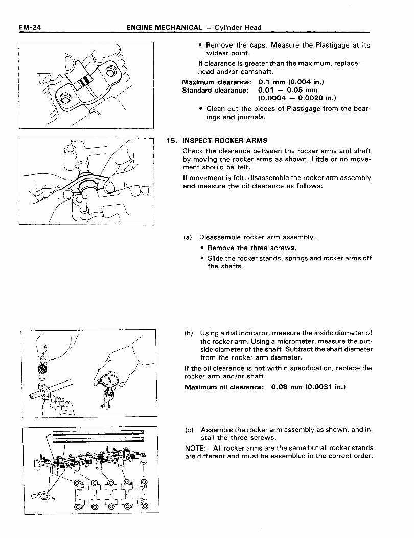
• Remove the caps. Measure the Plastigage at itswidest point.
If clearance is greater than the maximum, replace,head and/or camshaft.
0.1 mm (0.004 in.)0.01 - 0.05 mm(0.0004 - 0.0020 in.)
• Clean out the pieces of Plastigage from the bearings and journals.
15. INSPECT ROCKER ARMS
Check the clearance between the rocker arms and shaftby moving the rocker arms as shown. Little or no movement should be felt.
If movement is felt, disassemble the rocker arm assemblyand measure the oil clearance as follows:
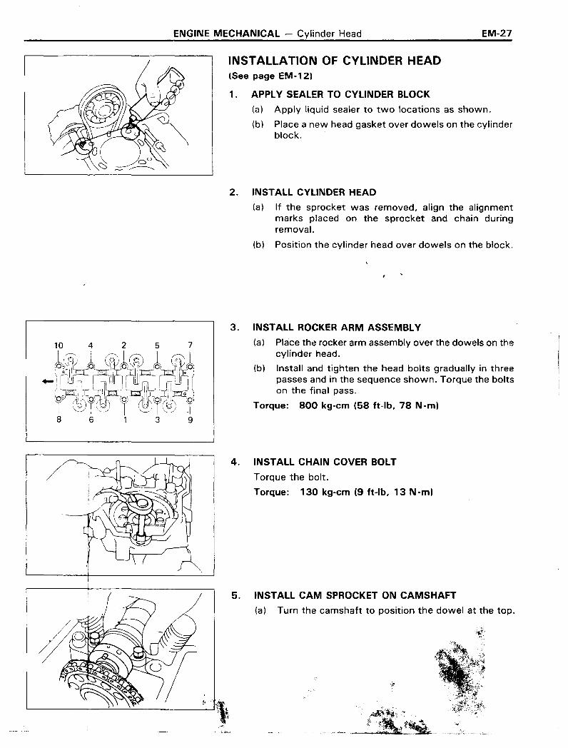
(a) Disassemble rocker arm assembly.
• Remove the three screws.
• Slide the rocker stands, springs and rocker arms offthe shafts.
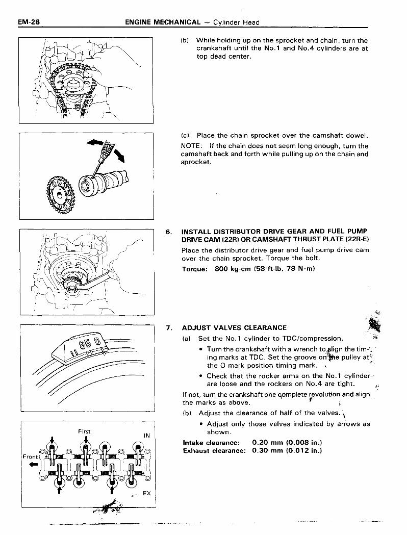
(b) Using a dial indicator, measure the inside diameter ofthe rocker arm. Using a micrometer, measure the outside diameter of the shaft. Subtract the shaft diameterfrom the rocker arm diameter.
If the oil clearance is not within specification, replace therocker arm and/or shaft.
Maximum oil clearance: 0.08 mm (0.0031 in.)
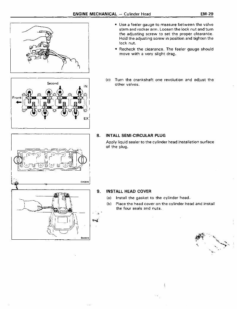
(c) Assemble the rocker arm assembly as shown, and install the three screws.
NOTE: All rocker arms are the same but all rocker standsare different and must be assembled in the correct order.

ENGINE MECHANICAL - Cylinder Head EM-25
16. INSPECT INTAKE AND EXHAUST MANIFOLDS
Using a precision straightedge and feeler gauge, check thesurfaces contacting the cylinder head for warpage. If warpage is greater than maximum, replace the manifold.
Maximum intake warpage: 0.20 mm (0.0079 in.)Maximum exhaust warpage: 0.70 mm (0.0276 in.)
M5456
ASSEMBLY OF CYLINDER HEAD(See page EM-12)
NOTE:• Thoroughly clean all parts to be assembled.
• Before installing the parts, apply new engine oil to allsliding and rotating surfaces.
• Replace all gaskets and oil seals with new parts.
SST--""
1. INSTALL VALVES
(a) Lubricate and insert valves in the cylinder head valveguides. Make sure the valves are installed in the correct order.
(b) Install the valve spring seats and seals.
(c) Install springs and spring retainers on the valves.
(d) Using SST, compress valve retainers and place twokeepers around the valve stem.
SST 09202-43013
(e) Tap the stem lightly to assure proper fit.

EM-26 ENGINE MECHANICAL - Cylinder Head
2. INSTALL CAMSHAFT
(a) Place the camshaft in the cylinder head and install thp.bearing caps in numbered order from the front VI.
arrows pointing toward the front.
(b) Install and torque the cap bolts.
Torque: 200 kg-em (14 ft-Ib, 20 N·m)
3. INSTALL INTAKE MANIFOLD
(a) Position a new gasket on the cylinder head.
(b) Install the intake manifold with the delivery pipe andinjection nozzles.
(c) Install the six bolts, one hexagon bolt and two nuts.Torque the bolts and nuts.
Torque: 195 kg-em (14 ft-Ib, 19 N·m)
4. INSTALL EGR VALVE WITH VACUUM MODULATOR
(a) Position a new gasket on the cylinder head.
(b) Apply a sealer to the upper right bolt.
(c) Place the EGR with vacuum modulator valve in t~
installed position and tighten the two bolts on the intake manifold side of EGR pipe.
(cp Install the vacuum hose to the top of the EGR valve.
5. INSTALL EXHAUST MANIFOLD
(a) Position a new gasket on the cylinder head.
(b) Install the exhaust manifold with eight nuts.Torque the nuts.
Torque: 450 kg-em (33 ft-Ib, 44 N ·m)
.-----~~-----~_._~..-
ENGINE MECHANICAL - Cylinder Head EM-27
~. I.
INSTALLATION OF CYLINDER HEAD(See page EM-12)
1. APPLY SEALER TO CYLINDER BLOCK
(a) Apply liquid sealer to two locations as shown.
(b) Place a new heag gasket over dowels on the cylinderblock.
2. INSTALL CYLINDER HEAD
(a) If the sprocket was removed, align the alignmentmarks placed on the sprocket and chain duringremoval.
(b) Position the cylinder head over dowels on the block.
3. INSTALL ROCKER ARM ASSEMBLY
(a) Place the rocker arm assembly over the dowels on thecylinder head.
(b) Install and tighten the head bolts gradually in threepasses and in the sequence shown. Torque the boltson the final pass.
Torque: 800 kg-em (58 ft-Ib, 78 N-m)
4. INSTALL CHAIN COVER BOLT
Torque the bolt.
Torque: 130 kg-em (9 ft-Ib, 13 N-m)
5. INSTALL CAM SPROCKET ON CAMSHAFT
(a) Turn the camshaft to position the dowel at the top.
EM-28 ENGINE MECHANICAL - Cylinder Head
(b) While holding up on the sprocket and chain, turn thecrankshaft until the No.1 and No.4 cylinders are attop dead center.
(c) Place the chain sprocket over the camshaft dowel.
NOTE: If the chain does not seem long enough, turn thecamshaft back and forth while pulling up on the chain andsprocket.
First
6. INSTALL DISTRIBUTOR DRIVE GEAR AND FUEL PUMPDRIVE CAM (22R) OR CAMSHAFT THRUST PLATE (22R-E)
Place the distributor drive gear and fuel pump drive camover the chain sprocket. Torque the bolt.
Torque: 800 kg-cm (58 ft-Ib, 78 Nom)
ADJUST VALVES CLEARANCE '.Ii(a) Set the No.1 cylinder to TDC/compression. ;;'i; .
• Turn the crankshaft with a wrench to"lign the tim-',,'ing marks at TDC. Set the groove or1~e pulley at~.the a mark position timing mark. '":~,
• Check that the rocker arms on the No.1 cylinder)'are loose and the r.ockers on No.4 are tight.
If not, turn the crankshaft one cpmplete r~volutionand alignthe marks as above. ,.~.
(b) Adjust the clearance of half of the valves. \
• Adjust only those valves indicated by arrows asshown.
Intake clearance: 0.20 mm (0.008 in.)Exhaust clearance: 0.30 mm (0.012 in.)
7.
ENGINE MECHANICAL - Cylinder Head EM-29
• Use a feeler gauge to measure between the valvestem and rocker arm. Loosen the lock nut and turnthe adjusting screw to set the proper clearance.Hold the adjusting screw in position and tighten thelock nut.
• Recheck the clearance. The feeler gauge shouldmove with a very slight drag.
(c) Turn the crankshaft one revolution and adjust theother valves.
8. INTALL SEMI-CIRCULAR PLUG
Apply liquid sealer to the cylinder head installation surfaceof the plug.
9. INSTALL HEAD COVER
(a) Install the gasket to the cylinder head.
(b) Place the head cover on the cylinder head and installthe four seals and nuts.
'~
'.
EM0815

EM-30 ENGINE MECHANICAL - Cylinder Head
,);-------./
POST INSTALLATION
1. INSTALL VANE PUMP WITH BRACKET(With power steering)
(a) Position the vane pump with the bracket.
(b) Install the five bolts and one bolt with the bond cable.Torque the bolts.
Torque: 450 kg-em (33 ft-Ib, 44 Nom)
2. INSTALL DRIVE BELT AND ADJUST BELT TENSION(See step 1 on page MA-17)
3. CONNECT BY-PASS HOSE TO INTAKE MANIFOLD
4. INSTALL AIR VALVE TO INTAKE MANIFOLD
(a) InstaJl the air valve to the intake manifold.
(b) Connect by-pass hose NO.4.
F10020
5. CONNECT FUEL HOSE TO DELIVERY PIPE
(a) InstaJl the fuel hose with a bolt.
(b) Install the pulsation damper and new gaskets and torque the damper.
Torque: 450 kg-em (33 ft-Ib, 44 Nom)
6. CONNECT FOLLOWING WIRES:
(a) Injection wires
(b) OD thermo switch wire (with AfT)
(c) Start injection time switch wire
(d) Temperature sensor wire
(e) Water temperature sender gauge wire
7. INSTALL CHAMBER WITH THROTTLE BODY
(a) Position a new gasket on the intake manifold.
(b) InstaJl the chamber and throttle body with four boltsand two nuts.
(c) Connect the chamber and stay with a bolt.
(d) InstaJl the EGR valve to the chamber.
8. CONNECT FOLLOWING WIRES:
(a) Air valve wire
(b) Throttle position wire
(c) Cold start injection wire
ENGINE MECHANICAL - Cylinder Head
9. CONNECT FOLLOWING PARTS:
(a) BVSV hoses
(b) Cold start injection pipe
(c) Pressure regulator hose to the chamber.
(d) Air control valve hose to the actuator
(e) Water by-pass hoses No.2 and No.3 fromthe throttle body.
(f) Air valve hose No.2 to the chamber
(g) Air valve hose No.1 to the throttle body
(h) EGR vacuum modulator hose
(i) Actuater hose (with cruise control)
(j) EVAP hose (to canister)
(k) Air control valve hoses
(I) Brake booster hose
(m) PCV hoses NO.1 and No.2
10. CONNECT BOND CABLE OF REAR SIDE
EM-31
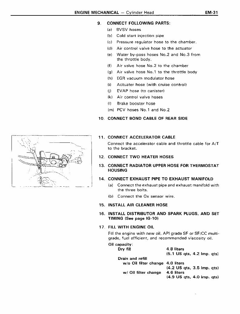
11. CONNECT ACCELERATOR CABLE
Connect the accelerator cable and throttle cable for AfTto the bracket.
12. CONNECT TWO HEATER HOSES
13. CONNECT RADIATOR UPPER HOSE FOR THERMOSTATHOUSING
14. CONNECT EXHAUST PIPE TO EXHAUST MANIFOLD
(a) Connect the exhaust pipe and exhaust manifold withthe three bolts.
(b) Connect the Ox sensor wire.
15. INSTALL AIR CLEANER HOSE
16. INSTALL DISTRIBUTOR AND SPARK PLUGS, AND SETTIMING (See page IG-10)
17. FILL WITH ENGINE OIL
Fill the engine with new oil, API grade SF or SFfCC multigrade, fuel efficient, and recommended viscosity oil.
Oil capacity:Dry fill 4.8 liters
(5.1 US qts, 4.2 Imp. qts)Drain and refill
w/o Oil filter change 4.0 liters(4.2 US qts, 3.5 Imp. qts)
w / Oil filter change 4.6 liters(4.9 US qts, 4.0 Imp. qts)

EM-32 ENGINE MECHANICAL - Cylinder Head
18. FILL WITH COOLANT
Close the radiator and engine drain cocks and fill withcoolant.
Total capacity: w/Heater 8.4 liters(8.9 US qts, 7.4 Imp. qts)
19. CONNECT CABLE TO NEGATIVE TERMINAL OF BATTERY
20. START ENGINE
Warm up the engine and inspect for leaks.
21. PERFORM ENGINE ADJUSTMENT
(a) Retighten the cylinder head bolts.(See step 3 on page EM-27)
(b) Readjust the valve clearance.(See page MA-13)
(c) Recheck ignition timing. (See step 1 on page IG-10)
(d) Adjust idle speed. (See step 14 on page MA-14)
22. RECHECK COOLANT AND ENGINE OIL LEVEL
23. ROAD TEST
Perform a road test.

ENGINE MECHANICAL - Cylinder Head EM-33
22RPREPARATION FOR REMOVAL(See page EM-12)
1. DISCONNECT CABLE FROM NEGATIVE TERMINAL OFBATTERY
2. DRAIN COOLANT FROM RADIATOR AND CYLINDERBLOCK
3. DRAIN ENGINE OIL
4. REMOVE AIR CLEANER
(a) Disconnect air hoses and air duct from the air cleaner.
(b) Remove the two nuts and wing nut.
(c) Remove the air cleaner.
5. DISCONNECT EXHAUST PIPE FROM EXHAUSTMANIFOLD
Remove three nuts holding the exhaust manifold to the exhaust pipe.
6. DISCONNECT RADIATOR UPPER HOSE FROMTHERMOSTAT HOUSING
7. DISCONNECT TWO HEATER HOSES
8. DISCONNECT ACCELERATOR CABLE FROMCARBURETOR
Disconnect the cable from the carburetor and bracket.
9. DISCONNECT FOLLOWING WIRES:
(a) VSV wire for AIC
(b) Vacuum switch wire
(c) VSV wire for EVAP
(d) Water temperature sender gauge wire
(e) Cold mixture heater wire
(f) Thermo switch wire
(g) Fuel cut solenoid valve wire
(h) EACV wire (for Calif.)
10. DISCONNECT FOLLOWING PARTS:
(a) Charcoal canister hose
(b) Brake booster hose
(c) Fuel main hose from the fuel inlet pipe
(d) Fuel return hose from the fuel return pipe
(e) HAC from the bracket (Ex. Calif.)
(f) Vacuum switch, EBCV (For Calif.) and VSV with thebracket
EM-34 ENGINE MECHANICAL - Cylinder Head
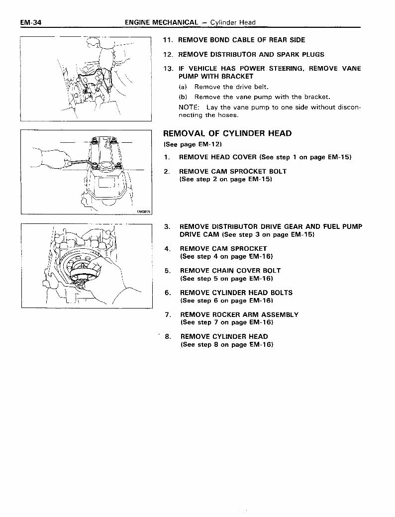
11. REMOVE BOND CABLE OF REAR SIDE
12. REMOVE DISTRIBUTOR AND SPARK PLUGS
13. IF VEHICLE HAS POWER STEERING, REMOVE VANEPUMP WITH BRACKET
(a) Remove the drive belt.
(b) Remove the vane pump with the bracket.
NOTE: Lay the vane pump to one side without disconnecting the hoses.
REMOVAL OF CYLINDER HEAD(See page EM-12)
1. REMOVE HEAD COVER (See step 1 on page EM-15)
2. REMOVE CAM SPROCKET BOLT(See step 2 on page EM-15)
EM0815
3. REMOVE DISTRIBUTOR DRIVE GEAR AND FUEL PUMPDRIVE CAM (See step 3 on page EM-15)
4. REMOVE CAM SPROCKET(See step 4 on page EM-16)
5. REMOVE CHAIN COVER BOLT(See step 5 on page EM-16)
6. REMOVE CYLINDER HEAD BOLTS(See step 6 on page EM-16)
7. REMOVE ROCKER ARM ASSEMBLY(See step 7 on page EM-16)
. 8. REMOVE CYLINDER HEAD(See step 8 on page EM-16)

ENGINE MECHANICAL - Cylinder Head EM-35
DISASSEMBLY OF CYLINDER HEAD(See page EM-12)
1. REMOVE HEAT INSULATER FROM EXHAUST MANIFOLD
2. REMOVE CHECK VALVE WITH AIR PIPE
(a) Disconnect the air pipe from the exhaust manifold.
(b) Disconnect air hose No.3 from the EACV.
(c) Remove the check valve with the air pipe.
3. REMOVE FUEL PUMP FROM CYLINDER HEAD
(a) Remove the three fuel hoses from the fuel pump.
(b) Remove the fuel pump from the cylinder head.
4. REMOVE FUEL PIPE FROM INTAKE MANIFOLD
5. REMOVE ENGINE HANGER AND AIR PIPE FROMCYLINDER HEAD
6. REMOVE EGR PIPE AND EGR VALVE WITH VACUUMMODULATOR (Ex.Calif.)
(a) Remove the vacuum hose from the air pipe.
(b) Disconnect the EGR pipe from the intake manifold.
(c) Remove the EGR valve with the EGR pipe.
7. REMOVE INTAKE MANIFOLD WITH CARBURETOR
(a) Remove the bond cable from the cylinder head.
(b) Remove the six bolts and two nuts.
(c) Remove the intake manifold with the carburetor.
8. REMOVE THERMOSTATIC VALVE
9. REMOVE EXHAUST MANIFOLD FROM CYLINDER HEAD
10. MEASURE CAMSHAFT THRUST CLEARANCE(See step 4 on page EM-17)
11. REMOVE CAM BEARING CAPS AND SHAFT(See step 5 on pagd EM-17)
12. REMOVE VALVES(See step 6 on page EM-17)
EM-36 ENGINE MECHANICAL - Cylinder Head
INSPECTION OF CYLINDER HEAD(See page EM-18)
ASSEMBLY OF CYLINDER HEAD(See page EM-12)
NOTE:
• Thoroughly clean all parts to be assembled.
• Before installing the parts, apply new engine oil to allsliding and rotating surfaces.
• Replace all gaskets and'oil seals with new parts.
1. INSTALL VALVE (See step 1 on page EM-25)
2. INSTALL CAMSHAFT (See step 2 on page EM-26)
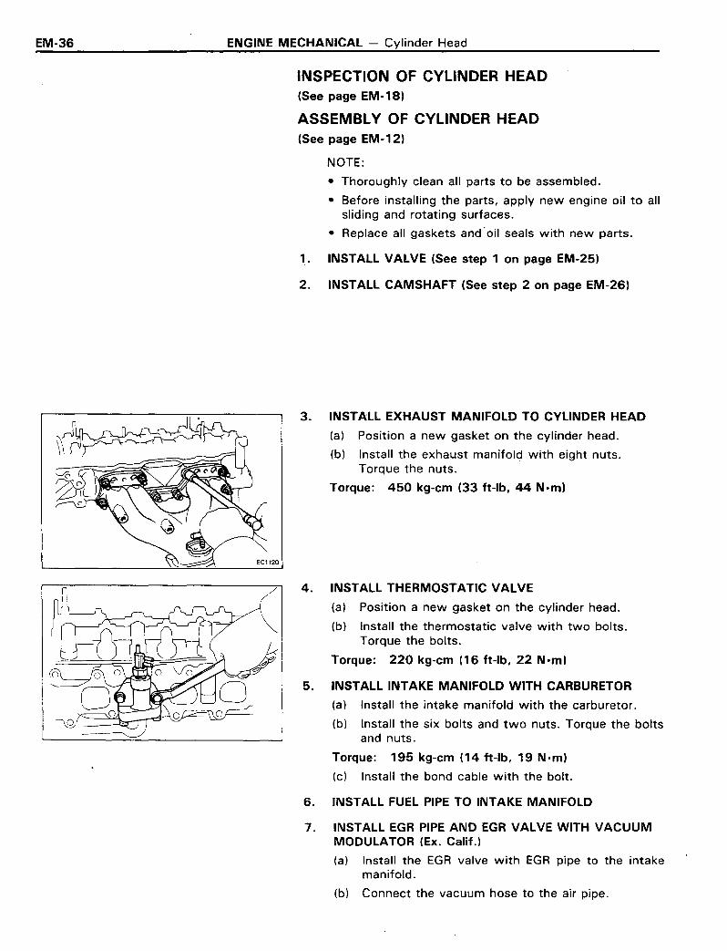
3. INSTA'LL EXHAUST MANIFOLD TO CYLINDER HEAD
(a) Position a new gasket on the cylinder head.
(b) Install the exhaust manifold with eight nuts.Torque the nuts.
Torque: 450 kg-em (33 ft-Ib, 44 N·m)
4. INSTALL THERMOSTATIC VALVE
(a) Position a new gasket on the cylinder head.
(b) Install the thermostatic valve with two bolts.Torque the bolts.
Torque: 220 kg-em (16 ft-Ib, 22 N·m)
5. INSTALL INTAKE MANIFOLD WITH CARBURETOR
(a) Install the intake manifold with the carburetor.
(b) Install the six bolts and two nuts. Torque the boltsand nuts.
Torque: 195 kg-em (14 ft-Ib, 19 N·m)
(c) Install the bond cable with the bolt.
6. INSTALL FUEL PIPE TO INTAKE MANIFOLD
7. INSTALL EGR PIPE AND EGR VALVE WITH VACUUMMODULATOR (Ex. Calif.)
(a) Install the EGR valve with EGR pipe to the intakemanifold.
(b) Connect the vacuum hose to the air pipe.

ENGINE MECHANICAL - Cylinder Head
8. INSTALL FUEL PUMP TO CYLINDER HEAD
(a) Install the fuel pump with the two bolts.Torque the bolts.
Torque: 220 kg-em (16 ft-Ib, 22 N-m)
(b) Connect the three fuel pipes.
EM-37
9. INSTALL CHECK VALVE WITH AIR PIPE
(a) Install the check valve with the air pipe.
(b) Connect air hose No.3 to the EACV.
(c) Connect the air pipe to the exhaust manifold.
10. INSTALL HEAT INSULATER TO EXHAUST MANIFOLD
INSTALLATION OF CYLINDER HEAD
1. APPLY SEALER TO CYLINDER BLOCK(See step 1 on page EM-26)
2. INSTALL CYLINDER HEAD(See step 2 on page EM-27)
3. 'NSTALL ROCKER ARM ASSEMBLY
10 4 2 5 7(See step 3 on page EM-27)
4. INSTALL CHAIN COVER BOLT(See step 4 on page EM-27)
~
5. INSTALL CAM SPROCKET ON CAMSHAFT(See step 5 on page EM-27)
8 6 3 9
6. INSTALL DISTRIBUTOR DRIVE GEAR(See step 6 on page EM-28)
7. ADJUST VALVES CLEARANCE(See step 7 on page EM-28)
EI1011r;@
8. INSTALL HEAD COVER(See step 8 on page EM-29)
EM0815

EM-38 ENGINE MECHANICAL - Cylinder Head
POST INSTALLATION
1. INSTALL VANE PUMP WITH BRACKET(WITH POWER STEERING)
Install the vane pump with the six bolts. Torque the bolts.
Torque: 450 kg-em (33 ft-Ib, 44 N am)
2. INSTALL DRIVE BELT AND ADJUST BELT TENSION(See page MA-17)
3. INSTALL DISTRIBUTOR AND SPARK PLUGS
4. INSTALL BOND CABLE OF REAR SIDE
5. CONNECT FOLLOWING PARTS:
(a) Vacuum switch, EBCV (Ex. Calif.) and VSV with thebracket
(b) HAC to bracket (Ex. Calif.)
(c) Fuel return hose to the fuel return pipe
(d) Fuel main hose to the fuel inlet pipe
(e) Brake booster hose
(f) Charcoal canister hose
6. CONNECT FOLLOWING WIRES:
(a) EACV wire (for Calif.)
(b) Fuel cut solenoid valve wire
(c) Thermo switch wire
(d) Cold mixture heater wire
(e) Water temperature sender gauge wire
(f) VSV wire for EVAP
(g) Vacuum switch wire
(h) VSV wire for AIC
7. CONNECT ACCELERATOR CABLE TO CARBURETOR
Connect the cable to the carburetor and bracket.
8. CONNECT TWO HEATER HOSES
9. CONNECT RADIATOR UPPER HOSE TO THERMOSTATHOUSING
10. CONNECT EXHAUST PIPE TO EXHAUST MANIFOLD
Connect the exhaust pipe with the three nuts to the exhaust manifold.

ENGINE MECHANICAL - Cylinder Head
11 . INSTALL AIR CLEANER
(a) Install the air cleaner on the carburetor.
(b) Connect the air hoses and air duct.
EM-39
12. FILL WITH ENGINE OIL
Fill the engine with new oil, AP\ grade Sr: or Sr:1CC mu\t\grade, fuel efficient and recommended viscosity oil.
Capacity:Dry fill 4.8 liters
(5.1 US qts, 4.2 Imp. qts)Drain and refill
wlo Oil filter change 4.0 liters(4.2 US qts, 3.5 Imp. qts)
wI Oil filter change 4.6 liters(4.9 US qts, 4.0 Imp. qts)
13. FILL WITH COOLANT
Close the radiator and engine drain cocks and fill withcoolant.
Total capacity: w/Heater 8.4 liters(8.9 US qts, 7.4 Imp. qts)
14. CONNECT CABLE TO NEGATIVE TERMINAL OF BATTERY
15. START ENGINE
Warm up the engine and inspect for leaks.
16. PERFORM ENGINE ADJUSTMENT
(a) Retighten the cylinder head bolts.(See step 3 on page EM-27)
(b) Readjust the valve clearance.(See page MA-13)
(c) Recheck ignition timing. (See step 1 on page IG-10)
(d) Adjust idle speed. (See step 14 on page MA-14)
17. RECHECK COOLANT AND ENGINE OIL LEVEL
18. ROAD TEST
Perform a road test.
EM-40 ENGINE MECHANICAL - Timing Chain
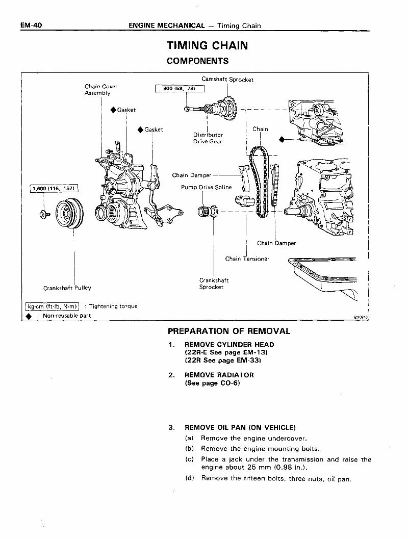
TIMING CHAINCOMPONENTS
Chain Damper
-,- - - - --III ChainIIJ
Chain Tensioner
Camshaft Sprocket
DistributorDrive Gear
CrankshaftSprocket
EM0816
+ Gasket
+Gasket
Chain CoverAssembly
1,600 (116, 157)
Crankshaft Pulley
Ikg-cm (ft-Ib, N·m) I : Tightening torque
• : Non-reusable part
PREPARATION OF REMOVAL
1. REMOVE CYLINDER HEAD(22R-E See page EM-13)(22R See page EM-33)
2. REMOVE RADIATOR(See page CO-6)
3. REMOVE OIL PAN (ON VEHICLE)
(a) Remove the engine undercover.
(b) Remove the engine mounting bolts.
(c) Place a jack under the transmission and raise theengine about 25 mm (0.98 in.).
(d) Remove the fifteen bolts, three nuts, oil pan.
ENGINE MECHANICAL - Timing Chain
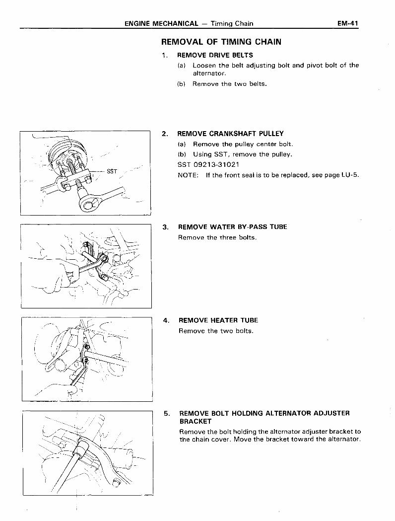
REMOVAL OF TIMING CHAIN
EM-41
1 . REMOVE DRIVE BELTS
(a) Loosen the belt adjusting bolt and pivot bolt of thealternator.
(b) Remove the two belts.
2. REMOVE CRANKSHAFT PULLEY
(a) Remove the pulley center bolt.
(b) Using SST, remove the pulley.
SST 09213-31021
NOTE: If the front seal is to be replaced, see page LU-5.
3. REMOVE WATER BY-PASS TUBE
Remove the three bolts.
/'
/~~/.~ /
I
'/
4. REMOVE HEATER TUBE
Remove the two bolts.
5. REMOVE BOLT HOLDING ALTERNATOR ADJUSTERBRACKET
Remove the bolt holding the alternator adjuster bracket tothe chain cover. Move the bracket toward the alternator.

EM-42 ENGINE MECHANICAL - Timing Chain
6. REMOVE CHAIN COVER ASSEMBLY
(a) Remove six timing chain cover bolts shown by tpoarrows.
(b) Using a plastic faced hammer, loosen the chain coverand remove it.
7. REMOVE CHAIN AND CAMSHAFT SPROCKET
(a) Remove the chain from the damper.
(b) Remove the cam sprocket and chain together.
8. REMOVE PUMP DRIVE SPLINE AND CRANKSHAFTSPROCKET
,-----' If the pump drive and sprocket cannot be removed by hand,use SST to remove them together.
SST 09213-36020
9. REMOVE GASKET MATERIAL ON CYLINDER BLOCK
ENGINE MECHANICAL - Timing Chain
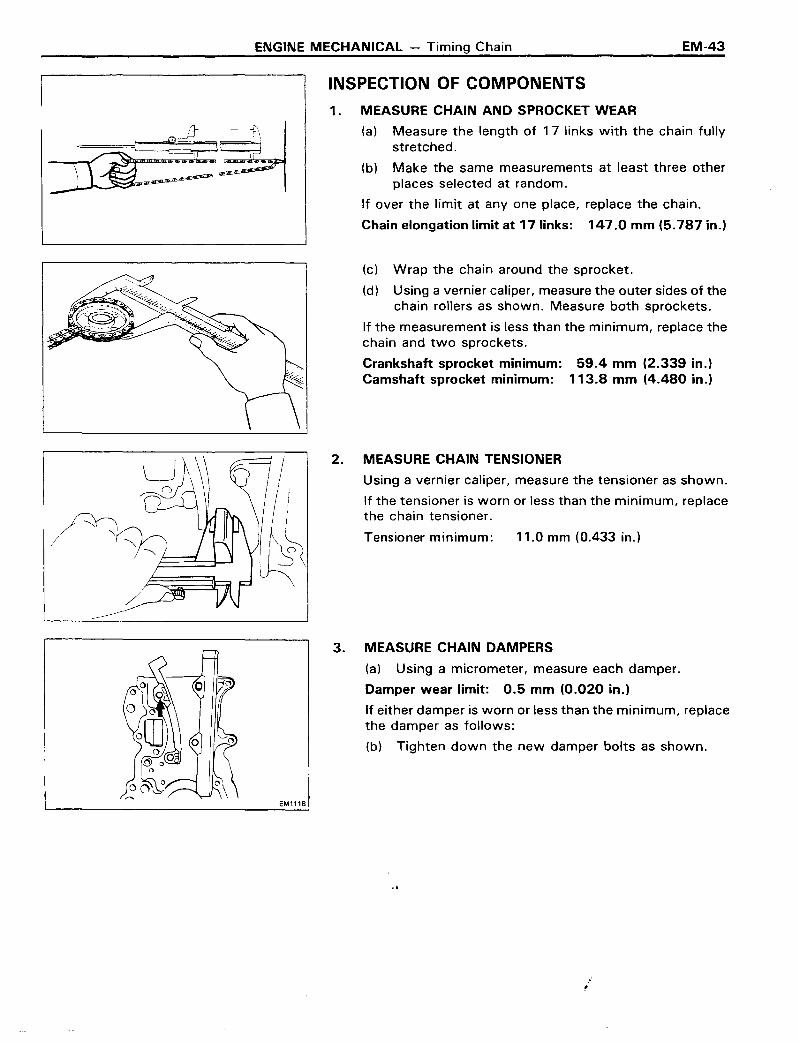
INSPECTION OF COMPONENTS
EM-43
~~1\~ ..... c=:rd•• • • 10.
IO·· ...
1. MEASURE CHAIN AND SPROCKET WEAR
(a) Measure the length of 17 links with the chain fullystretched.
(b) Make the same measurements at least three otherplaces selected at random.
If over the limit at anyone place, replace the chain.
Chain elongation limit at 17 links: 147.0 mm (5.787 in.)
(c) Wrap the chain around the sprocket.
(d) Using a vernier caliper, measure the outer sides of thechain rollers as shown. Measure both sprockets.
If the measurement is less than the minimum, replace thechain and two sprockets.
Crankshaft sprocket minimum: 59.4 mm (2.339 in.)Camshaft sprocket minimum: 113.8 mm (4.480 in.)
2. MEASURE CHAIN TENSIONER
Using a vernier caliper, measure the tensioner as shown.
If the tensioner is worn or less than the minimum, replacethe chain tensioner.
I
~ Tensioner minimum: 11.0 mm (0.433 in.)
EM1118
3. MEASURE CHAIN DAMPERS
(a) Using a micrometer, measure each damper.
Damper wear limit: 0.5 mm (0.020 in.)
If either damper is worn or less than the minimum, replacethe damper as follows:
(b) Tighten down the new damper bolts as shown.
.t
..i

EM-44 ENGINE MECHANICAL - Timing Chaing, '~: '1
INSTALLATION OF TIMIN(Seepage EM-40);:~,:L
"1' ,,',,' .
1. INSTALL CRANKSHAFT SPRO~;"ANDCHAIN
(a) Turn the crankshaft until the shaft key is on top.
(b) Slide the sprocket over the key on the crankshaft.
(c) Place the timing chain on the sprocket with the singlebright link aligned with the timing mark on thesprocket.
2. PLACE CHAIN ON CAMSHAFT SPROCKET .
(a) Place the timing chain on the sprocket so that the timing mark is bright chain links.
(b) Make sure the chain is positioned between the twodampers. .
(c) Turn the camshaft sprocket counterclockwise to takethe slack out of the chain:
EMll19
3. INSTALL OIL PUMP DRIVE SPLINE
Slide the oil pump drive spline over the crankshaft key .
•
4. INSTALL TIMING- CHAIN COVER ASSEMBLY
(a) Remove the old cover gaskets .. Clean the gasket surface. Install new gaskets over the dowels ..
(b) Slide the cover assembly over the dowels and pumpspline.
(c) Insert the bolts as shQwn and torque them.
Torque:8 Film bolt .130 kg-~ (9.ft-lb, 13 Nom)10 mm bolt 400 kg-em (29 ft-Ib, 39 Nom)
5. INSTALL BOLT HOLDING ALTERNATOR ADJUSTER8RACKET
Install the bolt holding the alterllator adjuster bracket tothe chain cover.
Torque the bolt.
Torque: 130 kg-ern (9 ft-Ib, 13"N om)

ENGINE MECHANICAL - Timing Chain EM-45
6. INSTALL WATER BY-PASS TUBE TO CHAIN COVER
Install the three bolts.
7. INSTALL HEATER TUBE TO CHAIN COVER
Install the two bolts.
8. INSTALL CRANKSHAFT ~"",~~, . ;i:~",.j(a) Install the pulley over the' crankshaft ke'tl~~~!Y~~'i:
CAUTIeN: Do not turn the crankshaft.
(b) Torque the pulley center bolt.
Torque: 1,600 kg-em f116 ft-Ib, 157 Nom)
•
•
9. INSTALL ~IVE BELTS'i't',
Using a belt tens~n gauge, check the drive belt tension.
Belt tensttn gauge:
Nippondenso BTG-20 (95506-00020) orBorroughs No. BT-33-73F,,'.
• Drive belt tension: New belt 125 ± 25 IbUsed belt 80 ± 20 Ib
•
.:: .

EM-46 ENGINE MECHANICAL - Timing Chain
Inside of hole
Seal width approx.5 mm (0.20 in.)
10. INSTALL OIL PAN
(a) Remove any old packing material and be careful 1"'1
to drop any oil on the contacting surfaces of thepan and cylinder block.
• Using a razor blade and gasket scraper, remove allthe packing (FIPG) material from the gasket surfaces.
• Thoroughly clean all components to remove all theloose material.
• Clean both sealing surfaces with a non-residuesolvent.
CAUTION: Do not use a solvent which will affect thepainted surfaces.
(b) Apply liquid sealer to the joint part of the cylinder blockand chain cover, cylinder block and rear oil seal retainer.
(c) Apply No.1 02 seal packing (Part No. 08826-00080or equivalent to the oil pan as shown in the figure.
• Install a nozzle that has been cut to a 5-mm (0.20in.) opening.
NOTE: Avoid applying an excess amount to the surface.Be especially careful near oil passages.
• Parts must be assembled within 5 minutes of ap-~.. plication. Otherwise, the material must be removed
and re-applied.
• Immediately remove nozzle from tube and reinstallcap.
(d) Install the oil pan over the studs on the block with sixteen bolts and two nuts. Torque the bolts and nuts.
Torque: 130 kg-em (9 ft-Ib, 13 Nom)
(e) Lower the engine and install the engine mountingbolts.
!
LJEM0845
,T7tJ 5 mm (0.20 in.)EM0847LU0099
r~Groove
(f) Intall the engine under cover.
POST INSTALLATI·ON
11. INSTALL RADIATOR (See page CO-12)
12. INSTALL CYLINDER HEAD(22R-E See page EM-25)(22R See page EM-36)

ENGINE MECHANICAL - Cylinder Block
22R-ECYLINDER BLOCKPREPARATION FOR REMOVAL
EM-47
1. DISCONNECT CABLE FROM NEGATIVE TERMINAL OFBATTERY
2. REMOVE ENGINE UNDER COVER
3. REMOVE ENGINE HOOD
Disconnect the washer hose from the hood.
4. DRAIN COOLANT FROM RADIATOR AND CYLINDERBLOCK
5. DRAIN AUTOMATIC TRANSMISSION FLUID(with AfT)
6.
7.
REMOVE AIR CLEANER HOSE AND AIR CLEANER
REMOVE COUPLING FAN WITH FAN
•
8. REMOVE TWO HEATER HOSES
9. REMOVE RADIATOR WITH SHROUD
(a) Disconnect the two cooler hoses. (with AfT)
(b) Disconnect the radiator upper and lower hoses fromthe engine.
(c) Disconnect the reservoir hose.
(d). Remove the radiator with the shroud.
10. DISCONNECT CABLES FROM BRACKET
Disconnect the accelerator cable and throttle cable for AfTfrom the bracket.
11. DISCONNECT FOLLOWING PARTS:
(a) PCV hose No.1 and No.2
(b) Brake booster hose
(c) Air control valve hoses
(d) EVAP hose (from canister)
(e) Actuater hose (with cruise control)
(f) EGR vacuum modulator hose
(g) Air valve hose No.1 from the throttle body
(h) Air valve hose No.2 from the chamber
0) Water by-pass hose No.2 and No.3 from the throttlebody
(j) Air control valve hose for the actuator
(k) Pressure regulator hose from the chamber
(I) Cold start injection pipe
(m) BVSV hoses
EM-48 ENGINE MECHANICAL - Cylinder Block
12. DISCONNECT FOLLOWING WIRES:
(a) Cold start injection wire
(b) Throttle position sensor wire
(c) Air valve wire
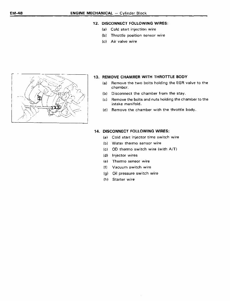
13. REMOVE CHAMBER WITH THROTTLE BODY
(a) Remove the two bolts holding the EGR valve to thechamber.
(b) Disconnect the chamber from the stay.
(c) Remove the bolts and nuts holding the chamber to theintake manifold.
(d) Remove the chamber with the throttle body.
14. DISCONNECT FOLLOWING WIRES:
(a) Cold start injector time switch wire
(b) Water thermo sensor wire
(c) 00 thermo switch wire (with AfT)
(d) Injector wires
(e) Thermo sensor wire
(f) Vacuum switch wire
(9) Oil pressure switch wire
(h) Starter wire
ENGINE MECHANICAL - Cylinder Block
REMOVAL OF CYLINDER BLOCK
1. DISCONNECT FOLLOWING PARTS:
(a) Alternator wires
(b) High-tension cord for ignition coil
(c) Distributor wire from igniter
(d) Ox sensor wire
EM-49
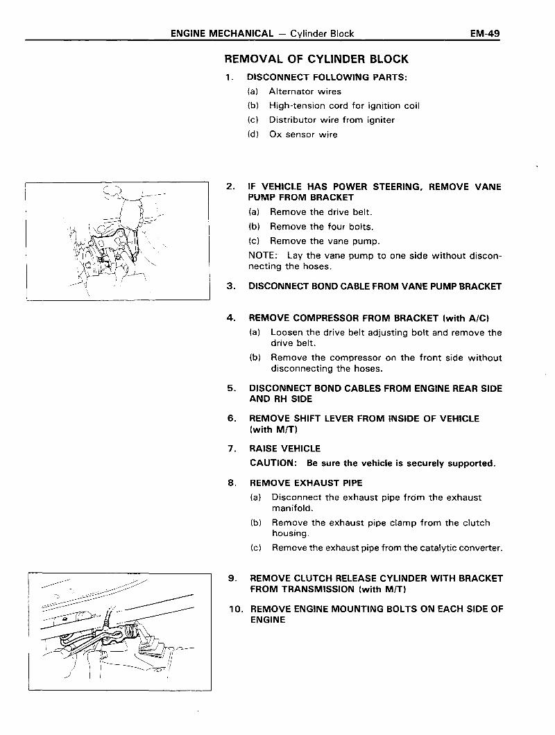
2. IF VEHICLE HAS POWER STEERING. REMOVE VANEPUMP FROM BRACKET
(a) Remove the drive belt.
(b) Remove the four bolts.
(c) Remove the vane pump.
NOTE: Lay the vane pump to one side without disconnecting the hoses.
3. DISCONNECT BOND CABLE FROM VANE PUMP BRACKET
4. REMOVE COMPRESSOR FROM BRACKET (with A/C)
(a) Loosen the drive belt adjusting bolt and remove thedrive belt.
(b) Remove the compressor on the front side withoutdisconnecting the hoses.
5. DISCONNECT BOND CABLES FROM ENGINE REAR SIDEAND RH SIDE
6. REMOVE SHIFT LEVER FROM INSIDE OF VEHICLE(with MIT)
7. RAISE VEHICLE
CAUTION: Be sure the vehicle is securely supported.
8. REMOVE EXHAUST PIPE
(a) Disconnect the exhaust pipe from the exhaustmanifold.
(b) Remove the exhaust pipe clamp from the clutchhousing.
(c) Remove the exhaust pipe from the catalytic converter.
9. REMOVE CLUTCH RELEASE CYLINDER WITH BRACKETFROM TRANSMISSION (with MIT)
10. REMOVE ENGINE MOUNTING BOLTS ON EACH SIDE OFENGINE

EM-50 ENGINE MECHANICAL - Cylinder Block
11. DISCONNECT FOLLOWING PARTS:
(a) Oil pressure sender gauge wire
(b) Neutral start switch wire (with AfT)
(c) Back-up light switch wire
(d) Fuel hose
~---------
12. REMOVE INTERMEDIATE SHAFT
(a) Put alignment marks on the flanges.
(b) Remove the four bolts and nuts.
(c) Remove the two bolts holding the center support bear-ing to the body.
(d) Pull the sleeve yoke from the transmission.
(e) Insert SST in the transmission to prevent oil leakage.
SST 09325-20010
13. DISCONNECT SHIFT LINKAGE FROM SHIFT LEVER(with AfT)
14. DISCONNECT SPEEDOMETER CABLE
CAUTION: Do not lose the felt dust protector andwashers.
15. PLACE JACK UNDER TRANSMISSION
Be sure to put a wooden block between the jack and thetransmission pan.
16. REMOVE ENGINE REAR MOUNTING BRACKET
(a) Remove the four bolts holding the bracket to themember.
(b) Remove the four bolts holding the bracket to thetransmission and remove the bracket.
17. REMOVE ENGINE WITH TRANSMISSION FROM VEHICLE
(a) Attach the engine hoist chain to the lift brackets ofthe engine.
(b) Lift the engine out of the vehicle slowly and careful/y.
NOTE: Make sure the engine is clear of all wiring andhoses.
18. REMOVE TRANSMISSION FROM ENGINE
(a) Remove the starter.
(b) Remove the two stiffener plates and exhaust pipebracket from engine.
(c) Remove the transmission from the engine.
ENGINE MECHANICAL - Cylinder Block
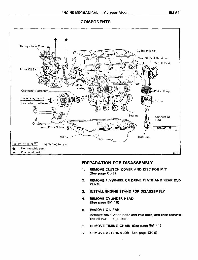
COMPONENTS
~(I)~~RodBearing
Rod Cap
I kg-cm (ft-Ib, N.mll : Tightening torque
• Non-reusable part* :Precoated part
EM-51
ConnectingRod
630 (46, 62)
EMoala
PREPARATION FOR DISASSEMBLY
1. REMOVE CLUTCH COVER AND DISC FOR MIT(See page CL-7)
2. REMOVE FLYWHEEL OR DRIVE PLATE AND REAR ENDPLATE
3. INSTALL ENGINE STAND FOR DISASSEMBLY
4. REMOVE CYLINDER HEAD(See page EM-15)
5. REMOVE OIL PAN
Remove the sixteen bolts and two nuts, and then removethe oil pan and gasket.
6. REMOVE TIMING CHAIN (See page EM-41)
7. REMOVE ALTERNATOR (See page CH-6)

EM-52 ENGINE MECHANICAL - Cylinder Block
DISASSEMBLY OF CYLINDER BLOCK
1. REMOVE OIL STRAINER
Remove the four bolts holding the oil strainer.
2. REMOVE REAR OIL SEAL RETAINER
Remove the five bolts, rear oil seal retainer and gasket.
3. MEASURE CONNECTING ROD THRUST CLEARANCE
Using a feeler gauge, measure the rod thrust clearance.
If clearance is greater than the maximum, replace the connecting rod.
Rod thrust maximum clearance: 0.30 mm (0.0118 in.)
4. REMOVE CONNECTING ROD CAPS AND MEASURE OILCLEARANCE
(a) Using a punch or numbering stamp, mark the connecting rods and caps to ensure correct reassemb'
(b) Remove the rod caps.
Remove the rod cap nuts. Using a plastic hammer, tapthe rod bolts lightly and lift off the rod caps. Keep thebearing inserted with the cap.
(c) Clean the bearings and crankshaft pins.
(d) Inspect each bearing for pitting and radial scratches.
If bearings are damaged, replace them.
(e) Lay a strip of Plastigage across the crankshaft pin.
ENGINE MECHANICAL - Cylinder Block EM-53
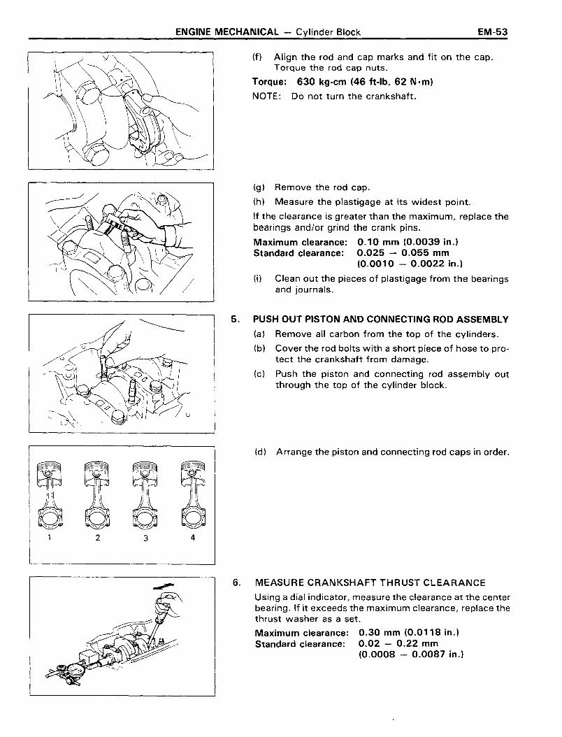
(f) Align the rod and cap marks and fit on the cap.Torque the rod cap nuts.
Torque: 630 kg-cm (46 ft-Ib, 62 Nom)
NOTE: Do not turn the crankshaft.
(g) Remove the rod cap.
(h) Measure the plastigage at its widest point.
If the clearance is greater than the maximum, replace thebearings and/or grind the crank pins.
Maximum clearance: 0.10 mm (0.0039 in.)Standard clearance: 0.025 - 0.055 mm
(0.0010 - 0.0022 in.)
(j) Clean out the pieces of plastigage from the bearingsand journals.
5. PUSH OUT PISTON AND CONNECTING ROD ASSEMBLY
(a) Remove all carbon from the top of the cylinders.
(b) Cover the rod bolts with a short piece of hose to protect the crankshaft from damage.
(c) Push the piston and connecting rod assembly outthrough the top of the cylinder block.
(d) Arrange the piston and connecting rod caps in order.
2 3 4
6. MEASURE CRANKSHAFT THRUST CLEARANCE
Using a dial indicator, measure the clearance at the centerbearing. If it exceeds the maximum clearance, replace thethrust washer as a set.
Maximum clearance: 0.30 mm (0.0118 in.)Standard clearance: 0.02 - 0.22 mm
(0.0008 - 0.0087 in.)

EM-54 ENGINE MECHANICAL - Cylinder Block
7. REMOVE MAIN BEARING CAPS AND MEASURE OILCLEARANCE
(a) Remove the main bearing caps by removing two be
(b) Lift out the crankshaft and remove the upper mainbearings from the cylinder block.
(c) Clean the bearing and main journals.
Inspect each bearing for pitting and radial scratches.
If bearings are damaged, replace them.
(d) Install the upper main bearings on the cylinder blockand crankshaft.
(e) Lay a strip of plastigage across the main journals.
(f) Install the main bearing caps. Torque the cap bolts.
Torque: 1,050 kg-cm (76 ft-Ib, 103 N em)
NOTE: Do not turn the crankshaft.
(g) Remove the main bearing caps.
(h) Measure the plastigage at its widest point.
If the clearance is greater than the maximum, replace thebearings and/or grind the main journals.
Maximum clearance: 0.08 mm (0.0031 in.)Standard clearance: 0.025 - 0.055 mm
(0.0010 - 0.0022 in.)
(i) Clean out the pieces of plastigage from the bearingsand journals.
8. REMOVE CRANKSHAFT
(a) Lift out the crankshaft.
(b) Remove the upper main bearings from the cylinderblock.
(c) Arrange the caps and bearings in order.
ENGINE MECHANICAL - Cylinder Block
INSPECTION OF CYLINDER BLOCK
EM-55
o
1. REMOVE GASKET MATERIAL
Using a gasket scraper, remove all gasket material fromcylinder block surfaces.
2. CLEAN CYLINDER BLOCK
Using a soft brush and solvent, clean the block.
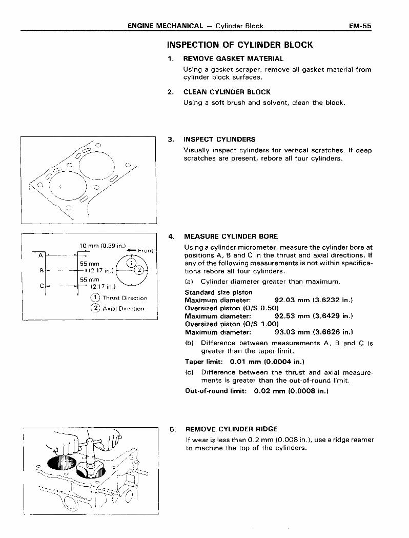
3. INSPECT CYLINDERS
Visually inspect cylinders for vertical scratches. If deepscratches are present, rebore all four cylinders.
A
B
c
10 mm (0.39 in.).- Front
55mm ~1(2.17 in.) . (1)
55mm I
---lr---'- (2.17 in.)
CD Thrust Direction
@ Axial Direction
4. MEASURE CYLINDER BORE
Using a cylinder micrometer, measure the cylinder bore atpositions A, Band C in the thrust and axial directions. Ifany of the following measurements is not within specifications rebore all four cylinders.
(a) Cylinder diameter greater than maximum.
Standard size pistonMaximum diameter: 92.03 mm (3.6232 in.)Oversized piston (OIS 0.50)Maximum diameter: 92.53 mm (3.6429 in.)Oversized piston (0/5 1.00)Maximum diameter: 93.03 mm (3.6626 in.)
(b) Difference between measurements A, Band C isgreater than the taper limit.
Taper limit: 0.01 mm (0.0004 in.)
(c) Difference between the thrust and axial measurements is greater than the out-of-round limit.
Out-of-round limit: 0.02 mm (0.0008 in.)
5. REMOVE CYLINDER RIDGE
If wear is less than 0.2 mm (0.008 in.), use a ridge reamerto machine the top of the cylinders.
EM-56 ENGINE MECHANICAL - Cylinder Block
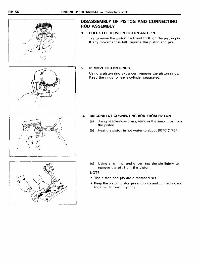
DISASSEMBLY OF PISTON AND CONNECTINGROD ASSEMBLY
1. CHECK FIT BETWEEN PISTON AND PIN
Try to move the piston back and forth on the piston pin.If any movement is felt, replace the piston and pin.
\.-
2. REMOVE PISTON RINGS
Using a piston ring expander, remove the piston rings.Keep the rings for each cylinder separated.
3. DISCONNECT CONNECTING ROD FROM PISTON
(a) Using needle-nose pliers, remove the snap rings fromthe piston.
(b) Heat the piston in hot water to about 80°C (176°l
(c) Using a hammer and driver, tap the pin lightly toremove the pin from the piston.
NOTE:
• The piston and pin are a matched set.
• Keep the piston, piston pin and rings and connecting rodtogether for each cylinder.

ENGINE MECHANICAL - Cylinder Block EM-57
INSPECTION OF PISTON AND CONNECTING RODASSEMBLY
1. CLEAN PISTON
(a) Scrape off carbon from the piston top.
(b) Using a groove cleaning tool or broken ring, clean thering grooves.
(c) Using solvent and a brush,c1ean the piston thoroughly.
CAUTION: Do not use a wire brush.
2. MEASURE PISTON DIAMETER
(a) Using a micrometer, measure the piston diameter asshown.
Standard diameter: 91.960 - 91.990 mm(3.6205 - 3.6216 in.)
(b) Check that the difference between the cylinder dia-meter and the piston diameter is within specification.
If not within specification, replace the piston and/or reborethe cylinder.
Piston clearance: 0.02 - 0.04 mm(0.0008 - 0.0016 in.)
0.24-0.39 mm (0.009-0.015 in.)0.18-0.42 mm (0.007-0.017 in.)0.20-0.82 mm (0.008-0.032 in.)0.99 mm (0.039 in.)1.02 mm (0.040 in.)1.42 mm (0.056 in.)
, ,
'dI I, 'I ', 1 •
: I :
1
II II ,I ,
3. MEASURE CLEARANCE BETWEEN PISTON GROOVEAND PISTON RING
Using a feeler gauge, measure the clearance between thepiston ring and the ring land.
If the clearance is greater than the maximum, replace thepiston.
Maximum clearance between compression ring No.1 or 2and ring land: 0.2 mm (0.008 in.)
4. MEASURE RING END GAP
Measure the ring end gap.
(a) Insert the piston ring into the cylinder.
(b) Using a piston, push the ring to the bottom of the ringtravel.
(c) Using a feeler gauge, measure the end gap.
If not within specification, replace the ring. Do not file thering end.
Ring end gap:Standard No.1
No.2Oil
Maximum No.1No.2Oil
EM-58 ENGINE MECHANICAL - Cylinder Block
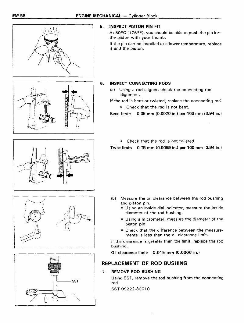
5. INSPECT PISTON PIN FIT
At 80°C (176°F), you should be able to push the pin in+~
the piston with your thumb.
If the pin can be installed at a lower temperature, replaceit and the piston.
6. INSPECT CONNECTING RODS
(a) Using a rod aligner, check the connecting rodalignment.
If the rod is bent or twisted, replace the connecting rod.
• Check that the rod is not bent.
Bend limit: 0.05 mm (0.0020 in.) per 100 mm (3.94 in.)
• Check that the rod is not twisted.
Twist limit: 0.15 mm (0.0059 in.) per 100 mm (3.94 in.)
(b) Measure the oil clearance between the rod bushingand piston pin.• Using an inside dial indicator, measure the inside
diameter of the rod bushing.
• Using a micrometer, measure the diameter of thepiston pin.
• Check that the difference between the measure-ments is less than the oil clearance limit.
If the clearance is greater than the limit, replace the rodbushing.
Oil clearance limit: 0.015 mm (0.0006 in.)
REPLACEMENT OF ROD BUSHING
1 . REMOVE ROD BUSHING
Using SST, remove the rod bushing from the connectingrod.
SST 09222-30010
ENGINE MECHANICAL - Cylinder Block EM-59
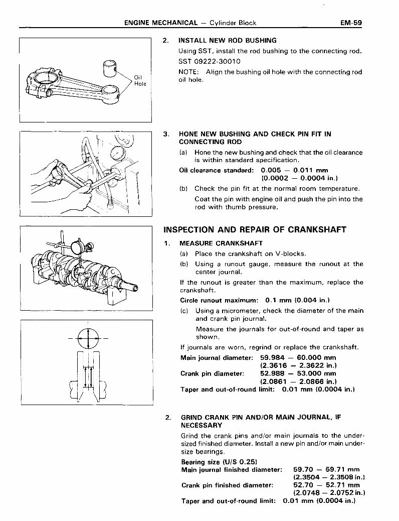
OilHole
2. INSTALL NEW ROD BUSHING
Using SST, install the rod bushing to the connecting rod.
SST 09222-30010
NOTE: Align the bushing oil hole with the connecting rodoil hole.
3. HONE NEW BUSHING AND CHECK PIN FIT INCONNECTING ROD
(a) Hone the new bushing and check that the oil clearanceis within standard specification.
Oil clearance standard: 0.005 - 0.011 mm(0.0002 - 0.0004 in.)
(b) Check the pin fit at the normal room temperature.
Coat the pin with engine oil and push the pin into therod with thumb pressure.
-$-
INSPECTION AND REPAIR OF CRANKSHAFT
1. MEASURE CRANKSHAFT
(a) Place the crankshaft on V -blocks.
(b) Using a runout gauge, measure the runout at thecenter journal.
If the runout is greater than the maximum, replace thecrankshaft.
Circle runout maximum: 0.1 mm (0.004 in.)
(c) Using a micrometer, check the diameter of the mainand crank pin journal.
Measure the journals for out-of-round and taper asshown.
If journals are worn, regrind or replace the crankshaft.
Main journal diameter: 59.984 - 60.000 mm(2.3616 - 2.3622 in.)
Crank pin diameter: 52.988 - 53.000 mm(2.0861 - 2.0866 in.)
Taper and out-of-round limit: 0.01 mm (0.0004 in.)
2. GRIND CRANK PIN AND/OR MAIN JOURNAL, IFNECESSARY
59.70 - 59.71 mm(2.3504 - 2.3508 in.)52.70 - 52.71 mm(2.0748 - 2.0752 in.)
0.01 mm (0.0004 in.)
Crank pin finished diameter:
Taper and out-of-round limit:
Grind the crank pins and/or main journals to the undersized finished diameter. Install a new pin and/or main undersize bearings.
Bearing size (U/S 0.25)Main journal finished diameter:

EM-60 ENGINE MECHANICAL - Cylinder Block
SizeOutside Diametermm (in.)
92.460 - 92.490O/S 0.50 (3.6402 - 3.6413)
O/S 1.0092.960 - 92.990(3.6598 - 3.6610)
REPLACEMENT OF REAR OIL SEAL
1. REMOVE OIL SEAL FROM OIL SEAL RETAINER
Using a screwdriver, remove the oil seal.
2. INSTALL NEW OIL SEAL ON OIL SEAL RETAINER
(a) Using SST, install a new oil seal.
SST 09223-41020
(b) Coat the seal lightly with multipurpose grease.
BORING OF CYLINDERS
1. SELECT OVERSIZED PISTON
O/S pistons with pins are available in the sizes listed.Replace pistons in matched sets. Take the largest boomeasured and select the oversized piston for that bore.Bore all cylinders for the oversized piston selected.
2. CALCULATE DIMENSION TO BORE CYLINDERS
(a) Using a micrometer, measure the piston diameter asshown.
(b) Calculate the size each cylinder is to be rebored asfollows:
Size to be rebored =. P + C - HP = piston diameterC = piston clearance
0.02 - 0.04 mm (0.0008 - 0.0016 in.)
H = allowance for honing
Less than 0.02 mm (0.0008 in.)
3. BORE AND HONE CYLINDERS TO CALCULATEDDIMENSIONS
Honing amount: 0.02 mm (0.0008 in.) maximum
CAUTION: Excess honing will destroy the finishedroundness.

ENGINE MECHANICAL - Cylinder Block EM-61
GENERAL ASSEMBLY NOTE:
Thoroughly clean all parts to be assembled. Before installingparts, app\y new eng\ne 0\\ to a\\ s\\d\ng and TQtat\ng SUftdC.~b.
Mark ----+-<
Compression Oil RingRing No.1 and /-_~~==:-..... Lower Side RailExpander I';V- ..... --.><\
"/ \ \I f \ \
Front. ',' " :
, \ I "\ \ I I
'0 <;(:- _-- ---~Oil Ring - --- Compression
Upper Side Rail Ring No.2
ASSEMBLY OF PISTON AND CONNECTINGROD ASSEMBLY
1. ASSEMBLY PISTON AND CONNECTING ROD
(a) Install a new snap ring on one side of the piston pinhole.
(b) Heat the piston in hot water to about 80 0 C (176°F).
(c) Align the notch on the piston with the mark on therod and push the piston pin in with your thumb.
(d) Install a new snap ring on the other side of the pin.
2. PLACE RINGS ON PISTON
(a) Using a ring expander, install the top two compression rings with the code marks facing upward.
(b) Position the piston rings so that the ring end gaps arein the shaded area as shown.
CAUTION: Do not align the end gaps.
3. INSTAll BEARING INSERTS
(a) Install the bearing inserts in the connecting rods androd caps.
(b) Lubricate the face of the bearings with engine oil.

EM-52 ENGINE MECHANICAL - Cylinder Block
INSTALLATION OF CRANKSHAFT, PISTON ANDCONNECTING ROD ASSEMBLY
1. INSTALL UPPER MAIN BEARING IN CYLINDER BLOCo,,"
(a) Place the upper main bearing in the block.
(b) Install the upper thrust washers on the center mainbearing with the oil grooves facing outward.
(c) Lubricate the faces of the bearings with engine oil.
SizeI
Thickness mm (in.)
i
STD I 2.00 (0.0787)!
0/SO.125 I 2.06 (0.0811 )I
OIS 0.250
I2.13 (0.0839)
2. PLACE CRANKSHAFT IN CYLINDER BLOCK
3. INSTALL MAIN BEARING CAPS
NOTE: Each bearing cap is numbered.
(a) Install thrust washers on bearing cap No.3 with theoil grooves facing out ward.
(b) Install the bearing caps in numbered order with thearrows facing forward. Tighten the bolts to thespecified torque in the sequence shown in two or threepasses.
Torque: 1,050 kg-cm (76 ft-Ib, 103 Nom)
(c) Measure the crankshaft thrust. (See step 6 on pageEM-53)
Using a feeler gauge, measure the clearance at thecenter bearing.
If the clearance is greater than the maximum, replacethe thrust washer.
Maximum clearance: 0.30 mm (0.0118 in.)
Select a thrust washer to obtain the standard clearance.
Standard clearance: 0.02 - 0.22 mm(0.0008 - 0.0087 in.)
(d) Check that the crankshaft turns.
4. INSTALL PISTON AND CONNECTING ROD ASSEMBLY
(a) Lubricate the cylinder bore and rod journal with cleanengine oil.
(b) Using a ring compressor, push the correctly numberedpiston and rod assembly into each cylinder. Make surethe notch and mark are facing forward.
ENGINE MECHANICAL - Cylinder Block EM-63
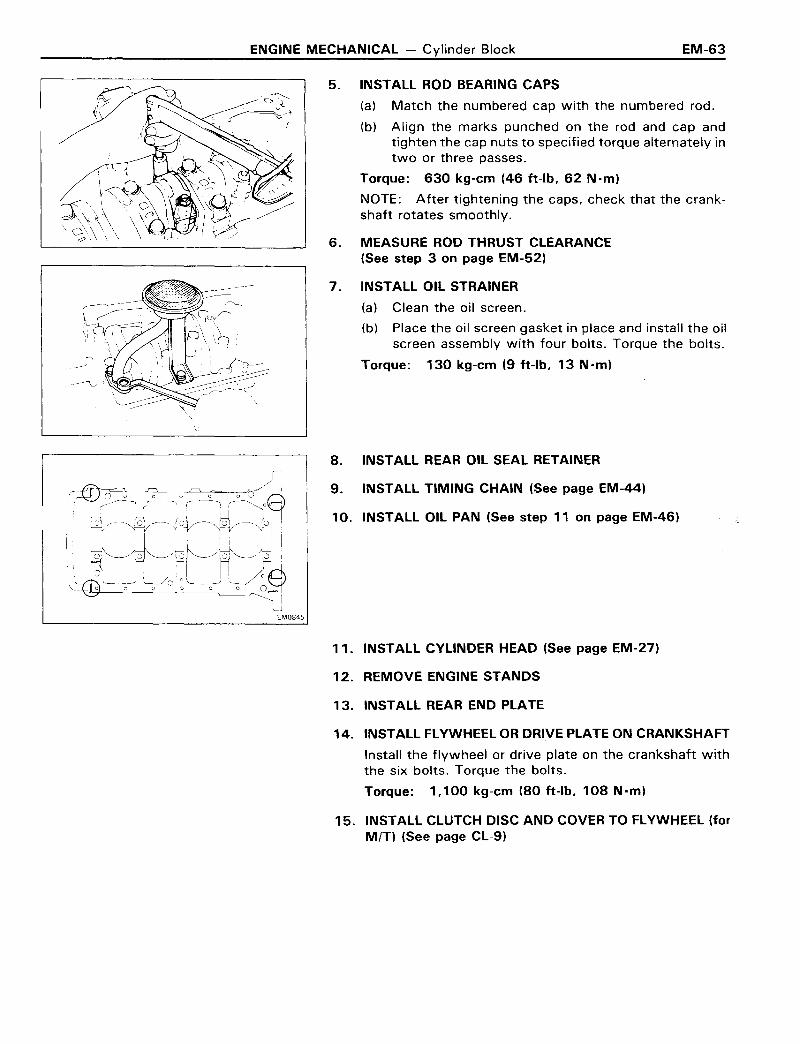
5. INSTALL ROD BEARING CAPS
(a) Match the numbered cap with the numbered rod.
(b) Align the marks punched on the rod and cap andtighten the cap nuts to specified torque alternately intwo or three passes.
Torque: 630 kg-em (46 ft-Ib, 62 Nom)
NOTE: After tightening the caps, check that the crankshaft rotates smoothly.
6. MEASURE ROD THRUST CLEARANCE(See step 3 on page EM-52)
7. INSTALL OIL STRAINER
(a) Clean the oil screen.
(b) Place the oil screen gasket in place and install the oilscreen assembly with four bolts. Torque the bolts.
Torque: 130 kg-em (9 ft-Ib, 13 Nom)
8. INSTALL REAR OIL SEAL RETAINER
9. INSTALL TIMING CHAIN (See page EM-44)
10. INSTALL OIL PAN (See step 11 on page EM-46)
11. INSTALL CYLINDER HEAD (See page EM-27)
12. REMOVE ENGINE STANDS
13. INSTALL REAR END PLATE
14. INSTALL FLYWHEEL OR DRIVE PLATE ON CRANKSHAFT
Install the flywheel or drive plate on the crankshaft withthe six bolts. Torque the bolts.
Torque: 1,100 kg-em (80 ft-Ib, 108 Nom)
15. INSTALL CLUTCH DISC AND COVER TO FLYWHEEL (forMIT) (See page CL-9)
EM-64 ENGINE MECHANICAL - Cylinder Block
INSTALLATION OF ENGINE
1. CONNECT TRANSMISSION TO ENGINE
2. PLACE ENGINE WITH TRANSMISSION IN VEHICLE
(a) Attach the engine hoist chain to the lifting bracketson the engine.
(b) Lower the engine with transmission into the enginecompartment.
3. PLACE JACK UNDER TRANSMISSION
Be sure to put a wooden block between the jack and thetransmission pan.
4. JACK UP AND PUT TRANSMISSION ONTO MEMBER
5. INSTALL ENGINE MOUNTING TO FRAME BRACKET
(a) Align the engine mounting and frame bracket.
(b) Install the engine mounting bolts on each side of theengine.
(c) Remove the hoist chain.
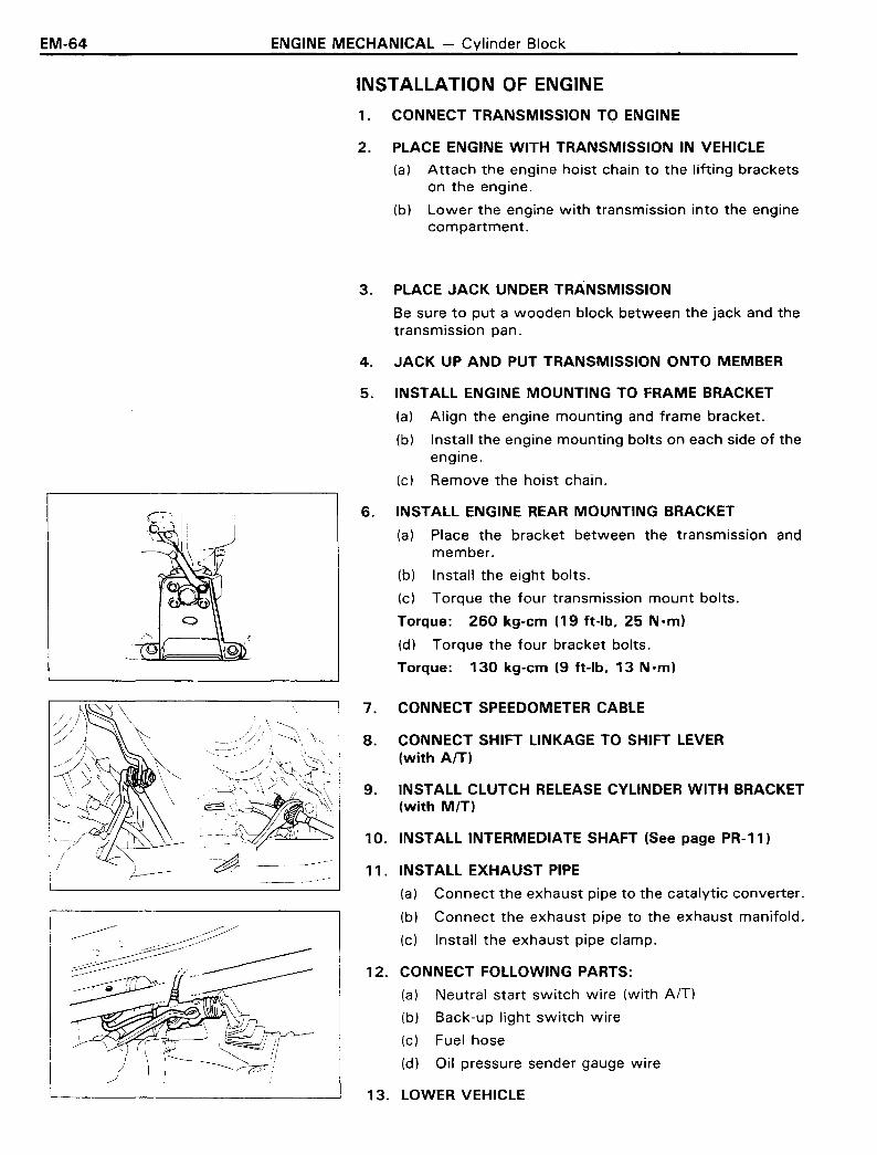
6. INSTALL ENGINE REAR MOUNTING BRACKET
(a) Place the bracket between the transmission andmember.
(b) Install the eight bolts.
(c) Torque the four transmission mount bolts.
Torque: 260 kg-em (19 ft-Ib, 25 N·m)
(d) Torque the four bracket bolts.
Torque: 130 kg-em (9 ft-Ib, 13 Nom)
10. INSTALL INTERMEDIATE SHAFT (See page PR-11)
11. INSTALL EXHAUST PIPE
(a) Connect the exhaust pipe to the catalytic converter.
(b) Connect the exhaust pipe to the exhaust manifold.
(c) Install the exhaust pipe clamp.
8. CONNECT SHIFT LINKAGE TO SHIFT LEVER(with AfT)
9. INSTALL CLUTCH RELEASE CYLINDER WITH BRACKET(with MIT)
7. CONNECT SPEEDOMETER CABLE
~\\"
~"~'
.~'~~.',' O/~,. / \
~_~~_ - I
-~' --
12. CONNECT FOLLOWING PARTS:
(a) Neutral start switch wire (with AfT)
(b) Back-up light switch wire
(c) Fuel hose
(d) Oil pressure sender gauge wire~
13. LOWER VEHICLE
ENGINE MECHANICAL - Cylinder Block EM-65
14. INSTALL SHIFT LEVER FOR INSIDE OF VEHICLE (with MIT)
15. CONNECT BOND CABLES TO ENGINE REAR SIDE AND RHSIDE
16. INSTALL COMPRESSOR TO BRACKET (with A/C)
(a) Install the compressor with four bolts.
(b) Install the drive belt and adjust the belt tension.
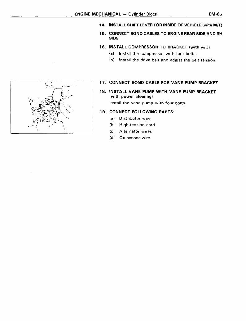
17. CONNECT BOND CABLE FOR VANE PUMP BRACKET
18. INSTALL VANE PUMP WITH VANE PUMP BRACKET(with power steering)
Install the vane pump with four bolts.
19. CONNECT FOLLOWING PARTS:
(a) Distributor wire
(b) High-tension cord
(c) Alternator wires
(d) Ox sensor wire
EM-66 ENGINE MECHANICAL - Cylinder Block
POST INSTAllATION
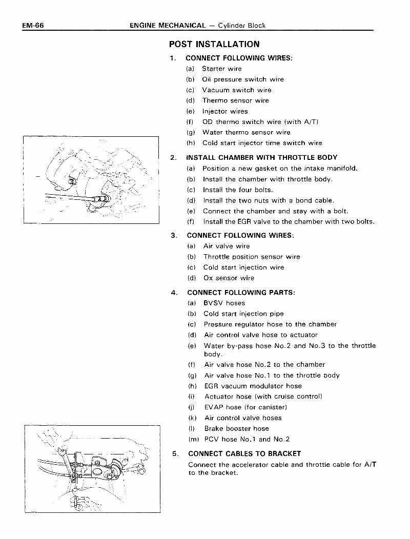
1. CONNECT FOLLOWING WIRES:
(a) Starter wire
(b) Oil pressure switch wire
(c) Vacuum switch wire
(d) Thermo sensor wire
(e) Injector wires
(f) 00 thermo switch wire (with AfT)
(g) Water thermo sensor wire
(h) Cold start injector time switch wire
2. INSTALL CHAMBER WITH THROTTLE BODY
(a) Position a new gasket on the intake manifold.
(b) Install the chamber with throttle body.
(c) Install the four bolts.
(d) Install the two nuts with a bond cable.
(e) Connect the chamber and stay with a bolt.
(f) Install the EGR valve to the chamber with two bolts.
3. CONNECT FOLLOWING WIRES:
(a) Air valve wire
(b) Throttle position sensor wire
(c) Cold start injection wire
(d) Ox sensor wire
4. CONNECT FOLLOWING PARTS:
(a) BVSV hoses
(b) Cold start injection pipe
(c) Pressure regulator hose to the chamber
(d) Air control valve hose to actuator
(e) Water by-pass hose No.2 and No.3 to the throttlebody.
(f) Air valve hose No.2 to the chamber
(g) Air valve hose No.1 to the throttle body
(h) EGR vacuum modulator hose
(i) Actuator hose (with cruise control)
(j) EVAP hose (for canister)
(k) Air control valve hoses
(I) Brake booster hose
(m) PCV hose No.1 and No.2
5. CONNECT CABLES TO BRACKET
Connect the accelerator cable and throttle cable for AfTto the bracket.
ENGINE MECHANICAL - Cylinder Block EM-67
6. INSTALL RADIATOR WITH SHROUD
(a) Install the radiator with the shroud.
(b) Connect the reservoir hose.
(c) Connect the radiator upper and lower hoses to theengine.
(d) Connect the two cooler hoses (with A/T)
7. INSTALL COUPLING FAN WITH FAN
8. INSTALL AIR CLEANER HOSE AND AIR CLEANER
9. FILL WITH ENGINE OIL
Fill the engine with new oil, API grade SF or SF/CC multigrade, fuel efficient and recommended viscosity oil.
Capacity:Dry fill 4.8 liters (5.1 US qts. 4.2 Imp. qts)Drain and refill
w 10 Oil filter change4.0 liters (4.2 US qts, 3.5 Imp. qts)
w I Oil filter change4.6 liters (4.9 US qts, 4.0 Imp. qts)
10. FILL WITH COOLANT
Close the radiator and engine drain cocks and fill withcoolant.
Total capacity: w/Heater 8.4 liters(8.9 US qts, 7.4 Imp. qts)
11. INSTALL ENGINE UNDER COVER
12. INSTALL AND ADJUST HOOD (See page BO-2)
13. CONNECT CABLE TO NEGATIVE TERMINAL OF BATTERY
14. START ENGINE
Warm up the engine and inspect for leaks.
15. PERFORM ENGINE ADJUSTMENT
16. ROAD TEST
Perform a road test
17. RECHECK COOLANT AND ENGINE OIL LEVEL

EM-68 ENGINE MECHANICAL - Cylinder Block
22RCYLINDER BLOCKPREPARATION OF REMOVAL
1. DISCONNECT CABLE FROM NEGATIVE TERMINAL OFBATTERY
2. REMOVE ENGINE UNDER COVER
3. REMOVE ENGINE HOOD
Disconnect the washer hose from the hood.
4. DRAIN COOLANT FROM RADIATOR AND CYLINDERBLOCK
5. DRAIN AUTOMATIC TRANSMISSION FLUID(with AfT)
6. REMOVE AIR CLEANER
(a) Disconnect air hoses No.1 and No.4 from the aircleaner.
(b) Remove the air cleaner.
7. REMOVE COUPLING FAN WITH FAN
8. DISCONNECT TWO HEATER HOSES
9. REMOVE RADIATOR WITH SHROUD
(a) Disconnect the two cooler hoses. (with AfT)
(b) Disconnect the radiator upper and lower hoses fromthe engine.
(c) Disconnect the reservoir hose.
(d) Remove the radiator with the shroud.
10. DISCONNECT ACCELERATOR CABLE FROMCARBURETOR
Disconnect the cable from carburetor and bracket.
11. DISCONNECT FOLLOWING WIRES:
(a) VSV wire for EVAP
(b) VSV wire for AIC
(c) Vacuum switch wire
(d) HAC wire (Ex. Calif.)
(e) Cold mixture heater wire
(f) OD thermo switch wire (for A/T)
(g) Fuel cut solenoid wire
(h) Water temperature sender gauge wire
(i) EACV wire (for Calif.)
(j) Starter wire
(k) Oil pressure switch wire
ENGINE MECHANICAL - Cylinder Block
12. DISCONNECT FOLLOWING PARTS:
(a) Brake booster hose
(b) Fuel main hose from fuel inlet pipe
(c) Fuel return hose from fuel return pipe
(d) Charcoal canister hose
13. REMOVE DRIVE BELT
REMOVAL OF CYLINDER BLOCK(See page EM-49)
PREPARATION FOR DISASSEMBLY(See page EM-51)
DISASSEMBLY OF CYLINDER BLOCK(See page EM-52)
INSPECTION OF CYLINDER BLOCK(See page EM-55)
EM-69
DISASSEMBLY OF PISTON AND CONNECTINGROD ASSEMBLY(See page EM-56)
INSPECTION OF PISTON AND CONNECTING RODASSEMBLY(See page EM-57)
REPLACEMENT OF ROD BUSHING(See page EM-58)
INSPECTION AND REPAIR OF CRANKSHAFT(See page EM-59)
REPLACEMENT OF REAR OIL SEAL(See page EM-50)

EM-70 ENGINE MECHANICAL - Cylinder Block
BORING OF CYLINDERS(See page EM-60)
ASSEMBLY OF PISTON AND CONNECTINGROD ASSEMBLY(See page EM-61)
INSTALLATION OF CRANKSHAFT, PISTONAND CONNECTING ROD ASSEMBLY(See page EM-62)
INSTALLATION OF ENGINE(See page EM-64)
POSTINSTALLATION OF CYLINDER BLOCK
1. CONNECT FOLLOWING WIRES:
(a) Starter wire
(b) Oil pressure switch wire
(c) VCS wire (Ex. Calif.)
(d) EACV wire (for Calif.)
(e) Water temperature sender gauge wire
(f) Fuel cut solenoid wire
(g) 00 thermo switch wire (for AfT)
(h) Cold mixture heater wire
(i) HAC wire (Ex. Calif.)
(j) Vacuum switch wire
(k) VSV wire for AIC
(I) VSV wire for EVAP
2. CONNECT FOLLOWING PARTS:
(a) Charcoal canister hose from the VSV
(b) Fuel return hose from the fuel return pipe
(c) Fuel main hose from the fuel inlet pipe
(d) Brake booster hose
3. CONNECT ACCELERATOR CABLE TO CARBURETOR
(a) Connect the cable to the carburetor and bracket.
(b) Install the tension spring.
4. INSTALL RADIATOR WITH SHROUD
(a) Install the radiator with the shroud.
(b) Connect the reservoir hose.
(c) Connect the radiator upper and lower hoses to theengine.
(d) Connect the two cooler hoses (with A/T)
ENGINE MECHANICAL - Cylinder Block EM-71
5. INSTALL COUPLING FAN WITH FAN
6. CONNECT TWO HEATER HOSES
7. INSTALL AIR CLEANER
(a) Connect air hoses No.1 and No.4 to the cleaner.
(b) Install the air cleaner.
8. FILL WITH ENGINE OIL
Fill the engine with new oil, API grade SF or SF/CC multigrade, fuel efficient and recommended viscosity oil.
Capacity:Dry fill 4.8 liters
(5.1 US qts, 4.2 Imp. qts)Drain and refill
w/o Oil filter change 4.0 liters(4.2 US qts, 3.5Imp. qts)
w / Oil filter change 4.6 liters(4.9 US qts, 4.0 Imp. qts)
9. FILL WITH COOLANT
Close the radiator and engine drain cocks and fill withcoolant.
Total capacity: w/Heater 8.4 liters(8.9 US qts, 7.4 Imp. qts)
10. INSTALL ENGINE UNDER COVER
11. INSTALL AND ADJUST HOOD (See page BO-2)
12. CONNECT CABLE TO NEGATIVE TERMINAL OF BATTERY
13. START ENGINE
Warm up the engine and inspect for leaks.
14. PERFORM ENGINE ADJUSTMENT
15. ROAD TEST
Perform a road test.
16. RECHECK COOLANT AND ENGINE OIL LEVEL