engineering design and construction phase iv - …mend-nedem.org/wp-content/uploads/2311b.pdf ·...
TRANSCRIPT

ENGINEERING DESIGN ANDCONSTRUCTION REPORT
PHASE IV - COMPOSITE SOIL COYERACID WASTE ROCK STUDY
HEATH STEELE MINES
MEND Report 2.3l.lb
This work was done on behalf of MEND and sponsored byNoranda-Brunswick Mining and Smelting (Heath Steele) as well as
the Province of New Brunswick, andthe Canada Centre for Mineral and Energy Technology (CANMET)
through the CANADA/New Brunswick Mineral Development Agreement (MDA)
November 1994
. --.-..-_

R E P O R T F O R
ENGINEERING DESIGN ANDCONSTRUCTION
PHASE IV - COMPOSITE SOIL COVERACID WASTE ROCK STUDY
HEATH STEELE MINES
SSC File No: 14SQ.23440-l-9060Contract File No: 23440-l-9060/01 -SQ
Our File No. 28-3562-001.1
Submitted to:
Heath Steele MinesP.O. Box 400
Newcastle, N.B.ElV 3M5
by:
AD1 Nolan Davis1133 Regent Street, Suite 407
P.O. Box 44, Station “A”Fredericton, N.B.
E3B 4Y2
Project Manager: Michael D. RileyReviewed By: Alan BellDate: November 15.1994
Table of Contents
1.0
2.0
3.0
4.0
Page
.
Table of contents........: . . . . . . . . . . . . . . . . . . . . . . . . . . . . . . . . . . . . . . . . . . . . . . i iList of Figures ......................................................... iv
ListofTables .......................................................... iv
ExecutiveSummary . . . . . . . . . . . . . . . . . . . . . . . . . . . . . . . . . . . . . . . . . . . . . . . . . . . . . . .Sommaire . . . . . . . . . . . . . . . . . . . . . . . . . . . . . . . . . . . . . . . . . . . . . . . . . . . . . . . . . . . . . vi
INTRODUCTION . . . . . . . . . . . . . . . . . . . . . . . . . . . . . . . . . . . . . . . . . . . . . . . . . . . . . . . .
BACKGROUND . . . . . . . . . . . . . . . . . . . . . . . . . . . . . . . . . . . . . . . . . . . . . . . . . . . . . . . . .2.1 General.. . . . . . . . . . . . . . . . . . . . . . . . . . . . . . . . . . . . . . . . . . . . . . . . . . . . . . . . . .2.2 Waste Rock, Pile 7/12 . . . . . . . . . . . . . . . . . . . . . . . . . . . . . . . . . . . . . . . . . . . . . .3
COVERDESIGN . . . . . . . . . . . . . . . . . . . . . . . . . . . . . . . . . . . . . . . . . . . . . . . . . . . . . . . .3.1 Design Rationale . . . . . . . . . . . . . . . . . . . . . . . . . . . . . . . . . . . . . . . . . . . . . . . . . .53.2 Engineering Design . . . . . . . . . . . . . . . . . . . . . . . . . . . . . . . . . . . . . . . . . . . . . . . .6
3.2.1 Engineering Drawings . . . . . . . . . . . . . . . . . . . . . . . . . . . . . . . . . . . . . . . .63.2.2 Project Specifications . . . . . . . . . . . . . . . . . . . . . . . . . . . . . . . . . . . . . . . . .6
3.3 Construction Materials . . . . . . . . . . . . . . . . . . . . . . . . . . . . . . . . . . . . . . . . . . . . . .93.3.1 Granular Soils . . . . . . . . . . . . . . . . . . . . . . . . . . . . . . . . . . . . . . . . . . . . . .93.3.2 GlacialTill . . . . . . . . . . . . . . . . . . . . . . . . . . . . . . . . . . . . . . . . . . . . . . . . .9
COVERCONSTRUCTION . . . . . . . . . . . . . . . . . . . . . . . . . . . . . . . . . . . . . . . . . . . . ..104.1 Contractor Selection . . . . . . . . . . . . . . . . . . . . . . . . . . . . . . . . . . . . . . . . . . . . . . . 104.2 Construction Quality Control . . . . . . . . . . . . . . . . . . . . . . . . . . . . . . . . . . . . . . . . 1 04.3 Construction Activities ............................................ 11
4.3.1 Surface Preparation . . . . . . . . . . . . . . . . . . . . . . . . . . . . . . . . . . . . . . . . . 1 14.3.2 SandBase. . . . . . . . . . . . . . . . . . . . . . . . . . . . . . . . . . . . . . . . . . . . . . . . . 134.3.3 Composite Cover . . . . . . . . . . . . . . . . . . . . . . . . . . . . . . . . . . . . . . . . . . . 13
4.3.3.1 Borrow Source . . . . . . . . . . . . . . . . . . . . . . . . . . . . . . . . . . . . . . . 134.3.3.2 Placement . . . . . . . . . . . . . . . . . . . . . . . . . . . . . . . . . . . . . . . . . . . 1 4
4.3.4 Granular Cover and Erosion Protection . . . . . . . . . . . . . . . . . . . . . . . . . . 154.4 Lysimeter Installation . . . . . . . . . . . . . . . . . . . . . . . . . . . . . . . . . . . . . . . . . . . . . 1 64.5 Outfall Structure . . . . . . . . . . . . . . . . . . . . . . . . . . . . . . . . . . . . . . . . . . . . . . . . . . 164.6 In Situ Permeability Testing . . . . . . . . . . . . . . . . . . . . . . . . . . . . . . . . . . . . . . . . 174.7 Summary of Cover Construction . . . . . . . . . . . . . . . . . . . . . . . . . . . . . . . . . . . . 19
i i
5.0
6.0
7.0
8.0
MONITORING INSTRUMENTATION . . . . . . . . . . . . . . . . . . . . . . . . . . . . . . . . . . . . .205.1 Project Requirements . . . . . . . . . . . . . . . . . . . . . . . . . . . . . . . . . . . . . . . . . . . . . .205.2 WasteRockPile..................................................2 0
5.2.1 Instrumentation Clusters . . . . . . . . . . . . . . . . . . . . . . . . . . . . . . . . . . . . .205.2.2 Pore Gas Measurements . . . . . . . . . . . . . . . . . . . . . . . . . . . . . . . . . . . . . .225.2.3 Temperature Measurement . . . . . . . . . . . . . . . . . . . . . . . . . . . . . . . . . . .22
5.3 Composite Soil Cover . . . . . . . . . . . . . . . . . . . . . . . . . . . . . . . . . . . . . . . . . . . . .225.3.1 Soil Moisture Content . . . . . . . . . . . . . . . . . . . . . . . . . . . . . . . . . . . . . . .245.3.2 Temperature . . . . . . . . . . . . . . . . . . . . . . . . . . . . . . . . . . . . . . . . . . . . . . .245.3.3 Soil Suction . . . . . . . . . . . . . . . . . . . . . . . . . . . . . . . . . . . . . . . . . . . . . . .24
5.4 Meteorological Data . . . . . . . . . . . . . . . . . . . . . . . . . . . . . . . . . . . . . . . . . . . . . . .255.5 Automated Monitoring System . . . . . . . . . . . . . . . . . . . . . . . . . . . . . . . . . . . . . .255.6 Collection System - Seepage Through Cover . . . . . . . . . . . . . . . . . . . . . . . . . . .255.7 Instrumentation Monitoring Equipment Summary . . . . . . . . . . . . . . . . . . . . . . .26
MONITORINGRESULTS . . . . . . . . . . . . . . . . . . . . . . . . . . . . . . . . . . . . . . . . . . . . . ..2 86.1 GaseousOxygen . . . . . . . . . . . . . . . . . . . . . . . . . . . . . . . . . . . . . . . . . . . . . . . ..2 86.2 Temperature.....................................................3 16.3 GaseousCO, . . . . . . . . . . . . . . . . . . . . . . . . . . . . . . . . . . . . . . . . . . . . . . . . . . ..3 16.4 SeepageThroughCover............................................3 16.5 LeachateQuality . . . . . . . . . . . . . . . . . . . . . . . . . . . . . . . . . . . . . . . . . . . . . . . ..3 5
6.5.1 Soil Suction . . . . . . . . . . . . . . . . . . . . . . . . . . . . . . . . . . . . . . . . . . . . . . .366.5.2 Moisture Content . . . . . . . . . . . . . . . . . . . . . . . . . . . . . . . . . . . . . . . . . . .37
CONCLUSIONS . . . . . . . . . . . . . . . . . . . . . . . . . . . . . . . . . . . . . . . . . . . . . . . . . . . . . ..3 8
REFERENCES . . . . . . . . . . . . . . . . . . . . . . . . . . . . . . . . . . . . . . . . . . . . . . . . . . . . . . ..3 9
Appendix I - Project SpecificationsAppendix II - Laboratory Test ResultsAppendix III - In Situ Density Test ResultsAppendix IV - Monitoring Data
Drawings No F9 l-057- 1 Site Plan, Composite Soil Cover, Waste Rock Pile 7112F9 l-057-2 Construction Details, Composite Soil Cover, Waste Rock Pile 7112F91-057-3 Construction Details, Composite Soil Cover, Waste Rock Pile 7112
. . .1 1 1
List of Figures
Figure 2-lFigure 4- 1Figure 4-2Figure 5-lFigure 6- 1Figure 6-2Figure 6-3Figure 6-4
SitePlan . . . . . . . . . . . . . . . . . . . . . . . . . . . . . . . . . . . . . . . . . . . . . . . . . . . . . . . . . 4Cover Construction Detail . . . . . . . . . . . . . . . . . . . . . . . . . . . . . . . . . . . . . . . . . . 12Outfall Structure . . . . . . . . . . . . . . . . . . . . . . . . . . . . . . . . . . . . . . . . . . . . . . . . . . 18Instrumentation Cluster . . . . . . . . . . . . . . . . . . . . . . . . . . . . . . . . . . . . . . . . . . . .2 1Gaseous Oxygen vs. Time, Pile 7/12 . . . . . . . . . . . . . . . . . . . . . . . . . . . . . . . . . .29Gaseous Oxygen Profile, Pile 7/12 . . . . . . . . . . . . . . . . . . . . . . . . . . . . . . . . . . .30Temperature vs. Time, Pile 7/12 . . . . . . . . . . . . . . . . . . . . . . . . . . . . . . . . . . . . .32Temperature Profile, Pile 7/12 . . . . . . . . . . . . . . . . . . . . . . . . . . . . . . . . . . . . . . .33
List of Tables
Table 5-l Monitoring Sensors, Pile 7/12 . . . . . . . . . . . . . . . . . . . . . . . . . . . . . . . . . . . . . . .23Table 5-2 Instrumentation, Pile 7/12 . . . . . . . . . . . . . . . . . . . . . . . . . . . . . . . . . . . . . . . . . .27Table 6-l Discharged Quantities, Outfall Structure . . . . . . . . . . . . . . . . . . . . . . . . . . . . . . .34Table 6-2 Rainfall Lysimeter Measurements, Pile 7/12 . . . . . . . . . . . . . . . . . . . . . . . . . . . .34Table 6-3 Leachate Water Quality, Pile 7112 . . . . . . . . . . . . . . . . . . . . . . . . . . . . . . . . . . . .35Table 6-4 Soil Suction, Gypsum Block Method, Pile 7/12 . . . . . . . . . . . . . . . . . . . . . . . . .36Table 6-5 Volumetric Moisture Content, TDR Method, Pile 7/12 . . . . . . . . . . . . . . . . . . . 3 7
iv

Executive Summary
A 130 cm thick composite soil cover was constructed on an experimental waste-rock pile at theHeath Steele Mines site near Newcastle, New Brunswick. The cover consists of a 30 cm thick sandbase, a 60 cm thick compacted glacial till, a 30 cm thick granular layer, and a final 10 cm thick gravellayer for erosion protection. The till was compacted on the sand base in three finished lifts each of20 cm thickness. Results of a preconstructed pad test indicated six passes of a 5 tonne vibratorycompactor were required to attain the design specifications of 95 percent of the Modified Proctormaximum dry density at a moulding water content of 2-3 percent wet of the optimum. Thesecompaction specifications also ensure that the till has a degree of water saturation of at least 95percent, which is required to reduce oxygen and acid fluxes in the underlying pile. Quality controlmeasures were taken during the construction to ensure the specifications were followed. Monitoringinstrumentation was installed during the construction of the cover.
Results indicate a reduction in gaseous oxygen concentrations in the pile from 20 percent beforecover to about 1 percent after cover placement. The decreased oxygen penetration implies reducedoxygen flux and acid production. Volumetric water-contents averaged about 32 percent in the tillimmediately following cover installation and 7 months later. The water-content data are corroboratedby soil suction measurements. Temperatures in the pile have decreased following cover installationbut appear to be more influenced by climatic variability than by a decrease in heat production andhence sulphide mineral oxidation. Observed discharge from two lysimeters, installed below the coverindicate infiltration of 2 percent of precipitation during a 55-day period when rainfall was heavy. Thevolume of the seepage has been reduced but the quality from the pile has not changed since coverinstallation. Further monitoring will be required to confirm the reduction in acid production.
V

Sommaire
Une couverture de sol composite de 130 cm d’epaisseur a été construit sur une pile expérimentale destériles sur le site de la mine Heath Steele près de Newcastle au Nouveau-Brunswick. La couvertureconsiste d’une couche de fondation de sable de 30 cm d’epaisseur, un till glaciaire compacté de 60 cm,un sol granulaire de 30 cm, et finalement une couche de gravier de 10 cm d’epaisseur commeprotection contre l'érosion. Le till a éte mis en place sur la fondation de sable en trois couchescompactées de 20 cm d’epaisseur. Les résultats d’une surface d’essai avant la construction ont indiqueque six passes au compacteur vibrateur de 5 tonnes étaient nécessaires pour atteindre les devis decompactage, ce qui correspond à 95 pourcent de la densité sèche maximale du Proctor modifié et àune teneur en eau de mise en place de 2-3 pourcent du côté humide de l’optimum. Ces critèresassurent également que le till ait un degré de saturation en eau d’au moins 95 pourcent, requis pourréduire les flux d’oxygene et d’acide dans la pile sous-jacente. Des mesures de contrôle de qualite onté t é prises au cours de la construction afin d’assurer le respect des plans et devis. Des instruments demesures ont aussi été installés durant la construction de la couverture.
Les résultats indiquent une reduction des concentrations d’oxygene gazeux dans les stériles, passantde 20 pourcent avant la mise en place de la couverture à 1 pourcent après la mise en place de lacouverture. La diminution de la penetration d’oxygene indique implicitement une reduction du fluxd’oxygène et de la production d’acide. Les teneurs en eau volumétriques étaient en moyenne de 32pourcent dans le till, immédiatement après la mise en place de la couverture ainsi que 7 mois plustard. Les données de teneur en eau concordent avec les mesures de succion dans le sol. Lestemperatures dans l’halde ont diminué suite à l’installation de la couverture, mais semblent être plusintluencées par les variations climatiques que par la diminution de la production de chaleur pouvantprovenir de l’oxydation du soufre present dans les stériles miniers. Les debits observes dans deuxlysimbtres installés sous la couverture indiquent un taux d’infiltration d’environ 2 pourcent de laprecipitation au cours d’une période de 55 jours durant laquelle la pluie a été abondante. Le volumed’infiltration a é t é réduit et la qualité du lixiviat après l’installation de la couverture n’a pas change.11 est necessaires que le suivi de la couverture soit prolongé afin de confirmer la reduction d’acide.
vi

phase IV- Composite Soil Cover 1Acid Waste Rock Study - Health Steele Mimes
1.0 INTRODUCTION
Sulphide ore mining in Northeast New Brunswick has produced waste rock piles containing acidgenerating pyritic rock. The Heath Steele Mines (HSM) property located in this region wasdeveloped in the late 1950’s before the implications of acid mine drainage (AMD) were fullyappreciated. The property presently contains in excess of 20 acid generating waste rock piles. Sincethis region of New Brunswick is famous for salmon runs and sports fishing, the presence of acidgenerating waste rock within the watersheds is a major concern. Under the Clean Environment Act.,(NB Regulation 87-83) regulatory agencies and mine operators require a practical, economicalsolution to the waste rock problem.
The “Heath Steele Waste Rock Study,” which is registered within the national MEND Program, hasbeen in progress since 1988. The objectives of the project, which is currently funded by BrunswickMining and Smelting Corporation (BMS) and both the governments of New Brunswick and Canada,are to evaluate the performance of a soil cover placed over an existing acid waste rock pile at HSM,and to assess the cover’s effectiveness as a method for long term management of acid generatingwaste rock. The study was developed in four phases with funding for the first three phases approvedon December 16, 1988. The four phases of the overall project are as follows:
Phase I -
Phase II -
Phase III -
Phase IV -
Selection of four waste rock piles for monitoring andevaluationInstallation of monitoring equipment in the four piles identifiedin Phase I to define waste rock characteristics and backgrounddataGeotechnical and column testing to evaluate the performancecharacteristics of potential coversPlacement of soil cover and performance monitoring
Phase I was completed in the summer of 1988 with Phases II and III completed at the end of 1990.The final report (MEND Project 2.3 1. la) containing Phases I to III is available from MEND.
On February 28, 1991, a proposal was submitted by HSM for Phase IV of the study for whichfunding was approved on July 4, 1991. The following report, which documents the results of theproject to the end of October, 1993, specifically addresses the engineering design and constructionof the composite soil cover placed on waste rock Pile 7/12 in August and September 1991. It alsopresents the subsequent two years of performance monitoring data, including reference Pile 18.
ADI Nolan Davis Inc. 28-3562-001-l

Pkose IV- Composite Soil Co&rAcid Waste Rock Sthi’y - Heads Steele Mimes
2
2 . 0 BACKGROUND
2.1 General
In Phases I and II of the “Heath Steele Waste Rock Study”, four selected waste rock piles, identifiedas Pile 1 SA, 18B, 17 and 7/1.2, were instrumented and monitored to define the background conditionsrelated to the acid generation process. The instrument clusters to measure both temperature andoxygen concentrations in each of the four selected waste rock piles were installed at nominal l-2metre depth intervals, The temperature and oxygen concentrations were measured in waste rock Piles1 SA, 18B and 17 from November 1988 and Pile 7112 from June 1989 on a monthly basis toSeptember 199 1.
It is recognized that oxygen transport is the dominant rate-controlling mechanism in most acidgenerating waste rock piles and that the major oxygen transport mechanism is gas transfer throughthe pore spaces of the pile. Gas transfer is by a combination of diffusion, convection and advection,with the inter-relationships between these mechanisms dependent on factors such as pile geometry,pile composition, pile placement technique and pile history. A key finding of Phase II of the studywas that the depth profiles of oxygen and temperature for each of the four piles monitored differedsignificantly from pile to pile yet were reasonably consistent within a given pile. It is apparent thatthe manner in which gas transfer occurs within each of the HSM waste rock piles is different despitemany similar characteristics and geographic proximity.
The waste rock piles at the HSM site have already oxidized and presumably contain large volumesof stored acidity. Furthermore, a substantial amount of unoxidized sulphide minerals is present withinthe HSM waste rock piles, as shown in the mineralogical data (Nolan Davis, 1990). This unoxidizedmaterial will oxidize upon contact with oxygen and water. Therefore, a management system for theacid generating waste rock at HSM must not only contain the stored acidity but also inhibit theoxidation process and thus reduce the volume of generated mine AMD. An effective cover systemwill control both the water and the rate of oxygen infiltration into the waste rock pile.
The design of a saturated soil cover required the development of methodologies for predicting itslong term hydraulic and diffusive behaviour. Phase III of the “Heath Steele Waste Rock Study”,carried out by Noranda Technology Centre (NTC), involved the development of an appropriate soilcover design based on the performance characteristics of natural soils in the vicinity of HSM. TheNTC studies indicated that a three layer composite soil cover, consisting of a fine grained saturatedglacial till sandwiched between two coarse-grained granular layers would be an effective managementapproach. Glacial till, when compacted at a water content slightly more wet than the optimum, hasa low hydraulic conductivity and will also provide an effective oxygen barrier. The coarse-grainedgranular layers above and below the glacial till will help prevent it from drying out.
ADI Nolan Davis Im 2&3562-001-l
Phase IV- Composite Soil Co&rAcid Waste Rock Study -.Heath Steet% Mimes
3
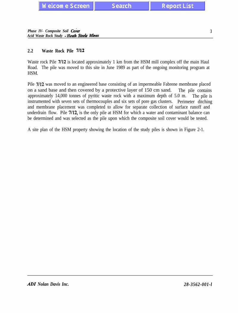
2.2 Waste Rock Pile 7/12
Waste rock Pile 7/12 is located approximately 1 km from the HSM mill complex off the main HaulRoad. The pile was moved to this site in June 1989 as part of the ongoing monitoring program atHSM.
Pile 7/12 was moved to an engineered base consisting of an impermeable Fabrene membrane placedon a sand base and then covered by a protective layer of 150 cm sand. The pile containsapproximately 14,000 tonnes of pyritic waste rock with a maximum depth of 5.0 m. The pile isinstrumented with seven sets of thermocouples and six sets of pore gas clusters. Perimeter ditchingand membrane placement was completed to allow for separate collection of surface runoff andunderdrain flow. Pile 7/12, is the only pile at HSM for which a water and contaminant balance canbe determined and was selected as the pile upon which the composite soil cover would be tested.
A site plan of the HSM property showing the location of the study piles is shown in Figure 2-1.
ADI Nolan Davis Inc. 28-3562-001-l

SITE LOCATION
WHJRSTY
ADI NOLAN DAVIS
.
KlLOMElRES
F I G U R E 2 - 1
SITE PLAN - HEATH STEELE MINES
28-3562-l JUNE 1994

Phase IV - Composite Soil CobAcid Waste Rock Study - Heath St&e& Mimes
5
3 . 0 COVER DESIGN
3.1 Design Rationale
NTC evaluated a number of soil cover designs for placement over Pile 7/12. Studies indicated thatan initially saturated single soil layer placed on a waste rock pile will ultimately desaturate by drainageand moisture losses due to evaporation. The diffusion coefficient of oxygen for such a system,although initially low, will increase with time, resulting in increased oxygen diffision into the pile.Furthermore, a cover with only one soil layer could potentially dry out and crack over time, especiallyif the soil has a high clay content.
For Pile 7/12, NTC proposed a composite soil cover consisting of a fine grained saturated glacial tillsandwiched between two coarse grained granular layers as an effective oxygen barrier based on thefollowing rationale:
0 The base granular material will drain to residual saturation before the till. Atresidual saturation, the granular layer is unsaturated, thus minimizing thehydraulic conductivity and maintaining saturation of the till during dryperiods.
ii) The fine grained glacial till compacted at a moisture content slightly wet ofoptimum can be expected to have a low hydraulic conductivity while actingas an effective moisture and oxygen barrier.
iii) The overlying coarse grained granular layer is required to prevent the till layerfrom d,ying out at the surface as well as acting as a recharge layer to theunderlying till.
A surfrcial coarse-grained granular layer for erosion protection was also included in the design.
The NTC designed composite soil cover adopted for the Phase IV Study requires a 30 cm basegranular layer, a 60 cm saturated glacial till, a 30 cm overlying coarse-grained granular layer and a10 cm thick erosion protection layer. The thickness of the different layers are designed to maintainthe glacial till saturated for a minimum of 50 days without precipitation.
2 8 - 3 5 6 2 - 0 0 1 - l

Phase IV - Composite Soil CoierAcid Waste Rock Study - Heath Steele Mimes
6
3.2 Engineering Design
3.2.1 Engineering Drawings
The engineering design involved the preparation of engineering drawings and project specificationsrequired for the actual construction of the cover based on the design criteria provided by NTC.During the summer of 1991, a total of three engineering drawings plus project specifications werecompleted by AD1 Nolan Davis Inc., formerly Nolan Davis and Associates (NB) Ltd.
The AD1 Nolan Davis’ Drawing Nos F91-057-1, F91-057-2, and F91-057-3 were produced as partof the engineering design. The first drawing, F91-057-1, presents the results of the site surveyscarried out on July 12, 1991. AD1 Nolan Davis’ Drawings Nos F91-057-2 and F91-057-3, showconstruction and instrumentation details respectively. The final slope of the completed pile cover is3: 1 (Horizontal: Vertical) with the layer thickness as previously noted. Special attention was alsogiven to sealing the glacial till to the existing Fabrene membrane. The three drawings were includedas part of the tender package provided to local contractors during tendering and these were used asengineering construction drawings during the subsequent cover placement. Reduced scalereproductions of the drawings are appended at the end of this report.
3.2.2 Project Specifications
The project specifications prepared by AD1 Nolan Davis defined the specific requirements for eachof the following identified work items:
Borrow Source;Surface Preparation;Sand Base;Impermeable Cover;Granular Cover;Erosion Protection; andLeachate Collection.
A copy of the project specifications is provided in Appendix I.
The following sections provide additional details on the specific project requirements for the workitems noted above.
ADI Nolan Davis Inc. 28-3562-001-l

Phase IV- Composite Soil CoverAcid Waste Rtwk S&iy -Heath Steele Mines
7
Borrow Source
The construction of the cover required that a source of glacial till be found for the impermeablecover. The selected borrow source was identified by HSM.
Surface Preparation
The initial task in the placement of the composite soil cover was the surface preparation of waste rockPile 7/12. This included filling all depressions and large voids on the side slopes and top of the pilewhile removing any high points by grading. Depressions and large voids were infilled with crushedrock or waste rock from other areas of the pile. The crushed rock for infilling was specified ascrushed rock meeting New Brunswick Department of Transportation specifications for minus 37.5mm crushed rock for both gradation and quality.
Sand Base
The sand base was specified to have a minimum thickness of 30 cm over the entire waste rock pilemeeting the following gradation requirements:
60% ranging between 0.5 and 4.0 mm diameterD,, ranging between 0.35 and 0.40 mm diameter
Specifications required that the sand base be placed and compacted to 92 percent Modified Proctordensity (ASTM D 1557) with the final finished surEace to be flat with surface irregularities within *25mm average grade.
Impermeable Cover
The impermeable cover was specified as a local glacial till soil meeting the following specifications:
0 Grain Size (ASTM D 422)Maximum particle size of 30 mm
, Minimum percent finer than 0.075 mm particle size of 40% by dry weightMinimum percent finer than 0.002 mm particle size of 10% by dry weight
D,, ranging between 0.001 and 0.003 mm particle size
0 Moisture Content (ASTM D 2216)-2 to +4% of optimum moisture content
ADI Nolan Davis Inc. 28-3562-001-l

Phase IV - Composite Soil Co%Acid Waste Rock Study - Heaih Steele Mimes
8
0 Atterberg Limits (ASTM D 4318)Liquid Limit > 30 and Plasticity Index > 15
0 Moisture Density Relations (ASTM D 1557)Soil compacted to 95% of maximum dry Modified Proctor density at amoisture content of -2 to +4% of optimum.
0 Hydraulic Conductivity (ASTM D 2434)Coefficient of permeability (k) 1 x lo-’ cm/set or less,
Specifications required that the glacial till cover be placed in maximum 20 cm thick lifts andcompacted to 95% of its Modified Proctor density with the final compacted surface of the glacial tillto be flat with surface irregularities within f 25 mm of average grade.
A tight seal between the existing base Fabrene membrane and glacial till cover was also specified(AD1 Nolan Davis’ Drawing No. F91-057-2).
Granular Cover
The 30 cm thick granular cover was specified as a well graded pit run sand and gravel or equivalentcrushed rock meeting the following requirements:
Maximum particle size of 50 mmMaximum percent finer than 0.075 mm size of 8% by weight
Specifications required the granular cover to be placed in 15 cm thick lifts and compacted to 92percent of its Modified Proctor density (ASTM 1557).
Erosion Protection
Erosion protection to be placed over the complete soil cover was specified as a minimum 10 cm thicklayer of coarse gravel or crushed rock having a maximum particle size of 75 mm and 15 percent byweight finer than 4.75 mm.
ADI Nolan Davis Inc. 28-3562-001-l
Phase IV- Composire Soil CoiwAcid Waste Rock Study - Heath Steele Mimes
9
Leachate Collection
Final design required that the leachate collected from within the pile and cover seepage from the twoinstalled lysimeters be directed via installed piping to an outfall structure located at the base of Pile7/12 on the north face. Water samples are collected from the outfall structure which drains to CampBrook Pond via a 100 mm PVC pipe.
3.3 Construction Materials
3.3.1 Granular Soils
Contractors intending to submit a proposal for construction of the composite soil cover were requiredto submit samples of granular materials they proposed to use. The samples were forwarded to NTCfor acid generating potential testing. A total of 9 samples from various sources were tested by NTCand the test results indicated that the granular materials were not acid generating material.
The granular soils used for sand base, granular cover and erosion protection were all screenedaggregates from the Shaddick Lake deposit located 15 km from the site.
3.3.2 Glacial Till
In the summer of 1988, glacial till samples were collected from five different sites in the vicinity ofHSM by NTC and tested for use in a composite soil cover. The results of this testing and analysisare presented in MEND Project Report 2.3 1. la. Of the five samples tested, the recommended tillsource was from the Stratmat CNE Extension site. However, it was concluded that the deposit wasuneconomical because of the haul distance (20 km) and poor condition of the access road.
In late July early August 1991, HSM carried out an extensive survey of the mine property in thevicinity ofPile 7/12 for alternative source of glacial till. The field surveys, carried out using a pionjardrill, identified the Anderson Road Borrow Pit as a possible source, at a haul distance ofapproximately 3.2 km from the site (see Figure 2-l). Cost proposals from the contractors forconstruction of the composite cover on Pile 7/12 were based on using glacial till from this source.
A third source of glacial till, located 2.5 km east of Pile 7/12, was identified by HSM prior to the startof construction. Testing carried out by NTC found this source, referred to as the Shaft No. 5 BorrowSource, suitable for use in cover construction, This glacial till source was ultimately selected for use.Its location is shown on Figure 2-1.
ADI Nolan Davis Inc. 28-3562-001-l

Phase IV - Composite Soil CoiwAcid Waste Rock Study - Heatk Steele Mimes
10
4.0 COVER CONSTRUCTION
4.1 Contractor Selection
Eight contractors from the Newcastle-Bathurst area were invited to submit proposals for theconstruction of the cover. At an August 12, 1991 site meeting, the project requirements werepresented to the contractors. Four proposals were received with the proposal submitted by ATCOConstruction of Newca.stle selected on the basis of both price and experience.
4.2 Construction Quality Control
The composite soil cover was placed on Pile 7/12 during the period August 28 to September 19,1991. The work was carried out under the full time supervision of AD1 Nolan Davis personnel whomaintained daily records of site activities, inspected each of the placed soil layers and carried out insitu density testing and laboratory testing as required.
The quality control procedures implemented by AD1 Nolan Davis during construction to ensureproject specifications were achieved. This included:
0
ii)
iii)
iv)
v)
4
Laboratory testing was carried out at an on-site temporary laboratory to ensure thatthe soils provided met project requirements for gradation. The glacial till was alsotested on site for moisture content and Atterburg limits.
Moisture density relations tests were conducted prior to the placement of each of thesoils to determine the soil’s maximum dry density and optimum moisture content. Inthe case of the glacial till, a second test was carried out during construction.
On-site stockpiles of each material to be placed were visually inspected on a regularbasis for consistency of quality.
The thickness of each placed layer was regularly measured prior to placement of thenext layer using survey level equipment.
The compaction of each layer was monitored to ensure the minimum number ofpasses of the vibratory compactor were completed.
In-situ density testing utilizing a nuclear density gauge were conducted during theplacing operations to ensure that all soils were properly compacted at the specifiedmoisture contents and required density.
ADI Nolan Davis Inc. 28-3562-001-l

Phase IV - Composite Soil CocerAcid Waste Rock Study - Heath Steele Mimes
1 1
vii) The calibration of the nuclear density gauge was checked daily prior to usage.
The results of the laboratory testing are summarized in the following sections and are included inAppendix II. In situ density test results are presented in Appendix III.
4.3 Construction Activities
4.3.1 Surface Preparation
The initial task for the cover placement was the preparation of the surface of Pile 7/12. For the pileshaping, a Caterpillar 215 hydraulic excavator, working from the top of the pile was used to removethe high points on the side slopes while infilling surface voids and depressions. The top of the pilewas levelled with the hydraulic excavator and a small Caterpillar D3 tractor. Two holes, eachmeasuring about 3.5 x 2 x 1.2 m were excavated at the top of the pile for the placement of twolysiieters. The excavated material was utilized for infilling the voids around the lysimeters. About50 tonnes of crushed rock were used to fill voids and depressions in some areas of the surface.
The project specifications required that a Fabrene membrane liner be placed at the base of the pile tohave a tight seal between the Fabrene liner and the glacial till. As part of the surface preparation,sand and gravel around the perimeter of the pile was excavated manually to expose approximately0.3 m of membrane at the base of the pile. A double-layered 6 mil polyethylene was placed over theexposed Fabrene membrane and keyed into the glacial till core of the composite soil cover, asindicated on Figure 4-l. The polyethylene was put as an additional measure to improve the sealbetween the composite soil cover and the Fabrene membrane.
The final prepared surfaces of Pile 7/12 were relatively flat with all major voids infilled and highpoints removed. No new waste rock was added to the pile during surface preparation.
ADI Nolan Davis Inc. 28-3562-001-l

100 mm lHICK EROSION PROTECllON3
500 mm THICK SAND AND CRAVEL COVER
- 600 mm THICK COMPACTED GLACIAL llLL
- PREPARED BASE - SOIL BERM
F A B R E N E M E M B R A N E
4,9.t
METRES
FIGURE 4-1
COVER CONSTRUCTION DETAIL
28-3562-l JUNE 1994

Phase IV - Composite Soil CoverAcid Waste Rock Strrdy -Heath Steele Mimes
1 3
4.3.2 Sand Base
The prepared surface of Pile 7/12 was covered with a minimum 30 cm thick layer of medium tocoarse sand from the Shaddick Lake deposit. The sand was placed with a front end loader, spreadwith a small Case 3 10 tractor, and compacted with a 5 tonne vibratory compactor. A minimum offour passes was used to compact the sand base with water applied to assist in the compaction to therequired density.
The final side slope of the sand base was graded to 3H: 1V slope as required in the design. In areasnear the outer edges of the pile, a layer of greater than 30 cm thickness was provided to maintain therequired grades.
The results of one grain size analysis carried out on the sand base material, shown on Figure II-l ofAppendix II, shows that the sand is comprised of 4 percent gravel particles, 90 percent sand particles,and 6 percent silt and clay size particles.
The compacted sand base met the design criteria as specified by NTC for gradation and wascompacted to the specified in-situ density.
4.3.3 Composite Cover
4.3.3.1 Borrow Source
The borrow source for the glacial till was located approximately 2.5 km east of Pile 7/12 and to theimmediate south ofwaste rock Pile 17. Seven test pits or trenches were completed in the deposit byHSM using a track mounted hydraulic excavator to delineate the extent of the deposit. Visual andtactile inspection of the till deposit indicated that the deposit was sand and gravel within a clayey siltmatrix typical of glacial deposits in this area. Cobbles and boulders up to 1 m in diameter were notedthroughout the deposit. Representative samples of glacial till from the test pits were forwarded toNTC for analysis. The results of four grain size analyses conducted on these samples, shown inFigure II-2 of Appendix II, indicated the tii to comprise of lo-28 percent gravel, lo-29 percent sand,39-48 percent silt and 5-18 percent clay size particles. The natural moisture content of the testsamples ranged from 15.8-24.8 percent. On the basis of this testing, the soil was approved for useby NTC. Based on observations during the field investigation, the amount of the glacial till availablewas judged to be sufficient (1500 m”) for the construction of the composite soil cover.
During placement of the glacial till, representative samples were recovered daily for subsequentlaboratory analysis. The results of seven grain size analyses carried out on these samples, shown onFigures II-3 and II-4 of Appendix II, indicated that the glacial till was comprised of 13-37 percent
ADI Nolan Davis Inc. 28-3562-001-l

Phase IV- Composite Soil CobAcid Waste Rock Study - Heath Steel& Mimes
1 4
gravel, 25-35 percent sand, 25-43 percent silt and 7-14 percent clay size particles. Most cobbles andboulders found in the till were removed by the contractor prior to placement and compacting.
The results of two Moisture Density Relations (ASTM D1557) tests carried out on representativesamples of the glacial till are presented in Figure II-5 of Appendix II. The optimum moisture contentwas determined to be 13.5 percent with a maximum dry density of 1965 kg/m3.
The results of three Atterburg limit tests carried out on the glacial till samples indicate the soil to havea liquid limit of 27-28 and a plasticity index of 5-6.
The glacial till met the design criteria as specified by NTC for Atterburg limits and generally, NTCgradation requirements. Three of the samples tested had a percentage material finer than 0.002 mmparticle size (clay size) less than the specified 10 percent while exceeding the minimum 40 percentspecified minimum total tines (silt and clay size particles) content. With the high percentage of totalfines, the low percentage clay size particles it is not expected to impact on the long term coverperformance.
4.3.3.2 Placement ’
Prior to placement of glacial till on the Pile 7112, a field test strip measuring approximately 5 x 10 min plan was constructed at the southwest comer of Pile 7/12 to test the method of placement andcompaction technique. Glacial till was placed over the test strip in maximum 20 cm thick lifts andcompacted with the 5 tonne vibratory compactor with in-situ density testing carried out after eachpass of the compactor. A total of three layers of till, equalling approximately 60 cm in thickness wereplaced and compacted. The results of the in situ density tests indicated that a minimum of six passesof the 5 tonne vibratory compactor would be required to achieve the specified Modified Proctordensity.
On September 3, 1993, the contractor cleared and grubbed the borrow source area and-startedexcavating the glacial till. The material was trucked to Pile 7/12 where it was stockpiled at the baseof the pile. The moisture content of the glacial till at the source was found to be 5% or more abovethe optimum. Consequently, the glacial till was allowed to dry in the stockpile prior to placement.From the stockpile, the dried glacial till was transported to Pile 7/12 with a Hough payloader andspread with a small bulldozer. Cobbles and boulders in the glacial till were removed manually, bothfrom the stockpiled area and as the till was being placed. The glacial till was placed in maximum 20cm lifts and compacted with the 5 tonne vibratory compactor.
Approximately 1500 m3 of glacial till was placed and compacted on Pile 7/12 from September 4 toSeptember 14, 1991. The weather during the period from September 3 to 10 was generally sunny
ADI Nolan Davis Inc. 28-3562-001-l

Phase IV- Composite Soil Co&vAcid Waste Rock Study - Heath Steele Mimes
15
with moderate temperatures, allowing for placement of the glacial till on the west, south and eastslopes of the pile, and the initial top layer of the pile. However a major rainstorm on September 10,1991 resulted in excess moisture in this top layer. Subsequent vibratory movement during glacial tillplacement caused this excess moisture to “pump up” through the till, causing the soil to be very softand spongy in places. The soil as placed was deemed unacceptable by AD1 Nolan Davis sitepersonnel. As a result, the glacial till on the top of the pile was removed on September 14, allowedto dry, and then, replaced and compacted. The north slope was completed last.
Ninety-four in-situ tests were carried out on the compacted glacial till. The results of this testing,provided in Appendix III, indicate the degree of compaction to range from 93 to 101 percent of theModified Proctor density at moisture contents ranging from 14.5 percent to 20.3 percent andaveraging 17.0 percent. Over several areas where low density tests were measured, additionalcompaction effort was applied prior to placement of the next layer.
Based on the results of quality control testing, plus observations by on-site AD1 Nolan Davispersonnel during construction, the compacted glacial till was accepted by AD1 Nolan Davis asmeeting the project specification requirements. While it was not possible to remove 100 percent ofthe oversize material, the small amount of oversize material that was not removed from the glacialtill is not expected to significantly impact the long term performance of the cover.
4.3.4 Granular Cover and Erosion Protection
A granular cover consisting of clean sand and gravel was placed over the entire pile. Grain sizeanalysis, shown on Figure II-6 of Appendix II, indicate the sand and gravel to comprise of 60 percentgravel, 38 percent sand and 2 percent silt and clay sii particles. The results of one Moisture DensityRelation Test (ASTM D 1557) shown in Figure II-7 of Appendix II indicate the sand and gravel tohave a maximum dry density of 2245 kg/m3 at an optimum moisture content of 6.6 percent.
The sand and gravel was placed in 15-20 cm thick lifts and compacted to a minimum 92 percent ofits maximum dry Modified Proctor density. This sand and gravel arrived on site in a dry condition,making it necessary to add moisture during placement to achieve the specified in situ density. Sixteenin situ density tests were conducted on the compacted sand and gravel. The results of this testingprovided in Appendix III indicate degree of compaction ranging from 91 to 95 percent, averaging93.2 percent of Modified Proctor density at moisture contents ranging from 3.0 to 6.4 percent,averaging 5.5 percent.
A final 100 mm erosion protection layer, consisting of a well graded gravel having a maximumparticle size of 75 mm, was placed over the pile and compacted with several passes of the vibratoryroller.
ADI Nolan Davis Inc. 28-3562-001-l

Phase IV - Composite Soil CoverAcid Waste Rock Sat& - Heath Steele Mimes
16
’ Upon completion of the cover, the entire test site was graded, with all debris, roots, branches andother deleterious materials removed and appropriately disposed off-site.
On October 23, 1991, Pile 7/12 was surveyed using standard survey techniques and the same baselineand elevation datums asthe initial site survey. The results of this survey are shown on attached AD1Nolan Davis Drawing No. F91-057-1.
4.4 Lysimeter hstallation
Prior to placement of the sand base, two lysimeters constructed of half sections of two metre diameterHigh Pressure pipe were installed in excavations on the top of Pile 7/12 at the northeast andnorthwest corners. The lysimeters, each measuring 2.0 x 3.1 m in plan with the longer dimensionorientated in the north-south direction, were sloped downward at a 2 percent gradient to promotedrainage to the outfall structure at the north side of the pile. The lysimeter excavations were linedwith sand to protect the lysimeters. The interior of the lysimeter located in the northeast comer of thepile was backfilled with sand while the lysimeter in the northwest comer was backfilled with a cleancrushed stone. Material in both lysimeters was saturated before the sand base was placed overtop.Piping from both lysimeters was trenched into the sand base layer to the base of Pile 7/12 forconnection to the outfall structure.
4.5 Outfall Structure
A fabricated steel outfall structure was installed at the base of the pile on the north side to which fourcollection pipes from within the pile were connected. The four 50 mm diameter collection pipesinclude two draining the lysimeters, one from the perimeter ditch at the base of the pile and one fromthe centre of the pile. Traps and a PVC gate valve were installed on each of the collection pipes atthe entrance of the outfall structure to ensure oxygen free condition for collected samples.
The outfall structure, with overall dimensions of 1.8 x 1.0 x 0.7 m high, has four internalcompartments, each approximately 0.2 x 0.3 x 0.3 m, into which the pipes drain. The cover of theoutfall structure is insulated with 50 mm styrofoam while all internal exposed surfaces are coveredwith fibreglass epoxy. A sketch of the outfall structure is shown on Figure 4-2. The separatechambers in the outfall structure enables the discharge and chemistry from each pipe to be monitoredindividually. Overllow from the outfall structure is collected and gravity fed to the Camp Brook Pondvia a 100 mm diameter drainage pipe.
ADI Nolan Davis Inc. 28-3562-001-l

phase IV - Composite Soil CobAcid Waste Rock Sbdy - Heath Steele Mimes
1 7
4.6 In Situ Permeability Testing
Three in situ permeability tests were carried out on the compacted glacial till by NTC during theperiod of September 13 to 15, 1991. The testing was carried out with an Air Entry Permeameterww
The initial permeability test on the glacial till on top of Pile 7/12 was terminated due to excessivewater loss. The loss cf water is presumed to be caused by the presence of gravel in the till within theexcavation ring for the AEP which presumably caused quick channelling of the water. The areatested was subsequently re-excavated, allowed to dry, and then recompacted.
Two successful AEP tests were conducted on top of Pile 7/12 in material similar to the initialunsuccessful test. Positive seating of the AEP was obtained for these two tests although the presenceof gravel was also noted. The results indicated average hydraulic conductivity values of 9 x lo-* and2 x 10.’ cm/set which is considered typical of the glacial till material placed.
The measured in-situ hydraulic conductivity are both below the maximum (1 x 10” cm/set) asspecified in the NTC design.
ADI Nolan Davis Inc. 28-3542-001-l

iFouMAKE 600 I_ 1200
7
PLANSAWlJNGCoMPARTufNlTI
ADI NOLAN DAVIS
1800
ELEVATION
41omlm ok uscwtGE PIPE
FIGURE 4-2
OUTFALL STRUCTURE

Phase IV- Composite Soil Co&rAcid W&e Rock Study - Heath Steele Mimes
1 9
4.7 Summary of Cover Construction
The composite soil cover as designed by NTC was placed over Pile 7/12 at HSM during the periodAugust 28September 19, 1991 by Atco Construction of Newcastle, N.B. A summary ofconstruction activities is as follows:
The surface of Pile 7/12 was graded with mostly waste rock from the pile totill depressions while flattening high points. A total of 50 tonnes of non-acidgenerating minus 37.5 mm minus crushed rock was also used in the surfacepreparation.
A well graded sand meeting project specifications for gradation was placedand compacted to minimum 92 percent Modified Proctor density over the pile.Minimum thickness of the sand was 30 cm.
Glacial till from a borrow source 2.5 km from Pile 7/12 was placed over thewaste rock pile in maximum 20 cm lifts and compacted to an average of 96percent Modified Proctor density at moisture contents ranging between 1 and4 percent above optimum.
Grain size analyses of the glacial till found the material to generally meetproject specifications for gradation with the exception of several sampleswhich had less than the minimum percentage of clay size particles. Thesesamples however, had above the minimum special total silt and clay sizecontent.
The contractor removed most of the oversize material in the glacial till priorto placement. Because the material was placed in three separate layers, anyoversize material which was not removed by the contractor is not expected toimpact on the overall cover performance.
Granukr soils provided for both the granular cover and erosion protectionmet project specifications for gradation and were placed and compacted to thespecified layer thickness and in situ densities.
The results of site qut?lity control testing, plus observations made during construction, indicatethat the composite soil cover had been constructed in accordance with project specifications.
ADI Nolan Davis Inc. 28-3562-001-l

IGse IV- Campsite Soil C?MrAcid Wade Rock Study -Heat% Steei2 Mimes
2 0
5.0 MONITORING INSTRUMENTATION
5.1 Project Requirements
The objective of the monitoring program was to evaluate the rate of oxygen ingress into the coverand moisture infiltration through the cover and to continue monitoring the acid generating reactionprocesses within the pile by measuring temperature and oxygen concentrations. The monitoringprogram measured and evaluated the following parameters:
0 Local precipitation and air temperaturesl Moisture, temperature and soil suction levels within the composite soil cover0 Oxygen levels within the pile0 Temperatures within the pile0 Volume of seepage through the composite soil cover0 Volume of leachate from the pile0 Chemistry of leachate from the pile
The following sections provide additional detail on the instrumentation and monitoring of Pile 7/12.Pile 18B was also monitored as a reference pile in conjunction with Pile 7/12.
5.2 Waste Rock Pile
5.2.1 Instrumentation Clusters
As part of Phase II of the Heath Steele Study, a number of instrumentation clusters were installed inselected waste rock piles to measure both pore gas and temperature along vertical profiles. Thetypical instrumentation clusters placed in 1989 at each sampling location in Pile 7/12~ consisted of a38 mm diameter PVC piping piezometer installed to 6.3 m depth with a series of neoprene pore gasmonitoring tubes and temperature probes attached along the exterior perimeter of the piezometer (seeFigure 5-l).
The thickness of the composite soil cover required extension of each piezometer and attachedneoprene tubing, and thermocouples which was carried out by AD1 Nolan Davis personnel duringcover placement. Bentonite pellets were placed around the PVC extensions which extended throughthe compacted glacial till to insure a seal between the cover and piezometer. The specific details ofboth the pore gas and temperature installations are described below.
ADI Nolan Davis Inc. 28-3562-001-I

ADI NOIAN DAVIS
6.4mm#A.MRPEtENBINGTOBETApoDTOlHEWElEffTHEPX
6ENToNlEsw6ENToNlEsw
NEDluMTomARsEsANoNEDluMTomARsEsANo
ENT-PEDENT-PED
__ _._-_
PlFlE
Ml ctitmam ARE: w MluJNEn?EsNOT TO SCALE UNlE6S MICATED OTHERWE
FIGURE 5-1
28-3562- 1
. TYPICAL INSTRUMENTATION CLUSTER
JUNE 1994

I?hse IV- Composite Soil CoierAcid Waste Rock Study - Head Steeh? Mimes
2 2
5.2.2 Pore Gas Measurement
A series of flexible non-collapsing neoprene rubber tubes attached to the outer circumference of thePVC piezometer are ‘used to measure pore gas. Sampling ports are located at depths ofapproximately 2.3,2.8,3.3,4.3, 5.3 and 6.3 m below the cover surface. The ends of the neoprenetubing extending above the cover are clamped closed at all times except during sampling events. Thegaseous oxygen and CO, present in the pore gases are measured using low-volume portable analyzers(Teledyne Model 320A). During each monitoring event, the instrument is connected to the neoprenetubing and the tube clamp released. The instrument draws air through the tubing to the sensorslocated within the analyzer which. measure the percentage of oxygen within the pore gas. Thegaseous oxygen is measured using a,Teledyne Model 320A while the CO, is measured with a TelaireCO* meter.
5.2.3 Temperature Measurement
To monitor temperature within the waste rock, type K thermocouples were attached to the PVCpiezometers at depths of approximately 1.6,2.8, and 5.9 m below the cover surface. The type Kthermocouples are fabricated to meet specific requirements for acid resistance and are certified aslong-lasting for burial in contact with water. The type K thermocouples are well-suited to operatewithin the temperature conditions expected at the site. The thermocouples are calibrated for directtemperature reading in “C when connected to a Donnitor 90 digital thermometer.
5.3 Composite Soil Cover
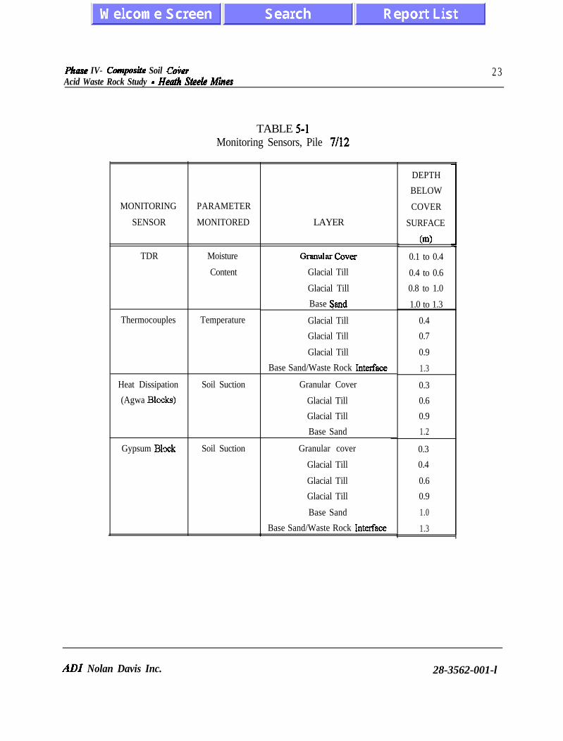
During construction, sensors were installed by NTC within the composite soil cover to measure soilmoisture content, temperature and matric potential (soil suction). The instrumentation was installedin the till layer, the granular cover and the sand base at two locations on top of the waste rock pile.A summary of the sensors and depth location below the surface of the composite soil cover isprovided in Table 5-1.
ADI Nolan Davis Inc. 28-3562-001-l
Have IV- Covnposit Soil CoierAcid Waste Rock Study - Heatk Steeh! Mimes
2 3
TABLE 5-lMonitoring Sensors, Pile 702
MONITORING
SENSOR
TDR
Thermocouples
Heat Dissipation
(Agwa Blccks)
Gypsum Blxk
PARAMETER
MONITORED
Moisture
Content
Temperature
Soil Suction
Soil Suction
LAYER
Granular coverGlacial Till
Glacial Till
Base Sand
Glacial Till
Glacial Till
Glacial Till
Base Sand/Waste Rock Interface
Granular Cover
Glacial Till
Glacial Till
Base Sand
Granular cover
Glacial Till
Glacial Till
Glacial Till
Base Sand
Base Sand/Waste Rock Interface
DEPTH
BELOW
COVER
SURFACE
(ml
0.1 to 0.4
0.4 to 0.6
0.8 to 1.0
1.0 to 1.3
0.4
0.7
0.9
1.3
0.3
0.6
0.9
1.2
0.3
0.4
0.6
0.9
1.0
1.3
ADI Nolan Davis Inc. 28-3562-001-l

_ .
f%se IV- Composite Soil Co&rAcid Waste ROCR Study - Heath Steele Mines
24
5.3.1 Soil Moisture Content
The soil moisture content of the glacial till cover is measured using Time-Domain Reflectometry(TDR). TDR is a radar technique in which a fast rise time voltage pulse is propagated through thesoil and its reflection measured. The pulse is guided through the soil by stainless-steel rods of knowndimensions. The measurement of travel time (At) yields an estimate of “apparent” dielectric constant(K,) of the soil. The volumetric soil-moisture content (0,) is then calculated using a relationdeveloped by Topp et al. (1980), or other soil-specific relations. The TDR transmission lines werefabricated by NTC, based on a three-rod design. The rods were 30 cm long in the sand layers and20 cm long in the till. The probes were placed in each layer horizontally as the cover was beingconstructed. The application of the voltage pulse and measurement of At were performed with aTektronix 1502B TDR metallic cable tester.
The moisture sensors were calibrated by NTC during installation. As an additional calibration checkthe field moisture content results were compared to the in-situ moisture content measurements asdetermined by AD1 Nolan Davis with a nuclear density gauge and found to be in agreement.
5.3.2 Temperature
Thermocouples, similar to the type K previously placed in the waste rock, were also installedthroughout the cover to measure the temperature in each of the cover materials.
5.3.3 Soil Suction
Soil suction is measured by heat dissipation and electrical resistance, with both methods measuringa specific physical property of an absorbent or a porous block in equilibrium with the soil of interest.From these measurements, matric (or pressure) potential produced from the soil-water capillaryforces is determined. Soil suction, being the negative of mat& potential, is defined in terms of thesoil phase and is therefore a positive number. It is generally expressed as pressure (kPa or bars) orhydraulic head (metres of water or pF).
A heat-dissipation sensor measures the rate at which heat dissipates in a porous ceramic block. Thedevelopment of the sensor is presented in Rahardjo et al. (1989). A sensor based on a designdeveloped by Phene et al. (1971), which consists of a miniature heater and a thermocouple encasedin a porous ceramic block, was adapted for the soil cover. The thermal conductivity of the ceramicblock is sensitive to itswater content and can be related to soil suction. The temperature of the blockis measured before and after a known quantity of heat is delivered to the block. More heat willdissipate through the block at higher water contents, resulting in a smaller increase in temperature(AT). Ifthe soil loses water and the suction increases, then the water content of the sensor decreases
ADI Nolan Davis Inc. 28-3562-001-l

Pkose IV - Composite Soil boiwAcid Waste Rock Study - Heath Steele Mimes
2 5
and AT increases. Consequently, AT is proportional to the soil suction. Where each sensor is uniquein its relation to soil suction, calibration is required prior to installation. Calibration proceduressimilar to those presented Fredlund and Wong (1989) were followed.
An electrical-resistance sensor, commonly composed of gypsum (Bouyoucous and Mick 1940),measures the electrical resistance of an absorbent block, . Resistance is sensitive to the water contentof the block; high water contents yield low resistance. When the block is in contact with soil, theelectrical resistance varies inversely with soil suction. Electrical resistance, however, also varies withpore water chemistry. Gypsum is used for two reasons: (i) its relatively low solubility contributes tothe longevity of the sensors, and (ii) a saturated solution containing Ca2’ and SOq2- ions provideseffective bufl?ering at low PH. As a result, the variance of the resistance of a gypsum block, resultingfrom the small changes in soil chemistry, has less significance than that of a block composed of aninert material. In general, individual gypsum blocks have similar response to soil suction; thereforea generalized calibration provided by the manufacturer was used.
Four heat-dissipation sensors were installed at each monitoring station, one in each sand layer andtwo in the till; and six gypsum blocks were installed, one in each sand-till contact. All sensors wereinstalled as each lift was placed. Following compaction, a small-diameter (25mm) hole was augered,the sensor installed in a soil slurry, and the hole backfilled and sealed to the surface with bentonite.
5.4 Meteorological Data
A fully operational meteorological station was established on Pile 7/12 in June 1992. The stationrecords rainfall, evaporation, temperature, relative humidity and wind on a continuous basis.
5.5 Automated Monitoring System
An automated monitoring system was installed on Pile 7/12 to collect and store the large volumes ofdata generated by the sensors. The system consists of two Campbell Scientific data loggers, ModelCRlO, with three Campbell Scientific multiplexers. The three multiplexers consists of two AM416’sfor soil suction and thermocouple sensors and one SDMXSO for TDR probes. The data acquisitionsystem was programmed to record data from the sensors at regular time intervals, varying fromhourly to daily readings.
Meteorological data from the weather station is also recorded and stored in the dataloggers.
5.6 Collection System - Seepage Through Cover
Two lysimeters, which were installed directly beneath the composite soil cover, collected the seepage
ADI Nolan Davis Inc. 28-3562-001-l

R4a.w IV- Composite Soil CoverAcid Waste ROCR Sr~d& - Heatk Steele Mimes
2 6
through the cover above the lysimeters. The water collected was then drained to the base of the pileand into a dedicated coilection chamber inside the outfall structure. This connection was made viaa 50 mm PVC pipe installed underneath the composite soil cover along the north face of the pile.
A drain was installed in the center of the pile at the base. The water reaching the perimeter ditchwhich is located .at the intersection of the composite soil cover with the Fabrene membrane at the baseof the pile, is directed to a collecting drain connected to the outfall structure.
5.7 Instrumentation Monitoring Equipment Summary
A summary of the instrumentation either installed in waste rock Pile 7/12 or used to monitorperformance is summarized in Table 5-2.
Additional details on instrumentation and monitoring of waste rock piles is presented in the FieldProcedures Manual prepared as part of MEND project 1.22.1 a.
ADI Nolan Davis Inc. 28-3562-001-l

Phase IV- Composite Soil CoverAcid Waste Rock Study - Heath Steele Miies
27
TABLE 5-2Instrumentation, qile 7/12
METHOD
Cover and Pile Parameters
Soil suction (1) Heatdissipation sensors
(2) Electrical-resistance sensors (gypsum blocks)
Moisture content Time-domain reflectometty (TDR)
Gaseous oxygen and CO,Portable oxygen and CO, meters in conjunction with permanently emplaced samplingtubes
Temperature Thermocouple sensors
Seepage through cover Two collection-basin lysimeters, each 2.0 x 3.1 m, 6.2 m2 surface area, 9.8 m3 volume,semicylindrical, acid-resistant, high-density polyethylene
Water Quality Outflow collection and laboratory analysis:
(i) Lysimeters (seepage through the cover)
(ii) Pile perimeter dram (pile runoff, through the cover’s granular base above the wasterock)
(iii) Pile base (seepage through the cover and the pile)_ _
Meteorological ParsPnneters
Rainfall Tipping-bucket rain gauge
Evaporation U.S. Class A evaporation pan
Air temperature Thermistor sensors
Relative humidity Surface resistivity (of impervious solid) sensor
Wind speed Three-cup anemometer
Automated nionitorhg system
Parameters measured Soil suction, moisture content, soil and air temperatute, relative humidity, wind, rainfall,and pan evaporation
Data acquisition Two Campbell Scientific, model CR10 dataloggers
Three Campbell Scientific multiplexers: AM4 16 multiplexer for soil suction sensors,AM416 multiplexer for thermocouple sensors, and SDMXSO multiplexer for TDRprobes
TDR measutement Tektronix 1502B TDR metallic cable tester
Data retrieval Computer modem or direct connection
Power 12Vdc(110Vacsource)
ADI Nolan Davis Inc. 28-3562-001-l

Phase IV - Composite Soil CoGerAcid Waste Rtxk Srudy - Heath Steele Mines
28
6.0 MONITORING RJCSULTS
The performance of the composite soil cover on Pile 7/12 was monitored on a continuous basis sinceSeptember 1991. Pile 18B, the control pile, was also monitored over the same period in conjunctionwith Pile 7/12.
The monitoring results, to October 1993 and prehminary interpretation are presented in the followingsections. Additional monitoring details are presented in Appendix IV.
6.1 Gaseous Oxygen
The oxygen concentrations measure& since 1991 for Piles 7/12 and 18B are summarized in TablesIV-1 and IV-2 respectively of Appendix Iv and shown graphically over time in Figures IV-1 to IV-12for each of the monitoring stations. The results of oxygen concentration measurements to October1993 indicate that:
l Prior to placement of the cover, oxygen concentrations in Pile 7/12 ranged from 3.2 to20.8 percent.
l Oxygen levels near the surface of the pile are particularly influenced by the weather(decreasing in the winter).
l In the summer as temperatures in the pile increase, thermal convection of oxygen into thepile causes oxygen levels to increase.
0 After cover placement in September 1991, there was a dramatic decrease in oxygenconcentrations throughout Pile 7/12.
l Oxygen concentrations within the pile as of October 1993 were measured at less than 1percent. 1
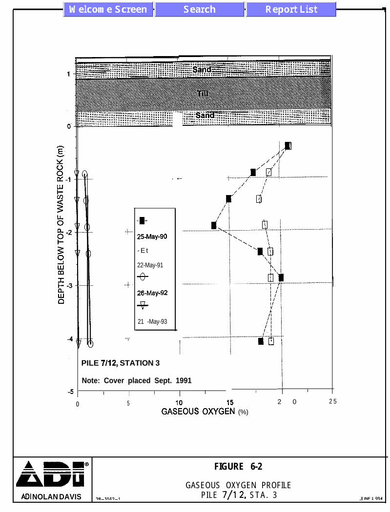
The magnitude of the change in oxygen concentration before and after the placement of the cover isillustrated on Figures 6-l and 6-2, where the range of oxygen concentrations within the pile has beenplotted from May 1989 to October 1993. It is apparent from Figures 6-1 and 6-2 that the mostsignificant decrease in oxygen occurred within several months after cover placement.
The oxygen concentrations measured in Pile 18B exhibit a cycle that is mainly dependent of theclimatic conditions, and to a lesser extent, the oxidation rate of the waste rock.
ADI Nolan Davis Inc. 28-3562-001-l

II--l-I(o/o) N
39AX
O S
flO3S
W9
---q
A
mm
@FIG
URE 6-1
GASEO
US OXYG
EN vs. TIME
ADJ NOJANDAVE
PILE 7/12, STA.3
0
.+.
..$. .
“‘I’
-I-25May-90
- E t
22-May-91
-e-
26-May-92
+
21 -May-93
. i... .j...
PILE 7/12, STATION 3
Note: Cover placed Sept. 1991I I I I I
ADI NOLAN DAVIS
I/mn/
/Y/ /i
_.._.._.____ r:‘d..; _...____......____..................../ I ;
/ I/
/ /IdI
I I
5&O”S ox&l (%)
2 0 2 5
FIGURE 6-2
GASEOUS OXYGEN PROFILEPILE 7/l Z’, STA. 3 .I1 INF 1 WI4
Phase IV- Campsite Soil Co+erAcid Waste Rock Study - Heath Steele Mimes
31
6.2 Temperature.
The measured temperatures for Piles 7112 and 18B are summarized in Tables IV-3 and IV-4 ofAppendix IV and shown graphically in Figures IV-13 to IV-25. The results of temperaturemonitoring to October, 1993 indicate that:
0 Prior to the placement of the cover, high temperatures were noted which are indicativeof the existence of the endothermic oxidation process.
l Temperature decreases were evident in Pile 7/12 within one month after cover placement.l A direct correlation between temperatures and weather conditions exists.
The magnitude of the temperature changes prior to and after cover placement is illustrated in Figures6-3 and 6-4, which shows the range of temperature measured since May 1989 to October 1993. Themost significant decrease in temperature occurred within several months after cover placement.Temperatures throughout Pile 7/12 are still decreasing, but at a much reduced rate.
6.3 Gaseous CO,
Gaseous CO, concentration measurements were initiated in November 1993 for both piles 7/12 and18B. Tables IV-5 and IV-6 of Appendix IV sumarize the CO, measurements obtained for Pile 7/12and 18B respectively. Although the amount of data collected to date is limited the CO,concentrations indicate that the covered Pile 7/12 has much higher concentration values than theuncovered Pile 18B. The high CO, concentration values inside the covered pile indicate a lack ofoxygenation and aeration reaching the pore spaces of the waste rock, which corroborate with thegaseous oxygen concentration measurements.
6.4 Seepage Through Cover
With the completion of the composite soil cover in September, 1991 Pile 7/12 became a closedsystem. By design, any moisture which enters the system by seepage through the soil cover iscollected either in one of the two lysimeters (northeast lysimeter and northwest lysimeter), theperimeter ditch at the base of the pile (perimeter drain) or a collection drain which extends into themiddle of Pile 7/12 (centre drain) and flows to the outfall structure. A summary of the volumecollected from the collection system is presented in Table 6-1. In the two years since coverplacement, a total of about 1000 litres has been recovered from the four sources, of which 193.6 litreshas been collected from the lysimeters. The volume collected in the two lysimeters represents theseepage through the cover in the area underlain by the two lysimeters only. The water collected fromthe two lysimeters has not come in contact with waste rock and hence is not considered AMD.
ADI Nolan Davis Inc. 28-3562-001-l

40
30
20
10
0
-10
Placement of coverSeptember l&1991
Jan-94Jul-88 Jan-89 JuC89 Jan-90 Jul-90 Jan-91 Jul-91
1 1989 ,+ 1990 + 1991 ~+ 1992 + 1993 +

- 50
. . . .._.... .j ._........................... . . . . i... _...... . . . . . . . . . . . . . . . . . . :I’
! ;
mi \I \I
:
f,.___......._. . . . . ., . . . . . . . . .
. . . . . . . . . . . . . . . J . . . . . . . . . . ..II
I1I. . . . . . . ..-. .I. ..-- . . . . .
liTI
PILE 7/12,‘STATlONNote: Cover placed Sept.II I I I I I I1 I I I I I
\. .!.L,. . . . . . . . . . . . . . . . . . . . .
\\\\\ \
\\\\\
.” .-...... -.---.
I I I I
-I-25-May-90
-El-
22-May-91nv
26-May-92
+
21-May-93
’ I. . . . . . . ..-.... _ . . . . . . . . . . k . . ..)..............................I
iII
I
L
5 10 15 2 0 2 5 3 0
TEMPERATURE (“C)
ADI NOLAN DAVIS 28-3562-l
FIGURE 6-4
TEMPERATURE PROFILEPILE 7/12, S T A . 3 JUNE 199,

Phase IV- Composite Soil Co;erAcid Waste Rock St&y - Heath Steele Mimes
3 4
TABLE 6-lDischarged Quantities
Outfall Structure
CENTRE PERIMETER NORTHEAST NORTHWEST
DATE DRAIN DRAIN LYSIMETER LYSIMETER
(litre) , (lib-e) (litre) ( l i t r e )
1992 50.5 3 86.00 25.95 72.35
1993 65.00 443 .oo 43.10 50.20
TOTAL: 115.50 729.00 69.05 124.55
Rainfall was measured at the HSM site since the installation of the meteorological station in 1992.The results of rainfall measurement over selected periods along with volume of seepage collected inthe two lysiieters, are presented in Table 6-2. The results of measurements to date indicate that lessthan 2 percent of precipitation infiltrates through the cover to the waste rock.
TABLE 6-2Rainfallbsimeter Measurements. Pile 7/12
EQUIVALENT INFILTRATION
DEPTH VOLUME’ VOLUME
DATZ (=I w-e) (like) RATIO
June 24 - August 18,1992 198 2455.2 50.3 2.0%
May 21 -July 13,1993 188 2331.2 20 0.9%
January - December, 1993 1118.9” 13 875 100 0.7%
Note: * Tota l aer ia l surface of lysimeters=l2.4 square metre* * Average annual precip i ta t ion
ADI Nolan Davis Inc. 28-3562-001-I

Phase IV- Composite Soil CoGerAcid Waste Rock Study - Heath Steele Mines
3 5
6.5 Leachate Quality
The water collected from both the centre and perimeter drains has come in contact with the wasterock and hence is considered as leachate. The total volume of leachate collected in the outfallstructure over the two year study period is a combination of both leachate trapped within the pile attime of cover placement which has now moved through the system plus any seepage which has passedthrough the composite soil cover and then moved through the encapsulated waste rock to the onlydischarge point at the outfall structure,
The results of analytical testing of leachate recovered from the base of Pile 7/12 are summarized inTable 6-3. Tables IV:7 and IV+8 of Appendix IV provide additional details of leachate testing. Thedata presented shows no significant change in water quality before and after construction of thecover. Table 6-3 indicates that there has been a noticeable increase in pH since placement of coverbut in terms of leachate loadings, there is no significant change in water quality before and afterconstruction of the cover.
TABLE 6-3Leachate Wate r Qua l i ty “- a1Centre Drain, Pile 7/12
July 1989 - Ott 1990 1 9 9 2 1993
PH 2.1 - 2.8 2.3 - 2.9 3.0 - 3.2
Acidity (CaCO,) mg/L 15 800 - 73 250 15 800 - 54 450 Not Available
Sulphate (mg/L) 12 700 - 43 440 5 140 - 71042 9 970 - 73 854
Dissolved Iron ’ 3 510 - 13 767 15 800 - 54 000 5 000 - 30 844
ADI Nolan Davis Inc. 28-3562-001-l

Phase IV - Composite Soil CoiwAcid Waste Rock Study - Heath Steele Mines
3 6
6.5.1 Soil Suction
The results of the soil suction or matrix potential measurements from the gypsum blocks arepresented in Table 6-4 for three separate monitoring events namely fall of 1991 and the spring andsummer of 1992. The results to date indicate that the matrix potential of the lower section of theglacial till and base sand are stable, which is indicative of a consistent moisture content. Variationsin the soil suction measurements of the granular cover and upper glacial till are consistent with thevariations in moisture content due to wetting and drying which would be expected to occur in thesezones. Additional details on soil suction measurements are presented in Appendix IV, Figures IV-26and IV-27 for the heat dissipation sensors, and in Figures IV-28 and IV-29 for the gypsum blocks.
TABLE 6-4Soil Suction
Gypsum Block Method, Pile 7/12
MATRIC POTENTIAL &Pa)91/10/31 92/05/3 1 92108126
LAYER West East West East West Eastb Granular Glacial GF;izjl Till Cover (Top (Bottom 200 200 mm) mm)30 10 10 10 10 10 10 10 20 60 30 30 40 20 20 30 100 20 20 30 30 20 20 30
ADI Nolan Davis Inc. 28-3562-001-l

Phase IV - Composite Seil Co&Acid Waste Rock Study -Heath Steele Mimes
3 7
6.5.2 Moisture Content
Monitoring of the moi,&ure colitent of the various layers in the composite soil cover by TDR indicatethat the cover is performing as designed with the volumetric moisture contents in the glacial till andsand base showing little change from those taken immediately after cover placement. Table 6-5summarizes volumetric mois+re content measurements for three separate periods, namely fall 1991and spring and summer, 1992.
I LAYER
TABLE 6-5Volumqtric Moisture Content
TDR Method, Pile 702
VOLUMETRIC MOISTURE! CONTENT (%)91/10/31 92/05/3 1 92/08/26
West East West East West East
Note: N.A.= Not Available
12 8 8 7 9 83 0 3 2 2 5 30 N.A. 3 634 30 27 26 3 1 301 2 1 2 1 12 11 1 13 1 2
ADI Nolan Davis Inc. 28-3562-001-l

pkose IV- Composite Soil Co&r 3 8Acid Waste Rock Study -’ Heath Steek Mimes
7.0
1)
2)
3)
4)
5)
CONCLUSIO;vS
The composite soil cover was successfully placed on waste rock Pile 7/12 betweenAugust 28 and September 17, 1991 by Atco Construction of Newcastle, N.B.Observations recorded during cover placement and the results of quality controltesting, indicate the cover was constructed in accordance with the design proposedby NTC using local materials.
The petiormance monitoring of the covered waste rock pile 7/12 after the cover wasplaced indicates that the composite soil cover is an effective way to reduce the impactof acid generating waste rock. The placement of the cover has resulted in a depletionof oxygen within the pile as well as a reduction in pile temperatures. This reductionin both oxygen and temperature is interpreted as an indication that the oxidationprocess within Pile 7/12 has been severely reduced.
While Pile 7/12 is small compared with many waste rock piles elsewhere, the resultsof this study show potential for utilizing composite covers as an effective managementapproach for larger waste rock piles. It should be noted that despite the performanceof the cover, a low volume of AMD is still being discharged from Pile 7/12 and mustbe treated before discharge to the environment.
Performance monitoring of the glacial till layer indicates that it has maintained itsmoisture content at the level at which it was placed after two years. Seepage throughthe cover has been measured at less than 2 percent of total precipitation which isconsistent for a soil having a hydraulic conductivity of less than 1 x lo-’ cm/set.
The total cost ofcover construction in 1991 was $60,000 (Cdn), or about $22.50/m*of cover placed. For larger waste rock piles, this unit cost would be expected todecrease. The cost for engineering and construction quality control is not includedin those costs because of the research nature of the project.
ALU Nolan Davis Inc, 28-3562-001-l

Phse IV- Composite Soil CoPerAcid Waste Rock Study - Heat% Steele Mimes
39 .
8.0 REFERENCES
Bell, A.V. 1988, Acid waste rock management at Canada Base Metal Mines ProceedingsInternational Conference on Control of Environmental Problems from Base Metal Mines,Norway.
Bell, A.V., Riley, M.D., YanfX, E.K, 1994. Evaluation of a composite soil cover to control acidwaste rock pile drainage. International Land Reclamation and Mine Drainage Conference andthe Third International Conference on the Abatement of Acidic Drainage, Pittsburgh, PA,April 24-29, 1994.
Bennett, J.W.; J.R. Harries; and A.I.M. Ritchie, 1988. Rehabilitation of waste rock dumps at theRum Jungle mine site. p. 104-108. Proceedings of Mine Drainage and Surface MineReclamation.
Boutoucous, G.J., and Mick, AH. 1940. An electrical resistance method for continuous measurementof soil moisture under field conditions. Michigan Agricultural Experiment Station, TechnicalBulletin No. 172.
Ferniuk, N., and M.D. Haug, 1990. Evaluation of in situ permeability testing methods. ASCEGeotech Eng. 116(2):297-3 11.
Fredlund, D.G., and Wong, D.K.H. 1989. Calibration of thermal conductivity sensors for measuringsoil suction. CIotechnical Testing Journal, 12(3): 188-194.
Harries, J.R. and A.I.M. Ritchie, 1981. The use of temperature profiles to estimate the pyritic ironoxidation rate in a waste rock dump from an open cut mine. Water, Air and Soil Pollution16:405-423.
Harries, J.R and ALM. Ritchie, 1985. Pore gas composition in waste rock dumps undergoing pyriticoxidation. Soil Sci. 140:143-152.
Harries, J.R and A1.M. Ritchie, 1987. The effect of rehabilitation on the rate of oxidation of pyritein a mine waste rock dump. Environ Geochem and Health 9(2):27-36.
MEND Project 2.3 1. la. 1992. Heath Steele Waste Rock Study, Phase 1 to 3. March 1992.
Nolan, Davis & Associates. 1987. Study of acid waste rock management at Canadian base metalmines. Report to Energy, Mines and Resources Canada (UNMET), Ottawa.
ADI Nolan Davis Inc. 28-3562-001-l

Phase IV- CompoSae Sil C&rAcid Waste Rock Study -Heath Steele Miies
40
Nolan, Davis & Associates. 1990. Heath Steele Waste Rock Study, Phase II Report. Report toBrunswick Mining and Smelting Corporation Limited.
Nolan, Davis & Associates. 1993. Field Procedures Manual, Gas Transfer Measurements, WasteRock Piles, Heath Steele Mines. Report to Energy, Mines and Resources Canada(CANMET), MEND Project 1.22. la, Ottawa.
Phene, C.J., Hoffman, G.H., and Rawlins, S.L. 1971. Measuring soil matric potential in situ bysensing heat dissipation within a porous body: 1. Theory and sensor construction. SoilScience Society of America, Proceedings, 35: 27-33.
Rahardjo, H., Loi, J., and Fredlund, D.G. 1989. Typical matric suction measurements in thelaboratory and the field using thermal conductivity sensors. Proceedings of the IndianGeotechnical Conference, 14-16 Dec. 1989. Visakhapatnam, India. Vol. 1, pp. 127-131.
Topp, G.C., Davis, S.L. 1985. Time domain reflectometry (TDR) and its application to irrigationscheduling. In Advances in irrigation. Vol. 3. Academic Press, Inc., New York, pp. 107-127.
YanfU, E.K., Bell, A.V., Woyshner, M.R, 1993. Design of a composite soil cover for anexperimental waste rock pile near Newcastle, N.B., Canada. Canadian Geotechnicai Journal,Vol. 30, pp. 578-587.
YanfUl, E.K., Riley, M.D., Woyshner, M.R., Duncan, J., 1993. Construction and monitoring of acomposite soil cover for an experimental waste rock pile near Newcastle, N.B., Canada.Canadian Geotechnical Journal, Vol. 30, pp. 588-599.
Zegelin, S.J., and I. White (1989). Improved field probes for soil water content and electricalconductivity measurement using time domain reflectometry. Water Resour. Res.25( 11):2367-2376.
ADI Nolan Davis Inc. 28-3562-001-l

APPENDIX I
Project Specifications

COMPOSITE SOIL COVER
HEATH STEELE MINES
NEWCASTLE, N.B.
Request for Proposal
August, 1991

August 7, 1991
Gentlemen:
You are invited to provide a proposal for the supply of all labour, supervision, .tools andequipment necessary for placement of a composite soil cover over waste rock Pile 7/12. Thescope of work is outlined in the enclosed specification package and engineering drawings.
Heath Steele Mines will assign a representative to oversee the work and maintain qualitycontrol on a full time basis. Initial surveying and grade control will also be provided by HeathSteele Mines. It must be emphasized that for this project, because of the nature of the work,any deviation from the quality control requirements without the approval of the Project Directorwill be unacceptable.
All work must be completed to the satisfaction of our representative on site. Yourproposal is to be directed to the Project Director, Mr. Jim Duncan and is required by August 16,1991 at 2:OO p.m. An information session with all invited contractors will be held August 9, 1990at 10~00 at Heath Steele Mines. Project to start immediately upon issuance of Purchase Order.
Sincerely,
James DuncanProject Director

Composite Soil Cover -Heath Steel MinesNewcastle, N.B.
Price Proposal
Page 1 of 2
Following Schedule of Prices does not constitute part of official contract but must becompleted and submitted in Contractors proposal. Prices indicated will form basis for PurchaseOrder which will be issued upon award of contract.
Contractor shall complete following Schedule of Prices for placement of a composite soilliner in Waste Pile 7/12. Description of work may be found in the specifications. Prices quotedshall include the supply of all materials, plant, tools, labour and equipment necessary to carry outand properly complete cover placement and associated tasks to satisfaction of Project Director.Quantities shown on the Schedule of Prices are approximate and are subject to change.
Contractor also to provide rental rates for all equipment to be used in installation ofcomposite soil cover. Also include standby rates and charges for delay. Work will be measuredup monthly and contractor will prepare progress claims based on these measurements.
The lowest or any price proposal will not necessarily be accepted. Heath Steele Minesreserves the right to select the contractor of his choice.

Composite Soil Cover -Heath Steel MinesNewcastle, N.B.
Price Proposal
Page 2 of 2
SectionN O .
Item
0200 * Borrow Source Lump Sum 1
0 2 1 0 SurfacePreparation
0 2 2 0 Sand Base
0 2 3 0 ImpermeableCover
0 2 4 0 GranularCover
0 2 5 0 ErosionProtection
0 3 0 0 LeachateCollection
Outfall Structure100 mm Drain
0 4 0 0 InstrumentationLysimeter
Schedule of Prices
Unit of Price PerMeasurement Unit
EstimatedTotalQuantity‘
EstimatedTotal .Price
tonne 100
hours
Lump Sum
Lump Sum
4 0
700 In3
1500 ma
Lump Sum
tonne
1000 ma
7 5 0
Lump SumMetre
18 0
Lump Sum 2
Estimated Total

Composite Soil Cover- Spkication IndexHeath Steel Mines andNewcastle, N.B. List of Drawing
Index
Page 1 of 1
Section
0 1 0 0
0 1 1 0
0200
0210
0 2 2 0
0 2 3 0
0 2 4 0
0250
0 2 6
0 3 0
0 4 0
Appendix I
Appendix II
Appendix III
Appendix IV
Appendix V
Drawing No.
F-91 -057-l
F-91 -057-2
F-01-057-3
Description
General Instructions
Environmental Protection
Borrow Source
Surface Preparation
Sand Base
Impermeable Cover
Granular Cover
Erosion Protection
Site Grading
Leachate Collection
Instrumentation
Workman’s Compensation
Strike or Lockouts
Insurance
Safety Regulations
Workplace Hazardous MaterialsInformation System
Description
Site Plan
Construction Details
Instrumentation Details
Number of Pages
3
1
2
2
2
5
2
1
1
3
3
1
1
2
2
1
&J&
August 1991
August 1991
August 1991

Composite Soil CoverHeath Steel MinesNewcastle, N.B.
General Instructions Section 0100
Page 1 of 3
1 . 1 General .I Work under this contract is divided into descriptive sectionswhich are not intended to identify absolute contractuallimits. Contractor- shall be responsible for organizingdivision of iabour and supply of material and equipmentessential to complete project in all its parts as establishedin articles of agreement.
.2 Work described in this section of specifications, includes,but is not restricted to requirements for setting outprocedures, project administration, safety and protection ofproperty and people. It shall apply to work of all sectionsof specifications.
.3 All work subject to approval of Project Director of HeathSteele Mines.
1.2 Description of Work .l Work under this contract shall consist of placement of acomposite soil cover on waste rock pile, known as Pile 7/12,at Heath Steele Mines. Composite soil cover comprises ofa 60 cm thick impermeable soil layer sandwiched betweentwo 30 cm thick granular layers complete with necessarymonitoring instrumentation and other work related thereto.
.2 Supply and installation of leachate collection andmonitoring instrumentation to waste rock pile, site gradingand construction of surface drainage to sedimentation pondon site and other work related thereto.
1.3 Site Lay Out .l Engineer will provide only those survey control points andset one (1) bench mark and set such stakes as necessary todefine general location, alignment and elevation ofsuccessive cover layers. Give Engineer reasonable noticeof requirements for such control points and stakes.
.2 Set grades and lay out work in detail from control pointsand grade established by Engineer.
.3 Assume full responsibility for and execute complete layoutof work to locations, line and elevations indicated.

Composite Soil CoverHeath Steel MinesNewcastle, N.B.
General Instructions Section 0100
Page 2 of 3
A Supply stakes and other survey markers required for layingout work.
1.4 Fami l ia r iza t ion .lwith site
Invited contractors shall have one of his principals examinesite and ensure that all possible factors concerningearthwork are investigated and that following are known inparticular
.l Methods and means available for material handling,disposal, storage and transportation.
.2 Physical conditions of site, including existingmonitoring equipment, and drainage courses.
.3 Configuration and conditions of ground surfaces
.2 No allowance will be made by Heath Steele Mines fordifficulties encountered or expenses incurred on account ofany site condition, or any growth or item existing thereon.
.3 Prior to submission of proposals an information session willbe held on site with Project Director and Project Engineerto discuss project requirements.
.4 Invited Contractor responsible for identifying localconditions and any other factors which may affect hisproposal and performance of work.
1.5 Work Schedu le .l In conjunction with, and in form acceptable to ProjectDirector, provide with proposal a schedule showing datesfor delivery of items of materials and constructionequipment, commencement of work, overall work schedule,and completion dates for each specific task. Schedule shallbe based on scope of work as indicated in specifications andon drawings.
.2 All work shall bc carried out continuously until completion.All work shall bc completed on or before October 15,199l.
Composite Soil Cover General Instructions Section 0100Heath Steel MinesNewcastle, N.B. Page 3 of 3
.3 Interim reviews of work progress based on schedulesubmitted will be conducted as decided by Project Directorand schedule updated by Contractor in conjunction withProject Director.
1.6 Contractor .l Contractor to provide a list of equipment and tools (type ofResponsibilities equipment, size, etc.) to be used on project to Heath Steele
Mines security upon arrival to mine site.
. .2 Safety hats, footwear, glasses, coveralls, etc. to be suppliedby Contractor. Contractor responsible to ensure that safetyequipment is worn by all its employees.
.3 Contractor responsible for transportation of its employeesto and from work site.
.4 Contractor to supply his own lunchroom and sanitaryfacilities.
1.7 Provision for Traffic .1 Create least interference with traffic consistent with faithfulperformance of work. Contractor should be aware thathaul roads are travelled frequently by heav equipment ofHeath Steele Mines.
.2 Do not close or block roadways unless approved by ProjectDirector.
.3 Provide construction signs, warning signs, lanterns and floodlights required.

Composite Soil Cover -Heath Steel MinesN e w c a s t l e , N . B .
Environmental Protection Section 0110
Page 1 of 1
1.1
1.2
Fires .l
Disposal of Wastes .l
.2
.3
1.3 Drainage .l
.2
.3
1.4 Measurementfor Payment
.l
Fires and burning of rubbish on site will not be permitted.
Do not bury rubbish and waste materials on site unlessapproved by Project Director.
Disposal of waste or volatile materials, such as mineralspirits, oil or paint thinner into waterways, storm or sanitarysewers prohibited.
Containers and waste fluids associated with equipment andvehicle maintenance are to be removed from site anddisposed of at an approved waste disposal site. I
Provide temporary drainage and pumping as necessary tokeep site free from water.
Pumping of water containing silt in suspension inaccordance with local authority requirements.
Control disposal or runoff of water containing suspendedmaterials or other harmful substances in accordance withlocal authority requirements.
No separate measurement to be made under thissection.

Composite Soil CoverHeath Steel MinesNewcastle, N.B.
Borrow Source Section 0200
Page 1 of 2
PART 1 - GENERAL
1.1 Description .l
1.2 Protection .l
1.3 EnvironmentalPermits
.l
1.4 Measurement for .lPayment
.2
PART 2 - EXECUTION
2.1 Clearing andGrubbing
.l
.2
.3
2.2 Removal andDisposal
.l
2.3 Storage of Materials .l
This section specifies requirements for development,operation, and closure of an approved source of glacial tillfor construction of impermeable cover.
Prevent damage to trees, vegetation and natural features,outside outer boundaries of borrow source. Make gooddamage.
Heath Steele Mines will provide necessary permit(s) fordevelopment of borrow source. Contractor responsiblemeeting requirements of local authorities as outlined inpermit(s).
Site development and closure shall be paid as a lump sumand shall include all items specified herein.
Excavation and transportation of glacial till paid underSection 0230.
Cut off tree shrubs, stumps and other vegetation towithin 100 mm of original ground surface.
Grub out stumps and roots to not less than 300 mm belowground surface.
Remove surficial sand and gravel, topsoils and other soilsnot suitable for cover development to top of glacial tilllayer.
Usable timber-becomes property of HeathSteele Mines. Stockpile at locations provided by Owner.
Stockpile in separate areas all grubbed materials and allsoils not suitable for cover development.

Composite Soil CoverHeath Steel MinesNewcastle, N.B.
Borrow Source Section 0200
Page 2 of 2
2.4 B o r r o w S o u r c e .lDevelopment
2.5 Si te Restorat ion .l
2.6 Site Grading
.2
.2
.2
.3
.1
.2
.3
Provide ditching, berms and silt traps as necessary tominimize impact of suspended materials in runoff from site.
Develop borrow source in stages. Clearing andgrubbing limited to area sufficient to meet projectrequirements for glacial till.
Do not stockpile glacial till. Excavate and transport to siteonly material placed during that day of work activity.
Site closure immediately upon completion of impermeablecover.
Place stockpiled site grubbing in borrow pit and grade.
Cover site grubbings with stockpiled soil not suitable forcover development.
Shape restored borrow area to an even grade, infilling alllarge depressions.
Slope back all pit faces in borrow area to minimum 2H:lVslope.
Grade site to .minimize impact of silt laden runoff onenvironment. Provide silt traps as necessary.
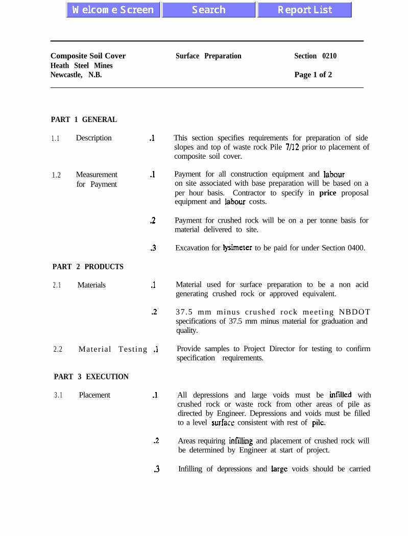
Composite Soil CoverHeath Steel MinesNewcastle, N.B.
Surface Preparation Section 0210
Page 1 of 2
PART 1 GENERAL
1 . 1 Description .l
1.2 Measurementfor Payment
.l
.2
.3 Excavation for Iysimeter to be paid for under Section 0400.
PART 2 PRODUCTS
2 . 1 Materials .1
.2
2.2 Material Testing .1
PART 3 EXECUTION
3 . 1 Placement .l
.2
.3
This section specifies requirements for preparation of sideslopes and top of waste rock Pile 7/12 prior to placement ofcomposite soil cover.
Payment for all construction equipment and labouron site associated with base preparation will be based on aper hour basis. Contractor to specify in price proposalequipment and labour costs.
Payment for crushed rock will be on a per tonne basis formaterial delivered to site.
Material used for surface preparation to be a non acidgenerating crushed rock or approved equivalent.
37.5 mm minus crushed rock meeting NBDOTspecifications of 37.5 mm minus material for graduation andquality.
Provide samples to Project Director for testing to confirmspecification requirements.
All depressions and large voids must be infilled withcrushed rock or waste rock from other areas of pile asdirected by Engineer. Depressions and voids must be filledto a level surface consistent with rest of pile.
Areas requiring infilling and placement of crushed rock willbe determined by Engineer at start of project.
Infilling of depressions and large voids should be carried

Composite Soil CoverHeath Steel MinesNewcastle, N.B.
Surface Preparation Section 0210
Page 2 of 2
3.2 Slope Grading
3.3 Top of WasteRock Pile
.l
.2
.3
.l
.2
out so as to minimize disturbance to existing pile.
Grade high areas on side slope of waste rock pile toconform with overall pile slope. Areas requiring grading tobe identified by Engineer at start of project.
Grading of side slope shall be carried out so as to minimizedisturbance to existing pile.
Remove large size waste rock at base of pile and place asdirected by Engineer.
Lysimeters (Section 0400) to be installed prior topreparation of top of pile surface.
Infill voids and depressions as required by Engineer.

Composite Soil Cover Sand Base Section 0220Heath Steel MinesNewcastle, N.B. Page 1 of 2
PART 1 GENERAL
1.1 Description .l
1.2 Measurementfor Payment
.l
.2
PART 2 PRODUnS
2 . 1 Sand Base .l Sand base material to be non acid generating.
.2
2.2 Material Testing .l
PART 3 EXECUTION
3 . 1 Placement .l
-2
.3
This section specifies requirements for supply andplacement of a sand base for composite soil cover onprepared surface of waste rock Pile 7/12.
Transportation and placement of sand basecomponent of composite soil cover and other workperformed under this section shall be measured forpayment as a lump sum.
Sand for lysimeter installation to be paid for under Section0400.’
Sand should be a well graded medium to coarse grainedmaterial meeting following requirements
.l 60% ranging between 0.5 and 4.0 mm diameter.
.2 Dloranging between 0.35 and 0.40 mm diameter
Provide samples to Engineer for testing to confirmspecification.
Sand base shall be a minimum thickness of 30 cm overentire waste rock pile. Layer thickness may be thicker inlow lying or steeper sloping areas oi pile.
Sand base should be placed in a minimum of two layers.Initial layer of IO-15 cm thick layer placed over preparedbase to provide a smooth surface.
Protect all instrumentation and leachate collection piping

Composite Soil Cover - Sand Bake Section 0220Heath Steel MinesNewcastle, N.B. Page 2 of 2
.4
3.2 Compaction . l
.2
.3
.4
3.3 Finishing .1
.2
.3
3.4 Maintenance .1
during placement of sand base.
Sand base shall placed as directed by Engineer.
Sand base shall be compacted with several passes of amedium size vibratory roller to 92% of its Modified ProctorDensity (ASTM D1557)
Shape and roll alternatively to obtain a smooth anduniformly compacted base.
Apply water as necessary during compaction to obtainspecified density.
In areas not accessible to rolling equipment, compact tospecified density with approved mechanical tampers.
Immediately prior to completion of sand base placement,entire top surface shall be rolled with a smooth cylindricalroller or other equipment as considered appropriate byEngineer so as to leave area in a smooth, even conditionfor drainage. Suitable equipment shall be provided on siteat all times for this purpose.
Finished compacted surface to be flat with surfaceirregularity within f 25 mm of average grade.
Final finished slopes to be at 3H:lV.
Maintain finished surface in a condition conforming to thissection until succeeding impermeable cover placement.

Composite Soil CoverHeath Steel MinesNewcastle, N.B.
Impermeable Cover Section 0230
Page 1 of 5
PART 1 GENERAL
1.1 Description
1.2 Measurementfor Payment
.l
l 2
PART 2 PRODUCTS
2.1 Impermeable Cover .l
.2
.3
This section specifies requirements for supply andplacement of impermeable cover on prepared sand baseover waste rock Pile 7/12
Transportation and placement of impermeable covercomponent of composite soil cover and other workperformed under this section shall be measured forpayment as a lump sum item.
Payment for development and closure of Borrow Source tobe paid under Section 0200.
Impermeable cover material to be non acid generating.
Impermeable cover material to be a glacial till approved byEngineer. Heath Steele Mines have identified anacceptable borrow source on Anderson Road approximately3.2 km from site.
Impermeable cover component of composite soil cover shallmeet following specifications.
.1 Grain Size (ASTM D 422)Maximum particle size of 30 mm,Minimum percent finer than 0.075 mm particle sizeof 40% by dry weightMinimum percent finer than 0.002 mm particle sizeof 10% by dry weight.Dloranging between 0.001 and‘0.003 mm particlesize
.2 Moisture content (ASTM D 2216)-2 to +4% of optimum moisture content

Composite Soil CoverHeath Steel MinesNewcastle, N.B.
Impermeable Cover Section 0230
Page 2 of 5
.3
A
.5
PART 3 EXECUTION
3 . 1 Compaction Equipment .l
3.2 Water Distribution
3.3 Field Test Strip
.l
.2
.l
3.4 Placement .l
.2
Atterberg Limits (ASTM D 4318)Liquid Limit > 30 and Plasticity Index > 15
Moisture Density Relationship (ASTM D 1557)Soil must be capable of reaching 95% of maximumdry Modified Proctor density at a moisture contentof -2 to +4% of optimum.
Hydraulic Conductivity (ASTM D 2434)Coefficient of permeability (K) 1 x 10 - 7 cm/set orless.
Compaction equipment to consist of a mediumweight vibratory compactor or sheepsfoot roller asapproved by Engineer capable of obtaining requireddensities
Water distribution equipment must be capable ofuniform distribution of water over cover.
Water distribution equipment to be present on siteduring entire cover placement operation.
Prior to placement of impermeable cover on wasterock pile, Contractor will construct a field test stripmeasuring 5 m x 10 m in plan using materials,method of placement and compaction techniquesproposed. A minimum of 2 layers to be placed intest strip. Compacted in situ density and hydraulicconductivity to be measured infield.
Final compacted thickness of impermeable cover tobe minimum 60 cm
Impcrmcablc cover to be placed in 20 cm thicklayers spread in a loose slate

Composite Soil CoverHeath Steel MinesNewcastle, N.B.
Impermeable Cover Section 0230
Page 3 of 5
3.5 Compaction
.3 Cover to be placed at moisture content rangingfrom -2 to +4% of optimum.
.4 Contractor shall repair and/or replace materialswhich do not meet specifications and be responsiblefor repair and/or replacement of unsuitable areas onwaste rock pile at no additional cost to HeathSteele Mines.
.5 Protect all instrumentation and leachate collectionpiping during placement of cover.
.l Cover to be compacted with approved compactionequipment as soon as layer graded. Moisture loss tobe kept to a minimum.
.2 Apply water as necessary during compaction tomaintain specified moisture content. If cover isexcessively dried out, remove from site and replace.
.3 Impermeable cover compacted to 95% of its dryModified Proctor density (ASTM D 1557)
.4 Compacted cover layer approved by Engineer priorto placement of successive layer.
.5 Compaction equipment shall pass over impermeablecover a sufficient number of times to maximizecompaction. Each lift shall receive a minimum of 4passes of approved compaction equipment.
.6 In areas not accessible to rolling equipmentincluding around monitoring casing, compact tospecified density with approved mechanical tampers.
.7 During compaction operations turning of equipmentshall be effected carefully to ensure uniformcompaction.

Composite Soil CoverHeatb Steel MinesNewcastle, N.B.
Impermeable Cover Section 0230
Page 4 of 5
.8
3.6 Existing Geomembrane .l
.2
.3
.4
.5
3.7 Final Grade
3 . 8 Weather
.l
.2
.3
.I
.2 Immcdiatcly prior to suspension of impermeable
Glacial till shall be kept free of lenses, pockets,streaks and layers of pervious material.
All tom or deteriorated sections of geomembrane attoe of existing pile, which will no longer retainwater, to be removed.
Tight seal between existing geomembrane andimpermeable cover is imperative.
Place initial layer of impermeable cover onmembrane in areas where competent membraneexists. Turn membrane up into cover before placingnext layer.
Areas where membrane deteriorated leaving it shortof cover, provide additional membrane as directedby Engineer.
Bond between cover and geomembrane to beapproved by Engineer.
Immediately prior to completion of impermeablecover, entire top surface to be rolled with a smoothcylindrical roller or other equipment as considered,appropriate by Engineer so as to leave area in asmooth even condition for drainage.
Finished compacted surface to be flat with surfaceirregularities within + 25 cm of average grade.
Final finished slope to bc at 3H:lV.
Impermeable cover operations shall be suspended asdirected by Engineer whenever climatic conditionsarc unsatisfactory for placement to conform to thisSpecification.
Composite Soil CoverHeath Steel MinesNewcastle, N.B.
Impermeable Cover Section 0230
Page 5 of 5
3.9 Instrumentation
3.10 Maintenance
cover placement, entire top surface shall be rolledwith a smooth cylindrical roller as so to leave areain a smooth, even condition for drainage. Suitableequipment shall be provided on site at all times forthis purpose.
.l Contractor shall make provision for installation ofinstrumentation as required by Heath Steele Mines(Section 0400).
.l Maintain finished surface in a condition conformingto this section until succeeding granular coverplacement.
.2 Apply moisture as required should moisture contentfall below minimum requirements.

Composite Soil CoverHeath Steel MinesNewcastle, N.B.
Granular Cover Section 0240
Page 1 of 2
PART 1 GENERAL
1 . 1 Description .l
1.2 Measurementfor Payment
PART 2 PRODUCTS
2.1 Granular Cover
2.2 Material Testing
.l
.l
.2
.1
This section specifies requirements for supply andplacement of granular cover on completedimpermeable cover over waste rock Pile 7/12
Transportation and placement of granular covercomponent of composite soil cover for waste rockpile and other work performed under this sectionshall be measured for payment as a lump sum item.
Granular cover material to be non acid generating
Granular cover material to be well graded pit runsand and gravel or equivalent crushed rock whichmeets following gradation requirements.
.l Maximum particle size of 50 mm
.2 Maximum percent finer than 0.075 mm sizeof 8% by dry weight
.3 Source of material to be approved byEngineer
Provide samples to Engineer for testing to confirmspecification.
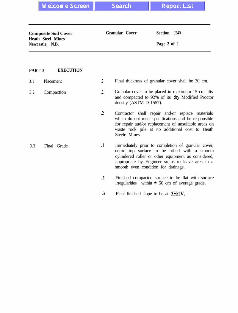
Composite Soil CoverHeath Steel MinesNewcastle, N.B.
Granular Cover Section 0240
Page 2 of 2
PART 3 EXECUTION
3 . 1 Placement
3.2 Compaction
.1
.l
.2
3.3 Final Grade .l
.2
.3
Final thickness of granular cover shall be 30 cm.
Granular cover to be placed in maximum 15 cm liftsand compacted to 92% of its dry Modified Proctordensity (ASTM D 1557).
Contractor shall repair and/or replace materialswhich do not meet specifications and be responsiblefor repair and/or replacement of unsuitable areas onwaste rock pile at no additional cost to HeathSteele Mines.
Immediately prior to completion of granular cover,entire top surface to be rolled with a smoothcylindered roller or other equipment as considered,appropriate by Engineer so as to leave area in asmooth even condition for drainage.
Finished compacted surface to be flat with surfaceirregularities within 2 50 cm of average grade.
Final finished slope to be at 3H:lV.

Composite Soil CoverHeath Steel MinesNewcastle, N.B. -i
Erosion Protection Section 0250
Page 1 of I
GENERAL
1 . 1 Description .l
1.2 Measurementfor Payment
.l
PART 2 PRODUCTS
2.1 Materials . l
.2
PART 3 EXECUTION
3 . 1 Placement .l
.2
.3
3.2 Final Grade .I
.2
This section specifies requirement for supply andplacement of erosion protection layer overcompleted composite soil cover
Payment for all construction equipment and labourassociated with transportation and placement oferosion protection layer of composite soil cover andother work performed under this section shall bemeasured for payment on a per tonne in place basis
Erosion protection component to be a course layerof gravel or equivalent crushed rock having amaximum particle size of 75 mm and 15% by weightfiner than 4.75 mm particle size.
Gravel or crushed rock to be clean, well graded andfree of organic and fines.
Erosion protection layer is to be placed overcompleted composite soil cover to a minimum depthof 10 cm
Placement of erosion layer shall be uniform overwaste rock pile.
Protect all instrumentation and leachate collectionpiping during placement of layer.
Grade side slopes and top of pile to a neatcondition true to line and grade.
Hand finish areas that cannot be finishedsatisfactorily by machine.

Composite Soil CoverHeath Steel MinesNewcastle, N.B.
Site Grading Section 0260
Page 1 of 1
PART 1 GENERAL
1.1 Description .1
1.2 Measurementfor Payment
.l
PART 2 PRODUCTS
2.1 Material .l
PART 3 EXECUTION
3.1 Preparation .1
3.2 Drainage Ditch .l
.2
This section specifies requirements for site gradingincluding requirements for surface drainage control.
Work conducted under this section shall not bemeasured for payment but shall be incidental towork described in Sections 0210, 0220, 0230 0240,0250 and 0300.
Products-to be those on site as deemed appropriateby Engineer.
Grade site within limits of project, eliminatinguneven areas and low spots ensuring positivedrainage. Remove debris, roots, branches, andother deleterious materials. Dispose of removedmaterial as directed.
Construct a drainage ditch(s) as required to directsurface runoff to sedimentation pond on site.
Direction and course of drainage ditch(s) to bedetermined by Engineer.

Composite Soil CoverHeath Steel MinesNewcastle, N.B.
Leachate Collection Section 0300
Page 1 of 3
PART 1 GENERAL
1 . 1 Description .l
1.2 Measurementfor Payment
PART 2 PRODUCYS
2 . 1 Materials
.l
.2
.3
.l
.2
.3
-4
This section specifies requirements for installation ofa leachate collection system, associated piping,and/or other work as deemed appropriate byEngineer for proper completion of work under thissection.
Payment for work conducted under this section willbe measured separate from other sections in thisspecification. Installation and backfill of outfallstructure will be a lump sum item.
Outfall structure and required 50 mm PVC pipingto be provided by Heath Steele Mines.
Payment for 100 mm PVC drain tile to be based onper metre installed.
Fibreglass outfall structure (approximately 0.8 m x1 .O m x 1.8 m) to be fabricated by specialitycontractor. Portals, interior weirs etc. details to befinalized in field.
50 mm PVC pipe and associated traps as percontract construction drawings for leachate piping.
Sand and gravel meeting specification requirementsfor granular cover (Section 0250).
100 mm PVC drain tile.

Composite Soil CoverHeath Steel MinesNewcastle, N.B.
Leachate Collection Section 0300
Page 2 of 3
PART 3 EXECUTION
3 . 1 Collection Piping .l
.2
.3
.4
3.2 Outfall Structure .l
.2
.3
.4
.5
3.3
3.4
Lysimeter Piping
Outlet Piping
.1
.l
.2
Extend existing 50 mm PVC loachate collectionpiping from waste rock pile to new outfall structure.
Install new 50 mm PVC collection piping from toeof waste rock pile on north face near existingleachate collection piping to outfall structure.
All 50 mm PVC collector piping provided withapproved traps.
Provide bentonite seal around area where collectorpiping passes through geomembrane.
Construct 30 cm thick sand and gravel base foroutfall structure. Base to extend 0.5 m outsidedimensions of structure.
Sand and gravel compacted in 15 cm lifts to 95%Modified Proctor density (ASTM 01557).
Elevation of top of sand and gravel base to bedetermined in field by Engineer.
Place fibreglass outfall structure on prepared basein accordance with fabricator requirements.
Backfill around fibreglass structure to top ofstructure with sand and gravel compacted to 95%Modified Proctor density (ASTM D1557).
Install collection piping from lysimeters into outfallstructure as directed by Engineer.
Install 100 mm PVC drain tile at outlet of structure.
Excavate shallow trench to a maximum depth I meastward and southward towards existing

Composite Soil CoverHeath Steel MinesNewcastle, N.B.
Lea&ate Collection Section 0300
Page 3 of 3
sedimentation pond. Length of trench to bedetermined in field based on elevation of outfallstructure.
.3 Provide 15 cm sand base in trench prior to installing100 mm PVC drain tile. Backfill to 15 cm abovedrain with sand. Backfill to surface with excavatedsoil.
.4 Grade surface of trench excavation.
Composite Soil CoverHeath Steel MinesNewcastle, N.B.
Instrumentation Section 0400
Page 1 of 3
PART1 GENERAL
1.1 Description .l
1.2 Measurementfor Payment
.l
.2
.3
A
.5
P A R T 2 PRODUCTS
2 . 1 Materials .l
.2
.3 Bentonite
PART 3 EXECUTION
3 . 1 Existing MonitoringEquipment.
.I
This section specifies requirements for installation ofinstrumentation in waste rock Pile 7/12 andcompleted composite soil cover.
All instrumentation to be provided by NorandaTechnology Centre.
Payment for all construction equipment, labour,sand and gravel required for installation oflysimeters (2) will be based on a lump sum per unitbasis.
There will be no separate payment for delay of lessthan 2 hours at any one time due to placement ofmoisture sensors and pressure transducers inimpermeable cover.
Delay beyond 2 hours at any one time will be at anagreed standby rate.
Heath Steele Mines will provide PVC piping, fittingsand bentonite.
Lysimeters (2), moisture sensors, pressuretransducers and associated wiring.
50 mm PVC piping and associated fittings
Extend existing monitoring casing(s) abovecomposite cover to an elevation approved byEngineer. _
Composite Soil CoverHeath Steel MinesNewcastle, N.B.
Instrumentation Section 0400
Page 2 of 3
3.2 Lysimeters
.2
.l
.2
.3
.4
.5
.6
.7
.8
.9
Protect existing monitoring equipment from anydamage during construction. Make good damage.
Install lysimeters at general locations indicated ondrawings.
Excavate waste rock at locations indicated to aminimum 150 mm below base of lysimeter. Sides ofexcavation to extend a minimum of 300 mm beyondb simeter.
Large voids or depressions in base and side oflysimeter excavation to be infilled with crushed rockor waste rock as outlined in Section 0210.
Prepare base for lysimeter with sand used for sandbase of composite soil cover as outlined in Section0220.
Sand base compacted to 92% of dry ModifiedProctor density.
Surface of sand base to be flat sloping in directionof outfall structure at minimum 2% gradient.
Place lysimeter atop sand base and backfill aroundsides with sand. lnfill lysimeter with sand inaccordance with Noranda Technology Centrerequirements.
Excavate small trench for lysimeter collection pipingin top of waste rock from lysimeter north to sideslops of pile.
Place 150 mm sand bedding in trench prior toplacing 50 mm PVC drain. Backfill to 50 mm abovedrain with sand. Drain from lysimeter installed atminimum 2% gradient.
Composite Soil CoverHeath Steel MinesNekastle, N.B.
Instrumentation Section 0400
Page 3 of 3
.lO
3.3 Moisture Sensors andPressure Transducers
.l
.2
.3
.4
.5
.6
Place 50 mm PVC lysimeter drain pipe on top ofprepared side slope of waste rock pile from top ofwaste rock pile to outfall structure as directed byEngineer.
Moisture sensors and pressure transducers to beinstalled in impermeable cover by personnel fromNoranda Technology Centre.
Sensors and transducers to be installed at base ofimpermeable cover, at top of cover, and at depth of20 and 40 cm. Sensors to be placed as soon asglacial till has been compacted.
Most sensors and transducers w-ill be distributedover top of pile. Several will be installed on one ofside slopes. Locations of all sensors and transducersto be determined in field by Noranda TechnologyCentre.
Wiring for instrumentation will be laid from sensorsand transducers to an existing central monitoringcasing.
Contractor responsible for protection of all wiringextending from instrumentation to centralmonitoring casing.
Impermeable cover material to be placed aroundinstrumentation as directed by Engineer.
x

PA
RT
ICL
E
SIZ
E
DIS
TR
IBU
TIO
N
PR
OJE
CT
N
O.
FSl-0
57
FIG
. N
O.
n-1
PR
OJE
CT
- PHA
SE IV AC
ID W
ASTE R
OC
K STU
DY - C
OM
POSITE SO
K C
OVER
LOC
ATIO
NH
EATH
STEELE MIN
ESD
ATEJU
LY 1991
PE
RC
EN
T FIN
ER
B
Y
WE
IGH
T
8P
o
-
tiiiiiiiiiiii’II
J-
/
J-
-l
--
--
l
I I
PE
RC
EN
T FIN
ER
B
Y
WE
IGH
T
06180
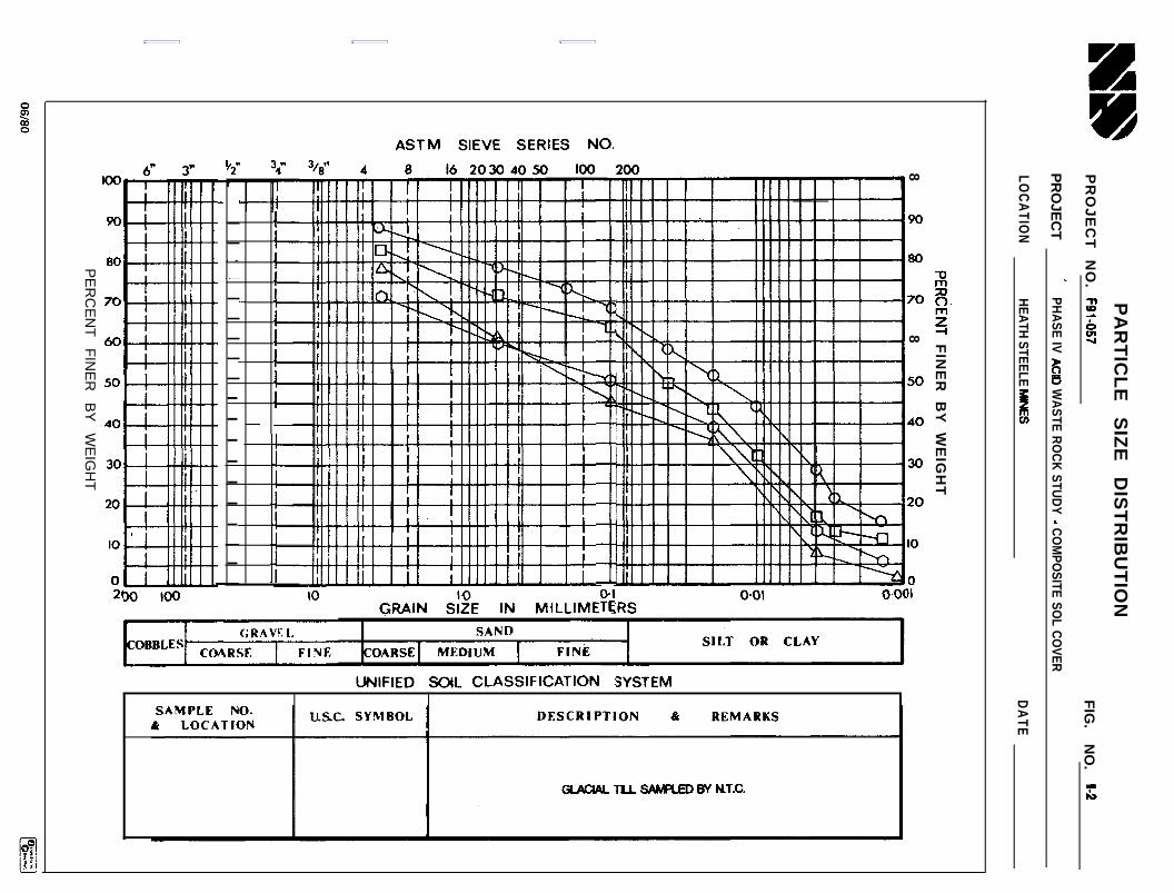
PA
RT
ICL
E
SIZ
E
DIS
TR
IBU
TIO
N
PR
OJ
EC
T
NO
. FQ
l-057F
IG.
NO
. ~-2
PR
OJE
CT
-PH
ASE IV AC30 W
ASTE R
OC
K STU
DY - C
OM
POSITE SO
L CO
VER
LOC
ATIO
NH
EATH
STEELE MIN
ESD
ATE
PERdENT
FIN
ER
B
Y
WE
IGH
T
88
8R
8s
%3
,o0
o=
I 7
wtiiiiiSiim
iiiiiii11
OC
--------------------
---‘---------‘Y
II
II
I3
I I
1 I
I I
I I
I I
I I
I I
I I
I I
1
88
se
8g
9g
R0
06
PE
RC
EN
T FIN
ER
B
Y
WE
IGH
T

PA
RT
ICL
E
SIZ
E
DIS
TR
IBU
TIO
N
PR
OJ
EC
T
NO
. FSl-057
FIG
. N
O.
t-3
PR
OJE
CT
PHA
SE IV AC
ID W
ASTE R
OC
K STU
DY - C
OM
POSITE SO
L CO
VER
LOC
ATIO
NHEATH STEELE MttlES
DATE D
EC
EM
BE
R, 1991
P
PE
RC
EN
T FIN
ER
B
Y
WE
IGH
T
i3b
II
I I
I I
II
II
II
/I/
II
II
II
I I
f
“t-+
++
++
A-ttd
-ttttttttt-tl
tm0
’’
’-a ---
-.-. --t+
Yt--k
--l
gasR
aS
18S
:R
g-~
sP
ER
CE
NT
FINE
R
BY
W
EIG
HT
l-u-l-k

PA
RT
ICL
E
SIZ
E
DIS
TR
IBU
TIO
N
PR
OJE
CT
NO
.F
91-057F
IG. N
O.
b-4
PR
OJE
CT
PH
AS
E IV
ACID W
AS
TE
RO
CK
STUDY
-CoM
poSlT
E so1L
CO
VE
R
LOC
ATIO
NH
EA
TH
ST
EE
LE M
INE
SD
ATE
D
EC
EM
BE
R,
1991
PE
RC
EN
T FIN
ER
B
Y
WE
IGH
T
LA/ 1,
1!
!!’
! -4 KI
! .
. .
. .
..
..
..
PE
RC
EN
T FIN
ER
B
Y
WE
IGH
T
06180

MOISTURE DENSI-W RELATIONSPROJECT NO. F91-057 F I G . N O . n-5
PROJECT PHASE IV AC0 WASTE ROCK STUDY - COMPOSlTE SOL COVER
LOCATION HEATH STEELE MNES DATE SEPTEMBER 1991
18500,5
z 1 8 0 0
10 1 2 1 4 1 8 1 8 20 22
MOISTURE CONTENT (X)
SAMPLE DESCRIPTION
TEST ASTM D 1557
)f d M A X l-S@/-OPT. w. 1 3 . 5 %
GLACIAL TILL

PA
RT
ICL
E
SIZ
E
DIS
TR
IBU
TIO
N
PR
OJE
CT
NO
. m
l-057F
IG. N
O.
I-6 ’
PR
OJE
CT
-PHASE IV A
CID
WA
STE RO
CK
STUD
Y - CO
MPO
SITE soil C
OVER
LOC
ATIO
NH
EATH
STEELE MN
ESD
ATE
SE
PTE
MB
ER
1991
PE
RC
EN
T FIN
ER
B
Y
WE
IGH
T
82?
i3R
ass:8r;,o
o
t
l--.ttt+
++
++
++
+t+
74
---I
t i
i i
i i
i i
i i
iii/i I
LeoG?L*A
-
IM
II
II
I I
II
II
II
II
I I
I‘,
I I
II
II I
I II
I I II
1’1
1 IIIIII lIIII1I
I-1 II
g881?
8g
38R
a”
PE
RC
EN
T FIN
ER
B
Y
WE
IGH
T
06
BO
m

MOISTURE DENSITY RELATIONSP R O J E C T N O . ml-057 FIG. NO. 1-7
PROJECT PHASE IV ACID WASTE ROCK STUDY - COMPOSITE Sow. COVER
LOCATION HEATH STEELE MINES DATE SEPTEMBER 1991
2250
2200
215001f5
2050
3 4 5 8 7 8 9
MOISTURE CONTENT (Z)
SAMPLE DESCRIPTION GRAMARCOVER-SHAoDKmLAKE
TEST ASTM 01557
&d MAX 2240 kg/m3OPT. w. 8.5
APPENDIX III
In Situ Density Test Results

PILE: South Side,East End, Top of Slope
PILE: South Side,West End, Midslope
7 PILE: South Side, silty 18.1 1880 96 Sept. 4191Midpile, Midslope Clayey
First Slope TILL
8 PILE: South Side, Si l ty 18.6 1906 97 Sept. 4191East End, Midslope Clayey
First Lift TILL
9 PILE: South Side, S i l t y 17.9 1908 97 Sept. 4191East End, Top of Slope Clayey
First Lift TILL
10 PILE: South Side, Si l ty 18.4 1926 98 Sept. 4191West End,Top of Slope, Clayey
First Lift TILL
11 PILE: South Side, Si l ty 17.5 1866 95 Sept. 4191Midpile, Top of Slope Clayey
First Lift TILL
12 PILE: South Side, Si l ty 16.4 1893 9 6 Sept. 4191Midpile, Bottom of Clayey
Slope, First Lift TILL
13 PILE: South Side, w 17.1 1872 95 Sept. 4191Midpile, Bottom of ClayeySlope, First Slope TILL
14 PILE: South Side Si l ty 1 6 . 5 1864 95 Sept. 4191East End, Midslope Clayey
First Lift TILL
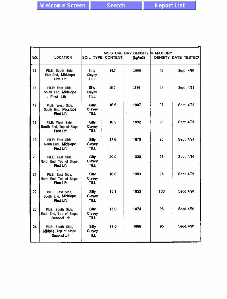
MOISTURE DRY DENSITY % MAX DRYUO. LOCATION SOIL TYPE CONTENT (kglm3) DENSITY DATE TESTEC
15 PILE: South Side, Si l ty 16.7 1695 97 Sept. 4191East End, Midslope Clayey
First Lift TILL
16 PILE: East Side, silty 16.0 1886 96 Sept. 4191South End, Midslope Clayey
. First Lift TILL
PILE: West Side,South End, Midslope
PILE: West Side,South End, Top of Slope
PILE: East Side,North End, Midslope
PILE: East Side,North End, Top of Slope
PILE: East Side,North End, Top of Slope
PILE: East Side,South End, Midslope
PILE: South Side,East End, Top of Slope,
PILE: South Side,Midpile, Top of Slope
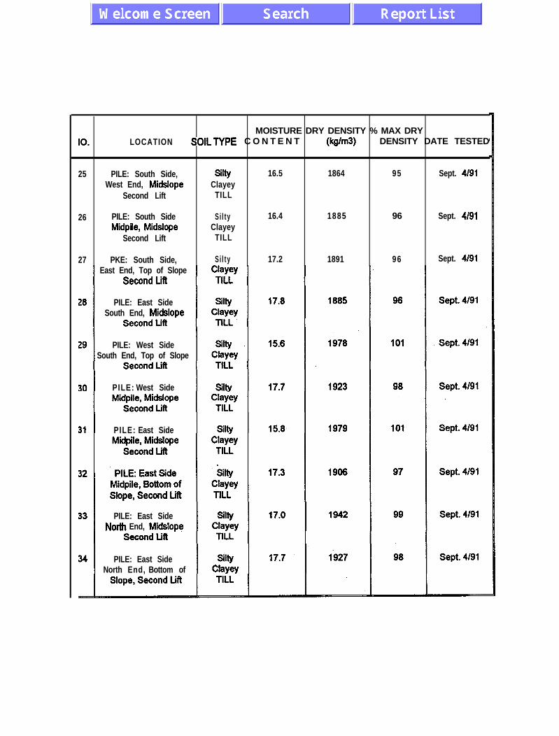
MOISTURE DRY DENSITY % MAX DRYIO. LOCATION SOILTYPE C O N T E N T (WW DENSITY DATE TESTED
25 PILE: South Side, =Y 16.5 1864 95 Sept. 4191West End, Midslope Clayey
Second Lift TILL
26 PILE: South Side Si l ty 16.4 1885 96 Sept. 4191Midpile, Midslope Clayey
Second Lift TILL
27 PKE: South Side, Si l ty 17.2 1891 96 Sept. 4191East End, Top of Slope
PILE: East SideSouth End, Midslope
PILE: West SideSouth End, Top of Slope
PILE: West Side
PILE: East Side
PILE: East SideNorth End, Midslope
PILE: East SideNorth End, Bottom of

MOISTURE DRY DENSITY % MAX DRYJO. LOCATION SOIL TYPE CONTENT ( WW DENSITY DATE TESTED
35 PILE: East Side, Silty 14.7 1962 100 Sept. 4191North End, Midslope Clayey
Second Lift TILL
36 PILE: East Side, Si l ty 15.4 1947 99 Sept. 4191South End, Top of Slope, Clwf
Second Lift TILL
37 PILE: East Side, Si l ty 16.4 1887 96 Sept. 4191South End, Midslope,
PILE: South SideEast End, Top of Slope
PILE: South SideMidpile, Top of Slope,
PILE: South Side,West End, Top of Slope,
PILE: South Side,West End, Bottom of
PILE: South Side,Midpile, Bottom of
Slope(retest)Third Lift
PILE: South Side,

MOISTURE DRY DENSITY % MAX DRYJO. LOCATION SOIL TYPE CONTENT NW) DENSITY DATE TESTED
45 PILE: South Side, silty 17.9 1903 97 Sept. 4191East End, Top of Slope Clayey
Third Lift TILL
46 PILE: West Side, Si l ty 18.7 1850 94 Sept. 4191South End, Top of Clayey
Slope, Third Lift TILL
47 PILE: West Side, Si l ty 17.7 1852 94 Sept. 4191Midpile, Top of Slope
PILE: West Side,North End, Bottom of
PILE: West Side,North End, Bottom of
PILE: West Side,North End, Top of Slope
Midpile, Midslope,Fortyseven, Third Lift

MOISTURE DRY DENSITY % MAX DRYu o . LOCATION SOIL TYPE CONTENT &NW DENSITY DATE TESTED
55 PILE: Top Si l ty 17.4 1878 98 Sept. 8191Northwest Comer, Clayey
First Lift TILL
56 PILE: North Side, W Y 15.2 1924 98 Sept. 8191West End, Midpile, Clayey
First Lift TILL
57 PILE: North Side, Si l ty 18.7 1920 98 Sept. 8191East Side, Midslope,
Southeast Comer,
PILE: North SideMidpile, Midslope,
PILE: North Side,

MOISTURE DRY DENSITY % MAX DRYUO. LOCATION SOIL TYPE CONTENT &NW DENSITY DATE TESTEC
6 5 PILE: North Side, Silty 1 8 . 4 1895 9 7 Sept. 8191East End, Top of Slope Clayey
Second Lift TILL
6 6 PILE: Top, Silty 1 4 . 7 1908 9 7 Sept. 8191Center of Pile, Clayey
. Third Lift TILL
6 7 PILE: Top, Silty 1 6 . 5 1940 9 9 Sept. 8191South Side, Center
PILE: North Side,West End, Top ofSlope, Second Lift
PILE: North SlopeEast End, Top of Slope
PILE: North Slope,
PILE: North Slope,
PILE: North Side,
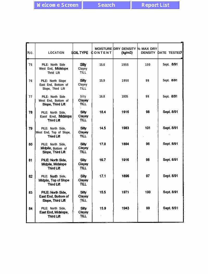
MOISTURE DRY DENSITY % MAX DRYJ O . LOCATION SOILTYPE C O N T E N T Wm3) DENSITY DATE TESTED
75 PILE: North Side =Y 15.6 1955 100 Sept. 6191West End, Midslope Clayey
Thrid Lift TILL
76 PILE: North Slope silty 15.9 1950 99 Sept. 8191East End, Bottom of Clayey
Slope, Third Lift TILL
77 PILE: North Side Si l ty 16.8 1935 99 Sept. 8191West End, Bottom of
PILE: North Side,East End, Midslope
PILE: North Side,West End, Top of Slope,
PILE: North Side,Midpile, Bottom of
PILE: North Side,
PILE: North Side,

MOISTURE DRY DENSITY % MAX DRY40. LOCATION SOIL TYPE CONTENT Wm3) DENSITY DATE TESTED
85 PILE: North Side, Silty 15.5 1 9 3 9 99 Sept. 8191East End, Top of Slope, Clayey
Third Lift TILL
86 PILE: North Side, SilV 18.5 1880 96 Sept. 8191
Midpile Top of Slope, ClayeyThird Lift TILL
87 PILE: North Side, Silty 17.2 1915 98 Sept. 8191
PILE: North Side,
PILE: South Side,West End, Midslope,
PILE: South Side,Midpile, Midslope,
PILE: South Side,East End, Midslope,
PILE: East Side,South End, Top of Slope,
PILE: East Side,
PILE: East Side,
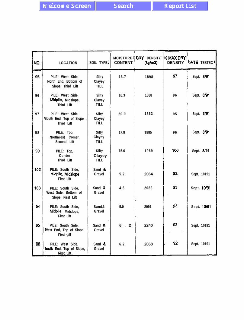
UO.
-
95
96
97
98
104
105
106
LOCATION
PILE: West Side,North End, Bottom of
Slope, Third Lift
PILE: West Side,Midpile, Midslope,
Third Lift
PILE: West Side,South End, Top of Slope
Third Lift
PILE: Top,Northwest Comer,
Second Lift
PILE: Top,Center
Third Lift
PILE: South Side,Midpile, Midslope
First Lift
PILE: South Side,West Side, Bottom of
Slope, First Lift
PILE: South Side,Midpile, Midslope,
First Lift
PILE: South Side,West End, Top of Slope
First till
PILE: West Side,jouth End, Top of Slope,
First Lift
SOIL TYPE
Si l tyClayey
TILL
Si l tyClayey
TILL
Si l tyClayey
TILL
Si l tyClayey
TILL
Si l tyClayey
TILL
Sand &Gravel
Sand &Gravel
Sand&Gravel
Sand &Gravel
Sand &Gravel
MOISTURECONTENT
16.7
16.3
20.0
17.8
15.6
5.2
4.6
5.0
6 . 2
6.2
)RY DENSITY(kg/W
1898
1888
1863
1885
1969
2064
2083
2091
2240
2068
I/oMAXDRYDENSITY
96
95
96
IATE TESTEC
Sept. 8191
Sept. 8191
Sept. 8191
Sept. 8191
Sept. 8191
Sept. 10191
Sept. 10191
Sept. 10191
Sept. 10191
Sept. 10191

MOISTURE DRY DENSITY 016 MAX DRYNO. LOCATION SOIL TYPE CONTENT (WW DENSITY DATE TESTED
107 PILE: West Side, Sand & 6.2 2068 92 Sept. 13191Midpile, Midslope, Gravel
First Slope
108 PILE: West Side, Sand & 6.2 2090 93 Sept. 13191North End, Bottom of Gravel
Slope, First Lift
109 PILE: West Side, Sand & 6.4 2094 94 Sept. 13191South End, Bottom of
Slope, Second Lift
PILE:WestSide,
PILE: East Side,
PILE: East Side,
PILE: East Side,South End, Bottom of
PILE: East Side,North End, Bottom of
Slope, Second Lift
PILE: East Side,Midpile, Top of Slope,

APPENDIX IV
Monitoring Data

FIGURE IV- 1 HEATH STEELE MINES ACID WASTE ROCK
OXYGEN DATA - SITE: 7112, STA: 1
May-90 SepQO Jan-91 May-Q? SepQl Jan-92 May-92 Sep92 Jan-93 May-93 Sep93 DATE
DEPTH
+ 1.4m +Zi- OSm * 0.4m U NA -NA --8-M *NA
-
HEATH STEELE MINES ACID WASTE ROCK OXYGEN DATA - SITE: 7/l 2, STA: 2
0
May-Q0 SepSO Jan-91 May-91 Sap91 Jan-92 May-92 sep92 Jan-93 May-93 SepD DATE
DEPTH
+ 3.9m + 2.4m m l.Sm + 1.4m + 0.9m -8- 0.4m +-+ NA
FIGURE IV-2
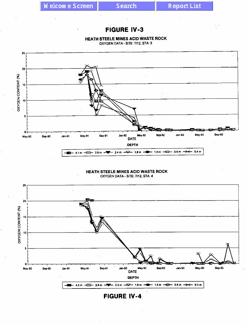
FIGURE IV-3 HEATH STEELE MINES ACID WASTE ROCK
OXYGEN DATA - SITE: 7112, STA: 3
25
SepQO Jan-Q1 May-Q1 Jan-Q2 May-Q2 Sepsz Jan-Q3 May-Q3 SepQ3 DATE
DEPTH
e 4.1 m e 2.9 m W 2.4 m U 1.9 m W 1.4 m -8- 0.Q m * 0.4 m
HEATH STEELE MINES ACID WASTE ROCK OXYGEN DATA - SITE: 7112, STA: 4
25
Sepso Jan-Q1 May-Q1 SepQ1 Jan-Q2 May-02 sepQ2 Jan-03 May-93 sepQ3 DATE
DEPTH
+ 4.3 m a 2.8m + 2.3 m --tiL 1.8 m e 1.3 m -8- 0.8 m --SC 0.3m
FIGURE IV-4 -

FIGURE IV45 HEATH STEELE MINES ACID WASTE ROCK
OXYGEN DATA - SITE: 7112, STA: 5
May-90 Sap90 Jan-91 May-91 SepQl Jan-92 May-92 SepQ2 Jan-93 May-93 SepQ3 DATE
DEPTH
+ 3.7m -E+ 2.3m -f- 1.7m U 1.2m * 0.7m * O.Zm * NA I
HEATH STEELE MINES ACID WASTE ROCK OXYGEN DATA - SITE: 7112. STA: 6
25
0
May-90 sepso Jan-91 May-91 SepQl Jan-92 May-92 Sep92 Jan-93 May-93 Sep93 DATE
DEPTH
+ 2.1 m -E3- 0.6m - 0.1 m -B- NA -m-NA +NA *NA
FIGURE IV-6 -

FIGURE IV-7
- HEATH STEELE MINES ACID WASTE ROCK OXYGEN DATA - SITE: 188. STA: 1
20
5
0 lll,lll,l.~l~~~l~~~l~‘~l~~~l~‘~l~~’)~~”~’~
May-90 Sep90 Jan-91 May-91 Sep91 Jan-92 May-92 Sep92 Jan-93 May-93 Sep93 DATE
DEPTH
+ 3.2m -E!- 2.6m F 2.0m U 1.4m e 0.8m + 0.2m W N4 ---
HEATH STEELE MINES ACID WASTE ROCK OXYGEN DATA - SITE: 188, STA: 2
25
20
5
0
May-90 Sep90 Jan-91 May-91 Sep91 Jan-92 May-92 Sep92 Jan-93 May-93 Sep93 DATE
DEPTH
-I- 4.6m a 4,Om W 3.4m U 2.7m e 2.im -8- 1.5m W 0.9m
FIGURE IV-8

FIGURE IV-9
HEATH STEELE MINES ACID WASTE ROCK OXYGEN DATA - SITE: 188, STA: 3
25
20
5
0 ,,,,,1,,111,1’11~~~‘~‘~‘~~~‘~~~‘~~”~’~’~~~
hby-QO SepQO Jan-91 May-91 SepQl Jan-92 May-92 Sep92 Jan-93 May-93 Sep93 DATE
DEPTH
+ 4.6 m -Ef 4.0177 -f- 3.4 m U 2.7 m e 2.1 m +3- 1.5 m * 0.0 m
HEATH STEELE MINES ACID WASTE ROCK OXYGEN DATA - SITE: 188, STA: 4
Mily-90 SepQO Jan-91 May-91 SepQl Jan-92 May-Q2 S%pQ2 Jan-Q3 May-Q3 SepQ3 DATE
DEPTH
+ 4.6 m -S- 4.0 m * 3.4 m U 2.7m e 2.1 m -43- 1.5 m * 0.6 m ~ I
FIGURE IV- IO

FIGURE IV-1 1
HEATH STEELE MINES ACID WASTE ROCK OXYGEN DATA - SITE: 188, STA: 5
ot I,,, I I,, ( , ( , , , , , , , , I I I I I, I I I , I I I ( I, 1 ,,,,/ May-90 Sep90 Jan-91 May-91 Sep91 Jan-92 May-92 Sep92 Jan-93
DATE May-93 Sep.93
DEPTH
+ 3.7m -Et- 3.lm + 2.5m U 1.9m -C- 1.2m * O.Bm +M+ 0.im
HEATH STEELE MINES ACID WASTE ROCK OXYGEN DATA - SITE: 18B, STA: 8
0
May-90 SepQO Jan-91 May-91 SepQl Jan-92 May-92 SepQ2 Jan-Q3 May-93 SepQ3 DATE
DEPTH
+ 4.3m -B- 3.7m -f- 3.0m e 2.4m e l.Sm -8- 1.2m * O.Bm
FIGURE IV-1 2

FIGURE IV-I 3 HEATH STEELE.MlNES ACID WASTE ROCK
TEMPERATURE DATA - SITE: 7112. STA: 1
50
45
40
35
o^ O- 30
2 3 25
$ 20
I 15
r 10
5
0
-5 ’ ’ , , , , , , , , , , , , , , , , , , ,, , , , , , I, I,, , , , ( , , ) , ) , I May-90 W-J Jan-91 May-91 Sep91 Jan-92 May-92 Sap92 Jan-93 May-93 Sep93
DATE
DEPTH
HEA d-i STEELE MINES ACID WASTE ROCK TEMPERATURE DATA - SITE: 7112. STA: 2
35
5
-5
May-90 Sep90 Jaw91 May-91 Sap91 Jan-92 May-92 Sep92 Jan-93 May-93 Sep93 DATE
DEPTH
+ 0.0m -B- 0.3m W 0.9m -B- 3.9m 6 NA * NA W NA
FIGURE IV- 14

FIGURE IV-1 5 HEATH STEELE MINES ACID WASTE ROCK
TEMPERATURE DATA - SITE: 7112. STA: 3
-5
May-90 Sop99 Jan-91 May-91 JIM2 May-92 sep92 Jan.93 May-93 Sep93 DATE
DEPTH
-I- 0.0 m e 0.4 m + 1.4 m u 4.1 m e NA -e-NA +-+N4
HEATH STEELE MINES ACID WASTE ROCK TEMPERATURE DATA - SITE: 7/12, STA: 4
-5 I ’
May-90 -P90 Jan-91 Jan-91 May-91 Sep91 Sep91 Jan-92 May-92 -P= Jan-93 May-93 Sep93 DATE
Jan-92 May-92 -P= Jan-93 May-93 Sep93 DATE
DEPTH DEPTH
~--I-O.Om-E-O.3m~1.3mU4.3m~NA -8-M *I44 ~--I-O.Om-E-O.3m~1.3mU4.3m~NA -8-M *I44
FIGURE IV-1 6

FIGURE IV-I 7 HEATH STEELE MINES ACID WASTE ROCK
TEMPERATURE DATA - SITE: l/12, STA: 5
--
45
40
35
30
25
20
15
10
5
0
-5
May-80 Jan-91 May-91 sepor Jtlll-92 May92 sep-82 Jan-93 May-93 DATE
DEPTH
+ 0.0 m * 0.2m + 0.7 m U 3.7m e NA *NA +e-NA
sop93
HEATH STEELE MINES ACID WASTE ROCK TEMPERATURE DATA - SITE: 7/12. STA: 6
Jan-92 w-m -PQ2 Jan-B3 Mop93 sops3 DATE
DEPTH
I +O.Om*NA C-0.4m*Z.Om-&NA --4-w GM+ w1
FIGURE IV- 18

FIGURE IV- 19 HEATH STEELE MINES ACID WASTE ROCK
TEMPERATURE DATA - SITE: 7/l 2. STA: 7
DEPTH
I O.Om -iS- 0.7m e O.Om U O.Om e NA * NA +4+ NA
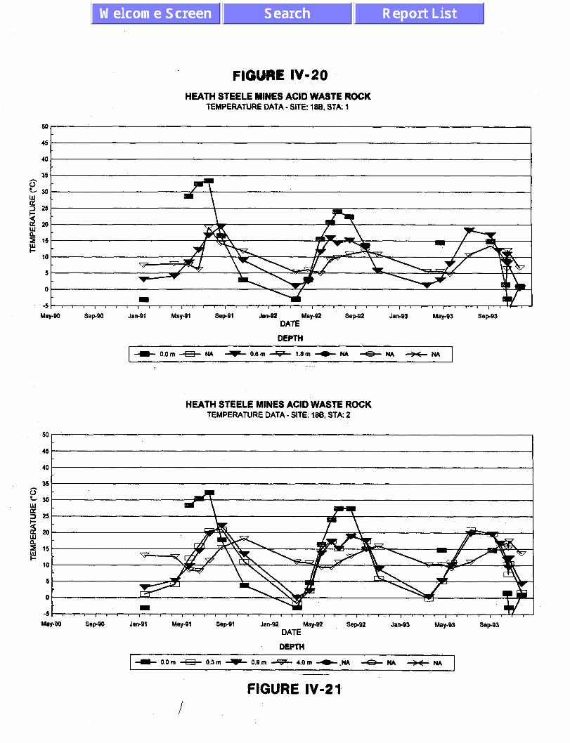
HEATH STEELE MINES ACID WASTE ROCK TEMPERATURE DATA - SITE: 188. STA: 1
40
5
SepeO Jan-91 May-91 SepSl Jan-92 May-92 DATE
DEPTH
SepS2 May-93 Sep93
HEATH STEELE MINES ACID WASTE ROCK TEMPERATURE DATA - SITE: 188, STA: 2
DATE
DEPTH
+ O.Om -M- 0.3 m a 0.9m & 4.0m b-tu -8- NA +m+. ru 1
FIGURE IV-2 1

FIGURE IV-22 HEATH STEELE MINES ACID WASTE ROCK
TEMPERATURE DATA - SITE: 186, STA: 3
Y c
F!p 5 15 E
5
0
-5
May-90 Se@ Jan-91 May-91 Sep91 Jan-92 May-92 DATE
DEPTH
Sep92 Jan-93 May-93 Sep93
+O.Om~i.Sm~2.8mU4.Sm~NA -8-NA *NA
HEATH STEELE MINES ACID WASTE ROCK TEMPERATURE DATA - SITE: 18B. STA: 4
35
30 w
?i 25
Lip
3 15 I-
10
5
Jan-91 May-91 Sap91 Jan-92 May-92 Sep92 Jan-93 May-93 Sep93 DATE
DEPTH -
+ O.Om * 0.1 m + 1.3m e 4.3m e NA d$%+ NA * tu.4
FIGURE IV- 23

FIGURE IV-24 HEATH STEELE MINES ACID WASTE ROCK
TEMPERATURE DATA - SITE: 188, STA: 5
50, I
45
30
25
20
15
10
5
0
-5
Map30 w-0 Jan-91 SepQl Jan-92 May-92 Sep92 JBll-93 My-93 Sap93 DATE
DEPTH
I + 0.0 m * 0.7m + 1.3m + 4.4 m e NA +NA &NJ
HEATH STEELE MINES ACID WASTE ROCK ’ TEMPERATURE DATA - SITE: IEB, STA: 8
45
40
I m -5 I I I , , I I , I I I, I I I, I I I , 1 I I ,I r I ,I I I, I I , , I I I , I I I
May-90 Sep90 Jan-91 May-91 SepQI Jan-92 May-92 Sep92 Jan-93 May-93 Sep93 DATE ^
DEPTH
+ O.Om + 0.2m + 1.1 m + 4.2m + NA *NA *NA
FIGURE IV-25

SUCTION vs TIME, PILE 7112 HEAT DISSIPATION, PILE 7/12
-5 ’
Dee-92 Dee-92
I
Jan-93 Jan-93
I I I I I I I I
Feb-93 Feb-93 Mar-93 Mar-93 Apr-93 Apr-93 May-93 May-93 Jun-93 Jun-93
TIME TIME
- Bottom Sand Layer - Top Sand Layer

SUCTION vs TIME HEAT DISSIPATION, PILE 7112
20
1 . . . . . . . . . . . . . . . . . -..; . . . . . . . . . . . . . . . . . . . . . . . . . . . . . . . . . . . . ..t . . . . . . . . . . . .._..__._...................~ _._...___._...___
! f
1 0 _..................................... 1. . . . . . . . . . . . . . . . . . . . . . . . . . . . . . . . . . . i . . . . . . . . . . . . . . . . . . . . . . . . . . . . . . . . . . . . . . . I....................................... I......................................
i
f
1
i ! I
1
0 !
. . . . . . . . . . . . . . . . . . . . . . . . . . . . . . . . . . . . i . . . . . . . . . . . . . . . . . . . . . . . . . . . . . . . . .
Dee-92 Jan-93 Feb-93 Mar-93 Apr-93
TIME May-93 Jun-93
-Top Till - Bottom Till 1

r
5
4 I . . . . . . . . . . . . . . . . . . . . . . . . . . . . . . . . . . . . . j.........
SUCTION vs TIME GYPSUM BLOCKS, PILE 702
-a-
. . . . . . .
1
. . . . . . . . . . . . . . . . . . . . .
-
. . . .
. . .
. .
I I I
I t I I I I 4
TIME
. . . . . . . . . . . . . . . . ._. . . .
1 t I
- Bottom Sand - Top Sand I

SUCTION vs TIME GYPSUM BLOCKS, PILE 7112
Dee-92 Jan-93 Feb-93 Mar-93 Apr-93
TIME May-93 Jun-93
A Top Till - Mid. Till - Bottom Till 1

TABLE IV-l GASEOUS OXYGEN (o/o), PILE 7/12 HEATH STEELE MINES
28 Port Depth 91 IO1 M 8 91DWll 91/05/22 91/06/19 QllO7llQ 91/06L!l Q2/03/17 Q2lO4i22 Q2lO5m Q2lO6l2Q Q2lO7ll4 Q2lO8n7
(m)
1 1.40 20.50 20.00 21 .OO IQ.00 15.50 20.50 8.80 0.60 0.60 0.50 0.46 0.80 2 0.50 20.50 20.00 21 .w 18.50 15.00 20.00 8.70 0.30 0.50 0.30 0.40 0.90 3 0.40 m.50 20.80 21 .w 18.20 15.00 19.50 11.50 1.60 0.60 2.50 0.32 1.20 1 3.90 20.50 19.50 19.50 11.00 9.00 11.50 NA NA I.90 0.50 0.29 0.22 2 1 2.40 1 NA 1 15.50 1 18.50 1 13.50 1 10.00 1 9.40 1 NA 1 NA 1 1.60 1 1.10 1 0.39 1 0.80 1 3 1.90 NA 14.50 17.00 17.50 14.00 9.60 NA 0.80 1.40 0.80 0.31 0.60 4 1.40 17.50 15.50 18.50 20.30 12.00 13.50 NA 0.80 1.50 0.85 0.27 1.50 5 0.90 NA 18.50 20.50 20.80 18.50 13.50 NA 1.10 1.30 0.72 0.29 , 0.20 8 0.40 18.00 18.00 20.50 20.80 20.00 12.00 NA 0.80 1.20 0.50 0.21 0.45 1 4.10 NA 18.00 19.00 11.80 9.50 13.00 3.10 0.30 1.20 0.60 0.60 0.45 2 2.90 NA NA 19.00 IO.00 13.20 NA NA NA NA NA NA NA 3 2.40 NA 18.00 19.00 8.10 8.70 ‘11.50 7.00 0.80 1.10 0.60 0.47 . NA 4 1.90 NA 15.50 18.50 11.00 5.00 8.20 4.20 0.60 1.00 0.85 0.42 0.32 5 1.40 NA 16.50 18.00 16.50 13.00 9.50 2.10 1.00 0.90 0.50 0.27 0.20 6 0.90 NA 18.00 19.00 IQ.20 15.00 12.50 1.90 1.70 0.80 0.40 0.25 0.14 7 0.40 NA 18.00 20.90 20.20 20.50 14.50 NA NA NA NA NA NA 1 4.30 NA NA 20.50 20.20 NA NA NA NA NA NA NA NA 2 2.80 NA 19.00 19.00 14.00 11.50 15.00 2.00 0.60 0.90 0.20 0.35 0.15 3 2.30 NA IQ.00 17.50 13.w 10.50 14.50 NA 0.20 0.80 0.30 0.10 0.24 4 1.80 NA 19.W 19.00 13.50 10.50 14.50 1.90 4.40 0.70 0.05 0.09 0.15 5 1.30 NA IQ.00 18.00 13.50 id.50 13.50 2.20 4.80 0.70 0.10 0.29 0.13
, 6 0.80 NA 18.50 18.00 13.00 10.00 12.50 NA 4.80 0.80 2.50 0.36 0.21 7 0.30 NA 19.W 20.00 15.50 NA 12.60 NA 3.30 0.80 2.35 0.21 0.13 1 3.70 NA 20.00 18.50 16.00 12.00 16.00 NA NA NA NA NA NA 2 2.30 NA 20.50 18.50 17.00 12.50 18.00 NA 1.00 0.90 0.50 0.29 0.07
1.70 NA 20.50 20.00 19.50 NA 3 NA NA NA NA NA NA NA 4 1.20 NA 19.00 17.50 18.50 10.50 15.50 NA NA NA 6.80 5.21 0.58 5 0.70 NA 19.00 19.50 IQ.00 11.00 16.00 NA 9.00 0.80 4.10 I.20 2.94 6 0.20 NA 18.50 m.50 IQ.00 12.50 17.50 NA 8.10 1.40 13.00 1.61 13.25 1 2.10 20.80 NA 18.50 18.00 IQ.00 20.50 NA NA 0.70 0.05 0.12 0.15 2 0.80 m.80 NA 18.00 17.50 18.00 20.50 NA NA 0.70 0.05 0.41 0.21 3 0.10 20.80 NA 18.00 17.50 16.00 19.00 NA 5.40 0.50 0.05 0.13 0.18
APPENDIX IV 1 of3 28-3562-001 .l

TABLE IV-1 GASEOUS OXYGEN (%), PILE 7/12 HEATH STEELE MINES
-I Station
1
Port Depth Q2ml26 92/10/14 92/11103 93m3ll9 93lO4l24 9wOs21 93lcwl3 93lO9~10 93/1o/o1 (m)
1 1 1.40 I 0.17 I 0.15 I 0.19 I NA 1 0.35 1 0.41 1 0.13 1 0.10 1 0.10 0.15 0.11 2 0.50 0.07 NA 0.28 0.28 0.13 0.10 0.10
3 0.40 0.12 0.12 0.11 NA NA NA NA NA NA 1 3.90 0.28 0.35 0.33 0.40 0.23 0.13 0.11 0.00 0.20 2 2.40 0.28 0.30 0.28 0.20 0.25 0.08 0.08 0.00 0.10 3 1.90 0.20 0.27 0.21 0.10 0.14 0.07 0.11 0.00 0.80 4 1.40 0.18 0.23 0.18 0.15 0.18 0.08 0.10 0.00 0.10 5 0.90 0.13 0.20 0.18 0.10 0.17 0.08 0.10 0.00 0.10 8 0.40 0.11 0.18 0.14 0.07 0.14 0.07 0.09 0.00 0.00 1 4.10 0.20 1 0.18 1 0.11 1 0.20 1 0.14 1 0.02 1 0.10 1 0.50 1 0.20 2 2.90 NA 1 NA I NA 1 NA 1 NA 1 NA 1 NA 1 NA 1 NA 3 2.40. 0.14 0.29 0.11 0.35 0.11 .0.02 0.08 0.00 0.10 4 1 1.90 I 0.13 0.32 0.20 0.20 0.09 0.02 0.08 0.00 0.00 5 1 1.40 1 0.12 0.35 0.15 0.10 0.08 0.01 0.08 0.00 0.10 8 1 0.90 1 0.11 1 0.28 1 0.11 1 0.08 1 0.08 0.01 I 0.04 0.00 1 0.10 7 1 0.40 1 NA NA 1 NA 1 NA 1 NA NA 1 NA NA 1 NA
3 1.70 1 NA I NA I NA 1 NA 1 NA I NA 1 NA 1 NA 1 NA 4 I.20 5 8 1
0.50 0.20 0.20 0.80 0.20 0.30 8.10 0.20 0.30 8.30 0.20 0.30 NA NA NA
0.50 0.20 0.20 NA NA NA 1.60 7.20 2.30
APPENDIX IV 2of3 28-3582-001 .l
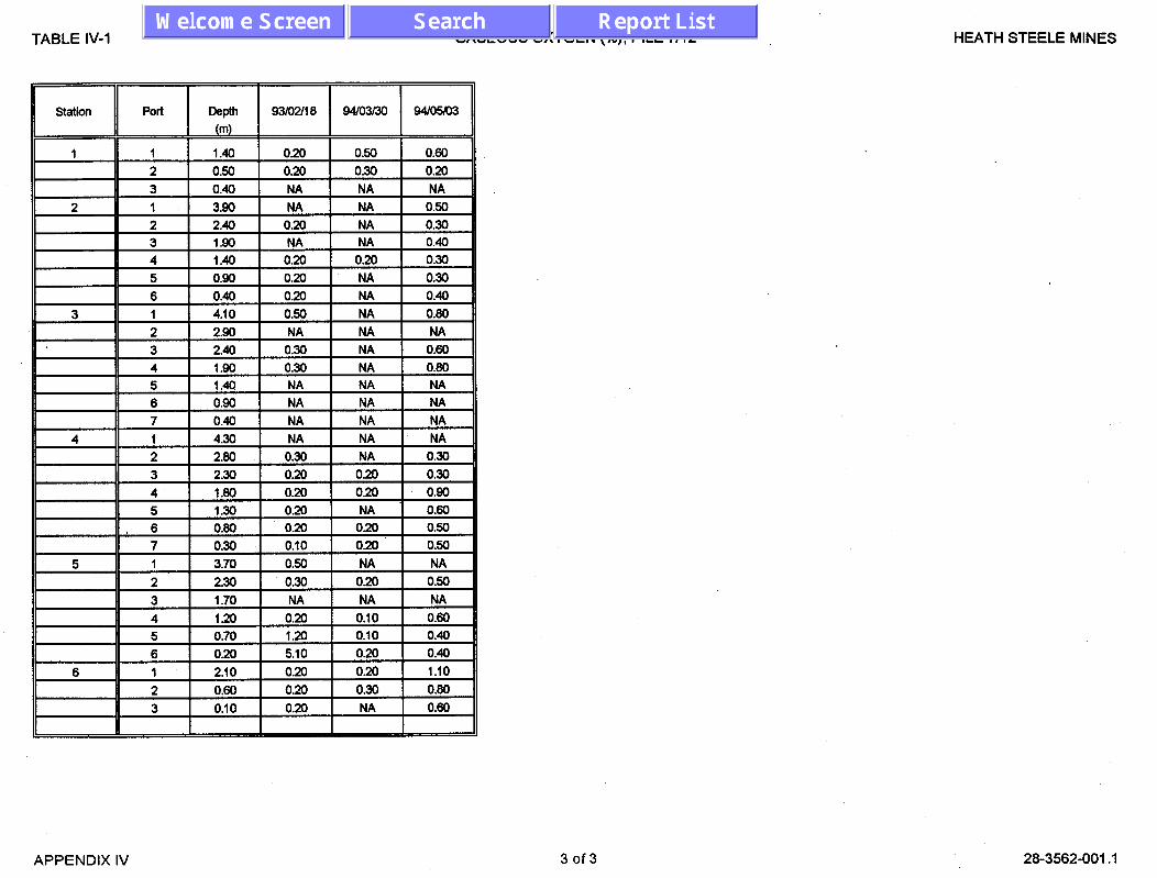
TABLE IV-1 GASEOUS OXYGEN (~1, PILE 7112 HEATH STEELE MINES
APPENDIX IV 3of3 28-3562-001.1
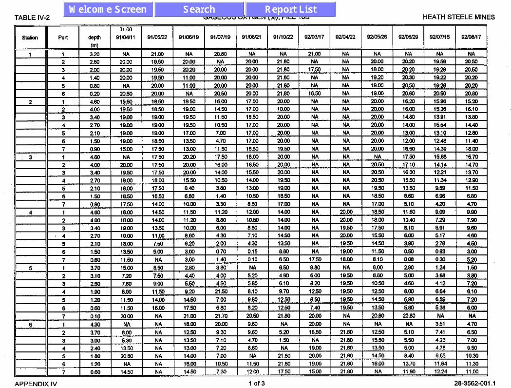
TABLE IV-2 GASEOUS OXYGEN (%), PILE 188 HEATH STEELE MINES
)I Station 11 Port 1 ye I 9fZ1 ) 9l/O51‘22 I 91/06/i~ I 91/07/19 I 91/08/21 ) 9111Of22 I 92/03/17 ) 92/04122 I 92/05126 I ~2/06/29 ) 92/07/15 I 92/08/17 I \“‘, 1 3.20 NA 21.00 NA 20.80 NA NA 21.00 NA NA NA NA NA 2 2.80 20.00 19.50 20.00 NA 20.00 21.80 NA NA 20.00 20.20 19.59 20.50 3 2.00 20.00 19.50 20.20 20.W 20.00 21.80 17.50 NA 18.00 20.20 19.29 20.50 4 1.40 20.00 19.50 11.00 20.00 20.00 21.80 NA NA 19.20 20.30 19.22 20.20 5 0.80 NA 20.00 11.00 20.00 20.00 21.80 NA NA 19.00 2050 19.28 20.20 8 0.20 20.50 20.00 NA 20.50 20.00 21.80 18.50 NA 19.00 20.80 20.50 20.80 1 4.80 19.50 18.50 19.50 18.00 17.50 20.00 NA NA 20.00 18.20 15.98 15.20 2 4.00 19.50 18.50 19.00 14.50 17.00 10.00 NA NA 20.00 18.00 15.28 18.10 3 3.40 19.00 19.00 19.50 11.50 18.50 20.00 NA NA 20.00 14.80 13.91 13.80
APPENDIX IV 1 of3 28-3562-001 .l

TABLE IV-2 GASEOUS OXYGEN (%), PILE 188 HEATH STEELE MINES
APPENDIX IV 2of3 28-3562-001 .l

I-ABLE IV-2 GASEOUS OXYGEN (%), PILE
II sation Port 93.UO/ol 93/11/29 93l12l22 Q4/02/18 Q4lo3t30 Q4m5iO3
1 3.20 NA NA NA NA NA NA
2 2.60 20.80 21.40 20.30 18.70 12.20 20.40 3 2.00 20.80 21.40 20.30 18.70 12.10 20.20
4 1.40 20.80 21.30 20.40 18.80 12.40 20.00
5 0.80 20.80 21.40 20.50 1890 12.00 19.80
6 0.20 21.50 21.60 NA NA NA 19.70
7 0.90 19.30 20.10 19.00 NA NA NA
* ' 1 4.60 16.80 18.30 19.10 15.40 NA 16.80
2 4.00 15.70 18.70 19.10 15.70 NA 17.00
]I 3 1 3.40 1 16.00 1 18.90 1 19.30 ! NA 1 NA 1 17.30
4 2.70 15.80 18.00 19.50 NA NA 17.20
5 2.10 15.20 18.40 19.20 NA NA 16.90
6 1.50 15.80 17.90 NA NA NA 16.70
2 4.00 12.70 17.50 18.50 15.10 11.60 16.50
3 3.40 12.40 17.40 18.90 14.80 12.10 16.40
4 4 2.70 11.50 17.10 18.90 NA NA 16.30
I 5 1 2.10 1 9.70 1 16.20 1 NA 1 NA 1 11.00 1 15.90
1 7 1 0.10 NA 1 NA NA 1 NA 1 NA
1 4.30 4.50 4.40 2.80 16.20 12.70 NA
2 3.70 5.00 8.00 3.10 17.40 12.20 9.00
3 3.00 8.90 14.90 5.90 18.80 13.30 9.60
1 4 1 2.40 1 12.80 1 17.50 1 15.10 1 18.90 1 15.20 1 10.10
5 1.80 12.70 17.50 14.90 18.90 15.20 13.10
6 1.20 15.10 17.90 14.70 18.40 9.40 17.10
7 0.60 17.80 18.20 14.60 17.40 5.30 19.20 ,
HEATH STEELE MINES
APPENDIX IV 3of3 28-3562-00-l .‘I

TABLE IV-3 TEMPERATURE (“C), PILE 7/12 HEATH STEELE MINES
i-l Station Port DEPTH 91/01118 21 .o 91/04/l 1 91/m 91/06/19 91/07/l 7 9llo8n1 91/10/22 92lo317 92m4l22 92lo5lz8 92/07/l 4 92/08/17
APPENDIX IV 1 of2 28-3562-001 .l

TABLE IV-3 TEMPERATURE (“C), PILE 7112 HEATH STEELE MINES
Port
surfaoa Black BllJ8 Red
sulfaca Bkldc Blue
DEPTH (m)
0 NA 0.1 1.4 0
0.3 0.9
92lOQl29 Q2il1103 93/03/l 9 Q3Kw24 93/05/21 93lO7ll3 Q31OQ110 93/l O/O1
13.8 NA NA NA NA NA 15.3 10.1 11.4 NA NA NA NA 7.8 12.3 9.4 13.4 5.8 NA NA NA 13.9 15.3 NA NA 10.9 NA NA NA NA NA NA
14.0 NA NA NA NA NA 15.3 10.1 13.3 8.1 NA NA NA 10.1 13.7 10.7 12.8 8.9 NA NA NA 8.5 12.4 11.5
APPENDIX IV 2 of2 28-3562-001 .l

TABLE IV-4 TEMPERATURE (“C), PILE 18B HEATH STEELE MINES
30.0
Port DEPTH 91/01/16 91104/11 9lhxt22 91/06/19 91/07/17 91/08/21 9l/lOR2 92m3il7 92lo4/22 9sxw28 92ml24 92/07/14
(m)
surfaoa Black
Blue
Red
surfaca
Black
Blue Red
suIfaoa
Black
BlUe
Red
sulfaca
Black
Biua
Red
sulface
Black
Blue
Red
SlItface
Black , Blue
Red
0 -3.1 NA 26.7 32.5 33.4 16.5 3.0 -3.0 3.1 15.5 20.6 24.0 NA NA NA NA NA NA NA NA NA NA NA NA NA
0.6 3.1 4.1 6.3 12.2 16.6 19.4 9.0 1.0 2.5 11.6 15.6 14.2
1.6 7.5 7.9 7.6 6.2 19.1' 14.2 11.9 5.4 6.1 4.9 9.1 9.6
0 -3.1 NA 26.4 30.5 32.3 17.6 3.6 -3.0 4.6 16.4 24.1 27.5
0.3 1.1 4.1 12.2 16.1 20.6 21 .I 11.1 -1.7 2.2 15.1 17.5 15.2
0.9 3.1 5.3 9.7 14.4 19.7 22.2 13.4 0.1 2.1 13.7 172 15.2 4 13.1 12.6 6.5 6.2 11.4 15.5 16.2 11.0 10.7 9.3 9.4 11.0
0 9.1 NA 27.2 34.9 31.6 16.0 4.6 -3.0 5.3 17.7 23.6 ?26.4
1.6 7.6 NA 15.1 12.6 17.3 21.1 16.1 3.5 4.4 11.1 15.3 13.7
2.6 12.3 NA 11.0 9.6 14.3 16.2 19.0 6.3 6.0 6.6 11.7 11.7
4.6 14.2 NA 9.5 8.0 11.0 14.0 17.9 . 11.7 11.0 9.5 9.5 8.4
0 -3.1 NA 21.9 30.6 40.1 15.8 3.8 -3.0 5.4 21.0 19.0 30.5
0.1 0.4 3.6 9.7 20.5 21.9 17.0 7.2 4.3 6.6 15.0 16.9 16.2
1.3 5.2 5.7 9.2 14.1 17.8 21.5 13.8 0.8 3.5 13.7 16.5 15.5
4.3 13.9 11.7 9.5 8.4 11.2 14.9 17.0 10.2 9.5 9.5 9.7 11.4
0 -3.1 NA 25.5 36.0 39.7 17.0 3.8 -3.0 4.4 21.7 21.8 23.9
0.7 4.4 4.6 12.0 16.0 20.4 19.9 10.6 -1.6 1.1 14.0 17.1 16.0
1.3 6.6 5.4 10.9 13.2 17.8 21.2 12.9 0.8 2.6 11.8 16.3 15.4
4.4 13.3 11.2 9.5 7.7 10.0 13.7 15.7 10.2 9.4 8.1 9.4 11.0
0 -3.1 NA 23.5 32.3 37.9 18.0 4.7 -3.0 2.2 19.0 23.6 20.0
0.2 4.7 5.2 NA 13.7 18.9 20.7 11.3 0.8 -0.6 12.5 16.2 15.3
1.1 7.5 7.4 8.6 10.8 15.3 19.2 13.7 2.5 1.3 8.6 13.0 13.5
4.2 11.1 10.8 5.4 6.5 8.6 12.1 13.9 7.8 6.0 7.5 7.6 9.2
APPENDIX IV 1 of3 28-3562-001 .l
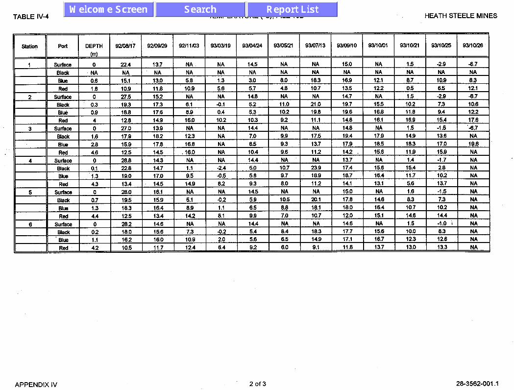
TABLE IV-4 TEMPERATURE (“C), PILE 18B HEATH STEELE MINES El- Station 1 Port DEPTH 92/08/I 7 92m9/29 92lI Ix)3 93lOWI 9 93/o4i24 93/05/21 93/07/l 3 93/09/I 0 93l1om1 93110121 93ilOR5 93kIOl28
(m)
sulfaoe 0 22.4 13.7 NA NA 14.5 NA NA 15.0 NA I .5 -2.9 -6.7 Black NA NA NA NA NA NA NA NA NA NA NA NA NA BlUl? Red 1 I.8 1 IO.9 1 Il.8
APPENDIX IV 2of3 28-3562-001 .l

TABLE IV-4 TEMPERATURE (“C), PILE 18B HEATH STEELE MINES
II station II Poll I DEPTH I 93111119 I 93ll2Q2 I I I 94/02/18 94/0%0 94/06/W
1 It--l sutface 0 1.0 NA NA NA 18.5 Bkk NA NA NA NA NA NA
Red 4.6 13.8 14.9 . NA NA 7.7 surface 0 1.0 NA NA NA 15.8
Bkk 0.1 0.0 2.2 NA 0.2 4.6 Bb ‘1.3 3.2 3.3 NA 0.6 6.1
Red 4.2 1 10.2 1 10.0 1 NA 1 6.6 1 6.2
APPENDIX IV 3 of3 28-3562-001 .l

TABLE IV-5 GASEOUS CO2 (%), PILE 7/12 HEATH STEELE MINES
8tation
1
Depth 93/11/29 93l1222 WO2ll8 94/03/30 94/05/W (m)
1.40 9.98 9.32 10.80 8.49 8.32 0.80 10.18 9.48 10.78 8.32 8.29
Port
1 2 3 0.40 9.42 8.96 NA NA NA
2 1 3.90 11.00 10.!50 NA NA 9.38 2 2.40 9.89 9.38 12.19 NA 9.27 3 1.90 8.49 8.18 NA NA 8.77
3 2.40 * 9.88 9.82 11.88 NA 9.33 * 4 1.90 8.08 7.98 10.85 NA 8.55 5 1.40 7.48 7.42 NA NA NA 8 0.90 7.12 7.12 0.57 NA 8.14
APPENDIX IV 1 of1 28-3562-001 .l

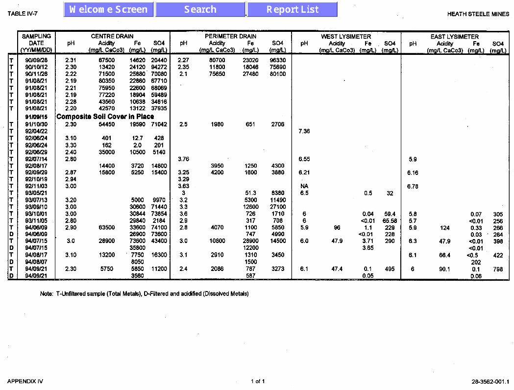
TABLE IV-7 CHEMICAL DATA - SUMMARY HEATH STEELE MINES
;I T T T T T T 1
T T T T 1 T T T T T T T T T T T D T D T D T L
. 22600 68069 18904 59489 10638 34616 13122 37935
0.07 305 co.01 256
0.03 264
<O.Ol
Note: T-Unfiltered sample (Total Metals), D-Filtered and acidified (Dissolved Metals)
APPENDIX IV 1 of 1 28-3562-001.1
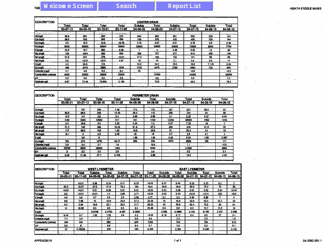
TABLE IV-3 CHEMICAL DATA - DETAJLED HEATH STEELE MINES
DESCRIPTION . CEfUTER DRAIN TOtal Total Total Total Sohrble Total Soluble Total Soluble Total
93-07-13 !&OS-IO 93-10-01 s3-11-0s 04-O&09 944503 94-07-1s 94-07-15 !wOS-15 w-05-15 I I I 1 I I I I I
DESCRIPTICN PERIMETER DRAIN Total Total Total Total Soluble Total Soluble Total Sduble Total
9345-21 w-07-13 934910 93-11-05 944649 94-O&OB 94-07-15 94-07-15 w-OS-15 94-0s15 I I
I DESCRIPTION
APPENDIX IV 23-3562-001 .I

DRAWINGS

L
CP 101
A E 1042.430 N 1069.956
ELEV. 709.52
CP 102 E 1068.7lO N 1015.744
ELEV. 710.27
A
CP 104
A E 1104.264 N 1090.850
2’06.39
CP 103 A
E 1133.155 N 1032.317
ELEV. 709.20
COORDINATES AND ELEVAlloNS ARE BASED ON AN ASSUMED LOCAL GRID.
CONTOUR INTERVAL 2oOmm
g unurf POLE
? INSlRUYENT CLUSTER AND NUMBER
:P 101 A IRON BAR CONTROL POINT k NUMBER
I COMPOSITE SOIL COVER WASTE ROCK PILE 7/12
&-.z*rn By. JAM Checked By:
DotO: JULY 1994 W=t r:F91-057-
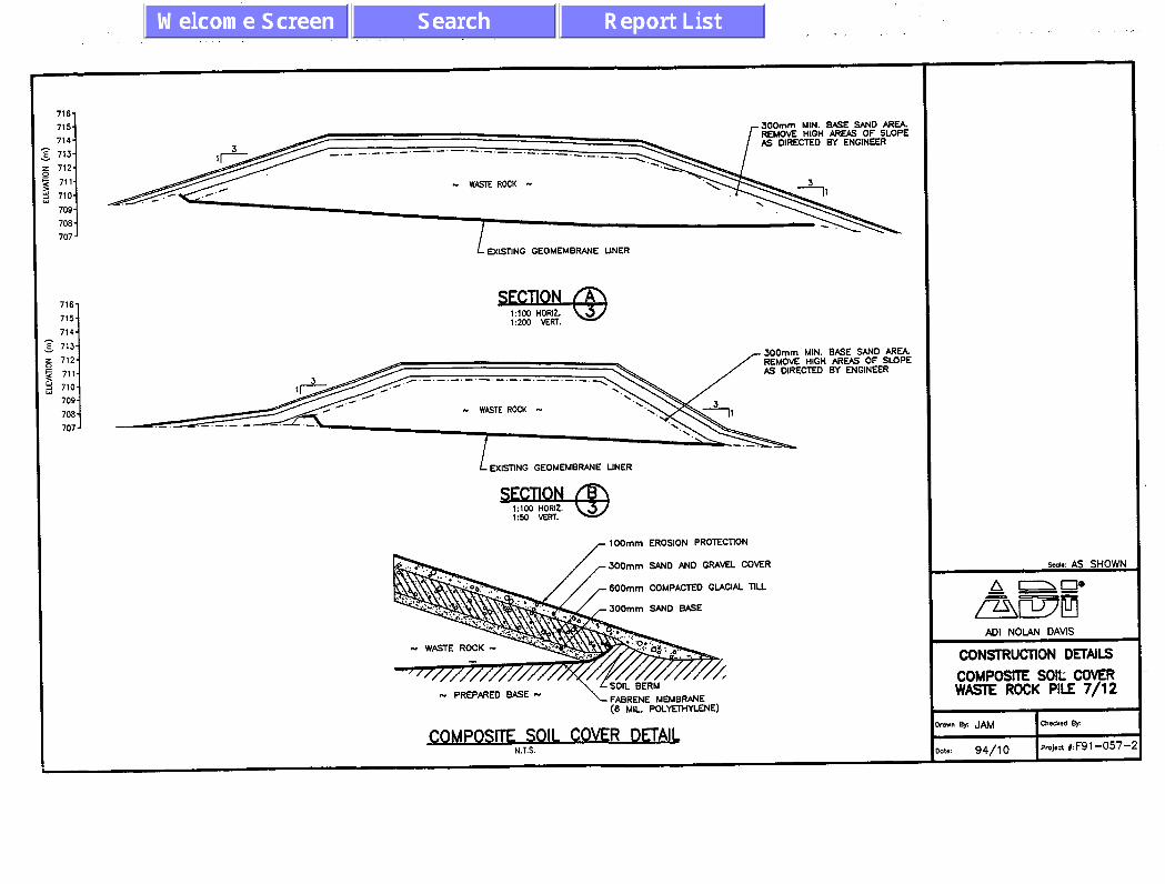
716,
715- 714.
: 713- 712- 711.
i 710- 709 - 708-
707 -
716-
715- 714-
; 713- 5 712-
$ 711- j 710-
709 - 706 - 707 -
300mm MIN. BASE SAND AREA. REMOVE HIGH AREAS OF SLOPE AS DIRECTED BY ENGINEER
. WASTE ROCK -
1 EXSTING CEOMEMBRANE LINER
300mm MIN. EASE SAND AREA. REMOVE HIGH AREAS OF SLOPE AS DIRECTED BY ENGINEER
1 EXlSllNG GEOMEMBRANE LINER
r 100mm EROSION PROTECTlON
,300mm SAND BASE
- PREPARED BASE -
(6 ML. POLYETHYLENE)
.-.
%.a*: AS SHOWN
A IO' = a= /71\wlY
ADI NOLAN DAVE
CONSTRUCTION DmAiLS COMPOSITE SOlt COVER WASTE ROCK PILE 7/12

--
1DOmm D!A DRAlN TIlE TO SEDIHENTATION POND
SITF PI AN - COMH- COVFR LYSIWFR PIACEMENT DFTAll.
EMBED 50mm WA. Put PIPE IN SAND LAYER
SOmm PVC PIPE AT 0.022 SLOPE
1DOmm DK DRUN ?l1E . WASTE ROCK N
EXISTING WASTE ROCK
LIT&L STRUCTURE
SECTION N.T.S.
W’ICAA MOISTURE & PRESSURE PROBE
7
MD(D EXBllNG YONITDRING PROBE caws w REQUIRED. (SEE Mpca
cmwosm SOIL COMR 7 MONITORING PROBE DEML BELOW)
CRUSH MATERIM FOR VOID INFlU
N.T.S.
EhlENDED HONlTORlNG /PROBE CX~NG
coMPosm SOIL cow
TYPICAL MONITORING PRORF DETAk N.T.S.
GFNQ ? EXISTING YONITCftlNG PROBE
cpdo’ IRON BAR CONTROL PCHNT k NUMBER
4%Gs%Gi (IF REQUIRED)
sco~a: AS SHOWN
I\IU
ADI NOIAN DAVE
CONSTRUCTION DEWIS COMPOSKE SOIL COVER WASTE ROCK PILE 7/12
3t.: 94/10 1 ~rojact i: F9 1-057-