engineering project proposal portable lift for
TRANSCRIPT
Engineering Project Proposal Portable Lift for Transferring Wheelchair Patients to Elevated Vehicle
Team 15 Kevin Hsu
Vania Kurikesu Matthew Momon
James Walter Charles Wineland III
Sponsor
Dr. James Leonard UM Department of Physical Medicine and Rehabilitation
Section Instructor Professor Albert Shih
Daniel Johnson
1
Contents EXECUTIVE SUMMARY .................................................................................................................................. 6
ABSTRACT ...................................................................................................................................................... 7
PROBLEM DESCRIPTION ................................................................................................................................ 7
INFORMATION SOURCES .............................................................................................................................. 8
CUSTOMER REQUIREMENTS AND ENGINEERING SPECIFICATIONS .............................................................. 8
Customer Requirements ........................................................................................................................... 8
Engineering Targets .................................................................................................................................. 9
PROBLEM ANALYSIS .................................................................................................................................... 11
Design Concepts ...................................................................................................................................... 12
CONCEPT GENERATION............................................................................................................................... 12
The Interview .......................................................................................................................................... 12
Brainstorming .......................................................................................................................................... 13
Bottle Jack with Scissor Lift Frame ...................................................................................................... 13
Inflatable Air Jack with Scissor Lift Frame ........................................................................................... 13
CONCEPT SELECTION PROCESS ................................................................................................................... 13
Lifting and Support Mechanisms ............................................................................................................ 14
Air Jack with Scissor Support Structure: ............................................................................................. 14
Air Jack with Vertical Poles for Support Structure: ............................................................................. 15
Bottle Jack Powered Scissor Lift: ......................................................................................................... 15
Pulley Based Lift: ................................................................................................................................. 16
Wheelchair Securing Mechanisms .......................................................................................................... 17
Clamps over Wheelchair Wheel .......................................................................................................... 17
Depression in Wheelchair Platform .................................................................................................... 18
Hook and Cable ................................................................................................................................... 18
Chosen Lifting and Support Mechanism ................................................................................................. 20
Chosen Wheelchair Securing Mechanism ............................................................................................... 21
THE ALPHA DESIGN ..................................................................................................................................... 21
Air Jack .................................................................................................................................................... 22
Scissor Lift Mechanism ............................................................................................................................ 23
Wheelchair Securing Mechanisms .......................................................................................................... 23
User Operation ........................................................................................................................................ 23

2
ALPHA DESIGN PROBLEM ANALYSIS ........................................................................................................... 24
Engineering Fundamentals ..................................................................................................................... 24
Potential Problems and Prototype Testing ............................................................................................. 24
ENGINEERING DESIGN PARAMETER ANALYSIS ........................................................................................... 25
Identifying the Problem Areas ................................................................................................................ 25
Ramp Stresses and Forces ................................................................................................................... 28
Stress ................................................................................................................................................... 30
Platform Stresses ................................................................................................................................ 32
Bending along length .......................................................................................................................... 32
Bending along platform width ............................................................................................................ 34
Angle of Stability ................................................................................................................................. 35
Assumptions: ....................................................................................................................................... 36
Calculations: ........................................................................................................................................ 36
Bending Moment in Linkage Connector Slot .......................................................................................... 37
Assumptions: ....................................................................................................................................... 38
Calculations: ........................................................................................................................................ 38
Shear Stress in Ramp Bolt Hole ............................................................................................................... 39
Assumptions ........................................................................................................................................ 40
Calculations ......................................................................................................................................... 40
Material Selection Using CES .................................................................................................................. 40
Mechanical Properties ........................................................................................................................ 40
Weather Related Properties ............................................................................................................... 41
Design for the Environment .................................................................................................................... 43
Failure/Safety Analysis using Failure Mode and Effect Analysis (FMEA) ................................................ 43
FINAL DESIGN .............................................................................................................................................. 44
Base Piece ............................................................................................................................................... 45
Scissor Mechanism .................................................................................................................................. 45
Platform/Ramp ....................................................................................................................................... 46
Securing Mechanisms ............................................................................................................................. 47
Air Jack .................................................................................................................................................... 47
Additional Components .......................................................................................................................... 48
Scissor Lift Connection to Base & Platform: ....................................................................................... 48

3
Air Jack Connection to Base & Platform: ............................................................................................ 48
How to Operate ...................................................................................................................................... 48
Bill of Materials ....................................................................................................................................... 49
MANUFACTURING PLAN ............................................................................................................................. 49
Ramps and Tracks ................................................................................................................................... 49
Scissor Linkages ....................................................................................................................................... 50
Pin Joints ................................................................................................................................................. 50
Slot Joints ................................................................................................................................................ 50
Base and Supports .................................................................................................................................. 50
Air Jack .................................................................................................................................................... 50
Spacers .................................................................................................................................................... 51
Seatbelts.................................................................................................................................................. 51
Handle ..................................................................................................................................................... 51
Casters ..................................................................................................................................................... 51
Assembly ................................................................................................................................................. 51
VALIDATION ................................................................................................................................................ 52
Testing Plans ........................................................................................................................................... 52
Test Results ............................................................................................................................................. 53
ENGINEERING CHANGES NOTICE (ECN) – CHANGES IN DESIGN SINCE DR 3 .............................................. 54
Base ......................................................................................................................................................... 54
Pin Joint ................................................................................................................................................... 56
Slot Joint .................................................................................................................................................. 57
Scissor Links ............................................................................................................................................ 58
Ramp ....................................................................................................................................................... 59
Tracks ...................................................................................................................................................... 60
DISCUSSION ................................................................................................................................................. 61
Strengths ................................................................................................................................................. 61
Lightweight ......................................................................................................................................... 61
Compact .............................................................................................................................................. 61
Inexpensive ......................................................................................................................................... 61
Weaknesses ............................................................................................................................................ 61
Stability ............................................................................................................................................... 61

4
U‐Channel Width:................................................................................................................................ 62
Air Jack Hose ....................................................................................................................................... 62
Handle ................................................................................................................................................. 62
RECOMMENDATIONS ................................................................................................................................. 62
Stability ................................................................................................................................................... 62
Flatten Base Piece ............................................................................................................................... 62
Increase Rigidity of Base Piece ............................................................................................................ 62
Increase Rigidity of Platform Connector Pieces .................................................................................. 63
U‐Channel Width ................................................................................................................................. 63
Handle ................................................................................................................................................. 63
Thinner linkages and U‐channels ........................................................................................................ 63
CONCLUSIONS ............................................................................................................................................. 64
ACKNOWLEDGEMENTS ............................................................................................................................... 65
REFERENCES ................................................................................................................................................ 65
APPENDIX A.1 ‐ Design Concept #1: Scissor Lift .......................................................................................... 66
APPENDIX A.2 ‐ Design Concept #2: Pulley Lift .......................................................................................... 67
APPENDIX A.3 ‐ Design Concept #3: Bottle Jack Lift .................................................................................. 68
APPENDIX A.4 ‐ Design Concept #4: Easylift Airjack ................................................................................. 69
APPENDIX A.5 ‐ Design Concept #5: Wheelchair Securing Mechanism ..................................................... 70
APPENDIX B ‐ QFD ....................................................................................................................................... 71
APPENDIX C ‐ Gantt Chart ........................................................................................................................... 72
APPENDIX D ‐ Biographies ........................................................................................................................... 73
APPENDIX E.1 ‐ AmeriGlide 325‐FP Hitch Wheelchair Lift [1] ..................................................................... 76
APPENDIX E.2 ‐ Braun Millennium Series Wheelchair Lift [2] ..................................................................... 77
APPENDIX F.1 ‐ Ramp Stresses and Forces Calculation: ............................................................................. 78
APPENDIX F.2 ‐ Calculations for upper thickness of connector slot for scissor linkages: ........................... 79
APPENDIX F.3 ‐ Calculations for shear stress in ramp bolt hole: ................................................................ 80
APPENDIX G.1 ‐ Prototype Parts ................................................................................................................. 81
APPENDIX G.2 – Prototype Dimensions (Dimensions in cm.) ..................................................................... 82
APPENDIX H – Old Base (Dimensions in cm.) .............................................................................................. 83
APPENDIX I – Scissor Linkage (Dimensions in cm.) ..................................................................................... 84
APPENDIX J – Platform Track (Dimensions in cm.) ..................................................................................... 85

5
APPENDIX K – Ramp Component (Dimensions in cm.) ............................................................................... 86
APPENDIX L ‐ Platform Connecting Supports (Dimensions in cm.) ............................................................. 87
APPENDIX M ‐ Air Jack Components ........................................................................................................... 88
APPENDIX N ‐ Pin Component (Dimensions in cm.).................................................................................... 89
APPENDIX O ‐ Slot Component (Dimensions in cm.) .................................................................................. 90
APPENDIX P.1 ‐ Tip Angle Matlab File ......................................................................................................... 91
APPENDIX P. 2 ‐ Ramp Stresses Matlab File ................................................................................................ 93
APPENDIX P.3 ‐ Platform Stress (Shortway) Matlab File ............................................................................. 95
APPENDIX P.4 ‐ Platform Stress (Longway) Matlab File .............................................................................. 96
APPENDIX P.5 ‐ Scissor Linkage Lateral Stress ............................................................................................ 98
APPENDIX Q ‐ Bill of Materials: ................................................................................................................... 99
APPENDIX R.1 ‐ SimaPro Design for Environment – Mass Breakdown ..................................................... 100
APPENDIX R.2 ‐ SimaPro Design for Environment – Characterization ...................................................... 101
APPENDIX R.3 ‐ SimaPro Design for Environment – Normalization.......................................................... 102
APPENDIX R.4 ‐ SimaPro Design for Environment – Single Score ............................................................. 103
APPENDIX S.1 ‐ Failure Mode Engineering Analysis .................................................................................. 104
6
EXECUTIVE SUMMARY We have been asked by Dr. James Leonard from the University of Michigan Orthotics and Prosthetics Center to design and build a portable wheelchair lift. Moving wheelchair bound people from their chair into a vehicle is often time consuming. The process gets more complex when the patient has to be lifted out of the chair and into a truck with an elevated seat height. Current technologies, such as modified vehicles, are often very expensive or very heavy. Additional devices such as ramps are installed into the vehicle, making them usable exclusively for the vehicle modified. A portable, inexpensive wheelchair lift would greatly increase accessibility for wheelchair-bound patients and increase their options for transportation. Our objective is to create a wheelchair lift that is both portable and inexpensive. The lift should be compatible with standard manual wheelchairs and require no modifications to the wheelchair or the vehicle. The lift should be capable of lifting at least a 250 lb (141kg) person and their wheelchair to a height 2 inches (5.08 cm) above the height of a standard SUV seat. Our final design is an air jack powered by car exhaust, or by an external air compressor. The jack is supported by a scissor lift frame which holds the jack in place and allows for uniform lifting of the tracks to correct seat height. The entire frame is made of aluminum, which is strong, lightweight, anti-corrosive and easy to machine. The device is designed so that the air jack carries a majority of the load, and the frame ensures the jack’s stability. Additionally, the tracks have locking mechanisms to further hold the wheelchair in place. Our prototype contains a few modifications from our original design. Since we were not able to get stock material pre-machined to our specifications, a majority of our machining time consisted of cutting away material to lower the overall weight. We used primarily the band saw and mill to cut our stock to length and to machine away excess material. We increased the base footprint by 2 sq in. to better accommodate the air-jack, which didn’t affect portability. We also changed the bolt size of all bolts used due to resource restraints. This also did not affect our target values. After testing our prototype, we discovered some major issues with the stability of our device. We discovered that welding our components together caused problems when the aluminum contracted after cooling. This caused parts to bend considerably and lowered our stability below our acceptable values. We believe that weight can be removed from other components such as the U-channels, and moved to increase the rigidity of the base, which would increase stability. We learned that our ramps and tracks are barely capable of fitting a standard wheelchair, which makes it very difficult to roll a wheelchair up the ramp. We discovered that the hose for the air jack was very prone to kinking and increasing the time to inflate. Despite these flaws, the lift was more than capable of lifting 300 lbs, weighed only 45.5 lbs, and could fit comfortably in the trunk of a subcompact car. We concluded that our prototype proves that using an air-jack as a wheelchair lift is a viable concept that should be researched further.

7
ABSTRACT Transporting a patient from a wheelchair into a vehicle can be a time consuming and difficult process. The problem is magnified when the patient is moved into a vehicle with an elevated seat height, such as an SUV. While some technologies exist to help with this problem, they are often expensive and too heavy to be moved to different locations. A portable wheelchair lift would greatly increase accessibility for wheelchair-bound patients and increase their options for transportation. Our team will be working with Dr. James Leonard from the University of Michigan Department of Physical Medicine and Rehabilitation to design a portable wheelchair lift to assist people in transferring from their wheelchair into a high vehicle seat, such as in a SUV or pickup truck. PROBLEM DESCRIPTION We spoke with Dr. James Leonard, the sponsor of this project at the University of Michigan Orthotics and Prosthetics Center. We learned the inspiration for this project came from one of his patients. This patient has little trouble moving herself into her own car using a sliding board shown below in Figure 1. However, she has difficulties when traveling with friends who own SUVs, due to the large difference in seat height between the vehicle and the wheelchair. This patient has a powered chair that can elevate her to the correct seat height, but the device is heavy and can't be transported with her. This introduced the need for a lift device that could not only lift a wheelchair bound patient high enough to assist them into a vehicle, but also small and light enough that it can be carried with them.
Figure 1: Sliding Board
8
INFORMATION SOURCES We’ve searched both patents and commercial products to gain an understanding of what is currently available. Although there are many patents, like US 4,138,023, describing wheelchair lifts, none were uncovered that fit the aim of our project. The same held true for products on the market. Because of this, we focused in on “best-designs” for two different approaches. The first product is the AmeriGlide 325-FP, a trailer hitch mounted lift [1]. The AmeriGlide, found in Appendix E.1, costs $1,300. It has a lift capacity of over 250 lbs. The AmeriGlide is also completely separate from the vehicle and does not require any modifications to be done. However, the AmeriGlide does not really aid in lifting a person in a wheelchair into a vehicle. Instead it is used to transport just the wheelchair by attaching it to the towing hitch of a vehicle. This also means that the AmeriGlide could not be transported in the trunk of a vehicle and could not be used on a vehicle without a trailer hitch. There is also potential for damaging the vehicle while using the AmeriGlide. The second lift we benchmarked is the Braun Millennium Series, a vehicle mounted lift seen in Appendix E.2 [2]. The Millennium Series, with the vehicle to install it in, can cost over $60,000. The Millennium Series is therefore far more expensive than what we hope to create. The Millennium Series appears to be fairly straight forward and easy to use. It can easily accommodate over 250 lbs without requiring much work from the operator. The Millennium series is also very secure and immune to tipping over. Overall the Millennium Series effectively accomplishes its task of lifting a patient into a van, but it is much too expensive for the scope of our project. We also went to the University of Michigan hospital to observe the various methods that people used for moving themselves into vehicles. One common method for people who had some use of their legs was to use a stool as an intermediate step between the wheelchair and the vehicle. Another device that was used was a lift that utilized a harness system to pick a person up out of a wheelchair and swing them into a vehicle. This did an effective job, but it was very bulky and required lengthy preparation to secure the individual in the lifting harness. CUSTOMER REQUIREMENTS AND ENGINEERING SPECIFICATIONS Customer Requirements After meeting with our project sponsor, Dr. James Leonard, our team began to define the customer requirements for a wheelchair lift and rank them according to relative importance. Safety is the highest priority of the customer; therefore, the two highest ranked customer requirements are that the wheelchair lift secures the wheelchair in place and does not tip over during operation. The next biggest concern to wheelchair lift customers is portability. The device must be easy to lift and then fit into the trunk of the customer’s vehicle. These two
9
requirements were both given a weight of 9 in the QFD, shown in Appendix B. Another requirement of the lift is that it must raise the wheelchair seat height 2 inches above the vehicle seat height. This allows for a smoother transfer for the patient from the lift into the vehicle seat as it takes less work for one to lower themselves into a seat than lift their own body weight into a higher seat. Because many of the customers have other physical ailments in addition to their disability that can lead to weight gain or obesity, this is of special importance [4]. Therefore, this customer requirement is given a weight of 8. We rated this lower than our portability requirements because a non-portable lift would be no different from what is already available on the market and render our lift useless. An additional customer requirement comes in to play with the daily use of the wheelchair lift. With the powered lift operating so close to the side of the vehicle and then being stored in the trunk, customers want a design that will not damage the vehicle in any way. This requirement also ranks at a weight of 8 on the QFD because it is important that the vehicle does not get scratched during the use of the wheelchair lift. The next major customer requirement was that the lift should be reasonably priced. This was weighted a 7, to ensure that the product is readily accessible to those who would need it, customers who very often have limited income. Additionally, to cater to an optimal amount of customers, the wheelchair lift should be weight-rated to support up to a 250 lb person. Ease of operation is another key customer requirement rated at 5. Our lift design should not be overly complicated and should not require any advanced technical knowledge to operate. It is important that both the patient and the operator find the lift both convenient and efficient. Next, the wheelchair lift should withstand all weather conditions. This was ranked with a weight of 4 on the QFD. The capabilities of the lift should not be compromised due to outdoor temperatures or even rain and snow. Finally, the lift should accommodate all manual wheelchair sizes. Compared to safety and portability these last few requirements are not as significant but they are definitely criteria that have considerable importance to the customer. Engineering Targets Once our team finalized our customer requirements we translated them into engineering targets to set quantifiable standards for our design. These engineering targets are listed below in Table 1.
10
Table 1: Engineering Target Values
Engineering Targets Target Values Maximum Lift Capacity 141 kg Maximum Lowering Speed 5 cm/s Weight 23 kg Prototype Cost $1,375.00 Maximum Angle before Tipping Over 7 degrees Footprint Area 63.5 cm x 76.2 cm Compacted Dimensions 79 x 100 x 122 cm Distance between Wheelchair Wheels 48 – 61 cm Maximum Force Required from Operator 445 N Maximum Extension Height 59 cm Time Required to Extend to Maximum Height 1 minute
In order to determine the engineering targets, we brainstormed measurable quantities that directly correlate to the customer requirements. The final prototype cost is one way to measure whether or not the customer requirement of having a reasonably priced wheelchair lift will be met. The prototype cost target is set at $1,375, which is the cost of the AmeriGlide 325-FP, a wheelchair lift whose capabilities match our design requirements [1]. To measure portability in our lift design we decided to measure the weight and the compacted dimensions. These two engineering targets correlate to whether or not the prototype is easy to lift and easy to fit into the vehicle trunk. The maximum weight is set at 23 kg (50 lbs) because according to OSHA standards, lifting weights of more than this amount increases the risk of injury [5]. The compacted dimension target value is 79 x 100 x 122 cm. These are the actual dimensions of the trunk space of the Buick Enclave, a vehicle that stands as an average of the types of vehicles our lift will cater to. In order to create a design that is able to withstand all weather conditions, we will need to measure the footprint area of our prototype. This target value is set at 63.5 cm x 76.2 cm which was the platform area of a wheelchair scale measured at the University of Michigan Orthotics and Prosthetics Center. To quantify the ease of operation of our device, we chose to measure the maximum force required from the user, the maximum lowering speed and the weight of the wheelchair lift. We set the target value of the applied force from the user at 445 N (100 lbs) so that a light-weight person could potentially operate our device by stepping on a foot lever, using their body weight alone. After researching a current hydraulic wheelchair lift on the market, the Millennium Series, we decided to set the target value of the lowering speed to 5 cm/s [2]. Another customer requirement of the wheelchair lift is that it must rise 5 cm above the seat height of the vehicle. In order to evaluate this we decided to measure the maximum extension

11
height of the lift and set this target value to 59 cm. We calculated this value by taking the difference in the average wheelchair seat height (45-51 cm) and the seat height of the 2009 GMC Yukon (100 cm), a representative full-sized SUV, and then added the additional 5 cm for ease in transport of the patient. The next customer requirement is to have a lift that accommodates all manual wheelchairs, and we chose to use the corresponding engineering targets of the footprint area and the distance between the wheelchair wheels to judge this. We have to account for the variability in manual wheelchair sizes here and make sure we have enough space on our lift to efficiently operate. The target value of the distance between wheelchair wheels is between 48 and 61 cm. These values were determined after measuring both a small adult wheelchair and a large adult wheelchair to find a good range of distances [3]. In addition, to determine whether or not the lift is weight-rated to support a 250 lb person, we can measure the maximum lift capacity, the time required to fully extend the lift and the maximum force required by the operator. Our maximum lift capacity target is set at 141 kg (310 lbs) which is the sum of our average patient weight (250 lbs) and the maximum weight of a manual wheelchair (60 lbs) specified by our project sponsor [4]. We recorded the amount of time it took for a powered built-in lift to raise a load into a van as 25 seconds and then multiplied by a factor of 2.5 in order to compensate for a mechanical and portable design [3]. To make sure our wheelchair lift does not damage the vehicle when in use or in storage, we will use a combination of the footprint area, compacted dimensions and distance between the wheelchair wheels to avoid a bulky design with sharp corners that is prone to bump or scratch the vehicle. To evaluate the safety of our lift and to be confident that it will secure the wheelchair in place and remain upright, we quantified the engineering targets as the distance between wheelchair wheels, the footprint area and the maximum angle before tipping over. The maximum angle target value is 7 degrees from the horizontal. The largest amount of tilt experienced by the wheelchair lift would be on a steep driveway. The National Highway Institute recommends less than an 8% slope angle for local driveways [6]. Using a safety factor of 1.5 we calculated to the angle of a 12% slope to be about 7 degrees. PROBLEM ANALYSIS The major design drivers for our wheelchair lift are portability and safety. These are the two most important consumer requirements. Being highly portable is what will separate our design from the plethora of lifting devices that are currently out on the market, while safety is an absolute must for any sort of medical device. The major difficulty of the design will be to come up with something that is both lightweight and very strong. Other difficulties will be how to supply enough force to lift a person with only a small amount of volume within which to put any mechanical or electric devices, and how to achieve all of the design criteria without resorting to overly expensive materials and processes.
12
Design Concepts Our first design concept, shown in Appendix A.1, is a scissor lift. It would utilize a hydraulic cylinder to actuate a scissor mechanism to push up the lift. The second design concept, shown in Appendix A.2, utilizes a pulley lift to pull up the platform with the wheelchair, much as an elevator operates. The pulley system could operate with an electric motor powered either by a battery or through the car’s cigarette lighter outlet, or with a hand crank. The third design, shown in Appendix A.3, concept uses a bottle jack to vertically lift the wheelchair platform. The bottle jack can be actuated through the use of a lever or crank. The fourth design, shown in Appendix A.4, concept uses an air jack to lift up the platform with the wheelchair. The air jack can either be powered directly by the car’s hot exhaust, or with an external air compressor. The fifth design concept, shown in Appendix A.5, is a device to help secure the wheelchair. A portion of the track would be connected to a high tension spring. When the wheelchair is on the platform, the spring would compress, and secure the wheelchair in a depression. CONCEPT GENERATION When we first began this project, we were given a very abstract idea of our objective. Due to time conflicts, we were not able to meet with our sponsor, Dr. James Leonard, as early as we had hoped. In the meantime, we observed wheelchair-bound patients getting in and out of vehicles at the University of Michigan Hospital. Afterwards, we individually brainstormed ideas. We reconvened and discussed the ideas, but not much could be obtained from this session until we understood the scope of the project. Once we met with Dr. Leonard, many of our questions were answered regarding our true objective, and the scope of the project was considerably narrowed. Once we knew how we wanted to proceed, most of our original ideas were scrapped. We researched available technology to create a benchmark. We held one more brainstorming session to come up with ideas that used our newfound data. From the most feasible ideas, we created a selection matrix to highlight advantages and disadvantages in each idea. From this, we created our Alpha Design. The Interview We met with Dr. Leonard at his office in the University of Michigan Center for Orthotics and Prosthetics. Dr. Leonard gave us a more detailed outline of the objective and helped us better understand his expectations. We learned that his patients have little to no trouble getting in and out of a car. The patients use a sliding board that they wedge between themselves and the seat. Patients have little trouble with this method because the difference between average wheelchair seat height and average sedan seat height is very small. The problem occurs when a patient tries to get into a vehicle with an elevated seat height, such as a truck or SUV. The difference in seat height is much greater and a lift must be used to get to a height where the sliding board can be used. The lifts are very heavy and usually must remain in a fixed spot. Dr. Leonard asked us to create a lift that could be transported with a wheelchair. Once the patient is at the correct height,

13
they can handle getting in and out of the vehicle themselves. This significantly reduced the scope of our project, since our only objective now was to lift the wheelchair, instead of lifting a patient out of the chair and into the vehicle. Brainstorming After meeting with Dr. Leonard, we held another brainstorming session to use our new information. Since portability was the primary factor for the designs, we decided to create a lift that would be manually operated, since an electric motor would add considerable weight to any design we chose. The new ideas included a scissor lift device which was a more compact version of a lift currently used to transport wheelchair patients, a forklift type device with a hand-cranked worm gear, a platform with a compact hydraulic bottle jack with hand pump underneath, and an inflatable air jack placed under the wheelchair which could run on an air compressor or the exhaust from a car. From these designs we deliberated and came down to two potential alpha designs. Bottle Jack with Scissor Lift Frame We combined the bottle jack and scissor lift to take advantage of the load capacity of the bottle jack, combined with the compactness of the scissor lift. The bottle jack is placed in a horizontal position next to the sliding end of a scissor lift. The other end is fixed in place. The hand pump is in a vertical position and applies force to the rolling end of the scissor lift, moving the platform up. Inflatable Air Jack with Scissor Lift Frame The second potential alpha design combined an inflatable air jack with a scissor lift frame. The air jack is very lightweight yet still has a large load capacity. The main concern would be stability; in order to address this, we combined the scissor lift frame with the air jack. A scissor lift built around the air jack would serve to keep the air jack from inflating unevenly, and would provide lateral support. CONCEPT SELECTION PROCESS After we had created our design concepts it was time to narrow down the list of candidates and to more thoroughly investigate the positive and negative aspects of each. In the end we took a closer look at four different lifting and support mechanisms for the wheelchair lift, as well as three different mechanisms for securing the wheelchair in place. We listed the positive and negative aspects for each concept (see Table 2) and used this to determine which concept should be our alpha design.
14
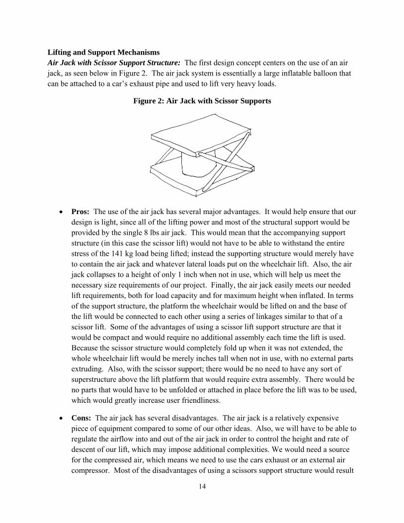
Lifting and Support Mechanisms Air Jack with Scissor Support Structure: The first design concept centers on the use of an air jack, as seen below in Figure 2. The air jack system is essentially a large inflatable balloon that can be attached to a car’s exhaust pipe and used to lift very heavy loads.
Figure 2: Air Jack with Scissor Supports
• Pros: The use of the air jack has several major advantages. It would help ensure that our design is light, since all of the lifting power and most of the structural support would be provided by the single 8 lbs air jack. This would mean that the accompanying support structure (in this case the scissor lift) would not have to be able to withstand the entire stress of the 141 kg load being lifted; instead the supporting structure would merely have to contain the air jack and whatever lateral loads put on the wheelchair lift. Also, the air jack collapses to a height of only 1 inch when not in use, which will help us meet the necessary size requirements of our project. Finally, the air jack easily meets our needed lift requirements, both for load capacity and for maximum height when inflated. In terms of the support structure, the platform the wheelchair would be lifted on and the base of the lift would be connected to each other using a series of linkages similar to that of a scissor lift. Some of the advantages of using a scissor lift support structure are that it would be compact and would require no additional assembly each time the lift is used. Because the scissor structure would completely fold up when it was not extended, the whole wheelchair lift would be merely inches tall when not in use, with no external parts extruding. Also, with the scissor support; there would be no need to have any sort of superstructure above the lift platform that would require extra assembly. There would be no parts that would have to be unfolded or attached in place before the lift was to be used, which would greatly increase user friendliness.
• Cons: The air jack has several disadvantages. The air jack is a relatively expensive piece of equipment compared to some of our other ideas. Also, we will have to be able to regulate the airflow into and out of the air jack in order to control the height and rate of descent of our lift, which may impose additional complexities. We would need a source for the compressed air, which means we need to use the cars exhaust or an external air compressor. Most of the disadvantages of using a scissors support structure would result

15
from the complexity of building the lift: all of the linkages and pins would require a fair bit of precise fabrication and assembly.
Air Jack with Vertical Poles for Support Structure: The second design concept (see Figure 3 below) also centers on using an air jack as the lifting mechanism but uses vertical poles to guide the wheelchair platform as it moves vertically. This system has all of the advantages and disadvantages of using an air jack mentioned in the previous section. The key difference in this design from the previous design is the supporting structure used to keep the platform stable. This design uses vertical poles as rails that the platform moves up and down on.
Figure 3: Air Jack with Vertical Poles
• Pros: The main advantages are simplicity and a slight weight advantage over the scissor lift concept.
• Cons: It would be rather difficult to design the poles so that they can both be a guide for the vertical travel of the platform, but also be collapsible so that we can meet our size requirements. The structure would likely require some sort of assembly before and after each use in order to compensate for this, which would severely hurt our user friendliness. Also, there would likely be stability and tilting problems with the poles under lateral loads.
Bottle Jack Powered Scissor Lift: The third design concept (see Figure 4 below) uses a simple bottle jack to power a scissors lift to raise the wheelchair platform. In this case, the bottle jack would replace the hydraulic lifting mechanisms found in most scissor lifts.
Air Jack
Air inlet

16
Figure 4: Bottle Jack Powered Scissor Lift – Front View
• Pros: There are many advantages to this approach. The scissor lift is a proven technology, as is the bottle jack. The scissor lift provides a great deal of stability if designed correctly. The bottle jack itself is a rather light mechanism; a 1.5 ton jacks weigh under 8 lbs. The bottle jack can be manually powered, which frees us from any constraints related to harnessing the energy from the car’s electrical system or exhaust. Also, the Bottle Jack is rather inexpensive. Finally, the scissor lift would collapse down to a rather small volume, making our lift much more portable.
• Cons: The major disadvantages of this design mostly come down to one issue: weight. Because the scissor lift structure would have to support the entire load being lifted, all of the components of the scissor lift would have to be very robust, which would add to the lift’s weight. This can be seen from the benchmarked AmeriGlide 325-FP Hitch Wheelchair Lift in Appendix E.1 which has performance specifications similar to what we are aiming for but weighs over 200 lbs. Thus, despite all of the advantages using a scissor lift as our lifting mechanism, the issue of weight might be insurmountable.
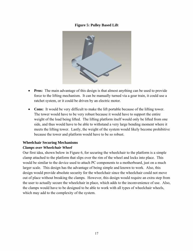
Pulley Based Lift: Our last design for the lifting and support mechanism is a pulley based system as seen below in Figure 5. This system would operate by having a tower structure that the platform would be attached to. The platform would be pulled up the tower by a chain or wire attached to a pulley at the top of the tower. This chain or wire could then be drawn or let out with some sort of driving mechanism, which could be almost anything.
Bottle Jack
Input lever
17
Figure 5: Pulley Based Lift
• Pros: The main advantage of this design is that almost anything can be used to provide force to the lifting mechanism. It can be manually turned via a gear train, it could use a ratchet system, or it could be driven by an electric motor.
• Cons: It would be very difficult to make the lift portable because of the lifting tower. The tower would have to be very robust because it would have to support the entire weight of the load being lifted. The lifting platform itself would only be lifted from one side, and thus would have to be able to withstand a very large bending moment where it meets the lifting tower. Lastly, the weight of the system would likely become prohibitive because the tower and platform would have to be so robust.
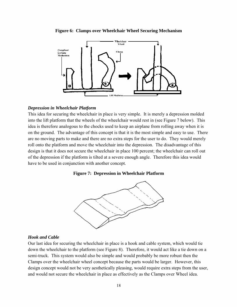
Wheelchair Securing Mechanisms Clamps over Wheelchair Wheel Our first idea, shown below in Figure 6, for securing the wheelchair to the platform is a simple clamp attached to the platform that slips over the rim of the wheel and locks into place. This would be similar to the device used to attach PC components to a motherboard, just on a much larger scale. This design has the advantage of being simple and known to work. Also, this design would provide absolute security for the wheelchair since the wheelchair could not move out of place without breaking the clamps. However, this design would require an extra step from the user to actually secure the wheelchair in place, which adds to the inconvenience of use. Also, the clamps would have to be designed to be able to work with all types of wheelchair wheels, which may add to the complexity of the system.
18
Figure 6: Clamps over Wheelchair Wheel Securing Mechanism
Depression in Wheelchair Platform This idea for securing the wheelchair in place is very simple. It is merely a depression molded into the lift platform that the wheels of the wheelchair would rest in (see Figure 7 below). This idea is therefore analogous to the chocks used to keep an airplane from rolling away when it is on the ground. The advantage of this concept is that it is the most simple and easy to use. There are no moving parts to make and there are no extra steps for the user to do. They would merely roll onto the platform and move the wheelchair into the depression. The disadvantage of this design is that it does not secure the wheelchair in place 100 percent; the wheelchair can roll out of the depression if the platform is tilted at a severe enough angle. Therefore this idea would have to be used in conjunction with another concept.
Figure 7: Depression in Wheelchair Platform
Hook and Cable Our last idea for securing the wheelchair in place is a hook and cable system, which would tie down the wheelchair to the platform (see Figure 8). Therefore, it would act like a tie down on a semi-truck. This system would also be simple and would probably be more robust then the Clamps over the wheelchair wheel concept because the parts would be larger. However, this design concept would not be very aesthetically pleasing, would require extra steps from the user, and would not secure the wheelchair in place as effectively as the Clamps over Wheel idea.

19
Figure 8: Hook and Cable Securing Mechanism
Table 2: Advantages and Disadvantages of Final Design Concepts
Concept (Lifting Mechanisms)
Advantages Disadvantages
Air Jack w/ Scissor supports
• Light weight • Compact • Easy to operate • Easy to make portable • Requires no energy from user
• Air Jack relatively expensive • Hard to control height and
rate of descent • Lots of parts to fabricate
Air Jack w/ vertical pole supports
• Light weight • Few parts – Simple to make • Requires no energy from user
• Air Jack relatively expensive • Difficult to make portable do
to vertical supports • Difficult to make vertical
supports stable
Bottle Jack powered scissor lift
• Proven technology • Relatively inexpensive • Can make compact
• Very difficult to make light enough
• Difficult to place bottle jack
Pulley lift • Can be powered by any number of mechanisms and power sources
• Very difficult to make portable
• Lots of moving parts • Likely very heavy
Concepts (Securing Mechanisms)
Advantages Disadvantages
Clamps over Wheels
• Proven technology in other fields
• Makes wheelchair very secure
• Requires extra step from user • Harder to accommodate
different types of chairs
20
Depression in Platform
• Very simple – no moving parts
• No extra work required from user
• Doesn’t secure the wheelchair as well as other designs
Hook and Cable • Easy to accommodate different wheelchairs
• Doesn’t secure as well as Hooks over wheel
• Not aesthetically pleasing • Requires extra step from user
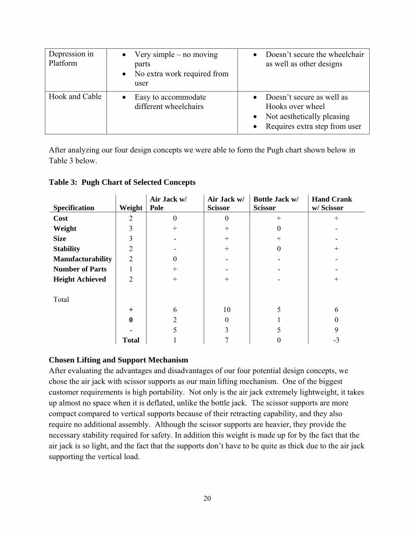
After analyzing our four design concepts we were able to form the Pugh chart shown below in Table 3 below. Table 3: Pugh Chart of Selected Concepts
Specification Weight Air Jack w/ Pole
Air Jack w/ Scissor
Bottle Jack w/ Scissor
Hand Crank w/ Scissor
Cost 2 0 0 + + Weight 3 + + 0 - Size 3 - + + - Stability 2 - + 0 + Manufacturability 2 0 - - - Number of Parts 1 + - - - Height Achieved 2 + + - + Total + 6 10 5 6 0 2 0 1 0 - 5 3 5 9 Total 1 7 0 -3
Chosen Lifting and Support Mechanism After evaluating the advantages and disadvantages of our four potential design concepts, we chose the air jack with scissor supports as our main lifting mechanism. One of the biggest customer requirements is high portability. Not only is the air jack extremely lightweight, it takes up almost no space when it is deflated, unlike the bottle jack. The scissor supports are more compact compared to vertical supports because of their retracting capability, and they also require no additional assembly. Although the scissor supports are heavier, they provide the necessary stability required for safety. In addition this weight is made up for by the fact that the air jack is so light, and the fact that the supports don’t have to be quite as thick due to the air jack supporting the vertical load.
21
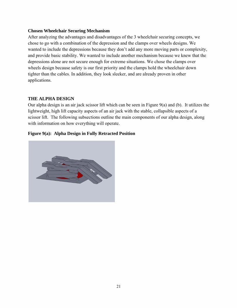
Chosen Wheelchair Securing Mechanism After analyzing the advantages and disadvantages of the 3 wheelchair securing concepts, we chose to go with a combination of the depression and the clamps over wheels designs. We wanted to include the depressions because they don’t add any more moving parts or complexity, and provide basic stability. We wanted to include another mechanism because we knew that the depressions alone are not secure enough for extreme situations. We chose the clamps over wheels design because safety is our first priority and the clamps hold the wheelchair down tighter than the cables. In addition, they look sleeker, and are already proven in other applications. THE ALPHA DESIGN Our alpha design is an air jack scissor lift which can be seen in Figure 9(a) and (b). It utilizes the lightweight, high lift capacity aspects of an air jack with the stable, collapsible aspects of a scissor lift. The following subsections outline the main components of our alpha design, along with information on how everything will operate.
Figure 9(a): Alpha Design in Fully Retracted Position
22
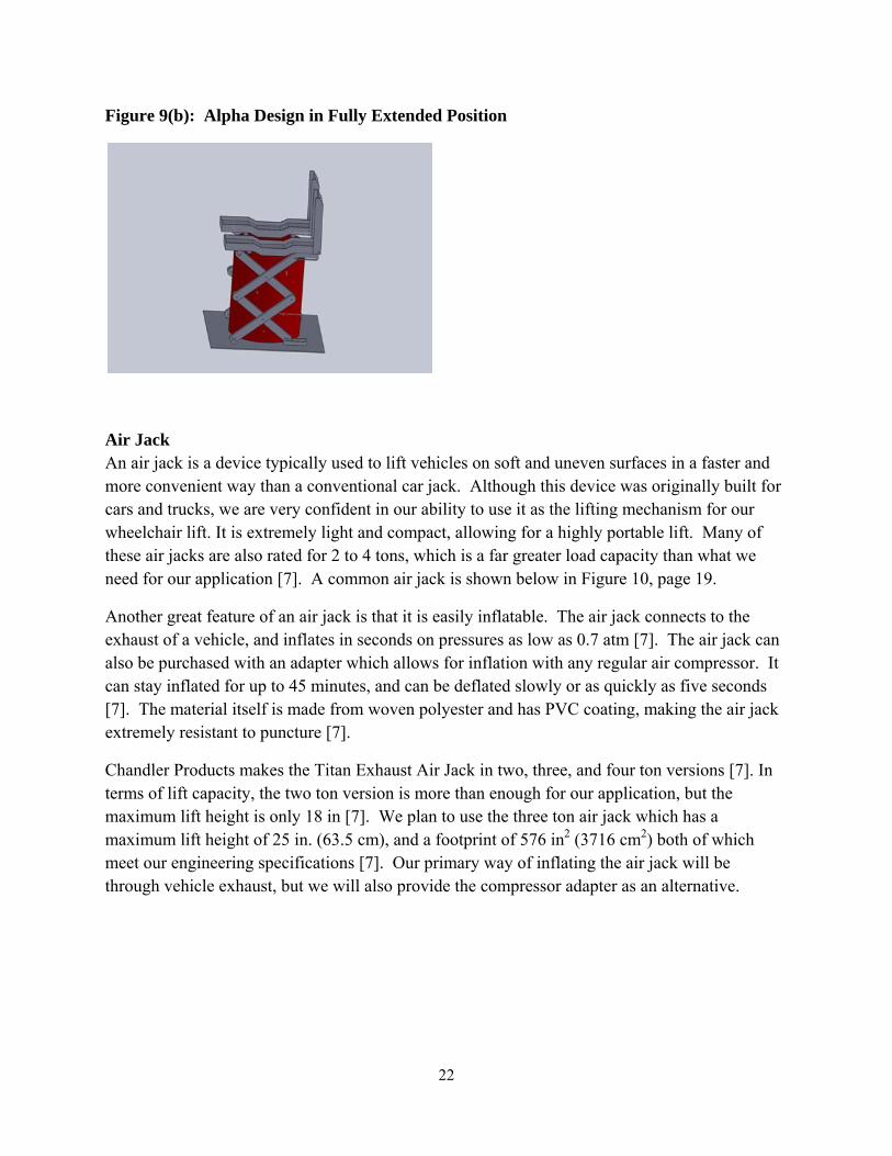
Figure 9(b): Alpha Design in Fully Extended Position
Air Jack An air jack is a device typically used to lift vehicles on soft and uneven surfaces in a faster and more convenient way than a conventional car jack. Although this device was originally built for cars and trucks, we are very confident in our ability to use it as the lifting mechanism for our wheelchair lift. It is extremely light and compact, allowing for a highly portable lift. Many of these air jacks are also rated for 2 to 4 tons, which is a far greater load capacity than what we need for our application [7]. A common air jack is shown below in Figure 10, page 19.
Another great feature of an air jack is that it is easily inflatable. The air jack connects to the exhaust of a vehicle, and inflates in seconds on pressures as low as 0.7 atm [7]. The air jack can also be purchased with an adapter which allows for inflation with any regular air compressor. It can stay inflated for up to 45 minutes, and can be deflated slowly or as quickly as five seconds [7]. The material itself is made from woven polyester and has PVC coating, making the air jack extremely resistant to puncture [7].
Chandler Products makes the Titan Exhaust Air Jack in two, three, and four ton versions [7]. In terms of lift capacity, the two ton version is more than enough for our application, but the maximum lift height is only 18 in [7]. We plan to use the three ton air jack which has a maximum lift height of 25 in. (63.5 cm), and a footprint of 576 in2 (3716 cm2) both of which meet our engineering specifications [7]. Our primary way of inflating the air jack will be through vehicle exhaust, but we will also provide the compressor adapter as an alternative.

23
Figure 10: Two Ton Titan Air Jack [7]
Scissor Lift Mechanism A scissor lift mechanism combines the horizontal motion of the legs with the vertical motion of the platform. One of the biggest advantages of this system is it is very stable. The scissor mechanism keeps the platform completely parallel to the ground at all times, and provides both vertical and lateral support. In our situation, the air jack will be providing all the lift force and will thus be handling the vertical load, but we will rely on the scissor mechanism to keep the platform stable and provide lateral support as well.
Another big advantage of the scissor lift is it collapses into a small compacted height. If we were to use poles or rods to keep the platform stable during operation, it would either decrease the portability of our lift, or increase the complexity by having a system to fold down the poles. With the scissor lift, everything is contained and when the lift is completely lowered, our compacted height will be very low. We will have two ends of the scissor lift secured to the top and bottom platforms, while the other ends slide on tracks as the platform is lifted and lowered.
Wheelchair Securing Mechanisms Our wheelchair lift will incorporate two ways to help secure the wheelchair in place during operation. The first is having two depressions in the platform for the rear and front wheels to sit in, previously shown in Figure 7. When the wheelchair patient rolls onto the platform, the wheels will sit in their respective depressions preventing forward or backward rolling during operation.
Since safety is our first priority, we felt that in addition to the depressions we needed another safety mechanism to further secure the wheelchair to the lift. Our second method is a clamp mechanism previously shown in Figure 6. When the wheelchair is in place, the clamps will come over each of the rear wheels and secure to the platform. They will remain secure throughout operation, and then release when the wheelchair is to be removed. This further prevents the wheelchair from rolling or tipping while on the lift.
User Operation The lift will have an operator that is not the wheelchair patient. The lift will be put in place where the wheelchair patient will wheel onto the platform. The wheels will be sitting in the depressions when the operator will put the clamps over both wheels. The operator will then
24
connect the air jack hose to either the vehicle exhaust or an air compressor to begin the lifting action. When the platform is at the appropriate height, the operator will cut off air flow and proceed to help the patient from the wheelchair to the car seat with the sliding board. From there, the operator will lower the lift into its compact dimensions, undo the clamps, and remove the wheelchair. Then after removing the air hose from either the exhaust or compressor, the air hose can be picked up and placed into the vehicle trunk.
ALPHA DESIGN PROBLEM ANALYSIS Engineering Fundamentals The scientific fields that most relate to our wheelchair lift project include solid mechanics and dynamics. The purpose of our lift is to raise a wheelchair to a convenient height for users to easily transport themselves into a vehicle. A basic understanding of force and moment analysis is absolutely essential to the success of the prototype. Also, in order to create a safe lift it is important to control the extension and contraction speeds to make sure that the user is comfortable at all times of operation. A background in dynamics will be helpful when doing initial calculations of these extension/contraction speeds and times. Besides basic functionality, the wheelchair lift must be highly portable and we have set target values on the compacted dimensions, footprint area and the weight of our prototype. To create a portable lift without compromising the maximum lift capacity and safety of our design we will need to pay close attention to material selection. With our knowledge of material behaviors we should be able to choose dependable materials that will both cater to the portability and functionality of our design. As with any medical device on the market, safety is a key priority. Therefore, it is important to verify the strength of our material and conduct stress failure analysis.
Potential Problems and Prototype Testing One of the main concerns in the implementation of a wheelchair lift that involves an air jack with scissor supports is stability. The air flow rate through the air jack should be high enough to support the occupant load but not to the point where safety becomes an issue. The lift platform tracks should stay parallel to the ground to prevent tipping during use of the device. We will have to implement a strong supporting frame to ensure that the tracks rise evenly without tilting the wheelchair user. This may become an issue if the air jack does not inflate or deflate consistently. To tackle this problem, we will conduct a considerable amount of testing in order to better understand how the air jack will inflate and deflate and accommodate for varying flow rates. In addition, it may be useful to modify the control valve of the air jack or use our own mechanism to better control the lift.
Furthermore, the mere fact that we are lifting a maximum load of 141 kg to a maximum height of 59 cm threatens the stability of our design. By raising the center of gravity by this distance from the floor, we now leave room for a large moment to potentially cause the lift to tip. To address this issue we need to construct a strong base and have a large enough platform area to stabilize the loading conditions. In the testing phase of our project we will have the opportunity to load

25
the lift with a wheelchair and occupant or even a dummy from the University of Michigan Transportation Research Institute.
Another safety concern with our wheelchair lift design involves securing the wheelchair to the lift itself. We currently plan on using a compliant mechanism to lock the wheels into a depression when the wheelchair is loaded onto the platform tracks combined with a cable system to do this. In order to evaluate these designs we plan on loading the lift on a sloped driveway and verifying that it can safely raise the wheelchair and occupant.
ENGINEERING DESIGN PARAMETER ANALYSIS Identifying the Problem Areas The problem areas of our wheelchair lift focus on any design flaws that may compromise safety while the device is in use. The wheelchair lift can be broken down into four main components in order to conduct failure analysis: the base, the scissor linkages, the air jack and the wheelchair tracks and ramps. The main concern with our base is that it should be rigid and sturdy enough to support the rest of the device both while in operation and while being transported. This concern must be reconciled with the need to keep the lift as light as possible.
The main focus during our analysis of the scissor linkages will be stability. When the linkages are fully extended the wheelchair patient should remain stationary on the wheelchair tracks. They should not be able to move at all in the lateral direction. To guarantee this end result, we need to conduct a stress analysis on the scissor linkages and consider the lateral forces applied to them. We need to make sure that they will not fail if the wheelchair patient moves slightly in the lateral direction.
The air jack bears the majority of the load of the wheelchair patient and must be reliable with our specific loading conditions. The Titan Exhaust Air Jack is made to lift loads of up to 3 tons and is made from woven polyester and coated with PVC [7]. It is used on all types of vehicles and its double-layered coating on the top and bottom protects the air jack from punctures [7]. Therefore, we know that as long as we make sure there are no sharp edges around the contact points of the wheelchair lift and the air jack, we should not have to worry about the catastrophic failure of the air jack. Another issue to consider with the air jack is the inflation and deflation behavior. We need to make sure that the air jack inflates evenly and steadily with respect to the ground. The top surface should stay as close to parallel with the floor as possible and the bottom surface of the jack should remain secured to the lift’s base. Lastly, when the air jack is not fully inflated, the folds in the material of the bag hang over the edges of the inflated footprint and can get caught between the scissor linkages. We need to consider all of these things when analyzing the features of the air jack.
The final component of our lift includes the wheelchair tracks and the ramps. First, the tracks must support the weight of the wheelchair and patient and the stresses in the lateral and fore-aft

26
directions should be calculated to protect against failure via bending and shear stress. Second, we will calculate the shear stress in the ramp to ensure that it will not fail when loaded with a wheelchair and patient. Third, the ramps that attach to the wheelchair tracks should not be too steep where it is unbearable for an average person to push a patient onto the lift. We will calculate the force required to push an average patient up the ramps and make sure this value is a bearable load.
In addition, the wheelchair lift will be used to move patients into and out of different vehicles and the lift should be designed to safely operate on a range of sloped driveways. We will need to figure out at what angle the wheelchair will tip at and make sure this meets our engineering requirement of 7.5 degrees maximum inclination.
Stress in Scissor Linkages from Lateral Force Another major area of concern is the stress in the scissor linkages that result from a lateral force being applied. This lateral force could come from the person in the wheelchair moving about, or from the lift being operated on a slope. We determined that the most likely area of failure for the linkages would be where the linkages connect to the base with a pin. This is where the moment arm of the system is at a maximum and the cross sectional area of the linkage is at a minimum due to the pin hole. This system is diagramed in Figure 11.
Figure 11: Forces and Dimensions of Scissor Linkage
27
Where w: width of linkage parallel to pin holes [0.0254 m] t: thickness of linkage perpendicular to pin holes [0.0254 m] d: diameter of pin holes [0.0127 m] y1: distance from end of linkage to center of pin hole [0.0254 m] y2: distance from center of end pin holes to center pin holes [0.2286 m] L: length of linkage [0.508 m] F: Lateral force acting on linkage [250 N] The lateral force acting on the linkage was determined by the horizontal component of the load (1383 N) when it is being lifted at an angle of 10.5 degrees (our engineering specification for maximum angle multiplied by a safety factor of 1.4). To simplify the calculations, we modeled this system as a cantilever beam built into the ground. We can make this assumption because the pin at the bottom of the linkage will prevent it from bending. The maximum moment is going to be around the bottom pin hole, which is given by Eq.20.
2 1 Eq. 1
This gives us a moment of 114 Nm. We can then use this moment to determine the stress of the linkage at the bottom pin hole. To do this we first had to determine the moment of inertia. We initially thought to make our scissor linkages from a solid piece of aluminum. However, we found out that doing so would require a lot of material and weight. Using the MATLAB code in Appendix P.5 we calculated that we would need a solid bar 11/16 of an inch thick in order to keep the stresses in the scissor linkages below 193 MPa, the yield strength of 6061 Al. This much aluminum for all the scissor linkages would have weighed 4.9 kg, which is a very large chunk of our total allowed weight. Therefore we decided to use rectangular tubes of aluminum in order to create a high moment of inertia for less weight. The smallest rectangular 6061 Al tubes we could find were 1x1 inch with a 3/16 inch wall thickness. With these dimensions the total mass of the scissor linkages becomes 4.343 kg. Because we decided to use a boxed section with the exterior dimensions of 1x1 inch and thickness of 3/16 of an inch, we determined that the diameter of the pin hole does not actually remove any additional material from the cross section. Therefore, we can model the cross section as a box with thickness of 0.0254 m (1 inch) and width of 0.009525 m (6/16 inch). Using the equation I = (1/12)*w*t^3 we found that the moment of inertia for the cross section was 1.3007e-8 . We then used Eq. 9 to determine the maximum stress, which we calculated as 112 MPa. This is less than the yield strength of 6061 aluminum (193MPa) and thus will not fail. We decided to not try and machine the scissor linkages to a smaller wall thickness because of lack of machine time available to us.
28
Ramp Stresses and Forces In deciding the dimensions for our ramp we took several factors into consideration. To determine the length we wanted to take the longest possible section allowed by our footprint, which is 27 inches. This will minimize the force required to push a wheelchair up the ramp, which will make our lift easier to operate. To determine the dimensions of the cross sectional area of the ramp we wanted to make the moment of inertia as high as possible. This dictated that we use either an H beam or U channel. We decided on the U-channel because the legs of the channel would keep the wheelchair from sliding off the ramp laterally, adding to the safety of our design. As for the specific dimensions of the U channel, we needed a section that was wide enough to meet our engineering requirement of accommodating wheelchairs with a distance between wheels of 18 to 24 inches. In order to achieve this base length of each U channel had to be 5 inches. This gives 3 inches of lateral travel for the wheel on each ramp section, accounting for our measurement of the width of the wheelchair wheels and handles as being 2 inches. Next we looked at the McMaster-Carr website to see what U-channels were available. We determined the other dimensions of the U channel, such as thicknesses, based on what was available and what would require the least amount of machining on our part. Thus, many of the thicknesses we ended up choosing for the ramp and platform components were larger than what we would have actually required. However, we need to account for limited machine time; we simply won’t have enough time to machine all our parts down to the absolute minimum dimensions possible. For the design of our ramp there are two major areas we have to focus on to make sure that is a usable design. One concern is the amount of force that is required to push a wheelchair up the ramp needs to be kept to a minimum. The second concern is the maximum stress the ramp must safely handle when the wheelchair is on it. Force: The maximum force required to push the wheelchair up the ramp is determined by the weight of the person in the wheelchair and the angle between the ramp and the ground. This can be seen in Figure 12.
29
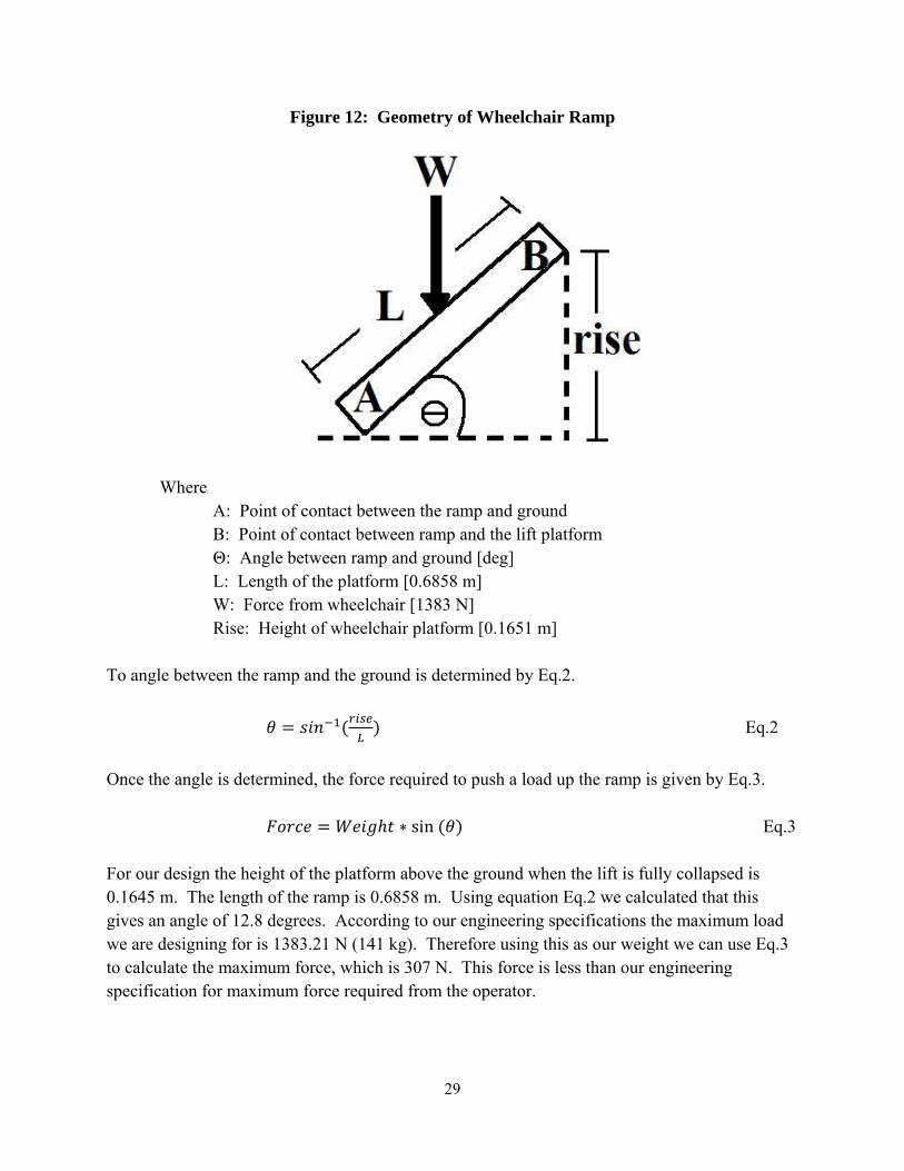
Figure 12: Geometry of Wheelchair Ramp
Where A: Point of contact between the ramp and ground B: Point of contact between ramp and the lift platform Θ: Angle between ramp and ground [deg] L: Length of the platform [0.6858 m] W: Force from wheelchair [1383 N] Rise: Height of wheelchair platform [0.1651 m] To angle between the ramp and the ground is determined by Eq.2. Eq.2 Once the angle is determined, the force required to push a load up the ramp is given by Eq.3. sin Eq.3 For our design the height of the platform above the ground when the lift is fully collapsed is 0.1645 m. The length of the ramp is 0.6858 m. Using equation Eq.2 we calculated that this gives an angle of 12.8 degrees. According to our engineering specifications the maximum load we are designing for is 1383.21 N (141 kg). Therefore using this as our weight we can use Eq.3 to calculate the maximum force, which is 307 N. This force is less than our engineering specification for maximum force required from the operator.
30
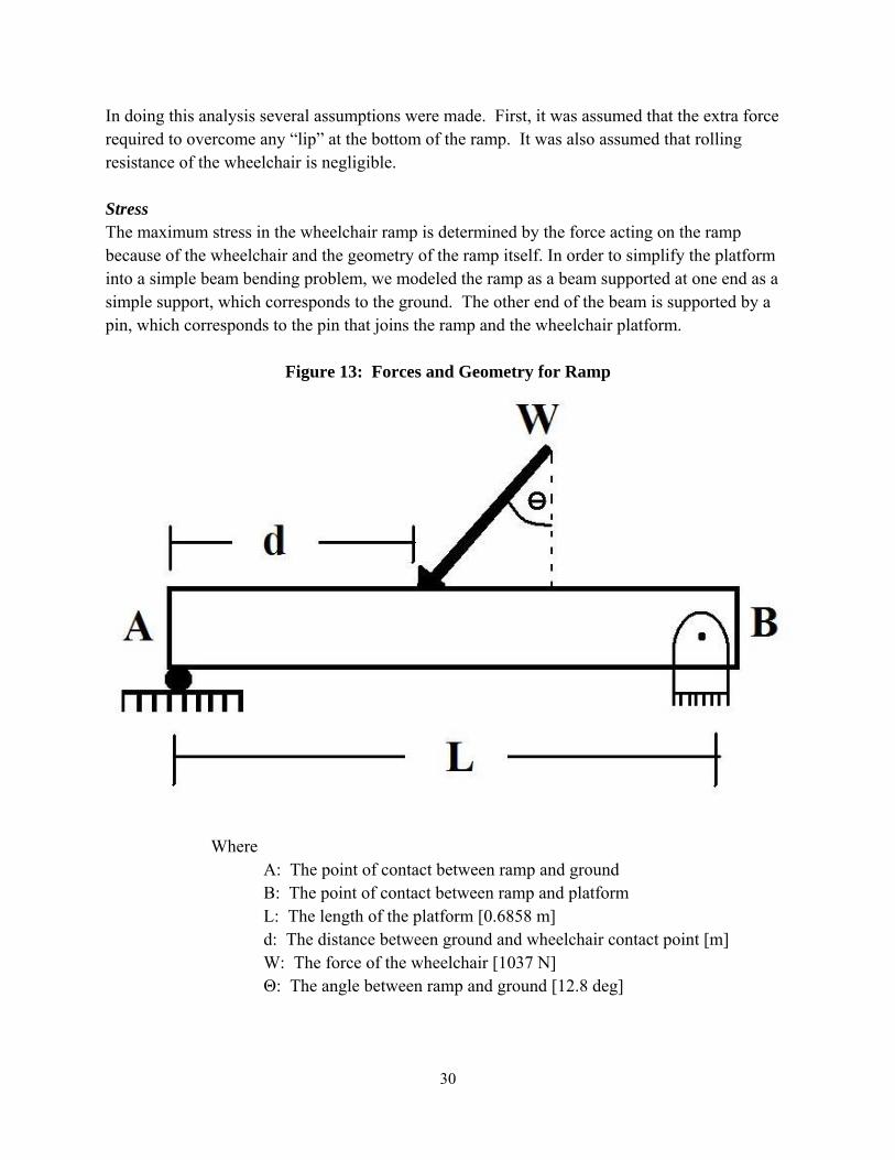
In doing this analysis several assumptions were made. First, it was assumed that the extra force required to overcome any “lip” at the bottom of the ramp. It was also assumed that rolling resistance of the wheelchair is negligible. Stress The maximum stress in the wheelchair ramp is determined by the force acting on the ramp because of the wheelchair and the geometry of the ramp itself. In order to simplify the platform into a simple beam bending problem, we modeled the ramp as a beam supported at one end as a simple support, which corresponds to the ground. The other end of the beam is supported by a pin, which corresponds to the pin that joins the ramp and the wheelchair platform.
Figure 13: Forces and Geometry for Ramp
Where A: The point of contact between ramp and ground B: The point of contact between ramp and platform L: The length of the platform [0.6858 m] d: The distance between ground and wheelchair contact point [m] W: The force of the wheelchair [1037 N] Θ: The angle between ramp and ground [12.8 deg]

31
W was calculated by taking the weight we are designing for (1383 N) and dividing it by two since each ramp will have to take half of the overall weight. This was then multiplied by a safety factor of 1.5 to get 1037 N. The maximum stress in the ramp is going to occur where the bending moment is a maximum. This occurs where W is acting on the ramp, and when d is equal to L/2. For further confirmation of this, see Appendix F.1. As shown in Appendix F.1 the maximum moment acting on the ramp is given by equations Eq.4.
Eq.4 By applying the values mentioned above for W, θ, and L we get a maximum moment of 169.8 Nm. Next we calculated the moment of inertia for the ramp. This was done using the assumptions that the ramp is a U shaped channel, like that in Figure 14.
Figure 14: Ramp Cross-Section used for Moment of Inertia Calculation
Where h1: height of vertical sections [0.0445 m] t1: width of vertical sections [0.00476 m] C1: location of centroid of vertical sections (h1/2) h2: height of horizontal section [0.003175 m] t1: width of horizontal section [0.117475 m] C2: location of centroid of horizontal section C3: location of centroid of vertical section [h1/2] C0: location of centroid of entire cross section [m] To calculate the moment of inertia (I) we first calculated the location of the C0 using Eq.5.
0 2 1 2
2 1 2 Eq.5
Where: A1: area of vertical sections (h1*t1) A2: area of horizontal section (h2*t2)

32
We then found the moment of inertia by applying the parallel axis theorem as seen in Eq.6
0 2 1 1 | 1 0| 2 2 | 2 0| Eq.6 Where I0: total moment of inertia [ ] I1 = 1 1 and I2 = 2 2 We found the total moment of inertia for the cross section to be 9.98e-8 . Once this was calculated, we were set to calculate the maximum stress in the ramp. This was done using Eq.7.
Eq.7 Where y: distance from centroid C0 to edge of vertical section [0.0319 m] We calculated that the stress the ramp will have to withstand for these conditions is 54 MPa. This is a safety factor of 4 below the yield strength of 6061 aluminum, which is 193 MPa, and therefore our will not fail. All of the above calculations were combined in the MATLAB script found in Appendix P.2 in order to expedite calculations. Platform Stresses We had to determine the stresses that will occur on the two platforms when the wheelchair is sitting on them. There are two key areas that we looked at were the bending of the platform along its length and the bending of the bottom portion of the U-channel between the vertical sections. Bending along length To model the bending stress along the length of the platform we modeled it as a beam bending problem with two simple supports in the middle. This can be seen in Figure 15.
33
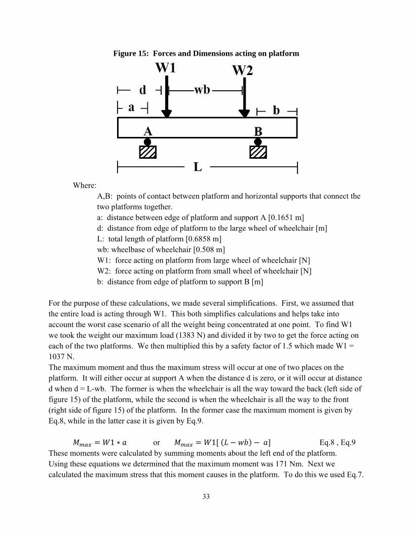
Figure 15: Forces and Dimensions acting on platform
Where: A,B: points of contact between platform and horizontal supports that connect the two platforms together. a: distance between edge of platform and support A [0.1651 m] d: distance from edge of platform to the large wheel of wheelchair [m] L: total length of platform [0.6858 m] wb: wheelbase of wheelchair [0.508 m] W1: force acting on platform from large wheel of wheelchair [N] W2: force acting on platform from small wheel of wheelchair [N] b: distance from edge of platform to support B [m] For the purpose of these calculations, we made several simplifications. First, we assumed that the entire load is acting through W1. This both simplifies calculations and helps take into account the worst case scenario of all the weight being concentrated at one point. To find W1 we took the weight our maximum load (1383 N) and divided it by two to get the force acting on each of the two platforms. We then multiplied this by a safety factor of 1.5 which made W1 = 1037 N. The maximum moment and thus the maximum stress will occur at one of two places on the platform. It will either occur at support A when the distance d is zero, or it will occur at distance d when d = L-wb. The former is when the wheelchair is all the way toward the back (left side of figure 15) of the platform, while the second is when the wheelchair is all the way to the front (right side of figure 15) of the platform. In the former case the maximum moment is given by Eq.8, while in the latter case it is given by Eq.9. 1 or 1 Eq.8 , Eq.9 These moments were calculated by summing moments about the left end of the platform. Using these equations we determined that the maximum moment was 171 Nm. Next we calculated the maximum stress that this moment causes in the platform. To do this we used Eq.7.
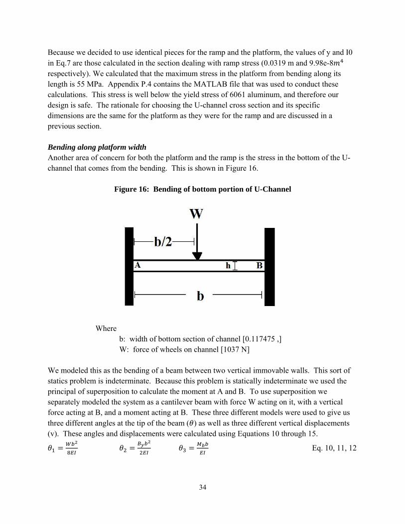
34
Because we decided to use identical pieces for the ramp and the platform, the values of y and I0 in Eq.7 are those calculated in the section dealing with ramp stress (0.0319 m and 9.98e-8 respectively). We calculated that the maximum stress in the platform from bending along its length is 55 MPa. Appendix P.4 contains the MATLAB file that was used to conduct these calculations. This stress is well below the yield stress of 6061 aluminum, and therefore our design is safe. The rationale for choosing the U-channel cross section and its specific dimensions are the same for the platform as they were for the ramp and are discussed in a previous section. Bending along platform width Another area of concern for both the platform and the ramp is the stress in the bottom of the U-channel that comes from the bending. This is shown in Figure 16.
Figure 16: Bending of bottom portion of U-Channel
Where b: width of bottom section of channel [0.117475 ,] W: force of wheels on channel [1037 N] We modeled this as the bending of a beam between two vertical immovable walls. This sort of statics problem is indeterminate. Because this problem is statically indeterminate we used the principal of superposition to calculate the moment at A and B. To use superposition we separately modeled the system as a cantilever beam with force W acting on it, with a vertical force acting at B, and a moment acting at B. These three different models were used to give us three different angles at the tip of the beam ( ) as well as three different vertical displacements (v). These angles and displacements were calculated using Equations 10 through 15.
Eq. 10, 11, 12
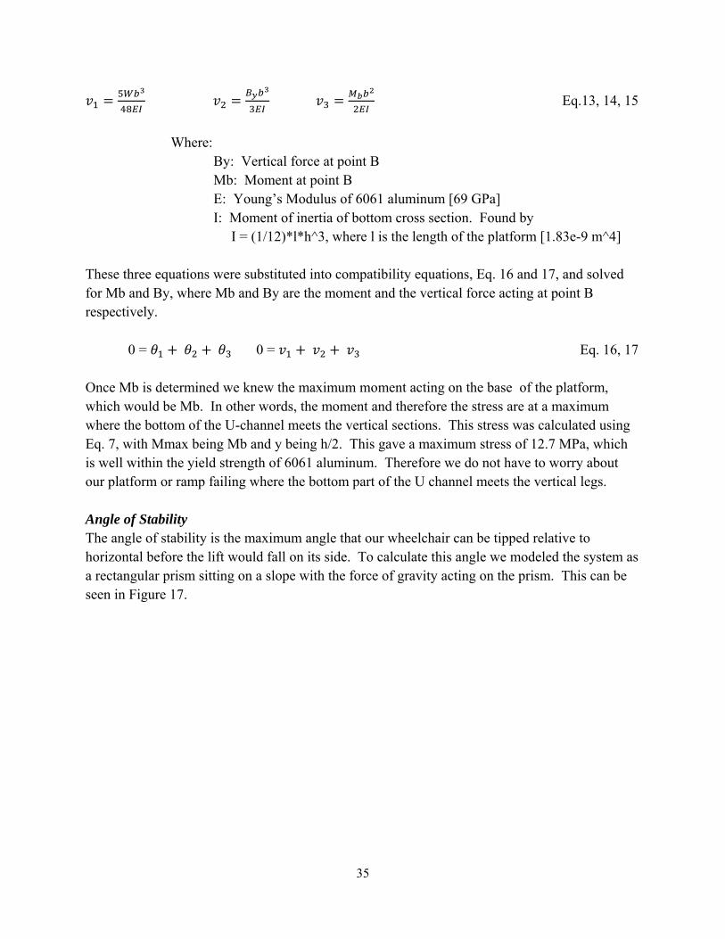
35
Eq.13, 14, 15 Where: By: Vertical force at point B Mb: Moment at point B E: Young’s Modulus of 6061 aluminum [69 GPa] I: Moment of inertia of bottom cross section. Found by I = (1/12)*l*h^3, where l is the length of the platform [1.83e-9 m^4] These three equations were substituted into compatibility equations, Eq. 16 and 17, and solved for Mb and By, where Mb and By are the moment and the vertical force acting at point B respectively. 0 = 0 = Eq. 16, 17 Once Mb is determined we knew the maximum moment acting on the base of the platform, which would be Mb. In other words, the moment and therefore the stress are at a maximum where the bottom of the U-channel meets the vertical sections. This stress was calculated using Eq. 7, with Mmax being Mb and y being h/2. This gave a maximum stress of 12.7 MPa, which is well within the yield strength of 6061 aluminum. Therefore we do not have to worry about our platform or ramp failing where the bottom part of the U channel meets the vertical legs. Angle of Stability The angle of stability is the maximum angle that our wheelchair can be tipped relative to horizontal before the lift would fall on its side. To calculate this angle we modeled the system as a rectangular prism sitting on a slope with the force of gravity acting on the prism. This can be seen in Figure 17.
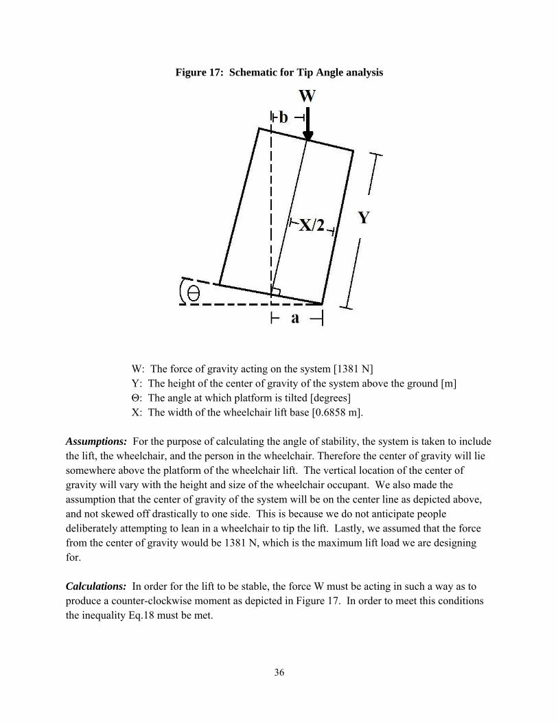
36
Figure 17: Schematic for Tip Angle analysis
W: The force of gravity acting on the system [1381 N] Y: The height of the center of gravity of the system above the ground [m]
Θ: The angle at which platform is tilted [degrees] X: The width of the wheelchair lift base [0.6858 m].
Assumptions: For the purpose of calculating the angle of stability, the system is taken to include the lift, the wheelchair, and the person in the wheelchair. Therefore the center of gravity will lie somewhere above the platform of the wheelchair lift. The vertical location of the center of gravity will vary with the height and size of the wheelchair occupant. We also made the assumption that the center of gravity of the system will be on the center line as depicted above, and not skewed off drastically to one side. This is because we do not anticipate people deliberately attempting to lean in a wheelchair to tip the lift. Lastly, we assumed that the force from the center of gravity would be 1381 N, which is the maximum lift load we are designing for. Calculations: In order for the lift to be stable, the force W must be acting in such a way as to produce a counter-clockwise moment as depicted in Figure 17. In order to meet this conditions the inequality Eq.18 must be met.

37
Eq.18 Where Eq.19, Eq. 20 As we can see from the previous two equations, three parameters determine at what point the lift becomes unstable: X (the width of the base), Y (the height of the center of gravity), and θ (the angle at which the lift is being tipped). X is 0.6858 meters and is determined by the minimum size of the base of our lift, which is in turn determined by the size of the air jack and the scissor linkages. Y will be at least 1.0668 meters (the fully extended height of the lift plus the seat height of the wheelchair), but could be up to 2.2 meters if the person sitting in the wheelchair is tall (2 meters). Therefore we calculated what values of θ are achieved for center of gravity ranging from 1.0688 to 2.2. These calculations were done using Eq.18, Eq.19, and Eq.20. To expedite calculations we used the MATLAB script found in Appendix P.1
Figure 18: Center of Gravity vs. Stability Angle
As we can see in Figure 18, the Maximum Angle of Stability exceeds our engineering specification of 7.5 degrees in even the worst case scenario. When the center of gravity is a full 2.2 meters off of the ground the angle of stability is 8.13 degrees. Therefore, it appears that stability will not be a problem for our wheelchair lift. Indeed, we could make the base of the lift even narrower and still meet our stability criteria. However, because of the placement of the Air jack 0.6858 m is the narrowest we can make the base. Bending Moment in Linkage Connector Slot The scissor linkages of our wheelchair take on a significant portion of the load. It is important for us to design this part to be able to withstand the bending moment created by the lateral forces
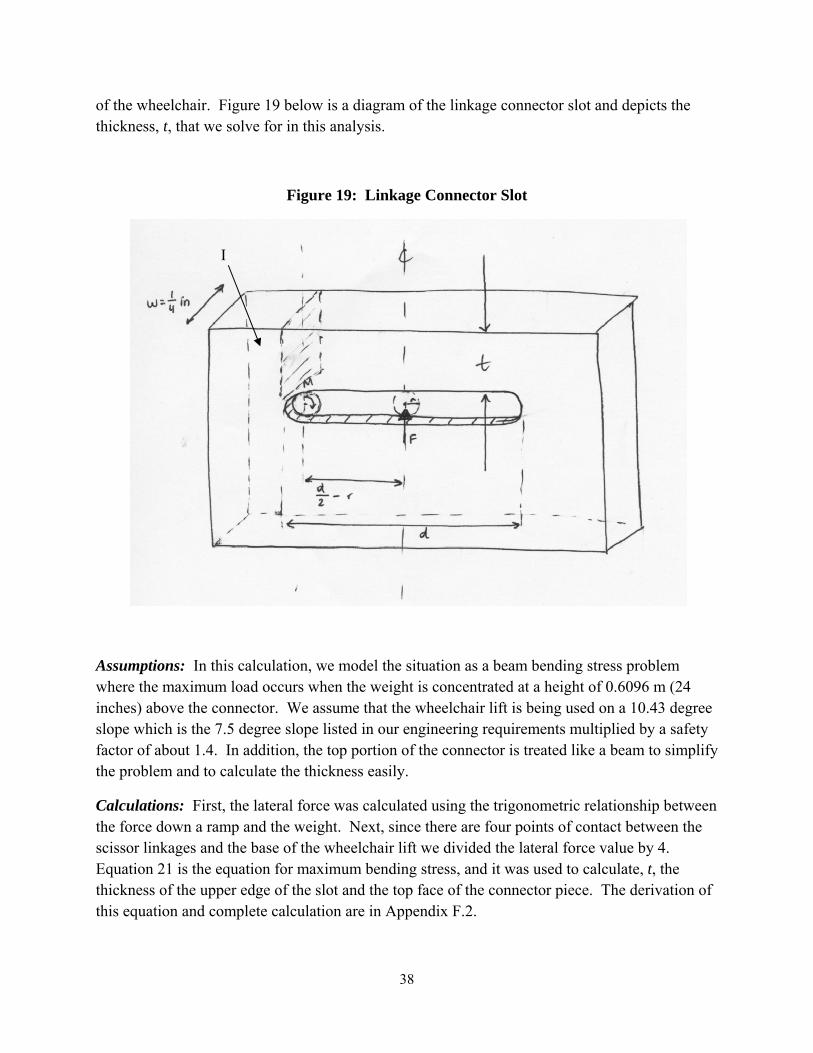
38
of the wheelchair. Figure 19 below is a diagram of the linkage connector slot and depicts the thickness, t, that we solve for in this analysis.
Figure 19: Linkage Connector Slot
Assumptions: In this calculation, we model the situation as a beam bending stress problem where the maximum load occurs when the weight is concentrated at a height of 0.6096 m (24 inches) above the connector. We assume that the wheelchair lift is being used on a 10.43 degree slope which is the 7.5 degree slope listed in our engineering requirements multiplied by a safety factor of about 1.4. In addition, the top portion of the connector is treated like a beam to simplify the problem and to calculate the thickness easily.
Calculations: First, the lateral force was calculated using the trigonometric relationship between the force down a ramp and the weight. Next, since there are four points of contact between the scissor linkages and the base of the wheelchair lift we divided the lateral force value by 4. Equation 21 is the equation for maximum bending stress, and it was used to calculate, t, the thickness of the upper edge of the slot and the top face of the connector piece. The derivation of this equation and complete calculation are in Appendix F.2.
I
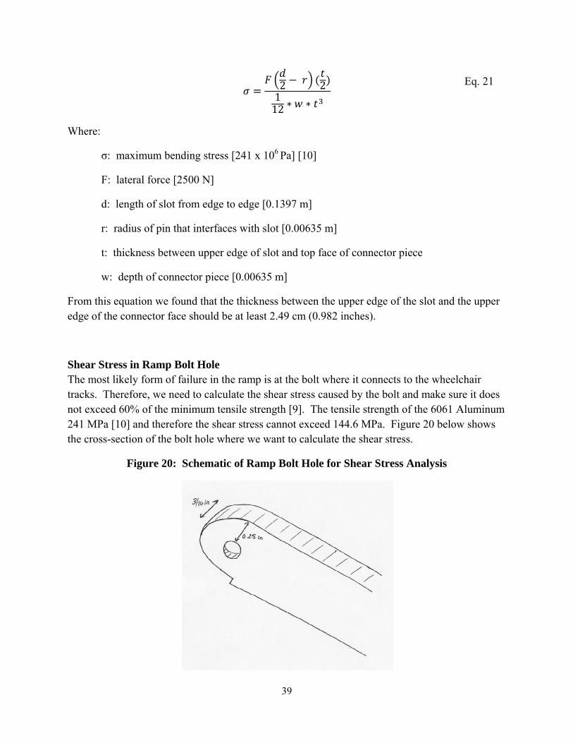
39
2 2112
Where:
σ: maximum bending stress [241 x 106 Pa] [10]
F: lateral force [2500 N]
d: length of slot from edge to edge [0.1397 m]
r: radius of pin that interfaces with slot [0.00635 m]
t: thickness between upper edge of slot and top face of connector piece
w: depth of connector piece [0.00635 m]
From this equation we found that the thickness between the upper edge of the slot and the upper edge of the connector face should be at least 2.49 cm (0.982 inches).
Shear Stress in Ramp Bolt Hole The most likely form of failure in the ramp is at the bolt where it connects to the wheelchair tracks. Therefore, we need to calculate the shear stress caused by the bolt and make sure it does not exceed 60% of the minimum tensile strength [9]. The tensile strength of the 6061 Aluminum 241 MPa [10] and therefore the shear stress cannot exceed 144.6 MPa. Figure 20 below shows the cross-section of the bolt hole where we want to calculate the shear stress.
Figure 20: Schematic of Ramp Bolt Hole for Shear Stress Analysis
Eq. 21
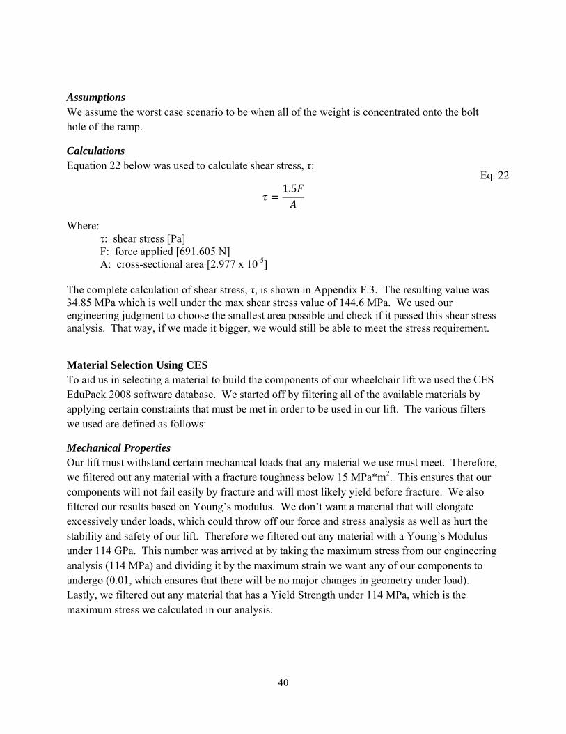
40
Assumptions We assume the worst case scenario to be when all of the weight is concentrated onto the bolt hole of the ramp.
Calculations Equation 22 below was used to calculate shear stress, τ:
1.5
Where: τ: shear stress [Pa] F: force applied [691.605 N]
A: cross-sectional area [2.977 x 10⁻⁵] The complete calculation of shear stress, τ, is shown in Appendix F.3. The resulting value was 34.85 MPa which is well under the max shear stress value of 144.6 MPa. We used our engineering judgment to choose the smallest area possible and check if it passed this shear stress analysis. That way, if we made it bigger, we would still be able to meet the stress requirement.
Material Selection Using CES To aid us in selecting a material to build the components of our wheelchair lift we used the CES EduPack 2008 software database. We started off by filtering all of the available materials by applying certain constraints that must be met in order to be used in our lift. The various filters we used are defined as follows:
Mechanical Properties Our lift must withstand certain mechanical loads that any material we use must meet. Therefore, we filtered out any material with a fracture toughness below 15 MPa*m2. This ensures that our components will not fail easily by fracture and will most likely yield before fracture. We also filtered our results based on Young’s modulus. We don’t want a material that will elongate excessively under loads, which could throw off our force and stress analysis as well as hurt the stability and safety of our lift. Therefore we filtered out any material with a Young’s Modulus under 114 GPa. This number was arrived at by taking the maximum stress from our engineering analysis (114 MPa) and dividing it by the maximum strain we want any of our components to undergo (0.01, which ensures that there will be no major changes in geometry under load). Lastly, we filtered out any material that has a Yield Strength under 114 MPa, which is the maximum stress we calculated in our analysis.
Eq. 22
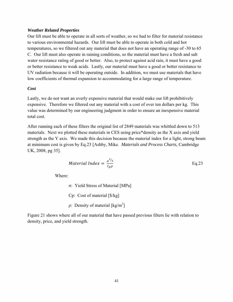
41
Weather Related Properties Our lift must be able to operate in all sorts of weather, so we had to filter for material resistance to various environmental hazards. Our lift must be able to operate in both cold and hot temperatures, so we filtered out any material that does not have an operating range of -30 to 65 C. Our lift must also operate in raining conditions, so the material must have a fresh and salt water resistance rating of good or better. Also, to protect against acid rain, it must have a good or better resistance to weak acids. Lastly, our material must have a good or better resistance to UV radiation because it will be operating outside. In addition, we must use materials that have low coefficients of thermal expansion to accommodating for a large range of temperature.
Cost
Lastly, we do not want an overly expensive material that would make our lift prohibitively expensive. Therefore we filtered out any material with a cost of over ten dollars per kg. This value was determined by our engineering judgment in order to ensure an inexpensive material total cost.
After running each of these filters the original list of 2849 materials was whittled down to 513 materials. Next we plotted these materials in CES using price*density as the X axis and yield strength as the Y axis. We made this decision because the material index for a light, strong beam at minimum cost is given by Eq.23 [Ashby, Mike. Materials and Process Charts, Cambridge UK, 2008, pg 35].
Eq.23
Where:
σ: Yield Stress of Material [MPa]
Cp: Cost of material [$/kg]
ρ: Density of material [kg/m3]
Figure 21 shows where all of our material that have passed previous filters lie with relation to density, price, and yield strength.

42
Figure 21: Aluminum and Martensitic Steel Best Satisfy Material Index for strong, cost effective beam
The slope of the guide line (bottom right corner) is 1.5. This is determined from the exponent on the σ in the material index. If we move the guide line so that it has a large Y intercept, we can eliminate more materials that are not as effective at meeting our material index criteria. This will eliminate all of the copper based compounds in the lower left hand corner, as well as some of the stainless steels and a few aluminum alloys. What is left is mostly Martensitic steels and aluminum alloys of the 2xxx, 6xxx, and 7xxx series. Any of these would meet our selection criteria for our material.
In the end, we chose to uniformly go with 6061 aluminum alloy for all of our lift pieces. The reasons for this are as follows. 6061 aluminum is a fairly common and standard aluminum alloy and thus is made in a much greater variety of geometries than the other series. Therefore it will be easier to get off the shelf raw stock from McMaster-Carr in the shapes and dimensions we want if we use 6061 aluminum. Secondly, 6061 aluminum is easy to machine when compared to 2xxx, 7xxx aluminum and especially martensitic steel. This will make the manufacturing process go much more smoothly. Lastly, 6061 aluminum stock is actually significantly cheaper than other the other aluminum alloys on the McMaster-Carr website.

43
Design for the Environment Using SimaPro, we evaluated the environmental impact of our prototype. By imputing the material type and total mass, we plotted the total emission mass breakdown in grams (See Appendix R.1). We found that 23kg of 6060 Aluminum would produce 4,215,567 grams of raw emissions, 221177 grams of air emissions, 3214 grams of water emissions and 30937 grams of waste emissions. To get a better idea of how these figures match up with other materials, we similarly plotted the values for 23 kg of Titanium. 6060 Aluminum produces a larger amount of emissions and therefore, is the worse choice between the two materials. We also generated characterization, normalization, and single score graphs to see how the Aluminum compared to Titanium. These graphs are found in Appendix R.1, R.2, and R.3. Despite the excessive emissions created by Aluminum we chose it as our material after using CES software to find a strong but lightweight material. In addition, we took cost into consideration and therefore, had to find a commonly sold material. Lastly, with limited machine time, we chose a material that we knew would be easy to work with during milling, drilling and welding processes.
One environmental hazard of our prototype is the concentrated exhaust fumes that build up in the air jack. Obviously, since it is the source of inflation of the air jack, we cannot do without it. However, when the bag is deflated operators should take precaution and make sure to release the exhaust away from them. The use of the air jack does not create any extra air pollution that a car would create on its own; we just need to make sure that operators do not breathe in the concentrated fumes.
Failure/Safety Analysis using Failure Mode and Effect Analysis (FMEA) We performed a Failure Mode Engineering Analysis (FMEA) on our wheelchair lift to help us identify potential trouble areas for our design. The complete analysis can be found in Appendix S.1. After conducting the analysis we found that the base of our wheelchair lift is the area most prone to failure. Specifically, we could have major problems with the base becoming unstable and deforming. Indeed, during out validation testing we found that this was the number one issue with our lift. This could be fixed in subsequent iterations by redesigning the base to be stiffer. The current design is just a series of flat 1/8 inch plates welded together which does not provide much torsional rigidity. Making the base a boxed section would drastically increase the base’s moment of inertia and make it more stable while in operation
The second biggest area of concern according to the FMEA is the air jack itself. The jack may be prone to puncture and rapid loss of air, which will render the lift unusable and may cause injury to the user if it deflates too quickly. There are several things that we could do to help mitigate the consequences of air jack failure. One thing we could do is redesign the base so that no part of the air jack ever rests on the ground. This eliminates the possibility of the jack being rested on something sharp and being punctured. We could also add a dampening mechanism to the scissor linkages that would slow down the descent of the lift in case of air jack failure.

44
The final major area of concern the FMEA brought up was the sliders and pivots for the scissor linkage mechanism. Specifically failure to properly keep these parts well lubricated can cause the lift to rise unevenly, creating stress in other parts of the lift as well as creating an uncomfortable ride. We also determined that it is fairly hard to determine how well lubricated the joints are because it doesn’t reveal itself on a cursory visual inspection. We can improve this by using a heavier lubricant, such as axle grease, for our joints instead of the WD-40 we are currently using. Furthermore, we could coat the parts in question in Teflon to ensure a low coefficient of friction even without lubrication.
FINAL DESIGN Based on the conclusions we reached from our analysis, we have created our final design which can be seen in Figure 22 below. Refer to Appendix G for the final design assembly drawing with dimensions. This final design can be broken down into five main sections being the base piece, scissor mechanism, platform/ramp, securing mechanism, and air jack. The following body will outline these five sections, and also describe additional components that bring everything together. We will also discuss how to operate the wheelchair lift and list all components in a bill of materials.
Figure 22: Final Design
Base Piece
Air Jack
Scissor Mechanism
Platform
Ramp
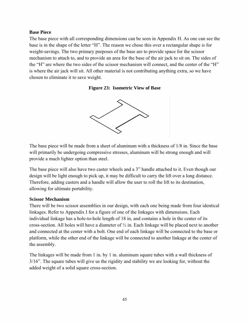
45
Base Piece The base piece with all corresponding dimensions can be seen in Appendix H. As one can see the base is in the shape of the letter “H”. The reason we chose this over a rectangular shape is for weight-savings. The two primary purposes of the base are to provide space for the scissor mechanism to attach to, and to provide an area for the base of the air jack to sit on. The sides of the “H” are where the two sides of the scissor mechanism will connect, and the center of the “H” is where the air jack will sit. All other material is not contributing anything extra, so we have chosen to eliminate it to save weight.
Figure 23: Isometric View of Base
The base piece will be made from a sheet of aluminum with a thickness of 1/8 in. Since the base will primarily be undergoing compressive stresses, aluminum will be strong enough and will provide a much lighter option than steel.
The base piece will also have two caster wheels and a 3” handle attached to it. Even though our design will be light enough to pick up, it may be difficult to carry the lift over a long distance. Therefore, adding casters and a handle will allow the user to roll the lift to its destination, allowing for ultimate portability.
Scissor Mechanism There will be two scissor assemblies in our design, with each one being made from four identical linkages. Refer to Appendix I for a figure of one of the linkages with dimensions. Each individual linkage has a hole-to-hole length of 18 in, and contains a hole in the center of its cross-section. All holes will have a diameter of ½ in. Each linkage will be placed next to another and connected at the center with a bolt. One end of each linkage will be connected to the base or platform, while the other end of the linkage will be connected to another linkage at the center of the assembly.
The linkages will be made from 1 in. by 1 in. aluminum square tubes with a wall thickness of 3/16”. The square tubes will give us the rigidity and stability we are looking for, without the added weight of a solid square cross-section.
46
Figure 24: Isometric View of Scissor Linkage
One side of each scissor assembly will be connected to pins at the base and platform while the other side is connected to slots in which the members can slide. The scissor linkages will pivot and rotate about their centers as the platform is raised and lowered. The reason we like the scissor mechanism is because of its collapsible nature. In the fully collapsed position, the members will all be overlaying each other, and will therefore have a combined height of only ~3 in.
Platform/Ramp The platform tracks and ramps can be seen with dimensions in Appendix J and K respectively. There are two platform tracks for each of the wheels. Each of these platforms are U-shaped channels. The platforms are 5 in. wide and 27 in. long, and the walls are 1.75 in. tall. The base of the platform has a thickness of 1/8 in. while the walls have a thickness of 3/16 in. The ramps will be made from the same pieces with the same dimensions except a pivot corner is cut out with a height of 1.91 in. and a length of 2.54 in. We will apply non-skid tape to the base of both the platforms and ramps to prevent slipping of the wheelchair.
Figure 25: Isometric View of the Ramp
The two ramps will be connected through two aluminum supports that are to be welded on. Refer to Appendix L for drawings with dimensions. These two pieces will ensure the platforms are always at the same height and they will provide added stability for the lift. They will also serve as part of the material that the air jack pushes up on and connects to.
The platform and ramp will be bolted together at the end with a ½ in. diameter bolt, and the ramp will be able to pivot at this point. One of the nice features of our design is that the ramp will fold

47
down onto the platform when the lift is ready to be transported. This will allow us to provide a longer, low-sloping ramp for the wheelchair to get onto the lift, while still staying within the required compacted dimensions.
Securing Mechanisms Our final design incorporates two kinds of securing mechanisms. The first consists of depressions in the platform, and the second consists of airplane seatbelts which can be seen in Figure 26 below. The depressions help keep the wheelchair from rolling back and forth, but the two airplane seatbelts around the rear wheels are what really guarantee the wheelchair to stay on the lift. The seatbelts clip together easily, and are adjustable to guarantee a snug fit on wheelchair wheels of all sizes. The seatbelts will attach to slots in the bottom of the platform tracks where the rear wheels sit, and there will be two seatbelts total.
As part of our platforms for the final design, we wanted to have depressions for the front and back wheels to minimize forward or backward rolling during operation. The best way to manufacture these depressions is by stamping the metal, but we do not have stamping capabilities in our machine shop. Therefore, for our prototype design we will use straight, flat aluminum channels.
The depressions are a nice feature to have, but they are not part of the fundamental operation of our lift. They help keep the wheelchair more stable during operation but we have another locking mechanism that is even more critical to secure the wheelchair. More importantly, the depressions do not have any effect on the validation of our design. It has no direct effect on the raising and lowering of the wheelchair which is our primary focus. It is an added feature for the customer and is not necessary for functionality, and therefore we have chosen to leave it out of our prototype.
Figure 26: Airplane seatbelts
Air Jack The air jack will provide all the lift force, and comes with an air bag, hose, and two differently-sized cones which can be seen in Appendix M. The air jack inflates easily with the vehicle’s exhaust, and this will be the primary way of raising the lift. To inflate the air jack, the user must first attach the one end of the hose to the bag, and the other end to the cone of the correct size. The user will then insert the cone over the pipe of the vehicle exhaust and start the engine. The bag will inflate and when the lift is at the correct height, the user will stop the engine and remove
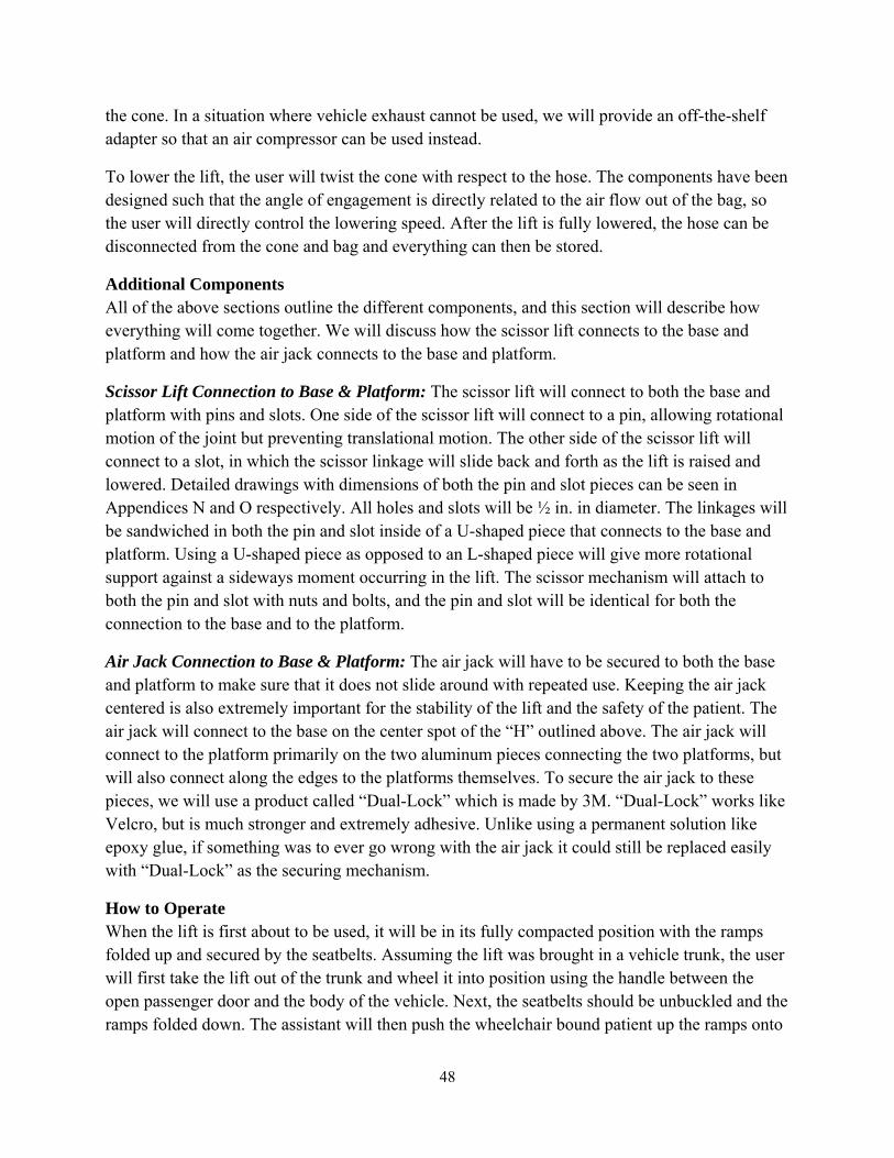
48
the cone. In a situation where vehicle exhaust cannot be used, we will provide an off-the-shelf adapter so that an air compressor can be used instead.
To lower the lift, the user will twist the cone with respect to the hose. The components have been designed such that the angle of engagement is directly related to the air flow out of the bag, so the user will directly control the lowering speed. After the lift is fully lowered, the hose can be disconnected from the cone and bag and everything can then be stored.
Additional Components All of the above sections outline the different components, and this section will describe how everything will come together. We will discuss how the scissor lift connects to the base and platform and how the air jack connects to the base and platform.
Scissor Lift Connection to Base & Platform: The scissor lift will connect to both the base and platform with pins and slots. One side of the scissor lift will connect to a pin, allowing rotational motion of the joint but preventing translational motion. The other side of the scissor lift will connect to a slot, in which the scissor linkage will slide back and forth as the lift is raised and lowered. Detailed drawings with dimensions of both the pin and slot pieces can be seen in Appendices N and O respectively. All holes and slots will be ½ in. in diameter. The linkages will be sandwiched in both the pin and slot inside of a U-shaped piece that connects to the base and platform. Using a U-shaped piece as opposed to an L-shaped piece will give more rotational support against a sideways moment occurring in the lift. The scissor mechanism will attach to both the pin and slot with nuts and bolts, and the pin and slot will be identical for both the connection to the base and to the platform.
Air Jack Connection to Base & Platform: The air jack will have to be secured to both the base and platform to make sure that it does not slide around with repeated use. Keeping the air jack centered is also extremely important for the stability of the lift and the safety of the patient. The air jack will connect to the base on the center spot of the “H” outlined above. The air jack will connect to the platform primarily on the two aluminum pieces connecting the two platforms, but will also connect along the edges to the platforms themselves. To secure the air jack to these pieces, we will use a product called “Dual-Lock” which is made by 3M. “Dual-Lock” works like Velcro, but is much stronger and extremely adhesive. Unlike using a permanent solution like epoxy glue, if something was to ever go wrong with the air jack it could still be replaced easily with “Dual-Lock” as the securing mechanism.
How to Operate When the lift is first about to be used, it will be in its fully compacted position with the ramps folded up and secured by the seatbelts. Assuming the lift was brought in a vehicle trunk, the user will first take the lift out of the trunk and wheel it into position using the handle between the open passenger door and the body of the vehicle. Next, the seatbelts should be unbuckled and the ramps folded down. The assistant will then push the wheelchair bound patient up the ramps onto

49
the platforms. The seatbelts should then be pulled through the rear wheel spokes and secured tightly. The assistant will then connect the hose to the air jack, and attach the corresponding cone attachment. At this point, the assistant will start the car and hold the cone to the exhaust of the car. When the lift is at the correct height, the cone will then be removed. The air jack will stay inflated so the assistant can then assist the patient from the wheelchair to the vehicle seat using one of the slider boards talked about above. At this point, the assistant can lower the lift by twisting off the funnel from the hose. When the air jack is fully deflated, the seatbelts can be undone and the wheelchair can be rolled back down the ramps and put in the vehicle. The ramps should then be folded back up and secured with the seatbelts. The final step will be to roll the lift back to the vehicle trunk and put in.
Another option for the users is to use an air compressor with the air jack adapter instead of using the vehicle exhaust with the cone. All operations will be the same as described above except for the inflation step.
Bill of Materials The bill of materials for our lift can be found in Appendix Q. It lists all components that are needed to make one of our lifts. The aluminum purchases from McMaster-Carr are all raw material that require further machining while everything else is off-the-shelf.
MANUFACTURING PLAN In this section we will describe our manufacturing plan by highlighting the key components of our design and how they will be manufactured. We interviewed Bob Coury at the Undergraduate machine shop to understand what manufacturing processes were available to us. Since we machined only one material, T6061 Aluminum, the machining speeds were constant for almost the entire process. We used the band saw at 290 RPM to cut all of our aluminum parts. All end mill and drill processes were performed with a 1200 RPM machine speed.
Ramps and Tracks We manufactured the ramps and tracks from two U-Channel blocks of T6061 aluminum ordered from McMaster-Carr (Part #1630T19). We used a band saw to cut the pieces into four 27” pieces and to cut 1” off of the leg length of all 4 pieces. For the ramps only we cut out notched sections using the band saw. This allowed the ramps to fold down. We also used a used a 1/2” end mill to remove 1/8” off the thickness of both ramp U-channel legs. We used a manual-fed mill with a 3/8” end mill to finish all the edges of both pieces in one pass. We used an automatic-feed mill with single point fly cutter set to 600 RPM to shave 1/16” off of the underside of all of the U-channels. This took 6 passes at a feed of 3 IPM. Next, we welded aluminum blocks to one end of the two platforms. We then drilled ¼” holes in the U-channels. This was done using a 3/16” drill and a .249” ream set to 100 RPM. Next, two shoulder bolts are set to fix the ramp to the tracks. We were unable to find the correct length of bolt, so we used four non-hardened bolts and cut them to the correct size with a hacksaw. Lastly, we cleaned the

50
surfaces with acetone and affixed 3M® anti-skid tape (SKU #051131594371) to the bottom-inside tracks of the U-channels.
Scissor Linkages We started with two lengths of boxed lengths 1 “by 1” with uniform wall thickness 3/16” ordered from McMaster-Carr (Part #6546K343). We cut these into 8 20” lengths with a band saw. For each piece, we drilled ¼” diameter holes 1” away from each end and in the center of each link. We drilled the holes on each link individually using a mill. For each hole, we used a center drill to mark each hole, a 3/16” drill, and a .249” ream set to 100 RPM. Once all the holes were drilled, we rounded the edges of each linkage using a rotary sander. We used permanent marker, a scribe and a 1” diameter washer to mark the ends to be rounded.
Pin Joints We manufactured the pin joints from rounded L-channel stock ordered from McMaster-Carr (Part #8982K364). We cut off eight 2.5” lengths using the band saw set at 290 RPM. We then drilled one ¼” hole 1 .25” from the edge and 1.25” from the bottom using a mill. Once again, we used a 3/16” drill followed by a .249 ream set at 100 RPM.
Slot Joints We manufactured the pin joints from the same rounded L stock as the pin joints described above (Part #8982K364). We cut off eight 7.5” lengths using a band saw. We squared off the length edges using a 3/8” end mill. We used an edge finder tool on the mill to pinpoint the beginning of the slot. To create the slots, we used a 3/16” end mill at 1200 RPM to drill a hole through the piece 11.25” from the bottom and 1.25” from the end of the length. We repeatedly drilled holes along the length using the mill until the slot was 5 in long. We then moved the shifted the mill up 1/32” and climb-milled along the length of the slot. Lastly, we climb-milled 1/32” from the bottom of the slot to create a 1/4” slot.
Base and Supports The base and supports were the easiest to make. We used 1/8’’ thick and 4” wide sheet aluminum ordered from McMaster-Carr (Part #8975K418) for the platforms that would hold the scissor linkages. The supports at the bottom of our device were created from 1/8” thick and 2” ordered from McMaster-Carr (Part #8975K19) wide sheet aluminum. We cut the 4 in wide sheets into two 27” lengths using the band saw. For the base supports, we cut out three 21” lengths using the band saw. For the top supports, we cut three 29” lengths using the band saw.
Air Jack We purchased a Titan© Exhaust Air Jack(Model# TTC-3.0) from Northern Tool Company. We are using Velcro to secure the jack to the base and to the supporting bars that ensure the jack lifts uniformly. Using Velcro makes the balloon easily replaceable in case of failure of some kind.

51
Spacers We found that when the lift was fully collapsed the scissor linkages rested on the corners of the slot joints. This was not desirable because the slot joint was not made to handle that much force. To compensate for this problem we created 2 aluminum spaces out of scrap metal. These spacers were cut on the band saw to 2”x1”5/8’’ size and attached with epoxy to the top side of the scissor linkages, centered on the linkages center pin joint.
Seatbelts For the seatbelts, we originally wanted to affix them to the frame using epoxy, but we were unsure how the adhesive would hold in extreme cold conditions. Instead we decided to affixed the female end of the belts to the outer-center of the tracks using Velcro. In the future, we would recommend creating a compliant locking mechanism to secure the wheelchair wheels.
Handle To create the handle, we started with a 90 degree aluminum bar ordered from McMaster-Carr (Part #8982K912). We cut the part down to 29” using the band saw and welded it to the front of the base, where the ramps unfold to. We then attached a pre fabricated handle to the aluminum bar with a set of screws set into holes we had drilled out with a hand held drill and ¼’’ drill bit.
Casters To attach the casters, we started with the rounded L-channel stock used with the slot and pin joints ordered from McMaster-Carr (Part#8982K364). We than used the band saw to cut these down to the desired size. We used a mill and ¼’’ drill bit to create four holes in the L-channel stock. We used bolts ¼’’ bolts to attach the base of the castors to the L-channel stock. the stock was then welded to the base of the lift.
Assembly We began assembling the prototype by welding the base together. We butt-welded the ends of three 2’’x21” aluminum sheets to the two 4” wide aluminum sheets such that the middle of the center bar is 14.5” from the end and the top and bottom bars are 4.5” away from the center bar. In the same operation, we welded the pin joints and slot joints to the base. Two pin joint components and slot joint components are placed flush with each other to form a U-channel. Next, we pinned the scissor linkages to each other and to the base pin and slot joints using ¼” shoulder bolts with shoulder length 2”. We used nylon hex nuts on the ends of all the bolts. The slot joints and pin joints were welded onto the base with the scissor linkages still attached. This was done to make sure that the slot and pin joints lined up properly. We welded the tracks, the top supports and top pin and slot joints in the same fashion as well. To do this, we turned the entire prototype upside down and rested it on the tracks. At this point we found that the aluminum warped during the welding process. We made a single cut down the center of the bending pieces using a saber saw. We then used some of our scrap aluminum to form a spacer to re-weld the top supports in attempt to counteract this. We were able to eliminate some, but not all of the bending in the top supports. Due to time constraints, we were forced to leave it as it
52
was. We affixed Velcro® to the bottom of the top supports and top of the bottom supports. We affixed Velcro to the top and bottom of the air jack and placed it into the scissor frame. Lastly, we connected the ramps to the tracks using four nuts and bolts we cut to length with a hacksaw.
VALIDATION Testing Plans To demonstrate that our prototype meets the engineering specifications outlined in the initial phase of the project, we will conduct a series of validation tests. In order to test that the maximum weight capacity requirement is met, we will load the wheelchair lift with 141 kg and inflate the air jack to maximum height. As the bag inflates we will observe the scissor linkages, the tracks and the base to make sure there is no failure that can be seen with the naked eye. During this same test, we will use a stopwatch to measure the time it takes to extend to maximum height to ensure that it takes less than 1 minute to fully extend. Next, the maximum extension height will be measured (this value is required to be at least above 59 cm) and the weight will be lowered until the lift is fully collapsed. Again, we will measure the time it takes to return to the ground and then calculate the retraction speed by dividing the time by the maximum extension height.
A few of our engineering requirements can just be tested just by taking one simple measurement instead of conducting an involved test. For example, the footprint area can be calculated by measuring the width and height of the base. We set this target to (63.5 cm x 76.2 cm) in DR #1; however, after generating design concepts and further researching our alpha design, we chose to use 3-ton rated air jack with a 61 cm (24 inch) diameter. This diameter already takes up a large portion of our set footprint area and does not allow for enough room for our scissor linkages and the attaching members. In addition, it is not practical to meet this target if we would like to add a handle or casters to the front of our design to add to the portability of the lift. Next, the compacted dimensions should be no more than 79 x 100 x 122 cm and this will be easy to check just by taking the length, width and height measurements. Another engineering requirement for our wheelchair lift is that the total weight should be less than 23 kg. This can be easily tested by placing the collapsed lift onto a scale. We have access to a scale at the Center for Prosthetics and Orthotics where our sponsor, Dr. Leonard, works. Also, another engineering target we have set for our wheelchair lift is that the distance been the wheelchair tracks should be 48 – 61 cm; this can simply be measured from our prototype design.
Another feature of our lift that may need additional testing is the maximum angle at which the wheelchair lift can be angled at before it tips. One way to test this is to build a small ramp out of two planks of wood. They can be attached on one side with a hinge and then the angle between the two can easily be measured using a protractor. The angle can be incremented until the wheelchair starts to tip over and we will be able to say that this is the maximum angle that can be reached before the lift tips.

53
Lastly, one of our engineering targets was that the maximum force required from the operator was 445 N. With air jack design the maximum force applied by the operator is when the wheelchair patient is pushed up the ramp onto the two tracks. To calculate this force up the ramp we will have to know the angle of inclination of the ramp and then the combined weight of the wheelchair and patient. The force required to push the patient up the ramp will be the combined weight multiplied by the cosine of the angle of inclination.
After conducting this validation testing we are confident that our prototype will function according to our outlined expectations to meet both engineering targets and the customer requirements.
Test Results We validated the functionality of our wheelchair lift by testing it multiple times and using members of the team as test subjects. During the initial testing we found that our lift worked and was able to lift each of the team members to a height of more than 24 inches. To further validate the capabilities of our lift we had to revisit the engineering targets we set for our project. By taking multiple measurements of our lift while in operation and also conducting a few tests we found that our prototype met 9 of our 11 engineering targets.
To test our lift capacity we loaded our wheelchair lift with 141 kg (310 lbs) using barbell plates and our prototype could lift this amount to meet our target. To test the lowering speed of the wheelchair lift we measured the time to deflate the lift when loaded with the wheelchair and a test subject and then divided by the change distance from the max extension height to the compacted height. A deflation time of 13 seconds and a difference in height of 38.74 cm (15.25 in) results in a speed of 2.98 cm/s (1.17 in/s). This deflation speed is slower than the maximum target value of 5 cm/s and therefore, our lift deflates at a safer speed than expected and the target was met. Our target weight was 23 kg (50 lbs). After assembly was complete, we weighed our prototype and found its total weight to be 20.6 kg (45.5 lbs), which is under our weight limit. Our prototype cost was $626.48, well under our target cost of $1,375. To validate the tip angle target value of our lift we propped up one side of our lift (while loaded with wheelchair and test subject and fully extended) with barbell plates until the lift was at an angle of 7.5 degrees and then we removed all supports to see if the lift could stabilize itself. The lift immediately began to tip over and therefore, our prototype does not meet our maximum tip angle specification of 7.5 degrees.
Our lift does not meet our target footprint area of 63.5 cm x 76.2 cm (25 in x 30 in). Our prototype’s footprint area is 74 cm x 74 cm (29 in x 29 in). The footprint of our alpha design met this target value but our design evolved slightly. We widened our base to better accommodate for the 61 cm (24 in) diameter of the air jack, the scissor linkages along with connecting slot and pin components. Therefore, due to a design change our target footprint area was not met. Despite missing the footprint area target our lift met the compacted area specification, showing that it is still a portable design and can easily fit into the trunk of any
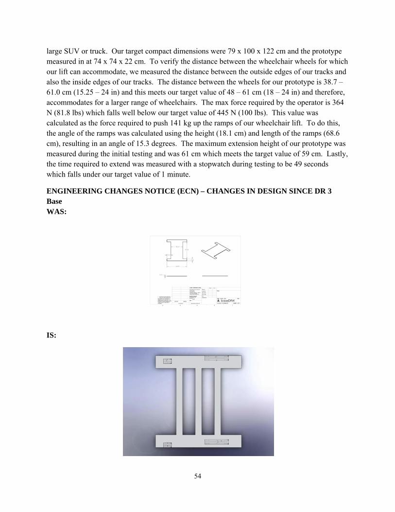
54
large SUV or truck. Our target compact dimensions were 79 x 100 x 122 cm and the prototype measured in at 74 x 74 x 22 cm. To verify the distance between the wheelchair wheels for which our lift can accommodate, we measured the distance between the outside edges of our tracks and also the inside edges of our tracks. The distance between the wheels for our prototype is 38.7 – 61.0 cm (15.25 – 24 in) and this meets our target value of 48 – 61 cm (18 – 24 in) and therefore, accommodates for a larger range of wheelchairs. The max force required by the operator is 364 N (81.8 lbs) which falls well below our target value of 445 N (100 lbs). This value was calculated as the force required to push 141 kg up the ramps of our wheelchair lift. To do this, the angle of the ramps was calculated using the height (18.1 cm) and length of the ramps (68.6 cm), resulting in an angle of 15.3 degrees. The maximum extension height of our prototype was measured during the initial testing and was 61 cm which meets the target value of 59 cm. Lastly, the time required to extend was measured with a stopwatch during testing to be 49 seconds which falls under our target value of 1 minute.
ENGINEERING CHANGES NOTICE (ECN) – CHANGES IN DESIGN SINCE DR 3 Base WAS:
IS:
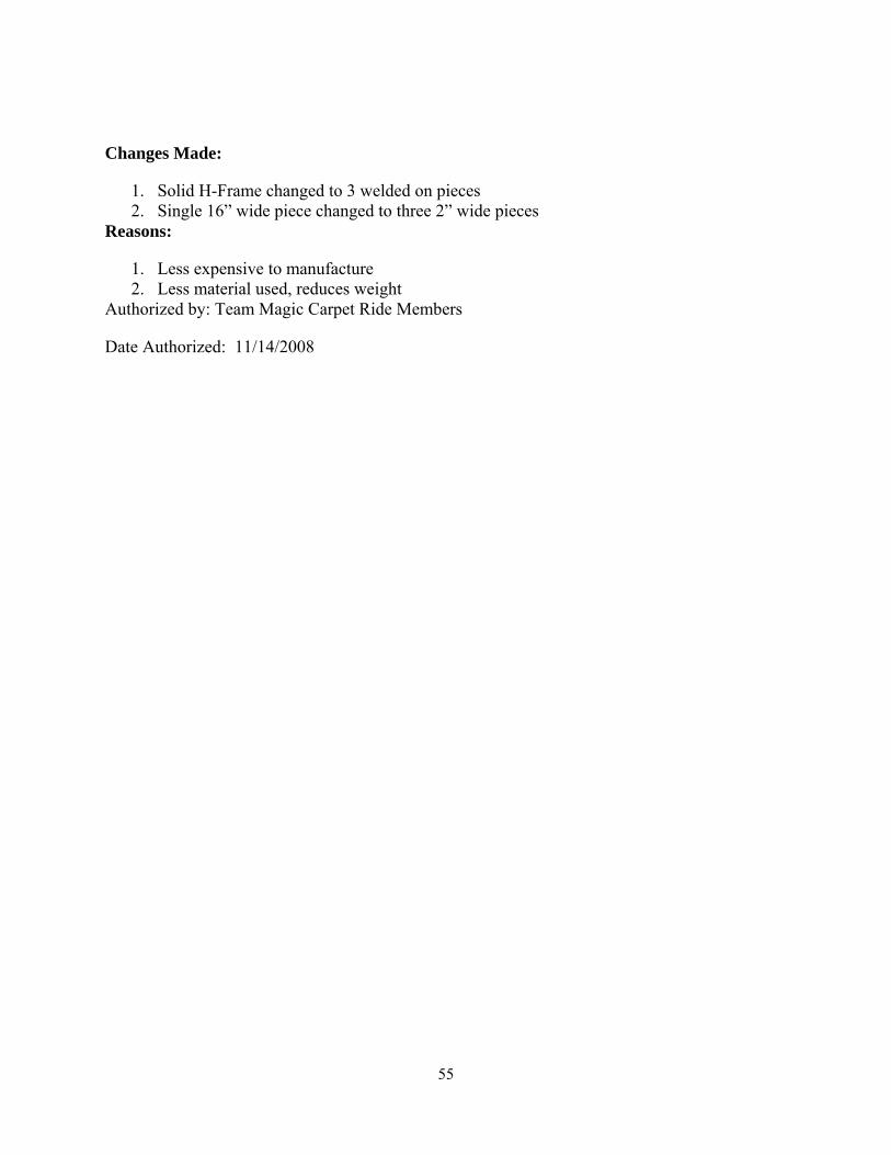
55
Changes Made:
1. Solid H-Frame changed to 3 welded on pieces 2. Single 16” wide piece changed to three 2” wide pieces
Reasons:
1. Less expensive to manufacture 2. Less material used, reduces weight
Authorized by: Team Magic Carpet Ride Members
Date Authorized: 11/14/2008

56
Pin Joint WAS:
IS:
Changes Made:
1. Pin size decreased to .25” Reasons:
1. .5” shoulder bolts unavailable. .25” bolts are usable without changing original design. Authorized by: Team Magic Carpet Ride Members
Date Authorized: 11/17/2008

57
Slot Joint WAS:
IS:
Changes Made:
1. Slot size decreased to .25” Reasons:
1. .5” shoulder bolts unavailable. .25” bolts are usable without changing original design. Authorized by: Team Magic Carpet Ride Members
Date Authorized: 11/17/2008

58
Scissor Links WAS:
IS:
Changes Made:
1. Slot size decreased to .25” Reasons:
1. .5” shoulder bolts unavailable. .25” bolts are usable without changing original design. Authorized by: Team Magic Carpet Ride Members
Date Authorized: 11/17/2008

59
Ramp WAS:
IS:
Changes Made:
1. Slot size decreased to .25” Reasons:
1. .5” shoulder bolts unavailable. .25” bolts are usable without changing original design. Authorized by: Team Magic Carpet Ride Members
Date Authorized: 11/17/200
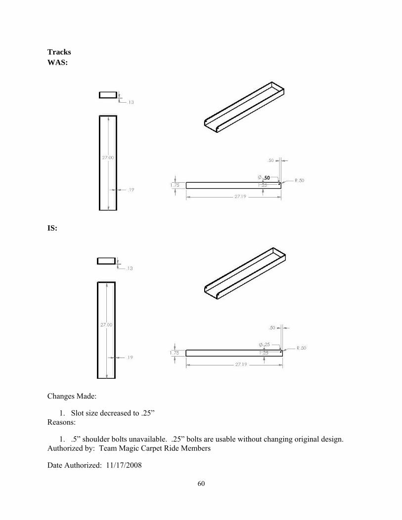
60
Tracks WAS:
IS:
Changes Made:
1. Slot size decreased to .25” Reasons:
1. .5” shoulder bolts unavailable. .25” bolts are usable without changing original design. Authorized by: Team Magic Carpet Ride Members
Date Authorized: 11/17/2008
61
DISCUSSION With any prototype in its first revision there are always areas of improvement, but we are very pleased with our prototype as a proof of concept. Our primary goal with this project was to test whether an air jack could be used as a lightweight option to power a portable wheelchair lift, and we feel we have thoroughly proved it as a viable option. The following section will outline several of the strengths of our design along with weaknesses that we found. Suggestions for improving the weaknesses are covered in the following recommendations section.
Strengths Lightweight: One of the characteristics that really makes our lift unique from everything else on the market is being lightweight. In accordance with our engineering specifications, we required a weight of under 50 lbs for ease of lifting. Our prototype came in at a final weight of 45.5 lbs. This proves that the air jack is very effective as a lightweight lifting mechanism, and aluminum is a viable material for all other components. It also showed that even though scissor mechanisms are generally heavy, we were able to use one as our supporting mechanism while still meeting the weight requirement.
Compact: With portability as one of our top focuses, we also emphasized making a lift with small compacted dimensions of 79 x 100 x 122 cm to fit inside of an SUV trunk. Our prototype came in with much smaller compact dimensions of 74 x 74 x 22 cm. Not only does our lift fit easily into an SUV trunk, we transported it numerous times in a teammate’s sedan trunk without a problem. This proves the air jack deflates to a negligible size, and the scissor mechanism serves one its main functions of compacting together nicely.
Inexpensive: One of the big drawbacks of the wheelchair lifting mechanisms out on the market right now is that they are extremely expensive. Lifts that are custom built into vehicles are tens of thousands and even a cheap one which we benchmarked was still $1375. Our goal was to have our prototype less than this value and we came in much lower at $626.48. This proves that the air jack is a cost effective alternative to pricey hydraulic systems. In addition, our prototype cost is much higher than what we would expect for a mass-produced product, especially since we had a lot of extra scrap metal from ordering specifically to fit McMaster’s supply. With larger orders prices of all the components should decrease.
Weaknesses Stability: During our testing, we found the biggest issue with our prototype was stability. Our prototype had no trouble lifting users, but required guidance from a third party during operation to prevent any tipping. In addition, we were not able to meet our tip angle engineering specification of 7.5 degrees. There was also more bending than desired in both the base piece as well as the connecting pieces between the platforms. Recommendations for improvements in stability are covered in the recommendations section below.

62
U-Channel Width: A problem we encountered during testing was that the U-channels we used for our platforms cut it far too close in terms of width. With the wheelchair we used, the inside of the front casters were right along the inside of the U-channels, and the outer rims on the rear wheels were right along the outside. This does not leave much flexibility for other wheelchairs. The reason for this was when we determined the U-channel width and placement, we focused on the average distance between the rear wheels of a wheelchair, and did not put enough emphasis on the average distance between the front casters. Recommendations are discussed in the following section.
Air Jack Hose: Another issue we encountered with our lift was the air jack hose developing kinks and limiting air flow to the air jack itself. During testing we either positioned the lift so the hose was fully straight, or we had a person help straighten the hose to eliminate kinks. This drawback affects user friendliness more than the actual operation of the lift, but potential solutions are still explored in the recommendations section.
Handle: At the front of our lift we have a small handle which can be used to roll the lift around. We attached the handle to an L bracket welded to the front of the base, but the problem is that neither the lift nor the handle is very long, so the user must bend over to use the handle while dragging. This results in inconvenience and additional strain on the lower back, and solutions are explored below.
RECOMMENDATIONS Being the first revision there are a lot of things we would have done differently the second time around. In this section we will discuss some of our recommendations for improvements to the weaknesses discussed above.
Stability Flatten Base Piece: One of the biggest causes of the instability of the lift stemmed from the base piece. One problem with the base was it didn’t lie flat on the ground, this being due to the welding of multiple sheets of aluminum together. Welding can cause aluminum to bend, expand, and shrink and this created a base that had bowed pieces that prevented it from lying flat. In the future we would use the same profile but instead of welding individual pieces, we would go to an external supplier to get our base stamped out of sheet metal. Another option would be to buy a sheet of aluminum and use a water-jet machine to cut our profile. Both of these options would give us a flat base that’s one piece with no internal stresses.
Increase Rigidity of Base Piece: Another drawback of our base was that it would bow when stress was applied. When the lift was near its fully extended height, the bowing was especially apparent and the base would bend into a shape similar to rocking chair legs. To make the base more rigid, one could explore a number of options. The first option would be simply to choose a thicker sheet of aluminum than 1/8 in. If this ends up adding too much weight, we suggest adding outer walls to the profile of the base, which would enclose the scissor linkages when the
63
lift was fully collapsed. Another option would be to simply add L-brackets to the sides of the base that lie parallel to the scissor linkages, which would decrease the amount of bowing.
Increase Rigidity of Platform Connector Pieces: Another stability problem we encountered was the bowing of the connector pieces between the two U-channel platforms. When the lift was in operation, the air jack would be pushing on these connector pieces causing them to bend upwards, and as a result causing the two platform pieces to slightly twist outwards. A recommendation would be to increase the rigidity of the connector pieces by attaching an L-bracket to increase the moment of inertia. This would keep the u-channels parallel to the ground and prevent unnecessary bowing.
U-Channel Width: As discussed above, the U-channels with an inside width of 11.11 cm (4.375 in) we used were barely wide enough to accommodate our wheelchair. This was due to the fact that we mainly considered the spacing of the rear wheels and assumed the front casters would be in line with them. After our testing we have found that there is a wide range of wheelchairs with varying front caster placement, so to accommodate all wheelchairs we recommend using a wider U-channel with an inside width of 18.73 cm (7.733 in) while still keeping the placement of the center of the channels the same. These additional four inches of inside width will give a total of 8 more inches of width when the two channels are considered together.
One of the few off-the-shelf items we purchased was the air jack with all of its corresponding attachments. We expected all of the components to be robust but we found the air jack hose to be very poorly designed. The hose kinks extremely easily, slowing down the inflation speed and requiring more work from the user to try and straighten the hose while holding the cone to the exhaust of the car. We would recommend one of two options. There are many different manufacturers of air jacks and further research should be done to investigate if other vendors provide better hoses with their air jack. The second option would be to replace the current air hose with one of the many industrial air hoses that are off-the-shelf, and attach the existing connectors to those. Having a better hose would make the lift a lot easier to operate.
Handle: For the prototype we used a very short handle which connects directly to the L-bracket on the front of the base. The problem with using a short handle is it forces the user to continually bend over while rolling the lift around. Our recommendation is to use either a nylon strap of several inches in length, or to use a telescoping handle similar to that on luggage suitcases. Both would be viable and effective, but a simple strap may be much easier to find and attach. In either case, a longer handle would make it much easier to roll the prototype around.
Thinner linkages and U-channels: Although we met our weight requirement, the lighter the lift the better especially if the added weight is unnecessary. As one can see from the Engineering Parameter Analysis section, the thicknesses we used for the linkages and U-channels more than met the strength requirements, we just wanted to be extra cautious and cut down on extra

64
machining. Thinner linkages and U-channels would cut down on weight especially if more weight is added to make the lift more rigid.
CONCLUSIONS This semester we were given the task of designing and building a portable wheelchair lift. Currently, wheelchair patients do not have problems transporting themselves from the wheelchair into a car because the seat height in the vehicle is very close to the wheelchair seat height. Patients can easily shift their body weight along a sliding board, basically a long, thin plank of wood, to move into the car seat. However, a problem arises when wheelchair patients have to get into an SUV or truck where the seats are elevated. Average wheelchair patients weigh about 250 lbs and it is difficult for them to lift their own body weight into vehicles where the difference in seat height anywhere up to 24 inches above the wheelchair height. A sliding board cannot be used since the angle of inclination is too steep. In addition, the wheelchair lifts that are currently on the market are bulky, heavy and very expensive. Working with our project sponsor, Dr. James Leonard from the University of Michigan Department of Physical Medicine and Rehabilitation, we outlined a list of 10 main customer requirements. We determined that the most important customer requirements of the design involve safety and portability. We then set target values to measure the customer requirements such as, weight, maximum extension height and time required to extend to maximum height.
We used an air jack coupled with scissor linkages to provide a light and strong lifting mechanism for our prototype. The air jack we used weighs only 8 lbs and is has a maximum lift capacity of 3395 lbs [7]. It is made from woven polyester and has PVC coating, making the air jack extremely resistant to puncture [7]. The air jack’s hose interfaces with either a nozzle that connects to the exhaust pipe of any vehicle or an adapter can be used to connect with a portable air compressor [7]. These factors make the air jack a robust component that helps create a portable prototype. Besides the air jack, the rest of the prototype is made from 6160 Aluminum stock. The scissor linkages are used as a secondary lifting mechanism to insure that the wheelchair tracks rise evenly and stably. To operate the wheelchair lift, the ramps are unfolded from the wheel tracks on top of the lift. The wheelchair patient is then wheeled onto the tracks and airplane seatbelts are used to secure the wheels to the tracks. In addition, the wheelchair brakes should be engaged to provide another securing mechanism. Next, the nozzle of the air jack hose is connected to the vehicle exhaust pipe and the engine is started. As the air jack fills, the top surface of the air jack pushes against both the wheelchair tracks and the three connecting planks and the scissor linkages simultaneously extend to lift up both the patient and wheelchair. Once the desired height is obtained the patient enters the vehicle, the nozzle is disengaged from the hose and the air jack begins to deflate and the scissor linkages retract. The seatbelts are opened so that the wheelchair can be wheeled off of the lift and the ramps are folded back onto the tracks. Casters are located on the front end of the lift so that the operator can easily roll the lift by its handle to the trunk of the vehicle.

65
During validation and testing we found that the prototype meets 9 of the 11 engineering targets. The strengths of the prototype include the compacted dimensions (74 x 74 x 22 cm or 29 x 29 x 8.75 in) and weight (20.6 kg or 45.5 lbs) which make our design highly portable. The main weakness of our design is stability. As the air jack inflates the ramps bow outward and the front and back end of base also bow to the point where they are no longer in contact with the ground. In addition, the air jack hose material is flimsy so that it frequently kinks, cutting off air flow to/from the jack. Lastly, the handle on our prototype is very small and is not long enough so the operator can roll it at a comfortable height. Despite these weaknesses, overall, our prototype is good proof of concept to show that an air jack coupled with scissor linkages can be used to create a strong, portable and inexpensive wheelchair lift.
ACKNOWLEDGEMENTS We would like to thank Dr. James Leonard and John Deere for providing inspiration and funding.
We would like to thank Bob Coury and Marv Cressey for providing instruction and guidance during construction of the prototype.
Last, we would like to thank Dan Johnson and Albert Shih for providing direction and sponsoring the class.
REFERENCES [1] http://www.ameriglide.com/item/ameriglide-325-fp.html
[2] http://www.braunability.com/millennium.cfm
[3] Personal Observation and Measurement Taking, U of M Hospital, September 18th, 2008
[4] Interview with Dr. James Leonard, UM Department of Physical Medicine and Rehabilitation, September 26th, 2008
[5] http://www.osha.gov/SLTC/etools/electricalcontractors/materials/heavy.html
[6] http://www.iowasudas.org/documents/5I-4-06.pdf "Statewide Urban Design and Specifications" for Driveway Design Criteria; p.7
[7] http://www.airjackusa.com/features.htm Titan Exhaust Air Jack
[8] http://www.dlf.org.uk/images/public/board.jpg Sliding Board
[9] http://www.portlandbolt.com/faqs/bolt-shear-strength-considerations
[10] http://www.mcmaster.com/

66
APPENDIX A.1 - Design Concept #1: Scissor Lift
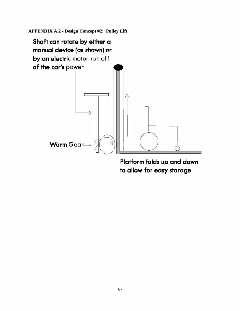
67
APPENDIX A.2 - Design Concept #2: Pulley Lift
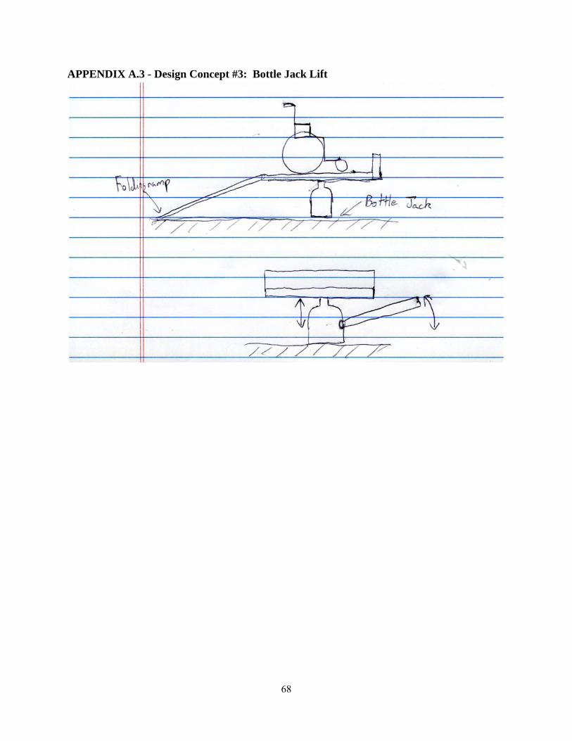
68
APPENDIX A.3 - Design Concept #3: Bottle Jack Lift
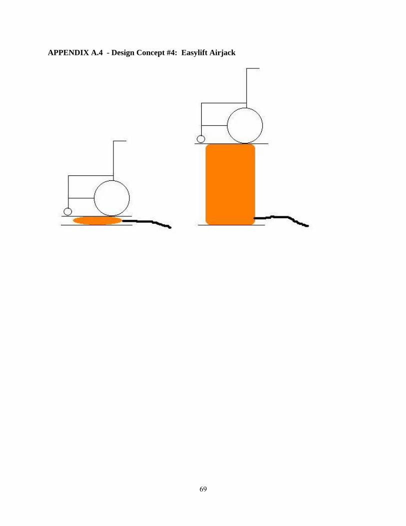
69
APPENDIX A.4 - Design Concept #4: Easylift Airjack
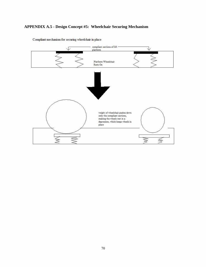
70
APPENDIX A.5 - Design Concept #5: Wheelchair Securing Mechanism
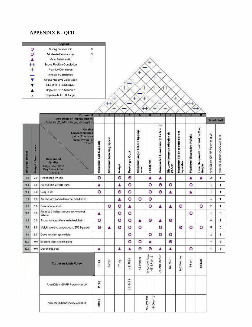
71
APPENDIX B - QFD
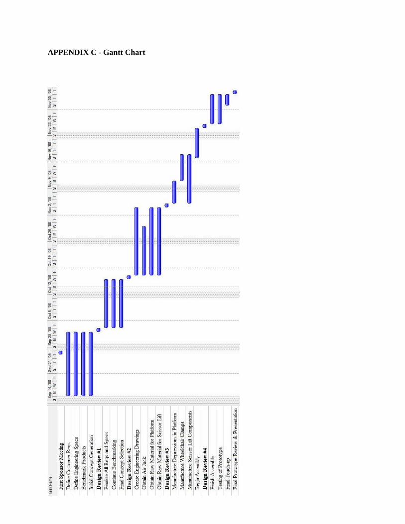
72
APPENDIX C - Gantt Chart

73
APPENDIX D - Biographies
Kevin Hsu was born and raised in southern New Hampshire. He has lived in the same house all his life in his hometown of Hollis, which is about an hour north of Boston. He decided to attend the University of Michigan because of his interest in engineering and Michigan’s renowned engineering programs. He also heard great things about the University from his brother, who also attended studying mechanical engineering. Kevin chose mechanical engineering because of its hands-on applications and its broad scope. He is interested in working somewhere full-time after graduation in the field of manufacturing, and eventually wants to obtain an MBA. He loves to play sports including basketball, tennis, volleyball, broomball, and frisbee. He also loves to ski, and skied in Colorado at Crested Butte for last year’s spring break.
Vania Kurikesu is from Livonia, MI, and has lived in the same house her entire life. When she first came to U of M she planned on majoring in electrical engineering, but changed her mind early in her college career. She switched to mechanical and absolutely loves how versatile the degree is. After having a really good experience at an internship two summers ago, she wants to work in the aviation industry after graduation and do project management. She prefers to stay away from a technical, design engineering position and instead do a mix of engineering and business. She also wants to go to grad school for an MBA at some point – just not sure if she wants to do it right away. In her free time she like playing volleyball, playing the piano and spending time with family and friends.
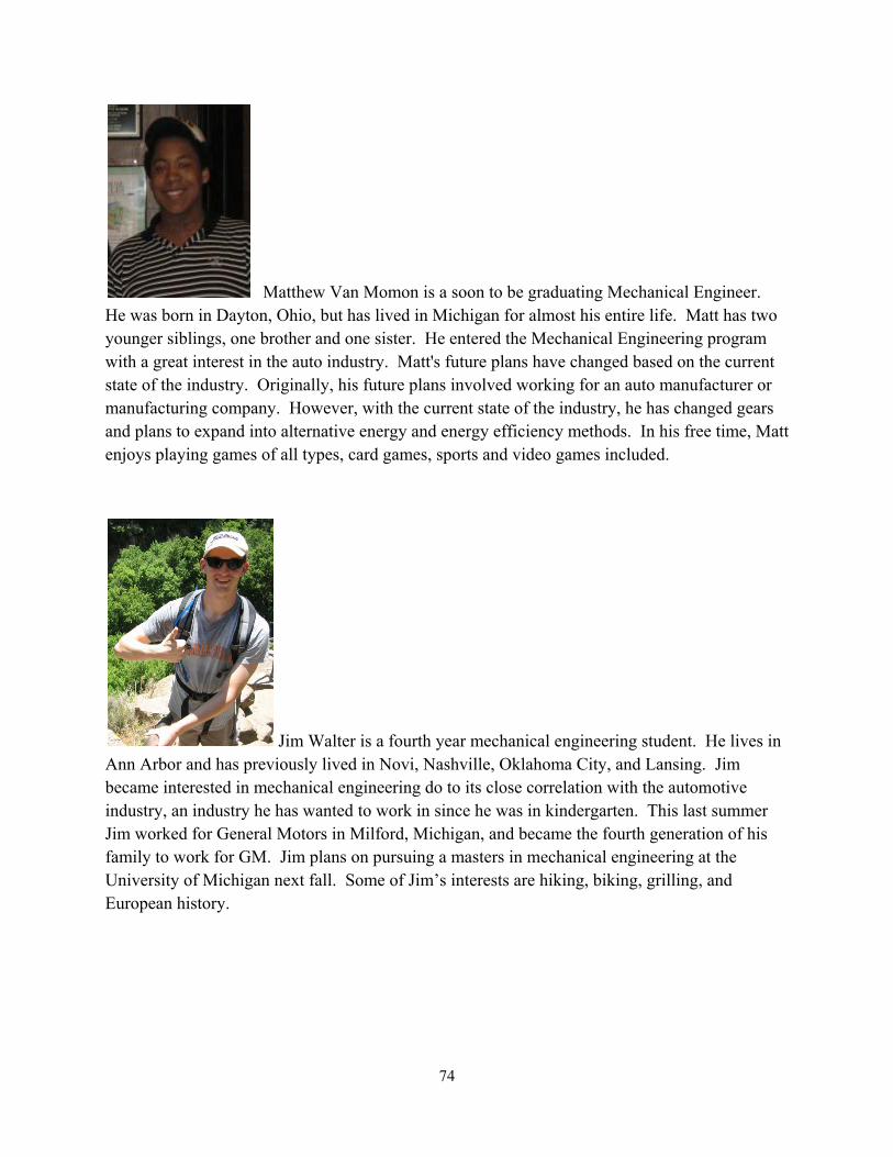
74
Matthew Van Momon is a soon to be graduating Mechanical Engineer. He was born in Dayton, Ohio, but has lived in Michigan for almost his entire life. Matt has two younger siblings, one brother and one sister. He entered the Mechanical Engineering program with a great interest in the auto industry. Matt's future plans have changed based on the current state of the industry. Originally, his future plans involved working for an auto manufacturer or manufacturing company. However, with the current state of the industry, he has changed gears and plans to expand into alternative energy and energy efficiency methods. In his free time, Matt enjoys playing games of all types, card games, sports and video games included.
Jim Walter is a fourth year mechanical engineering student. He lives in Ann Arbor and has previously lived in Novi, Nashville, Oklahoma City, and Lansing. Jim became interested in mechanical engineering do to its close correlation with the automotive industry, an industry he has wanted to work in since he was in kindergarten. This last summer Jim worked for General Motors in Milford, Michigan, and became the fourth generation of his family to work for GM. Jim plans on pursuing a masters in mechanical engineering at the University of Michigan next fall. Some of Jim’s interests are hiking, biking, grilling, and European history.
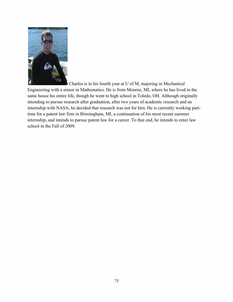
75
Charles is in his fourth year at U of M, majoring in Mechanical Engineering with a minor in Mathematics. He is from Monroe, MI, where he has lived in the same house his entire life, though he went to high school in Toledo, OH. Although originally intending to pursue research after graduation, after two years of academic research and an internship with NASA, he decided that research was not for him. He is currently working part-time for a patent law firm in Birmingham, MI, a continuation of his most recent summer internship, and intends to pursue patent law for a career. To that end, he intends to enter law school in the Fall of 2009.

76
APPENDIX E.1 - AmeriGlide 325-FP Hitch Wheelchair Lift [1]

77
APPENDIX E.2 - Braun Millennium Series Wheelchair Lift [2]

78
APPENDIX F.1 - Ramp Stresses and Forces Calculation:
ΣMA = Wcosθ(d) - Byh
By = Wcosθ(d/h)
Ay = Wcosθ – By = Ay = (1-d/L)Wcosθ
For 0 < ℓ < d
Ay
M(ℓ) = [W(1-d/L)cosθ] ℓ
Thus, max moment occurs at ℓ=d
M(d) = Wcosθ(1-d/L)d
to find max d, take derivative with respect to ℓ
ɗM/ɗℓ = -Wsinθ(1-2d/L)
d = L/2
Thus, the max bending moment is
Mmax = Wcosθ(L/4)
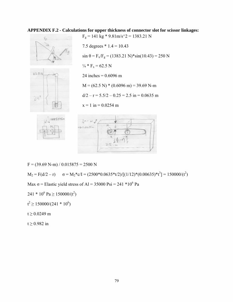
79
APPENDIX F.2 - Calculations for upper thickness of connector slot for scissor linkages: Fg = 141 kg * 9.81m/s^2 = 1383.21 N
7.5 degrees * 1.4 = 10.43
sin θ = Fx/Fg = (1383.21 N)*sin(10.43) = 250 N
¼ * Fx = 62.5 N
24 inches = 0.6096 m
M = (62.5 N) * (0.6096 m) = 39.69 N-m
d/2 – r = 5.5/2 – 0.25 = 2.5 in = 0.0635 m
x = 1 in = 0.0254 m
F = (39.69 N-m) / 0.015875 = 2500 N
M2 = F(d/2 – r) σ = M2*c/I = (2500*0.0635*t/2)/[(1/12)*(0.00635)*t3] = 150000/(t2)
Max σ = Elastic yield stress of Al = 35000 Psi = 241 *106 Pa
241 * 106 Pa ≥ 150000/(t2)
t2 ≥ 150000/(241 * 106)
t ≥ 0.0249 m
t ≥ 0.982 in
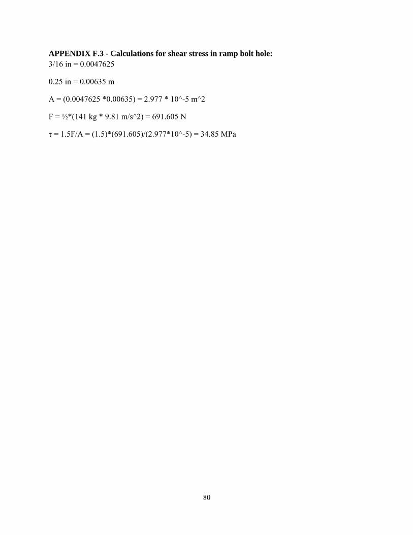
80
APPENDIX F.3 - Calculations for shear stress in ramp bolt hole: 3/16 in = 0.0047625
0.25 in = 0.00635 m
A = (0.0047625 *0.00635) = 2.977 * 10^-5 m^2
F = ½*(141 kg * 9.81 m/s^2) = 691.605 N
τ = 1.5F/A = (1.5)*(691.605)/(2.977*10^-5) = 34.85 MPa

81
APPENDIX G.1 - Prototype Parts
1. Base 2. Air Jack 3. Scissor Link Members 4. Pin Joints 5. Slot Joints 6. Tracks 7. Upper Supports 8. Ramps 9. Spacers 10. L-Bracket 11. Handle 12. Restraining Belts 13. Caster Assembly

82
APPENDIX G.2 – Prototype Dimensions (Dimensions in cm.)

83
APPENDIX H – Old Base (Dimensions in cm.)

84
APPENDIX I – Scissor Linkage (Dimensions in cm.)

85
APPENDIX J – Platform Track (Dimensions in cm.)
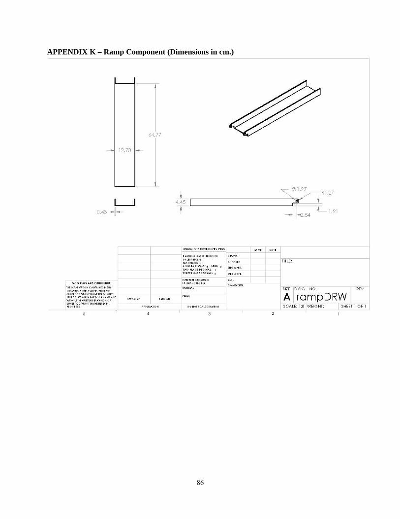
86
APPENDIX K – Ramp Component (Dimensions in cm.)
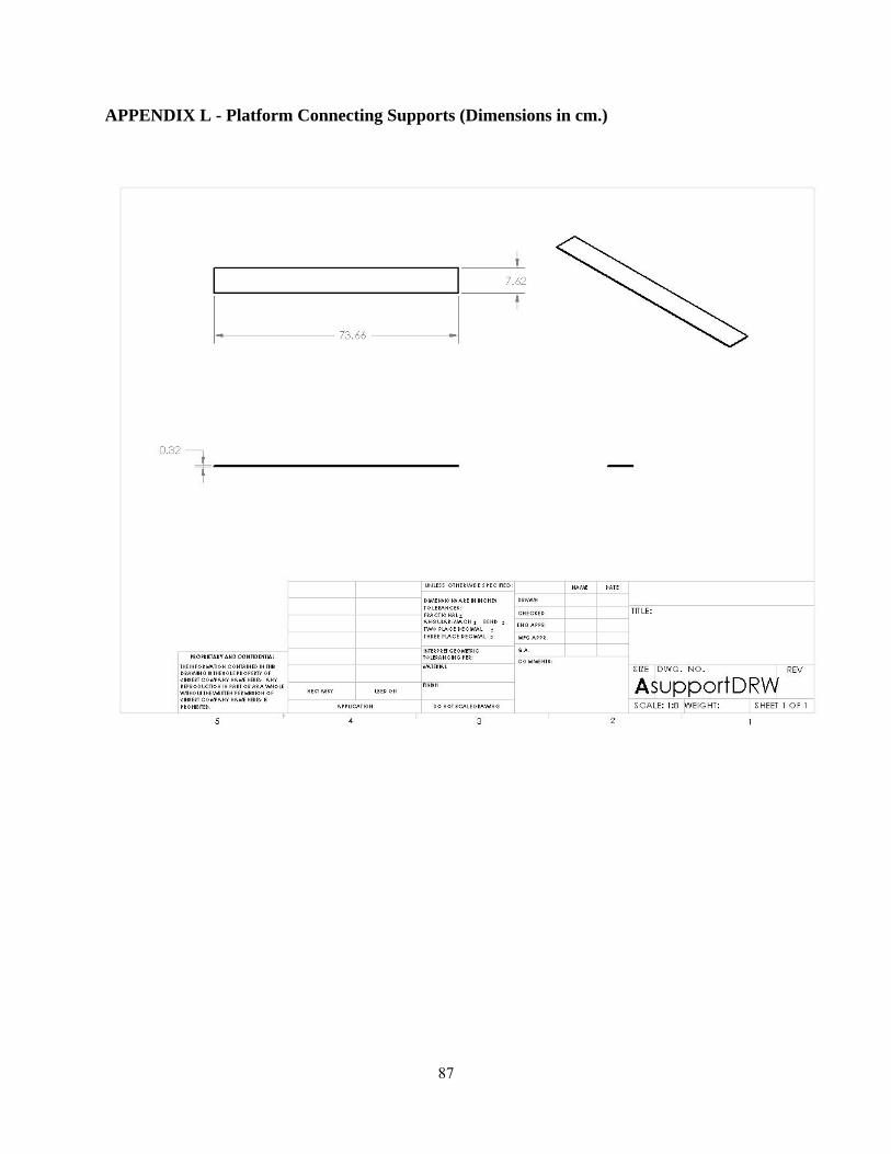
87
APPENDIX L - Platform Connecting Supports (Dimensions in cm.)
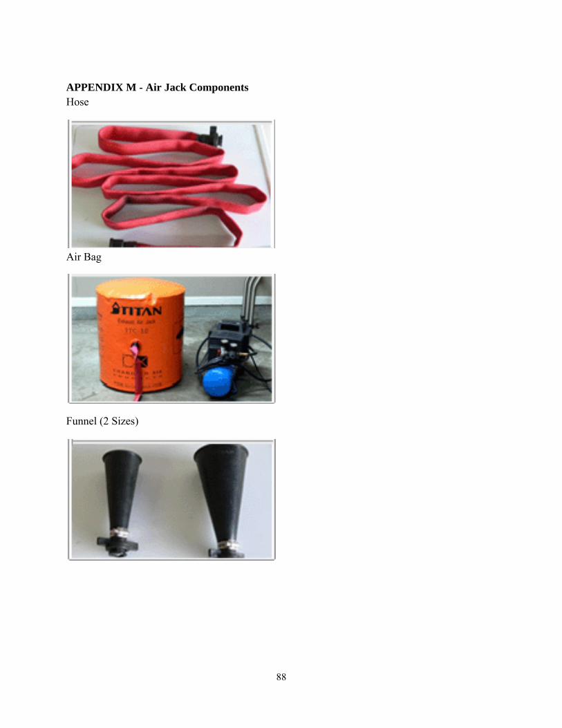
88
APPENDIX M - Air Jack Components Hose
Air Bag
Funnel (2 Sizes)
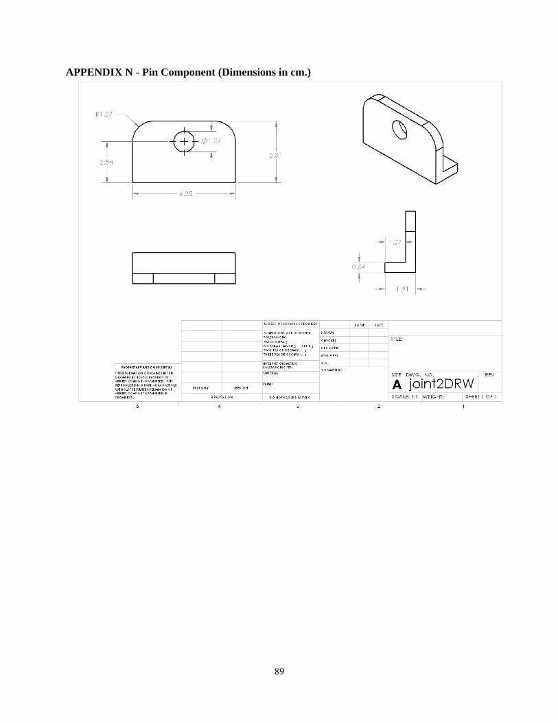
89
APPENDIX N - Pin Component (Dimensions in cm.)

90
APPENDIX O - Slot Component (Dimensions in cm.)
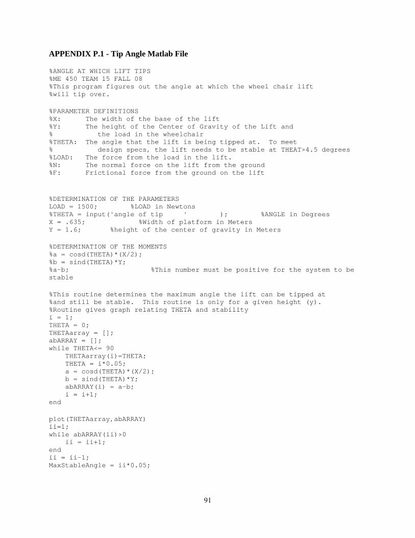
91
APPENDIX P.1 - Tip Angle Matlab File %ANGLE AT WHICH LIFT TIPS %ME 450 TEAM 15 FALL 08 %This program figures out the angle at which the wheel chair lift %will tip over. %PARAMETER DEFINITIONS %X: The width of the base of the lift %Y: The height of the Center of Gravity of the Lift and % the load in the wheelchair %THETA: The angle that the lift is being tipped at. To meet % design specs, the lift needs to be stable at THEAT>4.5 degrees %LOAD: The force from the load in the lift. %N: The normal force on the lift from the ground %F: Frictional force from the ground on the lift %DETERMINATION OF THE PARAMETERS LOAD = 1500; %LOAD in Newtons %THETA = input('angle of tip ' ); %ANGLE in Degrees X = .635; %Width of platform in Meters Y = 1.6; %height of the center of gravity in Meters %DETERMINATION OF THE MOMENTS %a = cosd(THETA)*(X/2); %b = sind(THETA)*Y; %a-b; %This number must be positive for the system to be stable %This routine determines the maximum angle the lift can be tipped at %and still be stable. This routine is only for a given height (y). %Routine gives graph relating THETA and stability i = 1; THETA = 0; THETAarray = []; abARRAY = []; while THETA<= 90 THETAarray(i)=THETA; THETA = i*0.05; a = cosd(THETA)*(X/2); b = sind(THETA)*Y; abARRAY(i) = a-b; i = i+1; end plot(THETAarray,abARRAY) ii=1; while abARRAY(ii)>0 ii = ii+1; end ii = ii-1; MaxStableAngle = ii*0.05;
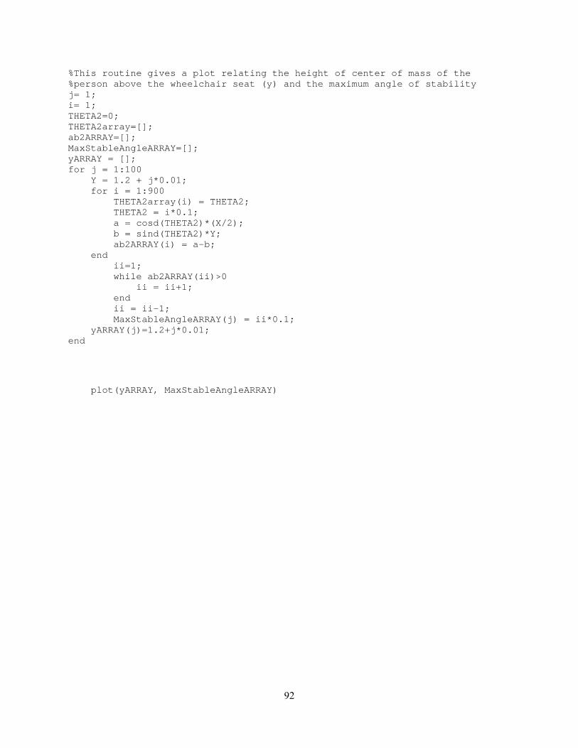
92
%This routine gives a plot relating the height of center of mass of the %person above the wheelchair seat (y) and the maximum angle of stability j= 1; i= 1; THETA2=0; THETA2array=[]; ab2ARRAY=[]; MaxStableAngleARRAY=[]; yARRAY = []; for j = 1:100 Y = 1.2 + j*0.01; for i = 1:900 THETA2array(i) = THETA2; THETA2 = i*0.1; a = cosd(THETA2)*(X/2); b = sind(THETA2)*Y; ab2ARRAY(i) = a-b; end ii=1; while ab2ARRAY(ii)>0 ii = ii+1; end ii = ii-1; MaxStableAngleARRAY(j) = ii*0.1; yARRAY(j)=1.2+j*0.01; end plot(yARRAY, MaxStableAngleARRAY)
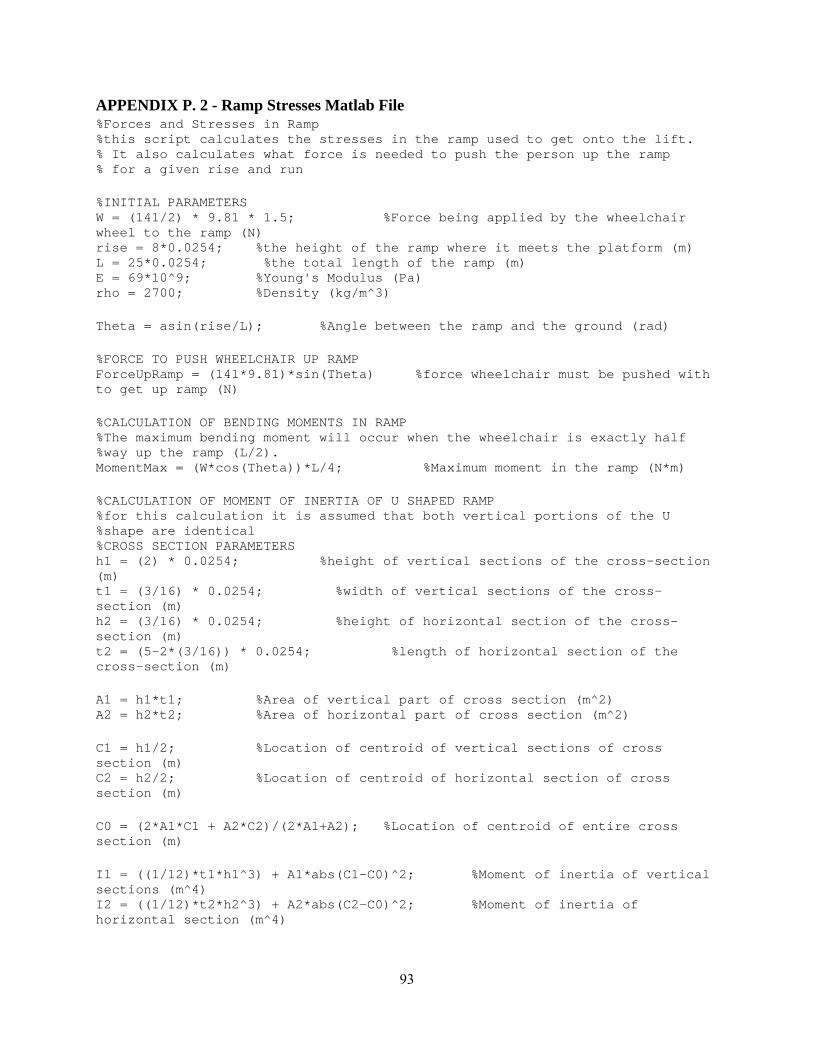
93
APPENDIX P. 2 - Ramp Stresses Matlab File %Forces and Stresses in Ramp %this script calculates the stresses in the ramp used to get onto the lift. % It also calculates what force is needed to push the person up the ramp % for a given rise and run %INITIAL PARAMETERS W = (141/2) * 9.81 * 1.5; %Force being applied by the wheelchair wheel to the ramp (N) rise = 8*0.0254; %the height of the ramp where it meets the platform (m) L = 25*0.0254; %the total length of the ramp (m) E = 69*10^9; %Young's Modulus (Pa) rho = 2700; %Density (kg/m^3) Theta = asin(rise/L); %Angle between the ramp and the ground (rad) %FORCE TO PUSH WHEELCHAIR UP RAMP ForceUpRamp = (141*9.81)*sin(Theta) %force wheelchair must be pushed with to get up ramp (N) %CALCULATION OF BENDING MOMENTS IN RAMP %The maximum bending moment will occur when the wheelchair is exactly half %way up the ramp (L/2). MomentMax = (W*cos(Theta))*L/4; %Maximum moment in the ramp (N*m) %CALCULATION OF MOMENT OF INERTIA OF U SHAPED RAMP %for this calculation it is assumed that both vertical portions of the U %shape are identical %CROSS SECTION PARAMETERS h1 = (2) * 0.0254; %height of vertical sections of the cross-section (m) t1 = (3/16) * 0.0254; %width of vertical sections of the cross-section (m) h2 = (3/16) * 0.0254; %height of horizontal section of the cross-section (m) t2 = (5-2*(3/16)) * 0.0254; %length of horizontal section of the cross-section (m) A1 = h1*t1; %Area of vertical part of cross section (m^2) A2 = h2*t2; %Area of horizontal part of cross section (m^2) C1 = h1/2; %Location of centroid of vertical sections of cross section (m) C2 = h2/2; %Location of centroid of horizontal section of cross section (m) C0 = (2*A1*C1 + A2*C2)/(2*A1+A2); %Location of centroid of entire cross section (m) I1 = ((1/12)*t1*h1^3) + A1*abs(C1-C0)^2; %Moment of inertia of vertical sections (m^4) I2 = ((1/12)*t2*h2^3) + A2*abs(C2-C0)^2; %Moment of inertia of horizontal section (m^4)
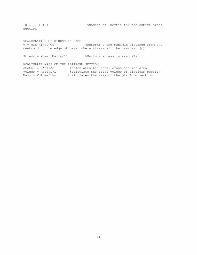
94
I0 = I1 + I2; %Moment of inertia for the entire cross section %CALCULATION OF STRESS IN RAMP y = max(h1-C0,C0); %Determine the maximum distance from the centroid to the edge of beam, where stress will be greatest (m) Stress = MomentMax*y/I0 %Maximum stress in ramp (Pa) %CALCULATE MASS OF THE PLATFORM SECTION Atotal = 2*A1+A2; %calculates the total cross section area Volume = Atotal*L; %calculate the total volume of platform section Mass = Volume*rho %calculates the mass of the platform section
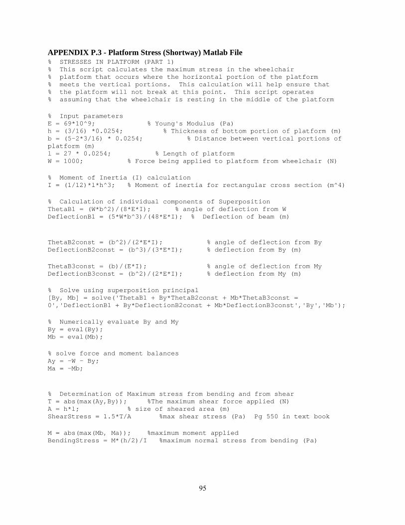
95
APPENDIX P.3 - Platform Stress (Shortway) Matlab File % STRESSES IN PLATFORM (PART 1) % This script calculates the maximum stress in the wheelchair % platform that occurs where the horizontal portion of the platform % meets the vertical portions. This calculation will help ensure that % the platform will not break at this point. This script operates % assuming that the wheelchair is resting in the middle of the platform % Input parameters E = 69*10^9; % Young's Modulus (Pa) h = (3/16) *0.0254; % Thickness of bottom portion of platform (m) b = (5-2*3/16) * 0.0254; % Distance between vertical portions of platform (m) l = 27 * 0.0254; % Length of platform W = 1000; % Force being applied to platform from wheelchair (N) % Moment of Inertia (I) calculation I = (1/12)*l*h^3; % Moment of inertia for rectangular cross section (m^4) % Calculation of individual components of Superposition ThetaB1 = (W*b^2)/(8*E*I); % angle of deflection from W DeflectionB1 = (5*W*b^3)/(48*E*I); % Deflection of beam (m) ThetaB2const = (b^2)/(2*E*I); % angle of deflection from By DeflectionB2const = (b^3)/(3*E*I); % deflection from By (m) ThetaB3const = (b)/(E*I); % angle of deflection from My DeflectionB3const = (b^2)/(2*E*I); % deflection from My (m) % Solve using superposition principal [By, Mb] = solve('ThetaB1 + By*ThetaB2const + Mb*ThetaB3const = 0','DeflectionB1 + By*DeflectionB2const + Mb*DeflectionB3const','By','Mb'); % Numerically evaluate By and My By = eval(By); Mb = eval(Mb); % solve force and moment balances Ay = -W - By; Ma = -Mb; % Determination of Maximum stress from bending and from shear T = abs(max(Ay,By)); %The maximum shear force applied (N) A = h*l; % size of sheared area (m) ShearStress = 1.5*T/A %max shear stress (Pa) Pg 550 in text book M = abs(max(Mb, Ma)); %maximum moment applied BendingStress = M*(h/2)/I %maximum normal stress from bending (Pa)

96
APPENDIX P.4 - Platform Stress (Longway) Matlab File %BENDING OF PLATFORM LENGTHWISE %this script calculates the bending stress on the lift platform %along the length of the platform that results from the weight of the %wheelchair. It operates under the assumption that the force from the back %wheels of the wheelchair are much greater than the front. %PARAMETER DEFINITIONS a = 5 * 0.0254; %Distance from edge of platform to the first support, which is where the platform will attach to the underlying structure (m) wb = 20 * 0.0254; %Distance between front and back wheels of the wheelchair, which is 20.5 inches (m) L = 27 * 0.0254; %Total length of the platformt that the wheelchair rests on (m) W1 = (1383/2)*1.5; %Force of back wheel of chair acting on the platform (N) rho = 2700; %Density of the material used for platform (kg/m^3) %CALCULATION OF MAXIMUM MOMENTS Mmax1 = W1*a; %Maximum moment if the wheelchair wheel is to the left of support A Mmax2 = W1*((L-wb)-a); %Maximum moment if the wheelchair wheel is to the right of support A. The maximum distance this can be is (L-wb) %anything more would mean the front wheels of the %chair would fall of the platform Mmax = max(Mmax1, Mmax2); %Determines which of the two potential maximum moments is larger %CALCULATE THE MOMENT OF INERTIA OF THE U SHAPED CROSS SECTION %for this calculation it is assumed that both vertical portions of the U %shape are identical %CROSS SECTION PARAMETERS h1 = 2 * 0.0254; %height of vertical sections of the cross-section (m) t1 = (3/16) * 0.0254; %width of vertical sections of the cross-section (m) h2 = (3/16) * 0.0254; %height of horizontal section of the cross-section (m) t2 = (5-2*(3/16)) * 0.0254; %length of horizontal section of the cross-section (m) A1 = h1*t1; %Area of vertical part of cross section (m^2) A2 = h2*t2; %Area of horizontal part of cross section (m^2) C1 = h1/2; %Location of centroid of vertical sections of cross section (m) C2 = h2/2; %Location of centroid of horizontal section of cross section (m) C0 = (2*A1*C1 + A2*C2)/(2*A1+A2); %Location of centroid of entire cross section (m) I1 = ((1/12)*t1*h1^3) + A1*abs(C1-C0)^2; %Moment of inertia of vertical sections (m^4)
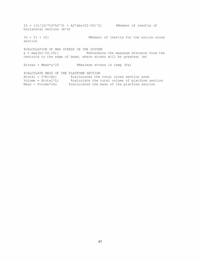
97
I2 = ((1/12)*t2*h2^3) + A2*abs(C2-C0)^2; %Moment of inertia of horizontal section (m^4) I0 = I1 + I2; %Moment of inertia for the entire cross section %CALCULATION OF MAX STRESS IN THE SYSTEM y = max(h1-C0,C0); %Determine the maximum distance from the centroid to the edge of beam, where stress will be greatest (m) Stress = Mmax*y/I0 %Maximum stress in ramp (Pa) %CALCULATE MASS OF THE PLATFORM SECTION Atotal = 2*A1+A2; %calculates the total cross section area Volume = Atotal*L; %calculate the total volume of platform section Mass = Volume*rho %calculates the mass of the platform section

98
APPENDIX P.5 - Scissor Linkage Lateral Stress %STRESSES IN SCISSOR LINKAGES FROM LATERAL FORCES %this script finds the maximum stress that occurs in the %scissor linkages from a lateral force applied to the lift %PARAMETER DEFINITIONS F = 250; %Lateral force applied (N) L = 20 * 0.0254; %Length of scissor linkage from tip to tip(m) t = (3/4)*0.0254; %Thickness of scissor linkage [parallel to direction of the pins] (m) w = 1* 0.0254; %Width of scissor linkage [perpenicular to direction of the pins] (m) y1 = 1 * 0.0254; %Distance from edge of linkage to the center of pin holes on the ends (m) y2 = 9 * 0.0254; %Distance from center of on pin hole to center of next pin hole (m) d = 0.5 * 0.0254; %Diameter of pin holes (m) rho = 2700; %Density (kg/m^3) %MOMENT CALCULATION Moment = F*(L-2*y1); %This is the maximum moment around a pin hole. The pin holes are the locations where the maximum stress will occur %STRESS CONCENTRATION FACTOR %There is no stress concentration factor because the analysis is for a %Ductile material failing by yield (Mechanical Behavior of Materials by %Norman Dowling, pg 277) %MOMENT OF INERTIA CALCULATION %this calculates the moment of inertia for the cross section around the pin %holes. I = ((1/12)*(w-d)*t^3); %Moment of inertia for the cross section(m^4) %STRESS CALCULATION %calculates the maximum stress at the location of the pin holes Stress = Moment*(t/2)/I %Max stress in cross section (Pa) %MASS CALCULATION %calculates the combined masses of all 8 seperate linkages combined Mass = 8*rho*(w*L*t)
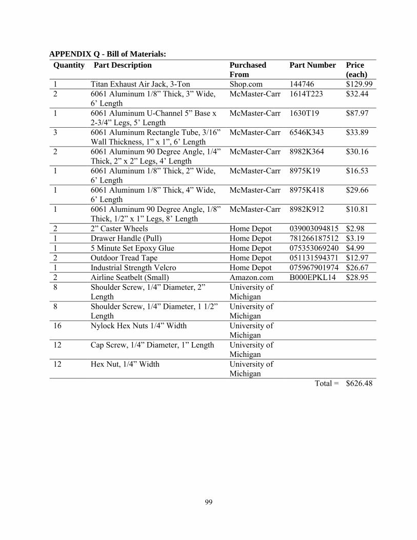
99
APPENDIX Q - Bill of Materials: Quantity Part Description Purchased
From Part Number Price
(each) 1 Titan Exhaust Air Jack, 3-Ton Shop.com 144746 $129.992 6061 Aluminum 1/8” Thick, 3” Wide,
6’ Length McMaster-Carr 1614T223 $32.44
1 6061 Aluminum U-Channel 5” Base x 2-3/4” Legs, 5’ Length
McMaster-Carr 1630T19 $87.97
3 6061 Aluminum Rectangle Tube, 3/16” Wall Thickness, 1” x 1”, 6’ Length
McMaster-Carr 6546K343 $33.89
2 6061 Aluminum 90 Degree Angle, 1/4” Thick, 2” x 2” Legs, 4’ Length
McMaster-Carr 8982K364 $30.16
1 6061 Aluminum 1/8” Thick, 2” Wide, 6’ Length
McMaster-Carr 8975K19 $16.53
1 6061 Aluminum 1/8” Thick, 4” Wide, 6’ Length
McMaster-Carr 8975K418 $29.66
1 6061 Aluminum 90 Degree Angle, 1/8” Thick, 1/2” x 1” Legs, 8’ Length
McMaster-Carr 8982K912 $10.81
2 2” Caster Wheels Home Depot 039003094815 $2.98 1 Drawer Handle (Pull) Home Depot 781266187512 $3.19 1 5 Minute Set Epoxy Glue Home Depot 075353069240 $4.99 2 Outdoor Tread Tape Home Depot 051131594371 $12.97 1 Industrial Strength Velcro Home Depot 075967901974 $26.67 2 Airline Seatbelt (Small) Amazon.com B000EPKL14 $28.95 8 Shoulder Screw, 1/4” Diameter, 2”
Length University of Michigan
8 Shoulder Screw, 1/4” Diameter, 1 1/2” Length
University of Michigan
16 Nylock Hex Nuts 1/4” Width University of Michigan
12 Cap Screw, 1/4” Diameter, 1” Length University of Michigan
12 Hex Nut, 1/4” Width University of Michigan
Total = $626.48

100
APPENDIX R.1 - SimaPro Design for Environment – Mass Breakdown
0
500000
1000000
1500000
2000000
2500000
3000000
3500000
4000000
4500000
Raw Air Water Waste
Mass(grams)
Emissions Breakdown
6060 AlMgSi0.5 (grams) Titanium (grams)

101
APPENDIX R.2 - SimaPro Design for Environment – Characterization
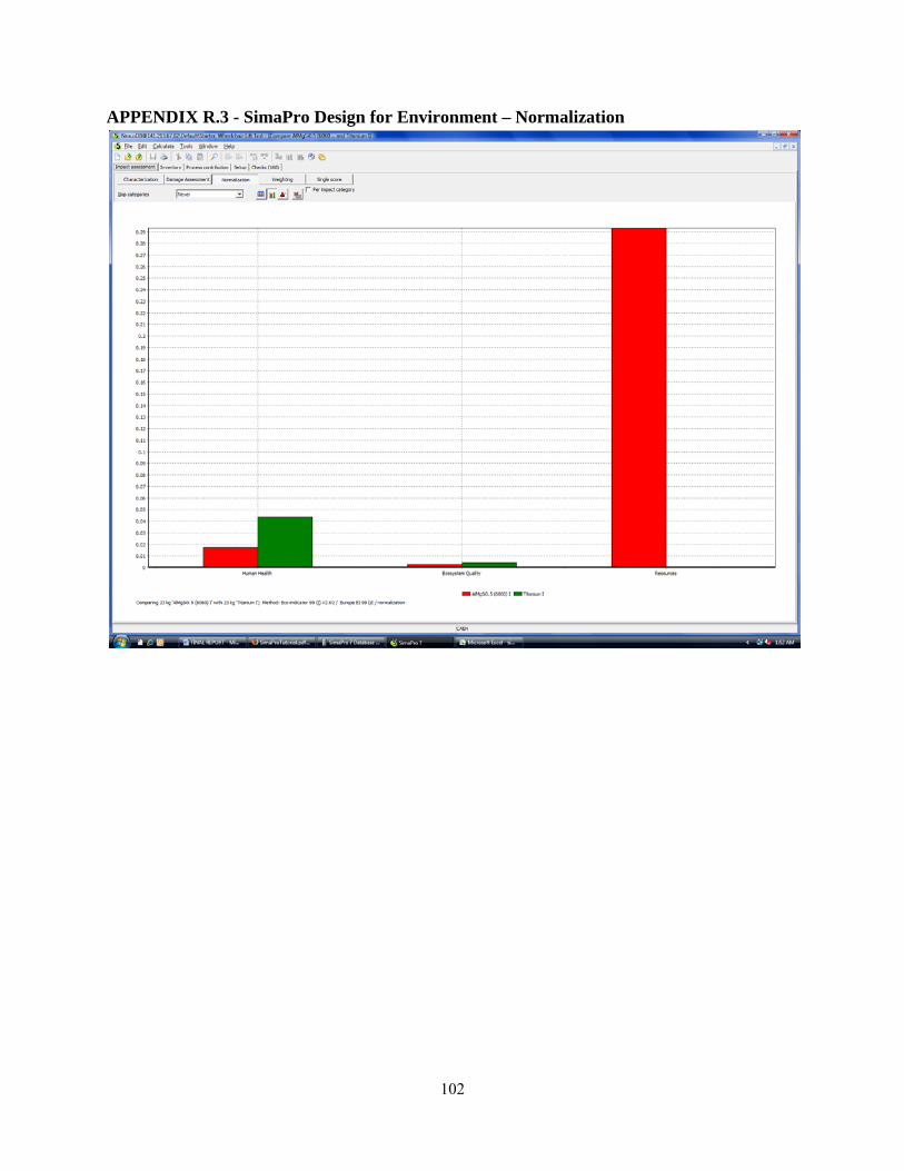
102
APPENDIX R.3 - SimaPro Design for Environment – Normalization

103
APPENDIX R.4 - SimaPro Design for Environment – Single Score

104
APPENDIX S.1 - Failure Mode Engineering Analysis
Part Number
and Function
Potential Failure Mode
Potential Effects of
Failure
Severity (S)
Potential Causes of Mechanism
Failure
Occurance
(O)
Detection (D
) RPN
Base Unstable Lift could tip over 10
Person leaning in chair 6 5 300
Deformation
Lift no longer operable, could tip 10
Person leaning in chair 5 2 100
Material Yield
Lift no longer operable, could tip 10
Person leaning in chair 5 2 100
Base Sliders Binding
lift wouldn't raise smoothly 5
Inproper lubrication 7 5 175
Material Yield Lift no longer operable 8 overloading 2 2 32
Shearing
Lift would veer to one side 9 overloading 1 2 18
Base Pivots Binding
lift wouldn't raise smoothly 5
Inproper lubrication 8 5 200
Material Yield Lift no longer operable 8 overloading 2 2 32
Loose fitting
Lift would veer to one side 7 overloading 5 2 70
Scissor Linkage Loosening
Lift would become unstable 6
Repeated thermal expansion 4 4 96
Buckling Lift would collapse 9 overloading 2 1 18
Material Yield linkages would be misalligned 5 overloading 2 2 20
Pins (shoulder bolts) Shearing
Lift no longer operable 8 overloading 2 2 32
Loosening
Lift would become unstable 5
cyclical stressing 4 4 80
Castors Seizure Difficult to move lift 3
Inproper lubrication 6 2 36
Material Yield Difficult to move lift 3 overloading 2 2 12
Handles Material Yield Lift would be dropped 6 overloading 2 2 24
Part Number
and Function
Potential Failure Mode
Potential Effects of
Failure
Severity (S)
Potential Causes of Mechanism
Failure
Occurance
(O)
Detection
(D)
RPN

105
Platform Sliders Shearing
Lift no longer operable 9 overloading 1 2 18
Binding
Lift would veer to one side 7
Inproper lubrication 7 5 245
Material Yield lift wouldn't raise smoothly 5 overloading 2 2 20
Ramps Deformation Ramps unusable 7 overloading 2 2 28
Material Yield Ramps unusable 7 overloading 2 2 28
Ramp Pivot (bolt) Schear
Wheelchair would fall 9 overloading 4 2 72
Air Jack Puncture Rapid deflation 9 setting lift on glass shards 4 6 216
Polution Release carbon monixide 5
user doesn't properly deflate bag 9 5 225
Air Jack Valve Loose Fitting
Unwanted deflation 7
improper manufacturing 2 4 56
Material Yield unable to hold air 7
improper manufacturing 2 4 56
Air Jack Hose Kinking
unable to inflate 4
poor design of hose 9 1 36