engineering spec ic-250-3c - bigge cooled, 4-cylinder, 199 cid (3.3l), 3.74” (9.5 cm) bore,...
TRANSCRIPT

EngineeringSpec IC-250-3C
Copyright 2009 Broderson Manufacturing Corp. Form #ID109CSpecifi cations Subject to Change
Page 1 of 11 Date: Mar. 2009
Replaces: Form ID108CDated: Oct. 2008
Manufacturing Corp.(913) 888-0606 FAX (913) 888-8431www.bmccranes.com
The IC-250-3C is a self-propelled Industrial Crane designed for material handling and maintenance and repair of equipment, with special features of self-loading cargo decks, 4-wheel steer, and front-wheel drive (4-wheel drive optional). The basic unit consists of a chassis and hydraulic boom assembly. The chassis includes a frame, four hydraulic independently controlled outriggers, engine, torque converter, powershift 4-speed transmission, front planetary drive/steer axle and rear steer-only axle, fuel tank, hydraulic tank, control station, power steering and dual power brakes. The boom assembly includes a hydraulic powered continuous rotation turret, proportional 4-section telescopic boom, hydraulic boom elevating cylinder, hydraulic boom telescope cylinder and hydraulic powered hoist. Rated Capacity Limiter is standard.
IC-250-3C:4-section hydraulically extended boom with capacity of 36,000 pounds (16,330 kg) at a 6-foot (1.83 m) load radius. Horizontal reach of 50 feet 1 inch (15.26 m) and vertical reach of 60 feet 7 inches (18.47 m).
General:Length:
Overall 23 feet 6 inches (7.16 m)Chassis 15 feet 6 inches (4.72 m)
Width: 7 feet 10 inches (2.39 m)
Height:Overall 7 feet 11 inches (2.41 m)Deck 47 inches (1.19 m)
Wheelbase: 100 inches (2.54 m))
Ground Clearance: 13 inches (33 cm)
Angle of Approach: 25 degrees
Angle of Departure: 23 degrees
Outriggers:Spread 14 feet 9 inches (4.50 m)Penetration 3 inches (7.62 cm)
Boom Movement:Rotation ContinuousElevation 0 to 75 degreesTelescope 34 feet 6 inches (10.52 m)
Boom Speeds:Rotation 2.0 RPMElevation 24 secondsTelescope 53 seconds
Extension: W/O Boom Extension With Boom ExtensionSheave Height (Nominal): 60 feet 7 inches (18.46 m) 79 feet 6 inches (24.23 m)Horizontal Reach: 50 feet 1 inch (15.26 m) 70 feet 1 inch (21.36 m)
Weight:Total 37,700 pounds (17,100 kg)Front Axle 17,400 pounds (7,900 kg)Rear Axle 20,300 pounds (9,200 kg)

Copyright 2009 Broderson Manufacturing Corp. Form #ID109CSpecifi cations Subject to Change
Page 2 of 11Date: Mar. 2009Manufacturing Corp.
General: (cont’d.)Turning Radius: (4-Wheel Steering) 14 feet 4 inches (4.37 m)
Aisle Width for 90° Turn: 11 feet 11 inches (3.61 m)
Steering Modes: Rear Steer, Round Steer, Crab Steer
Road Speed: 18 MPH (29 kph)
Drawbar Pull: Cummins 3.3L 18,600 pounds* (8,437 kg) GM 5.7L 21,400 pounds* (9,706 kg)
Gradeability: 64 percent* *Calculated, wheels spin below these values in 2-wheel drive.
Grade Limit: 15 percent
Engine:Standard:
Cummins QSB3.3L Turbo, EPA Tier 3:Cummins Model QSB3.3 turbocharged diesel engine. Water cooled, 4-cylinder, 199 CID (3.3L), 3.74” (9.5 cm)bore, 4.53” (11.53 cm) stroke, 99 HP (74 kw) at governed speed of 2,500 RPM. Maximum torque is 304 ft. lbs. (410-n-m) at 1,400 RPM. 120-amp alternator included. 30 gallon (114 L) fuel tank capacity. High temperature and low oil pressure shutdown included in engine management system. Throttle control switch for setting engine speed at 1,200 or 1,800 RPM. Charge air cooler and grid heater included.
Optional Engine and Engine Accessories:GM 5.7L V-8 EPA Tier 2 Woodward LPG Fuel:
GM Model 5.7L V-8 industrial LPG engine complete with electronic LPG fuel injection, and engine management system. Includes water cooled, 8-cylinder, 350 CID (5.7L), 4.00” (10.16 cm) bore, 3.48” (8.84 cm) stroke, 135 HP (100 kw) at governed speed of 2,500 RPM. Maximum torque is 307 ft. lbs. (416-n-m) at 1,500 RPM. Also includes special exhaust valves, seats and valve rotators for use with LPG, 100-amp alternator, catalytic converter, dual 43 pound LPG tanks with quick disconnects, and high temperature and low oil pressure shutdown. US EPA Tier 2 emissions certifi ed. Net Weight: 175 pounds (80 kg), including 2 aluminum LP tanks.
Spark Arrester Muffl er:Spark arrester muffl er used in addition to standard muffl er. Net Weight: 10 pounds (4.5 kg)
Catalytic Converter: Catalytic converter for diesel engines. Reduces engine emissions. Net Weight: 10 pounds (4.5 kg)
Engine Heater:Heater for engine. Engine coolant heater installed with hoses in coolant system to circulate warm water through engine. Plugs into 120-volt AC extension cord: 1,500 watts.
Transmission:Standard 2-Wheel Drive:
Powershift transmission with four speeds in forward and reverse. Provides powershifts at any engine speed in any gear. All shifting is done with a single lever electrical control mounted on the steering column. Multiple-disc clutch packs operated by solenoid valves provide reverse, neutral, forward and speed selection. Equipped with oil cooler and fi lter.

Copyright 2009 Broderson Manufacturing Corp. Form #ID109CSpecifi cations Subject to Change
Page 3 of 11Date: Mar. 2009Manufacturing Corp.
Optional 4-Wheel Drive Transmission:Same as 2WD transmission with an additional output shaft to drive the rear axle. Rear output shaft runs faster than front by a ratio of 1.58 to 1. Rear axle has more reduction than front axle to match speed of front. Electrohydraulic control for shifting between 2WD and 4WD. This option includes the 4-wheel drive axle listed below. (Net Weight: 310 pounds for 4WD system)
Transmission gear ratios: Forward and Reverse (2WD & 4WD) 1st 5.72 to 1.0 2nd 3.23 to 1.0 3rd 1.77 to 1.0 4th 1.00 to 1.0
Torque Converter:Standard:
Stall torque ratio of 2.2:1, attached to engine fl ywheel.
Front Axle:Standard:
Planetary drive/steer front axle with 15.78 to 1.0 ratio. Differential equipped with “limited slip” feature. Driving effort is applied to wheel that has traction. Front axle mounted rigidly to frame.
Calculated Performance: Gear Travel Speeds (MPH) Gradeability* Drawbar Pull (pounds) 1st 3 (5 km/h) 64 18,600 (8,440 kg) 2nd 5 (8 km/h) 36 10,700 (4,850 kg) 3rd 10 (16 km/h) 19 5,800 (2,630 kg) 4th 18 (29 km/h) 10 3,100 (1,410 kg) *Calculated, wheels may spin in 1st or 2nd gear before these values are reached with 2-wheel drive.
Rear Axle:Standard
2-Wheel Drive:Steering axle with 1½° oscillation in either direction.
Optional 4-Wheel Drive:Planetary drive/steer axle with 24.98 to 1.0 ratio. Differential is not “limited slip” in rear axle. 1½° oscillation in either direction. (Axle ratio compatible with 4WD transmission rear output ratio to match front axle speed. Net Weight: 230 pounds (104 kg)
Steering:Standard:
Hydraulic steering unit with two 3-inch cylinders attached to each axle. Allows limited steering when engine is not running. A switch on the control panel is used to select rear-wheel steering or four-wheel (round) steering.
Brakes:Standard:
Split-system, four-wheel hydraulically-boosted multiple-plate wet disc brakes. Uses mineral oil. Hand lever actuated disc-type parking brake on transmission.
Tires:Standard:
2-Wheel & 4-Wheel Drive 385/65D22.5, 16-ply, high-traction on/off road tread.
Tire Options:Non-Marking Pnuematic:
385/65D22.5 16-ply. Net Weight: 140 pounds (64 kg)
Foam Filling of Tires:Foam fi lling of four IC-250 tires. Net Weight: 2,000 pounds (900 kg)

Copyright 2009 Broderson Manufacturing Corp. Form #ID109CSpecifi cations Subject to Change
Page 4 of 11Date: Mar. 2009Manufacturing Corp.
Tire Options: (Cont’d)Spare Tire and Wheel, Mounted:
Extra wheel with 385/65D22.5 tire mounted: Ready for service. Net Weight: 335 pounds (152 kg)
Spare Tire and Wheel, Mounted, Non-Marking Pnuematic:Extra wheel with Non-Marking 385/65D22.5 tire mounted, ready for service. Net Weight: 335 pounds (152 kg)
Chassis:Standard:
Cargo Deck:Total Deck Area: 80 Square Feet (7.43m 2)(Front deck 94” (239 cm) X 62” (157 cm), RH side deck 182” (462 cm) X 28” (71 cm)). A maximum of 17,000 pounds (7,700 kg) may be carried on the deck when centered over or between axles. Seven stake pockets are provided along edges of deck for 1-inch (2.5 cm) pipe stakes. Stakes furnished. Cargo decks have skid resistant coating.
Chassis: (Cont’d)Headlight and Taillight Grilles:
Steel protective grilles for headlights and taillights. Easily removable for replacing bulbs.
Outriggers:Four hydraulic out-and-down outriggers of box-beam construction. Independent controls for each outrigger. Hydraulic cylinders are equipped with direct-connected holding valves. Pad dimensions: 9 inches (22.86 cm) x 9 inches (22.86 cm).
Pulling Eyes:Two heavy eyes in front bumper provide for attachment of hook block so main winch line can be used for pulling loads at or near fl oor level. Also for anchoring tag lines from load on hook.
Tie Downs:Two holes in the rear bumper (in conjunction with the pulling eyes) provide tie down locations for transporting crane by truck or cargo container.
Accessory Storage Box:Consists of front deck plate with removable and lockable cover, and box for carrying sheave block and other items. Storage box is 14” (36 cm) deep x 12½” (32 cm) long x 36½” (93 cm) wide.
Lifting Rings:Consists of four rings, one at each corner of the load deck, so sling can be attached for lifting crane. Rings hang below deck surface when not in use
Chassis Options and Accessories:Auxiliary Winch:
Optional worm gear winch, mounted behind front bumper, with a single lever control at the operator’s console. Hydraulic powered to provide bare drum line pull of 10,000 lbs. (4,500 kg) at 40 ft. (12 m) per minute. Winch drum is 3½” (9 cm) dia. by 10” (25 cm) long. This winch includes 115 ft. (35 m) of 7/16” (11 mm) wire rope, hook and four-way roller guide. Rated load on the wire rope is 5,800 pounds (2,600 kg). Net Weight: 250 pounds (113 kg)
Pintle Hook - Rear:T-60-AOL Holland pintle hook mounted on rear frame member, provides capacity for 6,000 pound (2,700 kg) tongue weight and 30,000 (13,600 kg) pound trailer weight. Net Weight: 15 pounds (7 kg)
Pintle Hook - Front:T-60-AOL Holland pintle hook mounted on front frame member, provides capacity for 6,000 pound (2,700 kg) tongue weight and 30,000 (13,600 kg) pound trailer weight. Net Weight: 45 pounds (20 kg)
Outrigger Shoes:Steel outrigger shoes, 18 X 18 inch (46 cm X 46 cm) octagonal shape with storage posts on rear bumper. Net Weight: 170 pounds (77 kg)

Copyright 2009 Broderson Manufacturing Corp. Form #ID109CSpecifi cations Subject to Change
Page 5 of 11Date: Mar. 2009Manufacturing Corp.
Chassis Options and Accessories: (Cont’d)Rearview Mirrors:
One right-hand and one left-hand mirror, 6” (15 cm) wide x 16” (41 cm) high, mounted on deck stakes. Pivot out of way when contacted by obstacle at side of deck. Net Weight: 12 pounds (5.4 kg)
Operator Compartment:Standard:
Operator control station provides one-position access to all chassis and crane functions. Includes adjustable operator’s seat and seat belt.
Operator Guard: (Not Available with Cab)Tubular steel weldment with heavy expanded steel mesh top section, bolts over the operator’s compartment. Net Weight: 60 pounds (27 kg)
Operator Guard Cover:Clear vinyl cover goes over guard for inclement weather. Has zipper and velcro roll-up door. Net Weight: 15 pounds (27 kg)
All Weather Cab:Consists of rigid mounted canopy section and removable hinged door with safety glass. Rugged canopy structure with laminated glass front and top. Door is equipped with a keyed lock to protect operator’s station. Includes defroster fan, dome light, 12,400 BTU heater with 2-speed fan and 12V electric windshield wiper. There are sliding windows in the door and right-hand side. Net Weight: 220 pounds (100 kg)
Cab Heater only:Provides 12,400 BTU heater with two-speed fan for units without All Weather Cab. Net Weight: 12 pounds (5.4 kg)
Windshield Washer:Provides reservoir, pump and nozzle for windshield washer.
Floor Mat:Vinyl mat with foam backing covers fl oor, front wall and lower portion of right hand wall of operator’s compartment. (Net Weight: 5 pounds)
Operator’s Suspension Seat:Provides additional operator comfort. Net Weight: 15 pounds (7 kg)
Noise Reduction Kit - Cab:Includes vinyl fl oor mats and control valve cover and side panels of foam-backed, perforated vinyl for noise reduction. Net Weight: 15 pounds (7 kg)
Air Conditioning:Provides factory system using R134A refrigerant. Compact AC unit mounted in operator’s area, fan cooled condenser mounted under fuel tank and belt driven compressor with magnetic clutch driven by engine. Net Weight 125 lbs. (57 kg)
Electrical System:Standard:
12 Volt DCBattery:
Diesel Units: Group 31 with 950 CCA rating.Gas Units: Group 27 with 540 CCA rating.
Lighting Group:Consists of two 12V-lamps, with high and low beams for driving; tail, brake and turn signal lights and backup lights in rear; front turn signals and emergency fl asher switch at operator’s station. 12V horn actuated by button located on shifting control.
Copyright 2009 Broderson Manufacturing Corp. Form #ID109CSpecifi cations Subject to Change
Page 6 of 11Date: Mar. 2009Manufacturing Corp.
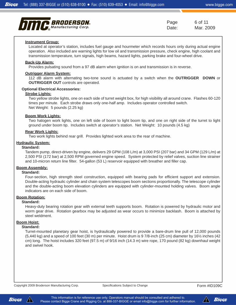
Instrument Group:Located at operator’s station, includes fuel gauge and hourmeter which records hours only during actual engine operation. Also included are warning lights for low oil and transmission pressure, check engine, high coolant and transmission temperature, turn signals, high beams, hazard lights, parking brake and four-wheel drive.
Back-Up Alarm:Provides pulsating sound from a 97 dB alarm when ignition is on and transmission is in reverse.
Outrigger Alarm System:112 dB alarm with alternating two-tone sound is actuated by a switch when the OUTRIGGER DOWN or OUTRIGGER OUT controls are operated.
Optional Electrical Accessories:Strobe Lights:
Two yellow strobe lights, one on each side of turret weight box, for high visibility all around crane. Flashes 60-120 times per minute. Each strobe draws only one-half amp. Includes operator controlled switch. Net Weight: 5 pounds (2.25 kg)
Boom Work Lights:Two halogen work lights, one on left side of boom to light boom tip, and one on right side of the turret to light ground under boom tip. Includes switch at operator’s station. Net Weight: 10 pounds (4.5 kg)
Rear Work Lights:Two work lights behind rear grill. Provides lighted work area to the rear of machine.
Hydraulic System:Standard:
Tandem pump, direct-driven by engine, delivers 29 GPM (108 L/m) at 3,000 PSI (207 bar) and 34 GPM (129 L/m) at 2,500 PSI (172 bar) at 2,500 RPM governed engine speed. System protected by relief valves, suction line strainer and 10-micron return line fi lter. 54-gallon (53 L) reservoir equipped with breather and fi ller cap.
Boom Assembly:Standard:
Four-section, high strength steel construction, equipped with bearing pads for effi cient support and extension. Double-acting hydraulic cylinder and chain system telescopes boom sections proportionally. The telescope cylinder and the double-acting boom elevation cylinders are equipped with cylinder-mounted holding valves. Boom angle indicators are on each side of boom.
Boom Rotation:Standard:
Heavy-duty bearing rotation gear with external teeth supports boom. Rotation is powered by hydraulic motor and worm gear drive. Rotation gearbox may be adjusted as wear occurs to minimize backlash. Boom is attached by steel weldment.
Boom Hoist:Standard:
Turret-mounted planetary gear hoist, is hydraulically powered to provide a bare-drum line pull of 12,000 pounds (5,440 kg) and a speed of 100 feet (30 m) per minute. Hoist drum is 9 7/8-inch (25 cm) diameter by 16½ inches (42 cm) long. The hoist includes 320 feet (97.5 m) of 9/16 inch (14.3 m) wire rope, 170 pound (82 kg) downhaul weight and swivel hook.
Copyright 2009 Broderson Manufacturing Corp. Form #ID109CSpecifi cations Subject to Change
Page 7 of 11Date: Mar. 2009Manufacturing Corp.
Should you require an option or special equipment not listed please consult your dealer salesperson or BMC®.
Tel (913) 888-0606Fax (913) 888-8431www.bmccranes.com
Dimensions and values shown are for reference purposes only. Specifi cations subject to change.
Manufacturing Corp.14741 West 106th StreetLenexa, KS 66215 USA
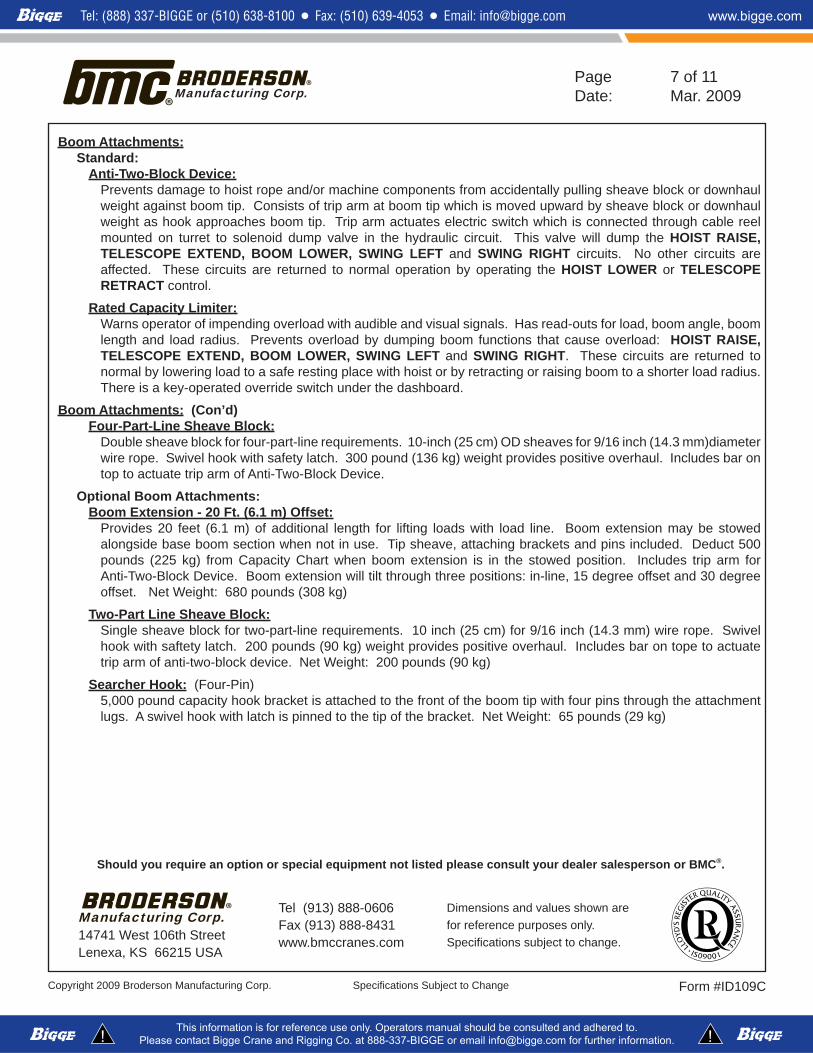
Boom Attachments:Standard:
Anti-Two-Block Device:Prevents damage to hoist rope and/or machine components from accidentally pulling sheave block or downhaul weight against boom tip. Consists of trip arm at boom tip which is moved upward by sheave block or downhaul weight as hook approaches boom tip. Trip arm actuates electric switch which is connected through cable reel mounted on turret to solenoid dump valve in the hydraulic circuit. This valve will dump the HOIST RAISE, TELESCOPE EXTEND, BOOM LOWER, SWING LEFT and SWING RIGHT circuits. No other circuits are affected. These circuits are returned to normal operation by operating the HOIST LOWER or TELESCOPE RETRACT control.
Rated Capacity Limiter:Warns operator of impending overload with audible and visual signals. Has read-outs for load, boom angle, boom length and load radius. Prevents overload by dumping boom functions that cause overload: HOIST RAISE, TELESCOPE EXTEND, BOOM LOWER, SWING LEFT and SWING RIGHT. These circuits are returned to normal by lowering load to a safe resting place with hoist or by retracting or raising boom to a shorter load radius. There is a key-operated override switch under the dashboard.
Boom Attachments: (Con’d)Four-Part-Line Sheave Block:
Double sheave block for four-part-line requirements. 10-inch (25 cm) OD sheaves for 9/16 inch (14.3 mm)diameter wire rope. Swivel hook with safety latch. 300 pound (136 kg) weight provides positive overhaul. Includes bar on top to actuate trip arm of Anti-Two-Block Device.
Optional Boom Attachments: Boom Extension - 20 Ft. (6.1 m) Offset:
Provides 20 feet (6.1 m) of additional length for lifting loads with load line. Boom extension may be stowed alongside base boom section when not in use. Tip sheave, attaching brackets and pins included. Deduct 500 pounds (225 kg) from Capacity Chart when boom extension is in the stowed position. Includes trip arm for Anti-Two-Block Device. Boom extension will tilt through three positions: in-line, 15 degree offset and 30 degree offset. Net Weight: 680 pounds (308 kg)
Two-Part Line Sheave Block:Single sheave block for two-part-line requirements. 10 inch (25 cm) for 9/16 inch (14.3 mm) wire rope. Swivel hook with saftety latch. 200 pounds (90 kg) weight provides positive overhaul. Includes bar on tope to actuate trip arm of anti-two-block device. Net Weight: 200 pounds (90 kg)
Searcher Hook: (Four-Pin) 5,000 pound capacity hook bracket is attached to the front of the boom tip with four pins through the attachment lugs. A swivel hook with latch is pinned to the tip of the bracket. Net Weight: 65 pounds (29 kg)

Copyright 2009 Broderson Manufacturing Corp. Form #ID109CSpecifi cations Subject to Change
Page 8 of 11Date: Mar. 2009Manufacturing Corp.
IC-250-3CChart
LOAD
30
45
6075
ROTATION
150
30
45
7560
27'-1"
3"
1'-3"
75°
60'-4"
9"
9"
7'-10"
14'-8"7'-4"
14'
7'-11"
6'-0 1/8"
3'-11"24.5°
2'-11"4'-3" 3'-4"
15'-5"8'-4"
3'-9" 4'-0"2'-9"
25.7°
4'-6"15'-7 RETRACTED
7'-10"
LCLC
50'-1 EXTENDED
38 56505950175017501300
BOLD LINE ARE LIMITED BY TIPPING. OTHER CAPACITIES ARE LIMITED BY CAPACITIES ON RUBBER ARE 75% OF TIPPING LOADS. CAPACITIES BELOW
CAPACITIES ON OUTRIGGERS OUT & DOWN ARE 85% OF TIPPING LOADS. BOOM EXTENSION MAY ONLY CARRY LOADS WITH OUTRIGGERS DOWN.BOOM EXTENSION LOADS MUST NOT EXCEED MAIN BOOM CAPACITY.
20 FOOT BOOM EXTENSION STRUCTURAL CAPACITIES- STRAIGHT OR OFFSETEXT.
CAUTION
0°
30°15°
ANGLEOFFSET
2600---
---
0°27502500---
15°
58
6670
BOOM
62
54504642
---
---
------
---350600900
27003300510060°
365042505000
---------------
MAIN BOOM ANGLE
300026002300
30°340027002400
40° 50°410029002500
---
---
------
900---
11001400
---
---------
700---
10001300
620043003200
70°7000
34004800
75°
340035503100
23502700
2100
40004700
MAIN BOOM CAPACITIES ARE IN POUNDS AND APPLY TO OPERATION ON FIRM LEVEL SURFACE
3234
2830
222426
1820
20001750
23502700
4150
31003600
48005600
8
121416
10
FEET6
RADIUSLOAD
13000
64507550900010800
360° ROTATIONON RUBBER
16400
7150
20800
1670018700
121001350014900
985010900
750082008950
250003040036000
OVER FRONTO/R'S IN & DOWN
MAIN BOOM OR BOOM EXTENSION
26502300
30503500
5400
40004650
61006850
26502300
30503600
5900
42005000
69008150
360° ROTATIONO/R'S IN & DOWN
15000
780090001045012350
OVER FRONTON RUBBER
1850025050
9700120001550020300
30000
7000
121001350014900
109009850
750082008950
208001870016700
250003040036000
360° ROTATIONO/R'S OUT & DOWN
STRUCTURAL OR HYDRAULIC CAPABILITY.
LOADS TO 9000LOAD LINE FORUSE SINGLE PART
LBS. 180 LBS. LBS. 200 LBS.LOADS TO 18000
USE TWO PARTLOAD LINE FOR53 1/2"
LBS. 300 LBS.
LOAD LINE FORLOADS TO 36000
USE FOUR PART
55" 60"
BOOM EXTENSION DEDUCT: 500 LBS. WHEN STOWED ON BASE
15°
7' 5 3/8"
12'
20'16'
24'
66'30'RADIUS IN FEET FROM ROTATION TO LOAD
10'6' 18'14' 22'26' 46'38'34' 42' 50'54' 62'58' 70'
72'
48'
36'32'
28'
44'
40'
60'
56'52'
68'64'
79' 6"76'
30°
50°
40°
75° 70°
60°
0°
HE
IGH
T I
N F
EE
T A
BO
VE
GR
OU
ND
LCLC

Copyright 2009 Broderson Manufacturing Corp. Form #ID109CSpecifi cations Subject to Change
Page 9 of 11Date: Mar. 2009Manufacturing Corp.
IC-250-3CTurn Chart
16' 5" CLEARANCE CIRCLE(32' 10" DIAMETER)
6' 7"CORNER
CLEARANCE
14' 4" TURNINGRADIUS
11' 10" AISLE WIDTH
11' 10" AISLE WIDTH

Copyright 2009 Broderson Manufacturing Corp. Form #ID109CSpecifi cations Subject to Change
Page 10 of 11Date: Mar. 2009Manufacturing Corp.
IC-250-3CMetric Chart
150
30
45
7560
8.25 M
38 CM
75°
18.40 M
LOAD
30
45
6075
ROTATION
2.42 M1.83 M
1.19 M24.5°
89 CM1.31 M 1.02 M
4.71 M2.54 M
1.14 M 1.23 M84 CM
25.7°
1.37 M4.76 M RETRACTED
2.38 M
LCLC
15.27 M EXTENDED
23 CM
23 CM
2.39 M
4.49 M
2.23 M
4.27 M
7.5 CM
ARE LIMITED BY TIPPING. OTHER CAPACITIES ARE LIMITED BY STRUCTURALON RUBBER ARE 75% OF TIPPING LOADS. CAPACITIES BELOW BOLD LINE
CAPACITIES ON OUTRIGGERS ARE 85% OF TIPPING LOADS. CAPACITIES BOOM EXTENSION MAY ONLY CARRY LOADS WITH OUTRIGGERS DOWN.BOOM EXTENSION LOADS MUST NOT EXCEED MAIN BOOM CAPACITY.
6.1M BOOM EXTENSION STRUCTURAL CAPACITIES- STRAIGHT OR OFFSETEXT.
CAUTION
0°
30°15°
ANGLEOFFSET
1180---
---
0°12501130---
15°
14.0
15.216.0
BOOM
15.0
13.012.011.010.0
---
520680860
12201490231060°
254029603330
---
MAIN BOOM ANGLE
136011801040
30°154012201090
40° 50°186013101130
---
7309001130
---
7109001130
281019501450
70°3170
15402180
75°
240020801820
15401590
1610
28503300
MAIN BOOM CAPACITIES ARE IN KILOGRAMS AND APPLY TO OPERATION ON FIRM LEVEL SURFACE
8.09.0
7.06.0
4.55.0
13801100
1760223028403210
2.0
3.03.54.0
2.5
METERS1.8
RADIUSLOAD
6900
3690428049705790
360° ROTATIONON RUBBER
7440
3800
11530
88909770
74008130
6220
44105210
135401560016330
OVER FRONTO/R'S IN & DOWN
MAIN BOOM OR BOOM EXTENSION
17801430
2280282034403860
18701440
2470321042404980
360° ROTATIONO/R'S IN & DOWN
7880
4350493056806680
OVER FRONTON RUBBER
840012960
60507590937011140
13600
3800
74008130
6220
44105210
1153097708890
135401560016330
360° ROTATIONO/R'S OUT & DOWN
OR HYDRAULIC CAPABILITY.
380 2210610 570270 1930500 500190 1700420 360160 1650410 320
17.0 --- ------ --- 152018.0 --- ------ --- 136020.0 --- ------ --- 108021.3 --- ------ --- 950
USE SINGLE PARTLOAD LINE FORLOADS TO 4080KG.WT 82 KG.
1.36 M LOAD LINE FOR
WT 136KG.LOADS TO 16330 KG.
USE FOUR PART
1.52 M1.4 M
USE TWO PART
LOADS TO 8165 KG.LOAD LINE FOR
WT 91 KG.
BOOM EXTENSION DEDUCT: 225 kg WHEN STOWED ON BOOM
HE
IGH
T I
N M
ET
ER
S A
BO
VE
GR
OU
ND
15°
32.27
23
RADIUS IN METERS FROM ROTATION TO LOAD131211108 964 5 7 17181514 16
24.2
60°
50°
30°
40°
70°75°
456789
1011121314151617181920212223
192021.3LC
LC
Copyright 2009 Broderson Manufacturing Corp. Form #ID109CSpecifi cations Subject to Change
Page 11 of 11Date: Mar. 2009Manufacturing Corp.
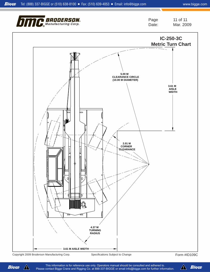
IC-250-3CMetric Turn Chart
5.00 M CLEARANCE CIRCLE(10.00 M DIAMETER)
2.01 MCORNER
CLEARANCE
4.37 M TURNINGRADIUS
3.61 M AISLE WIDTH
3.61 M AISLE WIDTH